8 Channel Smart Preamp with AD/DA
User Manual V2
Welcome to your new EVO SP8 Smart Preamp. EVO SP8 has been designed to
remove the technical barriers creatives face when exploring the often intimidating
world of audio and make recording simple for everyone.
EVO SP8 includes 8 High-Performance EVO Preamps with innovative Smartgain
technology, 2 JFET Instrument Inputs and Pristine Converters.
We hope you enjoy using EVO SP8 and it helps you in your creative endeavors,
whatever they may be!
Work smarter not harder.
WELCOME
WELCOME

EVO makes recording easy
WELCOME

CONTENTS
03
Registration with ARC
01 Declaration of Conformities
02 Installation/Setup
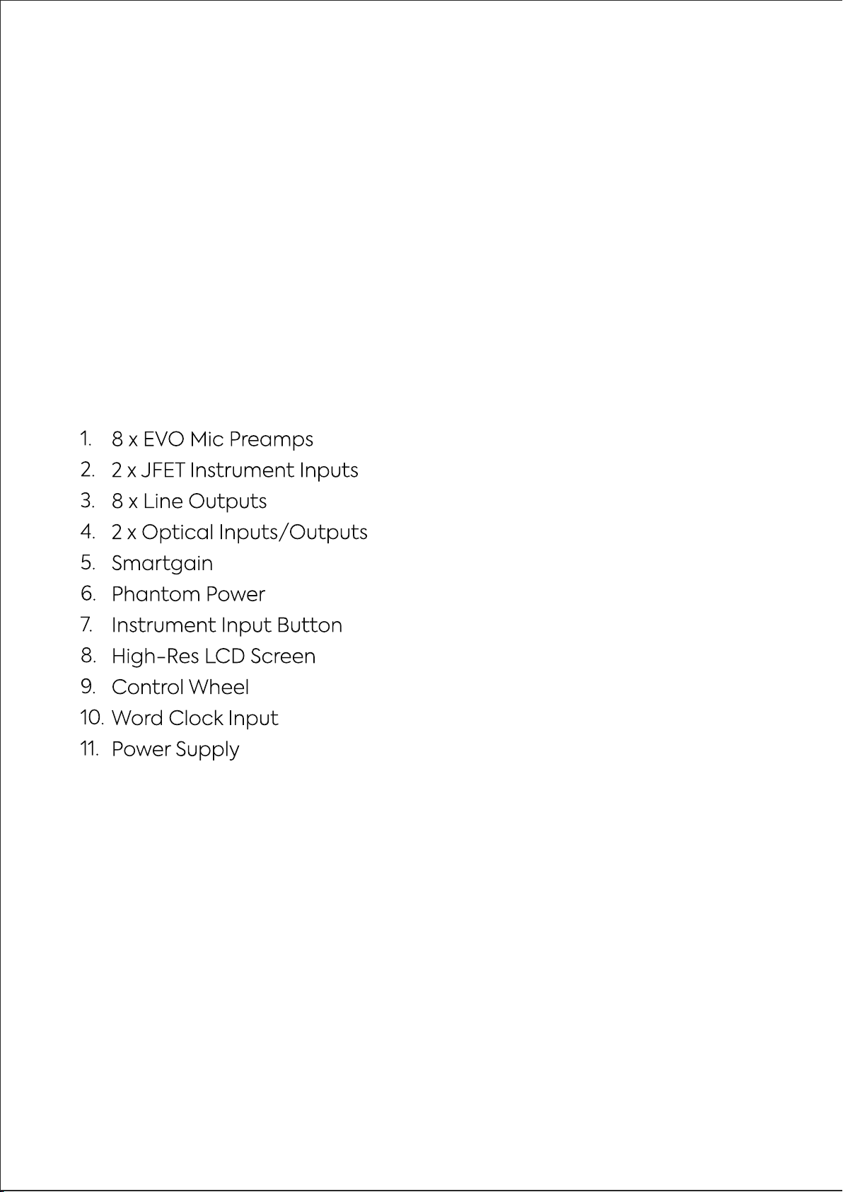
04 Hardware Features
05 EVO Expanded System
06 EVO SP8 Rack Mounting
Mic Preamps & Line Level Inputs
Features
Smartgain Mode
Smartgain on the Extended EVO System
Digital Inputs & Outputs
Word Clock Input
Metering
Power
Clocking
Factory Reset
Line Outputs


DECLARATION OF CONFORMITIES
Re-orient or relocate the receiving
antenna
01
Increase the separation between the
equipment and receiver
02
03
Connect the equipment into an
outlet on a dierent circuit from that
to which the receiver is connected
04
Consult the dealer or an experienced
radio/TV technician for help
DECLARATION
This apparatus has been tested and found to comply with the limits of
a class-A digital device, pursuant to Part 15B of the FCC Rules. These
limits are designed to provide reasonable protection against harmful
interference in a residential installation.
This equipment generates, uses and can radiate radio frequency
energy and if not installed and used in accordance with the
instructions, may cause harmful interference to radio communications.
If this equipment does cause harmful interference to radio or television
reception, which can be determined by turning the equipment o and
on, the user is encouraged to try to correct the interference by one or
more of the following measures:
We, EVO Audient, Aspect House, Herriard, Hampshire, RG25 2PN, UK,
01256 381944, declare under our sole responsibility that the product EVO SP8
complies with Part 15 of FCC Rules.
Operation is subject to the following two conditions:
1. This device may not cause harmful interference,
2. This device must accept any interference received,
including interference that may cause undesired operation
Audient Ltd has conformed where applicable, to the European Union’s Directive
EN 63000:2018 on Restrictions of Hazardous Substances (RoHS) as well as the following
sections of California law which refer to RoHS, namely sections 25214.10, 25214.10.2, and 58012,
Health and Safety Code; Section 42475.2, Public Resources
We, EVO Audient, declare that the product, the EVO SP8, to which this declaration
relates, is in material conformity with the appropriate CE standards and
directives for an audio product designed for consumer use.
We, EVO Audient, declare that the product, the EVO SP8, to which this declaration
relates, is in material conformity with the appropriate UKCA standards and
directives for an audio product designed for consumer use.
Under an environment with electrostatic discharge, the device may cease to output sound
(EUT could not operate properly). This requires the user reset the device by unplugging &
re-connecting to host computer.
As a device that provides power to other equipment power management features are
inappropriate for this product.
IEC 62368 Test Report with Japan deviation.
We, EVO Audient, declare that the product, the EVO SP8, to which this declaration relates,
is in material conformity with the appropriate PSE standards and directives for an audio
product designed for consumer use. METI Ordinance Appendix 12 J55032(H29).
DECLARATION

INSTALLATION / SETUP
Plug the EVO SP8 into a mains outlet using the mains power lead included in
the box. For more information on how to connect your device to your host
interface, please read the ‘Clocking Conguration’
section of this Manual.
The rst time powering on EVO SP8, you will be asked to follow the setup
procedure, allowing you to customise EVO SP8’s settings to your liking.
Firstly, you can adjust and set the brightness of all of EVO SP8’s hardware
LEDs, including the LED Ring, to suit your studio environment. Use the Control
Wheel to adjust the slider and then click the Control Wheel to save your
settings and then hit ‘Next’
INSTALLATION / SETUP
Initial Setup

Now you can select your initial Clock Source, Sample Rate and Analogue
Output source depending on your current setup.
You can change these settings at any time from the setup menu if you
wish to.
INSTALLATION / SETUP

REGISTRATION WITH AUDIENT ARC
EVO SP8 comes bundled with a collection of professional software and
services, giving you everything you need to start recording.
Go to arc.audient.com and select “register your product” and enter
your details to create an account.
You will then receive a verication email to your inbox, double check
your Spam and Junk folders if you cannot see this. Once you’ve veried
your account, register your EVO SP8 by entering the serial number and
the unique 4-digit PIN found on the underside of the EVO SP8.
Once you have registered the product, you can select from a wide
array of free software and plugins, giving you easy access to powerful
creative tools straight away.
REGISTRATION

REGISTRATION
HARDWARE
HARDWARE FEATURES
HARDWARE
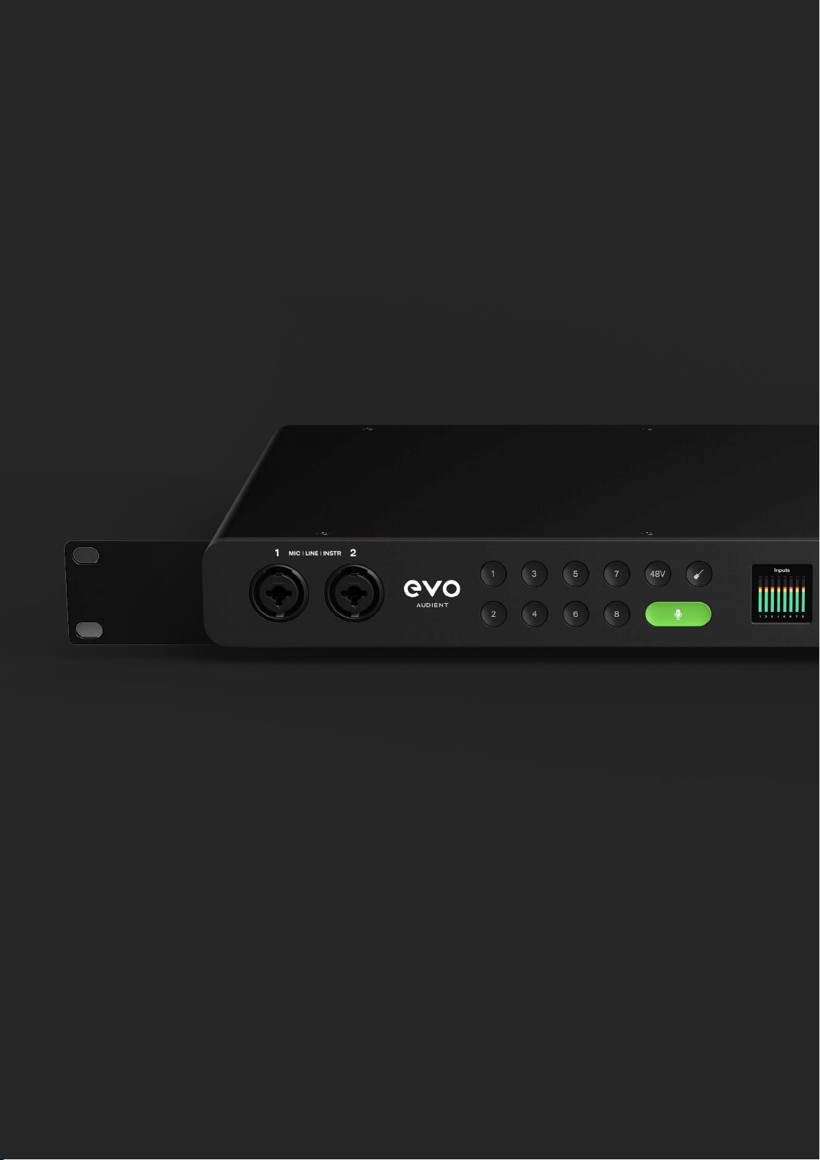
EVO SP8 includes eight high-quality EVO Mic Preamps, accessible through
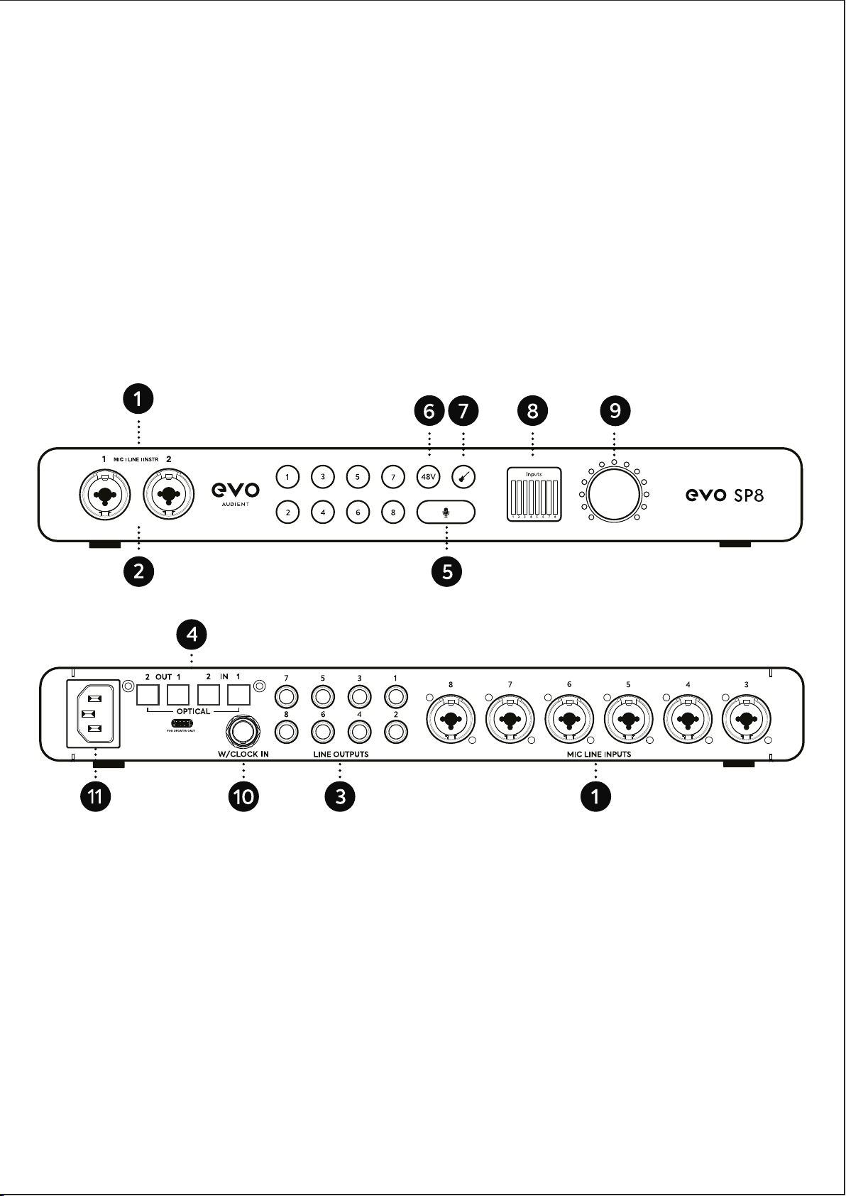
the Combi-jacks found on the front and rear of the unit.
Mic Preamps and Line Level Inputs
To connect a line-level device, use a ¼” TRS jack, which will connect
to the centre of the Combi-connector. The Line Input automatically
reduces your signal level slightly to minimise the chance of overloading
the input and causing distortion.
To connect a microphone, use an XLR cable which has three pins.
HARDWARE
TRS Jack
Connection
XLR Cable
Connection

HARDWARE
EVO SP8 can lower the signal level by 8 decibels and boost it by up to 50
decibels allowing you to get the perfect recording level, this is known as the
Gain.
You can manually control the gain by pressing one of the Input Buttons,
numbered 1-8, and then adjusting the Control Wheel. The screen will then
show the current gain level in decibels.
When pressing any Input Button on EVO SP8’s front panel, the input screen
will show the Input Status Screen.
When pressing an Input Button, the status screen will display: the input
number, the gain setting in dB, and an independent channel meter for
referencing your levels.
When an input is selected, the hardware will now control that channel, so
you can use the Control Wheel to adjust the input gain with decibel level
accuracy, as well as toggling channel mute, phantom power for condenser
mics, or instrument mode for guitars and basses on channel 1+2.
HARDWARE
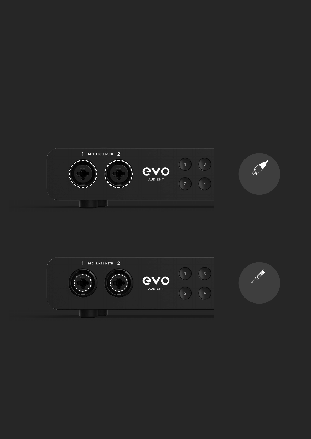
To quickly mute a channel, hold down the channels input button until
the Mute screen is shown, and the channel button begins ashing. When
a channel is muted, the gain level is replaced with the Mute icon, this will
remain in place until mute is deactivated, by again holding down the
channel button.
To activate phantom power, select the channel, then press the 48V Button,
which will then illuminate red and activate a temporary feature toggle
screen. This is set independently per channel so if you navigate away to a
dierent channel, where phantom power isn’t activated, the 48V Button will
no longer be illuminated. To turn o 48V, press the 48V Button again, which
will again display the feature toggle screen.
HARDWARE
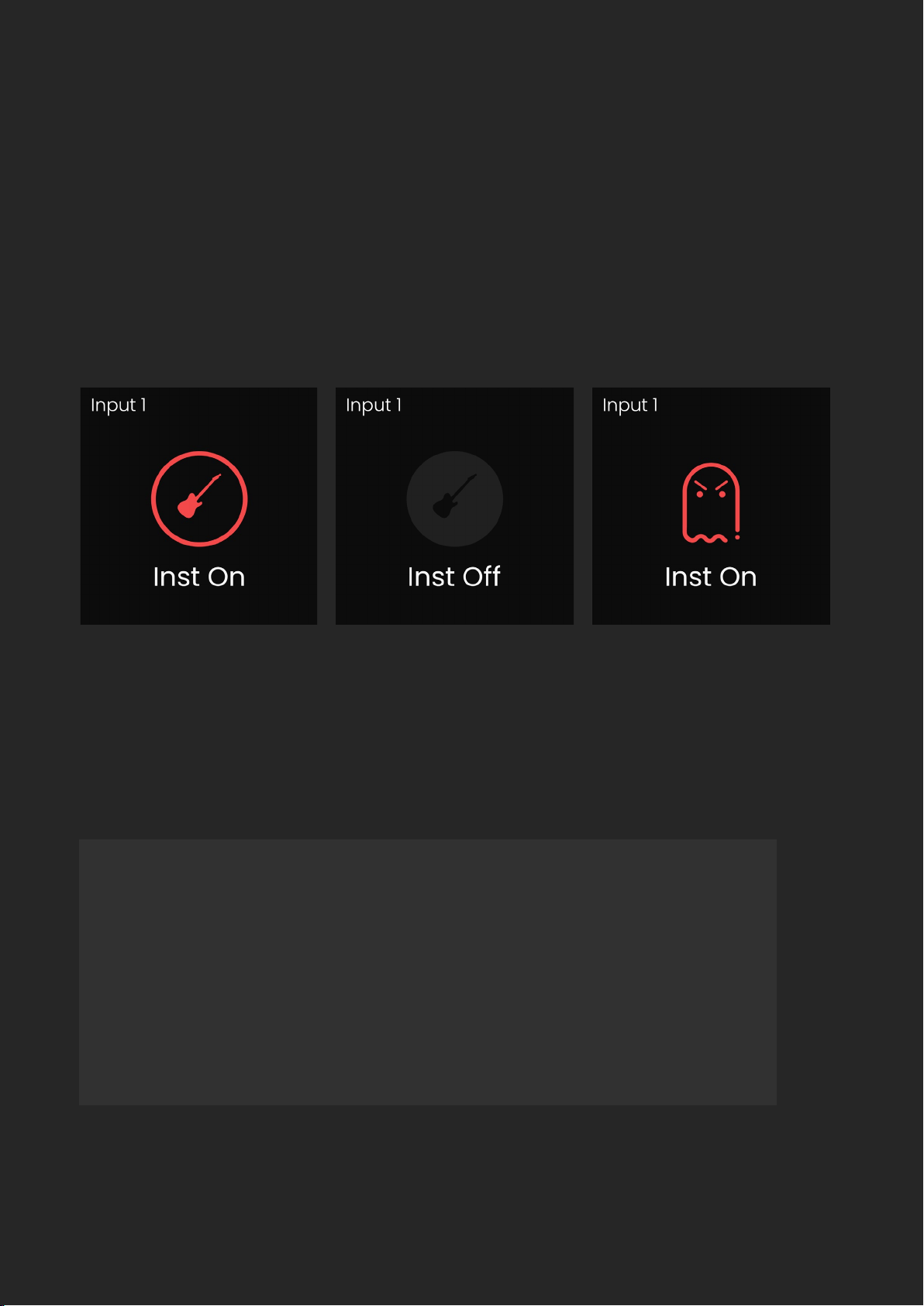
Both channels 1 + 2 are able to switch to Instrument Mode, meaning they
are able to be used to record guitars and basses. To do this, select either
channel 1 or 2, then press the Instrument Button. The button will then
illuminate as well as display the temporary feature toggle screen. To turn
o Instrument Mode, press the Instrument Button again, which will again
display the feature toggle screen.
If you try and activate phantom power on Channels 1+2 whilst the instrument
input is active, an error screen will be shown as it is not possible to have both
active at once.
Remember: After you’ve nished recording via the Instrument
Inputs, you’ll need to switch them back to line & microphone
level inputs. To do this, press whichever instrument channel
button you’re using, then press the Instrument Button.

HARDWARE
EVO SP8 has the ability to stereo link 2 channels, meaning you can match
and adjust the gain settings simultaneously. Channels can be paired in
sequential order, so channel 1 with channel 2, channel 3 with channel 4 and
so on. When two channels are linked, a ‘Link’ icon will appear on the Input
Status Screen and the input name will update. e.g. 1+2.
When on the input metering screen, you will also see a small hyphen
connecting the linked channel numbers.
The Smartgain feature can be utilised to automatically set the correct gain
levels for one or more channels simultaneously.
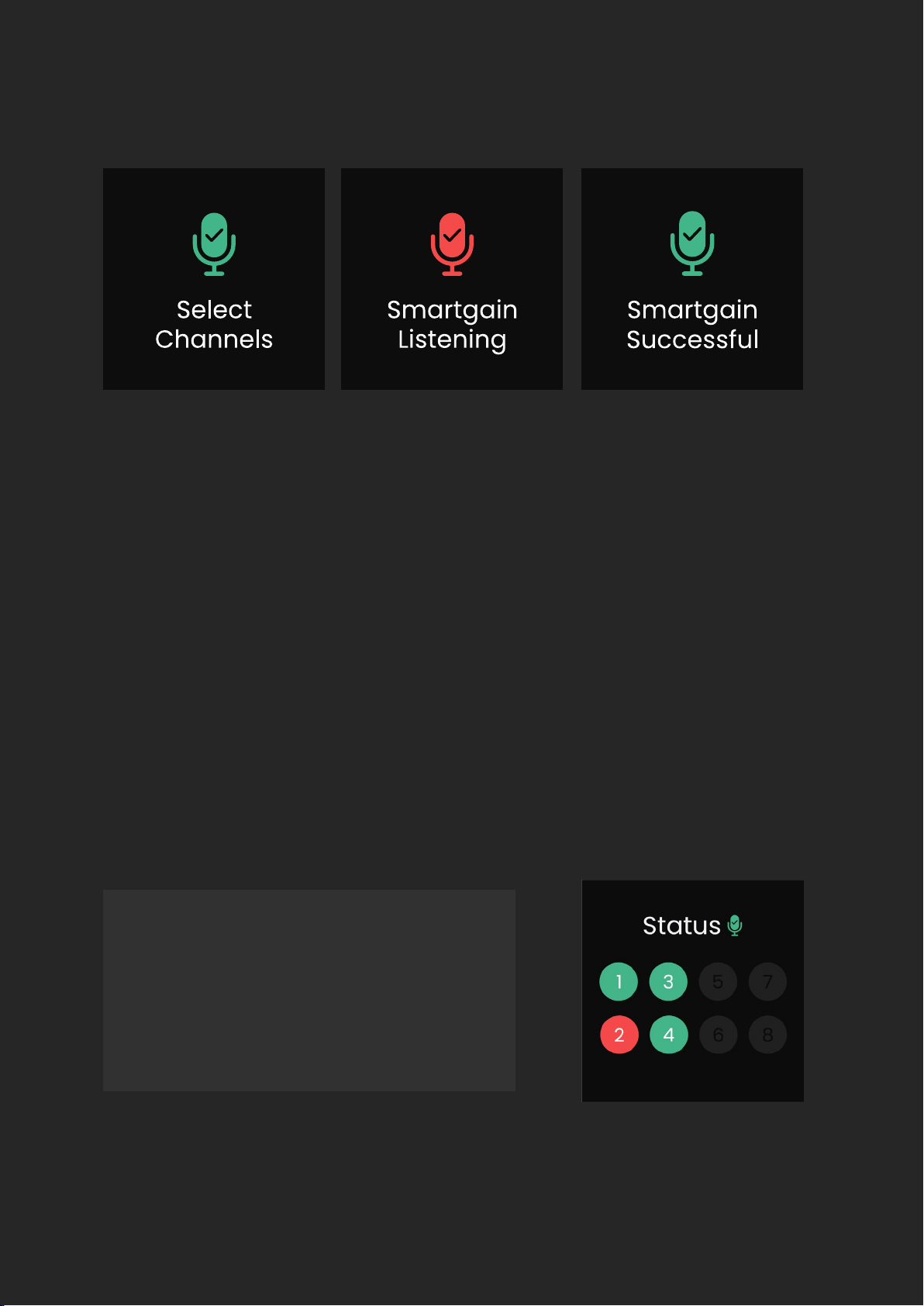
To activate Smartgain, press the green Smartgain button, you will then be
prompted to select the channels you want to set the gain for. Select the
channels you want using the channel buttons or press and hold the Smartgain
button to quickly select all 8 channels at once.
Smartgain Mode
HARDWARE
Once you have selected the channels you require, press the Smartgain Button
again to start. You will now see a ‘Smartgain Listening’ screen, this is where you
or your artist will need to start performing in order for Smartgain to analyse
your signal.
If all selected channels are successfully set, you will see the ‘Smartgain
Successful’ screen and you are ready to start recording.
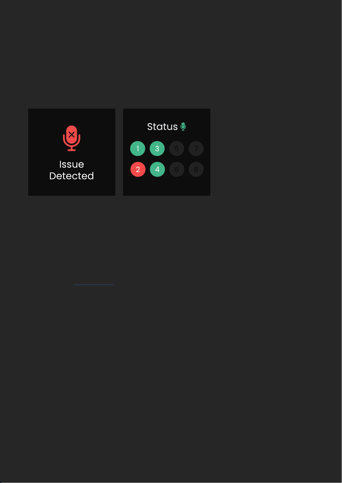
If Smartgain fails for any reason you will see the ‘Issue Detected’ screen
followed by the Smartgain Status screen. The Smartgain Status screen gives
you an overview of the status of each channel in relation to Smartgain.
Green - means it was successful
Red - means it failed
Grey - means the channel
was not selected

HARDWARE
If using one or two EVO SP8’s with an EVO 16, Smartgain can be used on all
connected EVO devices simultaneously.
Pressing the Smartgain Button on any SP8 or EVO 16 in your setup will activate
Smartgain across all devices. You can then select up to 24 channels across the
three devices to activate Smartgain on. Press the Smartgain Button again to
enter the listening period and automatically set the gain of up to 24 channels
at once!
Using Smartgain with an Extended
EVO System
Smartgain will now return you to the ‘Select Channels’ screen with the failed
channels automatically pre-selected, simply press Smartgain to start the
process again.
For the channels that failed, double-check your microphone cables, check
if phantom power is required for that microphone, or move the microphone
closer to the sound source. Then try the Smartgain process again.
Note: there is no need to select the green channels again as they were
already successfully set.
Top tip! When using Smartgain on multiple channels, ensure that every
microphone is used during the listening period. For example, if you are
micing a drum kit, ensure the drummer plays the Toms during the listening
period or else the gains for the Toms may be set incorrectly and aect your
recording.
HARDWARE
EVO SP8 also provides you with eight dedicated Line Level Outputs, which can
be found at the rear of the unit. These can either be fed from the 8 onboard EVO
Preamps (Analogue) or from the ADAT inputs (Digital) by adjusting the Output
Source in the
Setup Menu.
When set to Analogue, Preamp 1 will feed into Output 1, Preamp 2 will feed into
Output 2 and so on…
When set to Digital, ADAT Input 1 will play out of Line Output 1, ADAT Input 2 to
Line Output 2 and so on…
After the listening period, all EVO units will show the status of their 8 channels.
If any channels have failed on any device, this channel will show in a red circle
allowing you to check your mic connections on that particular device and then
try Smartgain again.
Line Outputs
HARDWARE
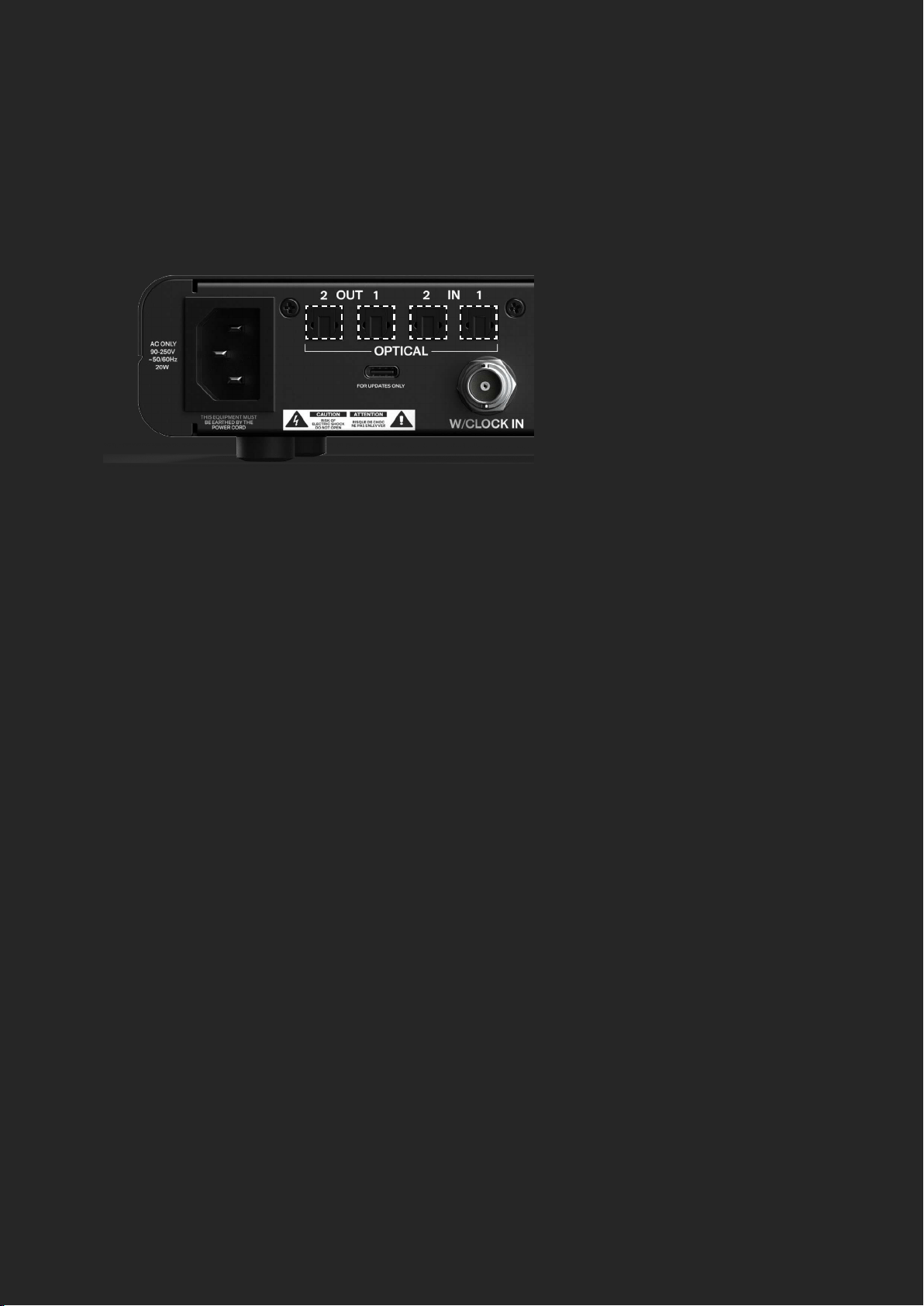
At 44.1kHz and 48kHz sample rates, you will only need to use 1 optical port for
all 8 channels, with the second port simply acting as a duplicate or split. At
88.2 and 96kHz, you will need to use both optical ports in order to access all 8
channels as higher sample rates will limit the channel count to 4 channels per
port.
The EVO SP8 also includes a BNC Word Clock Input which allows you to clock
the SP8 from another device. You can set the SP8 to use the Word Clock Input
as your Clock Source in the Setup Menu of the interface.
The Word Clock Input also has switchable 75 Ohm Termination which can be
enabled in the Setup Menu. More information about when you may need to use
75 Ohm Termination can be found in the clocking conguration section.
EVO SP8 features two Optical Inputs and two Optical Outputs that use ADAT.
This allows you to send the audio from your preamps to your host interface
as well as receive up to 8 channels and send this out via the Analogue Line
Outputs.
Digital Inputs & Outputs
Word Clock Input
Pressing and holding the Control Wheel will open the Setup Menu where you
can adjust a variety of parameters.
Setup Menu
HARDWARE
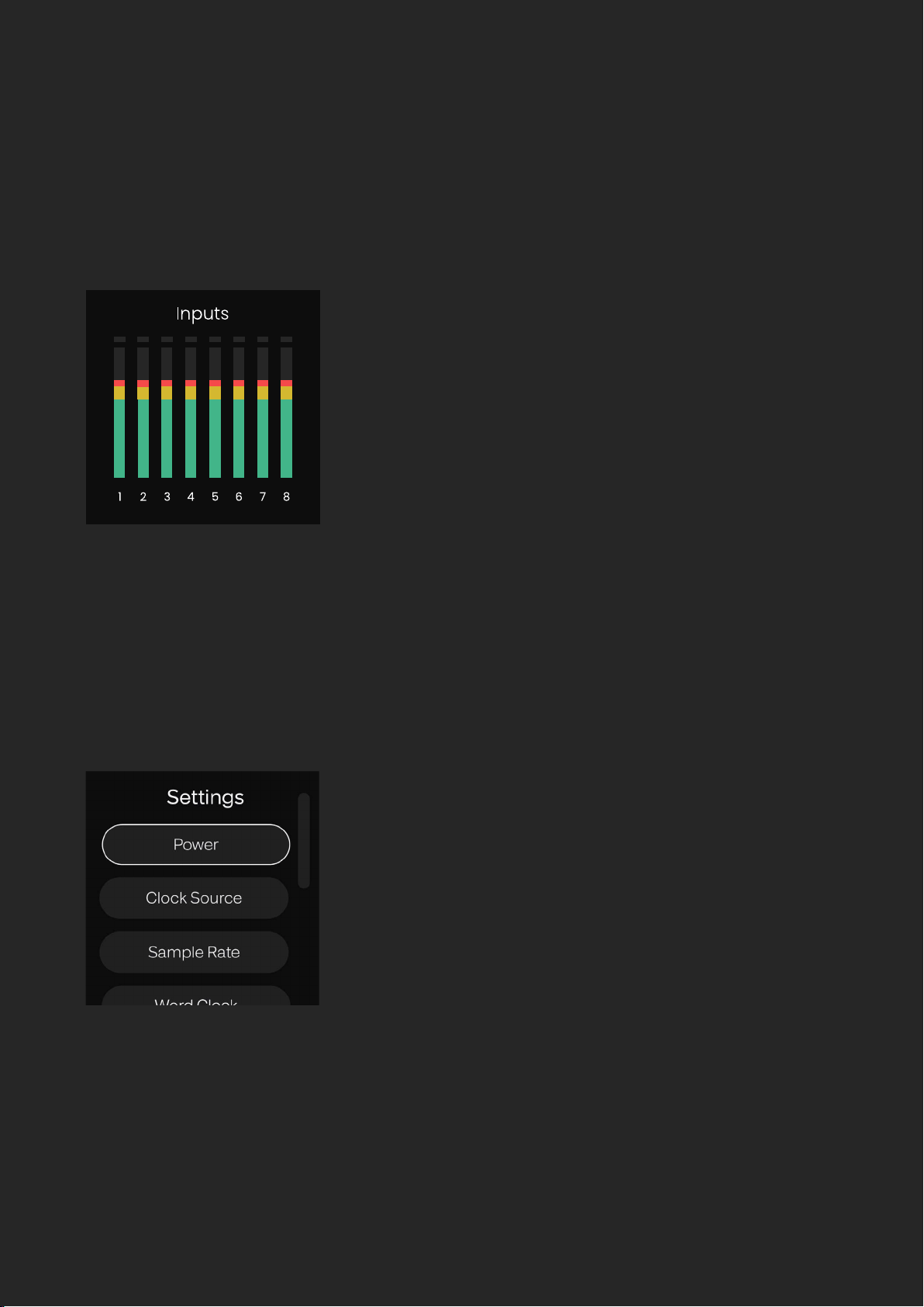
Pressing the Control Wheel lets you cycle between the metering for the 8 Preamps
and the 8 Digital Input channels so you can quickly check all your levels.
Metering
HARDWARE
Power
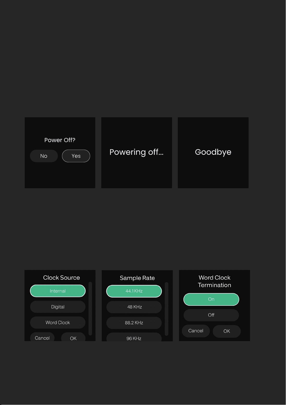
To power o the unit, rotate the Control Wheel until Power is selected,
and then press the Control Wheel to select. You will then be prompted to
conrm if you want to turn o EVO SP8, select Yes, and press the Control
Wheel to conrm.
This will put EVO SP8 in a Low-power Standby Mode. To turn the unit back
on, hold down the Control Wheel until the screen illuminates.
You can also turn o EVO SP8 without navigating to the Settings Menu by
simply holding the Control Wheel down for 5 seconds.

HARDWARE
Clock Source controls from which source the SP8 will take its clock. Internal will
use the built-in clock, Digital will take the clock from the ADAT data the unit
receives from the Optical Inputs and Word Clock takes the clock from the BNC
Word Clock Input.
When the Digital or Word Clock source is selected, the sample rate will
automatically be set to AUTO mode. This allows the SP8 to follow the sample
rate of the Clock Source.
Here you can select the sample rate you wish the device to operate at. If you are
using an external clock source (Digital or Word Clock), you can set this to AUTO
and the sample rate will be automatically adjusted to match the incoming
clock signal.
This allows you to change whether or not the Word Clock Input is terminated
or not. The Word Clock Termination should be turned on if the SP8 is the last
device in a Word Clock Chain. If you are using a BNC T-Connector to send the
clock onwards to another device then set the termination to o.
It is important to get your Word Clock Termination correct as it can stop your
devices from correctly synchronising.
Clock source
Sample rate
Word clock
HARDWARE
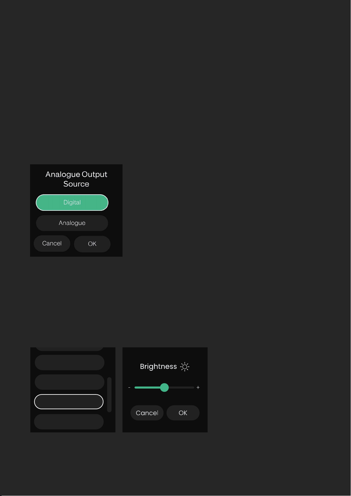
Output Source
Here you can change what signal is sent to the 8 line outputs of the EVO SP8.
When set to ‘Digital’ the 8 ADAT input channels are sent to the 8 Line Outputs
allowing the EVO SP8 to be used as a 8 channel D to A converter. Otherwise,
the ‘Analogue’ setting will send the outputs of the 8 Preamps directly to the
Line Outputs to allow the SP8 to be used as a standalone mic pre.
Brightness
Enables the brightness of the LEDs on the front panel of the EVO SP8 to be
adjusted to suit the ambience of your studio.
Brightness
Output Source
Word Clock
Status
HARDWARE
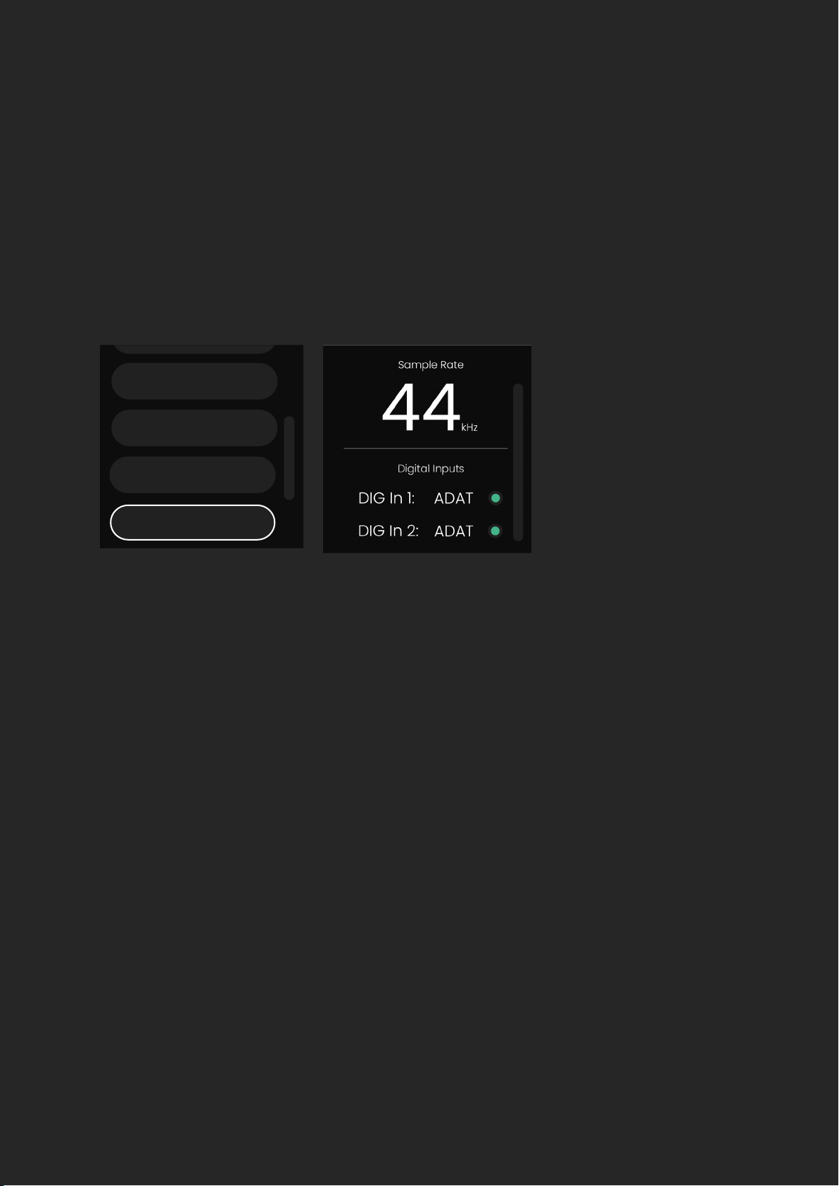
Status
The Status screen shows the current sample rate and the status of the clock
on the DIGI and Word Clock Inputs.
A green indicator dot next to an input indicates that the EVO SP8 has
successfully synced to the clock present on this input.
An amber indicator dot next to an input indicates that a valid clock has been
detected but at a dierent sample rate to the SP8’s. Adjust either the SP8 or
the external clock to match.
A red indicator dot indicates that no valid clock has been detected on this
input. In this case, double check your connections or try a dierent cable to
rule out a faulty cable.
Factory Reset
Status
Brightness
Exit
Brightness
Output Source
Word Clock
Status
HARDWARE
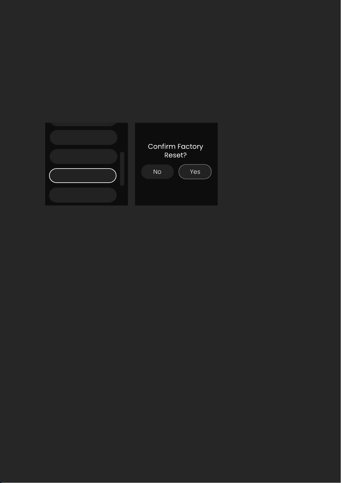
Factory Reset
Clocking Congurations
A Factory Reset will return the unit to its default state and any settings will
be removed. Please note that a factory reset cannot be undone so use this
option with care.
When you are using multiple devices together with digital connections such
as ADAT, it’s vital that they all remain in sync with each other. The process of
syncing up your devices is known as ‘clocking’.
In your setup, you must choose one device to be the primary clock and all
other devices in the system will be replica clocks. It’s important that there
is only one primary clock in your system. Having multiple primary clocks will
cause the devices to go out of sync and cause distortion on your recordings.
The primary clock sends a very fast ticking signal to the replica device. This
ticking signal can either be sent via a dedicated connection for the clock,
such as the BNC Word Clock Input on the EVO SP8, or sent alongside your
audio data on an ADAT connection.
Status
Brightness
Output Source
Factory Reset

HARDWARE
Choosing the Primary Clock Device
Channel Count per Connection
Typically, you would want to choose the device that is directly connected to the
computer to be the primary clock. This clock can then be sent to other devices
in your system using either its ADAT Outputs or a BNC Wordclock Output.
The main advantage of this is that any changes in sample rate on the computer
will automatically be sent to the other devices in the setup and everything will
remain in sync.
Otherwise, you can use the SP8 as the primary clock instead. This would send
the clock to another device via its ADAT Outputs. This can only be done on
simple setups (1x EVO SP8 and 1x EVO 16 for example) but when more devices
are involved, it’s best to make use of a BNC Word Clock connection.
At sample rates of 44.1 and 48kHz, each optical connection will carry 8 ADAT
channels. When the sample rate is increased to 88.2kHz or 96kHz, this channel
count drops due to how the ADAT protocol works. At these higher sample rates,
two TOSlink cables per connection will be required to access all 8 channels.
EVO SP8 does not support 176.4 or 192kHz sample rates.
Key:
Optical TOSlink Cable BNC Word Clock Cable
EVO EXPANDED SYSTEM
EVO EXPANDED SYSTEM
Using one or two EVO SP8’s alongside an EVO 16 creates an EVO Expanded
System, enabling you to take advantage of features reserved only for this
conguration. For example, this system provides a powerful platform as
you can utilise up to 24 channels of Smartgain simultaneously, all of which
can all be controlled from one unit.
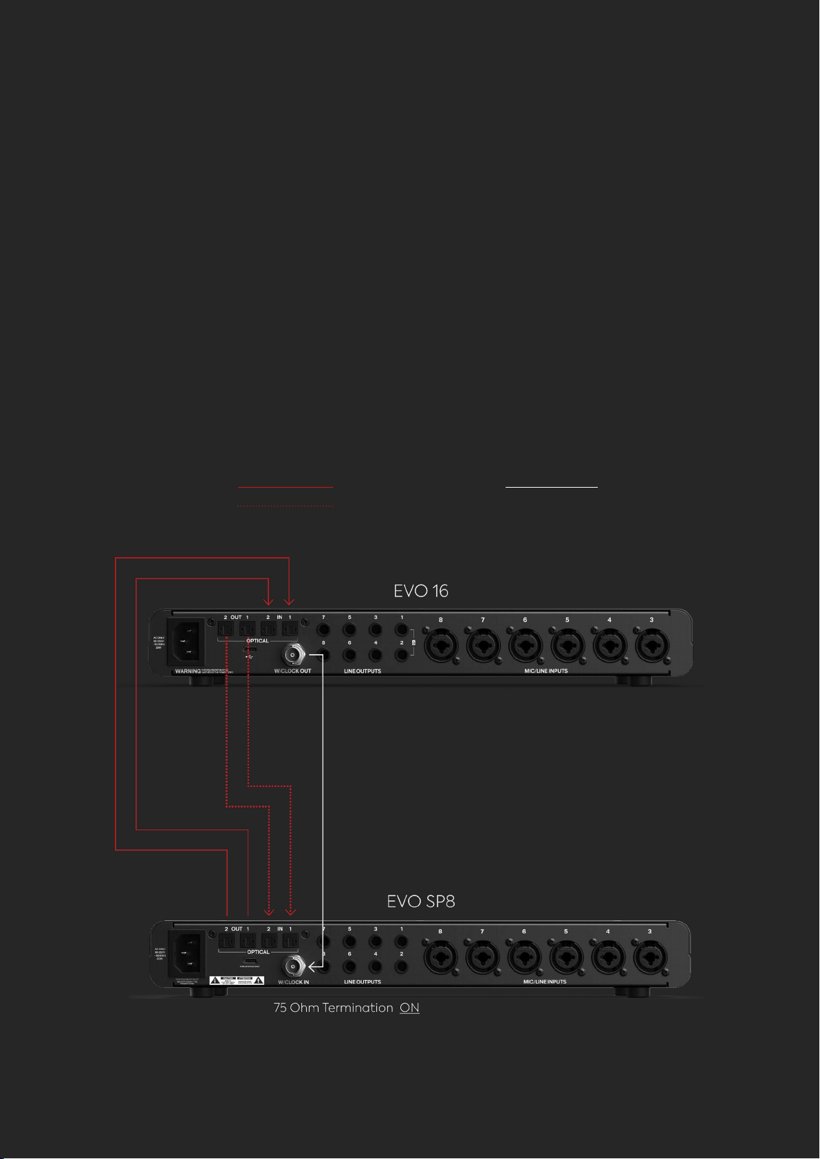
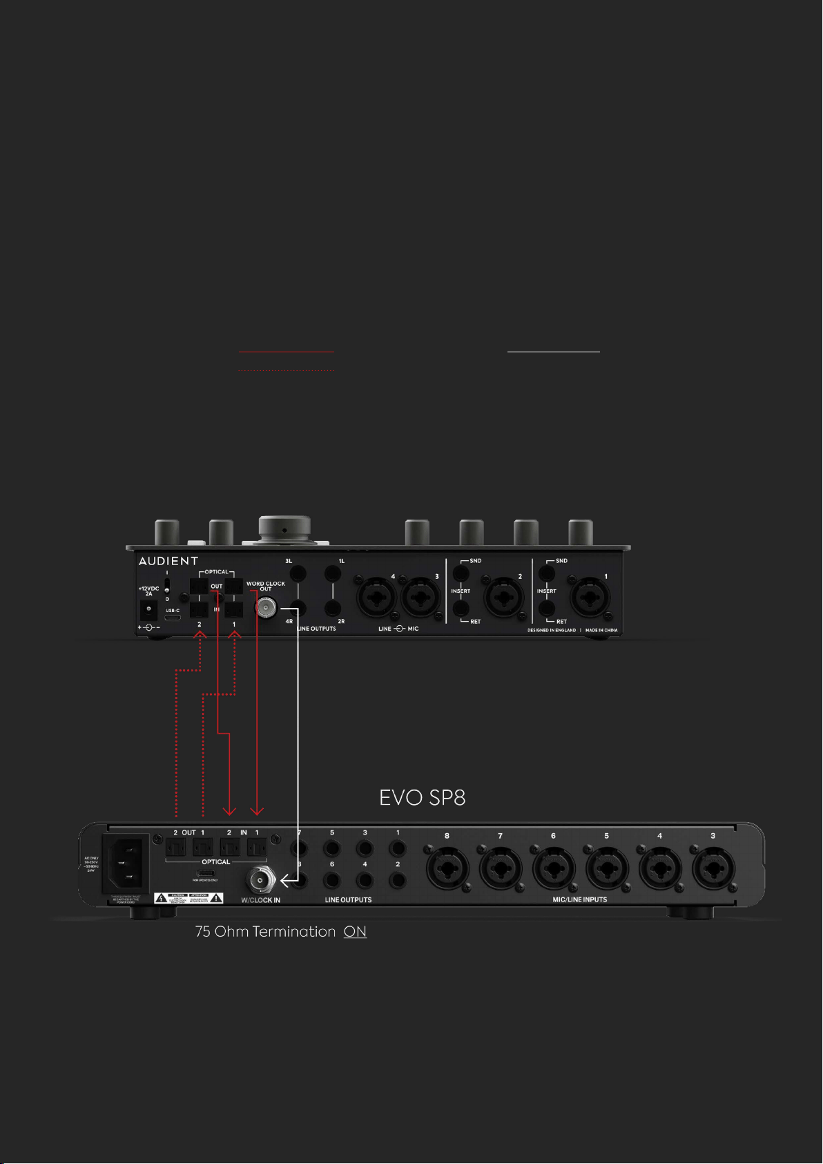
1 x EVO SP8 and 1 x EVO 16

EVO EXPANDED SYSTEM
Connect the Optical Outputs of the EVO 16 to the Optical Inputs of
the EVO SP8 using two TOSlink cables.
Connect the Optical Inputs of the EVO 16 to the Optical Outputs on
SP8 using two further TOSlink cables.
Connect the Word Clock Output of the EVO 16 to the Word Clock Input
of the SP8.
In the setup menu of the EVO SP8, ensure that your clock source is set
to ‘Word Clock’ and the Word Clock Termination is turned on. Also set
the Sample Rate to ‘Auto’.
On the EVO 16, ensure that its clock source is set to ‘Internal’ and the
Optical format is set to ‘ADAT’ in the EVO Mixer Application’s System
Panel.
1.
2.
3.
4.
5.
Key:
Optical TOSlink Cable BNC Word Clock Cable
EVO EXPANDED SYSTEM
Using the One or Two EVO SP8 alongside an EVO 16 provides a powerful
platform as you have up to 24 channels of Smartgain which can all be
controlled from one unit.
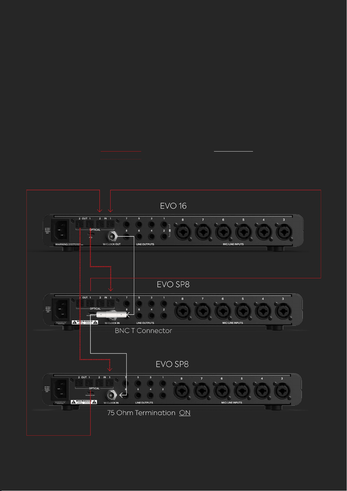
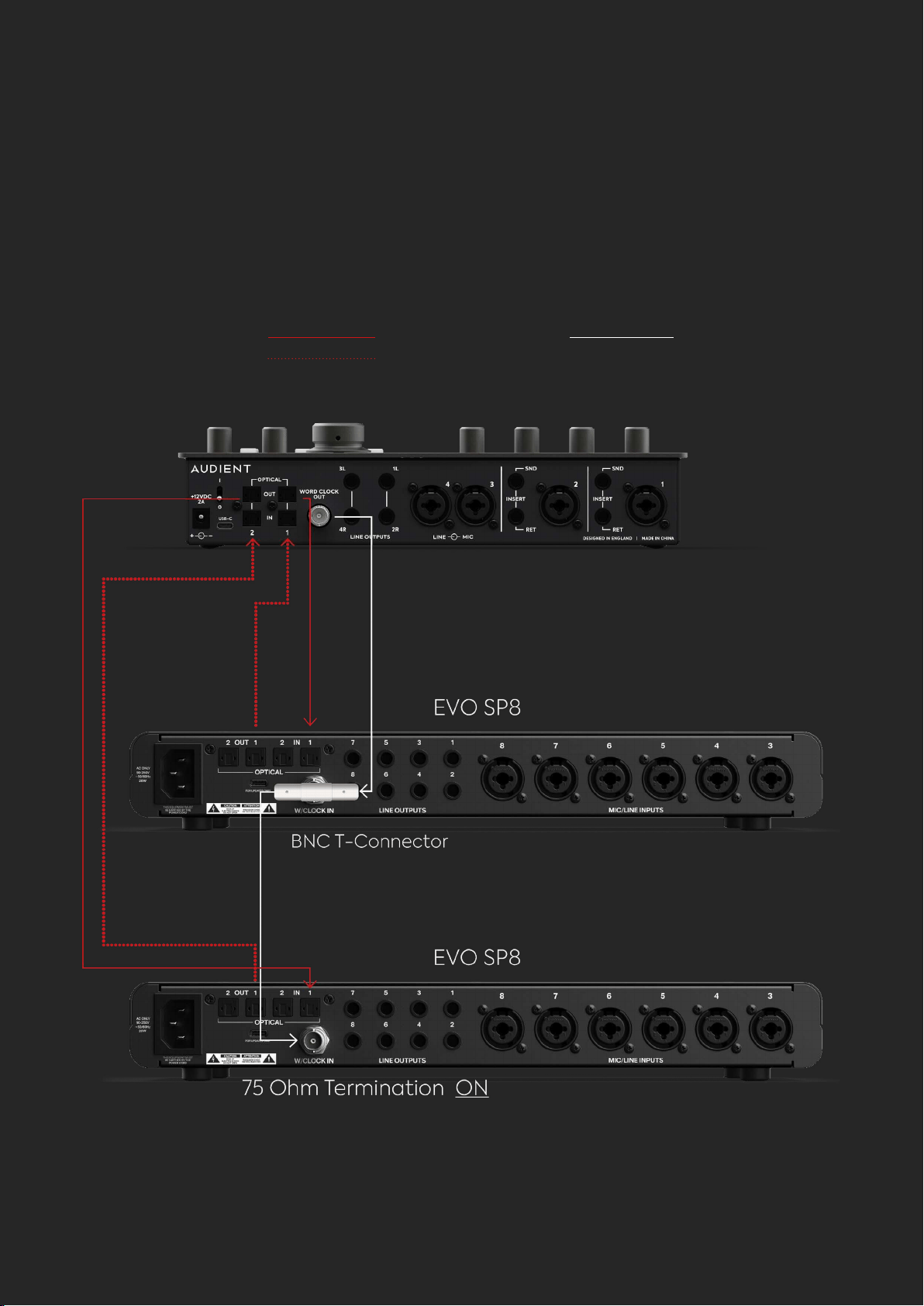
2 x EVO SP8 and 1 x EVO 16

EVO EXPANDED SYSTEM
Connect the rst Optical Output of the EVO 16 to the Optical Input of
the rst EVO SP8 and the second optical Output of the EVO 16 to the
rst Optical input of the second EVO SP8. This will require two TOSlink
cables.
Connect the Optical Inputs of the EVO 16 to the Optical Outputs of
the EVO SP8’s, in the same manner, using a further two TOSlink cables.
Connect a BNC T-Bar connector to the Word Clock Input of the rst
SP8.
Connect a BNC word clock cable from the Word Clock Output of the
EVO 16 into one side of the T-Connector.
Connect a second word clock cable from the other side of the
T-Connector into the Word Clock Input of the second EVO SP8.
On both SP8s use the Setup Menu to set the clock source to ‘Word
Clock’. On the rst SP8, set the Word Clock Termination to ‘O’. On
the second SP8, set the Word Clock Termination to ‘On’. Also set the
Sample Rate to ‘Auto’ on both units
On the EVO 16, ensure that its clock source is set to ‘Internal’ and the
Optical format is set to ‘ADAT’ in the EVO Software Mixer Application’s
System Panel.
1.
2.
3.
4.
5.
6.
7.
Key:
Optical TOSlink Cable
EVO EXPANDED SYSTEM
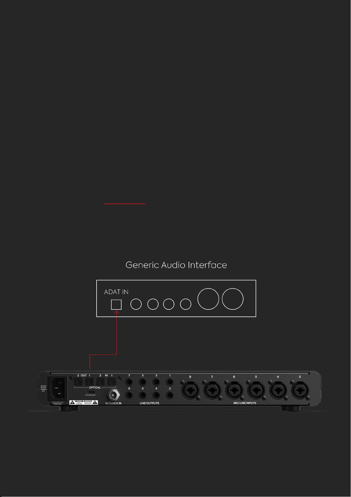
If your host interface doesn’t have a Word Clock Output, such as an Audient
iD14, you can use the SP8 as the primary clock.
EVO SP8 as the Primary Clock
USING EVO SP8 WITH AN
ADAT CAPABLE INTERFACE

EVO EXPANDED SYSTEM
Connect an TOSlink cable from the EVO SP8’s Optical Output to the
Optical Input of your host interface.
Using the Setup Menu of the SP8, set the clock source to ‘Internal’.
Check that your host interface is set up to sync to the incoming ADAT
signal. On an Audient iD interface for example, this would be done in
the System Panel by setting the Clock Source to ‘DIGI’.
Finally, check that both devices are using the same sample rate so
they can correctly sync.
1.
2.
3.
4.
Key:
Optical TOSlink Cable BNC Word Clock Cable
EVO EXPANDED SYSTEM
If your host input has a Word Clock Output then you can use this as your
primary clock and the SP8 as the replica. An example of this would be an
Audient iD44 MKII.
1 x EVO SP8 as a Replica

Please note that if your host interface only has one optical
port per connection then you can use just one TOSlink cable
per connection. However, this will limit your channel count to 4
channels at 88.2 and 96 kHz .
EVO EXPANDED SYSTEM
Connect the Optical Outputs of the host interface to the Optical
Inputs of the EVO SP8 using two TOSlink cables.
Connect the Optical Inputs of the host Interface to the Optical
Outputs on SP8 using two further TOSlink cables.
Connect the Word Clock Output of the host interface to the Word
Clock Input of the SP8.
In the Setup Menu of the EVO SP8, ensure that your clock source is set
to ‘Word Clock’ and the Word Clock Termination is turned on. Also set
the Sample Rate to ‘Auto’.
On the Host Interface, ensure that its clock source is set to “Internal”
and the Optical format is set to ‘ADAT’.
1.
2.
3.
4.
5.
Key:
Optical TOSlink Cable BNC Word Clock Cable
EVO EXPANDED SYSTEM
2 x EVO SP8 as Replicas

EVO EXPANDED SYSTEM
Connect the rst Optical Output of the host interface to the Optical
Input of the rst EVO SP8 and the second Optical Output of the host
interface to the rst Optical Input of the second EVO SP8. This will use
2 TOSlink cables.
Connect the Optical Inputs of the host interface to the Optical Outputs
of the EVO SP8s, in the same manner, using a further 2 TOSlink cables.
Connect a BNC T-Bar connector to the Word Clock Input of the rst
SP8, the part with the rotating barrel should lock onto the SP8.
Connect a BNC word clock cable from the Word Clock Output of the
host interface into one side of the T-Connector.
Connect a second word clock cable from the other side of the
T-Connector into the Word Clock Input of the second EVO SP8.
On the host interface, ensure that its clock source is set to ‘Internal’.
On both SP8s use the Setup Menu to set the clock source to ‘Word
Clock’. On the rst SP8, set the Word Clock Termination to ‘O’. On
the second SP8, set the Word Clock Termination to ‘On’. Also set the
Sample Rate to ‘Auto’ on both units.
1.
2.
3.
4.
5.
6.
7.
RACK MOUNTING
EVO SP8 RACK MOUNTING
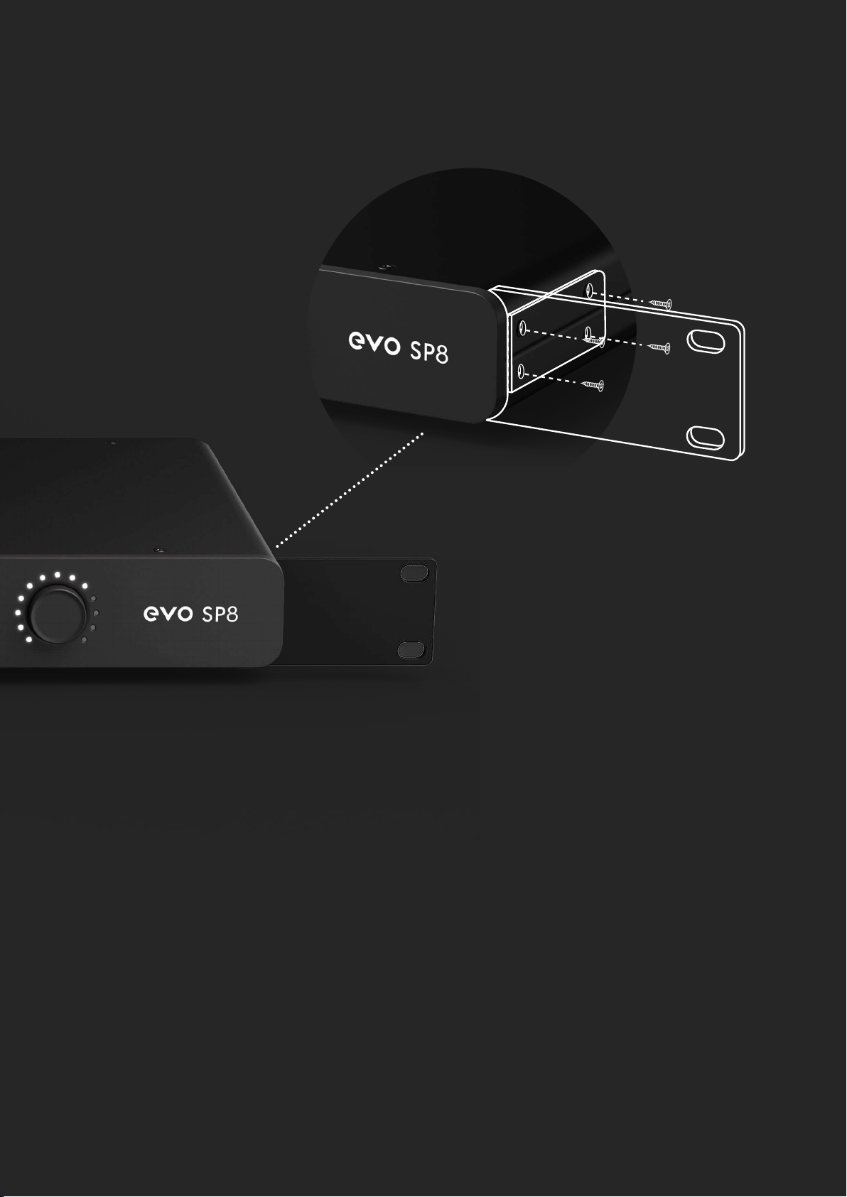
EVO SP8 can be tted with optional Rack Ears which can be purchased from
your dealer. These can be attached to the sides of the unit with the contained
screws.
The following items are provided with an EVO SP8 Rack Ear Kit (check within
packaging):
4 x M4 Screws
2 x EVO Rack Ears
1. Use a 3mm hex driver to remove the two screws either side near the front
of the unit.
2. Position Rack Ear so that the four screw holes are inline with the four
screw holes found on the side of the EVO SP8. Refer to the image above for
correct positioning.
3. Insert the 4 x M4 screws into the holes and tighten until rm.
4. Remove the rubber feet which are located on the bottom of the EVO SP8
using a Pozidriv screwdriver.
How to install the Rack Ears
RACK MOUNTING
It is not advised to run the unit in a rack above or below hot units such as valve
outboard and multichannel AD/DA converters without suitable ventilation space
around the unit.
We would suggest a space of at least one rack unit above and below the unit.
Additionally, do not install near any heat sources such as radiators, heat registers,
stoves or other apparatus (including ampliers) that produce heat.
Caution regarding rack placement
Required:
3mm Hex Driver/Key
Pozidriv Screwdriver


SPECIFICATIONS
SPECIFICATIONS
Phantom Power:
INPUT IMPEDANCE:
48v +/-4v @ 10mA/Channel
500k
CMRR:
THD+N @ 0dBu (1kHz):
>80dB @ 1kHz
<0.1%
Maximum Input Level: +16dBu
Input Impedance (Mic): >3kΩ Balanced
Input Impedance (Line):
>10kΩ Balanced
Frequency Response: +/-0.5dB 10Hz to 40kHz
Crosstalk: <-105dBu @ 1kHz <-103 @ 10kHz
THD+N @ 0dBu (1kHz):
SNR:
SNR:
<0.0015%
100dB
Mic EIN: <-127.5dBu
XLR:
1/4” Jack:
Pin 2 (Hot), Pin 3 (Cold) & Pin 1 (Shield)
TIP (Hot), RING (Cold) & SLEEVE (Shield)
MICROPHONE PREAMPLIFIER:
Mic Gain Range: 58 dB
Line Gain Range: 58dB with -10dB Pad
D.I Gain Range:
MAXIMUM INPUT LEVEL:
FREQUENCY RESPONSE:
58dB
+10dBu
100dB
1/4” JACK: TIP (Hot) & SLEEVE (Shield)
+/-0.5dB 10Hz to 20kHz

DIGITAL TO ANALOGUE CONVERTER
Maximum Output Level:
Digital Reference Level:
12dBu
0dBFS = +10.5dBu
Digital Reference Level:
Frequency Response:
0dBFS = +12dBu
+/-0.5dB 10Hz to Fs/2
Output Impedance:
Crosstalk:
<50Ω
-125dBu @ 1kHz & 10kHz
Frequency Response:
THD+N @ -1dBFS (1kHz):
+/-0.5dB 10Hz to Fs/2
<0.001%
Crosstalk:
Dynamic Range:
<-110dBu @ 1kHz
112.5dB A-Weighted
THD+N @ -1dBFS (1kHz): <0.006%
Dynamic Range: 117dB A-weighted
1/4” Jack: TIP (Hot), RING (Cold) & SLEEVE (Shield)
ANALOGUE TO DIGITAL CONVERTER

WARRANTY INFORMATION
Your EVO SP8 comes with a manufacturer’s warranty for three years (36 months)
from the date of despatch to the end user.
The warranty covers faults due to defective materials used in manufacture and
faulty workmanship only.
During the warranty period Audient will repair or at its discretion replace the faulty
unit provided it is returned carriage paid to an authorised Audient service centre.
We will not provide warranty repair if in our opinion the fault has resulted from
unauthorised modication, misuse, negligence or accident.
We accept liability to repair or replace your EVO SP8 as described above. We do
not accept any additional liability. This warranty does not aect any legal rights
you may have against the person who supplied this product - it is additional to
those rights.
Warranty Statement
Warranty Limitations
WARRANTY
This warranty does not cover damage resulting from accident or misuse.
The warranty is void unless repairs are carried out by an authorised service centre.
The warranty is void if the unit has been modied other than at the manufacturer’s
instruction.
The warranty does not cover components which have a limited life, and which are
expected to be periodically replaced for optimal performance.
We do not warrant that the unit shall operate in any other way than as described
in this manual.

Tel: 0044 1256 381944
IMPORTANT SAFETY INSTRUCTIONS
• Read instructions - All the safety and operating instructions should be read
before the product is operated.
• Retain instructions - The safety and operating instructions should be retained
for future reference.
• Heed Warnings - All warnings on the product and in the operating instructions
should be adhered to.
• Follow Instructions - All operating and use instructions should be followed.
• Cleaning - Unplug this product from the wall outlet before cleaning. Do not
use liquid cleaners or aerosol cleaners. Use a dry cloth for cleaning.
• Attachments - Do not use attachments not recommended by the product
manufacturer as they may cause hazards.
• Water and Moisture - Do not use this product near water-for example, near a
bath tub, wash bowl, kitchen sink, or laundry tub; in a wet basement; or near a
swimming pool; and the like.
• Accessories - Do not place this product on an unstable cart, stand, tripod,
bracket, or table. The product may fall, causing serious injury to a child or adult
and serious damage to the product. Any mounting of the product should
follow the manufacturer’s instructions, and should use a mounting accessory
recommended by the manufacturer.
• Flame Sources - No naked ame sources, such as lighted candles, should be
placed on the product.
SAFETY INSTUCTIONS

• Ventilation - Slots and openings in the cabinet are provided for ventilation
to ensure reliable operation of the product and to protect it from overheating.
These openings must not be blocked or covered. The openings should never
be blocked by placing the product on a bed, sofa, rug, or other similar surface.
This product should not be placed in a built-in installation such as a bookcase
or rack unless proper ventilation is provided or the manufacturer’s instructions
have been adhered to.
• Power Sources - This product should be operated only from the type of power
source indicated on the marking label and connected to a MAINS socket outlet
with a protective earthing connection. If you are not sure of the type of power
supply to your home, consult your product dealer or local power company.
• Power-Cord Protection - Power-supply cords should be routed so that they
are not likely to be walked on or pinched by items placed upon or against them,
paying particular attention to cords at plugs, convenience receptacles, and
the point where they exit from the product.
• Mains Plug - Where the mains plug or an appliance coupler is used as the
disconnect device, the disconnect device shall remain readily operable.
• Lightning - For added protection for this product during a lightning storm, or
when it is left unattended and unused for long periods of time, unplug it from
the wall outlet and disconnect the antenna or cable system. This will prevent
damage to the product due to lightning and power-line surges.
• Power Lines - An outside antenna system should not be located in the vicinity
of overhead power lines or other electric light or power circuits, or where it can
fall into such power lines or circuits. When installing an outside antenna system,
extreme care should be taken to keep from touching such power lines or circuits
as contact with them might be fatal.
• Overloading - Do not overload wall outlets, extension cords, or integral
convenience receptacles as this can result in a risk of re or electric shock.
SAFETY INSTUCTIONS

• Object and Liquid Entry - Never push objects of any kind into this product
through openings as they may touch dangerous voltage points or short-out
parts that could result in a re or electric shock. Never spill liquid of any kind on
the product.
• Headphones - Excessive sound pressure form earphones and headphones
can cause hearing loss.
• Damage Requiring Service - Unplug this product from the wall outlet and
refer servicing to qualied service personnel under the following conditions:
– When the power-supply cord or plug is damaged.
– If liquid has been spilled, or objects have fallen into the product.
– If the product has been exposed to rain or water.
– If the product does not operate normally by following the operating
instructions. Adjust only those controls that are covered by the operating
instructions as an improper adjustment of other controls may result in
damage and will often require extensive work by a qualied technician to
restore the product to its normal operation.
– If the product has been dropped or damaged in any way.
– When the product exhibits a distinct change in performance-this indicates a
need for service.
• Replacement Parts - When replacement parts are required, be sure the
service technician has used replacement parts specied by the manufacturer
or have the same characteristics as the original part. Unauthorized substitutions
may result in re, electric shock, or other hazards.
• Battery Disposal - When disposing of used batteries, please comply with
governmental regulations or environmental public instruction’s rules that apply
in your country or area.
• Safety Check - Upon completion of any service or repairs to this product, ask
the service technician to perform safety checks to determine that the product
is in proper operating condition.
SAFETY INSTUCTIONS

THE LIGHTNING FLASH WITH ARROWHEAD SYMBOL, WITHIN
AN EQUILATERAL TRIANGLE, IS INTENDED TO ALERT THE
USER TO THE PRESENCE OF UNINSULATED “DANGEROUS
VOLTAGE” WITHIN THE PRODUCT’S ENCLOSURE THAT MAY
BE OF SUFFICIENT MAGNITUDE TO CONSTITUTE A RISK OF
ELECTRIC SHOCK TO PERSONS.
THE EXCLAMATION POINT WITHIN AN EQUILATERAL TRIANGLE
IS INTENDED TO ALERT THE USER TO THE PRESENCE OF
IMPORTANT OPERATING AND MAINTENANCE (SERVICING)
INSTRUCTIONS IN THE LITERATURE ACCOMPANYING THE
APPLIANCE.
WARNING
SAFETY INSTUCTIONS

CAUTION REGARDING PLACEMENT
To maintain proper ventilation, be sure to leave a space around the unit (from
the largest outer dimensions including projections) than is equal to, or greater
than shown below.
It is not advised to run the unit in a rack above hot units such as valve outboard
and multichannel AD/DA converters without suitable ventilation space around
the unit. Ensure side air vents are not covered.
Left and Right Panels: 10 cm
Rear Panel: 10 cm
Top Panel: 10 cm
DO NOT install near any heat sources such as radiators, heat registers, stoves,
or other apparatus (including ampliers) that produce heat.
DO NOT defeat the safety purpose of the polarized or grounding - type plug. A
polarized plug has two blades with one wider than the other. A grounding type
plughas two blades and a third grounding prong. The wide blade or the third
prong is provided for your safety. When the provided plug does not t into your
outlet, consult an electrician for replacement of the obsolete outlet.
SAFETY INSTUCTIONS
Tel: 0044 1256 381944 support@evo.audio.com support.audient.com

FCC STATEMENT
This equipment has been tested and found to comply with the limits for Class
B digital device, pursuant to Part 15 of the FCC Rules. These limits are designed
to provide reasonable protection against harmful interference in a residential
installation. This equipment generates, uses, and can radiate radio frequency
energy and, if not installed and used in accordance with the instructions, may
cause harmful interference to radio communications. However, there is no
guarantee that interference will not occur in a particular installation. If this
equipment does cause harmful interference to radio or television reception,
which can be determined by turning the equipment o and on, the user is
encouraged to try to correct the interference by one or more of the following
measures:
• Reorient or relocate the receiving antenna.
• Increase the separation between the equipment and receiver.
• Connect the equipment into an outlet on a circuit dierent from that to
which the receiver is connected.
• Consult the dealer or an experienced radio TV technician for help.
• This device complies with Part 15 of the FCC Rules. Operation is subject to the
following two conditions:
1 this device may not cause harmful interference, and
2 this device must accept any interference received, including interference
that may cause undesired operation.
• To prevent electric shock, match wide blade of plug to wide slot, fully insert
(Applies only to devices that uses plug with wide blade).
• For the appliance provided with a protective earth terminal should be
connected
to a mains outlet with a protective earth connection.
• Mains plug is used as disconnect device and it should remain readily operable
during intended use. In order to disconnect the apparatus from the mains
completely, the mains plug should be disconnected form the mains socket
outlet completely.
• Marking and rating plate are located at the back or bottom of the apparatus.