Loading ...
Loading ...
Loading ...

13
Power Switch and unplug the charger from the AC power source. Then, disconnect the charger clamp not con-
nected directly to the battery first and DO NOT allow the clamp to touch anything. Then, disconnect the charger
clamp attached to the battery terminal. (See Connecting To Batteries... at the beginning of this section.)
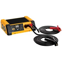
Power Supply Mode Operation
ATTENTION: Do not plug the charger power cord into the AC power source or set any of the charger’s controls
until told to do so in the following instructions.
ATTENTION: Verify output cable connectors are properly seated and locked in place.
ATTENTION: Connect and disconnect DC output clamps only after setting the power switch to the “OFF” position
and unplugging the AC cord from electric outlet. Never allow clamps to touch each other.
ATTENTION: Do not operate the charger in a closed area or restrict ventilation in any way. Ensure that there that
there are no obstructions to the air flow, so the internal fans can properly cool the unit.
Upon checking that your output cables are properly seated and locked into the unit, make a proper battery
connection (see Connecting to a Battery in a Vehicle Section) and plug AC power cord into an AC receptacle. Then,
turn the master power switch located on the back of the unit to ON. The charger is now in Standby Mode.
In order to place the unit into Power Supply Mode, toggle the Mode Selection button until the SUPPLY LED is
lit. If an ERROR Indicator LED lights, disconnect from AC power supply immediately and determine the cause of
the alarm. The POLARITY light indicates reverse polarity error connection, while the ERROR light indicates the
detection of a battery fault, such as a shorted connection.
NOTE: Make sure that the vehicle battery is in good condition and fully charged. A compromised battery can
jeopardize your programming event. The unit will not commence the Power Supply mode if the vehicle battery is
below 12.0VDC. Charge the battery first to ensure it is capable of supporting a programming event.
1. Choose the desired system voltage level. Using the UP/DOWN arrows in the Power Supply mode voltage control
zone, set the system voltage level on the display to the desired voltage.
2. Press the START button. The charger will bring system voltage to the desired level and hold it at that level,
providing power as needed (to a maximum of 100A) to the vehicle to maintain the desired level. If you press
the START button at any point during the Power Supply sequence, the charger will stop charging and return to
Standby Mode.
3. After the Power Supply session is complete, press the START button to return the unit to Standby Mode,
turn off the Master Power Switch and unplug the charger from the AC power source. Then, disconnect the
charger clamp not connected directly to the battery first and DO NOT allow the clamp to touch anything. Then,
disconnect the charger clamp attached to the battery terminal. (See Connecting To Batteries... at the beginning
of this section.)
Charging Amp Settings
Model Number Operating Voltage Charging Rate Power Supply Max Output
PL6100 12V 60/40/10A 100A
Loading ...
Loading ...
Loading ...