Loading ...
Loading ...
Loading ...
UTILITY
UPS
UPS
AVAILABLE
MAINTENANCE BYPASS
AVAILABLE
A
B
C
A
E
E
D
UTILITY
UPS
UPS
AVAILABLE
MAINTENANCE BYPASS
AVAILABLE
UPS
UTILITY
ASS
UTILITY
UPS
UPS
AVAILABLE
MAINTENANCE BYPASS
AVAILABLE
A
B
B
6
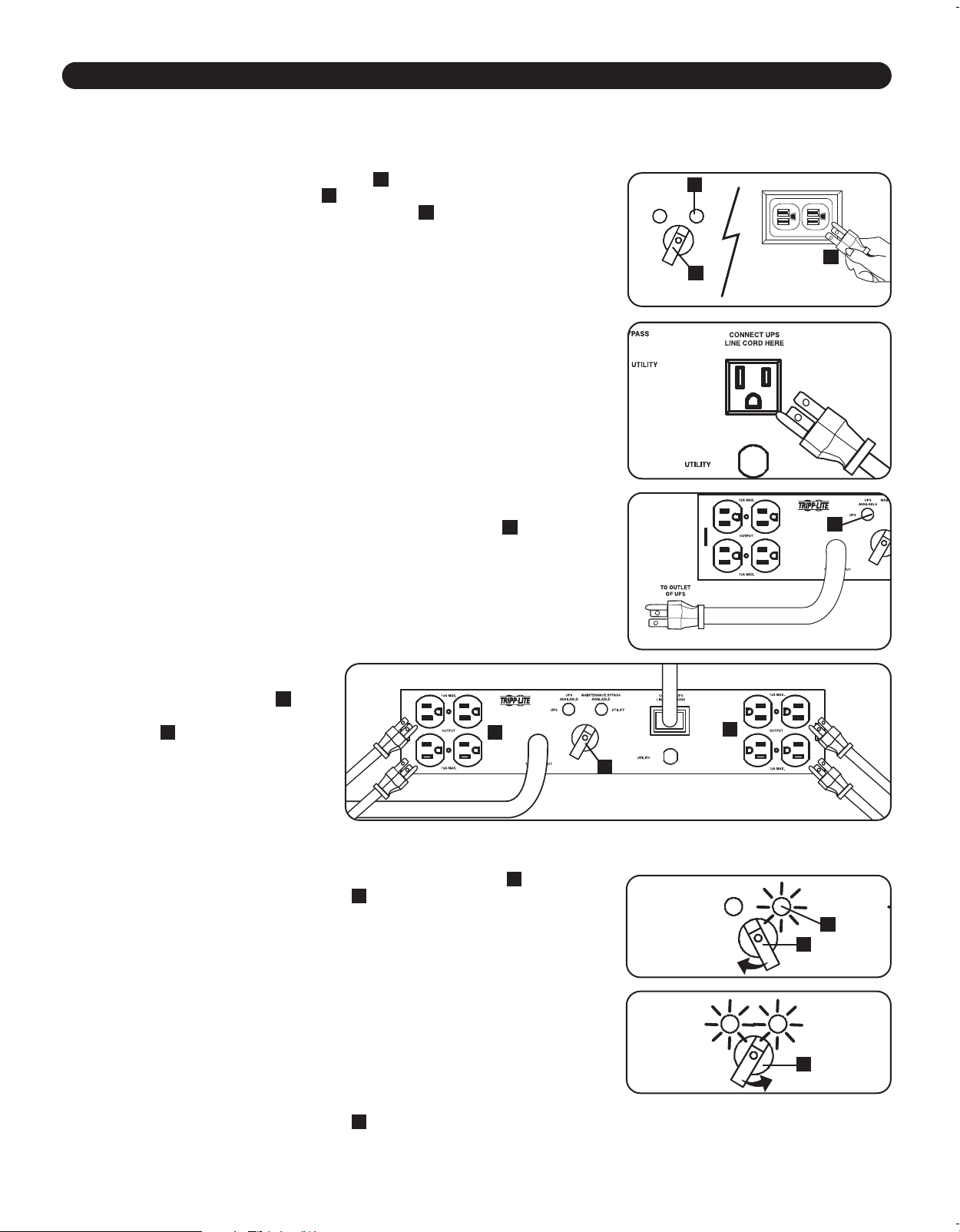
Connection & Operation
Input/Output Power Connections
Step 1. Shut down the equipment plugged into the UPS system and unplug the equipment cables from the UPS system.
Step 2. Shut down the UPS system and unplug it from the utility source.
Step 3. Set the PDU’s Maintenance Bypass Switch
A
to the “Utility” position and connect
the PDU’s utility source input cord
B
to your facility’s utility AC power source. The
PDU’s yellow “Maintenance Bypass Available” light
C
will illuminate.
Step 4. Connect the UPS system’s input power cord to the PDU’s UPS connection outlet
(labeled “Connect UPS Line Cord Here”) and turn on the UPS system.
Step 5. Connect the PDU’s UPS source input cord (labeled “To UPS Output”) to a compatible
outlet on the UPS system. The PDU’s green “UPS Available” light
D
will illuminate.
Step 6. Connect the equipment cables
to compatible PDU outlets
E
and
set the Maintenance Bypass
Switch
A
to the “UPS” position.
The connected load now has UPS
protection.
Manual Bypass Operation For Hot-Swap UPS Replacement
Step 1. Make sure the PDU’s yellow “Maintenance Bypass Available” light
A
is illuminated.
Switch the Maintenance Bypass Switch
B
from “UPS” to “Utility”. The connected
load is now being supported by the utility power source and will not receive battery
backup power in the event of a utility power failure.
Step 2. Turn off the UPS system that requires maintenance or replacement and remove all
power connections between the UPS system and the PDU. The PDU’s green “UPS
Available” light will be off.
Step 3. Replace the UPS system. Connect the new UPS system’s input power cord to the
PDU’s UPS connection outlet (labeled “Connect UPS Line Cord Here”) and turn on
the new UPS system.
Step 4. Connect the PDU’s UPS source input cord (labeled “To UPS Output”) to a
compatible outlet on the new UPS system. The PDU’s green “UPS Available” light
will illuminate.
Step 5. Switch the Maintenance Bypass Switch
B
from “Utility” to “UPS”. The connected
load is now has UPS protection.
Step 3
Step 4
Step 5
Step 6
Models vary.
Models vary.
Models vary.
Models vary.
Step 1
Step 5
21-03-392- 932933.indb 621-03-392- 932933.indb 6 4/1/2021 11:19:48 AM4/1/2021 11:19:48 AM
Loading ...
Loading ...
Loading ...