
IF YOU HAVE ANY QUESTIONS OR COMMENTS ABOUT THIS OR ANY DEWALT TOOL,
CALL US TOLL FREE AT: 1-800-4-D
EWALT (1-800-433-9258)
Safety Instructions for Levels
WARNING! Read and understand all instructions. Failure to follow all
instructions listed below may result in electric shock, fire and/or serious
personal injury.
SAVE THESE INSTRUCTIONS
DANGER: Do not operate during storms or near high voltage. NEVER attempt to use
a grade rod in a storm or near overhanging electric wires.
DANGER: Do not use optical tools such as a telescope or transit to view a laser
beam. Serious eye injury could result.
DANGER: Always be sure to set up optical instruments so that any user will not
intentionally or accidentally look through the instrument at the sun or any other
source of bright light, keeping in mind that the sun moves throughout the day.
• Store level out of reach of children and other untrained persons.
• Use only accessories that are recommended by the manufacturer for your model.
Accessories that may be suitable for one level, may create a risk of injury when used on
another level.
•Tool service must be performed only by qualified repair personnel. Service or
maintenance performed by unqualified personnel may result in injury. To locate your
nearest D
EWALT service center call 1-800-4-DEWALT (1-800-433-9258) or go to
http://www.dewalt.com on the Internet.
• Do not operate the level around children or allow children to operate the level.
Serious eye injury may result.
• Do not remove or deface warning labels.
• Position the level securely on a level surface. Damage to the level or serious injury
could result if the level falls.
WARNING: This product contains chemicals, including lead, known to the State of
California to cause cancer, and birth defects or other reproductive harm. Wash hands after
handling.
• Avoid prolonged contact with dust from power sanding, sawing, grinding, drilling,
and other construction activities. Wear protective clothing and wash exposed
areas with soap and water. Allowing dust to get into your mouth, eyes, or lay on the skin
may promote absorption of harmful chemicals.
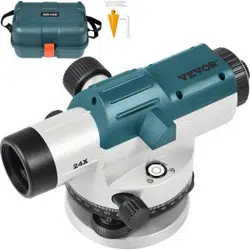
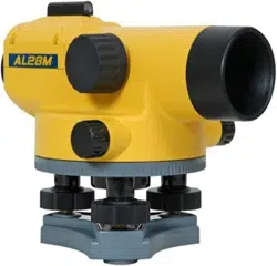
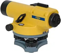
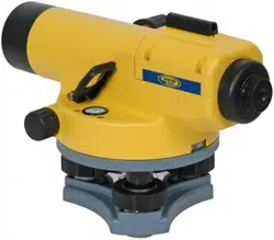
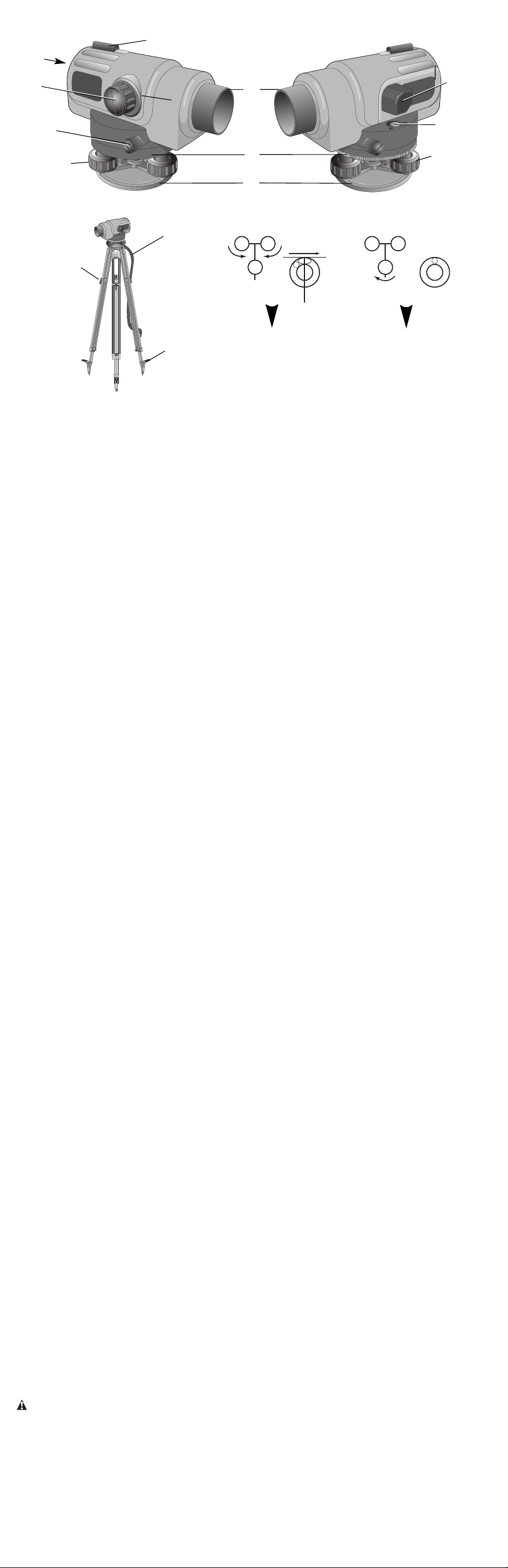
Components (Fig. 1, 2)
A. Base Plate F. Focusing Knob
B. Horizontal Circle G. Horizontal Tangent Drive
C. Eyepiece (not shown) H. Leveling Screws
D. Optical Peep Sight I. Bubble Viewing Prism
E. Objective Cover J. Circular Bubble
To ensure the accuracy of your instrument, check to make sure it is calibrated often. See the
Field Calibration Check section of this manual.
ASSEMBLY
The DW096 Automatic Level is fully assembled at the factory. No further assembly is nec-
essary. See the following instructions regarding the tripod.
Tripod Setup
1. Loosen the straps (K) around the tripod legs. Lift the extension quick-release clamps (L).
2. With the tripod closed, extend the legs so the tripod head is approximately eye level.
Tighten the quick-release clamps.
3. Position the legs in a triangular position. Fix the legs firmly into the ground by pressing
on the tripod shoes (M).
4. Gently remove the level from the carrying case. Note how the level is packed so that it
can be placed back in the same position.
5. Carefully position the instrument in the approximate center of the tripod head as shown
in Figure 3. Insert the tripod centering screw into the base plate, taking care to align the
threads properly. Tighten the screw until the instrument fits snug on the tripod. Do not over-
tighten or strip the threads.
6. Center the circular bubble (J) on the level by turning the leveling screws (H) as shown in
Figure 4.
OPERATION
Pointing and Focusing
1. Point the telescope towards a bright background or hold a white sheet of paper in front
of objective. Turn the eyepiece until the crosshairs are sharp and black.
2. Turn the level towards the staff by using the optical peep sight (D).
3. Looking through the eyepiece, turn the focusing knob (F) until the image of the staff is
sharp and clear.
4. Turn the horizontal tangent drive (G) to set the vertical hair down the center of the staff.
Measuring
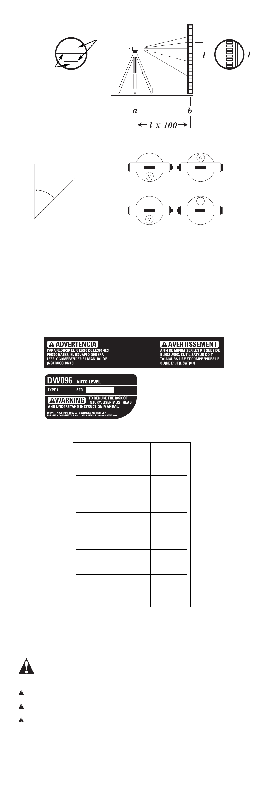
HEIGHT MEASUREMENT
Read the staff at the middle stadia line (Fig. 5).
STADIA MEASUREMENT
The Automatic Level is equipped with a stadia reticle so you can make simple distance
estimates. The stadia lines are located in the reticle (Figure 5). Sight the rod, read the two
observations at the stadia lines, take the difference of these observations and multiply by
100 to estimate the distance between the rod and the center of the instrument.
ANGLE MEASUREMENT
1. Sight point A with vertical hair and note the reading “a” on the horizontal circle (Fig. 6).
2. Turn the level to sight point B and note the reading “b”.
3. The angle is a – b.
Checking and Adjusting
CIRCULAR BUBBLE
1. Center the bubble (J) by using the leveling screws (H), then turn the instrument 180˚.
The bubble should remain centered (Fig. 7). If the bubble moves out of center, the
bubble needs adjustment (Fig. 8).
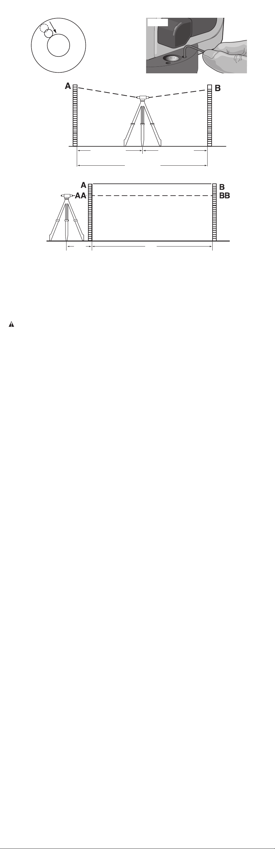
2. If the bubble needs adjustment, turn the leveling screws to bring the bubble halfway to
the center (Fig. 9). Using the Allen wrench provided, turn the two bubble adjustment
screws to center the bubble (Fig. 10).
3. Repeat the above procedure until the bubble remains centered when the instrument is
turned 180˚.
Field Calibration Check (Fig. 11, 12)
1. Place two rods facing each other at points A and B at a distance of 50 - 80m apart
(Fig. 11). Set up your instrument about halfway between A and B.
2. Sight the rods and take readings on point A as A and on point B as B.
3. Set the instrument at point D which is about 2m from point A (Fig. 12).
4. Sight the rods at point A, take reading as AA. Then, sight the rod at point B, take reading
as BB.
5. Use the following equation to calculate:
BB’ = AA – (A – B)
The instrument is in its perfect condition if BB’ = BB, otherwise, it needs adjustment.
MAINTENANCE
In order to protect all parts and not to lose its accuracy, care must be taken.
1. The instrument should always be kept properly encased when not in use, for maximum
protection.
2. Keep the instrument clean and free of dirt and moisture. After use, clean every part of the
instrument completely before putting it back in its case.
3. The interior parts are not user serviceable. Do not remove any lenses. Do not attempt to
clean, oil or repair interior parts.
4. After working in dusty locations, remove all dust from the lenses with a clean, soft tissue
or cloth and brush the leveling and tangent screws threads with a small brush.
5. When working near moving equipment, never leave your instrument unattended.
6. Make sure not to over tighten the leveling screw, clamp screw or adjusting screw.
7. Always spread the tripod legs to insure a stable setup. When setting up your tripod on an
incline, make sure two of the three legs are on the lower side of the incline. When setting
up on a pavement or other hard surface, try to protect the legs from slipping by either
making holes for the legs to sit in or blocking the legs.
8. It is recommended that a qualified service technician check the instrument periodically.
Accessories
Recommended accessories for use with your tool are available at extra cost from your local
dealer or authorized service center. If you need assistance in locating any accessory for your
tool, contact: D
EWALT Industrial Tool Co., 701 East Joppa Road, Baltimore, MD 21286.
CAUTION: The use of any other accessory not recommended for use with this tool could
be hazardous.
Repairs
To assure product SAFETY and RELIABILITY, repairs, maintenance and adjustment should
be performed by authorized service centers or other qualified service personnel, always
using identical replacement parts.
Full Warranty
DEWALT heavy duty industrial tools are warranted for one year from date of purchase. We
will repair, without charge, any defects due to faulty materials or workmanship. For warranty
INSTRUCTION MANUAL
GUIDE D'UTILISATION
MANUAL DE INSTRUCCIONES
DW096 Automatic Level
Niveau automatique DW096
DW096 Nivel automático
INSTRUCTIVO DE OPERACIÓN, CENTROS DE SERVICIO Y PÓLIZA
DE GARANTÍA. ADVERTENCIA: LÉASE ESTE INSTRUCTIVO
ANTES DE USAR EL PRODUCTO.
D
EWALT Industrial Tool Co., 701 East Joppa Road, Baltimore, MD 21286
(DEC03-CD-1) Form No. 621650-00 DW096 Copyright © 2003
Questions? See us in the World Wide Web at www.dewalt.com
The following are trademarks for one or more DEWALT power tools: the yellow and black
color scheme; the “D” shaped air intake grill; the array of pyramids on the handgrip; the kit
box configuration; and the array of lozenge-shaped humps on the surface of the tool.
FIG. 1
E
F
C
A
B
G
D
H
FIG. 2
J
I
H
FIG. 3
K
M
L
FIG. 4
FRONT
DEVANT
FRENTE
FRONT
DEVANT
FRENTE
IF YOU HAVE ANY QUESTIONS OR COMMENTS ABOUT THIS OR ANY DEWALT TOOL,
CALL US TOLL FREE AT: 1-800-4-D
EWALT (1-800-433-9258)
Safety Instructions for Levels
WARNING! Read and understand all instructions. Failure to follow all
instructions listed below may result in electric shock, fire and/or serious
personal injury.
SAVE THESE INSTRUCTIONS
DANGER: Do not operate during storms or near high voltage. NEVER attempt to use
a grade rod in a storm or near overhanging electric wires.
DANGER: Do not use optical tools such as a telescope or transit to view a laser
beam. Serious eye injury could result.
DANGER: Always be sure to set up optical instruments so that any user will not
intentionally or accidentally look through the instrument at the sun or any other
source of bright light, keeping in mind that the sun moves throughout the day.
• Store level out of reach of children and other untrained persons.
• Use only accessories that are recommended by the manufacturer for your model.
Accessories that may be suitable for one level, may create a risk of injury when used on
another level.
•Tool service must be performed only by qualified repair personnel. Service or
maintenance performed by unqualified personnel may result in injury. To locate your
nearest D
EWALT service center call 1-800-4-DEWALT (1-800-433-9258) or go to
http://www.dewalt.com on the Internet.
• Do not operate the level around children or allow children to operate the level.
Serious eye injury may result.
• Do not remove or deface warning labels.
• Position the level securely on a level surface. Damage to the level or serious injury
could result if the level falls.
WARNING: This product contains chemicals, including lead, known to the State of
California to cause cancer, and birth defects or other reproductive harm. Wash hands after
handling.
• Avoid prolonged contact with dust from power sanding, sawing, grinding, drilling,
and other construction activities. Wear protective clothing and wash exposed
areas with soap and water. Allowing dust to get into your mouth, eyes, or lay on the skin
may promote absorption of harmful chemicals.
Components (Fig. 1, 2)
A. Base Plate F. Focusing Knob
B. Horizontal Circle G. Horizontal Tangent Drive
C. Eyepiece (not shown) H. Leveling Screws
D. Optical Peep Sight I. Bubble Viewing Prism
E. Objective Cover J. Circular Bubble
To ensure the accuracy of your instrument, check to make sure it is calibrated often. See the
Field Calibration Check section of this manual.
ASSEMBLY
The DW096 Automatic Level is fully assembled at the factory. No further assembly is nec-
essary. See the following instructions regarding the tripod.
Tripod Setup
1. Loosen the straps (K) around the tripod legs. Lift the extension quick-release clamps (L).
2. With the tripod closed, extend the legs so the tripod head is approximately eye level.
Tighten the quick-release clamps.
3. Position the legs in a triangular position. Fix the legs firmly into the ground by pressing
on the tripod shoes (M).
4. Gently remove the level from the carrying case. Note how the level is packed so that it
can be placed back in the same position.
5. Carefully position the instrument in the approximate center of the tripod head as shown
in Figure 3. Insert the tripod centering screw into the base plate, taking care to align the
threads properly. Tighten the screw until the instrument fits snug on the tripod. Do not over-
tighten or strip the threads.
6. Center the circular bubble (J) on the level by turning the leveling screws (H) as shown in
Figure 4.
OPERATION
Pointing and Focusing
1. Point the telescope towards a bright background or hold a white sheet of paper in front
of objective. Turn the eyepiece until the crosshairs are sharp and black.
2. Turn the level towards the staff by using the optical peep sight (D).
3. Looking through the eyepiece, turn the focusing knob (F) until the image of the staff is
sharp and clear.
4. Turn the horizontal tangent drive (G) to set the vertical hair down the center of the staff.
Measuring
HEIGHT MEASUREMENT
Read the staff at the middle stadia line (Fig. 5).
STADIA MEASUREMENT
The Automatic Level is equipped with a stadia reticle so you can make simple distance
estimates. The stadia lines are located in the reticle (Figure 5). Sight the rod, read the two
observations at the stadia lines, take the difference of these observations and multiply by
100 to estimate the distance between the rod and the center of the instrument.
ANGLE MEASUREMENT
1. Sight point A with vertical hair and note the reading “a” on the horizontal circle (Fig. 6).
2. Turn the level to sight point B and note the reading “b”.
3. The angle is a – b.
Checking and Adjusting
CIRCULAR BUBBLE
1. Center the bubble (J) by using the leveling screws (H), then turn the instrument 180˚.
The bubble should remain centered (Fig. 7). If the bubble moves out of center, the
bubble needs adjustment (Fig. 8).
2. If the bubble needs adjustment, turn the leveling screws to bring the bubble halfway to
the center (Fig. 9). Using the Allen wrench provided, turn the two bubble adjustment
screws to center the bubble (Fig. 10).
3. Repeat the above procedure until the bubble remains centered when the instrument is
turned 180˚.
Field Calibration Check (Fig. 11, 12)
1. Place two rods facing each other at points A and B at a distance of 50 - 80m apart
(Fig. 11). Set up your instrument about halfway between A and B.
2. Sight the rods and take readings on point A as A and on point B as B.
3. Set the instrument at point D which is about 2m from point A (Fig. 12).
4. Sight the rods at point A, take reading as AA. Then, sight the rod at point B, take reading
as BB.
5. Use the following equation to calculate:
BB’ = AA – (A – B)
The instrument is in its perfect condition if BB’ = BB, otherwise, it needs adjustment.
MAINTENANCE
In order to protect all parts and not to lose its accuracy, care must be taken.
1. The instrument should always be kept properly encased when not in use, for maximum
protection.
2. Keep the instrument clean and free of dirt and moisture. After use, clean every part of the
instrument completely before putting it back in its case.
3. The interior parts are not user serviceable. Do not remove any lenses. Do not attempt to
clean, oil or repair interior parts.
4. After working in dusty locations, remove all dust from the lenses with a clean, soft tissue
or cloth and brush the leveling and tangent screws threads with a small brush.
5. When working near moving equipment, never leave your instrument unattended.
6. Make sure not to over tighten the leveling screw, clamp screw or adjusting screw.
7. Always spread the tripod legs to insure a stable setup. When setting up your tripod on an
incline, make sure two of the three legs are on the lower side of the incline. When setting
up on a pavement or other hard surface, try to protect the legs from slipping by either
making holes for the legs to sit in or blocking the legs.
8. It is recommended that a qualified service technician check the instrument periodically.
Accessories
Recommended accessories for use with your tool are available at extra cost from your local
dealer or authorized service center. If you need assistance in locating any accessory for your
tool, contact: D
EWALT Industrial Tool Co., 701 East Joppa Road, Baltimore, MD 21286.
CAUTION: The use of any other accessory not recommended for use with this tool could
be hazardous.
Repairs
To assure product SAFETY and RELIABILITY, repairs, maintenance and adjustment should
be performed by authorized service centers or other qualified service personnel, always
using identical replacement parts.
Full Warranty
DEWALT heavy duty industrial tools are warranted for one year from date of purchase. We
will repair, without charge, any defects due to faulty materials or workmanship. For warranty
INSTRUCTION MANUAL
GUIDE D'UTILISATION
MANUAL DE INSTRUCCIONES
DW096 Automatic Level
Niveau automatique DW096
DW096 Nivel automático
INSTRUCTIVO DE OPERACIÓN, CENTROS DE SERVICIO Y PÓLIZA
DE GARANTÍA. ADVERTENCIA: LÉASE ESTE INSTRUCTIVO
ANTES DE USAR EL PRODUCTO.
D
EWALT Industrial Tool Co., 701 East Joppa Road, Baltimore, MD 21286
(DEC03-CD-1) Form No. 621650-00 DW096 Copyright © 2003
Questions? See us in the World Wide Web at www.dewalt.com
The following are trademarks for one or more DEWALT power tools: the yellow and black
color scheme; the “D” shaped air intake grill; the array of pyramids on the handgrip; the kit
box configuration; and the array of lozenge-shaped humps on the surface of the tool.
FIG. 1
E
F
C
A
B
G
D
H
FIG. 2
J
I
H
FIG. 3
K
M
L
FIG. 4
FRONT
DEVANT
FRENTE
FRONT
DEVANT
FRENTE
repair information, call 1-800-4-DEWALT. This warranty does not apply to accessories or
damage caused where repairs have been made or attempted by others. This warranty gives
you specific legal rights and you may have other rights which vary in certain states or
provinces.
In addition to the warranty, D
EWALT tools are covered by our:
30 DAY NO RISK SATISFACTION GUARANTEE
If you are not completely satisfied with the performance of your D
EWALT heavy duty indus-
trial tool, simply return it to the participating seller within 30 days for a full refund. Please
return the complete unit, transportation prepaid. Proof of purchase may be required.
FREE WARNING LABEL REPLACEMENT: If your warning labels become illegible or are
missing, call 1-800-4-D
EWALT for a free replacement.
Item/Model 26x
Standard deviation
for 1km double 1.5mm
run leveling
Image Erect
Magnification 26x
Objective aperture 38mm
Field of view 1˚20'
Minimum focus 0.5m
Multiplication constant 100
Additive constant 0
Compensator range ±15'
Compensator setting ±0.5"
accuracy
Sensitivity of bubble 8'/2mm
Horizontal circle - accuracy 1˚
Instrument net weight 1.85kg
Tripod M16 or 5/8"
D
FIG. 12
1/2 (L) 1/2 (L)
L= 50 - 80m
FIG. 11
L
L
2m
FIG. 9
FIG. 10
FIG. 7
FIG. 8
FIG. 5
CROSSHAIRS
FILS CROISÉS
HILOS DE
CRUZ FILAR
STADIA LINES
TRAITS STADIMÉTRIQUES
LÍNEAS ESTADIMÉTRICAS
FIG. 6
b
O
a
Ø
A
B
SI VOUS AVEZ DES QUESTIONS OU VOUS VOULEZ NOUS FAIRE PART DE VOS
COMMENTAIRES CONCERNANT CET OUTIL OU TOUT AUTRE OUTIL D
EWALT,
COMPOSEZ SANS FRAIS LE : 1 800 4-DEWALT (1 800 433-9258)
Consignes de sécurité concernant les niveaux
AVERTISSEMENT ! Lire, comprendre et suivre toutes les directives
précisées ci-dessous, y compris les consignes de sécurité, afin d’éviter
les risques de choc électrique, d’incendie ou de blessure grave.
CONSERVER CES DIRECTIVES
DANGER : Ne pas utiliser pendant un orage ni près de lignes à haute tension. NE
JAMAIS utiliser le tube jaugeur pendant un orage ni près de fils électriques suspendus.
DANGER : Ne pas utiliser un dispositif optique, tel qu’un télescope ou un théodo-
lite, pour examiner le faisceau laser afin d’éviter de blesser grièvement les yeux.
DANGER : Toujours s’assurer d’installer les instruments optiques de manière à
empêcher l’utilisateur de regarder, volontairement ou accidentellement, le soleil ou
toute autre source de lumière intense à travers ceux-ci, étant donné que le soleil se
déplace toute la journée.
• Ranger le niveau hors de la portée des enfants ou des personnes non qualifiées.
•N’utiliser que les accessoires recommandés par le fabricant pour le modèle
concerné; un accessoire destiné à un niveau particulier peut devenir dangereux lorsqu’il
est utilisé avec un autre.
•L’outil ne doit être réparé ou entretenu par le personnel qualifié seulement; toute
maintenance effectuée par une personne non qualifiée pourrait entraîner des
risques de blessure. Pour obtenir le numéro du centre de service DEWALT le plus près,
composer le 1 800 433-9258 ou consulter le site Internet http://www.dewalt.com.
• Ne pas utiliser le niveau et en présence d’un enfant, ni autoriser les enfants à
utiliser ces instruments afin d’éviter les blessures graves aux yeux.
• Ne pas retirer ni abîmer les étiquettes d’avertissement.
• S’assurer de bien déposer le niveau sur une surface de niveau afin de l’empêcher de
tomber et de s’endommager ou de blesser l’utilisateur.
AVERTISSEMENT : Ce produit contient des produits chimiques, y compris le plomb, qui,
dans l’État de la Californie, sont reconnus comme étant susceptibles de causer le cancer,
d’entraîner des malformations congénitales ou d’être nocifs pour le système reproductif.
Se laver les mains après chaque utilisation.
• Éviter tout contact prolongé avec la poussière soulevée par cet outil ou autres
outils électriques. Porter des vêtements de protection et nettoyer les parties
exposées du corps à l’eau savonneuse. S’assurer de bien se protéger afin d’éviter
d’absorber par la bouche, les yeux ou la peau des produits chimiques nocifs.
Composants (Fig. 1 et 2)
A. Plaque de fixation F. Bouton de mise au point
B. Cercle horizontal G. Entraînement tangentiel horizontal
C. Oculaire (non illustré) H. Vis de mise de niveau
D. Lunette de visée optique I. Prisme de visée de la bulle
E. Couvercle de l’objectif J. Bulle circulaire
Vérifier fréquemment l’étalonnage de l’instrument afin d’en assurer la précision. Pour ce faire,
consulter la section « Vérification de l’étalonnage sur place » du présent guide.
ASSEMBLAGE
Le niveau automatique DW096 est complètement assemblé en usine; aucun montage
complémentaire n’est requis. Voir les directives suivantes concernant le trépied.
Installation du trépied
1. Desserrer la courroie (K) enroulée autour des pattes du trépied, puis soulever les brides
à décrochage rapide de la rallonge (L).
2. Fermer le trépied, puis sortir les pattes de manière à placer la tête du trépied à peu près
à la hauteur des yeux; serrer les brides à décrochage rapide.
3. Positionner les pattes de manière à former un triangle, puis les fixer solidement au sol en
appuyant sur les semelles du trépied (M).
4. Retirer doucement le niveau de la mallette de transport, en notant la position dans
laquelle il a été emballé afin de le remettre dans la même position.
5. Placer délicatement l’instrument à peu près au centre de la tête du trépied, tel qu’illustré
à la figure 3, puis insérer la vis de centrage du trépied dans la plaque de fixation, en
prenant soin d’aligner les filets correctement. Serrer la vis afin de bien fixer l’instrument
sur le trépied; ne pas trop serrer ni fausser le pas de vis.
6. Centrer la bulle circulaire (J) dans le niveau en tournant les vis de mise de niveau (H)
selon l’illustration à la figure 4.
FONCTIONNEMENT
Pointé et mise au point
1. Pointer le télescope vers un arrière-plan clair ou tenir une feuille de papier blanche
devant l’objectif, puis tourner l’oculaire jusqu’à ce que les fils croisés soient bien définis
et noirs.
2. Tourner le niveau vers le bâton d’équerre au moyen de la lunette de visée optique (D).
3. Regarder dans l’oculaire et tourner le bouton de mise au point (F) jusqu’à ce que l’image
du bâton d’équerre soit claire et bien définie.
4. Tourner l’entraînement tangentiel horizontal (G) afin de régler le fil vertical au centre du
bâton d’équerre.
Mesures
MESURE DE LA HAUTEUR
Lire le bâton d’équerre, sur le fil stadimétrique central (fig. 5).
MESURE STADIMÉTRIQUE
Le niveau automatique est doté d’un stadia avec réticule permettant de mesurer facilement
les distances. Les traits stadimétriques sont situés dans le réticule (figure 5). Pour estimer la
distance entre la mire et le centre de l’instrument, viser la mire, lire les deux indications des
traits, calculer la différence entre ces deux indications et multiplier par 100.
MESURE D’ANGLE
1. Viser le point A avec le fil vertical et noter la lecture « a » sur le cercle horizontal (fig. 6).
2. Tourner le niveau et viser le point B, puis noter la lecture « b ».
3. L’angle est a – b.
Vérification et réglage
BULLE CIRCULAIRE
1. Centrer la bulle (J) au moyen des vis de mise de niveau (H), puis tourner l’instrument de
180 °; la bulle devrait rester centrée (fig. 7). Si la bulle se déplace, on doit la régler afin
de la centrer de nouveau (fig. 8).
2. Pour régler la bulle, tourner les vis de mise de niveau de manière à ramener la bulle au
centre (fig. 9). Au moyen de la clé Allen fournie, tourner les deux vis de réglage de la bulle
afin de la centrer (fig. 10).
3. Reprendre les étapes décrites ci-dessus jusqu’à ce que la bulle reste centrée lorsqu’on
tourne l’instrument de 180 °.

Vérification de l’étalonnage sur place (Fig. 11 et 12)
1. Placer deux mires une en face de l’autre aux points A et B, à une distance de 50 à 80
mètres une par rapport à l’autre (fig. 11). Installer l’instrument environ à mi-chemin entre
les points A et B.
2. Viser les mires et effectuer la lecture au point A (comme étant A) et au point B (comme
étant B).
3. Installer l’instrument au point D, à environ 2 mètres du point A (fig. 12).
4. Viser les mires au point A et prendre la lecture (comme étant AA), puis viser la mire au
point B et prendre la lecture (comme étant BB).
5. Utiliser l’équation suivante pour calculer :
BB’ = AA – (A – B)
L’instrument est parfaitement étalonné lorsque BB’ = BB; sinon, on doit le régler de
nouveau.
ENTRETIEN
Afin de protéger les pièces de l’instrument et d’assurer la précision de ce dernier, on doit
s’assurer de l’entretenir correctement
1. L’instrument doit toujours être rangé dans sa mallette après chaque utilisation afin de le
protéger le mieux possible.
2. Garder l’instrument propre et exempt de poussière et d’humidité. Après chaque
utilisation, nettoyer à fond chaque partie de l’instrument avant de remettre ce dernier
dans la mallette.
3. L’outil ne comprend aucune pièce interne destinée à être entretenue par l’utilisateur. Ne
pas enlever les lentilles, ni tenter de nettoyer, de graisser ou de réparer les pièces
internes
4. Après avoir travaillé dans un endroit poussiéreux, enlever toute trace de poussière
accumulée sur les lentilles au moyen d’un linge ou d’un tissu propre et doux; utiliser une
petite brosse pour brosser les filets des vis de mise de niveau et des vis tangentes.
5. Ne jamais laisser l’instrument sans surveillance lorsqu’on travaille près d’un équipement
en mouvement.
6. Éviter de trop serrer la vis de mise de niveau, la vis de la bride ou la vis de réglage.
7. Toujours étendre les pattes du trépied afin d’assurer sa stabilité. Lorsqu’on l’installe sur
une pente, s’assurer de placer deux des trois pattes sur la partie inférieure de la pente;
sur la chaussée ou sur une surface dure, on doit empêcher les pattes de glisser en les
enfonçant dans des trous ou en les bloquant.
8. On recommande de faire vérifier périodiquement l’instrument par un technicien de
service qualifié.
Accessoires
Les accessoires recommandés pour cet outil sont vendus séparément chez les dépositaires
locaux ou dans les centres de service autorisés. Pour obtenir plus d’information sur les
accessoires, communiquer avec : D
EWALT Industrial Tool Co., 701 East Joppa Road,
Baltimore, MD 21286, aux États-Unis.
MISE EN GARDE : L’usage d’un accessoire non recommandé pourrait présenter un
danger.
Réparations
Pour assurer la SÉCURITÉ et la FIABILITÉ de ce produit, toutes les opérations de répara-
tion, d’entretien et de réglage doivent être effectuées dans un centre de service autorisé ou
par du personnel qualifié; on ne doit utiliser que des pièces de rechange identiques.
Garantie compléte
DE
WALT garantit les outils industriels de service intensif contre tout défaut de matériel ou de
fabrication pour une période d’un an à compter de la date d’achat; le produit défectueux sera
réparé sans frais. Pour obtenir de plus amples renseignements sur les réparations couvertes
par la présente garantie, composer le 1 800 4-D
E
WALT (1 800 433-9258). Cette garantie ne
s’applique pas aux accessoires et ne vise pas les dommages causés par des réparations
effectuées par un tiers. Cette garantie confère des droits légaux particuliers à l’acheteur, mais
celui-ci pourrait aussi bénéficier d’autres droits variant d’un territoire à l’autre. En plus de la
présente garantie, la
GARANTIE SANS RISQUE DE 30 JOURS EN CAS DE NON-SATISFACTION
s’applique également aux outils D
EWALT.
Si l’acheteur n’est pas entièrement satisfait du rendement de l’outil industriel de service
intensif D
EWALT, celui-ci peut le retourner au vendeur participant dans les 30 jours pour
obtenir un remboursement intégral. Retourner l’outil au complet en payant le transport à
l’avance; une preuve d’achat peut être requise.
REMPLACEMENT GRATUIT DE L’ÉTIQUETTE D’AVERTISSEMENT : En cas de perte ou
d’endommagement des étiquettes d’endommagement, composer le 1 800 4-D
EWALT
(1 800 433-9258) afin d’en obtenir de nouvelles sans frais.
Item/Model 26x
Écart type pour un
double nivellement 1,5mm
de 1 km
Image Droite
Grossissement 26x
Ouverture de l’objectif 38mm
Champ de vision 1˚20'
Mise au point minimale 0,5m
Facteur de multiplication 100
Constante additionnelle 0
Gamme du compensateur ±15'
Précision de réglage ±0,5"
du compensateur
Sensibilité de la bulle d’air 8'/2mm
Cercle horizontal - Précision 1˚
Poids net de l’instrument 1,85 kg
Trépied M16 ou 5/8po
Instrucciones de seguridad para niveles
¡ADVERTENCIA! Lea todas las instrucciones hasta comprenderlas. No
ajustarse a las instrucciones siguientes puede ser causa de choque eléctrico,
incendio o lesiones graves.
GUARDE ESTAS INSTRUCCIONES
PELIGRO: No utilizar durante una tempestad o cerca de alto voltaje. NUNCA trate
de utilizar una regla graduada cerca de cables eléctricos suspendidos encima.
PELIGRO: No utilice herramientas ópticas tales como un telescopio o tránsito para
mirar un rayo láser. Puede resultar en lesión ocular grave
PELIGRO: Asegúrese siempre de montar los instrumentos ópticos de tal manera
que un usuario no pueda mirar al sol u otra fuente de luz luminosa, ya sea intencional
o en forma accidental, tomando en cuenta que el sol se traslada a lo largo del día.
•Guarde el nivel fuera del alcance de los niños y otras personas no capacitadas.
•
Utilice únicamente los accesorios que el fabricante recomienda para su
modelo. Un mismo accesorio puede ser adecuado para un nivel pero peligroso si se usa
en otro nivel.
•
El servicio a la herramienta sólo debe realizarlo personal calificado. El
servicio o mantenimiento realizados por personal no calificado puede
ocasionar lesiones. Para localizar a su centro de servicio DE
WALT más cercano llame
al 1-800-DEWALT (1-800-433-9258) o vaya al portal http://www.dewalt.com en la Internet.
• No trabaje con el nivel si hay niños alrededor, ni deje que éstos manejen el nivel.
Puede ser muy perjudicial para los ojos.
•
No retire ni tache las etiquetas de advertencia.
• Poscione el nivel firmemente sobre una superficie plana. De caerse el nivel, esto
podría dañar al nivel y lesiones graves.
ADVERTENCIA: Este producto contiene sustancias químicas, incluyendo plomo, que en
el Estado de California se consideran causantes de cáncer, defectos congénitos y otros
daños reproductivos. Lávese las manos después de manipularlo.
• Evite el contacto prolongado con el polvo proveniente del lijado, aserrado, amolado
y taladrado eléctrico, así como otras actividades de construcción. Use vestimenta
protectora y lave las áreas expuestas con agua y jabón. Si el polvo penetra en su boca,
ojos o si permanece sobre su piel podría promover la absorción de químicos dañinos.
Componentes (Fig. 1, 2)
A. Placa de base G. Dispositivo de accionamiento
B. Círculo horizontal para tangente horizontal
C. Pieza ocular (sin mostrar) H. Tornillos lniveladores
D. Mirilla óptica I. Prisma de observación de la burbuja
E. Cubierta del objetivo J. Burbuja circular
F. Perilla de enfoque
Para asegurar la exactitud de este instrumento, verifique su calibración frecuentemente para
asegurarse de su correcta calibración. Vea la sección Verificación de calibración de
campo de este manual.
ENSAMBLADO
El nivel automático DW096 viene completamente ensamblado de fábrica. No hay necesidad
de ensamblar nada. Vea las instrucciones siguientes relativos al montaje del trípode.
Montaje del trípode
1. Afloje las tiras (K) alrededor de las patas del trípode. Levante las abrazaderas de
extensión de liberación rápida (L).
2. Con el trípode cerrado, extienda las patas hasta que la cabeza del trípode se encuentre
a nivel de los ojos aproximadamente. Apriete las abrazaderas de liberación rápida.
3. Posicione las patas en posición triangular. Fije las patas firmemente en el suelo
presionando para esto los zapatos del trípode (M).
4. Extraiga cuidadosamente el nivel del estuche. Tome nota de cómo el nivel ha sido
empacado para poder colocarlo de vuelta en la misma posición.
5. Posicione el instrumento cuidadosamente en el centro aproximado de la cabeza de
trípode como lo ilustra la Figura 3. Inserte el tornillo de centrar del trípode en la placa de
base, poniendo atención en alinear las roscas adecuadamente. Apriete el tornillo hasta
que el instrumento quede bien encajado sobre el trípode. No apriete demasiado ni se
pase de la rosca.
6. Centre la burbuja circular (J) del el nivel girando los tornillos niveladores (H) como lo
ilustra la Figura 4.
OPERACIÓN
Orientar y enfocar
1. Oriente el telescopio hacia un fondo iluminado o mantenga una hoja de papel blanco
en frente del objetivo. Gire la pieza ocular hasta que los hilos de cruz filar se vuelvan
marcados y negros.
2. Gire el nivel hacia la escuadra de agrimensor utilizando la mirilla óptica (D).
3. Mirando a través de la pieza ocular, gire la perilla de enfoque (F) hasta obtener una
imagen marcada y clara de la escuadra de agrimensor.
4. Gire el dispositivo de accionamiento del tangente horizontal (G) para fijar el hilo vertical
en el centro de la escuadra.
Medición
MEDICIÓN DE ALTURA
Tome la lectura de la escuadra de agrimensor en la mitad de la línea estadimétrica (Fig. 5).
Medición estadimétrica
El nivel automático viene equipado con retículos estadimétricos para poder hacer estimados
de distancia sencillos. Las líneas estadimétricas están ubicadas en el retículo (Figura 5).
Vise la regla graduada, lea las dos observaciones en las líneas estadimétricas, tome la
diferencia de estas observaciones y multiplíquela por 100 para estimar la distancia entre la
regla graduada y el centro del instrumento.
MEDICIÓN ANGULAR
1. Vise el punto A con con hilo vertical y tome nota de la lectura “a” en el círculo horizontal
(Fig. 6).
2. Gire el nivel para visar el punto B y tome nota de la lectura “b”.
3. El ángulo es a – b.
Verificación y ajuste
BURBUJA CIRCULAR
1. Centrar la burbuja (J) con los tornillos niveladores (H), luego gire el instrumento 180˚. La
burbuja debe permanecer centrada (Fig. 7). Si la burbuja se mueve fuera del centro,
necesita ajuste (Fig. 8).
2. Si la burbuja necesita ajuste, gire los tornillos niveladores para traer la burbuja a medio
camino del centro (Fig. 9). Con la llave Allen suministrada, gire los dos tornillos de ajuste
de burbuja para centrar la burbuja (Fig. 10).
3. Repita el procedimiento descrito hasta que la burbuja permanezca centrada cuando el
instrumento se gira 180˚.
Verificación de calibración de campo (Fig. 11, 12)
1. Coloque dos reglas graduadas una frente a la otra en los puntos A y B a una distancia de
50 - 80m la una de la otra (Fig. 11). Monte su instrumento a medio camino entre A y B.
2. Vise las reglas y tome las lecturas en el punto A como A y en el punto B como B.
3. Monte el instrumento en el punto D que está a alrededor de 2m del punto A (Fig. 12).
4. Vise las reglas del punto A, tome la lectura como AA. Luego vise la regla en el punto B,
tome la lectura como BB.
5. Use la siguiente ecuación para calcular:
BB’ = AA – (A – B)
El instrumento está en perfectas condiciones si BB’ = BB, de lo contrario necesita ajuste.
MANTENIMIENTO
Para que ninguna de las piezas pierdan su precisión, se debe poner cuidado en lo siguiente.
1. El instrumento debería mantenerse siempre bien guardado en su estuche cuando no se
utiliza, para su máxima protección.
2. Mantenga el instrumento limpio y libre de impurezas y humedad. Limpie cada parte del
instrumento completamente después de haberlo usado, antes de guardarlo en su
estuche.
3. El usuario no puede reparar las partes internas. No quite ninguno de los lentes. No trate
de limpiar, aceitar o reparar las partes internas.
4. Después de trabajar en sitios de mucho polvo, quite el polvo de los lentes con un papel
o trapo suave y limpio y cepille las roscas de lo tornillos de nivelado y tangente con un
cepillo pequeño.
5. Cuando trabaje cerca de un equipo en movimiento, nunca deje su instrumento sin
supervisión.
6. Asegúrese de no apretar demasiado los tornillos de nivelado, de abrazadera o de ajuste.
7. Despliegue siempre las patas del trípode para asegurar un montaje estable. Al montar
su trípode sobre una pendiente, asegúrese de que dos de las tres patas se ubiquen
sobre el lado más bajo de la pendiente. Al montarlo sobre el pavimento u otra superficie
dura, trate de proteger las patas contra el resbalamiento haciendo huecos para asentar
las patas o bloqueándolas.
8. Se recomienda que los instrumentos sean examinados periódicamente por un técnico
de servicio competente.
Accesorios
Los accesorios recomendados para su herramienta están disponibles con un cargo adicional
en su distribuidor local o en el centro de servicio autorizado. Si usted necesita ayuda para
encontrar un accesorio para su herramienta, contacte a: D
EWALT Industrial Tool Co., 701
East Joppa Road, Baltimore, MD 21286.
PRECAUCIÓN: La utilización de cualquier accesorio no recomendado para esta
herramienta puede ser peligrosa.
Reparaciones
Para garantizar la SEGURIDAD y la CONFIABILIDAD, deberán hacerse reparaciones,
mantenimiento y ajustes de esta herramienta en los centros autorizados de servicio D
EWALT
u otras organizaciones autorizadas. Estas organizaciones prestan servicio a las herramientas
D
EWALT y emplean siempre refacciones legitimas DEWALT.
Póliza de Garantía
IDENTIFICACIÓN DEL PRODUCTO:
Sello o firma del Distribuidor.
Nombre del producto: ______________________ Mod./Cat.: ______________________
Marca: ________________________________ Núm. de serie:_____________________
(Datos para ser llenados por el distribuidor)
Fecha de compra y/o entrega del producto: _____________________________________
Nombre y domicilio del distribuidor donde se adquirió el producto:
________________________________________________________________________
Este producto está garantizado por un año a partir de la fecha de entrega, contra cualquier
defecto en su funcionamiento, así como en materiales y mano de obra empleados para su
fabricación. Nuestra garantía incluye la reparación o reposición del producto y/o compo-
nentes sin cargo alguno para el cliente, incluyendo mano de obra, así como los gastos de
transportación razonablemente erogados derivados del cumplimiento de este certificado.
Para hacer efectiva esta garantía deberá presentar su herramienta y esta póliza sellada
por el establecimiento comercial donde se adquirió el producto, de no contar con ésta, bas-
tará la factura de compra.
EXCEPCIONES.
Esta garantía no será válida en los siguientes casos:
• Cuando el producto se hubiese utilizado en condiciones distintas a las normales;
• Cuando el producto no hubiese sido operado de acuerdo con el instructivo de uso que
se acompaña;
• Cuando el producto hubiese sido alterado o reparado por personas distintas a las
enlistadas al final de este certificado.
Anexo encontrará una relación de sucursales de servicio de fábrica, centros de servicio
autorizados y franquiciados en la República Mexicana, donde podrá hacer efectiva su garan-
tía y adquirir partes, refacciones y accesorios originales.
Garantía Completa
Las herramientas industriales DEWALT están garantizadas durante un año a partir de la
fecha de compra. Repararemos, sin cargos, cualquier falla debida a material o mano de
obra defectuosos. Por favor regrese la unidad completa, con el transporte pagado, a
cualquier Centro de Servicio para Herramientas Industriales de D
EWALT o a las estaciones
de servicio autorizado enlistadas bajo “Herramientas Eléctricas” en la Sección Amarilla.
Esta garantía no se aplica a los accesorios ni a daños causados por reparaciones
efectuadas por terceras personas. Esta garantía le otorga derechos legales específicos, y
usted puede tener otros derechos que pueden variar de estado a estado.
En adición a la garantía, las herramientas D
EWALT están amparadas por nuestra:
GARANTÍA DE SATISFACCIÓN SIN RIESGO POR 30 DÍAS
Si usted no se encuentra completamente satisfecho con el desempeño de su herramienta
industrial D
EWALT, sencillamente devuélvala a los vendedores participantes durante los
primeros 30 días después de la fecha de compra para que le efectúen un reembolso
completo. Por favor regrese la unidad completa, con el transporte pagado. Se puede requerir
prueba de compra.
SUSTITUCIÓN GRATUITA DE LAS ETIQUETAS DE ADVERTENCIA: Si las etiquetas de
advertencia se vuelven ilegibles o se pierden, llame al 1-800-4-D
EWALT para conseguir
gratuitamente otras de repuesto.
PARA REPARACIÓN Y SERVICIO DE SUS HERRAMIENTAS ELÉCTRICAS DIRÍJASE
AL CENTRO DE SERVICIO MÁS CERCANO
AGUASCALIENTES
Av. de los Maestros 903 - Col. España 449-913-38-01
CAMPECHE
Av. Gobernadores 345 - Col. Santa Ana 981-811-34-90
CHIAPAS
5 Norte Oriente 460 - Col. Centro 961-600-02-87
CHIHUAHUA
Av. Universidad 2903 - Col. Universidad 614-413-64-04
DURANGO
Av. 20 de Noviembre 2004 Ote - Col. Centro 618-818-80-77
GUANAJUATO
1 Mayo 482 - Col. Centro 462-626-79-22
GUADALAJARA
Av. Vallarta 4901-a - Col. Prados Vallarta 333-673-28-15
MÉXICO
16 de Septiembre 509 - Col. Alce Blanco 55-358-40-07
OAXACA
Av. Hidalgo 1303 - Col. Centro 951-514-46-12
SINALOA
Blvd. Manuel J. Clouther 3027
Col. Lomas del Blvd. 667-717-89-99
SAN LUIS POTOSÍ
Av. Universidad 1525 - Col. San Luis 444-814-23-83
SONORA
Nayarit 217 - Col. San Benito 662-210-25-50
TABASCO
Periférico 2047 - Col. Periférico 993-350-38-72
TAMAULIPAS
Tiburcio Garza Zamora 1185 - Col. Beatty 813-374-24-16
YUCATÁN
Calle 63 No. 459 - Col. Centro 999-923-08-49
TAMPICO
Av. Hidalgo 1801 - Col. Aurora 833-213-42-61
PARA OTRAS LOCALIDADES LLAME AL: 326 7100
Item/Model 26x
Desviación estándar en 1.5mm
1km doble nivelación
Imagen Erecto
Ampliación 26x
Abertura del objetivo 38mm
Campo de visión 1˚20'
Enfoque mínimo 0.5m
Constante de multiplicación 100
Constante aditiva 0
Límite compensador ±15'
Compensador de precisión ±0.5"
de fijación
Sensibilidad de la burbuja 8'/2mm
Círculo horizontal - exactitud 1˚
Peso neto del instrumento 1.85kg
Trípode M16 ó 5/8 pulg.
IMPORTADOR: DEWALT S.A. DE C.V.
BOSQUES DE CIDROS ACCESO RADIATAS NO. 42
COL. BOSQUES DE LAS LOMAS, 3A. SECCIÓN, CP 05120
DELEGACIÓN CUAJIMALPA, MÉXICO, D.F
TEL. 5 326 7100
R.F.C.: BDE810626-1W7
Para servicio y ventas consulte
“HERRAMIENTAS ELECTRICAS”
en la sección amarilla.