DAL 32H
D
AL
32N
D
AL 32P
ࠡ㿔
ᛳ䇶ᙼ䌁фᴀ݀ৌ⫳ѻⱘ㞾ࡼᅝᑇ∈ޚҾЎњܙߚথҾ఼ⱘᗻ㛑ˈ
䇋ᙼҨ㒚䯙䇏ᴀݠᑊཹֱㅵˈҹ᮹ৢখ㗗DŽ
⊼ᛣџ乍˖
᪡Ҿ఼Пࠡ㒣䖛䭓ᯊ䯈ⱘ䖤䕧Пৢˈ䛑ᖙ乏Ẕᶹ⌟䞣Ҿ఼ⱘᡒᑇ
㊒ᑺᰒ⼎㊒ᑺDŽ
ϡৃҹ䅽⇨⏫ܹҾ఼Ёˈгϡৃҹ䅽䰇ܝⳈ✻ᇘҾ఼ϞDŽ
Ҿ఼ϡৃҹ䭓ᳳᬒ㕂≑䔺ЁDŽ
㢹Ҿ఼Ꮉ໘ⱘ⏽ᑺϢᄬᬒ໘ⱘ⏽ᑺᏂᓖˈᑨܜᇚҾ఼⬭ㆅݙˈ
Ⳉ㟇ᅗ䗖ᑨ⦃๗⏽ᑺৢݡՓ⫼DŽ
Ҿ఼ϡৃҹᲱ䴆ᵕッⱘ⇨ϟˈӮᕅડҾ఼ⱘ⌟䞣ޚ⹂ᑺDŽ
ᑨ䙓ܡӏԩކᩲ䅽⌟䞣Ҿ఼ᥝ㨑ഄ䴶ϞDŽ
䭓䗨䖤䕧Ҿ఼ᯊˈᖙ乏ᡞҾ఼ᬒ㕂Ҿ఼ㆅݙDŽ䖤䕧ᯊᑨᇣᖗ䙓ܡ
ǃ⺄ᩲ࠻⚜䳛ࡼDŽ
ᴀҾ఼া㛑Ѹ㒭ড়ḐⱘϧϮҎׂ⧚ˈ㗠Ϩা㛑Փ⫼ⱘӊDŽ䴲
ϧϮҎϡৃ᪙㞾ᢚᓔҾ఼ˈҹܡথ⫳ϡᖙ㽕ⱘᤳണDŽ

ⴤᖋ
ၭܖၵ
1.1 DAL20-32ሗೖૌDAL20-32Nሗೖၭܖၵ
1.2 DAL20-32PሗೖૌDAL20-32Hሗೖၭܖၵ
ፏঋ܇ଚළݰ
ፏေᎭ
3.1 ፏضᓓ
3.2 ඳᔮᏕࡥଷ
4.1 ܪܶ
ܪজจ
4.2 ܪீಏ
4.3 ࢘ܪ
5.1 ႈଈܱ
5.2 ႈቧᒫ
5.3 iଈܱ
ፏ࠲ଈܱᏕࡥᒩ
ፏ࠲ᆬᏕډጞ
ᔢቆࠓ
5.4 iቧᒫ
1
1
2
3
4
4
4
5
5
6
6
7
7
7
7
9
9
9
1.1 DAL20-32 DAL20-32N
1
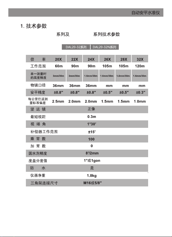
36 36 36
1.2 DAL20-32P DAL20-32H
2
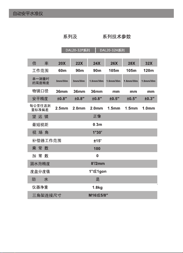
40 40 40
สᓗ
ᓖⴈ
ᓖⴈᤷ⽪⡼
㺕گಘ䬱
䈳❖䖞
ݹᆖⶴ߶ಘ
⢙䮌
≤ᒣᗚ⧟ᗞࣘ䖞
㝊㷪э䖞 ąⲴй㝊
᧕ཤ˄൘лח˅
ശ≤⌑
༷⌘˖ަᆳ㌫ࡇ≤߶Ԛҏ䈧৲㘳↔亥ӻ㓽
≤⌑㿲ሏಘ
ⴞ䮌㖙
ⴞ䮌
ፏঋ܇ଚළݰ
3
Ԉ؍ٵࡊӕњ
DAL 32P
ፏေᎭ
ሶй㝊ㄆ・ྭˈ⺞؍ᆳнՊ㘫قᡆ━ࣘˈᒦ䈳ᮤ㠣ӪⲴ≤ᒣս㖞DŽ
䲔⢙䮌
7кⲴ䱢ᣔⴆˈᢺᵋ䘌䮌ሩ߶ӞⲴ⢙փˈᡆ㘵ᢺⲭ㓨᭮൘⢙䮌7
ࡽ䶒ˈ᧕⵰൘䖜ࣘⴞ䮌13㠣㜭ཏᾊൠⴻ㿱␡唁㢢ⲴᆇэѪ→DŽ
ᢺᵋ䘌䮌ሩ߶≤߶ቪˈᗵ㾱ᰦᗇُࣙݹᆖⶴ߶ಘ
6ᶕⶴ߶DŽ
䖜ࣘ䈳❖䖞
5㠣㜭ཏᾊൠⴻ㿱≤߶ቪкⲴᓖѪ→DŽ
䖜≤ᒣᗚ⧟ᗞࣘ䖞8ˈᢺᆇэ〫ࣘࡠ≤߶ቪⲴѝཞս㖞DŽ
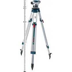
ᢺ⍻䟿ԚಘкⲴй㝊᧕ཤ14㻵ޕй㝊Ⲵ㷪ᵶѝDŽᤗ㍗й㝊Ⲵ
പᇊ㷪эᶕപᇊྭ⍻䟿ԚಘDŽ
ݸ㋇⮕Ⲵ䘋㹼ⶴ߶ᐕˈ൘⸝䐍ԕᨀ䎧й㝊ᶕᩜࣘԚಘˈѪ
Ҷ䚯ݽ൘ᩜ䘀ѝᦏൿԚಘˈᗵ享ԕⴤ・Ⲵᯩᔿᨀᩪй㝊ˈнԕᢺ
й㝊⁚䶐൘㛙кDŽ
3.1 ፏضᓓ
3.2 ඳᔮᏕࡥଷ
֯⭘㝊㷪э䖞9ṑ߶ԚಘDŽ䈳ᮤ㝊㷪э䖞䇙ശ≤⌑ѝⲴ≄⌑սҾަ
ѝᗳDŽ˄മ1˅
ݸ䖜ࣘ㝊㷪э䖞
A઼B䇙≄⌑〫ࣘࡠ䘉є⛩ѝཞⲴս㖞ˈ᧕⵰൘䖜ࣘ
㝊㷪э䖞
C㠣≄⌑〫ࣘࡠശ≤⌑ѝᗳѪ→DŽ
4
Ԉ؍ٵࡊӕњ
മ1
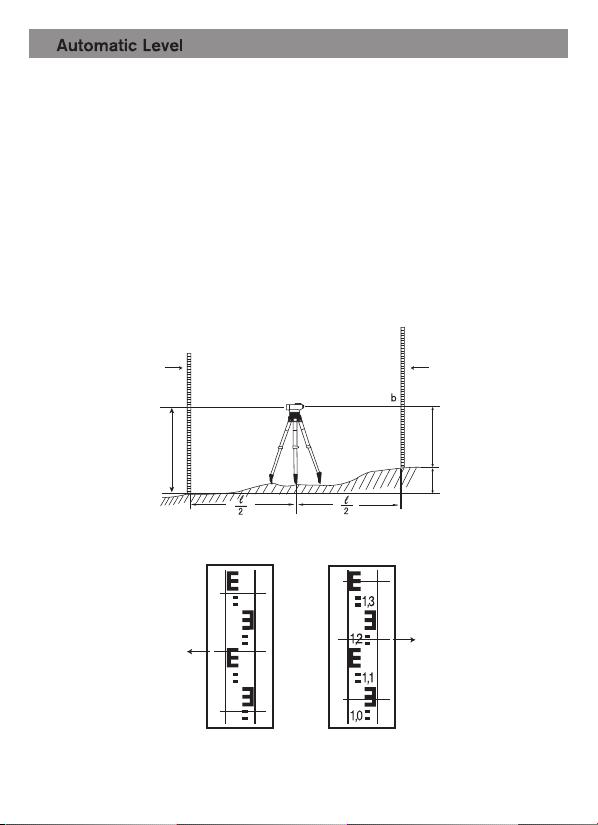
ሶԚಘᆹ㖞Ҿ㻛⍻⛩AǃBⲴѝ䰤DŽ˄മ2˅
4.1 ܪܶ
ܪজจ
5
Ԉ؍ٵࡊӕњ
ሶ≤߶ቪԕⴤⲴᯩᔿㄆ・ҾA⛩ˈሶԚಘ㚊❖ᒦᢺᆇэ䈳ᮤࡠ≤
߶ቪⲴѝཞˈ䇠ᖅлᆇэⲴѝ㓯൘≤߶ቪᡰ൘ս㖞Ⲵᓖ٬aDŽ
ሶ≤߶ቪԕⴤⲴᯩᔿㄆ・Ҿ%⛩ˈሶԚಘ㚊❖ᒦᢺᆇэ䈳ᮤࡠ≤
߶ቪⲴѝཞˈ䇠ᖅлᆇэⲴѝ㓯൘≤߶ቪᡰ൘ս㖞Ⲵᓖ٬bDŽ
儈ᐞh=1.78ˉ1.215=0.565㊣DŽ
ഴ
ഴ
≪ተ ≪ተ
A
a(1.78)
a(1.78)
b(1.215)
b(1.215)
h
B
1,9
1,8
1,7
1,6
ഴ
˄മ3˅
˄മ4˅

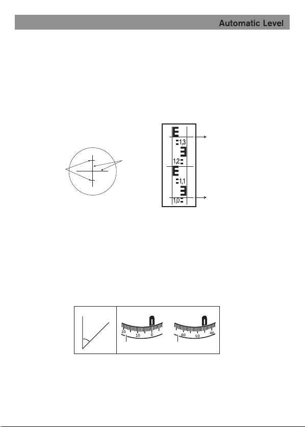
ⶴ߶≤߶ቪˈ䇠ᖅл㿶䐍э˄മ5˅൘≤߶ቪᡰ൘ս㖞Ⲵᓖ٬DŽ
ሶ㿶䐍эⲴ儈ᓖᐞ٬҈ˈᡰᗇⲴ٬ׯᱟӾԚಘࡠ≤߶ቪⲴ䐍DŽ
4.2 ܪீಏ
6
Ԉ؍ٵࡊӕњ
㿼䐓ѓ
㿼䐓ѓр㓵
㿼䐓ѓс㓵
ᆍѓ
˄മ6˅
ᢺ⍻䟿Ԛಘሩ߶⛩Aˈ䖜ࣘᓖⴈ2䇙ᓖĀ0āሩ߶ᓖⴈᤷ⽪⡼3DŽ
ᢺ⍻䟿Ԛಘሩ߶⛩Bˈ↔ᰦ䇠ᖅлᓖⴈᤷ⽪⡼3лⲴᓖDŽ
4.3 ࢘ܪ
˄മ7˅
˄മ7˅
മк⍻ᗇⲴ䐍ᱟ˖(1.347-1.042)×100=30.5㊣
മк⍻ᗇⲴ䀂ᓖᱟ˖45e
1.347
1.042
ഴ
ഴ
ഴ
A B
A
B
x
e
ᓖⴈᤷ⽪⡼
ᓖⴈ ᓖⴈ
ᓖⴈᤷ⽪⡼
˄മ8˅
˄മ9˅
֯⭘Ԛಘѻࡽᡆ㓿䗷䮯ᰦ䰤Ⲵ䘀䗃ѻˈ䜭ᗵ享Ựḕ⍻䟿ԚಘⲴᒣ㋮
ᓖ઼ᱮ⽪㋮ᓖDŽ
֯⭘㝊㷪э䖞
9ṑ߶ԚಘDŽ䈳ᮤ㝊㷪э䖞䇙≄⌑սҾശ≤⌑ⲴѝᗳDŽ
䖜㝊㷪э䖞
9ˈ֯≄⌑ѝᗳ〫ࣘˈٿ〫䟿Ѫ1/2DŽ
֯⭘ޝ䀂ᢣ䈳ᮤ≤⌑㷪䪹ˈ֯≄⌑〫㠣ശ≤⌑ⲴѝᗳDŽ
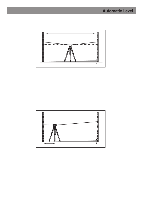
Ựḕᰦᗵ享а⇥30㊣䮯Ⲵ⍻䟿䐍DŽᢺԚಘ᭮㖞൘ѝ䰤ս㖞ˈ൘⍻
䟿Ⲵєㄟ࠶࡛᭮㖞≤߶ቪA઼≤߶ቪBDŽ˄മ10˅
࠶࡛䇠ᖅєњ≤߶ቪкⲴ儈ᓖˈ䇑㇇ࠪᐞ٬d˗ণa1˄≤߶ቪAкⲴ儈
ᓖ˅઼b1˄≤߶ቪBкⲴ儈ᓖ˅Ⲵᐞ䐍DŽ
䟽༽к䘠↕僔ˈⴤ㠣ᵋ䘌䮌䖜㠣ԫօᯩᰦ≄⌑㓸༴Ҿശ≤⌑Ⲵѝ
ᗳս㖞DŽ
ሶԚಘ䖜180eˈ≄⌑ᓄ൘ശ≤⌑Ⲵѝᗳˈྲٿˈࡉ䴰㾱ṑ↓DŽ
5.1 ႈଈܱ
5.2 ႈቧᒫ
5.3 iଈܱ
ፏ࠲ଈܱᏕࡥᒩ
7
Ԉ؍ٵࡊӕњ
ഴ ഴ
ᰁ䖢㝐㷰ѓᢁ䖤 䈹᮪≪⌗㷰䪿
ഴ
ഴ
ֻᆀ˖a1=1.937㊣b1=1.689㊣ࡉa1-b1=0.248㊣=d
ֻᆀ˖a2=1.724㊣d=0.248㊣ࡉa2-d=1.476㊣=b2’
20X/22X: ⍻䟿ᰦˈ儈ᓖb2Ⲵ٬ᓄ䈕ᱟ1.476㊣±6∛㊣
24X/26X/28X/32X: ⍻䟿ᰦˈ儈ᓖb2Ⲵ٬ᓄ䈕ᱟ1.476㊣±3∛㊣
ᢺԚಘ᭮㖞൘䐍≤߶ቪA㓖1㊣༴ˈˈ䇠ᖅ儈ᓖ٬a2˄≤߶ቪAк
Ⲵ儈ᓖ˅DŽ
䇑㇇b2’=a2-dˈ䇠ᖅ儈ᓖ٬b2˄≤߶ቪBкⲴ儈ᓖ˅ˈྲb2’оb2
Ⲵᐞᔲ䎵䗷6∛㊣˄20X/22X˅ᡆ3∛㊣˄24X/26X/28X/32X˅ࡉ䴰
㾱䘋㹼ṑ↓DŽ
8
Ԉ؍ٵࡊӕњ
BA
30 m
a1
a2
a1-b1=d
a2-d=b2’
b1
d
BA
1 m
b2
d

ፏ࠲ᆬᏕډጞ
лⴞ䮌㖙ˈ֯⭘᭩↓䪸ˈᵍ亪ᰦ䪸ᡆ䘶ᰦ䪸Ⲵᯩ䖜ࣘṑ↓㷪䪹ˈ䇙
≤߶ቪBкⲴ儈ᓖ⍻䟿٬b2оb2’ㅖѪ→DŽ
Ԛಘᓄ㋮ᗳ㔤ᣔ؍ޫˈԕ؍䇱Ԛಘ㋮ᓖ৺֯⭘᭸⦷DŽ
⍻䟿ᐕᆼᡀˈሶԚಘ䜘㺘䶒⌱ᒢ߰ˈ᭮ޕԚಘ㇡DŽ
ݹᆖ䴦Ԧ㺘䶒֯⭘䖟∋ࡧǃ䮌ཤ㓨ᬖˈᗼ⭘ᤷ䀖᪨䮌⡷DŽ
Ԛಘྲᴹ᭵䳌ᡆᦏൿˈ享ᴹ⟏ᚹԚಘ㔃ᶴᒦᴹаᇊ؞⨶㓿傼ⲴᢰᵟӪ
ઈ䘋㹼Ự؞ˈᡆ䘱ᖰԚಘࡦ䙐ল؞⨶ˈ⾱→㠚ᢃᔰ⍻䟿ԚಘDŽ
Ԛಘ㇡༷ᴹᒢ⠕ࡲа㺻ˈᆳ㜭ཏࠍ㔃㇡ѝⲴ⒯≄ˈ䈧ᇊᰦᴤᦒᒢ⠕
ࡲ㺻DŽ
ԚಘᓄۘᆈҾᒢ⠕ǃ⌱ǃ䙊仾㢟ྭⲴൠᯩDŽ
5.4 iቧᒫ
9
Ԉ؍ٵࡊӕњ
ᔢቆࠓ
༷⌘˖400gonᓖⴈǃ5/8ąй㝊䘎᧕ቪረӵࠪ䘹⭘DŽ
ກᯉԚಘ㇡1
⍻䟿Ԛಘ1
᭩↓䪸1
ޝ䀂ᢣ1
֯⭘䈤᰾Җ1
䫵䭔1
ᒢ⠕ࡲ1

Notes:
before start to operate the instrument or after long transportation, the leveling
and display accuracy must be checked first.
Protect the instrument against moisture, and keep the instrument away from
direct sunshine.
Never leave the instrument in vehicles for a long time.
If the temperature has difference between the working spot and reserved
place, please keep the instrument into case for a while until it suit to the
working temperature before putting into operation.
The measuring accuracy of the instrument can be impaired if exposing it
under extreme temperatures or variations in temperature.
Avoid of any impact to or dropping of the instrument onto the ground.
Place the instrument into the provided carrying case during long
transportation. The instrument should be avoid of extreme extrusion, bumping
and shaking during transportation. Ensure that instrument is correctly placed
in the transport case (When placing the instrument into case, the compensator
should be locked, otherwise, it could be damaged in case of intense movement.)
This instrument only allow the qualified specialists to repair and ensure of
using the original spare parts. No one allow to separate the unit except of
professional to avoid of any unnecessary damaged.
We appreciate of your purchasing our autolevel series. In order to help you fully
explore the instrument features, please read this manual carefully and save these
instructions properly for future reference.
Preface

Index
1.Technical Data
1.1 DAL20-32 Series & DAL20-32N Series
technical data....................................................................
1.2 DAL20-32P Series & DAL20-32H Series
technical data....................................................................
2.The instrument parts name
3.Operation
3.1 Setting up
3.2 Aiming and focusing
4.1 measuring height
4. Measuring function
4.2 measuring distance
4.3 measuring angles
5.1 checking the circular vial
5.2 adjusting the circular vial
5.3 checking i angle
5. Checking and adjusting instrument
6. Maintenance and Service
7. Packing list
5.4 adjusting i angle
10
10
11
12
13
13
13
14
14
15
15
16
16
16
16
18
18
18
EN

10
1. Technical Data
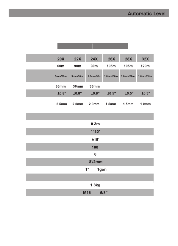
1.1 DAL20-32 series & DAL20-32N series technical data
DAL20-32 series DAL20-32N series
Height accuracy
for an individual
measurement
Magnification
Working Range
Clear objective
aperture
Compensator
setting accuracy
Standard Devia-
tion for 1 km
Telescope Image erect
Short focusing distance
Field of view
The working range of compensator
Stadia ratio
or
or
Yes
Stadia addition
Accuracy of circular vial
Horizontal circle graduation
Water resident
Net weight
Tripod mount thread
double run leveling
11
1.2 DAL20-32P series &DAL20-32H series technical data
DAL20-32P series DAL20-32H series
Height accuracy
for an individual
measurement
Magnification
Working Range
Clear objective
aperture
Compensator
setting accuracy
Standard Devia-
tion for 1 km
Telescope Image erect
Short focusing distance
Field of view
The working range of compensator
Stadia ratio
or
or
Yes
Stadia addition
Accuracy of circular vial
Horizontal circle graduation
Water resident
Net weight
Tripod mount thread
double run leveling
40mm 40mm 40mm
12
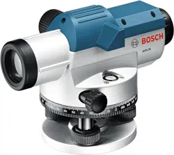
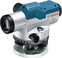
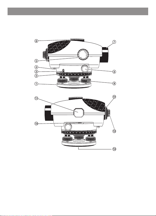
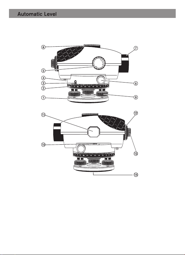
1.base plate
Other series Autolevel please refer to introduction on this page
2.horizontal circle
3.horizontal circlereference mark
4.compensator lock
5.focusing adjusting knob
6.optical peep sight
7.objective lens
8.horizontal drive screw
9.leveling screw 14.tripod mount 5/8"
(on the rear side)
10.circular vial
11.bubble observe mirror
12.eyepiece cover
13.eyepieces focusing knob
2. The instrument parts description
D
AL 32P
13
3. Operation
1. Set up the tripod stable and safe against tipping over or slipping off, and adjust
tripod to the position of user's eyes level.
1. take away the objective lens cover 7, let the telescope shoot toward a bright object or
hold a white sheet of paper in front of the objective lens 7, then turn the eyepieces 13
till dark black crosshair can be seen sharply.
2. Direct the telescope towards the leveling rod, it may required optical peep sight 6 to aim
if necessary.
3. Turn focusing knob 5 till the graduation field of the leveling rod appears sharply.
4. Align the crosshair exactly to the center of the leveling rod by turning the horizontal
drive screw 8.
2. Place the instrument via the tripod mount 14 onto the male thread of the tripod
and screw the unit tight with locking screw of the tripod.
3. Roughly level the tripod, over the short distance, the instrument can be carried
by lifting the tripod. To ensure that the instrument is not damaged during this
process the tripod must be held vertically and should not be lengthwise over the
shoulder.
3.1 Setting up
3.2 Aiming and focusing
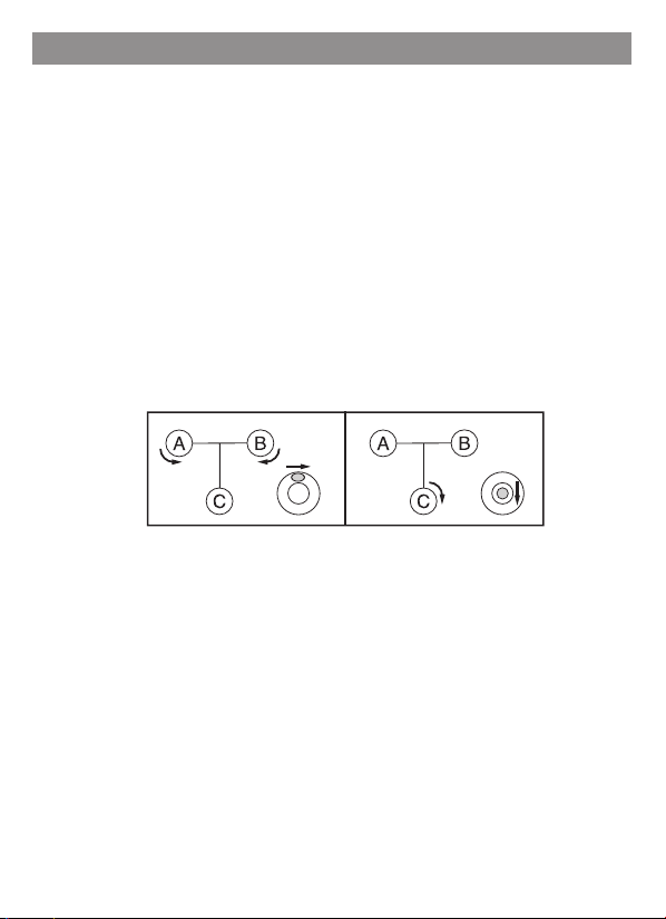
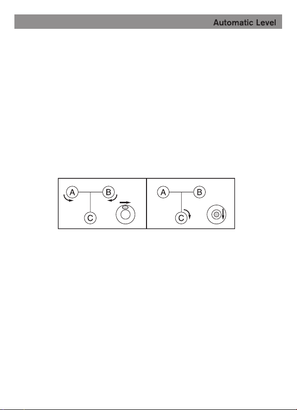
4. Align the instrument with leveling screw 9 so that the air bubble is in the center
of the circular vial (see fig.1)
turn the first two leveling screws A and B to move the air bubble so that it is centered
between the two leveling screws, then turn the leveling screw C until the air bubble is
in the center of circular vial.
fig.1
14
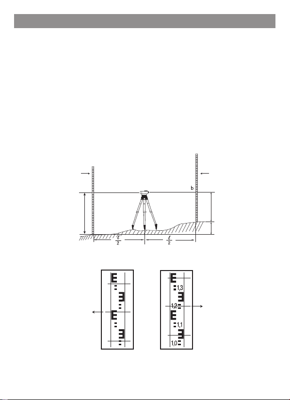
1. Place the instrument to the center of point of A and B ( see fig2.)
4.1 Measuring Height
4. Measuring Functions
2. Erect the leveling rod to the point of A vertically, focus the instrument against the
leveling rod and adjust the crosshair to match the center of leveling rod, record the
height value a of the leveling rod at the centre line of the crosshair. (see fig.3)
3. Erect the leveling rod to the point of B vertically, focus the instrument against the
leveling rod and adjust the crosshair to match the center of leveling rod, record the
height value b of the leveling rod at the center line of crosshair. (see Fig.4)
4. The Height Difference h=1.78-1.215=0.565m
fig.2
Fig.3
leveling rod leveling rod
A
a(1.78)
a(1.78)
b(1.215)
b(1.215)
h
B
1,9
1,8
1,7
1,6
Fig.4
15
1. Aiming the leveling rod, record the value of upper and lower stadia hair( see fig.5)
against the position of leveling rod (see fig.6)
2. Multiply the difference of both heights of stadia hair by 100 to receive the distance
value from the leveling rod to the instrument.
4.2 Measuring Distance
stadia hair
upper line of stadia hair
lower of stadia hair
cross hair
1. Shoot the instrument toward A, rotate the horizontal circle 2 with "0" point toward the
reference mark 3. (see fig.7 )
2. Shoot the instrument toward B, read off the angle value at the reference mark 3 of
horizontal circle. (see fig.7)
4.3 Measuring Angles
distance measured in the figure: (1.347-1.042)x 100=30.5m
the measured angle in figure: 45°
1.347
1.042
fig.6
fig.7
fig.5
A B
A
B
x
e
horizontal circle
reference mark
horizontal circle
horizontal circle
reference mark
horizontal circle

16
Before using the instrument or after long transportation, the leveling accuracy and
indication accuracy.
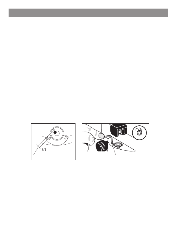
1. Adjust the instrument with leveling screw knob 9, so that the air bubble is in the center
of circular vial.
1. Rotate the leveling screw knob 9 to ensure the air bubble moving toward to the
center of circular bubble vial, the deviation should be at 1/2 between the center
and the end position(see fig.8)
2. Use align wrench turn the two adjustment screws till the air bubble moving to the
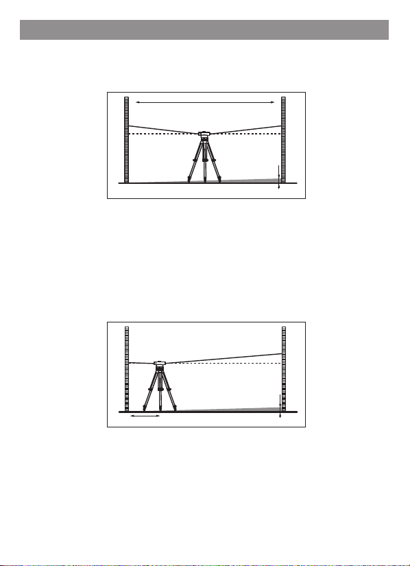
center of circular bubble vial.(see fig.9)
1. Checking should be done at a distance of 30m. Place the instrument in the center of
this distance, put 2 leveling rod at the both end of measuring distance A and B
separately.˄see fig.10)
2. Read off the heights of this two leveling rod, calculate the difference d; that is the
difference between a1(the height of leveling rod A) and b1(the height of leveling rod B).
3. Repeat the above step till the air bubble keep in the center of circular bubble vial
no matter which direction the telescope turned.
2. Rotate the unit by 180e, the air bubble should keep in center, if the air bubble moves
out of center, the circular bubble vial must be readjusted.
5.1 Check Circular Bubble Vial
5.2 Adjusting Circular Bubble Vial
5.3 Checking i angle
5. Checking and Adjusting
fig.8 fig.9
rotate leveling screw knob bubble adjusting screw
17
Fig.10
Fig.11
Example: a1=1.937m b1=1.689m so a1-b1=0.248=d
Example: a2=1.724m d=0.248 so a2-d=1.476=b2'
when measuring 20x/22x, the height b2 should be 1.476m+/-6mm
when measuring 24/26/28/32x, the height b2 should be 1.476=+/-3mm
3. Place the instrument to the position of 1m away from leveling rod A, read height a2
( the height of leveling rod A)
4. Calculate b2'=a2-d, then record the height b2( the height of leveling rod B), if the
deviates value between b2'and b2 over 6mm˄20x/22x) or 3mm(24x/26x/28x/32x),
the crosshair must be readjusted.
BA
30 m
a1
a2
a1-b1=d
a2-d=b2’
b1
d
BA
1 m
b2
d

18
6. Maintance and Service
take off the eyepiece cover, use adjusting pin turn adjusting screw clockwise or
counterclockwise till the heights value b2 and b2' on leveling rod B are same.
Carefully use and maintain the unit, can guarantee the instrument accuracy and
efficiency.
1. After measuring, wipe clean all the surface of the instrument and put into the
carrying case.
2. Dust all optical parts with a soft brush and clean the lens with lens paper. Never
touch the lens with your fingers.
3. If the instrument failed in function or damaged, repair or check should be done by
experienced technician who fully understand the unit structure or returned to the
factory for repair. Do not open the instrument by yourself.
4. A bag of silica gel dryer is included in the case for the removal of residual moisture.
Renew the bag of silica gel regularly.
5. The unit should be kept in a dry, clean, dust-free and air-flow condition with low
humidity.
5.4 adjust the i angle
Screw on eyepiece cover again.
7. Packing List
Note: 400gonǃ5/8" tripod only for export purpose
Plastic Carrying Case
The Unit
Adjusting Pin
Hexagonal Wrench
Instruction Manual
Plumb
Silica Dry Gel.
1
1
1
1
1
1
1