
DS525 MOBILELOCK
TM
Equipment
Power Adapter
For use only with the DewAlt Ds500.
not For use on equipment sources other
thAn 12 V or 24 V.
WARNING: Read and understand all instructions and
warnings for this product. In addition, read and follow all
instructions and warnings provided with the DS500 MOBILELOCK™
GPS Locator with Anti-Theft Alarm (Base Unit).
CAUTION: POTENTIAL EQUIPMENT MALFUNCTION OR
FAILURE. Do not operate with a damaged power supply cord or plug.
Damage to the hardware may occur. Protect the power supply cord
from cutting, fraying and other damage particularly at plugs and the
point where they exit from the product. Do not pull on cords or cables.
If a cord or plug is damaged, have it replaced immediately.
CAUTION: POTENTIAL EQUIPMENT MALFUNCTION OR
FAILURE. Do not remove or by-pass the fuse in the cord of the
DS525. Do not remove or by-pass any overload protection device
currently in the equipment/vehicle.
Important
• This product should be installed by a professional. Refer to the
installation instructions in this manual and the instruction sheet
included with the connectors.
• This product is not user serviceable. There are no user serviceable
parts inside the product. Servicing at a DeWALT authorized service
center is required to avoid damage to the product. Unauthorized
service will void the warranty.
• MOBILELOCK™ is a trademark of SITELOCK LLC. All other
trademarks in this manual are the properties of their respective
owners.
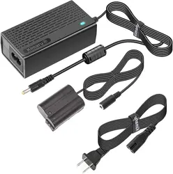
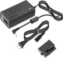
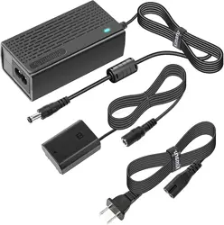
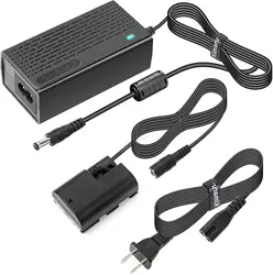
Product Overview
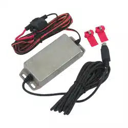
The DS525 Equipment Power Adapter is designed to use a 12 V or
24 V battery to provide power to the DS500 MOBILELOCK™. The
DS525 consists of an input cable, a DC to DC converter, an output
cable and connectors. The DS500 will recharge regardless of whether
the heavy equipment or vehicle is running.
Components (Fig. 1)
A. Black cable D. Fuse
B. Red cable E. Output cable
C. Connectors
Installation (Fig. 2, 3)
WARNING: To reduce the risk of personal injury, turn off
ignition switch.
note: If the DS525 is wired incorrectly, it will not work. Neither the
DS525 nor the equipment’s electrical system will be damaged.
1. Determine the positive (+) and negative (-) wires to be spliced
coming from the 12 V or 24 V battery of the equipment. The
connections to be used should be independent of the ignition
switch.
2. The negative connection should be made to a ground or negative
wire. Slide the negative (-) wire from the battery supply of the
equipment into the pass through slot of the second connector.
3. Insert the black cable (A) into the half-through slot of the
connector.
4. Use pliers to press metal “U” contact down into the connector
as shown in Figure 2. As the “U” contact is pressed into the
connector, it grasps conductor as it displaces insulation.
5. Bend plastic cover and snap closed as shown in Figure 3.
6. The positive connection should be made with a wire that has 12 V
or 24 V when the ignition is off. Slide the positive (+) wire from the
battery supply of the equipment into the pass-through slot of the
connector. The cable must be protected by a fuse installed directly
next to the power connection. Do not cut the cable. If a shorter
cable is desired, wrap the cable with a cable tie.
7. Insert the red cable (B) into the half-through slot of the
connector.
8. Use pliers to press metal “U” contact down into connector as
shown in Figure 2. As the “U” contact is pressed into connector, it
grasps conductor as it displaces insulation.
9. Bend plastic cover over and snap closed as shown in Figure 3.
10. Mount the DS525 using the screw holes. Do not drill or screw
into vehicle system components such as wires, hoses, etc.
note: The DS500 draws a very small amount of current while
charging. If the equipment/vehicle is not started over an extended
period of time, the equipment/vehicle battery could become
discharged.
Mounting
• Install the DS525 when the equipment/vehicle is on level ground
and the brake is on. Turn off the engine of the equipment/
vehicle.
• Mount in a location to protect from damage.
• Mount securely to prevent the DS525 from coming loose during
equipment/vehicle operation.
• Do not mount near engine or other extreme heat source.
• Do not drill or screw into vehicle system components such as
wires, hoses, etc.
• After the DS525 is installed, the battery of the DS500
MOBILELOCK™ charges for up to 24 hours. During this time,
an increase in energy may cause the DS525 to be warm to the
touch.
SITELOCK LLC, 701 East Joppa Road, Baltimore, MD 21286 (JUL07) Form No. 654664-00 DS525 Copyright © 2007 DeWALT
E
B
FIG. 1
A
D
C
FIG. 3
FIG. 2

DS525 MOBILELOCK
TM
Equipment
Power Adapter
For use only with the DewAlt Ds500.
not For use on equipment sources other
thAn 12 V or 24 V.
WARNING: Read and understand all instructions and
warnings for this product. In addition, read and follow all
instructions and warnings provided with the DS500 MOBILELOCK™
GPS Locator with Anti-Theft Alarm (Base Unit).
CAUTION: POTENTIAL EQUIPMENT MALFUNCTION OR
FAILURE. Do not operate with a damaged power supply cord or plug.
Damage to the hardware may occur. Protect the power supply cord
from cutting, fraying and other damage particularly at plugs and the
point where they exit from the product. Do not pull on cords or cables.
If a cord or plug is damaged, have it replaced immediately.
CAUTION: POTENTIAL EQUIPMENT MALFUNCTION OR
FAILURE. Do not remove or by-pass the fuse in the cord of the
DS525. Do not remove or by-pass any overload protection device
currently in the equipment/vehicle.
Important
• This product should be installed by a professional. Refer to the
installation instructions in this manual and the instruction sheet
included with the connectors.
• This product is not user serviceable. There are no user serviceable
parts inside the product. Servicing at a DeWALT authorized service
center is required to avoid damage to the product. Unauthorized
service will void the warranty.
• MOBILELOCK™ is a trademark of SITELOCK LLC. All other
trademarks in this manual are the properties of their respective
owners.
Product Overview
The DS525 Equipment Power Adapter is designed to use a 12 V or
24 V battery to provide power to the DS500 MOBILELOCK™. The
DS525 consists of an input cable, a DC to DC converter, an output
cable and connectors. The DS500 will recharge regardless of whether
the heavy equipment or vehicle is running.
Components (Fig. 1)
A. Black cable D. Fuse
B. Red cable E. Output cable
C. Connectors
Installation (Fig. 2, 3)
WARNING: To reduce the risk of personal injury, turn off
ignition switch.
note: If the DS525 is wired incorrectly, it will not work. Neither the
DS525 nor the equipment’s electrical system will be damaged.
1. Determine the positive (+) and negative (-) wires to be spliced
coming from the 12 V or 24 V battery of the equipment. The
connections to be used should be independent of the ignition
switch.
2. The negative connection should be made to a ground or negative
wire. Slide the negative (-) wire from the battery supply of the
equipment into the pass through slot of the second connector.
3. Insert the black cable (A) into the half-through slot of the
connector.
4. Use pliers to press metal “U” contact down into the connector
as shown in Figure 2. As the “U” contact is pressed into the
connector, it grasps conductor as it displaces insulation.
5. Bend plastic cover and snap closed as shown in Figure 3.
6. The positive connection should be made with a wire that has 12 V
or 24 V when the ignition is off. Slide the positive (+) wire from the
battery supply of the equipment into the pass-through slot of the
connector. The cable must be protected by a fuse installed directly
next to the power connection. Do not cut the cable. If a shorter
cable is desired, wrap the cable with a cable tie.
7. Insert the red cable (B) into the half-through slot of the
connector.
8. Use pliers to press metal “U” contact down into connector as
shown in Figure 2. As the “U” contact is pressed into connector, it
grasps conductor as it displaces insulation.
9. Bend plastic cover over and snap closed as shown in Figure 3.
10. Mount the DS525 using the screw holes. Do not drill or screw
into vehicle system components such as wires, hoses, etc.
note: The DS500 draws a very small amount of current while
charging. If the equipment/vehicle is not started over an extended
period of time, the equipment/vehicle battery could become
discharged.
Mounting
• Install the DS525 when the equipment/vehicle is on level ground
and the brake is on. Turn off the engine of the equipment/
vehicle.
• Mount in a location to protect from damage.
• Mount securely to prevent the DS525 from coming loose during
equipment/vehicle operation.
• Do not mount near engine or other extreme heat source.
• Do not drill or screw into vehicle system components such as
wires, hoses, etc.
• After the DS525 is installed, the battery of the DS500
MOBILELOCK™ charges for up to 24 hours. During this time,
an increase in energy may cause the DS525 to be warm to the
touch.
SITELOCK LLC, 701 East Joppa Road, Baltimore, MD 21286 (JUL07) Form No. 654664-00 DS525 Copyright © 2007 DeWALT
E
B
FIG. 1
A
D
C
FIG. 3
FIG. 2

2
Specifications
Power: 12 Volt or 24 Volt lead acid battery
Current: 300 mA (output)
Operating Temperature: -4˚ to 122˚F (-20˚ to +50˚C)
Storage Temperature: -40˚ to 185˚F (-40˚ to +85˚C)
Internal Fuse: 5 A
External Fuse: 5 A
Contact
If you have any questions or comments about this product, call us toll
free at 1-877-456-LOCK (1-877-456-5625) or visit www.dewalt.com.
Full One Year Warranty
The DS525 is warranted for one year from the date of purchase.
We will repair, without charge, any defects due to faulty materials
or workmanship. For warranty repair information, visit www.dewalt.
com/mobilelock or call 1-877-456-LOCK (1-877-456-5625). This
warranty does not apply to accessories or damage caused where
repairs have been made or attempted by others. This warranty gives
you specific legal rights and you may have other rights which vary in
certain states or provinces.
Free wArning lAbel replAcement: If your warning labels
become illegible or are missing, call 1-800-4-DeWALT for a free
replacement.
Adaptateur de courant pour équipement
DS525 MOBILELOCK
TM
usAge préVu pour le moDèle Ds500 DewAlt.
ne pAs utiliser sur l’équipement Dont lA source
D’AlimentAtion n’est pAs De 12 V ou De 24 V.
AVERTISSEMENT : lire et comprendre les directives et les
avertissements pour ce produit. En outre, lire et suivre les
directives et avertissements fournis avec le localisateur de GPS
DS500 MOBILELOCK™ accompagné du système d’alarme antivol
(unité de base).
ATTENTION : RISQUE DE DYSFONCTIONNEMENT OU DE
DÉFAILLANCE DE L’APPAREIL. Ne pas faire fonctionner le bloc
d‘alimentation lorsque l’un de ses cordons ou fiches est endommagé.
Une détérioration du matériel pourrait se produire. Éviter que le
cordon d’alimentation ne soit coupé, effiloché ou endommagé surtout
à l’emplacement de la fiche et à la sortie de l’appareil. Ne pas tirer sur
les cordons ou les câbles. Si un cordon ou la fiche sont endommagés,
les remplacer sur-le-champ.
ATTENTION : RISQUE DE DYSFONCTIONNEMENT OU DE
DÉFAILLANCE DE L’APPAREIL. Ne pas retirer le fusible ni ne
le faire dériver dans le cordon du DS525. Ne pas retirer ni faire
dériver tout dispositif de protection de surcharge se trouvant dans
l’équipement ou le véhicule.
Important
• Ce produit doit être installé par un professionnel. Consulter les
directives d’installation dans ce manuel et la feuille d’instruction
comprise avec les connecteurs.
• Ce produit n’est pas réparable par l’utilisateur. Aucune pièce à
l’intérieur de cet appareil ne peut être réparée par l’utilisateur.
Pour éviter une détérioration de l’appareil, confier les réparations
à un centre de réparation agréé DeWALT. Une réparation non
autorisée annulera la garantie.
• MOBILELOCK™ est une marque déposée de SITELOCK
LLC. Toutes les autres marques mentionnées dans ce manuel
appartiennent à leurs propriétaires respectifs.
Aperçu du produit
L’adaptateur de courant pour équipement DS525 est conçu pour
utiliser une pile de 12 V ou de 24 V afin d’alimenter le DS500
MOBILELOCK™. Le DS525 est constitué d’un câble d’entrée, d’un
convertisseur ce c.c. à c.c., d’un câble de sortie et de connecteurs.
Le DS500 recharge l’équipement ou le véhicule qu’il soit en marche
ou non.
Composants (fig. 1)
A. Câble noir D. Fusible
B. Câble rouge E. Câble de sortie
C. Connecteurs
Installation (fig. 2, 3)
AVERTISSEMENT : pour réduire le risque de blessures person-
nelles, fermer le contact.
remArque : si le DS525 est mal câblé, il ne fonctionnera pas.
Ni le DS525 ni le circuit électrique de l’équipement ne seront
endommagés.
1. Déterminer le fil positif (+) et le fil négatif (-) à épisser en prov-
enance de la pile de 12 V ou de 24 V de l’équipement. Les
connexions à utiliser doivent être indépendantes du contacteur
d’allumage.
2. La connexion négative doit être liée à la masse ou à un fil négatif.
Glisser le fil négatif (-) de la pile de l’équipement dans la fente du
deuxième connecteur.
3. Insérer le câble noir (A) dans la fente à ouverture partielle du con-
necteur.
4. Utiliser une pince pour enfoncer le contact métallique en U dans
le connecteur comme le montre la figure 2. Le contact en U étant
enfoncé dans le connecteur, il a une prise sur le conducteur, car
il déloge l’isolant.
5. Plier le couvercle en plastique et l’enclencher pour le fermer
comme le montre la figure 3.
6. La connexion positive doit être liée à un fil de 12 V ou de 24 V
lorsque le contact est fermé. Glisser le fil positif (+) de la pile de
l’équipement dans la fente complète du connecteur. Le câble doit
être protégé par un fusible posé directement à côté du raccord
d’alimentation. Ne pas couper le câble. S’il faut un câble plus
court, enrouler le câble d’une attache de câble.
7. Insérer le câble rouge (B) dans la fente partielle du connecteur.
8. Utiliser une pince pour enfoncer le contact métallique en U dans
le connecteur comme le montre la figure 2. Le contact en U étant
enfoncé dans le connecteur, il a une prise sur le conducteur, car
il déloge l’isolant.
9. Plier le couvercle en plastique et l’enclencher pour le fermer
comme le montre la figure 3.
10. Fixer le produit DS525 à l’aide des trous de vis. Ne pas percer ni
visser dans les composants de circuits du véhicule comme les fils,
les flexibles, etc.
remArque : le DS500 tire très peu de courant durant la charge.
Si l’équipement ou le véhicule n’a pas été mis en marche durant une
période prolongée, la pile de l’équipement ou la batterie du véhicule
pourrait être déchargée.
Montage
• Poser le DS525 une fois que l’équipement ou le véhicule repose
sur un sol au niveau et que le frein est mis. Éteindre le moteur de
l’équipement ou du véhicule.
• Monter l’appareil à un endroit qui le protège contre les dom-
mages.
• Bien fixer le DS525 afin d’éviter qu’il devienne lâche durant le
fonctionnement de l’équipement ou le véhicule.
• Ne pas fixer l’appareil près du moteur ou d’une autre source de
chaleur extrême.

3
• Ne pas percer ni visser dans les composants de circuits du véhi-
cule comme les fils, les flexibles, etc.
• Après avoir posé le DS525, la pile du DS500 MOBILELOCK™
se charge pour une durée maximale de 24 heures. Durant cette
période, l’énergie accrue dégagée peut rendre le DS525 chaud au
toucher.
Fiche technique
Courant : pile 12 V ou 24 V au plomb
Courant : 300 mA (sortie)
Température de
fonctionnement : -20 ˚C à +50 ˚C (-4 ˚F à 122 ˚F)
Température d’entreposage : -40 ˚C à +85 ˚C (-40 ˚F à 185 ˚F)
Fusible interne : 5 A
Fusible externe : 5 A
Contact
Si vous avez des questions ou des commentaires sur ce produit,
composer sans frais le 1-877-456-LOCK (1-877-456-5625) ou visitez
le site Web www.dewalt.com.
Garantie complète d’un an
Le DS525 est garanti pendant un an à partir de la date d’achat.
DeWALT réparera gratuitement toutes les défectuosités provoquées
par un défaut de matériel ou de fabrication. Pour plus de détails sur
les réparations sous garantie, visiter www.dewalt.com/mobilelock ou
composer le 1-800-456-LOCK (1-877-456-5625). Cette garantie ne
s’applique pas aux accessoires ni aux dommages causés par des
réparations réalisées ou tentées par des tiers. Cette garantie vous
accorde des droits légaux spécifiques et il est possible que vous ayez
d’autres droits qui varient d’un État ou d’une province à l’autre.
remplAcement grAtuit Des étiquettes
D’AVertissement : si les étiquettes d’avertissement deviennent
illisibles ou sont manquantes, composer le 1 (800) 4-DeWALT pour
en obtenir le remplacement gratuit.
Adaptador de corriente del equipo
DS525 MOBILELOCK
TM
pArA utilizAr únicAmente con DewAlt Ds500.
no Debe utilizArse en Fuentes De equipos que
no seAn De 12 V o 24 V.
ADVERTENCIA: Lea y comprenda todas las instrucciones y
advertencias para este producto. Además, lea y siga todas las
instrucciones y advertencias provistas con el Localizador GPS DS500
MOBILELOCK™ con alarma antirrobo (unidad de base).
PRECAUCIÓN: POSIBLE MAL FUNCIONAMIENTO O FALLA.
No lo utilice con un cable de suministro de energía o un enchufe
dañado. Pueden producirse daños en el equipo. Evite que el cable
de suministro de energía se corte, deshilache o sufra otro tipo de
daño, especialmente en los enchufes y en el punto en que sale del
producto. No tire del cable. Si el cable o el enchufe están dañados,
reemplácelos de inmediato.
PRECAUCIÓN: POSIBLE MAL FUNCIONAMIENTO O FALLA. No
quite ni anule el fusible del cable del DS525. No quite ni anule ningún
dispositivo de protección contra sobrecarga que se encuentre en el
equipo o vehículo.
Importante
• Este producto debe ser instalado por un profesional. Consulte las
instrucciones de instalación incluidas en este manual y la hoja de
instrucciones incluida con los conectores.
• El mantenimiento de este producto no puede ser realizado por el
usuario. Dentro de este producto no hay piezas a las que el usuario
pueda hacerles mantenimiento. Se requiere un mantenimiento
realizado en un centro de mantenimiento autorizado DeWALT a
fin de evitar daños al producto. El mantenimiento no autorizado
anulará la garantía.
• MOBILELOCK™ es una marca registrada de SITELOCK LLC.
Todas las demás marcas comerciales de este manual son
propiedad de sus respectivos dueños.
Descripción general del producto
El adaptador de corriente del equipo DS525 fue diseñado para
utilizar una batería de 12 V o 24 V que suministre energía al DS500
MOBILELOCK™. El DS525 consta de un cable de entrada, un
transformador de CC a CC, un cable de salida y conectores. El
DS500 se recarga incluso si el equipo o vehículo están funcionando.
Componentes (Fig. 1)
A. Cable negro D. Fusible
B. Cable rojo E. Cable de salida
C. Conectores
Instalación (Fig. 2, 3)
ADVERTENCIA: Para reducir el riesgo de lesiones personales,
apague el interruptor de ignición.
notA: Si el DS525 está mal cableado, no funcionará. Ni el DS525 ni
el sistema eléctrico del equipo sufrirán daños.
1. Separe el cable positivo (+) y el cable negativo (-) que se empal-
marán al salir de la batería de 12 V o 24 V del equipo. Las conex-
iones que se utilizarán deben ser independientes del interruptor
de ignición.
2. El cable negativo debe conectarse a un cable a tierra o a otro
cable negativo. Deslice el cable negativo (-) del suministro de la
batería del equipo por la ranura pasante del segundo conector.
3. Inserte el cable negro (A) en la ranura semipasante del conec-
tor.
4. Presione con pinzas el contacto metálico en “U” contra el conec-
tor, como se muestra en la Figura 2. Cuando se lo presiona contra
el conector, el contacto en “U” desplaza el aislamiento y sujeta al
conductor.
5. Doble la cubierta plástica y ciérrela a presión, como se muestra
en la Figura 3.
6. La conexión positiva debe realizarse con un cable que tenga 12 V
o 24 V cuando la ignición está apagada. Deslice el cable positivo
(+) del suministro de la batería del equipo por la ranura pasante
del conector. El cable debe protegerse con un fusible, instalado
justo al lado de la conexión de corriente. No corte el cable. Si
necesita acortar el cable, enróllelo con un sujetacables.
7. Inserte el cable rojo (B) en la ranura semipasante del conector.
8. Presione con pinzas el contacto metálico en “U” contra el conec-
tor, como se muestra en la Figura 2. Cuando se lo presiona contra
el conector, el contacto en “U” desplaza al aislamiento y agarra al
conductor.
9. Doble la cubierta plástica y ciérrela a presión, como se muestra
en la Figura 3.
10. Utilice los orificios de los tornillos para montar el DS525. No
dañe los componentes del sistema del vehículo, como cables,
mangueras, etc., al perforar o atornillar.
notA: Al cargar, el DS500 consume una cantidad muy pequeña de
corriente. Si el equipo o vehículo no se arranca durante un período
prolongado, la batería del equipo o vehículo puede descargarse.

4
Montaje
• Instale el DS525 con el equipo o vehículo a nivel del suelo y con
el freno puesto. Apague el motor del equipo o vehículo.
• Realice el montaje en un lugar donde no se vayan a producir
daños.
• Realice bien el montaje para evitar que el DS525 se afloje durante
el funcionamiento del equipo o vehículo.
• No realice el montaje cerca de un motor u otra fuente de calor
extremo.
• No dañe los componentes del sistema del vehículo, como cables,
mangueras, etc., al perforar o atornillar.
• Luego de instalar el DS525, la batería del DS500 MOBILELOCK™
se carga por hasta 24 horas. En este lapso, el incremento de
energía puede hacer que el DS525 esté caliente al tacto.
Especificaciones
Suministro de energía: Batería de plomo ácido de 12 ó 24 V
Corriente: 300 mA (salida)
Temperatura de
funcionamiento: De -20 ˚C a 50 ˚C (-4 ˚F a 122 ˚F)
Temperatura de
almacenamiento: De -40 ˚C a 85 ˚C (-40 ˚F a 185 ˚F)
Fusible interno: 5 A
Fusible externo: 5 A
Contacto
Si tiene alguna duda o comentario sobre este producto, llámenos al
número gratuito 1-800-456-LOCK (1-877-456-5625) o visite www.
dewalt.com.
Garantía completa de un año
El DS525 tiene una garantía de un año a partir de la fecha de compra.
Repararemos, sin cargo, cualquier defecto debido a fallas en los
materiales o la mano de obra. Para obtener información sobre las
reparaciones en garantía, visite www.dewalt.com/mobilelock o llame
al 1-800-456-LOCK (1-877-456-5625). Esta garantía no se extiende a
los accesorios o a los daños causados por terceros al intentar realizar
reparaciones. Esta garantía le concede derechos legales específicos;
usted goza también de otros derechos que varían según el estado o
provincia.
reemplAzo grAtuito De lAs etiquetAs De ADVertenciA:
Si sus etiquetas de advertencia se tornan ilegibles o faltan, llame al
1-800-4-DeWALT para que se las reemplacen gratuitamente.