Loading ...

HOW TO TEST RUN
Steps To Test Run Before Installation
IMPORTANT!
Wear gloves to protect against sharp edges.
Please follow these instructions to
TEST THE RANGE HOOD
BEFORE INSTALLATION
for any defect or shipping damage:
1. Remove the range hood and accessories from the
package carefully.
2. Place the range hood on a flat stable surface,
remove the baffle filter and check for any dents or
damages on the range hood body.
3. Remove the loosen parts if there's any.
4. Match the wires color and connect the wires as
instructed in the Wiring Diagram on the right
to
connect the Blower Unit to the Hood Unit.
5. Plug the range hood into a 120V AC power source.
Press the power button once and then any of the
speed buttons to turn it on.
6. Check each speed variation and pay attention to
the noise level to make sure there isn't any unusual
noise besides it coming from the wind blowing.
Press the Light Button to check the lights.
7. Verify all functions, as instructed in Page 10, are
working properly.
8. Refer to Range Hood Troubleshooting in Page 12 for
general issues and solutions.
Note
Please don't suspect that a range hood without protective
films is not a new product.
• The protective films on the body was removed to
complete the brush finished polishment on the
surface.
The Baffle Filters might be covered by protective films that
can be removed with the following steps:
• Soak the Baffle Filters into hot waters or use
heated air from a hair dryer to soften the films.
• Peel off the films from the corner.
Wiring Diagram
Important
• This Wiring Diagram is for connecting the wires from
RH-IT Hood Unit to an
Awoco Interior Blower Unit
(Model: RH-SP##-BLW) ONLY.
• If you have an
Awoco Exterior Blower Unit, or any
Blower Unit from other Brands
:
• DO NOT
CONNECT
the wires as shown in this
Wiring Diagram. Any damage from false wiring is
not covered by the warranty.
• Refer to your Blower Unit's USER MANUAL
for
how to properly connect the wires.
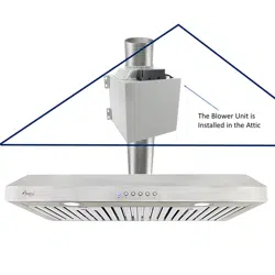
Ceiling
Duct
Power
Cord
(120V)
To
Roof Vent
Attic
Kitchen
Hood Unit
Electrical
Hazzard
• DO NOT plug in the Power Cord if these 5 wires are not
connected to the Blower Unit !
• Exposed unconnected wires will cause personal injury
and electrical damage to the motor that is not covered
by the warranty.
Warning
5-Wire Cable
from Blower Unit
5-Wire Cable
from Hood Unit
Simply MATCH THE COLORS
of the Wires and connect
them using twist-on
wire nut connectors
Blower Unit
(Model:
RH-SP##-BLW)
Speed
Control
Cord
(5-Wire Cable)
(Provide Power to
the Blower Unit)
Loading ...
Loading ...
Loading ...