
Digital Multimeter
Users Manual
Read this manual thoroughly before use
3085A


WARRANTY
This instrument is warranted to be free from defects in
material and workmanship for a period of one year. Any
instrument found defective within one year from the delivery
date and returned to the factory with transportation
charges prepaid, will be repaired, adjusted, or replaced at
no charge to the original purchaser. This warranty does not
cover expandable items such as battery and fuse. If the
defect has been caused by a misuse or abnormal operating
condition, the repair will be billed at a nominal cost.
INTRODUCTION
This instrument is a compact 3
3
/4 digits autorange digital
multimeter designed to measure DC and AC voltage, DC
and AC current, resistance, continuity, diode, capacitance,
and frequency. It features non-contact AC voltage
detection, data hold, and automatic power-off. It is easy to
operate and is a useful test tool.
1

This meter has been designed according to IEC 61010
concerning electronic measuring instruments with a meas-
urement category ( CAT II 600V ) and pollution degree 2.
SAFETY INFORMATION
To avoid possible electric shock or personal injury,
follow these guidelines:
Warning
Do not use the meter if it is damaged. Before you use
the meter, inspect the case. Pay particular attention to
the insulation surrounding the connectors.
Inspect the test leads for damaged insulation or
exposed metal. Check the test leads for continuity.
Replace damaged test leads before you use the meter.
Do not use the meter if it operates abnormally.
Protection may be impaired. When in doubt, have the
meter serviced.
Do not operate the meter where explosive gas, vapor
or dust is present.
Do not apply more than the rated voltage, as marked
on the meter, between the test leads or between any
test lead and earth ground.
Before use, verify the meter's operation by measuring
a known voltage.
When servicing the meter, use only specified
replacement parts.
2
Use caution when working with voltage above 30V ac
rms, 42V peak, or 60V dc. Such voltages pose a shock
hazard.
When using the probes, keep your fingers behind the
finger guards on the probes.
When making connections, connect the black test lead
before you connect the red test lead. When you
disconnect test leads, disconnect the red test lead first.
Remove the test leads from the circuit ( or object )
under test before you open the back cover or the case.
Do not operate the meter with the back cover or
portions of the case removed or loosened.
To avoid false readings, which could lead to possible
electric shock or personal injury, replace the battery as
soon as the low battery indicator ( ) appears.
Do not use the meter in a manner not specified by the
manufacturer or the safety features provided by the meter
may be impaired.
Adhere to local and national safety codes. Individual
protective equipment must be used to prevent shock
and arc blast injury where hazardous live conductors
are exposed.
To avoid electric shock and personal injury, do not
touch any naked conductor with hand or skin; and do
not ground yourself while using this meter.
Do not use the meter if the meter, a test lead or your
hand is wet.
3

Caution
To avoid possible damage to the meter or to the
equipment under test, follow these guidelines:
Do not make current measurement on any circuit which
contains voltage higher than 600V.
Remaining endangerment:
When a test lead is connected to dangerous live
potential, it is to be noted that this potential can occur
at the other test lead.
CATII-
Measurement Category II is for measurements
performed on circuits directly connected to low voltage
installation. Examples are measurements on
household appliances, portable tools and similar
equipments.
Do not use the meter for measurements within
Measurement Categories III and IV.
Disconnect circuit power and discharge all capacitors
thoroughly before testing resistance, continuity, diode,
or capacitance.
Use the proper test leads and function for your
measurements.
4
Before turning the rotary switch to change function,
remove the test leads from any circuit under test.
Symbols
Alternating Current
Direct Current
DC or AC
Caution, risk of danger, refer to the operating manual
before use.
Caution, risk of electric shock.
Earth ( ground ) Terminal
Conforms to European Union directives
The equipment is protected throughout by double
insulation or reinforced insulation.
5
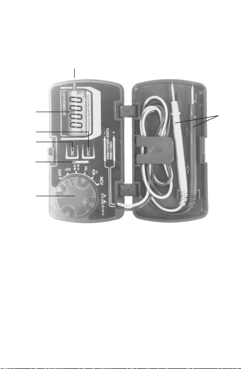
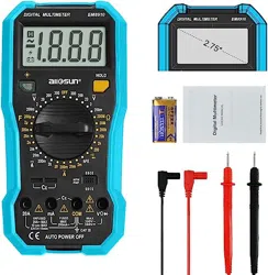
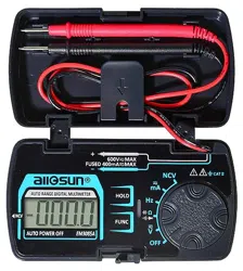
FRONT PANEL
1. Test Leads
2. NCV Sensor
An sensor used in non-contact ac voltage detection. It
is located at the mark " NCV " which is just beside the
LCD display.
3. Display
3
3
/4 digits LCD
6
Figure 1
1
3
4
5
6
7
2

4. " HOLD " key
Used to enter or exit Data Hold mode.
5. "FUNC " key
Used to switch between:
DC current and AC current measurement functions.
DC voltage and AC voltage measurement functions.
Resistance, diode, continuity and capacitance test
functions.
6. LED Indicator
This LED indicator lights when the built-in buzzer
sounds.
7. Rotary Switch
Used to select desired function as well as to turn on or
off the meter.
To save battery charge, set this switch in the " OFF "
position when the meter is not in use.
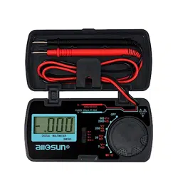
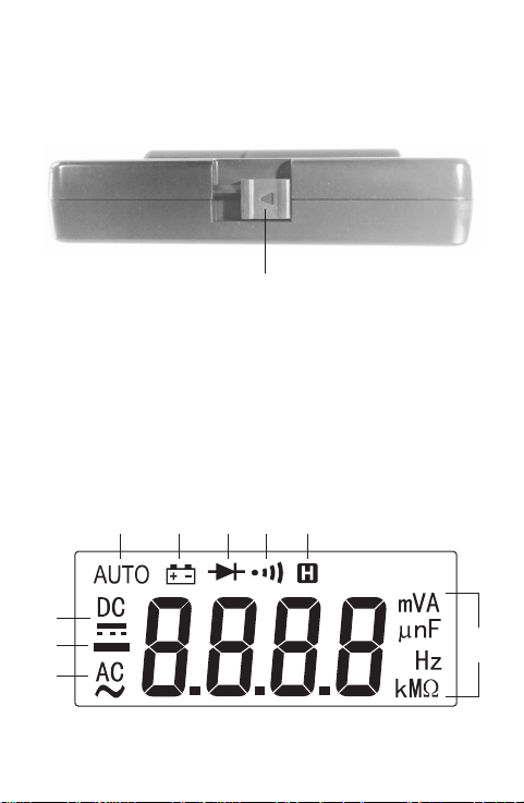
How to Fold and Unfold the Meter
See Figure 2, there is a slider lock at a side of the meter.
Before folding the meter, you must slide the slider lock in
direction of the arrow on it, to the end. Then fold the meter
and then slide the slider lock gently in the opposite
7
8
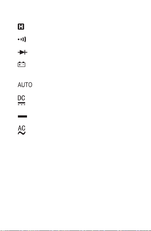
UNDERSTANDING THE DISPLAY
Figure 3
direction to lock the meter. To unfold the meter, use the
reverse procedure.
Slider Lock
( with an arrow on it )
12345
6
7
8
9
Figure 2
9
Explanations:
1.
...... The meter is in Data Hold mode.
2.
...... Continuity test function is selected.
3.
...... Diode test function is selected.
4.
...... The battery is low and must be replaced
immediately.
5.
...... Autorange mode is selected.
6.
...... DC
7.
...... Negative sign
8.
...... AC

GENERAL SPECIFICATION
Display: 3
3
/4 digits LCD
Negative Polarity Indication: Negative sign "
-
" shown
on the display automatically
9. Units
mV, V
mA
Unit of voltage
mV: Millivolt; V: Volt
1V = 10
3
mV
Unit of current
mA: Milliampere
, k ,
M
Hz, kHz,
MHz
Unit of resistance
: Ohm; k
: Kilohm; M
: Megohm
1M = 10
3
k = 10
6
Unit of capacitance
nF: Nanofarad; µF: Microfarad; mF: Millifarad
1m
F = 10
3
µ
F = 10
6
nF
Unit of frequency
Hz: Hertz; kHz: Kilohertz; MHz: Megahertz
1MHz = 10
3
kHz = 10
6
Hz
nF,
µ
F,
mF
10

11
Sampling Rate: About 3 times/sec
Low Battery Indication: "
" shown on the display
Battery: 1.5V battery, AAA or equivalent, 1 piece
Operating Environment: Temperature: 0°C to 40°C
Relative Humidity: < 75%
Temperature Coefficient:
0.2 x ( specified accuracy )/°C ( < 18°C or > 28°C )
Storage Environment: Temperature: -10°C to 50°C
Relative Humidity: < 85%
IP Degree: IP20
Operating Altitude: 0 to 2000 meters
Size: 113mm X 60mm X 25mm (for meter in folded state)
Weight: About 111g ( including battery )
SPECIFICATION
Accuracy is specified for a period of one year after
calibration and at 18°C to 28°C, with relative humidity <
75%.
Except where specified specially, accuracy is specified
from 5% of range to 100% of range.
12
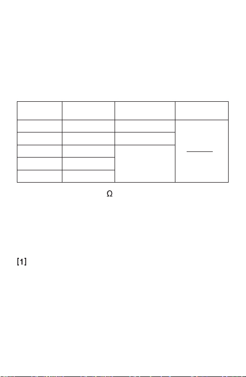
DC Voltage
400mV
4V
40V
400V
0.001V
0.01V
0.1V
0.1mV
± (0.8% + 5)
ResolutionRange Accuracy
± (0.8% + 5)
Input Impedance: 10M
Max. Allowable Input Voltage: 600V dc
Note:
When the test leads are open, the display may show a
reading other than zero. This is normal and will not affect
measurements.
When the voltage being measured is more than 600V,
the built-in buzzer will sound. When the voltage is
more than 610V, " OL " will be shown on the display.
Accuracy specifications take the form of:
±([% of Reading]+[number of Least Significant Digits])
Overrange
Indication
[
1
]
± (0.5% + 5)
600V 1V
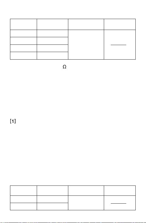
400mA 0.1mA
± (1.2% + 5)
40mA 0.01mA
DC Current
ResolutionRange Accuracy
Overrange
Indication
[
1
]
13
Input Impedance: 10M
Max. Allowable Input Voltage: 600V ac rms
Frequency Range: 40Hz to 400Hz
Response: Average, calibrated in rms of sine wave
Note:
When the test leads are open, the display may show a
reading other than zero. This is normal and will not affect
measurements.
When the voltage being measured is more than 600V,
the built-in buzzer will sound. When the voltage is
more than 610V, " OL " will be shown on the display.
AC Voltage
4V
40V
400V
0.001V
0.01V
0.1V
± (1.0% + 5)
ResolutionRange Accuracy
Overrange
Indication
[
1
]
600V 1V

14
AC Current
400mA 0.1mA
± (1.5% + 5)
40mA 0.01mA
ResolutionRange Accuracy
Overload Protection: 500mA/250V Fast fuse
Max. Allowable Input Current: 400mA
Frequency Range: 40Hz to 400Hz
Response: Average, calibrated in rms of sine wave
When the current being measured is more than
410.0mA, " OL " will be shown on the display.
Overrange
Indication
[
1
]
Overload Protection: 500mA/250V Fast fuse
Max. Allowable Input Current: 400mA
When the current being measured is more than
410.0mA, " OL " will be shown on the display.
15
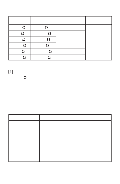
Resistance
Open Circuit Voltage: About 1V
When the resistance being measured is more than
41M , " OL " will be shown on the display.
Input Voltage: 1V rms
-
20V rms
ResolutionRange Accuracy
Frequency
± (1.0% + 5)
4.000Hz
40.00Hz
400.0Hz
40.00kHz 0.01kHz
0.001kHz
0.1Hz
0.01Hz
0.001Hz
4.000kHz
400.0kHz 0.1kHz
4.000MHz 0.001MHz
400
4k
40k
400k
0.001k
0.01k
0.1k
0.001M
± (1.5% + 5)
± (1.0% + 5)
0.1
4M
40M 0.01M
± (1.2% + 5)
ResolutionRange Accuracy
± (1.2% + 5)
Overrange
Indication
[
1
]
16
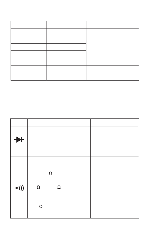
Capacitance
ResolutionRange Accuracy
4nF
400nF
0.001µF
0.1nF
0.001nF
4µF
400µF 0.1µF
40nF 0.01nF
± (5.0% + 20)
0.001mF4mF
± (3.5% + 5)
± (5.0% + 10)
40µF 0.01µF
Diode and Continuity Test
Range
Open Circuit Voltage:
about 2.1V
The built-in buzzer will sound
if the resistance is less than
about 50 .
If the resistance is between
50 and 100 , the buzzer
may or may not sound.
If the resistance is more than
100 , the buzzer won't
sound.
Remark Description
Open Circuit Voltage:
about 2.2V
The approx. forward voltage
drop of the diode will be
displayed.
17
OPERATING INSTRUCTION
Data Hold Mode
To hold the present reading on the display, press the
" HOLD " key. The meter enters Data Hold mode, and the
symbol "
" appears on the display as an indicator.
To exit the Data Hold mode, press this key again. " "
disappears.
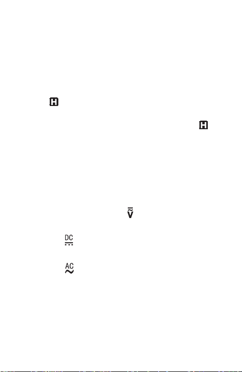
Measuring DC or AC Voltage
1. Set the rotary switch in the position.
2. If you want to measure DC voltage, press the "FUNC "
key until " " appears on the display.
If you want to measure AC voltage, press the "FUNC "
key until " " appears on the display.
3. Connect the test leads across the source or circuit to
be tested.
4. Read the reading on the display. For DC voltage
measurements, the polarity of the red lead connection
will be indicated as well.
18
Note:
To avoid electric shock to you or damage to the meter, do
not apply a voltage higher than 600V between the
terminals.
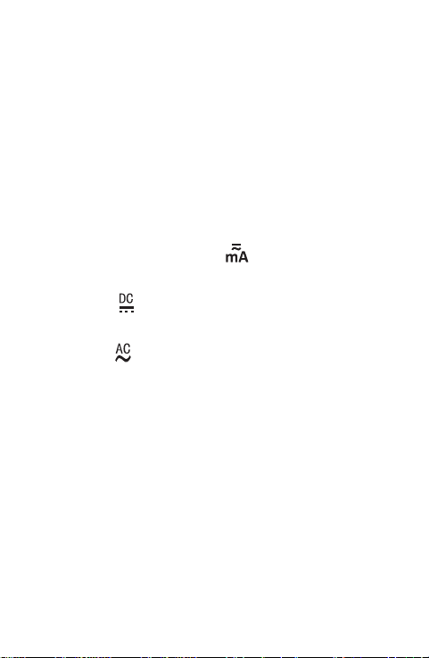
Measuring DC or AC Current
1. Set the rotary switch in the position.
2. If you want to measure DC current, press the "FUNC "
key until " " appears on the display.
If you want to measure AC current, press the "FUNC "
key until " " appears on the display.
3. Turn off power to the circuit to be tested, and then
discharge all capacitors.
4. Break the circuit path to be tested, and connect the test
leads in series with the circuit.
5. Turn on power to the circuit, then read the display. For
DC current measurements, the polarity of the red test
lead connection will be indicated as well.
19
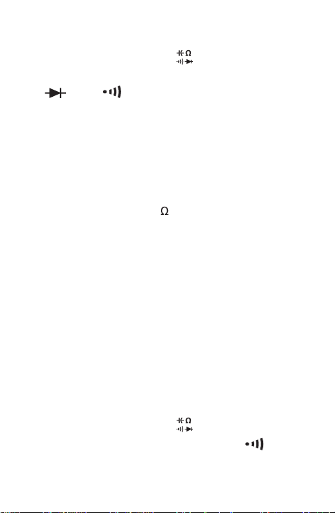
Measuring Resistance
1. Set the rotary switch in the
position.
2. Press the "FUNC " key until there are no symbols
" " and " " and capacitance measurement unit
on the display.
3. Connect the test leads across the resistor to be tested.
4. Wait until the reading is stable, then read the reading
on the display.
Note:
1. For measurements > 1M , the meter may take a few
seconds to stabilize reading. This is normal for high
resistance measurements.
2. When the test leads are open, " OL " will be displayed
as an overrange indication.
3. Before measurement, disconnect all power to the
circuit to be tested and discharge all capacitors
thoroughly.
Continuity Test
1. Set the rotary switch in the position.
2. Press the "FUNC " key until the symbol " "
appears on the display.
3. Connect the test leads across the circuit to be tested.
20
4. If the resistance is less than about 50 , the built-in
buzzer will sound.
Note:
Before test, disconnect all power to the circuit to be tested
and discharge all capacitors thoroughly.
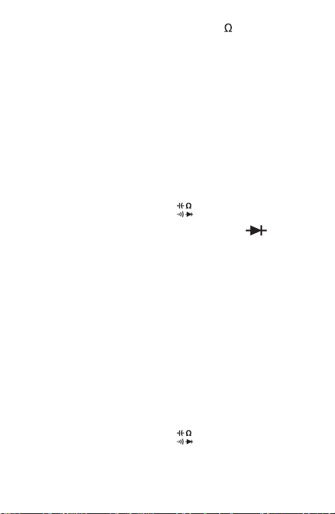
Diode Test
1. Set the rotary switch in the
position.
2. Press the "FUNC " key until the symbol " "
appears on the display.
3. Connect the red test lead to the anode of the diode to
be tested and the black test lead to the cathode of the
diode.
4. The display shows the approximate forward voltage
drop of the diode. If the connections are reversed,
" OL " will be shown on the display.
Measuring Capacitance
1. Set the rotary switch in the position.
2. Press the "FUNC " key until the display shows a
capacitance measurement unit ( nF ).

21
3. If the display shows a value other than zero, this value
must be subtracted from the subsequent
measurements to get more accurate readings.
4. Connect the test leads across the capacitor to be
tested.
5. Wait until the reading is stable, then read the reading
on the display.
Note:
1. Before measurement, make sure that the capacitor to
be tested has been discharged thoroughly.
2. For high capacitance measurements, it may take about
30 secs for the meter to complete measurement and
stabilize reading. This is normal.
Measuring Frequency
1. Set the rotary switch in the
Hz
position.
2. Connect the test leads across the source or circuit to
be tested.
3. Read the reading on the display.

22
Note:
1. The voltage of input signal should be between 1V rms
and 20V rms. The higher the frequency of input signal,
the higher the required input voltage.
2. The frequency of input signal must be more than 1Hz.
Non-Contact AC Voltage Detection
1. Set the rotary switch in NCV position. The display
shows " EF " ( refer to Figure 4 ).
2. Move the meter NCV sensor located at the " NCV "
mark just beside the LCD display ( see Figure 1 ) close
to the object to be tested. When the meter detects
electric field generated by ac voltage, the meter will
indicate the intensity of the detected electric field. The
intensity of detected electric field is indicated by the
number of the horizontal bar segments shown on the
display ( refer to Figure 5 ), the beeping rate of the
built-in buzzer, and the flashing rate of the LED
indicator. The higher the intensity of detected electric
field, the larger the number of the horizontal bar
segments displayed, and the faster the beeping rate of
the buzzer and flashing rate of the LED indicator.

23
Figure 4 Figure 5
Note:
1. Detection Range: 90V - 600V
Frequency Response: 50Hz/60Hz
2. The meter's electric field intensity indication is affected
by the magnitude of the ac voltage of the conductor
under test, the distance between the meter and the
conductor, the insulation of the conductor, and etc.
3. Because of the meter's detection limit, a line ( or
conductor) under test may be electrically live even if the
meter does not indicate presence of electric field.
4. Before use, verify the meter's operation by detecting
a known AC voltage. Do not use the meter if it
operates abnormally or malfunctions.
5. To avoid electric shock, do not touch any conductor
with hand or skin.
Automatic Power-Off
If you have not operated the meter for about 15 minutes,

24
it will turn off automatically and go into Sleep mode. To
arouse the meter from Sleep, just press a key or turn the
rotary switch.
To disable the automatic power-off feature, turn the rotary
switch from the " OFF " position to other switch setting
while holding down the "FUNC " key.
MAINTENANCE
Warning
Except replacing battery and fuse, never attempt to repair
or service the meter.
Store the meter in a dry place when not in use. Don't store
it in an environment with intense electromagnetic field.
General Maintenance
Periodically wipe the case with a damp cloth and a little
mild detergent. Do not use abrasives or solvents.
If the meter fails, check and replace ( as needed ) the fuse
25
Warning
and battery and/or review this manual to verify proper use
of the meter.
Battery and Fuse Replacement
When the low battery indicator " " appears on the
display, the battery is low and must be replaced
immediately. To replace the battery, remove the screws on
the back cover and open the back cover. Replace the
exhausted battery with a new one of the same type, make
sure that the polarity connections are correct. Reinstall the
back cover and the screws.
To avoid false readings, which could lead to possible
electric shock or personal injury, replace the battery
as soon as the low battery indicator ( ) appears.
To prevent damage, electric shock or personal injury,
use only replacement fuse specified.
Before opening the back cover or the case, turn off
the meter and remove the test leads from any circuit
under test.

26
To replace the fuse, remove the screws on the back cover
and open the back cover. Replace the blown fuse with a
new fuse of the same ratings. Reinstall the back cover and
the screws.
The meter uses one fuse:
500mA/250V fuse, Ø5X20mm
ACCESSORIES
Manual: 1 copy
NOTE
1. This manual is subject to change without notice.
2. Our company will not take the other responsibilities for
any loss.
3. The contents of this manual can not be used as the
reason to use the meter for any special application.

27
DISPOSAL OF THIS ARTICLE
Dear Customer,
If you at some point intend to dispose of this
article, then please keep in mind that many of
its components consist of valuable materials,
which can be recycled.
Please do not discharge it in the garbage bin,
but check with your local council for recycling
facilities in your area.
V191220