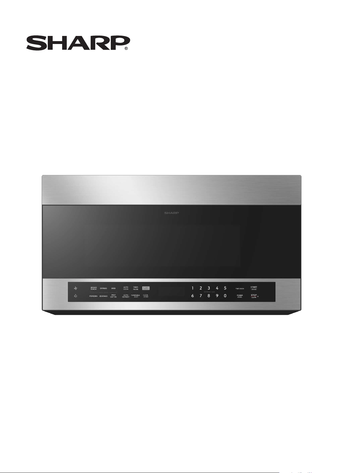
Over-the-Range Microwave Oven:
INSTALLATION MANUAL
SMO1759JS
Before You Use Your Microwave
CONTENTS
General information
Important Safety Instructions .................................. 3
Electrical Requirements .......................................... 3
Damage – Shipment/ Installation.............................. 4
Parts Included.......................................................... 4
Tools You Will Need ................................................ 5
Mounting Space ...................................................... 5
Step-by-step installation guide
6–8
Removing the Mountin g Plate ...................... 6
Finding the Wall Studs .................................. 6
Determin in g Wall Plate Location .................. 7
Aligning th e Wall Plate ................................ 8
Outside Top Exhaust
Attach Mountin g Plate to Wall............12
Preparation of Top Cabin et................13
Checking for Proper Damper
Adapting Microwave Blower
A
B
C
Installation Instructions
21
20
20
Recirculating ........................................
Mount the Microwave Oven ................19
Preparation of Top Cabin et ................17
Attach Mounting Plate to Wall ............17
Outside Back Exhaust ..........................16
Connectin g Ductwork..........................15
Adjust th e Exhaust Adaptor ................15
Operation ............................................14
Outside Back Exhaust ............................ 16–19
Adapting Microwave Blower for
Outside top Exh aust
.......... 13–14........
Placement of The Mounting Plate
......................
............................ 12–15
Preparing Rear Wall for
Remove Blower Plate ...................... 16...... ..
Charcoal Filter
Installing or Change the
23
Preparation of Top Cabin et ................2
Check Blower Plate ............................
.......................... 24
....................................22
Attach Mounting Plate to Wall ............
22
–
Installation Types............................................... 9–23
for Outside Back Exhaust................17 18
–
Mount the Microwave Oven ..........21
–
Hood Exhaust .................................................. 10 11
–
Mount the Microwave Oven ..........14 15
–
.......................... 2Template Information...................
1
EN-2
5
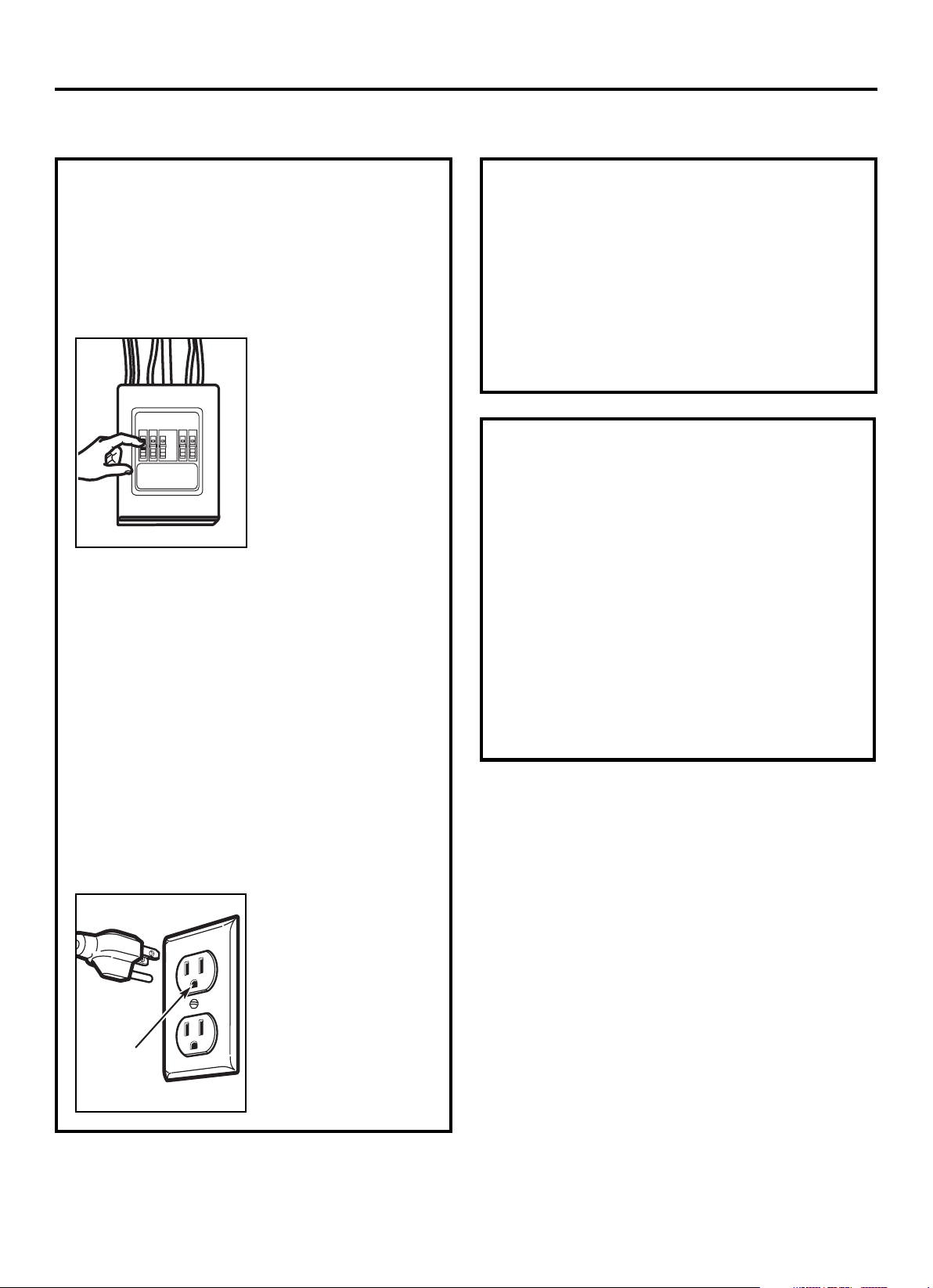
Th is product requires a three-prong grounded outlet.
Th e in staller must perform a groun d contin uity check
on th e power outlet box before begin ning th e
installation to ensure that the outlet box is properly
groun ded. If n ot properly groun ded, or if the outlet
box does not meet electrical requirements noted
(un der ELECTRICAL REQUIREMENTS), a qualified
electrician should be employed to correct any
deficiencies.
CAUTION: For personal
safety, remove house fuse
or open circuit breaker
before beginning
installation to avoid severe
or fatal shock injury.
CAUTION: For personal safety, the mounting surface
must be capable of supporting the cabinet load, in
addition to the added weight of this 63–85 pound
(28.5–38.5 kg) product, plus additional oven loads of
up to 50 pounds (22.7 kg) or a total weight of
113–135 pounds (51.3–61.2 kg).
CAUTION: For personal safety, this product cannot
be installed in cabinet arrangements such as an island or
a peninsula. It must be mounted to BOTH a top cabinet
AND a wall.
NOTE: For easier installation and personal safety, it is
recommended that two people install this product.
IMPORTANT – PLEASE READ CAREFULLY. FOR
PERSONAL SAFETY, THIS APPLIANCE MUST BE
PROPERLY GROUNDED TO AVOID SEVERE OR
FATAL SHOCK.
The power cord of this
appliance is equipped with a
three-prong (grounding)
plug which mates with a
standard three-prong
(grounding) wall receptacle
to minimize the possibility
of electric shock hazard
from this appliance.
You should have the wall receptacle and circuit checked
by a qualified electrician to make sure the receptacle is
properly grounded.
Where a standard two-prong wall receptacle is
encountered, it is very important to have it replaced
with a properly grounded three-prong wall receptacle,
installed by a qualified electrician.
DO NOT, UNDER ANY CIRCUMSTANCES, CUT,
DEFORM OR REMOVE ANY OF THE PRONGS
FROM THE POWER CORD. DO NOT USE WITH
AN EXTENSION CORD.
IMPORTANT SAFETY INSTRUCTIONS
Ensure proper
ground exists
before use
Installation Instructions
ELECTRICAL
REQUIREMENTS
Product ratin g is 120 volts AC, 60 Hertz, 15 amps and
1.6 kilowatts. Th is product must be connected to a
Th e power supply cord and plug should be brough t to a
th e prevailin g local code for this kilowatt rating.
th e requirements of th e National Electrical Code or
voltage and frequency. Wire size must conform to
seperate and dedicated supply circuit of the proper
seperate an d dedicated 20 ampere branch
Nation al Electrical Code or th e prevailin g local code.
by a qualifed electrician and con form to the
be located in the cabinet above th e microwave oven.
circuit single groun ded outlet. The outlet box should
EN-3
Th e outlet box and supply circuit should be installed
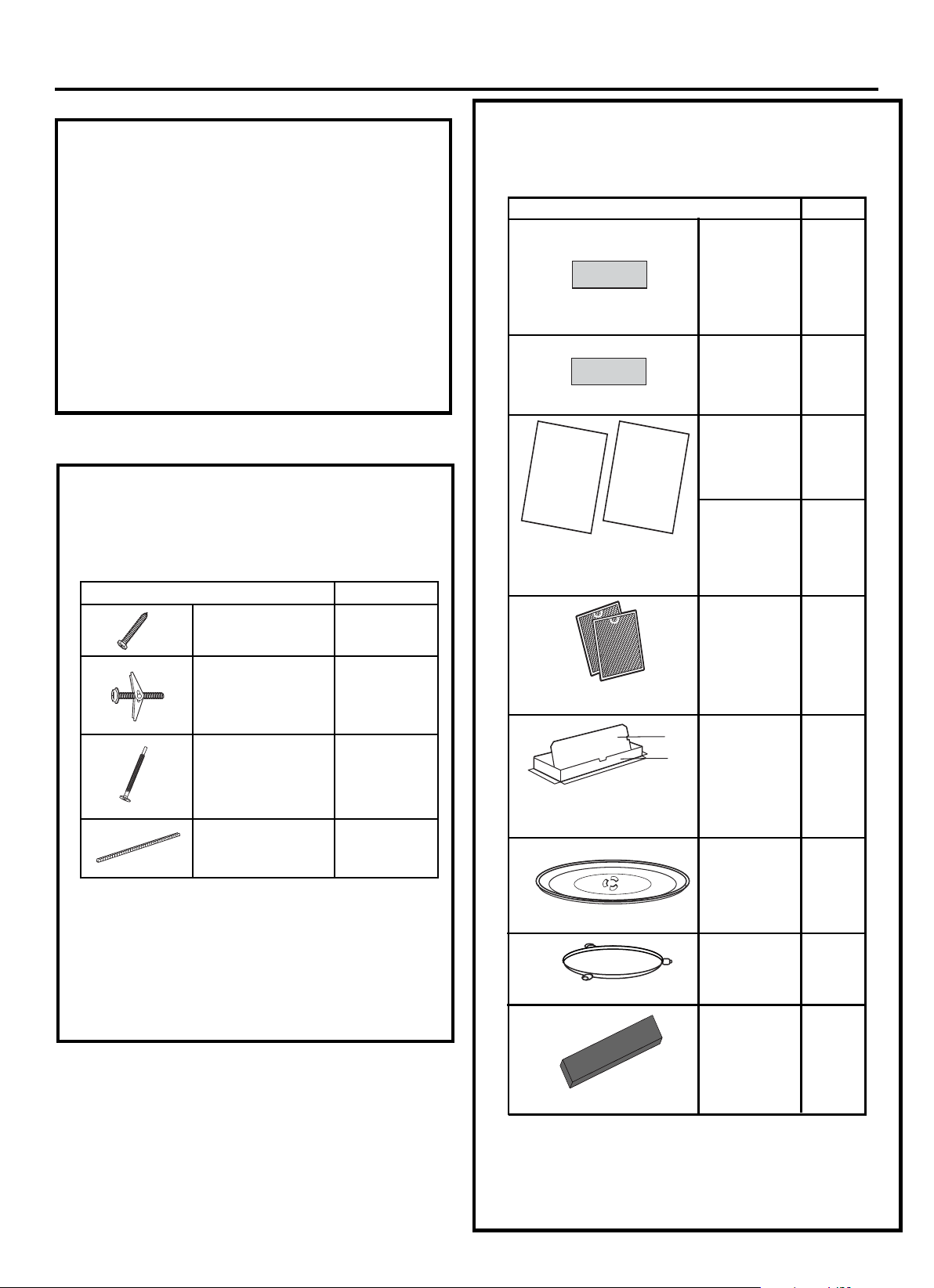
PART QUANTITY
Wood Screws 2
(
1
⁄4“ x 2“ )
Toggle Bolts (and
wing nuts) (
3
⁄16“ x 3“ )
Self-Aligning M achine 3
Screws (
1
⁄4“ -28 x 3
1
⁄4“ )
Nylon Grommet
(for metal cabinets)
1
• If the unit is damaged in shipment, return th e
unit to the store in which it was bought for repair
or replacement.
• If the unit is damaged by the customer, repair or
replacement is the responsibility of the customer.
• If the unit is damaged by the installer (if other
th an the customer) , repair or replacement must
be made by arrangement between customer
and installer.
DAMAGE—SHIPMENT
INSTALLATION
Installation Instructions
PARTS INCLUDED
You will find th e in stallation hardware con tain ed in
a packet with th e un it. Check to make sure you have
all these parts.
NOTE: Some extra parts are included.
HARDWARE PACKET
PART
QUANTITY
Template
1
Template
Installation
1
Instructions
Separately
2
Packed
Filters
PARTS INCLUDED
(CONT.)
ADDITIONAL PARTS
1
Grease
Exhaust
Glass
1
Tray
1
T ru ntable
CabinetTop
Rear
Wall
2
1
Use & Care
1
USE & CARE
MANUAL
M anual
1
EN-4
CHARCOAL
FILTER
Ring
1
2
(9KL12970000000429)
Use & Care manual : 9KL16170000A96485
9KL12270000008300
1:9KL12270000008424
2:9KL12270000003545
Adapter
9KL12270000008304
9KL12570000001005
9KL12170000004327
9KL16170000A9 40
5
2
9KL16170000A9 40
2
3
INSTALLATION
MANUAL
Installation Manual : 9KL16170000A96484
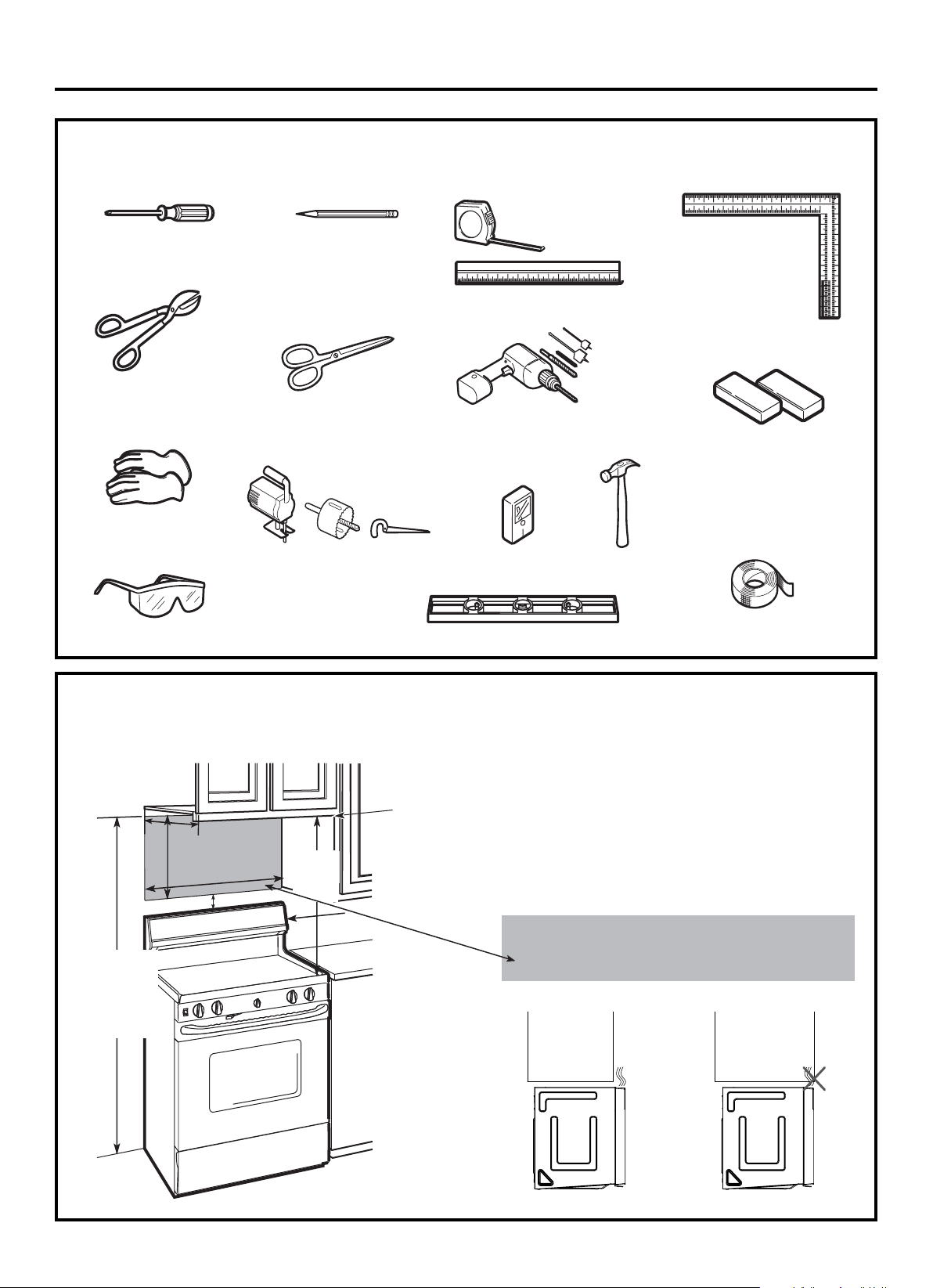
TOOLS YOU WILL NEED
Pencil
Ruler or tape measure and
straight edge
Carpenter square
(optional)
Tin snips (for cutting
damper, if required)
Electric drill with
3
⁄16“ ,
1
⁄2“ and
5
⁄8“
drill bits
Hammer (optional)
Stud finder
or
Filler blocks or scrap
wood pieces, if needed
for top cabinet spacing
(used on recessed bottom
cabinet installations only)
Gloves
Saw (saber, hole or keyhole)
Level
Duct and masking tape
Installation Instructions
Scissors
(to cut template, if necessary)
Safety goggles
MOUNTING SPACE
NOTES:
• Th e space between the cabinets must be
30
“ ( 76.2 cm) wide an d free of obstructions.
• If you are goin g to ven t your microwave oven
to th e outside, see Hood Exhaust Section for
exhaust duct preparation.
• When installing the microwave oven beneath
smooth, flat cabinets, be careful to follow the
instructions on the top cabinet template for
power cord clearance.
Bottom Edge of
Cabinet Needs to
be 30w(76.2 cm)
or M ore from the
Cooking Surface
Backsplash
69w(1.5 m)
30
“ (76.2 cm)
2
“ (5.1 cm)
30
“
(76.2 cm)
min.
16
1
⁄2
“
(41.9 cm)
13 Maximum (33 cm)
“
As a guide to installation, see page 25 for Mo un ting
Template In formation.
•
•
If the cabinet depth including th e cabinet doors
is more th n 13'""' th n th e unit must be spaced
out from wall using adequate materials supportin g
150 Ibs to allow proper top vent air exhaust/ intake.
a e
EN-5
# Phillips screw driver
2
the M icrow ave
to the topof
f rom the f loor
or more
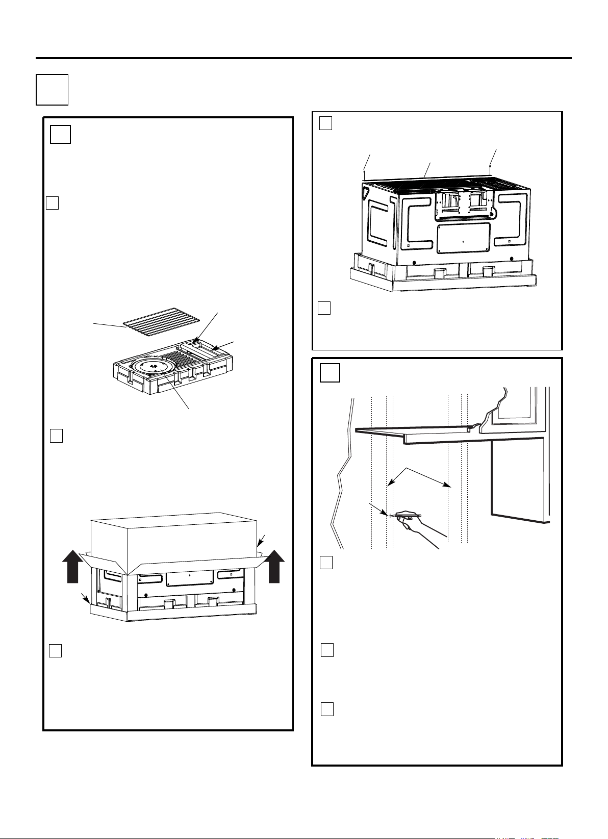
PLACEMENT OF THE M OUNTING PLATE
1
Installation Instructions
Find th e studs, using one of th e followin g
methods:
A. Stud finder – a magnetic device which
locates n ails.
B. Use a hammer to tap ligh tly across th e
mountin g sur face to find a solid soun d.
Th is will indicate a stud location .
After locating th e stud(s) , find th e center by
probing th e wall with a small nail to find th e edges
of th e stud. Then place a mark halfway between
the edges. The center of any adjacent studs should
be 16w(40.6 cm) or 24w( 61 cm) from th is mark.
Draw a line down th e center of th e studs.
THE MICRO WAVE MUST BE CO NNECTED TO
AT LEAST O NE WALL STUD.
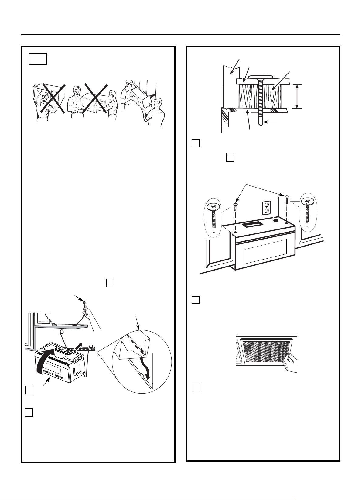
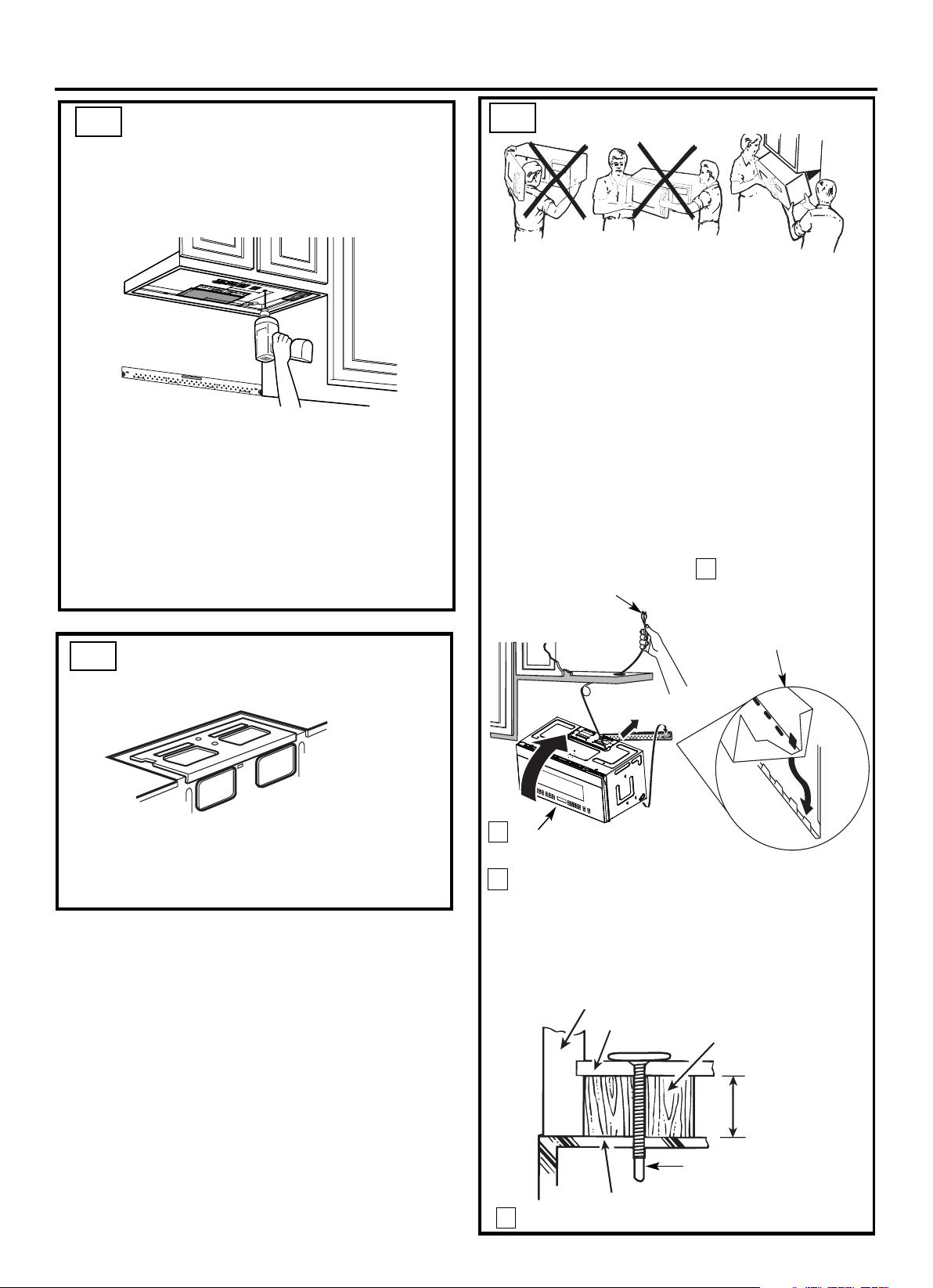
1
Fold back all 4 carton flaps fully against carton
sides. Then carefully roll the oven and carton over
onto the top side. Th e oven should be resting in
the Styrofoam.
REMOVING THE MICROWAVE
OVEN FROM THE CARTON/
REMOVING THE MOUNTING
PLATE
FINDING THE WALL STUDS
B
.
A
.
2
Wall
Studs
Center
3
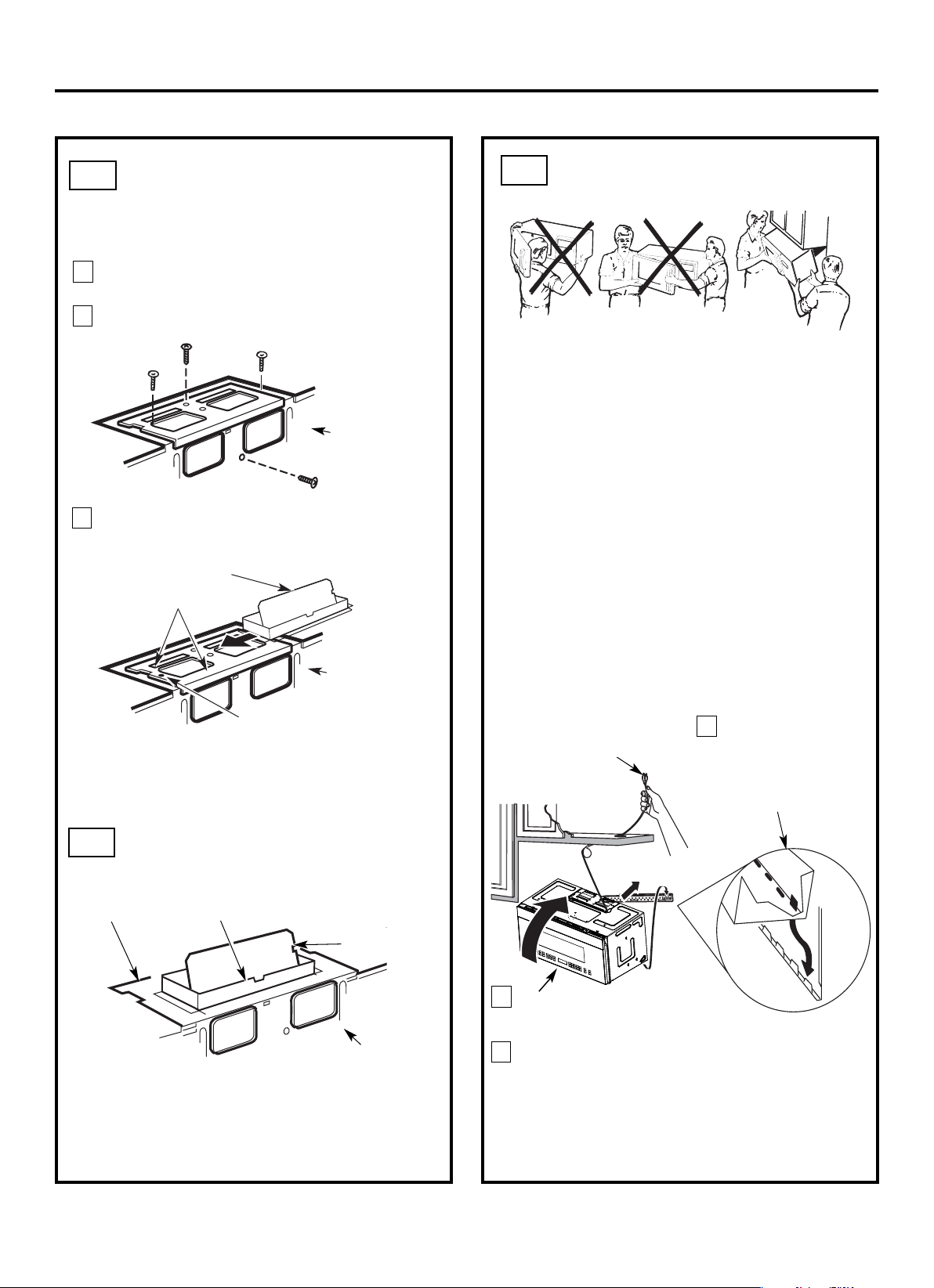
Pull the carton up and off th e oven .
2
3
5
4
Cut the middle of the outer protective plastic bag to
r
emove
the
ounting late
m
p
Remove the screws from each end of th e mountin g
plate. This plate will be used as the rear wall template
an d for moun ting. Reinstall the screws into the holes
where they were removed.
EN-6
1
Exhaust Adapter
Filters and Turntable Ring below glass tray
Small Hardware Bag
Shelf (For
some models)
Remove the top cover board, installation
instructions, use and care, exhaust adapter,
turntable ring, shelf, filters, glass tray and the
Do not remove the
Styrofoam protecting the front of the oven.
ba
g.
small hardware
Carton
Styrofoam
Screws
Screws
Mounting Plate
DETERMINING WALL PLATE LOCATION UNDER YOUR CABINET
C.
Installation Instructions
Plate position flat bottom
cabinet
Draw a line on the
back wall equal to the
depth of the front
overhang.
to Cooktop
C
3/
8"
TO
EDGE
NOTE:
IT IS VERY IMPORTANT TO
R
E
AD
A
ND
FO
LLOW
T
H
E
DIRECT
ION
S
IN TH
E
INST
A
LL
ATION
INSTRUC
TIO
N
S
B
E
F
ORE PR
OCEEDING WIT
H T
HIS
RE
A
R W
ALL TE
MP
L
ATE.
This Re
a
r W
all
Templat
e
serves
to pos
ition
t
he
bo
tto
m
m
o
u
nti
ng plate
and
t
o lo
cate the
ho
ri
zo
nt
al
e
x
haust
o
u
tlet.
1. Use
a
lev
el
t
o
check t
h
a
t
the
t
emp
late
is p
o
s
it
ione
d
a
c
c
u
ra
t
e
ly.
2
.
Locate an
d
m
ar
k at lea
s
t
one stud
o
n t
h
e
le
ft or
right
s
ide o
f t
h
e
c
e
nterline.
It
is
impo
rt
ant
t
o use at
l
east
o
ne woo
d
s
c
re
w
mou
n
ted
f
ir
mly
in
a
stud to su
p
po
rt
the w
e
ight
of the
micr
owa
v
e. Mark t
w
o ad
d
iti
onal,
e
ve
nly
spac
e
d
location
s
for
th
e
s
upplied
t
o
gg
le
bo
lt
s.
3
.
D
rill
hole
s
in
the marke
d
lo
c
ation
s
.
Whe
re
there
is
a
stud, dr
ill
a 3/1
6
" hole fo
r
w
ood scre
ws
.
For
hole
s
that
do n
ot
li
ne up wit
h
a st
ud
, d
rill 5/8"
hole
s
for
togg
le
bo
lt
s.
D
O
N
OT I
NS
TALL
T
HE MOU
N
T
IN
G
P
L
A
TE
AT
TH
IS
TIME.
4.
R
e
m
o
ve the tem
p
late
f
rom t
h
e
r
e
ar w
al
l.
5.
Rev
i
e
w t
he Inst
a
lla
tion Inst
r
u
ct
ion
bo
o
k f
o
r
your
installat
ion
sit
u
at
io
n
.
L
oc
a
te an
d
ma
rk
h
o
l
es
to ali
g
n with ho
l
e
s
i
n the
mo
u
n
t
ing
p
l
a
te.
IMP
ORT
ANT
:
LOCATE
A
T
LEAS
T
ONE
S
TU
D ON EITH
ER
S
IDE
O
F
T
HE CENTE
R
LIN
E.
MA
RK TH
E
LOCATI
ON FOR
2
AD
D
ITIO
NA
L, E
VE
NLY
S
P
AC
E
D TOGG
LE BOL
TS IN
THE MO
UN
T
IN
G P
L
AT
E
A
RE
A
.
Locate a
nd
ma
rk hol
e
s to
a
lign with holes in th
e
mo
unting pl
a
te.
IMPO
RTA
N
T:
LOCA
TE AT
L
E
AST
ONE ST
U
D ON EITH
E
R SIDE
O
F
T
H
E
C
ENT
E
RLIN
E.
MARK
THE LOC
ATION F
OR
2 AD
DIT
IONAL, E
V
E
N
L
Y
SPACE
D TOGG
L
E BOLTS IN
T
H
E MO
U
NT
IN
G
P
LATE
AR
E
A.
T
r
im
th
e rear w
all
te
m
p
late
along the do
tte
d line.
Trim th
e r
ear
wa
ll
te
m
p
l
a
te
alo
n
g th
e
d
o
tte
d
line
.
12"
4
"
D
a
rle
vue
lt
a
a la h
o
ja
p
a
ra
c
ons
u
l
t
ar
la
versión en
E
spa
ño
l.
3/8
"
TO EDGE
N
O
TE
: I
T
IS
VERY
IMPORTAN
T T
O
READ AND FO
LLOW THE D
IREC
TIONS
I
N
TH
E
INST
ALLATION
INST
R
U
C
TI
O
N
S
BEFO
RE PROC
EEDING
W
ITH TH
I
S
R
EAR WALL
T
EMPL
ATE.
This
R
ear W
all Templa
t
e serves
to p
ositio
n
the bot
to
m
mou
ntin
g p
la
te
and to locat
e
the ho
rizontal e
xhaust
outle
t.
1.
Us
e a
lev
el to
c
he
ck
th
at the template is
po
sitio
n
ed
accurate
ly.
2
. Locate and mark a
t le
as
t
one stud
on
t
he left
or
r
ig
ht s
id
e
o
f
the ce
nter
l
ine.
It is
i
mportant to
use at leas
t
one
wo
od
s
cr
e
w
mounted firmly in
a
stud
to suppor
t the w
e
ight
of th
e microw
a
ve.
Ma
rk
two
a
d
ditional,
evenly sp
aced
locations for th
e
s
uppli
e
d tog
gle
bo
lts.
3.
Drill holes
in
th
e marked lo
c
ations
.
Where th
e
re is
a stud, drill a 3/16" hole fo
r w
ood screws. For
ho
le
s
that do no
t lin
e u
p
with a stud,
drill 5
/8" hole
s fo
r
tog
gle b
olts.
DO
NOT
IN
STAL
L
TH
E
MO
U
NTING
PL
ATE
AT TH
IS TIME.
4. Remov
e
the template
fr
om the rear wall.
5. Review
the Insta
ll
ation
Instruc
tion boo
k for your
in
stallatio
n
s
ituation.
Lo
cate an
d
ma
rk h
ol
es t
o align with holes in t
h
e
mounting pla
t
e
.
I
M
PORT
ANT
:
LOC
ATE AT
LEAST
ONE STU
D
ON
EI
THER SI
D
E OF
TH
E CENTER
LINE.
MAR
K T
H
E LOCATIO
N
FOR
2
AD
DI
T
IONAL, EVEN
L
Y
SPACED TOG
GLE BO
L
T
S I
N TH
E MOUNTIN
G
PLATE
AR
EA.
Locate
and
ma
rk
hol
es to align with
h
oles
in t
h
e
mounting plat
e.
IMPO
R
TANT:
LOC
ATE AT
LEAST ON
E ST
U
D ON EI
T
HER SIDE OF
TH
E
CEN
TERLINE
.
MARK T
HE LOC
ATION FOR 2 AD
D
ITION
AL
, EVENLY
SPA
C
ED
TOGGLE BO
L
T
S I
N
TH
E MO
UN
TI
NG PLAT
E
AR
EA.
Trim
th
e re
ar
wall
template along the d
otted
line.
Trim
the
r
ear wall
templ
ate
a
l
ong
th
e dotted
line.
12
"
4"
Darle
vu
el
t
a
a
la ho
ja
para
co
n
s
u
lta
r
la
v
ersió
n en Esp
añol.
²
A
t
l
e
a
s
t
3
0
″
C
3/8" T
O
EDGE
N
O
T
E: I
T IS VERY IMPORTANT TO
R
EAD
AND
FOLLOW
THE DIREC
T
IONS
I
N THE I
NSTALL
ATION
INSTRU
C
TIONS
BEF
ORE PROC
EED
I
N
G
W
ITH
THIS
R
E
AR
WALL TEMPLAT
E.
Th
is
Rea
r Wall Te
mp
late serves to positio
n the bo
tto
m
mounting pla
te and to lo
ca
te th
e h
o
rizontal exhaust
o
u
tlet.
1. Use
a leve
l to che
ck t
h
at the temp
late is positioned
a
ccu
rately.
2.
Loca
te and mark at least on
e stu
d on the le
ft o
r
righ
t sid
e
of th
e centerline.
It is importa
n
t
to use at
least one woo
d
scre
w
mounted
firmly in
a stu
d to suppo
rt the weigh
t
o
f
t
he microwave. Mark two additional, evenly
sp
aced
locatio
n
s for th
e
supplied
toggle bolts.
3
.
D
rill
holes in the m
a
r
ked location
s. Where
there
is
a stud, drill a 3/16" h
ole for wo
od screws. For h
oles
th
at do not lin
e
u
p
with a stu
d
, drill 5/8" hole
s fo
r
toggl
e bolt
s.
DO NOT
INSTA
LL
THE MOU
NTING P
LA
TE
AT TH
IS
TIME.
4
.
Remo
ve the temp
late
from the
re
a
r wall.
5. Review the I
nstallation In
struction
book for you
r
i
nstallation situation.
Lo
cate and mar
k
h
oles
to
ali
gn
w
ith
ho
les
in the
m
o
unting
plate.
I
M
POR
TANT:
LOC
AT
E
A
T LEA
ST
ON
E ST
UD ON
E
IT
HER
SIDE OF
TH
E CE
N
TERLINE.
M
A
R
K
THE LOCAT
ION
FOR
2 ADDI
TIO
N
AL, EVENLY
SPACED TOGGL
E BOLT
S IN THE
M
OUN
TING PLAT
E
AREA.
Loc
at
e
a
nd m
ark holes
t
o
align wit
h holes in t
he
mou
nt
i
ng
plat
e
.
I
MPOR
TANT:
LOCATE AT LEAST ON
E STUD
ON EITH
ER
SI
D
E OF
THE CENTERLIN
E
.
MAR
K
TH
E LOCATION F
OR
2
ADDI
TIONAL, E
VENLY
SPA
C
ED
TOGGLE BOLTS
IN THE MOUNTING
PLATE
AREA.
T
rim the rear
wall
te
m
pl
ate
al
on
g
th
e
dotted li
n
e.
T
rim the rear
wal
l
templ
at
e al
ong
th
e dotted li
ne.
12"
4
"
Da
rle vuelta a la
hoja para
c
ons
ultar la
v
ersión
en
Esp
añol.
Your cabinets may have decorative trim that
interferes with the microwave installation. Remove
the decorative trim to install the microwave properly
and to make it level.
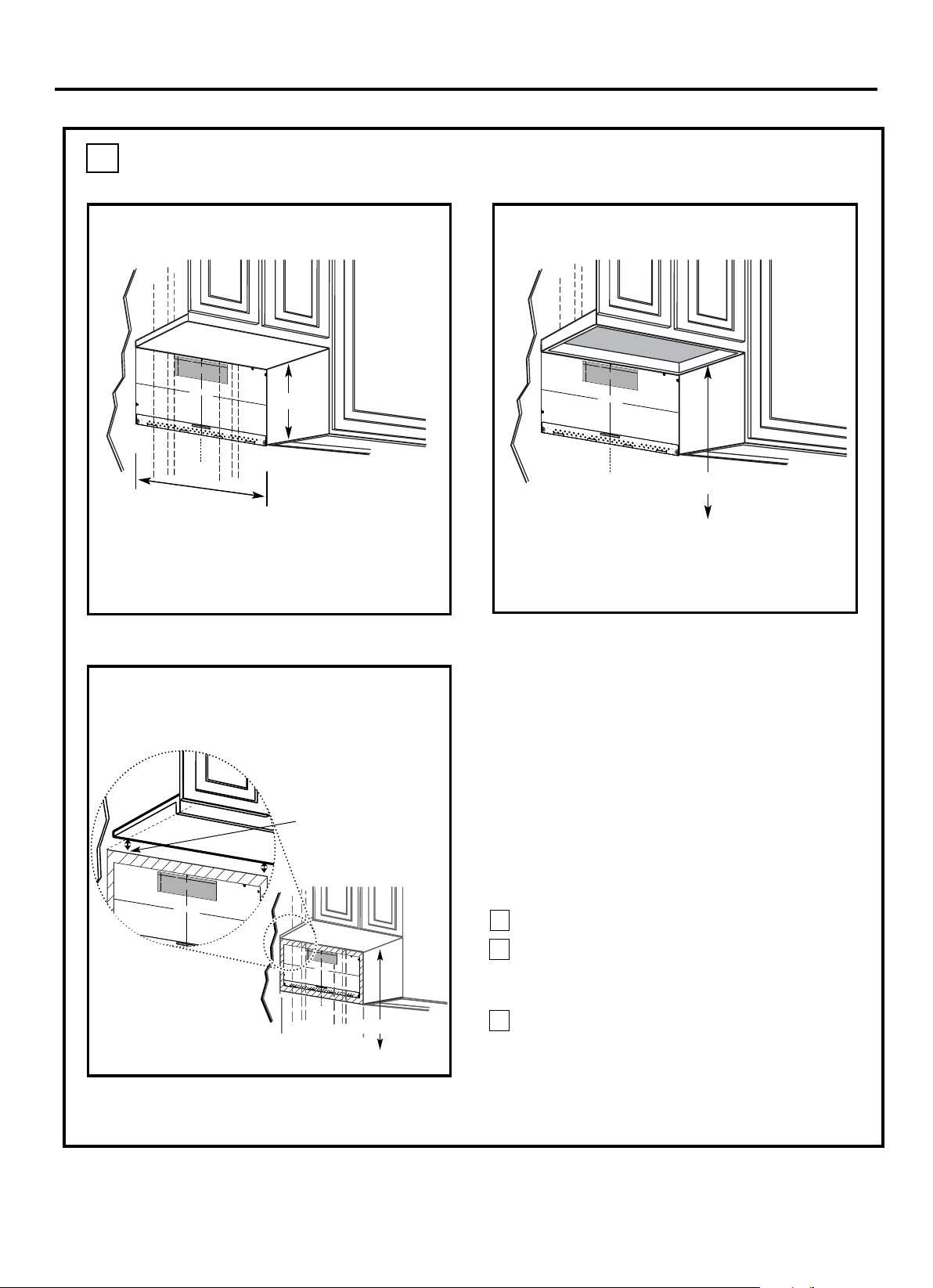
THE M ICROWAVE MUST BE LEVEL.
Use a level to make sure the cabinet bottom is level.
If the cabinets have a front overhang only, with no
back or side frame, install the mounting plate down
the same distance as the front overhang depth. This
will keep the microwave level.
Measure the inside depth of the front overhang.
Draw a horizontal line on the back wall an equal
distance below the cabinet bottom as the inside
depth of the front overhang.
For this type of installation with front overhang
line, not touching the cabinet bottom as described
in Step D.
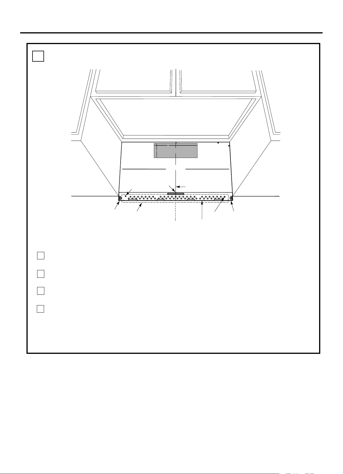
Draw a vertical line on
the wall at the center of
the 30
″ wide space.
Tape the Rear Wall
Template onto the wall
matching the centerline
and touching the
bottom of the cabinet.
to Cooktop
Draw a vertical line on the wall at the center of the
30
″ space.
Tape the Rear Wall Template onto the wall
matching the centerline and touching the bottom
C
3/8
"
TO
E
D
GE
NOTE:
IT IS
VERY
IMPORTANT TO
RE
A
D
A
ND FO
LLOW T
HE DIRECT
IONS
IN THE INSTALLA
TION I
NS
TRUCT
I
ONS
BE
F
OR
E PR
OCEEDING
WI
T
H T
HIS
RE
AR WA
LL TEMP
LATE
.
This Rear
Wa
l
l
Temp
l
ate
serve
s to
p
o
si
t
ion the
b
ottom
mo
un
t
in
g p
late an
d to locate the
h
o
r
i
z
on
tal
e
xhaust
outl
e
t
.
1. Use a
le
vel
to che
ck t
hat
the
template is position
ed
accur
ate
ly.
2.
Locate and ma
r
k
at least one stu
d on the
l
e
ft
or
r
i
ght s
i
de o
f the
cente
r
line.
It
i
s important t
o use
at least one
wood
sc
r
ew mo
u
nt
ed
fi
rml
y in
a
stud t
o su
pport the weight
of the m
icrow
ave. Mark
tw
o a
dditional
,
e
ve
nl
y spa
ce
d
lo
cations for the su
pplied
tog
gl
e bolts.
3. Drill holes in the
m
arked
l
ocation
s. Wh
ere there is
a
stud, drill a 3/16"
hole for
wood scr
ew
s.
For hol
es
that
do
n
o
t line
up wit
h
a st
u
d, dri
ll 5/8" h
ole
s f
o
r
t
o
g
gle b
olts
.
DO
NOT
INSTALL THE MOUNTING
PLATE
AT TH
IS T
IME.
4.
R
em
o
ve the
template
fr
o
m t
h
e rear wall.
5. Revie
w the
Installa
tio
n
Instruction
b
ook f
o
r your
i
n
sta
ll
ation si
tuation.
Locate and
mark
holes
to
ali
gn with
holes
in the
mounti
ng
plate.
I
MPO
RT
ANT:
LOCA
TE AT LEAST ONE
S
TUD
ON EIT
HER S
IDE
OF
THE
CENT
ERLINE.
MARK
THE LOC
A
T
IO
N
FO
R
2
ADDITI
ONA
L, E
VE
NLY
SP
A
CE
D
TOGGLE
BOLTS
I
N THE
MOUNTING PLATE
A
R
EA.
Loc
ate and mark h
ol
es
t
o a
l
i
gn
with
holes in the
moun
t
i
ng pl
at
e.
IMPO
RTANT
:
LOCA
T
E
AT LEA
ST ONE
STUD ON
EITHE
R
S
IDE OF
THE CE
NT
ERL
I
NE.
MA
RK T
HE
LOC
AT
ION
FO
R
2
ADDI
T
IONAL, E
VENL
Y
S
PA
CED T
O
GGLE
B
OLTS IN THE
MOUNT
ING PLA
T
E
A
REA.
Trim
the
rear
wall template
al
on
g the dotted lin
e.
T
rim the rear w
all temp
l
ate
al
ong t
he dott
ed
lin
e.
12"
4"
Darle vuelta a la
hoja
para
co
n
s
ultar la
versión
en
E
s
p
año
l.
cabinet bottom
with front overhang
Plate position framed
recessed
Plate position
bottom
1
3
2
300″0
30
cabinet frame.
300″0
30
2″
16-1/2
-beneath
-beneath
-beneath recessed
cabinet
EN-7
only, align the rear template with this horizontal
Installation Instructions
ALIGNING THE WALL PLATE
D.
CAUTIO N: Wear gloves
to avoid cutting fingers on
sh arp edges.
Hole A
Hole B
Centerline
notches
Draw a Vertical Line
on Wall from Center
of Top Cabinet
Draw a horizontal line on wall at the
bottom of “Rear Wall Template”.
Horizontal Line
Horizontal Line
C
3/8" TO EDGE
%#76+10Ä+(':*#756#ਸ਼+5
215+6+10'&
1765+&'
4'%1//'0&'&&+/'05+
10)4'#5'Ä.#&'0#+49+..
&+5%*#4)'+061*175'5647%674'
/+0+/7/9+&6*4'37+4'&
4'#49#..6'/2.#6'
NOTE: IT IS VERY IMPORTANT TO
READ AND FOLLOW THE DI
RECTIONS
IN THE INSTALLATION INSTRUCTIONS
BEFORE PROCEEDI
NG WITH
THIS
REAR WALL TEMPLATE.
This Rear Wal
l Template serves t
o position the bottom
mounting plate and to locate
the horizontal exhaust
outlet.
1. Use a level to check th
at the template is positioned
accurately.
2. Locate and ma
rk at least one stud on the left or
right side of the centerlin
e.
016'
It is important to use at least one wood
screw mounted firmly in a stud to s
upport the weight
of the microwave. Mark two add
itional, evenly spaced
locations for the supp
lied toggle bolts.
3. Drill holes in the marked locatio
ns. Where there is
a stud, drill a 3/16" hole for
wood screws. For hole
s
that do not line up with a st
ud, drill 5/8" holes for
toggle bolts.
016'
DO NOT INSTALL THE M
OUNTING PLATE
AT THIS TIME.
4. Remove the tem
plate from the rear wall.
5. Review the Installation Instru
ction book for your
installation situation.
Locate and mark
holes to align with h
oles in the
mounting plat
e.
IMPORTANT:
LOCATE
AT LEAST ONE
STUD ON EITHER SIDE OF
THE CENTERLINE.
MARK THE LOCATION FOR 2
ADDITIONAL, EVENLY
SPACED
TOGGLE BOLTS IN
THE MOUNTING PLATE
AREA.
Locate and mark
holes to align with hol
es in the
mounting plat
e.
IMPORTANT:
LOCATE
AT LEAST ONE
STUD ON EITHER SIDE OF
THE CENTERLINE.
MARK THE LOCATION FOR 2
ADDITIONAL, EVENLY
SPACED
TOGGLE BOLTS IN
THE MOUNTING PLATE
AREA.
Trim the rear
wall template al
ong the dotted
line.
%
#
$
%
&
(%76176(14*14+<106#.
1765+&'':*#756
%76*1.'6*417)*
4'#49#..
(14':*#756#ਸ਼
12"
4"
Darle vuelta a la hoja para consultar la
versión en Español.
Draw a vertical line on the wall at the center of the
30" wide space.
NOTE: DO NOT M OUNT THE PLATE AT THIS
TIME.
NOTE:
important to have at least one wood screw mounted
firmly in a stud to support the weight of the
microwave. Set the mounting plate aside.
1
2
Draw a horizontal line on the wall at the bottom of
“Rear Wall Template”.
3
Refer to section 1B. Finding the wall studs.
For attaching the mounting plate into stud drill
a 3/16" hole into wood stud. Drill a 5/8" hole for
4
EN-8
Area D
Find a wall stud in area "D" of mounting plate
toggle bolt in 2 other locations at or as close to
both hole A and B as possible.
n rea D, C and draw a circle to line up with the stud. It is
If Holes A and B are not in a stud, find a stud somewhere
For proper installation, holes A and B should be
used.
i a

A
INSTALLATION TYPES
Th is microwave oven is design ed for adaptation to
the following three types of ventilation:
A. Outside Top Exhaust (Vertical Duct)
B. O utside Back Exhaust (H orizontal Duct)
C. Recirculating (Non-Vented Ductless)
proceed to that section .
OUTSIDE TOP EXHAUST
(VERTICAL DUCT)
OUTSIDE BACK EXHAUST
(HORIZONTAL DUCT)
RECIRCULATING
(NON-VENTED DUCTLESS)
See page 12
recirculatin g exhaust.
disposable charcoal filter
installed to h elp r em ove
smoke and odors.
Adaptor in Place for
Outside Top Exhaust
2
B
C
Adaptor M ust Be
M oved to the Back for
Outside Back Exhaust
NOTE: This microwave is shipped assembled for
Recirculating. Select the
type of ventilation required
(Choose A, B or C)
for your in stallation and
See page 16
See page 20
Models ar e shipped for
Installation Instructions
NOTE: Read the next two pages only if you plan to vent your exhaust to the
outside. If you plan to recirculate the air back into the room, proceed to page 20.
EN-9
Th ese mod els h ave a

EQUIVALENT NUM BER EQUIVALENT
DUCT PIECES LENGTH x USED = LENGTH
Rectangular-to-Round 5 Ft. (1.5 m) x ( ) = Ft. or m
Transition Adaptor*
Wall Cap 40 Ft. (12.2 m) x ( ) = Ft. or m
90° Elbow 10 Ft. (3 m) x ( ) = Ft. or m
45° Elbow 5 Ft. (1.5 m) x ( ) = Ft. or m
90° Elbow 25 Ft. (7.6 m) x ( ) = Ft. or m
45° Elbow 5 Ft. (1.5 m) x ( ) = Ft. or m
Roof Cap 24 Ft. (7.3 m) x ( ) = Ft. or m
Straight Duct 6“ (15.2 cm) 1 Ft. (0.3 m) x ( ) = Ft. or m
Round or 3
1
⁄4“ x 10“
(8.2 x 25.4 cm Rectangular)
Total Ductw ork = Ft. or m
Equivalen t length s of duct pieces are based on actual tests
and reflect requirements for good venting per forman ce with
any vent h ood.
* IMPORTANT: If a rectan gular-to-round transition
adaptor is used, the bottom corners of th e damper
will have to be cut to fit, using the tin sn ips, in order
to allow free movemen t of th e damper
.
NOTE: If you n eed to install ducts, note that th e total
duct length of 3
1
⁄4” x 10” (8.2 x 25.4 cm) rectangular or
” ( 15.2 cm) diameter round duct
Outside ventilation requires an EXTERNAL EXHAUST
NOTE: It is importan t th at venting be installed using
th e most direct route an d with as few elbows as possible.
Th is ensures clear ven ting of exh aust and h elps preven t
blockages. Also, make sure dampers swing freely and
nothing is blocking the ducts.
Exhaust connection:
Th e exh aust adaptor has been designed to mate with
a standard 3
1
⁄4” x 10” (8.2 x 25.4 cm) rectangular duct.
If a round duct is required, a rectangular-to-roun d
Maximum duct length:
For satisfactory air movement, th e total duct length of
3
1
⁄4” x 10” (8.2 x 25.4 cm) rectangular or
6 ” ( 15.2 cm)
diameter round duct should not
exceed 120 equivalent
feet (36.5 m).
Elbows, transitions, wall and roof caps,
etc.,
present addition al resistance to airflow and are
equivalent to a section of straight duct which is longer
th an their actual ph ysical size. When calculating the total
duct length, add the equivalent lengths of all tran sitions
and adaptors plus th e length of all straight duct sections.
Th e chart below shows you how to calculate total
equivalent ductwork length using the approximate feet
of equivalen t length of some typical ducts.
Installation Instructions
INSTALLATION INSTRUCTIONS FOR EXTERNAL EXHAUST DUCTING
DUCT.Read th e followin g carefully.
(12.5”
should not exceed 120 equivalent feet (36.5 m).
diameter/ 6
(12.5”
diameter/
7 cm)
7 cm)
tran sition adaptor must be used.
diameter duct is acceptable to use.
"
A 5"""''''' " (12.7cm)/ 6" (15.2cm)
"
EN-10

EQUIVALENT NUM BER EQUIVALENT
DUCT PIECES LENGTH x USED = LENGTH
Roof Cap 24 Ft. (7.3 m) x (1) = 24 Ft. (7.3 m)
12 Ft. (3.6 m) Straight Duct 12 Ft. (3.6 m) x (1) = 12 Ft. (3.6 m)
(6” /15.2 cm Round)
Rectangular-to-Round 5 Ft. (1.5 m) x (1) = 5 Ft. (1.5 m)
Transition Adaptor*
Equivalent lengths of duct pieces are based on actual tests and
reflect requirements for good venting performance with any vent hood.
Total Length = 41 Ft. (12.4 m)
Th e followin g chart describes an example of one possible
ductwork installation.
OUTSIDE TOP EXHAUST (EXAMPLE ONLY)
NOTE: For back exhaust, care should be taken to align exh aust with space between studs, or wall should be prepared
at th e time it is constructed by leaving enough space between the wall studs to accommodate exh aust.
* IMPORTANT: If a rectan gular-to-round transition adaptor is used, th e bottom corners of the damper
will have to be cut to fit, using the tin snips, in order to allow free movement of the damper.
Th e followin g chart describes an example of one possible
ductwork installation.
Installation Instructions
OUTSIDE BACK EXHAUST (EXAMPLE ONLY)
EQUIVALENT NUM BER EQUIVALENT
DUCT PIECES LENGTH* x USED = LENGTH
Wall Cap 40 Ft. (12.2 m) x (1) = 40 Ft. (12.2 m)
3 Ft. Straight Duct 3 Ft. (0.9 m) x (1) = 3 Ft. (0.9 m)
(3
1
⁄4” x 10” / 8.2 x 25.4 cm
Rectangular)
90° Elbow 10 Ft. (3 m) x (2) = 20 Ft. (6 m)
Equivalent lengths of duct pieces are based on actual tests and
reflect requirements for good venting performance with any vent hood.
Total Length = 63 Ft. (19.1 m)
EXTERNAL EXHAUST DUCTING
EN-11
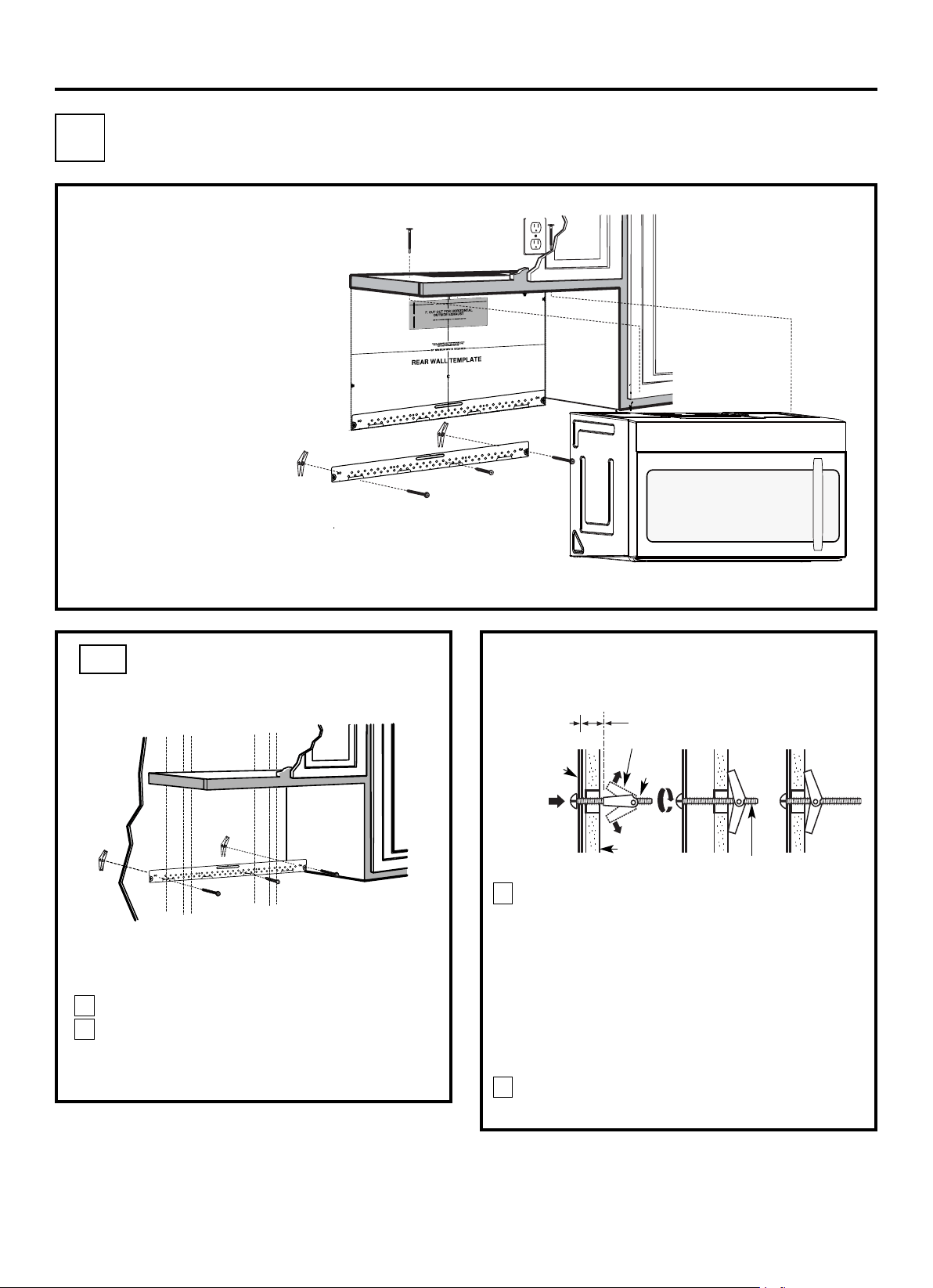
Place the mounting plate against th e wall and
insert the toggle wings into the h oles in the wall
to mount the plate.
NOTE: Before tightening toggle bolts and wood
screw, make sure the bottom of th e mounting plate
centered un der the cabin et.
CAUTION: Be careful to avoid pinching fingers
between th e back of the moun ting plate and th e wall.
to h elp tigh ten the bolts.
3
4
ATTACH THE MOUNTING
PLATE TO THE WALL
A1.
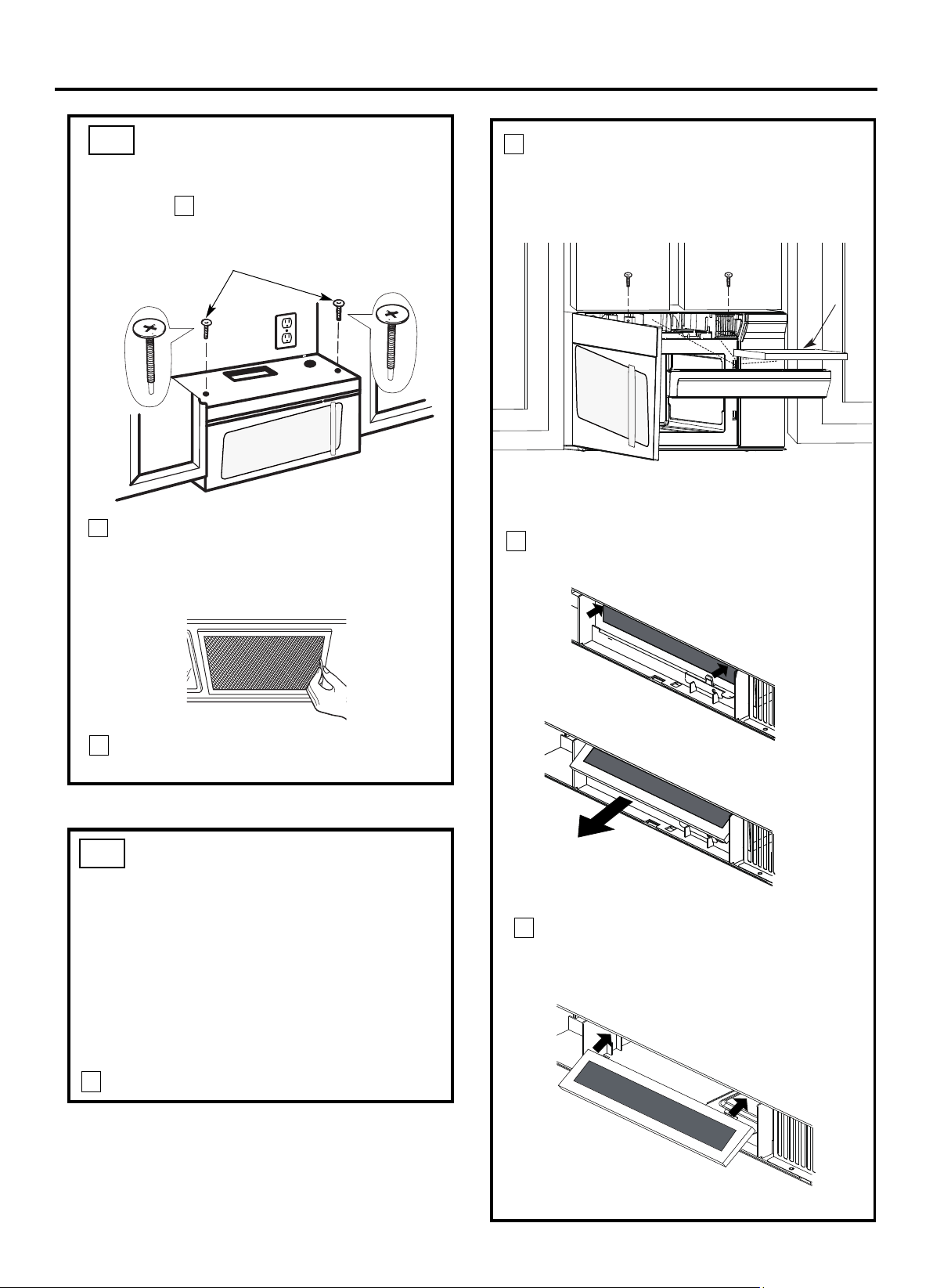
Attach th e plate to the wall using toggle bolts.
At least one wood screw must be used to attach
th e plate to a wall stud.
Remove the toggle wings from th e bolts.
Insert the bolts into th e mounting plate
th rough th e h oles design ated to go in to drywall
and reattach the toggle wings to
3
⁄4″ ( 19 mm) onto
each bolt.
1
INSTALLATION OVERVIEW
A1. Attach Mountin g Plate to Wall
A2. Prepare Top Cabinet
Mount Microwave O ven
A5.
Adjust Exhaust Adaptor
A6.
Wall
M ounting
Plate
Spacing for Toggles
M ore Than Wall
Thickness
Bolt End
Toggle
Bolt
Toggle Wings
To use toggle bolts:
Installation Instructions
2
OUTSIDE TOP EXHAUST (Vertical Duct)
A
IMPORTANT NOTES:
• Make sure the screws for the
blower motor and blower plate
are securely tightened when
th ey are reinstalled. This will
help to prevent excessive
vibration.
• Make sure the motor wirin g h as
been properly routed and secured,
and that the wires are not pinch ed.
A7. Connect Ductwork
A3.
A4.
Check Damper Operation
Adapting Microwave Blower for
Outside Top Exhaust
12"
4"
NO
TE
: IT IS VERY
I
MPOR
TANT TO
READ AND FO
LLOWTHE DIRECTIONS
IN THE INSTALLATION INSTRU
CTI
ONS
BE
FO
RE PR
O
CEEDINGWITH TH
IS
REAR W
ALL TEMPLATE.
Thi
s
R
ea
rWall Templ
ate ser
ves to p
osition the botto
m
mounting platea
nd
to locate the hor
izon
ta
l exhau
st
ou
t
let.
1. Us
e a l
ev
elto check th
at the t
emplate is pos
itioned
accu
r
ately.
2. L
oc
ate a
ndmar
k at lea
st o
nestud on the left or
right
side of the centerli
ne.
016'
It is importa
nt to use at leas
t
one wo
od
sc
rew
mounted firmly
i
n a s
tud
to support the weight
of
the mic
r
owa
ve. M
ark two additional, even
ly
spa
ced
locatio
ns fo
r
the
supplied to
g
gle bol
t
s.
3. Dri
ll
h
ole
s in th
e marked locatio
ns.
Wher
e t
h
er
e is
a stud, dr
il
l
a 3/1
6"
hole for wood scr
ews. F
or
holes
thatdo
n
o
t lin
e upwith
a stud, dr
ill 5
/8" holes for
togg
le bolts
.
016'
DO
NOT
INSTALL
T
HE MOUNTI
NG P
L
ATE
AT THISTIME.
4. Re
move the template fr
o
m
the rea
r
wall.
5.Review
the Insta
ll
a
tionInstr
uc
tion book
for your
installa
tion situat
i
on
.
Locate and mark holes
to align with holes in t
he
mounting
plate.
IMP
O
RTANT
:
LOCATE
AT LEAST ONE STUD
ON EI
THERSIDE OF
THE CENTE
RLINE.
MARKTHE LOCATION FOR 2 ADDITIONAL, EVENLY
SP
ACE
D T
OGGLE
BOLTS IN THE MOUN
TING
PLATE
AREA.
Trim the re
ar wall tem
plat
e along
the do
tted line.
Da
rle
vu
elt
a
a
la
ho
ja
pa
ra
co
ns
ul
tarla
ver
sión
en
Españo
l.
Locate and mark
holes to ali
gn with holes in t
he
mountingplate.
IMPORTANT:
LOC
A
TE AT LEAST ONESTUD ON EITHER SI
D
E OF
THE
CENT
E
R
LI
N
E
.
MARKTHE LO
CATION
FOR 2 ADDITIONA
L, EV
ENL
Y
SPACEDTOGGLE BOLTS IN THE MO
UNTING PLATE
AREA.
Trim the rear wall templat
e along
the dotted line.
3/8"TO
EDG
E
EN-12
Tigh ten all bolts. Pull the plate away from th e wall
touch th e bottom of the Rear wall template wh en
pushed flush again st th e wall and th at th e plate is
properly
USE TOP CABINET TEM PLATE
FOR PREPARATION OF TOP
CABINET
You n eed to drill h oles for th e top support screws, a
hole large en ough for th e power cord to fit through,
and a cutout large enough for th e exh aust adaptor.
A2.
• Read th e instruction s on the TOP CABINET
TEMPLATE.
• Tape it underneath the top cabin et.
• Drill the holes, followin g the in structions on the
TO P CABINET TEMPLATE.
CAUTION: Wear safety goggles when drillin g h oles
in th e cabinet bottom.
Installation Instructions
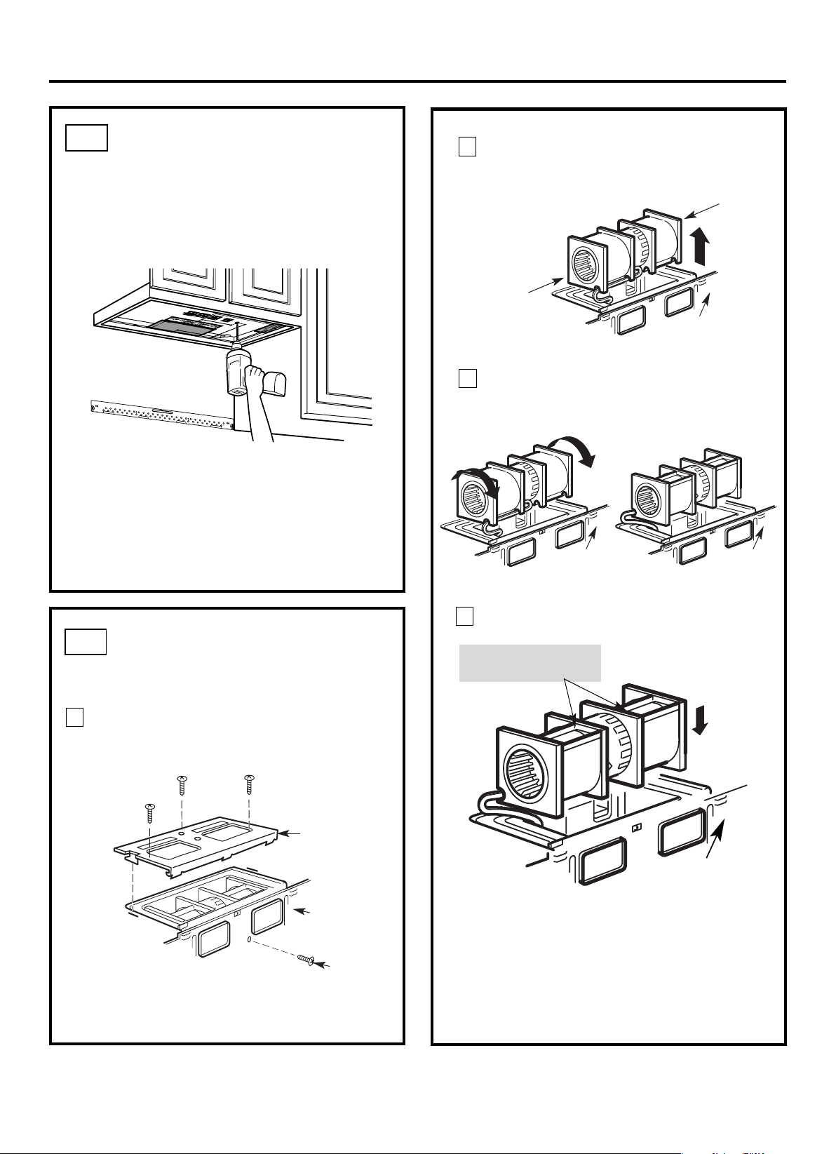
A3.
Remove the screw th at holds the blower plate
to the microwave. Remove and save the screw
holding th e blower motor to the microwave.
Blower Plate
Blower M otor
Screw
Back of
M icrowave
2
Carefully pull out th e blower unit. Th e wires
will exten d far enough to allow you to adjust
th e blower unit.
1
ADAPTING MICROWAVE
BLOWER FOR OUTSIDE
TOP EXHAUST
Roll the blower un it 90° so that fan blade
microwave.
3
Back of
M icrowave
Before Rotation After Rotation
Back of
M icrowave
openin gs are facin g out th e top of th e
Back of
M icrowave
AFTER: Fan Blade
Place the blower un it back in to the opening.
Openings Facing Top
CAUTION: Do not pull or stretch the blower
unit wiring. Make sure the wires are not
pinched, and that they are properly secured.
4
with the top of the un it facing up.
Place the microwave in its uprigh t position,
EN-13
End B
End A
Back of
Microwave
3
MOUNT THE MICROWAVE
OVEN
FOR EASIER INSTALLATIO N AND PERSO NAL
SAFETY, WE RECOMMEND THAT TWO PEOPLE
INSTALL THIS MICROWAVE OVEN.
NOTE: If your cabinet is metal, use th e nylon
grommet aroun d th e power cord hole to prevent
cuttin g of th e cord.
NOTE: We recommend using filler blocks if th e
cabin et front h angs below th e cabinet bottom shelf.
IMPORTANT: If filler blocks are
not used, case damage may occur from
overtightening screws.
turnin g the screw at least two full turns after the
th reads have engaged. (It will be completely
tightened later.) Be sure to keep power cord
tight. Be careful not to pinch the cord, especially
when mounting flush to bottom of cabinet.
2
Rotate front of oven
up against cabin et
bottom.
NOTE: When moun ting the
microwave oven, thread
power cord through hole in
bottom of top cabin et. Keep
it tight throughout Steps
1–3. Do n ot pin ch cord or
lift oven by pulling cord.
Lift microwave, tilt it
forward, an d hook
slots at back bottom
edge onto four lower
tabs of mountin g
plate.
1
CHECK FOR PROPER
DAMPER OPERATION
Exhaust Adaptor
Blower Plate
Damper
Back of
M icrowave
• Make sure tape securing damper is removed and
damper pivots easily before mounting microwave.
• You will need to make adjustmen ts to assure proper
alignment with your house exh aust duct after th e
microwave is installed.
A3.
ADAPTING MICROWAVE
BLOWER FOR OUTSIDE
TOP EXHAUST
Secure blower unit to microwave with the screw
5
removed in Step 1. Make sure the screw is tigh t.
Back of
M icrowave
6
7
Back of
M icrowave
Guide
Adapter
Locking Tab
damper swings freely.
Attach th e exh aust adaptor to the top of the
blower plate by sliding it in to the guides
of the
blower plate.
Push in securely until it is in th e locking
tabs.
Take care to assure that the damper hinge
is
installed so that the
A4.
A5.
Installation Instructions
IMPORTANT: Do not grip or use the handle
or heat shield during installation. Do not
remove the cardboard spacers between the
heat shield and door.
EN-14
Insert a self-align in g screw through
Temporarily secure th e oven by
one of the top
cabinet holes.
Step 1. Make sure the screws are tight.
Replace blower plate with the screws removed in

4
Attach th e microwave oven to th e top cabin et.
8
7
Cabinet Front
Cabinet Bottom Shelf
Tigh ten the outer two screws to the top of the
microwave oven. ( Wh ile tightening screws, hold
th e microwave oven in place again st th e wall and
th e top cabin et.)
Filler Block
M icrowave Oven Top
Equivalent
to Depth
of Cabinet
Recess
Install grease filters. See th e Use &&&&an d Care
packed with the microwave.
Installation Instructions
ADJUST THE EXHAUST
ADAPTOR
Open th e top cabin et and adjust th e exh aust adaptor
to conn ect to the h ouse duct.
Back of
M icrowave
For Front-to-Back or
Side-to-Side Adjustment,
Slide the Exhaust Adaptor
as Needed
Blower Plate
Damper
Self-Aligning Screw
5
MOUNT THE MICROWAVE
OVEN (cont.)
A6.
A5.
CONNECTING DUCTWORK
1
2
Extend the h ouse duct down to connect to
th e exh aust adaptor.
A7.
furnance
Seal exh aust duct join ts using duct tape
for high temperature applications.
EN-15
House Duct
Insert 2nd self aligning
screw through remaining
top cabinet hole.
Turn two full turns on screw.
INSTALLATION OVERVIEW
B1. Prepare Rear Wall
B3. Attach Mountin g Plate to Wall
B4. Prepare Top Cabin et
B5. Adjust Blower
B6. Mount the Microwave Oven
IMPORTANT NOTES:
• Make sure the screws for the
blower motor and blower plate
are securely tightened when
th ey are reinstalled. This will
help to prevent excessive
vibration.
•
been properly routed and secured,
and that the wires are not pinch ed.
Remove and save the screw that holds the blower
plate to the microwave. Lift off the blower plate.
Back of
M icrowave
Installation Instructions
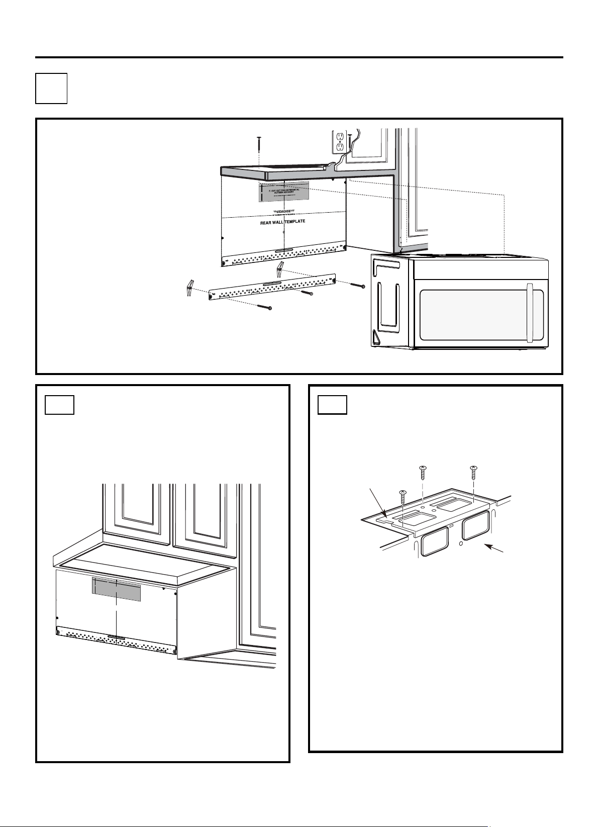
PREPARING THE REAR WALL
FOR OUTSIDE BACK EXHAUST
B1.
You n eed to cut an opening in the rear wall for
outside exh aust.
• Read th e in structions on the REAR
WALL TEMPLATE.
• Tape it to th e rear wall.
• Cut th e opening, followin g the in structions of the
REAR WALL TEMPLATE.
B2.
OUTSIDE BACK EXHAUST (Horizontal Duct)
B
Blower Plate
REMOVE BLOWER PLATE
B2. Remove Blower Plate
3/8" TO EDGE
NOTE: IT IS VE
RY IMPORTANT TO
READ AND FOLLOW THE DIRECTIONS
IN THE IN
STALLATION INSTRUCTIONS
BEFORE PROCEED
ING WITH THIS
REAR WALL TEMPLATE.
This Rear Wall Template serves to position the bottom
mounting plate and to locate the horizontal exhaust
outlet.
1. Use a level to check that the template is positioned
accurately.
2. Locate and mark at least one stud on the left or
right side of the centerline.
It is important to use at least one wood
screw mounted firmly in a stud to support the weight
of the microwave. Mark two additional, evenly spaced
locations for the supplied toggle bolts.
3. Drill holes in the marked locations. Where there is
a stud, drill a 3/16" hole for wood screws. For holes
that do not line up with a stud, drill 5/8" holes for
toggle bolts.
DO NOT INSTALL THE MOUNTING PLATE
AT THIS TIME.
4. Remove the template from the rear wall.
5. Review the Installation Instruction book for your
installation situation.
Locate and mark holes to align with ho
les in the
mounting plate.
IMPORTANT:
LOCATE AT LEAST ONE STUD ON EITHER SIDE OF
THE CENTERLINE.
MARK THE LOCATION FOR 2 ADDITIONAL, EVENLY
SPACED TOGG
LE BOLTS IN THE MOUNTING PLATE
AREA.
Locate and mark holes to align with holes in the
mounting plate.
IMPORTA
NT:
LOCATE AT LEAST ONE STUD ON EITHER SIDE OF
THE CENTERLINE.
MARK THE LOCATION FOR 2 ADDITIONAL
, EVENLY
SPACED TOGGLE BOLTS IN THE MOUNTING PLATE
AREA.
Trim the rear wall templa
te along the dotted line.
Trim the rear wall template along the dotted line.
12"
4"
Darle vuelta a la hoja para consultar la
versión en Español.
Make sure th e motor wiring h as
12"
4"
NO
TE
: IT IS VERY
I
MPOR
TANT TO
READ AND FO
LLOWTHE DIRECTIONS
IN THE INSTALLATION INSTRU
CTI
ONS
BE
FO
RE PR
O
CEEDINGWITH TH
IS
REAR W
ALL TEMPLATE.
Thi
s
R
ea
rWall Templ
ate ser
ves to position th
e bottom
mounting platea
nd
to loc
ate th
e hor
izon
ta
l e
xhau
st
outlet.
1. Use a level
to
chec
k th
at the t
emplate is pos
itioned
accu
r
ately.
2. L
oc
ate andmark at lea
st onestud on the left or
right
side of the centerli
ne.
016'
It is importa
nt to use at leas
t
one wood
sc
rew
mounted firmly in a stud
to supp
ort the weight
of
the mic
r
owa
ve. M
ar
k two ad
dition
al, even
ly
spaced
locatio
ns f
o
r
the
supplied to
g
gle bol
t
s.
3. Drill
h
ole
s in th
e marked locatio
ns.
Where t
h
er
e is
a s
tud, dr
il
l
a 3/1
6" hole for wood scr
ews. F
or
holes
thatdo
n
o
t line upwith a
stud, d
r
ill 5
/8" holes fo
r
togg
le bolts
.
016'
DO
NOT
INSTALL
T
HE MOUNTI
NG P
L
ATE
AT THISTIME.
4. Re
move th
e te
mplate fr
o
m
the rear wall.
5.Review
the In
s
talla
tionInst
r
uction book
for y
ou
r
installa
tion situat
i
on
.
Locate and mark holes
to ali
gn with holes in t
he
mounting
plate.
IMP
O
RTANT
:
LOCATE
AT LEAST ONE STUD
ON EI
THERSIDE OF
THE CENTE
RLINE.
MARKT
HE LO
CATIONF
O
R 2 ADDITIONAL, EVENLY
SP
ACE
D T
OGGLE
BOLTS IN THE MOUN
TING
PLATE
AREA.
Trim the re
ar wall tem
plat
e along
the do
tted line.
Da
rle
vu
elt
aa
la
ho
japara
co
nsultarla
ver
sión
en
Espa
ñol.
Locate and mark
holes to ali
gn with holes in t
he
mountingplate.
IMPORTANT:
LOC
A
TE AT LEAST ONESTUD ON EITHER SI
D
E OF
THE
CENT
E
R
LI
N
E
.
MARKTHE LO
CATION
FOR 2 ADDITIONA
L, EV
ENL
Y
SPACEDTOGGLE BOLTS IN THE MO
UNTING PLATE
AREA.
Trim the rear wall templat
e along
the dotted line.
3/8"TO
EDG
E
EN-16
ATTACH THE MOUNTING
PLATE TO THE WALL
B3.
•
Read th e in structions on th e TOP CABINET
TEMPLATE.
• Tape it underneath the top cabin et.
• Drill the holes, followin g the in structions on the
TO P CABINET TEMPLATE.
CAUTION: Wear safety goggles when drillin g h oles
in th e cabinet bottom.
Wall
M ounting
Plate
Spacing for Toggles More
Than Wall Thickness
Toggle
Bolt
Toggle Wings
To use toggle bolts:
Bolt End
Installation Instructions
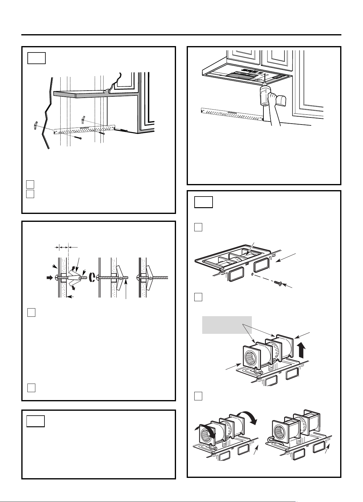
Attach th e plate to the wall using toggle bolts.
At least one wood screw must be used to attach
th e plate to a wall stud.
Remove the toggle wings from th e bolts.
Insert the bolts into th e mounting plate through
th e holes designated to go into drywall and reattach
th e toggle wings to
3
⁄4″ ( 19 mm) onto each bolt.
1
2
Place the mounting plate against th e wall and
insert the toggle wings into the h oles in the wall
to mount the plate.
NOTE: Before tightening toggle bolts and wood
screw, make sure the bottom of th e mounting plate
centered un der the cabin et.
CAUTION: Be careful to avoid pinching fingers
between th e back of the moun ting plate and th e wall.
Tigh ten all bolts. Pull the plate away from th e wall
to h elp tigh ten the bolts.
3
4
2
1
Remove and save screw that holds blower motor
to microwave.
ADAPTING MICROWAVE
BLOWER FOR OUTSIDE
BACK EXHAUST
B5.
End B
End A
will exten d far enough to allow you to adjust
th e blower unit.
Back of
M icrowave
Blower M otor
Blower M otor
Screw
Forward
Openings Facing
Carefully pull out th e blower unit. Th e wires
Before: Fan Blade
USE TOP CABINET TEM PLATE
FOR PREPARATION OF TOP
CABINET
B4.
You n eed to drill h oles for th e top support screws and
a h ole large enough for th e power cord to fit through.
Back of
M icrowave
Roll the blower un it 90°
Back of
M icrowave
3
Before Rotation After Rotation
EN-17
touch th e bottom of the when
pushed flush
rear wall template
against th e wall and that the plate is
properly
Attach th e exh aust adaptor to the rear of the
oven by sliding it into the guides at th e top
center of the back of th e oven.
AFTER: Fan Blade
Openings Facing Back
Place the blower un it back in to the opening.
Replace the blower plate in th e same position
is tight.
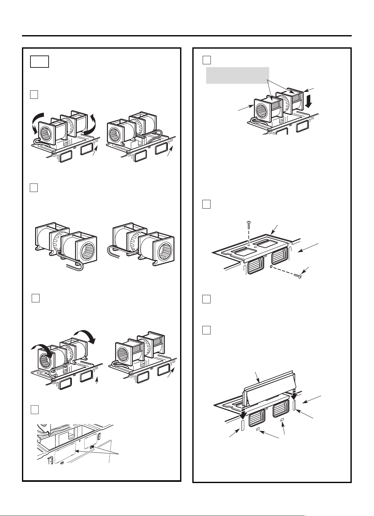
Roll the blower un it 90° so that fan blade
openin gs are facin g out th e back of the
microwave.
ADAPTING MICROWAVE
BLOWER FOR OUTSIDE
BACK EXHAUST (cont.)
B5.
Rotate blower unit coun terclockwise 180°.
Before Rotation After Rotation
Gently remove the wires from th e grooves.
Reroute th e wires through grooves on other side
of the blower un it.
Before Rerouting After Rerouting
Wires Routed Through Right Side
Wires Routed Through Left Side
Back of
M icrowave
Back of
M icrowave
Blower Plate
Blower M otor
Screw
Secure the blower unit to the microwave with
Before Rolling After Rolling
Back of
M icrowave
End A
End B
Back of
M icrowave
Back of
M icrowave
CAUTION: Do not pull or stretch the blower
unit wiring. Make sure the wires are not
pinched, and that they are properly secured.
NOTE: The blower unit exhaust
openings should match exhaust
openings on rear of microwave oven.
Installation Instructions
Push in securely until it is in th e lower locking
tabs. Take care to assure that the damper hinge
is installed so that it is at the top and th at th e
damper swings freely.
Guide
Guide
Adaptor
Locking Tabs
Back of
M icrowave
4
5
6
11
Back of mircrowave
Knockout Plates:
each knockout panel
and remove the metal
knockouts for rear airflow.
Please take care to
rem ove any sharp edges
created from removing
the knockout plates.
7
8
9
10
with snips. (For some models)
Remove the knockout plates in the back of the unit
EN-18
as before with th e screws
th e origin al screws.
Snip all 4 tabs on
Attach th e microwave oven to th e top cabin et.
Installation Instructions
3
MOUNT THE MICROWAVE
OVEN
B6.
FOR EASIER INSTALLATIO N AND PERSO NAL
SAFETY, WE RECOMMEND THAT TWO PEOPLE
INSTALL THIS MICROWAVE OVEN.
NOTE: If your cabinet is metal, use th e nylon
grommet aroun d th e power cord hole to prevent
cuttin g of th e cord.
NOTE: We recommend using filler blocks if th e
cabin et front h angs below th e cabinet bottom shelf.
IMPORTANT: If filler blocks are not
used, case damage may occur from
overtightening screws.
turnin g the screw at least two full turns after the
th reads have engaged. (It will be completely
tightened later.) Be sure to keep power cord
tight. Be careful not to pinch the cord, especially
when mounting flush to bottom of cabinet.
8
7
5
Cabinet Front
Cabinet Bottom Shelf
microwave oven. ( Wh ile tightening screws, hold
th e microwave oven in place again st th e wall and
th e top cabin et.)
Filler Block
M icrowave Oven Top
Equivalent
to Depth
of Cabinet
Recess
packed with the microwave.
Self-Aligning Screw
4
2
Rotate front of oven
up against cabin et
bottom.
NOTE: When moun ting the
microwave oven, thread
power cord through hole in
bottom of top cabin et. Keep
it tight throughout Steps
1–3. Do n ot pin ch cord or
lift oven by pulling cord.
Lift microwave, tilt it
forward, an d hook
slots at back bottom
edge onto four lower
tabs of mountin g
plate.
1
Install grease filters. See th e Use &&&&an d Care
IMPORTANT: Do not grip or use the handle
or heat shield during installation. Do not
remove the cardboard spacers between the
heat shield and door.
EN-19
Insert 2nd self aligning
screw through remaining
top cabinet hole.
Turn two full turns on screw.
Tigh ten the two screws to the top of the
Temporarily secure th e oven by
Insert a self-align in g screw through
one of the top
cabinet holes.

INSTALLATION OVERVIEW
C1. Attach Mountin g Plate to Wall
C2. Prepare Top Cabin et
C4.
C5.
Mount the Microwave Oven
Installation Instructions
Place the mounting plate against th e wall and
insert the toggle wings into the h oles in the wall
to mount the plate.
NOTE: Before tightening toggle bolts and wood
screw, make sure the bott m of the mountin g plate
centered un der the cabin et.
CAUTION: Be careful to avoid pinching fingers
between th e back of the moun ting plate and th e wall.
Tigh ten all bolts. Pull the plate away from th e wall
to h elp tigh ten the bolts.
4
3
ATTACH THE MOUNTING
PLATE TO THE WALL
C1.
Attach th e plate to the wall using toggle bolts.
At least one wood screw must be used to attach
th e plate to a wall stud.
Remove the toggle wings from th e bolts.
Insert the bolts into th e mounting plate through
th e holes designated to go into drywall and
reattach th e toggle wings to
3
⁄4″ (19 mm) onto
each bolt.
1
Wall
M ounting
Plate
Spacing for Toggles
M ore Than Wall
Thickness
Bolt End
Toggle
Bolt
Toggle Wings
To use toggle bolts:
2
RECIRCULATING (Non-Vented Ductless)
C
Install or ch an ge Ch arcoal Filter
C3. Check Blower Plate
NOTE:
CabinetCabinet
If the cabinet depth including the cabinet doors
is more than 13""'' then the unit must be spaced
out from wall using adequate materials supporting
150 Ibs to allow proper top ven t air exhaust/ intake.
o
EN-20
12
"
4"
NO
T
E
:IT I
S VER
Y I
MP
ORTANT
T
O
R
EAD AN
D F
O
LLO
W
T
H
E DIRECTIONS
I
N
T
H
E
INST
ALL
ATIO
N
I
NSTR
UCTION
S
BE
F
ORE PR
O
C
EE
D
I
NGW
IT
H
T
HIS
REAR W
ALL TEM
PL
AT
E
.
This
R
e
ar
Wa
ll
Temp
la
te serves to
positionthe b
ottom
mo
unti
n
g pl
a
tea
n
d
to
loca
t
eth
e
h
or
izo
nt
al exh
aust
ou
tle
t
.
1
.Use a lev
elto check th
a
t
t
h
e
te
mp
late
i
sp
ositi
o
ne
d
a
ccuratel
y.
2. L
o
ca
te a
n
d
ma
rk at
l
east o
ne
stu
d
o
n
th
e lef
t
o
r
r
igh
t si
d
e o
f
thec
en
te
rline.
It
isimporta
nt
to
u
s
e
a
t le
a
sto
n
e wood
screw
mou
nte
d
fi
rm
ly
in a
s
tu
d
tosu
p
p
o
rt
t
he
weigh
t
of themicrowave. Mark two
addi
tio
nal,even
lyspace
d
locationsfor the su
ppliedt
ogg
le
b
ol
ts.
3
. Drill holes
inth
e m
arked lo
ca
tio
ns
.Wh
e
re the
r
eis
a s
tud
,d
rilla
3/16
"
ho
le
f
or
wo
o
d
sc
r
e
ws. F
or
ho
les
th
a
t
do
n
ot
lin
e u
p
with a
stud
, drill5
/8
"
h
o
le
s
f
o
r
to
g
g
le bolt
s.
DO
N
OT
I
N
S
TALL TH
E
MOU
NTINGP
LA
TE
A
T
THIS
TIM
E.
4
. Re
m
ove
th
e te
mp
lat
e fro
m t
he
rea
r
wa
l
l.
5. Reviewthe
I
n
sta
lla
ti
on
In
stru
cti
onb
o
o
k f
or
you
r
in
st
allation
si
tu
a
tio
n
.
Loc
a
t
ean
d
ma
rk holes to
a
lign with holes in the
mount
i
ng pl
ate.
I
MPORT
ANT:
LOCA
T
E AT
LEAST ONESTUD
O
N
EI
T
H
ER SIDE
OF
T
H
E
CE
N
TE
R
L
I
NE.
MARK T
HEL
O
CA
T
IO
N F
O
R2 ADDITION
AL, EVENLY
SPACED TO
G
GLE BOLT
S
IN TH
E
MO
U
N
TING
PLATE
AREA
.
Loc
at
e
a
nd
mark hole
s
t
o
al
i
gn
wi
t
h hol
es
int
h
e
m
o
un
tin
g
p
lat
e.
I
MPO
RTA
NT
:
LO
C
AT
E
AT LEAST
O
NEST
UD
ON EITHER SIDE
O
F
THECENT
E
RLINE.
MARK T
H
E
LOCA
TION F
OR
2 AD
DIT
ION
AL
,
EVENLY
SPACED TOG
G
LE
BO
L
T
SIN
T
H
E
MOUNT
IN
GPLATE
AREA.
T
r
im the rear wa
ll te
m
plate
alon
g
th
e
d
o
tted
li
n
e.
Dar
le
v
uel
taa la ho
ja
par
aconsul
t
ar
la
v
e
r
s
ió
ne
n
Es
p
año
l.
3/8"TO
EDG
E
Trim t
he
rear wall t
em
pla
t
e along
t
h
e dotted lin
e.
touch th e bottom of the Rear wall template wh en
pushed flush
against th e wall and that the plate is
properly
Installation Instructions
Attach th e microwave oven to th e top cabin et.
Cabinet Front
Cabinet Bottom Shelf
Filler Block
M icrowave Oven Top
Equivalent to Depth
of Cabinet Recess
3
MOUNT THE MICROWAVE OVEN
FOR EASIER INSTALLATIO N AND PERSO NAL
SAFETY, WE RECOMMEND THAT TWO PEOPLE
INSTALL THIS MICROWAVE OVEN.
NOTE: If your cabinet is metal, use th e nylon
grommet aroun d th e power cord hole to prevent
cuttin g of th e cord.
NOTE: We recommend using filler blocks if th e
cabin et front h angs below th e cabinet bottom shelf.
IMPORTANT: If filler blocks are not used,
case damage may occur from overtightening
screws.
turnin g the screw at least two full turns after the
th reads have engaged. (It will be completely
tightened later.) Be sure to keep power cord
tight. Be careful not to pinch the cord, especially
when mounting flush to bottom of cabinet.
Self-Aligning Screw
4
2
Rotate front of oven
up against cabin et
bottom.
NOTE: When moun ting the
microwave oven, thread
power cord through hole in
bottom of top cabin et. Keep
it tight throughout Steps
1–3. Do n ot pin ch cord or
lift oven by pulling cord.
Lift microwave, tilt
it forward, an d hook
slots at back bottom
edge onto four lower
tabs of mountin g
plate.
1
C3.
C4.
USE TOP CABINET TEM PLATE
FOR PREPARATION OF TOP
CABINET
C2.
•
Read th e in structions on th e TOP CABINET
TEMPLATE.
• Tape it underneath th e top cabin et.
• Drill the holes, followin g the in structions on th e
TO P CABINET TEMPLATE.
CAUTION: Wear safety goggles when drillin g h oles
in th e cabinet bottom.
You n eed to drill h oles for th e top support screws and
a h ole large enough for th e power cord to fit through.
Adjust top template accordingly if th e microwave
is being spaced out from the wall due to cabinet depth
(includin g cabinet doors) of more th n 13"""''.
NOTE:
a
IMPORTANT: Do not grip or use the handle
or heat shield during installation. Do not
remove the cardboard spacers between the
heat shield and door.
EN-21
Insert a self-align in g screw through
Temporarily secure th e oven by
one of the top
cabinet holes.
Installation Instructions
5
MOUNT THE MICROWAVE
OVEN (cont.)
8
7
microwave oven. ( While tightening screws, hold
the microwave oven in place against th e wall and
the top cabinet.)
packed with th e microwave.
C4.
Install grease filters. See th e Use &&&&an d Care
C5.
INSTALLING OR CHANGE
THE CHARCOAL FILTER
(Some M odels)
Unplug microwave oven or disconnect power.
1
NOTE: The charcoal filter is factory installed in some
models. Refer to the Use and Care to see if yours is
factory installed and for replacement in formation.
For models without th e recirculation filter access
3
Open th e microwave door and remove the two
;
2
4
Remove th e charcoal filter by pushing the
top of the filter inwards,then pull it forward
out from the unit.
Slide the top of the new charcoal filter into the
top of the filter cavity.
door,follow these steps to replace or install a charcoal
filter.
EN-22
Charcoal
Filter
Insert 2nd self aligning
screw through remaining
top cabinet hole.
Turn two full turns on screw.
Tighten the two screws to the top of the
Some models have a filter access door.
Refer to the Use and Care to see if yours does.
vent cover mounting screws located on top of the
microwave using a #2 Phillips screwdriver.
Remove the vent cover by pulling it out at the top
and then pulling out.
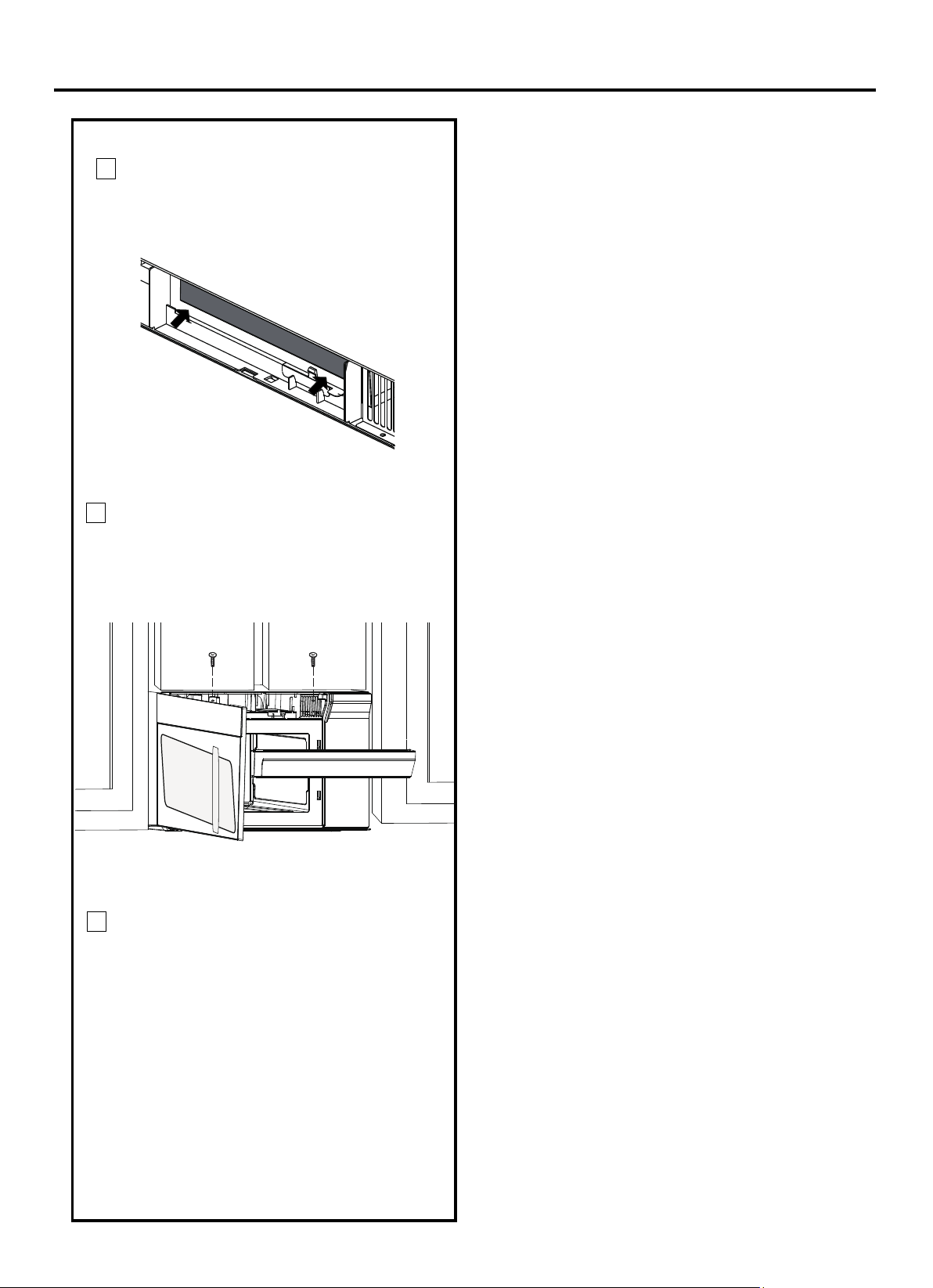
Installation Instructions
C
lose the microwave door. Plug in microwave
oven or reconnect power.
Press th e bottom of charcoal filter to place it
into the correct position.
5
6
7
EN-23
Reinstall the vent cover by pushing the bottom
into place. Push the vent top into position and
hold in place. Replace the two vent cover
mounting screws located on top of the microwave
using a #2 Phillips screwdriver.
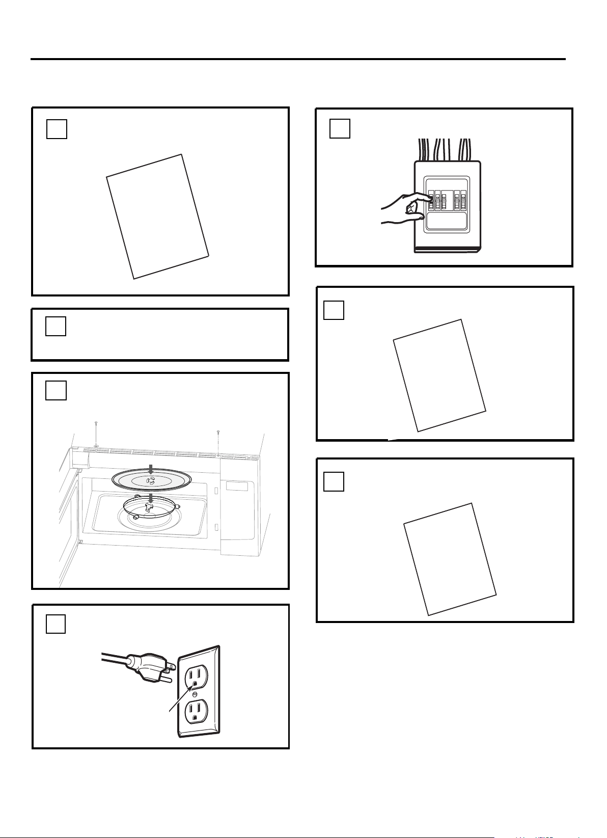
Remove all packing material from th e
microwave oven.
2.
Make sure th e microwave oven h as been
installed accordin g to instruction s.
1.
BEFORE YOU USE YOUR MICROWAVE
Ensure proper
ground exists
before use
3.
Installation Instructions
ring a nd glas s tray in
cavity.
Install turntable
4.
KEEP INSTALLATION
FOR THE LO CAL INSPECTOR’S
USE.
7.
6.
INSTALLATION
MANUAL
USE
|++&=
CARE
+
&
D
G
Read th e Manual.
&
U SE CARE
Replace h ouse fuse or turn breaker back on.
5.
Plug power cord into a seperate an d dedicated
15- to 20-amp electrical outlet.
EN-24
, coupler,
MANUAL
INSTALLATION
MANUAL
Manual.

Prin ted in China
EN-25
Installation Instructions
Operational check
1. Make sure the unit has been installed according to these instructions.
2. Remove all packing materials from the oven.
3. Replace house fuse or turn circuit breaker back on.
4. Plug power cord into receptacle .
5. Read operating instructions before testing the product.
8. Set the microwave oven for 1 minute and confirm the oven is operating normally using a cup of water.
9. Keep these installation instruction for the local electrical inspector’s use.
6. Turn on the exhaust fan at high speed and confirm it is operating by using a tissue (it will stick to the filter).
7. the outdoor exhaust flapper has opened.
For out side vented installations, confirm
3/8" TO EDGE
NOTE: IT IS VERY IMPORTANT TO
READ AND FOLLOW THE DIRECTIONS
IN THE INSTALLATION INSTRUCTIONS
BEFORE PROCEEDING WITH THIS
REAR WALL TEMPLATE.
This Rear Wall Template serves to position the bottom
mounting plate and to locate the horizontal exhaust
outlet.
1. Use a level to check that the template is positioned
accurately.
2. Locate and mark at least one stud on the left or
right side of the centerline.
It is important to use at least one wood
screw mounted firmly in a stud to support the weight
of the microwave. Mark two additional, evenly spaced
locations for the supplied toggle bolts.
3. Drill holes in the marked locations. Where there is
a stud, drill a 3/16" hole for wood screws. For holes
that do not line up with a stud, drill 5/8" holes for
toggle bolts.
DO NOT INSTALL THE MOUNTING PLATE
AT THIS TIME.
4. Remove the template from the rear wall.
5. Review the Installation Instruction book for your
installation situation.
Locate and mark holes to align with holes in the
mounting plate.
IMPORTANT:
LOCATE AT LEAST ONE STUD ON EITHER SIDE OF
THE CENTERLINE.
MARK THE LOCATION FOR 2 ADDITIONAL, EVENLY
SPACED TOGGLE BOLTS IN THE MOUNTING PLATE
AREA.
Locate and mark holes to align with holes in the
mounting plate.
IMPORTANT:
LOCATE AT LEAST ONE STUD ON EITHER SIDE OF
THE CENTERLINE.
MARK THE LOCATION FOR 2 ADDITIONAL, EVENLY
SPACED TOGGLE BOLTS IN THE MOUNTING PLATE
AREA.
Trim the rear wall template along the dotted line.
Trim the rear wall template along the dotted line.
12"
4"
Darle vuelta a la hoja para consultar la
versión en Español.
PN:261800308463
Part No.:77222
316902476
PN:16170000A75584
3/8" TO EDGE
NOTE: IT IS VERY IMPORTANT TO
READ AND FOLLOW THE DIRECTIONS
IN THE INSTALLATION INSTRUCTIONS
BEFORE PROCEEDING WITH THIS
REAR WALL TEMPLATE.
This Rear Wall Template serves to position the bottom
mounting plate and to locate the horizontal exh aust
outlet.
1. Use a level to check that the t emplate is positioned
accurately.
2. Locate and mark at least one stud on the l eft or
right side of t he c enter line .
It is important to use at l east one wood
screw mounted firmly in a stud to support the weigh t
of the microwave. Mark two additional, evenly s paced
locations for the supplied toggl e bol ts.
3. Drill holes in the marked locat i ons. Where ther e is
a stud, drill a 3/1 6" hole f or wood screws. For holes
that do not line up with a s tud, drill 5/8" holes fo r
toggle bolts.
DO NOT INSTALL THE MOUNTING PLATE
AT THIS TIME.
4. Remove the template from the rear wall.
5. Review the Installation Inst ructio n book for your
installation si t uati on.
Locate and mark holes to align with holes in the
mounting plate.
IMPORTANT:
LOCATE AT LEAST ONE STUD ON EITHER SIDE OF
THE CENTERLINE.
MARK THE LOCATION FOR 2 ADDITIONAL, EVENLY
SPACED TOGGLE BOLTS IN THE MOUNTING PLATE
AREA.
Locate and mark holes to align with holes in the
mounting plate.
IMPORTANT:
LOCATE AT LEAST ONE STUD ON EITHER SIDE OF
THE CENTERLINE.
MARK THE LOCATION FOR 2 ADDITIONAL, EVENLY
SPACED TOGGLE BOLTS IN THE MOUNTING PLATE
AREA.
Trim the rear wall template along the dotted line.
Trim the rear wall template along the dotted line.
12"
4"
Darle vuelta a la hoja para consultar la
versión en Español.
3/8" TO EDGE
NOTE: IT IS VERY IMPORTANT TO
READ AND FOLLOW THE DIRECTIONS
IN THE INSTALLATION INSTRUCTIONS
BEFORE PROCEEDING WITH THIS
REAR WALL TEMPLATE.
This Rear Wall Template serves to position the bot tom
mounting plate and to locate the horizontal exhaust
outlet.
1. Use a level to check that the templ ate i s positioned
accurately.
2. Locate and mark at least one stud on the l eft or
right side of t he cent erl i ne.
It is important to use at l east one wood
screw mounted firmly in a stud to support the weight
of the microwave. Mark two additional, evenly spaced
locations for the supplied toggle bolt s.
3. Drill holes in the marked l ocati ons. Where there i s
a stud, drill a 3/16" hol e for wood screws. For holes
that do not line up wit h a stu d, drill 5/8" holes for
toggle bolts.
DO NOT INSTALL THE MOUNTING PLATE
AT THIS TIME.
4. Remove the template from the rear wall.
5. Review the Installation Instr ucti on book f or your
installation si t uati on.
Locate and mark holes to align with holes in th e
mounting plate.
IMPORTANT:
LOCATE AT LEAST ONE STUD ON EITHER SIDE OF
THE CENTERLINE.
MARK THE LOCATION FOR 2 ADDITIONAL, EVENLY
SPACED TOGGLE BOLTS IN THE MOUNTING PLATE
AREA.
Locate and mark holes to align with holes in th e
mounting plate.
IMPORTANT:
LOCATE AT LEAST ONE STUD ON EITHER SIDE OF
THE CENTERLINE.
MARK THE LOCATION FOR 2 ADDITIONAL, EVENLY
SPACED TOGGLE BOLTS IN THE MOUNTING PLATE
AREA.
Trim the rear wall template along the dotted line.
Trim the rear wall template along the dotted line.
12"
4"
Darle vuelta a la hoja para consultar la
versión en Español.
A06823428

CHECK LIST FOR INSTALLATION
1. Make sure the unit has been installed according to all of the Installation lnstructions, the Top Template
and Wall Template.
2. Remove all packing material from the oven.
3. Plug in the power cord.
4. Read the Operation Manual.
5. Keep the Installation Instructions for the local electrical inspector's use.
ACCESSORIES
Check with your dealer or order directly from the SHARP Accessories and Supplies Center.
Call toll-free 1-800-BE SHARP (237-4277).
1. CHARCOAL FILTER (RK233). Fi ter is used when hood exhaust is recirculated only.
2. GREASE FILTER (RK235) .
l

Hornos de Microondas sobre :
MANUAL DE INSTALLACIÓN
SMO1759JS
Adaptación del Ventilador de
Microondas para el Escape
Exterior Trasero .........................
Instalación del Horno de
Microondas .....................................
Recirculación ....................................
Fijación de la Placa de Montaje
a la Pared .......................................
Preparación del Gabinete
Superior ..........................................
Inspección de la Placa del
Ventilador ........................................
Instalación del Horno de
Microondas ................................
Instalación o Sustitución del
Filtro de Carbón ..............................
Precauciones Antes del Uso .........................
Información de la Plantilla .............................
C
ES-2
CONTENIDOS
Información general
Medidas de Seguridad Importantes ...............
Requisitos Eléctricos ......................................
Daños - Envío/Instalación ...............................
Piezas Incluidas ...............................................
Herramientas que Necesitará .........................
Espacio de Montaje .........................................
Guía de instalación paso a paso
3
3
4
4
5
5
Colocación de la Placa de montaje ...........
Eliminación de la placa de montaje .........
Encuentro de los Montantes de Pared ....
Determinación de la Ubicación de la
Placa de Pared ........................................
Alineación de la Placa de Pared ..............
Tipos de Instalación ...................................
Escape de la Campana ............................
A
Ecape Superior Exterior...................
Fijación de la Placa de Montaje
a la Pared ..........................................
Preparación del Gabinete
Superior ............................................
Adaptación del Ventilador de
Microondas para el Escape
Superior Exterior .......................
Comprobación del
Funcionamiento Correcto del
Amortiguador .................................
Instalación del Horno de
Microondas ...............................
14-15
Ajuste del Adaptador de Escape.....
Conductos de Conexión .................
B
Preparación de la Pared
Trasera para el Escape Exterior
Trasero ..........................................
Eliminación de la Placa del
Ventilador .......................................
Fijación de la Placa de Montaje
a la Pared ......................................
Preparación del Gabinete
Superior .........................................
Instrucciones de Instalación
6-8
6
6
7
8
9-23
10-11
12-15
12
13
13-14
14
15
16-19
16
16
17
17
17
–
18
19
20-
20
21
21
21-22
22
24
25
15
Escape Exterior Trasero.................
23
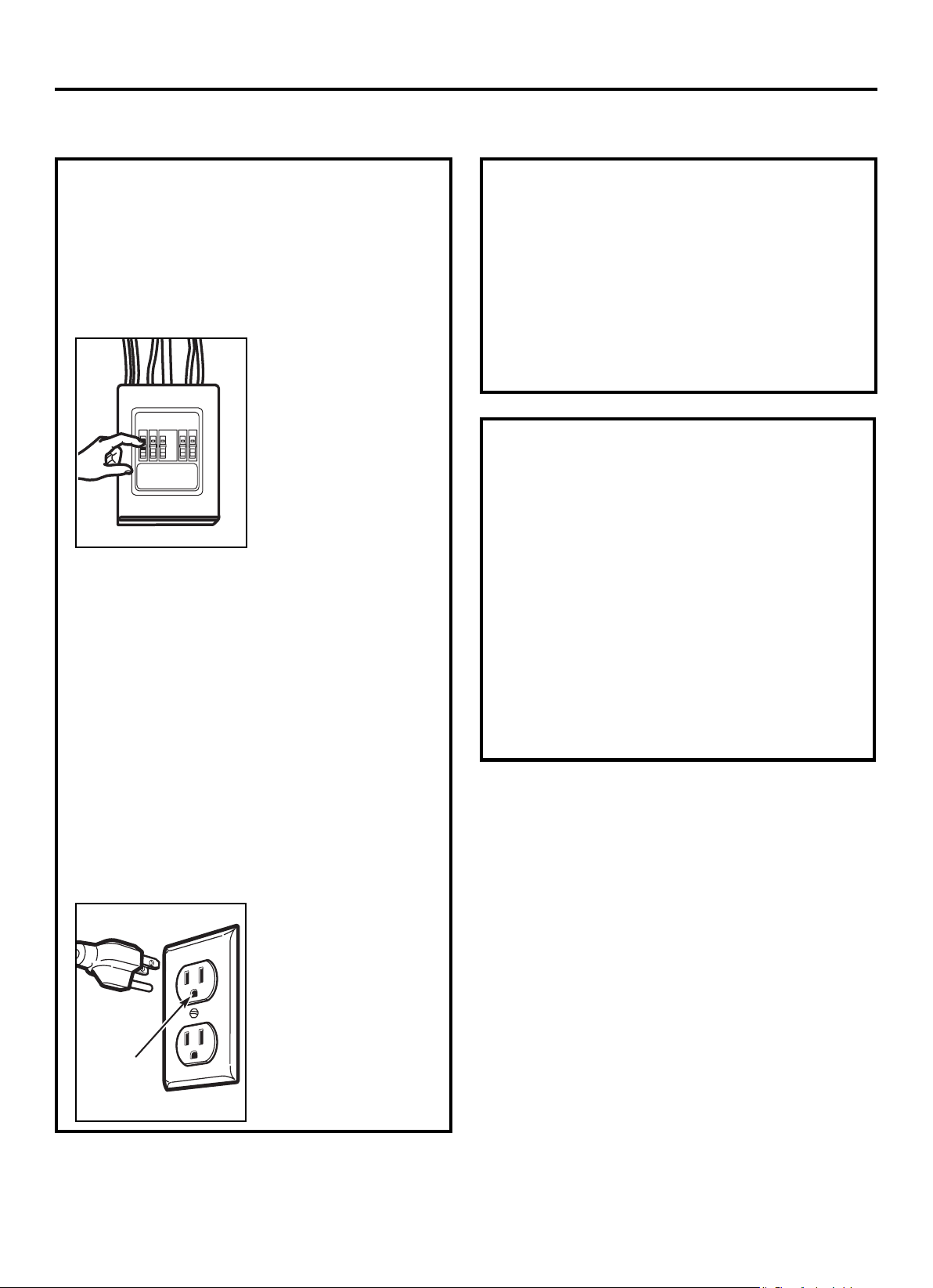
Este producto necesita un tomacorriente con conexión a
tierra de tres clavijas. El instalador debe realizar una
verificación de continuidad de tierra en la caja de salida
de alimentación antes de comenzar la instalación para
asegurarse de que la caja de salida esté debidamente
conectada a tierra. Si no está debidamente conectada a
tierra, o si la caja de salida no cumple con los requisitos
eléctricos indicados (según REQUISITOS ELÉCTRICOS),
se debe contratar a un electricista calificado para corregir
cualquier deficiencia.
PRECAUCIÓN:
Considerando su
seguridad personal,
elimine el fusible de la
casa o abra el disyuntor
antes de empezar la
instalación a fin de evitar
lesiones graves o
fatales.
PRECAUCIÓN: Considerando su seguridad personal,
la superficie de montaje debe ser capaz de soportar
la carga del gabinete, además del peso adicional de
este producto de 63-85 libras (28,5 a 38,5 kg), más
cargas adicionales del horno de hasta 50 libras
(22,7 kg) o un peso total de 113-135 libras (51,3-61,2
kg). PRECAUCIÓN: Considerando su seguridad
personal, este producto no puede instalarse en
arreglos de gabinete como una isla o una península.
Debe estar instalado AMBOS en un gabinete superior
Y en una pared.
NOTA: Con motivo de facilitar la instalación y
garantizar la seguridad personal, se recomienda que
la instalación del producto sea realizada por dos
personas.
IMPORTANTE - POR FAVOR LEA CON ATENCIÓN.
POR SEGURIDAD PERSONAL, ESTE APARATO DEBE
CONECTARSE A TIERRA DEBIDAMENTE PARA
EVITAR DESCARGAS ELÉCTRICAS SEVERAS O
FATALES.
El cable de alimentación
de este electrodoméstico
está equipado con un
conector (a tierra) de tres
clavijas que coincide con
un receptáculo de pared
estándar (a tierra) de tres
clavijas para minimizar los
peligros potenciales de
descargas eléctricas
desde el aparato.
Debe hacer que un electricista calificado verifique el
receptáculo de pared y el circuito para asegurarse de
que el receptáculo esté correctamente puesto a
tierra.
En caso de ser un receptáculo de pared estándar de
dos clavijas, es muy importante que lo sustituya con
un receptáculo de pared de tres clavijas debidamente
conectado a tierra, instalado por un electricista
calificado.
EN NINGÚN CASO PUEDE CORTAR, DEFORMAR NI
RETIRAR NINGUNA DE LAS CLAVIJAS DEL CABLE
DE ALIMENTACIÓN. NO LO UTILICE CON UN CABLE
DE EXTENSIÓN.
Instrucciones de Instalación
Asegúrese de
que exista una
conexión a tierra
correcta antes
del uso
REQUISITOS
ELÉCTRICOS
La clasificación del producto es de 120 voltios CA, 60
Hertz, 15 amperios y 1,6 kilovatios. Debe conectar este
producto a un circuito de alimentación separada y
específica de voltaje y la frecuencia adecuados. El
tamaño del cable debe cumplir con los requisitos del
Código Eléctrico Nacional o el código local vigente para
esta clasificación de kilovatios.
El cable y el enchufe de alimentación deben llevarse a
un tomacorriente individual puesto a tierra de circuito
derivado de 20 amperios separado y específico. La caja
de salida debe localizarse en el gabinete sobre el horno
de microondas. La caja de salida y el circuito de
alimentación deben ser instalados por un electricista
calificado y deben cumplir con el Código Eléctrico
Nacional o el código local vigente.
ES-3
INSTRUCCIONES IMPORTANTES DE SEGURIDAD
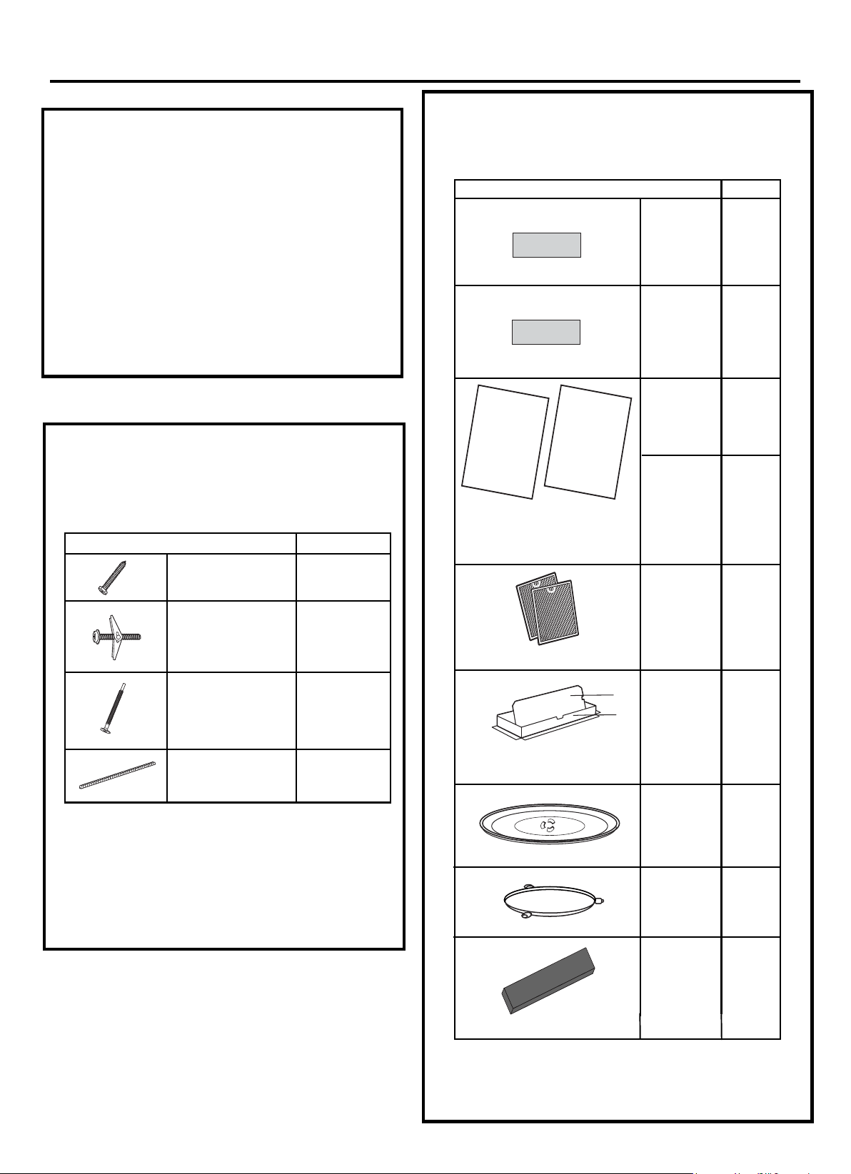
PIEZA
CANTIDAD
Tornillos para
Madera (
1
/
4
"×2")
2
Tornillos de Fiador
(y tuercas de alas)
(
3
/
16
"×3")
3 Tornillos
Autoalineadores para
Máquina
(
1
/
4
"-28×3
1
/
4
")
Ojal de Nylón (para
gabinetes de metal)
1
•
Si la unidad es dañada durante el envío,
devuélvalo a la tienda donde lo compró para
la reparación o sustitución.
Si la unidad es dañada por el cliente, la
reparación o sustitución correrá a cargo del
cliente mismo.
Si la unidad es dañada por el instalador (si
no es el cliente), la reparación o el reemplazo
deben hacerse por acuerdo entre el cliente y
el instalador.
•
•
DAÑOS - ENVÍO
INSTALACIÓN
Instrucciones de Instalación
Encontrará las herramientas de instalación
contenidas en un paquete con la unidad.
Compruebe que tiene todas estas piezas.
NOTA: También hay piezas adicionales incluidas.
PIEZAS INCLUIDAS
PAQUETE DE HERRAMIENTAS
PIEZA
CANTIDAD
1
Instrucciones
de
Installación:
2
PIEZAS INCLUIDAS (CONTENIDAS)
PIEZAS ADICIONALES
1
Adaptador
de
escape
Bandeja de
Cristal
1
1
Anillo del
Plato Giratorio
Plantilla del
Gabinete
Superior
Plantilla de la
Pared Trasera
2
1
Manual de
Uso &
Cuidado
1
Manual de Uso
& Cuidado
1
ES-4
FILTRO DE
CARBÓN
Filtros de
Grasa
Embalados
por Separado
1
Instalación
Manual de
Uso &
Cuidado:
9KL16170000A96484
9KL16170000A96485
9KL12270000008300
1:9KL12270000008424
2:9KL12270000003545
1
2
9KL12270000008304
9KL12570000001005
9KL12170000004327
(9KL12970000000429)
9KL16170000A9 40
5
2
9KL16170000A9 40
2
3
Manual de
Installación
Manual de
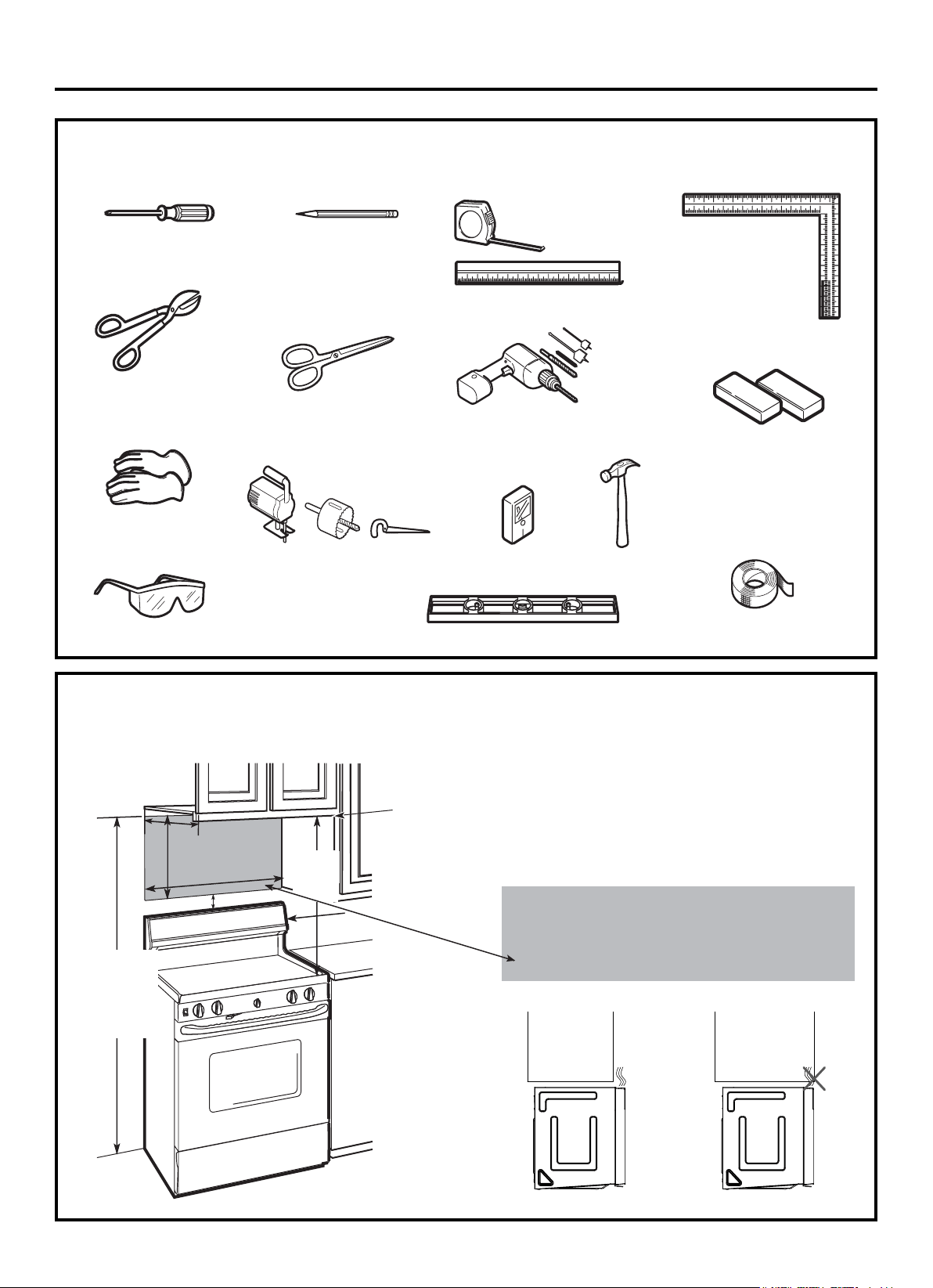
HERRAMIENTAS QUE NECESITARÁ
Lápiz
Regla o cinta métrica
y borde recto
Escuadra de
carpintero
(opcional)
Tijeras de hojalatero
(para cortar el
amortiguador, si es
necesario)
Taladro eléctrico con
brocas de
3
/
16
",
1
/
2
" y
5
/
8
"
Detector de
vigas
Bloques de relleno o
pedazos de madera de
desecho, si es necesario
para el espacio del gabinete
superior (usado solo en
instalaciones de gabinetes
inferiores empotrados)
Guantes
Sierra (sable, agujero u ojo de
cerradura)
Nivel
Cinta adhesiva y de
enmascarar
Instrucciones de Instalación
Tijeras
(para cortar la plantilla,
cuando sea necesario)
Gafas protectoras
ESPACIO DE MONTAJE
NOTAS:
•
El espacio entre los gabinetes debe ser de 30" (76,2 cm)
de ancho y libre de obstáculos.
Si desea ventilar su horno de microondas hacia el
exterior, consulte la Sección de Escape de la Campana
para la preparación del conducto de escape.
Al instalar el horno de microondas debajo de gabinetes
lisos y planos, tenga cuidado de observar las
indicaciones en la plantilla del gabinete superior para
conocer el espacio libre del cable de alimentación.
Como guía para la instalación, véase en la página 25
para la Información de la Plantilla de Montaje.
Si la profundidad del gabinete, incluidas las puertas del
gabinete, es superior a 13", pues la unidad debe estar
separada de la pared por medio de materiales
adecuados que soporten 150 libras para permitir la
entrada/salida de aire de ventilación superior de manera
adecuada.
•
•
El Borde Inferior
del Gabinete
Debe Estar a
30" (76,2 cm) o
Más de la
Superficie de
Cocción
Protector contra salpicaduras
69" (1.5 m)
desde el Piso
hasta la Parte
Superior del
Microondas
30“ (76,2 cm)
2“(5,1cm)
30"
Mínimo
(76,2 cm)
16
1
⁄
2
“
(41,9 cm)
13" Máximo (33 cm)
•
•
ES-5
Destornillador Phillips #2
o
Martillo
(opcional)
o Más
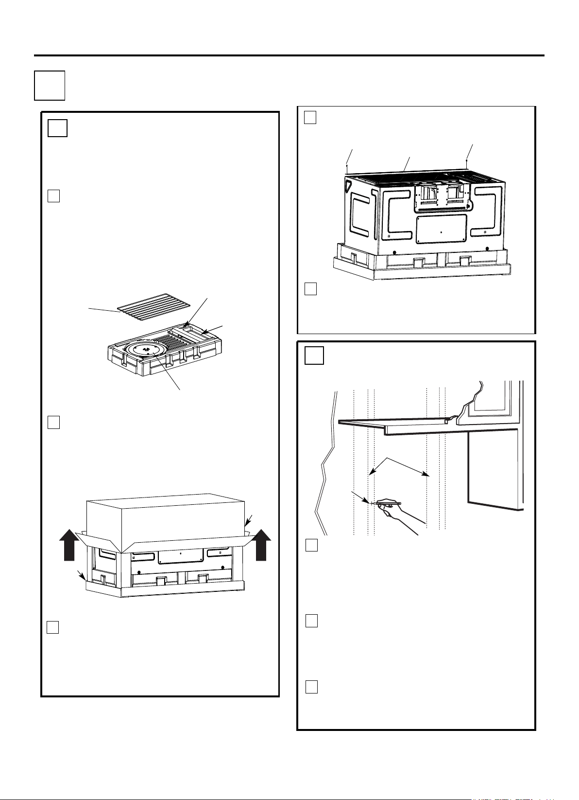
Instrucciones de Instalación
Encuentre los montantes a través de una de las
siguientes maneras:
A. Buscador de montantes - un dispositivo
magnético que localiza los clavos.
B. Use un martillo para golpear ligeramente la
superficie de montaje para encontrar un sonido
sólido.
Esto indicará la posición de un montante.
Después de encontrar los montantes, encuentre
el centro sondeando la pared con un clavo
pequeño para encontrar los bordes del montante.
Luego, coloque una marca a medio camino entre
los bordes. El centro de cualquiera de los dos
montantes adyacentes debe estar a 16" (40,6 cm)
o 24" (61 cm) de esta marca.
Dibuja una línea a lo largo del centro de los
montantes.
EL MICROONDAS DEBE ESTAR CONECTADO
AL MENOS A UN MONTANTE DE PARED.
1
Doble hacia atrás las 4 solapas de la caja
completamente contra los lados de la caja.
Luego, enrolle atentamente el horno y la caja de
cartón hacia la parte superior. El horno debe
estar almacenado en la espuma de poliestireno.
ELIMINACIÓN DEL HORNO
DE MICROONDAS DE LA
CAJA/ ELIMINACIÓN DE LA
PLACA DE MONTAJE
A
.
2
Montantes
de Pared
Centro
3
Tire de la caja hacia arriba y fuera del horno.
2
3
4
Corte la mitad de la bolsa de plástico protectora
exterior para quitar la placa de montaje.
5
Retire los tornillos de cada extremo de la placa de
montaje. Esta placa será utilizada como plantilla
de la pared trasera y para el montaje. Vuelva a
instalar los tornillos en los orificios donde se
retiraron.
ES-6
1
Adaptador de Escape
Filtros y Anillo del Plano Giratorio debajo de
la Bandeja de Vidrio
Bolsa Pequeña de
Herramientas
Estante (Para
algunos
modelos)
Retire la placa de la cubierta superior, las
instrucciones de instalación, uso y cuidado, el
adaptador de escape, el anillo del plato giratorio,
el estante, los filtros, la bandeja de vidrio y la
bolsa pequeña de herramientas. No saque la
espuma de poliestireno que protege la parte
delantera del horno.
Caja de
cartón
Espuma
de
poliestire
no
Placa de Montaje
1 COLOCACIÓN DE LA PLACA DE MONTAJE
Tornillos
Tornillos
B
.
ENCUENTRO DE LOS
MONTANTES DE PARED
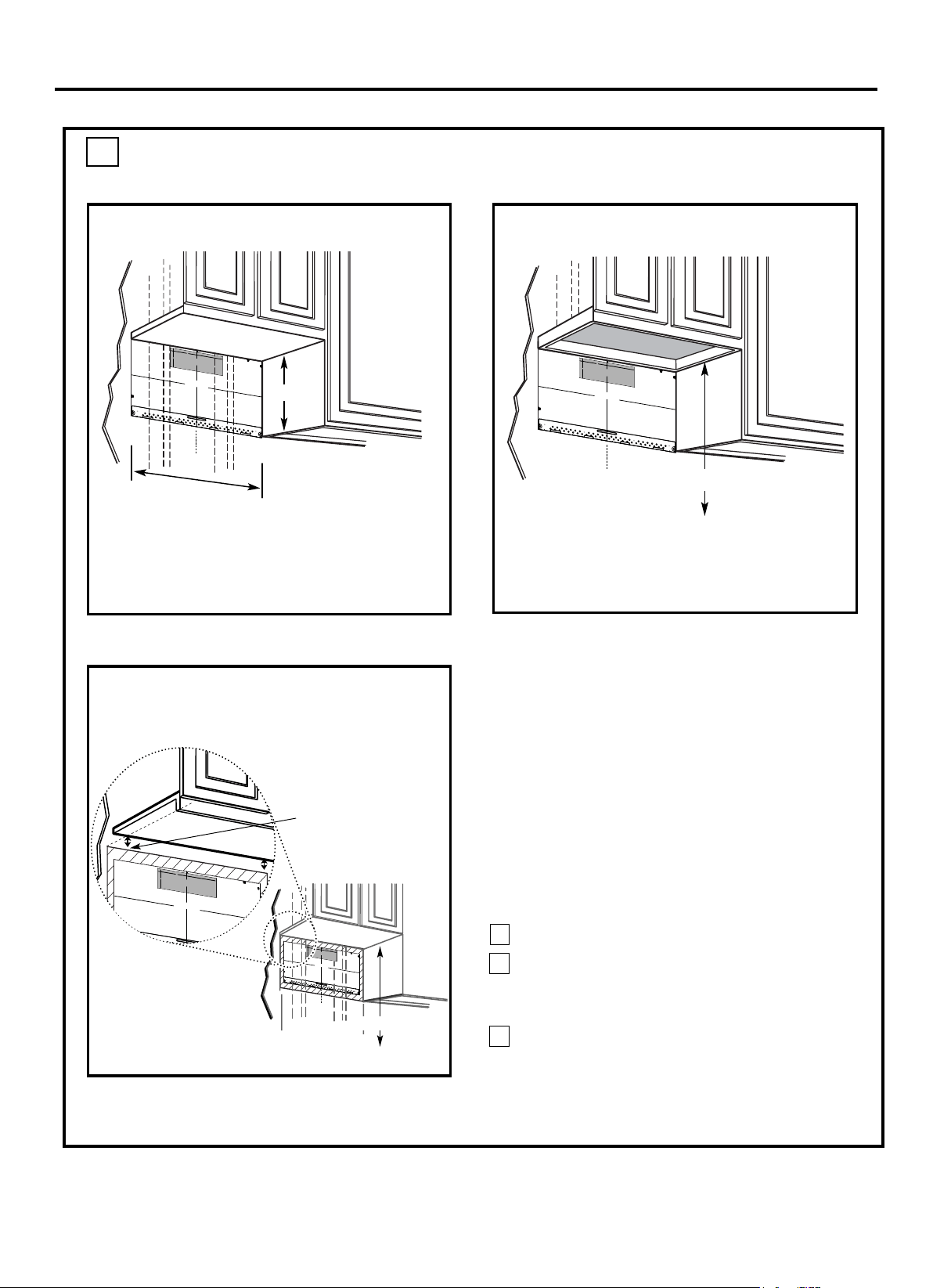
C.
DETERMINACIÓN DE LA UBICACIÓN DE LA PLACA DE PARED
DEBAJO DE SU GABINETE
Instrucciones de Instalación
Posición de la placa - debajo del gabinete
plano inferior
Al menos 30"
Sus gabinetes pueden tener moldura decorativa que
interfiere con la instalación del horno de microondas.
Saque la moldura decorativa para instalar el horno
de microondas y hacerlo nivelado de manera
adecuada.
EL HORNO DE MICROONDAS DEBE ESTAR
NIVELADO.
Use un nivel para asegurarse de que la parte inferior
del gabinete esté nivelada. Si el gabinete solo tiene
un voladizo frontal, sin marco posterior ni lateral,
instale la placa de montaje a la misma distancia que
la profundidad del voladizo delantero. Así se puede
mantener el horno de microondas nivelado.
Mida la profundidad interior del voladizo delantero.
Dibuje una línea horizontal en la pared trasera a
la misma distancia por debajo de la parte inferior
del gabinete que la profundidad interior del
voladizo delantero.
Para este tipo de instalación solo con voladizo
delantero, alinee la plantilla trasera con esta línea
horizontal, sin tener contacto con la parte inferior
del gabinete como se describe en el Paso D.
Dibuje una línea vertical en
la pared en el centro del
espacio de 30".
Pegue con cinta adhesiva
la Plantilla de la Pared
Trasera en la pared
alineándose con la línea
central y teniendo contacto
con el gabinete inferior.
Dibuje una línea vertical en la pared en el centro del
espacio de 30".
Pegue con cinta adhesiva la Plantilla de la Pared
Trasera en la pared alineándose con la línea central y
teniendo contacto con el marco del gabinete inferior.
Posición de la placa-debajo de la parte
inferior del gabinete empotrado enmarcado
Posición de la placa-debajo del
gabinete inferior empotrado con
voladizo delantero
1
3
2
ES-7
16-1/2"
C
3/8" HASTA EL BORDE
PRECAUCIÓN - SI EL ADAPTADOR DE ESCAPE SE SITÚA FUERA DE LA DIMENSIÓN RECOMENDADA, LOS VAPORES
.GRASOS SE DESCARGARÁN EN LA ESTRUCT
URA DE LA CASA
PLANTILLA DE LA PARED TRASERA
NOTA: ES MUY IMPORTANTE LEER Y SEGUIR LAS
INDICACIONES EN LAS INSTRUCCIONES DE INSTALACIÓN
ANTES DE PROCEDER CON ESTA PLANTILLA DE PARED
TRASERA.
Esta Plantilla de Pared Trasera sirve para colocar la placa de montaje
inferior y la salida de escape horizontal.
1. Use un nivel para revisar si la plantilla está posicionada con
precisión.
2. Sitúe y marque al menos un montante en el lado izquierdo o
derecho de la línea central.
NOTA: Es importante usar al menos un tornillo para madera
firmemente montado en un montante para sostener el peso del horno
de microondas. Marque dos posiciones adicionales, que deben ser
uniformemente espaciadas, para los tornillos de fiador suministrados.
3. Perfore orificios en las posiciones marcadas. Perfore un orificio de
3/16" para tornillos para madera donde haya un montante. Para los
orificios que no se alinean con un montante, perfore orificios de 5/8"
para tornillos de fiador.
NOTA: NO INSTALE LA PLACA DE MONTAJE EN ESTE MOMENTO.
4. Retire la plantilla desde la pared trasera.
5. Revise el manual de Instrucciones de Instalación para conocer su
situación de instalación.
Ubique y marque los orificios para alinearlos con los
orificios en la placa de montaje.
IMPORTANTE:
UBIQUE AL MENOS UN MONTANTE EN CUALQUIER
LADO DE LA LÍNEA CENTRAL.
MARQUE LA UBICACIÓN PARA 2 TORNILLOS DE
FIADOR ADICIONALES, QUE DEBEN SER
UNIFORMEMENTE ESPACIADOS, EN EL ÁREA DE LA
PLACA DE MONTAJE.
Ubique y marque los orificios para alinearlos con los orificios en la placa de montaje.
IMPORTANTE:
UBIQUE AL MENOS UN MONTANTE EN CUALQUIER LADO DE LA LÍNEA
CENTRAL.
MARQUE LA UBICACIÓN PARA 2 TORNILLOS DE FIADOR ADICIONALES, QUE
DEBEN SER UNIFORMEMENTE ESPACIADOS, EN EL ÁREA DE LA PLACA DE
MONTAJE.
Recorte la plantilla de la pared trasera a lo largo de la
línea punteada.
Recorte la plantilla de la pared trasera a lo largo de la
línea punteada.
F. CORTE PARA EL ESCAPE
EXTERIOR HORIZONTAL
CORTE EL ORIFICIO A TRAVÉS DE LA PARED TRASERA PARA EL ADAPTADOR DE ESCAPE
12"
4
"
D
v
a
e
r
rs
le
ió
v
n
u
e
e
l
n
t
a
E
a
s
l
p
a
a
ñ
ho
ol
j
.
a
para
c
ons
ultar
la
C
3/8" HASTA EL BORDE
PRECAUCIÓN - SI EL ADAPTADOR DE ESCAPE SE SITÚA FUERA DE LA DIMENSIÓN RECOMENDADA, LOS VAPORES
.GRASOS SE DESCARGARÁN EN LA ESTRUCTURA DE LA CASA
ANCHO MÍNIMO DEMANDADO "30
PLANTILLA DE LA
PARED TRASERA
NOTA: ES MUY IMPORTANTE LEER Y SEGUIR LAS
INDICACIONES EN LAS INSTRUCCIONES DE INSTALACIÓN
ANTES DE PROCEDER CON ESTA PLANTILLA DE PARED
TRASERA.
Esta Plantilla de Pared Trasera sirve para colocar la placa de
montaje inferior y la salida de escape horizontal.
1. Use un nivel para revisar si la plantilla está posicionada con
precisión.
2. Sitúe y marque al menos un montante en el lado izquierdo o
derecho de la línea central.
NOTA: Es importante usar al menos un tornillo para madera
firmemente montado en un montante para sostener el peso del
horno de microondas. Marque dos posiciones adicionales, que
deben ser uniformemente espaciadas, para los tornillos de fiador
suministrados.
3. Perfore orificios en las posiciones marcadas. Perfore un orificio
de 3/16" para tornillos para madera donde haya un montante.
Para los orificios que no se alinean con un montante, perfore
orificios de 5/8" para tornillos de fiador.
NOTA: NO INSTALE LA PLACA DE MONTAJE EN ESTE
MOMENTO.
4. Retire la plantilla desde la pared trasera.
5. Revise el manual de Instrucciones de Instalación para conocer
su situación de instalación.
Ubique y marque los orificios para alinearlos con los orificios en la
placa de montaje.
IMPORTANTE:
UBIQUE AL MENOS UN MONTANTE EN CUALQUIER LADO DE
LA LÍNEA CENTRAL.
MARQUE LA UBICACIÓN PARA 2 TORNILLOS DE FIADOR
ADICIONALES, QUE DEBEN SER UNIFORMEMENTE
ESPACIADOS, EN EL ÁREA DE LA PLACA DE MONTAJE.
Recorte la plantilla de la pared trasera a lo
largo de la línea punteada.
Recorte la plantilla de la pared trasera a lo largo
de la línea punteada.
CORTE EL ORIFICIO A TRAVÉS DE LA PARED TRASERA PARA
EL ADAPTADOR DE ESCAPE
12"
4
"
D
v
a
e
r
r
l
s
e
i
ó
v
n
u
e
e
l
n
t
a
E
a
s
l
p
a
a
ñ
h
o
o
l
j
.
a
para c
ons
u
l
t
a
r
la
3/8" HASTA EL BORDE
PLANTILLA DE LA
PARED TRASERA
NOTA: ES MUY IMPORTANTE LEER Y SEGUIR LAS
INDICACIONES EN LAS INSTRUCCIONES DE INSTALACIÓN
ANTES DE PROCEDER CON ESTA PLANTILLA DE PARED
TRASERA.
Esta Plantilla de Pared Trasera sirve para colocar la placa de
montaje inferior y la salida de escape horizontal.
1. Use un nivel para revisar si la plantilla está posicionada con
precisión.
2. Sitúe y marque al menos un montante en el lado izquierdo o
derecho de la línea central.
NOTA: Es importante usar al menos un tornillo para madera
firmemente montado en un montante para sostener el peso del
horno de microondas. Marque dos posiciones adicionales, que
deben ser uniformemente espaciadas, para los tornillos de fiador
suministrados.
3. Perfore orificios en las posiciones marcadas. Perfore un orificio
de 3/16" para tornillos para madera donde haya un montante. Para
los orificios que no se alinean con un montante, perfore orificios de
5/8" para tornillos de fiador.
NOTA: NO INSTALE LA PLACA DE MONTAJE EN ESTE
MOMENTO.
4. Retire la plantilla desde la pared trasera.
5. Revise el manual de Instrucciones de Instalación para conocer
su situación de instalación.
Ubique y marque los orificios para alinearlos con los orificios en la
placa de montaje.
IMPORTANTE:
UBIQUE AL MENOS UN MONTANTE EN CUALQUIER LADO DE
LA LÍNEA CENTRAL.
MARQUE LA UBICACIÓN PARA 2 TORNILLOS DE FIADOR
ADICIONALES, QUE DEBEN SER UNIFORMEMENTE
ESPACIADOS, EN EL ÁREA DE LA PLACA DE MONTAJE.
Ubique y marque los orificios para alinearlos con los orificios en la placa de montaje.
IMPORTANTE:
UBIQUE AL MENOS UN MONTANTE EN CUALQUIER LADO DE LA LÍNEA CENTRAL.
MARQUE LA UBICACIÓN PARA 2 TORNILLOS DE FIADOR ADICIONALES, QUE DEBEN SER
UNIFORMEMENTE ESPACIADOS, EN EL ÁREA DE LA PLACA DE MONTAJE.
Recorte la plantilla de la pared trasera a lo largo de la línea punteada.
Recorte la plantilla de la pared trasera a lo largo de la
línea punteada.
F. CORTE PARA EL ESCAPE
EXTERIOR HORIZONTAL
CORTE EL ORIFICIO A TRAVÉS DE LA PARED
TRASERA PARA EL ADAPTADOR DE ESCAPE
12"
4"
D
v
a
er
rl
s
e
i
ó
v
n
u
e
e
l
t
n
a
E
a
s
l
p
a
a
ñ
h
o
o
l.
ja
para co
ns
u
lta
r
la
30" a la Placa de Cocción
Dibuje una línea en
la pared trasera
equivalente a la
profundidad del
voladizo delantero.
C
3/8" HASTA EL BORDE
PLANTILLA DE L
PARED TRASERA
NOTA: ES MUY IMPORTANTE LEER Y SEGUIR LAS INDICACIONES
EN LAS INSTRUCCIONES DE INSTALACIÓN ANTES DE PROCEDER
CON ESTA PLANTILLA DE PARED TRASERA.
Esta Plantilla de Pared Trasera sirve para colocar la placa de montaje
inferior y la salida de escape horizontal.
1. Use un nivel para revisar si la plantilla está posicionada con precisión.
2. Sitúe y marque al menos un montante en el lado izquierdo o derecho
de la línea central.
NOTA: Es importante usar al menos un tornillo para madera firmemente
montado en un montante para sostener el peso del horno de
microondas. Marque dos posiciones adicionales, que deben ser
uniformemente espaciadas, para los tornillos de fiador suministrados.
3. Perfore orificios en las posiciones marcadas. Perfore un orificio de
3/16" para tornillos para madera donde haya un montante. Para los
orificios que no se alinean con un montante, perfore orificios de 5/8"
para tornillos de fiador.
NOTA: NO INSTALE LA PLACA DE MONTAJE EN ESTE MOMENTO.
4. Retire la plantilla desde la pared trasera.
5. Revise el manual de Instrucciones de Instalación para conocer su
situación de instalación.
Ubique y marque los orificios para alinearlos con los orificios en la placa
de montaje.
IMPORTANTE:
UBIQUE AL MENOS UN MONTANTE EN CUALQUIER LADO DE LA
LÍNEA CENTRAL.
MARQUE LA UBICACIÓN PARA 2 TORNILLOS DE FIADOR
ADICIONALES, QUE DEBEN SER UNIFORMEMENTE ESPACIADOS,
EN EL ÁREA DE LA PLACA DE MONTAJE.
Ubique y marque los orificios para alinearlos con los orificios en la
placa de montaje.
IMPORTANTE:
UBIQUE AL MENOS UN MONTANTE EN CUALQUIER LADO DE
LA LÍNEA CENTRAL.
MARQUE LA UBICACIÓN PARA 2 TORNILLOS DE FIADOR
ADICIONALES, QUE DEBEN SER UNIFORMEMENTE
ESPACIADOS, EN EL ÁREA DE LA PLACA DE MONTAJE.
Recorte la plantilla de la pared trasera a lo largo
de la línea punteada.
Recorte la plantilla de la pared trasera a lo largo
de la línea punteada.
F. CORTE PARA EL ESCAPE
EXTERIOR HORIZONTAL
CORTE EL ORIFICIO A TRAVÉS DE LA PARED TRASERA PARA EL
ADAPTADOR DE ESCAPE
12"
4"
D
v
a
e
r
r
l
s
e
ió
v
n
u
e
e
l
n
t
a
E
a
s
p
la
a
ñ
h
o
o
l.
ja
para
co
n
s
ultar la
30" a la Placa de Cocción
Ubique y marque los orificios para alinearlos con los orificios en la
placa de montaje.
IMPORTANTE:
UBIQUE AL MENOS UN MONTANTE EN CUALQUIER LADO DE LA
LÍNEA CENTRAL.
MARQUE LA UBICACIÓN PARA 2 TORNILLOS DE FIADOR
ADICIONALES, QUE DEBEN SER UNIFORMEMENTE
ESPACIADOS, EN EL ÁREA DE LA PLACA DE MONTAJE.
F. CORTE PARA EL ESCAPE
EXTERIOR HORIZONTAL
30" ANCHO MÍNIMO DEMANDADO
.GRASOS SE DESCARGARÁN EN LA ESTRUCT
PRECAUCIÓN - SI EL ADAPTADOR DE ESCAPE SE SITÚA FUERA DE LA DIMENSIÓN RECOMENDADA, LOS VAPORES
URA DE LA CASA
30" ANCHO MÍNIMO DEMANDADO
.GRASOS SE DESCARGARÁN EN LA ESTRUCT
PRECAUCIÓN - SI EL ADAPTADOR DE ESCAPE SE SITÚA FUERA DE LA DIMENSIÓN RECOMENDADA, LOS VAPORES
URA DE LA CASA
30" ANCHO MÍNIMO DEMANDADO

Instrucciones de Instalación
PRECAUCIÓN: Lleve guantes
para evitar que se corten los
dedos en bordes afilados.
Orificio B
Dibuje Una Línea Vertical en
la Pared desde el Centro del
Gabinete Superior
Dibuje una línea horizontal en la
pared en la parte inferior de la
"Plantilla de la Pared Trasera".
Línea Horizontal
C
3/8" HASTA EL BORDE
30" ANCHO MÍNIMO DEMANDADO
PLANTILLA DE LA PARED TRASERA
NOTA: ES MUY IMPORTANTE LEER Y SEGUIR LAS
INDICACIONES EN LAS INSTRUCCIONES DE
INSTALACIÓN ANTES DE PROCEDER CON ESTA
PLANTILLA DE PARED TRASERA.
Esta Plantilla de Pared Trasera sirve para colocar la placa de
montaje inferior y la salida de escape horizontal.
1. Use un nivel para revisar si la plantilla está posicionada con
precisión.
2. Sitúe y marque al menos un montante en el lado izquierdo o
derecho de la línea central.
NOTA: Es importante usar al menos un tornillo para madera
firmemente montado en un montante para sostener el peso
del horno de microondas. Marque dos posiciones adicionales,
que deben ser uniformemente espaciadas, para los tornillos
de fiador suministrados.
3. Perfore orificios en las posiciones marcadas. Perfore un
orificio de 3/16" para tornillos para madera donde haya un
montante. Para los orificios que no se alinean con un
montante, perfore orificios de 5/8" para tornillos de fiador.
NOTA: NO INSTALE LA PLACA DE MONTAJE EN ESTE
MOMENTO.
4. Retire la plantilla desde la pared trasera.
5. Revise el manual de Instrucciones de Instalación para
conocer su situación de instalación.
Ubique y marque los orificios para alinearlos con los
orificios en la placa de montaje.
IMPORTANTE:
UBIQUE AL MENOS UN MONTANTE EN CUALQUIER
LADO DE LA LÍNEA CENTRAL.
MARQUE LA UBICACIÓN PARA 2 TORNILLOS DE
FIADOR ADICIONALES, QUE DEBEN SER
UNIFORMEMENTE ESPACIADOS, EN EL ÁREA DE
LA PLACA DE MONTAJE.
Recorte la plantilla de la pared trasera a lo largo de la línea punteada.
Ranuras de la
línea central
#
$
%
&
(CORTE PARA EL ESCAPE
EXTERIOR HORIZONTAL
CORTE EL ORIFICIO A TRAVÉS DE LA PARED TRASERA
PARA EL ADAPTADOR DE ESCAPE
12"
4"
Darle vuelta a la hoja para consultar la
versión en Español.
Dibuje una línea vertical en la pared en el centro
del espacio de ancho de 30".
Dibuje una línea horizontal en la pared en la parte
inferior de la "Plantilla de la Pared Trasera".
Encuentre un montante de pared en el área "D"
de la placa de montaje. Consulte la sección 1B.
Encuentre los montantes de pared.
Para conectar la placa de montaje en el
montante, perfore un orificio de 3/16" dentro del
tornillo para madera. Perfore un orificio de 5/8"
para tornillos de fiador en 2 otras posiciones en o
lo más cerca posible de los orificios A y B.
NOTA: NO INSTALE LA PLACA EN ESTE
MOMENTO.
4
1
2
3
ES-8
Área D
NOTA: Los orificios A y B deben usarse para la
instalación adecuada.
Si los orificios A y B no están en un montante,
encuentre un montante en algún lugar del área D, C y
dibuje un círculo para alinearlo con el montante. Es
importante tener al menos un tornillo para madera
firmemente montado en un montante para sostener
el peso del horno de microondas. Deje la placa de
montaje al lado.
D.
ALINEACIÓN DE LA PLACA DE PARED
PRECAUCIÓN - SI EL ADAPTADOR DE ESCAPE SE SITÚA FUERA DE LA
DIMENSIÓN RECOMENDADA, LOS VAPORES GRASOS SE DESCARGARÁN
EN LA ESTRUCTURA DE LA CASA.
Orificio A Orificio A
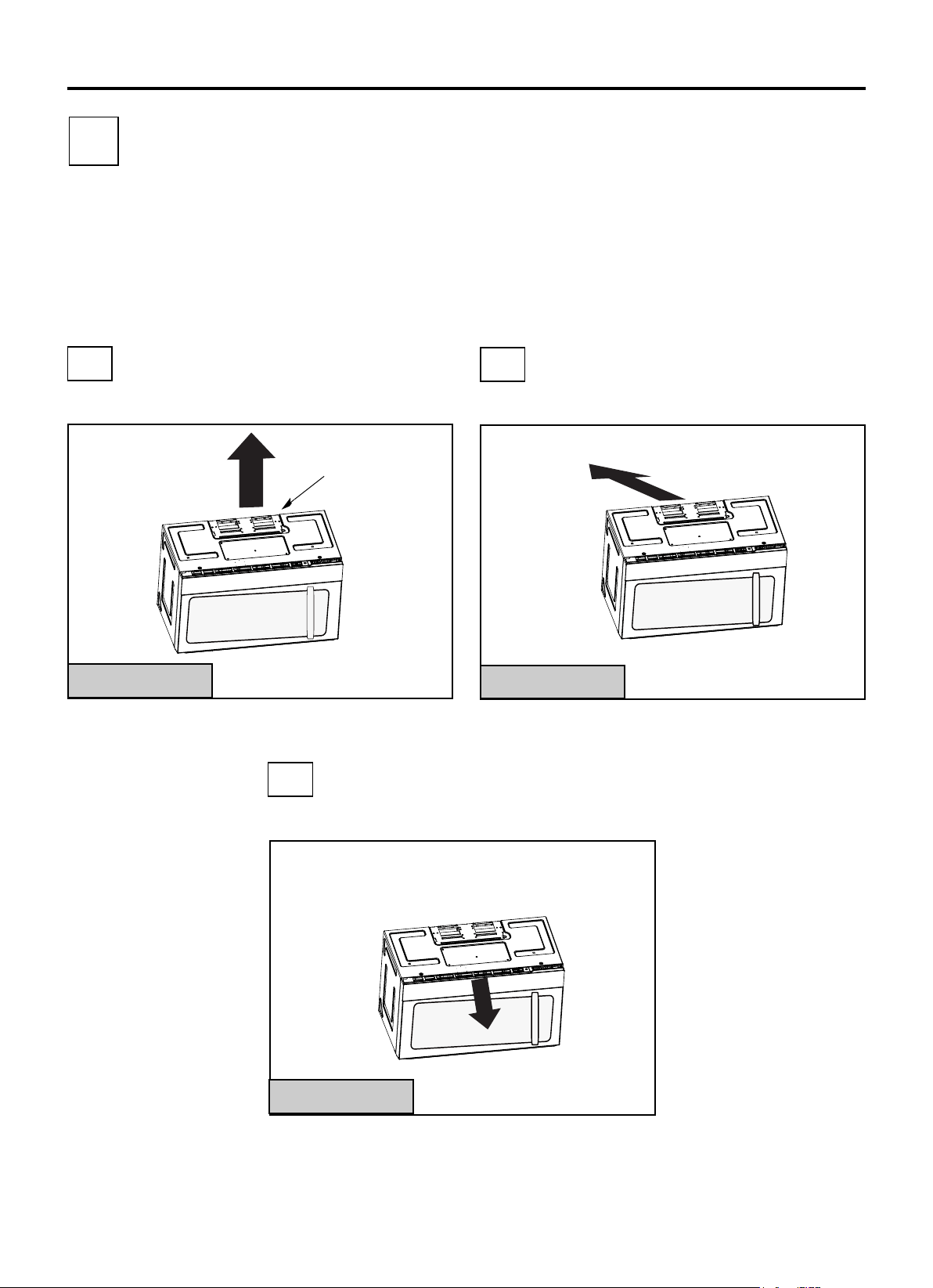
A
TIPOS DE INSTALACIÓN (Elija A, B o C)
Este horno de microondas se diseña para
adaptarse a los siguientes tres tipos de ventilación:
A. Escape Superior Exterior (Conducto Vertical)
B. Escape Exterior Trasera (Conducto Horizontal)
C. Recirculación (Sin Conductos de Ventilación)
NOTA: Este horno de microondas se envía
ensamblado para la Recirculación. Elija el tipo
de ventilación que desea para su instalación y
continúe con la sección correspondiente.
ESCAPE SUPERIOR
EXTERIOR (CONDUCTO
VERTICAL)
ESCAPE EXTERIOR
TRASERA (CONDUCTO
HORIZONTAL)
RECIRCULACIÓN
(SIN CONDUCTOS DE
VENTILACIÓN)
Consulte la página 12
Los modelos se envían
para el escape de
recirculación. Estos
modelos están
equipados con un filtro
de carbón desechable
para ayudar a eliminar el
humo y los olores.
Adaptador en
Posición para el
Escape Superior
Exterior
2
B
C
El Adaptador Debe
Moverse hacia atrás
para el Escape
Trasero Exterior
Consulte la página 16
Consulte la página 20
Instrucciones de Instalación
NOTA: Lea las siguientes dos páginas solo si planea ventilar su
escape hacia el exterior. Si desea recircular el aire de regreso
dentro de la habitación, consulte la página 20.
ES-9
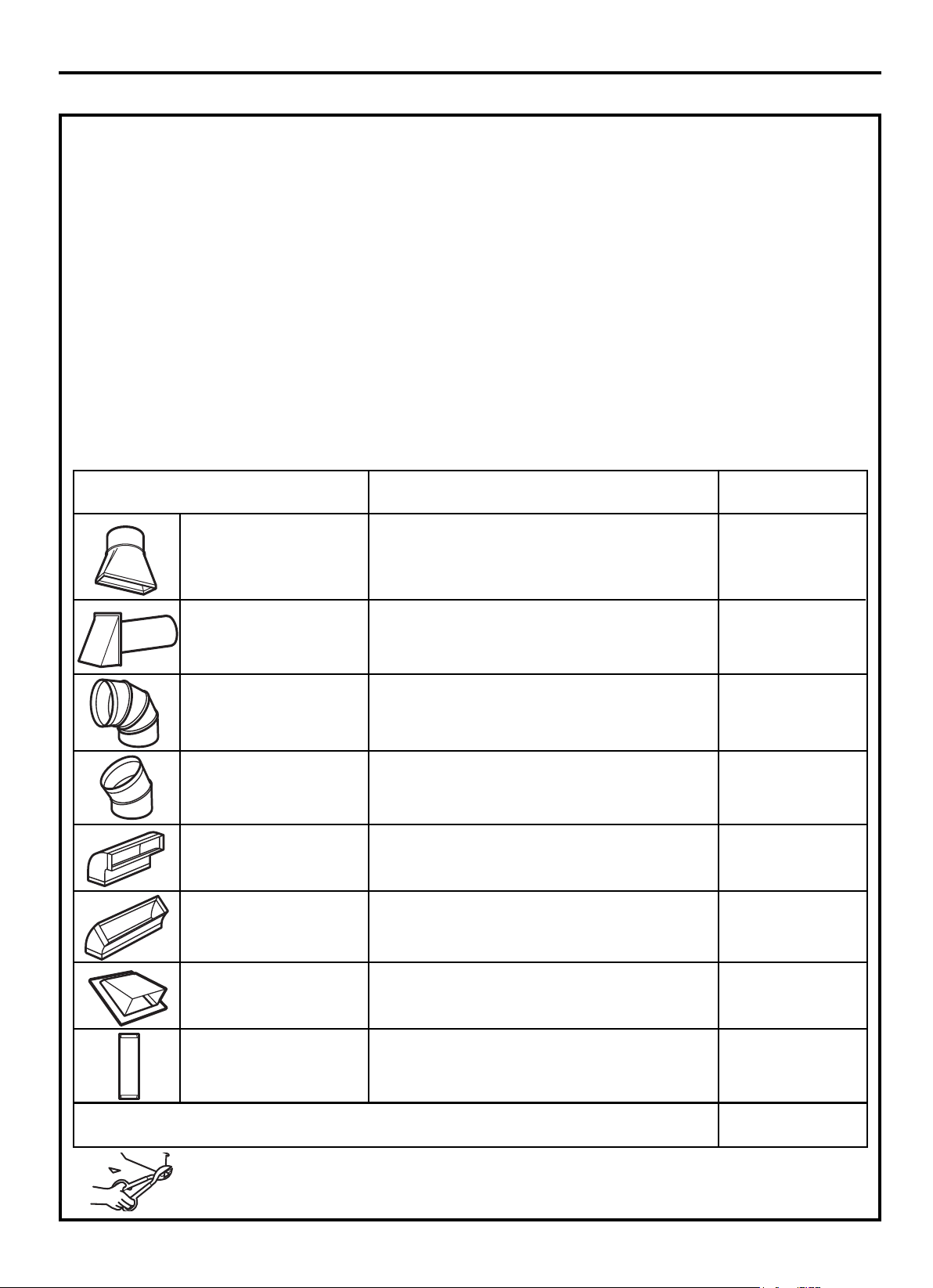
LONGITUD
EQUIVALENTE
NÚMERO
UTILIZADO
LONGITUD
EQUIVALENTE
PIEZAS DE CONDUCTO
x
=
5 Ft. (1,5 m) x ( ) =
Ft. o m
Adaptador de Transición
de Rectangular a
Redondo*
Tapa de Pared 40 Ft. (12,2 m) x ( ) =
Codo de 90º 10 Ft. (3 m) x ( ) =
Codo de 45º 5 Ft. (1,5 m) x ( ) =
Codo de 90º 25 Ft. (7,6 m) x ( ) =
Codo de 45º 5 Ft. (1,5 m) x ( ) =
Tapa de Techo 24 Ft. (7,3 m) x ( ) =
1 Ft. (0,3 m) x ( ) =
Conducto Recto de
6" (15,2 cm) Redondo
o 3¼"×10" (8,2×25,4 cm
Rectangular)
Conductos Totales =
Las longitudes equivalentes de las piezas de conductos se basan
en pruebas reales y reflejan los requisitos para un buen
rendimiento de ventilación con cualquier campana de ventilación.
* IMPORTANTE: Si se usa un adaptador de transición
de rectangular a redondo, las esquinas inferiores del
amortiguador deberán cortarse para que sea
conforme, con las tijeras de hojalatero, a fin de
permitir el libre movimiento del amortiguador.
NOTA: Si necesita instalar conductos, preste atención a que
la longitud total del conducto de 3
1
/
4
"×10" (8,2×25,4 cm)
rectangular o 5" (12,7 cm) de diámetro/6" (15,2 cm) de
diámetro del conducto redondo no debe exceder los 120
pies equivalentes (36,5 m).
La ventilación exterior necesita un CONDUCTO DE ESCAPE
EXTERIOR. Lea atentamente el siguiente contenido.
NOTA: Es importante que la ventilación sea instalada a
través de la ruta más directa y con la menor cantidad de
codos posible. Así se puede asegurar una ventilación clara
del escape y ayudar a prevenir los obstáculos. Por otro lado,
asegúrese de que las compuertas giren libremente y que
nada esté bloqueando los conductos.
Conexión del escape:
El adaptador de escape ha sido diseñado para acoplarse con
un conducto rectangular estándar de 3
1
/
4
"×10" (8,2×25,4 cm).
En caso de requerir un conducto redondo, se debe usar un
adaptador de transición de rectangular a redondo. Es
aplicable un conducto de 5" (12,7 cm)/6" (15,2 cm) de
diámetro.
Longitud máxima del conducto:
Para asegurar el movimiento fluido del aire, la longitud total del
conducto de 3
1
/
4
"×10" (8,2×25,4 cm) rectangular o 5" (12,7 cm)
de diámetro/6" (15,2 cm) de diámetro del conducto redondo no
debe exceder los 120 pies equivalentes (36,5 m).
Los codos, transiciones, tapas de paredes y
techos, etc., presentan una resistencia adicional al flujo de
aire y son equivalentes a una sección de conducto recto que
es más larga que su tamaño físico real. Por lo tanto, al calcular
la longitud total del conducto, hay que sumar las longitudes
equivalentes de todas las transiciones y adaptadores más la
longitud de todas las secciones del conducto recto. La
siguiente tabla le muestra el método de calcular la longitud
total equivalente de los conductos utilizando los pies
aproximados de longitud equivalente de algunos conductos
típicos.
Instrucciones de Instalación
INSTRUCCIONES DE INSTALACIÓN PARA CONDUCTO DE ESCAPE EXTERIOR
ES-10
Ft. o m
Ft. o m
Ft. o m
Ft. o m
Ft. o m
Ft. o m
Ft. o m
Ft. o m
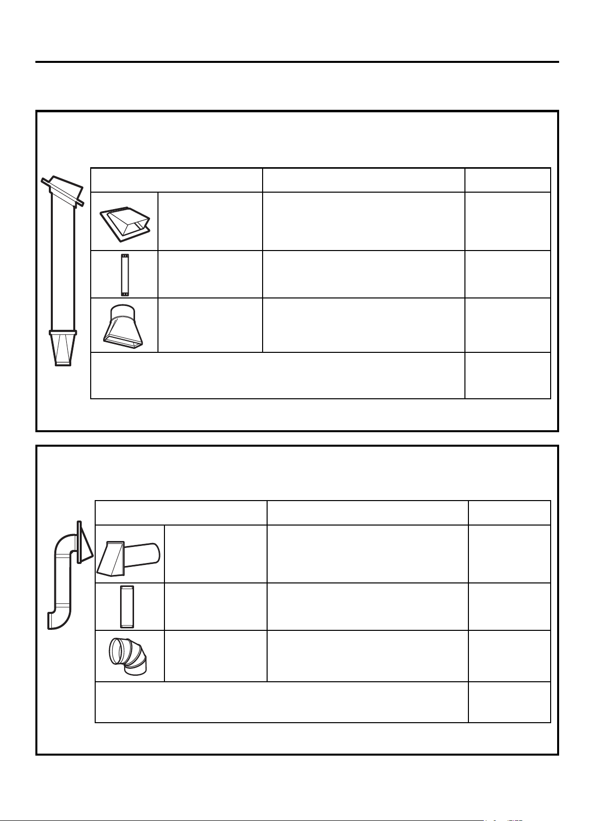
LONGITUD
EQUIVALENTE
NÚMERO
UTILIZADO
LONGITUD
EQUIVALENTE
PIEZAS DE CONDUCTO
x =
Tapa de Techo 24 Ft. (7,3 m) x (1) = 24 Ft. (7,3 m)
x (1) = 12 Ft. (3,6 m)
12 Pies (3,6 m)
Conducto Recto
(6"/15,2 cm Redondo)
5 Ft. (1,5 m) x (1) = 5 Ft. (1,5 m)
Adaptador de
Transición de
Rectangular a
Redondo*
Las longitudes equivalentes de las piezas de conductos se
basan en pruebas reales y reflejan los requisitos para un
buen rendimiento de ventilación con cualquier campana de
ventilación.
Longitud Total = 41 Ft. (12,4 m)
NOTA: Para el escape trasero, debe tener cuidado de alinear el escape con el espacio entre los montantes, o se debe
preparar la pared mientras se construye dejando suficiente espacio entre los montantes de la pared para acomodar el
escape.
* IMPORTANTE: Si se usa un adaptador de transición de rectangular a redondo, las esquinas inferiores del
amortiguador deberán cortarse para que sea conforme, con las tijeras de hojalatero, a fin de permitir el libre
movimiento del amortiguador.
ESCAPE SUPERIOR EXTERIOR (SOLO EJEMPLO)
El siguiente cuadro presenta un ejemplo de una posible instalación de conductos.
x =
Tapa de Pared
40 Ft. (12,2 m)
(1) = 40 Ft. (12,2 m)
x (1) = 3 Ft. (0,9 m)
3 Ft. (0,9 m)
Codo de 90º 10 Ft. (3 m) x (2) = 20 Ft. (6 m)
Las longitudes equivalentes de las piezas de conductos se basan
en pruebas reales y reflejan los requisitos para un buen
rendimiento de ventilación con cualquier campana de ventilación.
Instrucciones de Instalación
ES-11
LONGITUD
EQUIVALENTE
NÚMERO
UTILIZADO
LONGITUD
EQUIVALENTE
PIEZAS DE CONDUCTO
12 Ft. (3,6 m)
ESCAPE EXTERIOR TRASERO (SOLO EJEMPLO)
El siguiente cuadro presenta un ejemplo de una posible instalación de conductos.
Longitud Total = 63 Ft. (19,1 m)
3 Pies Conducto Recto
(3¼"×10"/8,2×25,4 cm
Rectangular)
CONDUCTO DE ESCAPE EXTERIOR
x
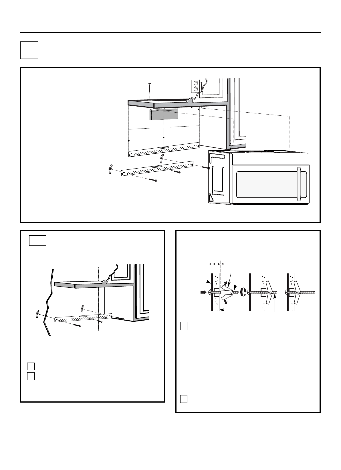
Ubique la placa de montaje contra la pared e
inserte las alas de fiador en los orificios de la
pared para instalar la placa.
NOTA: Antes de apretar los tornillos de fiador y el
tornillo para madera, asegúrese de que la parte
inferior de la placa de montaje tenga contacto con
la parte inferior de la Plantilla de la pared trasera
cuando se empuje contra la pared y que la placa
esté debidamente centrada debajo del gabinete.
PRECAUCIÓN: Tenga cuidado de no pillarse los
dedos entre la parte trasera de la placa de montaje
y la pared.
4
Apriete todos los tornillos. Extraiga la placa de la
pared para ayudar a apretar los tornillos.
3
FIJAR LA PLACA DE
MONTAJE A LA PARED
A1.
Fije la placa a la pared con tornillos de fiador.
Se debe utilizar al menos un tornillo para madera
para fijar la placa a un montante de la pared.
Retire las alas de fiador desde los tornillos.
Inserte los tornillos en la placa de montaje a
través de los orificios designados para entrar en
el panel de yeso y vuelva a fijar las alas de fiador
a
3
/
4
" (19 mm) en cada tornillo.
1
PERSPECTIVA DE
INSTALACIÓN
A1. Fijación de la Placa de Montaje a la
Pared
A2. Preparación del Gabinete Superior
A3. Adaptación del Ventilador de
Microondas para el Escape Exterior
Trasero
A4. Revisión del Funcionamiento del
Amortiguador
A5. Montaje del Horno de Microondas
A6. Ajuste del Adaptador de Escape
A7. Conexión de Conductos
NOTAS IMPORTANTES:
Pared
Placa de
Montaje
Espacio para Tornillos Más
que el Espesor de la Pared
Extremo de Tornillo
Tornillo de
Fiador
Alas de Fiador
Para usar los tornillos de fiador:
Instrucciones de Instalación
2
•
Asegúrese de que los tornillos del
motor del ventilador y la placa del
ventilador estén firmemente
apretados cuando se vuelvan a
instalar. Así se puede ayudar a
evitar vibraciones excesivas.
Confirme que el cableado del
motor se ha enrutado y
asegurado de manera adecuada,
y que los cables no están
pellizcados.
•
12"
4"
NOTA: ES MUY IMPORTANTE LEER Y SEGUIR LAS
INDICACIONES EN LAS INSTRUCCIONES DE INSTALACIÓN
ANTES DE PROCEDER CON ESTA PLANTILLA DE PARED
TRASERA.
Esta Plantilla de Pared Trasera sirve para colocar la placa de
montaje inferior y la salida de escape horizontal.
1. Use un nivel para revisar si la plantilla está posicionada con
precisión.
2. Sitúe y marque al menos un montante en el lado izquierdo o
derecho de la línea central.
NOTA: Es importante usar al menos un tornillo para madera
firmemente montado en un montante para sostener el peso del horno
de microondas. Marque dos posiciones adicionales, que deben ser
uniformemente espaciadas, para los tornillos de fiador suministrados.
3. Perfore orificios en las posiciones marcadas. Perfore un orificio
de 3/16" para tornillos para madera donde haya un montante.
Para los orificios que no se alinean con un montante, perfore
orificios de 5/8" para tornillos de fiador.
NOTA: NO INSTALE LA PLACA DE MONTAJE EN ESTE
MOMENTO.
4. Retire la plantilla desde la pared trasera.
5. Revise el manual de Instrucciones de Instalación para conocer
su situación de instalación.
Ubique y marque los orificios para alinearlos con los
orificios en la placa de montaje.
IMPORTANTE:
UBIQUE AL MENOS UN MONTANTE EN CUALQUIER
LADO DE LA LÍNEA CENTRAL.
MARQUE LA UBICACIÓN PARA 2 TORNILLOS DE
FIADOR ADICIONALES, QUE DEBEN SER
UNIFORMEMENTE ESPACIADOS, EN EL ÁREA DE LA
PLACA DE MONTAJE.
Recorte la plantilla de la pared trasera a lo largo de la línea punteada.
Da
rlevuelt
a
a
la
ho
ja
pa
ra
co
ns
ul
tarla
ver
sión
en
Espa
ñol.
IMPORTANTE:
UBIQUE AL MENOS UN MONTANTE EN CUALQUIER LADO DE LA LÍNEA
CENTRAL.
MARQUE LA UBICACIÓN PARA 2 TORNILLOS DE FIADOR ADICIONALES,
QUE DEBEN SER UNIFORMEMENTE ESPACIADOS, EN EL ÁREA DE LA
PLACA DE MONTAJE.
Recorte la plantilla de la pared trasera a lo largo de
la línea punteada.
3/8" HASTA EL BORDE
ES-12
A
ESCAPE SUPERIOR EXTERIOR (Conducto Vertical)
F. CORTE PARA EL ESCAPE EXTERIOR
HORIZONTAL
CORTE EL ORIFICIO A TRAVÉS DE LA PARED TRASERA
PARA EL ADAPTADOR DE ESCAPE
PRECAUCIÓN - SI EL ADAPTADOR DE ESCAPE SE SITÚA FUERA DE LA
DIMENSIÓN RECOMENDADA, LOS VAPORES GRASOS SE DESCARGARÁN
EN LA ESTRUCTURA DE LA CASA.
30" ANCHO MÍNIMO DEMANDADO
PLANTILLA DE LA PARED TRASERA
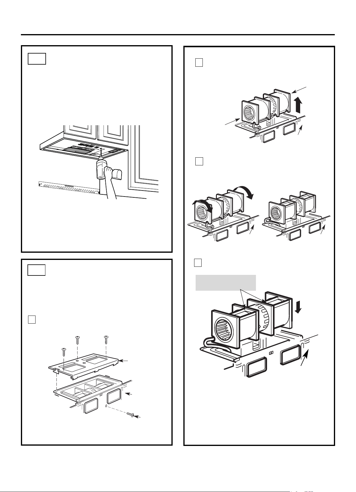
USO DE LA PLANTILLA DEL
GABINETE SUPERIOR PARA
PREPARAR EL GABINETE
SUPERIOR
Es necesario perforar orificios para los tornillos de
soporte superiores, un orificio de largo suficiente para
que pase el cable de alimentación y un corte de largo
suficiente para el adaptador de escape.
A2.
•
Lea las instrucciones en la PLANTILLA DEL
GABINETE SUPERIOR.
Péguelo debajo del gabinete superior.
Perfore los orificios de acuerdo con las instrucciones
de la PLANTILLA DEL GABINETE SUPERIOR.
•
•
PRECAUCIÓN: Use las gafas de protección al
perforar orificios en la parte inferior del gabinete.
Instrucciones de Instalación
A3.
Retire el tornillo que sujeta la placa del
ventilador al horno. Retire y guarde el tornillo
que sujeta el motor del ventilador al horno.
Placa del Ventilador
Tornillo del
Motor del
Ventilador
Espalda del Horno
de Microondas
2
Retire atentamente la unidad del ventilador.
Los cables se extenderán lo suficiente para
permitirle ajustar la unidad del ventilador.
1
ADAPTACIÓN DEL
VENTILADOR DE
MICROONDAS PARA EL
ESCAPE SUPERIOR
EXTERIOR
3
Espalda del
Horno de
Microondas
Gire la unidad del ventilador 90° para que las
aberturas de las aspas del ventilador queden
hacia afuera de la parte superior del horno.
Espalda del
Horno de
Microondas
Espalda del
Horno de
Microondas
Reponga la unidad del ventilador en la abertura.
DESPUÉS: Aberturas de
Aspas del Ventilador
Mirando Hacia Arriba
PRECAUCIÓN: No tire ni estire los cables de
la unidad del ventilador. Compruebe que los
cables no estén pellizcados y que estén
debidamente asegurados.
4
Coloque el horno de microondas en posición
vertical, con la parte superior de la unidad
hacia arriba.
ES-13
Extremo B
Extremo A
Espalda del Horno
de Microondas
Antes del Giro Después del Giro
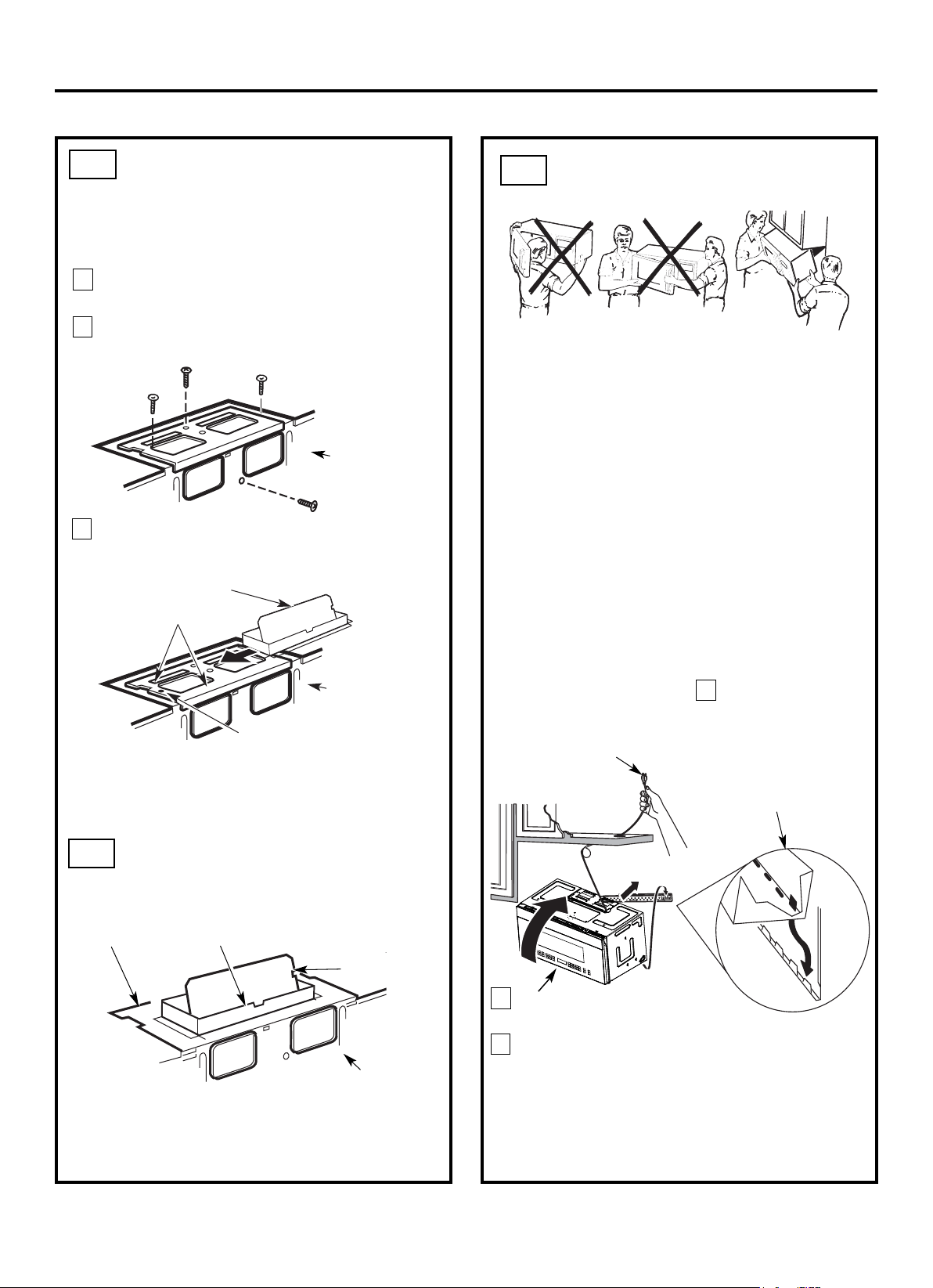
3
INSTALACIÓN DEL HORNO
DE
MICROONDAS
PARA FACILITAR LA INSTALACIÓN Y GARANTIZAR
LA SEGURIDAD PERSONAL, SE RECOMIENDA QUE
LA INSTALACIÓN DEL PRODUCTO SEA REALIZADA
POR DOS PERSONAS.
IMPORTANTE: No sujete ni use la manija o el
protector térmico durante la instalación. No retire los
espaciadores de cartón entre el protector térmico y
la puerta.
NOTA: Si su gabinete es metálico, use el ojal de nilón
alrededor del orificio del cable de alimentación para
evitar que se corte el cable.
NOTA: Es recomendable usar bloques de relleno si el
frente del gabinete cuelga debajo del estante inferior del
gabinete.
IMPORTANTE: En caso de no usar bloques de
relleno, se pueden producir daños en la caja debido
a un apriete excesivo de los tornillos.
2
Gire el frente del horno
hacia arriba para que se encuentre
contra la parte inferior del gabinete.
Inserte un tornillo autoalineador a través de uno de los
orificios del gabinete superior. Asegure temporalmente
el horno por medio de girar el tornillo al menos dos
vueltas completas después de que las roscas se hayan
acoplado. (Será apretada por completo más tarde.)
Asegúrese de mantener apretado el cable de
alimentación. Tenga cuidado de no pellizcar el cable,
especialmente cuando lo monte al ras de la parte
inferior del gabinete.
NOTA: Al montar el horno de
microondas, pase el cable de
alimentación a través del
orificio en la parte inferior del
gabinete superior. Manténgalo
ajustado por medio de los
pasos 1 - 3. No pellizque el
cable ni levante el horno por
tirar del cable.
Levante el
microondas, inclínelo
hacia adelante y
enganche las ranuras
en el borde inferior
trasero en las cuatro
pestañas inferiores de
la placa de montaje.
1
Amortiguador
Espalda del
Horno de
Microondas
•
Asegúrese de quitar la cinta que asegura el
amortiguador y que el amortiguador pueda girar
fácilmente antes de montar el horno.
Tendrá que realizar ajustes para asegurar una alineación
adecuada con el conducto de escape de su casa después
de haber instalado el microondas.
•
A3.
ADAPTACIÓN DEL
VENTILADOR DE
MICROONDAS PARA EL
ESCAPE SUPERIOR
EXTERIOR
5
Espalda del
Horno de
Microondas
6
7
Guía
Adaptador
Empuje firmemente hasta que esté en las
pestañas de bloqueo.
Asegúrese de que la bisagra del amortiguador
esté instalada de modo que el amortiguador oscile
de manera flexible.
Fije el adaptador de escape a la parte superior de la
placa del ventilador deslizándolo en las guías de la
placa del ventilador.
A4.
A5.
Instrucciones de Instalación
ES-14
Reponga la placa del ventilador con los tornillos
retirados en el Paso 1. Asegúrese de que los tornillos
estén apretados.
Fije la unidad del ventilador al horno con el tornillo
retirado en el Paso 1. Asegúrese de que el tornillo
esté apretado.
Espalda del Horno
de Microondas
Pestaña de bloqueo
COMPROBACIÓN DEL
FUNCIONAMIENTO
CORRECTO DEL
AMORTIGUADOR
Placa del
Ventilador
Adaptador
de Escape
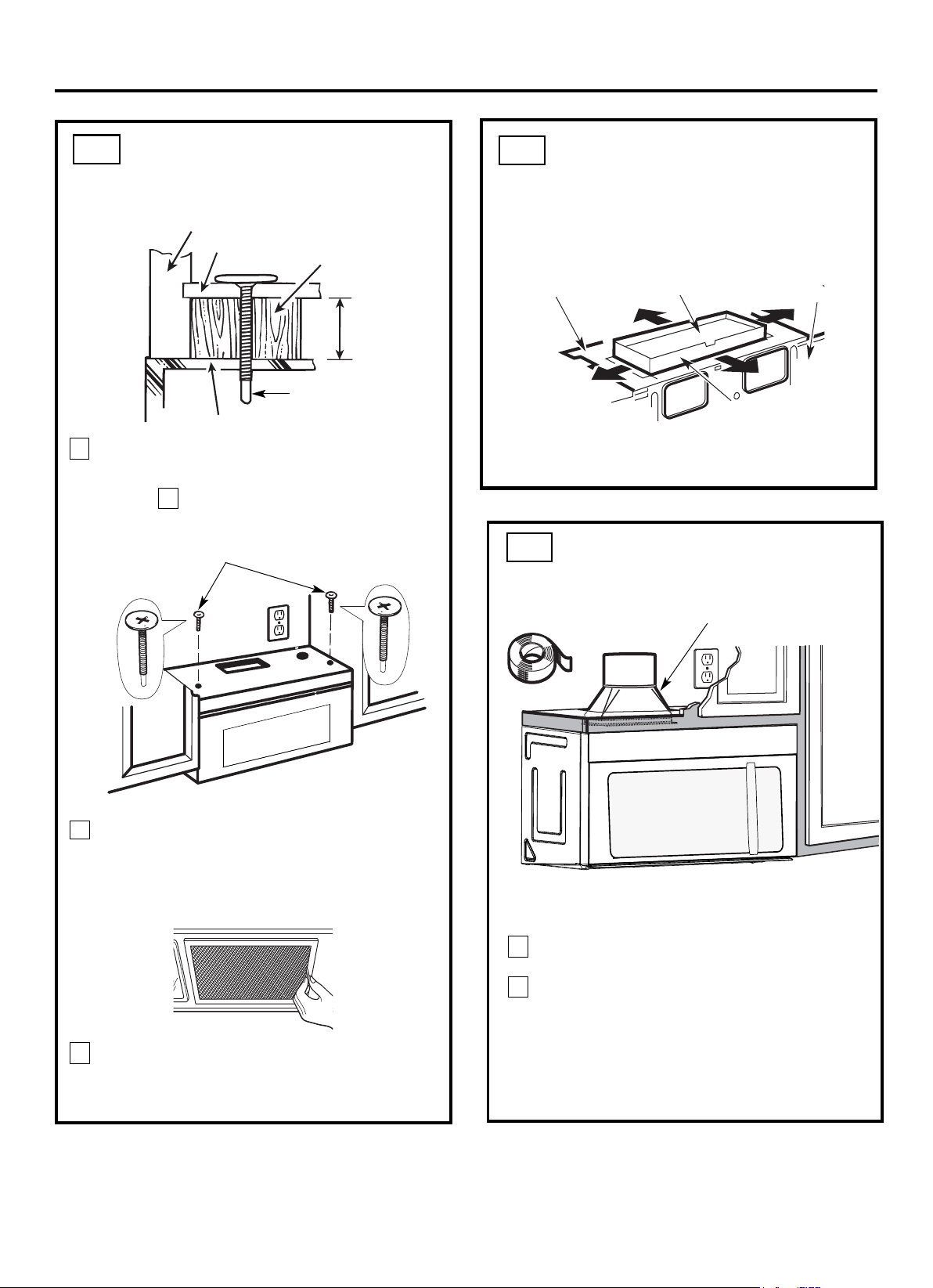
4 Fije el horno de microondas al gabinete superior.
8
7
Frente del Gabinete
Estante de la Parte Inferior del Gabinete
Apriete los dos tornillos exteriores a la parte
superior del horno de microondas. (Al apretar los
tornillos, sostenga el horno de microondas en su
posición contra la pared y el gabinete superior.)
Bloque de Relleno
Parte Superior del Horno de Microondas
Equivalente a
la Profundidad
de la Ranura
del Gabinete
Instale los filtros de grasa. Consulte el Uso y
Cuidado adjunto con el horno de microondas.
Instrucciones de Instalación
AJUSTE DEL ADAPTADOR
DE ESCAPE
Abra el gabinete superior y ajuste el adaptador de
escape para conectarlo al conducto de la casa.
Espalda del
Horno de
Microondas
Para el Ajuste de Adelante
hacia Atrás o de Lado a
Lado, Deslice el Adaptador
de Escape según sea
Necesario
Placa del Ventilador
Amortiguador
Tornillo Autoalineador
5
INSTALACIÓN DEL HORNO
DE MICROONDAS
(continuar)
A6.
A5.
CONEXIÓN DE CONDUCTOS
1
2
Tienda el conducto de casa hacia abajo para
conectarlo al adaptador de escape.
A7.
Use cinta para conductos de calefacción resistentes
a alta temperatura para sellar las uniones de los
conductos.
ES-15
Conducto de Casa
Inserte el segundo tornillo
autoalineador a través del orificio
restante del gabinete superior.
Gire el tornillo dos vueltas completas.
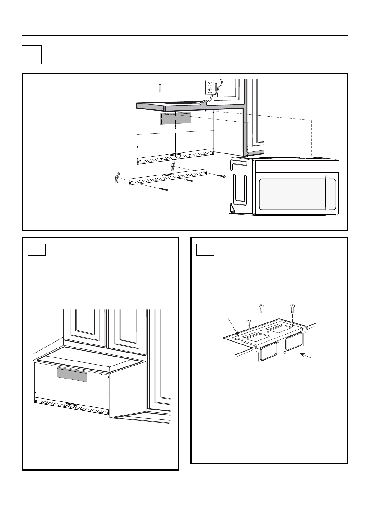
PERSPECTIVA DE
INSTALACIÓN
B1. Preparación de la Pared Trasera
B2. Eliminación de la Placa del
Ventilador
B3. Fijación de la Placa de Montaje a
la Pared
B4. Preparación del Gabinete Superior
B5. Ajuste del Ventilador
B6. Instalación del Horno de
Microondas
NOTAS IMPORTANTES:
•
•
Asegúrese de que los tornillos del
motor del ventilador y la placa del
ventilador estén firmemente
apretados cuando se vuelvan a
instalar. Así se puede ayudar a
evitar vibraciones excesivas.
Confirme que el cableado del
motor se ha enrutado y asegurado
de manera adecuada, y que los
cables no están pellizcados.
Retire y guarde el tornillo que sujeta la placa del
ventilador al horno. Levante la placa del
ventilador.
Espalda del
Horno de
Microondas
Instrucciones de Instalación
PREPARACIÓN DE LA
PARED TRASERA PARA EL
ESCAPE EXTERIOR
TRASERO
B1.
Necesita cortar una apertura en la pared trasera
para el escape exterior.
•
Lea las instrucciones en la PLANTILLA DE LA PARED
TRASERA.
Péguelo a la pared trasera.
Corte la apertura de acuerdo con las instrucciones de la
PLANTILLA DE LA PARED TRASERA.
•
•
Placa del Ventilador
B2.
ELIMINACIÓN DE LA PLACA
DEL VENTILADOR
3/8" HASTA EL BORDE
PRECAUCIÓN - SI EL ADAPTADOR DE
ESCAPE SE SITÚA FUERA DE LA DIMENSIÓN
RECOMENDADA, LOS VAPORES GRASOS SE DESCARGARÁN
.EN LA ESTRUCTURA DE LA CASA
ANCHO MÍNIMO DEMANDADO "30
PLANTILLA DE LA PARED
TRASERA
NOTA: ES MUY IMPORTANTE LEER Y SEGUIR LAS INDICACIONES
EN LAS INSTRUCCIONES DE INSTALACIÓN ANTES DE PROCEDER
CON ESTA PLANTILLA DE PARED TRASERA.
Esta Plantilla de Pared Trasera sirve para colocar la placa de montaje
inferior y la salida de escape horizontal.
1. Use un nivel para revisar si la plantilla está posicionada con precisión.
2. Sitúe y marque al menos un montante en el lado izquierdo o derecho
de la línea central.
NOTA: Es importante usar al menos un tornillo para madera firmemente
montado en un montante para sostener el peso del horno de
microondas. Marque dos posiciones adicionales, que deben ser
uniformemente espaciadas, para los tornillos de fiador suministrados.
3. Perfore orificios en las posiciones marcadas. Perfore un orificio de
3/16" para tornillos para madera donde haya un montante. Para los
orificios que no se alinean con un montante, perfore orificios de 5/8"
para tornillos de fiador.
NOTA: NO INSTALE LA PLACA DE MONTAJE EN ESTE MOMENTO.
4. Retire la plantilla desde la pared trasera.
5. Revise el manual de Instrucciones de Instalación para conocer su
situación de instalación.
Ubique y marque los orificios para alinearlos con los orificios en la placa de
montaje.
IMPORTANTE:
UBIQUE AL MENOS UN MONTANTE EN CUALQUIER LADO DE LA LÍNEA
CENTRAL.
MARQUE LA UBICACIÓN PARA 2 TORNILLOS DE FIADOR ADICIONALES,
QUE DEBEN SER UNIFORMEMENTE ESPACIADOS, EN EL ÁREA DE LA
PLACA DE MONTAJE.
Ubique y marque los orificios para alinearlos con los orificios en la placa de montaje.
IMPORTANTE:
UBIQUE AL MENOS UN MONTANTE EN CUALQUIER LADO DE LA LÍNEA CENTRAL.
MARQUE LA UBICACIÓN PARA 2 TORNILLOS DE FIADOR ADICIONALES, QUE DEBEN SER
UNIFORMEMENTE ESPACIADOS, EN EL ÁREA DE LA PLACA DE MONTAJE.
Recorte la plantilla de la pared trasera a lo largo de la línea punteada.
Recorte la plantilla de la pared trasera a lo
largo de la línea punteada.
F. CORTE PARA EL ESCAPE
EXTERIOR HORIZONTAL
CORTE EL ORIFICIO A TRAVÉS DE LA PARED TRASERA PARA EL ADAPTADOR DE ESCAPE
12"
4"
Darle vuelta a la hoja para consultar la
versión en Español.
12"
4"
NOTA: ES MUY IMPORTANTE LEER Y SEGUIR LAS
INDICACIONES EN LAS INSTRUCCIONES DE INSTALACIÓN
ANTES DE PROCEDER CON ESTA PLANTILLA DE PARED
TRASERA.
Esta Plantilla de Pared Trasera sirve para colocar la placa de
montaje inferior y la salida de escape horizontal.
1. Use un nivel para revisar si la plantilla está posicionada con
precisión.
2. Sitúe y marque al menos un montante en el lado izquierdo o
derecho de la línea central.
NOTA: Es importante usar al menos un tornillo para madera
firmemente montado en un montante para sostener el peso del horno
de microondas. Marque dos posiciones adicionales, que deben ser
uniformemente espaciadas, para los tornillos de fiador suministrados.
3. Perfore orificios en las posiciones marcadas. Perfore un orificio de
3/16" para tornillos para madera donde haya un montante. Para
los orificios que no se alinean con un montante, perfore orificios
de 5/8" para tornillos de fiador.
NOTA: NO INSTALE LA PLACA DE MONTAJE EN ESTE
MOMENTO.
4. Retire la plantilla desde la pared trasera.
5. Revise el manual de Instrucciones de Instalación para conocer su
situación de instalación.
Ubique y marque los orificios para alinearlos con los orificios en
la placa de montaje.
IMPORTANTE:
UBIQUE AL MENOS UN MONTANTE EN CUALQUIER LADO
DE LA LÍNEA CENTRAL.
MARQUE LA UBICACIÓN PARA 2 TORNILLOS DE FIADOR
ADICIONALES, QUE DEBEN SER UNIFORMEMENTE
ESPACIADOS, EN EL ÁREA DE LA PLACA DE MONTAJE.
Recorte la plantilla de la pared trasera a lo largo de la línea punteada.
Da
rle
vu
elt
aa
la
ho
ja
pa
ra
co
nsultarla
versión
en
Españo
l.
Ubique y marque los orificios para alinearlos con los orificios en la
placa de montaje.
IMPORTANTE:
UBIQUE AL MENOS UN MONTANTE EN CUALQUIER LADO DE
LA LÍNEA CENTRAL.
MARQUE LA UBICACIÓN PARA 2 TORNILLOS DE FIADOR
ADICIONALES, QUE DEBEN SER UNIFORMEMENTE
ESPACIADOS, EN EL ÁREA DE LA PLACA DE MONTAJE.
Recorte la plantilla de la pared trasera a lo largo
de la línea punteada.
3/8" HASTA EL BORDE
ES-16
B
ESCAPE EXTERIOR TRASERA (Conducto Horizontal)
F. CORTE PARA EL ESCAPE EXTERIOR
HORIZONTAL
CORTE EL ORIFICIO A TRAVÉS DE LA PARED TRASERA
PARA EL ADAPTADOR DE ESCAPE
PRECAUCIÓN - SI EL ADAPTADOR DE ESCAPE SE SITÚA FUERA DE LA
DIMENSIÓN RECOMENDADA, LOS VAPORES GRASOS SE DESCARGARÁN
EN LA ESTRUCTURA DE LA CASA.
30" ANCHO MÍNIMO DEMANDADO
PLANTILLA DE LA PARED TRASERA
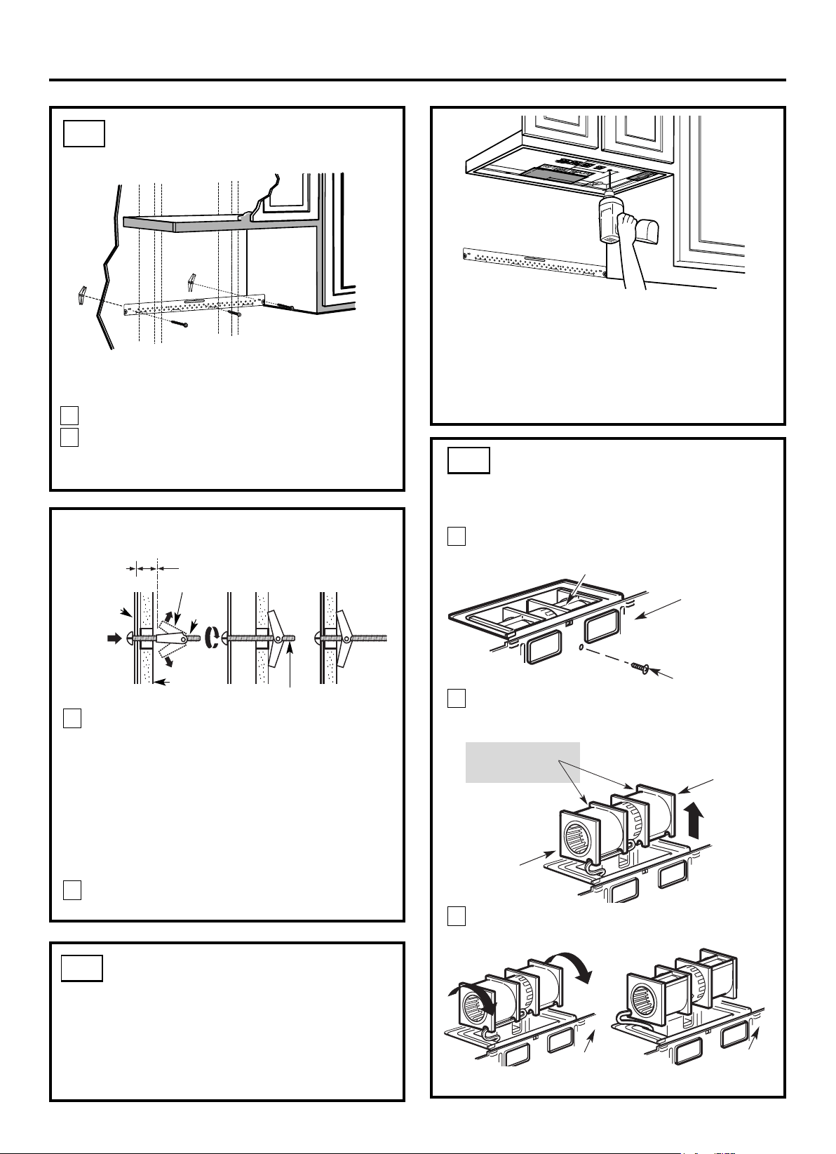
FIJAR LA PLACA DE
MONTAJE A LA PARED
B3.
•
Lea las instrucciones en la PLANTILLA DEL
GABINETE SUPERIOR.
Péguelo debajo del gabinete superior.
Perfore los orificios de acuerdo con las instrucciones
de la PLANTILLA DEL GABINETE SUPERIOR.
•
•
PRECAUCIÓN: Use las gafas de protección al
perforar orificios en la parte inferior del gabinete.
Pared
Placa de
Montaje
Espacio para Tornillos Más que
el Espesor de la Pared
Tornillo
de Fiador
Alas de Fiador
Para usar los tornillos de fiador:
Extremo de Tornillo
Instrucciones de Instalación
Fije la placa a la pared con tornillos de fiador.
Se debe utilizar al menos un tornillo para madera
para fijar la placa a un montante de la pared.
Retire las alas de fiador desde los tornillos.
Inserte los tornillos en la placa de montaje a través de
los orificios designados para entrar en el panel de yeso
y vuelva a fijar las alas de fiador a 3/4" (19 mm) en
cada tornillo.
1
2
Ubique la placa de montaje contra la pared e inserte
las alas de fiador en los orificios de la pared para
instalar la placa.
NOTA: Antes de apretar los tornillos de fiador y el
tornillo para madera, asegúrese de que la parte inferior
de la placa de montaje tenga contacto con la parte
inferior de la plantilla de la pared trasera cuando se
empuje contra la pared y que la placa esté debidamente
centrada debajo del gabinete.
PRECAUCIÓN: Tenga cuidado de no pillarse los dedos
entre la parte trasera de la placa de montaje y la pared.
Apriete todos los tornillos. Extraiga la placa de la
pared para ayudar a apretar los tornillos.
3
4
2
1
Retire y guarde el tornillo que sujeta el motor del
ventilador al horno.
ADAPTACIÓN DEL
VENTILADOR DE
MICROONDAS PARA EL
ESCAPE EXTERIOR TRASERO
B5.
Extremo B
Extremo A
Espalda del Horno de
Microondas
Motor del Ventilador
Tornillo del Motor
del Ventilador
Retire atentamente la unidad del ventilador. Los
cables se extenderán lo suficiente para permitirle
ajustar la unidad del ventilador.
Antes: Aberturas de
Aspas del Ventilador
Mirando Hacia
Adelante
USO DE LA PLANTILLA DEL
GABINETE SUPERIOR PARA
PREPARAR EL GABINETE
SUPERIOR
B4.
Necesita perforar agujeros para los tornillos de soporte
superiores y un agujero de largo suficiente para que pase
el cable de alimentación.
Espalda del
Horno de
Microondas
Gire la unidad del ventilador 90º
Espalda del
Horno de
Microondas
3
Antes del Giro Después del Giro
ES-17
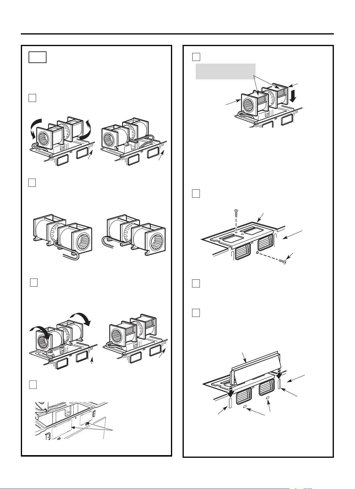
Conecte el adaptador de escape a la espalda
del horno deslizándolo en las guías en la parte
superior central de la espalda del horno.
DESPUÉS: Abertura de
Aspas del Ventilador
Mirando Hacia Atrás
Reponga la unidad del ventilador en la abertura.
Reponga la placa del ventilador en la posición
original con los tornillos apretados.
Gire la unidad del ventilador 90° para que las
aberturas de las aspas del ventilador queden hacia
afuera de la espalda del horno.
ADAPTACIÓN DEL
VENTILADOR DE
MICROONDAS PARA EL
ESCAPE EXTERIOR
TRASERO (continuar)
B5.
Gire la unidad del ventilador 180° en sentido
antihorario.
Antes del Giro Después del Giro
Retire atentamente los cables de las ranuras.
Desvíe los cables a través de las ranuras en el otro
lado de la unidad del ventilador.
Antes de la Desviación
Después de la Desviación
Cables Desviados por Lado
Derecho
Cables Desviados por Lado
Izquierdo
Espalda del
Horno de
Microondas
Espalda del
Horno de
Microondas
Placa del Ventilador
Tornillo del Motor
del Ventilador
Antes del Giro Después del Giro
Espalda del Horno
de Microondas
Extremo A
Extremo B
Espalda del Horno
de Microondas
Espalda del
Horno de
Microondas
PRECAUCIÓN: No tire ni estire los cables de
la unidad del ventilador. Compruebe que los
cables no estén pellizcados y que estén
debidamente asegurados.
NOTA: Las aberturas de escape de la
unidad del ventilador deben coincidir con
las aberturas de escape en la espalda del
horno de microondas.
Instrucciones de Instalación
Empuje firmemente hasta que esté en las
pestañas de bloqueo más bajo. Asegúrese de que
la bisagra del amortiguador esté instalada en la
parte superior y pueda oscilar de manera flexible.
Guía
Guía
Adaptador
Pestañas de Bloqueo
Espalda del
Horno de
Microondas
4
5
6
11
Espalda del
Horno de
Microondas
Placas de Troqueles:
Recorte todas las 4
pestañas de cada placa
de troqueles y retire los
troqueles metálicos para
facilitar el flujo de aire
trasero. Tenga cuidado
de quitar los bordes
afilados formados al
retirar las placas de
troqueles.
8
9
10
7
Retire las placas ciegas en la espalda de la unidad
con tijeras. (Para algunos modelos)
ES-18
Fije la unidad del ventilador al horno de
microondas con los tornillos originales.
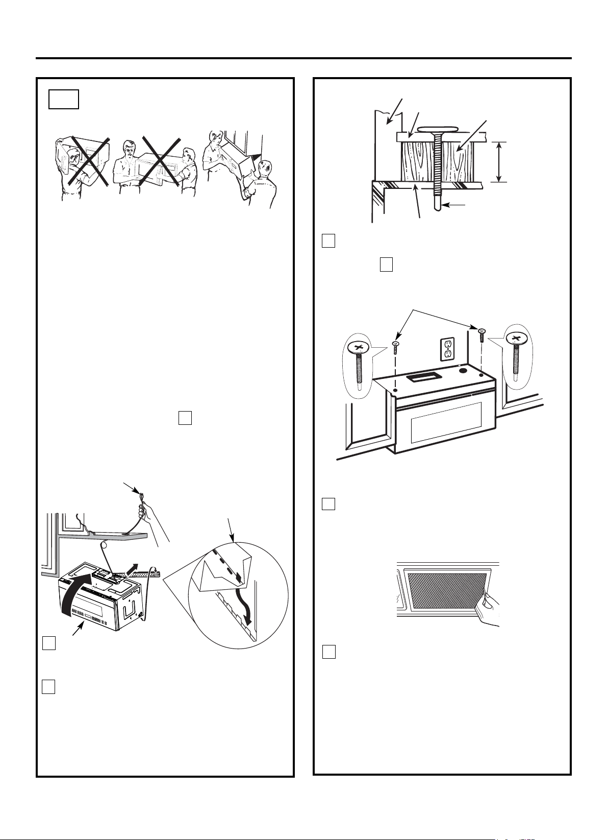
Fije el horno de microondas al gabinete superior.
Instrucciones de Instalación
3
INSTALACIÓN DEL HORNO
DE MICROONDAS
B6.
PARA FACILITAR LA INSTALACIÓN Y GARANTIZAR
LA SEGURIDAD PERSONAL, SE RECOMIENDA
QUE LA INSTALACIÓN DEL PRODUCTO SEA
REALIZADA POR DOS PERSONAS.
IMPORTANTE: No sujete ni use la manija o el
protector térmico durante la instalación. No retire
los espaciadores de cartón entre el protector
térmico y la puerta.
NOTA: Si su gabinete es metálico, use el ojal de nilón
alrededor del orificio del cable de alimentación para
evitar que se corte el cable.
NOTA: Es recomendable usar bloques de relleno si el
frente del gabinete cuelga debajo del estante inferior
del gabinete.
IMPORTANTE: En caso de no usar bloques de
relleno, se pueden producir daños en la caja
debido a un apriete excesivo de los tornillos.
Inserte un tornillo autoalineador a través de uno de
los orificios del gabinete superior. Asegure
temporalmente el horno por medio de girar el tornillo
al menos dos vueltas completas después de que
las roscas se hayan acoplado. (Será apretada por
completo más tarde.) Asegúrese de mantener
apretado el cable de alimentación. Tenga cuidado
de no pellizcar el cable, especialmente cuando lo
monte al ras de la parte inferior del gabinete.
8
7
5
Frente del Gabinete
Estante de la Parte
Inferior del Gabinete
Apriete los dos tornillos a la parte superior del
horno de microondas. (Al apretar los tornillos,
sostenga el horno de microondas en su posición
contra la pared y el gabinete superior.)
Bloque de Filtro
Parte Superior del Horno de Microondas
Equivalente a
la Profundidad
de la Ranura
del Gabinete
Instale los filtros de grasa. Consulte el Uso y
Cuidado adjunto con el horno de microondas.
Tornillo Autoalineador
4
2
Gire el frente del horno hacia
arriba para que se encuentre
contra la parte inferior del
gabinete.
NOTA: Al montar el horno de
microondas, pase el cable de
alimentación a través del
orificio en la parte inferior del
gabinete superior.
Manténgalo ajustado por
medio de los pasos 1-3. No
pellizque el cable ni levante
el horno por tirar del cable.
Levante el
microondas,
inclínelo hacia
adelante y
enganche las
ranuras en el borde
inferior trasero en
las cuatro pestañas
inferiores de la
placa de montaje.
1
ES-19
Inserte el segundo tornillo
autoalineador a través del orificio
restante del gabinete superior.
Gire el tornillo dos vueltas
completas.
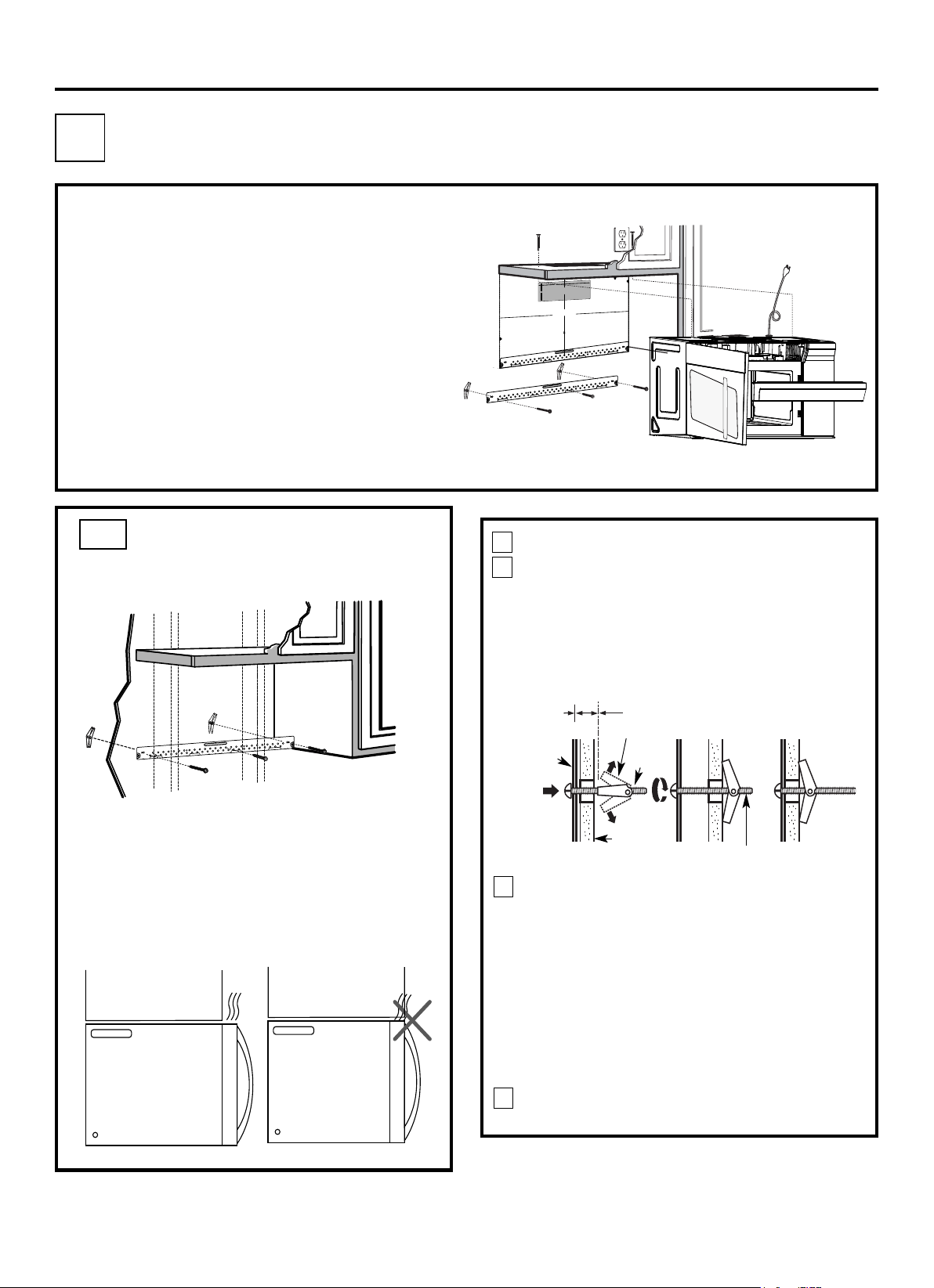
PERSPECTIVA DE INSTALACIÓN
Instrucciones de Instalación
Ubique la placa de montaje contra la pared e
inserte las alas de fiador en los orificios de la
pared para instalar la placa.
NOTA: Antes de apretar los tornillos de fiador y el
tornillo para madera, asegúrese de que la parte
inferior de la placa de montaje tenga contacto con la
parte inferior de la Plantilla de la pared trasera cuando
se empuje contra la pared y que la placa esté
debidamente centrada debajo del gabinete.
PRECAUCIÓN: Tenga cuidado de no pillarse los
dedos entre la parte trasera de la placa de montaje y
la pared.
4
Apriete todos los tornillos. Extraiga la placa de la
pared para ayudar a apretar los tornillos.
3
FIJAR LA PLACA DE
MONTAJE A LA PARED
C1.
Fije la placa a la pared con tornillos de fiador.
Se debe utilizar al menos un tornillo para madera para
fijar la placa a un montante de la pared.
Retire las alas de fiador desde los tornillos.
Inserte los tornillos en la placa de montaje a
través de los orificios designados para entrar en
el panel de yeso y vuelva a fijar las alas de
fiador a
3
/
4
" (19 mm) en cada tornillo.
1
Pared
Placa de
Montaje
Espacio para Tornillos Más
que el Espesor de la Pared
Extremo de Tornillo
Tornillo
de Fiador
Alas de Fiador
Para usar los tornillos de fiador:
2
C1. Fijación de la Placa de Montaje a la Pared
C2. Preparación del Gabinete Superior
C3. Inspección de la Placa del Ventilador
C4. Instalación del Horno de Microondas
C5. Instalación o Sustitución del Filtro de Carbón
GabineteGabinete
NOTA: Si la profundidad del gabinete, incluidas las puertas
del gabinete, es superior a 13", pues la unidad
debe estar separada de la pared por medio de
materiales adecuados que soporten 150 libras para
permitir la entrada/salida de aire de ventilación
superior de manera adecuada.
ES-20
12"
NOTA: ES MUY IMPORTANTE LEER Y SEGUIR LAS
INDICACIONES EN LAS INSTRUCCIONES DE
INSTALACIÓN ANTES DE PROCEDER CON ESTA
PLANTILLA DE PARED TRASERA.
Esta Plantilla de Pared Trasera sirve para colocar la
placa de montaje inferior y la salida de escape
horizontal.
1. Use un nivel para revisar si la plantilla está
posicionada con precisión.
2. Sitúe y marque al menos un montante en el lado
izquierdo o derecho de la línea central.
NOTA: Es importante usar al menos un tornillo para
madera firmemente montado en un montante para
sostener el peso del horno de microondas. Marque dos
posiciones adicionales, que deben ser uniformemente
espaciadas, para los tornillos de fiador suministrados.
3. Perfore orificios en las posiciones marcadas. Perfore
un orificio de 3/16" para tornillos para madera donde
haya un montante. Para los orificios que no se
alinean con un montante, perfore orificios de 5/8"
para tornillos de fiador.
NOTA: NO INSTALE LA PLACA DE MONTAJE EN
ESTE MOMENTO.
4. Retire la plantilla desde la pared trasera.
5. Revise el manual de Instrucciones de Instalación
para conocer su situación de instalación.
Ubique y marque los orificios para alinearlos con los orificios
en la placa de montaje.
IMPORTANTE:
UBIQUE AL MENOS UN MONTANTE EN CUALQUIER
LADO DE LA LÍNEA CENTRAL.
MARQUE LA UBICACIÓN PARA 2 TORNILLOS DE
FIADOR ADICIONALES, QUE DEBEN SER
UNIFORMEMENTE ESPACIADOS, EN EL ÁREA DE LA
PLACA DE MONTAJE.
Ubique y marque los orificios para alinearlos con los orificios en la placa
de montaje.
IMPORTANTE:
UBIQUE AL MENOS UN MONTANTE EN CUALQUIER LADO DE LA
LÍNEA CENTRAL.
MARQUE LA UBICACIÓN PARA 2 TORNILLOS DE FIADOR
ADICIONALES, QUE DEBEN SER UNIFORMEMENTE ESPACIADOS,
EN EL ÁREA DE LA PLACA DE MONTAJE.
Recorte la plantilla de la pared trasera a lo largo de la línea punteada.
vDearrslieóvnueenltaEsaplaañohol.japaraconsultarla
3/8" HASTA EL BORDE
Recorte la plantilla de la pared trasera a lo largo de
la línea punteada.
C RECIRCULACIÓN (Sin Conductos de Ventilación)
F. CORTE PARA EL ESCAPE
EXTERIOR HORIZONTAL
CORTE EL ORIFICIO A TRAVÉS DE LA PARED
TRASERA PARA EL ADAPTADOR DE ESCAPE
PRECAUCIÓN - SI EL ADAPTADOR DE ESCAPE SE SITÚA FUERA
DE LA DIMENSIÓN RECOMENDADA, LOS VAPORES GRASOS SE
DESCARGARÁN EN LA ESTRUCTURA DE LA CASA.
30" ANCHO MÍNIMO DEMANDADO
PLANTILLA DE LA PARED
TRASERA
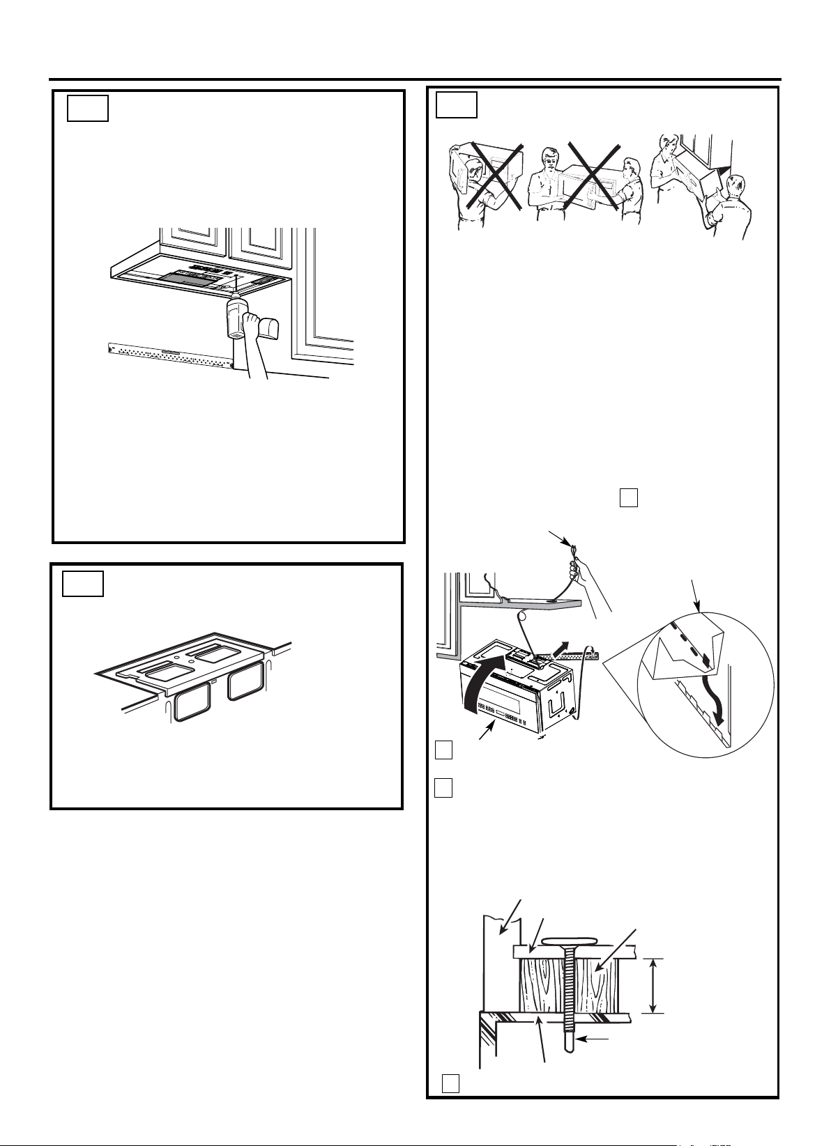
Instrucciones de Instalación
Fije el horno de microondas al gabinete superior.
Frente del Gabinete
Estante de la Parte Inferior del Gabinete
Bloque de Relleno
Equivalente a la
Profundidad de la
Ranura del Gabinete
3
INSTALACIÓN DEL HORNO DE
MICROONDAS
Tornillo Autoalineador
4
2
Gire el frente del horno hacia arriba
para que se encuentre contra la
parte inferior del gabinete.
PARA FACILITAR LA INSTALACIÓN Y GARANTIZAR LA
SEGURIDAD PERSONAL, SE RECOMIENDA QUE LA
INSTALACIÓN DEL PRODUCTO SEA REALIZADA POR
DOS PERSONAS.
IMPORTANTE: No sujete ni use la manija o el protector
térmico durante la instalación. No retire los
espaciadores de cartón entre el protector térmico y la
puerta.
NOTA: Si su gabinete es metálico, use el ojal de nilón
alrededor del orificio del cable de alimentación para evitar
que se corte el cable.
NOTA: Es recomendable usar bloques de relleno si el frente
del gabinete cuelga debajo del estante inferior del gabinete.
IMPORTANTE: En caso de no usar bloques de relleno,
se pueden producir daños en la caja debido a un apriete
excesivo de los tornillos.
NOTA: Al montar el horno de
microondas, pase el cable de
alimentación a través del orificio
en la parte inferior del gabinete
superior. Manténgalo ajustado
por medio de los pasos 1-3.
No pellizque el cable ni levante
el horno por tirar del cable.
Levante el microondas,
inclínelo hacia adelante
y enganche las ranuras
en el borde inferior
trasero en las cuatro
pestañas inferiores de
la placa de montaje.
1
C3.
C4.
USO DE LA PLANTILLA DEL
GABINETE SUPERIOR PARA
PREPARAR EL GABINETE
SUPERIOR
C2.
Necesita perforar agujeros para los tornillos de soporte
superiores y un agujero de largo suficiente para que pase el
cable de alimentación.
● Lea las instrucciones en la PLANTILLA DEL GABINETE
SUPERIOR.
● Péguelo debajo del gabinete superior.
NOTA: Ajuste la plantilla superior según corresponda si el
microondas está separado de la pared debido a que la
profundidad del gabinete (incluidas las puertas del gabinete)
sea más de 13".
● Perfore los orificios de acuerdo con las instrucciones de
la PLANTILLA DEL GABINETE SUPERIOR.
PRECAUCIÓN: Use las gafas de protección al perforar
orificios en la parte inferior del gabinete.
ES-21
Inserte un tornillo autoalineador a través de uno de los
orificios del gabinete superior. Asegure temporalmente el
horno por medio de girar el tornillo al menos dos vueltas
completas después de que las roscas se hayan acoplado.
(Será apretada por completo más tarde.) Asegúrese de
mantener apretado el cable de alimentación. Tenga
cuidado de no pellizcar el cable, especialmente cuando
lo monte al ras de la parte inferior del gabinete.
Parte Superior del Horno de Microondas
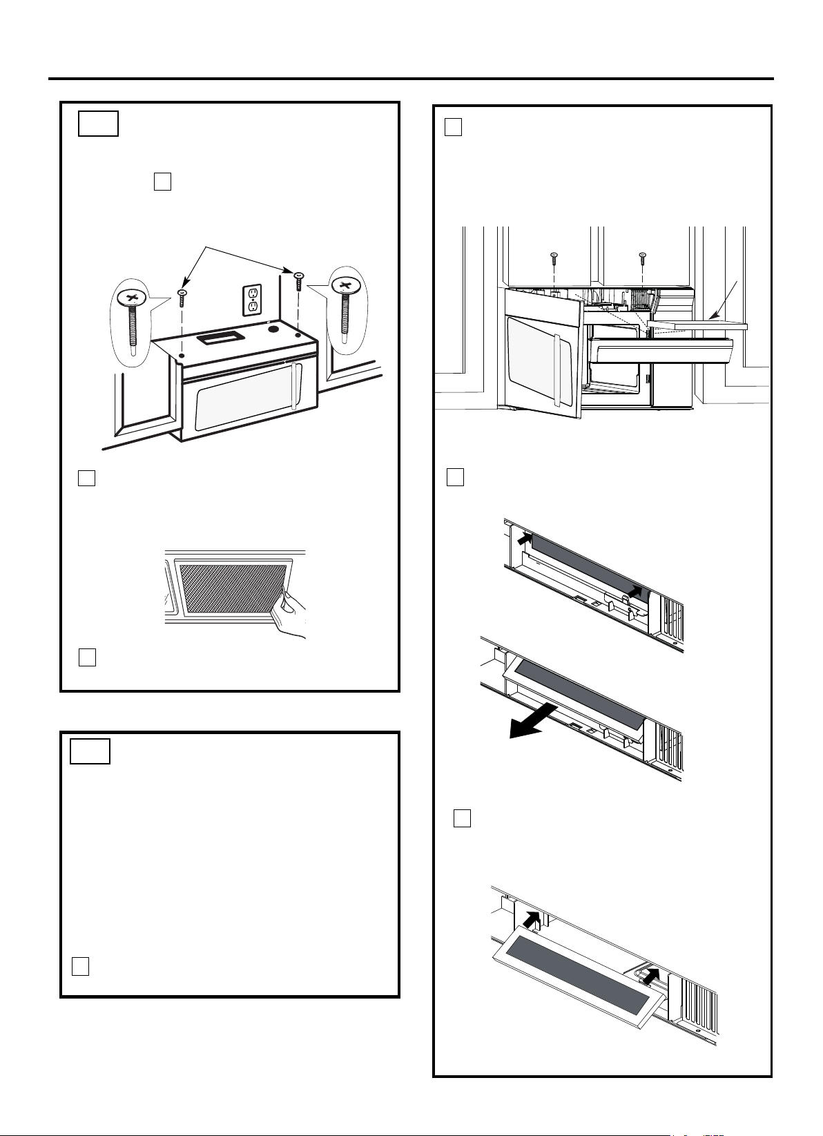
Instrucciones de Instalación
5
INSTALACIÓN DEL HORNO
DE MICROONDAS (continuar)
8
7
Apriete los dos tornillos a la parte superior del
horno de microondas. (Al apretar los tornillos,
sostenga el horno de microondas en su posición
contra la pared y el gabinete superior.)
Instale los filtros de grasa. Consulte el Uso y
Cuidado adjunto con el horno de microondas.
C4.
C5.
INSTALACIÓN O
SUSTITUCIÓN DEL FILTRO DE
CARBÓN (Algunos Modelos)
1 Desenchufe el horno de microondas o desconecte la
alimentación.
NOTA: El filtro de carbón viene instalado al salir de
fábrica para algunos modelos. Consulte el Uso y
Cuidado para saber si el suyo viene instalado al salir de
fábrica y para obtener la información sobre la sustitución.
Algunos modelos contienen una puerta de acceso al
filtro.
Consulte el Uso y Cuidado para ver si el suyo la tiene.
Para modelos sin puerta de acceso al filtro de
recirculación, siga los siguientes pasos para sustituir o
instalar un filtro de carbón.
3
2
4
Retire el filtro de carbón empujando la parte
superior del filtro hacia adentro y luego empújelo
hacia adelante para que salga de la unidad.
Deslice la parte superior del nuevo filtro de carbón
dentro de la parte superior de la cavidad del filtro.
ES-22
Filtro de
Carbón
Inserte el segundo tornillo
autoalineador a través del orificio
restante del gabinete superior.
Gire el tornillo dos vueltas
completas.
Abra la puerta del microondas y use un destornillador
Phillips #2 para sacar los dos tornillos de montaje de
la cubierta de ventilación situados en la parte superior
del horno. Extraiga la cubierta de ventilación tirando
de ella por la parte superior y luego tirando hacia
afuera.
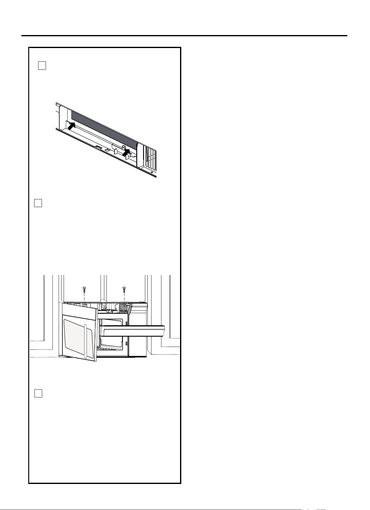
Instrucciones de Instalación
Cierre la puerta del horno. Enchufe el horno
de microondas o vuelva a conectar la
alimentación.
Presione la parte inferior del filtro de
carbón para colocarlo en la posición
correcta.
5
6
7
ES-23
Instale nuevamente la cubierta de
ventilación empujando la parte inferior en su
posición. Empuje la parte superior de
ventilación en su posición y manténgalo en
su lugar. Use un destornillador Phillips #2
para recuperar los dos tornillos de montaje
de la cubierta de ventilación situados en la
parte superior del horno.
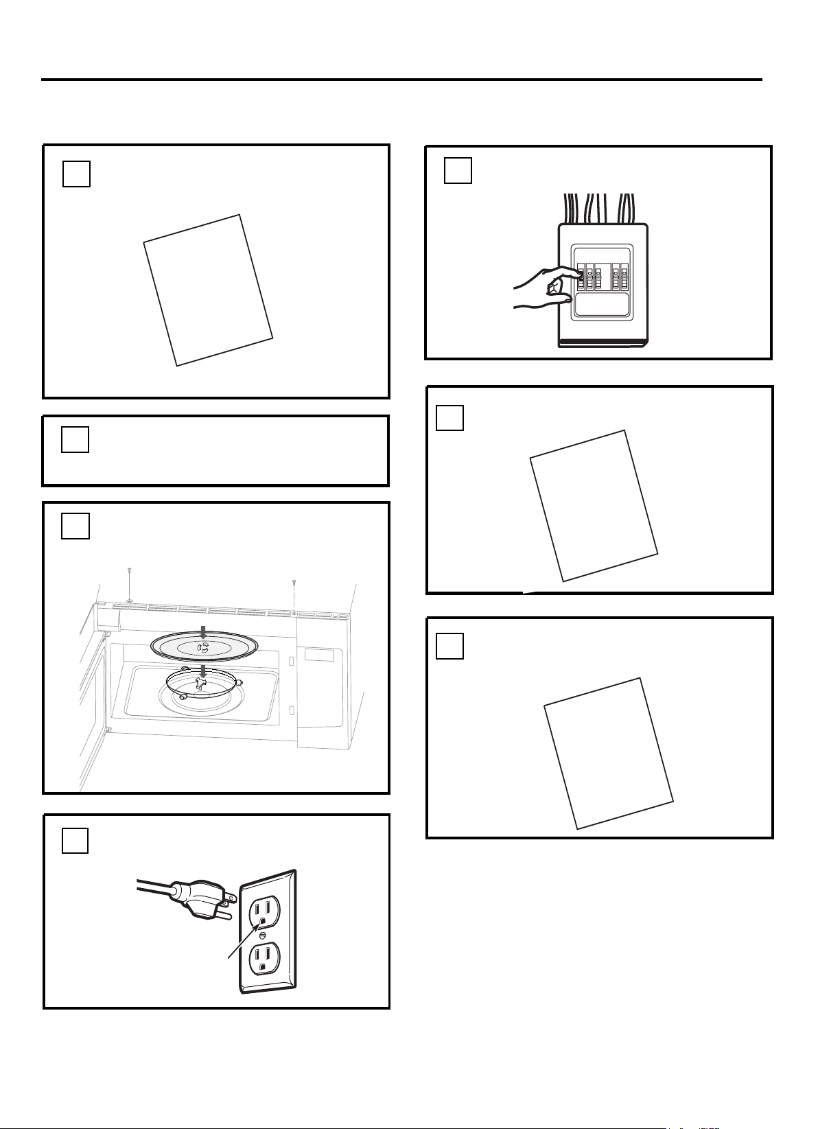
Retire todos los materiales de embalaje del
horno de microondas.
2.
Compruebe que la unidad se ha instalado de
acuerdo con estas instrucciones.
1.
PRECAUCIONES ANTES DEL USO
Asegúrese de que exista
una conexión a tierra
correcta antes del uso
3.
Instale el anillo del plato giratorio, el acoplador
y la bandeja de vidrio en la cavidad.
4.
GUARDE LAS DE
INSTALACIÓN PARA USO DEL INSPECTOR
LOCAL.
7.
6.
MANUAL
DE USO &
CUIDADO
+
D
G
Lea el Manual de USO & CUIDADO.
Recupere el fusible de la casa o vuelva a
encender el disyuntor.
5.
Enchufe el cable de alimentación en un
tomacorriente separado y específico de 15 a
20 amperios.
ES-24
Instrucciones de Instalación
DE
INSTALLAC
IÓN
MANUAL
DE
INSTALLAC
IÓN
MANUAL
Manual
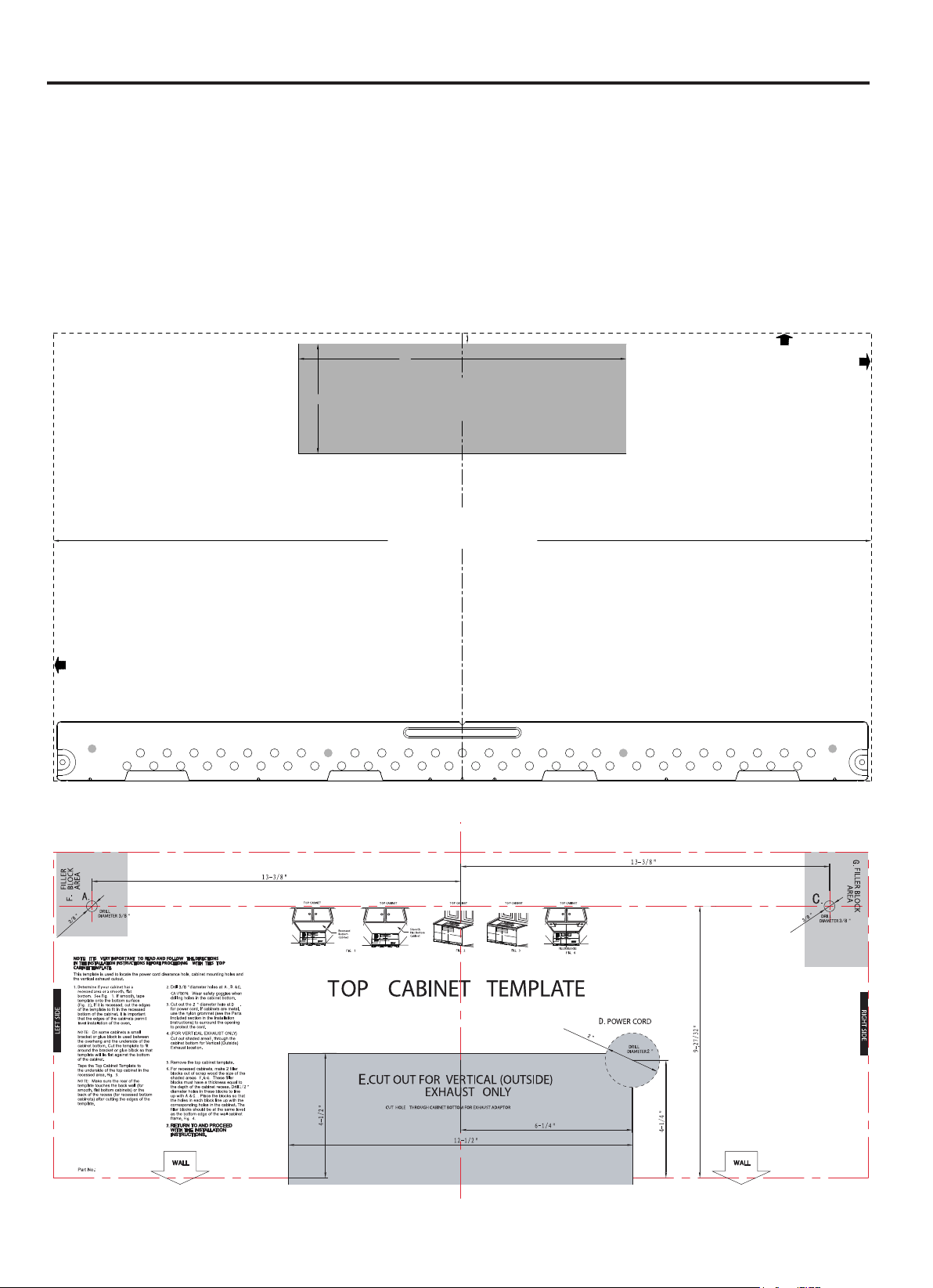
Impreso en China
ES-25
Inspección del funcionamiento
1. Compruebe que la unidad se ha instalado de acuerdo con estas instrucciones.
2. Retire todos los materiales de embalaje del horno de microondas.
3. Recupere el fusible de la casa o vuelva a encender el disyuntor.
4. Enchufe el cable de alimentación en el receptáculo.
5. Lea las instrucciones de operación antes de probar el producto.
6. Encienda el extractor de aire a alta velocidad y confirme que está funcionando con un pañuelo de papel (será adherido al
filtro).
7. Para instalaciones con ventilación exterior, confirme que se ha abierto la aleta de escape exterior.
8. Establezca el horno de microondas durante 1 minuto y confirme que el horno está funcionando normalmente usando una
taza de agua.
9. Guarde las instrucciones de instalación para uso del inspector eléctrico local.
Instrucciones de Instalación
3/8" TO EDGE
NOTE: IT IS VERY IMPORTANT TO
READ AND FOLLOW THE DIRECTIONS
IN THE INSTALLATION INSTRUCTIONS
BEFORE PROCEEDING WITH THIS
REAR WALL TEMPLATE.
This Rear Wall Template serves to position the bottom
mounting plate and to locate the horizontal exhaust
outlet.
1. Use a level to check that the template is positioned
accurately.
2. Locate and mark at least one stud on the left or
right side of the centerline.
It is important to use at least one wood
screw mounted firmly in a stud to support the weight
of the microwave. Mark two additional, evenly spaced
locations for the supplied toggle bolts.
3. Drill holes in the marked locations. Where there is
a stud, drill a 3/16" hole for wood screws. For holes
that do not line up with a stud, drill 5/8" holes for
toggle bolts.
DO NOT INSTALL THE MOUNTING PLATE
AT THIS TIME.
4. Remove the template from the rear wall.
5. Review the Installation Instruction book for your
installation situation.
Locate and mark holes to align with holes in the
mounting plate.
IMPORTANT:
LOCATE AT LEAST ONE STUD ON EITHER SIDE OF
THE CENTERLINE.
MARK THE LOCATION FOR 2 ADDITIONAL, EVENLY
SPACED TOGGLE BOLTS IN THE MOUNTING PLATE
AREA.
Locate and mark holes to align with holes in the
mounting plate.
IMPORTANT:
LOCATE AT LEAST ONE STUD ON EITHER SIDE OF
THE CENTERLINE.
MARK THE LOCATION FOR 2 ADDITIONAL, EVENLY
SPACED TOGGLE BOLTS IN THE MOUNTING PLATE
AREA.
Trim the rear wall template along the dotted line.
Trim the rear wall template along the dotted line.
12"
4"
Darle vuelta a la hoja para consultar la
versión en Español.
PN:261800308463
Part No.:77222
316902476
PN:16170000A75584
3/8" TO EDGE
NOTE: IT IS VERY IMPORTANT TO
READ AND FOLLOW THE DIRECTIONS
IN THE INSTALLATION INSTRUCTIONS
BEFORE PROCEEDING WITH THIS
REAR WALL TEMPLATE.
This Rear Wall Template serves to position the bottom
mounting plate and to locate the horizontal exh aust
outlet.
1. Use a level to check that the t emplate is positioned
accurately.
2. Locate and mark at least one stud on the l eft or
right side of t he c enter line .
It is important to use at l east one wood
screw mounted firmly in a stud to support the weigh t
of the microwave. Mark two additional, evenly s paced
locations for the supplied toggl e bol ts.
3. Drill holes in the marked locat i ons. Where ther e is
a stud, drill a 3/1 6" hole f or wood screws. For holes
that do not line up with a s tud, drill 5/8" holes fo r
toggle bolts.
DO NOT INSTALL THE MOUNTING PLATE
AT THIS TIME.
4. Remove the template from the rear wall.
5. Review the Installation Inst ructio n book for your
installation si t uati on.
Locate and mark holes to alig
n with holes in the
mounting plate.
IM
PORTANT:
LOCATE AT LEAST ONE STUD ON EITHER SIDE OF
THE CENTERLINE.
MARK THE LOCATION FOR 2 ADDITIONAL, EVENLY
SPACED TOGGLE BOLTS IN THE MOUNTING PLA
TE
AREA.
Locate and mark holes to align with holes in the
mounting plate.
IMPORTANT:
LOCATE AT LEAST ONE STUD ON EITHER SIDE OF
THE CENTERLINE.
MARK THE LOCATION FOR 2 ADDITIONAL, EVENLY
SPACED TOGGLE BOLTS IN THE MOUNTING PLATE
AREA.
Trim the rear wall template along the dotted line.
Trim the rear wall template along the d
otted line.
12"
4"
Darle vuelta a la hoja para consultar la
versión en Español.
3/8" TO EDGE
NOTE: IT IS VERY IMPORTANT TO
READ AND FOLLOW THE DIRECTIONS
IN THE INSTALLATION INSTRUCTIONS
BEFORE PROCEEDING WITH THIS
REAR WALL TEMPLATE.
This Rear Wall Template serves to position the bot tom
mounting plate and to locate the horizontal exhaust
outlet.
1. Use a level to check that the templ ate i s positioned
accurately.
2. Locate and mark at least one stud on the l eft or
right side of t he cent erl i ne.
It is important to use at l east one wood
screw mounted firmly in a stud to support the weight
of the microwave. Mark two additional, evenly spaced
locations for the supplied toggle bolt s.
3. Drill holes in the marked l ocati ons. Where there i s
a stud, drill a 3/16" hol e for wood screws. For holes
that do not line up wit h a stu d, drill 5/8" holes for
toggle bolts.
DO NOT INSTALL THE MOUNTING PLATE
AT THIS TIME.
4. Remove the template from the rear wall.
5. Review the Installation Instr ucti on book f or your
installation si t uati on.
Locate and mark holes to align with holes in th e
mounting plate.
IMPORTANT:
LOCATE AT LEAST ONE STUD ON EITHER SIDE OF
THE CENTERLINE.
MARK THE LOCATION FOR 2 ADDITIONAL, EVENLY
SPACED TOGGLE BOLTS IN THE MOUNTING PLATE
AREA.
Locate and mark holes to align with holes in th e
mounting plate.
IMPORTANT:
LOCATE AT LEAST ONE STUD ON EITHER SIDE OF
THE CENTERLINE.
MARK THE LOCATION FOR 2 ADDITIONAL, EVENLY
SPACED TOGGLE BOLTS IN THE MOUNTING PLATE
AREA.
Trim the rear wall template along the dotted line.
Trim the rear wall template along the dotted line.
12"
4"
Darle vuelta a la hoja para consultar la
versión en Español.
A06823428


LISTA DE CONTROLO DE INSTALLACIÓN
1. Asegúrese de que la unidad ha sido instalada e acuerdo con todas las instrucciones de instalación,
el modelo superior. y el modelo de pared.
2. Remueva todo el
3. Conecte el cable de energía.
4. Lea el manual de
5. Conserve las
ACCESORIOS
Revise con su vendedor o pida
Llame al 1-800-BE
1. (RK233). l filtro de carbón se utiliza cuando el sistema de escape del extractor
es recirculado.
2. Filtro de grasa (RK235).
material de embalaje del horno
operación.
instrucciones de instalación para el uso del inspector eléctrico local.
directamente al centro de accesorios y suministros SHARP.
E
Filtro de
carbón
d
SHARP (237-4277)

PN:16170000A96562