Loading ...
Loading ...
Loading ...
8 9
Crossover
The topology of the crossover of the LS50 Meta is
shown in gure 24. The smoother response of the
new tweeter has resulted in fewer components in the
HF lter and the remaining series capacitor (C1) is of
higher quality.
The LF lter is similar to that in the original LS50, but
includes an extra low-Q parallel resonance branch (C3-
R3-L4) to compensate for the higher sensitivity in the
driver’s upper midrange due to its lower inductance.
The inductor L4 is the only one in the crossover to
have a core. It is vital that only the resistor R3 controls
the Q of the branch. To that end, the resistance of
L4 (which is subject to change as it heats up when
passing current) is kept as low as possible. As the core
is a possible source of harmonic distortion if it nears
saturation, measurements were taken to relate the
current passing through L4 with that passing through
L2. Figure 25 shows that it will be seen that the current
passing through L4 is much lower and the chances of
its core saturating are virtually nil, a fact borne out by
the THD measurements of gure 23.
To minimise any coupling between inductors, the
three in the LF lter are arranged orthogonally and
the HF lter is on a separate board, placed well away
from the LF lter.
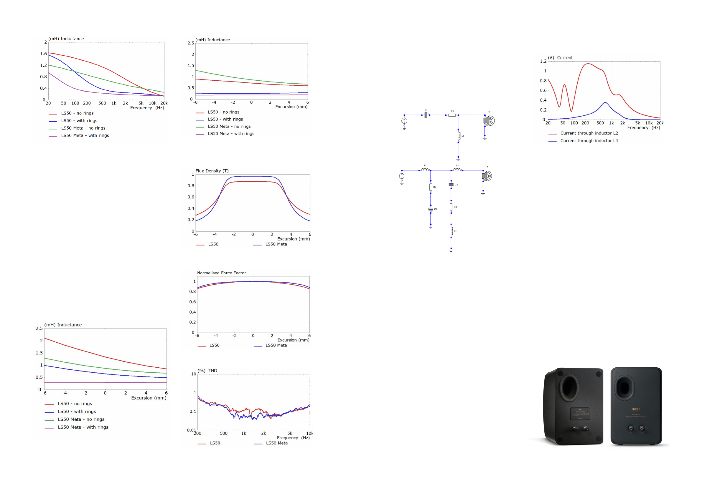
Industrial Design
Little has changed from the original LS50, but there
are a few detailed changes to the back of the cabinet
to improve performance and enhance looks (gures 1
& 26):
• The port opening is now ush with the rear
surface, which further reduces turbulence.
• The 4 cavities in the corners for the bafe
retention bolts have been eliminated.
• The rear surface is now slightly domed.
• A step transition between the rear panel and
the sides of the cabinet has been introduced.
• There is now a soft notch around each
binding post.
The change in magnet design has had two further
advantages. The undercut centre pole gives higher
ux density in the gap itself and lower magnetic
fringing (gure 21). This results in higher sensitivity of
the driver and more linear drive at higher excursions
(gure 22).
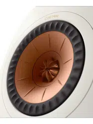
Looking at gures 18-22 together, we see that the
new design gives less modulation of the magnet ux
density in the gap, more linear drive, lower voice coil
inductance and virtually no change in inductance with
voice coil position. The upshot of all this analysis and
redesign is a signicant reduction in total harmonic
distortion (THD) in the frequency range where the ear
is at its most sensitive (gure 23).
Figure 25
Current consumption of inductors L2 and L4
for an input of 2.83V.
Figure 19
Bass/midrange blocked voice coil inductance against frequency.
Figure 20b
Bass/midrange voice coil inductance against displacement
at 200Hz (gure 20a) and 2kHz (gure 20b).
Figure 21
Comparison of ux density in the gap.
Figure 22
Comparison of bass/midrange force factor
Figure 23
THD, measured as a percentage of the fundamental level
90dB SPL at 1m for LS50 (red) and LS50 Meta (blue).
Figure 24
LS50 Meta crossover topology
Figure 20a
Figure 26
Rear views of LS50 (left) and LS50 Meta (right)
Loading ...
Loading ...
Loading ...