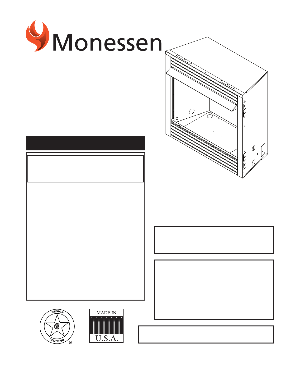
710530
GCUF cover
Do Not Build a Wood Fire.
Installation and
Operating Instructions
71D0530 1/11 Rev. 7

71D0530
GCUF Vent-Free Fireboxes
Before You Start ......................................................5
What You Will Need for Installation .........................5
Optional AK-4 Outside Air Kit ................................13
Model 403 Duct Connector ...................................14
3
71D0530
GCUF Vent-Free Fireboxes
13. Correct installation of the ceramic ber logs, proper
location of the heater, and annual cleaning are neces-
sary to avoid potential problems with sooting. Sooting,
resulting from improper installation or operation, can
settle on surfaces outside the replace. See log place-
ment instructions for proper installation.
14. Avoid any drafts that alter burner ame patterns. Do not
allow fans to blow directly into replace. Do not place
a blower inside burn area of rebox. Ceiling fans may
create drafts that alter burner ame patterns. Sooting
and improper burning will occur.
15. Candles, incense, oil lamps, etc. produce
combustion byproducts including soot. Vent-free appli-
ances will not lter or clean soot produced by these
types of products. In addition, the smoke and/or aro-
matics (scents) may be reburnt in the vent-free appli-
ance which can produce odors. It is recommended to
minimize the use of candles, incense, etc. while the
vent-free appliance is in operation.
16. An unvented gas-red heater uses air (oxygen) from
the room in which it is installed. Provisions for adequate
combustion and ventilation air must be provided. See
installation guidelines.
17. Keep room area clear and free from combustible
materials, gasoline and other ammable vapors and
liquids.
18. Unvented gas heaters are a supplemental zone heater.
They are not intended to be a primary heating appli-
ance.
19. Unvented gas heaters emit moisture into the living
area. In most homes of average construction, this
does not pose a problem. In houses of extremely
tight construction, additional mechanical ventilation is
recommended.
0. During manufacturing, fabricating and shipping, various
components of this appliance are treated with certain
oils, lms or bonding agents. These chemicals are not
harmful but may produce annoying smoke and smells
as they are burned off during the initial operation of the
appliance; possibly causing headaches, or eye or lung
irritation. This is a normal and temporary occurrence.
8. Early signs of
carbon monoxide poisoning are similar to the u with
headaches, dizziness and/or nausea. If you have these
signs, obtain fresh air immediately. Have the heater
serviced as it may not be operating properly.
9. The installation must conform with local codes or, in
the absence of local codes, with the National Fuel Gas
Code, ANSI Z3.l/NFPA54.
10. This unit complies with ANSI Z1.91 ventless rebox
enclosures for gas-red unvented decorative room
heaters.
11. Do not install the unvented heater in a bathroom.
1. Do not install the unvented heater in a bedroom unless
the maximum input rating is equal to or less than
10,000 Btu/hr.
Continued on page 4
Please leave these instructions with the appliance.
Please retain these instructions for future reference
.
1. Due to high temperatures, the rebox should be
located out of trafc and away from furniture and
draperies.
. Children and adults should be alerted to the hazard
of high surface temperature and should stay away
to avoid burns or clothing ignition.
3. Young children should be carefully supervised when
they are in the same room with the rebox.
4. Do not place clothing or other ammable material
near the replace when the rebox is in use.
5. Any safety screen or guard removed for servicing,
must be replaced prior to operating a heater within
the rebox.
6. Installation and repair should be done by a qualied
service person.
7. To prevent malfunction and/or sooting, an unvented
gas heater/rebox should be cleaned at least annu-
ally by a professional service person. More frequent
cleaning may be required due to excessive lint from
carpeting, etc. It is imperative that control compart-
ments, burners and circulating air passageways be
kept clean.
71D0530
4
GCUF Vent-Free Fireboxes
Continued from page 3
The initial break-in operation should last two to three
hours with the burner at the highest setting. Provide
maximum ventilation by opening windows or doors to
allow odors to dissipate. Any odors remaining after this
initial break-in period will be slight and will disappear
with continued use.
1. Input ratings are shown in BTU per hour and are for
elevations up to ,000 feet. For elevations above ,000
feet, input ratings should be reduced 4 percent for each
1,000 feet above sea level. Refer to the National Fuel
Gas Code.
. The appliance and its appliance main gas valve must
be disconnected from the gas supply piping system
during any pressure testing of that system at test pres-
sures in excess of 1/ psig (3.5 kPa).
3. The appliance must be isolated from the gas supply
piping system by closing its equipment shutoff valve
during any pressure testing of the gas supply piping
system at test pressures equal to or less than 1/ psig
(3.5 kPa).
4. Do not use this room heater if any part has been under
water. Immediately call a qualied service technician
to inspect the room heater and to replace any part of
the control system and any gas control which has been
under water.
5. Never burn solid fuels in a replace where a unvented
room heater is installed.
6. Always have a replace screen in place when the
appliance is in operation, and unless other provisions
for combustion air are provided, the screen shall have
an opening(s) for induction of combustion air.
7. Do not ll spaces around the rebox with insulation or
other materials. These spaces must be maintained to
prevent the rebox from coming in contact with com-
bustible materials.
Nous recommandons que nos
appareils de chauffage au gaz
soient installés et entretenus par
des professionnels qui ont été
accrédités aux È.U. par le National
Fireplace Institute ® (NFI) comme
étant des spécialistes du NFI en
matièred’appareils de chauffage
au gaz.

5
71D0530
GCUF Vent-Free Fireboxes
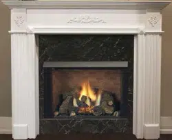
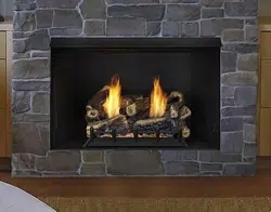
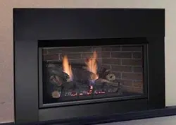
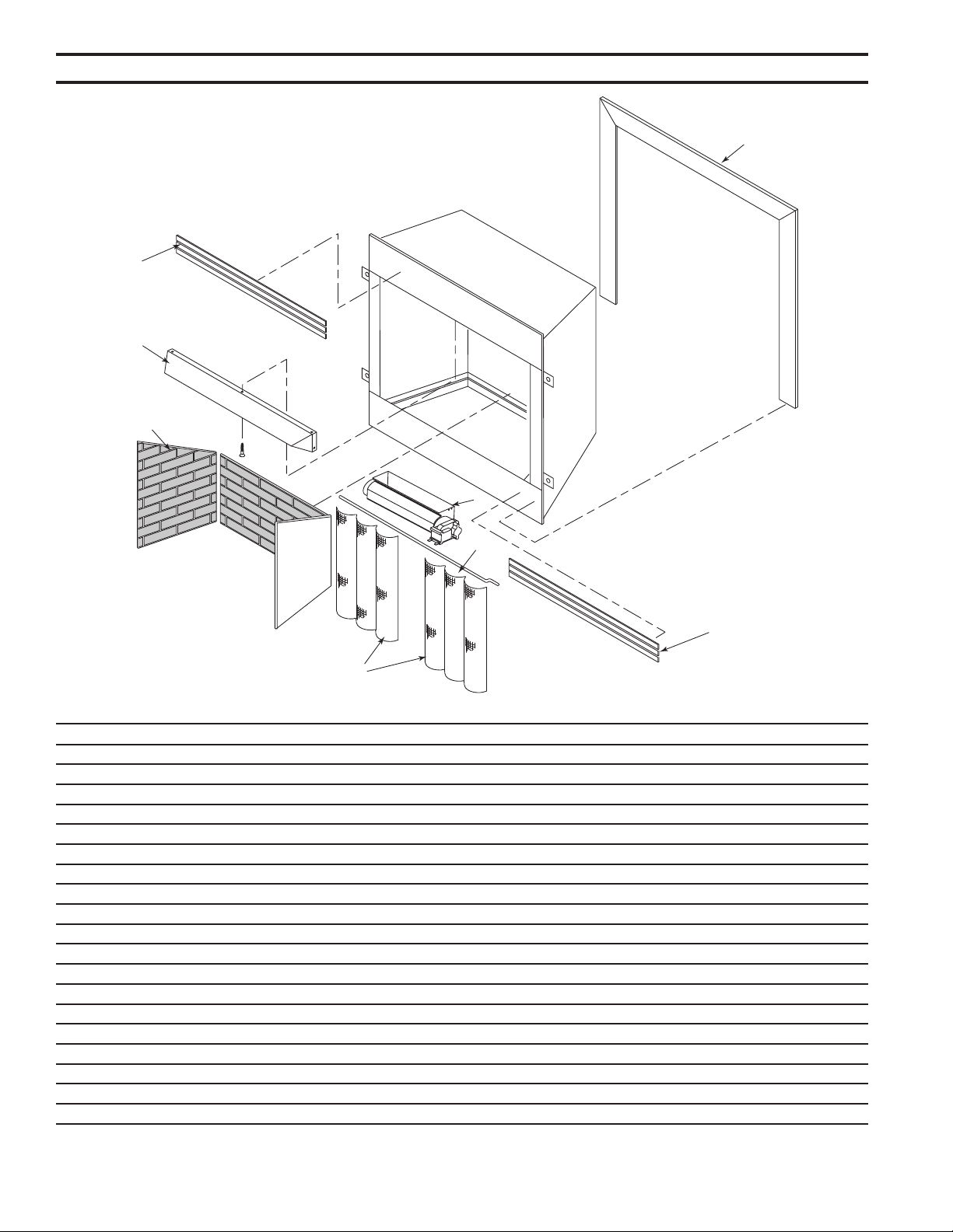
The new GCUF and GRUF Series are vent-free reboxes.
They feature a self contained heat-circulating system.
These units also feature a -in1, exible-face system, sold
as an accessory, that converts the circulating system into
a radiant system in seconds.
This installation manual will enable you to obtain a safe,
efcient and dependable installation of your vent-free
replace system.
Do not alter or modify the rebox or its components under
any circumstances. Any modication or alteration of the
rebox system, including but not limited to the rebox and
accessories, may void the warranty, listings and approvals
of this system and could result in an unsafe and potentially
dangerous installation.
Carefully inspect the contents for shipping damage. If any
parts are missing or damaged, immediately inform the
dealer from whom you purchased the appliance. Do not
attempt to install any part of the appliance unless you have
all the parts in good condition.
Check your packing list to verify that all listed parts have
been received. You should have the following:
1. Vent-Free Gas Firebox
. Canopy
3. Installation and Operating Instructions
4. Five (5) sheet metal screws for canopy
• Phillips screwdriver • Square
• Framing materials • Hammer
• Saw and / or saber saw • Tee joint
• Level • Pipe wrench
• Measuring tape • Pliers
• Electric drill and bits
• Fireplace surround materials (noncombustible)
• Caulking material (noncombustible)
• Wall nishing materials
•
Piping complying with local codes
• Pipe sealant approved for use with propane/L.P.G.
(resistant to sulfur compounds)
Refer to the installation instructions provided with the log
sets for items required for log set installation.
In planning the installation for the appliance it is necessary
to determine where the unit is to be installed and whether
optional accessories are desired. Gas supply piping should
also be planned. The following steps represent the normal
sequence of installation. Each installation is unique, how-
ever, and might require a different sequence.
1. Position rebox prior to framing or into prepared fram-
ing.
. Field wire main power supply to models with fan kit.
(Electrical connections should only be performed by an
experienced, licensed /certied tradesman).
3. Plumb gas line. (Gas connections should only be per-
formed by an experienced, licensed/certied trades-
man).
4. Install vent-free gas log heater per the instructions
provided with the vent-free gas log heater.
5. Complete nish wall material, surround and optional
hearth extension to your individual taste.
71D0530
6
GCUF Vent-Free Fireboxes
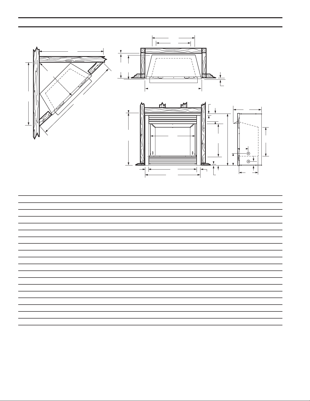
256O”
B
256O”
A
Rough
Opening
Height
D
F
C
Rough
Opening
Depth
M - Rough Opening Width
1/2” - 5/8”
O
Q
P
P
R
710530
GCUF dims
I
156M”
6”
16QE”
5(6QE”
N
216M”
E
H
J
L
G
K
A 37" 41" 47"
B 3" 36" 4"
C 16" 18" 18"
D 9" 3" 38"
E 18B\," 0B\," 0B\,"
F 3C\," 7C\," 33C\,"
G 13Z\v" 15C\v" 15C\v"
H 18" 17B\," 17B\,"
I 9M\," 34" 40"
J 7Z\," 9C\v" 9C\v"
K 8" 8Z\v" 8Z\v"
L C\v" Z\v" Z\v"
M 37Z\v" 41Z\v" 47Z\v"
N 35" 35" 35"
O 15Z\x" 17Z\x" 17Z\x"
P 43C\v" 48C\v" 53"
Q 61C\v" 68M\," 74M\,"
R 30M\," 34Z\x" 37Z\x"
Figure 1 -
Firebox and Framing Dimensions
7
71D0530
GCUF Vent-Free Fireboxes
A
B
C
D
E
FP2901
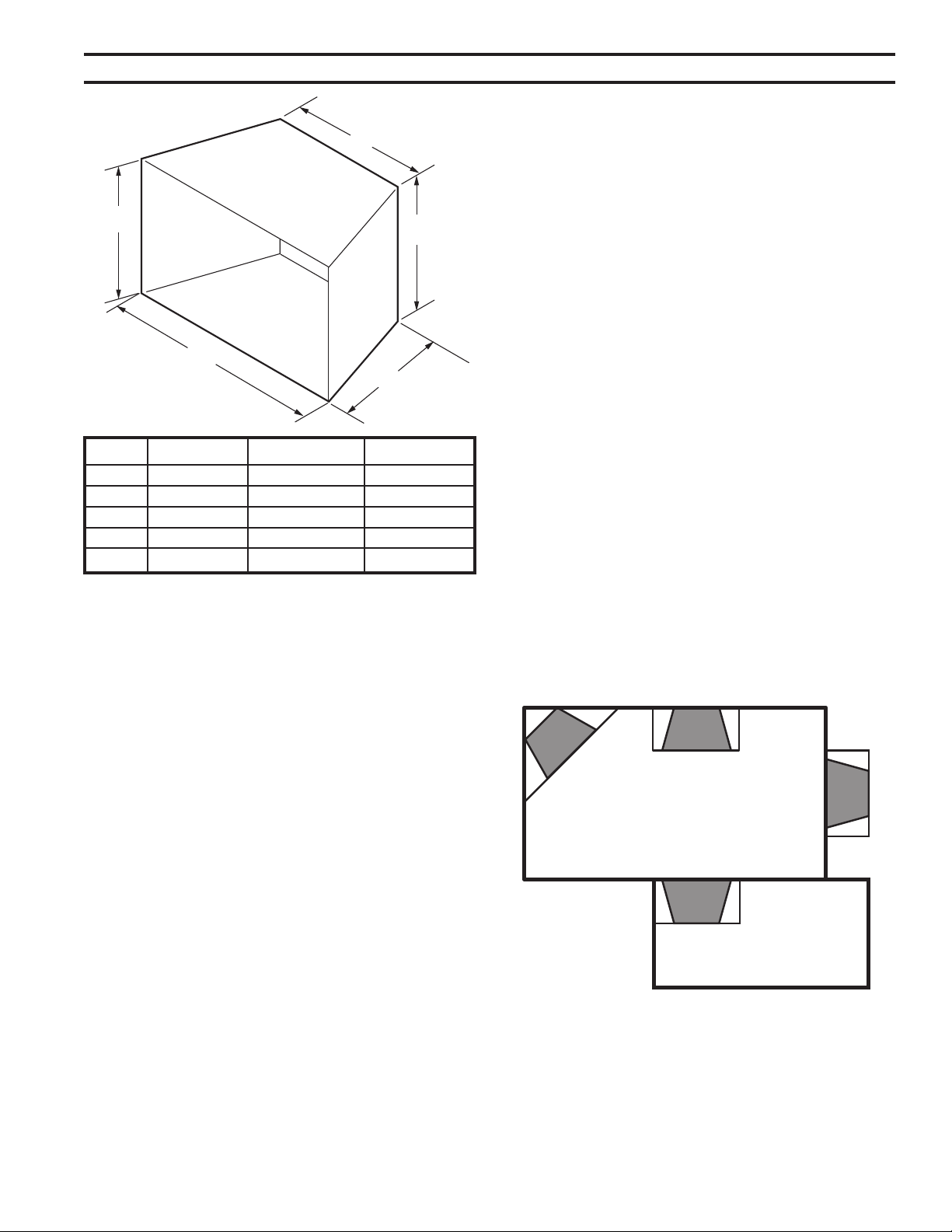
hearth dims
A 9M\," 34" 40"
B 13Z\v" 15C\v" 15C\v"
C 3C\," 7C\," 33C\,"
D 1M\," 1M\," 1M\,"
E 18" 17B\," 17B\,"
Figure 2 -
Minimum Hearth Dimensions
Carefully select the best location for installation of your
vent-free rebox. The following factors should be taken
into consideration:
• Clearance to side wall, ceiling, woodwork and windows.
See “Clearances/Height Requirements on page 8.
Minimum clearances to combustibles
• Location must not be affected by drafts caused by
kitchen exhaust fans, ceiling fans, return air registers
for forced air furnaces / air conditioners, windows or
doors.
• Installation must provide adequate ventilation and com-
bustion air.
•
• Location should be out of high trafc or windy or drafty
areas.
•
• Never obstruct the front opening of the vent-free rebox
or restrict the ow of combustion and ventilation air.
• Minimize modications to existing construction. Refer
to Figure 3 below for location suggestions.
• Do not install in the vicinity where gasoline or other
ammable liquids may be stored. The vent-free rebox
must be kept clear and free from these combustible
materials.
FP2440
fireplace locations
Figure 3 -
Location of Firebox
FP440
71D0530
8
GCUF Vent-Free Fireboxes
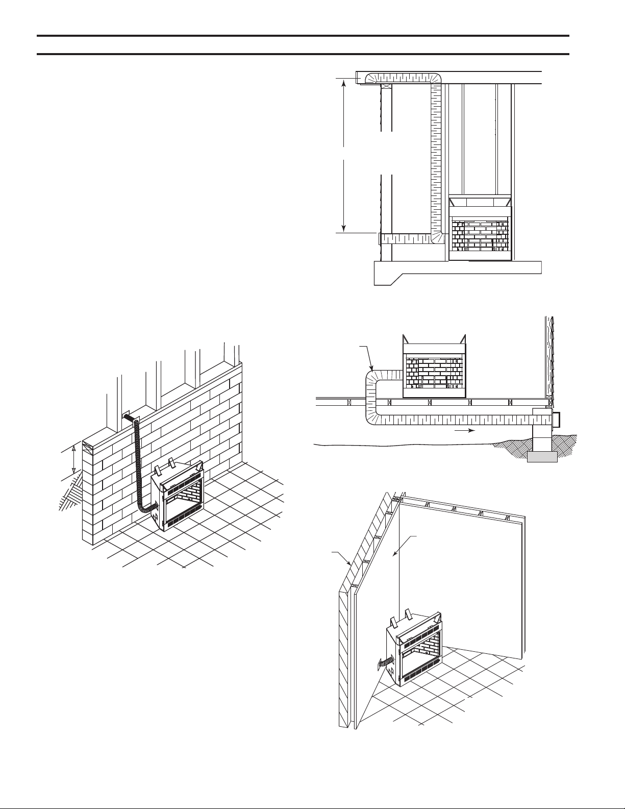
Ensure that minimum clearances shown in Figures 4
through 8 are maintained. Left and right clearances are
determined when facing the front of the rebox.
Follow these instructions carefully to ensure safe instal-
lation. Failure to follow these requirements may create a
re hazard.
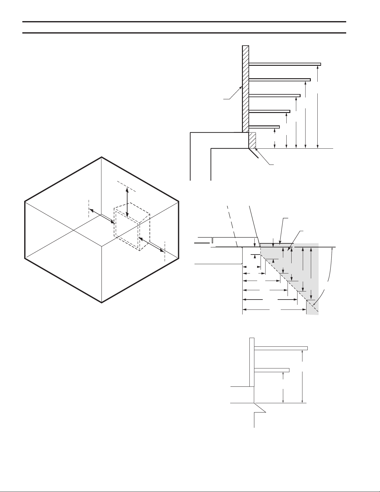
1. The clearance from the inside
of the appliance to any combustible wall should not be
less than 9". Figure 4
. The ceiling must be at least 4”
from the top of the rebox opening. Figure 4
3. The appliance may be placed
against a combustible back wall.
9"
Minimum
42"
Minimum
9"
Minimum
FP2687
minimum clearances
FP687
Figure 4 -
Clearance and Height Requirements
4. The canopy supplied with the unit
must be installed. If a combustible mantel is installed,
it must meet the clearance requirements as shown in
Figure 5. However, if lower mantel height is desired,
refer to Page 14, Figure 6.
12”
10”
8”
6”
256O”
12”
16”
19”
21”
23”
FP2690
Mantel clearances
Combustible
Material Can
Contact Top
of Fireplace
FP690
Noncombustible Material
Only if Needed to Cover
Radiant Top Face
Figure 5 -
Mantel Clearances
12”
8”
8”
14”
FP2691
mantel clear wide canopy
FP691
Figure 6 -
Mantel Heights for Wide Prole Canopy
45°
1”
256O”
3”
5”
6”
56O”
56O”
56O”
FP2692
mantel leg clearance
6”
756O”
756O”
9”
Finish Wall
Combustible
Material Area
FP69
Figure 5a -
Mantel Leg Clearance
9
71D0530
GCUF Vent-Free Fireboxes
FP2688
min floor combustible
5" Minimum
Combustible
Material
FP688
Figure 7 -
Minimum Clearance Above
Combustible Flooring
14” Minimum
FP2689
min floor clear noncomb
Can be Less
Than 5"
Noncombustible
Material
FP689
Figure 8 -
Minimum Clearance above Combustible Flooring with
Noncombustible Material Installed at Base of Fireplace
Firebox framing can be built before or after the appliance
is set in place. Construct rebox framing following Figure
1 for your specic installation requirements. See Figure 1
on Page 6 for rebox dimensions. The framing headers
may rest on the top of the rebox.
The rebox may be installed directly on a combustible oor
or raised on a platform of an appropriate height. When
the rebox is installed directly on carpeting, tile, or other
combustible material, other than wood ooring, the rebox
shall be installed on a metal or wood panel extending the
full width and depth of the enclosure.
The classication "noncombustible material" includes, but
is not limited to: stone, brick, and mortar. Noncombustibles
are safe to overlay the black-painted metal face, including
radiant plates, and do not pose a re hazard. Any noncom-
bustible nish material must not extend past or interfere
with the replace opening.
The classication "combustible material" incudes, but is
not limited to: plywood, drywall, and particle board. Com-
bustible materials may contact the sides, bottom, or back
of the rebox. Do not overlay the black painted face with
combustible materials.
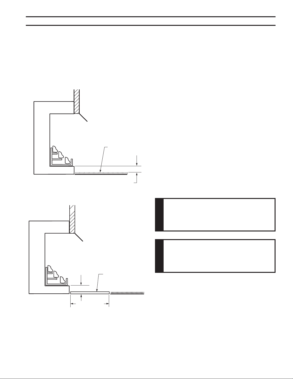
This inner chamber rebox oor must
be installed at least 5" above any combustible ooring
material, such as carpeting or asphalt tile, which is
closer than 14" to the base of the rebox. Figure 7
OR
The inner chamber rebox oor may be installed nearer to
the oor if a minimum of 14" of noncombustible ma terial
such as slate or marble is installed between the base of
the rebox and the combustible ooring. Figure 8
71D0530
10
GCUF Vent-Free Fireboxes
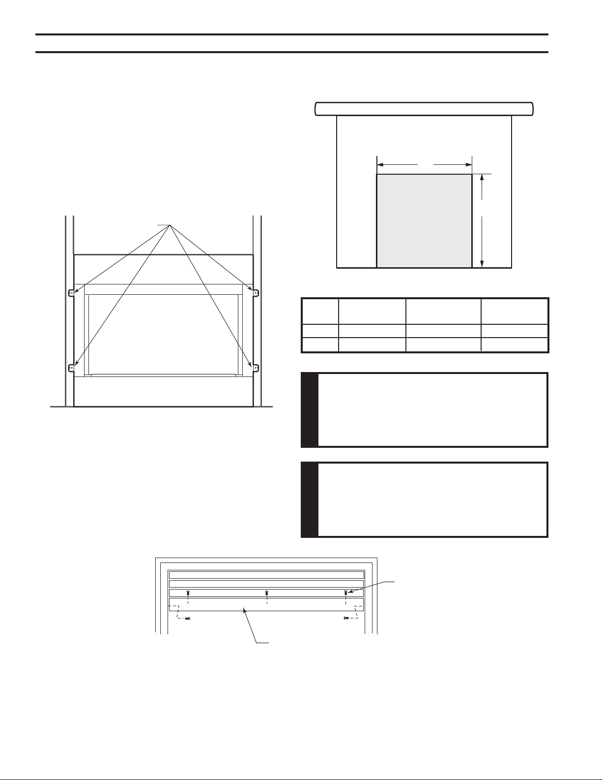
When nishing a custom cabinet, mantel, or other built-in
enclosure, the opening size to accommodate the replace
with trim installed is as follows:
Figure 10 -
Custom Cabinet
A
B
FP2694
custom cabinet
A 37M\," 41M\," 47M\,"
B 35M\," 35M\," 35M\,"
A canopy is furnished with each rebox and MUST be
installed for safe operation. Figure 11
1. Align the canopy with the holes in the top frame.
. Secure the screws as shown.
3. Tighten side screws. Make sure the canopy is level and
secure.
Figure 11 -
Installing Canopy
FP2451
install canopy
Screws
Canopy
FP451
1. Bend out the nailing anges located on each side of the
rebox.
. Slide the rebox into prepared framing or position rebox
in its nal position and frame later.
3. Level the rebox by checking the top edge of the rebox.
Shim if necessary.
4. Anchor rebox to the side framing members using 8d
nails or other suitable fasteners. Figure 9.
5. The canopy must be installed for safe operation of the
heater.
FP2902
nailing flanges
Nail Sides Through
Nailing Flanges
FP90
Figure 9 -
Location of Nailing Flanges
11
71D0530
GCUF Vent-Free Fireboxes
Consult all local codes. All gas piping must be installed to
comply with local codes, or in the absence of local codes,
with the latest edition of the National Fuel Gas Code ANSI
Z3.1/NFPA54.
Remove the baseplate for ease of gas line installation.
Remove screws along the front edge of the baseplate
and bottom center piece of the rebox and set aside. Lift
baseplate and pull toward you. Replace baseplate prior to
connecting gas line to heater. Consult heater installation
and operating instructions for correct installation of the
heater into the rebox.
The 1/" gas line may enter either from the left side or right
side of the rebox. Gas access holes are provided on both
sides of the rebox.
A listed manual shutoff valve must be installed upstream
of the appliance. A union tee and plugged 1/8" NPT pres-
sure tapping point should be installed upstream of hte
appliance.
A sediment trap may be upstream of the heater to prevent
moisture and contaminants from passing through trap to
the heater controls and burners. Failure to do so could
prevent the heater from operating reliably. Consult appli-
cable codes.
An external regulator must be used on all propane/L.P.G.
heaters, in addition to the regulator tted to the heater, to
reduce the supply tank pressure to 13" w.c. (maximum).
Any copper tubing used to supply propane / L.P.G. from
the tank must be internally tinned.
After completing connection, test all gas joints from the
gas meter to the gas heater regulator for leaks. Using
soap and water solution or a gas sniffer. DO NOT USE
AN OPEN FLAME.
71D0530
1
GCUF Vent-Free Fireboxes
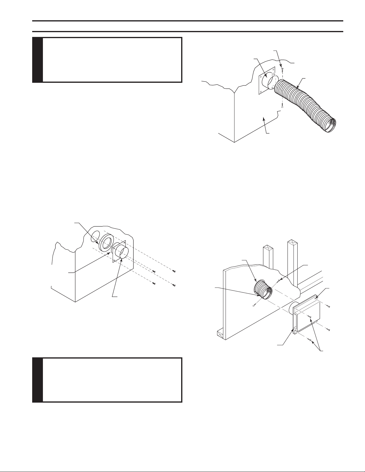
1. Locate combustion air assembly at an exterior location
which is not likely to be accidentally blocked in any man-
ner. Locate assembly a min. of 1" above the snow line
to prevent blockage by snow accumulation.
. Never mount the combustion air inlet assembly in a
garage or storage area where combustible fumes such
as gasoline might be drawn into the replace.
3. Combustion air can be drawn from the crawl space un-
der a house when an adequate supply of air is provided
by open ventilation.
4.
5. Locate air supply inlet at least 3' away from any ap-
pliance vent terminal.
6. Avoid extremely long runs and numerous turns in the
duct leading from the replace to the combustion air
assembly. These conditions increase the resistance to
the free ow of air through the duct. Refer to Figures
12 through 15 for methods of installing the outside air
for combustion assemblies.
FP2459
OA basement install
Above
Snow
Level
Ground
Level
FP459
Figure 12 -
Basement Installation
8' Max.
FP2460
OA slab install
Inlet Grille
in Soft
(Overhang)
FP460
Figure 13 -
Concrete Slab Installation
(Optional Outside Air Runs)
FP2461
above basement
Duct
Extended
to Miss
Joist
FP461
Figure 14 -
Installation Above Basement or
Crawl Space
To Outside Wall
FP2462
OA corner install
Outside
Wall
Inside Wall
FP46
Figure 15 -
45° Corner Installation
on Slab Floor
13
71D0530
GCUF Vent-Free Fireboxes
The use of outside air for combustion is optional unless
required by building codes. It is only necessary to supply
outside combustion air to one side of the replace. Use the
model AK4 combustion air kit.
1. Remove the cover plate from the 4" outlet opening loca-
tion on the left or right outside of the replace.
. Place the insulation ring between the AK-4 starting collar
and replace wall.
3. Place the starting collar (4") into the hole on the side
of replace. Fasten it in place with the four sheet metal
screws provided. Figures 16 and 17
FP1900
OA start collar
8/08
Figure 16 -
Attach Outside Air Starting Collar and Insulation
Ring to Left Side of Fireplace
Insulation
Ring
AK-4 Starting
Collar
Sheet Meal
Screws
Left Side of
Fireplace
Shorter End
of Air Starting
Collar
4. Attach outside duct to starting collar with duct clamp or
screws. Figure 17
5. Cut a 6-inch diameter opening for model AK-4 in the
outside wall covering where the outside vent is to be
located. Figure 18
6. Select and cut a piece of duct long enough to attach to
the replace and stick out at least 3" beyond the face of
the wall to which the AK-4 inlet air vent will be attached.
Cut duct with a standard pocket knife. Figure 17
FP2700
OA duct
Screws
Air Starting
Collar
Duct
Left Side of
Fireplace
FP700
Figure 17 -
Attach Outside Duct to Starting Collar
FP1904
AK4 install
8/08
6"
Diameter
Hole
Duct
Extending
3" Min.
Screws
Nail
Hole
Screws
AK-4 Inlet
Air Vent
Figure 18 -
Combustion Air Assembly for Model
AK-4
FP1904
71D0530
14
GCUF Vent-Free Fireboxes
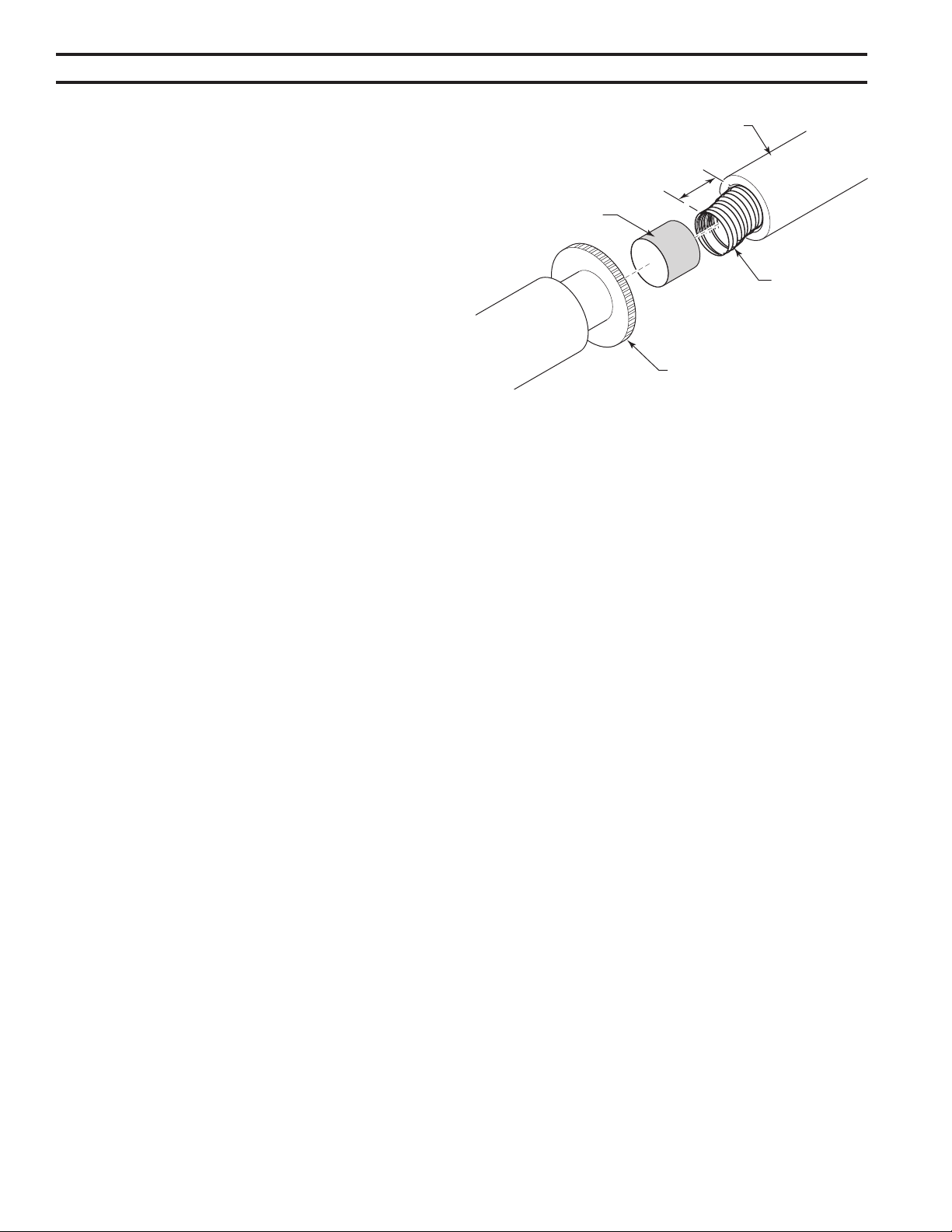
7. If the duct is the insulated type, push the insulation back
from one end of the duct approximately ". Figure 19
8. Slip the exposed end of the duct over the starting collar
on the replace.
9. Using the sheet metal screws provided, secure the duct
end to the collar attached to the replace.
10.Nail or screw the combustion air assembly to the surface
of the wall.
1. Push insulation back approximately " from the end of
each duct.
. Slip each duct over duct connector until an equal length
of connector extends into each duct.
3. Place duct clamp over the end of each duct. Tighten
duct clamp down snuggly.
4. Push insulation back into place and over duct clamp.
FP1907
Duct connector
8/08
Approximately
2”
Figure 19 -
Install Duct Connector 403
Insulation
Duct
Connector
Duct Clamp
Duct
FP1907
15
71D0530
GCUF Vent-Free Fireboxes
(BLOTMC)
If you are installing the forced air kit on GCUF or GRUF models, see the installation instruc-
tions provided with the kit for electrical wiring requirements, or the blower installation section.
The rebox must be connected to main power supply at time of rebox installation. The blower
must be installed prior to the installation of the vent-free heater. The electrical connections
must be made before the rebox is framed and enclosed in the nished walls.
Optional brass or pewter louver kits may be installed in place of the factory installed black
louvers. Refer to installation instructions provided with the brass or pewter louvers.
Optional trim kits can be used with unit when installed as a free standing replace with
wood surround.
Optional rebrick kits can be installed. See installation instructions provided with kit.
The optional wide canopy can be installed. See installation instructions provided with kit.
71D0530
16
GCUF Vent-Free Fireboxes
5
1
2
4
7
6
4
3
710530
GCUF parts
1. Canopy 1 71D003 71D0500 71D1000
. Screen Panel 61D0001 61D0001 61D0003
3. Screen Rod 6D0138 6D013 6D0133
4. Black Louver 6 6D0695 6D0697 6D0699
1. Standard Brass Canopy 1 BRCU3 BRCU36 BRCU4
1. Wide Brass Canopy 1 BRC3 BRC36 BRC4
4. Brass Louver 1 L3BR L36BR L4BR
4. Pewter Louver 1 L3PW L36PW L36PW
5. Blower w/Rheostat 1 BLOTMC BLOTMC BLOTMC
6. Brass Trim Curved Design 1 BRTK3C BRTK36C BRTK4C
6. Pewter Trim Curved Design 1 PWTK3C PWTK36C PWTK4C
6. Black Trim Curved Design 1 BLTK3C BLTK36C BLTK4C
6. Brass Trim Kit 1 BRMTK3C BRMTK36C BRMTK4C
6. Pewter Trim Kit 1 PWMTK3C PWMTK36C PWMTK4C
6. Black Trim Kit 1 BLMTK3C BLMTK36C BLMTK4C
7. Firebrick - Cottage Clay 1 FB3CC FB36CC FB4CC
7. Firebrick - Cottage Red 1 FB3CR FB36CR FB4CR
8. Outside Air Kit 1 AK-4 AK-4 AK-4

17
71D0530
GCUF Vent-Free Fireboxes

71D0530
18
GCUF Vent-Free Fireboxes

19
71D0530
GCUF Vent-Free Fireboxes
The following components are warranted for life to the original owner, subject of proof of purchase:
Firebox, Combustion Chamber, Heat Exchanger, Grate, and Stainless Steel Burners.
The following components are warranted for 5 years to the original owner, subject of proof of pur-
chase: Vent Free Ceramic Fiber Logs, Catalytic Filter and Aluminized Burners.
MHSC warrants the components and materials in your gas appliance to be free from manufacturing
and material defects for a period of two years from date of installation. After installation, if any of
the components manufactured by MHSC in the appliance are found to be defective in materials or
workmanship, MHSC will, at its option, replace or repair the defective components at no charge to
the original owner. MHSC will also pay for reasonable labor costs incurred in replacing or repairing
such components for a period of two years from the date of installation. Any products presented
for warranty repair must be accompanied by a dated proof of purchase.
This Limited Lifetime Warranty will be void if the appliance is not installed by a qualied installer
in accordance with the installation instructions. The Limited Lifetime Warranty will also be void if
the appliance is not operated and maintained according to the operating instructions supplied with
the appliance, and does not extend to (1) rebox/burner assembly damage by accident, neglect,
misuse, abuse, alteration, negligence of others, including the installation thereof by unqualied
installers, () the costs of removal, reinstallation or transportation of defective parts on the appliance,
or (3) incidental or consequential damage. All service work must be performed by an authorized
service representative.
This warranty is expressly in lieu of other warranties, express or implied, including the warranty
of merchantability of tness for purpose and of all other obligations or liabilities. MHSC does not
assume for it any other obligations or liability in connection with the sale or use of the appliance.
In states that do not allow limitations on how long an implied warranty lasts, or do not allow exclu-
sion of indirect damage, those limitations of exclusions may not apply to you. You may also have
additional rights not covered in this Limited Lifetime Warranty.
MHSC reserves the right to investigate any and all claims against the Limited Lifetime Warranty
and decide upon method of settlement.
1. Contact your supplier. Make sure you have your warranty, your sales receipt and the model/
serial number of your MHSC product.
. DO NOT ATTEMPT TO DO ANY SERVICE WORK YOURSELF.

149 Cleveland Drive • Paris, Kentucky 40361
www.mhsc.com