Installation & Owner’s Manual
Installation, Care and Operation
INSTALLER: Leave this manual with party responsible for use and operation.
OWNER: Retain this manual for future reference.
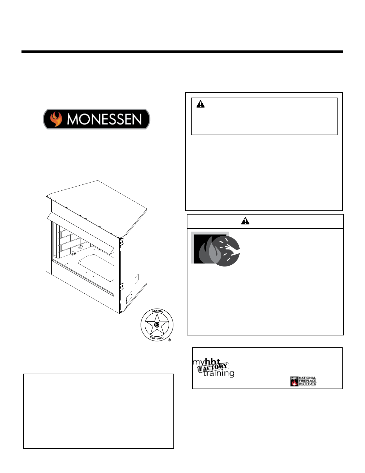
VENT FREE FIREBOX
Model(s):
BUF36, BUF36-R
BUF42, BUF42-R
NOTICE: DO NOT discard this manual!
• DO NOT store or use gasoline or other am-
mable vapors and liquids in the vicinity of this
or any other appliance.
•
DO NOT overre. Overring will void your
warranty.
• Comply with all minimum clearances to com-
bustibles as specied. Failure to comply may
cause house re.
WARNING: If the information in these
instructions is not followed exactly, a re
or explosion may result causing property
damage, personal injury, or death.
WARNING
HOT SURFACES!
Glass and other surfaces are hot during
operation AND cool down.
Hot glass will cause burns.
• DO NOT touch glass until it is cooled
• NEVER allow children to touch glass
• Keep children away
• CAREFULLY SUPERVISE children in same room as
replace.
• Alert children and adults to hazards of high temperatures.
High temperatures may ignite clothing or other ammable
materials.
• Keep clothing, furniture, draperies and other ammable
materials away.
Carefully review the instructions supplied
with the decorative type unvented room
heater for the minimum fireplace size
requirement.
DO NOT INSTALL AN APPLIANCE IN THIS
FIREBOX UNLESS THIS FIREBOX MEETS
THE MINIMUM DIMENSIONS REQUIRED
FOR THE INSTALLATION.
Installation and service of this appliance should
be performed by qualied personnel. Hearth
& Home Technologies recommends HHT
Factory Trained or NFI certied professionals.
1
Monessen • BUF36/42 Installation and Operating Manual • 4600-900 • Rev C • 05/17

Safety Alert Key:
• DANGER! Indicates a hazardous situation which, if not avoided will result in death or serious injury.
• WARNING! Indicates a hazardous situation which, if not avoided could result in death or serious injury.
• CAUTION! Indicates a hazardous situation which, if not avoided, could result in minor or moderate injury.
• NOTICE: Indicates practices which may cause damage to the replace or to property.
Table of Contents
Installation Standard Work Checklist 3
1 Welcome
A. Congratulations 3
B. LIMITED LIFETIME WARRANTY 4
2 Important Safety and Operating Information 5
3 General Installation Information
Before You Start 7
Check Parts 7
Tools Needed for Installation 7
4 Firebox and Framing Dimensions
Dimensions 8
5 Hearth Dimensions and Firebox Locations
Hearth Dimensions 9
Firebox Locations 9
6 Clearances 10
7 Fireplace, Canopy and Gas Line Installation 12
8 Combustion Air 14
Install Model AK22 Combustion Air Assembly 15
9 Optional Equipment
Forced Air Kit 16
10 Service Parts
2
Monessen • BUF36/42 Installation and Operating Manual • 4600-900 • Rev C • 05/17
Customer:
Lot/Address
Model (circle one): BUF36 BUF42
BUF36-R BUF42-R
YES IF NO, WHY?
Wiring has been installed if necessary.
Dealer/Distributor Phone #
Serial #:
Fireplace Install
ATTENTION INSTALLER:
Follow this Standard Work Checklist
This standard work checklist is to be used by the installer in conjuction with, not instead of, the instructions contained in this installation
manual.
Date Installed:
Location of Fireplace:
Installer:
WARNING! Risk of Fire or Explosion! Failure to install fireplace acording to these instructions can lead to a fire or
explosion.
Verified clearances to combustibles. (Pg. 11)
Fireplace is leveled and secured. (Pg. 13)
Hearth extension size/height decided. (Pg. 12)
Outside air kit installed. (Pg 15) Optional
Comments communicated to party responsible
4600-902 • Rev B • 1/17
• Photographing the installation and copying this checklist for your file.
Combustible materials not installed in non-combustible areas.
(Builder/Gen. Contractor) (Installer) (Date)
Comments: Further description of the issues, who is responsible (Installer/Builder/Other Trades, etc.) and corrective action needed:
• That this checklist remain visible at all times on the fireplace until the installation is complete.
__________________________ by ______________________on _________
Hearth extension installed per manual requirements.
Verified all clearances meet installation manual requirements.
Mantels and wall projections comply with installation manual requirements.
Hearth & Home Technologies recommends the following:
Finishing
Fireplace Setup
All packaging and protective materials removed.
Refractory installed correctly. (Optional)BUF36 & BUF42
Firescreen installed properly.
Manual bag and all of its contents are removed from the fireplace and given to the party
responsible for use and operation.
Blower kit installed properly. (Optional)
3
Monessen • BUF36/42 Installation and Operating Manual • 4600-900 • Rev C • 05/17
Read this manual before installing or operating this replace.
Please retain this manual for future references.
A. Congratulations
Congratulations on selecting a Monessen Hearth gas re-
box. It is designed to provide the utmost in safety, reliability,
and efciency.
As the owner of a new replace, you'll want to read and
carefully follow all of the instructions contained in this man-
ual. Pay special attention to all Cautions and Warnings.
This manual should be retained for future reference. We
suggest that you keep it with your other important docu-
ments and product manuals.
Your new Monessen vent-free replace will give you years
of durable use and trouble-free enjoyment. Welcome to the
Monessen family of replace products!
1
Welcome
Monessen is a registered trademark of Hearth & Home
Technologies.
Brand: ________________________________________________ Model Name: ___________________________
Serial Number: __________________________________________ Date Installed: __________________________
Fireplace Information:
Local Dealer Information
DEALER: Fill in
your name, address,
phone and email
information here and
replace information
below.
Dealer Name: ________________________________________________________
Address: ____________________________________________________________
____________________________________________________________
Phone: _____________________________________________________________
Email: _____________________________________________________________
4
Monessen • BUF36/42 Installation and Operating Manual • 4600-900 • Rev C • 05/17

B. LIMITED LIFETIME WARRANTY
The following components are warranted for life to the original owner, subject of proof of purchase:
Firebox, and Combustion Chamber.
BASIC WARRANTY
Monessen warrants the components and materials in your gas appliance to be free from manu-
facturing and material defects for a period of two years from date of installation. After installation,
if any of the components manufactured by Monessen in the appliance are found to be defective in
materials or workmanship, Monessen will, at its option, replace or repair the defective components
at no charge to the original owner. Monessen will also pay for reasonable labor costs incurred
in replacing or repairing such components for a period of two years from the date of installation.
Any products presented for warranty repair must be accompanied by a dated proof of purchase.
This Limited Lifetime Warranty will be void if the appliance is not installed by a qualied installer
in accordance with the installation instructions. The Limited Lifetime Warranty will also be void if
the appliance is not operated and maintained according to the operating instructions supplied with
the appliance, and does not extend to: (1) rebox/burner assembly damage by accident, neglect,
misuse, abuse, alteration, negligence of others, including the installation thereof by unquali-
ed installers, (2) the costs of removal, re-installation or transportation of defective parts on the
appliance; or, (3) incidental or consequential damage. All service work must be performed by an
authorized service representative.
This warranty is expressly in lieu of other warranties, express or implied, including the warranty of
merchantability of tness for purpose and of all other obligations or liabilities. Monessen does not
assume for it any other obligations or liability in connection with the sale or use of the appliance.
In states that do not allow limitations on how long an implied warranty lasts, or do not allow exclu-
sion of indirect damage, those limitations of exclusions may not apply to you. You may also have
additional rights not covered in this Limited Lifetime Warranty.
Monessen reserves the right to investigate any and all claims against the Limited Lifetime Warranty
and decide upon method of settlement.
IF WARRANTY SERVICE IS NEEDED
1. Contact your supplier. Make sure you have your warranty, your sales receipt and the model/
serial number of your Monessen product.
2. DO NOT ATTEMPT TO DO ANY SERVICE WORK YOURSELF.
5
Monessen • BUF36/42 Installation and Operating Manual • 4600-900 • Rev C • 05/17
Continued on page 7
INSTALLER
Please leave these instructions with the appliance.
OWNER
Please retain these instructions for future reference
.
WARNING!
• Any change to this heater or its controls can be dangerous.
• Improper installation or use of the heater can cause serious injury or death from re, burns,
explosion or carbon monoxide poisoning.
• Do not allow fans to blow directly into the replace. Avoid any drafts that alter burner ame patterns.
• Do not use a blower insert, heat exchanger insert or other accessory, not approved for
use with this heater where applicable.
1. Due to high temperatures, the rebox should be
located out of trafc and away from furniture and
draperies.
2. Children and adults should be alerted to the hazard
of high surface temperature and should stay away
to avoid burns or clothing ignition.
3. Young children should be carefully supervised when
they are in the same room with the rebox.
4. Do not place clothing or other ammable material
near the replace when the rebox is in use.
5. Any safety screen or guard removed for servicing,
must be replaced prior to operating a heater within
the rebox.
6. Installation and repair should be done by a qualied
service person.
7. To prevent malfunction and/or sooting, an unvented
gas heater/rebox should be cleaned at least annu-
ally by a professional service person. More frequent
cleaning may be required due to excessive lint from
carpeting, etc. It is imperative that control compart-
ments, burners and circulating air passageways be
kept clean.
8. CARBON MONOXIDE POISONING: Early signs of
carbon monoxide poisoning are similar to the u with
headaches, dizziness and/or nausea. If you have these
signs, obtain fresh air immediately. Have the heater
serviced as it may not be operating properly.
9. The installation must conform with local codes or, in
the absence of local codes, with the National Fuel Gas
Code, ANSI Z223.l/NFPA54.
10. This unit complies with ANSI Z21.91 ventless rebox
enclosures for gas-red unvented decorative room
heaters.
11. Do not install the unvented heater in a bathroom.
12. Do not install the unvented heater in a bedroom unless
the maximum input rating is equal to or less than
10,000 Btu/hr.
13. Correct installation of the ceramic ber logs, proper
location of the heater, and annual cleaning are neces-
sary to avoid potential problems with sooting. Sooting,
resulting from improper installation or operation, can
settle on surfaces outside the replace. See log place-
ment instructions for proper installation.
14. Avoid any drafts that alter burner ame patterns. Do not
allow fans to blow directly into replace. Do not place
a blower inside burn area of rebox. Ceiling fans may
create drafts that alter burner ame patterns. Sooting
and improper burning will occur.
15. CAUTION: Candles, incense, oil lamps, etc. produce
combustion byproducts including soot. Vent-free
appliances will not lter or clean soot produced by
these types of products. In addition, the smoke and/
or aromatics (scents) may be re-burnt in the vent-free
appliance which can produce odors. It is recommended
to minimize the use of candles, incense, etc. while the
vent-free appliance is in operation.
16. An unvented gas-red heater uses air (oxygen) from
the room in which it is installed. Provisions for adequate
combustion and ventilation air must be provided. See
installation guidelines.
17. Keep room area clear and free from combustible mate-
rials, gasoline and other ammable vapors and liquids.
18. Unvented gas heaters are a supplemental zone heater.
They are not intended to be a primary heating appli-
ance.
19. Unvented gas heaters emit moisture into the living
area. In most homes of average construction, this
does not pose a problem. In houses of extremely
tight construction, additional mechanical ventilation is
recommended.
20. During manufacturing, fabricating and shipping, various
components of this appliance are treated with certain
oils, lms or bonding agents. These chemicals are not
harmful but may produce annoying smoke and smells
as they are burned off during the initial operation of the
appliance; possibly causing headaches, or eye or lung
irritation. This is a normal and temporary occurrence.
2
Important Safety and Operating Information
6
Monessen • BUF36/42 Installation and Operating Manual • 4600-900 • Rev C • 05/17
WARNING!
Do not attempt to burn solid wood fuels, vented
gas log sets, or any other combustible in this
unvented rebox. Also, do not install a vent-
free gas log set in this rebox if the minimum
clearance and height requirements of the log
set are too large for the rebox.
Continued from page 6
The initial break-in operation should last two to three
hours with the burner at the highest setting. Provide
maximum ventilation by opening windows or doors to
allow odors to dissipate. Any odors remaining after this
initial break-in period will be slight and will disappear
with continued use.
21. Input ratings are shown in BTU per hour and are for
elevations up to 2,000 feet. For elevations above 2,000
feet, input ratings should be reduced 4 percent for each
1,000 feet above sea level. Refer to the National Fuel
Gas Code.
22. The appliance and its main gas valve must be discon-
nected from the gas supply piping system during any
pressure testing of that system at test pressures in
excess of 1/2 psig (3.5 kPa).
23. The appliance must be isolated from the gas supply
piping system by closing its equipment shutoff valve
during any pressure testing of the gas supply piping
system at test pressures equal to or less than 1/2 psig
(3.5 kPa).
24. Do not use this room heater if any part has been under
water. Immediately call a qualied service technician
to inspect the room heater and to replace any part of
the control system and any gas control which has been
under water.
25. Never burn solid fuels in a replace where a unvented
room heater is installed.
26. Always have a replace screen in place when the
appliance is in operation, and unless other provisions
for combustion air are provided, the screen shall have
an opening(s) for induction of combustion air.
27. Do not ll spaces around the rebox with insulation or
other materials. These spaces must be maintained to
prevent the rebox from coming in contact with com-
bustible materials.
Notice: Illustrations shown in this manual reect
“typical” installations with nominal dimensions and
are for design and framing reference only. Actual
installations may vary due to individual design
preferences. However, always maintain minimum
clearances to combustible materials and do not
violate any specic installation requirements.
WARNING!
Never connect unit to private (non-utility)
gas wells. This gas is commonly known as
wellhead gas.
Nous recommandons que nos
appareils de chauffage au gaz
soient installés et entretenus par
des professionnels qui ont été
accrédités aux È.U. par le National
Fireplace Institute ® (NFI) comme
étant des spécialistes du NFI en
matièred’appareils de chauffage
au gaz.
7
Monessen • BUF36/42 Installation and Operating Manual • 4600-900 • Rev C • 05/17

3
General Installation Information
The new BUF36, BUF36-R, BUF42, AND BUF42-R are
vent free reboxes. They feature a self contained heat-
circulating system.
This installation manual will enable you to obtain a safe,
efcient and dependable installation of your vent-free
replace system.
Do not alter or modify the rebox or its components under
any circumstances. Any modication or alteration of the
rebox system, including but not limited to the rebox and
accessories, may void the warranty, listings and approvals
of this system and could result in an unsafe and potentially
dangerous installation.
BEFORE YOU START
Carefully inspect the contents for shipping damage. If any
parts are missing or damaged, immediately inform the
dealer from whom you purchased the appliance. Do not
attempt to install any part of the appliance unless you have
all the parts in good condition.
Note: If using a blower, electrical connections should
be made prior to the rebox being enclosed by the
nished walls.
MAKE SURE YOU HAVE RECEIVED ALL
PARTS
Verify contents to ensure all parts have been received.
The following should be included:
1. Vent Free Gas Firebox
2. Canopy
3. Installation and Operating Instructions
4. Three (3) sheet metal screws for canopy
WHAT YOU WILL NEED FOR INSTALLATION
TOOLS and BUILDING SUPPLIES
• Phillips screwdriver • Square
• Framing materials • Hammer
• Saw and / or saber saw • Tee joint
• Level • Pipe wrench
• Measuring tape • Pliers
• Electric drill and bits
• Fireplace surround materials (noncombustible)
• Caulking material (noncombustible)
• Wall nishing materials
• Piping complying with local codes
• Pipe sealant approved for use with propane/L.P.G.
(resistant to sulfur compounds)
Refer to the installation instructions provided with the log
sets for items required for log set installation.
In planning the installation for the appliance it is necessary
to determine where the unit is to be installed and whether
optional accessories are desired. Gas supply piping should
also be planned. The following steps represent the normal
sequence of installation. Each installation is unique, how-
ever, and might require a different sequence.
1. Position rebox prior to framing or into prepared framing.
2. The canopy supplied with the unit must be installed.
See Canopy Installation on page 13.
3. Field wire main power supply to models with fan kit.
(Electrical connections should only be performed by an
experienced, licensed /certied tradesman).
4. Plumb gas line. (Gas connections should only be per-
formed by an experienced, licensed/certied trades-
man).
5. Install vent-free gas log heater per the instructions
provided with the vent-free gas log heater.
6. Complete nish wall material, surround and optional
hearth extension to your individual taste.
8
Monessen • BUF36/42 Installation and Operating Manual • 4600-900 • Rev C • 05/17
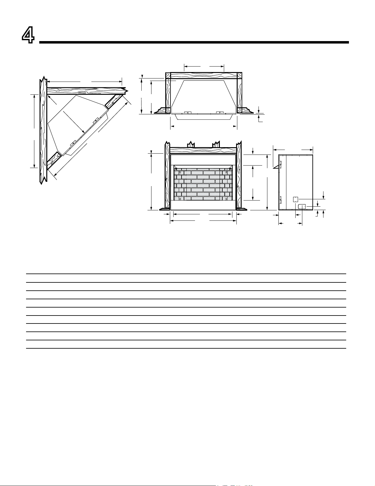
4
Firebox and Framing Dimensions
B
A
Rough
Opening
Height
C
23"
Rough
Opening
Depth
D - Rough Opening Width
1/2" - 5/8"
23-1/4"
F
E
E
G
611013
BUF dims
I
6-1/8"
37-1/2"
24"
25-1/4"
J
8-3/4"
7"
37-1/4"
3"
3"
3-3/4"
13-3/4"
7-1/8"
Ref. BUF36, BUF36-R BUF42, BUF42-R
A 42" 48"
B 36" 42"
C 28-1/4" 30-3/4"
D - Chase Installation 42-1/2" 48-1/2"
D - Recessed Installation 42-3/4" 48-3/4"
E 52" 56-5/8"
F 71-1/2" 74-1/2"
G 36-3/4" 38-7/8"
Figure 4.1 Firebox and Framing Dimensions
9
Monessen • BUF36/42 Installation and Operating Manual • 4600-900 • Rev C • 05/17
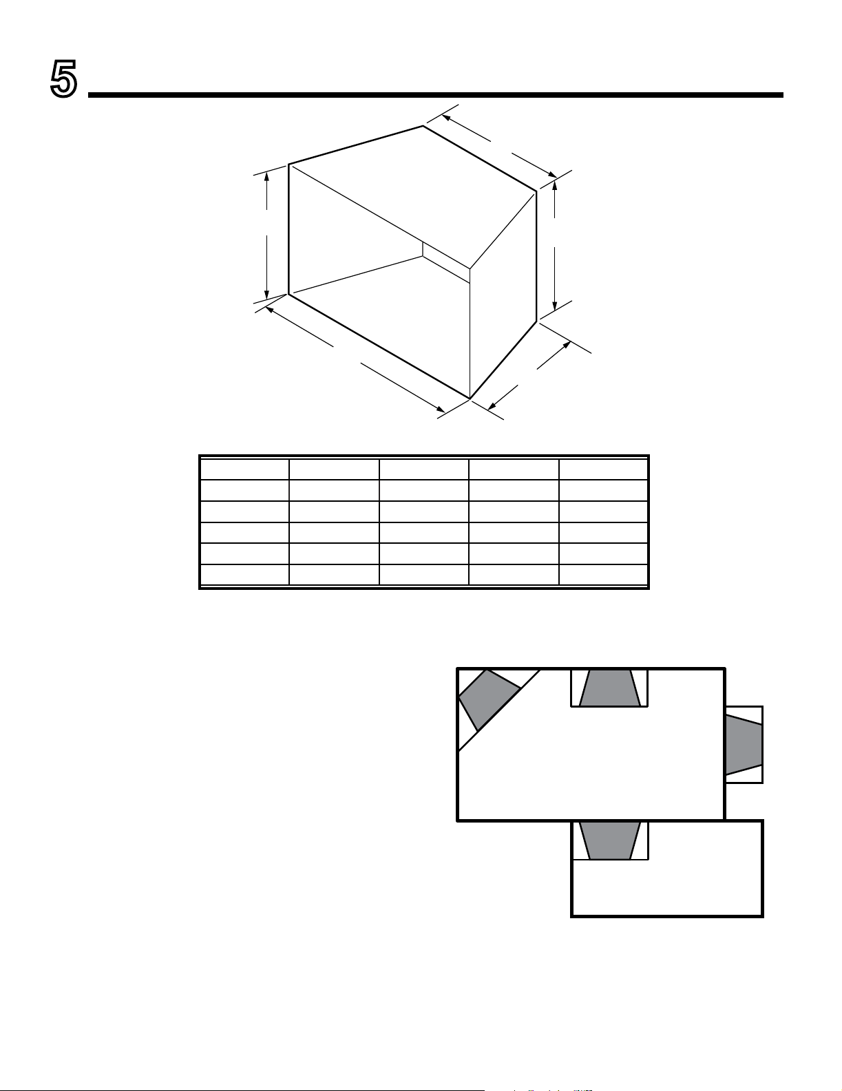
5
Hearth Dimensions and Firebox Locations
A
B
C
D
E
FP2901
hearth dims
FIREBOX LOCATION
Carefully select the best location for installation of your
vent-free rebox. The following factors should be taken
into consideration:
• Clearance to side wall, ceiling, woodwork and windows.
See “Clearances/Height Requirements on page 8. Mini-
mum clearances to combustibles must be maintained.
• Location must not be affected by drafts caused by
kitchen exhaust fans, ceiling fans, return air registers for
forced air furnaces / air conditioners, windows or doors.
• Installation must provide adequate ventilation and com-
bustion air.
• Location should be out of high trafc or windy or drafty
areas.
• DO NOT INSTALL WHERE CURTAINS, FURNITURE,
CLOTHING OR OTHER FLAMMABLE OBJECTS ARE
LESS THAN 42" FROM FRONT OF HEATER.
• Never obstruct the front opening of the vent-free rebox
or restrict the ow of combustion and ventilation air.
• Minimize modications to existing construction. Refer
to Figure 5.2 for location suggestions.
• Do not install in the vicinity where gasoline or other
ammable liquids may be stored. The vent free rebox
must be kept clear and free from these combustible
materials.
FP2440
fireplace locations
Figure 5.1 Minimum Hearth Dimensions
Figure 5.2 Location of Firebox
Ref. BUF36 BUF36-R BUF42 BUF42-R
A 35-1/4" 33-3/4" 41-1/4" 39-3/4"
B 18-5/8" 17-7/8" 18-5/8" 17-7/8"
C 27-1/4" 25-3/4" 30-1/4" 28-3/4"
D 21-3/4" 21-3/4" 21-3/4" 21-3/4"
E 20-3/8" 20-3/8" 20-3/8" 20-3/8"
10
Monessen • BUF36/42 Installation and Operating Manual • 4600-900 • Rev C • 05/17
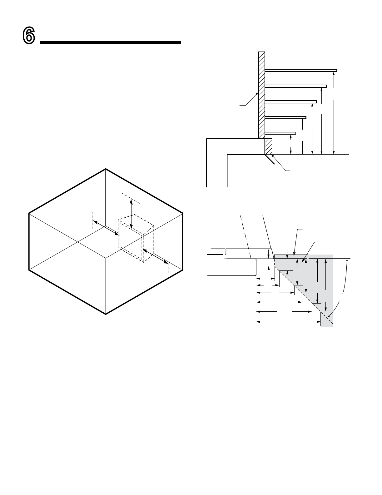
6
Clearances
Ensure that minimum clearances shown in Figures 6.1
through 6.3 are maintained. Left and right clearances are
determined when facing the front of the rebox.
Follow these instructions carefully to ensure safe instal-
lation. Failure to follow these requirements may create a
re hazard.
1. Sidewall clearances: The clearance from the inside
of the appliance to any combustible wall should not be
less than 9". See Figure 6.1.
2. Ceiling clearance: The ceiling must be at least 42"
from the top of the rebox opening. See Figure 6.1.
3. Back wall clearance: The appliance may be placed
against a combustible back wall.
9"
Minimum
42"
Minimum
9"
Minimum
FP2687
minimum clearances
FP2687
4. Mantel clearances: If a combustible mantel is installed,
it must meet the clearance requirements as shown in
Figures 6.2 & 6.3.
12”
10”
8”
6”
2¹⁄₂”
12”
16”
19”
21”
23”
FP2690
Mantel clearances
Combustible
Material Can
Contact Top
of Fireplace
FP2690
Noncombustible Material
Only if Needed to Cover
Radiant Top Face
45°
1”
2¹⁄₂”
3”
5”
6”
1¹⁄₂”
3¹⁄₂”
4¹⁄₂”
FP2692
mantel leg clearance
6”
7¹⁄₂”
7¹⁄₂”
9”
Finish Wall
Combustible
Material Area
FP2692
NOTE: The canopy supplied with the unit must be installed
for correct mantel clearances.
Figure 6.1 Clearance and Height Requirements
Figure 6.2 Mantel Clearances
Figure 6.3 Mantel Leg Clearance
11
Monessen • BUF36/42 Installation and Operating Manual • 4600-900 • Rev C • 05/17
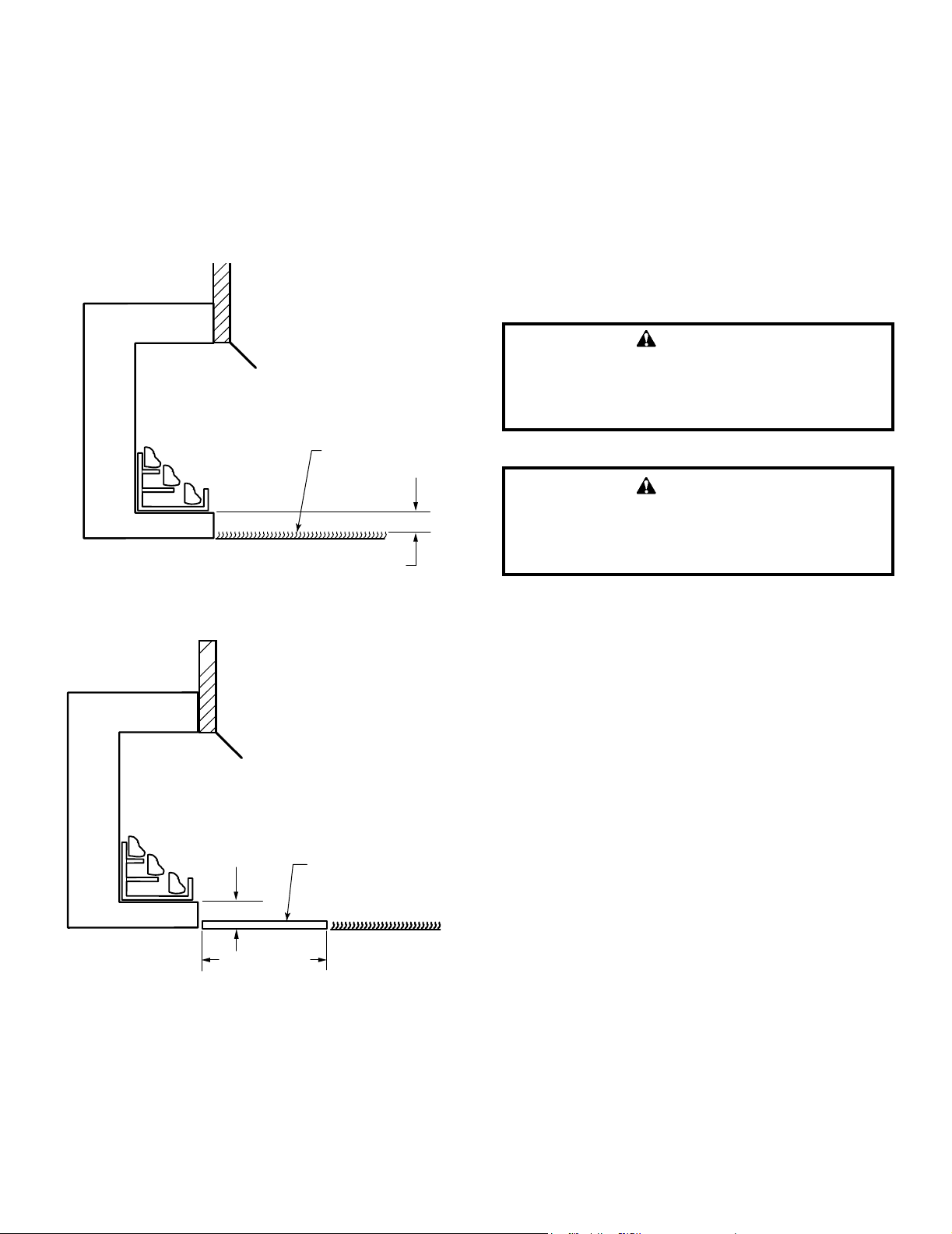
5. Floor clearance: This inner chamber rebox oor must
be installed at least 5" above any combustible ooring
material, such as carpeting or asphalt tile, which is closer
than 14" to the base of the rebox. See Figure 6.4.
Or
The inner chamber rebox oor may be installed nearer to
the oor if a minimum of 14" of noncombustible material
such as slate or marble is installed between the base of
the rebox and the combustible ooring. See Figure 6.5.
FP2688
min floor combustible
5" Minimum
Combustible
Material
FP2688
14” Minimum
FP2689
min floor clear noncomb
Can be Less
Than 5"
Noncombustible
Material
FP2689
Figure 6.4 Minimum Clearance Above Combustible Flooring
Figure 6.5 Minimum Clearance Above Combustible Flooring with
Noncombustible Material Installed at Base of Fireplace
Firebox framing can be built before or after the appliance is
set in place. Construct rebox framing following Figure 4.1
for your specic installation requirements. Refer to Figure
4.1 on page 9 for rebox dimensions. The framing headers
may rest on the top of the rebox standoffs.
The rebox may be installed directly on a combustible oor
or raised on a platform of an appropriate height. When
the rebox is installed directly on carpeting, tile, or other
combustible material, other than wood ooring, the rebox
shall be installed on a metal or wood panel extending the
full width and depth of the enclosure.
WARNING!
Do not ll spaces around rebox with insulation
or other materials. This could cause a re.
WARNING!
The fireplace must be installed giving full
consideration to the clearance and height
requirements identied in this manual.
12
Monessen • BUF36/42 Installation and Operating Manual • 4600-900 • Rev C • 05/17
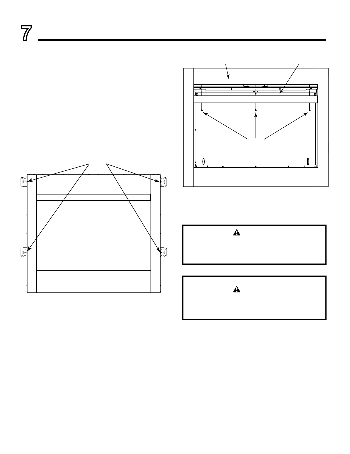
SECURING AND LEVELING THE APPLIANCE
1. Bend out the nailing anges located on each side of the
rebox.
2. Slide the rebox into prepared framing or position rebox
in its nal position and frame later.
3. Level the rebox by checking the top edge of the rebox.
Shim if necessary.
4. Anchor rebox to the side framing members using 8d
nails or other suitable fasteners. Figure 7.1
5. The canopy must be installed for safe operation of the
rebox.
CANOPY INSTALLATION
A canopy is furnished with each rebox and MUST be
installed for safe operation.
1. Locate three (3) holes (one at each end and one in
center) of canopy and attach to face of unit with supplied
screws. Figure 7.2.
WARNING!
The rebox canopy must not be modied or
replaced with a canopy that may be provided
with the vent free decorative room heater.
WARNING!
Close replace screen panel before operating a
decorative type vent free room heater.
7
Fireplace, Canopy and Gas Line Installation
Figure 7.1 Location of Nailing Flanges
Figure 7.2 Canopy Installation
Nail Sides Through Nailing Flanges
Screws
Front Face Canopy
13
Monessen • BUF36/42 Installation and Operating Manual • 4600-900 • Rev C • 05/17
Consult all local codes. All gas piping must be installed to
comply with local codes, or in the absence of local codes,
with the latest edition of the National Fuel Gas Code ANSI
Z223.1/NFPA54.
The 1/2" gas line may enter either from the left side or right
side of the rebox. Gas access holes are provided on both
sides of the rebox.
A listed manual shutoff valve must be installed upstream of
the appliance. A union tee and plugged 1/8" NPT pressure
tapping point should be installed upstream of the appliance.
IMPORTANT: Install main gas valve (equipment shutoff
valve) in an accessible location. The main gas valve is
for turning on or shutting off the gas to the replace.
A sediment trap may be upstream of the heater to prevent
moisture and contaminants from passing through trap to
the heater controls and burners. Failure to do so could
prevent the heater from operating reliably. Consult appli-
cable codes.
An external regulator must be used on all propane/L.P.G.
heaters, in addition to the regulator tted to the heater, to
reduce the supply tank pressure to 13" w.c. (maximum).
Any copper tubing used to supply propane / L.P.G. from
the tank must be internally tinned.
NOTE: When connecting propane / L.P.G. vent-free
room heaters, you must use pipe sealant resistant to
propane / L.P.G.
IMPORTANT: Hold heater regulator with a wrench to
prevent movement when connecting to inlet piping.
Check gas type: The gas supply must be the same as
stated on the heater’s rating plate. If the gas supply
is different, DO NOT INSTALL THE HEATER. Contact
your dealer for the correct model.
Notice: After completing connection, test all gas joints
from the gas meter to the gas heater regulator for leaks.
Using soap and water solution or a gas sniffer. DO NOT
USE AN OPEN FLAME.
WARNING!
Plumbing connections should only be
performed by a qualied, licensed plumber.
Main gas supply must be off when plumbing
gas line to replace or performing service.
WARNING!
Connecting directly to an unregulated propane
/ L.P.G. tank can cause an explosion.
WARNING!
Do not connect directly to natural gas 1/2 PSI or
2 PSI systems. Always make sure natural gas
pressure is regulated 10.5 w.c. (maximum before
operating the unit).
GAS CONNECTIONS
14
Monessen • BUF36/42 Installation and Operating Manual • 4600-900 • Rev C • 05/17
8
Combustion Air
AK22 INSTALLATION
Note: The AK22 is an optional accessory that can be used
to bring in fresh air. Use of the AK22 is not required for
operation unless specied by local codes.
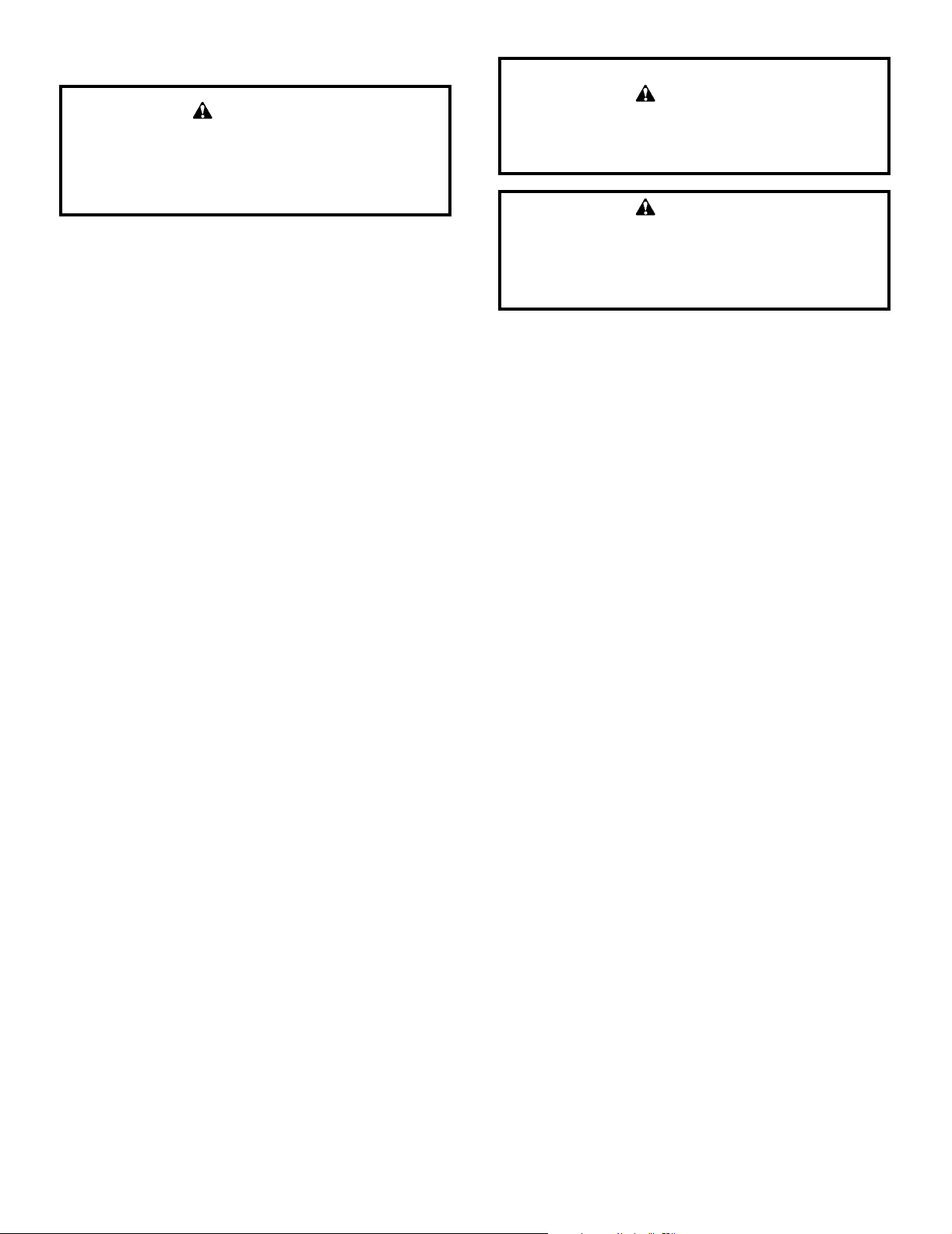
1. Locate combustion air assembly at an exterior location
which is not likely to be accidentally blocked in any man-
ner. Locate assembly a min. of 12" above the snow line
to prevent blockage by snow accumulation.
2. Never mount the combustion air inlet assembly in a ga-
rage or storage area where combustible fumes such as
gasoline might be drawn into the replace.
3. Combustion air can be drawn from the crawl space under
a house when an adequate supply of air is provided by
open ventilation.
4. CAUTION: Do not take combustion air from attic space
or garage space.
5. Locate air supply inlet at least 3' away from any appliance
vent terminal.
6. Avoid extremely long runs and numerous turns in the duct
leading from the replace to the combustion air assembly.
These conditions increase the resistance to the free ow
of air through the duct. Refer to Figures 8.1 through 8.4
for methods of installing the outside air for combustion
assemblies.
FP2459
OA basement install
Above
Snow
Level
Ground
Level
FP2459
15' Max.
FP2460
OA slab install
Inlet Grille
in Soft
(Overhang)
FP2460
FP2461
above basement
Duct
Extended
to Miss
Joist
FP2461
To Outside Wall
NOTE: Fireplace model in illustrations may not be
representative of your appliance.
Figure 8.1 Basement Installation
Figure 8.2 Concrete Slab Installation (Optional Outside Air Runs)
Figure 8.3 Installation Above Basement or Crawl Space
15
Monessen • BUF36/42 Installation and Operating Manual • 4600-900 • Rev C • 05/17
FP2462
OA corner install
Outside
Wall
Inside Wall
FP2462
Figure 8.4 45° Corner Installation on Slab Floor
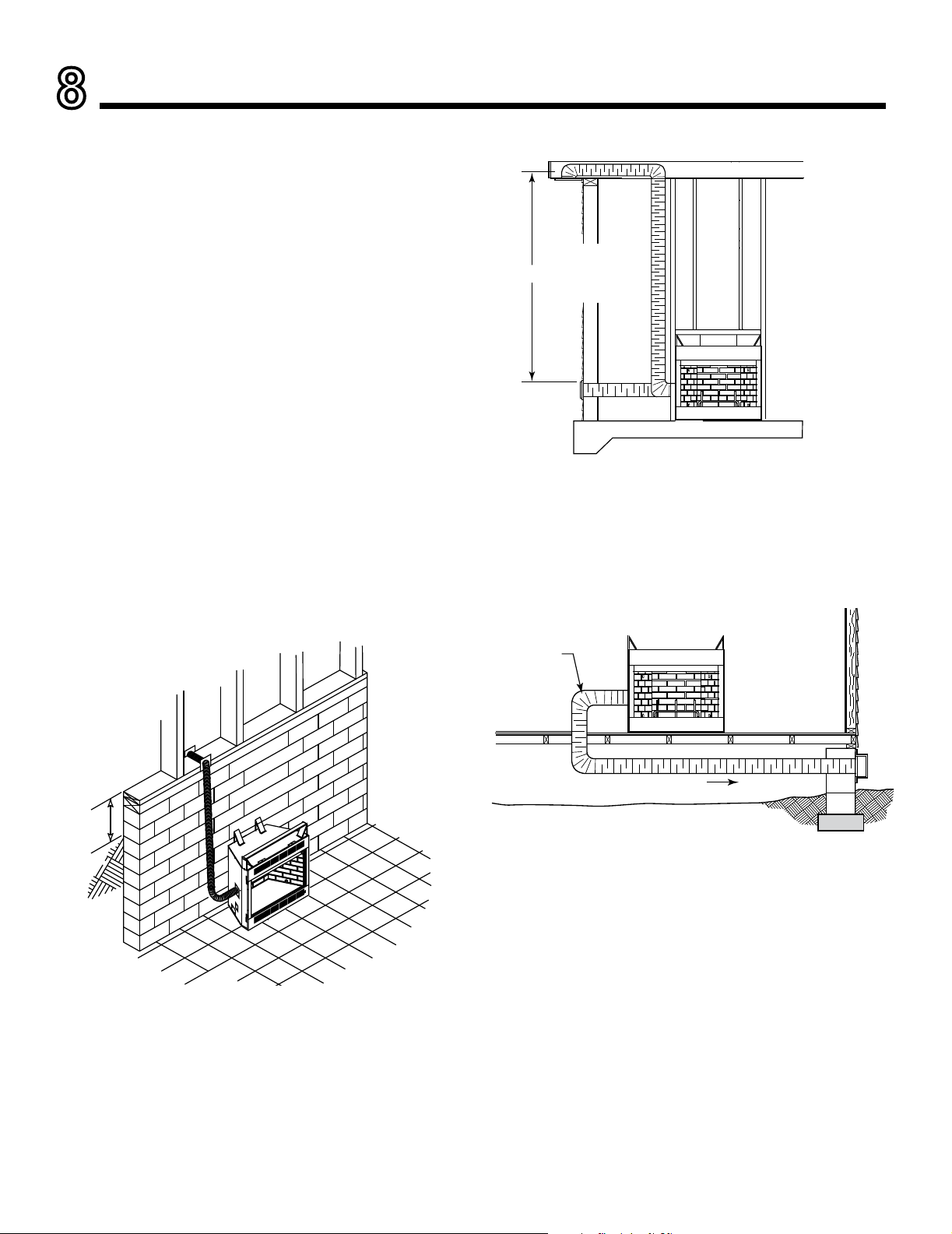
WARNING!
DO NOT remove the cover on side of rebox if
the outside air will not be connected.
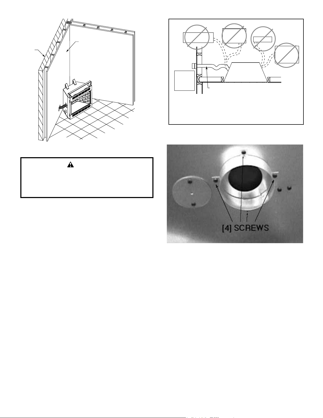
Step by Step Installation
1. Attach the collar to the side of the replace by aligning the
four holes in the collar with the four holes on the replace
side. Attach with the screws provided. See Figure 8.6.
2. Mark and cut out a 4 in. (102 mm) hole in the building
side for air entry. This hole should allow for some framing
(two sides) so the hooded air inlet may be nailed into
position, ush with the building’s outside.
3. Install hooded air inlet in the sidewall of the structure.
4. Assemble the exible duct ID4 or UD4 (not supplied)
between the collar and the hooded air inlet. Secure it
into position with the supplied wire ties.
Outlet placed
higher than 3 ft
below the
termination cap
Attic space
Garage or
combustible
liquids storage
Outlet blocked by
snow, leaves, etc.
Clear area
outside
house or in
ventilated
crawl space
YES
NO
NO
NO
NO
Factory-built
fireplace
• Use UL181 Class 1 or Class 0 rigid or flexible ducting.
• Install with short run or mainly straight duct, except small
dip for cold air trap which will help prevent flow of cold air.
• Secure flex duct with screws or wire ties.
Figure 8.5
Figure 8.6
16
Monessen • BUF36/42 Installation and Operating Manual • 4600-900 • Rev C • 05/17
9
Optional Equipment
FORCED AIR KIT (BLOTMC)
If you are installing the forced air kit, Model BLOTMC, see
the installation instructions provided with the kit for electri-
cal wiring requirements. The rebox must be connected to
main power supply at time of rebox installation. The blower
must be installed prior to the installation of the vent-free
heater. The electrical connections must be made before
the rebox is framed and enclosed in the nished walls.
WARNING!
Electrical connections should only be performed
by a qualied, licensed electrician, main power
must be off when connecting to main electrical
power supply or performing service.
When installed, the blower must be electrically
grounded in accordance with local codes or in
the absence of local codes, with the National
Electrical Code ANSI/NFPA 70.
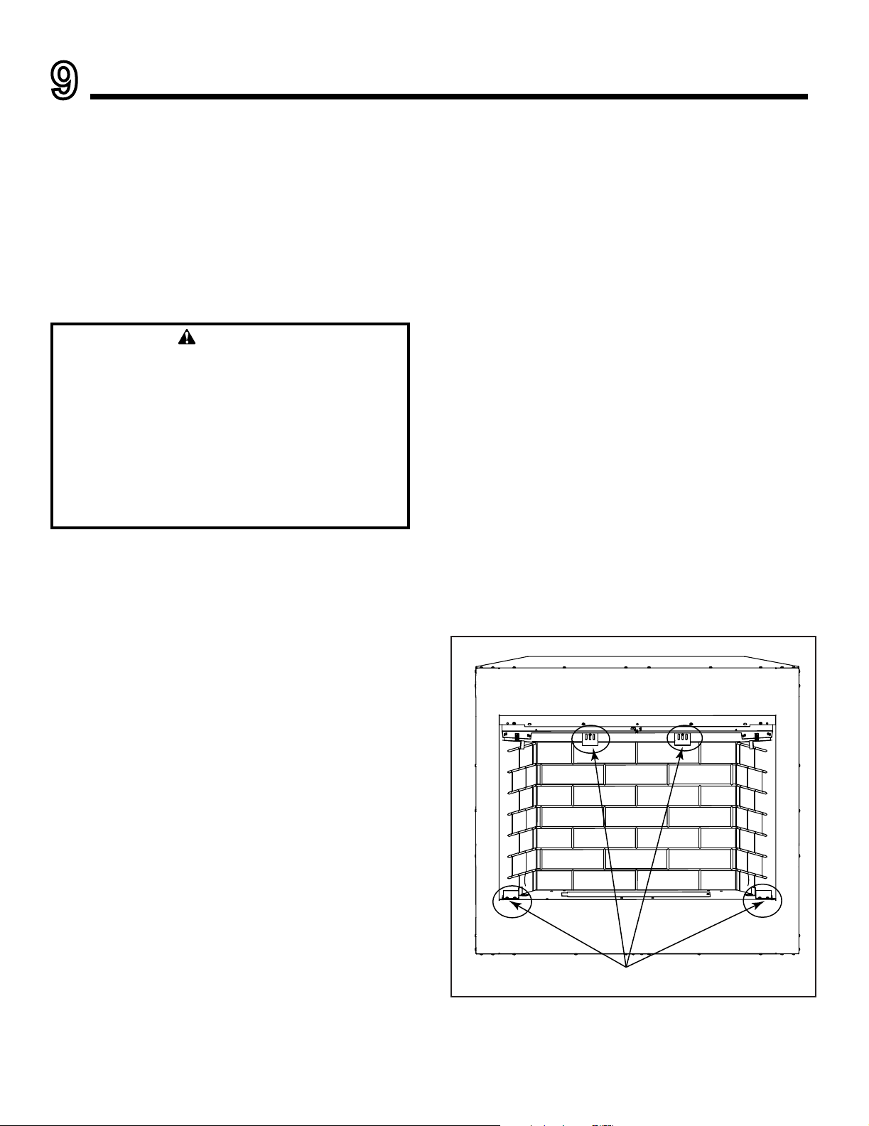
REFRACTORY
Optional refractory panels (left, right and back) may be
installed in the BUF36 and BUF42. (NOTE: The BUF36-
R and BUF42-R models come standard with refractory
installed.) If refractory is being installed, please refer to the
rebrick liner kit installation instructions provided with the
refractory panels for more information.
For BUF36-R and BUF42-R refractory panels are shipped
installed. Once unit is in place, remove the shipping brack-
ets from the rear brick panel (leave screws in place) and
the brackets from the left and right front. NOTE: Brackets
located on top and bottom of side panels remain in place.
See Figure 9.1.
Brackets to be removed before operation.
Figure 9.1
17
Monessen • BUF36/42 Installation and Operating Manual • 4600-900 • Rev C • 05/17
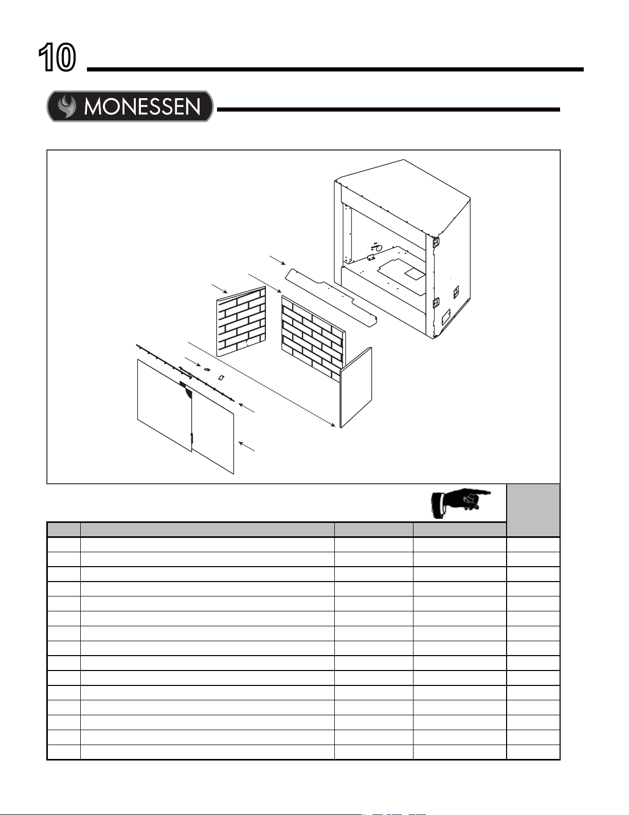
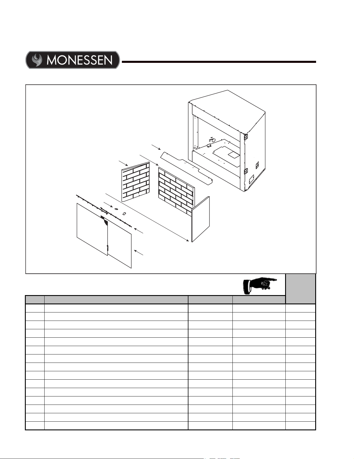
10
Service Parts
Service Parts
BUF36
Beginning Manufacturing Date: Jan 2017
Ending Manufacturing Date: Active
IMPORTANT: THIS IS DATED INFORMATION. Parts must be ordered from a dealer or distributor. Hearth and
Home Technologies does not sell directly to consumers. Provide model number and serial number when
requesting service parts from your dealer or distributor.
Stocked
at Depot
ITEM DESCRIPTION COMMENTS PART NUMBER
1 Canopy
SRV4600-107
Refractory Assembly
FBBUF36R
2 Rear Refractory
SRV4600-700
3 Left Refractory
SRV4600-701
4 Right Refractory
SRV4600-702
5 Screen Assembly Spacer
Qty 2 req SRV4600-109 Y
6 Screen Panel
Qty 2 req SRV4600-020 Y
Handle, Screen
10002
Firescreen Ring
Qty 9 req 11857B
7 Screen Rod
Qty 2 req 12052 Y
Junction Box
21878
Junction Box Cover Plate
Qty 3 req 26548
Junction Box Bracket
4049-176
Nailing Flange
Qty 4 req 31190
Outside Air Kit
AK22
Additional service part numbers on following page. 12/16
1
2
3
4
5
6
7
18
Monessen • BUF36/42 Installation and Operating Manual • 4600-900 • Rev C • 05/17
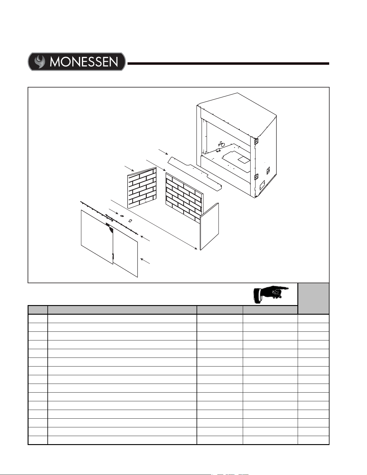
Service Parts
BUF36-R
Beginning Manufacturing Date: Jan 2017
Ending Manufacturing Date: Active
IMPORTANT: THIS IS DATED INFORMATION. Parts must be ordered from a dealer or distributor. Hearth and
Home Technologies does not sell directly to consumers. Provide model number and serial number when
requesting service parts from your dealer or distributor.
Stocked
at Depot
ITEM DESCRIPTION COMMENTS PART NUMBER
1 Canopy
SRV4600-107
Refractory Assembly
FBBUF36R
2 Rear Refractory
SRV4600-700
3 Left Refractory
SRV4600-701
4 Right Refractory
SRV4600-702
5 Screen Assembly Spacer
Qty 2 req SRV4600-109 Y
6 Screen Panel
Qty 2 req SRV4600-020 Y
Handle, Screen
10002
Firescreen Ring
Qty 9 req 11857B
7 Screen Rod
Qty 2 req 12052 Y
Junction Box
21878
Junction Box Cover Plate
Qty 3 req 26548
Junction Box Bracket
4049-176
Nailing Flange
Qty 4 req 31190
Outside Air Kit
AK22
1/17
1
2
3
4
5
6
7
19
Monessen • BUF36/42 Installation and Operating Manual • 4600-900 • Rev C • 05/17
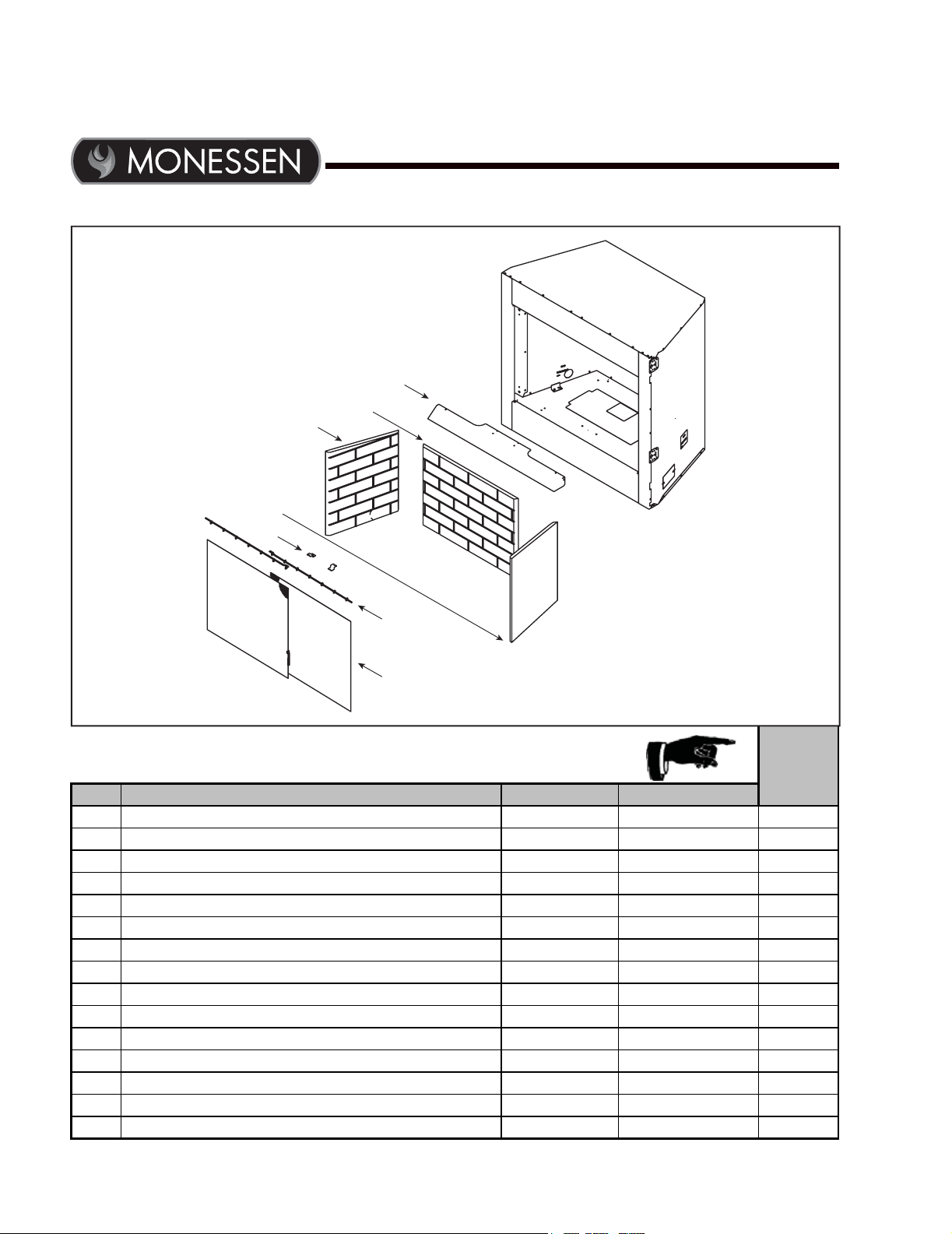
Service Parts
BUF42
Beginning Manufacturing Date: Jan 2017
Ending Manufacturing Date: Active
IMPORTANT: THIS IS DATED INFORMATION. Parts must be ordered from a dealer or distributor. Hearth and
Home Technologies does not sell directly to consumers. Provide model number and serial number when
requesting service parts from your dealer or distributor.
Stocked
at Depot
ITEM DESCRIPTION COMMENTS PART NUMBER
1 Canopy
SRV4603-107
Refractory Assembly
FBBUF42R
2 Rear Refractory
SRV4603-700
3 Left Refractory
SRV4600-701
4 Right Refractory
SRV4600-702
5 Screen Assembly Spacer
Qty 2 req SRV4600-109 Y
6 Screen Panel
Qty 2 req SRV4603-020 Y
Handle, Screen
10002
Firescreen Ring
Qty 9 req 11857B
7 Screen Rod
Qty 2 req 12052 Y
Junction Box
21878
Junction Box Cover Plate
Qty 3 req 26548
Junction Box Bracket
4049-176
Nailing Flange
Qty 4 req 31190
Outside Air Kit
AK22
Additional service part numbers on following page. 12/16
1
2
3
4
5
6
7
20
Monessen • BUF36/42 Installation and Operating Manual • 4600-900 • Rev C • 05/17
Service Parts
BUF42-R
Beginning Manufacturing Date: Jan 2017
Ending Manufacturing Date: Active
IMPORTANT: THIS IS DATED INFORMATION. Parts must be ordered from a dealer or distributor. Hearth and
Home Technologies does not sell directly to consumers. Provide model number and serial number when
requesting service parts from your dealer or distributor.
Stocked
at Depot
ITEM DESCRIPTION COMMENTS PART NUMBER
1 Canopy
SRV4603-107
Refractory Assembly
FBBUF42R
2 Rear Refractory
SRV4603-700
3 Left Refractory
SRV4600-701
4 Right Refractory
SRV4600-702
5 Screen Assembly Spacer
Qty 2 req SRV4600-109 Y
6 Screen Panel
Qty 2 req SRV4603-020 Y
Handle, Screen
10002
Firescreen Ring
Qty 9 req 11857B
7 Screen Rod
Qty 2 req 12052 Y
Junction Box
21878
Junction Box Cover Plate
Qty 3 req 26548
Junction Box Bracket
4049-176
Nailing Flange
Qty 4 req 31190
Outside Air Kit
AK22
1/17
1
2
3
4
5
6
7
21
Monessen • BUF36/42 Installation and Operating Manual • 4600-900 • Rev C • 05/17

C. Contact Information
– NOTES –
Monessen, a brand of Hearth & Home Technologies
7571 215th Street West, Lakeville, MN 50044
www.monessenhearth.com
22
Monessen • BUF36/42 Installation and Operating Manual • 4600-900 • Rev C • 05/17