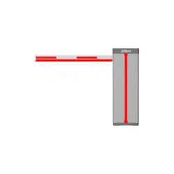

Parking Barrier
User's Manual
ZHEJIANG DAHUA VISION TECHNOLOGY CO., LTD. V1.0.1
User's Manual
I
Foreword
General
This manual introduces the structure, installation, and maintenance of the parking barrier
(hereinafter referred to as the "Barrier"). Read carefully before using the device, and keep the manual
safe for future reference.
Models
Series Model
DHI-IPMECD-3021
DHI-IPMECD-3021-RM1515-T09
DHI-IPMECD-3021-LM1515-T09
DHI-IPMECD-3021-RM1525-T20
DHI-IPMECD-3011-LM1525-T20
DHI-IPMECD-3021-RM1515-T09-AC110
DHI-IPMECD-3021-LM1515-T09-AC110
DHI-IPMECD-3021-RM1525-T20-AC110
DHI-IPMECD-3021-LM1525-T20-AC110
DHI-IPMECD-3022
DHI-IPMECD-3022-RM30-T09
DHI-IPMECD-3022-LM30-T09
DHI-IPMECD-3022-RM40-T20
DHI-IPMECD-3022-LM40-T20
DHI-IPMECD-3022-RM50-T30
DHI-IPMECD-3022-LM50-T30
DHI-IPMECD-3022-RM60-T30
DHI-IPMECD-3022-LM60-T30
DHI-IPMECD-3022-RM30-T09-AC110
DHI-IPMECD-3022-LM30-T09-AC110
DHI-IPMECD-3022-RM40-T20-AC110
DHI-IPMECD-3022-LM40-T20-AC110
DHI-IPMECD-3022-RM50-T30-AC110
DHI-IPMECD-3022-LM50-T30-AC110
DHI-IPMECD-3022-RM60-T30-AC110
DHI-IPMECD-3022-LM60-T30-AC110
Safety Instructions
The following signal words might appear in the manual.
User's Manual
II
Signal Words Meaning
Indicates a high potential hazard which, if not avoided, will result in
death or serious injury.
Indicates a medium or low potential hazard which, if not avoided,
could result in slight or moderate injury.
Indicates a potential risk which, if not avoided, could result in
property damage, data loss, reductions in performance, or
unpredictable results.
Provides methods to help you solve a problem or save time.
Provides additional information as a supplement to the text.
Revision History
Version Revision Content Release Date
V1.0.1 Updated wiring diagram and inverter descriptions. January 2022
V1.0.0 First release. December 2021
Privacy Protection Notice
As the device user or data controller, you might collect the personal data of others such as their face,
fingerprints, and license plate number. You need to be in compliance with your local privacy
protection laws and regulations to protect the legitimate rights and interests of other people by
implementing measures which include but are not limited: Providing clear and visible identification
to inform people of the existence of the surveillance area and provide required contact information.
About the Manual
●
The manual is for reference only. Slight differences might be found between the manual and the
product.
●
We are not liable for losses incurred due to operating the product in ways that are not in
compliance with the manual.
●
The manual will be updated according to the latest laws and regulations of related jurisdictions.
For detailed information, see the paper user’s manual, use our CD-ROM, scan the QR code or visit
our official website. The manual is for reference only. Slight differences might be found between
the electronic version and the paper version.
●
All designs and software are subject to change without prior written notice. Product updates
might result in some differences appearing between the actual product and the manual. Please
contact customer service for the latest program and supplementary documentation.
●
There might be errors in the print or deviations in the description of the functions, operations
and technical data. If there is any doubt or dispute, we reserve the right of final explanation.
●
Upgrade the reader software or try other mainstream reader software if the manual (in PDF
format) cannot be opened.
●
All trademarks, registered trademarks and company names in the manual are properties of their
respective owners.
●
Please visit our website, contact the supplier or customer service if any problems occur while

User's Manual
III
using the device.
●
If there is any uncertainty or controversy, we reserve the right of final explanation.
User's Manual
IV
Important Safeguards and Warnings
This section introduces content covering the proper handling of the device, hazard prevention, and
prevention of property damage. Read carefully before using the device, comply with the guidelines
when using it, and keep the manual safe for future reference.
Transportation Requirements
Transport the device under allowed humidity and temperature conditions.
Storage Requirements
Store the device under allowed humidity and temperature conditions.
Installation Requirements
●
Do not connect the power adapter to the device while the adapter is powered on.
●
Strictly comply with the local electric safety code and standards. Make sure the ambient voltage
is stable and meets the power supply requirements of the device.
●
Do not connect the device to two or more kinds of power supplies, to avoid damage to the
device.
●
Personnel working at heights must take all necessary measures to ensure personal safety
including wearing a helmet and safety belts.
●
Do not place the device in a place exposed to sunlight or near heat sources.
●
Keep the device away from dampness, dust, and soot.
●
Put the device in a well-ventilated place, and do not block its ventilation.
●
Use an adapter or cabinet power supply provided by the manufacturer.
●
The power supply must conform to the requirements of ES1 in IEC 62368-1 standard and be no
higher than PS2. Please note that the power supply requirements are subject to the device label.
●
The device is a class I electrical appliance. Make sure that the power supply of the device is
connected to a power socket with protective earthing.
Operation Requirements
●
Check whether the power supply is correct before use.
●
Do not unplug the power cord on the side of the device while the adapter is powered on.
●
Operate the device within the rated range of power input and output.
●
Use the device under allowed humidity and temperature conditions.
●
Do not drop or splash liquid onto the device, and make sure that there is no object filled with
liquid on the device to prevent liquid from flowing into it.

User's Manual
V
●
Do not disassemble the device without professional instruction.

User's Manual
VI
Table of Contents
Foreword
........................................................................................................................................................................................................I
Important Safeguards and Warnings
............................................................................................................................................ IV
1 Introduction
............................................................................................................................................................................................ 1
1.1 Overview
........................................................................................................................................................................................ 1
1.2 Features
.......................................................................................................................................................................................... 1
2 Structure
................................................................................................................................................................................................... 3
2.1 Appearance
................................................................................................................................................................................... 3
2.2 Dimensions
................................................................................................................................................................................... 4
2.3 Components
................................................................................................................................................................................. 4
3 Installation
............................................................................................................................................................................................... 6
3.1 Installation Preparation
......................................................................................................................................................... 6
3.2 Installing the Barrier
................................................................................................................................................................ 8
3.2.1 Installing the Casing
...................................................................................................................................................... 8
3.2.2 Installing the Folding Arm
......................................................................................................................................... 9
3.2.3 Installing the Straight Arm
........................................................................................................................................ 9
3.2.3.1 Installing the Anti-smashing Arm
.............................................................................................................. 10
3.2.3.2 Installing the Regular Arm
............................................................................................................................ 10
3.2.4 Opening the Top Cover
.............................................................................................................................................. 11
3.3 Cable Connection
..................................................................................................................................................................... 11
3.3.1 Barrier Inverter Description
.................................................................................................................................... 11
3.3.2 Remote Matching Description
............................................................................................................................... 13
3.3.3 Wiring Instructions
...................................................................................................................................................... 14
4 Maintenance
......................................................................................................................................................................................... 15
4.1 Notes on Using the Barrier
.................................................................................................................................................. 15
4.2 Regular Maintenance
............................................................................................................................................................. 15
4.3 Maintenance Methods
.......................................................................................................................................................... 15
4.3.1 Replacing the Rubber Buffer
................................................................................................................................... 15
4.3.2 Maintaining the Drive Unit
...................................................................................................................................... 15
4.3.3 Maintaining the Angle Sensor
................................................................................................................................ 16
4.3.4 Adjusting the Balance Spring
................................................................................................................................. 16
Appendix 1 Cybersecurity Recommendations
........................................................................................................................ 18
User's Manual
1
1 Introduction
1.1 Overview
The Barrier can be used together with a radar for access control in parking lots, and it primarily
consists of a top cover, casing, drive unit, control box, and barrier arm. The Barrier can be divided
into 2 categories depending on its arm position (right or left) when facing it.
Straight arm barrier and folding arm barriers are available.
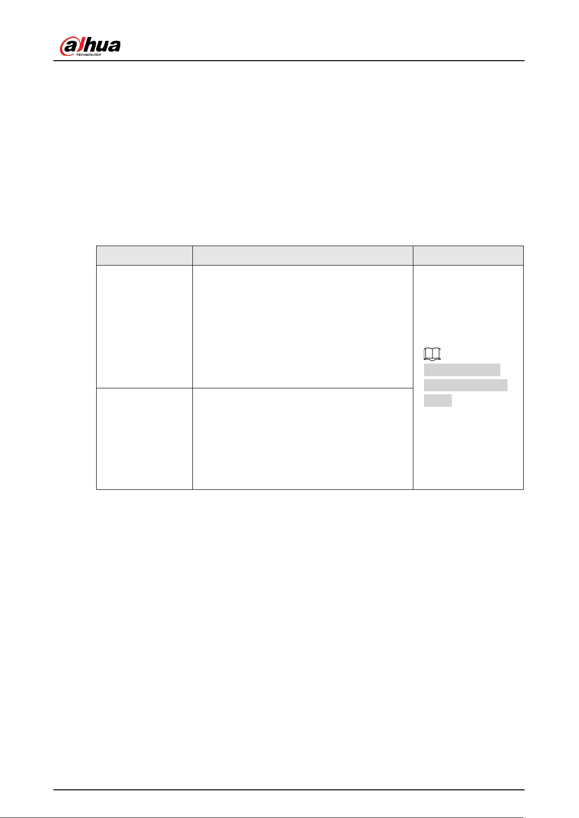
Table 1-1 Barrier type
Type Description Remark
Straight arm barrier
●
Barrier with 3 m (9.84 ft) straight arm with an
opening/closing time of 0.9 s.
●
Barrier with 4 m (13.12 ft) straight arm with
an opening/closing time of 2 s.
●
Barrier with 5 m (16.40 ft) straight arm with
an opening/closing time of 3 s.
●
Barrier with 6 m (19.69 ft) straight arm with
an opening/closing time of 3 s.
Contact technical
support for specific
needs.
Folding arm barrier
●
For barriers with 3 m (9.84 ft) arms, each of
the two sections of the arm is 1.5 m (4.92 ft),
and has an opening/closing speed of 0.9 s.
●
For barriers with 4 m (13.12 ft) arms, the
main arm is 1.5 m (4.92 ft) and the sub arm is
2 m (6.56 ft). It has an opening/closing time
of 2 s.
1.2 Features
●
With its AC variable frequency motor, drive unit and balance spring, the Barrier has highly stable
and reliable operations. Its motor and spring can sustain up to 5 million uses.
●
The sheet metal casing makes it resistant to corrosion for up to 10 years.
●
Designed with a buffer strip on its arm for enhanced safety. The buffer strip is made of
high-molecular-weight polyurethane (PU) which remains soft and not stiff in cold environments.
It has a lifespan for more than 10 years.
●
Automatically rises when the barrier arm makes contact with an object.
●
Barriers with 3 m (9.84 ft) or 4 m (13.12 ft) straight arms support the anti-collision function. A
turning gear is installed between the arm and the main shaft, allowing the arm to swing back
from a collision to avoid mechanical damage.
●
The arm automatically rises at 90° in case of power failure. You can contact technical support to
customize the angle.
●
Anti-drop function activates through its connection with the radar, loop, or IR sensor.
●
12 VDC power adapter that is capable of supplying power to the connected radar.

User's Manual
2
●
Supports remote control at a maximum distance of 50 m (164 ft) with no interference.
User's Manual
3
2 Structure
2.1 Appearance
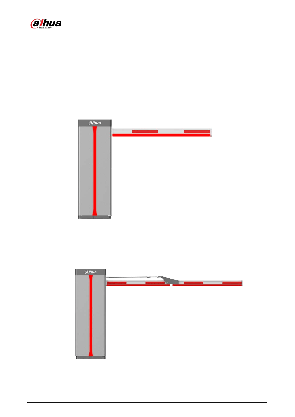
Straight Arm Barrier
Figure 2-1 Straight arm barrier
Folding Arm Barrier
Figure 2-2 Folding arm barrier
User's Manual
4
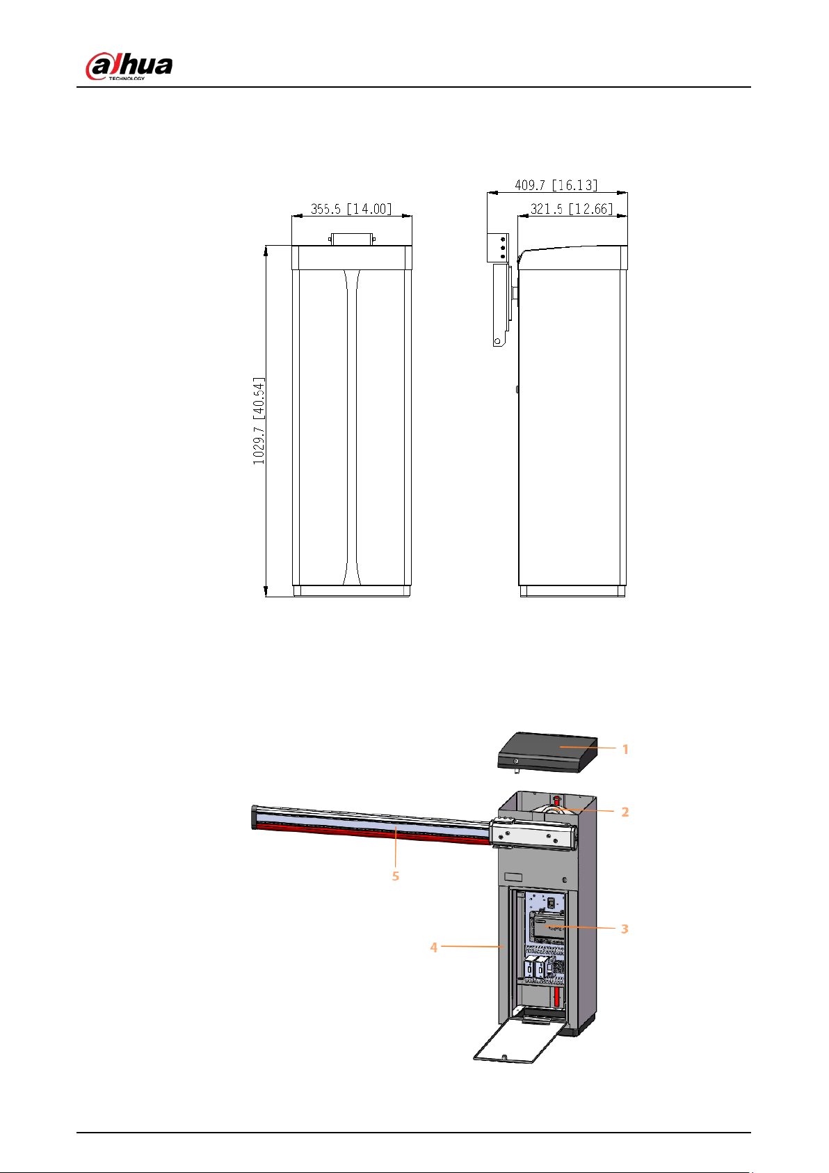
2.2 Dimensions
Figure 2-3 Dimensions (mm [inch])
2.3 Components
Figure 2-4 Components

User's Manual
5
Table 2-1 Components description
No. Name Description
1 Top cover
Fixed to the casing by a lock, which can be unlocked
with a key.
2 Drive unit
Driven by a torque motor, it controls the arm to rise or
fall.
3 Control box
Contains the control board, on which the barrier inverter
and connection terminals are installed.
4 Casing Applied with a plastic spray.
5 Barrier arm
●
Straight arms with light bars.
●
Folding arms.
User's Manual
6
3 Installation
3.1 Installation Preparation
●
This section introduces basic requirements for selecting and constructing the foundation. For
details on installing the Barrier, see the construction guide.
●
The foundation must be constructed before the Barrier is installed.
Selecting Construction Site
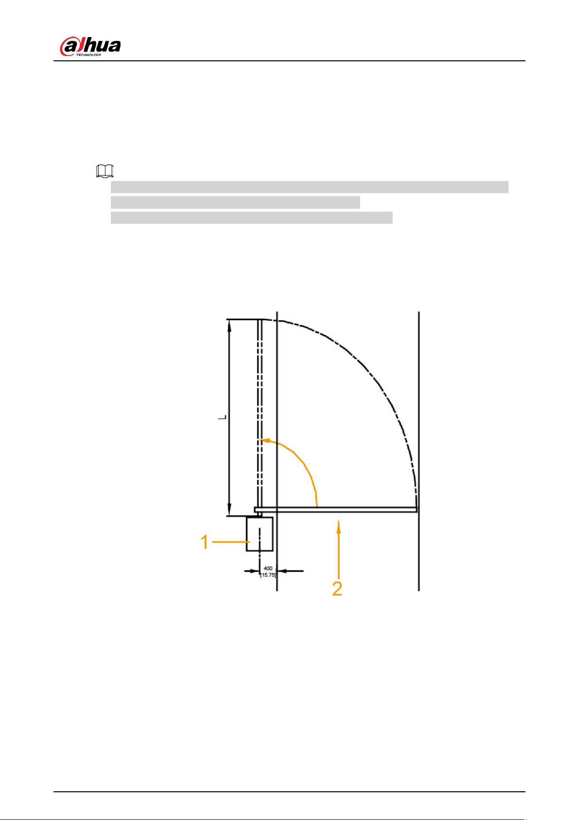
The center of the foundation should be more than 300 mm (11.81'') away from the road side. The
barrier arm can open at a 90° angle vertical to the ground.
Figure 3-1 Installation site of foundation (mm [inch])
●
1: Barrier (installed on the foundation).
●
2: Vehicle movement direction.
User's Manual
7
Foundation Construction Requirements
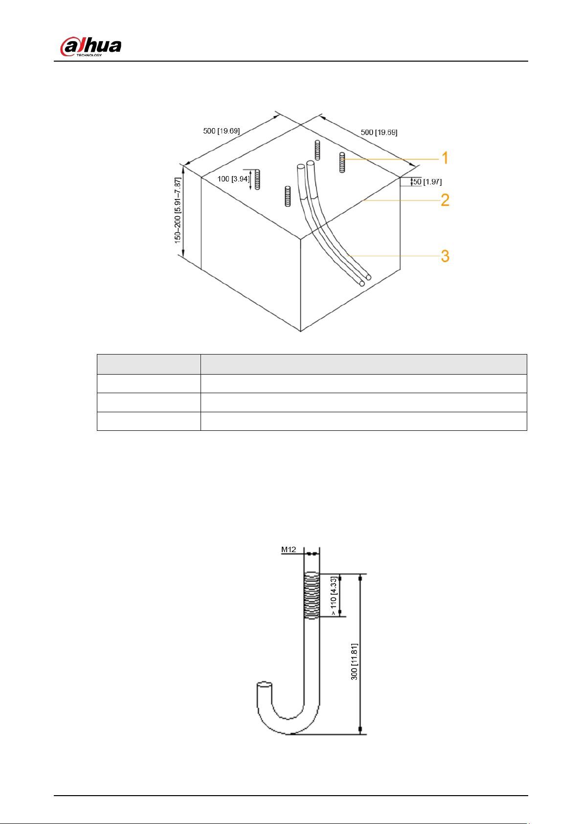
Figure 3-2 Foundation construction requirements (mm [inch])
Table 3-1 Foundation description
No. Name
1 Foundation bolt
2 Foundation surface
3 PVC pipe
●
Pour concrete to construct a foundation of 500 mm× 500 mm (19.69''× 19.69'') (L × W), and make
sure that the depth is between 150 mm–200 mm (5.91''–7.87''). Depths that do not fall within this
range will greatly influence the accuracy of radar detection.
●
Use concrete of at least grade C15.
●
Bury foundation bolts in the foundation. Make sure that the bolts are exposed 100 mm (3.94'')
above the foundation.
Figure 3-3 Foundation bolt (mm [inch])
●
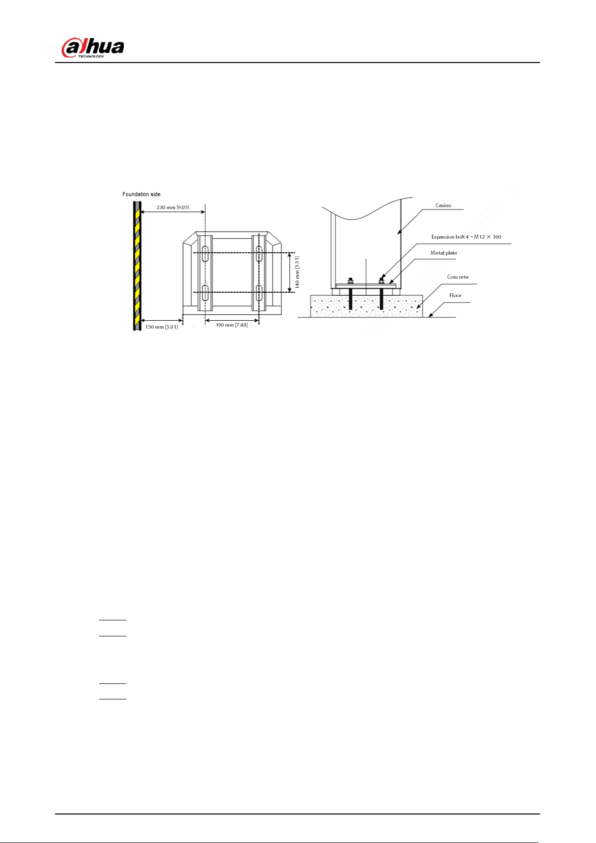
(Optional) If no foundation bolts are buried, you can use the expansion bolts provided in the
accessories of the Barrier.
User's Manual
8
◇
After the concrete foundation hardens, drill 4 holes with a diameter of 16 mm (0.63'') to install
the Barrier.
◇
Use M12 expansion bolts. Make sure that the thread length of the expansion bolt is longer
than 80 mm (3.15''), and its total length is more than 150 mm (5.91'').
◇
The drilled holes and the installation position should meet the requirements shown in Figure
3-4 to facilitate installing the metal plates and fixing the Barrier.
Figure 3-4 Install expansion bolt (top view) (mm [inch])
●
Thread the power cable and the signal cable separately through two 1-inch PVC pipes (buried in
the foundation) to the cable holes next to the foundation.
●
After installation, make sure that when opening the Barrier, there are no obstacles within a 90°
vertical range.
3.2 Installing the Barrier
3.2.1 Installing the Casing
Prerequisites
●
Read the manual carefully before installation. Refer to the barrier drawing attached to the casing
to know how the Barrier works and how to wire it.
●
Check whether the power cable, signal cable, or internal wiring is loose or disconnected. If yes,
securely connect the cables before installation.
Procedure
Step 1 Unpack the packaging box.
Step 2 Place the casing on the foundation, and set the working direction of the arm vertical to the
vehicle movement direction (we recommend placing a layer of 3mm rubber under the
casing to reduce vibrations).
Step 3 Use the key to open the door, and then place metal plates on the foundation bolts.
Step 4 Adjust the horizontal and vertical positions of the casing, and then tighten the nuts with a
wrench.
User's Manual
9
3.2.2 Installing the Folding Arm
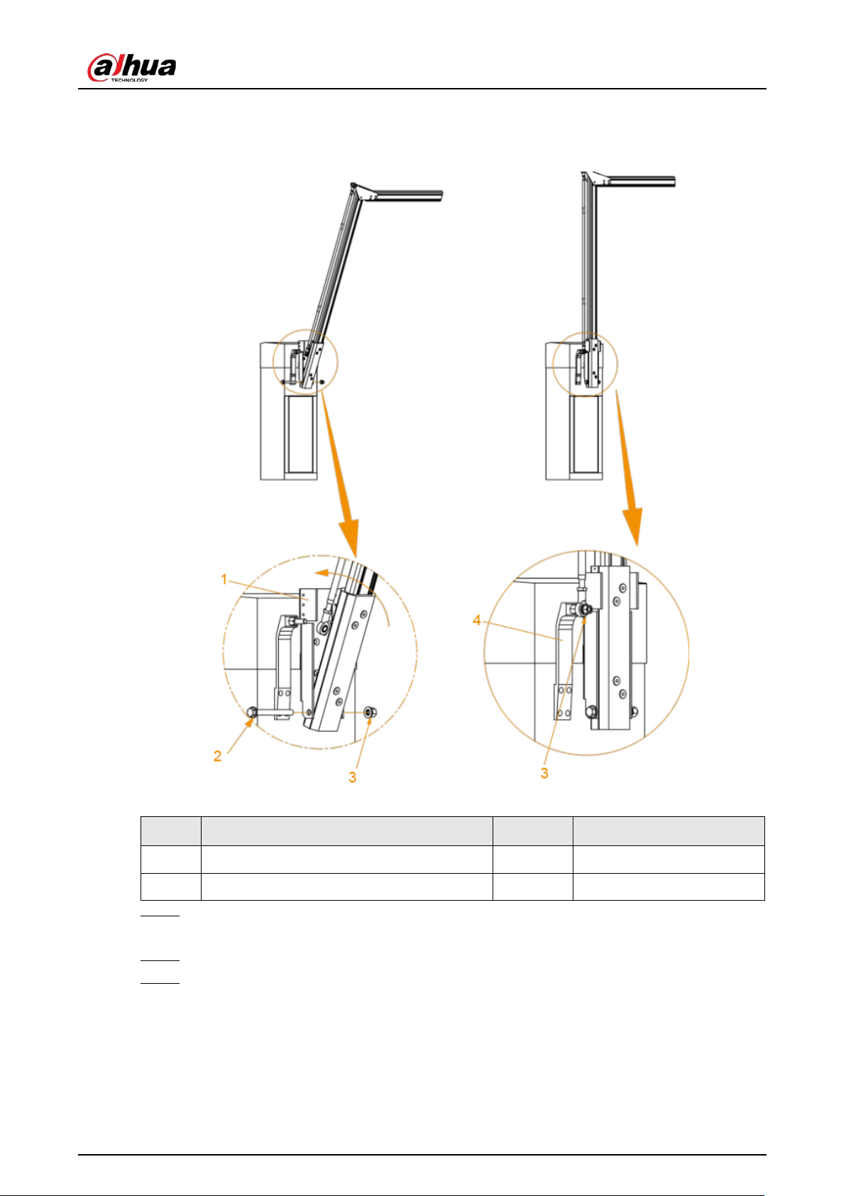
Figure 3-5 Example of a successful installation
Table 3-2 Parts description
No. Description No. Description
1 Mounting plate 3 M14 nut and spring washer
2 M14 × 140 hex head bolt and plain washer 4 Fixing plate
Step 1 Align the arm with the mounting plate, and fix the mounting plate to the arm with M14 ×
140 hex head bolt.
Step 2 Push the arm to make it fit with the mounting plate completely.
Step 3 Install the control arm (right above the barrier arm) and then attach the plate.
3.2.3 Installing the Straight Arm
Different arm lengths require different installation methods.
User's Manual
10
Arms shorter than 4 m (included) are anti-smashing.
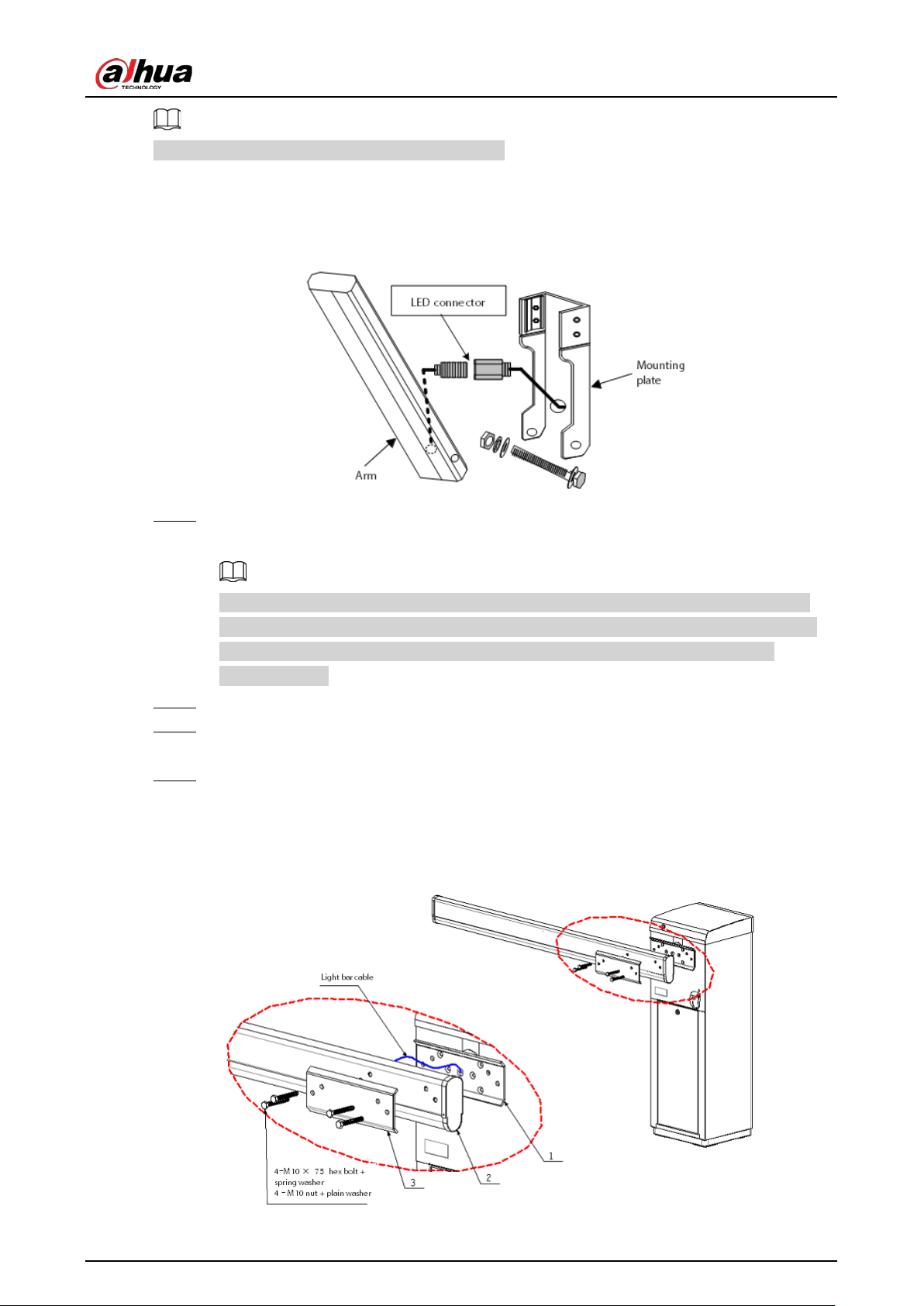
3.2.3.1 Installing the Anti-smashing Arm
Figure 3-6 Install the anti-smashing arm
Step 1 Connect the LED light bar that is fed through the arm to the cable that comes out of the
mounting plate.
The cable coming out of the mounting plate needs to be fixed to the plate surface with
fixing screws, in a way that allows the fixed cable to fit into the cable groove on the arm.
This will ensure the LED connector remains intact when the arm is attached to the
mounting plate.
Step 2 Place the arm in the mounting plate, and align the holes of the arm with those of the plate.
Step 3 Thread the M14 × 140 hex head bolt through the plate and the arm, and fix the bolt with
M14 nut, plain washer and spring washer.
Step 4 Push the arm to make it fit in the mounting plate completely.
3.2.3.2 Installing the Regular Arm
Figure 3-7 Install the regular arm
User's Manual
11
Step 1 Thread four M10 × 75 bolts and plain washers through parts 1, 2, and 3.
Step 2 Fix the bolts with four M10 nuts and spring washers.
3.2.4 Opening the Top Cover
Step 1 Lift the arm up to its vertical state.
Step 2 Use your key to unlock the top cover, wait until the side of the cover near the arm is tilted,
and then push the cover forward to open it.
3.3 Cable Connection
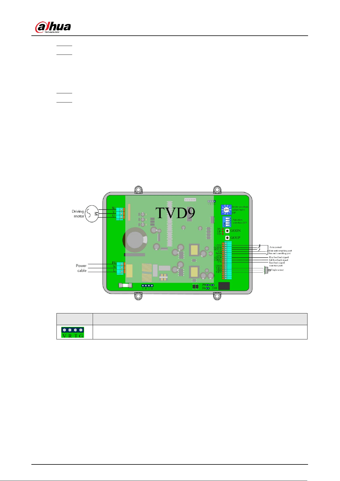
3.3.1 Barrier Inverter Description
Figure 3-8 Barrier inverter
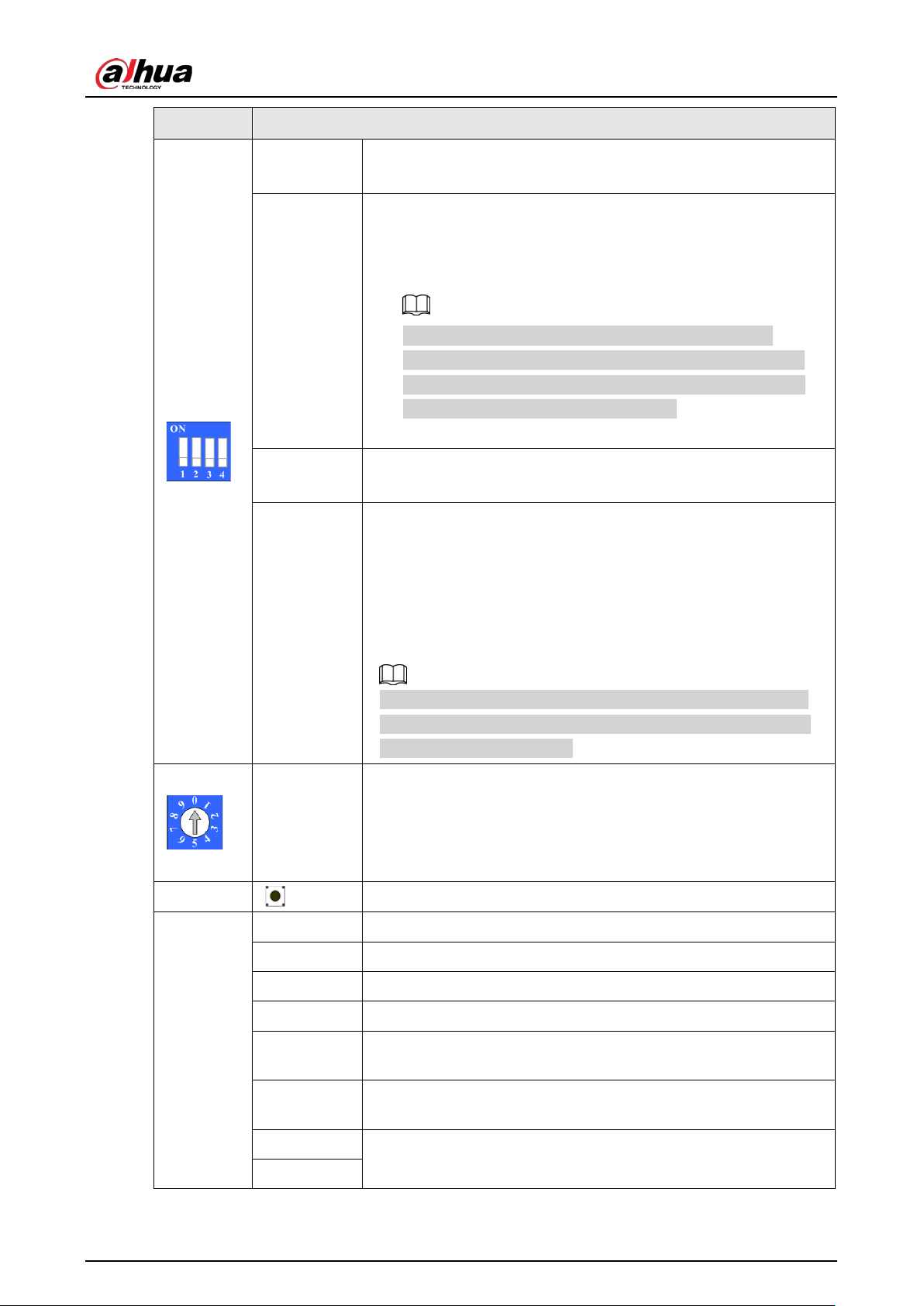
Table 3-3 Barrier inverter description
Parameter Description
Ports for adjusting parameters.
User's Manual
12
Parameter Description
1
●
ON: Enable automatic arm lifting during power failure.
●
OFF: Disable automatic arm lifting during power failure.
2
Counting mode: Under this mode, when the Barrier is powered on,
and there is no anti-smashing signal triggered, the arm
automatically falls.
●
2 and 3 are ON: Enable counting mode.
When the Barrier receives N signals (N ≤ 5) of opening,
including from camera and remote control, the arm will fall
after receiving N signals of vehicle passing, and the interval
between signals is longer than 1 second.
●
OFF: Disable the counting mode.
3
●
ON: Enable the function of auto-falling when vehicle passing.
●
OFF: Disable the function of auto-falling when vehicle passing.
4
●
ON: The
Always on
point of the anti-smashing vehicle
detector output is connected between the inverter VD port
and +24 V port (VD connects to NO and +24 V to COM).
●
OFF: The
Always off
point of the anti-smashing vehicle
detector output is connected between the inverter VD port
and +24 V port (VD connects to NC and +24 V to COM).
When the vehicle detector detects vehicle passing, the inverter
keeps the arm lifted and lifts the arm that is falling, and the arm
falls after the vehicle passed.
Brake
position
adjustment
DIP (0–9)
●
0: Switch the DIP to 0 after adjusting arm stability.
●
1: Invalid position.
●
2–9: Adjust the brake position of the arm during rising or
falling while adjusting arm stability. The larger the number,
the later the arm starts decelerating.
Buttons
Open and close the Barrier.
Ports
–24 V Ground.
COM Feedback signal common port.
LDUP Barrier open feedback signal.
LDDN Barrier close feedback signal.
BOOM
Auxiliary anti-smashing port, which only triggers anti-smashing. It
does not control automatic close of barrier.
VD
Common anti-smashing port. The barrier automatically closes
after the anti-smashing signal disappears.
GOUP
Ports for controlling open and close of the Barrier.
●
GOUP: Open.
GODN
User's Manual
13
Parameter Description
+24V
●
GODN: Close.
●
+24 V: Common signal port.
VRV
Angle sensor ports.
VRG
VRS
PE
Drive motor ports.
U
V
W
L
220 VAC power supply ports for the barrier inverter.
N
PE
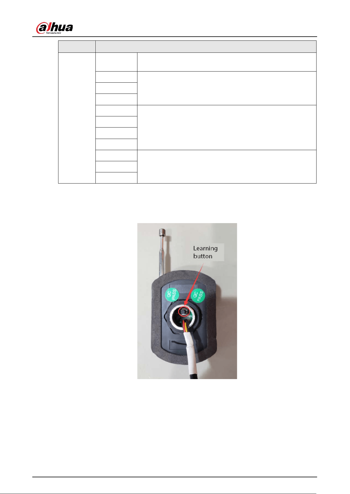
3.3.2 Remote Matching Description
Figure 3-9 Receiver
●
Match the remote information
◇
Successful matching: Press and hold the learning button on the receiver for 2 s, press the
remote handle at least twice and then you can press keys on the remote to control the arm.
◇
Failed matching: The remote handle is not pressed a while after pressing the learning button
on the receiver, and the receiver indicator does not flash 3 times immediately, but flashes 7
times after about 8 seconds.
●
Clear the remote information: Press and hold the learning button on the receiver for more than 3
seconds, and then the remote cannot control the arm. This means the matching information has
User's Manual
14
been cleared.
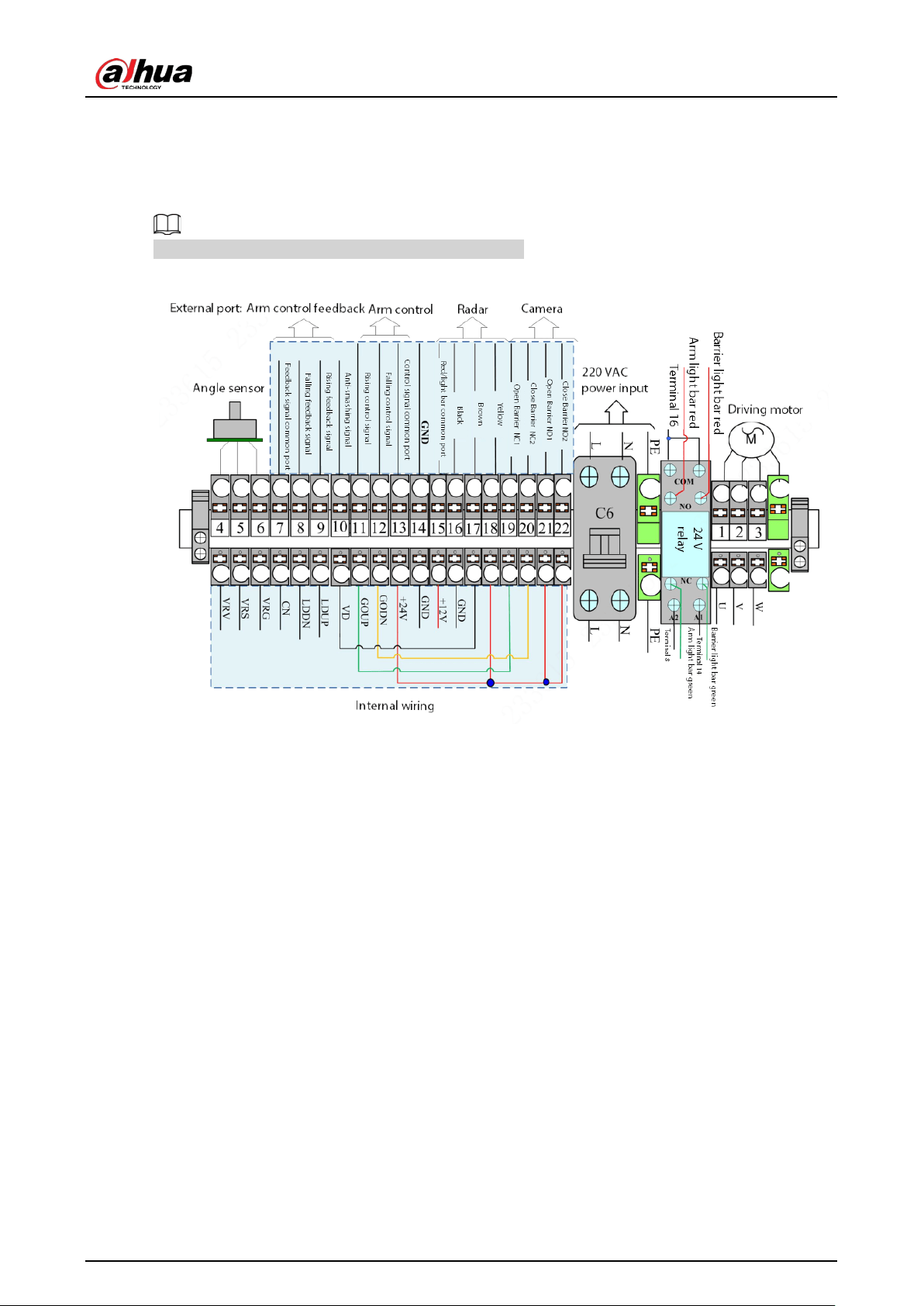
3.3.3 Wiring Instructions
The wiring diagram can be found on the Barrier casing.
Figure 3-10 Wiring diagram
●
Connect to power:
◇
PE: Connect to earth wire.
◇
N: Connect to neutral wire.
◇
L: Connect to live wire.
●
Connect to radar:
◇
Connect the red cable of the radar to port 15 (terminal).
◇
Connect the black cable of the radar to port 16 (terminal).
◇
Connect the brown cable of the radar to port 17 (terminal).
◇
Connect the yellow cable of the radar to port 18 (terminal).
●
Connect to camera:
◇
Open barrier: Connect port 21 (terminal) to NO1 (camera), and connect port 19 (terminal) to
NC1 (camera) through port 4 (terminal).
◇
Close barrier: Generally, you do not need to connect cables for controlling barrier closing
signals. If you want to, connect 22 (terminal) to NO2 (camera), and connect 20 (terminal) to
NC2 (camera).
●
Connect to IR sensor for anti-smashing: Change the GODN port corresponding to port 20
(terminal) to INT port, and NO2, NC2 ports for connecting cameras in the above figure to
anti-smashing terminals of the IR sensor.
●
Connect to vehicle detector for anti-smashing: Connect 10 (terminal) to the NO (normal on point)
of the vehicle detector, and 13 to the common port (NC).

User's Manual
15
4 Maintenance
4.1 Notes on Using the Barrier
●
Avoid bumping during use. If bumping occurs, do the following:
◇
Check whether the slewing mechanism is damaged. If so, replace it in time.
◇
Check whether the barrier arm is bent. If so, replace it in time.
◇
Check whether there is any abnormal sound during operation. If so, contact after-sales
service.
●
We recommend you use standard arms of the Barrier to ensure a long service life.
●
Damages caused by improper operations and non-quality faults are not covered by the warranty.
4.2 Regular Maintenance
Maintain the Barrier every three months.
●
Whether the rubber buffer is normal.
●
Whether the mechanical transmission is smooth.
●
Whether there is abnormal noise during motor operation.
●
Whether the wiring is loose and the ground is reliable.
●
Whether the casing is loose.
4.3 Maintenance Methods
4.3.1 Replacing the Rubber Buffer
The rubber buffer might be worn after long-term use, and should be replaced in time to ensure
smooth operation of the Barrier and the motor. Follow the steps below to replace the buffer:
●
Cut off the power to the Barrier.
●
Open the door, and lower the panel.
●
Remove the top cover.
●
Remove the worn rubber buffer, replace it with a good one, and fix the new buffer.
●
Do not increase or decrease the gasket when replacing the rubber buffer.
●
After replacing the rubber buffer and fixing the top cover, manually lift and lower the arm several
times to make sure that the mechanical movement is flexible and smooth, then you can power
on and operate the Barrier.
4.3.2 Maintaining the Drive Unit
●
Check whether the fastening bolts of the drive unit are loose, and whether the bearing works
User's Manual
16
normally when the Barrier opens or closes.
●
Check whether the transmission part is loose and therefore affecting the running of the Barrier.
●
Check whether there is any abnormal noise during the operation of the motor. If so, contact
after-sales service.
4.3.3 Maintaining the Angle Sensor
The angle sensor is connected to the main shaft to detect the real-time position and speed of the
barrier arm when it is running. Check the angle sensor when the Barrier jitters obviously.
Step 1 Cut off power supply to the Barrier, and remove the three leads of the angle sensor
(labeled 4, 5, 6).
Step 2 Use a multimeter (20 KΩ resistance), and connect the red and black test leads to 4, 5
respectively.
Step 3 Manually make the barrier arm move slowly from the opening status to the closed status.
Step 4 The resistance reading should change between 5 KΩ ± 2% and 7.4 KΩ ± 2%, and the
reading becomes smaller when the arm is raised and larger when the arm falls. In the
changing process of resistance, there is no jumping phenomenon. If anything is abnormal,
adjust the angle sensor to make the resistance fall within the specified range.
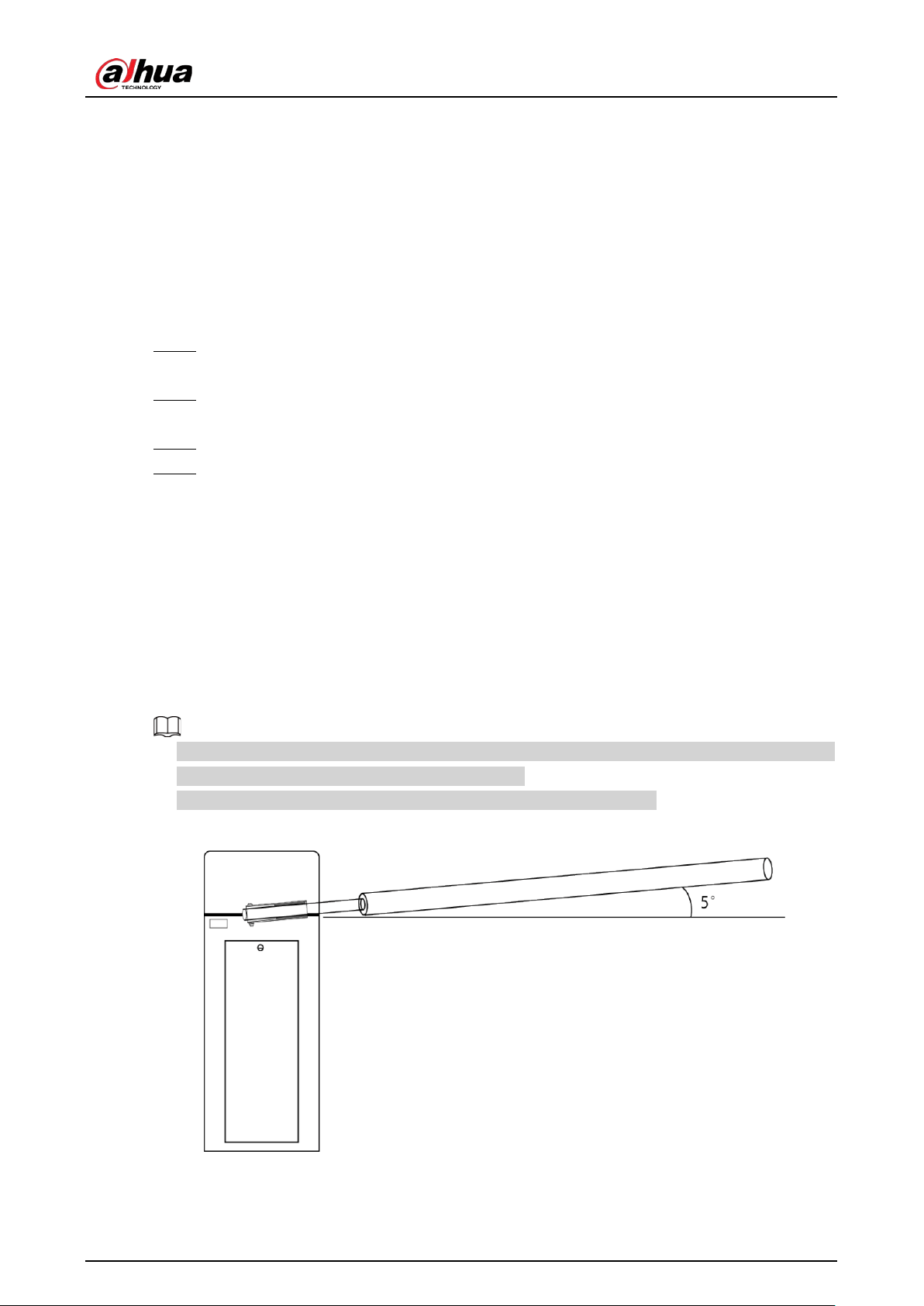
4.3.4 Adjusting the Balance Spring
When changing the barrier arm, you need to adjust the balance spring to fit the new barrier arm.
When the barrier arm is at an angle of about 5° from the horizontal line, release the barrier arm, and
the arm will slowly rise to the vertical position.
●
The balance spring is adjusted according to the model of the Barrier. Do not change the model or
length of the arm without professional instructions.
●
The length of the balance spring might differ depending on the model.
Figure 4-1 Adjust balance spring

User's Manual
17
Table 4-1 Spring matching standard
Arm Type Arm Length (m) Number of Spring
Straight arm with light bar
L ≤ 3.7 1 × 5.2 spring
3.7 < L ≤ 4.5 1 × 6.3 spring
4.5 < L ≤ 5.0 2 × 6.3 spring
5.0 < L ≤ 5.5 1 × 5.2 spring + 2 × 6.3 spring
5.5 < L ≤ 6.0 3 × 6.3 spring
Folding arm
L ≤ 3.4 1 × 5.2 spring
3.4 < L ≤ 4 1 × 6.3 spring
●
The bottom of the 5.2 spring is wrapped with a red threaded protective cover.
●
The bottom of the 6.3 spring is wrapped with a blue threaded protective cover.

User's Manual
18
Appendix 1 Cybersecurity Recommendations
Cybersecurity is more than just a buzzword: it’s something that pertains to every device that is
connected to the internet. IP video surveillance is not immune to cyber risks, but taking basic steps
toward protecting and strengthening networks and networked appliances will make them less
susceptible to attacks. Below are some tips and recommendations from Dahua on how to create a
more secured security system.
Mandatory actions to be taken for basic equipment network security:
1.
Use Strong Passwords
Please refer to the following suggestions to set passwords:
●
The length should not be less than 8 characters.
●
Include at least two types of characters; character types include upper and lower case letters,
numbers and symbols.
●
Do not contain the account name or the account name in reverse order.
●
Do not use continuous characters, such as 123, abc, etc.
●
Do not use overlapped characters, such as 111, aaa, etc.
2.
Update Firmware and Client Software in Time
●
According to the standard procedure in Tech-industry, we recommend to keep your
equipment (such as NVR, DVR, IP camera, etc.) firmware up-to-date to ensure the system is
equipped with the latest security patches and fixes. When the equipment is connected to the
public network, it is recommended to enable the“auto-check for updates” function to obtain
timely information of firmware updates released by the manufacturer.
●
We suggest that you download and use the latest version of client software.
"Nice to have" recommendations to improve your equipment network security:
1.
Physical Protection
We suggest that you perform physical protection to equipment, especially storage devices. For
example, place the equipment in a special computer room and cabinet, and implement
well-done access control permission and key management to prevent unauthorized personnel
from carrying out physical contacts such as damaging hardware, unauthorized connection of
removable equipment (such as USB flash disk, serial port), etc.
2.
Change Passwords Regularly
We suggest that you change passwords regularly to reduce the risk of being guessed or cracked.
3.
Set and Update Passwords Reset Information Timely
The equipment supports password reset function. Please set up related information for password
reset in time, including the end user’s mailbox and password protection questions. If the
information changes, please modify it in time. When setting password protection questions, it is
suggested not to use those that can be easily guessed.
4.
Enable Account Lock
The account lock feature is enabled by default, and we recommend you to keep it on to
guarantee the account security. If an attacker attempts to log in with the wrong password several
times, the corresponding account and the source IP address will be locked.
5.
Change Default HTTP and Other Service Ports
We suggest you to change default HTTP and other service ports into any set of numbers between

User's Manual
19
1024–65535, reducing the risk of outsiders being able to guess which ports you are using.
6.
Enable HTTPS
We suggest you to enable HTTPS, so that you visit Web service through a secure communication
channel.
7.
MAC Address Binding
We recommend you to bind the IP and MAC address of the gateway to the equipment, thus
reducing the risk of ARP spoofing.
8.
Assign Accounts and Privileges Reasonably
According to business and management requirements, reasonably add users and assign a
minimum set of permissions to them.
9.
Disable Unnecessary Services and Choose Secure Modes
If not needed, it is recommended to turn off some services such as SNMP, SMTP, UPnP, etc., to
reduce risks.
If necessary, it is highly recommended that you use safe modes, including but not limited to the
following services:
●
SNMP: Choose SNMP v3, and set up strong encryption passwords and authentication
passwords.
●
SMTP: Choose TLS to access mailbox server.
●
FTP: Choose SFTP, and set up strong passwords.
●
AP hotspot: Choose WPA2-PSK encryption mode, and set up strong passwords.
10.
Audio and Video Encrypted Transmission
If your audio and video data contents are very important or sensitive, we recommend that you
use encrypted transmission function, to reduce the risk of audio and video data being stolen
during transmission.
Reminder: encrypted transmission will cause some loss in transmission efficiency.
11.
Secure Auditing
●
Check online users: we suggest that you check online users regularly to see if the device is
logged in without authorization.
●
Check equipment log: By viewing the logs, you can know the IP addresses that were used to
log in to your devices and their key operations.
12.
Network Log
Due to the limited storage capacity of the equipment, the stored log is limited. If you need to
save the log for a long time, it is recommended that you enable the network log function to
ensure that the critical logs are synchronized to the network log server for tracing.
13.
Construct a Safe Network Environment
In order to better ensure the safety of equipment and reduce potential cyber risks, we
recommend:
●
Disable the port mapping function of the router to avoid direct access to the intranet devices
from external network.
●
The network should be partitioned and isolated according to the actual network needs. If
there are no communication requirements between two sub networks, it is suggested to use
VLAN, network GAP and other technologies to partition the network, so as to achieve the
network isolation effect.
●
Establish the 802.1x access authentication system to reduce the risk of unauthorized access to
private networks.

User's Manual
20
●
Enable IP/MAC address filtering function to limit the range of hosts allowed to access the
device.
More information
Please visit Dahua official website security emergency response center for security announcements
and the latest security recommendations.

User's Manual