
I
Boom Gate (DHI-IPMECD-105X Series)
User’s Manual
V1.0.0
ZHEJIANG DAHUA VISION TECHNOLOGY CO., LTD.
User’s Manual
I
Foreword
This manual introduces the installation, functions and operations of the boom gate. Read carefully
before using the device, and keep the manual safe for future reference.
Models
Series Model
DHI-IPMECD-1051 Series
DHI-IPMECD-1051-LM1515-T28
DHI-IPMECD-1051-LM1525-T30
DHI-IPMECD-1051-LM2525-T50
DHI-IPMECD-1051-RM1515-T28
DHI-IPMECD-1051-RM1525-T30
DHI-IPMECD-1051-RM2525-T50
DHI-IPMECD-1052 Series
DHI-IPMECD-1052-LM30-T15
DHI-IPMECD-1052-LM3040-T28
DHI-IPMECD-1052-LM4050-T48
DHI-IPMECD-1052-LM5060-T55
DHI-IPMECD-1052-RM30-T15
DHI-IPMECD-1052-RM3040-T28
DHI-IPMECD-1052-RM4050-T48
DHI-IPMECD-1052-RM5060-T55
DHI-IPMECD-1053 Series
DHI-IPMECD-1053-LM30-T35
DHI-IPMECD-1053-LM35-T42
DHI-IPMECD-1053-LM40-T55
DHI-IPMECD-1053-LM45-T60
DHI-IPMECD-1053-RM30-T35
DHI-IPMECD-1053-RM35-T42
DHI-IPMECD-1053-RM40-T55
DHI-IPMECD-1053-RM45-T60
Safety Instructions
The following signal words might appear in the manual.
Signal Words Meaning
DANGER
Indicates a high potential hazard which, if not avoided, will result in death
or serious injury.
WARNING
Indicates a medium or low potential hazard which, if not avoided, could
result in slight or moderate injury.
CAUTION
Indicates a potential risk which, if not avoided, could result in property
damage, data loss, reductions in performance, or unpredictable results.

User’s Manual
II
Signal Words Meaning
TIPS
Provides methods to help you solve a problem or save time.
NOTE
Provides additional information as a supplement to the text.
Revision History
Version Revision Content Release Time
V1.0.0 First release. April 2023
About the Manual
The manual is for reference only. Slight differences might be found between the manual and the
product.
We are not liable for losses incurred due to operating the product in ways that are not in
compliance with the manual.
The manual will be updated according to the latest laws and regulations of related jurisdictions.
For detailed information, see the paper user’s manual, use our CD-ROM, scan the QR code or
visit our official website. The manual is for reference only. Slight differences might be found
between the electronic version and the paper version.

User’s Manual
III
Important Safeguards and Warnings
This section introduces content covering the proper handling of the boom gate, hazard prevention,
and prevention of property damage. Read carefully before using the device, and comply with the
guidelines when using it.
Transportation Requirements
Pack the boom gate with packaging materials provided by its manufacturer or materials with
the same quality before transporting it.
Transport the boom gate under allowed humidity and temperature conditions.
Storage Requirements
Store the boom gate under allowed humidity and temperature conditions.
Operation Requirements
Make sure that the power supply is correct before running the boom gate.
Do not unplug the power cord on the side of the boom gate when the adapter is powered on.
Operate the boom gate within the rated range of power input and output.
Use the boom gate under allowed humidity and temperature conditions.
Do not drip or splash liquid onto the boom gate, and make sure that there is no object filled
with liquid on the boom gate to prevent liquid from flowing into it.
Do not disassemble the boom gate.
Clean the surface of the boom gate with a soft dry cloth or a clean soft cloth moistened with
neutral detergent.
Do not squeeze, vibrate, or immerse the boom gate in liquid.
We recommend you use the boom gate with a lightning protection device for stronger
protection against lightning. For outdoor scenarios, strictly comply with the lightning
protection regulations.
Ground the function earthing portion of the boom gate to improve its reliability. Make sure that
the power supply of the class I electrical appliance is connected to a power socket with
protective earthing.

User’s Manual
IV
Installation Requirements
WARNING
Do not connect the boom gate to the power adapter when the adapter is powered on.
Strictly comply with the local electrical safety codes and standards. Make sure that the ambient
voltage is stable and meets the power supply requirements.
Do not connect the boom gate to 2 or more kinds of power supplies, to avoid safety risks and
damage to the boom gate.
Use accessories suggested by the manufacturer, and install and maintain the boom gate by
professionals.
When using a laser beam device, avoid exposing the surface of the boom gate to laser beam
radiation.
Personnel working at heights must take all necessary measures to ensure personal safety
including wearing a helmet and safety belts.
Do not install or place the boom gate in a location that exposes it to sunlight or heat sources.
Keep the boom gate away from dampness, dust or soot.
Install the boom gate in well-ventilated places, and do not block its vent.
Use an adapter or cabinet power supply from the manufacturer.
Make sure that the power supply meets the SELV (Safety Extra Low Voltage) requirements and
rated voltage conforms to the GB8898 (IEC60065) or GB4943.1 standard (IEC60950-1 or
IEC62368-1 complies with Limited Power Source). The requirements of the power supply are
subject to the device labels.

User’s Manual
V
Table of Contents
Foreword ............................................................................................................................................................ I
Important Safeguards and Warnings ............................................................................................................. III
1 Product Overview .......................................................................................................................................... 1
Product Introduction ................................................................................................................................................................ 1 1.1
Main Features .............................................................................................................................................................................. 1 1.2
2 Product Structure .......................................................................................................................................... 2
Appearance .................................................................................................................................................................................. 2 2.1
Structure ........................................................................................................................................................................................ 3 2.2
Casing Dimensions .................................................................................................................................................................... 4 2.3
Product Dimensions .................................................................................................................................................................. 4 2.4
Direction ........................................................................................................................................................................................ 7 2.5
3 Product Installation ....................................................................................................................................... 8
Concrete Base Requirements................................................................................................................................................. 8 3.1
Installing the Casing.................................................................................................................................................................. 8 3.2
Installing the Boom ................................................................................................................................................................... 9 3.3
3.3.1 Straight Boom Gate ...................................................................................................................................................... 9
3.3.2 Telescopic Boom Gate ............................................................................................................................................... 10
3.3.3 Folding Boom Gate .................................................................................................................................................... 10
3.3.4 Fence Boom Gate ........................................................................................................................................................ 11
Connecting Cables .................................................................................................................................................................. 12 3.4
3.4.1 Connecting Controller Ports ................................................................................................................................... 13
3.4.2 Configuring Controller Parameters ...................................................................................................................... 15
Adjusting Spring Balance ...................................................................................................................................................... 24 3.5
Remote Control ......................................................................................................................................................................... 26 3.6
4 Maintenance ................................................................................................................................................ 28
FAQ .............................................................................................................................................. 29
Appendix 1
Cybersecurity Recommendations ............................................................................................. 31 Appendix 2

User’s Manual
1
1 Product Overview
Product Introduction 1.1
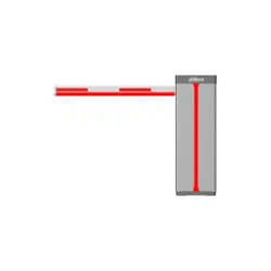
The boom gate consists of a top cover, casing, transmission mechanism, control box, and boom. It
can be controlled on the left or right side, and is ideal for access control at parking lots.
4 types of boom gates are available: the straight, telescopic, folding and fence boom gate.
Main Features 1.2
Uses a 24 VDC brushless servo motor to reduce power consumption, and allow the device to be
safe and perform stably with little noise.
The raising speed of the boom can be adjusted.
The position of the limit switch can be adjusted.
Connects to the camera through RS-485.
You can view the working status of the boom gate on the webpage of the camera, including
running times, operating status, and logs.
Connects to the radar, coil, or IR sensor for anti-smashing. It also has a 12 VDC power supply that
outputs power to radars that are connected.
During the closing process, the boom reverses automatically if it is obstructed.
During a power failure, you can control the servo handle by manually opening and closing the
boom gate.
Uses learning code wireless remote control, convenient and highly-confidential.
Turns on fleet mode with one click, allowing the boom gate to stay open until a specified
amount of vehicles pass.
Counts the number of times the boom gate opens and closes.
The delay time and speed at which the boom gate closes can be set.
Motor lifespan: 3 million times.
Spring lifespan: 800,000–1,000,000 times. The lifespan might vary, depending on the type and
the length of the boom.
User’s Manual
2
2 Product Structure
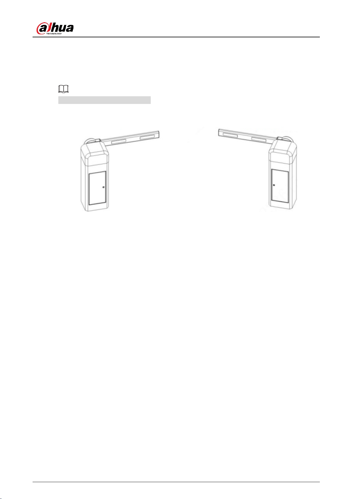
Appearance 2.1
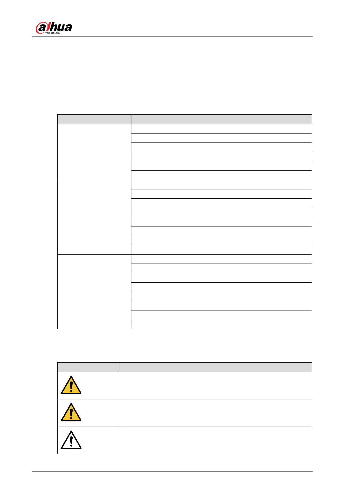
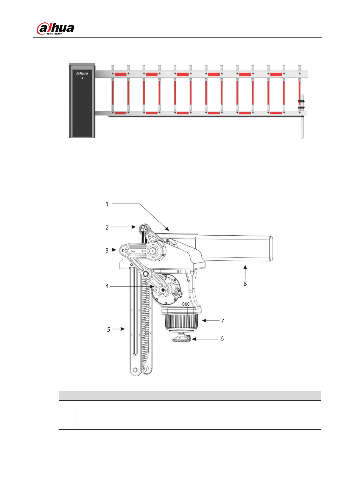
Straight boom gate Figure 2-1
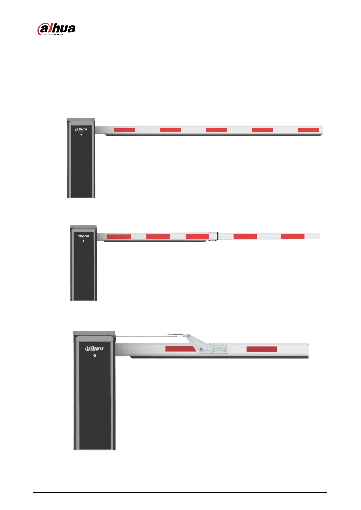
Telescopic boom gate Figure 2-2
Folding boom gate Figure 2-3
User’s Manual
3
Fence boom gate Figure 2-4
Structure 2.2
Structure Figure 2-5
Table 2-1 Structure description
No. Description No. Description
1 Boom handle 5 Balance spring
2 Spring adjustment screw 6 Motor hand wheel
3 Spring lock nut 7 DC brushless servo motor
4 Crank arm 8 Boom
User’s Manual
4
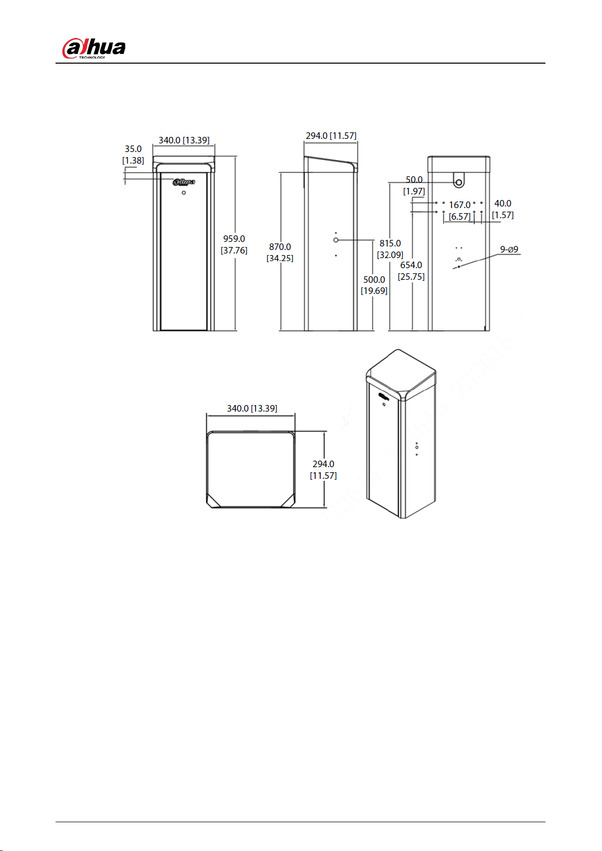
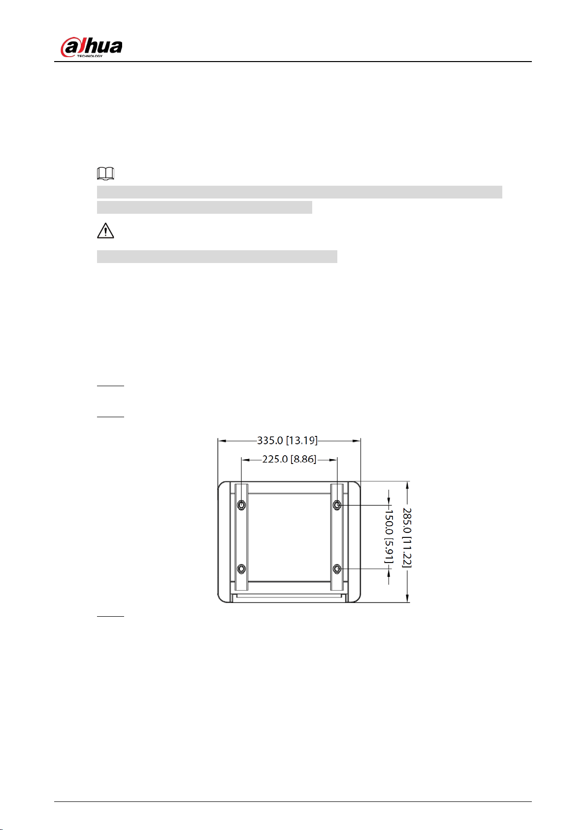
Casing Dimensions 2.3
Casing dimensions (mm [inch]) Figure 2-6
Product Dimensions 2.4
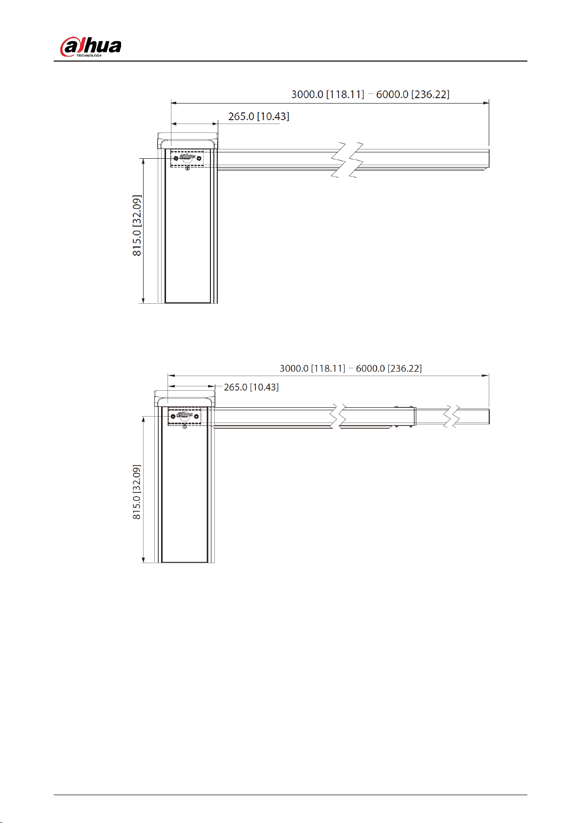
Straight boom gate (opens on the right, and the boom gate is installed on the left side of the
roadway)
User’s Manual
5
Straight boom gate dimensions (mm [inch]) Figure 2-7
Telescopic boom gate (opens on the right, and the boom gate is installed on the left side of the
roadway)
Telescopic boom gate dimensions (mm [inch]) Figure 2-8
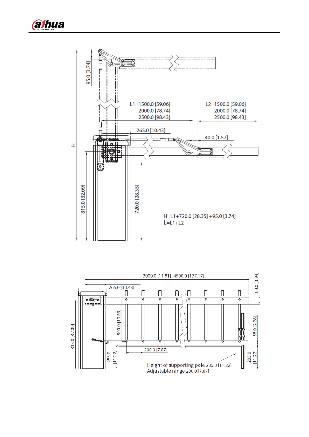
Folding boom gate (opens on the right, and the boom gate is installed on the left side of the
roadway)
User’s Manual
6
Folding boom gate dimensions (mm [inch]) Figure 2-9
Fence boom gate (opens on the right, and the boom gate is installed on the left side of the
roadway)
Fence boom gate dimensions (mm [inch]) Figure 2-10
User’s Manual
7
Direction 2.5
You can recognize the direction of the boom gate by facing the door of its casing. Its direction is the
side that the boom closes on.
The diagrams are for reference only.
Direction Figure 2-11
Opens on the right Opens on the left
User’s Manual
8
3 Product Installation
Concrete Base Requirements 3.1
This section introduces the requirements for selecting and constructing the concrete base. For
details, see the corresponding construction guide.
A concrete base is required for installing the boom gate.
Pour concrete mixer into the location demarked for the base, to construct a concrete base that is
between 150–250 mm above the ground. Heights that do not fall within this range might influence
the accuracy of radar detection.
Installing the Casing 3.2
Place the casing in the set position. Open the door of the casing, use a screwdriver to draw Step 1
lines on the ground along the groove of the base plate, and then move the casing away.
Mark 4 expansion bolt holes according to the dimensions as shown in the following figure. Step 2
Casing dimensions (mm [inch]) Figure 3-1
Drill holes for the expansion bolts and screw the expansion bolts into the holes. Adjust the Step 3
horizontal and vertical angles of the casing, and then tighten the nuts.
User’s Manual
9
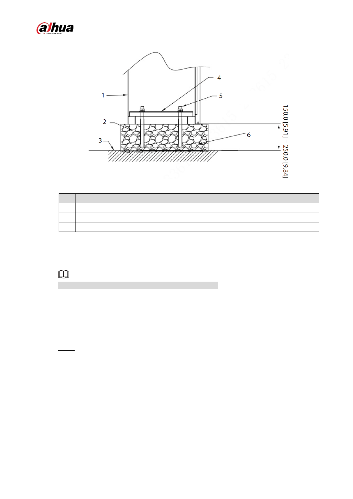
Install the casing (mm [inch]) Figure 3-2
Table 3-1 Description
No. Description No. Description
1 Casing 4 Plate
2 Concrete 5 Expansion screw (4-M12 × 160)
3 Ground 6 Concrete base
Installing the Boom 3.3
The installation diagrams in this section are for reference only.
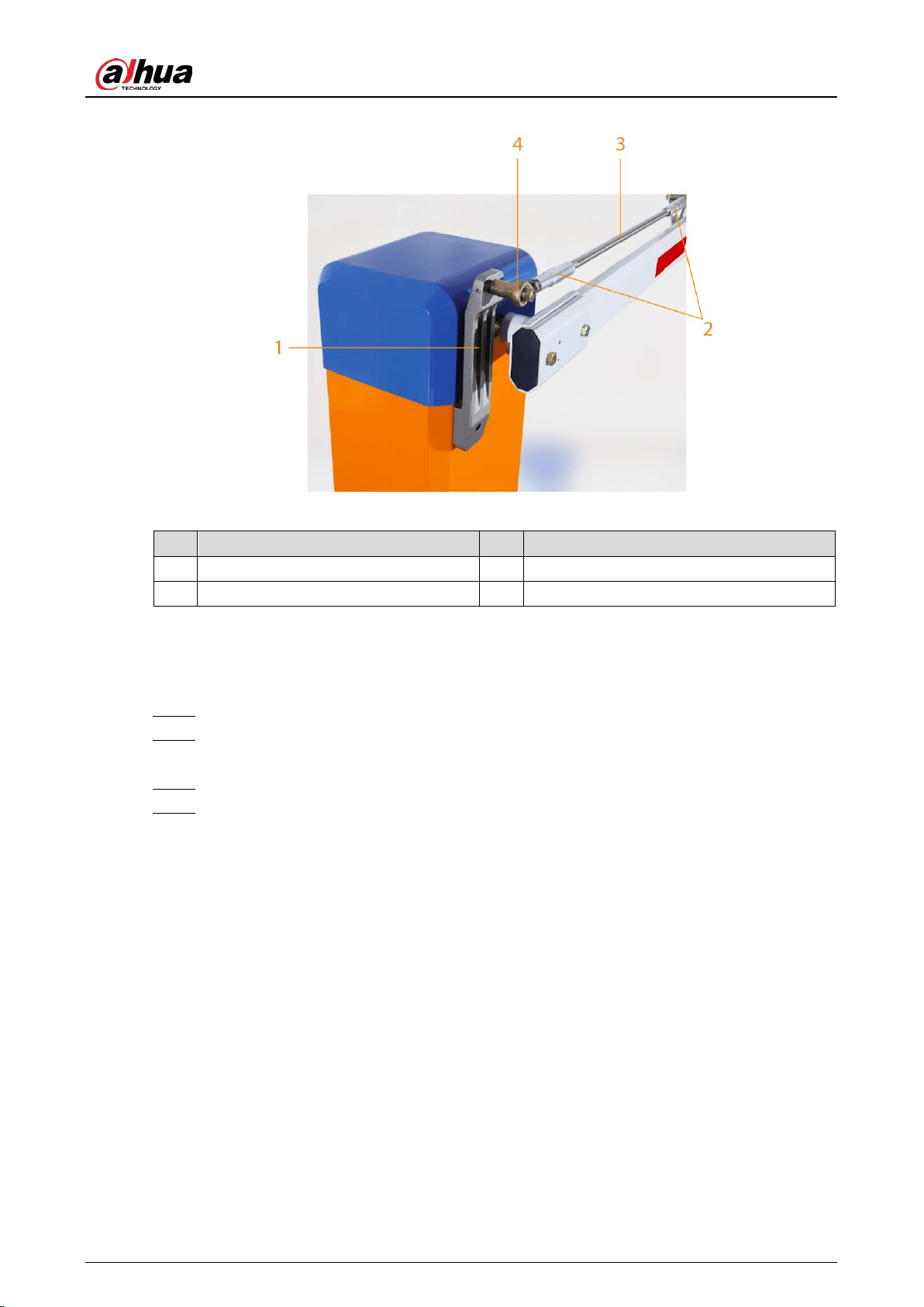
3.3.1 Straight Boom Gate
Use 2 M12 × 70 mm outer hexagon screws to secure the plate of the boom handle to the Step 1
boom.
Hold the plate with your hand, raise the boom vertically, and then fix the plate to the handle Step 2
connector.
Install the flat washer, spring washer, and M12 nut on the screws, and then use a wrench to Step 3
secure the boom screws.
User’s Manual
10
Install the straight boom gate Figure 3-3
Table 3-2 Straight boom gate description
No. Description No. Description
1 M12 × 70 outer hexagon screw 3 Handle connector
2 Plate for boom handle — —
3.3.2 Telescopic Boom Gate
The procedure for installing a telescopic boom gate is the same as that of installing the straight
boom gate. For details, see "3.3.1 Straight Boom Gate".
3.3.3 Folding Boom Gate
Follow Step 1–Step 3 in "3.3.1 Straight Boom Gate". Step 1
Install the bearing on the support plate, and then secure the bearing with screws. Step 2
Loosen the 2 ends of the cast aluminum casing, rotate the stainless steel tube, and adjust Step 3
the horizontal and vertical directions of the boom respectively. After it has been adjusted,
tighten the 2 ends of the cast aluminum casing.
User’s Manual
11
Install the folding boom gate Figure 3-4
Table 3-3 Folding boom gate description
No. Description No. Description
1 Support plate 3 Stainless steel tube
2 Cast aluminum casing 4 Bearing
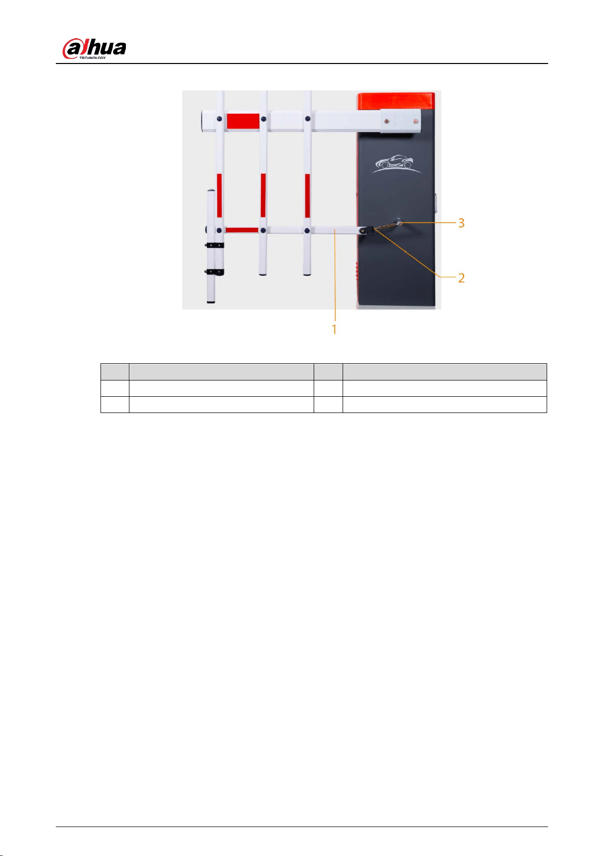
3.3.4 Fence Boom Gate
Follow Step 1–Step 3 in "3.3.1 Straight Boom Gate". Step 1
Use the hex socket to fix one end of the bearing of the U-shaped connector to the cone Step 2
shaft of the casing.
Use screws to secure the lower horizontal bar to the U-shaped connector. Step 3
Loosen the 2 nuts of the U-shaped connector, and then adjust the length of the boom, to Step 4
make it perpendicular to the ground.
User’s Manual
12
Install the fence boom gate Figure 3-5
Table 3-4 Fence boom gate description
No. Description No. Description
1 Lower horizontal bar 3 Cone shaft
2 U-shaped connector — —
Connecting Cables 3.4
The wiring for the boom gate was completed before delivery. Simply connect the boom gate to the
power supply and protective earth wire for it to begin working.
User’s Manual
13
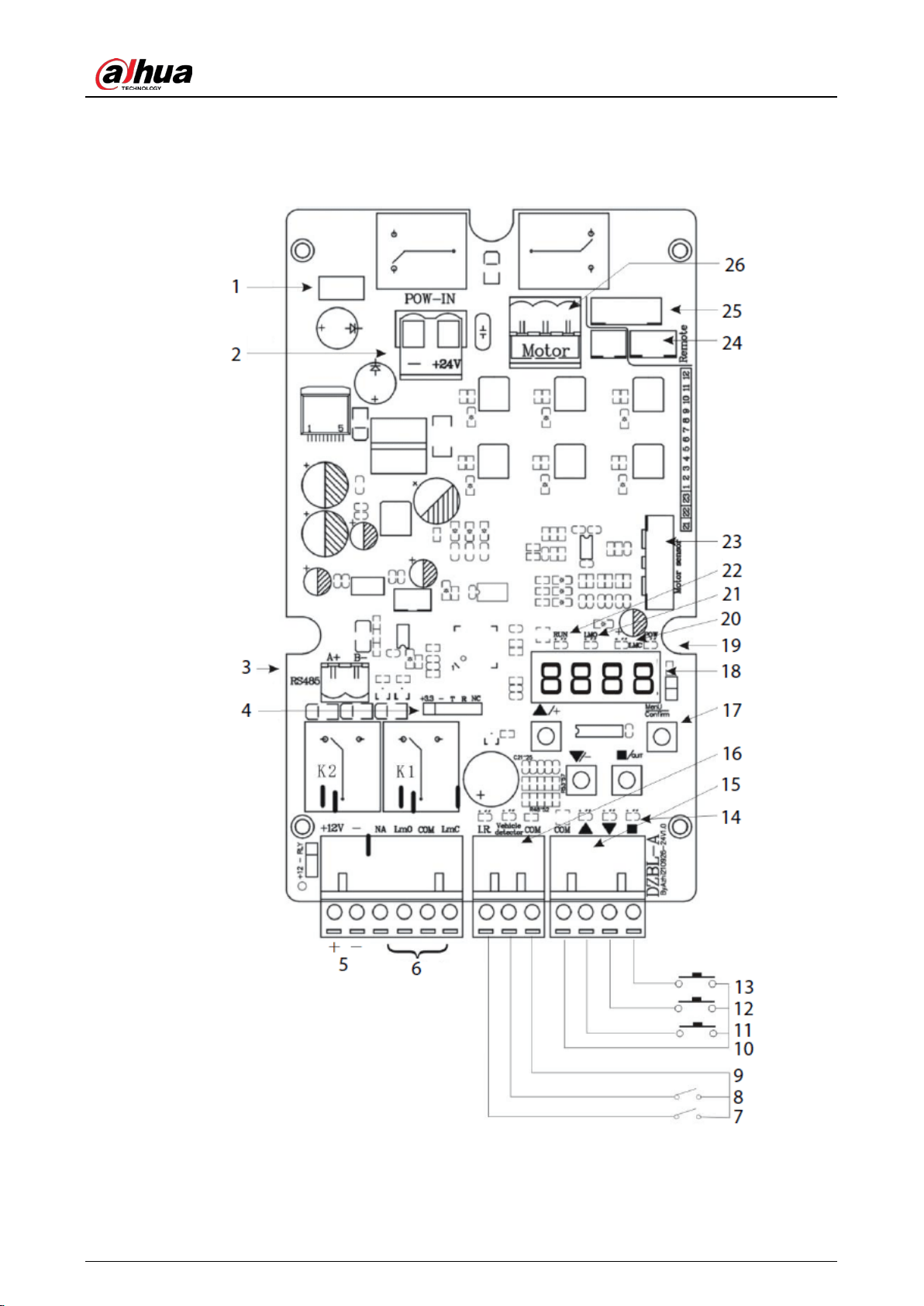
3.4.1 Connecting Controller Ports
Wiring diagram of the controller Figure 3-6
User’s Manual
14
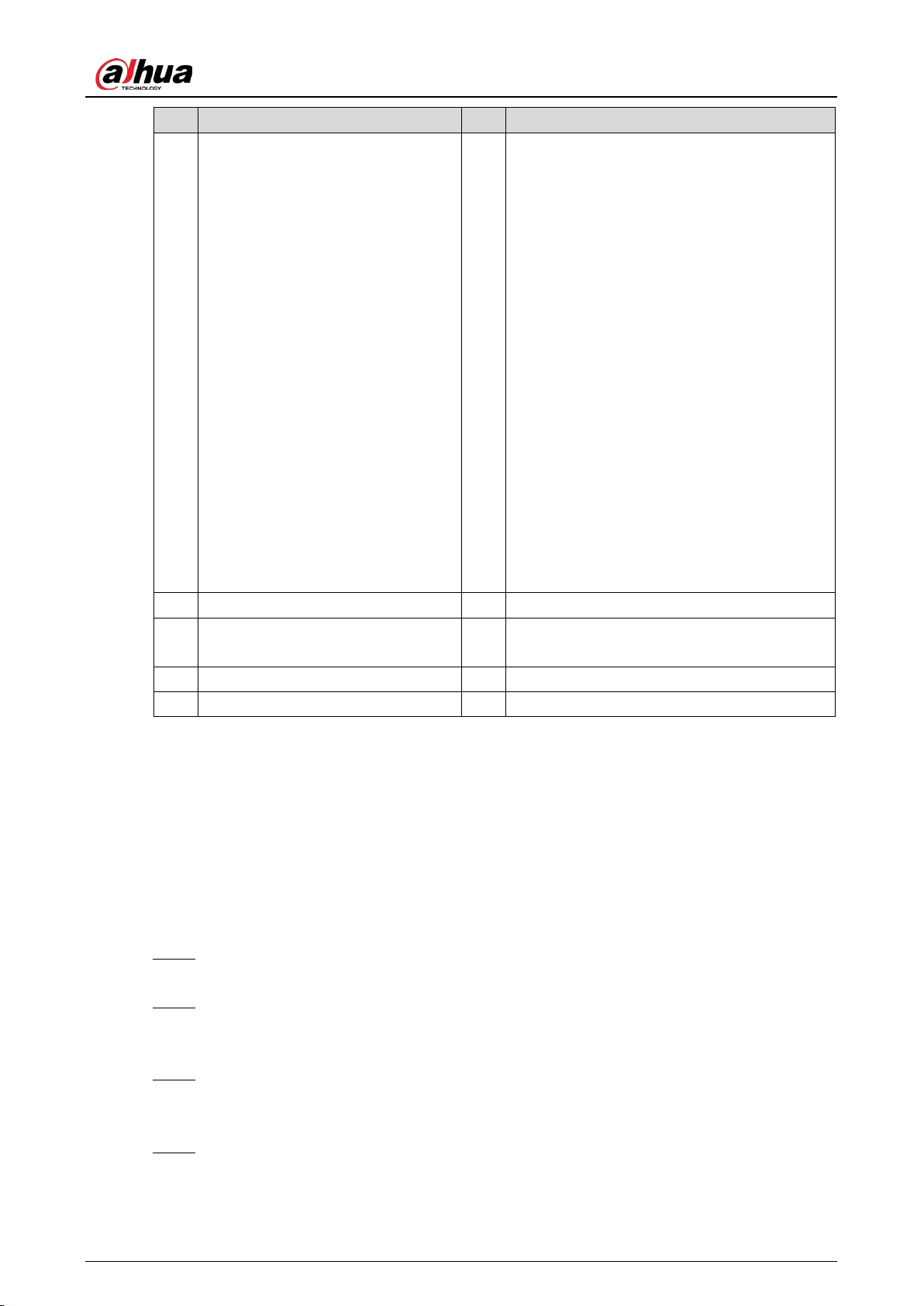
Table 3-5 Controller port description
No. Description No. Description
1 Fuse. 2 24 VDC power input.
3
RS-
485 communication interface.
Connects to the RS-485 port of the
access control camera through a
twisted pair cable, so that the
camera can obtain the working
status, fault code and log of the
boom gate.
4 Bluetooth mode interface (optional).
5
12 VDC power input.
Outputs a maximum of 12 VDC and
1 A current, to supply power to the
radar or IR anti-smashing device.
6 Multiplying relay output interface.
7 IR photocell signal input. 8 Loop detecton and radar signal input.
9 GND (COM). 10 GND (COM).
11 Open. 12 Close.
13 Stop. 14 Wire control indicator.
15
Wire control interface.
Used to
connect the boom gate to the
parking system, or to connect the
external button switches to control
the boom gate.
Open the boom gate: Short
Open and GND.
Close the boom gate: Short
Close and GND.
Stop the boom gate: Short
Stop and GND.
16
Anti-smashing interface.
Anti-smashing by IR sensor: Used when
closing the boom gate, short IR and GND
to open the boom gate.
Anti-smashing by coil:
Used when
closing the boom gate, short coil or radar
and GND to open the boom gate. After
the boom gate is opened,
it will
automatically close when the coil or
radar and GND are disconnected.
User’s Manual
15
No. Description No. Description
17
Function buttons.
The 4 function
buttons have 2 working statuses:
the
normal working status and
menu setting status.
In the
normal working status,
you can press Open, Close, or
Stop to open, close, or stop the
boom gate, and press and hold
Settings for 2 seconds to enter
the menu setting status.
In the menu setting status, you
can press the Open and Close
buttons to adjust the menu
items or parameters, and press
Exit
to cancel settings or exit
the menu setting status. You
can press Settings
to enter
menu of next level, or save the
configurations.
18
Digital tube display. Disp
lays the working
status, parameters, menu items, and other
information of the boom gate.
LED is lit after the boom gate is powered on. If
the buttons are not used within 60 seconds,
the LED will enter low-power mode. In this
mode, the LED dims, and power consumption
is reduced. Press any button for the LED to
enter the normal working status. It will light
up.
19 Power indicator. 20 Close limit indicator.
21 Open limit indicator. 22
Running status indicator.
Indicates the
working status of the boom gate.
23 Motor sensor interface. 24 3-wire radio receiver interface.
25 5-wire radio receiver interface. 26 Motor interface.
3.4.2 Configuring Controller Parameters
3.4.2.1 Common Menu
Common Menu Settings
Press and hold Menu/OK for 2 seconds to enter the menu setting status. Step 1
The LED displays "F-XX".
Select menu items using the Open and Close buttons. Press the button once to select the Step 2
previous or next menu. Press and hold the button to select the previous menu or to
continuously cycle through menus.
When the "F-XX" item displayed is the parameter that you want to set, press Settings to Step 3
start configuring the parameter, and then press Stop to return to the previous level of the
menu or exit the page.
After the parameters have been set, press Settings to save the configurations. If you press Step 4
Stop, the configurations will not be saved. The buzzer on the control panel beeps, the
system exits the menu setting status and returns to the normal working status.

User’s Manual
16
Table 3-6 Common menu list
Menu Function Default Range Description
F-00 Opening speed 50 15–100
The higher the value, the faster the boom gate
opens.
F-01 Closing speed 50 15–100
The higher the value, the faster the boom gate
closes.
F-02
Opening
deceleration angle
50 10–80
The angle that the boom gate starts
decelerating when it is opening.
F-03
Closing
deceleration angle
30 10–80
The angle that the boom gate starts
decelerating when it is closing.
F-04
Low-speed
opening angle
90 45–90
The angle that the boom gate starts opening
when the speed is slow.
F-05
Low-speed closing
angle
0 0–45
The angle that the boom gate starts closing
when the speed is slow.
F-06
Opening end
speed
8 1–50
The speed that the boom gate finishes
opening.
F-07 Closing end speed 4 1–50 The speed that the boom gate finishes closing.
F-08
Horizontal position
adjustment
15 1–255 Fine-tune the horizontal position of the boom.
F-09
Vertical position
adjustment
6 1–99 Fine-tune the vertical position of the boom.
F-10
Automatic delay
closing time
0 0–255
The time that the boom gate automatically
closes if no vehicle passes. Unit: seconds.
F-13
Self-learning speed
after power-on
25 10–80
Learns the up and down limits according the
defined speed.
F-15 Sensitivity of boom 10 1–40
The sensitivity of the boom when it is
obstructed while closing. Unit: 0.05 seconds.
For example, if you set the value to 20, the
sensitivity will be 1 second (0.05 × 20).
Common Menu Description
F-02 opening deceleration angle
The angle that the boom gate starts decelerating when it is opening. The angle is 0° when the
boom is in the horizontal position, and 90° when the boom is in the vertical position. You can
decrease the angle if the boom dithers when the boom gate is opened in place.
F-03 closing deceleration angle
The angle that the boom gate starts decelerating when it is closing. The angle is 0° when the
boom is in the horizontal position, and 90° when the boom is in the vertical position. You can
increase the angle if the boom dithers when the boom gate is closed.
F-04 low-speed opening angle
When the boom gate opens to the defined F-04 angle, it starts opening at the defined F-06
speed, until it is completely opened.
F-05 low-speed closing angle
User’s Manual
17
The angle that the boom gate starts closing when the speed is slow. When it is closing and
reaches this angle, the boom gate will close at the F-07 closing speed until the boom gate is
completely closed. This function is invalid if F-05 is set to 0, or is greater than the F-03 closing
deceleration angle.
F-06 opening end speed
The speed at which the boom gate completely opens. Values that are too high will cause the
boom to dither when the boom gate is completely open. If F-04 is greater than the F-02
opening deceleration angle and less than 90°, then after the boom gate opens to F-04
low-speed opening angle, it will work at the F-06 opening end speed, until it is completely
open.
F-07 closing end speed
The speed at which the boom gate completely closes. Values that are too high will cause the
boom to dither when the boom gate is completely closed. If F-05 is greater than 0 and less than
the F-03 closing deceleration angle, the boom gate will work at the F-07 closing end speed, until
it is completely closed.
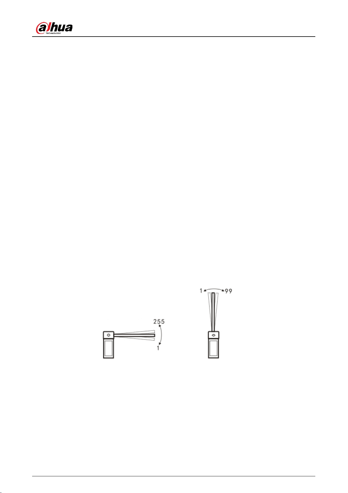
F-08 horizontal position adjustment
You can fine-tune the horizontal position of the boom by adjusting this parameter. The higher
the value, the more the boom will tilt upwards. The lower the value, the more the boom will tilt
downwards. The value is only valid when H-33 is set to 0. Otherwise, if the parameter is saved, it
will take effect when H-33 is set to 0.
F-09 vertical position adjustment
You can fine-tune the vertical position of the boom by adjusting this parameter. The larger the
value, the easier it will be for the boom to tilt upwards. The lower the value, the easier it will be
for the boom to tilt downwards. The value is only valid when H-33 is set to 0. Otherwise, if the
parameter is saved, it will take effect after H-33 is set to 0.
Adjust the boom position Figure 3-7
Adjust the horizontal position Adjust the vertical position
F-10 automatic delay closing time
Set F-10 to higher than 0, and after the boom gate is opened in place, the LED will show the
dxxx (xxx means seconds) countdown when no vehicles pass. The boom gate will automatically
close when the countdown reaches 0. If the boom gate receives an opening command during
the countdown, the countdown will restart. If the boom gate receives a stop command, the
countdown will stop. The automatic opening speed depends on the H-45 value of the advanced
menu.
F-13 self-learning speed after power-on
Set different speeds for learning the up limit and the down limit after powering on.
User’s Manual
18
1) After entering the menu, set the speed for learning the up limit first. The LED displays
"1-XX" (XX refers to the speed for learning the up limit). You can press the Open and
Close buttons to adjust the speed.
2) After setting the speed for learning the up limit, press Settings, and the LED displays
"2-XX" (XX refers to the speed for learning down limit). You can press the Open and
Close buttons to adjust the speed.
3) After setting the speeds, press Settings to save the configurations.
The settings do not take effect if you press Stop.
When manually adjusting the limit, the system learns the limits at the speed of 1-XX.
F-15 sensitivity of boom
While it is closing, if the boom is obstructed from moving for longer than the defined time, it
will open. Er.ob (see "3.4.2.3 Error Code") will be displayed on the LED.
3.4.2.2 Advanced Menu
Advanced Settings
Press and hold the Settings and Stop buttons for 2 seconds at the same time to go to the advanced
menu. The LED displays H-XX.
Advanced menu is for professionals and technical personnel.
Do not modify the items that are not listed in the table below, to avoid causing the boom gate
to malfunction.
Table 3-7 Some of the advanced menu items
Menu Function Default Range Description
H-02 Quick commissioning. — — See Advanced Settings Details.
H-03
Automatic delay closing
after a vehicle passes.
0 0–255
The boom gate automatically delays
closing by the defined time after the
vehicle passes. Unit: seconds.
H-07 Counting function. 1 0–10
Calculates the running times of the
boom gate. When it is set to 1, the
boom gate opens and closes after a
vehicle passes.
H-08 Automatic test. 0 0–5
Automatic aging test interval. 0 means
no automatic aging test, 2 means test
every 2 seconds. Unit: seconds.
H-09
Restores to its factory
default settings.
0 0–255
10: Restores to its factory default
settings.
H-17
The traffic light changes
when the boom opens
to the defined angle.
60 0–90
The red traffic light turns green when
the boom gate opens to the defined
angle.

User’s Manual
19
Menu Function Default Range Description
H-25
RS-485 communication
baud rate.
0 0–3
0: 115200, 1: 38400, 2: 19200, 3: 9600.
Leave it as the default.
H-26
RS-485 communication
address.
1 1–255 —
H-31
Enter the fleet mode
when opening the boom
gate by remote control.
0 0, 1 See Advanced Settings Details.
H-33
Learn the up and down
limits according to the
defined speed.
0 0–2
0: Learn the up and down limits.
1: Only learn the up limit
(recommended).
2: Only learn the down limit.
H-34
Adjust the up and down
limits manually.
None None
Only manually adjust the up and down
limits.
H-35
Adjust the up limit
manually.
None None
Only manually adjust the up limit.
Recommended for fence boom gate.
H-36
Adjust the down limit
manually.
None None
Only manually adjust the down limit.
Recommended when there is eave.
H-38 Coil signal buzzer. 0 0, 1 0: Buzz. 1: Not buzz.
H-45
Speed of auto delay
closing.
50
15–
100
Refer to this value when F-10 >0.
H-46
Auto opening time if low
voltage occurs.
0 0–50
0 means the boom gate does not open
when in low voltage. Unit: 0.1 seconds.
For example, when you set the time to
20, 2 seconds (20 × 0.1) after the
voltage is lower than the defined
threshold, the boom gate will
automatically open.
H-47
Auto opening when
reaching the low voltage
threshold.
21 15–22
The boom gate automatically opens
when the voltage meets the defined
threshold. Unit: volt.
Advanced Settings Details
H-02 quick commissioning
Table 3-8 Commissioning mode
Commissioning
Mode
Opening/Closing Speed
(second)
Commissioning
Mode
Opening/Closing Speed
(second)
3E1.2 1.2 3E1.5 1.5
3E2 2 3E3 3
3E4 4 3E5 5
3E6 6 — —
User’s Manual
20
Select one of the options, and then press Settings, the parameters of F-00 to F-07 are
automatically modified, and H-33 is automatically changed to 1. If the speed does not meet the
on-site requirements, you can fine-tune the parameters of F-00 to F-07.
This option can reduce the difficulty of on-site commissioning and reduce the commissioning
time.
H-03 automatic delay closing after vehicle passes
The range of H-03 is 0–255 (0 by default). Unit: 1 second. Different from F-10, H-03 means that
the countdown starts after the vehicle passes the coil or radar.
If there is an opening command during the countdown, the timer will be reset.
If the boom gate receives closing command, it will close immediately.
If it receives stop command, it will stop delay.
If the value is set to 0, the function will be turned off, and the boom gate closes after the
vehicle passes.
H-07 counting function
In some cases, the boom gate closes only when the number of opening times matches with the
closing times of ground sense relay. 0 means turning off the function. The value indicates the
maximum number of consecutive opening times.
H-08 automatic test
Interval of automatic aging test. 0 means the function is turned off. After the test is complete,
set this parameter to 0, or press Stop during the opening or closing process to exit automatic
test.
H-09 restore factory default settings
To prevent improper operation, set the parameter to 10, and then press Settings to restore
default settings. After the operation is complete, if you hear one buzz, the operation was
successful; and if it is 2 buzzes, the operation failed.
After restoring default settings, restart the device to make the settings take effect.
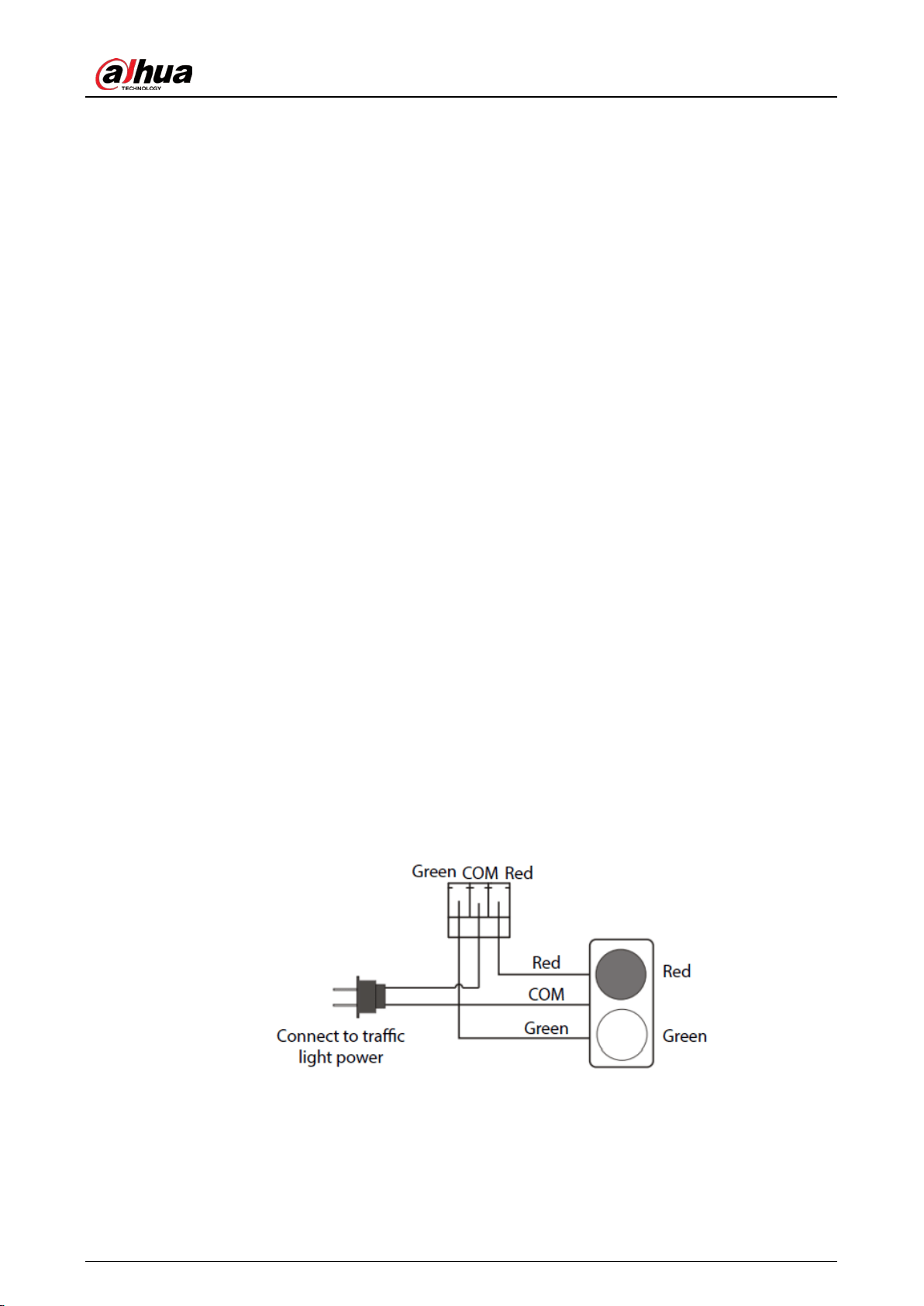
H-17 traffic light changes when the boom opens to the defined angle
When the boom gate opens to the defined angle, the relay of the traffic light interface changes
from COM and Red shorted to COM and Green shorted. After connecting to the traffic light
power supply, the traffic light interface can adapt to traffic lights of any voltage.
Traffic light wiring Figure 3-8
H-31 enter the fleet mode when opening the boom gate by remote control
Setting H-31 to 1 means that after opening the boom gate by remote control, it enters fleet
mode (the boom gate keeps open until a specified amount of vehicles pass), until you close
the boom gate. You can exit the fleet mode by remote control, or when the connected

User’s Manual
21
camera sends closing signal. The boom gate does not enter the fleet mode when it opens
after receiving opening command from the connected camera.
Set H-31 to 0, and when the boom gate is opened, press and hold Open on the remote
control for 4 seconds to enter the fleet mode.
H-33 define the up and down limits according the defined speed
After powering on the boom gate for the first time, it needs to find the limit of the gate before it
can enter the normal working mode.
The controller supports three limit finding modes:
0: Find both up limit and down limit. Press Open, the boom rises. The motor stops after the
boom finds the up limit. Press Close, the boom falls. The motor stops after the boom finds
the down limit. After both up and down limits are found, the boom gate enters the normal
working mode.
1: After powering on the controller for the first time, press Open, the boom rises. The boom
gate enters the normal working mode after it finds the up limit. The motor will stop. If you
press Close after first-time power-on, the boom rises. The boom gate enters the normal
working mode after it finds the up limit. The boom gate will be closed in normal working
mode.
2: After powering on the controller for the first time, press Close, the boom falls. The boom
gate enters the normal working mode after it finds the down limit. If you press Open after
first-time power-on, the boom gate closes first, finds the down limit, and then it can open
in the normal working mode. This mode is ideal for scenes blocked with eaves.
H-34 adjust the up and down limits manually
You can use this command to manually set the up and down positions of the boom, so that it is
more intuitive to adjust the up and down positions of the boom.
After entering the H-34 command, the LED shows L-00, and then the boom falls. After the
boom finds the down limit, the buzzer beeps, and the LED changes to L-01. Then the boom
rises, the buzzer beeps, and the LED changes to L-02, meaning that the up limit has been
found. At this moment, the gate stops, and you need to manually find the vertical and
horizontal positions of the boom:
1) Press and hold Close, the boom works in the closing direction, until it is in the required
vertical position.
2) Press Settings to confirm the vertical position, then the LED shows L-03, meaning that
the boom gate finishes finding the vertical position.
3) Continue to press and hold Close until the boom is in the desired horizontal position.
4) Press Settings to confirm the horizontal position. After you hear the sound from the
buzzer, the boom gate goes back to the normal working status.
If the boom does not reach the desired position after manual adjustment, you can press
Open or Close to adjust the position. During the adjustment process, if you do not release
the Open or Close button when the boom reaches the up or down limit, the controller will
stop the motor, and the buzzer makes continuous buzzes for alarm.
If H-33 is set to 0, the boom gate can work normally after manual adjustment. If H-33 is set
to 1, the parameters manually adjusted are saved, and they will take effect only when H-33
is set to 0.
The parameters adjusted through H-34 will influence F-08 and F-09. You can view the
adjustment value of horizontal and vertical positions through F-08 and F-09.
User’s Manual
22
You can use H-34, configure F-08 and F-09 to adjust the vertical and horizontal positions,
but using H-34 is more intuitive.
H-35 adjust the up limit manually (recommended for straight boom gate or fence boom gate,
with boom length of 5 meters or more)
After entering the H-35 command, the LED shows L-00, and then the boom rises. After the
boom finds the up limit, the buzzer beeps, and the LED changes to L-01, meaning that the
up limit has been found. At this moment, the gate stops, and you need to manually find the
vertical and horizontal positions of the boom:
1) Press and hold Close, the boom works in the closing direction, until it is in the required
vertical position.
2) Press Settings to confirm the vertical position, then the LED shows L-02, meaning that
the boom gate finishes finding the vertical position.
3) Continue to press and hold Close until the boom is in the desired horizontal position.
4) Press Settings to confirm the horizontal position. After you hear the sound from the
buzzer, the boom gate goes back to the normal working status.
If the boom does not reach the desired position after adjustment, you can press Open or
Close to adjust the position. During the adjustment process, if you do not release the Open
or Close button when the boom reaches the up or down limit, the controller will stop the
motor, and the buzzer makes continuous buzzes for alarm.
If H-33 is set to 1, the boom gate can work normally after manual adjustment. If H-33 is set
to 0, the parameters manually adjusted are saved, and they will take effect only when H-33
is set to 1.
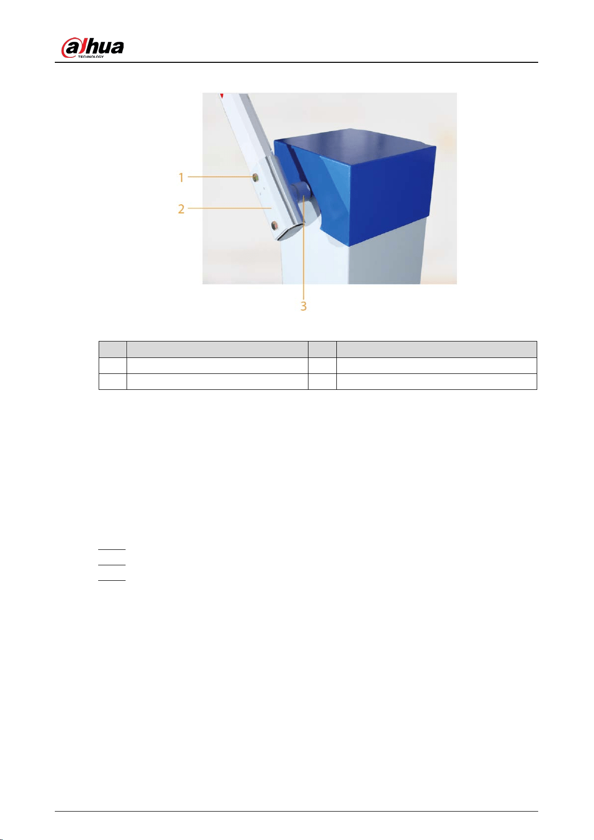
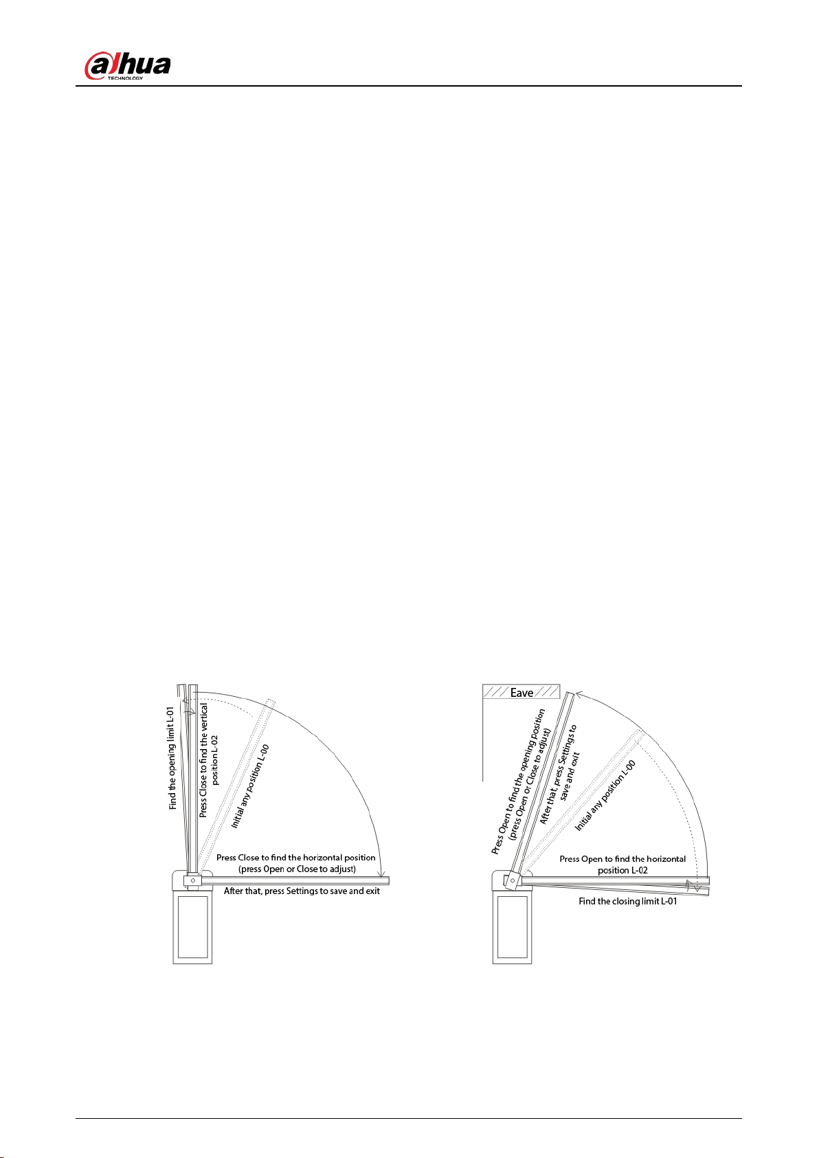
Adjust the up limit manually Figure 3-9
H-35 adjust the up limit manually (recommended for
straight boom gate or fence boom gate, with boom
length of 5 meters or more)
The boom gate works at the speed of F-13 value
H-36 adjust the down limit manually
(recommended when there is an eave)
The boom gate works at the speed of F-13
value
H-36 adjust the down limit manually (recommended when there is an eave)
After entering the H-36 command, the LED shows L-00, and then the boom rises. After the
boom finds the down limit, the buzzer beeps, and the LED changes to L-01, meaning that

User’s Manual
23
the down limit has been found. At this moment, the gate stops, and you need to manually
find the vertical and horizontal positions of the boom:
1) Press and hold Open, the boom works in the opening direction, until it is in the
required horizontal position.
2) Press Settings to confirm the horizontal position, then the LED shows L-02, meaning
that the boom gate finishes finding the horizontal position.
3) Continue to press and hold Open until the boom is in the desired opening position.
4) Press Settings to confirm the position. After you hear the sound from the buzzer, the
boom gate goes back to the normal working status.
If the boom does not reach the desired position after adjustment, you can press Open or
Close to adjust the position. During the adjustment process, if you do not release the Open
or Close button when the boom reaches the up or down limit, the controller will stop the
motor, and the buzzer makes continuous buzzes for alarm.
If H-33 is set to 2, the boom gate can work normally after manual adjustment. If H-33 is set
to 0 or 1, the parameters manually adjusted are saved, and they will take effect only when
H-33 is set to 2.
H-38 coil signal buzzer
You can set whether the boom gate buzzes when it receives coil or radar signals for
anti-smashing. The parameter is 0 by default, meaning no buzzes when the boom gate receives
coil or radar signals, 1 means the boom gate buzzes.
H -45 speed of auto delay closing
When F-10 (automatic delay closing time) is greater than 0, after the countdown finishes, the
boom gate opens at H-45 speed. The greater the value is, the faster the speed will be. When the
spring tension is large, the H-45 speed is too small, making the boom open when it is
obstructed during closing, you can increase the value appropriately.
H-46 auto opening time if low voltage occurs
This parameter defines the automatic opening function in case of power failure. It works with
H-47. When the power supply voltage is lower than the defined H-47 value, and the low voltage
continues for the defined H-46 value, the boom gate automatically opens. After it is opened, the
digital tube displays loxx (xx indicates the value of H-47). This function is available when an
ultracapacitor backup power module is installed. If H-46 is set to 0, it means that the function is
turned off.
H-47 auto opening when reaching the low voltage threshold
This parameter defines the voltage that the boom gate opens in case of power failure. It works
with H-46. In case of power failure, the boom gate automatically opens when the voltage is
lower than the defined H-47 value for more than the time defined in H-46.
3.4.2.3 Error Code
When the controller detects an exception, error codes as shown in the following table will be
displayed.
Table 3-9 Error code
Error Code Reason
Er.ob The boom reverses or stops when it is obstructed during the opening process.
User’s Manual
24
Error Code Reason
Er. 7 Alarm when someone rises the boom manually.
3.4.2.4 LED Message Display
Table 3-10 LED message display
Message Description
IdLE
The plug of the motor sensor is not inserted or the motor sensor fails, which might be
caused by loosen cable.
STOP The boom gate stops working.
cLOS The boom gate is closing.
OPEN The boom gate is opening.
HOLd The boom gate is opened.
LocK The boom gate is locked, and it enters the fleet mode.
uPxx xx is the number of opening times after enabling the counting function.
dxxx
The time that auto delays in closing the boom gate. xxx refers to the countdown time
(only displays after enabling the auto delay in closing function).
Fcxx Software version. xx refers to the version. The larger the value, the newer the version.
Loxx Automatically open the boom gate in low voltage. xx refers to the H-47 value.
Value
The running times of the boom gate. If less than 100,000 times, the entire number
will be displayed; if more than 100,000 times, the number will be replaced by "_". For
example, 23_ means 230,000 times.
Adjusting Spring Balance 3.5
The spring of boom gate is adjusted by default.
Do not change the boom and adjust the boom length.
The spring length is for reference only.
The spring is a wear part, and you need to maintain and replace it regularly.
Select the spring. Step 1
Table 3-11 Select spring
Boom Type Boom Length L (m) Spring Cable Diameter (mm) Remarks
Straight Boom with
Rubber Strip
6 ≥ L > 5.3 Φ6.0 + Φ4.5
Cable color.
Φ4.5 spring:
red
Φ5.5 spring:
blue
Φ6.0 spring:
green
Φ6.8 spring:
Straight Boom with
Rubber Strip
5.3 ≥ L ≥ 4.3 Φ5.5 + Φ4.5
Straight Boom with
Rubber Strip
4.3 > L ≥ 3.5 Φ4.5 + Φ4.5
Straight Boom with
Rubber Strip
3.5 > L ≥ 3 Φ5.5
User’s Manual
25
Boom Type Boom Length L (m) Spring Cable Diameter (mm) Remarks
Straight Boom with
Rubber Strip
L < 3 Φ4.5
yellow
Telescopic Boom 3–4 Φ4.5 + Φ4.5
Telescopic Boom 4–5 Φ4.5 + Φ5.5
Telescopic Boom 5–6 Φ4.5 + Φ6
Folding Boom 5 ≥ L ≥ 4.3 Φ5.5 + Φ4.5
Folding Boom 4.3 > L ≥ 3 Φ4.5 + Φ4.5
Folding Boom L < 3 Φ4.5
Fence Boom (two
sections)
L = 4.5 Φ6.0 + Φ6.0
Fence Boom (two
sections)
4.5 > L ≥ 4 Φ6.0 + Φ5.5
Fence Boom (two
sections)
4 > L ≥ 3.5 Φ5.5 + Φ5.5
Fence Boom (two
sections)
3.5 > L ≥ 3 Φ5.5 + Φ4.5
Fence Boom (two
sections)
L < 3 Φ4.5 + Φ4.5
Remove the spring. Step 2
1) Open the boom gate to make the boom stay at 90°.
2) Loosen the spring lock nut, use a hexagonal wrench to remove the spring adjustment
screw (M8 × 140 mm), and then take out the spring from the hook.
The installation procedure is the opposite of the removing process.
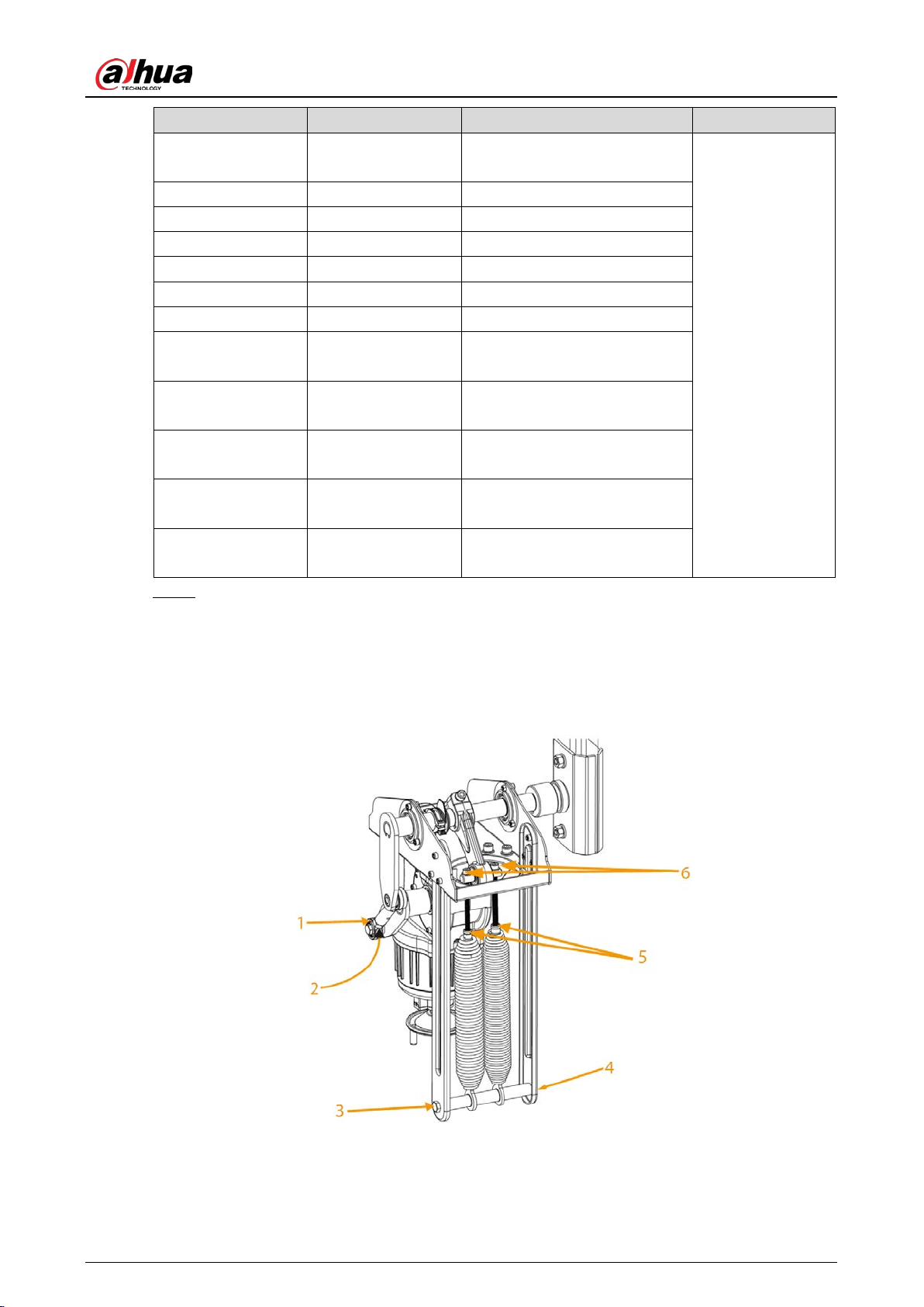
Position of spring Figure 3-10
Table 3-12 Structure description
User’s Manual
26
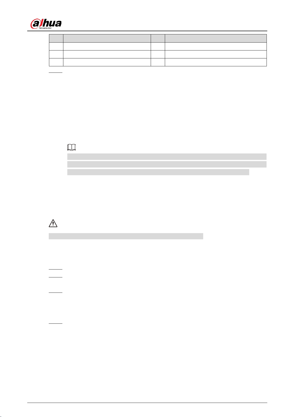
No. Description No. Description
1 Spring adjustment nut 4 Hook
2 M12 lock nut 5 Spring lock nut
3 M10 screw 6 Spring adjustment screw (M8 × 140 mm)
Adjust the spring. Step 3
1) Power off the boom gate.
2) Rotate the motor hand wheel to make the boom move in the direction of closing the
boom gate.
After rotating the hand wheel to the nearly-horizontal position, if the hand wheel jitters
during rotation, you need to tighten the spring. Rotate the hand wheel in the direction
of opening the boom gate, and when rotate it to the nearly-vertical position, if the
hand wheel jitters, you need to loosen the spring. Try several ways according to the
previous description to rotate the hand wheel, until the hand wheel works smooth, and
the spring is balanced.
You can check whether the spring is balanced by powering on the boom gate, and
observing the working status of the boom. The spring is too tight if the boom dithers during
the opening process, and is too loose if the boom dithers during the closing process.
Remote Control 3.6
The remote control receiver comes with the controller is a learning code receiver.
The remote control can work normally after it exits the unpairing status.
Pairing
Unplug the remote control receiver (or power off the boom gate). Step 1
Press and hold the Open button of the remote control, and then plug in the remote control Step 2
receiver (or power on the boom gate).
When the indicator (the indicator inside the receiver) flashes slowly, the remote control Step 3
starts pairing (about 2 seconds). Release the Open button, and then press and hold the
Close button for about 5 seconds. If the indicator is solid on, the pairing was successful.
After the indicator flashes slowly again, you can start pairing the second remote control.
Press and hold the Close button of the second remote control for 3 seconds. If the indicator Step 4
is solid on, the second remote control was successfully paired. You can continue to pair
other remote controls similarly.
If there is no pairing operation after 1 minute, the remote control automatically exits the
pairing status, and enters normal working status (or press and hold the Open button of the
paired remote control over 3 seconds to exit the pairing status). A maximum of 40 remote
controls can be paired. If there are more than 40 remote controls, the records of remote
controls that are paired earlier will be covered.

User’s Manual
27
Unpairing
Unplug the remote control receiver (or power off the boom gate). Step 1
Press and hold the Close button of the paired remote control, and then plug in the remote Step 2
control receiver (or power on the boom gate).
When the indicator flashes quickly, the remote control enters the unpairing status. Release Step 3
the Close button, and then press and hold the Close button for 5 seconds. If the indicator is
solid on, all the remote controls are successfully unpairded. 6 seconds later, the remote
control automatically switches to the normal working status.

User’s Manual
28
4 Maintenance
Clean the casing surface to avoid dust and litter.
Check the fasteners are well tightened once a month, and fasten them when necessary.
Check spring balance after the boom gate runs every 300,000 times; replace the spring with a
new one after the boom gate runs 1 million times or 12 months, to avoid spring fracture due to
overuse.
Check and replace (if necessary) wear parts every 6 months by professionals.
If the remote control distance is too close, check whether the receiver is shielded by metal
objects, or the battery of the remote control is low. The remote control distance might be
reduced if there are multiple devices of the same frequency interference in the area, or under
severe weather conditions such as rain, fog, wind and snow.

User’s Manual
29
FAQ Appendix 1
1. 1. Power on the boom gate, open or close it by remote control. The boom does not work.
Check whether the controller power indicator is on. If not, check whether the fuse is in
good condition.
Check whether the remote control matches with the boom gate, or the battery is low.
There is frequency interference near the remote control. Press the control button on the
controller to check whether the boom works (if there is no button, short COM, Open and
Close).
External protection circuit failure, or the circuit is in a protected status. Check whether the
radar indicator and the coil indicator are on.
2. The boom gate stops finding the up and down limit in the closing process after power-on.
Check whether the boom is installed. When the spring is installed, the boom gate cannot work
without the boom.
3. The boom gate opens and closes too fast after powered on for the first time.
Check whether F-13 power-on self-learning speed is too great. If yes, reduce the 1-XX and 2-XX
values of F-13.
4. The bar cannot be in place when manually locating the limit position, and the buzzer will
alarm.
Check whether F-13 power-on self-learning speed is too small. If yes, increase the 1-XX and 2-XX
values of F-13, and try again.
5. The controller displays IDLE.
Check whether motor sensor plug is inserted. If not, insert it.
Check the motor sensor, and replace it if it fails.
6. The controller resets when the boom gate is running.
Check whether there is short circuit inside the motor. Measure the phase line resistance
with a multimeter.
Check the controller, and replace it if it fails.
7. The boom gate automatically opens during the closing process.
Check whether F-15 sensitivity of boom is too small. Increase the value.
Check whether coil or radar has abnormal signals by checking whether the coil or radar
signal indicator flashes abnormally.
8. The boom dithers obviously when the boom gate is opened in place.
Decrease F-06.
Decrease F-06 and F-02.
Decrease F-00.
9. The boom dithers obviously when the boom gate is closed in place.
Decrease F-07.
Decrease F-07 and increase F-03.
10. The remote control distance is too close.
Check whether the battery voltage of the remote control is too low. If yes, replace the
battery.
Check whether there are power lines or severe electromagnetic interference nearby. If yes,
replace the remote control with a high-power one.

User’s Manual
30
11. The remote control failed to learn.
The remote control does not match the receiver. Contact the manufacturer to confirm whether
it is the matched remote control.
12. The boom is not vertical after the boom opens.
Check whether the vertical position value of the controller is properly configured. If H-33 is set
to 0, adjust the F-08 value of the controller.
13. The boom is not horizontal after the boom closes.
Check whether the horizontal position value of the controller is properly configured. If H-33 is
set to 0, adjust the F-09 value of the controller.

User’s Manual
31
Cybersecurity Recommendations Appendix 2
Cybersecurity is more than just a buzzword: it’s something that pertains to every device that is
connected to the internet. IP video surveillance is not immune to cyber risks, but taking basic steps
toward protecting and strengthening networks and networked appliances will make them less
susceptible to attacks. Below are some tips and recommendations from Dahua on how to create a
more secured security system.
Mandatory actions to be taken for basic device network security:
1. Use Strong Passwords
Please refer to the following suggestions to set passwords.
The length should not be less than 8 characters.
Include at least two types of characters; character types include upper and lower case
letters, numbers and symbols.
Do not contain the account name or the account name in reverse order.
Do not use continuous characters, such as 123, abc, etc.
Do not use overlapped characters, such as 111, aaa, etc.
2. Update Firmware and Client Software in Time
According to the standard procedure in Tech-industry, we recommend to keep your device
(such as NVR, DVR, IP camera, etc.) firmware up-to-date to ensure the system is equipped
with the latest security patches and fixes. When the device is connected to the public
network, it is recommended to enable the "auto-check for updates" function to obtain
timely information of firmware updates released by the manufacturer.
We suggest that you download and use the latest version of client software.
"Nice to have" recommendations to improve your device network security:
1. Physical Protection
We suggest that you perform physical protection to device, especially storage devices. For
example, place the device in a special computer room and cabinet, and implement well-done
access control permission and key management to prevent unauthorized personnel from
carrying out physical contacts such as damaging hardware, unauthorized connection of
removable device (such as USB flash disk, serial port), etc.
2. Change Passwords Regularly
We suggest that you change passwords regularly to reduce the risk of being guessed or cracked.
3. Set and Update Passwords Reset Information Timely
The device supports password reset function. Please set up related information for password
reset in time, including the end user’s mailbox and password protection questions. If the
information changes, please modify it in time. When setting password protection questions, it is
suggested not to use those that can be easily guessed.
4. Enable Account Lock
The account lock feature is enabled by default, and we recommend you to keep it on to
guarantee the account security. If an attacker attempts to log in with the wrong password
several times, the corresponding account and the source IP address will be locked.
5. Change Default HTTP and Other Service Ports
We suggest you to change default HTTP and other service ports into any set of numbers

User’s Manual
32
between 1024–65535, reducing the risk of outsiders being able to guess which ports you are
using.
6. HTTPS
We suggest you to enable HTTPS, so that you visit Web service through a secure communication
channel.
7. MAC Address Binding
We recommend you to bind the IP and MAC address of the gateway to the device, thus reducing
the risk of ARP spoofing.
8. Assign Accounts and Privileges Reasonably
According to business and management requirements, reasonably add users and assign a
minimum set of permissions to them.
9. Disable Unnecessary Services and Choose Secure Modes
If not needed, it is recommended to turn off some services such as SNMP, SMTP, UPnP, etc., to
reduce risks.
If necessary, it is highly recommended that you use safe modes, including but not limited to the
following services:
SNMP: Choose SNMP v3, and set up strong encryption passwords and authentication
passwords.
SMTP Choose TLS to access mailbox server.
FTP Choose SFTP, and set up strong passwords.
AP hotspot: Choose WPA2-PSK encryption mode, and set up strong passwords.
10. Audio and Video Encrypted Transmission
If your audio and video data contents are very important or sensitive, we recommend that you
use encrypted transmission function, to reduce the risk of audio and video data being stolen
during transmission.
Reminder: encrypted transmission will cause some loss in transmission efficiency.
11. Secure Auditing
Check online users: we suggest that you check online users regularly to see if the device is
logged in without authorization.
Check device log: By viewing the logs, you can know the IP addresses that were used to log
in to your devices and their key operations.
12. Network Log
Due to the limited storage capacity of the device, the stored log is limited. If you need to save
the log for a long time, it is recommended that you enable the network log function to ensure
that the critical logs are synchronized to the network log server for tracing.
13. Construct a Safe Network Environment
In order to better ensure the safety of device and reduce potential cyber risks, we recommend:
Disable the port mapping function of the router to avoid direct access to the intranet
devices from external network.
The network should be partitioned and isolated according to the actual network needs. If
there are no communication requirements between two sub networks, it is suggested to
use VLAN, network GAP and other technologies to partition the network, so as to achieve
the network isolation effect.
Establish the 802.1x access authentication system to reduce the risk of unauthorized access
to private networks.

User’s Manual
33
Enable IP/MAC address filtering function to limit the range of hosts allowed to access the
device.
More information
Please visit Dahua official website security emergency response center for security announcements
and the latest security recommendations.

User’s Manual