SDS1000X-E&SDS1000X-U User Manual
SDS1000X-E
SDS1000X-U
Digital Oscilloscope
User Manual
EN05B
Aug.2021

SDS1000X-E&SDS1000X-U User Manual
I
WWW.SIGLENT.COM
Copyright and Declaration
Copyright
SIGLENT TECHNOLOGIES CO., LTD. All Rights Reserved.
Trademark Information
SIGLENT is the registered trademark of SIGLENT TECHNOLOGIES CO., LTD.
Declaration
SIGLENT products are protected by patent law in and outside of P.R.C.
SIGLENT reserves the right to modify or change parts of or all the specifications or pricing
policies at company’s sole decision.
Information in this publication replaces all previously corresponding material.
Any way of copying, extracting or translating the contents of this manual is not allowed
without the permission of SIGLENT.
Product Certification
SIGLENT guarantees this product conforms to the national and industrial stands in China
and other international stands conformance certification is in progress.
Contact Us
If you have any problem or requirement when using our products, please contact
SIGLENT
TECHNOLOGIES CO., LTD
Add:Blog No.4 & No.5, Antongda Industrial Zone, 3rd Liuxian Road, Bao’an District,
Shenzhen, 518101, China
Tel:400-878-0807
E-mail:sales@siglent.com
http://www.siglent.com

SDS1000X-E&SDS1000X-U User Manual
II
WWW.SIGLENT.COM
Introduction
This user manual includes important safety and installation information related to the
SDS1000X-E and SDS1000X-U series oscilloscopes, and includes simple tutorials for basic
operation of the oscilloscope.
The series includes the following models:
Model
Analog Bandwidth
SDS1204X-E
200 MHz bandwidth, 4-channel, 1 GSa/s Sample rate
SDS1104X-E
100 MHz bandwidth, 4-channel, 1 GSa/s Sample rate
SDS1202X-E
200 MHz bandwidth, 2-channel, 1 GSa/s Sample rate
SDS1104X-U
100 MHz bandwidth, 4-channel, 1 GSa/s Sample rate

SDS1000X-E&SDS1000X-U User Manual
III
WWW.SIGLENT.COM
General Safety Summary
Carefully read the following safety precautions to avoid any personal injury or damage to
the instrument and any products connected to it. To avoid potential hazards, please use
the instrument as specified.
Use Proper Power Line
Only the power cord designed for the instrument and authorized by local country could be
used.
Ground the Instrument
The instrument is grounded through the protective earth conductor of the power line. To
avoid electric shock, please make sure the instrument is grounded correctly before
connecting its input or output terminals.
Connect the Signal Wire Correctly
The potential of the signal wire is equal to the earth, so do not connect the signal wire to a
high voltage.
Look Over All Terminals’ Ratings
To avoid fire or electric shock, please look over all ratings and sign instruction of the
instrument. Before connecting the instrument, please read the manual carefully to gain
more information about the ratings.
Use Proper Overvoltage Protection
Make sure that no overvoltage (such as that caused by a thunderstorm) can reach the
product, or else the operator might expose to danger of electrical shock.
Electrostatic Prevention
Operate in an electrostatic discharge protective area environment to avoid damages
induced by static discharge. Always ground both the internal and external conductors of
the cable to release static before connecting.
Keep Well Ventilation
Inadequate ventilation may cause increasing of temperature, which will eventually
damage the instrument. So keep well ventilation and inspect the intake and fan regularly.
Avoid Circuit or Components Exposed
Do not touch exposed contacts or components when the power is on.
Use proper Fuse
Use only the specified fuse.

SDS1000X-E&SDS1000X-U User Manual
IV
WWW.SIGLENT.COM
Do Not Operate Without Covers
Do not operate the instrument with covers or panels removed.
Do Not Operate With Suspected Failures.
If you suspect damage occurs to the instrument, have it inspected by qualified service
personnel before further operations. Any maintenance, adjustment or replacement
especially to circuits or accessories must be performed by SIGLENT authorized personnel.
Do Not Operate in Wet Conditions.
In order to avoid short circuiting to the interior of the device or electric shock, please do
not operate in a humid environment.
Do Not Operate in an Explosive Atmosphere.
In order to avoid damages to the device or personal injuries, it is important to operate the
device away from an explosive atmosphere.
Keep Product Surfaces Clean and Dry.
To avoid the influence of dust and/or moisture in air, please keep the surface of device
clean and dry.
Handling Safety
Please handle with care during transportation to avoid damages to buttons, knob
interfaces and other parts on the panels.
Only probe assemblies which meet the manufacturer’s specifications shall be used.
When use 2X/…/10000X probe assemblies, the probe assemblies shall be insulated from
the measured circuits by double or reinforced insulation.
All probe assemblies should meet the requirements of UL 61010-031 and CAN/CSA-C22.2
No. 61010-031-07.
Not to position the equipment so that it is difficult to operate the disconnecting device
(detachable plug).
If the equipment is used in a manner not specified by the manufacturer, the protection
provided by the equipment may be impaired
SDS1000X-E&SDS1000X-U User Manual
V
WWW.SIGLENT.COM
Safety Terms and Symbols
Terms in this Manual. These terms may appear in this manual:
WARNING
Warning statements indicate the conditions or practices that
could result in injury or loss of life.
CAUTION
Caution statements indicate the conditions or practices that
could result in damage to this product or other property.
Terms on the product. These terms may appear on the product:
DANGER Indicates direct injuries or hazards that may happen.
WARNING Indicates potential injuries or hazards that may happen.
CAUTION Indicates potential damages to the instrument or other property that may
happen.
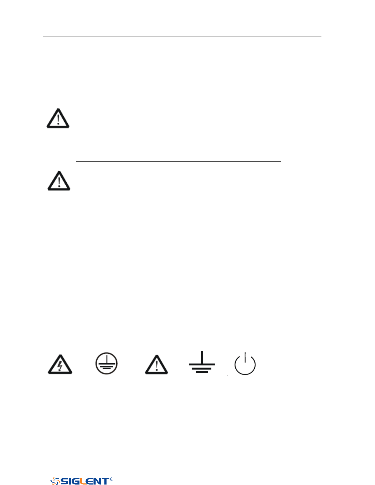
Symbols on the product. These symbols may appear on the product:
Hazardous protective Earth Warning Test Power Switch
Voltage Terminal Ground
If find such symbols on the product, consult the manual to find out the nature of the
potential hazard and the actions which have to be taken

SDS1000X-E&SDS1000X-U User Manual
VI
WWW.SIGLENT.COM
Measurement Category
Measurement Categories
This oscilloscope can make measurements in other circuits that are not directly connected
to mains.
WARNING
This oscilloscope can only be used for measurements within its specified
measurement categories. Not to use the product for measurements within
other measurement categories, such as CAT II, CAT III, CAT IV.
Not to use the equipment for measurements on mains circuits
Measurement Category Definitions
Measurement category II is for measurements performed on circuits directly connected to
the low voltage installation. Examples are measurements on household appliances,
portable tools and similar equipment.
Measurement category III is for measurements performed in the building installation.
Examples are measurements on distribution boards, circuit-breakers, wiring, including
cables, bus-bars, junction boxes, switches, socket-outlets in the fixed installation, and
equipment for industrial use and some other equipment, for example. Stationary motors
with permanent connection to the fixed installation.
Measurement category IV is for measurements performed at the source of the low-voltage
installation. Examples are electricity meters and measurements on primary over current
protection devices and ripple control units.
SDS1000X-E&SDS1000X-U User Manual
VII
WWW.SIGLENT.COM
Working Environment
Environment
This instrument is intended for indoor use and should be operated in a clean, dry
environment.
Temperature
Operating: 0℃ to +40℃
Non-operation:-20℃ to +60℃
Note: Direct sunlight, radiators, and other heat sources should be taken into account when
assessing the ambient temperature.
Humidity
Operating: 85% RH, 40 ℃, 24 hours
Non-operating: 85% RH, 65 ℃, 24 hours
Altitude
Operating: less than 3 Km
Non-operation: less than 15 Km
Installation (overvoltage) Category
This product is powered by mains conforming to installation (overvoltage) category II.
WARNING
Make sure that no overvoltage (such as that caused by thunderbolt) can reach
the product, or else the operator might expose to danger of electric shock.
Installation (overvoltage) Category Definitions
Installation (overvoltage) category I refers to signal level which is applicable to equipment
measurement terminals connected to the source circuit. In these terminals, precautions
are done to limit the transient voltage to the corresponding low level.
Installation (overvoltage) category II refers to the local power distribution level which is
applicable to equipment connected to the AC line (AC power).
Degree of Pollution
The oscilloscopes may be operated in environments of Pollution Degree II.
Note: Degree of Pollution II refers to a working environment which is dry and
non-conductive pollution occurs. Occasional temporary conductivity caused by
condensation is expected.
SDS1000X-E&SDS1000X-U User Manual
VIII
WWW.SIGLENT.COM
IP Rating
IP20 (as defined in IEC 60529).
Ventilation Requirement
This oscilloscope uses fan to force cooling. Please make sure that the air intake and
exhaust areas are free from obstructions and have free air. When using the oscilloscope in
a bench-top or rack setting, provide at least 10 cm clearance beside, above and behind
the instrument for adequate ventilation.
WARNING
Inadequate ventilation may cause temperature increase which would damage
the instrument. So please keep the instrument well ventilated during operation
and inspect the intake and fan regularly.
AC Power and Ground Connections
The instrument operates with a single-phase, 100 to 240 Vrms (+/-10%) AC power at 50/60
Hz (+/-5%), or single-phase 100 - 120 Vrms (+/-10%) AC power at 400Hz (+/-5%).
No manual voltage selection is required because the instrument automatically adapts to
line voltage.
Depending on the type and number of options and accessories (probes, PC port plug-in,
etc.), the SDS1xx2X-E can consume up to 25 W of power, the SDS1xx4X-E can consume up
to 25 W of power, the SDS1xx4X-U can consume up to 50 W of power.
Note: The instrument automatically adapts to the AC line input within the following
ranges:
Voltage Range:
90 - 264 Vrms
90 - 132 Vrms
Frequency Range:
47 - 63 Hz
380 - 420 Hz
The instrument includes a grounded cord set containing a molded three-terminal
SDS1000X-E&SDS1000X-U User Manual
IX
WWW.SIGLENT.COM
polarized plug and a standard IEC320 (Type C13) connector for making line voltage and
safety ground connection. The AC inlet ground terminal is connected directly to the frame
of the instrument. For adequate protection against electrical shock hazard, the power cord
plug must be inserted into a mating AC outlet containing a safety ground contact. Use only
the power cord specified for this instrument and certified for the country of use.
WARNING
Electrical Shock Hazard!
Any interruption of the protective ground conductor within or outside of the
scope or disconnection of the safety ground terminal creates a hazardous
situation.
Intentional interruption is prohibited.
The position of the oscilloscope should allow easy access to the socket. To make the
oscilloscope completely power off, unplug the instrument power cord from the AC socket.
The power cord should be unplugged from the AC outlet if the scope is not to be used for
an extended period of time.
CAUTION
The outer shells of the front panel terminals (CH1, CH2, CH3, CH4, EXT) are
connected to the instrument’s chassis and therefore to the safety ground.
General Care and Cleaning
Care
Do not store or leave the instrument in direct sunshine for long periods of time.
WARNING
To avoid damages to the instrument or probe, please do not leave them in fog,
liquid, or solvent.
Cleaning
Please perform the following steps to clean the instrument and probe regularly according
SDS1000X-E&SDS1000X-U User Manual
X
WWW.SIGLENT.COM
to its operating conditions.
Disconnect the instrument from all power sources, and then clean it with a soft wet cloth.
Clean the loose dust on the outside of the instrument and probe with a soft cloth. When
cleaning the LCD, take care to avoid scarifying it.
WARNING
To avoid damages to the surface of the instrument and probe, please do not
use any corrosive liquid or chemical cleanser.
WARNING
Make sure that the instrument is completely dry before restarting it to avoid
short circuits or personal injuries.
Safety Compliance
This section lists the safety standards with which the product complies.
U.S. nationally recognized testing laboratory listing
■ UL 61010-1:2012/R:2018-11. Safety Requirements for Electrical Equipment for
Measurement, Control, and Laboratory Use – Part 1: General Requirements.
■ UL 61010-2-030:2018. Safety Requirements for Electrical Equipment for Measurement,
Control, and Laboratory Use – Part2-030: Particular requirements for testing and
measuring circuits.
Canadian certification
■ CAN/CSA-C22.2 No. 61010-1:2012/A1:2018-11. Safety Requirements for Electrical
Equipment for Measurement, Control, and Laboratory Use – Part 1: General
Requirements.
■ CAN/CSA-C22.2 No. 61010-2-030:2018. Safety Requirements for Electrical Equipment
for Measurement, Control, and Laboratory Use – Part 2-030: Particular requirements for
testing and measuring circuits.

SDS1000X-E&SDS1000X-U User Manual
XI
WWW.SIGLENT.COM
Résumé général de sûreté
Lisez soigneusement les mesures de sécurité suivantes pour éviter n'importe quelles
blessures ou les dommages à l'instrument et à tous les produits se sont reliés à eux. Pour
éviter des risques, utilisez svp l'instrument comme indiqué.
Employez la ligne à haute tension appropriée
Seulement le cordon de secteur conçu pour l'instrument et autorisé par le pays local a pu
être employé.
A rectifié l'instrument.
L'instrument est fondu par le conducteur protecteur de terra de la ligne à haute tension.
Pour éviter la décharge électrique, le conducteur moulu doit être relié à la terre.
Assurez-vous que l'instrument est fondu correctement avant de relier ses bornes d'entrée
ou de rendement.
Reliez le fil de signal correctement.
Le potentiel de l'au sol de fil de signal est égal à la terre, ainsi ne relie pas le fil de signal à
une tension.
Regardez estimations au-dessus de toutes les bornes des'
Pour éviter le feu ou la décharge électrique, regardez svp au-dessus de toutes les
estimations et instruction de signe de l'instrument. Avant de relier l'instrument, lisez svp le
manuel soigneusement pour obtenir plus d'informations sur les estimations.
Employez la protection appropriée de surtension
Assurez-vous qu'aucune surtension (comme cela provoqué par un orage) ne peut
atteindre le produit, ou bien l'opérateur pourrait exposer au danger du choc électrique.
Empêchement électrostatique
Fonctionnez dans un environnement protecteur de secteur de décharge électrostatique
pour éviter des dommages induits par décharge statique. A toujours rectifié les
conducteurs internes et externes du câble pour libérer la charge statique avant de se
relier.
La ventilation insatisfaisante de ventilation
bonne de subsistance peut causer l'augmentation de la température, qui endommagera
par la suite l'instrument. Gardez ainsi la ventilation bonne et inspectez la prise et éventez
régulièrement.
Évitez le circuit ou les composants exposés
ne touchent pas les contacts ou les composants exposés quand le courant passe.

SDS1000X-E&SDS1000X-U User Manual
XII
WWW.SIGLENT.COM
Employez l'utilisation appropriée
de fusible seulement le fusible indiqué.
Ne fonctionnez pas sans couvertures
n'actionnent pas l'instrument des couvertures ou des panneaux étant coupés.
Ne fonctionnez pas avec des échecs suspectés.
Si vous suspectez les dommages se produisent à l'instrument, l'ont inspecté par le
personnel de service qualifié avant d'autres opérations. N'importe quel entretien,
ajustement ou remplacement particulièrement aux circuits ou aux accessoires doivent être
exécutés par le personnel autorisé par SIGLENT.
Ne fonctionnez pas en conditions humides.
Afin d'éviter de court-circuiter à l'intérieur du dispositif ou de la décharge électrique, svp
ne fonctionnez pas dans un environnement humide.
Do Not Operate in an Explosive Atmosphere.
Ne fonctionnez pas dans une atmosphère explosive.
Afin d'éviter d'endommager le dispositif ou les blessures, il est important d'utiliser le
dispositif loin à partir d'une atmosphère explosive.
Maintenez les surfaces de produit propres et sèches.
Pour éviter l'influence de la poussière et/ou de l'humidité en air, maintenez svp la surface
du dispositif propre et sèche.
En manipulant la sûreté
manipulez svp avec soin pendant le transport pour éviter d'endommager des boutons,
des interfaces de bouton et d'autres parties sur les panneaux.
Sondez seulement les ensembles qui répondent aux caractéristiques du fabricant seront
employés.
Quand des sondes de l'utilisation 5X/10X/50X/100X/500X/1000X, les sondes seront
isolées des circuits mesurés par le double ou l'isolation renforcée.
Toutes les sondes devraient répondre aux exigences de l'UL 61010-031 et du CAN/CS
A-C22.2 No. 61010-031-07
Le corps ou l'opérateur responsable devrait se référer au manuel d'instruction pour
préserver la protection se permettent par l'équipement. Si l'équipement est utilisé en
quelque sorte non indiqué par le fabricant, la protection fournie par l'équipement peut
être altérée.
On ne permet à aucune pièce du dispositif et de ses accessoires d'être changé ou
remplacé, autre qu'autorisé par le fabricant ou son agent.
Pas placez l'équipement de sorte qu'il soit difficile d'utiliser le dispositif débranchant
(prise détachable).
SDS1000X-E&SDS1000X-U User Manual
XIII
WWW.SIGLENT.COM
Limites et symboles de sûreté
Limites en ce manuel. Ces limites peuvent apparaître en ce manuel :
Les rapports
d'avertissement D'AVERTISSEMENT indiquent les
conditions ou les pratiques qui pourraient avoir
comme conséquence les dommages ou la perte de la ie.
Les rapports
d'attention d'ATTENTION indiquent les conditions ou
les pratiques qui pourraient avoir comme consequence
les dommages à ce produit ou à toute autre propriété.
Limites sur le produit. Ces limites peuvent apparaître sur le produit :
Le DANGER indique les dommages ou les risques directs qui peuvent se produire.
Dommages ou risques potentiels de WARNINGIndicates qui peuvent se produire.
L'ATTENTION indique des dommages potentiels à l'instrument ou à toute autre propriété
qui peuvent se produire.
Si la trouvaille de tels symboles sur le produit, consultent le manuel pour découvrir la
nature du risque et des actions qui doivent être pris.
Symboles sur le produit. Ces symboles peuvent apparaître sur le produit :
Dangereux Protecteur Avertissement Châssis Puissance
Tension Au sol de la terre Ground Switch
SDS1000X-E&SDS1000X-U User Manual
XIV
WWW.SIGLENT.COM
Catégorie de mesure
Les oscilloscopes peuvent faire des mesures dans d'autres circuits qui ne sont pas
directement reliés aux forces. Pour ne pas employer le produit pour des mesures dans
d'autres catégories de mesure, telles que le CAT II, CAT III, CAT IV.
Ne pas utiliser l'équipement pour des mesures sur des forces circuite, pour ne pas utiliser
l'équipement pour des mesures sur la tension excèdent la gamme de tension décrivent
dans le manuel.
cet oscilloscope peut seulement être employé pour des mesures dans
ses catégories indiquées de mesure.
La catégorie II de mesure
de définitions de catégorie de mesure est pour des mesures effectuées sur des circuits
directement reliés à l'installation de basse tension. Les exemples sont des mesures sur des
appareils électroménagers, des outils portatifs et l'équipement semblable.
La catégorie III de mesure est pour des mesures effectuées dans l'installation de bâtiment.
Les exemples sont des mesures sur des conseils de distribution, des disjoncteurs, le
câblage, y compris des câbles, des barres omnibus, des boîtes de jonction, des
commutateurs, des douille-sorties dans l'installation fixe, et l'équipement à l'utilisation
industrielle et à un autre équipement,
par exemple. Moteurs stationnaires avec le raccordement permanent à l'installation fixe.
La catégorie IV de mesure est pour des mesures effectuées à la source d'installation de
basse tension.Les exemples sont des mètres et des mesures de l'électricité sur les
dispositifs de protection d'excédent primaire et les unités de commande courants
d'ondulation.
SDS1000X-E&SDS1000X-U User Manual
XII
WWW.SIGLENT.COM
Environnement de fonctionnement
Environnement
Cet instrument est utilisé à l 'intérieur des locaux et doit être utilisé dans un
environnement propre et sec.
Température ambiante
En fonctionnement: 0 ℃ à +40 ℃
Hors fonctionnement: -20 ℃ à +60 ℃
Note: pour évaluer la température de l'environnement, il convient de tenir compte
des rayonnements solaires directs, des radiateurs thermiques et d'autres sources
de chaleur.
Humidité
Fonctionnement: 85% HR, 40 ℃, 24 heures
Hors fonctionnement: 85% HR, 65 ℃, 24 heures
EN AVERTISSANT
d'éviter le court-circuit à l'intérieur de l'instrument ou de la
décharge électrique, svp ne fonctionnez pas dans l'environnement
humide.
Altitude
d'altitude : moins de 3 kilomètres
de non-fonctionnement : moins de 15 kilomètres
Catégorie d 'installation (surtension)
Ce produit est alimenté par une alimentation électrique conforme à l 'installation
(surtension) Catégorie II.
EN AVERTISSANT
assurez-vous qu'aucune surtension (comme cela provoqué par coup de
foudre) ne peut atteindre le produit, ou bien l'opérateur pourrait
exposer au danger de la décharge électrique.
Installation (overvoltage) Category Definitions Définition de catégorie d 'installation
(surtension)
La catégorie II d'installation (surtension) est un niveau de signal applicable aux terminaux
de mesure d' équipement reliés au circuit source.Dans ces bornes, des mesures

SDS1000X-E&SDS1000X-U User Manual
XIII
WWW.SIGLENT.COM
préventives sont prises pour limiter la tension transitoire à un niveau inférieur
correspondant.
La catégorie II d'installation (surtension) désigne le niveau local de distribution d 'énergie
d' un équipement conçu pour accéder à un circuit alternatif (alimentation alternative).
Degré de pollution
Un oscilloscope peut être utilisé dans un environnement Pollution Degree II.
Note: Pollution Degree II signifie que le milieu de travail est sec et qu'il y a une pollution
non conductrice.Parfois, la condensation produit une conductivité temporaire.
IP Rating
IP20 (as defined in IEC 60529).
SDS1000X-E&SDS1000X-U User Manual
XIV
WWW.SIGLENT.COM
Condition de ventilation
This oscilloscope uses fan to force cooling. Please make sure that the air intake and
exhaust areas are free from obstructions and have free air. When using the
oscilloscope in a bench-top or rack setting, provide at least 10 cm clearance beside,
above and behind the instrument for adequate ventilation.
Cet oscilloscope utilise le ventilateur pour forcer le refroidissement. Veuillez
s'assurer que les secteurs d'entrée et d'échappement d'air sont exempts des
obstructions et ont l'air libre. À l'aide de l'oscilloscope dans un mettre hors
jeu-dessus ou un arrangement de support, fournissez au moins le dégagement de
10 centimètres près, au-dessus et derrière de l'instrument pour à ventilation
proportionnée.
EN AVERTISSANT
La ventilation insatisfaisante peut causer l'augmentation de la
température qui endommagerait l'instrument. Veuillez ainsi la
subsistance l'instrument bien aéré lors du fonctionnement et inspectez
la prise et éventez régulièrement.
SDS1000X-E&SDS1000X-U User Manual
XV
WWW.SIGLENT.COM
Connexions d'alimentation et de terre
L'instrument fonctionne avec une alimentation CA monophasée de 100 à 240 Vrms
(+/- 10%) à 50/60 Hz (+/- 5%) ou monophasée 100-120 Vrms (+/- 10%)
Alimentation AC à 400 Hz (+/- 5%).
Aucune sélection manuelle de la tension n'est requise car l'instrument s'adapte
automatiquement à la tension de ligne.
Selon le type et le nombre d'options et d'accessoires (sondes, plug-in de port PC,
etc.), SDS1xx2X-E peut consommer jusqu'à 25 W d'énergie, SDS1xx4X-E peut
consommer jusqu'à 50 W d'énergie, SDS1xx4X-U peut consommer jusqu'à 50 W
d'énergie.
Remarque: l'instrument s'adapte automatiquement à l'entrée de ligne CA dans les
plages suivantes:
Plage de tension:
90 - 264 Vrms
90 - 132 Vrms
Gamme de
fréquences:
47 - 63 Hz
380 - 420 Hz
L'instrument comprend un jeu de cordons mis à la terre contenant une fiche
polarisée à trois bornes moulée et un connecteur standard IEC320 (Type C13) pour
établir la tension de ligne et la connexion de mise à la terre de sécurité. La borne
de mise à la terre de l'entrée CA est directement connectée au châssis de
l'instrument. Pour une protection adéquate contre les risques d'électrocution, la
fiche du cordon d'alimentation doit être insérée dans une prise secteur
correspondante contenant un contact de sécurité avec la terre. Utilisez uniquement
le cordon d'alimentation spécifié pour cet instrument et certifié pour le pays
d'utilisation.
EN AVERTISSANT: risque de choc électrique!
Toute interruption du conducteur de terre de protection à l'intérieur ou à
l'extérieur de la portée ou la déconnexion de la borne de terre de
sécurité crée une situation dangereuse.
L'interruption intentionnelle est interdite.
La position de l'oscilloscope doit permettre un accès facile à la prise. Pour éteindre
complètement l'oscilloscope, débranchez le cordon d'alimentation de l'instrument
de la prise secteur.
SDS1000X-E&SDS1000X-U User Manual
XVI
WWW.SIGLENT.COM
Le cordon d'alimentation doit être débranché de la prise secteur si la lunette ne
doit pas être utilisée pendant une période prolongée.
EN AVERTISSANT: les enveloppes extérieures des bornes du panneau
avant (CH1, CH2, CH3, CH4, EXT) sont connectées au châssis de
l'instrument et donc à la terre de sécurité.

SDS1000X-E&SDS1000X-U User Manual
XVII
WWW.SIGLENT.COM
Soin général et nettoyage
Ne stockez pas ou ne laissez pas l'instrument en soleil direct pendant de longues
périodes.
EN AVERTISSANT
Pour éviter d'endommager l'instrument, svp ne les laissez pas dans le
brouillard, le liquide, ou le dissolvant.
nettoyage
Veuillez exécuter les étapes suivantes pour nettoyer l'instrument régulièrement
selon ses conditions de fonctionnement.
1. Démontez l'instrument de toutes les sources d'énergie, et puis nettoyez-le avec
un tissu humide mou.
2. Nettoyez la poussière lâche sur l'extérieur de l'instrument avec un tissu mou. En
nettoyant l'affichage à cristaux liquides, salut pour éviter de le scarifier.
EN AVERTISSANT
Pour éviter d'endommager la surface de l'instrument, svp n'utilisez
aucune épierreuse corrosive de liquide ou de produit chimique.
EN AVERTISSANT
Assurez-vous que l'instrument est complètement sec avant de le
remettre en marche pour éviter des courts-circuits ou des blessures.

SDS1000X-E&SDS1000X-U User Manual
XVIII
WWW.SIGLENT.COM
Conformité en matière de sécurité
La présente section présente les normes de sécurité applicables aux produits.
U.S. nationally recognized testing laboratory listing
■ UL 61010-1:2012/R:2018-11. Prescriptions en matière de sécurité pour les
appareils électriques utilisés en laboratoire et de mesure - partie 1: prescriptions g
énérales.
■ UL 61010-2-030:2018. Prescriptions de sécurité pour les appareils électriques
de mesure, de contrôle et de laboratoire - partie 2 - 030: prescriptions spéciales
pour les circuits d 'essai et de mesure.
Canadian certification
■ CAN/CSA-C22.2 No. 61010-1:2012/A1:2018-11. Prescriptions en matière de sé
curité pour les appareils électriques utilisés en laboratoire et de mesure - partie 1:
prescriptions générales.
■ CAN/CSA-C22.2 No. 61010-2-030:2018. Prescriptions de s écurit é pour les
appareils électriques de mesure, de contrôle et de laboratoire - partie 2 - 030:
prescriptions spéciales pour les circuits d 'essai et de mesure.

SDS1000X-E&SDS1000X-U User Manual
XIX
WWW.SIGLENT.COM
Document Overview
This manual introduces how to use the digital oscilloscope in details.
Quick Start
Provide information about preparations
before using the instrument and a brief
introduction of the instrument.
Vertical System
Introduce the functions of the vertical
system of the oscilloscope.
Horizontal System
Introduce the functions of the horizontal
system of the oscilloscope.
Sample System
Introduce the functions of the sample
system of the oscilloscope.
Trigger
Introduce the trigger mode, trigger
coupling, trigger hold off, external trigger
and various trigger types of the
oscilloscope.
Serial Trigger and Decode
Introduce the functions of the sample
system of the oscilloscope.
Reference Waveform
Introduce how to save and display REF
waveform.
Math
Introduce the math operation function of the
oscilloscope.
Cursors
Introduce how to use cursors to make
measurements.
Measure
Introduce how to use measure function to
measure the waveform parameters.
Display
Introduce how to set the display of the
oscilloscope.
Save and Recall
Introduce how to save and recall the
measurement result and the setting of the
oscilloscope.
Digital Channels(Option)
Introduce the oscilloscope's digital channel
System Setting
Introduce how to set the system setup.
Bode Plot II
Introduce how to set the Bode Plot II.
Search
Introduce the oscilloscope search function
Navigate
Introduce Describe how to use the waveform
navigation function of the oscilloscope
History
Introduce how to use and set historical
waveform functions.

SDS1000X-E&SDS1000X-U User Manual
XX
WWW.SIGLENT.COM
Table of Content
Copyright and Declaration ..................................................................................... I
Introduction ........................................................................................................... II
General Safety Summary ....................................................................................... III
Safety Terms and Symbols .............................................................................. V
Measurement Category ................................................................................. VI
Working Environment .................................................................................... VII
Ventilation Requirement ............................................................................... VIII
AC Power and Ground Connections ............................................................... VIII
General Care and Cleaning ............................................................................ IX
Safety Compliance .......................................................................................... X
Résumé général de sûreté ................................................................................... XI
Limites et symboles de sûreté ....................................................................... XIII
Catégorie de mesure ................................................................................... XIV
Environnement de fonctionnement ................................................................XII
Condition de ventilation .............................................................................. XIV
Connexions d'alimentation et de terre .......................................................... XV
Soin général et nettoyage ...........................................................................XVII
Conformité en matière de sécurité .............................................................. XVIII
Document Overview ........................................................................................... XIX
Quick Start ............................................................................................................ 1
General Inspection ......................................................................................... 2
Appearance and Dimensions .......................................................................... 3
Prepare for Using ........................................................................................... 5
Adjust the Supporting Legs ...................................................................... 5
Connect the Power Supply ....................................................................... 5
Power-on Inspection ................................................................................ 6
Connect the Probe.................................................................................... 6
Function Inspection .................................................................................. 6
Probe Compensation ............................................................................... 7
Front Panel Overview ..................................................................................... 9
Rear Panel Overview ..................................................................................... 12
Front Panel Function Overview ...................................................................... 15
Horizontal ............................................................................................... 15
Vertical ................................................................................................... 16
Trigger .................................................................................................... 17
Run Control ............................................................................................. 18
Universal Knob ....................................................................................... 19
Menu ...................................................................................................... 20
Help .............................................................................................................. 22
User Interface ................................................................................................ 23
Security Lock ................................................................................................. 26
Vertical System .................................................................................................... 27

SDS1000X-E&SDS1000X-U User Manual
XXI
WWW.SIGLENT.COM
Enable the Channel ....................................................................................... 28
Adjust Scale .................................................................................................. 29
Vertical Position............................................................................................. 30
Coupling ....................................................................................................... 30
Bandwidth Limit ............................................................................................ 31
Probe ............................................................................................................ 31
Unit ............................................................................................................... 32
Deskew ......................................................................................................... 32
Invert ............................................................................................................ 32
Trace Visible/Hidden ..................................................................................... 33
Label ............................................................................................................. 33
Horizontal System ................................................................................................ 35
Horizontal Scale ............................................................................................ 36
Horizontal Delay ............................................................................................ 37
Roll Mode ...................................................................................................... 38
Zoom Mode ................................................................................................... 39
Sample System .................................................................................................... 41
Run Control ................................................................................................... 42
Overview ....................................................................................................... 43
Sampling Theory ..................................................................................... 43
Sample Rate ........................................................................................... 43
Bandwidth and Sample Rate ................................................................... 44
Memory Depth ............................................................................................... 46
Sampling Mode ............................................................................................. 46
Interpolation Method ..................................................................................... 47
Acquisition Mode ........................................................................................... 50
Normal ................................................................................................... 50
Peak Detect ............................................................................................. 51
Average .................................................................................................. 52
Eres ........................................................................................................ 53
Horizontal Format ......................................................................................... 55
Sequence Mode ............................................................................................. 57
Trigger ................................................................................................................. 59
Trigger Source ............................................................................................... 61
Trigger Mode ................................................................................................. 62
Trigger Level ................................................................................................. 64
Trigger Coupling ............................................................................................ 65
Trigger Holdoff .............................................................................................. 66
Noise Rejection .............................................................................................. 67
Trigger Type .................................................................................................. 69
Edge Trigger ........................................................................................... 70
Slope Trigger .......................................................................................... 72
Pulse Trigger ........................................................................................... 74
Video Trigger .......................................................................................... 76

SDS1000X-E&SDS1000X-U User Manual
XXII
WWW.SIGLENT.COM
Window Trigger ...................................................................................... 79
Interval Trigger ....................................................................................... 82
Dropout Trigger ...................................................................................... 84
Runt Trigger ............................................................................................ 87
Pattern Trigger ........................................................................................ 89
Serial Trigger and Decode .................................................................................... 91
I2C Trigger and Serial Decode ........................................................................ 92
Setup for I2C Signals ............................................................................... 92
I2C Trigger .............................................................................................. 93
I2C Serial Decode .................................................................................... 97
SPI Trigger and Serial Decode ........................................................................ 99
Setup for SPI Signals ............................................................................... 99
SPI Trigger ............................................................................................ 103
SPI Serial Decode .................................................................................. 104
UART Trigger and Serial Decode .................................................................. 106
Setup for UART Signals .......................................................................... 106
UART Trigger ......................................................................................... 108
UART Serial Decode ............................................................................... 109
CAN Trigger and Serial Decode .................................................................... 111
Setup for CAN Signals ........................................................................... 111
CAN Trigger .......................................................................................... 112
CAN Serial Decode ................................................................................ 114
LIN Trigger and Serial Decode ...................................................................... 116
Setup for LIN Signals ............................................................................. 116
LIN Trigger ............................................................................................ 117
LIN Serial Decode .................................................................................. 119
Reference Waveform .......................................................................................... 121
Save REF Waveform to Internal Memory ....................................................... 122
Display REF Waveform ................................................................................. 122
Adjust REF Waveform ................................................................................... 123
Clear REF Waveform .................................................................................... 123
Math .................................................................................................................. 124
Units for Math Waveforms ........................................................................... 125
Math Operators ........................................................................................... 126
Addition or Subtraction ......................................................................... 126
Multiplication and Division .................................................................... 127
FFT Operation ....................................................................................... 128
Math Function Operation ....................................................................... 133
Cursors .............................................................................................................. 138
X Cursors ..................................................................................................... 138
Y Cursors ..................................................................................................... 138
Make Cursor Measurements ......................................................................... 140
Measure ............................................................................................................. 142
Type of Measurement .................................................................................. 143

SDS1000X-E&SDS1000X-U User Manual
XXIII
WWW.SIGLENT.COM
Voltage Measurements ......................................................................... 143
Time Measurements .............................................................................. 144
Delay Measurements ............................................................................ 145
Add Measurement ....................................................................................... 147
Clear Measurement ..................................................................................... 149
All Measurement ......................................................................................... 150
Gate Measurement ...................................................................................... 151
Display .............................................................................................................. 152
Display Type ................................................................................................ 153
Color Display ............................................................................................... 154
Persistence .................................................................................................. 155
Clear Display ............................................................................................... 156
Grid Type ..................................................................................................... 156
Intensity ...................................................................................................... 156
Grid Brightness ............................................................................................ 157
Transparence .............................................................................................. 157
Save and Recall ................................................................................................. 159
Save Type .................................................................................................... 160
Internal Save and Recall .............................................................................. 162
External save and recall .............................................................................. 163
Disk Management........................................................................................ 166
Create a New File or Folder ................................................................... 167
Delete a File or Folder ........................................................................... 168
Rename a File or Folder ........................................................................ 168
Digital Channels(Option) .................................................................................... 169
Connect the Digital Probes ........................................................................... 170
Acquire Digital Waveform ............................................................................ 171
Digital Channels Height ............................................................................... 171
Digital Channels Position ............................................................................. 172
Single Digital Channel ................................................................................. 172
All Digital Channels ..................................................................................... 173
Logic Threshold ........................................................................................... 173
Digital Bus ................................................................................................... 174
Deskew ....................................................................................................... 175
System Setting ............................................................................................. 176
Remove Device ............................................................................................ 177
System Setting ................................................................................................... 178
View System Status ...................................................................................... 179
Do Self Cal ................................................................................................... 179
Quick-Cal .................................................................................................... 181
Sound ......................................................................................................... 181
Language .................................................................................................... 181
Pass/Fail Test .............................................................................................. 182
Set and Perform Pass/Fail Test .............................................................. 182

SDS1000X-E&SDS1000X-U User Manual
XXIV
WWW.SIGLENT.COM
Save and Recall Test Mask ..................................................................... 183
Arbitrary Waveform Generator(Option) ........................................................ 186
Output .................................................................................................. 187
Wave .................................................................................................... 187
Setting .................................................................................................. 189
Systems ................................................................................................ 190
Remove Device ..................................................................................... 192
IO Set .......................................................................................................... 193
USB Device ............................................................................................ 193
LAN ....................................................................................................... 193
WLAN(Option) ....................................................................................... 194
Web Server .................................................................................................. 196
Set Password ........................................................................................ 196
Web Browser......................................................................................... 196
Counter ....................................................................................................... 199
Data Logger ................................................................................................ 202
Sample Logger ..................................................................................... 202
Measure Logger .................................................................................... 207
Update Firmware and Configuration ............................................................ 212
Do Self-Test ................................................................................................. 213
Screen Test ........................................................................................... 213
Keyboard Test ....................................................................................... 214
LED Test ................................................................................................ 214
Screen Saver ............................................................................................... 216
Date/Time ................................................................................................... 217
Set Date/Time ....................................................................................... 217
Set Time Zone ....................................................................................... 218
Set NTP ................................................................................................. 218
Reference Position ....................................................................................... 220
Power On Line ............................................................................................. 220
Option Management ................................................................................... 221
Bode Plot II ........................................................................................................ 223
Perform Bode Plot ....................................................................................... 223
Setting ........................................................................................................ 223
Example ...................................................................................................... 227
Simple Sweep Operation ....................................................................... 227
Vari-level Sweep Operation .................................................................. 229
Search ............................................................................................................... 232
Setting ........................................................................................................ 232
Results ........................................................................................................ 233
Navigate ............................................................................................................ 235
Time Navigate ............................................................................................. 235
History Frame Navigate ............................................................................... 235
Search Event Navigate ................................................................................. 236

SDS1000X-E&SDS1000X-U User Manual
XXV
WWW.SIGLENT.COM
History ............................................................................................................... 237
Factory Setup ..................................................................................................... 239
Troubleshooting ................................................................................................ 240

SDS1000X-E&SDS1000X-U User Manual
XXVI
WWW.SIGLENT.COM
Content of Figure
Figure 1 Front View (2-channel scope) ........................................................................ 3
Figure 2 Top View (2-channel scope) .......................................................................... 3
Figure 3 Front View (4-channel scope) ........................................................................ 4
Figure 4 Top View (4-channel scope) .......................................................................... 4
Figure 5 Adjust the Supporting Legs ............................................................................ 5
Figure 6 To Connect to Power Supply ......................................................................... 6
Figure 7 Function Inspection ........................................................................................ 7
Figure 8 SDS1000X-E 2-channel Scope Front Panel Overview ................................. 9
Figure 9 SDS1000X-E 4-Channel Scope Front Panel Overview ............................... 10
Figure 10 SDS1000X-U Scope Front Panel Overview .............................................. 11
Figure 11 SDS1000X-E 2-Channel Scope Rear panel Overview .............................. 12
Figure 12 SDS1000X-E 4-channel Scope Rear panel Overview .............................. 13
Figure 13 SDS1000X-U Scope Rear panel Overview ............................................... 14
Figure 14 Help Message ............................................................................................ 22
Figure 15 User Interface ............................................................................................. 23
Figure 16 to Use the Security Lock ............................................................................ 26
Figure 17 CH1 Label Display ..................................................................................... 34
Figure 18 Split Screen Zoom ...................................................................................... 39
Figure 19 Display Type Set to Dots ........................................................................... 48
Figure 20 x Interpolation ............................................................................................. 48
Figure 21 Sinx/x Interpolation ..................................................................................... 49
Figure 22 Acquisition System ..................................................................................... 50
Figure 23 Pulse With 0.1% Duty, Normal Mode ........................................................ 51
Figure 24 Pulse With 0.1% Duty, Peak Detect Mode ................................................ 52
Figure 25 with Random Noise, Normal Mode ............................................................ 53
Figure 26 with Random Noise, Average Mode .......................................................... 53
Figure 27 SEQUENCE Function Menu ...................................................................... 57
Figure 28 HISTORY Function Menu .......................................................................... 58
Figure 29 Turn off the Noise Reject ........................................................................... 67
Figure 30 Turn on the Noise Reject ........................................................................... 68
Figure 31 Edge Trigger .............................................................................................. 70
Figure 32 Slope Trigger .............................................................................................. 73
Figure 33 Pulse Trigger .............................................................................................. 75
Figure 34 Video Trigger .............................................................................................. 78
Figure 35 Absolute Window Trigger ........................................................................... 80
Figure 36 Relative Window Trigger ............................................................................ 81
Figure 37 Interval Trigger ........................................................................................... 83
Figure 38 Edge Dropout Trigger ................................................................................ 85
Figure 39 State Dropout Trigger ................................................................................ 85
Figure 40 Runt Trigger ............................................................................................... 88

SDS1000X-E&SDS1000X-U User Manual
XXVII
WWW.SIGLENT.COM
Figure 41 Pattern Trigger ........................................................................................... 90
Figure 42 I2C DECODE Menu ................................................................................... 92
Figure 43 I2C SIGNAL Menu ..................................................................................... 92
Figure 44 I2C TRIGGER Menu .................................................................................. 95
Figure 45 I2C Decode Bus Display ............................................................................ 98
Figure 46 I2C Decode List Display ............................................................................. 98
Figure 47 SPI SINGAL Menu ..................................................................................... 99
Figure 48 SPI CLK Menu ........................................................................................... 99
Figure 49 MISO Menu .............................................................................................. 100
Figure 50 MOSI Menu .............................................................................................. 100
Figure 51 SPI TRIG SET Menu ................................................................................ 103
Figure 52 SPI Decode Bus Display .......................................................................... 105
Figure 53 SPI Decode List Display .......................................................................... 105
Figure 54 UART SIGNAL Menu ............................................................................... 106
Figure 55 BUS CONFIG Menu ................................................................................. 106
Figure 56 UART TRIG SET Menu ............................................................................ 108
Figure 57 UART Trigger ........................................................................................... 108
Figure 58 UART Decode .......................................................................................... 109
Figure 59 UART Decode Bus Display ...................................................................... 110
Figure 60 UART Decode List Display ...................................................................... 110
Figure 61CAN SIGNAL Menu .................................................................................. 111
Figure 62 CAN Trigger ............................................................................................. 113
Figure 63 CAN Decode Bus Display ........................................................................ 114
Figure 64 CAN Decode List Display ......................................................................... 115
Figure 65 LIN SIGNAL Menu ................................................................................... 116
Figure 66 LIN Trigger ............................................................................................... 118
Figure 67 LIN Decode .............................................................................................. 119
Figure 68 LIN Decode Bus Display .......................................................................... 120
Figure 69 LIN Decode List Display ........................................................................... 120
Figure 70 Reference Waveform ............................................................................... 123
Figure 71 C1+C2 Waveform .................................................................................... 126
Figure 72 C1*C2 Waveform ..................................................................................... 127
Figure 73 FFT Menu ................................................................................................. 128
Figure 74 FFT CONFIG Menu .................................................................................. 128
Figure 75 VERTICAL Menu ...................................................................................... 129
Figure 76 HORIZONTAL Menu ................................................................................ 130
Figure 77 FFT Peaks Menu ...................................................................................... 130
Figure 78 SEARCH Menu ........................................................................................ 130
Figure 79 FFT Markers Menu ................................................................................... 131
Figure 80 Marker Control Menu ............................................................................... 131
Figure 81 FFT Waveform ......................................................................................... 132
Figure 82 Difference Function Operation ................................................................. 134
Figure 83 Integral without Offset .............................................................................. 135
Figure 84 Integral with Offset ................................................................................... 136

SDS1000X-E&SDS1000X-U User Manual
XXVIII
WWW.SIGLENT.COM
Figure 85 Square Root ............................................................................................. 137
Figure 86 Measure Pulse Width ............................................................................... 141
Figure 87 Voltage Measurements ............................................................................ 143
Figure 88 Overshoot ................................................................................................. 144
Figure 89 Preshoot ................................................................................................... 144
Figure 90 Time Measurements ................................................................................ 145
Figure 91 Select the Measurement Parameter ........................................................ 147
Figure 92 Added the Measurement .......................................................................... 148
Figure 95 Clear Measurement.................................................................................. 149
Figure 93 All Parameters Measurement .................................................................. 150
Figure 94 Gate Measurement .................................................................................. 151
Figure 96 Vectors Display ........................................................................................ 153
Figure 97 Dots Display ............................................................................................. 154
Figure 98 Color Temperature ................................................................................... 154
Figure 99 Persist Set to Infinite ................................................................................ 155
Figure 100 SAVE/RECALL File System ................................................................... 163
Figure 101 Select Save Location ............................................................................. 164
Figure 102 File Name Dialogue................................................................................ 164
Figure 103 Input Keyboard ....................................................................................... 167
Figure 104 Digital Function Menu ............................................................................ 171
Figure 105 Middle Display Type ............................................................................... 171
Figure 106 High Display Type .................................................................................. 172
Figure 107 THRESHOLDS Function Menu ............................................................. 173
Figure 108 DIGITALBUS Function Menu ................................................................. 174
Figure 109 Digital Bus .............................................................................................. 175
Figure 110 Digital System Information Interface ...................................................... 176
Figure 111 Digital Update Interface ......................................................................... 177
Figure 112 System Status ........................................................................................ 179
Figure 113 Do Self Cal ............................................................................................. 180
Figure 114 Pass/Fail Test ........................................................................................ 182
Figure 115 AWG Menu Interface.............................................................................. 187
Figure 116 Wave Type Interface .............................................................................. 187
Figure 117 Built-in Arb Interface............................................................................... 189
Figure 118 AWG Setting Interface ........................................................................... 189
Figure 119 AWG System Information Interface ....................................................... 191
Figure 120 AWG Update Interface ........................................................................... 192
Figure 121 LAN Setting Interface ............................................................................. 194
Figure 122 WIFI Setting Menu ................................................................................. 195
Figure 123 Web Server Interface ............................................................................. 196
Figure 124 Counter Setting Interface ....................................................................... 199
Figure 125 Counter-Gate Setting Interface .............................................................. 200
Figure 126 Statistics Function .................................................................................. 201
Figure 127 Data Logger Interface ............................................................................ 202
Figure 128 Sample Logger Interface ........................................................................ 203

SDS1000X-E&SDS1000X-U User Manual
XXIX
WWW.SIGLENT.COM
Figure 129 Settings Interface ................................................................................... 204
Figure 130 Start Recording Waveform ..................................................................... 204
Figure 131 View Recorded Waveform ..................................................................... 205
Figure 132 Measure Logger Interface ...................................................................... 207
Figure 133 Settings Interface ................................................................................... 208
Figure 134 Start to Record Measurement Data ....................................................... 208
Figure 135 Cursors of Measure Logger ................................................................... 210
Figure 136 Save/Recall of Measure Logger ............................................................ 210
Figure 137 Save of Measure Logger ........................................................................ 211
Figure 138 Screen Test ............................................................................................ 213
Figure 139 Keyboard Test ........................................................................................ 214
Figure 140 LED Test ................................................................................................ 215
Figure 141 Screen Saver Interface .......................................................................... 216
Figure 142 Date/Time Function Interface................................................................. 217
Figure 143 Setting Date/Time .................................................................................. 217
Figure 144 Time Zone Setting Interface................................................................... 218
Figure 145 NTP Setting Interface ............................................................................. 219
Figure 146 OPTION Function Menu ........................................................................ 221
Figure 147 LABEL Function Menu ........................................................................... 221
Figure 148 Option Information .................................................................................. 222
Figure 149 BODE PLOT II Menu.............................................................................. 223
Figure 150 CONFIGURE Menu................................................................................ 223
Figure 151 VARI-LEVEL Menu ................................................................................ 224
Figure 152 DISPLAY Menu ...................................................................................... 225
Figure 153 DATA Menu ............................................................................................ 226
Figure 154 Bode Plot List On ................................................................................... 226
Figure 155 Bode Plot Interface Connection ............................................................. 227
Figure 156 Sweep Configure Menu ......................................................................... 227
Figure 157 Set Sweep Parameters Menu ................................................................ 227
Figure 158 Set Stimulus Menu ................................................................................. 228
Figure 159 Set Channel Menu ................................................................................. 228
Figure 160 Bode Plot Sweep Curve ......................................................................... 228
Figure 161 Bode Plot Interface Connection ............................................................. 229
Figure 162 Vari-level Configure Menu ..................................................................... 229
Figure 163 Set Vari-level Parameters Menu ............................................................ 230
Figure 164 Set Sweep Parameters Menu ................................................................ 230
Figure 165 Bode Plot Sweep Curve ......................................................................... 231
Figure 166 Search Menu .......................................................................................... 232
Figure 167 Search in Run ........................................................................................ 234
Figure 168 Search in Stop ........................................................................................ 234
Figure 169 History .................................................................................................... 237

SDS1000X-E&SDS1000X-U User Manual
1
WWW.SIGLENT.COM
Quick Start
This chapter introduces the preparations when using the oscilloscope for the first
time, the front panel, rear panel and user interface of the oscilloscope.
The contents of this chapter:
General Inspection
Appearance and Dimensions
Prepare for Using
Front Panel Overview
Rear Panel Overview
Front Panel Function Overview
Help
User Interface
Security Lock

SDS1000X-E&SDS1000X-U User Manual
2
WWW.SIGLENT.COM
General Inspection
1. Inspect the shipping container for damage.
Keep the damaged shipping container or cushioning material until the
contents of the shipment have been checked for completeness and the
instrument has passed both electrical and mechanical tests.
The consigner or carrier shall be liable for the damage to instrument resulting
from shipment. SIGLENT would not be responsible for free
maintenance/rework or replacement of the unit.
2. Inspect the instrument.
In case of any damage, or defect, or failure, notify your SIGLENT sales
representative.
3. Check the Accessories
Please check the accessories according to the packing lists. If the accessories
are incomplete or damaged, please contact your SIGLENT sales representative.
SDS1000X-E&SDS1000X-U User Manual
3
WWW.SIGLENT.COM
Appearance and Dimensions
Figure 1 Front View (2-channel scope)
Figure 2 Top View (2-channel scope)
SDS1000X-E&SDS1000X-U User Manual
4
WWW.SIGLENT.COM
Figure 3 Front View (4-channel scope)
Figure 4 Top View (4-channel scope)

SDS1000X-E&SDS1000X-U User Manual
5
WWW.SIGLENT.COM
Prepare for Using
Adjust the Supporting Legs
Adjust the supporting legs properly to use them as stands to tilt the oscilloscope
upwards for stable placement of the oscilloscope as well as better operation and
observation.
Figure 5 Adjust the Supporting Legs
Connect the Power Supply
The power requirements of the oscilloscope are 100-240 V, 50/60Hz or 100-120 V,
400Hz. Please use the power cord supplied with the accessories to connect the
oscilloscope to the power source.
SDS1000X-E&SDS1000X-U User Manual
6
WWW.SIGLENT.COM
2-channel scope 4-channel scope
Figure 6 To Connect to Power Supply
Power-on Inspection
When the oscilloscope is energized, press the power key at the lower-left corner of
the front panel to start the oscilloscope. During the start-up process, the
oscilloscope performs a series of self-tests and you can hear the sound of relay
switching. After the self-test is finished, the welcome screen is displayed.
Connect the Probe
Connect the Probe:
1. Connect the BNC terminal of the probe to a channel BNC connector of the
oscilloscope at the front panel.
2. Connect the probe tip to the circuit point to be tested and connect the ground
alligator clip of the probe to the circuit ground terminal.
Function Inspection
1. Press the Default button on the front panel to restore the instrument to its
default configuration.
2. Connect the ground alligator clip of the probe to the “Ground Terminal”
under the probe compensation signal output terminal.
2-channel scope
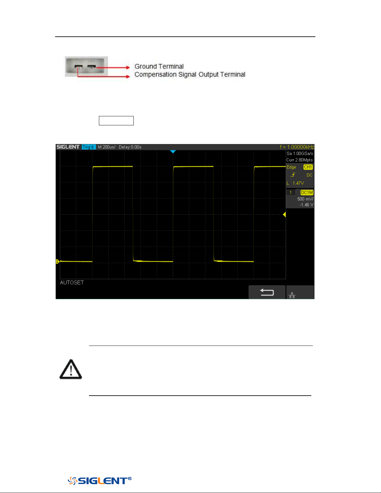
SDS1000X-E&SDS1000X-U User Manual
7
WWW.SIGLENT.COM
4-channel scope
3. Use the probe to connect the input terminal of CH1 of the oscilloscope and the
“Compensation Signal Output Terminal” of the probe.
4. Press the
Auto Setup.
5. Observe the waveform on the display. In normal condition, the display should
be a square waveform as shown in the figure below:
Figure 7 Function Inspection
6. Use the same method to test the other channels. If the square waveforms
actually shown do not match that in the figure above, please perform “Probe
Compensation”
in the next section.
WARNING
To avoid electric shock during the use of probe, please make sure that
the insulated wire of the probe is in good condition and do not touch the
metallic part of the probe when the probe is connected to high voltage
source
Probe Compensation
When the probes are used for the first time, you should compensate the probes to
match the input channels of the oscilloscope. Non-compensated or poorly
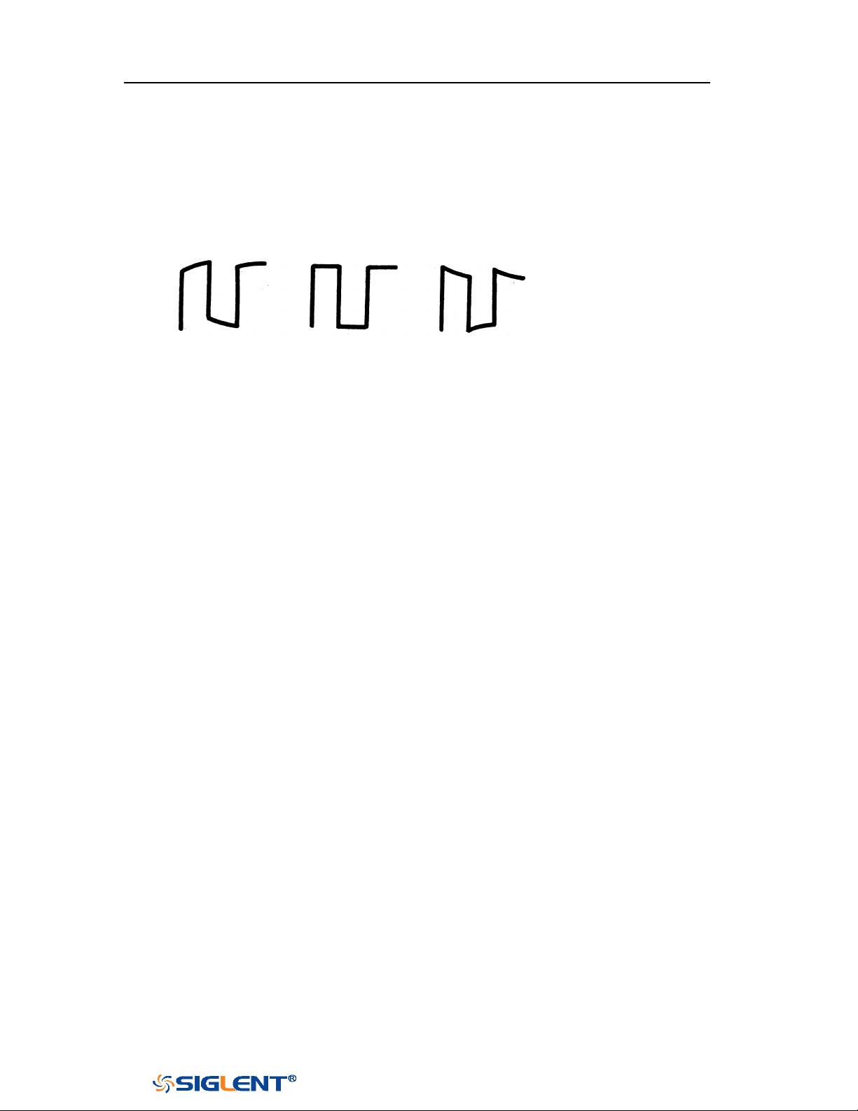
SDS1000X-E&SDS1000X-U User Manual
8
WWW.SIGLENT.COM
compensated probes may cause measurement inaccuracy or error. The probe
compensation procedures are as follows.
1. Set the switch to 10X on the probe.
2. Perform steps 1, 2, 3 and 4 of “Function Inspection” in the previous section.
3. Check the waveforms displayed and compare them with the following:
Under Perfectly Over
Compensated Compensated Compensated
4. Use a nonmetallic driver to adjust the low-frequency compensation adjustment
hole on the probe until the waveform displayed is as the “Perfectly
compensated” in the figure above.
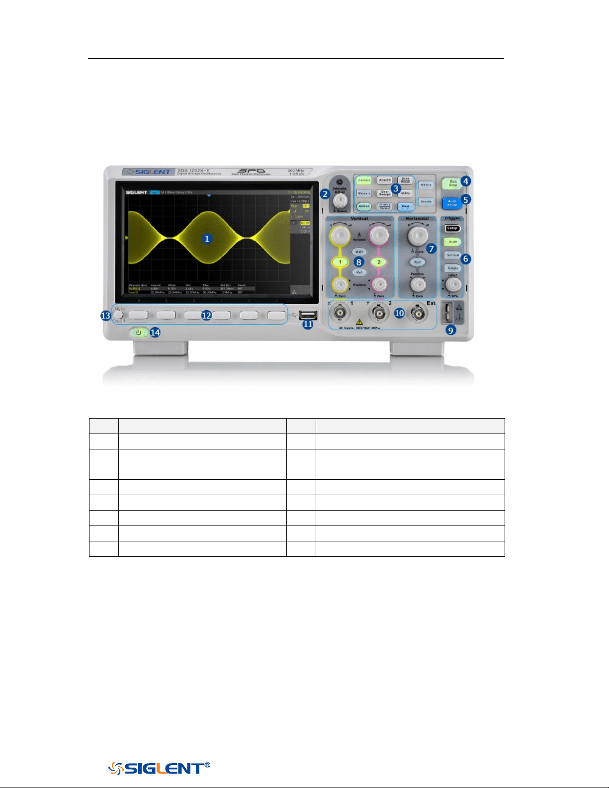
SDS1000X-E&SDS1000X-U User Manual
9
WWW.SIGLENT.COM
Front Panel Overview
Figure 8 SDS1000X-E 2-channel Scope Front Panel Overview
NO.
Description
NO.
Description
1
LCD Display
8
Vertical Control
2
Universal Knob
9
Probe Compensation/ Ground
Terminal
3
Common Function Menus
10
Analog Channel and Ext Input
4
Run/Stop
11
USB Host
5
Auto Setup
12
Menu Soft key
6
Trigger Control
13
Menu on/off
7
Horizontal Control
14
Power Button
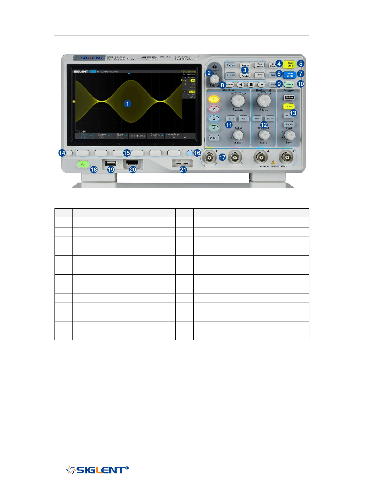
SDS1000X-E&SDS1000X-U User Manual
10
WWW.SIGLENT.COM
Figure 9 SDS1000X-E 4-Channel Scope Front Panel Overview
NO.
Description
NO.
Description
1
LCD Display
12
Horizontal Control
2
Universal Knob
13
Trigger Control
3
Common Function Menus
14
Menu on/off
4
Clear Sweeps
15
Menu Soft key
5
Run/Stop
16
One- Button shortcut for Save
6
Decode
17
Analog Channel
7
Auto Setup
18
Power Button
8
Navigate
19
USB Host
9
History
20
Digital Inputs
10
Default
21
Probe Compensation/ Ground
Terminal
11
Vertical Control, Math, REF and
Digital
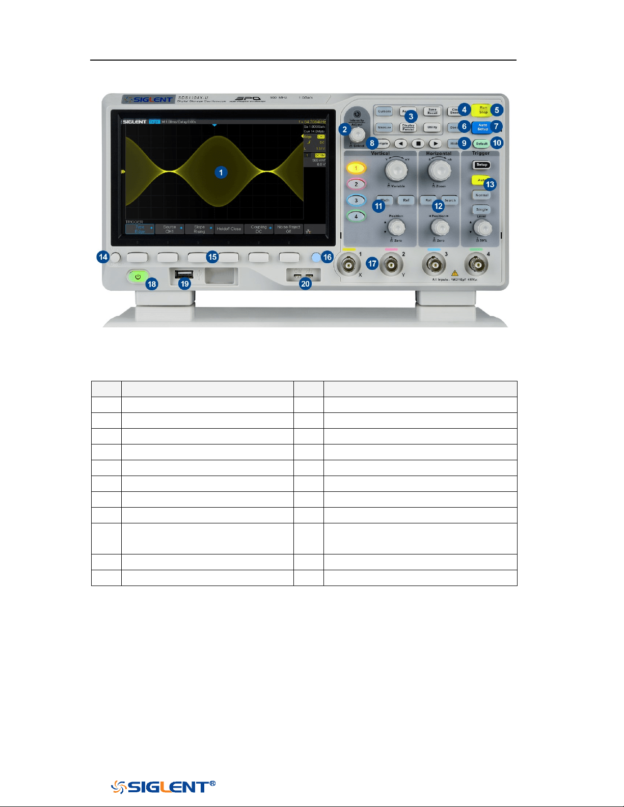
SDS1000X-E&SDS1000X-U User Manual
11
WWW.SIGLENT.COM
Figure 10 SDS1000X-U Scope Front Panel Overview
NO.
Description
NO.
Description
1
LCD Display
12
Horizontal Control
2
Universal Knob
13
Trigger Control
3
Common Function Menus
14
Menu on/off
4
Clear Sweeps
15
Menu Soft key
5
Run/Stop
16
One- Button shortcut for Save
6
Decode
17
Analog Channel
7
Auto Setup
18
Power Button
8
Navigate
19
USB Host
9
History
20
Probe Compensation/ Ground
Terminal
10
Default
11
Vertical Control, Math, REF
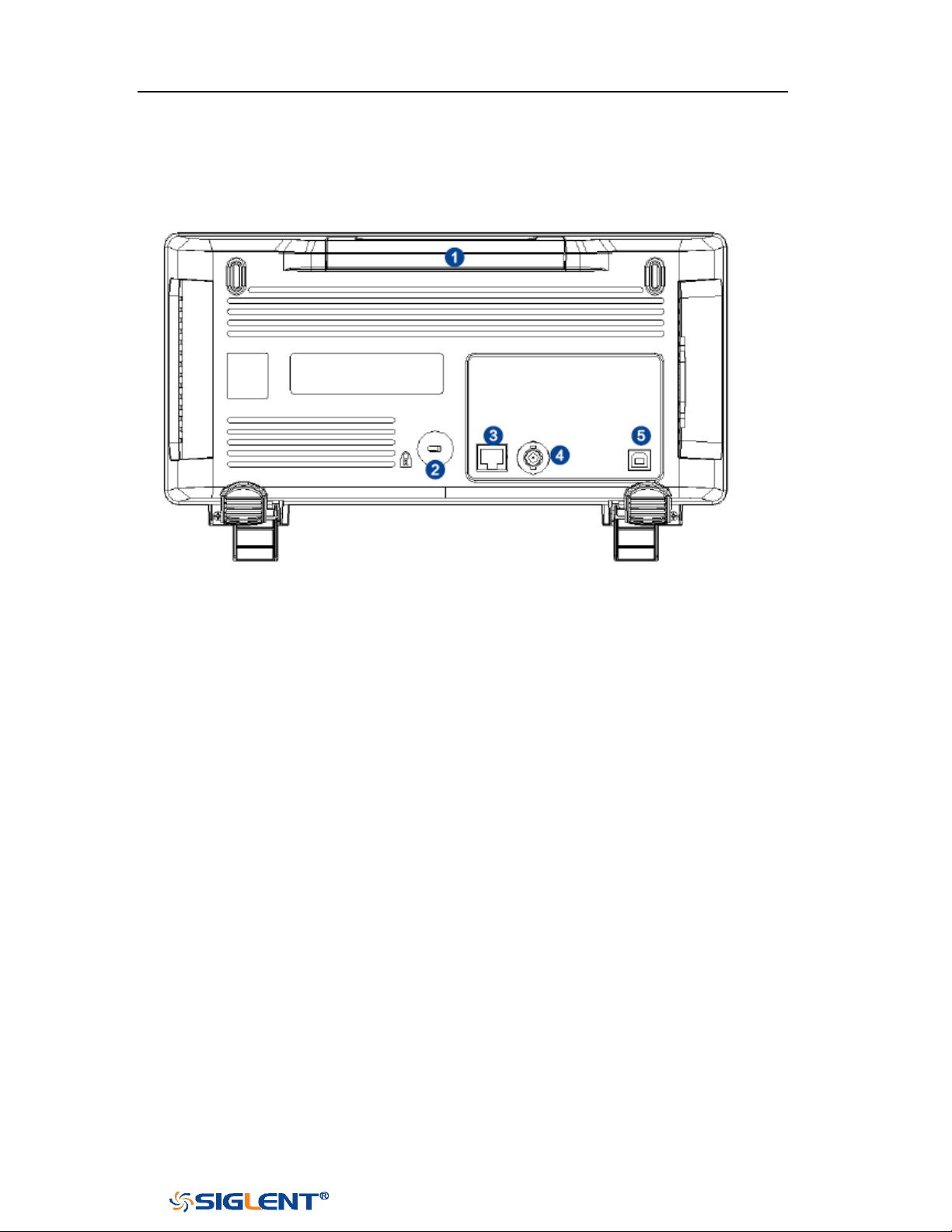
SDS1000X-E&SDS1000X-U User Manual
12
WWW.SIGLENT.COM
Rear Panel Overview
Figure 11 SDS1000X-E 2-Channel Scope Rear panel Overview
1. Handle
Pull up the handle vertically for easy carrying of the instrument. When you do
not need the handle, press it down.
2. Safety lock Hole
You can lock the instrument to a fixed location using the security lock (please
buy it yourself) via the lock hole.
3. LAN
The instrument can be connected to network via this interface to perform
remote control.
4. Pass/Fail or Trigger Out
The BNC port can output a signal that reflects the current waveform capture
rate of the oscilloscope at each trigger or a pass/fail test pulse.
5. USB Device
The oscilloscope support SCPI remote control commands, user can control the
oscilloscope through this interface.
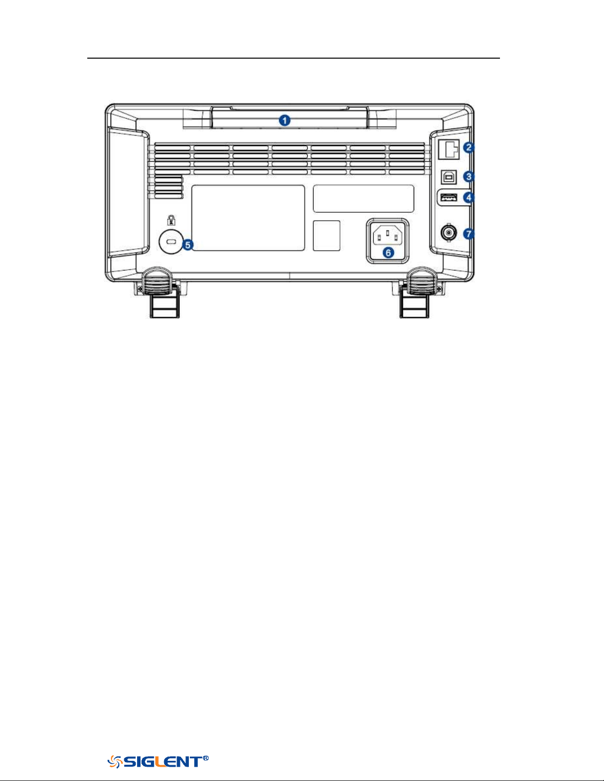
SDS1000X-E&SDS1000X-U User Manual
13
WWW.SIGLENT.COM
Figure 12 SDS1000X-E 4-channel Scope Rear panel Overview
1. Handle
Pull up the handle vertically for easy carrying of the instrument. When you do
not need the handle, press it down.
2. LAN
The instrument can be connected to network via this interface to perform
remote control.
3. USB Device
The oscilloscope support SCPI remote control commands, user can control the
oscilloscope through this interface
4. USB Host
Communicate with external function generators (SIGLENT SDG and SAG1021I)
5. Safety lock Hole
You can lock the instrument to a fixed location using the security lock (please
buy it yourself) via the lock hole.
6. AC Power Socket
AC power input terminal. The power requirements of this oscilloscope are
100-240 V, 50/60/400 Hz. Use the power cord provided with the instrument to
connect it to AC power.
7. Pass/Fail or Trigger Out
The BNC port can output a signal that reflects the current waveform capture
rate of the oscilloscope at each trigger or a pass/fail test pulse.
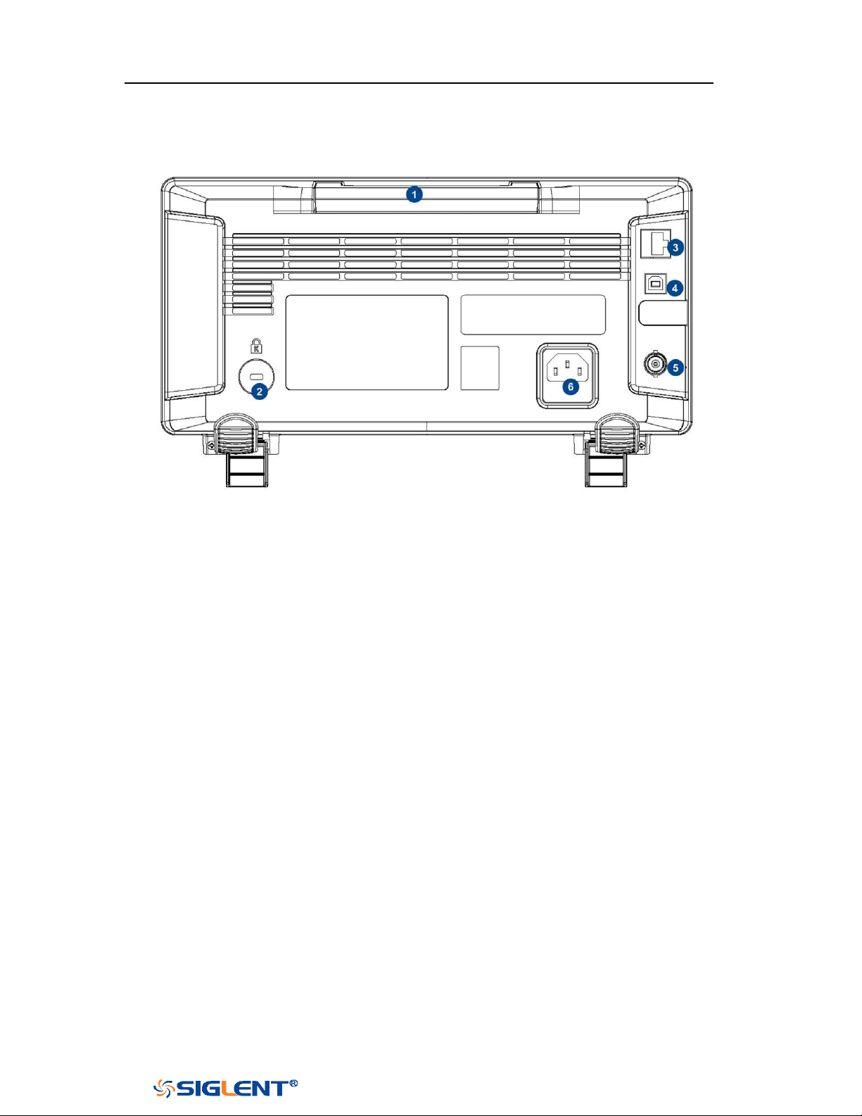
SDS1000X-E&SDS1000X-U User Manual
14
WWW.SIGLENT.COM
Figure 13 SDS1000X-U Scope Rear panel Overview
1. Handle
Pull up the handle vertically for easy carrying of the instrument. When you do
not need the handle, press it down.
2. Safety lock Hole
You can lock the instrument to a fixed location using the security lock (please
buy it yourself) via the lock hole.
3. LAN
The instrument can be connected to network via this interface to perform
remote control.
4. USB Device
The oscilloscope support SCPI remote control commands, user can control the
oscilloscope through this interface
5. Pass/Fail or Trigger Out
The BNC port can output a signal that reflects the current waveform capture
rate of the oscilloscope at each trigger or a pass/fail test pulse.
6. AC Power Socket
AC power input terminal. The power requirements of this oscilloscope are
100-240 V, 50/60/400 Hz. Use the power cord provided with the instrument to
connect it to AC power.
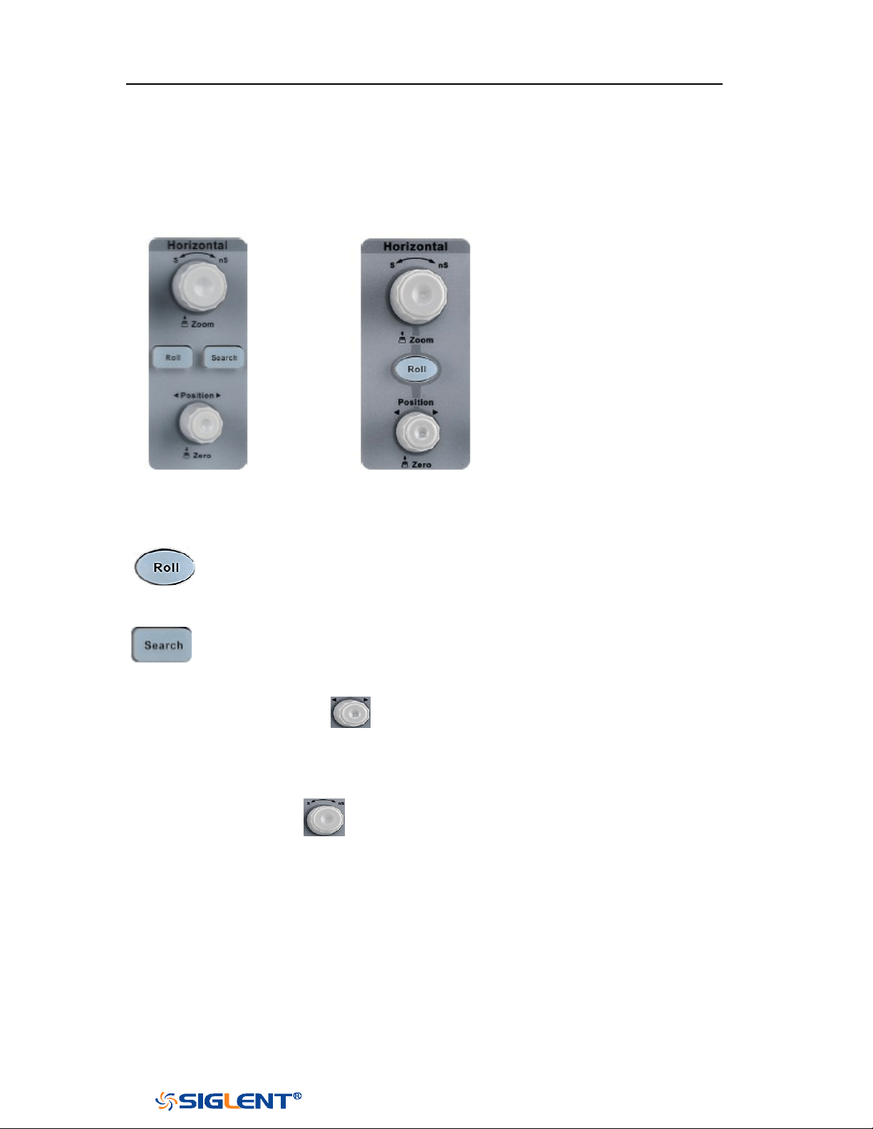
SDS1000X-E&SDS1000X-U User Manual
15
WWW.SIGLENT.COM
Front Panel Function Overview
Horizontal
4-channel scope 2-channel scope
: Quickly enter the roll mode. The timebase range is from 50mS/div to
100S/div.
: Enable or disable search function. This function can search for the
events that users specify in the acquired data, the results are displayed
with white triangle symbol.
Horizontal Position Knob : adjust horizontal position. Turn the knob to
change the horizontal delay time, waveforms of all channels will move horizontally
with the trigger point. Press down this knob to quickly reset the horizontal delay to
Zero.
Horizontal Scale Knob : adjust the horizontal time base. Turn clockwise to
reduce the time base and turn counterclockwise to increase the time base. During
the modification, waveforms of all the channels will be displayed in expanded or
compressed mode and the time base message at the upper-left side of the screen
would change accordingly. Press down this knob to quickly turn on Zoom function.
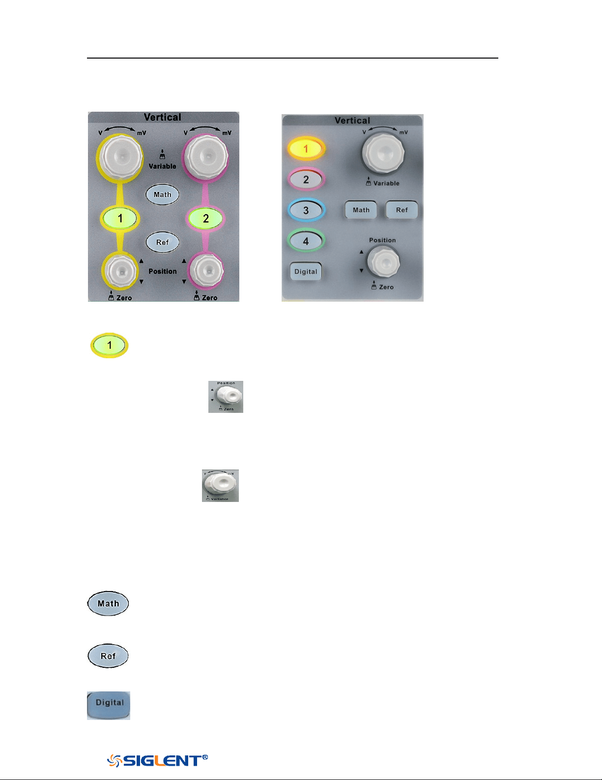
SDS1000X-E&SDS1000X-U User Manual
16
WWW.SIGLENT.COM
Vertical
2-channel scope 4-channel scope
: Analog input channels. The two channels are marked by different colors
which are also used to mark both the corresponding waveforms on the
screen and the channel input connectors.
Vertical Position Knob : adjust the vertical position of the current channel
waveform. Turn clockwise to increase the position and turn counterclockwise to
decrease. During the modification, the waveform would move up and down and
the position message at the lower-left corner of the screen would change
accordingly. Press down this knob to quickly reset the vertical position to zero.
Vertical Variable Knob : adjust the vertical scale of the current channel.
Turn clockwise to decrease the scale and turn counterclockwise to increase. During
the modification, the amplitude of the waveform would enlarge or reduce and the
scale information at the right side of the screen would change accordingly. Press
down this knob to quickly switch the vertical scale adjustment modes between
“Coarse” and “Fine”.
: press the button to enter the MATH function menu. The oscilloscope
provides addition, subtraction, multiplication, FFT, differential, integral
and square root operations.
: press the button to enter the REF function menu. A reference waveform
can be displayed and compared against other waveforms.
: Press the button to open the digital channel function menu (Optional
function). The SDS1000X-E (4-channel scope) supports 16 digital channels.
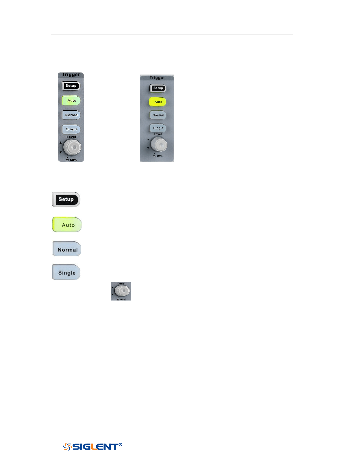
SDS1000X-E&SDS1000X-U User Manual
17
WWW.SIGLENT.COM
Trigger
2-channel scope 4-channel scope
: press the button to enter the TRIGGER function menu. The oscilloscope
provides abundant advanced trigger functions
: press the button to set the trigger mode to Auto.
: press the button to set the trigger mode to Normal.
: press the button to set the trigger mode to Single.
Trigger Level Knob : adjust the trigger level. Turn clockwise to increase the
level and turn counterclockwise to reduce the level. During the modification, the
trigger level line would move up and down and the value in the trigger level
message box at the up-right corner of the screen would change accordingly. Press
down the knob to quickly reset the trigger level to center of the waveform.
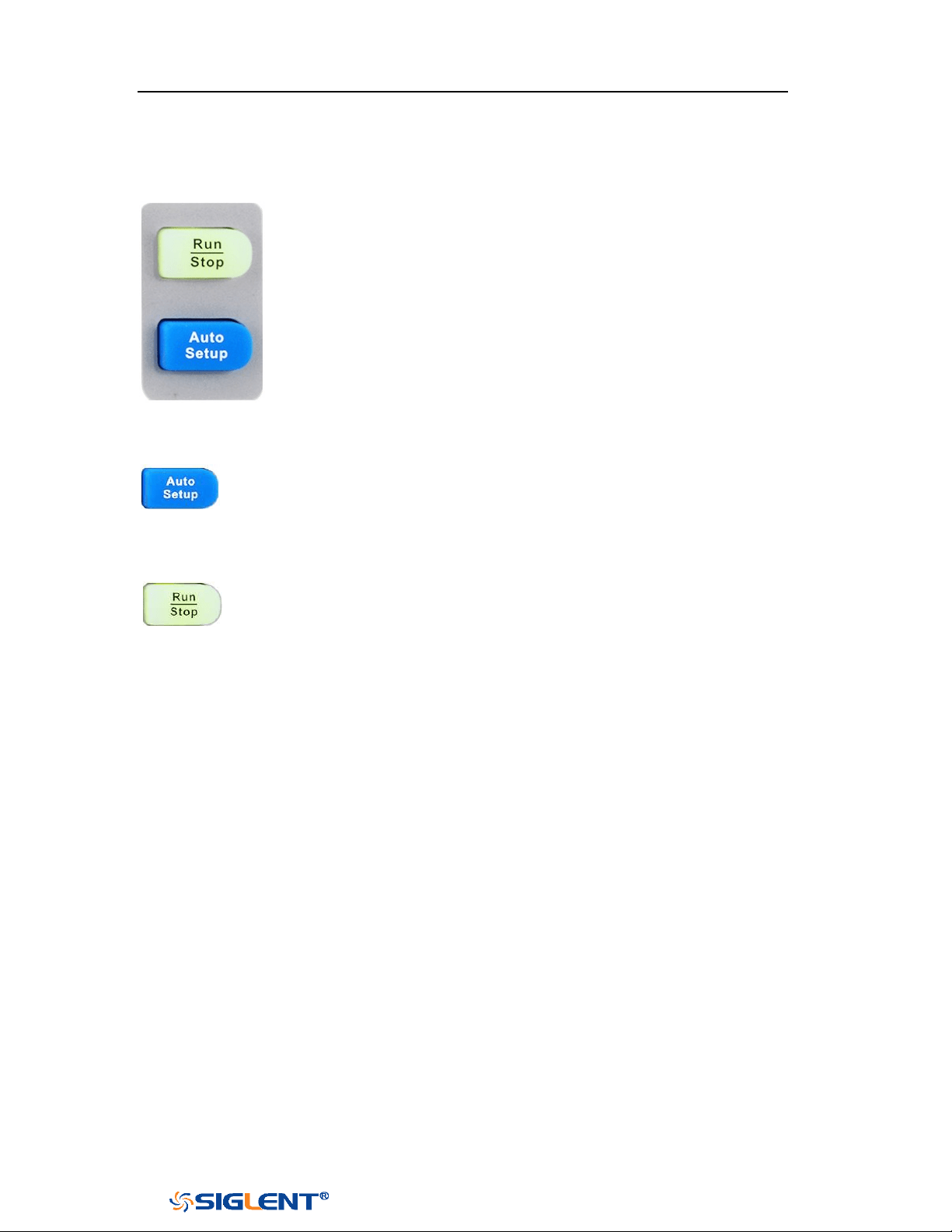
SDS1000X-E&SDS1000X-U User Manual
18
WWW.SIGLENT.COM
Run Control
: press this key to enable the waveform auto setting function. The
oscilloscope will automatically adjust the vertical scale, horizontal time
base and trigger mode according to the input signal to realize optimum
waveform display.
: press the button to set the acquisition state to Run or Stop.
In RUN state, the key is illuminated in yellow.
In STOP state, the key is illuminated in red.
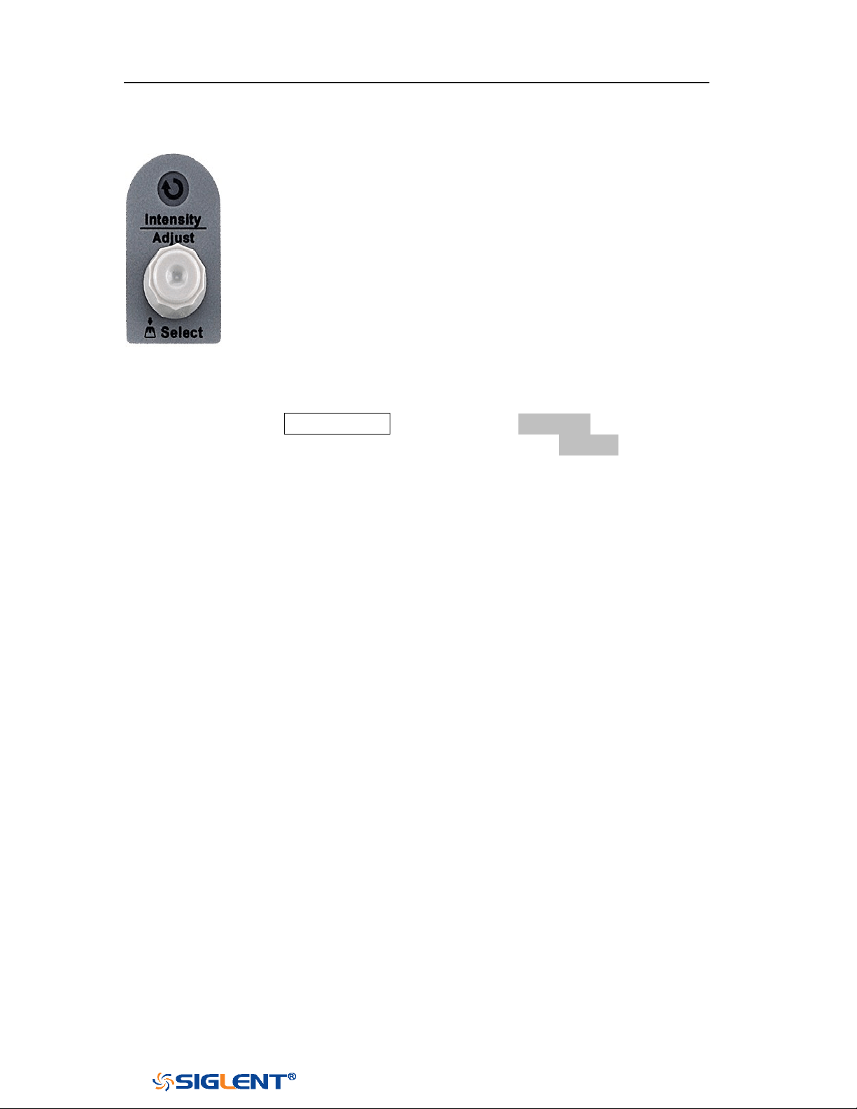
SDS1000X-E&SDS1000X-U User Manual
19
WWW.SIGLENT.COM
Universal Knob
1. Adjust the waveform intensity.
You can press the Display/Persist button; press the Next Page soft key to go to
the second page of the DISPLAY function menu; press the Intensity soft key and
then turn the Universal Knob to adjust the waveform intensity.
2. Select the desired submenu.
In menu operation, press any menu soft key and turn the Universal Knob to
select the desired submenu under the menu and push down the knob to
confirm the current submenu. Turn clockwise to up the intensity and
counterclockwise to down.
3. Modify parameters.
After having chosen a parameter, turn the Universal Knob to modify the value.
Turn clockwise to increase the intensity and counterclockwise to reduce. In
addition, it can also be used to adjust scale and offset of MATH and REF.
4. Choose file or directory or input filename.
After having entered the file system, turn the Universal Knob to select the
desired file or directory. When inputting filename, turn the Universal Knob to
select the desired character and the push the knob to confirm.
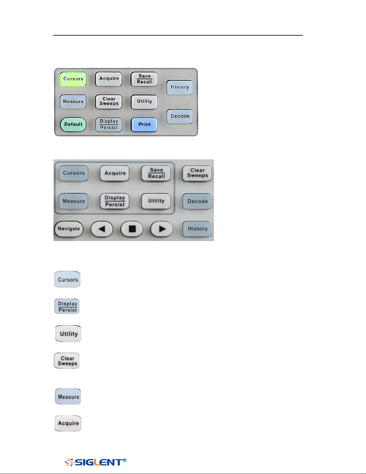
SDS1000X-E&SDS1000X-U User Manual
20
WWW.SIGLENT.COM
Menu
2-channel scope common function panel
4-channel scope common function panel
: Press to enter the CURSOR function menu. The oscilloscope provides
manual and track cursor mode.
: Press to enter the DISPLAY function menu and quickly enable the persist
function. User can set the grid, intensity, graticule, and transparence.
: Press to enter the UTILITY function menu to look at the system status, do
self-calibration, set the sound, language and so on.
: The button is a shortcut key for clear function. When the measurement
statistics is ON, press the button to clear the count and recount it. When
persist is enabled, press the button to clear persist.
: Press the button to enter the MEASURE function menu to set the
measurement parameters, all measurement, statistics and gate.
: Press the button to enter the ACQUIRE function menu to set the
acquisition mode, memory depth, wave interpolation and so on.

SDS1000X-E&SDS1000X-U User Manual
21
WWW.SIGLENT.COM
: Press the button to enter the SAVE/RECALL function menu to save
setups, waveforms, pictures, or CSV files, binary data, matlab files, and
default key presets to internal memory or USB flash driver.
: Press the button to reset the oscilloscope to user default setup.
: Press the button to enter the history mode. In history mode, it can
record most 80000 frames waveforms. If sequence function is enabled, it
only record the frames which you set, the most you can set is 80000.
: Press the button to enter the DECODE function menu. The oscilloscope
supports I2C, SPI, UART, CAN and LIN serial bus decode.
: Press the button to turn off or turn on the navigate function.
SDS1000X-E (4-channel scope) and SDS1000X-U support three navigate
types: time, search event, history frame.
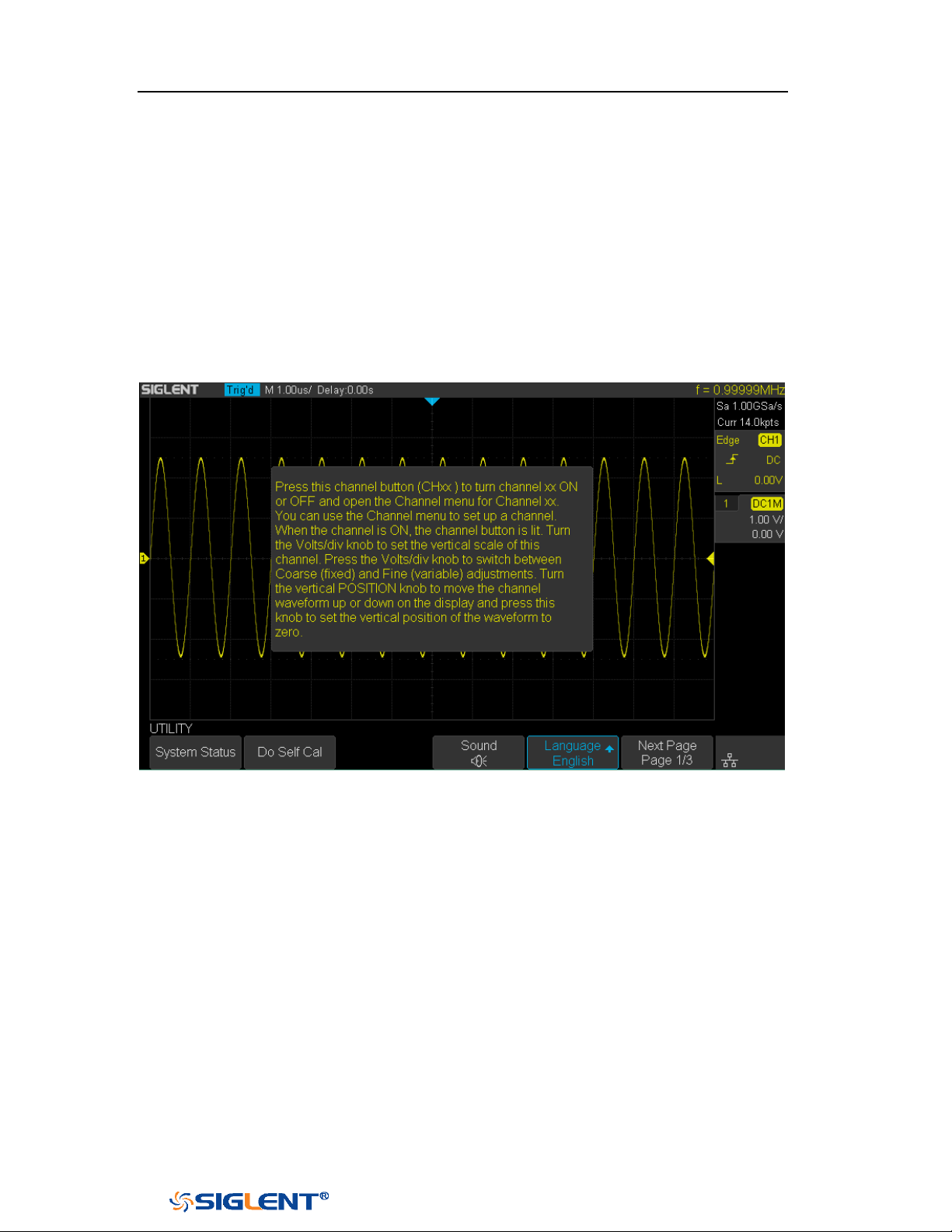
SDS1000X-E&SDS1000X-U User Manual
22
WWW.SIGLENT.COM
Help
The oscilloscope has an on line help function that supplies multi-language help
information.
You can access the help function by pressing any button for 2 seconds and a help
window will explain the function. Also all of the submenus include help
information.
Figure 14 Help Message
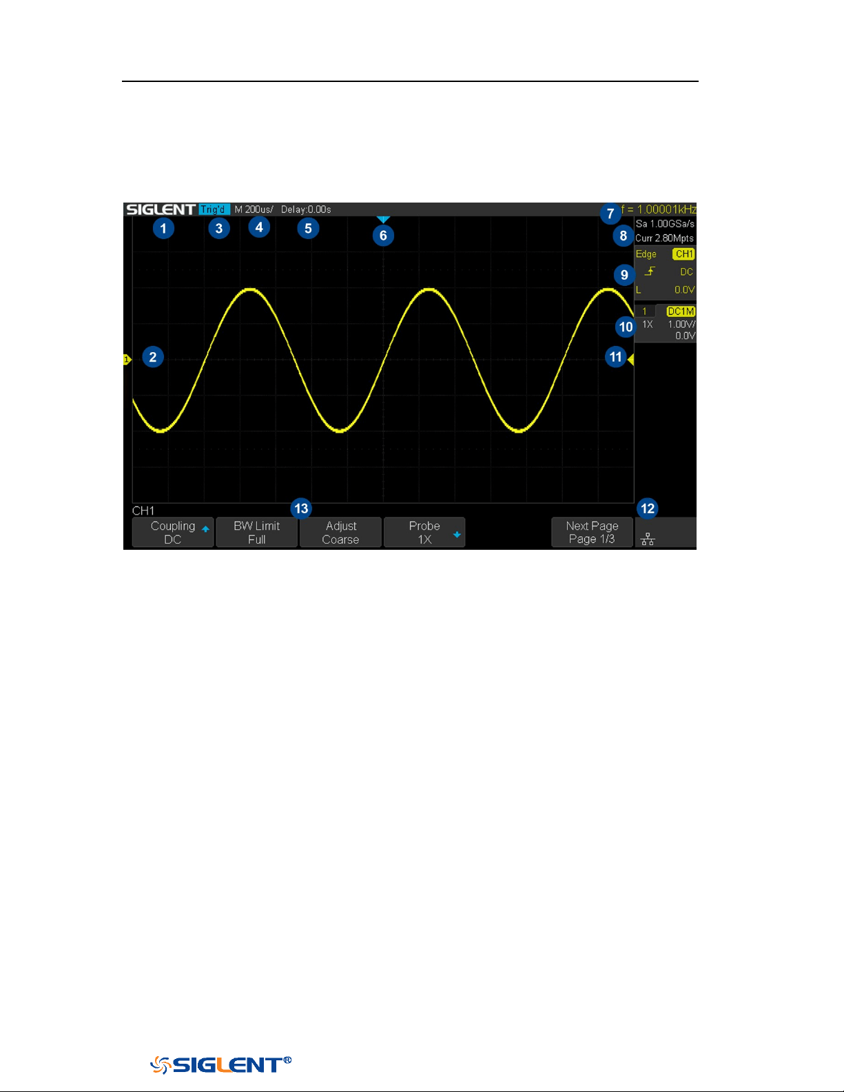
SDS1000X-E&SDS1000X-U User Manual
23
WWW.SIGLENT.COM
User Interface
Figure 15 User Interface
1. Product Logo
SIGLENT is the registered trademark of SIGLENT TECHNOLOGIES CO., LTD.
2. Channel Label/Waveform
Different channels are marked by different colors and the color of the
waveform complies with the color of the channel.
3. Trigger Status
Available trigger status includes Ready, Auto, Stop, Arm, Trig’d, FStop.
4. Horizontal Time Base
Represent the time per grid on the horizontal axis on the screen.
Use the
HORIZONTAL SCALE Knob to adjust the parameter. The available
range is from 1.0 ns to 100 s for SDS1000X-E; while from 2.0 ns to 100s for
SDS1000X-U.
5. Horizontal Position (Delay)
Turn the Horizontal Position Knob to adjust the parameter. Push the knob to set
the value to 0 automatically.
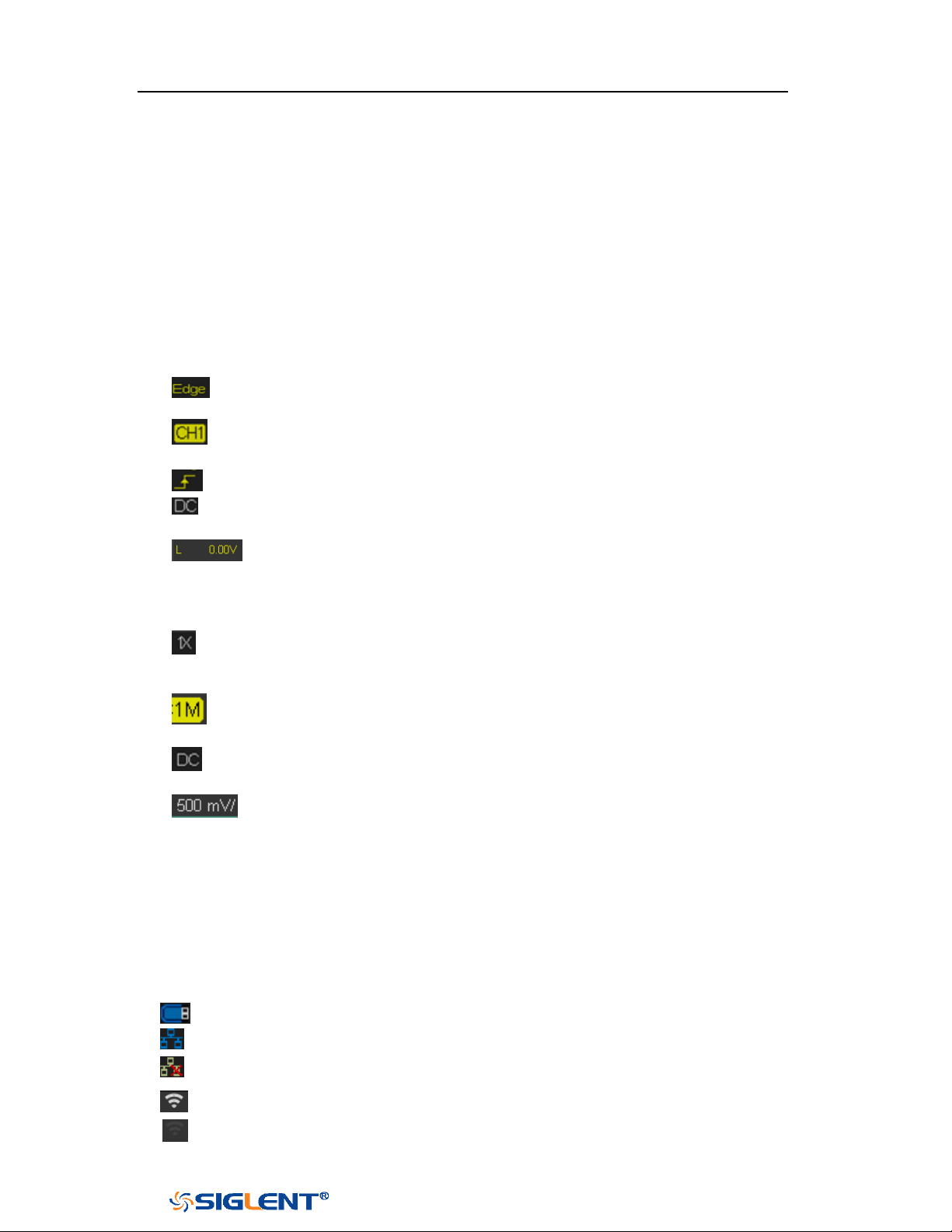
SDS1000X-E&SDS1000X-U User Manual
24
WWW.SIGLENT.COM
6. Trigger Delay Label
Indicate the trigger delay on the waveform.
7. Frequency Counter
Display the frequency value of the trigger channel.
8. Sampling Rate/ Memory Depth
Display the current sampling rate and memory depth. Sa means the current
sampling rate and Curr means the current memory depth.
9. Trigger Setup
Trigger Type: display the current trigger type. The trigger type names
display by the abbreviation when the name is too long to display.
Trigger source: display the currently trigger source. Different channels
display in different color.
Trigger condition: display the current trigger condition.
Trigger coupling: display the current trigger coupling. Available trigger
coupling mode: DC, AC, HF Reject, LF Reject.
Trigger level: display the current value of trigger level. Push the knob
to set the trigger to the 50% of the waveform amplitude automatically.
10. Channel Setup
Probe attenuation factor: display the current probe attenuation factor of
the channel. Available probe attenuation factors: 0.1X, 0.2X, 0.5X,
1X …properties 2000X, 5000X, 10000X.
Input impedance: display the current input impedance of the channel.
Input impedance that available: 1MΩ.
Channel coupling: display the current channel coupling of the channel.
Channel coupling that available: DC, AC, and GND.
Vertical Scale: display the current vertical scale of the channel. Turn
the Vertical Scale Knob to adjust the value.
11. Trigger Level Label
Display the position of trigger level, the color is the same to the trigger channel.
It can move from +4.5div to -4.5div of the screen center.
12. I/O status
Indicate that the USB Host is connected.
Indicate that the LAN port is connected.
Indicate that the LAN port is disconnected.
Indicate that the WLAN port is connected.
Indicate that the WLAN port is disconnected.

SDS1000X-E&SDS1000X-U User Manual
25
WWW.SIGLENT.COM
13. Menu
Display the corresponding function menu of the selected button. Press the
corresponding soft key to set the oscilloscope.
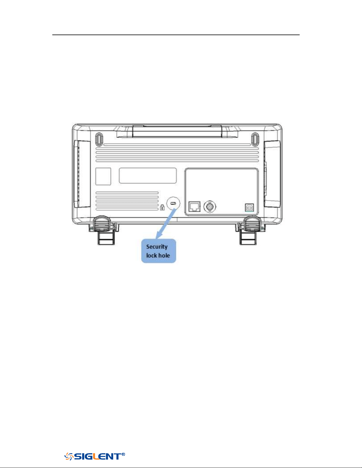
SDS1000X-E&SDS1000X-U User Manual
26
WWW.SIGLENT.COM
Security Lock
If needed, you can use the security lock (please buy it yourself) to lock the
oscilloscope to a fixed location. The method is as follows, align the lock with the
lock hole and plug it into the lock hole vertically, turn the key clockwise to lock the
oscilloscope and then pull the key out.
Figure 16 to Use the Security Lock

SDS1000X-E&SDS1000X-U User Manual
27
WWW.SIGLENT.COM
Vertical System
This chapter introduces how to set the vertical system of the oscilloscope.
The contents of this chapter:
Enable the Channel
Adjust Scale
Vertical Position
Coupling
Bandwidth Limit
Probe
Unit
Deskew
Invert
Trace Visible/Hidden
Label

SDS1000X-E&SDS1000X-U User Manual
28
WWW.SIGLENT.COM
Enable the Channel
The oscilloscope provides 2/4 analog input channels and provides independent
vertical control system for each channel. As the vertical system setting methods of
every channel is the same, this chapter takes CH1 as an example to introduce the
setting method of the vertical system.
Connect a signal to the CH1 channel connector; and then press the
CH1 button in
the vertical control area (VERTICAL) at the front panel to enable CH1.
The channel setting menu is displayed at the bottom of the screen and the channel
label at the right side of the screen. The information displayed in the channel label
is related to the current channel setting.
After the channel is turned on, modify the parameters such as the vertical scale, the
horizontal time base and the trigger mode according to the input signal to make
the waveform display easy to observe and measure.
Note: to turn off the channel, press the channel button twice.

SDS1000X-E&SDS1000X-U User Manual
29
WWW.SIGLENT.COM
Note: push the VERTICAL Variable Knob to quickly switch between Coarse and
Fine adjustments.
Adjust Scale
The vertical scale can be adjusted in
Coarse or Fine mode.
Coarse adjustment (take counterclockwise as an example): set the vertical
scale in 1-2-5 step namely 500uV/div, 1 mV/div, 2 mV/div, 5 mV/div, 10
mV/div …10 V/div.
Fine adjustment: further adjust the vertical scale within a relatively smaller
range to improve vertical resolution. For example: 2 V/div, 1.98V/div,
1.96V/div, 1.94 V/div …1 V/div.
If the amplitude of the input waveform is a little bit greater than the full scale
under the current scale and the amplitude would be a little bit lower if the next
scale is used, fine adjustment can be used to improve the amplitude of
waveform display to view signal details.
Press the
CH1 button on the front panel; then press the Adjust soft key to select the
desired mode. Turn the VERTICAL Variable Knob to adjust the vertical scale
(clockwise to reduce the scale and counterclockwise to increase).
The scale information in the channel label at the right side of the screen will
change accordingly during the adjustment. The adjustable range of the vertical
scale is related to the probe ratio currently set. By default, the probe attenuation
factor is 1X and the adjustable range of the vertical scale is from 500uV/div to 10
V/div.

SDS1000X-E&SDS1000X-U User Manual
30
WWW.SIGLENT.COM
Vertical Position
Turn the
VERTICAL Position Knob to adjust the vertical position of the channel
waveform. Turn the knob clockwise to increase the vertical position and the
channel waveform moves up while counterclockwise to reduce the vertical position
and the waveform moves down. Push the knob to set the vertical position of the
channel waveform to zero.
During the adjustment, the vertical position information Volts Pos displays at the
bottom of the screen. The table below shows the range of vertical position
according to the volt scale.
Oscilloscope
Volt Scale
Range of Vertical Position
SDS1000X-E
500 μV/div ~ 100 mV/div
±2V
102 mV/div ~ 1 V/div
±20 V
1.02 V/div ~ 10 V/div
±200 V
SDS1000X-U
1mV/div ~ 200 mV/div
±2 V
206 mV/div ~ 10 V/div
±100 V
Coupling
Set the coupling mode to filter out the undesired signals. For example, the signal
under test is a square waveform with DC offset.
When the coupling mode set to
DC: the DC and AC components of the signal
under test can both pass the channel.
When the coupling mode set to AC: the DC components of the signal under test
are blocked.
When the coupling mode set to GND: the DC and AC components of the signal
under test are both blocked.
Press the CH1 button on the front panel; then press the Coupling softkey and turn
the Universal Knob to select the desired coupling mode. The default setup is DC.
The current coupling mode is displayed in the channel label at the right side of the
screen. You can also press the Coupling softkey continuously to switch the coupling
mode.
SDS1000X-E&SDS1000X-U User Manual
31
WWW.SIGLENT.COM
Bandwidth Limit
Set the bandwidth limit to reduce display noise. For example, the signal under test
is a pulse with high frequency oscillation.
When the bandwidth limit set to
Full, the high frequency components of the
signal under test can pass the channel.
When the bandwidth limit set to 20M, the high frequency components that
exceed 20 MHz are attenuated.
Press the CH1 button on the front panel; then press the BW Limit softkey to select
Full or 20M. The default setup is Full. When bandwidth limit is enabled, the
character B will be displayed in the channel label at the right side of the screen.
Probe
Set the probe attenuation factor to match the type of the probe that you are using
to ensure correct vertical readouts.
Press the CH1 button on the front panel; then press the Probe softkey and turn the
Universal Knob to select the desired value and push the knob to confirm. The
default setup is 1X.
The current probe attenuation factor is displayed in the channel label at the right
side of the screen. You can also press the Probe softkey continuously to switch the
probe attenuation factor.
The table shows the probe attenuation factor
Menu
Attenuation Factor
0.1X
0.1 : 1
0.2X
0.2 : 1
0.5X
0.5 : 1
1X
1 : 1
2X
2 : 1
…
…
5000X
5000 : 1
10000X
10000 : 1
Custom
1000000:1~0.000001:1
SDS1000X-E&SDS1000X-U User Manual
32
WWW.SIGLENT.COM
You can also customize the probe attenuation factor. Press the Probe softkey,
select Custom, and then press the Custom softkey to select Custom or Custom Fine.
First, select Custom and turn the Universal Knob to achieve rough adjustment; and
then select Custom Fine and turn the Universal Knob to achieve fine adjustment.
Unit
Select the amplitude display unit for the current channel. The available units are
V
and
A. When the unit is changed, the unit displayed in the channel label will
change accordingly.
1. Press CH1button on the front panel to enter the CH1 function menu.
2. Press the Next Page softkey to enter the second page of the CH1 function
menu.
3. Press the Unit softkey to select the desired unit V or A.
The default setup is V.
Deskew
The valid range of each analog channel is ±100ns.
1. Press
CH1button on the front panel to enter the CH1 function menu.
2. Press the Next Page softkey to enter the second page of the CH1 function
menu.
3. Press the Deskew softkey. Then turn the Universal Knob to change deskew.
Invert
When Invert is set to On, the voltage values of the displayed waveform are inverted.
Invert affects how a channel is displayed and it keeps the trigger settings.
Inverting a channel also changes the result of any math function selected and
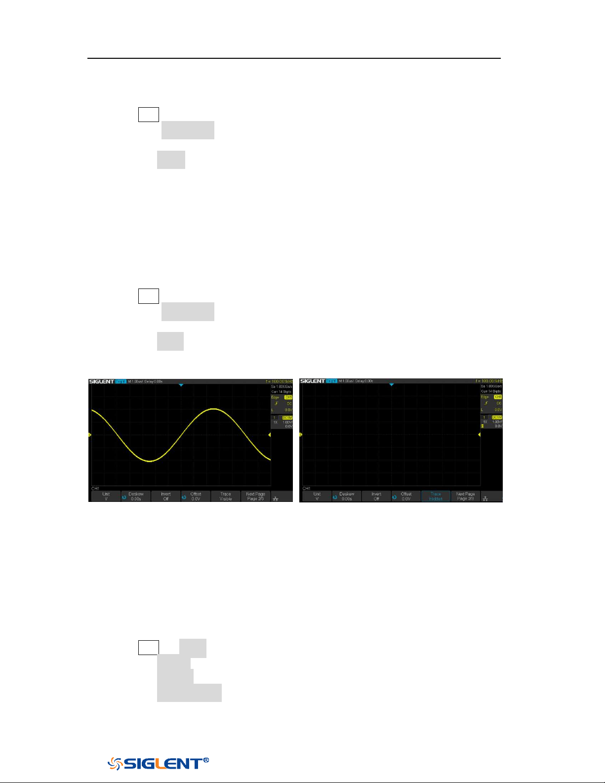
SDS1000X-E&SDS1000X-U User Manual
33
WWW.SIGLENT.COM
measure function.
1. Press CH1button on the front panel to enter the CH1 function menu.
2. Press the Next Page softkey to enter the second page of the CH1 function
menu.
3. Press the Invert softkey to turn on or off the invert display.
Trace Visible/Hidden
Set whether the current channel waveform is visible.
1. Press
CH1 button on the front panel to enter the CH1 function menu.
2. Press the Next Page softkey to enter the second page of the CH1 function
menu.
3. Press the Trace softkey to visible or hidden the channel waveform
Trace Visible
Trace Hidden
Label
SDS1000X-E (4-channel) supports setting label text for channels.
1 Press CH1 → Label to enter the LABEL function menu.
2 Press the Source softkey to select the source.
3 Press the Display softkey to turn on or off the label for the current channel.
4 Press the Label Setting softkey to enter the Text Input function menu. The
length of the label is limited to 20 characters. The characters beyond this
length will not be displayed. When the “Display” option is set to “on”, the
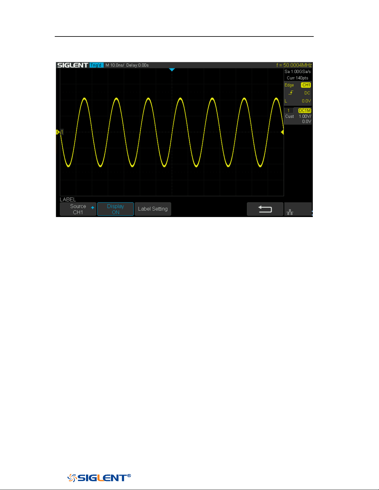
SDS1000X-E&SDS1000X-U User Manual
34
WWW.SIGLENT.COM
label will be displayed on the right side of the channel offset indicator.
Figure 17 CH1 Label Display

SDS1000X-E&SDS1000X-U User Manual
35
WWW.SIGLENT.COM
Horizontal System
This chapter introduces how to set the horizontal system of the oscilloscope.
The contents of this chapter:
Horizontal Scale
Horizontal Delay
Roll Mode
Zoom Mode

SDS1000X-E&SDS1000X-U User Manual
36
WWW.SIGLENT.COM
Horizontal Scale
Turn the
HORIZONTAL Scale Knob on the front panel to adjust the horizontal time
base. Turn clockwise to reduce the horizontal time base and turn counterclockwise
to increase.
The time base information at the upper left corner of the screen will change
accordingly during the adjustment. The range of the SDS1000X-E horizontal scale is
from 1ns/div to 100s/div. The range of the SDS1000X-U horizontal scale is from
2ns/div to 100s/div.
The
Horizontal Scale Knob works (in the Normal time mode) while acquisitions are
running or when they are stopped. When in run mode, adjusting the horizontal
scale knob changes the sample rate. When stopped, adjusting the horizontal scale
knob lets you zoom into acquired data.

SDS1000X-E&SDS1000X-U User Manual
37
WWW.SIGLENT.COM
Horizontal Delay
Turn the
Horizontal Position Knob on the front panel, the trigger point (solid
inverted triangle) will move horizontally. The trigger point moves horizontally to
the right when it rotates clockwise, while moves to left when it rotates
counter-clockwise. Press down this knob to quickly reset the trigger delay.
When changing the horizontal delay, the delay time displayed in the information
bar at the top of the screen changes in real time, indicating the distance between
the time reference point and the trigger point. The amount of delay range available
depends on the time/div selected and memory depth.

SDS1000X-E&SDS1000X-U User Manual
38
WWW.SIGLENT.COM
Roll Mode
Press the
Roll button to enter the roll mode.
In Roll mode the waveform moves slowly across the screen from right to left. It only
operates on time base settings of 50 ms/div and slower. If the current time base
setting is faster than the 50 ms/div limit, it will be set to 50 ms/div when Roll mode
is entered.
In Roll mode there is no trigger. The fixed reference point on the screen is the right
edge of the screen and refers to the current moment in time. Events that have
occurred are scrolled to the left of the reference point. Since there is no trigger, no
pre- trigger information is available.
If you would like to stop the display in Roll mode, press the
Run/Stop button. To
clear the display and restart an acquisition in Roll mode, press the Run/Stop button
again.
Use Roll mode on low- frequency waveforms to yield a display much like a strip
chart recorder. It allows the waveform to roll across the display.
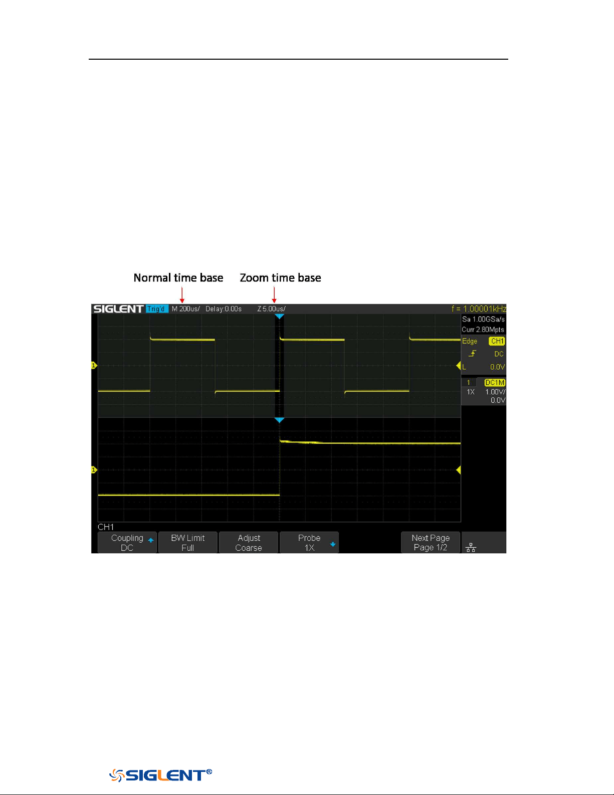
SDS1000X-E&SDS1000X-U User Manual
39
WWW.SIGLENT.COM
Zoom Mode
Zoom is a horizontally expanded version of the normal display. You can use Zoom
to locate and horizontally expand part of the normal window for a more detailed
(higher- resolution) analysis of signals.
Press the
HORIZONTAL Scale Knob on the front panel to turn on the zoom function,
and press the button again to turn off the function. When Zoom function is on, the
display divides in half. The top half of the display shows the normal time base
window and the bottom half displays a faster Zoom time base window.
Figure 18 Split Screen Zoom
The area of the normal display that is expanded is outlined with a box and the rest
of the normal display is ghosted. The box shows the portion of the normal sweep
that is expanded in the lower half.
To change the time base for the Zoom window, turn the
Horizontal Scale Knob. The
Horizontal Scale Knob controls the size of the box. The Horizontal Position Knob
sets the left- to- right position of the zoom window. The delay value, which is the
time displayed relative to the trigger point is momentarily displayed in the upper-
right corner of the display when the Horizontal Position Knob is turned. Negative
delay values indicate you're looking at a portion of the waveform before the trigger

SDS1000X-E&SDS1000X-U User Manual
40
WWW.SIGLENT.COM
event, and positive values indicate you're looking at the waveform after the trigger
event.
To change the time base of the normal window, turn off Zoom; then, turn the
Horizontal Scale Knob.

SDS1000X-E&SDS1000X-U User Manual
41
WWW.SIGLENT.COM
Sample System
This chapter introduces how to use the run control and set the sampling system of
the oscilloscope.
The contents of this chapter:
Run Control
Overview
Memory Depth
Sampling Mode
Interpolation Method
Acquisition Mode
Horizontal Format
Sequence Mode

SDS1000X-E&SDS1000X-U User Manual
42
WWW.SIGLENT.COM
Run Control
Press the
Run/Stop or Single button on the front panel to run or stop the sampling
system of the scope.
When the Run/Stop button is green, the oscilloscope is running, that is,
acquiring data when trigger conditions are met. To stop acquiring data, press
the Run/Stop button. When stopped, the last acquired waveform is
displayed.
When the Run/Stop button is red, data acquisition is stopped. Red "Stop" is
displayed next to the trademark logo in the status line at the top of the display.
To start acquiring data, press
Run/Stop.
To capture and display a single acquisition (whether the oscilloscope is
running or stopped), press Single. The Single run control lets you view single-
shot events without subsequent waveform data overwriting the display. Use
Single when you want maximum memory depth for pan and zoom.
When you press
Single, the display is cleared, the trigger mode is temporarily set to
Normal (to keep the oscilloscope from auto- triggering immediately), the trigger
circuitry is armed, the Single key is illuminated, and the oscilloscope waits until a
user defined trigger condition occurs before it displays a waveform.
When the oscilloscope triggers, the single acquisition is displayed and the
oscilloscope is stopped (the
Run/Stop button is illuminated in red).
Press Single again to acquire another waveform.

SDS1000X-E&SDS1000X-U User Manual
43
WWW.SIGLENT.COM
Overview
To understand the oscilloscope's sampling and acquisition modes, it is helpful to
understand sampling theory, sample rate and oscilloscope bandwidth and sample
rate.
Sampling Theory
The Nyquist sampling theorem states that for a limited bandwidth (band- limited)
signal with maximum frequency f
MAX
, the equally spaced sampling frequency f
S
must be greater than twice the maximum frequency f
MAX
, in order to have the signal
be uniquely reconstructed without aliasing.
f
MAX
= f
S/2
= Nyquist frequency (f
N
) = folding frequency
Sample Rate
The maximum sample rate of the oscilloscope is 2GSa/s. The actual sample rate of
the oscilloscope is determined by the horizontal scale. Turn the
Horizontal Scale
Knob to adjust the sample rate.
The actual sample rate is displayed in the information area at the upper- right
corner of the screen.
The influence on the waveform when the sample rate is too low:
1. Waveform Distortion: when the sample rate is too low, some waveform details
are lost and the waveform displayed is rather different from the actual signal.
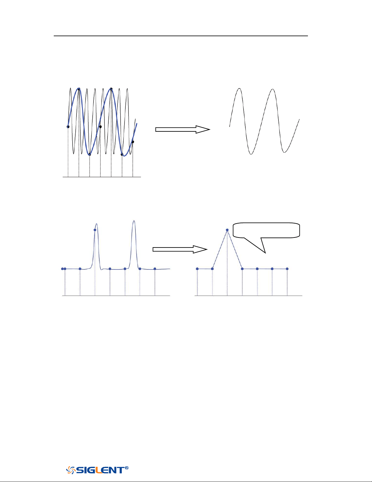
SDS1000X-E&SDS1000X-U User Manual
44
WWW.SIGLENT.COM
2. Waveform Confusion: when the sample rate is lower than twice the actual
signal frequency (Nyquist Frequency), the frequency of the waveform rebuilt
from the sample data is lower than the actual signal frequency. The most
common aliasing is the jitter on fast edge.
3.
Waveform Leakage: when the sample rate is too low, the waveform rebuilt
from the sample data does not reflect all the actual signal information.
Bandwidth and Sample Rate
An oscilloscope's bandwidth is typically described as the lowest frequency at which
input signal sine waves are attenuated by 3 dB (- 30% amplitude error).
At the oscilloscope bandwidth, sampling theory says the required sample rate is f
S
= 2f
BW
. However, the theory assumes there are no frequency components above f
MAX
(f
BW
in this case) and it requires a system with an ideal brick- wall frequency
response.
Pulse disappeared
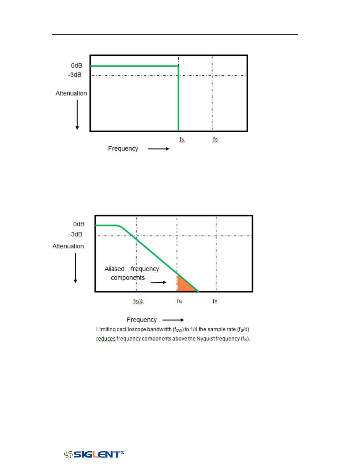
SDS1000X-E&SDS1000X-U User Manual
45
WWW.SIGLENT.COM
However, digital signals have frequency components above the fundamental
frequency (square waves are made up of sine waves at the fundamental frequency
and an infinite number of odd harmonics), and typically, for 500 MHz bandwidths
and below, oscilloscopes have a Gaussian frequency response.
So, in practice, an oscilloscope's sample rate should be four or more times its
bandwidth: f
S
= 4fBW. This way, there is less aliasing, and aliased frequency
components have a greater amount of attenuation.
SDS1000X-E&SDS1000X-U User Manual
46
WWW.SIGLENT.COM
Memory Depth
Memory depth refers to the number of waveform points that the oscilloscope can
store in a single trigger sample and it reflects the storage ability of the sample
memory.
Press the Acquire button on the front panel; press the Mem Depth softkey and then
turn the Universal Knob to select the desired value and push down the knob to
confirm. Press the Mem Depth softkey continually can also select the desired value.
The actual memory depth is displayed in the information area at the upper- right
corner of the screen. Since the oscilloscope of SDS1000X-E has two acquisition
memories, when only one channel is on, the maximal memory depth is up to 14
Mpts. SDS1000X-U only has one acquisition memory, when only one channel is on,
the maximal memory depth is up to 14 Mpts.
The maximum storage depth in single channel mode is twice that in dual channel
mode, as shown in the following table:
SDS1000X-E
SDS1000X-U
Single
Channel Mode
Dual Channel
Mode
Single
Channel Mode
Dual Channel
Mode
Three or Four
Channel Mode
14k
7k
14k
7k
3.5k
140k
70k
140k
70k
35k
1.4M
700k
1.4M
700k
350k
14M
7M
14M
7M
3.5M
The relation of memory depth, sample rate and waveform length fulfills the
equation below:
Memory depth = sample rate (Sa/s) × waveform length (s/div × div)
Sampling Mode
The oscilloscope only supports real-time sample. In this mode, the oscilloscope
samples and displays waveform within a trigger event. The maximum real-time
sample rate is 1GSa/s.
Press the
RUN/STOP button to stop the sample, the oscilloscope will hold the last
display. At this point, you can still use the vertical control and horizontal control to

SDS1000X-E&SDS1000X-U User Manual
47
WWW.SIGLENT.COM
pan and zoom the waveform.
Interpolation Method
Under real-time sampling, the oscilloscope acquires the discrete sample values of
the waveform being displayed. In general, a waveform of dots display type is very
difficult to observe. In order to increase the visibility of the signal, the digital
oscilloscope usually uses the interpolation method to display a waveform.
Interpolation method is a processing method to “connect all the sampling
points”, and using some points to calculate the whole appearance of the
waveform. For real-time sampling interpolation method is used, even if the
oscilloscope in a single captures only a small number of sampling points. The
oscilloscope can use interpolation method for filling out the gaps between points,
to reconstruct an accurate waveform.
Press the
Acquire button on the front panel to enter the ACQUIRE Function menu;
then press the Interpolation softkey to select Sinx/x or X.
X: In the adjacent sample points are directly connected on a straight line. This
method is only confined to rebuild on the edge of signals, such as square
wave.
Sinx/x: Connecting the sampling points with curves has stronger versatility.
Sinx interpolation method uses mathematical processing to calculation results
in the actual sample interval. This method bending signal waveform, and
make it produce more realistic regular shape than pure square wave and pulse.
When the sampling rate is 3 to 5 times the bandwidth of the system.
Recommended Sinx/s interpolation method.
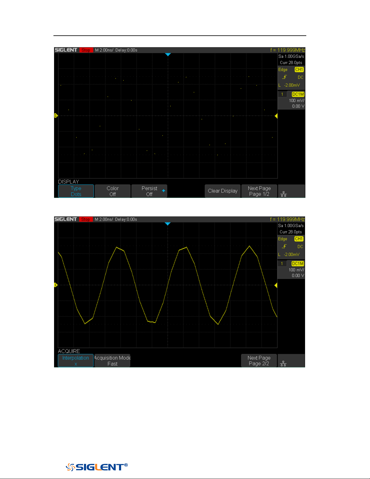
SDS1000X-E&SDS1000X-U User Manual
48
WWW.SIGLENT.COM
Figure 19 Display Type Set to Dots
Figure 20 x
Interpolation
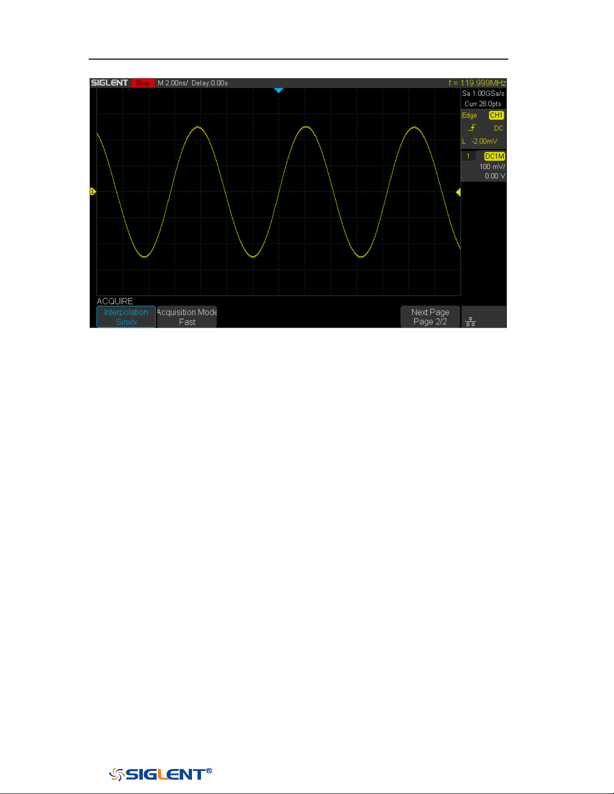
SDS1000X-E&SDS1000X-U User Manual
49
WWW.SIGLENT.COM
Figure 21 Sinx/x
Interpolation
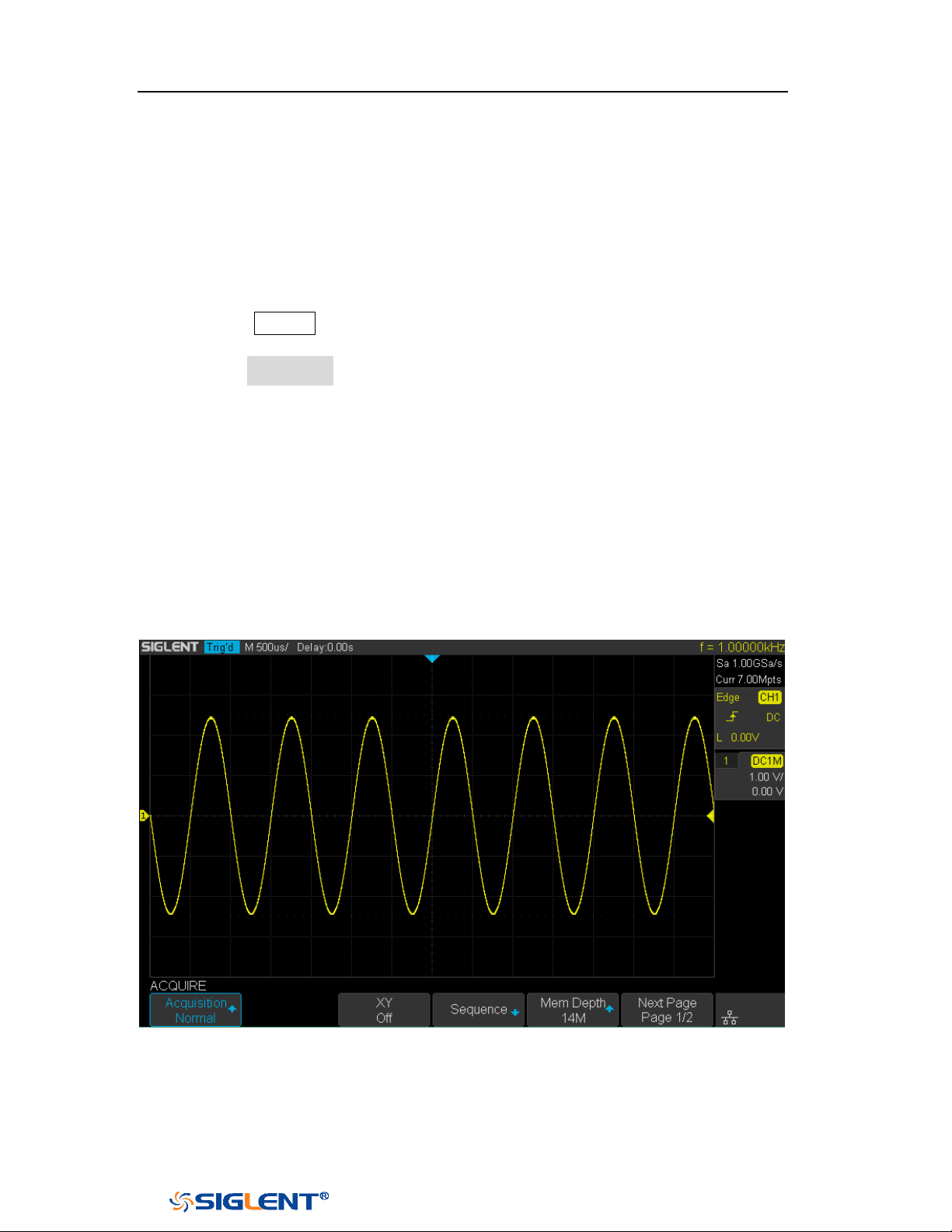
SDS1000X-E&SDS1000X-U User Manual
50
WWW.SIGLENT.COM
Acquisition Mode
The acquisition mode is used to control how to generate waveform points from
sample points. The oscilloscope provides the following acquisition mode: Normal,
Peak Detect, Average and Eres.
1. Press the
Acquire button on the front panel to enter the ACQUIRE function
menu;
2. Press the Acquisition softkey; then turn the Universal Knob to select the desired
acquisition mode and push down the knob to confirm. The default setup is
Normal.
Normal
In this mode, the oscilloscope samples the signal at equal time interval to rebuild
the waveform. For most of the waveforms, the best display effect can be obtained
using this mode. It is the default acquisition mode.
Figure 22 Acquisition System
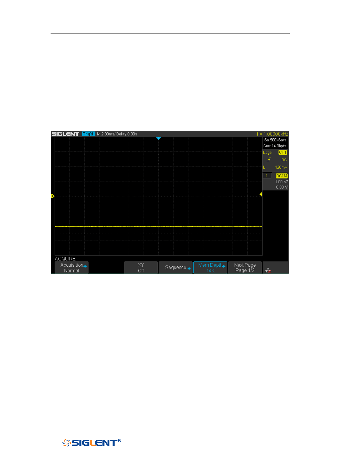
SDS1000X-E&SDS1000X-U User Manual
51
WWW.SIGLENT.COM
Peak Detect
In this mode, the oscilloscope acquires the maximum and minimum values of the
signal within the sample interval to get the envelope of the signal or the narrow
pulse of the signal that might be lost. In this mode, signal confusion can be
prevented but the noise displayed would be larger.
In this mode, the oscilloscope can display all the pulses with pulse widths at least
as wide as the sample period.
Figure 23 Pulse With 0.1% Duty, Normal Mode
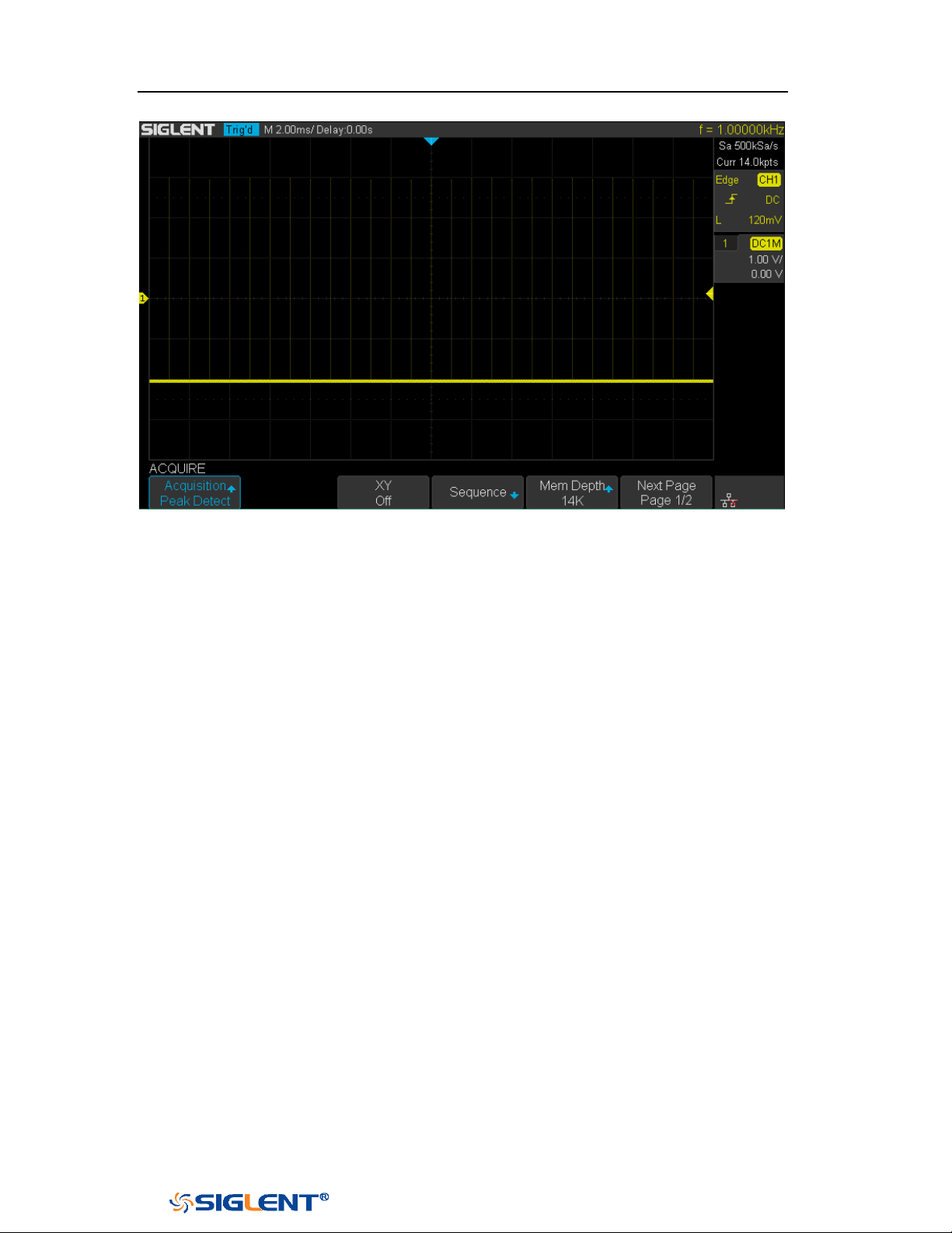
SDS1000X-E&SDS1000X-U User Manual
52
WWW.SIGLENT.COM
Figure 24 Pulse With 0.1% Duty, Peak Detect Mode
Average
In this mode, the oscilloscope averages the waveforms from multiple samples to
reduce the random noise of the input signal and improve the vertical resolution.
The greater the number of averages is, the lower the noise will be and the higher
the vertical resolution will be but the slower the response of the displayed
waveform to the waveform changes will be.
The available range of averages is from 4 to 1024 and the default is 16. When
Average mode is selected, press
Averages and turn the Universal knob or press the
softkey continually to set the desired average time.
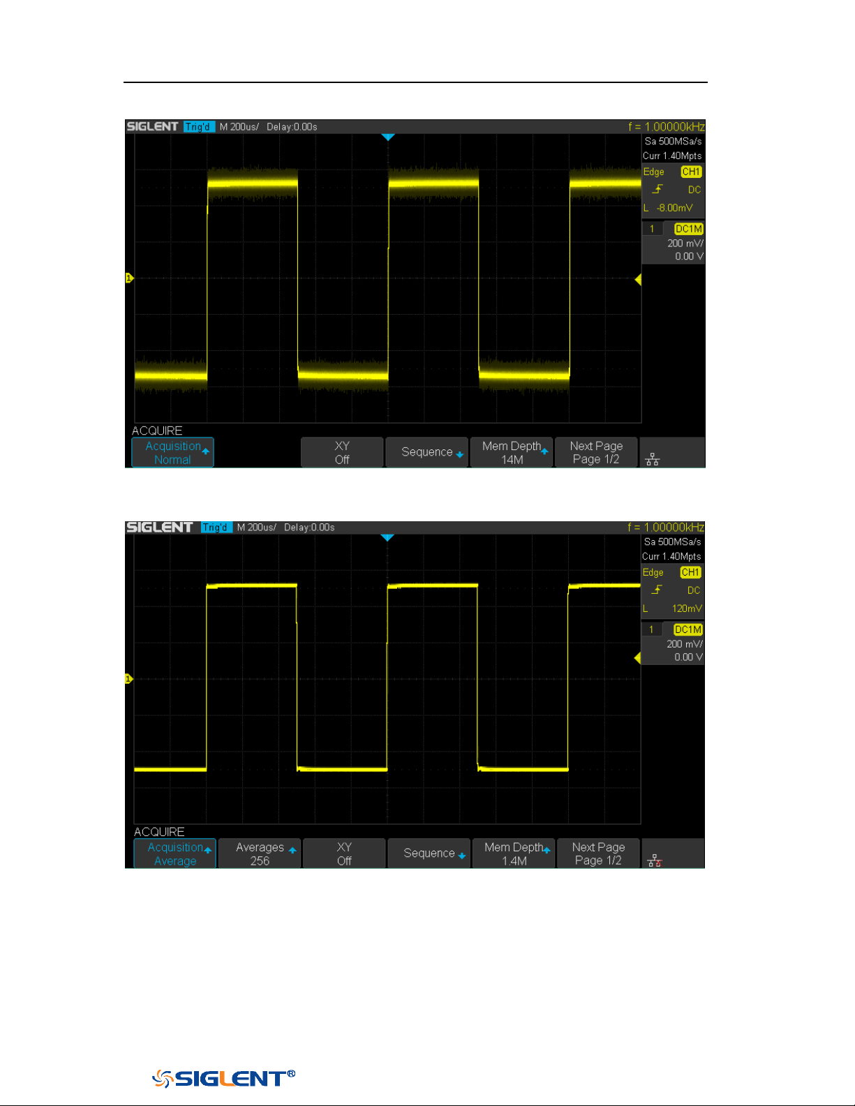
SDS1000X-E&SDS1000X-U User Manual
53
WWW.SIGLENT.COM
Figure 25 with Random Noise, Normal Mode
Figure 26 with Random Noise, Average Mode
Eres
This mode uses a kind of ultra-sample technique to average the neighboring points

SDS1000X-E&SDS1000X-U User Manual
54
WWW.SIGLENT.COM
Note: “Average” and “Eres” modes use different averaging methods. The
former uses “Waveform Average” and the latter uses “Dot Average”.
of the sample waveform to reduce the random noise on the input signal and
generate much smoother waveforms on the screen. This is generally used when the
sample rate of the digital converter is higher than the storage rate of the
acquisition memory.
Eres mode can be used on both single- shot and repetitive signals and it does not
slow waveform update. This mode limits the oscilloscope's real- time bandwidth
because it effectively acts like a low- pass filter.

SDS1000X-E&SDS1000X-U User Manual
55
WWW.SIGLENT.COM
Horizontal Format
Press the Acquire button on the front panel; then press the XY soft key to set the
XY(On) or YT(Off) mode. The default setup is YT.
YT
It is the normal viewing mode for the oscilloscope. In the Normal time mode, signal
events occurring before the trigger are plotted to the left of the trigger point and
signal events after the trigger plotted to the right of the trigger point.
XY
XY mode changes the display from a volt- versus- time display to a volt- versus-
volt display. Channel 1 amplitude is plotted on the X- axis and Channel 2 amplitude
is plotted on the Y- axis, the two channels will be turned on or off together.
You can use XY mode to compare frequency and phase relationships between two
signals. XY mode can also be used with transducers to display strain versus
displacement, flow versus pressure, volts versus current, or voltage versus
frequency.
The phase deviation between two signals with the same frequency can be easily
measured via Lissajous method. The figure below shows the measurement
schematic diagram of the phase deviation
According to
sinθ=A/B or C/D (wherein, θ is the phase deviation angle between the
two channels and the definitions of A, B, C and D are as shown in the figure above),
the phase deviation angle is obtained, that is: θ=±arcsin (A/B) or ±arcsin (C/D)

SDS1000X-E&SDS1000X-U User Manual
56
WWW.SIGLENT.COM
If the principal axis of the ellipse is within quadrant I and III, the phase deviation
angle obtained should be within quadrant I and IV, namely within (0 to π/2) or
(3π/2 to 2π). If the principal axis of the ellipse is within quadrant II and IV, the
phase deviation angle obtained should be within quadrant II and III, namely within
(π/2 to π) or (π to 3π/2).
X-Y function can be used to measure the phase deviation occurred when the signal
under test passes through a circuit network. Connect the oscilloscope to the circuit
to monitor the input and output signals of the circuit.
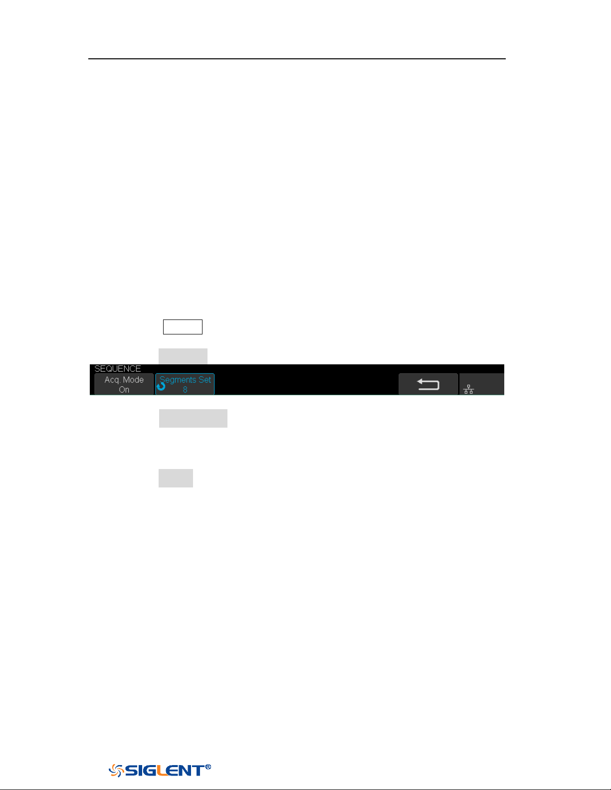
SDS1000X-E&SDS1000X-U User Manual
57
WWW.SIGLENT.COM
Sequence Mode
Sequence is also a kind of acquisition mode, which does not display waveform
during sampling process. It improves the waveform capture rate, and the maximal
capture rate is 400,000 wfs/s. So it can capture the small probability event
effectively.
The oscilloscope runs and fills a memory segment for each trigger event. The
oscilloscope is busy acquiring multiple segments. The oscilloscope continues to
trigger until memory is filled, and then display the waveforms on the screen.
To use the sequence mode, the HORIZONTAL Format must be set to
YT.
Do the following steps to use the sequence mode.
1. Press the Acquire button on the front panel to enter the ACQUIRE function
menu;
2. Press the Sequence softkey to enter the SEQUENCE function menu.
Figure 27 SEQUENCE Function Menu
3. Press the Segments Set softkey; and then turn the Universal Knob to select the
desired value.
Do the following steps to replay the sequence waveform under history mode:
1. Press the History softkey to enable HISTORY function.
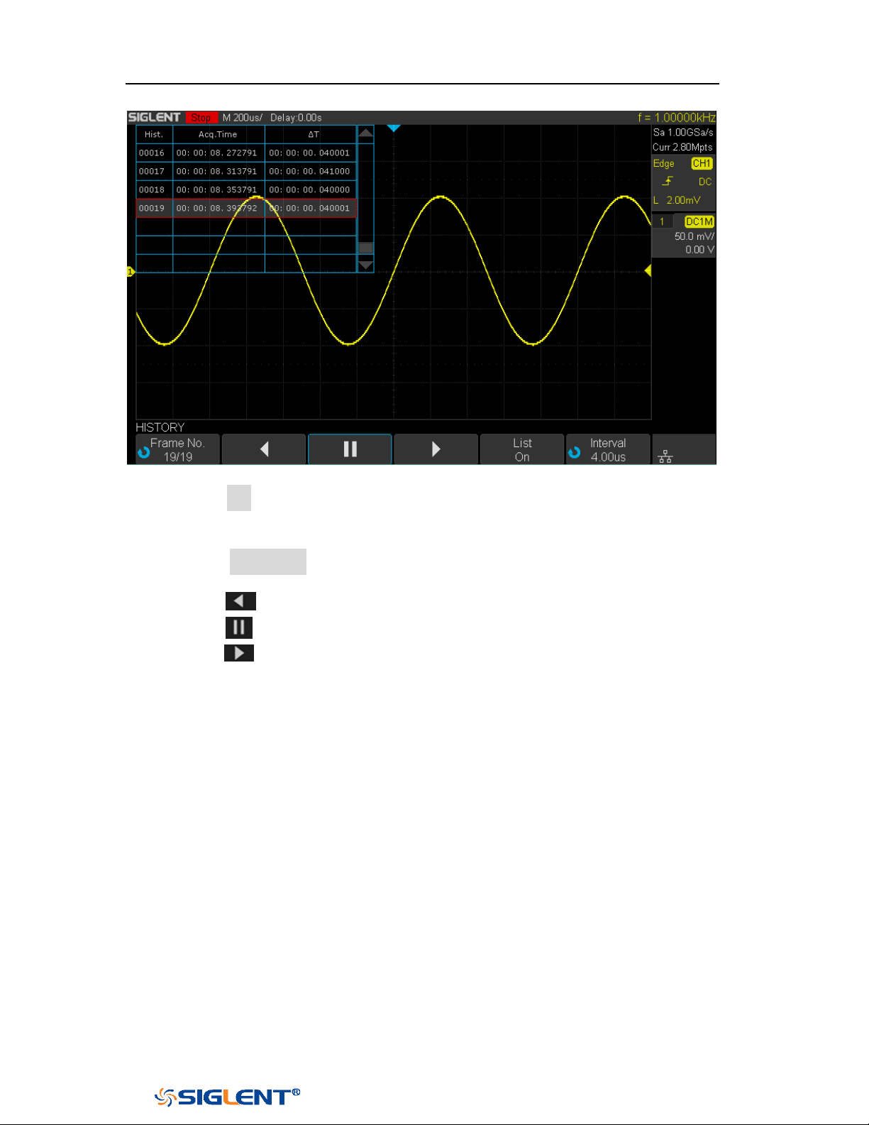
SDS1000X-E&SDS1000X-U User Manual
58
WWW.SIGLENT.COM
Figure 28 HISTORY Function Menu
2. Press the List softkey to turn on the list display. The list records the acquisition
time of every frame and shows the frame number that displaying on the
screen.
3. Press the Frame No. softkey; and then turn the Universal Knob to select the
frame to display.
4. Press the softkey to replay the waveform from the current frame to 1.
5. Press the softkey to stop replay.
6. Press the softkey to replay the waveform from the current frame to the
last frame.
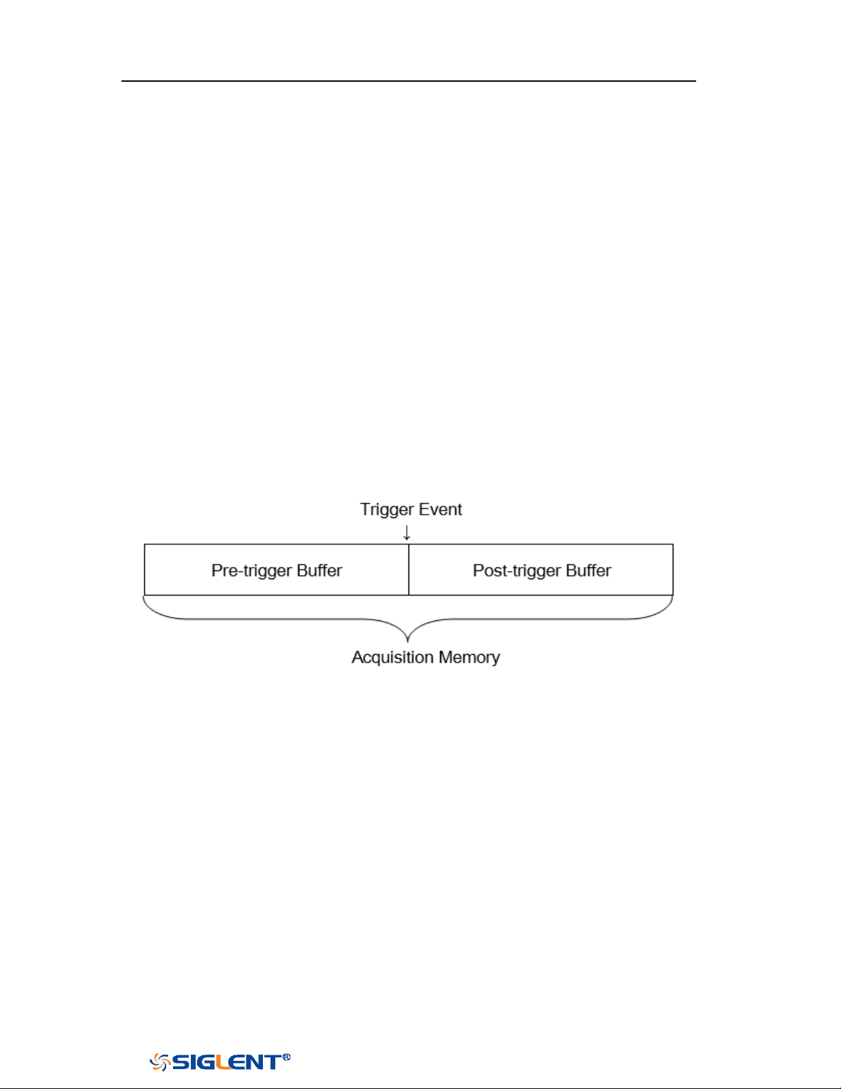
SDS1000X-E&SDS1000X-U User Manual
59
WWW.SIGLENT.COM
Trigger
For trigger, you set certain trigger condition according to the requirement and
when a waveform in the waveform stream meets this condition, the oscilloscope
captures this waveform as well as the neighboring part and displays them on the
screen. For digital oscilloscope, it displays waveform continuously no matter
whether it is stably triggered, but only stable trigger can ensures stable display.
The trigger circuit ensures that every time base sweep or acquisition starts from the
input signal and the user-defined trigger condition, namely every sweep is
synchronous to the acquisition and the waveforms acquired overlap to display
stable waveform.
The following is the schematic diagram of the acquisition memory. As shown in the
figure below, the position of the trigger event is determined by the reference time
point and the delay setting.
Trigger setting should be based on the features of the input signal, thus you need
to have some knowledge of the signal under test to quickly capture the desired
waveform.
The oscilloscope provides abundant advanced trigger functions which can help
you to focus on the desired waveform details. These trigger types are edge, slope,
pulse, video, window, interval, dropout, runt, pattern and serial trigger. This
chapter will mainly introduce all these trigger functions which mentioned above in
details and tell you how to set the trigger conditions to capture desired waveform.
The contents of this chapter:

SDS1000X-E&SDS1000X-U User Manual
60
WWW.SIGLENT.COM
Trigger Source
Trigger Mode
Trigger Level
Trigger Coupling
Trigger Holdoff
Noise Rejection
Trigger Type
SDS1000X-E&SDS1000X-U User Manual
61
WWW.SIGLENT.COM
Note: to select stable channel waveform as the trigger source to stabilize the
display.
Trigger Source
The 2-channel oscilloscope’s trigger source includes analog channels,
EXT, EXT/5
and AC Line. The 4-channel oscilloscope’s trigger source includes analog channels
and AC Line.
Press the Setup button on the front panel to enter the TRIGGER function menu;
press the Source softkey and then turn the Universal Knob to select the desired
trigger source.
The current trigger source is displayed at the upper right corner of the screen.
Select channel with signal input as trigger source to obtain stable trigger.
Analog channel input:
Signals input from analog channels can all be used as the trigger source.
External trigger input:
External trigger source can be used to connect external trigger signal to the EXT
TRIG channel when all of the four channels are sampling data. The trigger signal
(such as external clock and signal of the circuit to be tested) will be connected to
EXT and EXT/5 trigger source via the [EXT TRIG] connector. EXT/5 trigger source
attenuates the signal by a factor of 5. It extends the trigger level. You can set the
trigger condition within the range of trigger level (-8 div to +8 div).
AC line:
The trigger signal is obtained from the AC power input of the oscilloscope. This kind
of signals can be used to display the relationship between signal (such as
illuminating device) and power (power supply device). For example, it is mainly
used in related measurement of the power industry to stably trigger the waveform
output from the transformer of a transformer substation.

SDS1000X-E&SDS1000X-U User Manual
62
WWW.SIGLENT.COM
Trigger Mode
The oscilloscope’s trigger mode includes auto, normal and single. Trigger mode
affects the way in which the oscilloscope searches for the trigger
After the oscilloscope starts running, the oscilloscope operates by first filling the
pre-trigger buffer. It starts searching for a trigger after the pre-trigger buffer is
filled and continues to flow data through this buffer while it searches for the trigger.
While searching for the trigger, the oscilloscope overflows the pre-trigger buffer
and the first data put into the buffer is first pushed out (First Input First Out, FIFO).
When a trigger is found, the pre- trigger buffer contains the events that occurred
just before the trigger. Then, the oscilloscope fills the post- trigger buffer and
displays the acquisition memory.
Press the
Auto, Normal and the Single buttons on the front panel to select the
desired trigger mode, and the corresponding status light will be lighted.
In the Auto trigger mode (the default setting), if the specified trigger conditions
are not found, triggers are forced and acquisitions are made so hat signal
activity is displayed on the oscilloscope.
The Auto trigger mode is appropriate when:
Checking DC signals or signals with unknown levels or activity.
When trigger conditions occur often enough that forced triggers are
unnecessary.
In the
Normal trigger mode, triggers and acquisitions only occur when the
specified trigger conditions are found. Otherwise, the oscilloscope holds the
original waveform and waits for the next trigger.
The Normal trigger mode is appropriate when:
You only want to acquire specific events specified by the trigger settings.
Triggering on an infrequent signal from a serial bus (for example, I2C, SPI,
CAN, LIN, etc.) or another signal that arrives in bursts. The Normal trigger
mode lets you stabilize the display by preventing the oscilloscope from
auto- triggering.
In the
Single trigger mode, the oscilloscope waits for a trigger and displays the
waveform when the trigger condition is met and then stops.
The Single trigger mode is appropriate when:

SDS1000X-E&SDS1000X-U User Manual
63
WWW.SIGLENT.COM
Note: You can force the oscilloscope to trigger by pressing the Single button
twice. The trigger status in the upper left corner of the screen will be displayed
as "FStop".
To capture single event or a periodic signal.
To capture burst or other unusual signals.

SDS1000X-E&SDS1000X-U User Manual
64
WWW.SIGLENT.COM
Trigger Level
Trigger level and slope define the trigger point,
You can adjust the trigger level for a selected analog channel by turning the
Trigger Level Knob.
You can push the Trigger Level Knob to set the level to the waveform's 50% value
immediately. If AC coupling is used, pushing the Trigger Level knob sets the trigger
level to about 0 V.
The position of the trigger level for the analog channel is indicated by the trigger
level icon (if the analog channel is on) at the left side of the display. The value of
the analog channel trigger level is displayed in the upper- right corner of the
display.

SDS1000X-E&SDS1000X-U User Manual
65
WWW.SIGLENT.COM
Note: trigger coupling has nothing to do with the channel coupling.
Trigger Coupling
Press the Setup button on the front panel to enter the TRIGGER function menu, and
then press the Coupling softkey and turn the Universal Knob or press the Coupling
softkey continually to select the desired coupling mode.
The oscilloscope provides 4 kinds of trigger coupling modes:
DC: allow DC and AC components into the trigger path.
AC: block all the DC components and attenuate signals lower than 8 Hz. Use AC
coupling to get a stable edge trigger when your waveform has a large DC
offset.
LF Reject: block the DC components and reject the low frequency components
lower than 2 MHz. Low frequency reject removes any unwanted low frequency
components from a trigger waveform, such as power line frequencies, etc. that
can interfere with proper triggering. Use LF Reject coupling to get a stable
edge trigger when your waveform has low frequency noise.
HF Reject: reject the high frequency components higher 1.2 MHz)
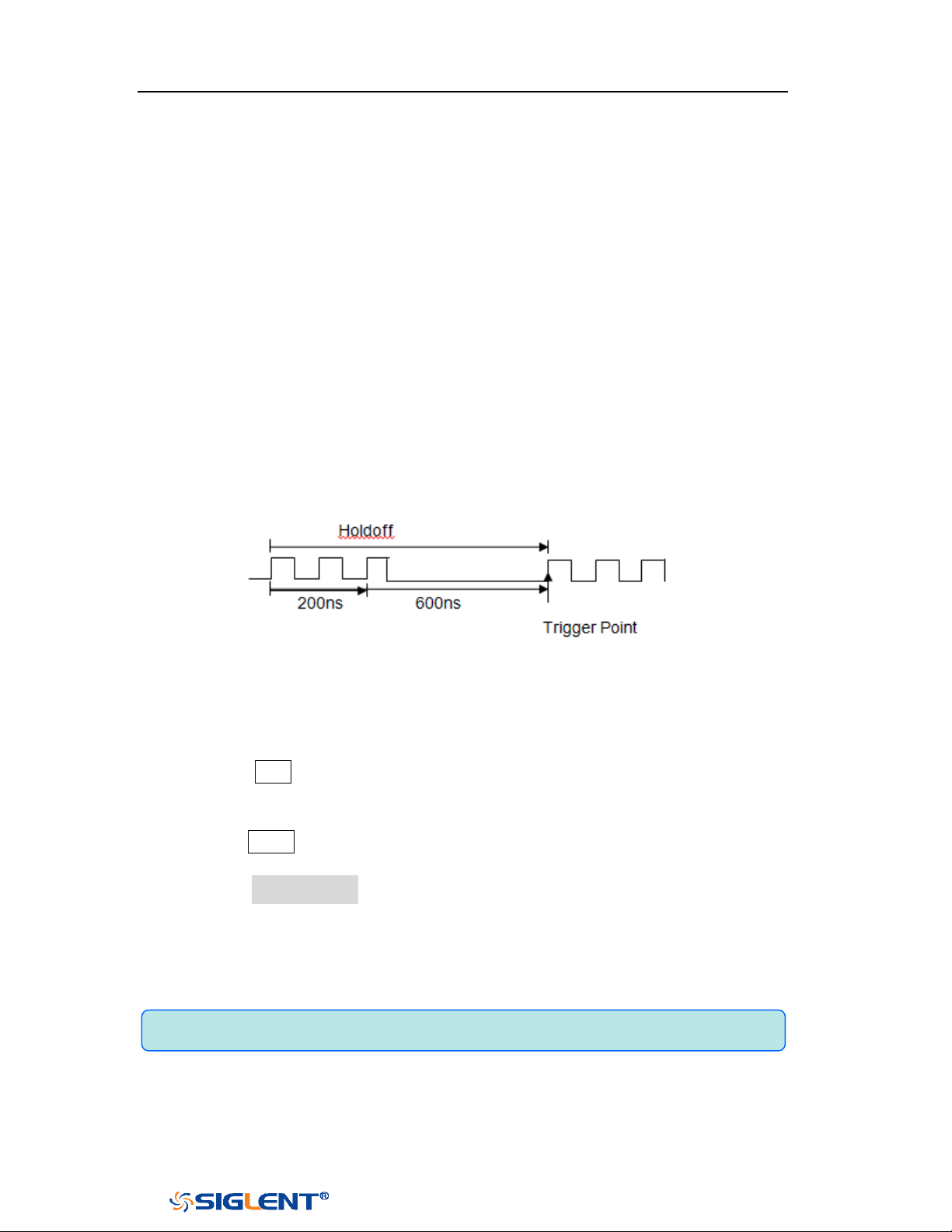
SDS1000X-E&SDS1000X-U User Manual
66
WWW.SIGLENT.COM
Note: adjust the time scale and horizontal position will not affect the holdoff
time.
Trigger Holdoff
Trigger holdoff can be used to stably trigger the complex waveforms (such as pulse
series). Holdoff time is the amount of time that the oscilloscope waits before
re-arming the trigger circuitry. The oscilloscope will not trigger until the holdoff
time expires.
Use the holdoff to trigger on repetitive waveforms that have multiple edges (or
other events) between waveform repetitions. You can also use holdoff to trigger on
the first edge of a burst when you know the minimum time between bursts.
For example, to get a stable trigger on the repetitive pulse burst shown below, set
the holdoff time to be >200 ns but <600 ns.
The correct holdoff setting is typically slightly less than one repetition of the
waveform. Set the holdoff to this time to generate a unique trigger point for a
repetitive waveform. Only edge trigger and serial trigger have holdoff option. The
holdoff time of the oscilloscope is adjustable from 80ns to 1.5s.
1. Press the
Stop button, and then use the Horizontal Position Knob and the
Horizontal Scale Knob to find where the waveform repeats. Measure this time
using cursors; then, set the holdoff.
2. Press the Setup button on the front panel to enter the TRIGGER function menu.
The default trigger type is edge.
3. Press the Holdoff Close softkey; and then turn the Universal Knob to set the
desired holdoff time.
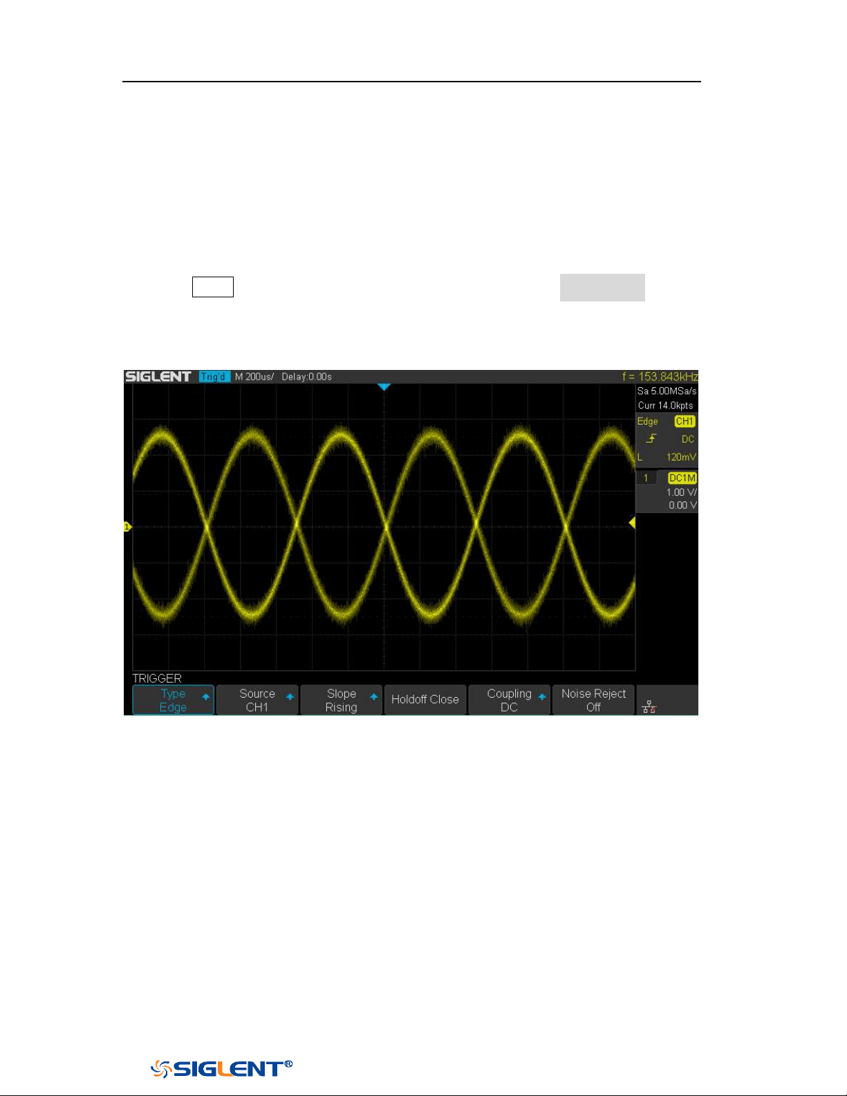
SDS1000X-E&SDS1000X-U User Manual
67
WWW.SIGLENT.COM
Noise Rejection
Noise Reject adds additional hysteresis to the trigger circuitry. By increasing the
trigger hysteresis band, you reduce the possibility of triggering on noise. However,
this also decreases the trigger sensitivity so that a slightly larger signal is required
to trigger the oscilloscope.
Press the Setup button on the front panel, and then press the Noise Reject softkey
continually to set the option to On or Off to turn on or off the noise rejection
function.
Figure 29 Turn off the Noise Reject
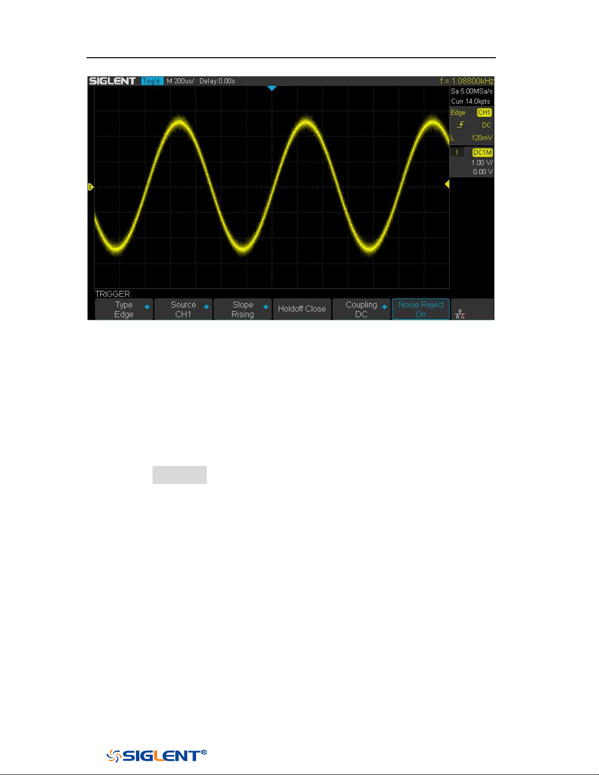
SDS1000X-E&SDS1000X-U User Manual
68
WWW.SIGLENT.COM
Figure 30 Turn on the Noise Reject
If the signal you are probing is noisy, you can set up the oscilloscope to reduce the
noise in the trigger path and on the displayed waveform. First, stabilize the
displayed waveform by removing the noise from the trigger path. Second, reduce
the noise on the displayed waveform.
1. Connect a signal to the oscilloscope and obtain a stable display.
2. Remove the noise from the trigger path by setting trigger coupling to
LF Reject,
HF Reject or turning on Noise Reject.
3. Set the Acquisition option to Average to reduce noise on the displayed
waveform.

SDS1000X-E&SDS1000X-U User Manual
69
WWW.SIGLENT.COM
Trigger Type
The oscilloscope provides abundant advanced trigger functions, including various
serial bus triggers.
Edge trigger
Slope trigger
Pulse trigger
Video trigger
Window trigger
Interval trigger
Dropout trigger
Runt trigger
Pattern trigger
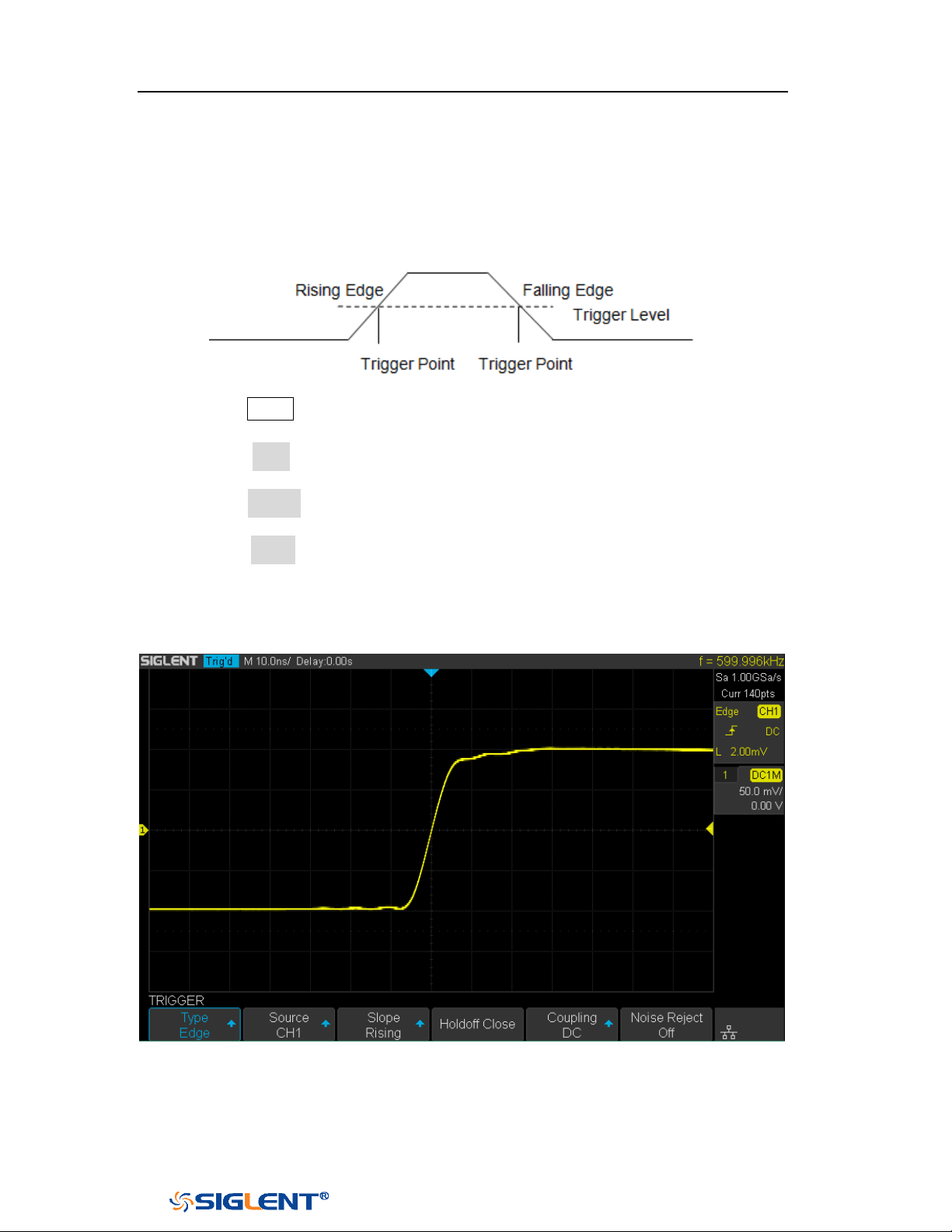
SDS1000X-E&SDS1000X-U User Manual
70
WWW.SIGLENT.COM
Edge Trigger
Edge trigger distinguishes the trigger points by seeking the specified edge (rising,
falling, alternating) and trigger level.
1. Press the
Setup button on the front panel to enter the TRIGGER system function
menu.
2. Press the Type softkey; turn the Universal Knob to set select Edge and then
push the knob to confirm.
3. Press the Source softkey; turn the Universal Knob to select the deserted trigger
source.
4. Press the Slope softkey; turn the Universal Knob to select the desired trigger
edge (rising, falling or alternating), and then press down the knob to confirm.
The current trigger slope is displayed at the upper right corner of the screen.
5. Turn the Trigger Level Knob to adjust the trigger level to obtain stable trigger.
Figure 31 Edge Trigger
Holdoff, coupling and noise reject can be set in edge trigger, see the sections
"Trigger Holdoff", "Trigger Coupling" and "Noise Rejection" for details.

SDS1000X-E&SDS1000X-U User Manual
71
WWW.SIGLENT.COM
Note: Press the Auto Setup button will set the trigger type to Edge and slope to
rising.
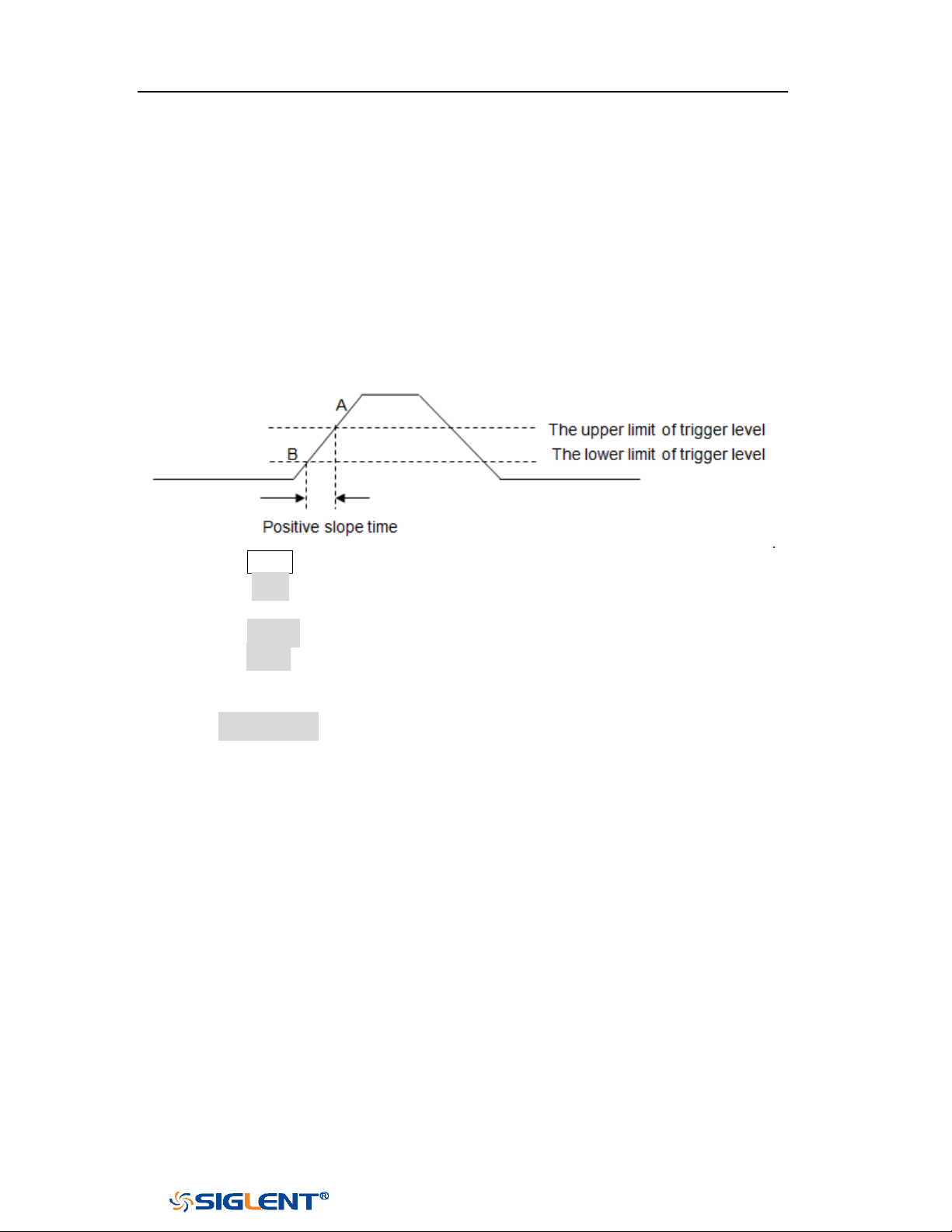
SDS1000X-E&SDS1000X-U User Manual
72
WWW.SIGLENT.COM
Slope Trigger
The slope trigger looks for a rising or falling transition from one level to another
level in greater than or less than a certain amount of time.
In the oscilloscope, positive slope time is defined as the time difference between
the two crossing points of trigger level line A and B with the positive edge as shown
in the figure below.
1. Press the
Setup button on the front panel to enter the TRIGGER function menu.
2. Press the Type softkey; turn the Universal Knob to set select Slope and then
push the knob to confirm.
3. Press the Source softkey; turn the Universal Knob to select the trigger source.
4. Press the Slope softkey; turn the Universal Knob to set select the desired trigger
edge (rising or falling), and then push down the knob to confirm. The current
trigger slope is displayed at the upper right corner of the screen.
5. Press Lower Upper softkey to select the Lower or Upper trigger level; then turn
the Trigger Level Knob to adjust the position. The trigger level values are
displayed at the upper right corner of the screen.
The lower trigger level cannot be upper than the upper trigger level. In the
trigger state message box, L1 means the upper trigger lever while L2 means
the lower trigger level.
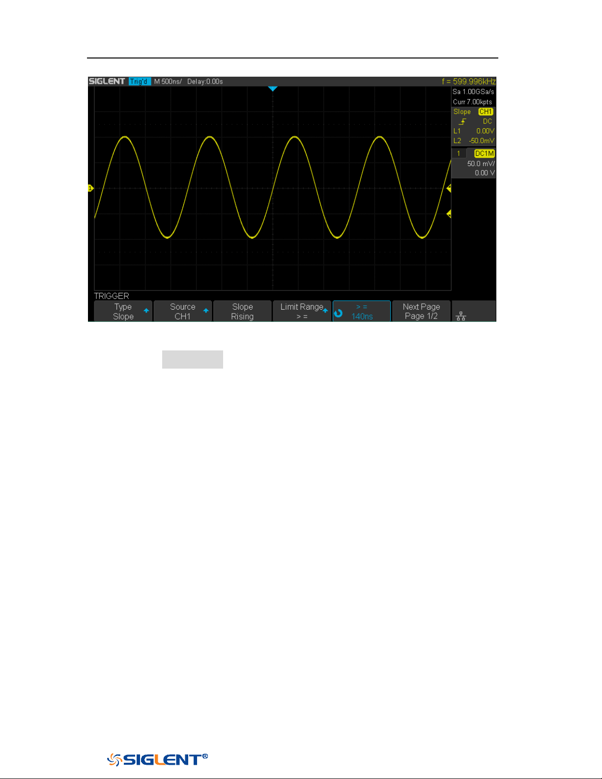
SDS1000X-E&SDS1000X-U User Manual
73
WWW.SIGLENT.COM
Figure 32 Slope Trigger
6. Press the Limit Range softkey; then turn the Universal Knob to select the
desired slope condition, and push down the knob to confirm.
<= (less than a time value): trigger when the positive or negative slope
time of the input signal is lower than the specified time value.
>= (greater than a time value): trigger when the positive or negative slope
time of the input signal is greater than the specified time value.
[--,--] (within a range of time value):trigger when the positive or negative
slope time of the input signal is greater than the specified lower limit of
time and lower than the specified upper limit of time value.
--][-- (outside a range of time value): trigger when the positive or negative
slope time of the input signal is greater than the specified upper limit of
time and lower than the specified lower limit of time value.
Coupling and noise reject can be set in slope trigger, see the sections "Trigger
Coupling" and "Noise Rejection" for details.
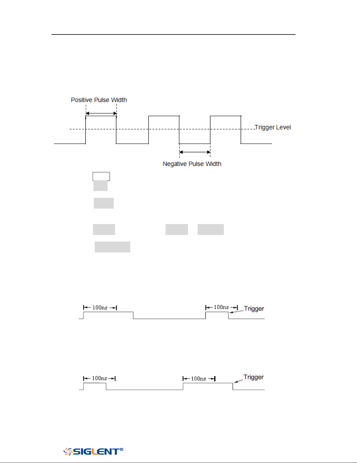
SDS1000X-E&SDS1000X-U User Manual
74
WWW.SIGLENT.COM
Pulse Trigger
Trigger on the positive or negative pulse with a specified width.
1. Press the Setup button on the front panel to enter the TRIGGER function menu.
2. Press the Type softkey; turn the Universal Knob to select Pulse and then push
the knob to confirm.
3. Press the Source softkey; turn the Universal Knob to select CH1 or CH2 as the
trigger source.
4. Turn the Trigger Level Knob to adjust the trigger level to the desired place.
5. Press the Polarity softkey to select Positive or Negative pulse that to trigger on.
The current trigger polarity is displayed at the upper right corner of the screen.
6. Press the Limit Range softkey; turn the Universal Knob to select the desired
condition.
<= (less than a time value): trigger when the positive or negative pulse
time of the input signal is lower than the specified time value.
For example, for a positive pulse, if you set t (pulse real width) ≤ 100ns,
the waveform will trigger.
>= (greater than a time value): trigger when the positive or negative pulse
time of the input signal is greater than the specified time value.
For example, for a positive pulse, if you set t (pulse real width) ≥ 100ns,
the waveform will trigger.
[--,--] (within a range of time value):trigger when the positive or negative
pulse time of the input signal is greater than the specified lower limit of
time and lower than the specified upper limit of time value.
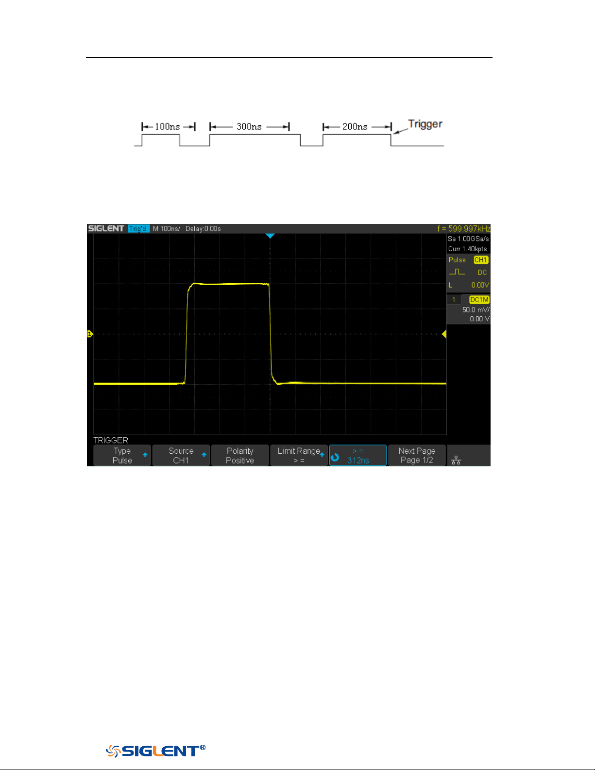
SDS1000X-E&SDS1000X-U User Manual
75
WWW.SIGLENT.COM
For example, for a positive pulse, if you set t (pulse real width) ≥100ns and
t ≤ 300ns, the waveform will trigger.
--][-- (outside a range of time value): trigger when the positive or negative
pulse time of the input signal is greater than the specified upper limit of
time and lower than the specified lower limit of time value.
Figure 33 Pulse Trigger
Coupling and noise reject can be set in pulse trigger, see the sections "Trigger
Coupling" and "Noise Rejection" for details.
SDS1000X-E&SDS1000X-U User Manual
76
WWW.SIGLENT.COM
Video Trigger
Video triggering can be used to capture the complicated waveforms of most
standard analog video signals. The trigger circuitry detects the vertical and
horizontal interval of the waveform and produces triggers based on the video
trigger settings you have selected.
The oscilloscope supports standard video signal field or line of NTSC (National
Television Standards Committee), PAL (Phase Alternating Line) HDTV (High
Definition Television) and custom video signal trigger.
1. Press the
Setup button on the front panel to enter the TRIGGER function menu.
2. Press the Type softkey; then turn the Universal Knob to select Video and push
down the knob to confirm.
3. Press the Source softkey; turn the Universal Knob to select CH1 or CH2 as the
trigger source. Turn the Trigger Level Knob does not change the trigger level
because the trigger level is automatically set to the sync pulse.
4. Press the Standard softkey to select the desired video standard. The
oscilloscope supports the following video standards.
Standard
Type
Sync Pulse
NTSC
Interlaced
BI-level
PAL
Interlaced
BI-level
HDTV 720P/50
Progressive
Tri-level
HDTV 720P/60
Progressive
Tri-level
HDTV 1080P/50
Progressive
Tri-level
HDTV 1080P/60
Progressive
Tri-level
HDTV 1080i/50
Progressive
Tri-level
HDTV 1080i/50
Progressive
Tri-level
Custom
The table below shows the parameters of the Custom video trigger.
Frame Rate
25Hz, 30Hz, 50Hz, 60Hz
Of Lines
300~2000
Of Fields
1, 2, 3, 4
Interlace
1:1, 2:1, 4:1, 8:1
Trigger Position
Line
Field
(line value)/1
1
(line value)/2
2
(line value)/3
3
(line value)/4
4
(line value)/5
5
(line value)/6
6
SDS1000X-E&SDS1000X-U User Manual
77
WWW.SIGLENT.COM
(line value)/7
7
(line value)/8
8
The table below takes Of Lines as 800 as an example to explain the relation
between Of Lines, Of Fields, Interlace, Trigger Line and Trigger Field.
Of Lines
Of Fields
Interlace
Trigger Line
Trigger Field
800
1
1:1
800
1
800
1,2,4 or 8
2:1
400
1, 1~2, 1~4, 1~8
800
1,2,4 or 8
4:1
200
1, 1~2, 1~4, 1~8
800
1,2,4 or 8
8:1
100
1, 1~2, 1~4, 1~8
5. Press the Sync softkey to select Any or Select trigger mode.
Any: trigger on any of the horizontal sync pulses
Select: trigger on the appointed line and field you have set. Press the Line
or Field softkey; then turn the Universal Knob to set the value.
The following table lists the line numbers per field for each video standard.
Standard
Field 1
Field 2
NTSC
1 to 262
1 to 263
PAL
1 to 312
1 to 313
HDTV 720P/50, HDTV 720P/60
1 to 750
HDTV 1080P/50, HDTV 1080P/60
1 to 1125
HDTV 1080iP/50, HDTV 1080i/60
1 to 562
1 to 563
The following are exercises to familiarize you with video triggering.
To trigger on a specific line of video
To use Custom video trigger
To Trigger on a Specific Line of Video
Video triggering requires greater than 1/2 division of sync amplitude with any
analog channel as the trigger source.
The example below set to trigger on field 2, line 124 using the NTSC video standard.
1. Press the Setup button on the front panel to enter the TRIGGER system function
menu.
2. Press the Type softkey; then use the Universal Knob to select Video and push
down the knob to confirm.
3. Press the Source softkey; turn the Universal Knob to select CH1 as the trigger
source, and press the knob to confirm.
4. Press the Standard softkey; turn the Universal Knob to select NTSC, and press
the knob to confirm.
5. Press the Sync softkey and set the option to Select; press the Line softkey and
then turn the universal to select 022 and push the knob to confirm; press the
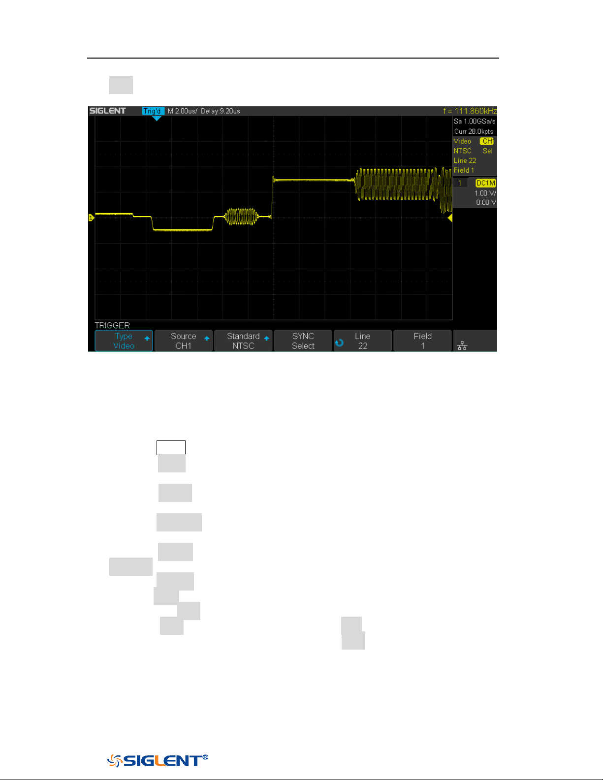
SDS1000X-E&SDS1000X-U User Manual
78
WWW.SIGLENT.COM
Field softkey and then turn the Universal Knob to select 1 and push the knob to
confirm
Figure 34 Video Trigger
To Use Custom Video Trigger
Custom video trigger supports frame rate of 25Hz, 30Hz, 50Hz and 60Hz, and the
line range is available from 300 to 2000. The steps below show how to set custom
trigger.
1. Press the
Setup button on the front panel to enter the TRIGGER function menu.
2. Press the Type softkey; then use the Universal Knob to select Video and push
down the knob to confirm.
3. Press the Source softkey; turn the Universal Knob to select CH1 as the trigger
source, and push down the knob to confirm.
4. Press the Standard softkey; turn the Universal Knob to select Custom, and push
down the knob to confirm.
5. Press the Setting softkey to enter the custom setting function menu. Press the
Interlace softkey; turn the Universal Knob to select the desired value.
6. Press the Of Field softkey; turn the Universal Knob to select the desired value.
7. Press the Sync softkey to enter the TRIG ON menu to set the line and field.
Press the Type softkey to select Select or Any.
If the Type option set to Select, press the Line softkey; turn the Universal
Knob to select the desired value. Press the Field softkey; turn the Universal
Knob to select the desired value.
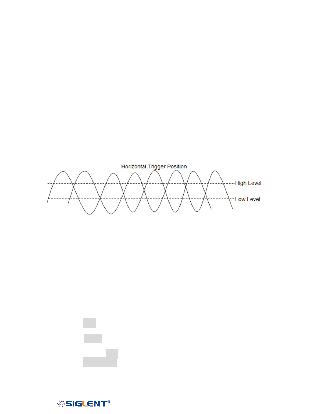
SDS1000X-E&SDS1000X-U User Manual
79
WWW.SIGLENT.COM
Window Trigger
Windows trigger provides a high trigger level and a low trigger level. The
instrument triggers when the input signal passes through the high trigger level or
the low trigger level.
There are two kinds of window types: Absolute and Relative. They have different
trigger level adjustment methods. Under Absolute window type, the lower and the
upper trigger levels can be adjusted respectively via the Level knob; under Relative
window type, adjust the Center value to set the window center; adjust the Delta
value to set the window range, the lower and the upper trigger levels always move
together.
If the lower and the upper trigger levels are both within the waveform
amplitude range, the oscilloscope will trigger on both rising and falling edge.
If the upper trigger level is within the waveform amplitude range while the
lower trigger level is out of the waveform amplitude range, the oscilloscope
will trigger on rising edge only.
If the lower trigger level is within the waveform amplitude range while the
upper trigger level is out of the waveform amplitude range, the oscilloscope
will trigger on falling edge only.
To set window trigger via Absolute window type:
1. Press the Setup button on the front panel to enter the TRIGGER function menu.
2. Press the Type softkey; then use the Universal Knob to select Window and push
down the knob to confirm.
3. Press the Source softkey; turn the Universal Knob to select CH1 or CH2 as the
trigger source.
4. Press the Window Type softkey to select Absolute.
5. Press the Lower Upper softkey to select Lower or Upper trigger level; then turn
the Trigger Level Knob to adjust the position. The trigger level values are
displayed at the upper right corner of the screen.
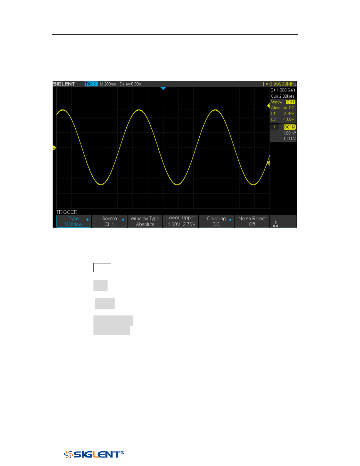
SDS1000X-E&SDS1000X-U User Manual
80
WWW.SIGLENT.COM
The Lower trigger level cannot be upper than the upper trigger level. In the
trigger state message box, L1 means the upper trigger level while L2 means
the lower trigger level.
Figure 35 Absolute Window Trigger
To set window trigger via Relative window type:
1. Press the
Setup button on the front panel to enter the TRIGGER system function
menu.
2. Press the Type softkey; then use the Universal Knob to select Window and push
down the knob to confirm.
3. Press the Source softkey; turn the Universal Knob to select CH1 or CH2 as the
trigger source.
4. Press the Window Type softkey to select Relative.
5. Press the Center Delta softkey to select Center or Delta trigger level mode; then
turn the Trigger Level Knob to adjust the position. The Center and Delta values
are displayed at the upper right corner of the screen.
6. In the trigger state message box, C means Center, the center value of the lower
and upper trigger levels;
D means Delta, the difference between the lower (or
upper) trigger level and the trigger level center.
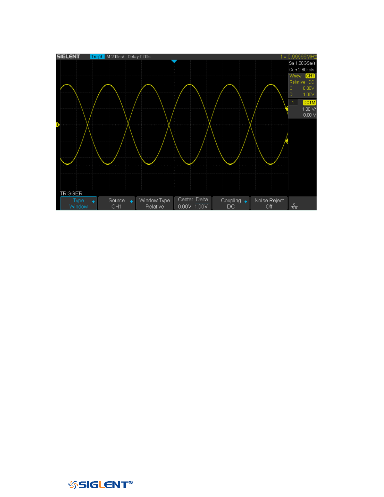
SDS1000X-E&SDS1000X-U User Manual
81
WWW.SIGLENT.COM
Figure 36 Relative Window Trigger
Coupling and noise reject can be set in Window trigger, see the sections "Trigger
Coupling" and "Noise Rejection" for details.
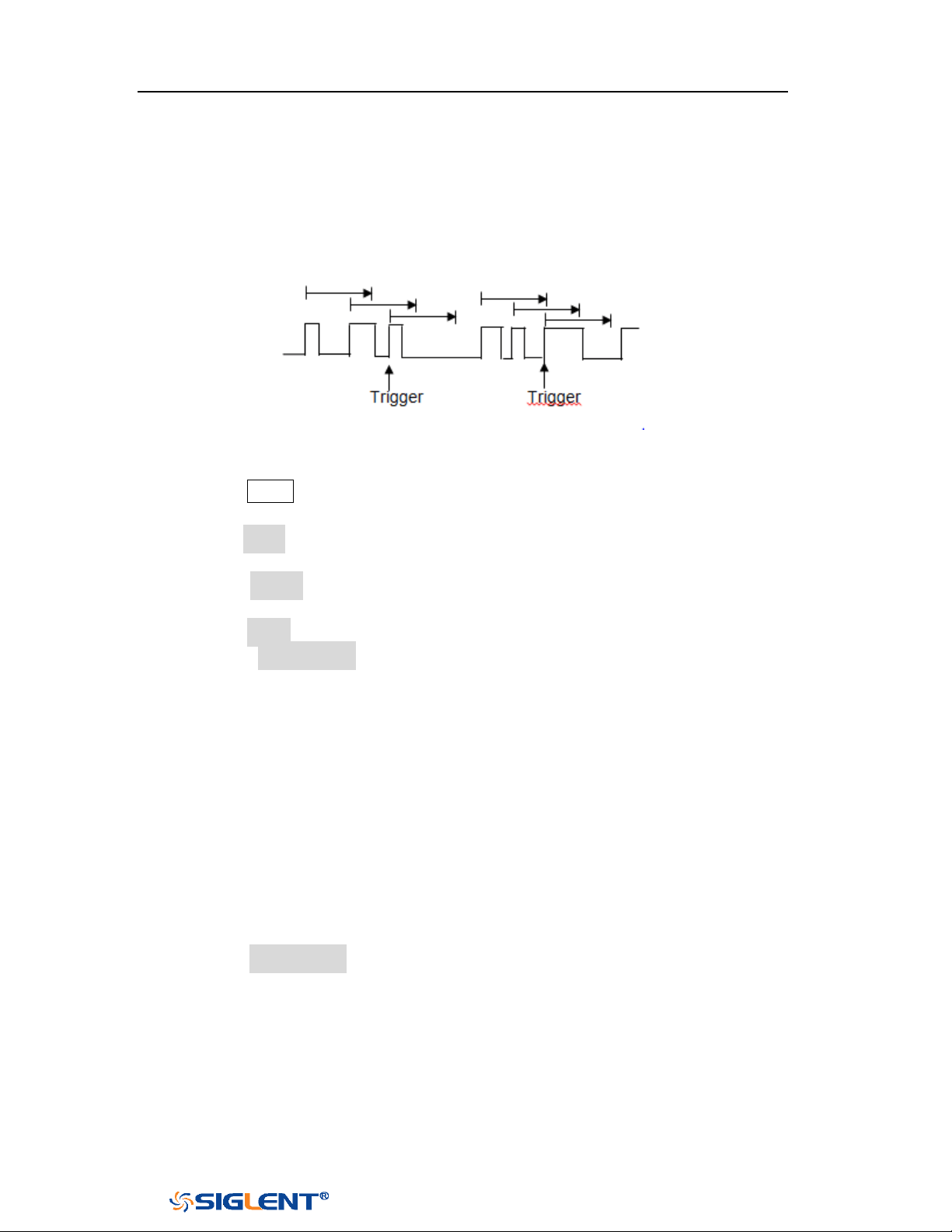
SDS1000X-E&SDS1000X-U User Manual
82
WWW.SIGLENT.COM
Interval Trigger
Trigger when the times difference between the neighboring rising or falling edges
meets the time limit (<=, >=, [--,--], --][--).
To set interval trigger:
1. Press the
Setup button on the front panel to enter the TRIGGER system function
menu.
2. Press the Type softkey; then use the Universal Knob to select Interval and push
down the knob to confirm.
3. Press the Source softkey; turn the Universal Knob to select CH1 or CH2 as the
trigger source.
4. Press the Slope softkey to select rising or falling edge.
5. Press the Limit Range softkey; turn the Universal Knob to select desired
condition.
<= (less than a time value): trigger when the positive or negative pulse
time of the input signal is lower than the specified time value.
>= (greater than a time value): trigger when the positive or negative pulse
time of the input signal is greater than the specified time value.
[--,--] (within a range of time value):trigger when the positive or negative
pulse time of the input signal is greater than the specified lower limit of
time and lower than the specified upper limit of time value.
--][-- (outside a range of time value): trigger when the positive or negative
pulse time of the input signal is greater than the specified upper limit of
time and lower than the specified lower limit of time value.
6. Press the Time Setting softkey (<=, >=, [--,--],--][--), turn the Universal Knob to
select the desired value.

SDS1000X-E&SDS1000X-U User Manual
83
WWW.SIGLENT.COM
Figure 37 Interval Trigger
Coupling and noise reject can be set in interval trigger, see the sections "Trigger
Coupling" and "Noise Rejection" for details.
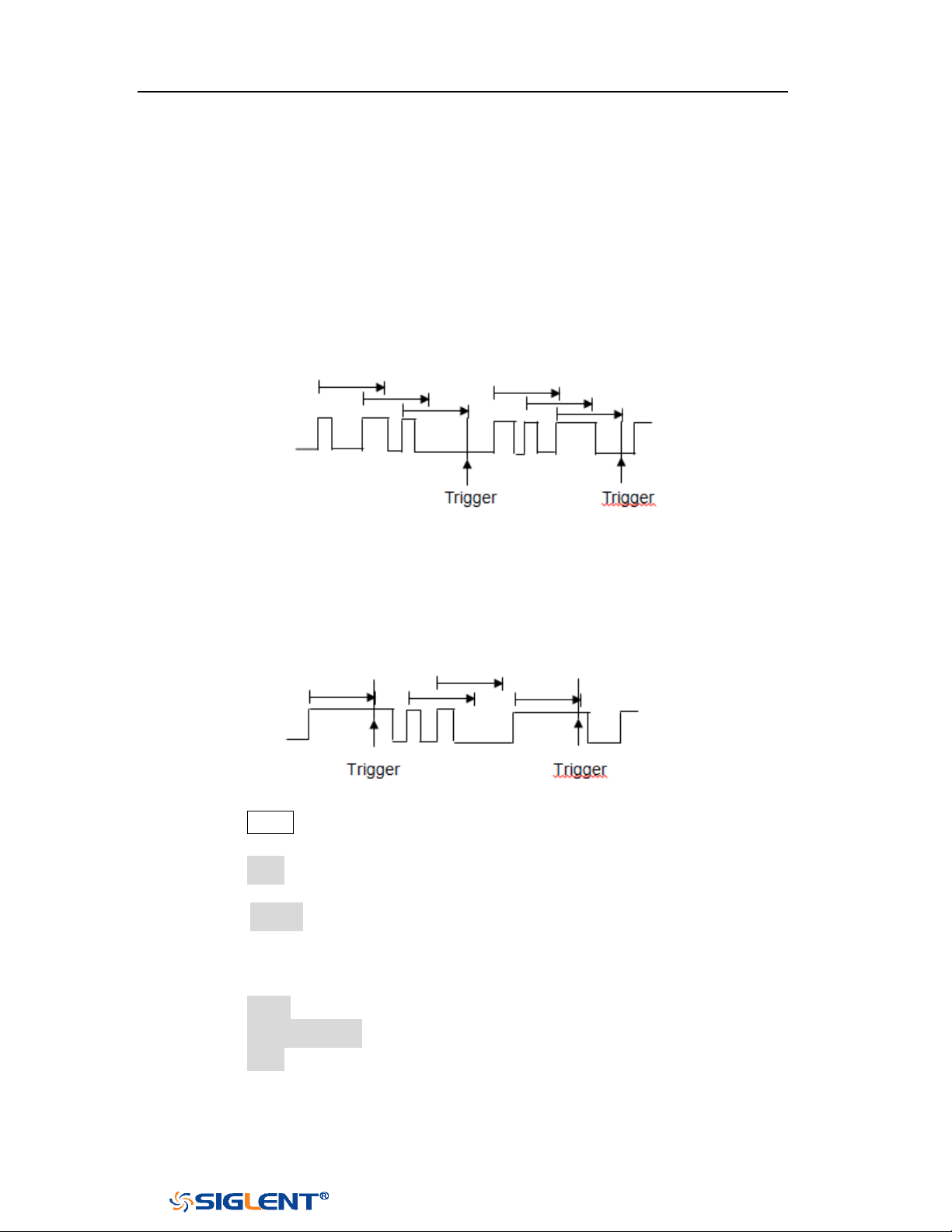
SDS1000X-E&SDS1000X-U User Manual
84
WWW.SIGLENT.COM
Dropout Trigger
Dropout trigger includes two types: edge and state.
Edge
Trigger when the time interval (△T) from when the rising edge (or falling edge) of
the input signal passes through the trigger level to when the neighboring rising
edge (or falling edge) passes through the trigger level is greater than the timeout
time set, as shown in the figure below.
State
Trigger when the time interval (△T) from when the rising edge (or falling edge) of
the input signal passes through the trigger level to when the neighboring falling
edge (or rising edge) passes through the trigger level is greater than the timeout
time set, as shown in the figure below.
To set edge Dropout trigger:
1. Press the Setup button on the front panel to enter the TRIGGER system function
menu.
2. Press the Type softkey; then use the Universal Knob to select Dropout and push
down the knob to confirm.
3. Press the Source softkey; turn the Universal Knob to select CH1 or CH2 as the
trigger source. The current trigger source is displayed at the upper right corner
of the screen. Select channel with signal input as trigger source to obtain
stable trigger.
4. Press the Slope softkey to select rising or falling edge.
5. Press the OverTime Type softkey to select Edge.
6. Press the Time softkey; turn the universal to select the desired value.
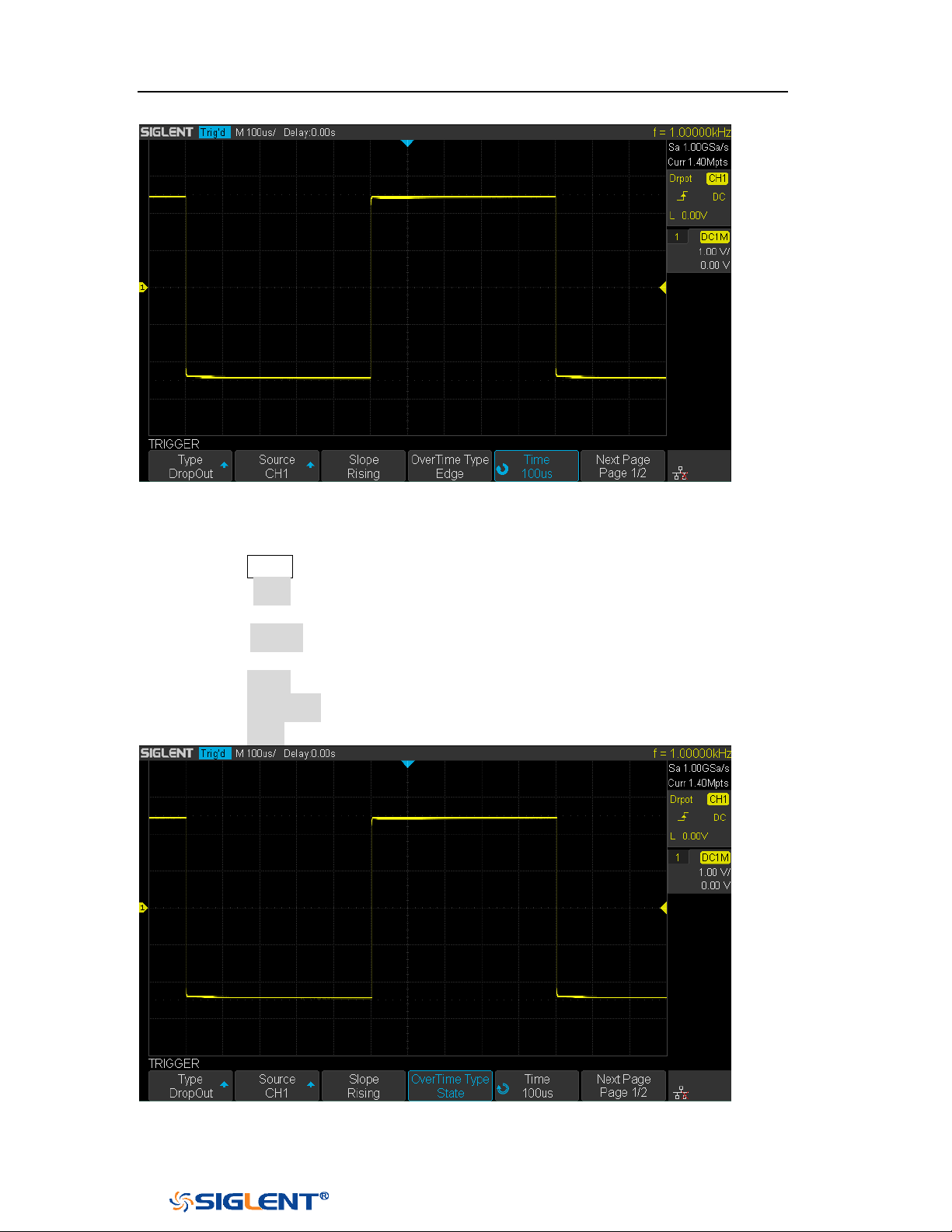
SDS1000X-E&SDS1000X-U User Manual
85
WWW.SIGLENT.COM
Figure 38 Edge Dropout Trigger
To set state Dropout trigger:
1. Press the Setup button to enter the TRIGGER system function menu.
2. Press the Type softkey; then turn the Universal Knob to select Dropout and
push down the knob to confirm.
3. Press the Source softkey; turn the Universal Knob to select CH1 or CH2 as the
trigger source.
4. Press the Slope softkey to select rising or falling edge.
5. Press the OverTime Type softkey to select State.
6. Press the Time softkey; turn the Universal Knob to select the desired value.
Figure 39 State Dropout Trigger

SDS1000X-E&SDS1000X-U User Manual
86
WWW.SIGLENT.COM
Coupling and noise reject can be set in dropout trigger, see the sections "Trigger
Coupling" and "Noise Rejection" for details.
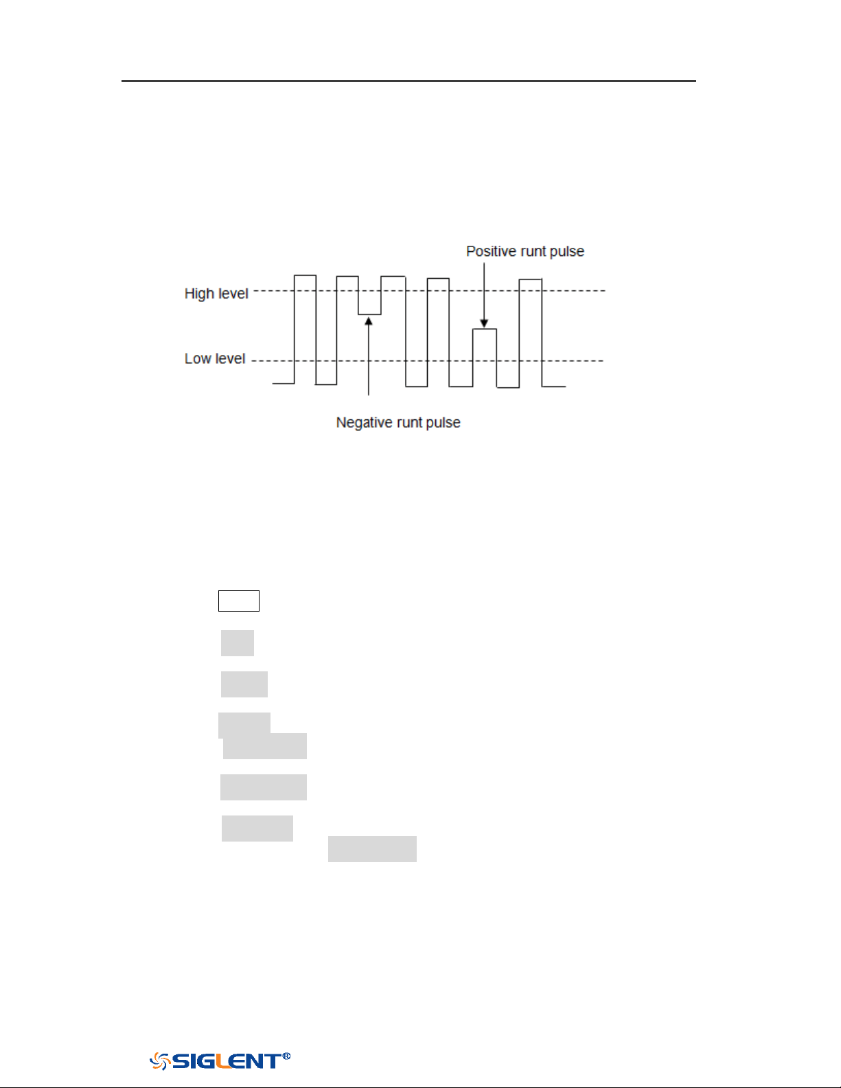
SDS1000X-E&SDS1000X-U User Manual
87
WWW.SIGLENT.COM
Runt Trigger
The Runt trigger looks for pulses that cross one threshold but not another as shown
in the picture below.
A positive runt pulse across through a lower threshold but not an upper
threshold.
A negative runt pulse across through an upper threshold but not a lower
threshold.
To trigger on runt pulse:
1. Press the
Setup button on the front panel to enter the TRIGGER system function
menu.
2. Press the Type softkey; then turn the Universal Knob to select Runt and push
down the knob to confirm.
3. Press the Source softkey; turn the Universal Knob to select CH1 or CH2 as the
trigger source.
4. Press the Polarity softkey to select Positive or Negative pulse to trigger.
5. Press the Limit Range softkey; turn the Universal Knob to select the desired
condition (<=, >=, [--,--] or --][--).
6. Press the Time Setting softkey, and then turn the Universal Knob to select the
desired value.
7. Press the Next Page softkey to enter the second page of the TRIGGER system
function menu. Press the Lower Upper softkey to select Lower or Upper trigger
level, and the turn the
Universal Knob to set the position.
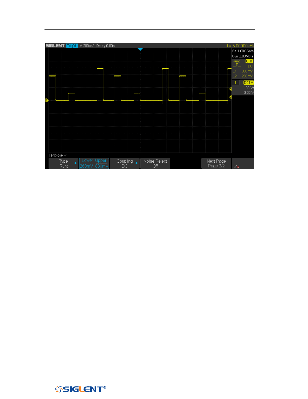
SDS1000X-E&SDS1000X-U User Manual
88
WWW.SIGLENT.COM
Figure 40 Runt Trigger
Coupling and noise reject can be set in runt trigger, see the sections "Trigger
Coupling" and "Noise Rejection" for details.
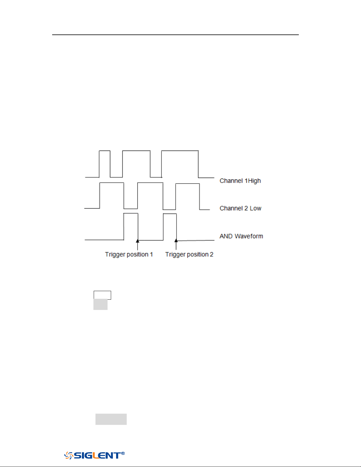
SDS1000X-E&SDS1000X-U User Manual
89
WWW.SIGLENT.COM
Pattern Trigger
The Pattern trigger identifies a trigger condition by looking for a specified pattern.
The pattern trigger can be expanded to incorporate delays similar to other triggers.
Pattern durations are evaluated using a timer. The timer starts on the last edge
that makes the pattern “true”. Potential triggers occur on the first edge that
makes the pattern false, provided that the time qualifier criterion has been met.
The oscilloscope provides 4 patterns: logical AND, OR, NAND and NOR combination
of the channels. Each channel can set to low, high or invalid.
Do the following steps to set pattern trigger:
1. Press the
Setup button on the front panel to enter the TRIGGER function menu.
2. Press the Type softkey; turn the Universal Knob to select Pattern, and then push
down the knob to confirm.
3. Press each channel softkey to select Invalid, High or Low.
Low sets the pattern to low on the selected channel. A low is a voltage
level that is less than the channel's trigger level or threshold level.
High sets the pattern to high on the selected channel. A high is a voltage
level that is greater than the channel's trigger level or threshold level.
Don’t care sets the pattern to don't care on the selected channel. Any
channel set to don't care is ignored and is not used as part of the pattern.
However, if all channels in the pattern are set to Don’t care, the
oscilloscope will not trigger.
Adjust the trigger level for the selected analog channel by turning the
Trigger Level knob. Don’t care doesn’t need to set trigger level.
4. Press the Next Page softkey to enter the second page of the pattern trigger
menu.
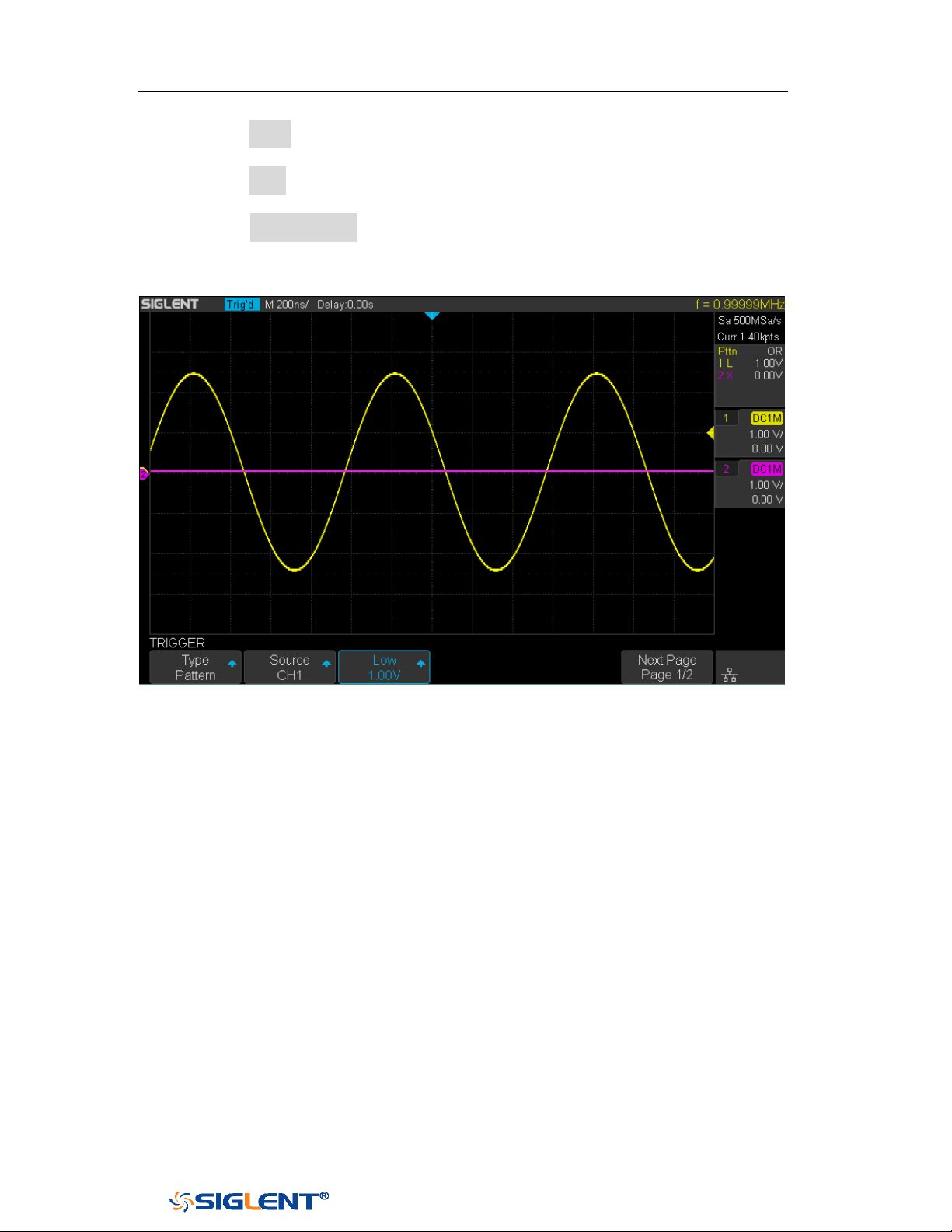
SDS1000X-E&SDS1000X-U User Manual
90
WWW.SIGLENT.COM
5. Press the Logic softkey and then turn the Universal Knob to select the desired
logic combination AND, OR, NAND or NOR.
6. Press the Time softkey; then turn the Universal Knob to select the desired time
value.
7. Press the Holdoff Close softkey to turn on the Holdoff function; then turn the
Universal Knob to select the desired value.
Figure 41 Pattern Trigger
Holdoff can be set in pattern trigger, see the sections "Trigger Holdoff" for details.

SDS1000X-E&SDS1000X-U User Manual
91
WWW.SIGLENT.COM
Serial Trigger and Decode
The oscilloscope provides I2C, SPI, UART, CAN and LIN serial trigger and decode.
This chapter introduces the method of triggering and decoding these serial signals
in details.
The contents of this chapter:
I2C Trigger and Decode
SPI Trigger and Decode
UART Trigger and Decode
CAN Trigger and Decode
LIN Trigger and Decode
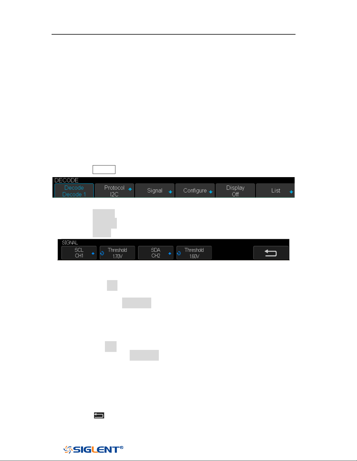
SDS1000X-E&SDS1000X-U User Manual
92
WWW.SIGLENT.COM
I2C Trigger and Serial Decode
Please in order of “
Setup for I2C Signals”, “I2C Trigger” and “I2C Serial
Decode” to trigger and decode the signals.
Setup for I2C Signals
Setting the I2C (Inter-IC bus) signal includes two steps: connecting the serial data
signal (SDA) and serial clock signal (SCK) to oscilloscope, specifying the threshold
voltage of each input signal.
1. Press the
Decode key to enter the DECODE function menu as Figure 42 shows.
Figure 42 I2C DECODE Menu
2. Press the Decode softkey and select the desired slot (Decode1 or Decode2).
3. Press the Protocol softkey and then select I2C by turning Universal Knob.
4. Press the Signal softkey to enter the SIGNAL menu as Figure 43 shows.
Figure 43 I2C SIGNAL Menu
5. Set SCL (I2C’s clock signal):
a. Press the SCL softkey to select the channel that is connected to the I2C
clock signal.
b. Press the first Threshold softkey to set the I2C clock signal’s threshold
voltage level by Universal Knob. The threshold voltage level is for
decoding, and it will be regard as the trigger voltage level when set the
trigger type to serial.
6. Set SDA (I2C’s data signal):
a. Press the SDA to select the channel that is connected to the I2C data signal.
b. Press the second Threshold softkey to set the I2C data signal’s threshold
voltage level by
Universal Knob. The threshold voltage level is for
decoding, and it will be regard as the trigger voltage level when set the
trigger type to serial.
(Tips: SDA should keep stable during the whole high clock cycle, otherwise it
will be interpreted as a start or stop condition (data transitioning while the
clock is high))
7. Press the softkey to return previous menu.
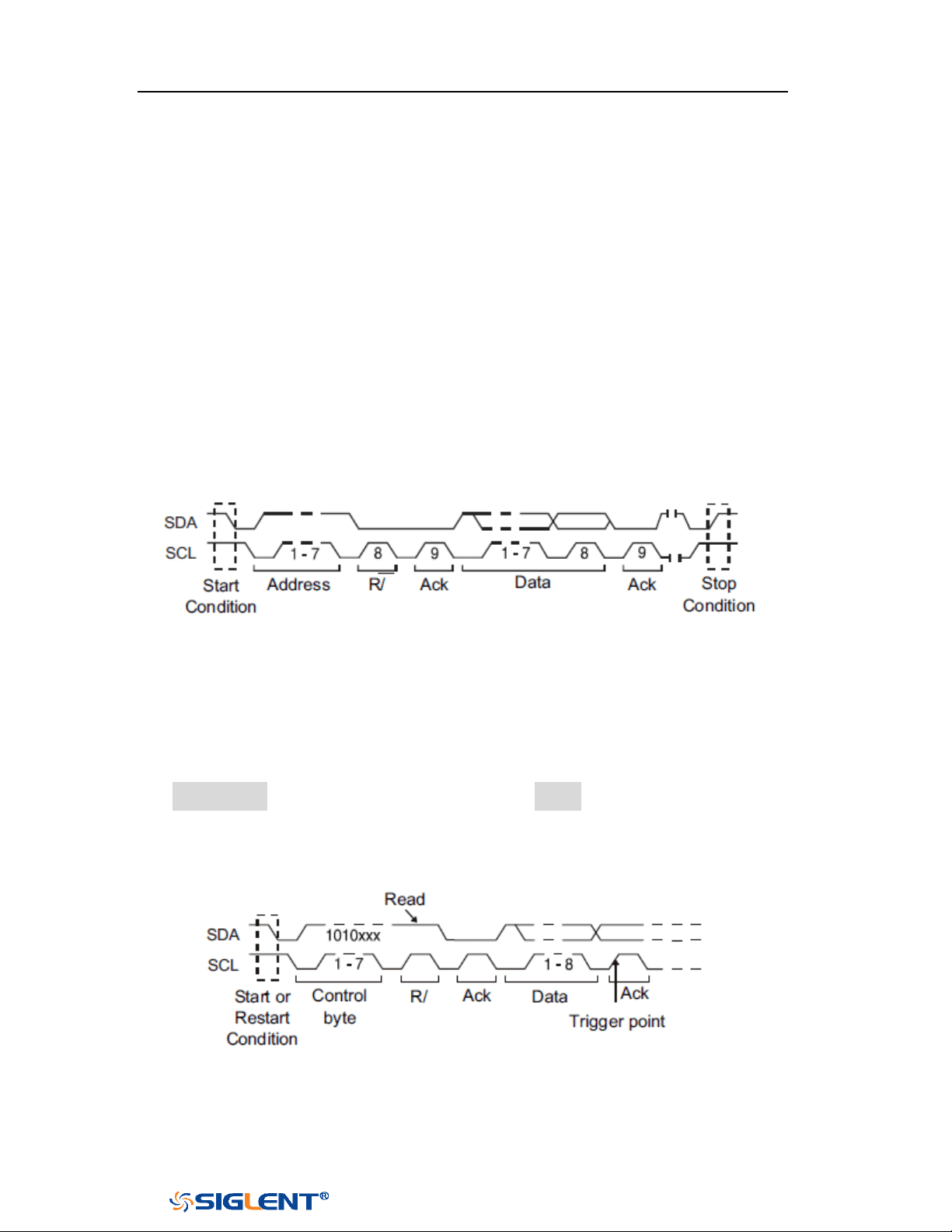
SDS1000X-E&SDS1000X-U User Manual
93
WWW.SIGLENT.COM
I2C Trigger
This part introduces the nine kinds of trigger conditions (Start, Stop, Restart, No Ack,
EEPROM, 7 Addr&Data, 10 Addr&Data and Data Length) and the methods of setting
them.
Trigger Conditions
Start Condition— the oscilloscope will be triggered when SDA signal transitions
from high to low while the SCL clock is high. If it is chosen as the condition of
trigger (including frame triggers), a restart will be treated as a “Start
condition”.
Stop Condition— the oscilloscope will be triggered when SDA transitions from
low to high while the SCL is high.
Restart— the oscilloscope will be triggered when another “Start condition”
occurs before a “Stop condition”.
No Ack— the oscilloscope will be triggered when SDA data is high during any
SCL’s ACK bit.
EEPROM — the trigger searches for EEPROM control byte (the value is 1010xxx)
on the SDA bus. And there is a Read bit and an ACK bit behind EEPROM. Using
Limit Range softkey to set the qualifier and Data1 softkey to set the data’s
value. If EEPROM’s data is greater(less, equal) than Data1, the oscilloscope will
be triggered at the edge of ACK bit behind Data byte. It’s unnecessary that the
Data byte musts follow the EEPROM.
7 Address & Data — the oscilloscope will be triggered when the following
conditions are satisfied.
The address’s length must be 7 bits and the address’s value is the same as
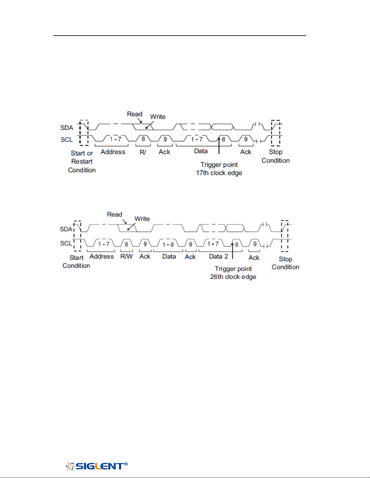
SDS1000X-E&SDS1000X-U User Manual
94
WWW.SIGLENT.COM
set value.
If you have set either Data1’s or Data2’s value, and the signal has a data is
the same as that value. If you have set both Data1’s and Data2’s value, the
signal should has two consecutive data, the first data’s value is Data1,
second data value is Data2.
(Note: If the data’s value is 0xXX, any data value will be matched)
10 Address & Data — the oscilloscope will be triggered when the following
conditions are satisfied.
The address’s length must be 10 bits and the address’s value is the same
as set value.
If you have set either Data1’s or Data2’s value, and the signal has a data is
the same as that value. If you have set both Data1’s and Data2’s value, the
signal should has two consecutive data, the first data’s value is Data1,
second data value is Data2.
(
Note: If the set value is 0xXX, any data value will be matched)
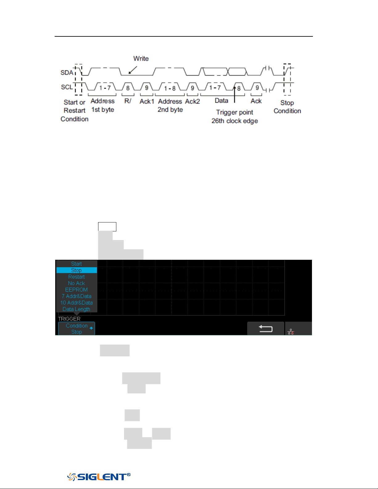
SDS1000X-E&SDS1000X-U User Manual
95
WWW.SIGLENT.COM
Data Length — When SDA data’s length is equal to the value of Byte Length
and address’s length is the same as set value, the oscilloscope will be
triggered. Byte length is in the range of 1 to 12 bits.
Operation Steps
1. Press the Setup to enter the TRIGGER function menu.
2. Press the Type and select Serial.
3. Press the Protocol and select I2C.
4. Press the Trigger Setting softkey.
Figure 44 I2C TRIGGER Menu
5. Press the Condition softkey and turn the Universal Knob to select the trigger
condition:
If you select the EEPROM condition:
a. Press the Limit Range softkey to set the qualifier (=, < or >).
b. Press the Data1 softkey and set its value by turning the Universal
Knob.
If you select 7 Addr & Data or 10 Addr & Data condition:
a. Press the Addr softkey and turn the Universal Knob to select the 7- bit
or 10- bit device address.
b. Press the Data1 or Data2 softkey and set the value about them.
c. Press the R/W bit softkey and select write-frame or read-frame to

SDS1000X-E&SDS1000X-U User Manual
96
WWW.SIGLENT.COM
trigger the oscilloscope.
(Tips: If device address is 7-bit, the value of address is in range of 0x00 to
0x7F. If device’s address is 10-bit, the value of address is in range of 0x00
to 0x3FF.)
If you select the Data Length condition:
a. Press the Address to set the SDA address length 7bit or 10 bit.
b. Press the Byte Length softkey and set the byte length by Universal
Knob. The range of the Byte Length is 1 to 12.

SDS1000X-E&SDS1000X-U User Manual
97
WWW.SIGLENT.COM
I2C Serial Decode
After completing the setup of I2C signal and trigger, we will decode I2C signals.
Operation steps as follows.
1. Press Decode→ Decode. Select one of the options from the Decode1 and
Decode2.
2. Press the Display and select On to display the result of decoding.
3. Press the Configure to turn on or off the read or write bit.
4. Press the List to enter the LIST function menu.
Press the Display and choose the same options as the first step.
Press the Scroll and turn the Universal Knob to view all frames.
Press the Lines and set the number of lines by Universal Knob. The range
of the lines is 1 to 7.
When a packet of data is long, all decoded data are not displayed. Turn on
the Long Data to display the complete data.
Users can export the result list of the package to the external USB storage
device in csv format (only when the USB flash disk is detected). Saving the
data (*.csv) is similar to the operation of setup files, see the section
"External save and recall" for details.
5. Press the Format to change the character encoding format of the decoding’s
result.
6. Press the Copy Setting to enter the COPY function menu to synchronize the
corresponding bus configuration and trigger configuration.
7. Press the Tips Info to turn on or off the decoding limit prompt. When the
decoding frame number reaches the maximum, it will pop up "Decoding to
maximum frame number limitation!"
Interpreting I2C Decode
The frames of decoding result:
The address value is displayed at the beginning of a frame. The write address
is displayed in green, and read address in yellow.
W/R bit is represented by (W) and (R), following the address value.
The data value is displayed in white.
"~A" after a data or address bits indicates no acknowledgement. For example,
DB~A.
Indicates there is not enough space on the display to show the complete
content of a frame, and some content is hidden.
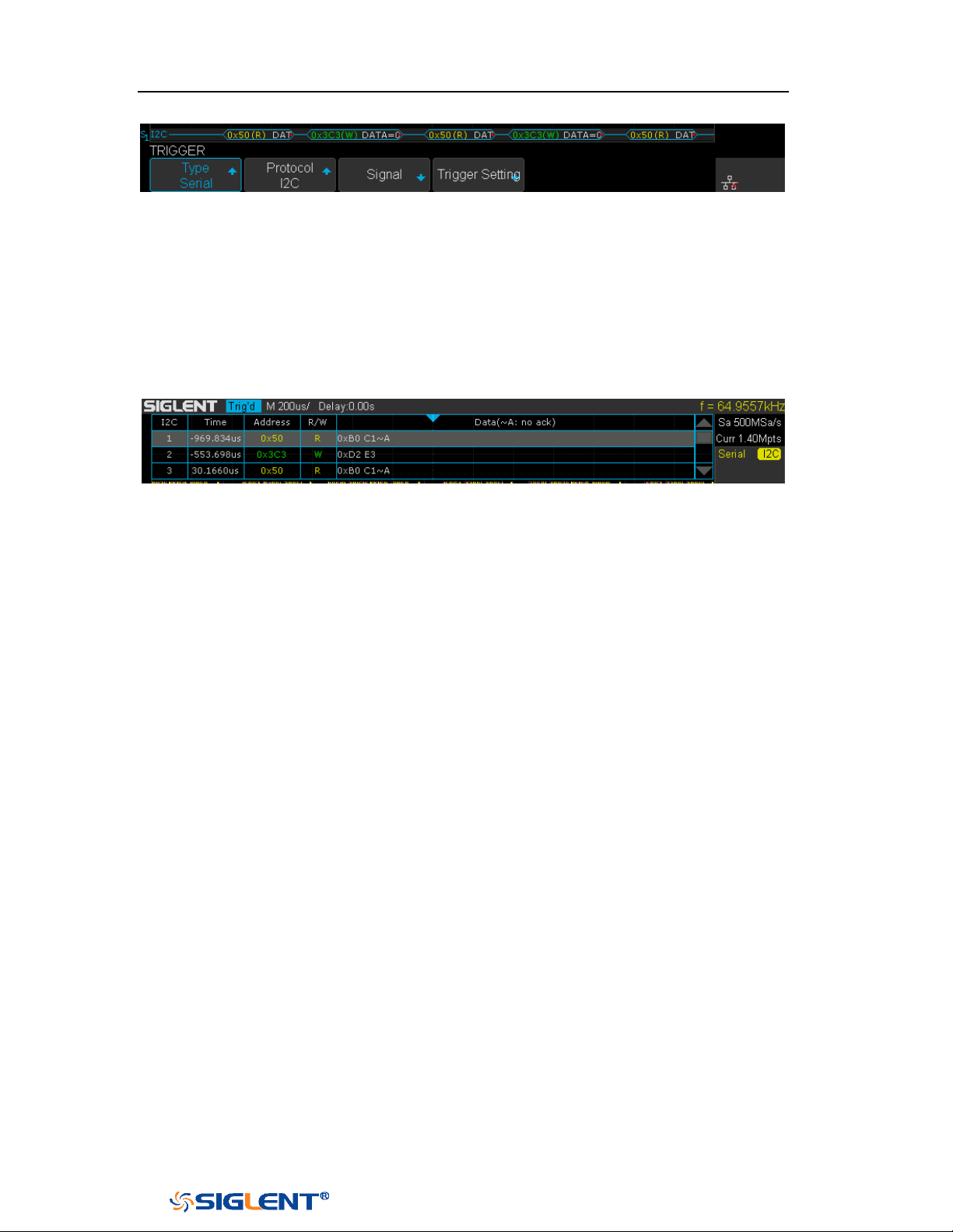
SDS1000X-E&SDS1000X-U User Manual
98
WWW.SIGLENT.COM
Figure 45 I2C Decode Bus Display
The lists of decoding result:
Time — the horizontal displacement between current frame and trigger
position.
Address — the address of a frame.
R/W — the type of a frame (write or read).
Data — the value of data.
Figure 46 I2C Decode List Display
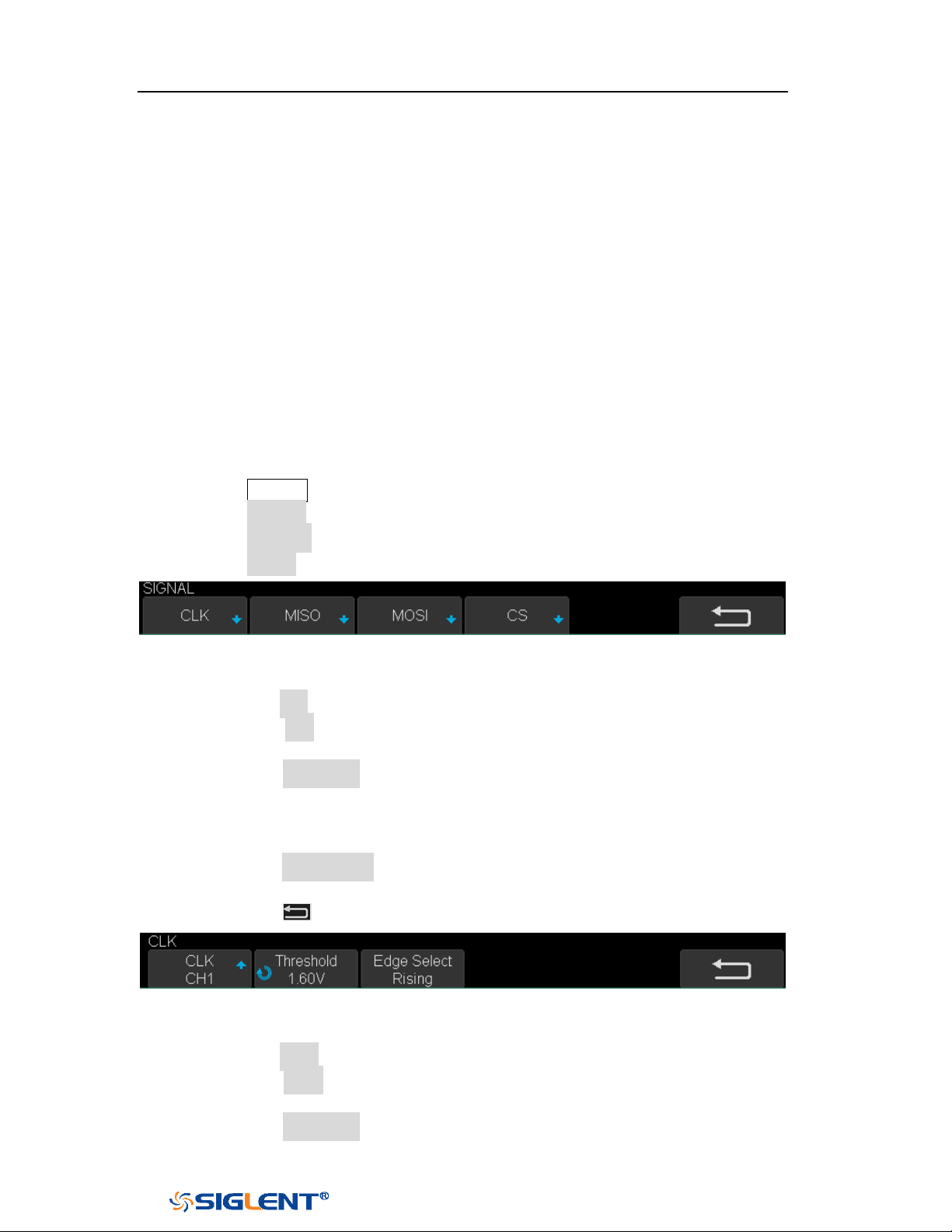
SDS1000X-E&SDS1000X-U User Manual
99
WWW.SIGLENT.COM
SPI Trigger and Serial Decode
Please in order of “
Setup for SPI Signals”, “SPI Trigger” and “SPI Serial
Decode” to trigger and decode the signals.
Setup for SPI Signals
Setting the SPI (Serial Peripheral Interface) signal includes two steps: connecting
the CLK, MISO, MOSI and CS signals to oscilloscope; specifying the parameters of
each input signal.
1. Press the
Decode key to enter the DECODE function menu.
2. Press the Decode softkey and select the desired slot (Decode1 or Decode2).
3. Press the Protocol softkey and then select SPI by turning Universal Knob.
4. Press the Signal softkey to enter the SIGNAL menu as Figure 47 shows.
Figure 47 SPI SINGAL Menu
5. Set CLK (clock signal):
a. Press the CLK softkey to enter CLK menu.
b. Press the CLK softkey to select the channel that is connected to the SPI
clock signal.
c. Press the Threshold softkey to set the SPI clock signal’s threshold voltage
level by Universal Knob. The threshold voltage level is for decoding, and it
will be regard as the trigger voltage level when set the trigger type to
serial.
d. Press the Edge Select softkey to set the oscilloscope will samples at clock
signal’s rising edge or falling edge.
e. Press the softkey to return previous menu.
Figure 48 SPI CLK Menu
6. Set MISO:
a. Press the MISO softkey to enter the MISO menu.
b. Press the MISO softkey to select the channel that is connected to the SPI
MISO signal.
c. Press the Threshold softkey to set the SPI MISO signal’s threshold voltage
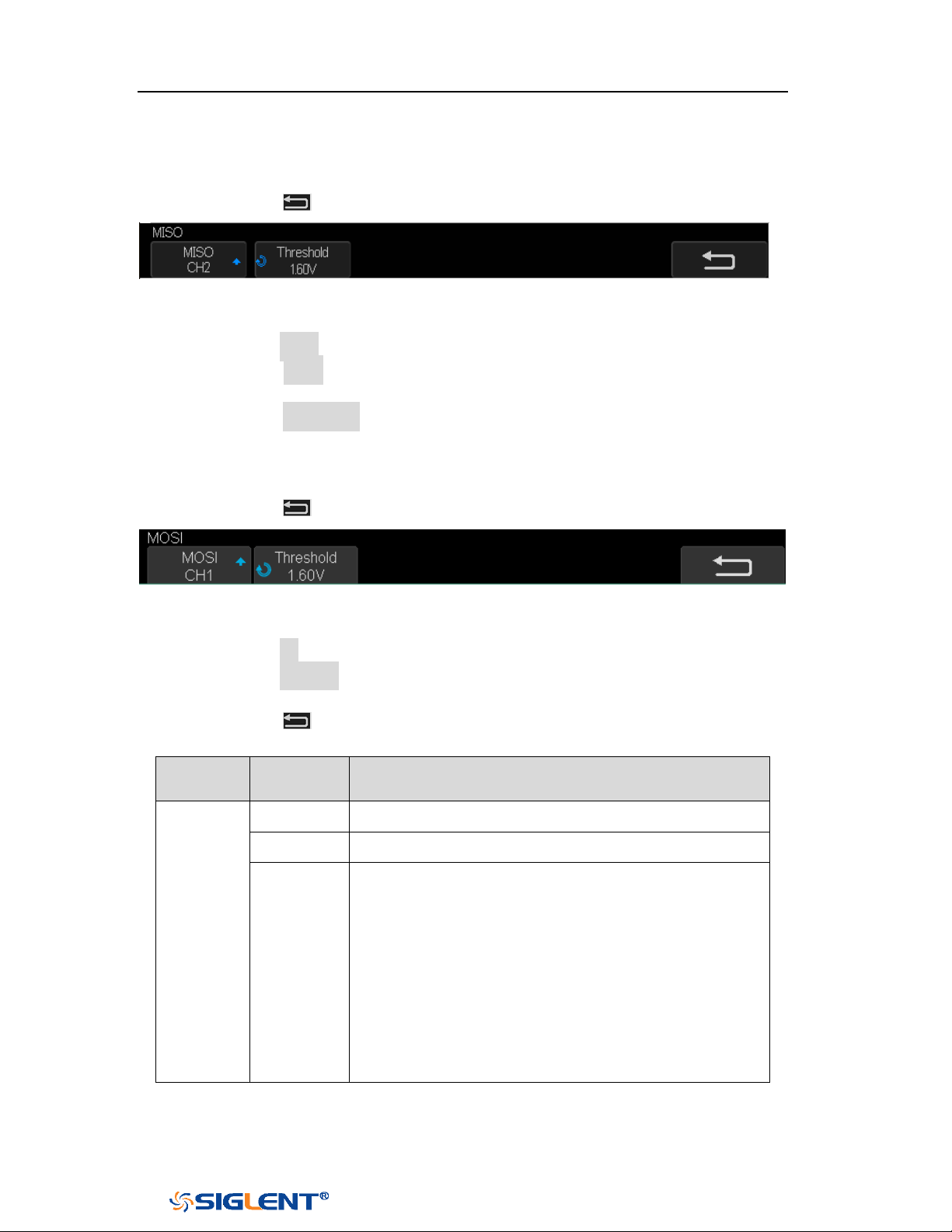
SDS1000X-E&SDS1000X-U User Manual
100
WWW.SIGLENT.COM
level by Universal Knob. The threshold voltage level is for decoding, and it
will be regard as the trigger voltage level when set the trigger type to
serial.
d. Press the softkey to return previous menu.
Figure 49 MISO Menu
7. Set MOSI:
a. Press the MOSI softkey to enter the MOSI menu.
b. Press the MOSI softkey to select the channel that is connected to the SPI
MOSI signal.
c. Press the Threshold softkey to set the SPI MOSI signal’s threshold voltage
level by Universal Knob. The threshold voltage level is for decoding, and it
will be regard as the trigger voltage level when set the trigger type to
serial.
d. Press the softkey to return previous menu.
Figure 50 MOSI Menu
8. Set CS:
a. Press the CS softkey to enter the MOSI menu.
b. Press the Cs Type softkey to select the chip select type.
c. Modify the Cs type’s value.
d. Press the
softkey to return previous menu.
Function
Menu
Settings
Explanation
CS Type
~CS
low voltage level of CS signal is available
CS
high voltage level of CS signal is available
CLK
Timeout
If the time between two edges of clock signal is less
than (or equal to) the value of timeout, the signal
between the two edges is treat as a frame. The
range of clock timeout is 100ns-5ms.
This setting is suitable for case where CS signal is
not connected, or the number of oscilloscope
channels is insufficient (such as 2-channel
oscilloscopes).
Table 1 Menu Explanations of the CS Type Parameters
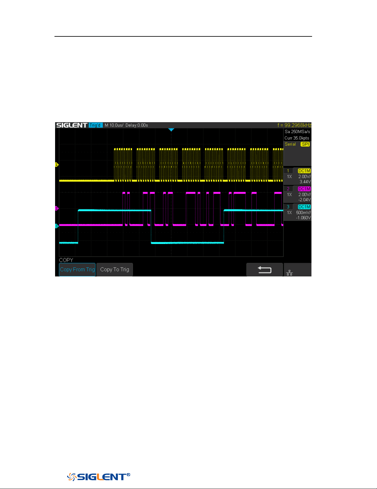
SDS1000X-E&SDS1000X-U User Manual
101
WWW.SIGLENT.COM
Example:
Connect the data, CLK and ~CS signals of a SPI bus respectively to C1, C2 and C3.
Data width = 8-bit, Bit order = MSB, CS polarity = ~CS, and 12 data bytes are
transmitted in one frame.
In the SPI trigger signal menu, set the source and threshold of CLK, MISO and CS
signals, then copy the trigger settings to decoding. Adjust the timebase, so that
there is a falling edge on CS signal shown in the screen:
When the CS type is set to Clock Timeout, the clock idle time between frames is T3,
the clock period is T1, then set the timeout to a value between T1 and T3:

SDS1000X-E&SDS1000X-U User Manual
102
WWW.SIGLENT.COM
If the data width is set to be greater than 8 bits (such as 16 bits), the clock idle time
between 8-bit data packets T2, and then set the timeout time to a value between
T1/2+T2 and T3.
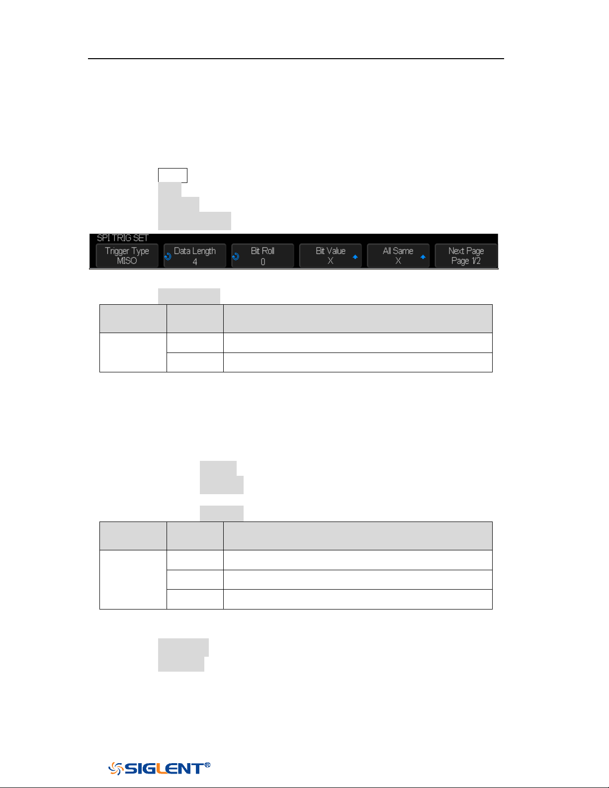
SDS1000X-E&SDS1000X-U User Manual
103
WWW.SIGLENT.COM
SPI Trigger
This part will provide a brief introduction and description for the operation of the
SPI trigger.
1. Press the Setup button to enter the TRIGGER function menu.
2. Press the Type and select Serial.
3. Press the Protocol and select SPI.
4. Press the Trigger Setting softkey.
Figure 51 SPI TRIG SET Menu
5. Press the Trigger Type softkey to select the trigger condition.
Function
Menu
Settings
Explanation
Trigger
Type
MISO
Master-In, Slave-Out
MOSI
Master-Out, Slave-In
Table 2 Menu Explanations of the SPI trigger type
6. Press the Data Length softkey, and turn the Universal Knob to set the length of
a data. The range of data length is 4 to 96 bits.
7. Set the value of the trigger data.
Set the value of a bit:
a. Press the Bit Roll softkey to select a bit in data.
b. Press the Bit Value softkey to set the value of the selected bit.
Set the value of all bits:
a. Press the All Same softkey to set the value of all bits.
Function
Menu
Settings
Explanation
Bit Value
0
High voltage level
1
Low voltage level
X
Don’t care the voltage level
Table 3 Menu Explanations of the SPI Bit value
8. Press the Next Page softkey.
9. Press the Bit Order softkey to set the bit order (MSB or LSB).
SDS1000X-E&SDS1000X-U User Manual
104
WWW.SIGLENT.COM
SPI Serial Decode
After completing the setup of SPI signal and trigger, we will decode SPI signals.
Operation steps as follows.
1. Press Decode → Decode. Select one of the options from the Decode1 and
Decode2.
2. Press the Configure to set the bitstream format and bits (4-32 bits)
3. Press the Display and select On to display the result of decoding.
4. Press the Configure to set bit order and data length.
5. Press the List to enter the LIST function menu.
Press the Display and choose the same options as the first step.
Press the Scroll and turn the Universal Knob to view all frames.
Press the Lines and set the number of lines by Universal Knob. The range
of the lines is 1 to 7.
Users can export the result list of the package to the external USB storage
device in csv format (only when the USB flash disk is detected). Saving the
data (*.csv) is similar to the operation of setup files, see the section
"External save and recall" for details.
6. Press the Format to change the character encoding format of the decoding’s
result.
7. Press the Copy Setting to enter the COPY function menu to synchronize the
corresponding bus configuration and trigger configuration.
8. Press the Tips Info to turn on or off the decoding limit prompt. When the
decoding frame number reaches the maximum, it will pop up "Decoding to
maximum frame number limitation!"
Interpreting SPI Decode
The frames of decoding result:
The data values are displayed in frames and are shown in white. Support 4~96
bit data display.
MISO — the decoding result of “Master-In, Slave-Out” line.
MOSI —the decoding result of “Master-Out, Slave-In” line.
Indicates there is not enough space on the display to show the complete
content of a frame, and some content is hidden.
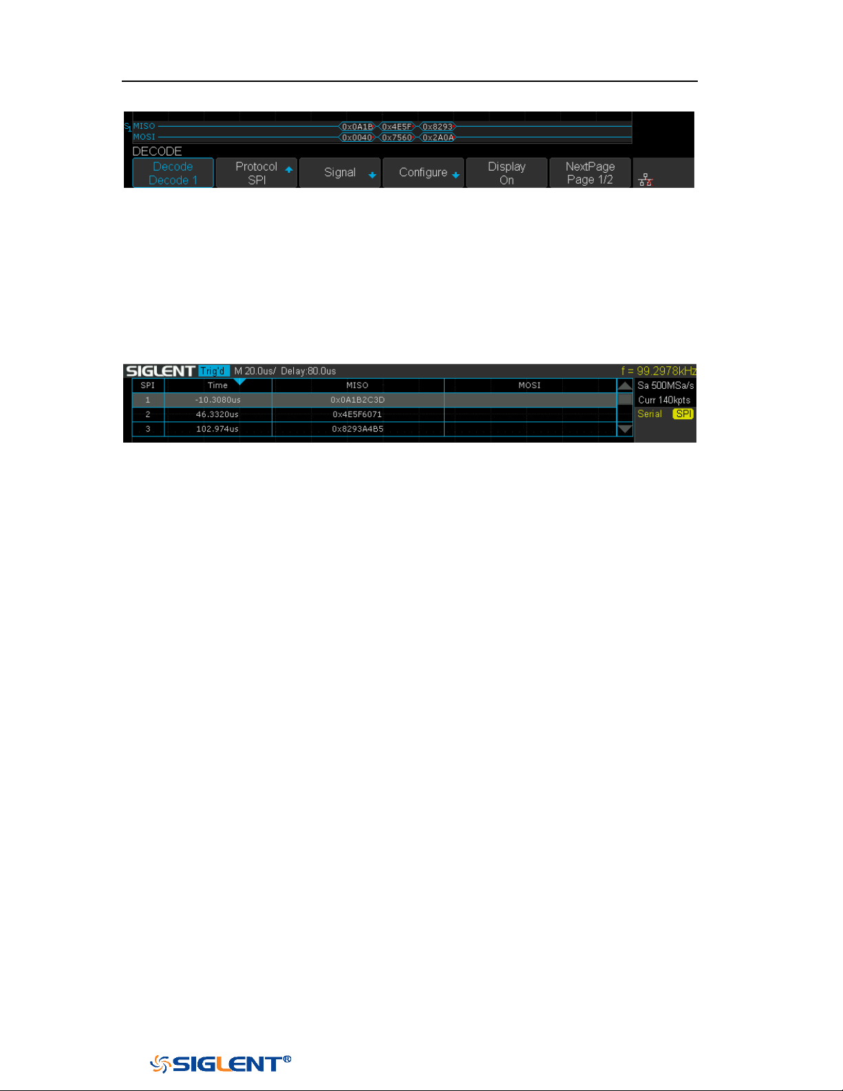
SDS1000X-E&SDS1000X-U User Manual
105
WWW.SIGLENT.COM
Figure 52 SPI Decode Bus Display
The lists of decoding result:
Time — the horizontal displacement between current frame and trigger
position.
MISO — the decoding result of “Master-In, Slave-Out” line.
MOSI —the decoding result of “Master-Out, Slave-In” line.
Figure 53 SPI Decode List Display
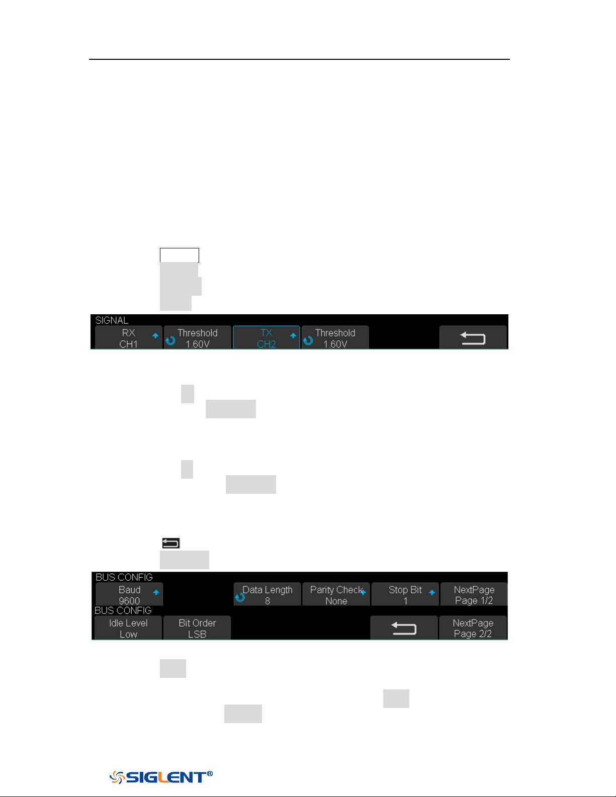
SDS1000X-E&SDS1000X-U User Manual
106
WWW.SIGLENT.COM
UART Trigger and Serial Decode
Please in order of “
Setup for UART Signals”, “UART Trigger” and “UART Serial
Decode” to trigger and decode the signals.
Setup for UART Signals
1. Press the Decode key to enter the DECODE function menu.
2. Press the Decode softkey and select the desired slot (Decode1 or Decode2).
3. Press the Protocol softkey and then select UART by turning Universal Knob.
4. Press the Signal softkey to enter the SIGNAL menu as below shows.
Figure 54 UART SIGNAL Menu
5. Set RX:
a. Press the RX to select the channel that is connected to the RX signal.
b. Press the first Threshold key to set the RX signal’s threshold voltage level
by Universal Knob. The threshold voltage level is for decoding, and it will
be regard as the trigger voltage level when set the trigger type to serial.
6. Set TX:
a. Press the TX to select the channel that is connected to the TX signal.
b. Press the second Threshold key to set the TX signal’s threshold voltage
level by Universal Knob. The threshold voltage level is for decoding, and it
will be regard as the trigger voltage level when set the trigger type to
serial.
7. Press the softkey to return previous menu.
8. Press the Configure softkey to enter BUS CONFIG menu.
Figure 55 BUS CONFIG Menu
9. Press the Baud softkey to set baud rate.
The baud rate can be set as predefined value.
If the desired baud rate is not listed, press the Baud and select custom
option, press the Custom and turn the Universal Knob to set the desired
baud rate.

SDS1000X-E&SDS1000X-U User Manual
107
WWW.SIGLENT.COM
10. Press the Data Length softkey and set byte bits (5-8) by Universal Knob.
11. Press the Parity Check softkey to set the type of parity check (Even, Odd, Mark,
Space or None).
12. Press the Stop Bit softkey to set the length of stop bit (1, 1.5 or 2 bits).
13. Press the Next Page softkey.
14. Press the Bit Order softkey to select the bit order (LSB or MSB).
15. Press the Idle Level softkey to set the idle level (LOW or HIGH).
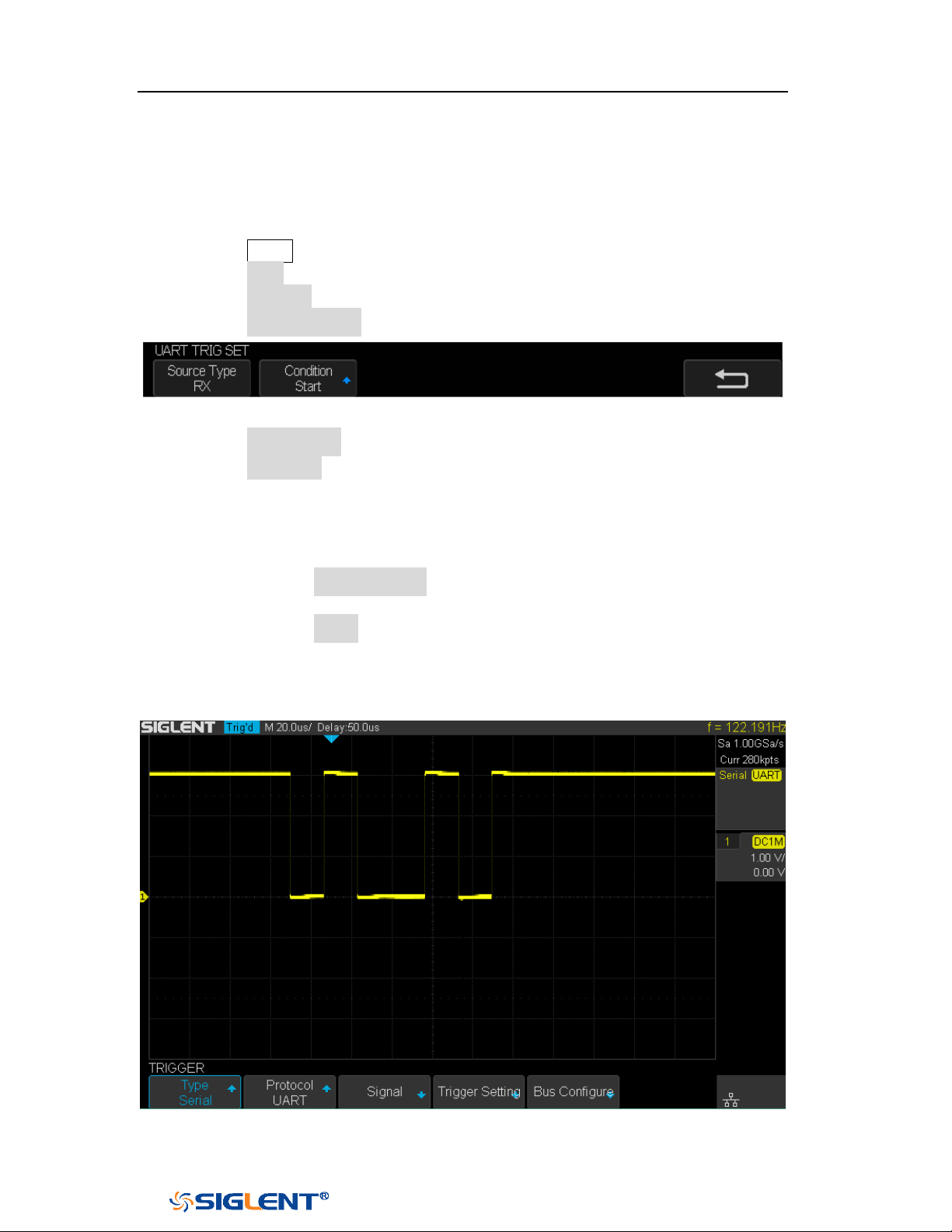
SDS1000X-E&SDS1000X-U User Manual
108
WWW.SIGLENT.COM
UART Trigger
This part shows a brief introduction and description for the operation of the UART
trigger.
1. Press the Setup button to enter the TRIGGER function menu.
2. Press the Type and select Serial.
3. Press the Protocol and select UART.
4. Press the Trigger Setting softkey to enter UART TRIG SET menu.
Figure 56 UART TRIG SET Menu
5. Press the Source Type softkey to select the source of trigger (RX or TX).
6. Press the Condition softkey and set up the desired trigger condition:
Start — the oscilloscope will be triggered at the position of start bit.
Stop —the oscilloscope will be triggered at the position of stop bits.
Data — the oscilloscope will be triggered when found a byte which is
equal to (greater or less than) the specified data.
a. Press the Compare Type softkey and choose an equality qualifier (>, <
or =).
b. Press the Value softkey to set data’s value. Data’s value is in range of
0x00 to 0xff.
ERROR — if the parity check has been set, and the bit of parity check is
error, the oscilloscope will be triggered.
Figure 57 UART Trigger
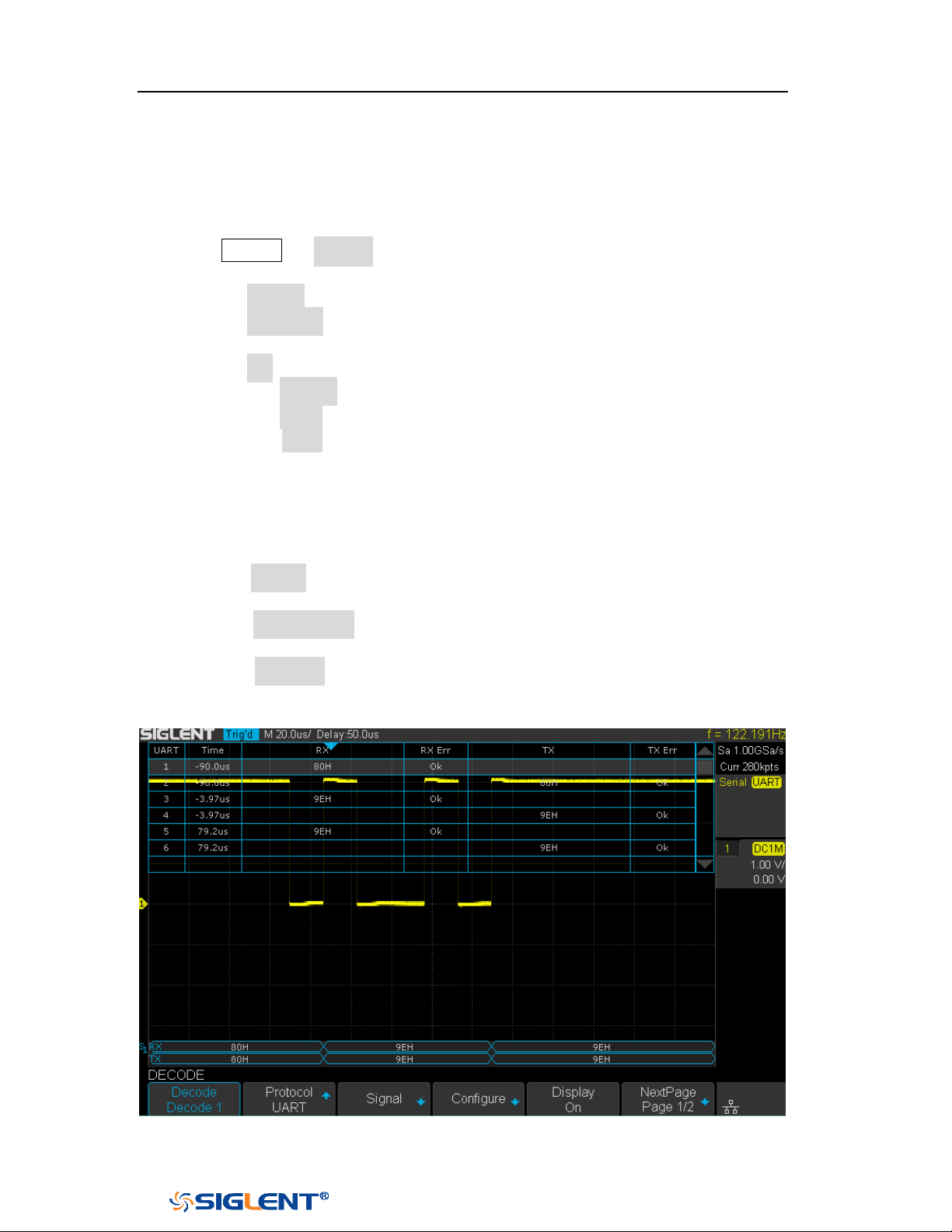
SDS1000X-E&SDS1000X-U User Manual
109
WWW.SIGLENT.COM
UART Serial Decode
After completing the setup of UART signal and trigger, we will decode UART signals.
Operation steps as follows.
1. Press Decode → Decode. Select one of the options from the Decode1 and
Decode2.
2. Press the Display and select On to display the result of decoding.
3. Press the Configure to set the baud rate, data length, parity check, stop bit, idle
level and bit order. Refer to “Setup for UART Signals” to set parameters.
4. Press the List to enter the LIST function menu.
Press the Display and choose the same options as the first step.
Press the Scroll and turn the Universal Knob to view all frames.
Press the Lines and set the number of lines by Universal Knob. The range
of the lines is 1 to 7.
Users can export the result list of the package to the external USB storage
device in csv format (only when the USB flash disk is detected). Saving the
data (*.csv) is similar to the operation of setup files, see the section
"External save and recall" for details.
5. Press the Format to change the character encoding format of the decoding’s
result.
6. Press the Copy Setting to enter the COPY function menu to synchronize the
corresponding bus configuration and trigger configuration.
7. Press the Tips Info to turn on or off the decoding limit prompt. When the
decoding frame number reaches the maximum, it will pop up "Decoding to
maximum frame number limitation!"
Figure 58 UART Decode
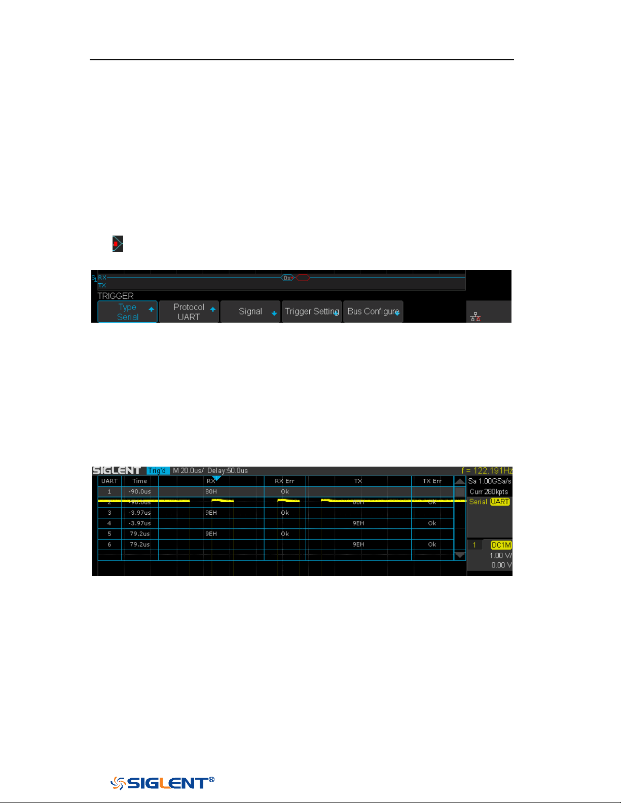
SDS1000X-E&SDS1000X-U User Manual
110
WWW.SIGLENT.COM
Interpreting UART Decode
The frames of decoding result:
RX — the decoding result of the data received.
TX — the decoding result of the data transmitted.
Indicates there is not enough space on the display to show the complete
content of a frame, and some content is hidden.
Figure 59 UART Decode Bus Display
The lists of decoding result:
Time— the horizontal displacement between current frame and trigger
position.
RX — the receiving channel.
TX — the transmitting channel.
RX Err— Parity error or unknown error in the data received.
TX Err— Parity error or unknown error in the data transmitted.
Figure 60 UART Decode List Display
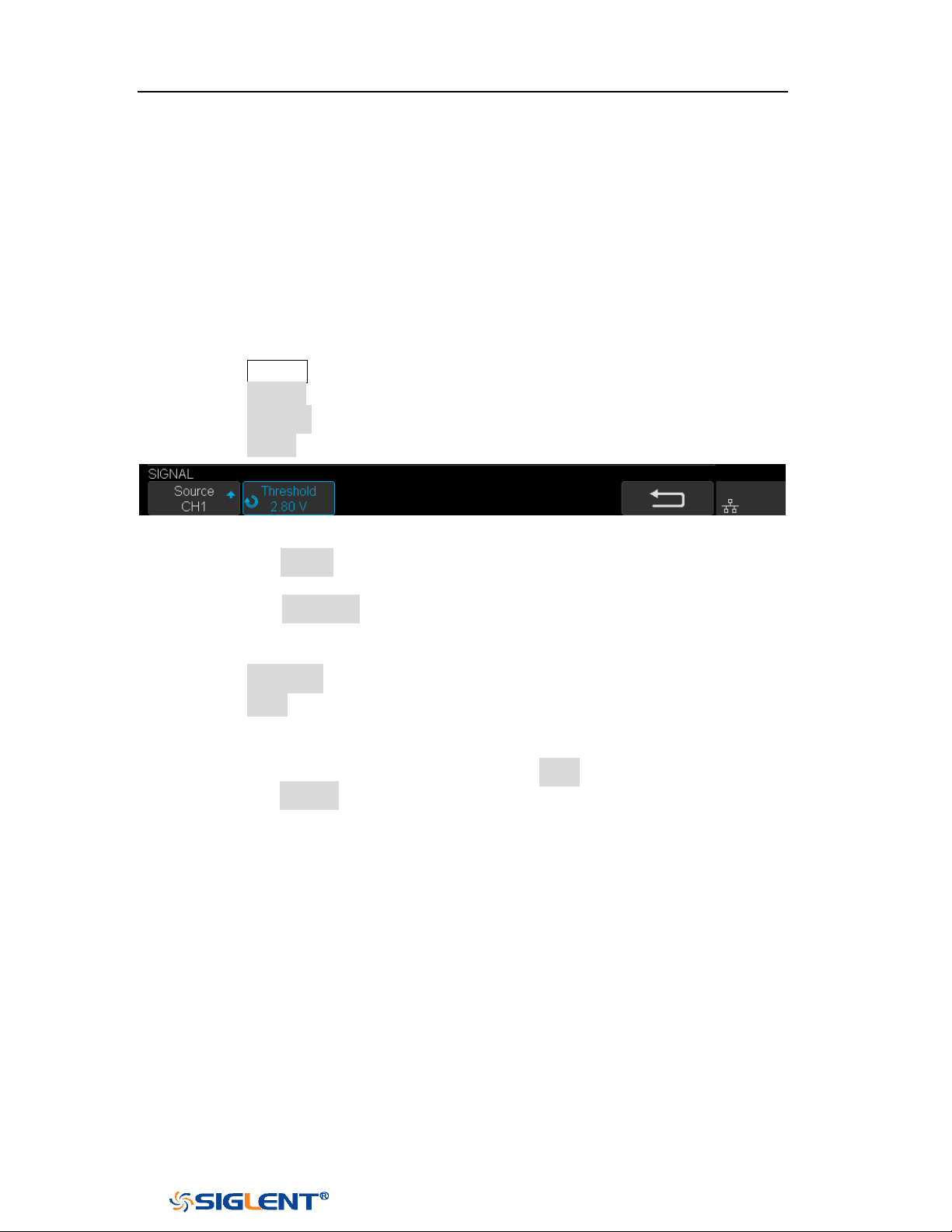
SDS1000X-E&SDS1000X-U User Manual
111
WWW.SIGLENT.COM
CAN Trigger and Serial Decode
Please in order of “
Setup for CAN Signals”, “CAN Trigger” and “CAN Serial
Decode” to trigger and decode the signals.
Setup for CAN Signals
1. Press the Decode key to enter the DECODE function menu.
2. Press the Decode softkey and select the desired slot (Decode1 or Decode2).
3. Press the Protocol softkey and then select CAN by turning Universal Knob.
4. Press the Signal softkey to enter the SIGNAL menu as below shows.
Figure 61CAN SIGNAL Menu
a. Press the Source softkey to select the channel that is connected to the CAN
signal.
b. Press the Threshold key to set the CAN signal’s threshold voltage level by
Universal Knob. The threshold voltage level is for decoding, and it will be
regard as the trigger voltage level when set the trigger type to serial.
5. Press the Configure softkey to enter the BUS CONFIG menu.
6. Press the Baud to set baud rate by Universal Knob.
The baud rate can be set as predefined value (from 5kb/s to 1Mb/s) or
custom value (from 5kb/s to 1Mb/s).
If the desired baud rate is not listed, press Baud and select custom option,
press the Custom and turn the Universal Knob to set the desired baud rate.

SDS1000X-E&SDS1000X-U User Manual
112
WWW.SIGLENT.COM
CAN Trigger
This part will provide a brief introduction and description for the operation of the
CAN trigger.
Trigger Conditions
Start— the oscilloscope will be triggered at the start bit of a frame.
Remote — the oscilloscope will be triggered by a remote frame with specified
ID.
ID — the oscilloscope will be triggered by a remote or data frame that have
specified ID.
ID+DATA— the oscilloscope will be triggered by data frame that have specified
ID and data.
Error — the oscilloscope will be triggered by an error frame.
Operation Steps
1. Press the Setup to enter the TRIGGER function menu.
2. Press the Type and select Serial.
3. Press the Protocol and select CAN.
4. Press the Trigger Setting to enter the CAN TRIG SET menu.
5. Press the Condition and select the trigger condition by Universal Knob:
If you select the REMOTE and ID condition:
a. Press the ID Bits to set the length of ID (11bits or 29 bits).
b. Press the Curr ID Byte and use the Universal Knob to select the byte
that you want to set.
c. Press the ID and set the ID’s value by the Universal Knob.
(Tips: In order to make it convenient for the operation to set the
parameters, ID b is split into several bytes. For example, if the ID’s length is
11 bits, it will be split into two bytes, a byte includes 8 bits. If “1st byte” is
selected, only the 8 least significant bits can be changed.)
If you select the
ID+DATA condition:
a. Press the ID bits softkey to select the ID’s length (11 or 29 bits).
b. Press the Curr ID Byte softkey and use Universal Knob to select the byte
that you want to modify.
c. Press the ID softkey and set the ID’s value by Universal Knob.
d. Press the Data softkey and set the value of the first byte by Universal
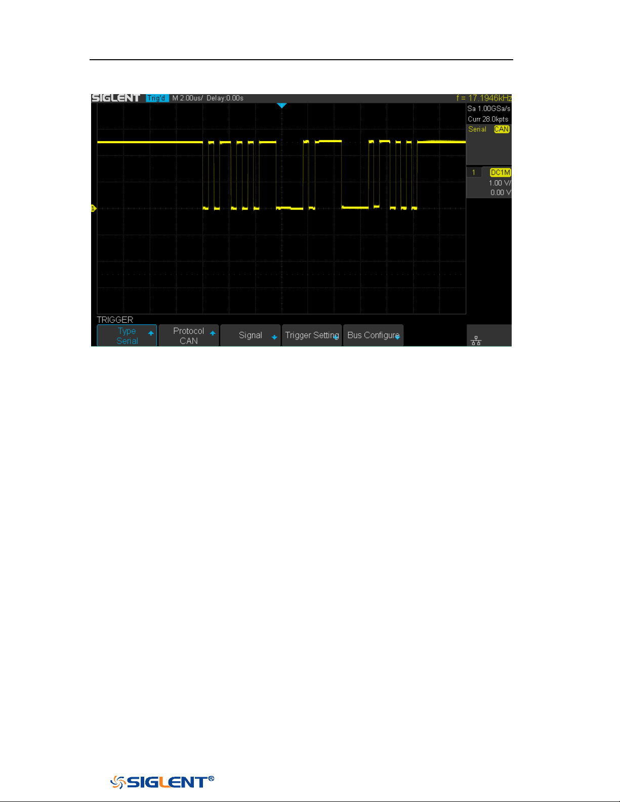
SDS1000X-E&SDS1000X-U User Manual
113
WWW.SIGLENT.COM
Knob.
Figure 62 CAN Trigger
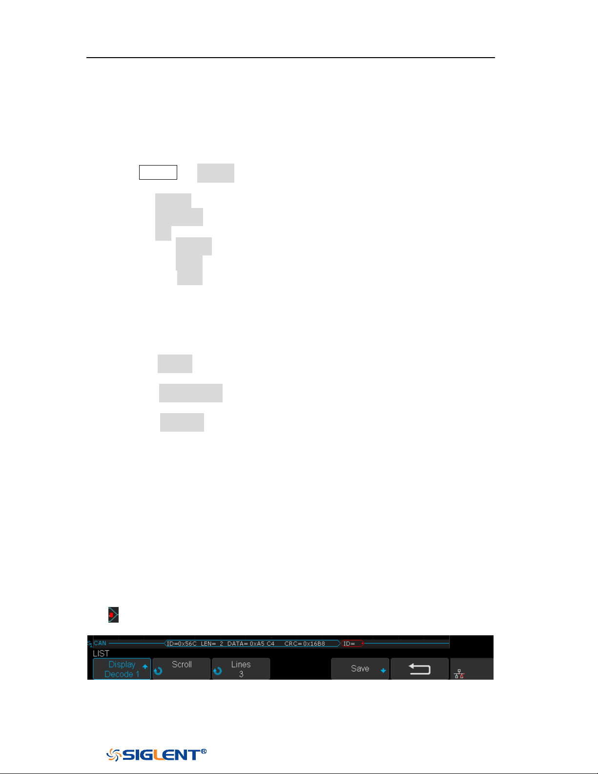
SDS1000X-E&SDS1000X-U User Manual
114
WWW.SIGLENT.COM
CAN Serial Decode
After completing the setup of can signal and trigger, we will decode CAN signals.
Operation steps as follows.
1. Press Decode → Decode. Select one of the options from the Decode1 and
Decode2.
2. Press the Display and select On to display the result of decoding.
3. Press the Configure to set the baud rate.
4. Press the List to enter the LIST function menu.
Press the Display and choose the same options as the first step.
Press the Scroll and turn the Universal Knob to view all frames.
Press the Lines and set the number of lines by Universal Knob. The range
of the lines is 1 to 7.
Users can export the result list of the package to the external USB storage
device in csv format (only when the USB flash disk is detected). Saving the
data (*.csv) is similar to the operation of setup files, see the section
"External save and recall" for details.
5. Press the Format to change the character encoding format of the decoding’s
result.
6. Press the Copy Setting to enter the COPY function menu to synchronize the
corresponding bus configuration and trigger configuration.
7. Press the Tips Info to turn on or off the decoding limit prompt. When the
decoding frame number reaches the maximum, it will pop up "Decoding to
maximum frame number limitation!"
Interpreting CAN Decode.
The frame of decoding result:
Arbitration field is displayed in frame
Control field is displayed in frame
Data field is displayed in frame
CRC field is displayed in frame
Indicates there is not enough space on the display to show complete
content of a frame and some content is hidden.
Figure 63 CAN Decode Bus Display
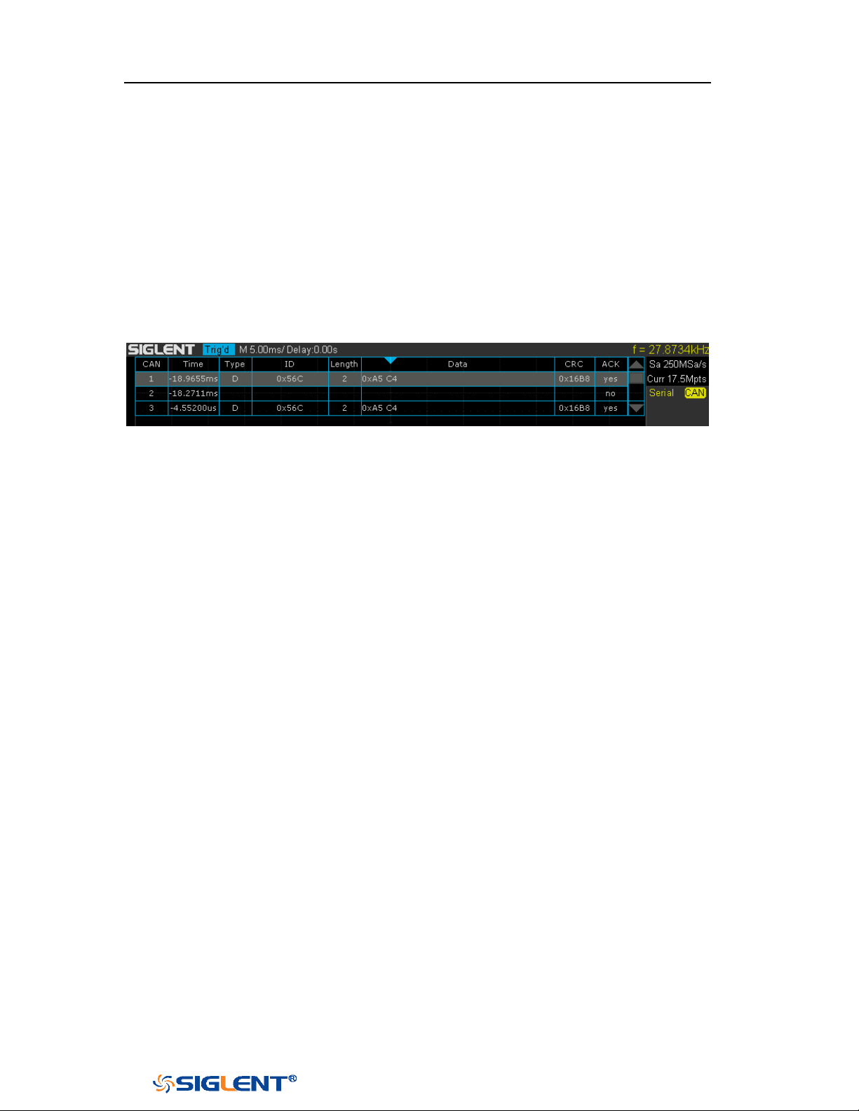
SDS1000X-E&SDS1000X-U User Manual
115
WWW.SIGLENT.COM
The list of decoding result:
Time— the horizontal displacement between current frame and trigger
position.
Type — the type of frames, “D” represents data frame, “R” represents
remote frame.
ID — the id of frames, the oscilloscope can automatically detect the length
of frame’s id (11 bits or 27 bits).
Length — the length of data field.
Data — the value of data field.
CRC — the value of CRC (Cyclic Redundancy Check) field.
ACK — Acknowledgment bit.
Figure 64 CAN Decode List Display
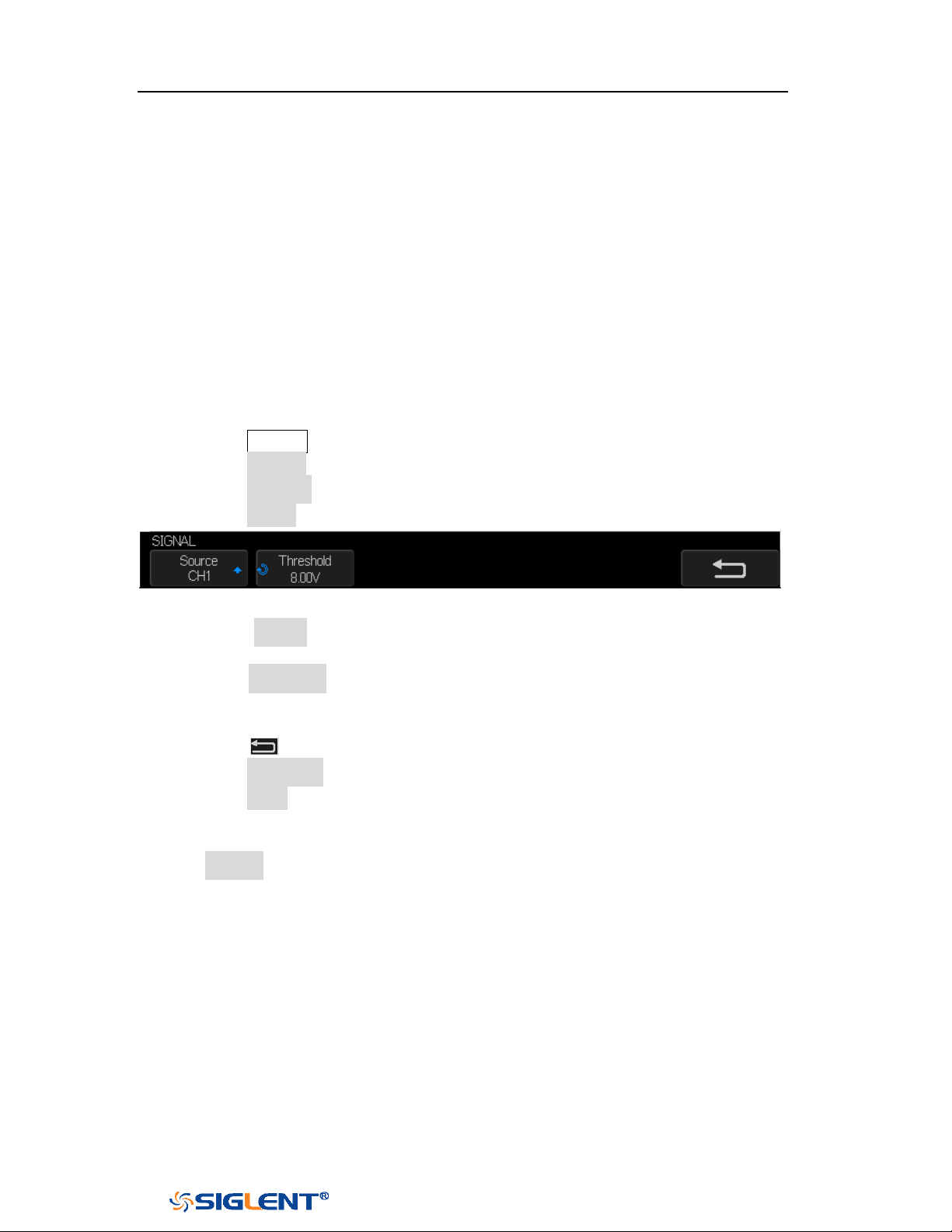
SDS1000X-E&SDS1000X-U User Manual
116
WWW.SIGLENT.COM
LIN Trigger and Serial Decode
Please take the order of “
Setup for LIN Signals”, “LIN Trigger” and “LIN Serial
Decode” to trigger and decode the signals.
Setup for LIN Signals
There are two steps of setting the LIN signal, connecting the signal to oscilloscope,
specifying the parameters of each input signal.
1. Press the
Decode button to enter the DECODE function menu.
2. Press the Decode softkey and select the desired slot (Decode1 or Decode2).
3. Press the Protocol softkey and then select LIN by turning Universal Knob.
4. Press the Signal softkey to enter the SIGNAL menu as below shows.
Figure 65 LIN SIGNAL Menu
5. Press the Source softkey to select the channel that is connected to the LIN
signal.
6. Press the Threshold softkey and set the LIN signal’s threshold voltage level by
Universal Knob. The threshold voltage level is for decoding, and it will be
regard as the trigger voltage level when set the trigger type to serial.
7. Press the softkey to return previous menu.
8. Press the Configure softkey to enter the BUS CONFIG menu.
9. Press the Baud softkey to set baud rate.
The baud rate can be set as predefined value.
If the desired baud rate is not listed, select custom option, press the
Custom and turn the Universal Knob to set the desired baud rate.

SDS1000X-E&SDS1000X-U User Manual
117
WWW.SIGLENT.COM
LIN Trigger
This part will provide a brief introduction and description for the operation of the
LIN trigger.
Trigger Conditions
Break — the oscilloscope will be triggered at the position of break field’s break
delimiter.
ID (Frame ID) — the oscilloscope will be triggered at the position of identifier
field’s stop bit, if the value of a frame’s ID is equal to specified value.
(Note: If the data’s value is 0xXX, any data value will be matched)
ID + Data (Frame ID and Data) — the oscilloscope triggers when a frame with
an ID and data equal to the selected values is detected. Use the Universal Knob
to select the value for the ID, Data1 and Data2.
a. The ID’s value is the same as set value.
b. If you have set either Data1’s or Data2’s value, and the signal has a data is
the same as that value. If you have set both Data1’s and Data2’s value, the
signal should has two consecutive data, the first data’s value is Data1,
second data value is Data2.
(Note: If the data’s value is 0xXX, any data value will be matched)
Data Error —the oscilloscope will be triggered when errors (such as ID check
error, checksum error, sync byte field error) are detected.
Operation Steps
1. Press the Setup button to enter the TRIGGER function menu.
2. Press the Type and select Serial.
3. Press the Protocol and select I2C.
4. Press the Trigger Setting softkey to enter LIN TRIG SET menu.
5. Press the Condition and select the trigger condition by Universal Knob:
If you select
ID condition:
a. Press the ID softkey and set its value by turning the Universal Knob.
If you select ID+DATA condition:
a. Press the ID softkey and set its value by turning the Universal Knob.
b. Press the DATA1 softkey and set its value by turning the Universal
Knob.
c. Press the DATA2 softkey and set its value by turning the Universal
Knob.
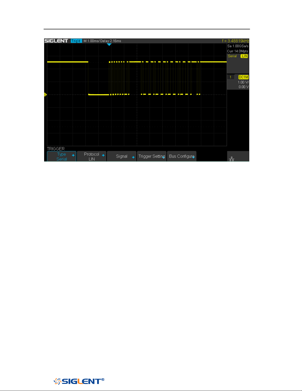
SDS1000X-E&SDS1000X-U User Manual
118
WWW.SIGLENT.COM
Figure 66 LIN Trigger
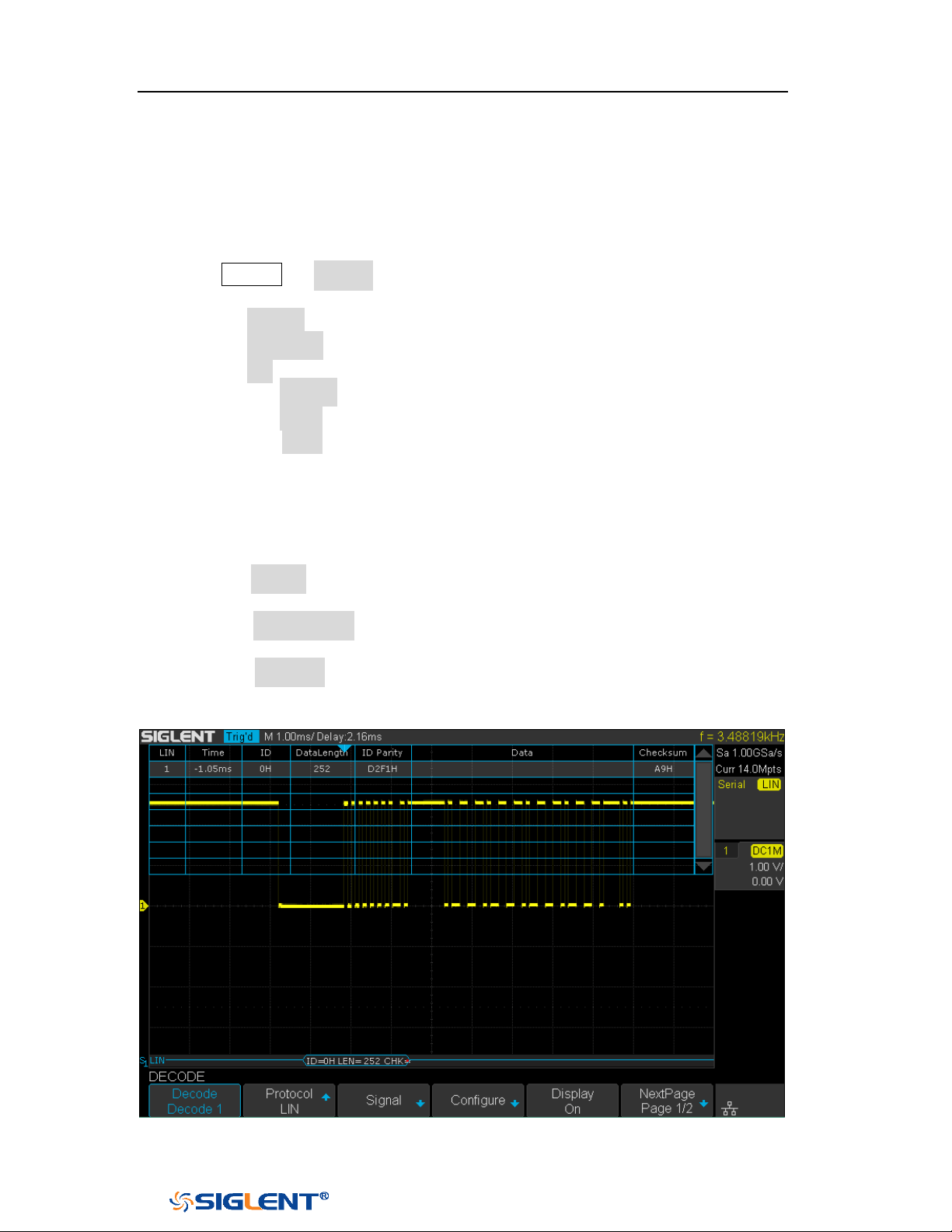
SDS1000X-E&SDS1000X-U User Manual
119
WWW.SIGLENT.COM
LIN Serial Decode
After completing the setup of LIN signal and trigger, we will decode LIN signals.
Operation steps as follows.
1. Press Decode → Decode. Select one of the options from the Decode1 and
Decode2.
2. Press the Display and select On to display the result of decoding.
3. Press the Configure to set the baud rate.
4. Press the List to enter the LIST function menu.
Press the Display and choose the same options as the first step.
Press the Scroll and turn the Universal Knob to view all frames.
Press the Lines and set the number of lines by Universal Knob. The range
of the lines is 1 to 7.
Users can export the result list of the package to the external USB storage
device in csv format (only when the USB flash disk is detected). Saving the
data (*.csv) is similar to the operation of setup files, see the section
"External save and recall" for details.
5. Press the Format to change the character encoding format of the decoding’s
result.
6. Press the Copy Setting to enter the COPY function menu to synchronize the
corresponding bus configuration and trigger configuration.
7. Press the Tips Info to turn on or off the decoding limit prompt. When the
decoding frame number reaches the maximum, it will pop up "Decoding to
maximum frame number limitation!"
Figure 67 LIN Decode
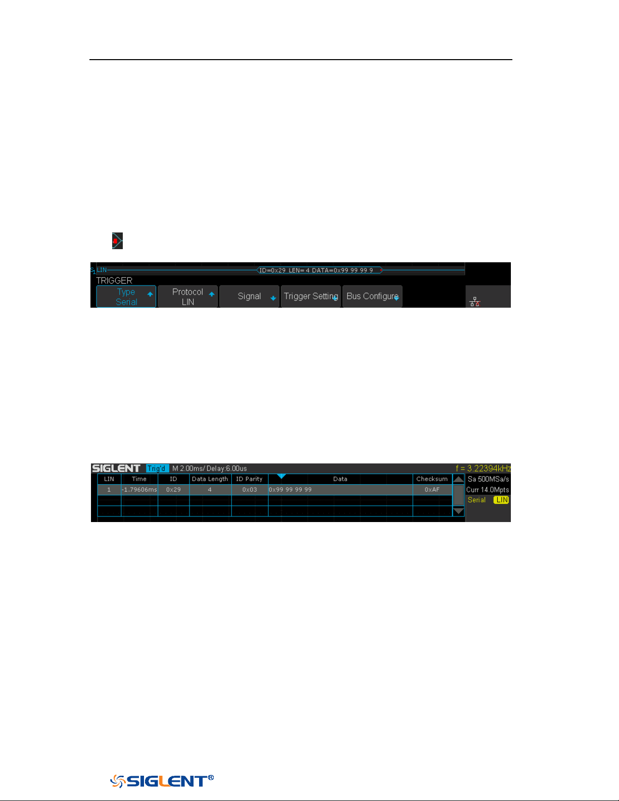
SDS1000X-E&SDS1000X-U User Manual
120
WWW.SIGLENT.COM
Interpreting LIN Decode
The frame of decoding result:
Protected Identifier Field is displayed in frame
Data Length is displayed in frame
Data Field is displayed in frame.
Checksum Field is displayed in frame.
Indicates there is not enough space on the display to show complete
content of a frame and some content is hidden.
Figure 68 LIN Decode Bus Display
The list of decoding result:
Time— the horizontal displacement between current frame and trigger
position.
ID — the value of frame’s Protected Identifier Field.
Data Length — the length of Data Field.
ID Parity — the two check bits of Protected Identifier Field.
Data — the value of Data Field.
Checksum— the value of Checksum Field.
Figure 69 LIN Decode List Display

SDS1000X-E&SDS1000X-U User Manual
121
WWW.SIGLENT.COM
Reference Waveform
The oscilloscope can save analog channel or math waveforms to the reference
waveform locations in the oscilloscope. Then, a reference waveform can be
displayed and compared against other waveforms. All reference waveforms can be
displayed at a time.
The contents of this chapter:
Save REF Waveform to Internal Memory
Display REF Waveform
Adjust REF Waveform
Clear REF Waveform
SDS1000X-E&SDS1000X-U User Manual
122
WWW.SIGLENT.COM
Note: The REF waveforms are non-volatile. The REF waveform can still be
saved after restarts or default operation.
Save REF Waveform to Internal Memory
Do the following steps to save the REF waveform to internal memory:
1. Press the
REF button on the front panel to enter the REF WAVE function menu.
Note that when the time horizontal format is in X-Y mode, REF function cannot
be enabled.
2. Press the Source softkey; then, turn the Universal Knob to select the source of
reference channel. The source includes analog channel and math waveforms.
3. Press the Location softkey; then, turn the Universal Knob to select the position
to save the REF waveform. The source includes analog channel and math
waveforms.
4. Press the Save softkey to save the channel or math waveform to the appointed
location. The vertical scale information and the vertical offset of the waveform
will be saved at the same time. It will pop out the message “Saved to internal
file REF*” when the waveform has been saved successfully.
Display REF Waveform
To the following steps to display REF waveform:
1. Press the
REF button on the front panel to enter the REF WAVE function menu.
2. Press the Location softkey; then, turn the Universal Knob to select the REF
waveform that you want to display.
3. Press the Display softkey to select On to display the REF waveform on the
screen. Only saved location can be displayed. The oscilloscope can display all
four reference waveforms at the same time.
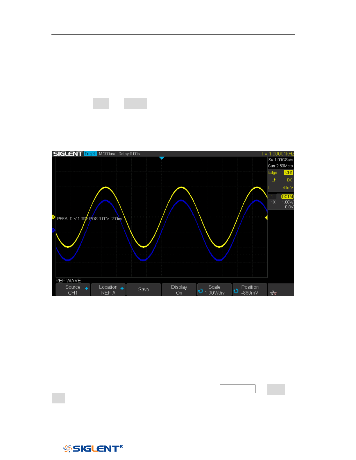
SDS1000X-E&SDS1000X-U User Manual
123
WWW.SIGLENT.COM
Adjust REF Waveform
1. Please refer to the “
Display REF Waveform” above to display the desired
reference waveform.
2. Press the Scale and Position softkey and turn the Universal Knob to adjust the
vertical scale and position of the reference waveform. The vertical scale and
position information display at the middle of the screen.
The initial values display at the middle of the screen is the setup that when the
reference waveform been saved.
Figure 70 Reference Waveform
Clear REF Waveform
The oscilloscope does not have the “Clear” option under the REF WAVE function
menu. To clear the appointed reference waveform, you can save a new reference
waveform to the same location to cover it. Or follow the Save/Recall → Recall →
type and select Security Erase to clear the stored waveform.

SDS1000X-E&SDS1000X-U User Manual
124
WWW.SIGLENT.COM
Note: if the analog channel or the math function is cut off (waveforms do not
display on the screen completely), the resulting math will also be cut off.
Math
The oscilloscope supports many math operations between analog channels
including addition (+), subtraction (-), multiplication (*), division (/), FFT,
differential (d/dt), integral (∫dt), square root (√). The resulting math waveform is
displayed in white and labeled with “M”. You can use cursors to measure it.
The contents of this chapter:
Units for Math Waveforms
Math Operators

SDS1000X-E&SDS1000X-U User Manual
125
WWW.SIGLENT.COM
Units for Math Waveforms
Use the channel function menu to set the unit of each channel to “
V” or “A”.
The oscilloscope math operation includes units as below:
Math Operation
Unit
Addition (+)or subtraction (-)
V, A
multiplication (*)
V
∧
2, A
∧
2 or W
division (/)
SDS1000X-E:None, Ω (Resistance unit Ohms) or
S (conductance unit Siemens)
SDS1000X-U:None, V*A^-1 or V^-1*A
FFT
dBVrms, Vrms, dBm, dBArms, Arms
differential (d/dt)
SDS1000X-E:V/S or A/S (V/second or A/second)
SDS1000X-U:V*S^-1 or A*S^-1
integral (∫dt)
Wb, C
square root ( )
V
∧
1/2 or A
∧
1/2
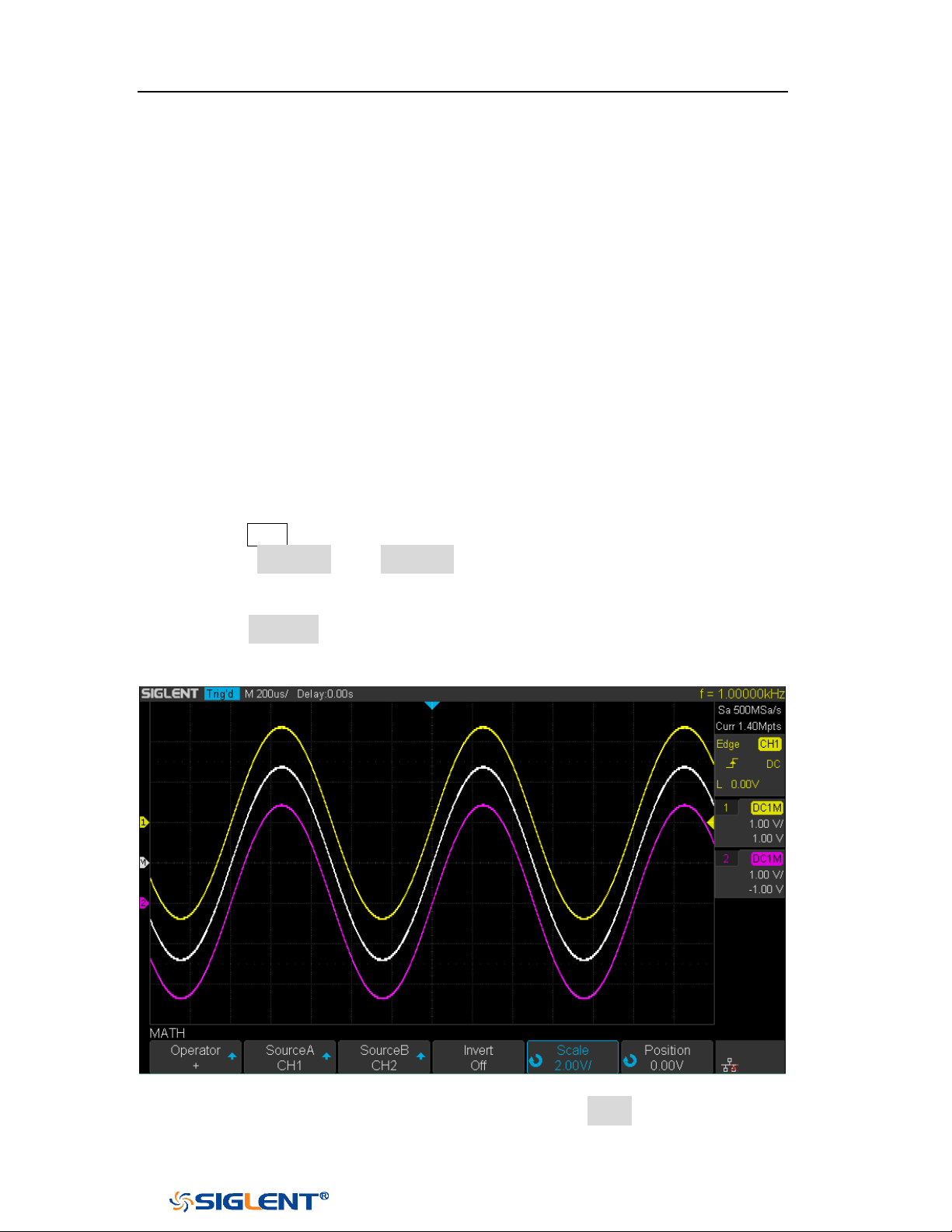
SDS1000X-E&SDS1000X-U User Manual
126
WWW.SIGLENT.COM
Math Operators
The oscilloscope supports math count operation (Addition, subtraction,
multiplication, division), FFT (Fourier transform) operation and math function
operation (differential, integral, square root).
Addition or Subtraction
Math operators perform arithmetic operations add or subtract operation on any
two analog input channels. When you select addition or subtraction, the
Source A
and Source B values are added or subtracted point by point, and the result is
displayed.
1. Press the Math button on the front panel to enter the MATH function menu.
2. Press the Source A and Source B softkey respectively, and then turn the
Universal Knob to select the source to do math operation. Addition or
Subtraction can be applied between analog channels.
3. Press the Operator softkey and then turn the Universal Knob to select + or - to
make addition or subtraction operation. The resulting math waveform is
displayed in white and labeled with “M”.
Figure 71 C1+C2 Waveform
4. If you want to invert the math waveform, press the Invert button and set the
option to On to invert the display of the math waveform.
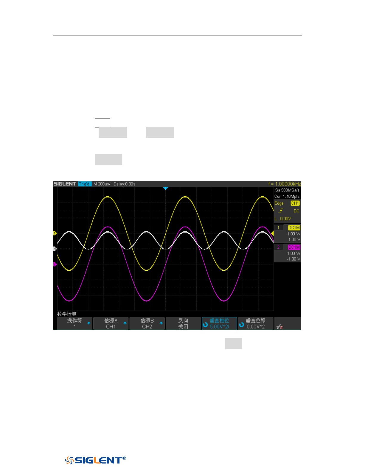
SDS1000X-E&SDS1000X-U User Manual
127
WWW.SIGLENT.COM
Multiplication and Division
Math operators perform arithmetic operations multiplication or division operation
on any two analog input channels. When you select multiplication or division, the
Source A and Source B values are multiplied or divided point by point and the result
is displayed.
1. Press the Math button on the front panel to enter the MATH function menu.
2. Press the Source A and Source B softkey respectively, and then turn the
Universal Knob to select the source to do math operation. Multiplication or
Division can be applied between analog channels.
3. Press the Operator softkey and then turn the universal to select * or / to make
multiplication or division operation. The resulting math waveform is displayed
in white and labeled with “M”.
Figure 72 C1*C2 Waveform
4. If you want to invert the math waveform, press the Invert button and set the
option to On to invert the display of the math waveform.
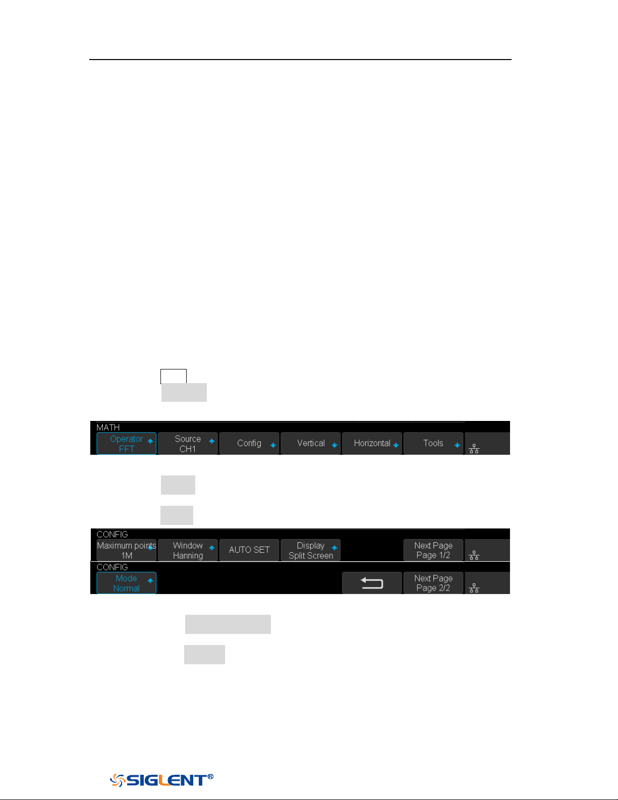
SDS1000X-E&SDS1000X-U User Manual
128
WWW.SIGLENT.COM
FFT Operation
FFT is used to compute the fast Fourier transform using analog input channels. FFT
takes the digitized time record of the specified source and transforms it to the
frequency domain. When the FFT function is selected, the FFT spectrum is plotted
on the oscilloscope display as magnitude in dBV versus frequency. The readout for
the horizontal axis changes from time to frequency (Hertz) and the vertical readout
changes from V to dB.
FFT operation can facilitate the following works:
Measure harmonic components and distortion in the device under test
Measure the characteristics of the noise in DC power
Analyze vibration
To display a FFT waveform:
1. Press the Math button on the front panel to open the MATH function menu.
2. Press the Operator softkey and then turn the Universal Knob to select FFT. The
resulting math waveform is displayed in white and labeled with “M”.
Figure 73 FFT Menu
3. Press the Source softkey, and then turn the Universal Knob to select the source
to do FFT operation. Analog channels can be used as the source.
4. Press the Config softkey to enter CONFIG menu.
Figure 74 FFT CONFIG Menu
Press the Maximum points softkey, and then turn the Universal Knob to
select the Maximum points.
Press the Window softkey, and then turn the Universal Knob to select an
appropriate window.
Spectral leakage can be considerably decreased when a window function
is used. The oscilloscope provides five windows (Rectangle, Blackman,
Hanning, Hamming and Flattop) which have different characteristics and
are applicable to measure different waveforms. You need to select the
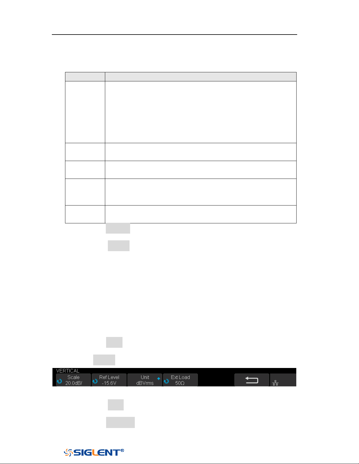
SDS1000X-E&SDS1000X-U User Manual
129
WWW.SIGLENT.COM
window function according to different waveforms and their
characteristics. Please read the table below carefully to make an
appropriate option according to the input signal.
Window
Applications and Characteristics
Rectangle
These are normally used when the signal is transient
(completely contained in the time-domain window) or known
to have a fundamental frequency component that is an integer
multiple of the fundamental frequency of the window. Signals
other than these types will show varying amounts of spectral
leakage and scallop loss, which can be corrected by selecting
another type of window.
Hanning
These reduce leakage and improve amplitude accuracy.
However, frequency resolution is also reduced.
Hamming
These reduce leakage and improve amplitude accuracy.
However, frequency resolution is also reduced.
Flat Top
This window provides excellent amplitude accuracy with
moderate reduction of leakage, but with reduced frequency
resolution.
Blackman
It reduces the leakage to a minimum, but with reduced
frequency resolution.
Press the Auto set softkey to automatically set the appropriate parameters
for the FFT measurement.
Press the Display softkey to select Split Screen, Full Screen or Exclusive
display mode.
Split Screen: Time domain waveform and frequency domain waveform are
displayed separately. The time domain waveform is on the upper half
screen, while the frequency domain waveform is located within the lower
half of the display. In Split mode, if Zoom is enabled, the zoom waveform
and the frequency domain waveform are displayed on the lower half
screen together.
Full Screen: Time-domain waveform and frequency-domain waveform are
displayed together.
Exclusive: Only the frequency-domain waveform is displayed.
Press the Mode softkey to select Normal, Max-Hold or Average. When you
select Average, it is necessary to set the average times.
5. Press the Vertical softkey to enter VERTICAL menu.
Figure 75 VERTICAL Menu
Press the Scale softkey, and then turn the Universal Knob to select the
desired vertical FFT scale
Press the Ref Level softkey, and then turn the Universal Knob to select the
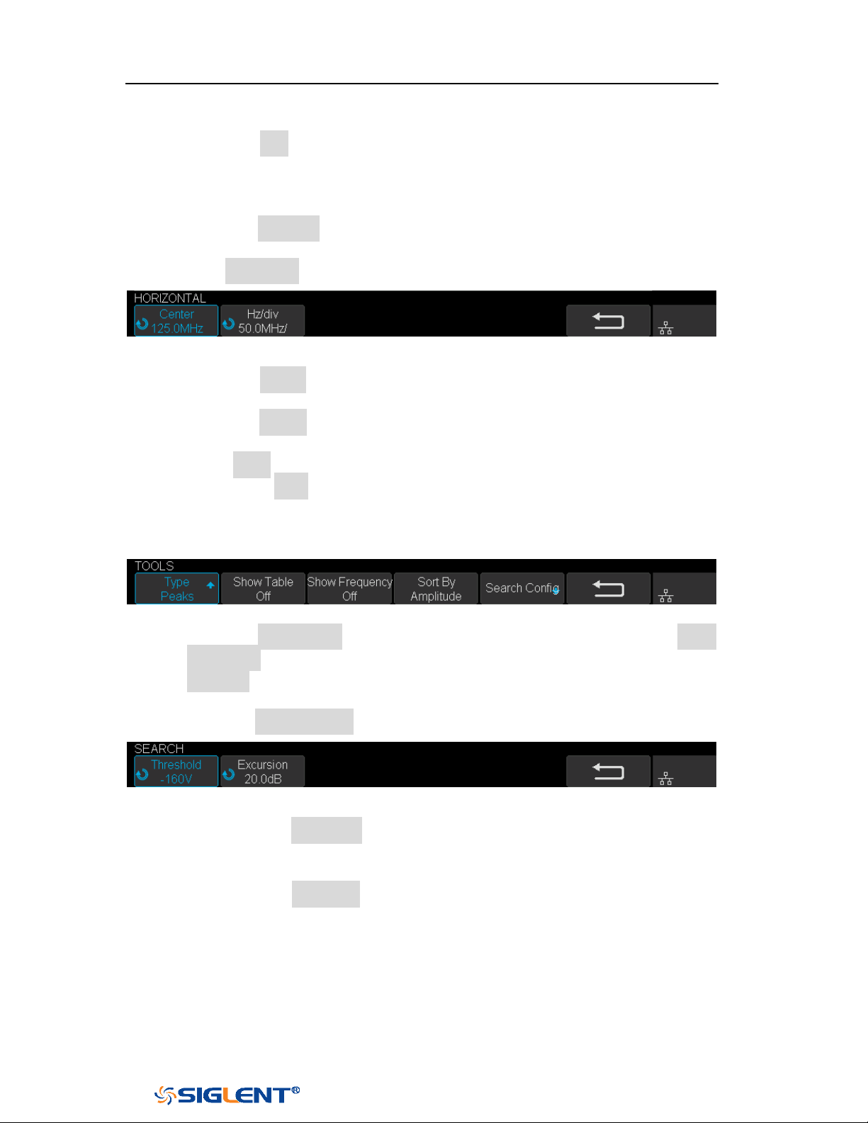
SDS1000X-E&SDS1000X-U User Manual
130
WWW.SIGLENT.COM
desired vertical FFT offset.
Press the Unit softkey to select the unit of vertical axis. The units of the
vertical axis can be dBVrms, dBm, Vrms or dBArms, Arms, which use a
logarithmic scale or a linear scale to display vertical amplitude
respectively.
Press the Ext Lode softkey and then turn the Universal Knob to select the
external load value.
6. Press the Horizontal softkey to enter HORIZONTAL menu.
Figure 76 HORIZONTAL Menu
Press the Center softkey, and then turn the Universal Knob to select the
desired center frequency.
Press the Hz/div softkey, and then turn the Universal Knob to select the
desired resolution frequency.
7. Press the Tools softkey to enter TOOLS menu(only 4-channel supports this
function). Press Type softkey to select the type of tools. The type of the tools
can be Peaks, Markers, or Off.
Peaks: Automatically mark the peak of the current FFT waveform according to
the search configuration.
Figure 77 FFT Peaks Menu
Press the Show Table softkey to display a table of peak, and press Show
Frequency softkey to display the frequency value of the peak. Press the
Sort By softkey continuously to set the table sorting by Amplitude or
Frequency.
Press the Search Config softkey to set search configuration.
Figure 78 SEARCH Menu
a. Press the Threshold softkey and turn the Universal knob to set the
minimum peak amplitude. Only peaks larger than the peak limit can
be judged as peaks.
b. Press the Excursion softkey and turn the Universal knob to set the
difference between the peak value and the minimum Amplitude on
both sides. Only when the difference is greater than the peak value of
peak offset can the peak value be determined.
Markers: Customize the marker locations on the FFT waveform based on search
configuration.
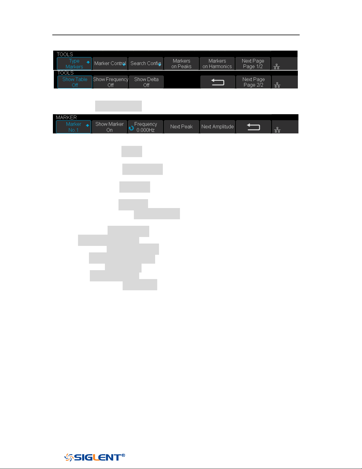
SDS1000X-E&SDS1000X-U User Manual
131
WWW.SIGLENT.COM
Figure 79 FFT Markers Menu
Press Markers Control softkey to enter MARKER Menu.
Figure 80 Marker Control Menu
a. Press the Marker softkey continuously to select the marker number
from NO.1~NO.8.
b. Press the Show Marker softkey continuously to turn on or off the
selected mark.
c. Press the Frequency softkey to set the frequency value of the selected
marker.
d. Press the Next Peak softkey to move the selected mark to the next peak.
And press the Next Amplitude softkey to move the selected marker to
the next peak with lower amplitude.(Up to 10 peaks are supported)
Press the Search Config softkey to enter the SEARCH menu. Similar to the
search configuration for peak markers.
Press the Markers on Peaks softkey to set the markers on peaks, and press
the Markers on Harmonics softkey to set the markers on harmonics.
Press the Show Table softkey to show the amplitude of the markers; press
the Show Frequency softkey to show the frequency value of the markers,
and press the Show Delta softkey to show the delta amplitude between
markers.
The following figure shows the FFT waveform displayed on the split screen and the
peak tool is turned on:
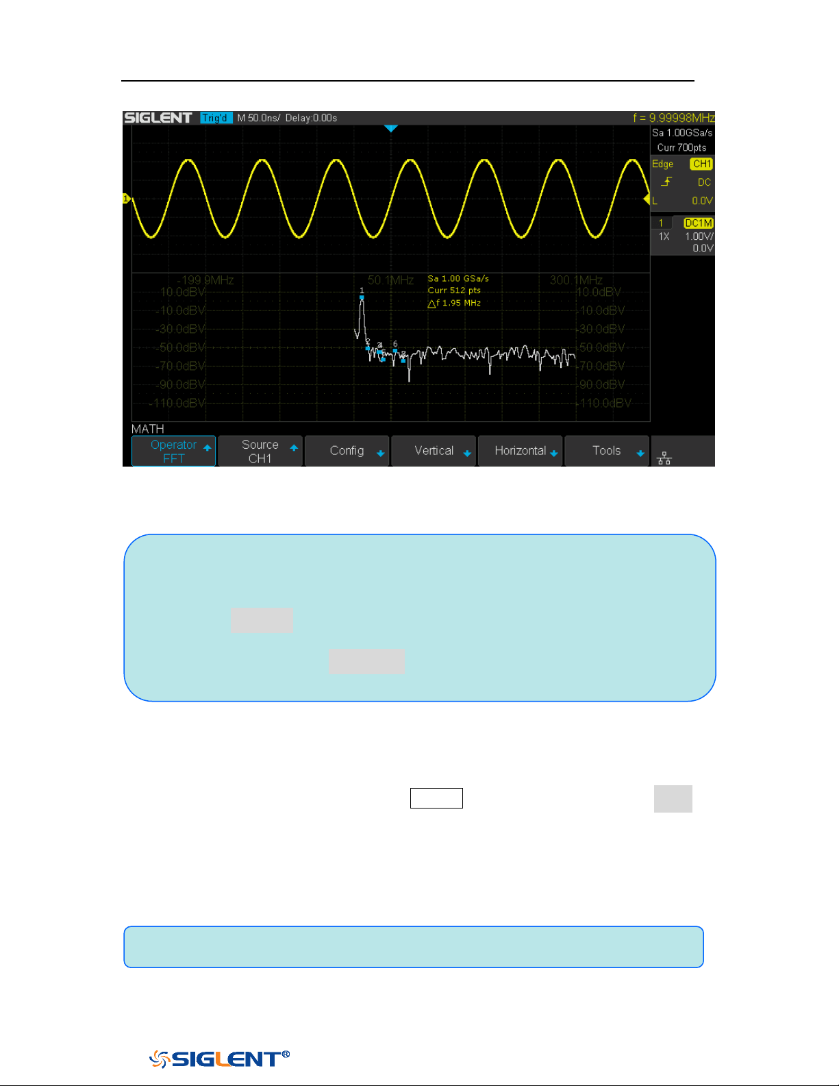
SDS1000X-E&SDS1000X-U User Manual
132
WWW.SIGLENT.COM
Figure 81 FFT Waveform
To measure FFT waveform:
To make cursor measurements, press the Cursors button, and then press the Mode
softkey to select On to turn the cursors, Use the X1 and X2 cursors to measure
frequency values and the difference between two frequency values (ΔX). Use the
Y1 and Y2 cursors to measure amplitude in dB and difference in amplitude (ΔY).
You can find the frequency value at the first occurrence of the waveform maximum
by using the X at Max Y measurement.
Note:
Signals with DC components or deviation would cause error or deviation of
the FFT waveform components. To reduce the DC components, set the
Channel Coupling to AC.
To reduce the random noise and aliasing frequency components of repetitive
or single pulse, set the Acquisition of the oscilloscope to Average.
Note: please refer to the cursors chapter to obtain the method of using cursors.

SDS1000X-E&SDS1000X-U User Manual
133
WWW.SIGLENT.COM
Math Function Operation
The oscilloscope supports math function operation including differential (d/dt),
integral (∫dt) and square root ( ).
Differentiate
d/dt (differentiate) calculates the discrete time derivative of the selected source.
Where:
d = differential waveform
y = channel 1, 2, 3, or 4 data points
i = data point index
Δ t = point- to- point time difference
The
dx option under d/dt math function operation menu shows the point- to- point
time difference, and it ranges from 0.02div to 0.40div. “div” indicates the number
of the pixel points that each division has. The oscilloscope has 50 pixel points per
division. Take 0.2div as an example: 0.2*50=10. It means to calculate the ten point’s
discrete time derivative of the selected source, and the Δ t is the ten point’s point-
to- point time difference.
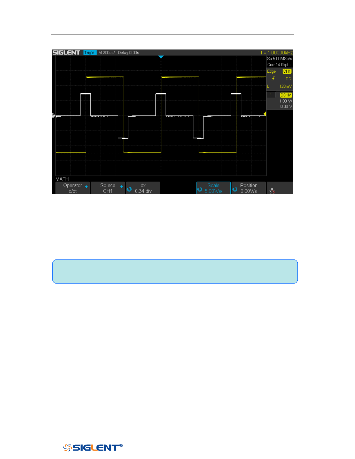
SDS1000X-E&SDS1000X-U User Manual
134
WWW.SIGLENT.COM
Figure 82 Difference Function Operation
You can use differentiate to measure the instantaneous slope of a waveform. For
example, the slew rate of an operational amplifier may be measured using the
differentiate function
Note: Because differentiation is very sensitive to noise, it is helpful to set
acquisition mode to Average.
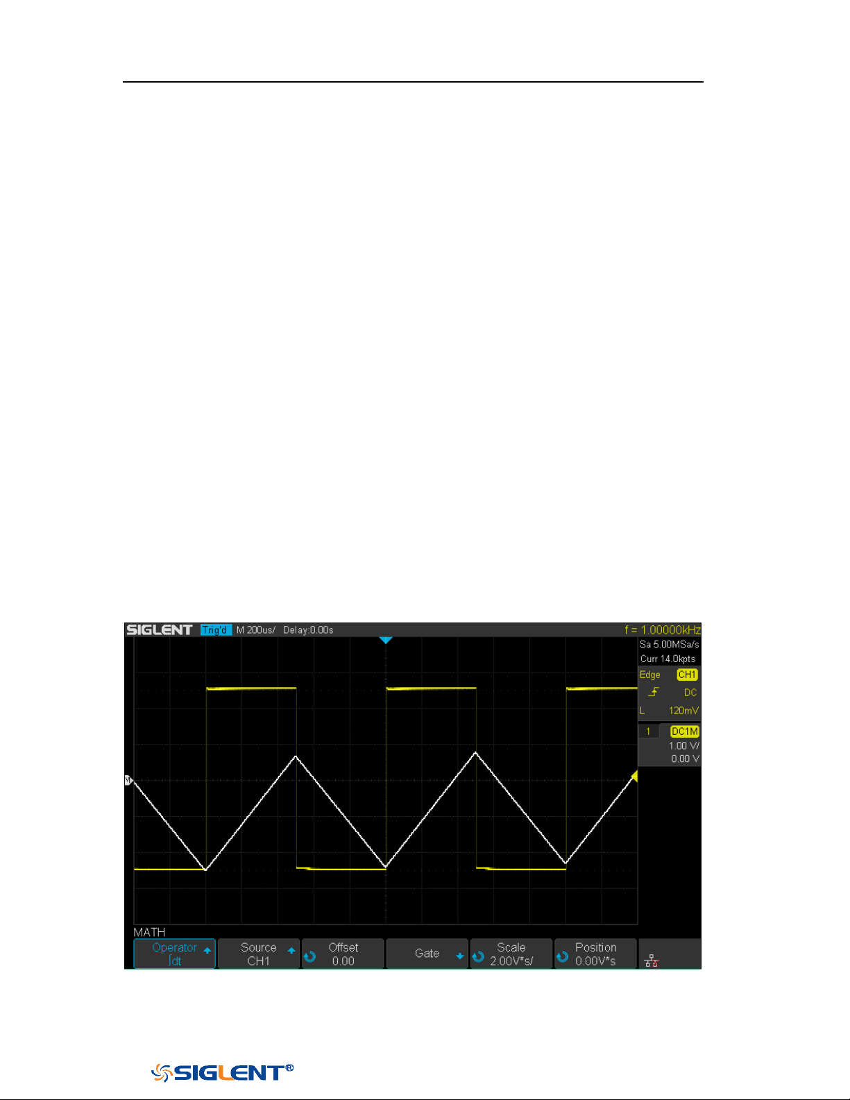
SDS1000X-E&SDS1000X-U User Manual
135
WWW.SIGLENT.COM
Integrate
dt (integrate) calculates the integral of the selected source. You can use integrate
to calculate the energy of a pulse in volt- seconds or measure the area under a
waveform.
dt plots the integral of the source using the "Trapezoidal Rule". The equation is:
n
0i
i0n
ytcI
Where:
I = integrated waveform
Δt = point- to- point time difference
y = channel 1, 2, 3, or 4 data points
c
o
= arbitrary constant
i = data point index
The integrate operator provides an
Offset softkey that lets you enter a DC offset
correction factor for the input signal. Small DC offset in the integrate function input
(or even small oscilloscope calibration errors) can cause the integrate function
output to "ramp" up or down. This DC offset correction lets you level the integrate
waveform.
Figure 83 Integral without Offset
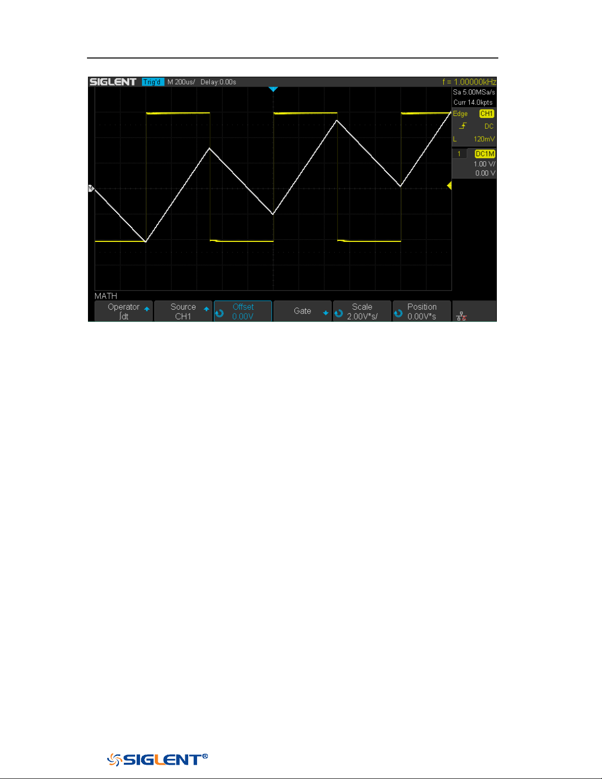
SDS1000X-E&SDS1000X-U User Manual
136
WWW.SIGLENT.COM
Figure 84 Integral with Offset
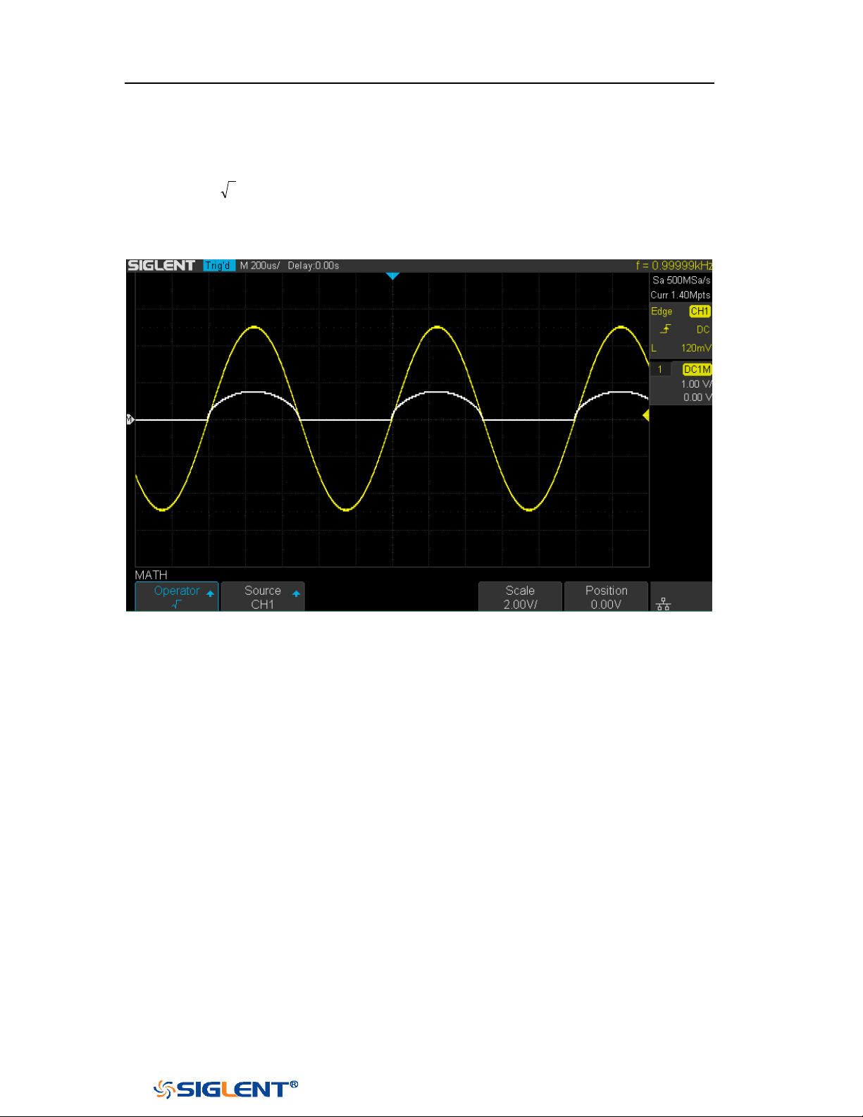
SDS1000X-E&SDS1000X-U User Manual
137
WWW.SIGLENT.COM
Square Root
Square root ( ) calculates the square root of the selected source.
Where the transform is undefined for a particular input, holes (zero values) appear
in the function output.
Figure 85 Square Root

SDS1000X-E&SDS1000X-U User Manual
138
WWW.SIGLENT.COM
Cursors
Cursors are horizontal and vertical markers that indicate X- axis values and Y- axis
values on a selected waveform source. You can use cursors to make custom
voltage, time measurements on oscilloscope signals.
X Cursors
X cursors are vertical dashed lines that adjust horizontally and can be used to
measure time (when the source is FFT waveform, X cursors measure frequency).
X1 cursor is the left (default position) vertical dotted line; it can be moved to any
place of the screen.
X2 cursor is the right (default position) vertical dotted line; it can be moved to any
place of the screen.
Use the
Universal Knob to set the X1 and X2 cursor values and the values are
displayed in the cursors box in the upper-left corner of the screen along with the
difference between X1 and X2 (△T) and 1/△T.
When set cursor type to X2-X1, use
Universal Knob will move the X1 and X2 cursors
together. The value under the menu option is the difference between the X1 and X2
cursors.
Y Cursors
Y cursors are horizontal dotted lines that adjust vertically and can be used to
measure voltage (V) or current (A). When the cursors source is the math function,
the unit will match the math function.
Y1 cursor is the top (default position) horizontal dotted line; it can be moved to any
vertical place of the screen.
Y2 cursor is the down (default position) horizontal dotted line; it can be moved to
any vertical place of the screen.

SDS1000X-E&SDS1000X-U User Manual
139
WWW.SIGLENT.COM
Use the Universal Knob to set the Y1 and Y2 cursor values and the values are
displayed in the cursors box in the top left corner of the screen along with the
difference between Y1 and Y2 (△Y).
When set cursor type to Y2-Y1, use Universal Knob will move the Y1 and Y2 cursors
together. The value under the menu option is the difference between the Y1 and Y2
cursors.

SDS1000X-E&SDS1000X-U User Manual
140
WWW.SIGLENT.COM
Make Cursor Measurements
1. Press the
Cursors button on the front panel to enter the CURSOR function
menu.
2. Press the Mode softkey and set the cursors mode to Manual or Track.
3. Press the Source softkey, and then use the Universal Knob to select the desired
source. Only analog channels, math waveforms and reference waveforms that
are displayed are available for cursors.
4. Press the X Ref and Y Ref softkey to set the reference of X cursors and Y cursors.
Position: when the horizontal/vertical scale is changed, the X/Y cursors
remain fixed to the grid position on the display.
Delay/Offset: when the horizontal/vertical is changed, the value of X/Y
cursors remain fixed.
5. To make cursor measurements:
To measure the horizontal time, use the Universal Knob to move the X1
and X2 cursors to desired place. If necessary, set the cursor type to X2-X1,
move X1 and X2 cursors together.
To measure vertical voltage or current, use the Universal Knob to move the
Y1 and Y2 cursors to desired place. If necessary, set the cursor type to
“Y2-Y1”, move Y1 and Y2 cursors together.
To adjust the transparence of the cursors message box, press the
Display/Persist button and go to the second page, press the Transparence
(20% to 80%) softkey and then turn the Universal Knob to adjust the
transparence to the desired value.
Cursor examples:
Use cursors to measure pulse width:
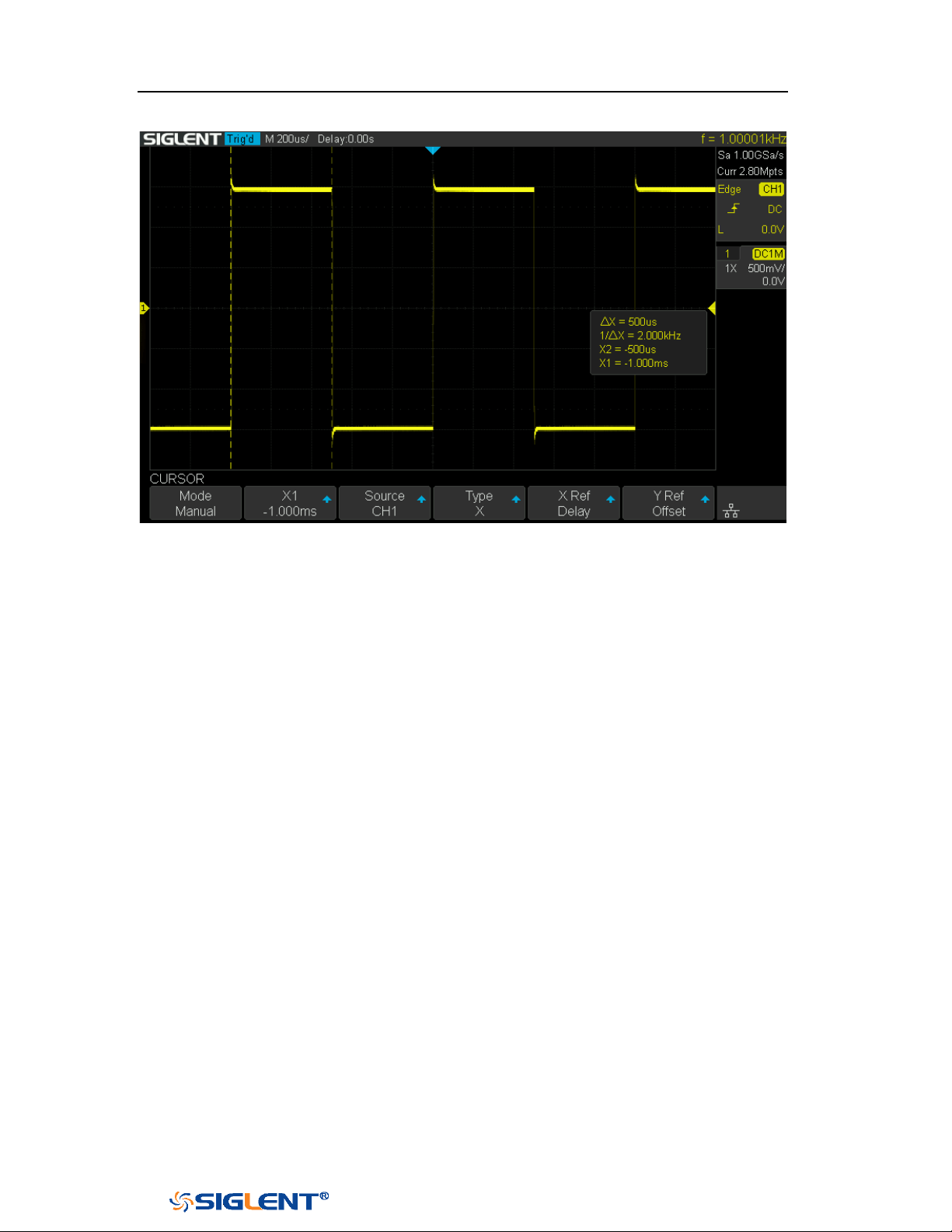
SDS1000X-E&SDS1000X-U User Manual
141
WWW.SIGLENT.COM
Figure 86 Measure Pulse Width

SDS1000X-E&SDS1000X-U User Manual
142
WWW.SIGLENT.COM
Measure
The oscilloscope provides measurements of 38 waveform parameters and the
statistics. It contains voltage, time and delay parameters.
Voltage and time parameters are under Type option. The results of the last four
selected measurements are displayed at the bottom of screen and above the menu.
Delay parameters are under the
All Measure submenu. Set the Delay option to On
to display all the delay parameters.
The contents of this chapter:
Type of measurement
Add measurement
Clear measurement
All measurement
Gate measurement
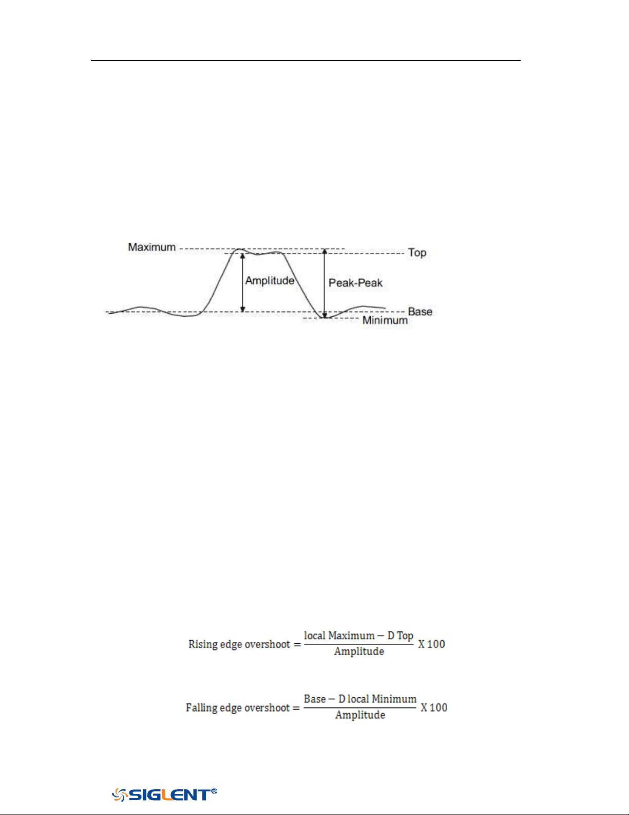
SDS1000X-E&SDS1000X-U User Manual
143
WWW.SIGLENT.COM
Type of Measurement
Voltage Measurements
Voltage measurements include 17 kinds of voltage parameter measurements.
Figure 87 Voltage Measurements
1.
Peak-Peak: Difference between maximum and minimum data values.
2. Maximum: Highest value in input waveform.
3. Minimum: Lowest value in input waveform.
4. Amplitude: Difference between top and base in a bimodal signal, or between
max and min in a unimodal signal.
5.
Top: Value of most probable higher state in a bimodal waveform.
6. Base: Value of most probable lower state in a bimodal waveform.
7. Mean: Average of all data values
8. Cycle mean: Average of data values in the first cycle.
9. Stdev: Standard deviation of all data values
10. Cycle Stdev: Standard deviation of all data values in the first cycle
11. Rms: Root mean square of all data values.
12. Cycle RMS: Root mean square of all data values in the first cycle.
13. Overshoot: Overshoot is distortion that follows a major edge transition
expressed as a percentage of Amplitude. ROV means rising edge overshoot
and FOV means falling edge overshoot.
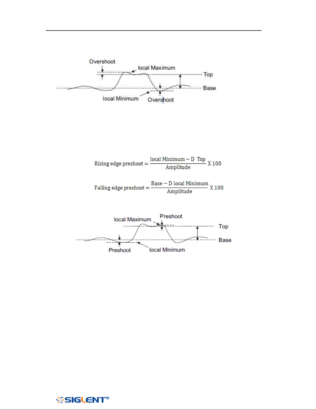
SDS1000X-E&SDS1000X-U User Manual
144
WWW.SIGLENT.COM
Figure 88 Overshoot
14. Preshoot: Preshoot is distortion that precedes a major edge transition
expressed as a percentage of Amplitude. The X cursors show which edge is
being measured (edge closest to the trigger reference point).
Figure 89 Preshoot
15. Level@X: the voltage value between the trigger point and the vertical position
of the channel
Time Measurements
Time measurements include 11 kinds of time parameter measurements.
SDS1000X-E&SDS1000X-U User Manual
145
WWW.SIGLENT.COM
Figure 90 Time Measurements
1. Period: Period for every cycle in waveform at the 50% level, and positive slope.
2.
Frequency: Frequency for every cycle in waveform at the 50% level ,and
positive slope
3. + Width: Width measured at 50% level and positive slope.
- Width: Width measured at 50% level and negative slope.
4. Rise Time: Duration of rising edge from 10-90%.
5. Fall Time: Duration of falling edge from 90-10%.
6. BWid: Time from the first rising edge to the last falling edge, or the first falling
edge to the last rising edge at the 50% crossing.
7. + Duty: Ratio of positive width to period.
- Duty: Ratio of negative width to period.
8. Delay:Time from the trigger to the first transition at the 50% crossing.
9. T@L: Time from trigger of each transition at a specific level and slope, include:
Current, Max, Min, Mean, and Std-dev.
Delay Measurements
Delay measurements measure the time different between arbitrary two channels,
including 10 kinds of delay measurements.
1. Phase: Calculate the phase difference between two edges.
2. FRFR: Time between the first rising edges of the two channels.
3. FRFF: Time from the first rising edge of channel A to the first falling edge of
channel B.
4.
FFFR: Time from the first falling edge of channel A to the first rising edge of
channel B.
5. FFFF: Time from the first falling edge of channel A to the first falling edge of
channel B.
6. FRLR: Time from the first rising edge of channel A to the last rising edge of
channel B.

SDS1000X-E&SDS1000X-U User Manual
146
WWW.SIGLENT.COM
7. FRLF: Time from the first rising edge of channel A to the last falling edge of
channel B.
8. FFLR: Time from the first falling edge of channel A to the last rising edge of
channel B.
9. FFLF: Time from the first falling edge of channel A to the last falling edge of
channel B.
10. Skew:Time of source A edge minus time of nearest source B edge.
SDS1000X-E&SDS1000X-U User Manual
147
WWW.SIGLENT.COM
Add Measurement
Perform the steps below and select voltage or time parameters to make automatic
measurement.
1. Press the
Measure button on the front panel to enter the MEASURE function
menu. At the same, the frequency and period are enabled with the current
trigger channel, the statistics also was enabled.
2. Press the Source softkey, and then use the Universal Knob to select the desired
channel. Only analog channels that are displayed are available for
measurements.
3. To select and display measurement parameters. Press the Type softkey, and
then turn the Universal Knob to select the desired measurement parameter.
4. Press the Universal Knob to add the measurement parameter, the parameters
and value will be shown above the menu, and the statistics status will update.
5. To turn off the statistic function, press the Statistics softkey to select Off.
The measurement display area can display 4 measurement parameters at most,
and the measurements will arrange according to the selecting order. If add the fifth
measurement parameter, it will delete the first measurement.
Figure 91 Select the Measurement Parameter
SDS1000X-E&SDS1000X-U User Manual
148
WWW.SIGLENT.COM
Figure 92 Added the Measurement
Note: if the parameter does not match the measure condition, it will display as
“****”.
SDS1000X-E&SDS1000X-U User Manual
149
WWW.SIGLENT.COM
Clear Measurement
SDS1000X-E (4-channel) supports selective clearing of measurement parameters
that are displaying on the screen. SDS1000X-E (2 channel) and SDS1000X-U only
support one key to clear all measurement items.
Figure 93 Clear Measurement
Press the Clear softkey to call up the clear measurement box. Rotate and press the
Universal Knob to clear a measurement or all measurement. Press Recover to
recover the selected measurement.
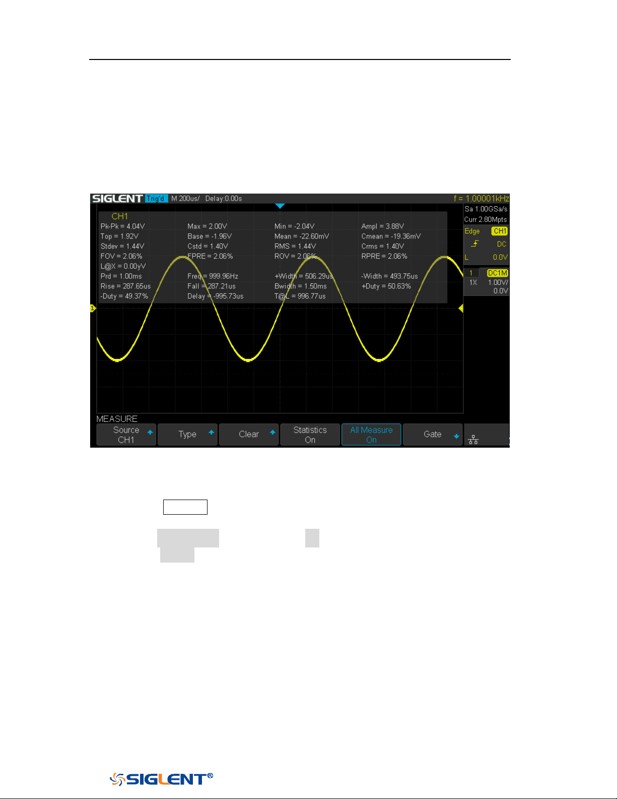
SDS1000X-E&SDS1000X-U User Manual
150
WWW.SIGLENT.COM
All Measurement
All measurement could measure all the voltage and time parameters of the current
measurement source and display the results on the screen.
Figure 94 All Parameters Measurement
Do the following steps to make all parameters measurement.
1. Press the Measure button on the front panel to enter the MEASURE function
menu.
2. Press the All Measure softkey to select On.
3. Press the Source softkey to select the measure source.
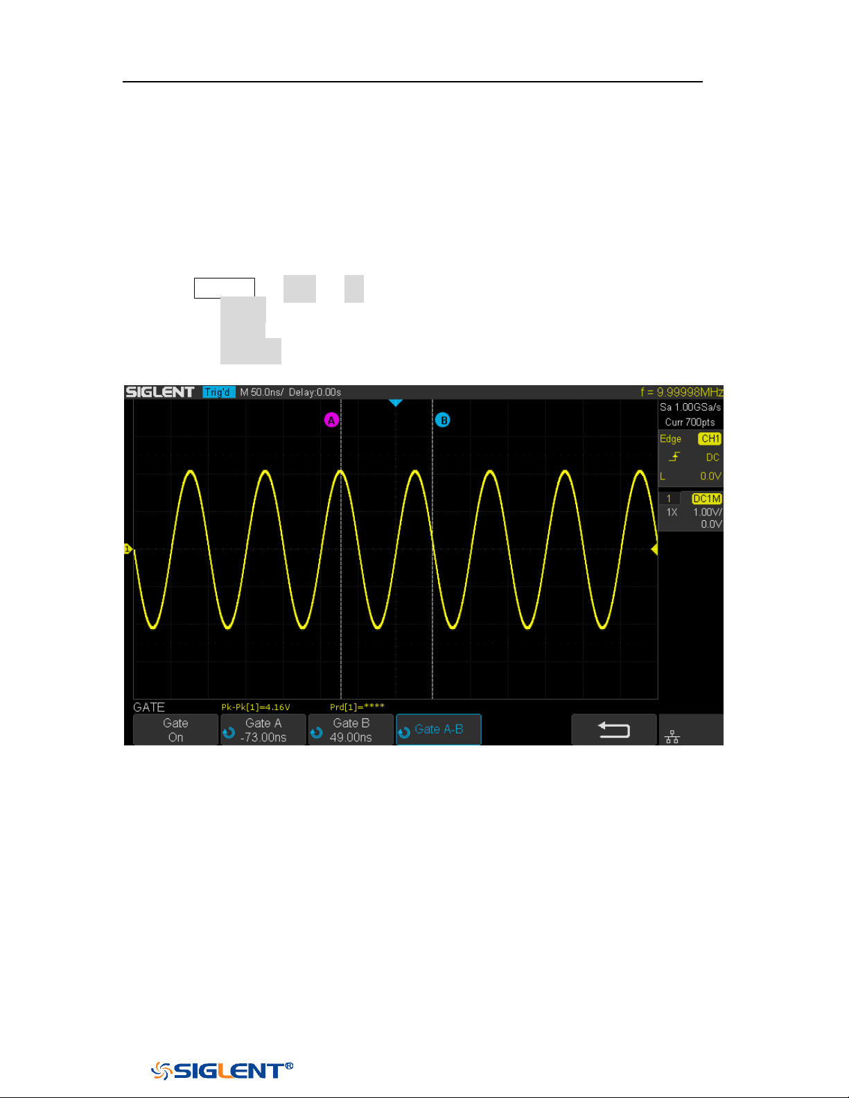
SDS1000X-E&SDS1000X-U User Manual
151
WWW.SIGLENT.COM
Gate Measurement
The SDS1000X-E/SDS1000X-U support gate measurement and perform the selected
measurement within the upper and lower limits of the gate. Setting the gate will
affect the measurement of all voltage, time, and delay parameters.
1. Press Measure → Gate → On to open the gate measurement.
2. Press the Gate A to move the position of gate A by the Universal Knob.
3. Press the Gate B to move the position of gate B by the Universal Knob.
4. Press the Gate A-B to move the positions of the gate A and B simultaneously by
the
Universal Knob.
Figure 95 Gate Measurement

SDS1000X-E&SDS1000X-U User Manual
152
WWW.SIGLENT.COM
Display
You can set the display type, color, persistence, grid type, waveform intensity, grid
brightness and transparence.
The contents of this chapter:
Display Type
Color Grade
Persistence
Clear the Display
Grid Type
Intensity
Grid Brightness
Transparence
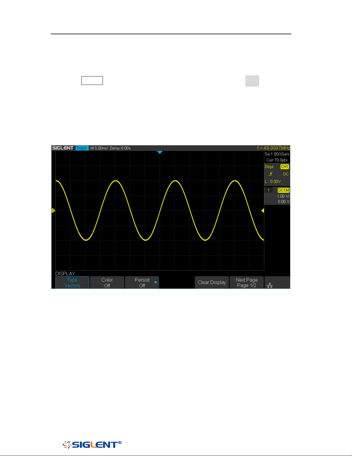
SDS1000X-E&SDS1000X-U User Manual
153
WWW.SIGLENT.COM
Display Type
Press the Display button on the front panel, and then press the Type softkey to
select Vectors or Dots display type.
Vectors: the sample points are connected by lines and displayed. Normally,
this mode can provide the most vivid waveform to view the steep edge of the
waveform (such as square waveform).
Dots: display the sample points directly. You can directly view each sample
point and use the cursor to measure the X and Y values of the sample point.
Figure 96 Vectors Display
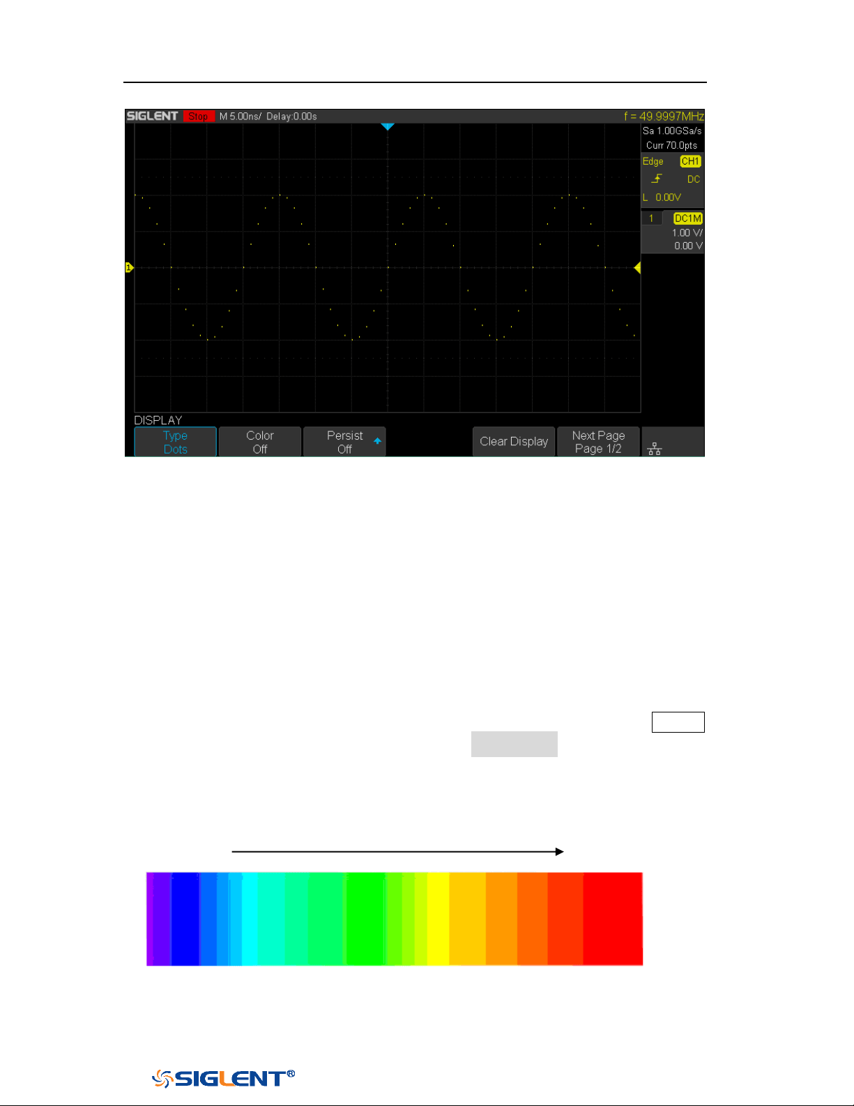
SDS1000X-E&SDS1000X-U User Manual
154
WWW.SIGLENT.COM
Figure 97 Dots Display
Color Grade
Color temperature adopts the change of waveforms’ color to reflect the change of
the waveforms’ appearing probability. The greater the probability that the
waveform appears, the warmer the color is; the smaller the waveform appears, the
colder the color is.
The picture below shows the change of color from cold to warm. Press the
Display
button on the front panel, and then press the Color Grade softkey and set the
option to On to turn on the color temperature function. You can compare the
waveform’s color with the picture below to just the probability that the waveform
appears.
Cold Color Warm Color
Figure 98 Color Temperature

SDS1000X-E&SDS1000X-U User Manual
155
WWW.SIGLENT.COM
Persistence
With persistence, the oscilloscope updates the display with new acquisitions, but
does not immediately erase the results of previous acquisitions. All previous
acquisitions are displayed with reduced intensity. New acquisitions are shown in
their normal color with normal intensity.
Do the following steps to set and clear persistence:
1. Press the
Display/Persist button on the front panel to enter the DISPLAY
function menu.
2. Press the Persist softkey; then turn the Universal Knob to select the desires
option.
Off —turn of persistence.
Variable persistence time (1 second, 5 seconds, 10 seconds, 30 seconds )
— select different persistence time, the results of previous acquisitions are
erased after a certain amount of time
Infinite —select “Infinite” Results of previous acquisitions are never
erased. Use infinite persistence to measure noise and jitter, to see the
worst- case extremes of varying waveforms, to look for timing violations,
or to capture events that occur infrequently.
Figure 99 Persist Set to Infinite
3. When the Persist is On, to erase the results of previous acquisitions from the
display, press the Clear Persist softkey. The oscilloscope will start to
SDS1000X-E&SDS1000X-U User Manual
156
WWW.SIGLENT.COM
accumulate acquisitions again.
4. To return to the normal display mode, turn off persist and the previous
acquisitions will be clear at once.
Clear Display
Press the Display button on the front panel to enter the DISPLAY function menu;
press the Clear Display softkey to clear all the waveforms displaying on the screen
and acquire and display new waveforms.
Grid Type
To select grid type
1. Press the
Display/Persist button on the front panel to enter the DISPLAY
function menu.
2. Press the Next Page softkey to go to the second page of the Display function
menu.
3. Press the Grid softkey; and then turn the Universal Knob to select the desired
grid type. Press the Grid softkey continually can also select the grid type.
There are 3 kinds of grid types that are available. Select the grid type according to
your really demand.
Display 14X8 grid type
Display 2X2 grid type
Display without grid
Intensity
Do the following steps to adjust waveform intensity:
1. Press the
Display/Persist button on the front panel to enter the DISPLAY
function menu.

SDS1000X-E&SDS1000X-U User Manual
157
WWW.SIGLENT.COM
2. Press the Next Page softkey to go to the second page of the Display function
menu.
3. Press the Intensity softkey; and then turn the Universal Knob to select the
desired value. The default value is 50%, and the range is from 0% to 100%.
Increasing the intensity lets you see the maximum amount of noise and
infrequently occurring events. Reducing the intensity can expose more detail in
complex signals as shown in the following figures.
Grid Brightness
Do the following steps to adjust the grid brightness:
1. Press the
Display button on the front panel to enter the DISPLAY function
menu.
2. Press the Next Page softkey to go to the second page of the Display function
menu.
3. Press the Graticule softkey; and then turn the Universal Knob to select the
desired value. The default value is 40%, and the range is from 0% to 100%.
Transparence
Transparence can be used to adjust the transparence of the message box of cursor,
measure, Pass/Fail and all pop-up menus to an appropriate value to observe the
date more conveniently.
Under Cursor or Measure or any other menu operation, if want to change the
transparence of the message box, do the following steps:
1. Press the
Display button on the front panel to enter the DISPLAY function
menu.
2. Press the Next Page softkey to go to the second page of the Display function
Note: Waveform intensity adjustment affects analog channel waveforms only
(not math waveforms, reference waveforms, digital waveforms, etc.).

SDS1000X-E&SDS1000X-U User Manual
158
WWW.SIGLENT.COM
menu.
3. Press the Transparence softkey; and then turn the Universal Knob to select the
desired value. The default value is 80%, and the range is from 20% to 80%.

SDS1000X-E&SDS1000X-U User Manual
159
WWW.SIGLENT.COM
Save and Recall
Oscilloscope setups, waveforms, pictures, and CSV files can be saved to internal
oscilloscope memory or to a USB storage device. The saved setups, waveforms can
be recalled later. The oscilloscope provides an USB Host interface on the front
panel to connect an USB device for external storage.
The contents of this chapter
Save Type
Internal Save and Recall
External Save and Recall
Disk Management

SDS1000X-E&SDS1000X-U User Manual
160
WWW.SIGLENT.COM
Save Type
The oscilloscope supports setups, waveforms, images and CSV files storage. The
default save type is setups.
1. Setups
It’s the default storage type of the oscilloscope. It saves the settings of the
oscilloscope in internal or external memory in “*.xml” format. At most 20 setting
files (from No.1~No.20) can be stored in internal memory. The stored settings can
be recalled.
2. Reference
The oscilloscope saves the waveform data in external memory in “*.REF” format.
The data of the channel is you select channel. At recall, the data will be displayed
on the screen by REFA or REFB.
3. BMP
The oscilloscope saves the screen image in external memory in “*.bmp” format.
You can specify the file name and saving directory under the same directory using
the same file name. The recall of image is not supported.
4. JPG
The oscilloscope saves the screen image in external memory in “*.jpg” format.
You can specify the file name and saving directory under the same directory using
the same file name. The recall of image is not supported.
5. PNG
The oscilloscope saves the screen image in external memory in “*.png” format.
You can specify the file name and saving directory under the same directory using
the same file name. The recall of image is not supported.
6. Binary
The oscilloscope saves the waveform data in external memory in “*.BIN” format.
The data of all the channels turned on can be saved in the same file. The recall of
binary is not supported.
7. CSV
The oscilloscope saves the waveform data in external memory in “*.CSV” format.
The stored files contain the waveform data of the displayed analog channels and
the main setting information of the oscilloscope. The recall of CSV file is not
supported.

SDS1000X-E&SDS1000X-U User Manual
161
WWW.SIGLENT.COM
Set the save type to CSV, and set the Param Save option to On or Off to turn on or of
the parameters storage function.
8. Matlab
The oscilloscope saves the waveform data in external memory in “*.DAT” format.
The data of all the channels turned on can be saved in the same file. The recall of
Matlab file is not supported.
9. To Default Key
The oscilloscope saves the factory config and user set config. Then you can select
the default function is the factory config or user set config.
10. FileConverter
The mini tool is used to convert stored binary files to CSV format for viewing with a
spreadsheet program. It supports for file of waveform data (*.bin), file of sample
logger(*.slg) and file of measure logger (*.mlg) to convert.
This is ideal when collecting large datasets. For a waveform frame with deep
memory such as 14 Mpts, to save directly as a CSV file will take long time and will
occupy a large amount of memory on a USB storage device. It’s recommended to
save the data as binary file and then convert it to CSV file on a computer.
SDS1000X-E&SDS1000X-U User Manual
162
WWW.SIGLENT.COM
Note: if need to delete a setup file in the memory, please save a new setup to the
same location to overwrite it.
Internal Save and Recall
Internal save and recall support Setups in
Save/Recall. In the following part, the
save and recall method and procedures are introduced.
Save the specified oscilloscope setting in internal memory.
1. Connect the signal to the oscilloscope and obtain stable display.
2. Press Save/Recall button on the front panel to enter the SAVE/RECALL
function menu.
3. Press the Save softkey to enter the SAVE function menu.
4. Press the Type softkey and then turn the Universal Knob to select Setups;
and then press the knob to confirm.
5. Press the Save to softkey to select Internal to save the current setup of the
oscilloscope to the internal memory.
6. Press the Setup softkey button; and then turn the Universal Knob to select
the location to save. The internal memory can save as many as 20 setup
files, from No.1~No.20.
7. Press the Press to Save softkey to save the current setup to the appointed
location. After a few seconds, it will pop-up the message “Saved to
internal file NO.x!”
Load the specified type of file in internal memory.
If want to recall the setup after having finished the steps above, please do the
following steps:
1. Press the Recall softkey enter the RECALLING function menu.
2. Press the Type softkey and then turn the Universal Knob to select Setups;
and then press the knob to confirm.
3. Press the Recall from softkey to select Internal.
4. Press the Setup softkey button; and then turn the Universal Knob to select
the location to recall. The internal memory can recall as many as 20 setup
files, from No.1~No.20.
5. Press the Press to Recall softkey to recall the current setup form the
appointed location. After a few seconds, it will pop-up the message
“Recalled file successfully!”
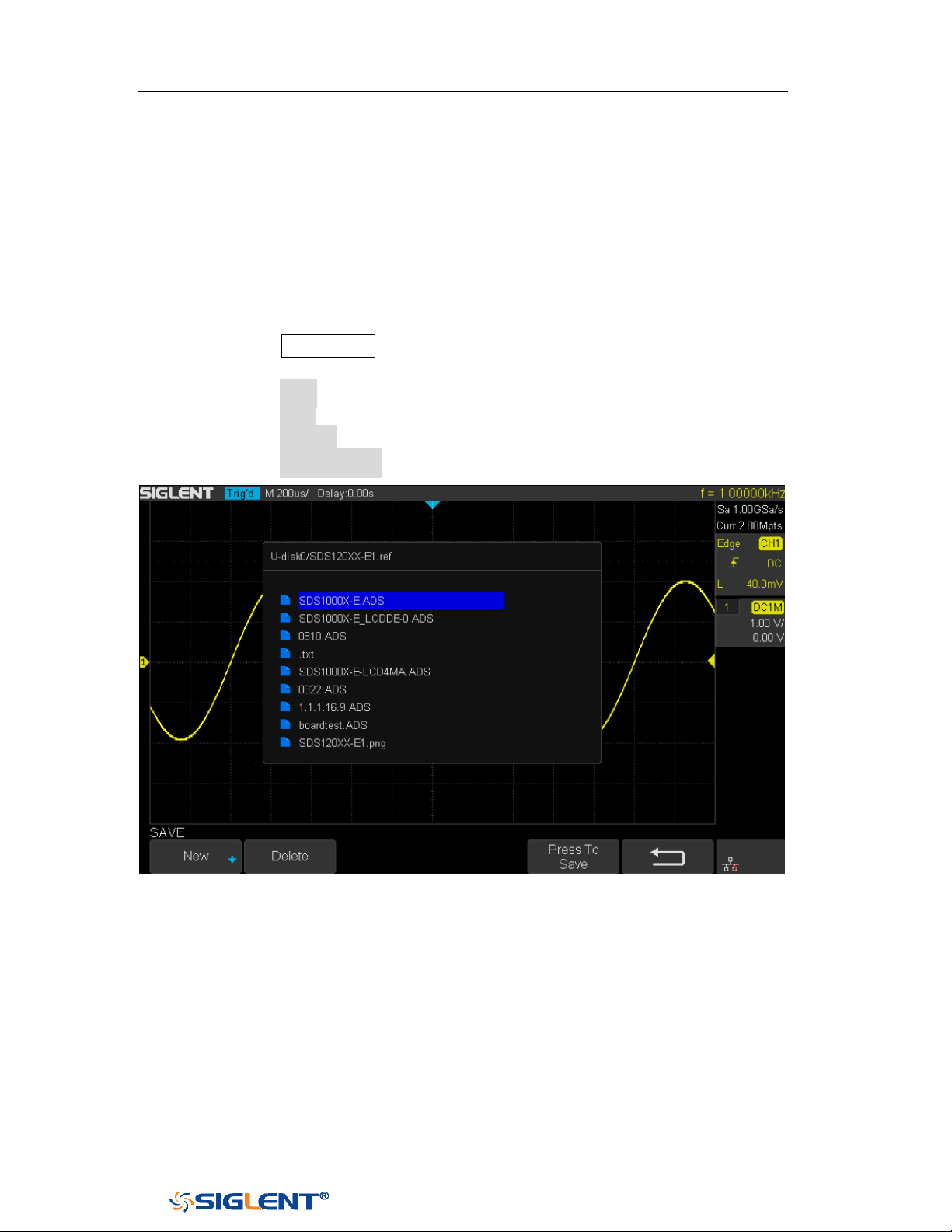
SDS1000X-E&SDS1000X-U User Manual
163
WWW.SIGLENT.COM
External save and recall
Before using external storage and recall, make sure that the USB flash device is
connected correctly. External storage supports all the types of files in save
, but in
recall, images and CSV are not supported.
Save the specified type of file in the external USB flash device.
1. Press the Save/Recall button on the front panel to enter the SAVE/RECALL
function menu.
2. Press the Save softkey to enter the SAVE menu.
3. Press the Type softkey to select Setup and then press the knob to confirm.
4. Press the Save to softkey to select External.
5. Press the Press to Save softkey to enter the SAVE/RECALL file system.
Figure 100 SAVE/RECALL File System
6. Use the
Universal Knob to select the desired location. File can be stored
under the root directory or in a certain folder under the root directory of
the USB storage device.
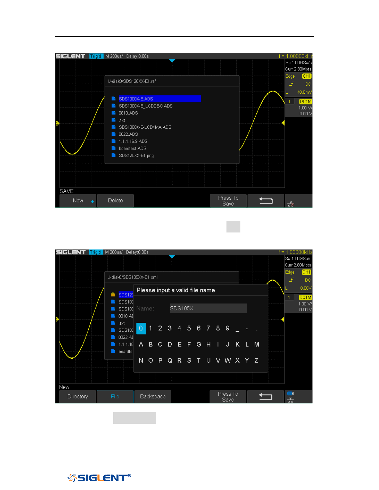
SDS1000X-E&SDS1000X-U User Manual
164
WWW.SIGLENT.COM
Figure 101 Select Save Location
7. After the save position is selected, press the New softkey to turn on the
interface as shown in the figure below. Refer to the descriptions in “To
Create a new file or fold” to create a new file name.
Figure 102 File Name Dialogue
8. Press the Press to Save softkey to save the current setup to the external
USB storage device.

SDS1000X-E&SDS1000X-U User Manual
165
WWW.SIGLENT.COM
Load the specified type of file in the external USB storage device.
1. Press the Save/Recall button on the front panel to enter the SAVE/RECALL
function menu.
2. Press the Recall softkey to enter the RECALL menu.
3. Press the Type softkey to select Setups or Reference.
4. Press the Recall from softkey to select External.
5. Press the Press to Recall softkey to enter the SAVE/RECALL file system.
6. Turn the Universal Knob to select the file to be recalled, press the Press to
Recall softkey to recall the reference or setup.

SDS1000X-E&SDS1000X-U User Manual
166
WWW.SIGLENT.COM
Disk Management
Disk management aim at the save and recall operations after the oscilloscope is
connected with a USB storage device. Before using external disk, make sure that
the USB storage device is connected correctly.
Execute the following operations through the disk management menu:
Create a New File or Folder
Delete a File or Folder
Rename a File or Folder
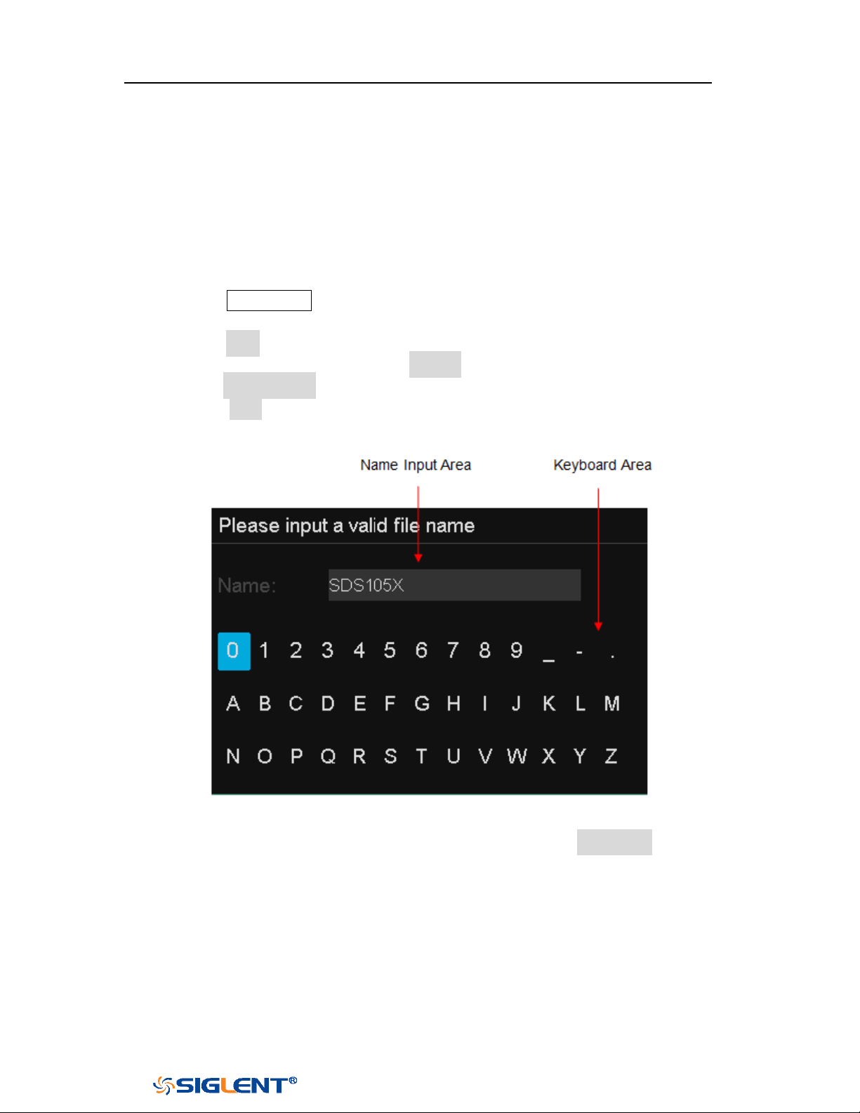
SDS1000X-E&SDS1000X-U User Manual
167
WWW.SIGLENT.COM
Create a New File or Folder
This operation is only valid in external storage. The oscilloscope supports English
input method. The file name or folder name can contain letters, numbers,
underscores and spaces. Let’s use an example to introduce how to create a file or
folder.
Example: create a file or folder named “SDS105X”
1. Press the Save/Recall button on the front to enter the SAVE/RECALL function
menu.
2. Press the Save softkey, and then turn the Universal Knob to select one of the
type (if select Setups, please set the Save to option to External).
3. Press the Press to Save softkey to enter the SAVE/RECAL file system.
4. Press the New softkey to open the interface shown as the figure below. It
divides into two parts: name input area and keyboard area.
Figure 103 Input Keyboard
5. To delete the name in the name input area, press the Backspace softkey
continuously to delete the character one by one.

SDS1000X-E&SDS1000X-U User Manual
168
WWW.SIGLENT.COM
Delete a File or Folder
This operation is only valid in external storage.
1. Press the Save/Recall button on the front to enter the SAVE/RECALL function
menu.
2. Press the Save softkey, and then turn the Universal Knob to select one of the
type (if select Setups, please set the Save to option to External).
3. Press the Press to Save or Press to Recall softkey to enter the SAVE/RECAL file
system.
4. Turn the Universal Knob to select the file or folder to be deleted, and then press
the Delete softkey. Then the file or folder will be deleted.
Rename a File or Folder
This operation is only valid with external storage (U disk storage), and only files of
the corresponding type format can be renamed.
1. Press the Save/Recall button on the front to enter the SAVE/RECALL function
menu.
2. Press the Save softkey, and then turn the Universal Knob to select one of the
type (if select Setups, please set the Save to option to External).
3. Press the Press to Save or Press to Recall softkey to enter the SAVE/RECAL file
system.
4. Turn the
Universal Knob to select the file or folder to be rename, and then
press the Rename softkey. For details, see the instructions in "Create a New File
or Folder."

SDS1000X-E&SDS1000X-U User Manual
169
WWW.SIGLENT.COM
Digital Channels(Option)
This chapter describes how to use the digital channels of a Mixed-Single
Oscilloscope (MSO).
The digital channels are enabled on SDS1000X-E (4-channel scope) that have
installed the MSO activation license. As an external module, SLA1016 is
independent of the host, and has its own system, so it needs to be upgraded if
necessary.
This chapter contains the following items:
Connect the Digital Probes
Acquire Digital Waveform
Digital Channels Height
Digital Channels Position
Single Digital Channel
All Digital Channels
Logic Threshold
Digital Bus
Deskew
System Setting
Remove Device

SDS1000X-E&SDS1000X-U User Manual
170
WWW.SIGLENT.COM
Note:
There are two indicators on the side of the SLA1016, one is red (Power),
another is green (Ready)
The red indicator: If SLA1016’s power is normal, this indicator turns on,
or else it blinks or turns off.
The green indicator: When the SLA1016 is connect to the oscilloscope,
this indicator turns on for seconds then turns off, and then blinks, and
finally keeps the light on. When data is transferred between the
SLA1016 and the oscilloscope, the indicator blinks.
Connect the Digital Probes
1. If necessary, turn off the power supply to the device-under-test.
Turning off the power to the device-under-test prevents damage that
might occur if you accidentally short lines together while connecting
probes. You can leave the oscilloscope powered on because no voltage
appears at the probes.
2. Connect one of the digital probe cable ports to the digital channels connector
on the front panel of the SDS1000X-E, and the other one to the digital channels
connector of the digital probe.
The digital probe cable is keyed so you can connect it only one way. You
do not need to power-off the oscilloscope.
3. Connect a fly line to one of the digital probe ground pins, connect a grabber to
the fly line, and then connect the grabber to a ground trace/pin from the
device-under-test. The ground lead improves signal fidelity to the oscilloscope,
ensuring accurate measurements,
4. Connect a fly line to one of the digital probe digital channel pins; connect a
grabber to the fly line, and then connect the grabber to a node in the circuit you
want to test.
5. Repeat step 4 until you have connected all points of interest.
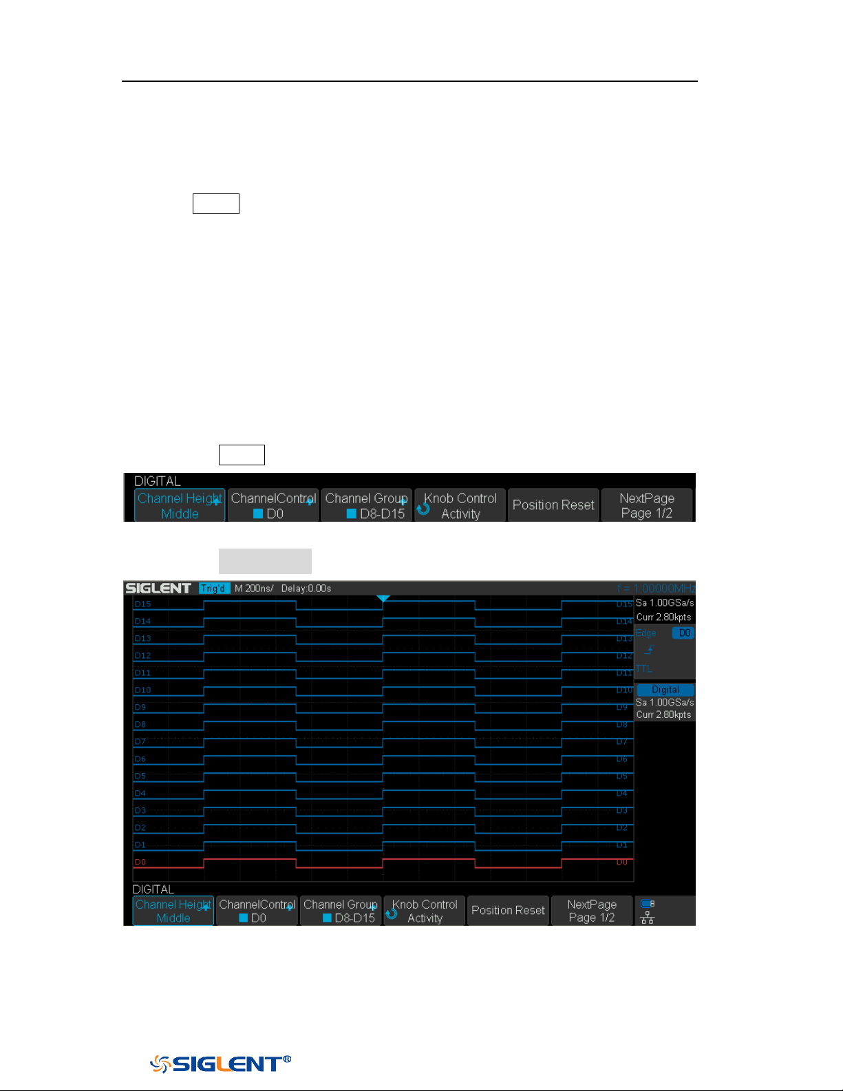
SDS1000X-E&SDS1000X-U User Manual
171
WWW.SIGLENT.COM
Acquire Digital Waveform
Press the
Digital button on the front panel to open the digital channels and start
acquiring digital channel waveforms.
For digital channels, each time the oscilloscope takes a sample it compares the
input voltage to the logic threshold. If the voltage is above the threshold, the
oscilloscope stores a 1 in the sample memory; otherwise, it stores a 0.
Digital Channels Height
1. Press the
Digital button on the front panel to open the DIGITAL function menu.
Figure 104 Digital Function Menu
2. Press the Channel High softkey to select Low, Middle, High display type.
Figure 105 Middle Display Type
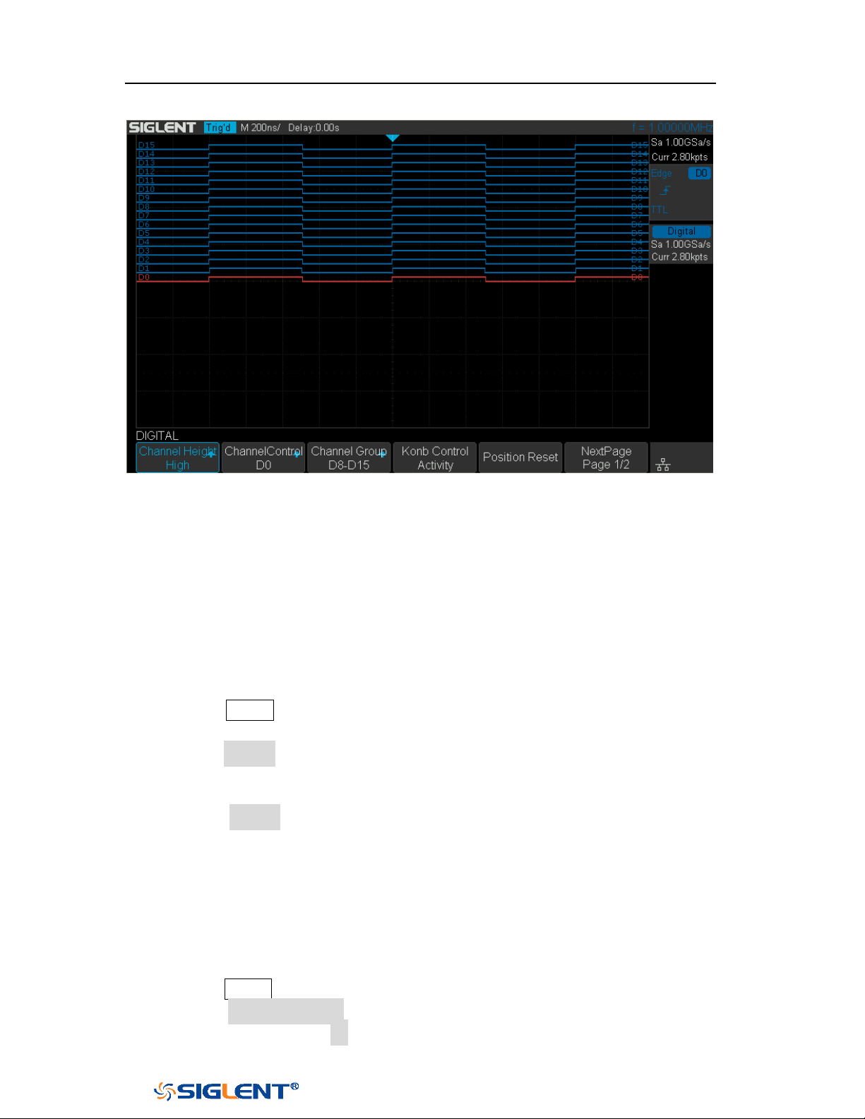
SDS1000X-E&SDS1000X-U User Manual
172
WWW.SIGLENT.COM
Figure 106 High Display Type
The display type control lets you spread out or compress the digital traces vertically
on the display for more convenient viewing.
Digital Channels Position
1. Press the
Digital button on the front panel to open the DIGITAL function menu
and display the digital channel waveforms.
2. Press the Control softkey select the Active then turn the Universal Knob to select
the channel that you wish to reposition. The selected waveform is highlighted
in red.
3. Press the Control softkey select the Position then turn the Universal Knob to
move the selected channel to any position.
Single Digital Channel
1. Press the
Digital button on the front panel to open the DIGITAL function menu.
2. Press the Channel Control softkey, then turn the Universal Knob to select the
desired channel such as Dx and push down the knob to confirm.
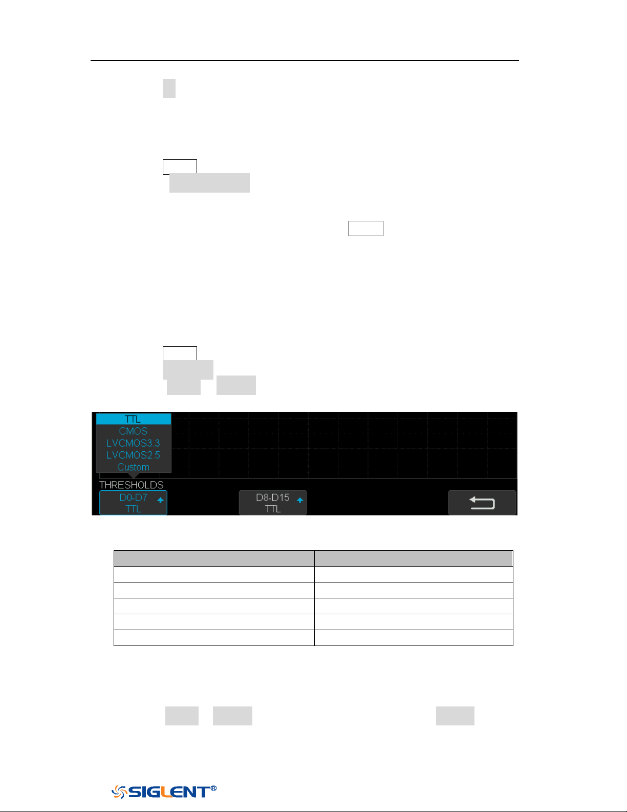
SDS1000X-E&SDS1000X-U User Manual
173
WWW.SIGLENT.COM
3. Press the Dx softkey to select On or Off to switch the selected channel on or off.
All Digital Channels
1. Press the
Digital button on the front panel to open the DIGITAL function menu.
2. Press the Channel Group softkey to select On or Off to switch all digital
channels which in this group on or off.
Also, under the DIGITAL function menu, press the Digital button on the front panel
to switch all digital channels off.
Logic Threshold
1. Press the
Digital button on the front panel to open the DIGITAL function menu.
2. Press the Threshold softkey to enter the THRESHOLDS menu.
3. Press the D0~D7or D8~D15softkey, then turn the Universal Knob to select a
logic family preset or select Custom to define your own threshold.
Figure 107 THRESHOLDS Function Menu
Logic Family
Threshold Voltage
TTL
1.5V
CMOS
1.65V
LVCMOS3.3
1.65V
LVCMOS2.5
1.25V
Custom
Variable from -3V to +3V
The threshold you set applies to all channels.
Values greater than the set threshold are high (1) and values less than the
set threshold are low (0).
If the D0~D7or D8~D15 softkey is set to Custom, press the Custom softkey,
then turn the Universal Knob to select the desired value and push down
the knob to confirm.
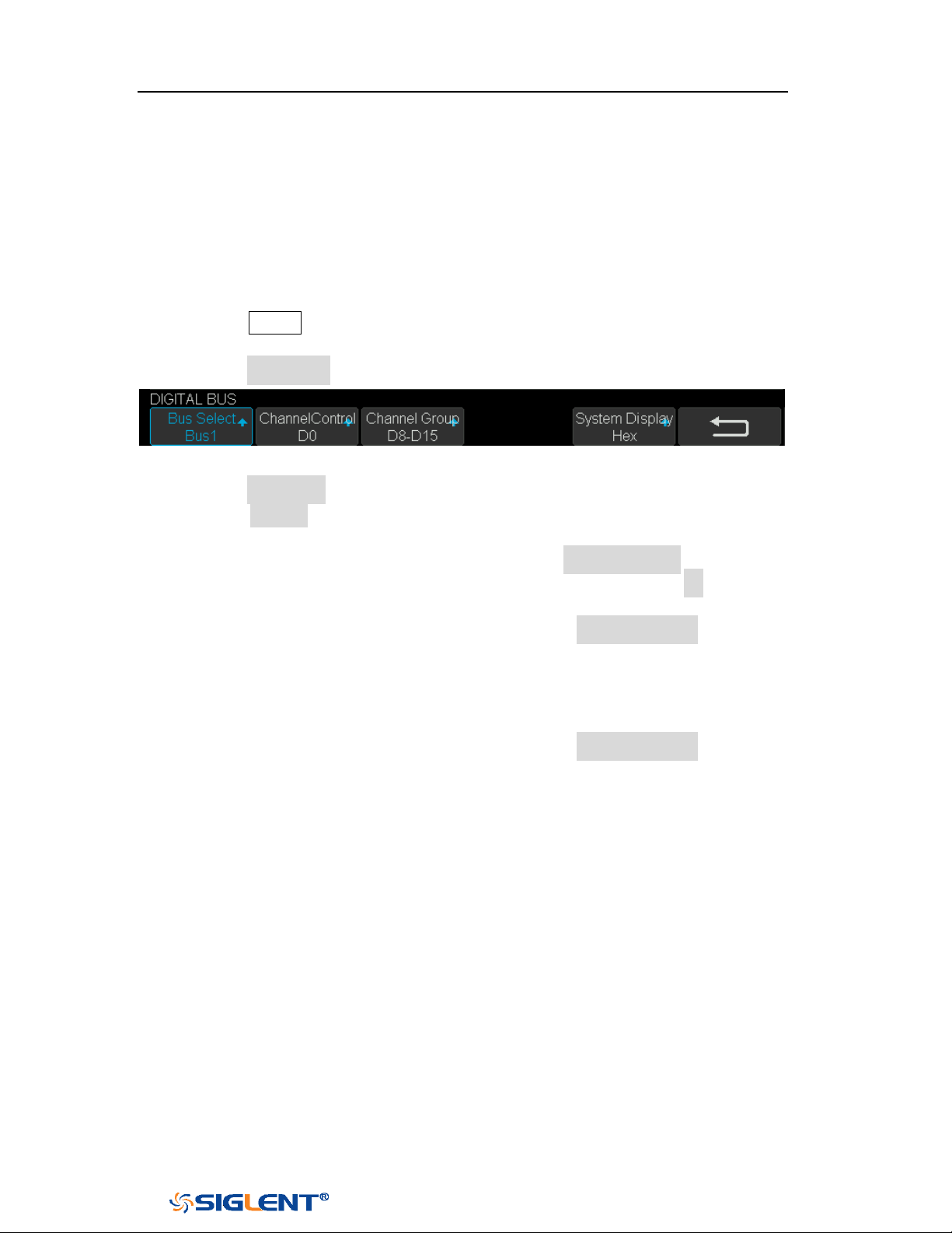
SDS1000X-E&SDS1000X-U User Manual
174
WWW.SIGLENT.COM
Digital Bus
Digital channels may be grouped and displayed as a bus, with each value
displayed at the bottom of the display in hex or binary. You can create up two
buses.
To configure and display each bus, do the following steps:
1. Press the
Digital button on the front panel to open the DIGITAL function menu
and display the digital channel waveforms.
2. Press the Digital Bus softkey to enter the DIGITALBUS function menu.
Figure 108 DIGITALBUS Function Menu
3. Press the Bus Select softkey to select Bus1 or Bus 2.
4. Press the Display softkey to select On to display the bus at the bottom of the
display.
Under the DIGITAL function menu, press the Cannel Control softkey, turn
the Universal Knob to select such as DX, and then press the Dx softkey to
select On or Off to set the channel to be included or excluded in the bus.
Under the DIGITAL function menu, press the Channel Group softkey to
select On or Off to include or exclude all digital channels in this group.
Under the DIGITAL function menu, a status indicator is displayed in the
status line at the bottom of the display. Light blue shows the digital
channel is included in the bus while black shows it is excluded in the bus.
Under the DIGITAL function menu, press the System Display softkey to
select Binary or Hex to display the bus values.
The Sampling rate of digital channels is displayed at the right of the display.
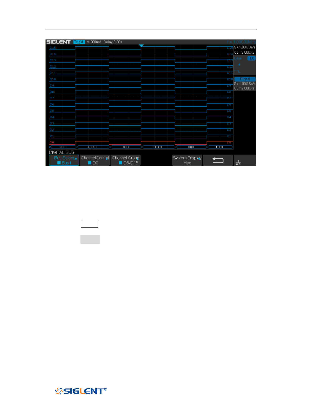
SDS1000X-E&SDS1000X-U User Manual
175
WWW.SIGLENT.COM
Figure 109 Digital Bus
Deskew
1. Press the
Digital button on the front panel to open the DIGITAL function menu
and display the digital channel waveforms.
2. Press the Deskew softkey, and then turn the Universal Knob to select to change
deskew.
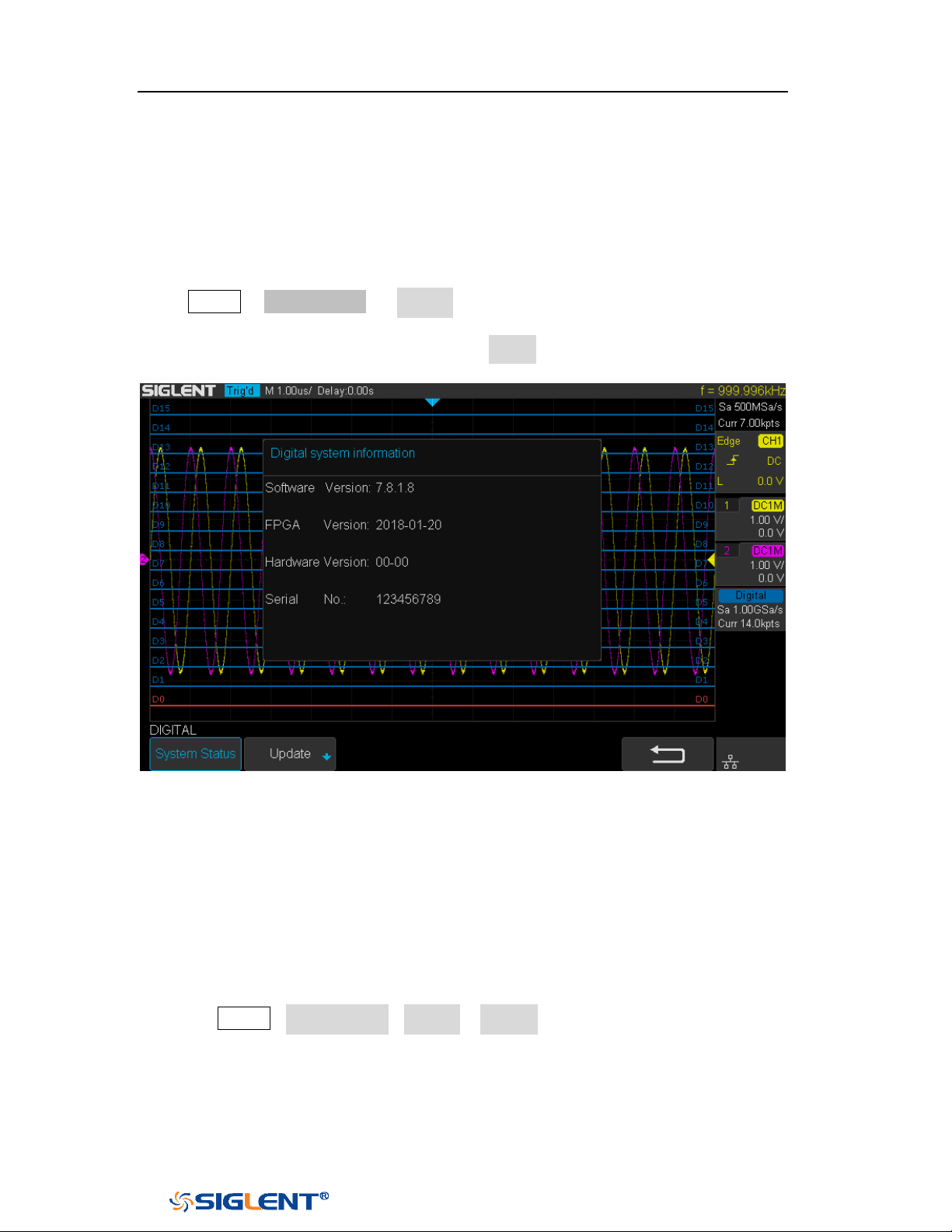
SDS1000X-E&SDS1000X-U User Manual
176
WWW.SIGLENT.COM
System Setting
System Status
Press Digital→ NextPage2/2 → System ,then select the System Status option to
view the digital system information , including software version, hardware version,
and serial number. After finished, press the return soft key to quit the interface of
system information.
Figure 110 Digital System Information Interface
Update
The software version file of the Digital can be updated directly via U-disk. Follow
the steps below:
1. Insert U-disk with firmware update file (*.ads) to USB host interface on the front
panel of the oscilloscope. Then a message “USB Flash Drive detected!” will
be displayed.
2. Press Digital→NextPage2/2→System →Update
3. Expand the U disk directory, Select the firmware file (*.ads), then press the
Press to update, an upgrade progress bar will be display on the interface.
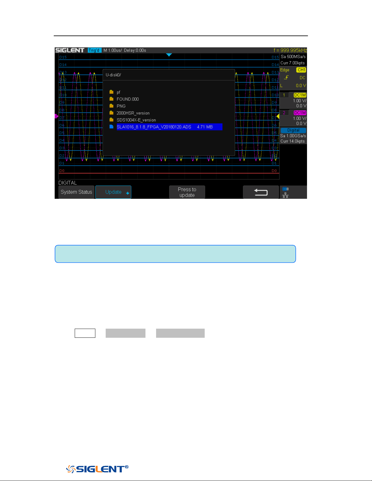
SDS1000X-E&SDS1000X-U User Manual
177
WWW.SIGLENT.COM
Figure 111 Digital Update Interface
4. After the updating is finished, the Digital device will automatically
disconnected and display a message “
Update completed, please reconnect
Digital device!”
Remove Device
Press Digital→ NextPage2/2 →Remove Device and the oscilloscope interface
display "Digital device removed!", the device can be pulled.
Note:Don't cut off the power during the Digital device is being updated!

SDS1000X-E&SDS1000X-U User Manual
178
WWW.SIGLENT.COM
System Setting
This function module supports the oscilloscope’s system-related function, such as
system status, language, sound and some other advanced setting, such as do
self-cal, update and remote interface configure.
The contents of this chapter:
View System Status
Do Self Cal
Quick-Cal
Sound
Language
Pass/Fail Test
Arbitrary Waveform Generator(Option)
IO Set
Web Server
Counter
Data Logger
Update Firmware and configuration
Do self-Test
Screen Saver
Date/Time
Reference Position
Power On Line
Option Management
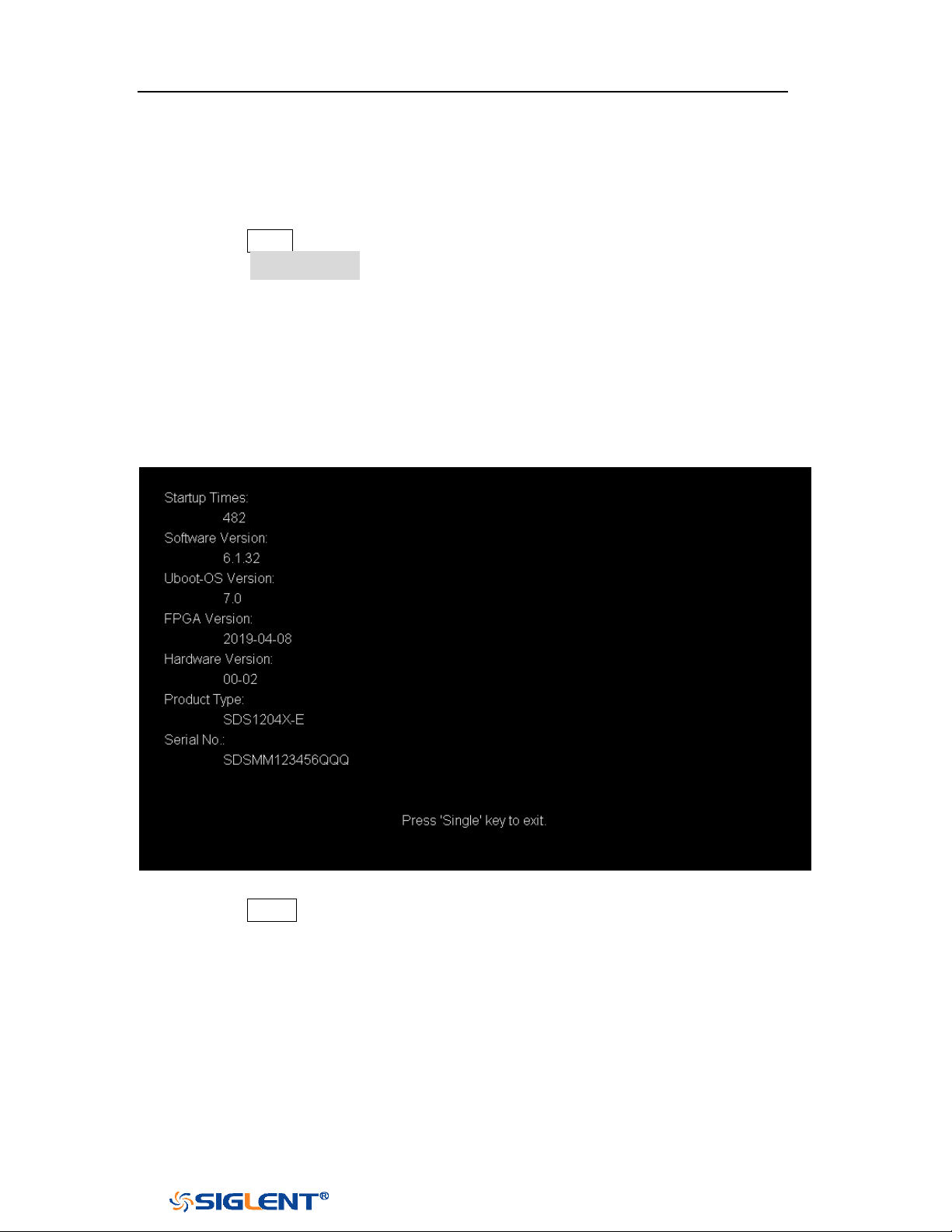
SDS1000X-E&SDS1000X-U User Manual
179
WWW.SIGLENT.COM
View System Status
Do the following steps to view the system status:
1. Press the
Utility button on the front to enter the UTILITY function menu.
2. Press the System Status softkey to view the system status of the oscilloscope.
The system status includes the information below:
Startup Times: record the boot-strap times of the oscilloscope.
Software Version: list the current software version of the oscilloscope.
Uboot-OS Version: list the current Uboot and OS version of the oscilloscope
FPGA Version: list the current fpga version of the oscilloscope.
Hardware Version: list the current hardware version of the oscilloscope.
Product Type: display the product type of the oscilloscope.
Serial No.: list the serial number of the oscilloscope.
Figure 112 System Status
3. Press the Single button on the front panel to exit.
Do Self Cal
The self-calibration program can quickly make the oscilloscope reach the best
working state to get the most precise measurement values. You can perform
self-calibration at any time especially when the change of the environment
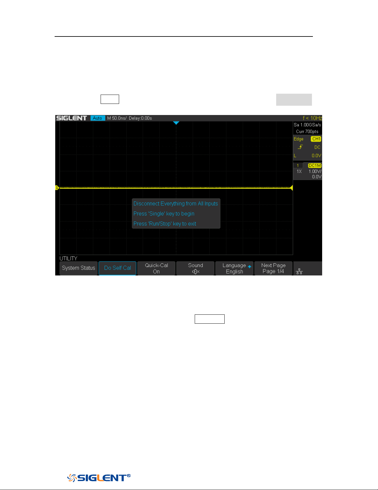
SDS1000X-E&SDS1000X-U User Manual
180
WWW.SIGLENT.COM
temperature is up to or more than 5 ℃. Make sure that the oscilloscope has been
warmed up or operated for more than 30 minutes before the self-calibration.
Do the following steps to do self-calibration:
1. Disconnect all the input channels.
2. Press the Utility button on the front panel,and then press the Do Self Cal
softkey, and the oscilloscope will pop-out the message box shown as below:
Figure 113 Do Self Cal
3. Press the Single button on the front panel to perform the self-calibration
program. During the calibration, most of the keys are disabled.
4. When the self-calibration program is finished, it will pop-out the message
“
Press Run/Stop key to exit”. Press the Run/Stop button on the front panel to
exit the calibration interface.
SDS1000X-E&SDS1000X-U User Manual
181
WWW.SIGLENT.COM
Quick-Cal
Quick calibration can correct the measurement deviation caused by temperature,
so that you can get more accurate measurements.
If the ambient temperature of your current operating oscilloscope is unstable, press
Utility → Quick-Cal softkey to select On to enable quick calibration.
Sound
When the sound is enabled, you can hear the sound of the beeper when you press
a function key or a menu softkey or when the prompt message pops up.
Press the
Utility button on the front panel to enter the UTILITY function menu; then
press Sound softkey to select or to turn on or off the sound.
Language
The oscilloscope supports multiple language menu, Chinese/English help and
prompt messages.
1. Press the
Utility button on the front panel to enter the UTILITY Function menu.
2. Press the Language softkey; and then turn the Universal Knob to select the
desired language. Then push down the knob to select the language.
The languages that currently available are Simplified Chinese, Traditional Chinese,
English, French, German, Spanish, Russian, Italian, and Portuguese.
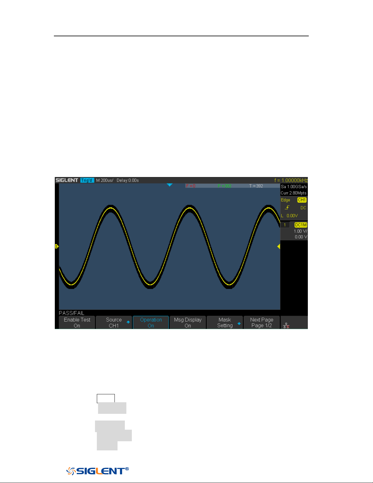
SDS1000X-E&SDS1000X-U User Manual
182
WWW.SIGLENT.COM
Pass/Fail Test
One way to verify a waveform's compliance to a particular set of parameters is to
use pass/fail testing. A pass/fail defines a region of the oscilloscope's display in
which the waveform must remain in order to comply with chosen parameters.
Compliance to the mask is verified point- by- point across the display.
The test results can be displayed on the screen as well as be declared through the
system sound or the pulse signal output from the
[TRIG OUT] connector at the rear
panel. Pass/Fail test operates on displayed analog channels; it does not operate
on channels that are not displayed.
Figure 114 Pass/Fail Test
Set and Perform Pass/Fail Test
Do the following steps to set and perform pass/fail test:
1. Press the
Utility button on the front panel to enter the UTILITY function menu.
2. Press the Next Page softkey to go to the second page of the UTILITY function
menu.
3. Press the Pass/Fail softkey to enter the PASS/FAIL function menu.
4. Press the Enable Test softkey to select On to enable the pass/ fail test.
5. Press the Source softkey to select the desired channel.
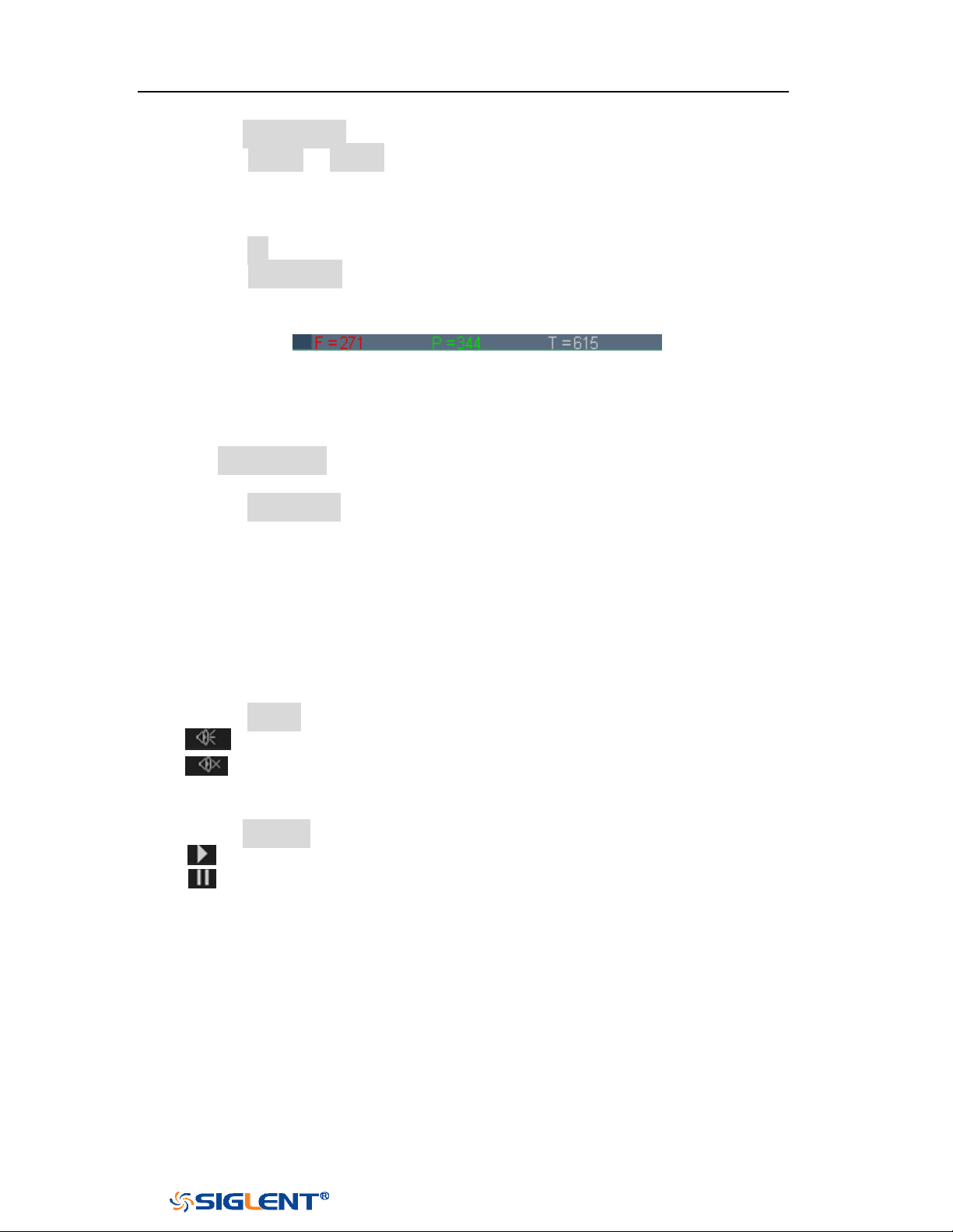
SDS1000X-E&SDS1000X-U User Manual
183
WWW.SIGLENT.COM
6. Press the Mask Setting softkey to enter the MASK function menu.
7. Press the X Mask or Y Mask softkey; and then turn the Universal Knob to select
the desired value. The range is from 0.02div to 4div.
8. Press the Create Mask button to create the mask. Whenever the Create Mask
softkey is pressed the old mask is erased and a new mask is created.
9. Press the UP softkey to return to the PASS/FAIL function menu.
10. Press the Msg Display to select On or Off to turn on or off the message display.
When On is selected, the test result will be displayed in the upper-right
message box of the screen.
F: the frame number of the channel waveform that fails to match the mask.
P: the frame number of the channel waveform that matches the mask.
T: the frame number of the channel waveform that have been acquired. It
is the total of Pass and Fail.
11. Press the Next Page softkey to go to the second page of the PASS/FAIL function
menu.
12. Press the Stop On Fail softkey to select On or Off to turn on or off the function.
On: when failed waveforms are detected, the oscilloscope will stop the test
and enter the STOP state. At this point, the results of the test remain the
same on the screen (if display is turned on) and only one pulse is output
from the [TRIG OUT] connector (if enabled) at the rear panel.
Off: the oscilloscope will continue with the test even though failed
waveforms are detected. The test results on the screen will update
continuously and a pulse will be output from the [Trigger Out] connector at
the rear panel each time a failed waveform is detected.
13. Press the Output softkey to select turn on or off the sound.
: When the failed waveforms are detected, the beeper sounds.
: The beeper will not sound even if the failed waveforms are detected,
14. Press the Next Page softkey to return to the first page of the PASS/FAIL function
menu.
15. Press the Operate softkey to perform the test.
: Current state is stop; press the softkey to start the pass/fail test.
: Current state is running; press the softkey to stop the pass/fail test.
Save and Recall Test Mask
Users can save the current test mask to the internal Flash memory or external USB
flash device. The file format of the test mask file is “*.msk”.
Save Test Mask to Internal Memory
SDS1000X-E&SDS1000X-U User Manual
184
WWW.SIGLENT.COM
1. Press the Utility button on the front panel to enter the UTILITY function menu.
2. Press the Next Page softkey to go to the second page of the UTILITY function
menu.
3. Press the Pass/Fail softkey to enter the PASS/FAIL function menu.
4. Press the Enable Test softkey to select On to enable the pass/ fail test.
5. Press the Source softkey to select the desired channel.
6. Press the Mask Setting softkey to enter the MASK function menu.
7. Press the X Mask or Y Mask softkey; and then turn the Universal Knob to select
the desired value.
8. Press the Location softkey to select Internal
9. Press the Save softkey to save the mask to internal memory.
10. A few second later, it will pop-out the message “
Save to file
Pass/Fail_mask_data.msk!”
Recall Test Mask from Internal Memory
1. Press the
Utility button on the front panel to enter the UTILITY function menu.
2. Press the Next Page softkey to go to the second page of the UTILITY function
menu.
3. Press the Pass/Fail softkey to enter the PASS/FAIL function menu.
4. Press the Enable Test softkey to select On to enable the pass/ fail test.
5. Press the Mask Setting softkey to enter the MASK function menu.
6. Press the Location softkey to select Internal.
7. Press the Load softkey to recall the saved interval memory.
8. A few second later, it will pop-out the message “Recalled the Successfully!”
and the saved mask will be displayed on the screen.
Save Test Mask to External Memory
Do the following steps to save the test mask to external memory:
1. Press the Utility button on the front panel to enter the UTILITY function menu.
2. Press the Next Page softkey to go to the second page of the UTILITY function
menu.
3. Press the Pass/Fail softkey to enter the PASS/FAIL function menu.
Note: the internal memory can only save one test mask; save a new test
mask will cover the old one.
SDS1000X-E&SDS1000X-U User Manual
185
WWW.SIGLENT.COM
4. Press the Enable Test softkey to select On to enable the pass/ fail test.
5. Press the Source softkey to select the desired channel.
6. Press the Mask Setting softkey to enter the MASK function menu.
7. Press the X Mask or Y Mask softkey; and then turn the Universal Knob to select
the desired value.
8. Press the Location softkey to select External
9. Press the Save softkey to enter the file SAVE/RECALL system.
10. Save the test mask file refer to the “Save to file XXX.msk” chapter.
Recall Test Mask from External Memory
Do the following steps to save the test mask f external memory:
1. Press the
Utility button on the front panel to enter the UTILITY function menu.
2. Press the Next Page softkey to go to the second page of the UTILITY function
menu.
3. Press the Pass/Fail softkey to enter the PASS/FAIL function menu.
4. Press the Enable Test softkey to select On to enable the pass/ fail test.
5. Press the Mask Setting softkey to enter the MASK function menu.
6. Press the Location softkey to select External.
7. Press the Load softkey to enter the file SAVE/RECALL system.
8. Select the desired test mask file with a RGU postfix using the Universal Knob;
and then press the Load softkey.

SDS1000X-E&SDS1000X-U User Manual
186
WWW.SIGLENT.COM
Arbitrary Waveform Generator(Option)
SDS1000X-E (4-channel) support an external Arbitrary Waveform Generator (AWG),
which can easily and quickly provide multiple input signals to users.
The AWG provides two kinds of waveforms: the standard waveform and the Arb.
The Arb single consists of two types: the system’s built-in waveforms and the
stored waveforms.
Built-in waveforms are stored in the internal non-volatile memory. It is includes:
Common, Math, Engine, Window, and Trigo. Users may also edit the arbitrary
waveform by PC which has installed the EasyWave, or import the waveform by U
disk that had stored edited waveform.
The contents of this chapter:
Output
Wave
Setting
System
Remove Device
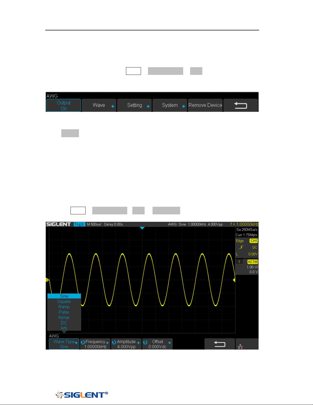
SDS1000X-E&SDS1000X-U User Manual
187
WWW.SIGLENT.COM
Output
Connect AWG with USB cable, and the oscilloscope interface indicates "AWG device
connection success", Press the Utility →Next Page4/4→ AWG, to enter the function
menu interface of the AWG system as shown below, including: Output, Wave,
Setting, System, and Remove Device.
Figure 115 AWG Menu Interface
Press Output softkey to open or close the AWG output .When the output is on, the
upper right corner of the oscilloscope interface will displays the corresponding
waveform frequency and amplitude information of AWG output wave.
Wave
To set standard waveform
Press the Utility→ Next Page4/4→AWG → Wave Type, Rotate the Universal Knob to
the Sine wave. Then press the knob to select the interface shown as below:
Figure 116 Wave Type Interface
The following table shows the waveform type and its corresponding characteristics.
SDS1000X-E&SDS1000X-U User Manual
188
WWW.SIGLENT.COM
According to the selected waveform, to set the waveform parameters through
Universal Knob and the corresponding function software under the menu.
Wave
Type
Parameters
Frequency
Range
Amplitude
(High-Z)
Offset
(High-Z)
Sine
Frequency/Period/Amplitude/Hi
gh-Level/Offset/Low-Level
value.
1uHz~25MHz
4mV~6V
± 3.0V
Square
Frequency/Period/Amplitude/Hi
gh-Level/Offset/Low-Level/Duty
value.
1uHz~10MHz
4mV~6V
± 3.0V
Ramp
Frequency/Period/Amplitude/Hi
gh-Level/Offset/Low-Level/Sym
metry value.
1uHz~300KH
z
4mV~6V
± 3.0V
pulse
Frequency/Period/Amplitude/Hi
gh-Level/Offset/Low-Level/
Width/ Width Fine value.
1uHz~10MHz
4mV~6V
± 3.0V
Noise
Stdev/ Mean value.
DC
Offset value.
± 3.0V
Arb
Frequency//Period/Amplitude/H
igh-Level/Offset/Low-Level
value
To set Arb waveform
Press the Utility→Next Page4/4→AWG→Wave Type, then select the Arb, and it has
two types:
Stored Arb
Users can edit the Arb through the PC which has installed the EasyWave software.
Send the edited Arb to the instrument through remote interface, and the Arb will be
stored in the instrument. Or read from the U disk which has stored the Arb. Choose
Wave Type→ Arb→ Arb Type→ Stored, enter the Stored Arb interface and invoke
the waveform in the internal storage and external storage device.
Built-in Arb
Choose Wave Type→ Arb →Arb Type→ Built-in to enter the following interface,
Rotate the knob to move the cursor, press the knob to select to the desired
waveform, and then return back to Built-in waveform interface.
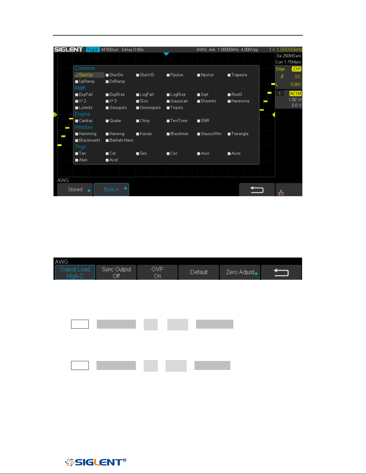
SDS1000X-E&SDS1000X-U User Manual
189
WWW.SIGLENT.COM
Figure 117 Built-in Arb Interface
Setting
Figure 118 AWG Setting Interface
Output Load
Press Utility→ NextPage4/4→ AWG → Setting→ Output Load to set High-Z or 50Ω.
Sync Output
Press Utility→ NextPage4/4→ AWG→ Setting→ Sync Output, the AWG provides Sync
output through the [Aux In/Out] connector on the rear panel. When the Sync Output
is on, the port can output a CMOS signal with the same frequency as basic
waveforms (except the Noise and DC), arbitrary waveforms, and modulated
waveforms (except external modulation).
OVP (Over Voltage Protection)
SDS1000X-E&SDS1000X-U User Manual
190
WWW.SIGLENT.COM
Press Utility→NextPage4/4→AWG→ Setting→ OVP to turn on or off the function. If
the state is set to ON, overvoltage protection of AWG output port take effect once
the condition is meeting (the absolute value of input voltage is higher than
4V±0.5V). When overvoltage protection occurs, a message will be displayed and
the output is disabled.
Default
Press Utility →NextPage4/4→ AWG→ Setting→ Default to recover the default
values of AWG (Sine, 1.000 KHz, 4.000Vpp, 0.0mVdc, High-Z, Sync output off, OVP
On).
Zero Adjust
Press Utility→ NextPage4/4→ AWG→ Setting→ Zero Adjust. The AWG can be
calibrated by using Auto mode or Manual mode. The adoption standard of AWG
calibrated is: when AWG outputs 0V DC signal, the corresponding channel at
1mv/div gear' mean value of oscilloscope is rang in ±1mv.
Auto mode: This mode can only be performed with the channel1 of
oscilloscope. Connect the output of AWG to the oscilloscope’channel1, press
the Auto soft key, then the AWG starts to automatic calibrate, and
displays ”Zero Adjust Success!”.
Manual mode: The AWG can be manually calibrated through any channel on
the oscilloscope.
Take channel 2 as an example:
a. Connect the output of AWG to the oscilloscope’ channel 2, open the
channel 2, and set DC coupling, open bandwidth limit, Probe is 1X.
b. Adjust the voltage of channel 2 channel to 1mv/div, and make the
waveform visible in the oscilloscope interface, press the
Measure and
measure the mean value of channel 2.
c. Press the Manual and rotate the knob to adjust the waveform, so that the
mean value of the observed CH2 will be in the range of ±1mv, and then
press the Save, the oscilloscope displays "Zero Adjust Success!".
Systems
System Status
Press Utility→NextPage4/4→AWG→System, then select the System Status option to
view the AWG’s system information, including software version, hardware version,
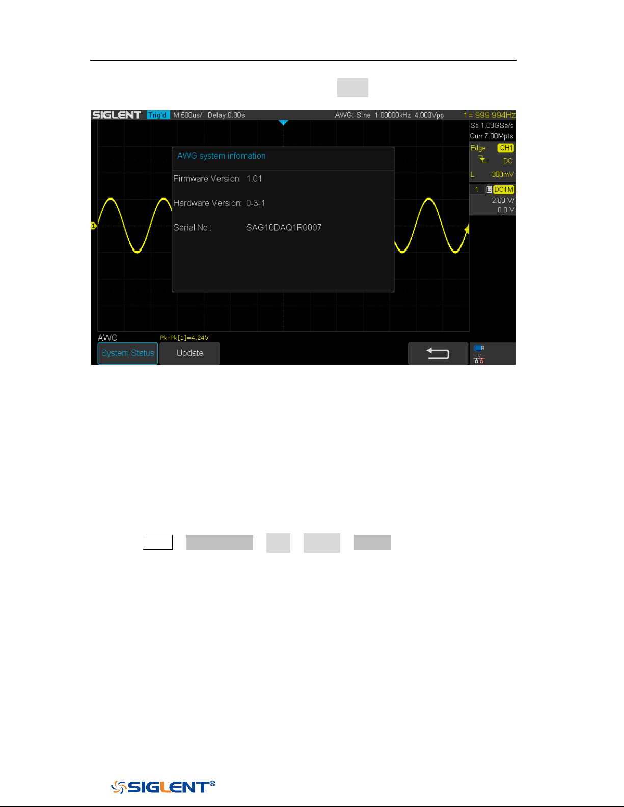
SDS1000X-E&SDS1000X-U User Manual
191
WWW.SIGLENT.COM
and serial number. After finished, press the return softkey to exit the system
information page.
Figure 119 AWG System Information Interface
Update
The software version file of the AWG can be updated directly via U-disk. Follow the
steps below:
1. Insert U-disk with firmware update file (*.ads) to USB host interface on the front
panel of the oscilloscope. Than a message “USB Flash Drive detected!” will
be displayed.
2. Press Utility →NextPage4/4→ AWG →System →Update.
3. Expand the U disk directory, Select the firmware file (*.ads), then press the
Press to update, an upgrade progress bar will be display on the interface.
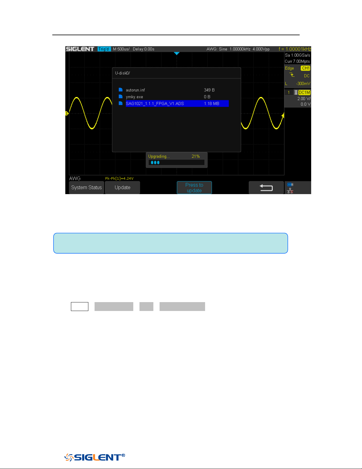
SDS1000X-E&SDS1000X-U User Manual
192
WWW.SIGLENT.COM
Figure 120 AWG Update Interface
4. After the updating is finished, the AWG will automatically disconnected and
display a message “
Update completed, please reconnect AWG device!”
Remove Device
Press Utility→NextPage4/4→AWG→Remove Device, and the oscilloscope interface
display "AWG device removed!", the device can be pulled.
Note:Don't cut off the power during the AWG is being updated!

SDS1000X-E&SDS1000X-U User Manual
193
WWW.SIGLENT.COM
IO Set
The oscilloscope provides abundant IO interfaces, including: USB Device and LAN.
USB Device
Do the following steps to set the oscilloscope to communicate with PC via USB:
1. Install the USBTMC device driver on PC. Suggest you install NI Vista.
2. Connect the oscilloscope with PC using a standard USB cable
3. Press the
Utility button on the front panel to enter the UTILITY function menu.
4. Press the IO Set softkey to enter the I/O SET function menu.
5. Press the USB Device softkey to view the USB ID.
6. Use EasyScopeX or NI Vista to communicate with the oscilloscope.
LAN
Do the following steps to set the oscilloscope to communicate with PC via LAN:
1. Connect the oscilloscope to your local area network using the network cable.
2. Press the
Utility button on the front panel to enter the UTILITY function menu.
3. Press the IO Set softkey to enter the I/O SET function menu.
4. Press the Net Interface softkey; then; select LAN.
5. Press the IP Set softkey to enter the IP setting interface, see the picture below:
6. Press the DHCP softkey to turn on or turn off the DHCP.
On: the DHCP server in the current network will assign the network
parameters (such as the IP address) for the oscilloscope.
Off: you can set the IP address, subnet mask, gate way manually.
Turn the Universal Knob to select the desired value.
Push the Universal Knob to change item horizontally.
Press the Save softkey to save the current setting.
7. Use EasyScopeX or NI Vista to communicate with the oscilloscope.
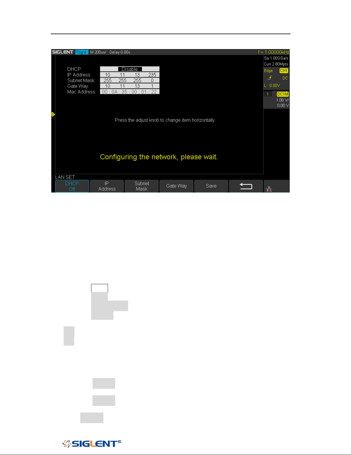
SDS1000X-E&SDS1000X-U User Manual
194
WWW.SIGLENT.COM
Figure 121 LAN Setting Interface
WLAN(Option)
SDS1000X-E (4-channel) supports this function. Do the following steps to set the
oscilloscope to communicate with PC via WLAN:
1. Connect the oscilloscope USB Host to your wireless network adapter, and make
sure your local wireless network is normal.
2. Press the
Utility button on the front panel to enter the UTILITY function menu.
3. Press the IO Set softkey to enter the I/O SET function menu.
4. Press the Net Interface softkey; then; select WLAN.
5. Press the WiFi Set softkey to enter the Wi-Fi set interface.
6. Press the Wi-Fi Operation softkey to turn on or turn off the WIFI set menu.
Off: the WIFI set menu off
On: you can set the SSID and PSK manually.
Manual Scan: press this softkey, the oscilloscope will search the network
automatically. Turn the
Universal Knob to select a network; then; press
Universal Knob to confirm.
SSID: press this softkey, a dialogue box will pop up, enter your SSID then
press Confirm.
PSK: press this softkey, a dialogue box will pop up, enter your SSID then
press Confirm.
Connect: press this softkey to connect the wireless network.
7. Press Connect softkey when your SSID and PSK configuration finished.
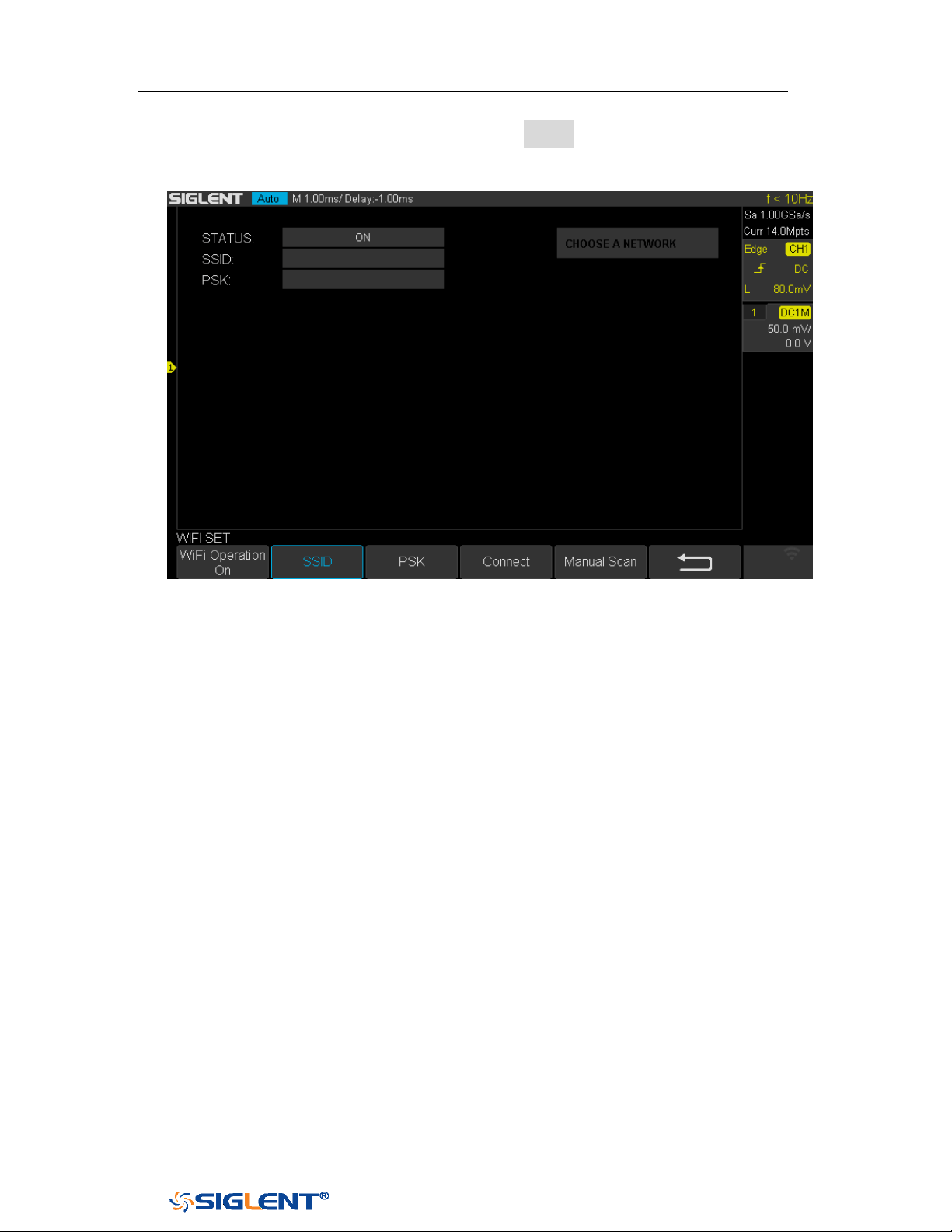
SDS1000X-E&SDS1000X-U User Manual
195
WWW.SIGLENT.COM
8. Return to the I/O SET menu. Press the IP Set softkey to finish the IP
configuration(see “To Set the LAN”)
9. Use EasyScopeX or NI Vista to communicate with the oscilloscope.
Figure 122 WIFI Setting Menu
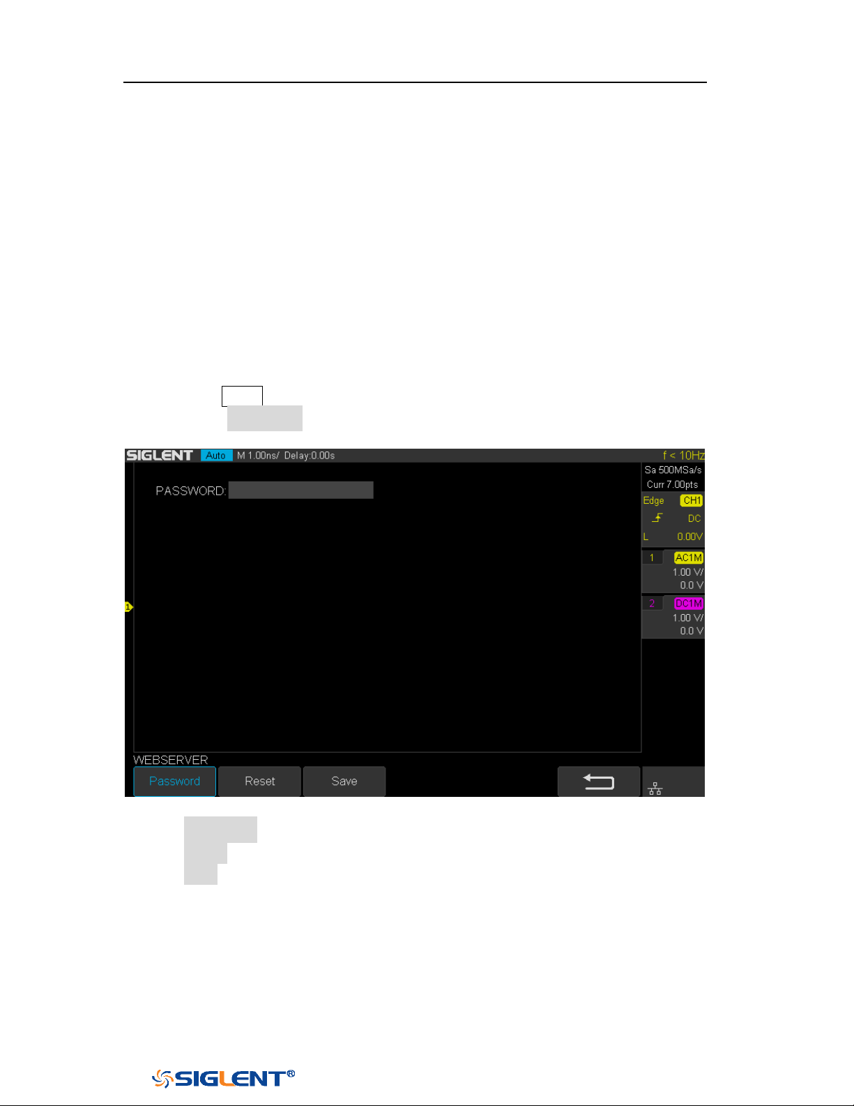
SDS1000X-E&SDS1000X-U User Manual
196
WWW.SIGLENT.COM
Web Server
SDS1000X-E (4-channel) provide the web server function; you can access and
control the oscilloscope using a web browser. Connect the oscilloscope to your LAN
(or WLAN), then type the oscilloscope's IP address in the web browser. The
oscilloscope's web interface is displayed.
Set Password
1. Press the
Utility button on the front panel to enter the UTILITY function menu.
2. Press the WebServer softkey on the fourth page of utility function menu to
enter the WEBSERVER menu.
Figure 123 Web Server Interface
Password: press this softkey to set a new password,
Reset: press this softkey to reset the password.
Save: After setting a new password, press this softkey to make the
password effective.
Web Browser
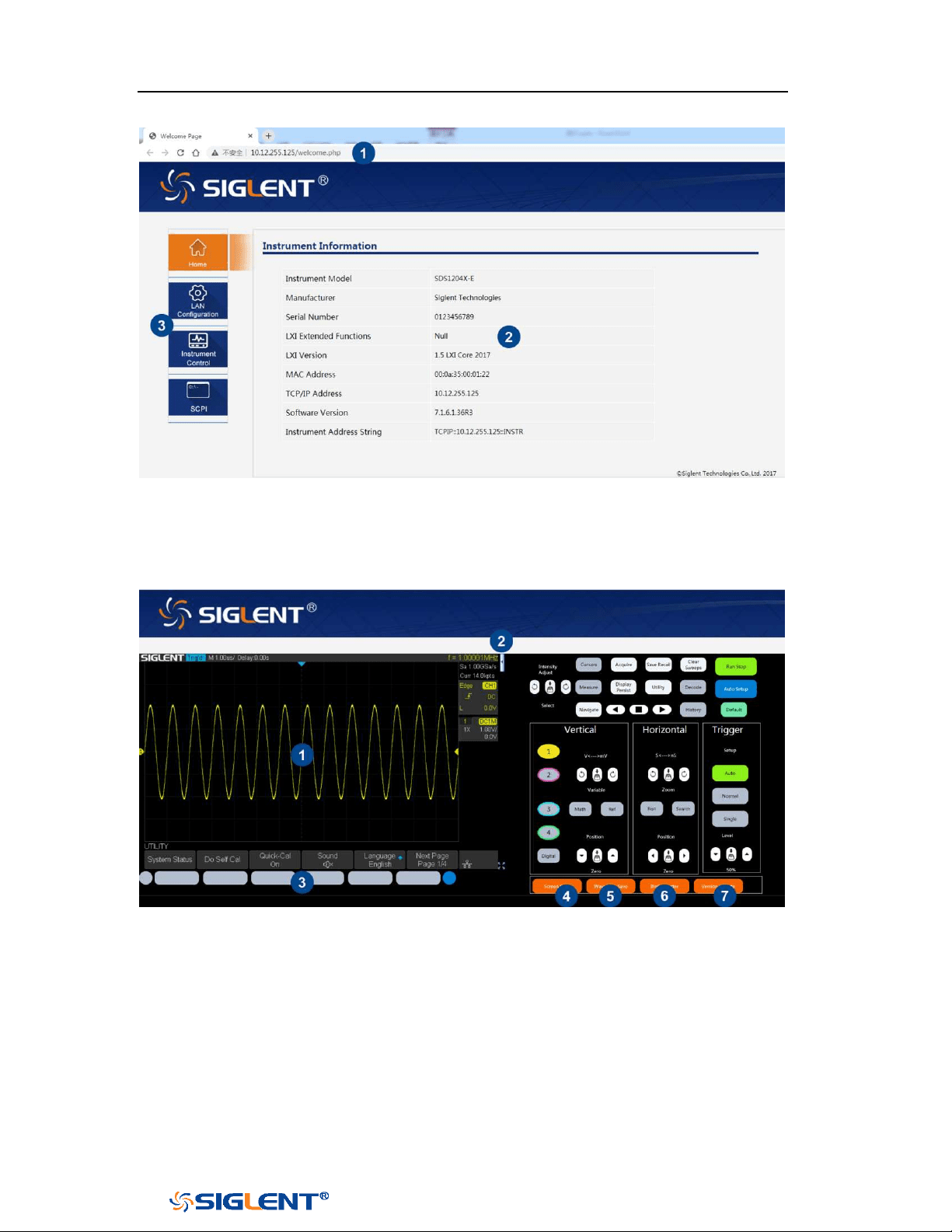
SDS1000X-E&SDS1000X-U User Manual
197
WWW.SIGLENT.COM
1 Input the IP address of the instrument
2 Information of the instrument
3 Click here to enter the instrument control interface.
1 Display area of the instrument. The display in this area is a copy from the
instrument display.
2 Click here to show the instrument control area.
3 Control area of the instrument. Using the mouse to operate in the area is
equivalent to directly operating the instrument through the buttons
4 Click here to perform a screen shot
5 Click here to save the waveform data as a bin file and download it to the local
computer
6 Click here to download the mini tool for converting bin file to csv file

SDS1000X-E&SDS1000X-U User Manual
198
WWW.SIGLENT.COM
7 Click here to perform a firmware upgrade
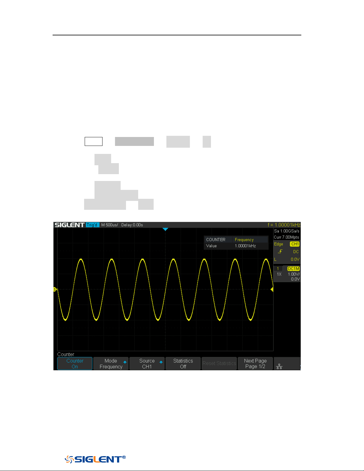
SDS1000X-E&SDS1000X-U User Manual
199
WWW.SIGLENT.COM
Counter
SDS1000X-E (4-channel) supports counter function, which is used to measure the
frequency and period of a signal or count the events happening within it. The
counter is asynchronous to the acquisition system of the oscilloscope. It can work
well even if the acquisition of the oscilloscope is stopped (indicated by a red
colored Run/Stop button)
1 Press Utility → NextPage2/4 → Counter → On to turn on Counter function
menu.
2 Press the Mode softkey to select Frequency, Period and Totailzer.
3 Press the Source softkey to select the source of the counter. The analog
channel can be used as the source.
4 Press the Statistics softkey to turn on or off statistics.
5 Press the Reset Statistics softkey to clear and restart the statistics.
6 Press Next Page1/2 → Level, turn the Universal Knob to set the level of the
counter.
Figure 124 Counter Setting Interface
When the mode is selected as totalizer, the edge of the counting source needs to
be set. When the counting gate is turned on, the counter can count only when the
gate source meets the specified conditions.
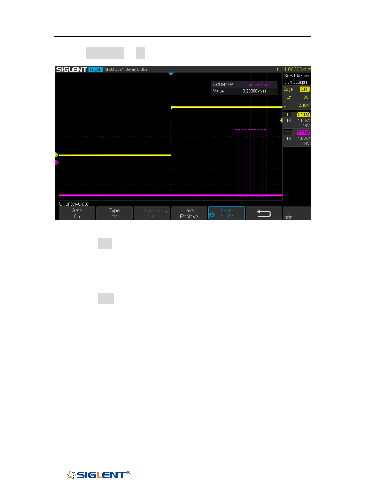
SDS1000X-E&SDS1000X-U User Manual
200
WWW.SIGLENT.COM
1 Press Gate Setting → On to enter the Counter-Gate function menu.
Figure 125 Counter-Gate Setting Interface
2 Press the Type softkey to select the gate type, Level or After Edge.
3 Gate source display area. C1 and C2 are gate sources of each other, C3 and C4
are gate sources of each other.
4 When the gate type is level, set the polarity (Positive or Negative) of the gate
source. When the gate type is edge, set the slope (
Rising or Falling edge) of the
gate source.
5 Press the Level softkey and turn the Universal Knob to set the gate level.
When statistics are enabled, the counter will increment the data and display the
statistics results on the screen.
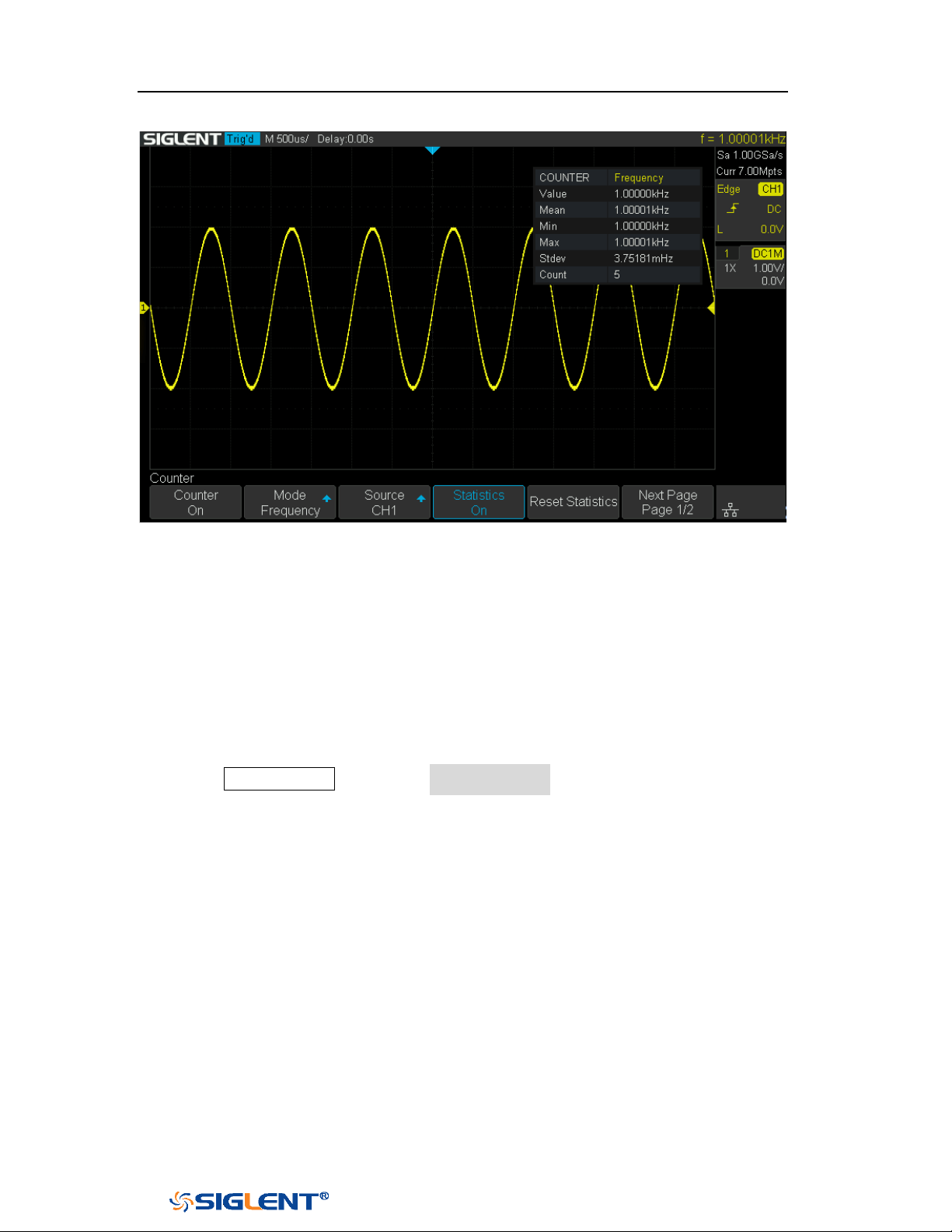
SDS1000X-E&SDS1000X-U User Manual
201
WWW.SIGLENT.COM
Figure 126 Statistics Function
Value: The latest count
Mean: The average of all historical counts
Min: The minimum of all historical counts
Max: The maximum of all historical counts
Stdev: The standard deviation of all historical counts, used to judge the
distribution of historical count parameters
Count: Number of counts obtained
Press the Clear Sweeps button or Reset Statistics softkey to clear and restart
statistics.
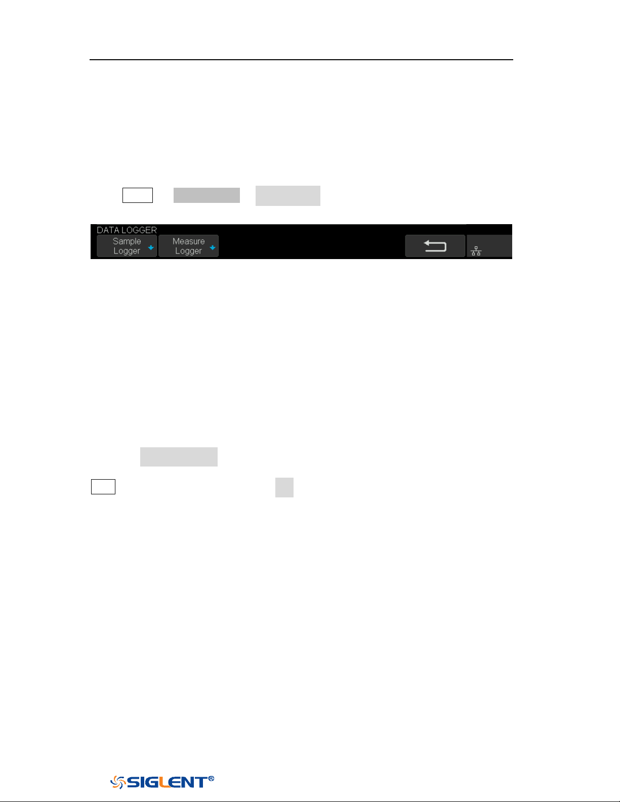
SDS1000X-E&SDS1000X-U User Manual
202
WWW.SIGLENT.COM
Data Logger
SDS1000X-E (4-channel) supports Sample logger and Measure logger, which can
record waveform data and measurement value.
Press Utility → NextPage2/4 →Data Logger to enter the DATA LOGGER function
menu.
Figure 127 Data Logger Interface
Sample Logger
The Sample logger can record the original points of waveform in real time at equal
intervals to realize the long-time observation of low-speed signals. The recorded
data can be stored in the internal or external storage device in real time. After
stopping recording, users can replay the waveform on the oscilloscope, also can
export the recorded data and then analyze on the PC.
Press the Sample Logger softkey to enter the sample logger interface. At this time,
all the buttons on the front panel will not respond (except for the menu softkey,
Print and Universal Knob). Press the Exit softkey to exit the sample logger.
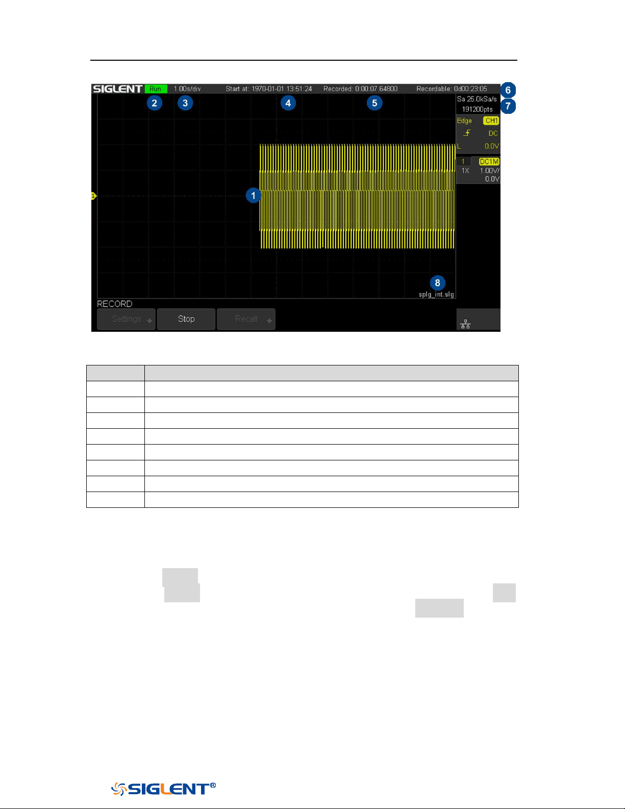
SDS1000X-E&SDS1000X-U User Manual
203
WWW.SIGLENT.COM
Figure 128 Sample Logger Interface
No.
Description
1
Recorded waveform
2
Record status(Run/Stop)
3
Horizontal scale
4
Start time
5
Recorded time
6
Remaining recordable time
7
Sample rate and recorded points of waveform
8
Storage location
Record Waveform
1 Press the Record softkey to enter the RECORD function menu.
2 Press the Setting softkey to enter the SETTINGS function menu. Press the Rate
softkey to set the sampling rate of the waveform. Press the Record to softkey to
set the storage location of the recorded data:
Internal: Record the data to internal, the last recorded internal data will be
overwritten. Please confirm the operation when start to record.
External: Record the data to external storage device, and set the external
storage path.
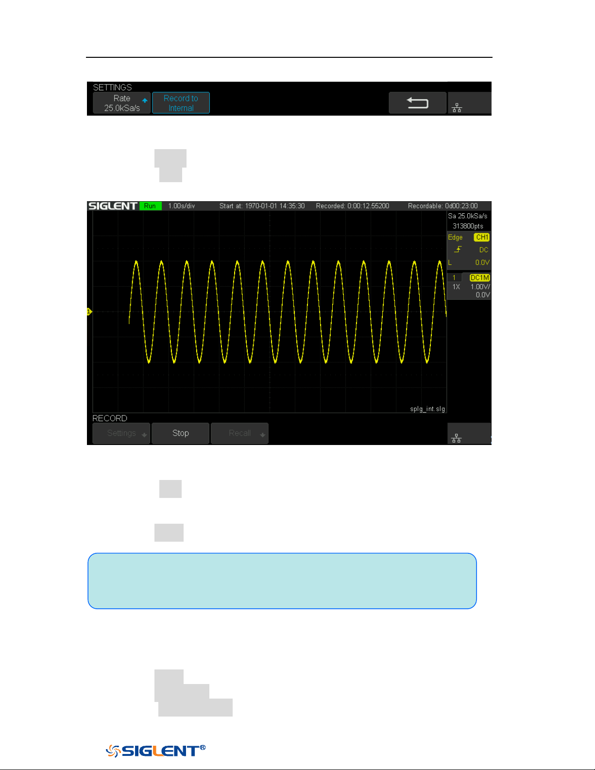
SDS1000X-E&SDS1000X-U User Manual
204
WWW.SIGLENT.COM
Figure 129 Settings Interface
3 Press the Return softkey to return to the RECORD function menu.
4 Press the Start softkey to start to record, and the record status in the top
information bar is displayed as "Run".
Figure 130 Start Recording Waveform
5 Press the Stop softkey to stop recording, and the record status in the top
information bar is displayed as "Stop", the data is automatically stored in the
storage location.
6 Press the Recall softkey to look back and analyze the waveform.
Recall Recorded Waveform
1 Press the Recall softkey to enter the RECALL function menu.
2 Press the Recall from softkey to select the storage path.
3 Press the Press to Recall softkey to recall the recorded waveform data and
Note: When recording to external, the waveform data will be stored to the
external in real time. Please do not pull out the U disk during the recording
process!
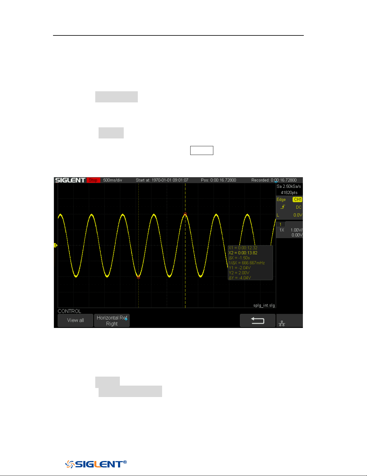
SDS1000X-E&SDS1000X-U User Manual
205
WWW.SIGLENT.COM
enter the CONTROL menu automatically.
Display Control
1 Press the Horizontal Ref softkey to set the horizontal reference position.
2 Rotate the Horizontal Scale knob to zoom the waveform with the horizontal
reference as the center. Rotate the Horizontal Position knob to move the
waveform.
3 Press the View all softkey to return to the initial configuration to view all
waveforms.
4 After recalling the waveform, press the Cursors button to turn on the cursor
function, which can measure and analyze the waveform on the screen. Please
refer to the chapter "Cursors" for operation.
Figure 131 View Recorded Waveform
Manage Internal Record
1 Press the Manage softkey to enter the MANAGE function menu.
2 Press the Export Internal Data softkey to export the internal record to the
external storage device. See the chapter "Save and Recall" for operation. The
file format (*.slg) is described in detail in the document "How to Extract Data
from the Binary File.docx". Please download from SIGLENT website. The
oscilloscope provides a tool named fileconverter to convert the waveform file
(*.slg) to CSV format. You can download it from the Save/Recall menu or the

SDS1000X-E&SDS1000X-U User Manual
206
WWW.SIGLENT.COM
webserver.
3 Press the Delete Internal Data softkey to delete the internal record.
SDS1000X-E&SDS1000X-U User Manual
207
WWW.SIGLENT.COM
Measure Logger
The Measure logger can record the measured value of waveform in real time to
realize the long-time measurement trend observation of low-speed signal. The
measurement data is recorded in the internal, and can be stored to the internal or
external storage device after stopping recording. It can support up to 4 traces of
data at the same time.
Turn on the measure function and add measurement items, then press Utility →
NextPage2/4 → Data Logger → Measured Logger to turn on the measure logger;
Press the Exit softkey to exit the measure logger.
Figure 132 Measure Logger Interface
No.
Description
1
Record trace
2
Record status(Run/Stop)
3
[Auto/Manual] Horizontal scale
4
[Auto/Manual] Time value of the first point (centered on horizontal
reference position)
5
Horizontal reference position
6
Recording interval
7
Start time
8
Number of recorded points, Recorded time, Used memory
9
Remaining recordable time
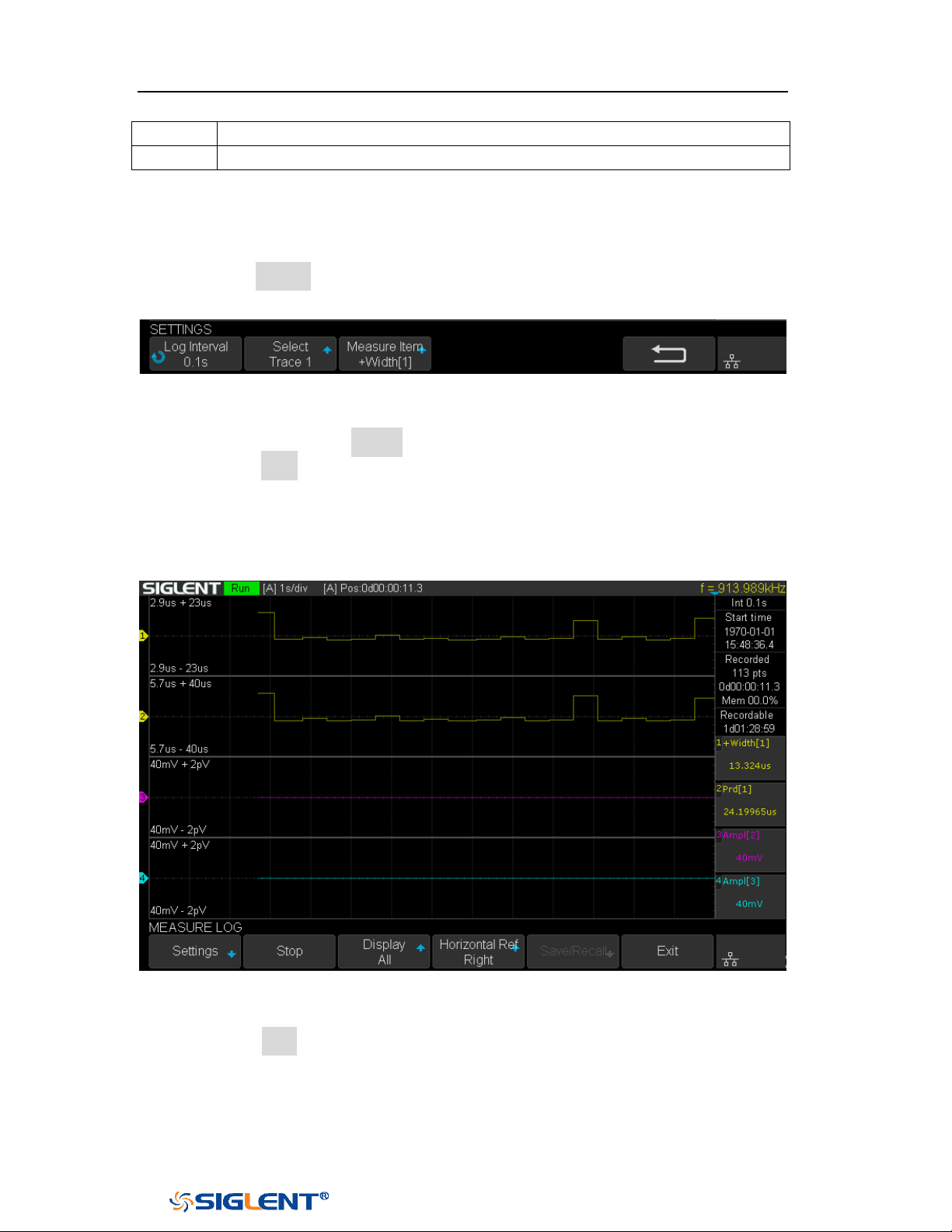
SDS1000X-E&SDS1000X-U User Manual
208
WWW.SIGLENT.COM
10
The current value of measurement items
11
Upper and lower scale of measurement items
Start/Stop Recording
1 Press the Setting softkey to enter the SETTINGS function menu. Set record
interval, record trace and the corresponding measurement item.
Figure 133 Settings Interface
2 After setting, press the Return softkey to return to the previous menu.
3 Press the Start softkey to start to record, the record status in the top
information bar is displayed as "Run". During the recording process, the
measure logger automatically adjusts the horizontal scale to show the trace.
Users also can turn the horizontal scale/position knob to enter the manual
mode to zoom and move the recording trace.
Figure 134 Start to Record Measurement Data
4 Press the Stop softkey to stop recording, the record status in the top
information bar is displayed as "Stop".
Display Control
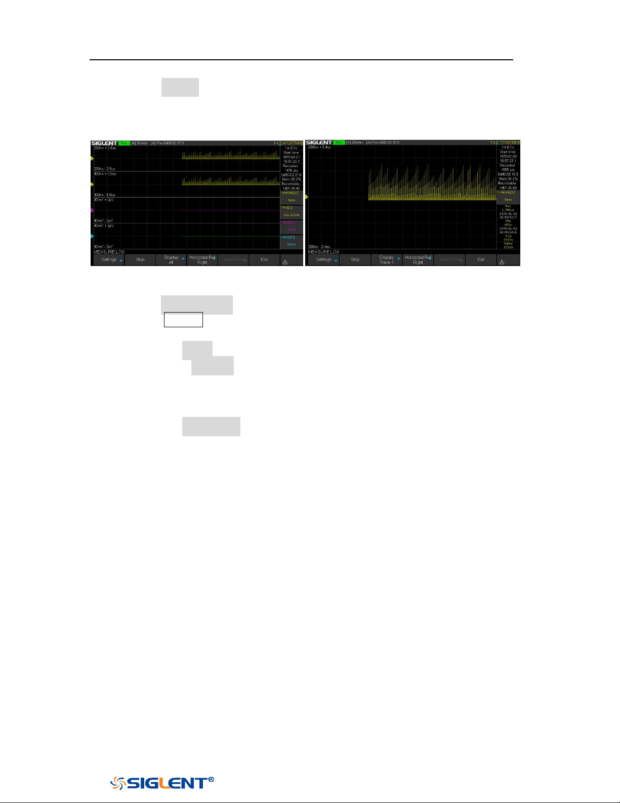
SDS1000X-E&SDS1000X-U User Manual
209
WWW.SIGLENT.COM
1 Press the Display softkey to select All, all traces are displayed in the waveform
area. When a trace is selected, only the selected trace is displayed in the
waveform area. Press the channel button corresponding to the trace to switch
all/individual display.
All Traces Display
Single Trace Display
2 Press the Horizontal Ref softkey to set the horizontal reference position.
3 Press the Cursors button to turn on the cursors function. Move the cursor to
obtain the measured value of each point.
a. Press the Select softkey to select the cursor T1, T2 or T1-T2.
b. Press the Strategy softkey to choose the behavior of cursors when
horizontal scale or position is changed.
Fixed Position: cursors remain fixed to the grid position on the display
Fixed Time: the value of cursors remain fixed.
c. Press the Track Mode softkey to select the track mode of T-Cursors.
Normal: Track the data at the time of T-Cursors
Maximum: Track the maximum value of the data within a pixel where
T-Cursors are located.
Average: Track the average value of the data within a pixel where
T-Cursors are located.
Minimum: Track the minimum value of the data within a pixel where
T-Cursors are located.
Peak: Track the data with the maximum deviation from the overall
average value in a pixel where T-Cursors are located. When two
cursors are at the same position, T1 will track the maximum value and
T2 will track the minimum value.
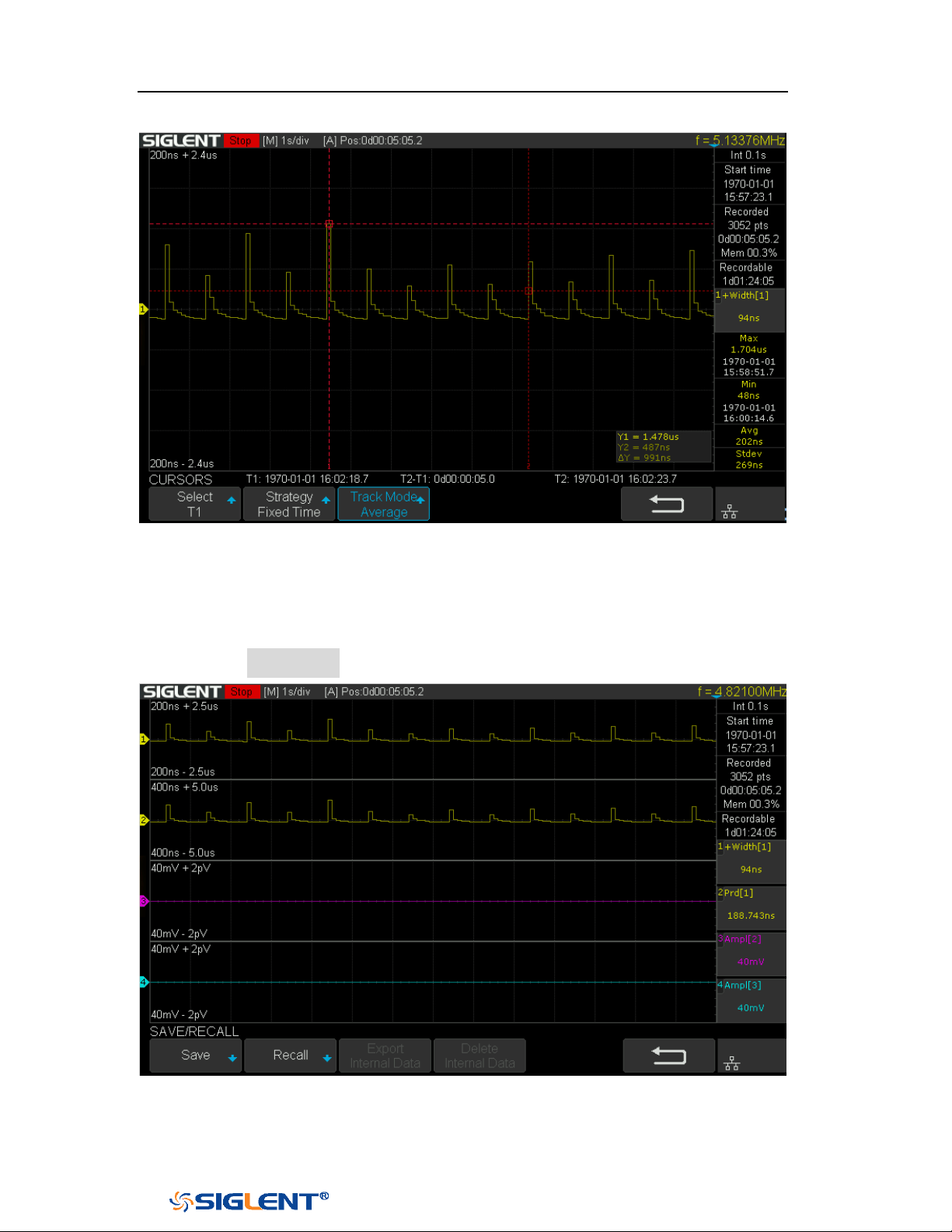
SDS1000X-E&SDS1000X-U User Manual
210
WWW.SIGLENT.COM
Figure 135 Cursors of Measure Logger
Storage Measurement Record
1 Press the Save/Recall softkey to enter the SAVE/RECALL function menu.
Figure 136 Save/Recall of Measure Logger
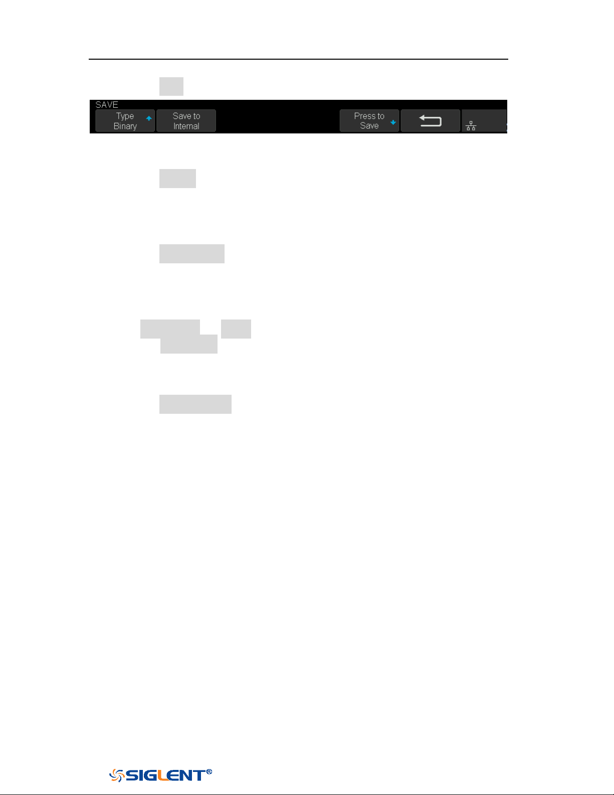
SDS1000X-E&SDS1000X-U User Manual
211
WWW.SIGLENT.COM
2 Press the Save softkey to enter the SAVE menu.
Figure 137 Save of Measure Logger
3 Press the Save to softkey to select where to store.
Internal: The measurement data will be saved in binary data format, and
the last data stored internally will be overwritten.
External: The measurement data can be saved as binary data(*.mlg), CSV
data or MATLAB data
4 Press the Press to save softkey to save.
Recall Measurement Record
1 Press Save/Recall → Recall to enter the RECALL function menu.
2 Press the Recall from softkey to select where to recall. Only binary files can be
recalled from internal; while binary files or MATLAB files can be recalled from
external. If the current data is not saved, it will be covered by the recalled the
data.
3 Press the Press to Recall softkey to recall.
Manage Internal Record
Export or delete the internal record, it is similar to "Manage Internal Record" of
Sample Logger.
SDS1000X-E&SDS1000X-U User Manual
212
WWW.SIGLENT.COM
Update Firmware and Configuration
The firmware and configuration can be updated directly via USB flash driver.
Do the following steps to update the firmware:
1. Insert the USB flash driver which with the firmware and the configure files
inside into the USB host interface on the front panel of the oscilloscope.
2. Press the
Utility button on the front panel to enter the UTILITY function menu.
3. Press the Next Page softkey to go to the third page of the UTILITY function
menu.
4. Press the Update softkey to enter the UPDATE function menu.
5. Press the Firmware softkey to open the file manager.
6. Turn the Universal Knob to select the update file which should be with an ADS
postfix; and then press the Press to Update softkey to start update the
firmware. The process needs about 7 minutes. And during the update, do not
remove power to the oscilloscope, otherwise the oscilloscope may be
permanently damaged and may not restart again.
7. After finish the update, the screen will pop-out the message “Firmware
decompressed. Please restart and wait…”.
8. Restart the oscilloscope to finish the firmware update.
Do the following steps to update the configuration:
1. Insert the USB flash driver which with the firmware and the configure files
inside into the USB host interface on the front panel of the oscilloscope.
2. Press the
Utility button on the front panel to enter the UTILITY function menu.
3. Press the Next Page softkey to go to the third page of the UTILITY function
menu.
4. Press the Update softkey to enter the UPDATE function menu.
5. Press the Configure softkey to open the file manager.
6. Turn the Universal Knob to select the update file (*.CFG file extension) and then
press the Press to Update softkey to start update the firmware. The process
needs about 30 seconds.
7. After finish the update, the screen will pop-out the message “Firmware
decompressed. Please restart and wait…”
8. Restart the oscilloscope to finish the configuration update.
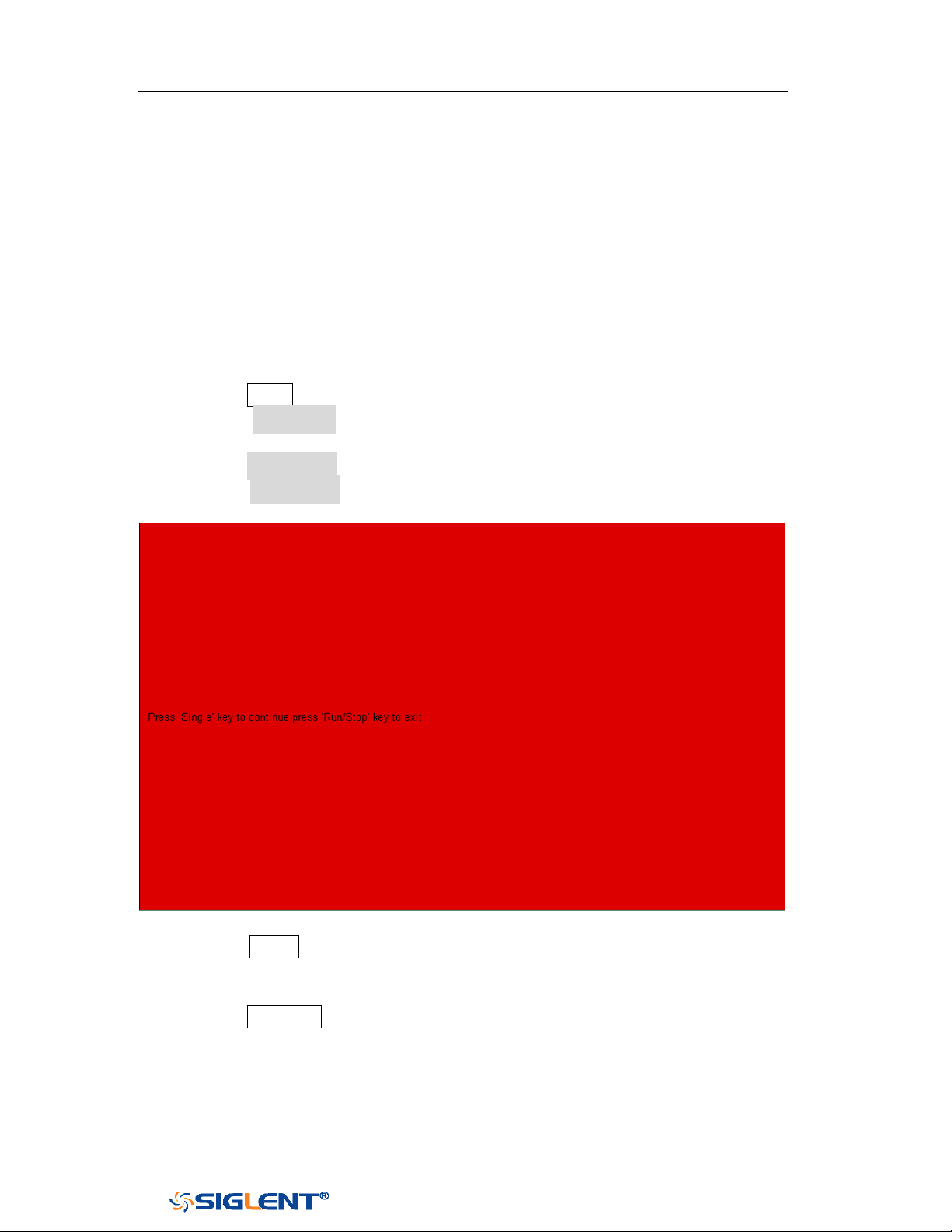
SDS1000X-E&SDS1000X-U User Manual
213
WWW.SIGLENT.COM
Do Self-Test
Self-tests include screen test, keyboard test, and LED test. Self-tests used to test the
screen, buttons, knobs and LED lights whether works well.
Screen Test
1. Press the Utility button on the front panel to enter the UTILITY function menu.
2. Press the Next Page softkey to go to the third page of the UTILITY function
menu.
3. Press the Do Self Test softkey to enter the SELFTEST function menu.
4. Press the Screen Test softkey to enter the screen test interface, as the picture
shown below, the screen display pure red.
Figure 138 Screen Test
5. Press the
Single button on the front panel continually as it says in the picture
above. The screen displays green, blue and red again. It is easy to check
chromatic aberration, stain and scratch of the screen under the condition.
6. Press the Run/Stop button on the front panel to exit the screen test program.
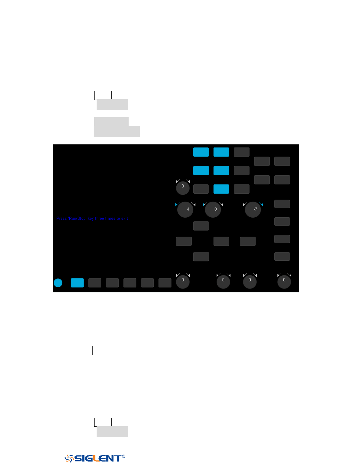
SDS1000X-E&SDS1000X-U User Manual
214
WWW.SIGLENT.COM
Keyboard Test
Keyboard test is used to test that if the keys or the knobs work well.
Do the following steps to do keyboard test:
1. Press the Utility button on the front panel to enter the UTILITY function menu.
2. Press the Next Page softkey to go to the third page of the UTILITY function
menu.
3. Press the Do Self Test softkey to enter the SELFTEST function menu.
4. Press the Keyboard Test softkey to enter the keyboard test interface, as the
picture shown below.
Figure 139 Keyboard Test
5. To perform the knobs and the buttons test.
6. Knobs test: the default value is 0. Turn left to increase the value while turn right
to decrease; push the knob to set the value to 0. Test every knob randomly.
7. Keys test: the first time to press the key to light it up, and a second press to die
out. Test every button randomly.
8. Press the
Run/Stop button 3 times to exit the keyboard test program.
LED Test
LED test is used to test that if the button lights work well.
1. Press the Utility button on the front panel to enter the UTILITY function menu.
2. Press the Next Page softkey to go to the third page of the UTILITY function
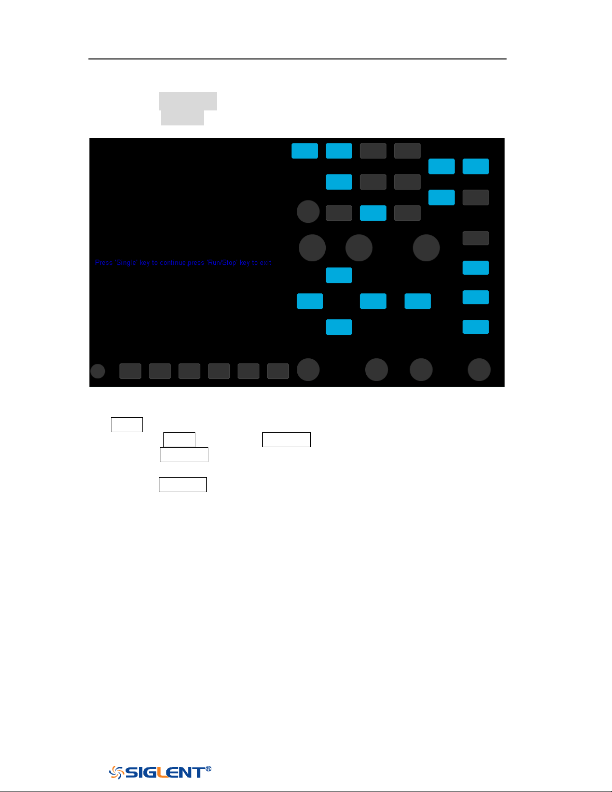
SDS1000X-E&SDS1000X-U User Manual
215
WWW.SIGLENT.COM
menu.
3. Press the Do Self Test softkey to enter the SELFTEST function menu.
4. Press the LED Test softkey to enter the keyboard test interface, as the picture
shown below.
Figure 140 LED Test
5. According to the prompting information displaying on the screen, press the
Single button continually to light the button lights one by one. The first time to
press the Single button, the Run/Stop button displays red, and the second
press the Run/Stop button displays green. Then the other button lights will be
lighted one by one. At last all the lights will be lighted at the same time.
6. Press the Run/Stop button to exit the LED test program.

SDS1000X-E&SDS1000X-U User Manual
216
WWW.SIGLENT.COM
Screen Saver
When the oscilloscope enters the idle state and holds for a certain period of time,
the screen saver program will be enabled.
Do the following steps to set the screen saver time:
1. Press the
Utility button on the front panel to enter the UTILITY function menu.
2. Press the Next Page softkey to go to the third page of the UTILITY function
menu.
3. Press the Screen Saver softkey; and then turn the Universal Knob to select the
desired screen saver time. The screen saver time can be set to 1min, 5min,
10min, 30min, and 1hour. Also you can select Off to turn off the screen saver
function
Figure 141 Screen Saver Interface
4. Press the any button on the front to exit the screen saver program.

SDS1000X-E&SDS1000X-U User Manual
217
WWW.SIGLENT.COM
Date/Time
SDS1000X-E (4-channel) supports setting date and time. After restarting the
oscilloscope, you need to reset the system time.
1 Press Utility → NextPage3/4 → Date/Time to enter the DATA/TIME function
menu.
2 Press the Display softkey to select On to display the date and time.
Figure 142 Date/Time Function Interface
Set Date/Time
Press the Date/Time softkey to enter the Data/Time setting menu. Press the Date
softkey and press the Universal Knob to select year, month or day, then rotate the
Universal Knob to change value. Modifying the time is similar to the date.
Figure 143 Setting Date/Time

SDS1000X-E&SDS1000X-U User Manual
218
WWW.SIGLENT.COM
Set Time Zone
1 Press the Time Zone softkey to enter the Time Zone function menu, and pop up
time zone page.
2 Rotate the Universal Knob to select the time zone.
3 Press the Confirm softkey to confirm the selection.
Figure 144 Time Zone Setting Interface
Set NTP
1 Press the NTP softkey to enter the NTP function menu,
2 Press the Server IP softkey to set the server IP address according to the prompt
and press the Sync softkey to synchronize the time.
3 Press the Power On Sync softkey to select On or Off. When set to On, the
oscilloscope will automatically synchronize the time after the power on.
4 Press the Periodic Sync softkey to select On; press the Interval softkey and
rotate Universal Knob to set the value.
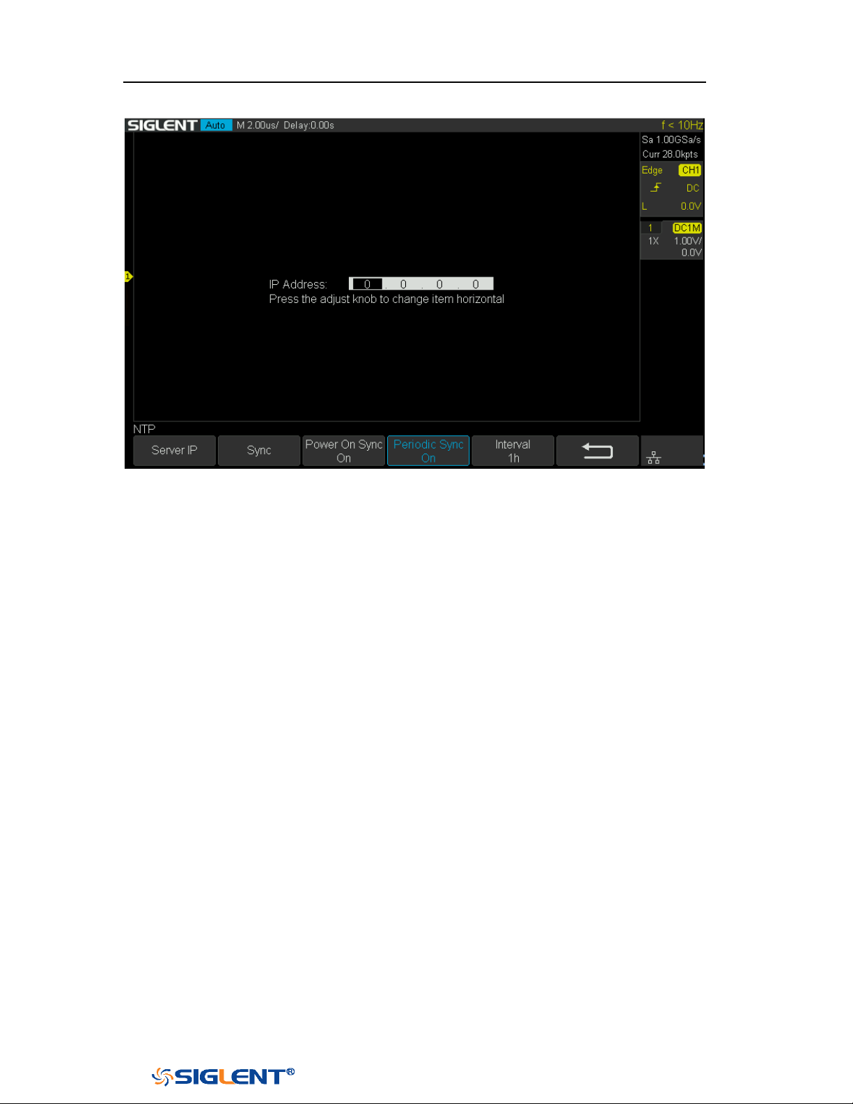
SDS1000X-E&SDS1000X-U User Manual
219
WWW.SIGLENT.COM
Figure 145 NTP Setting Interface

SDS1000X-E&SDS1000X-U User Manual
220
WWW.SIGLENT.COM
Reference Position
The reference position setting determines the physical point that the oscilloscope
uses during vertical and horizontal scale changes. In some situations, it is more
convenient to use a fixed position on the display.
Press the Utility button on the front panel and then press the Reference Pos. softkey
to enter the Reference POS menu.
Press the Vertical softkey to select Fixed Offset or Fixed Position.
Fixed Position: when the vertical gain is changed, the oscilloscope will keep the
vertical offset level indicator stationary.
Fixed offset: when the vertical gain is changed, the oscilloscope will have the
vertical offset level indicator move with the actual voltage level.
Press the Horizontal softkey to select Fixed Delay or Fixed Position.
Fixed Position: when the timebase is changed, the oscilloscope will keep the
horizontal offset indicator stationary.
Fixed Delay: when the timebase is changed, the oscilloscope will have the
horizontal offset indicator move with the trigger point.
Power On Line
Press the Utility button on the front panel; then; press Power On Line softkey to
select Enable or Disable.
Enable: when the oscilloscope is energized, the oscilloscope will start
automatically by itself.
Disable: when the oscilloscope is energized; then; press the power key at the
lower-left corner of the front panel to start the oscilloscope.
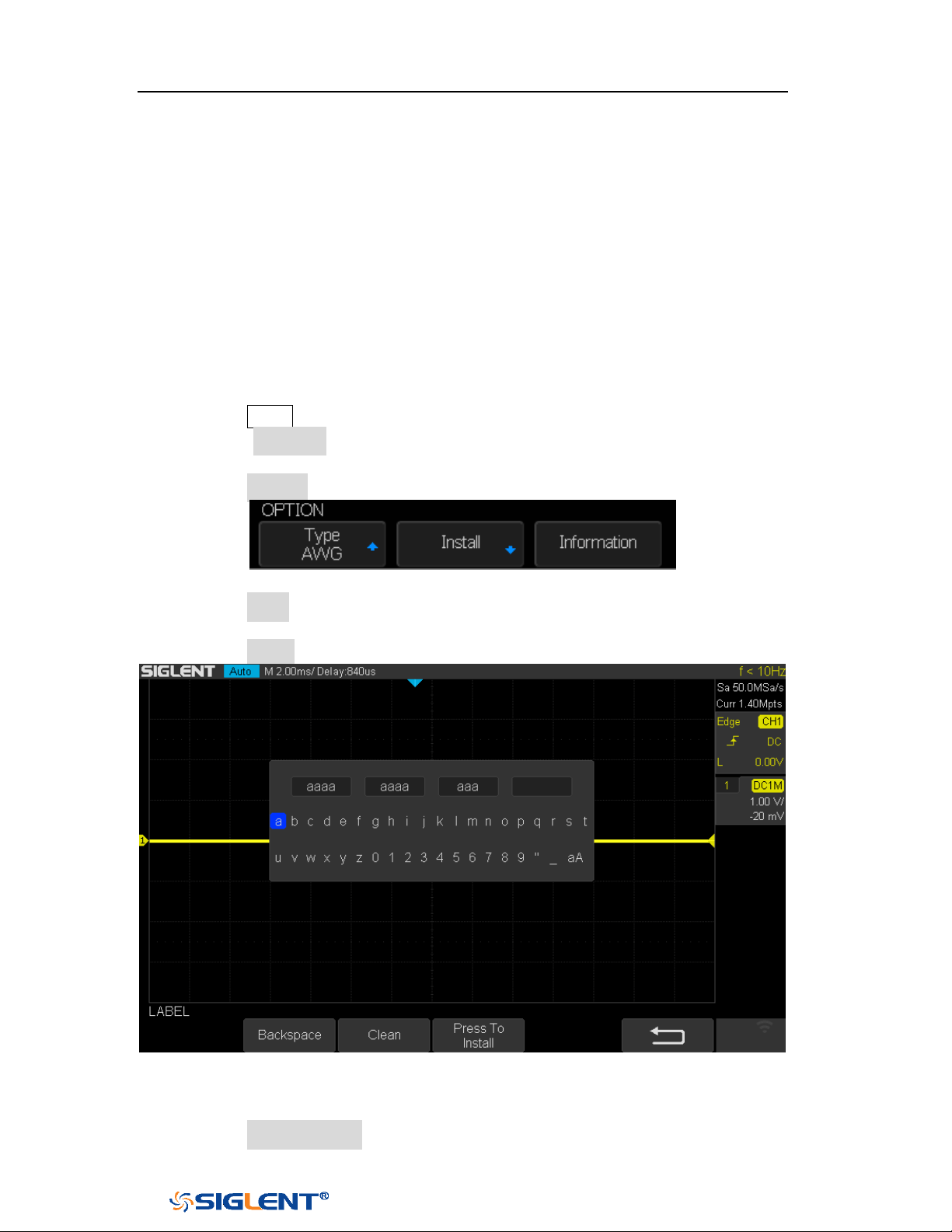
SDS1000X-E&SDS1000X-U User Manual
221
WWW.SIGLENT.COM
Option Management
The SDS1000X-E and SDS1000X-U provide multiple options to fulfill your
measurement requirements. Please contact your
SIGLENT sales representative or
SIGLENT technical support to order the corresponding options. You can view the
options currently installed on the oscilloscope or activate the newly purchased
option license codes through this menu.
Do the following steps to install the option on the oscilloscope:
1. Press the
Utility button on the front panel to enter the UTILITY function menu.
2. Press the Next Page softkey to go to the third page of the UTILITY function
menu.
3. Press the Options softkey to enter the OPTION function menu.
Figure 146 OPTION Function Menu
4. Press the Type softkey; then turn the Universal Knob to select the module to be
installed and push down the knob to confirm.
5. Press the Install softkey to enter the LABEL function menu to input the license.
Figure 147 LABEL Function Menu
Turn the
Universal Knob to select character
Push down the Universal Knob to confirm the characters
Press the Press To Install when license key input done,
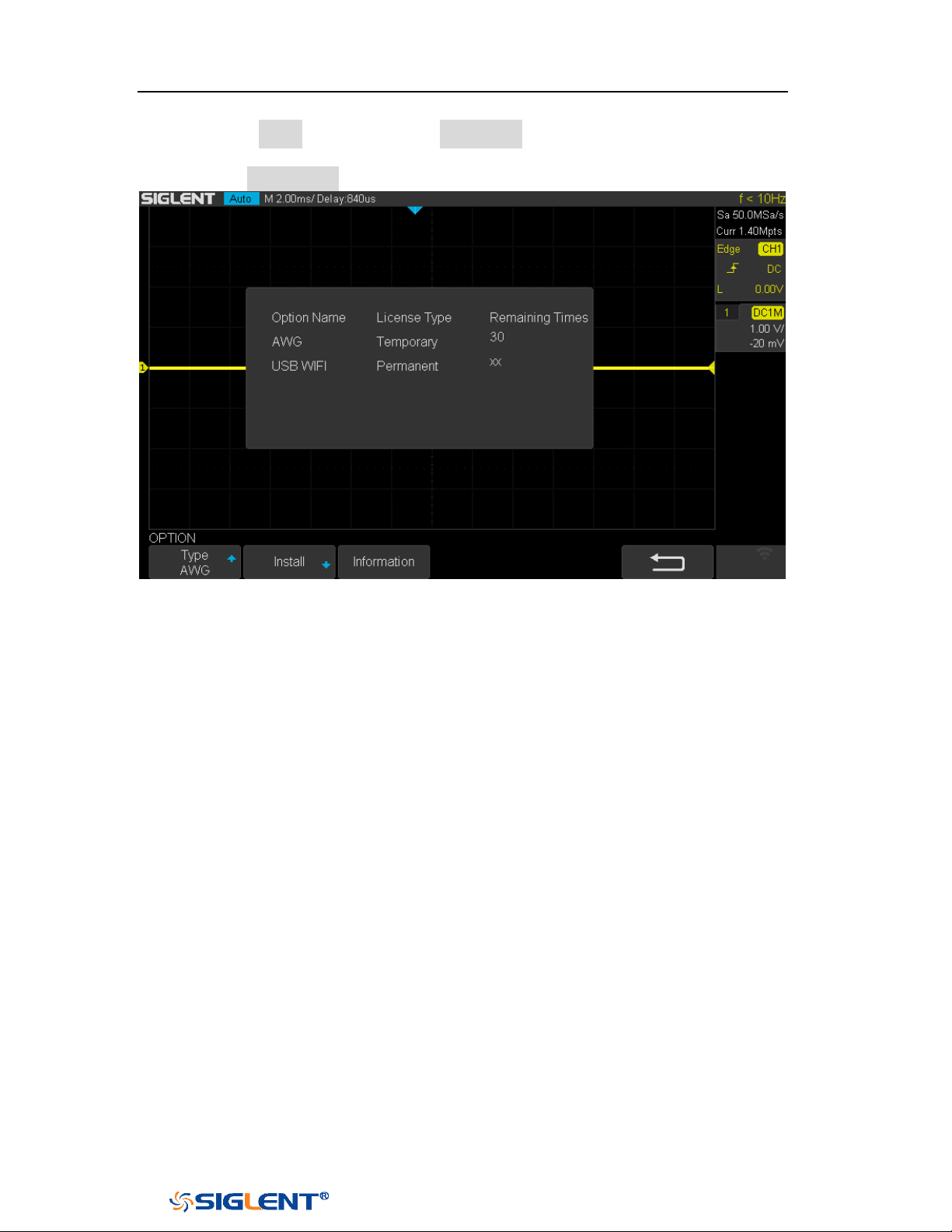
SDS1000X-E&SDS1000X-U User Manual
222
WWW.SIGLENT.COM
Press the Clean softkey or the Backspace softkey to delete the incorrect
character.
6. Press the Information softkey to view the option information.
Figure 148 Option Information
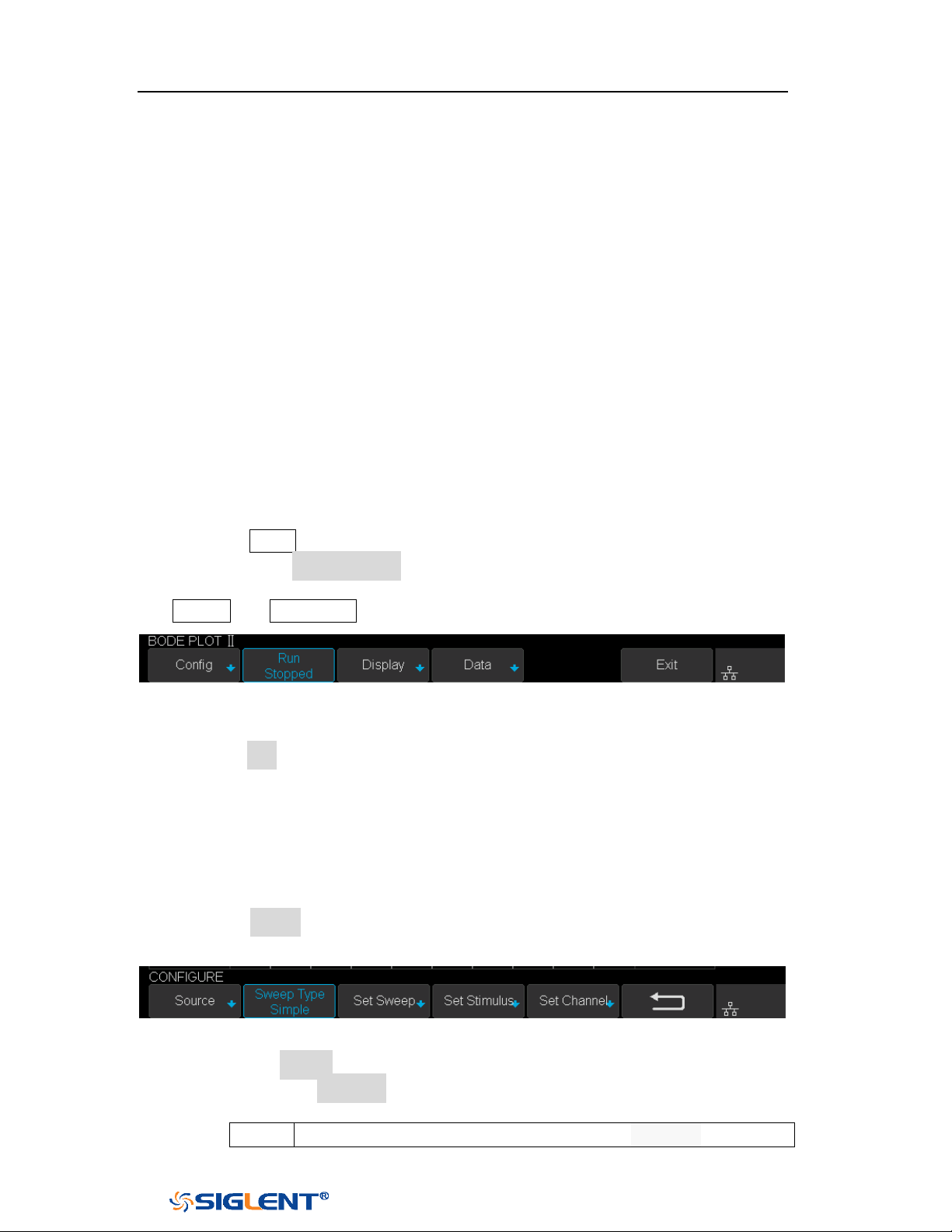
SDS1000X-E&SDS1000X-U User Manual
223
WWW.SIGLENT.COM
Bode Plot II
The bode plot application for the SDS1000X-E (4-channel) control an external
arbitrary waveform generator(only Siglent’s arbitrary waveform generator can be
supported) to sweep a sine wave across a range of frequencies while measuring
the input to and output from a device under test (DUT). At each frequency point,
gain and phase are measured and displayed on the Bode plot.
Perform Bode Plot
The following steps briefly describe how to perform the Bode Plot:
1. Press the
Utility button on the front panel to enter the UTILITY function menu,
and then press the Next Page softkey to enter the second page.
2. Press Bode Plot II softkey to enter the BODE PLOT II menu. At this time, only the
Default and Auto Setup button which on the front panel are available.
Figure 149 BODE PLOT II Menu
3. Configure the parameters (see the section “Setting” for details).
4. Press the Run softkey to perform the test.
Setting
1. Press the Config softkey to enter the CONFIGURE menu. All the parameters in
this menu are used to configure the external AWG.
Figure 150 CONFIGURE Menu
1) Press the Source softkey to enter SOURCE menu.
Press the Interface softkey and turn the Universal Knob to select the
connection mode of AWG.
USB
Connect the oscilloscope USB host to the external AWG’s USB
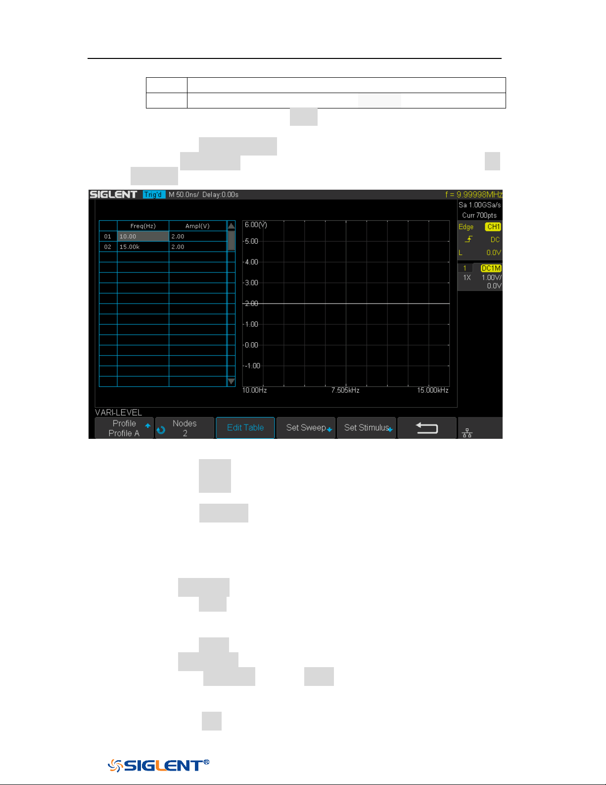
SDS1000X-E&SDS1000X-U User Manual
224
WWW.SIGLENT.COM
Device via a USB cable.
LAN
Connect the oscilloscope and the external AWG via LAN.
If LAN is selected, press the Set IP softkey, and set the IP of AWG in the
pop-up dialog box.
Press the Connection Test softkey to check the connection.
2) Press the Sweep Type softkey to select Simple or Vari-level. Press the Set
Vari-level softkey to enter the VARI-LEVEL menu.
Figure 151 VARI-LEVEL Menu
Press the Profile softkey to select the profile (Profile A~ Profile D).
Press the Nodes softkey and turn the Universal knob to set the number
of nodes.
Press the Edit Table softkey continuously to select the cell and turn the
Universal knob to select the line. When the cell is selected, set the
value by using the universal knob or virtual keyboard. "Freq" indicates
the scanning frequency value while "Ampl" indicates the scanning
amplitude.
3) Press the Set Sweep softkey to enter SET SWEEP menu.
Press the Mode softkey to select the sweep mode.
Linear: it is necessary to set the center frequency and span frequency
Decade: it is necessary to set the start frequency and stop frequency.
Press the Points softkey to set the sweep resolution.
4) Press the Set Stimulus softkey to enter STIMULUS menu.
Press the Amplitude softkey (Offset softkey) and turn the Universal
Knob to set the amplitude, or press the Universal Knob directly to enter
the parameter value in the pop-up virtual keyboard.
Press the Unit softkey and turn the Universal Knob to select the unit
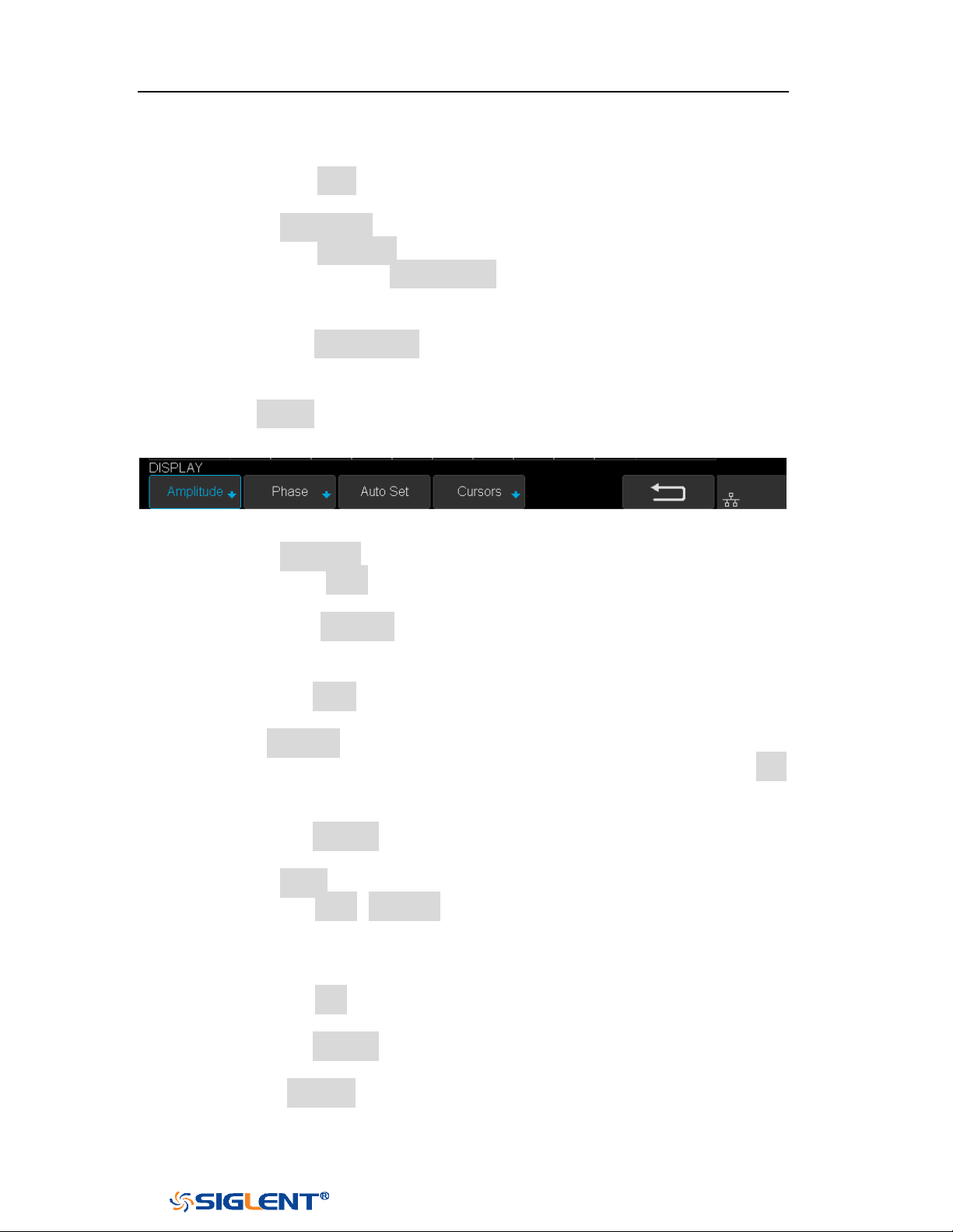
SDS1000X-E&SDS1000X-U User Manual
225
WWW.SIGLENT.COM
type. It contains 6 types of Vpp, Vrms, dBV, dBu, dBm, Arbitrary dB.
When the unit type is dB, it is necessary to set the reference level.
Press the Load soft key to switch the load between 50Ω, 75Ω, 600Ω,
Hi-Z. It also can turn the Universal Knob to set the load value.
5) Press the Set Channel softkey to enter the SET CHANNEL menu.
Press the DUT Input softkey to select the corresponding input signal
channel. Press the DUT Output 1 soft key to select the corresponding
output signal channel, and support up to 3 channels as the signal
output.
Press the Channel Gain softkey continuously to select the gain type as
“Hold” or “Auto”.
2. Press the Display soft key to enter the DISPLAY menu. The display menu
displays the configuration related to bode plot interface.
Figure 152 DISPLAY Menu
1) Press the Amplitude softkey to enter the AMPLITUDE menu.
Press the Scale softkey and turn the Universal Knob to set the
amplitude display scale.
Press the Ref Level softkey and turn the Universal knob to set the
amplitude display reference level, or press the Universal knob directly
to enter the value in the pop-up virtual keyboard.
Press the Mode softkey to set the display mode of the amplitude.
Vout/Vin: display the ratio of the DUT output to the DUT input. Press
the Axis Type softkey to set the vertical axis to logarithmic or linear.
Vout: display the DUT output voltage value directly. Press the unit
softkey to set the unit type to Vpp, Vrms, dBV, dBu, dBm, or Arbitrary
dB.
Press the Auto Set softkey to automatically adjust the vertical direction
parameters based on the Bode plot data.
2) Press the Phase softkey to enter the PHASE menu.
Press the Scale (Ref Level) softkey and turn the Universal Knob to set
the phase display scale (phase display reference level), or press the
Universal Knob directly to enter the value in the pop-up virtual
keyboard.
Press the Unit softkey continuously to switch the phase unit to Deg or
Rad.
Press the Auto Set softkey to automatically adjust the vertical direction
parameters based on the Bode plot data.
3) Press the Auto Set softkey to automatically adjust the vertical direction
parameters based on the Bode plot data.
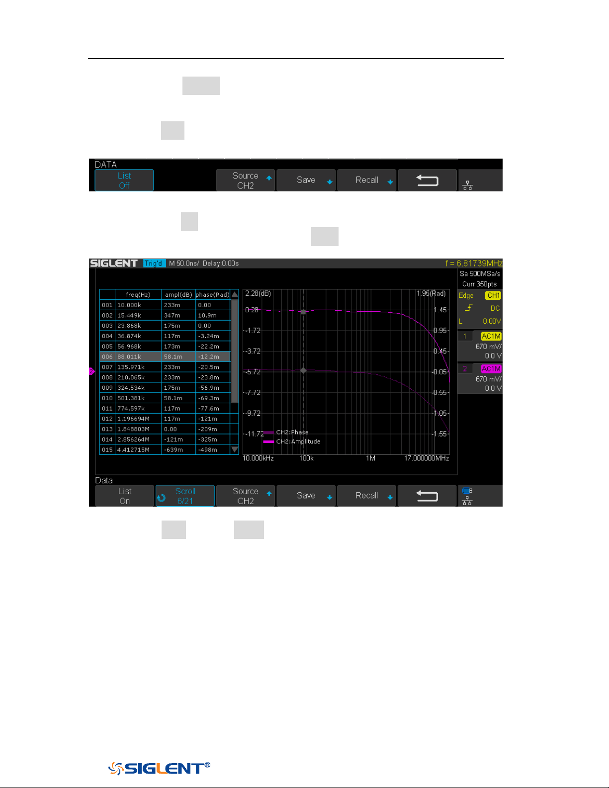
SDS1000X-E&SDS1000X-U User Manual
226
WWW.SIGLENT.COM
4) Press the Cursors soft key to enter the CURSORS menu. See the chapter
"Cursor" for details.
3. Press the Data softkey to enter the DATA menu. The data menu displays the
configurations of bode plot measurement results.
Figure 153 DATA Menu
1) Press the List softkey repeatedly to turn the Bode plot data list on or off.
After turning on the list, press the Scroll soft key and turn the Universal
Knob to select the frequency point, as shown below.
Figure 154 Bode Plot List On
2) Press Save softkey (Recall softkey) to enable the bode plot save (recall)
function. See the chapter “Save and Recall” for details.
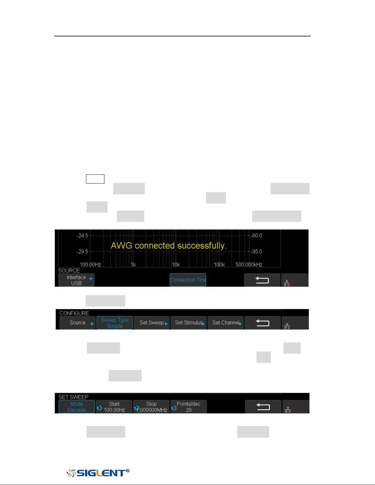
SDS1000X-E&SDS1000X-U User Manual
227
WWW.SIGLENT.COM
Example
The following are examples to familiarize you with bode plot.
Simple Sweep Operation
Vari-level Sweep Operation
Simple Sweep Operation
1. Press
Utility button on the front panel to enter the UTILITY function menu, and
then press the Next Page soft key to enter the second page. Press Bode Plot Ⅱ
to enter the BODE PLOT function menu. Press Config to enter Configure menu.
2. Press Source to enter Source menu to select the waveform generator. In this
example, press Interface to select “USB”, and then press Connection Test to
verify setting. Then return to the Configure menu.
Figure 155 Bode Plot Interface Connection
3. Press Sweep Mode to select “Simple”.
Figure 156 Sweep Configure Menu
4. Press Set Sweep to enter Set Sweep menu. In this example, press Mode to
select “Decade” to sweep frequency logarithmically. Press Start and use the
Universal Knob to set the start frequency to 100 Hz. Then set stop frequency to
1 MHz. Press Points/dec and use the Universal Knob to set the frequency point
to 20 points per decade. Then return to the Configure menu.
Figure 157 Set Sweep Parameters Menu
5. Press Set Stimulus to enter Set Stimulus menu. Press Amplitude and use the
Universal Knob to set the signal amplitude to 2 V. All the other options remain
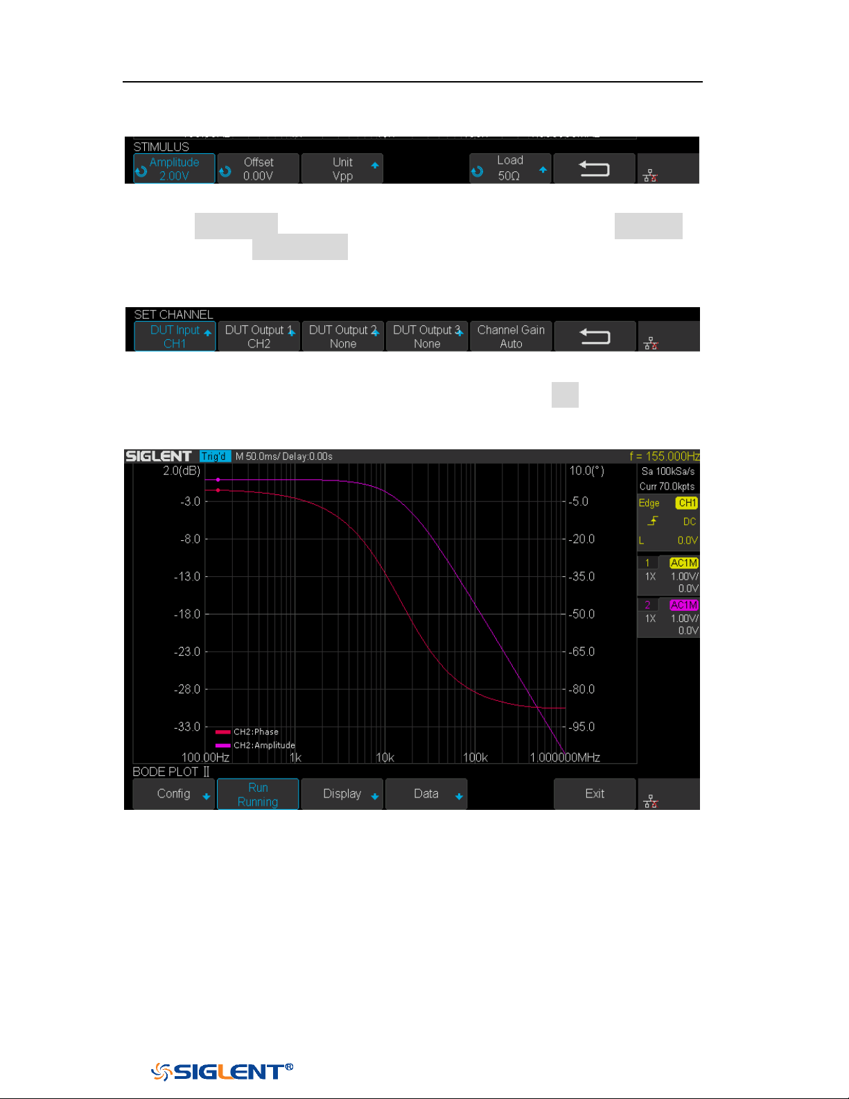
SDS1000X-E&SDS1000X-U User Manual
228
WWW.SIGLENT.COM
their default setting. Then return to the Configure menu.
Figure 158 Set Stimulus Menu
6. Press Set Channel to enter Set Channel menu. In this example, set DUT Input to
“CH1”, and DUT Output 1 to “CH2”. Other DUT Output remains “None”.
Since we want to maximize measurement dynamic range, set Channel Gain to
“Auto”. Then return to the Configure menu.
Figure 159 Set Channel Menu
7. Configuration was done. Return to root menu and press Run, and wait for the
sweep to complete.
Figure 160 Bode Plot Sweep Curve
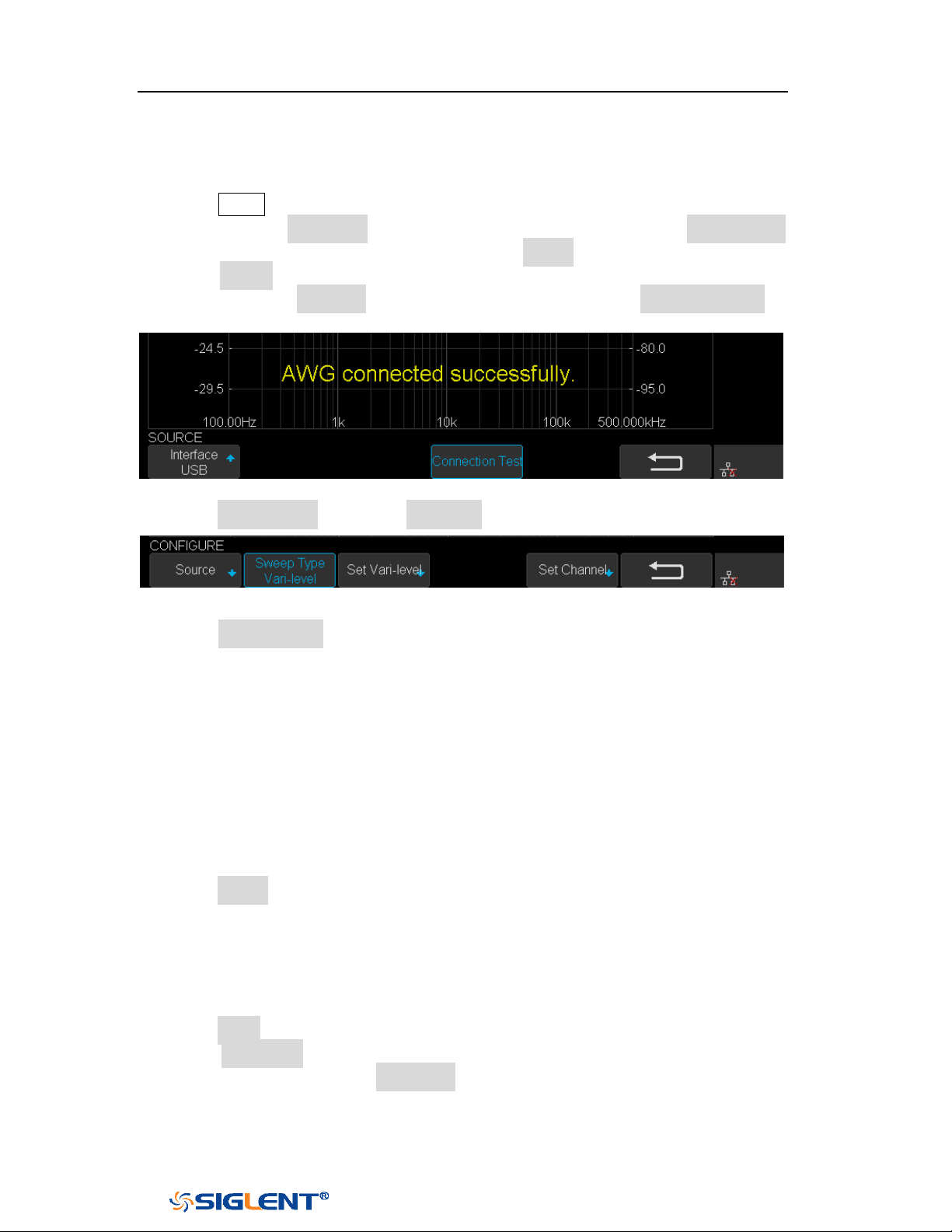
SDS1000X-E&SDS1000X-U User Manual
229
WWW.SIGLENT.COM
Vari-level Sweep Operation
1. Press Utility button on the front panel to enter the UTILITY function menu, and
then press the Next Page soft key to enter the second page. Press Bode Plot Ⅱ
to enter the BODE PLOT function menu. Press Config to enter Configure menu.
2. Press Source to enter Source menu to select the waveform generator. In this
example, press Interface to select “USB”, and then press Connection Test to
verify setting. Then return to the Configure menu.
Figure 161 Bode Plot Interface Connection
3. Press Sweep Mode to select “Vari-level”.
Figure 162 Vari-level Configure Menu
4. Press Set Vari-level to enter Vari-level editor. On the left side of the editor is a
spreadsheet which is used to specify the relationship between frequency and
amplitude. On the right side is an automatically generated stimulus voltage vs.
frequency plot.
5. The operation principle of Vari-level is simple. User specifies a series of joint,
which is defined by a given frequency and corresponding amplitude. In
between two adjacent joints, the frequency points and their corresponding
amplitude are calculated automatically by linear interpolation. The frequency
of the joints is sequential, so the frequency of the posterior joint is always
higher than the frequency of the anterior joint. And always, the first and the
last joint defines the start and stop frequency.
6. Press Profile and use the Universal Knob to select “Profile A”. As you can see,
up to 4 profiles can be saved.
7. In this example, I will demonstrate how to specify a Vari-level profile widely
used in testing power supply loop response. The profile is a 4-joint- polyline
with large stimulus amplitude in low frequency and small amplitude in high
frequency, and gradual amplitude in intermediate frequency.
8. Press Joints and use the Universal Knob to set the number of joint to 4.
9. Press Edit Table to activate the spreadsheet editor. When the spreadsheet
editor is activated, press Edit Table will cycle the cursor between frequency,
amplitude and the entire column. Then use the Universal Knob to adjust the
frequency, the amplitude, or to select the column to be edited. Press the
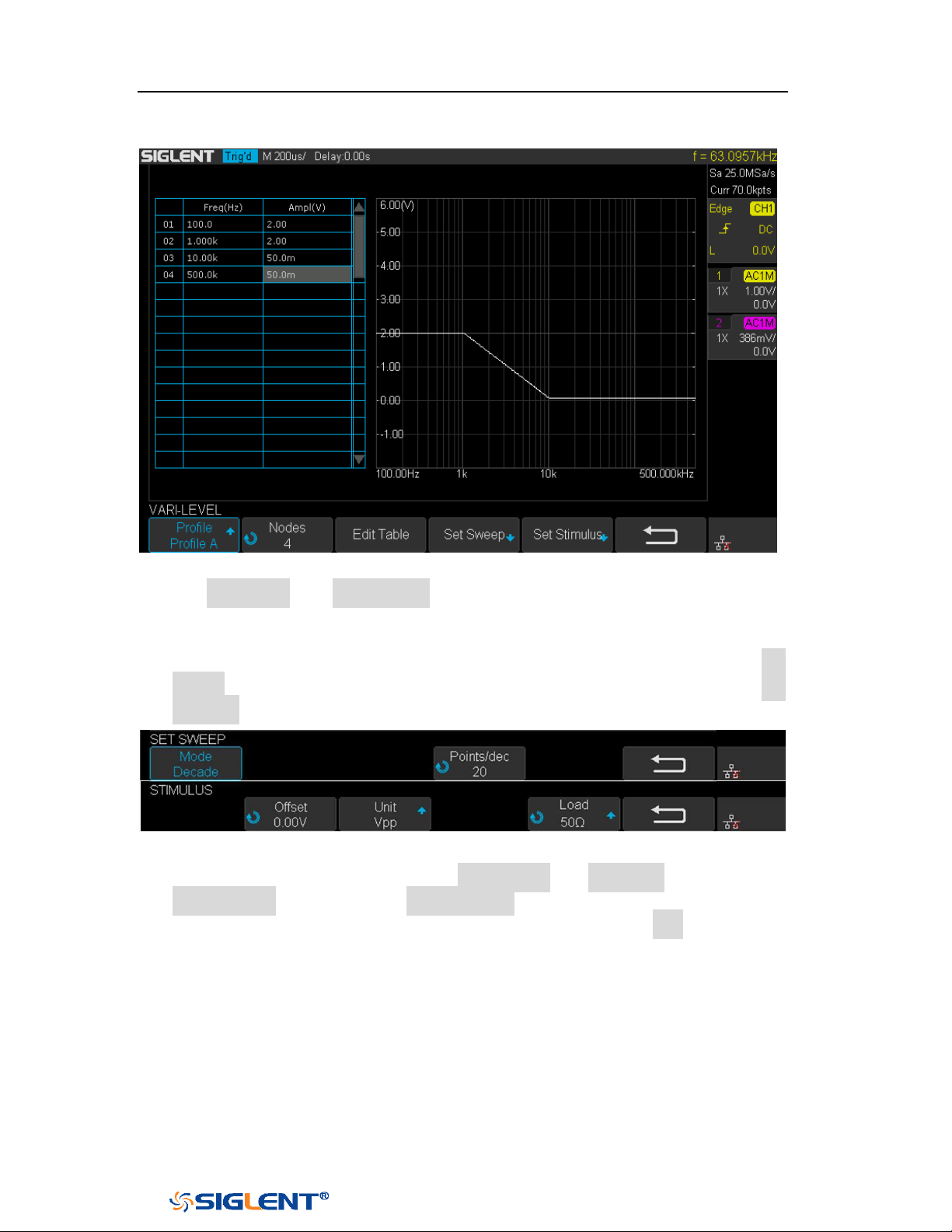
SDS1000X-E&SDS1000X-U User Manual
230
WWW.SIGLENT.COM
Universal Knob will activate the visual keypad for more precise input.
Figure 163 Set Vari-level Parameters Menu
10. The Set Sweep and Set Stimulus in Vari-level editor are similar to that in the
Simple sweep mode, but they are independently configured and do not affect
each other. These options in Vari-level mode do not have frequency and
amplitude input because they are specified in the spreadsheet. Press Set
Sweep and then set Mode to “Decade”, and set Points/dec to 20. The Set
Stimulus remains default setting.
Figure 164 Set Sweep Parameters Menu
11. Return to Configure menu and press Set Channel. Set DUT Input to “CH1” and
DUT Output 1 to “CH2”, and Channel Gain to “Auto”.
12. Configuration was done. Return to the root menu and press Run and wait for
the sweep to complete.
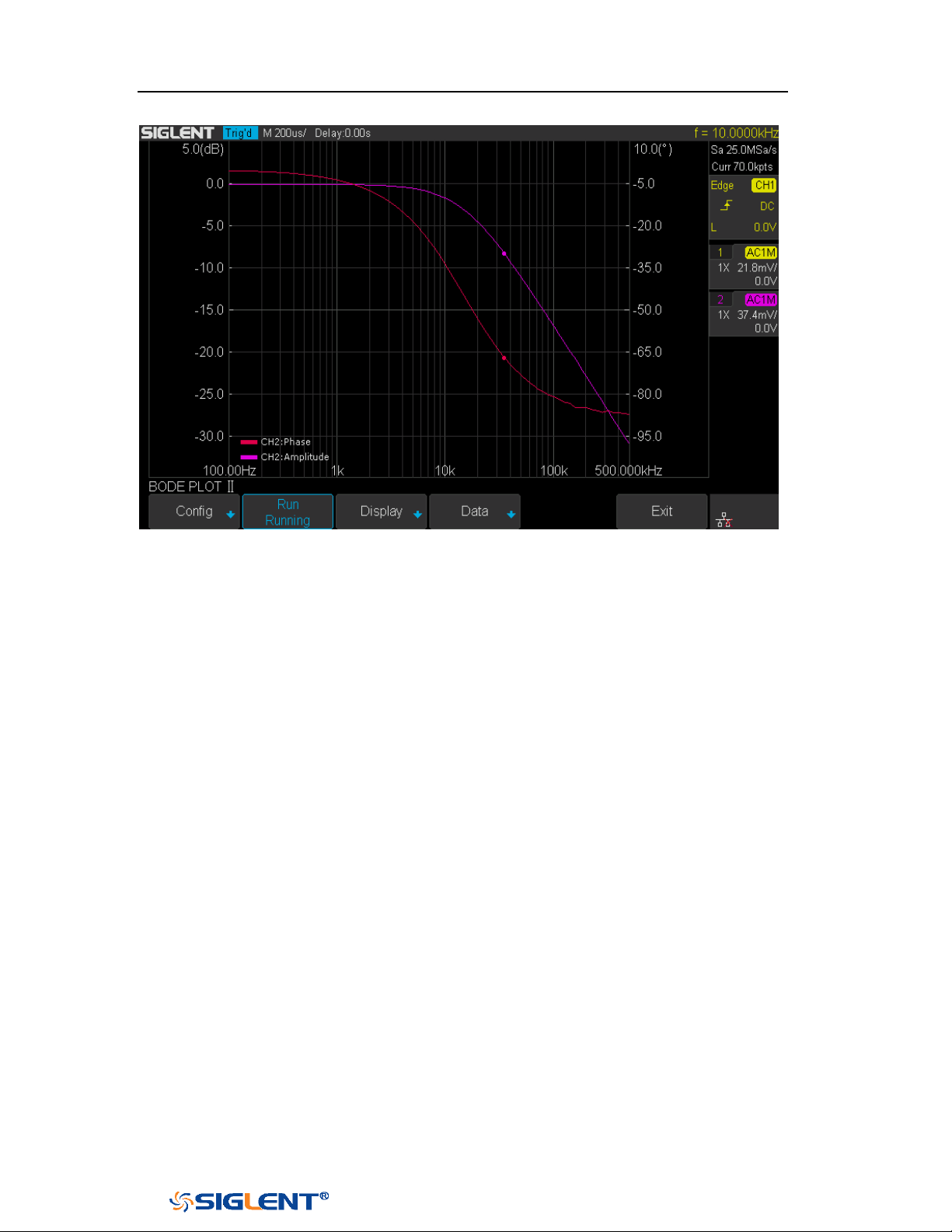
SDS1000X-E&SDS1000X-U User Manual
231
WWW.SIGLENT.COM
Figure 165 Bode Plot Sweep Curve
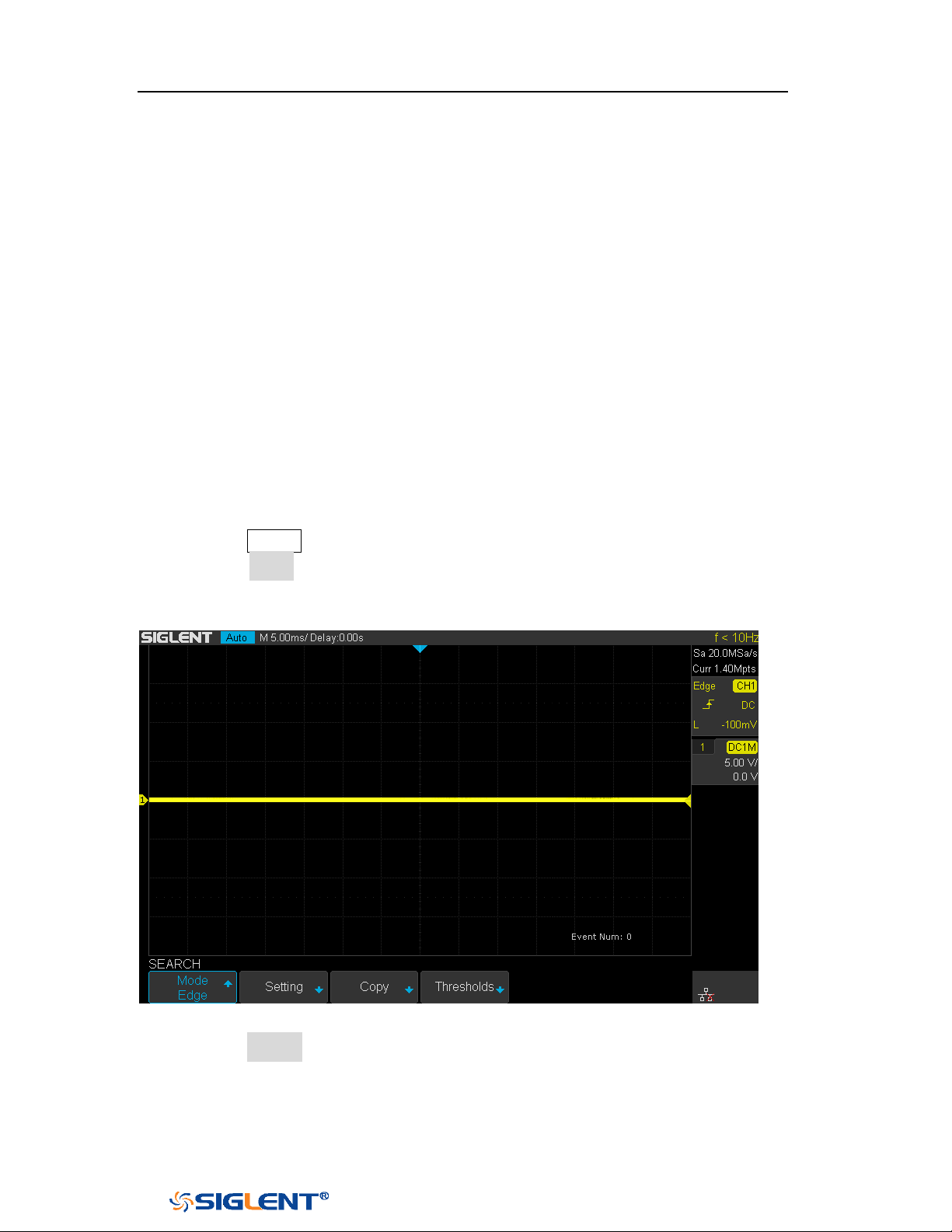
SDS1000X-E&SDS1000X-U User Manual
232
WWW.SIGLENT.COM
Search
SDS1000X-E (4-channel)and SDS1000X-U provide search function. This function
can search for the events that users specify in the acquired data, the results are
displayed with white triangle symbol. In the YT mode or the Roll mode with the
acquisition in stop, the maximum search events number is 700.In the Roll mode
with acquisition in run, the maximum search events number is unlimited. The
waveform can be zoomed when search function is enabled.
Setting
1. Press the
Search button on the front panel to enter the SEARCH function menu.
2. Press the Mode softkey and then use the Universal Knob to select the desired
search type. SDS1000X-E and SDS1000X-U provide five search types: Edge,
Slope, Pulse, Interval and Runt.
Figure 166 Search Menu
3. Press the Setting softkey to enter the SETTING function menu. The setting menu
is different according to every search type. The details show as the following
table.

SDS1000X-E&SDS1000X-U User Manual
233
WWW.SIGLENT.COM
Search Mode
Setting Menu Description
Edge
Slope includes Rising, Falling, Either.
Slope
Slope includes Rising, Falling
Limit Range includes four types: <=, >=, [--,--] and --] [--, Users
can select the desired type and then input the time value.
Pulse
Polarity includes Positive and Negative
Limit Range includes four types: <=, >=, [--,--] and --] [--, Users
can select the desired type and then input the time value.
Interval
Slope includes Rising, Falling
Limit Range includes four types: <=, >=, [--,--] and --] [--, Users
can select the desired type and then input the time value.
Runt
Polarity includes Positive and Negative
Limit Range includes four types: <=, >=, [--,--] and --][-- , Users
can select the desired type and then input the time value
4. Press the Copy Setting softkey to enter COPY function menu.
Copy from Trig: copy the trigger setup for the selected search type to the
search setup.
Copy to Trig: copy the setup for the selected search type to the same trigger
type.
Cancel Copy: undo a copy.
5. Press the Thresholds softkey to enter THRESHOLDS function menu, then, to set
channel search thresholds.
Results
When the acquisition is started, “EVENT NUM: 7” means total events number.
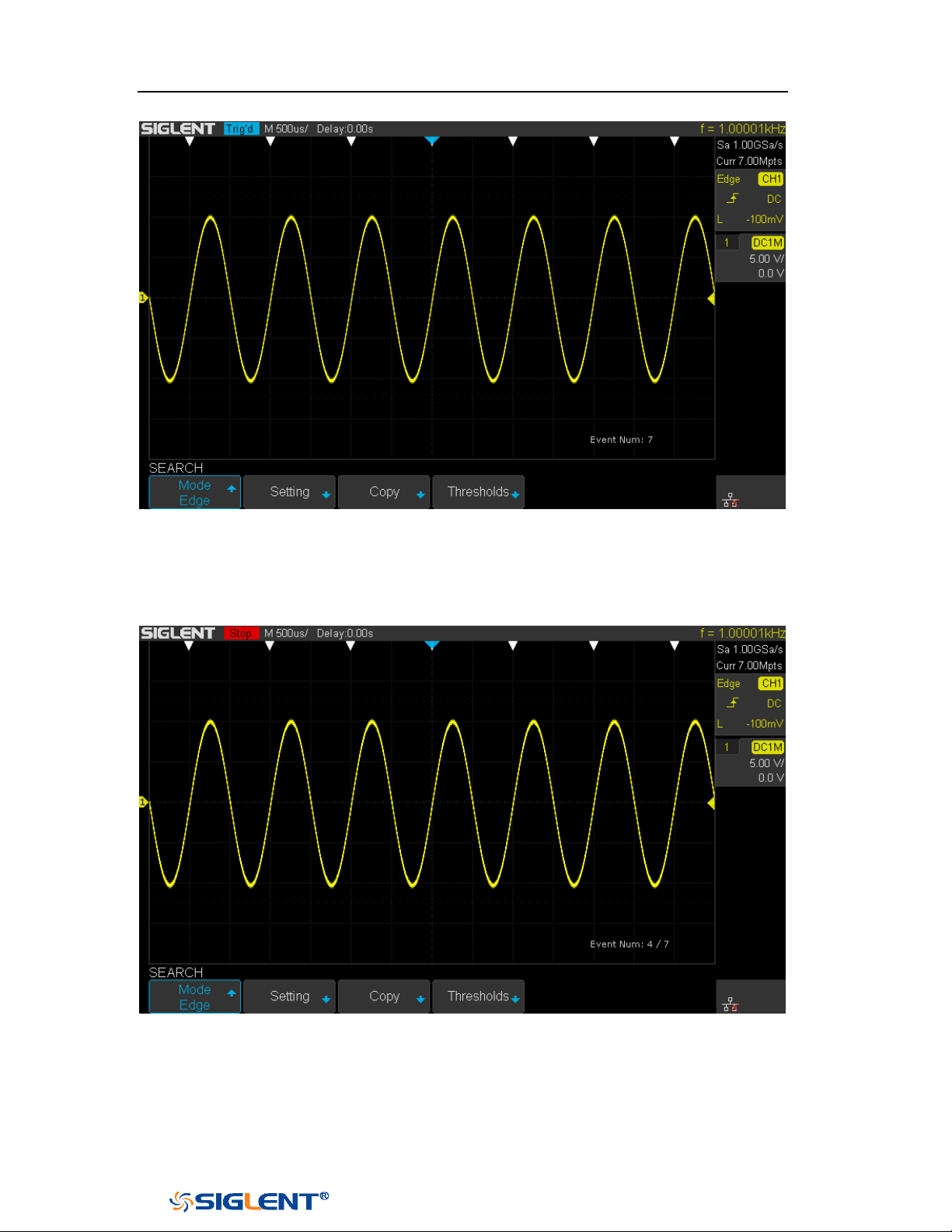
SDS1000X-E&SDS1000X-U User Manual
234
WWW.SIGLENT.COM
Figure 167 Search in Run
When the acquisition is stop, “EVENT NUM: 4/7” means current event
number/total events number, the current event is the closest event to the middle of
the screen.
Figure 168 Search in Stop

SDS1000X-E&SDS1000X-U User Manual
235
WWW.SIGLENT.COM
Navigate
SDS1000X-E(4-channel) and SDS1000X-U provide three navigate type: Search
Event, Time, History Frame.
Time Navigate
1. Press the Navigate on the front panel to enter the NAVIGATE function menu.
2. Press the Type softkey In the NAVIGATE function menu, then select Time.
3. There are two ways to navigate time.
a. Press the Time softkey, then, turn the Universal Knob to select the desired
value or press the Universal Knob then enter the value by the pop
keyboard.
b. Press the navigation keys ◀■▶ on the front panel to play backward, stop,
or play forward in time. You can press the ◀ or ▶ keys multiple times to
speed up the playback. There are three speed levels: Low Speed, Medium
Speed, and High Speed.
History Frame Navigate
When the History function is enabled, you can use the navigation controls to play
through the acquired frames.
1. Press the Navigate on the front panel to enter the NAVIGATE function menu.
2. Press the Type softkey in the Navigate Menu, then select History Frame.
3. Press the Frame Num softkey, then there are two ways to navigate history
frames.
a. Turn the
Universal Knob to select the desired number or press the
Universal Knob then enter the number by the pop keyboard.
b. Press the navigation keys ◀■▶ on the front panel to play backward, stop,
or play forward.

SDS1000X-E&SDS1000X-U User Manual
236
WWW.SIGLENT.COM
Search Event Navigate
When the Search function is enabled and acquisitions are stopped, you can use the
navigation controls to go to found search events
1. Press the Navigate on the front panel to enter the NAVIGATE function menu.
2. Press the Type softkey in the NAVIGATE function menu, then select Search
Event.
3. There are two ways to navigate search events.
a. Press the Event Num softkey, then, turn the Universal Knob to select the
desired value or press the Universal Knob then enter the value by the pop
keyboard.
b. Press the
Navigate keys ◀ ▶ on the front panel to go to the previous or
next search event.
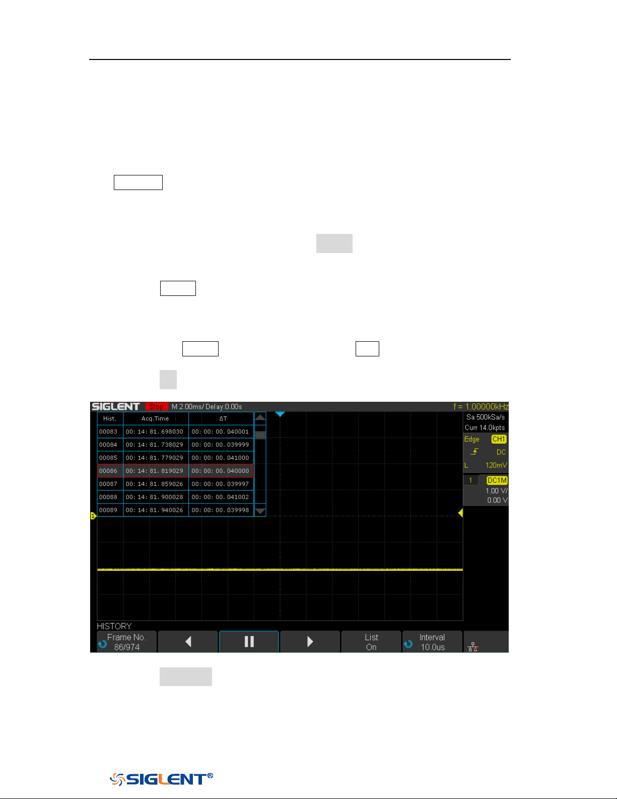
SDS1000X-E&SDS1000X-U User Manual
237
WWW.SIGLENT.COM
History
The history function can record the waveforms of the input channels before press
the
Run/Stop button. In run state, the oscilloscope records input waveform
continually; when fill up the memory (reach the maximal frame), the new frames
will cover the old frames and keep the latest frames.
To use the History function, the HORIZONTAL Format must be set to YT.
Do the following steps to record and replay waveform:
1. Press the
History button on the front panel to enable the History function.
When in run state, the waveform will enter the stop state.
When in stop state, and then enable the History function, the oscilloscope
will keep the stop state.
Press the History button again or press the Stop button to turn off History
function.
2. Press the List softkey to turn on or off the list display. The list records the
timestamp of every frame. It is accurate to microseconds.
Figure 169 History
3. Press the Frame No. softkey; then turn the Universal Knob to select the frame to
display.
The format of the
Frame is A/B; A is the frames number that displaying on
the screen and B is the maximal frame number you can set.
The maximal frame number is determined by the current sampling point
SDS1000X-E&SDS1000X-U User Manual
238
WWW.SIGLENT.COM
(Curr value) and sampling rate.
When press the Run/Stop button or enable the history function, you may
not get the maximal frames, because the memory is not filled. So if you
want to get the maximal frames, please wait for enough time for
acquisition.
4. Press the softkey to replay the waveform from the current frame to 1.
5. Press the softkey to stop replay.
6. Press the softkey to replay the waveform from the current frame to the
last frame.

SDS1000X-E&SDS1000X-U User Manual
239
WWW.SIGLENT.COM
Factory Setup
Press Save/Recall function key, then press Save menu select To Default Key set the
type to Factory Setup. Then press the Default button on the front to set the
oscilloscope to the leave factory setup. Another way is press Save/Recall function
key, then press Recall menu select Factory Default to recall.

SDS1000X-E&SDS1000X-U User Manual
240
WWW.SIGLENT.COM
Troubleshooting
The commonly encountered failures and their solutions are listed below. When you
encounter those problems, please solve them following the corresponding steps. If
the problem remains still, please contact
SIGLENT Company as soon as possible.
1. The screen is still dark (no display) after power on:
1) Check whether the power is correctly connected.
2) Check whether the power switch is really on.
3) Check whether the fuse is burned out. If the fuse needs to be changed,
please use the specified fuse.
4) Restart the instrument after finishing the above inspections.
5) If it still does not work correctly, please contact
SIGLENT.
2. The signal is sampled but no waveform of the signal is displayed:
1) Check whether the probe is correctly connected to the signal connecting
wire.
2) Check whether the signal connecting wire is correctly connected to the BNC
(namely channel connector).
3) Check whether the probe is correctly connected to the item to be tested.
4) Check whether there are signals generated from the item to be tested (you
can connect the probe compensation signal to the problematic channel to
determine which has problem, the channel or the item to be tested).
5) Resample the signal.
3. The tested voltage amplitude is greater or lower than the actual value (note that this
problem usually occurs when probe is used):
Check whether the attenuation coefficient of the channel complies with the
attenuation ratio of the probe.
4. There is waveform display but not stable:
1) Check the trigger signal source: check whether the Source item at the
trigger panel complies with the signal channel actually used.
2) Check the trigger type: general signals should use “Edge” trigger and
video signal should use “Video” trigger. Only when the proper trigger
type is used, can the waveform be displayed stably.
3) Change the trigger holdoff setting.
5. No display after pressing Run/Stop:
Check whether the mode at the trigger panel (TRIGGER) is on “Normal” or

SDS1000X-E&SDS1000X-U User Manual
241
WWW.SIGLENT.COM
“Single” and whether the trigger level exceeds the waveform range. If yes,
set the trigger level to the middle or set the mode to “Auto”.
Note: using AUTO could automatically finish the above setting.
6. The display of waveform is ladder-like:
1) The horizontal time base might be too low. Increase the horizontal time
base to increase the horizontal resolution and improve the display.
2) If the display Type is “Vectors”, the lines between the sample points may
cause ladder-like display. Set Type to “Dots” to solve the problem.
7. Fail to connect PC through USB:
Check the IO Setting in Utility to make sure whether the setting in USB Device
matches the device currently connected. If needed, restart the oscilloscope.
8. The USB storage device cannot be recognized:
1) Check whether the USB storage device can work normally.
2) Make sure whether the USB interface can work normally.
3) Make sure that the USB storage device being used is flash storage type.
This oscilloscope does not support hardware storage type.
4) Restart the instrument and then insert the USB storage device to check it.
5) If the USB storage device still cannot be used normally, please contact
SIGLENT.

SDS1000X-E&SDS1000X-U User Manual
242
WWW.SIGLENT.COM
SDS1000X-E
SDS1000X-U
Digital Oscilloscope