
User Manual
SDG800 Series Function/Arbitrary Waveform Generator
UM02008-E02B
2014 SIGLENT TECHNOLOGIES CO., LTD

SDG800 User Manual I
Declaration
Copyright © SIGLENT TECHNOLOGIES CO., LTD. All rights reserved.
Contents in this Manual are not allowed to be copied, extracted and
translated before being allowed by SIGLENT Company

SDG800 User Manual II
General Safety Summary
Review the following safety precautions to avoid injury and prevent damage
to this product or any products connected to it. To avoid potential hazards,
use this product only as specified.
Only qualified personnel should perform service procedures.
To Avoid Fire or Personal Injury
Use proper power line. Only the special power line of the products
approved by the state should be used.
Ground the instrument. This generator is grounded through the
protective terra conductor of the power cord. To avoid electric
shock, the grounding conductor must be connected to the earth
ground. Make sure that the instrument is properly grounded before
connecting the input or output terminals.
Observe all the ratings of the terminal. To avoid fire or shock,
observe all the ratings and symbols that marked on the instrument.
Read the user guide carefully before making connections to the
instrument.
Do not operate without Covers. Do not operate the product with
covers or panels removed.
Avoid circuit or wire exposed. Do not touch the exposed
connections or components when the power is on.
Do not operate with suspected failures. If you suspect there is
damage with this product, you should have it inspected by
qualified service personnel authorized by SIGLENT before further
operations.

SDG800 User Manual III
Provide proper ventilation.
Do not operate in wet/damp conditions.
Do not operate in an explosive atmosphere.
Keep the product’s surfaces clean and dry.
Not position the equipment so that it is difficult to operate the
disconnecting device (detachable plug)

SDG800 User Manual IV
If the equipment is used in a manner not specified by the manufacturer, the
protection provided by the equipment may be impaired.
This product has been tested to the requirements of
CAN/CSA-C22.2 No. 61010-1, second edition, including Amendment 1,
or a later version of the same standard incorporating the same level of
testing requirements.
Not to use the product for measurements within other measurement
categories, such as CAT II, CAT III, CAT IV.
Not to use the equipment for measurements on mains circuits, not to
use the equipment for measurements on voltage exceed the voltage
range describe in the manual.
Only probe assemblies which meet the manufacturer’s specifications
shall be used.
The Responsible body or operator should refer to the instruction
manual to preserve the protection afford by the equipment. If the
equipment is used in a manner not specified by the manufacturer, the
protection provided by the equipment may be impaired.
Any parts of the device and its accessories are not allowed to be
changed or replaced, other than authorized by the manufacturer of his
agent.
SDG800 User Manual V
Safety Terms and Symbols
Terms in this guide, these terms may appear in this manual:
Terms on the product, terms below may appear on the product:
DANGER: Indicates an injury or hazard that may immediately happen.
WARNING: Indicates an injury or hazard that may not immediately happen.
CAUTION: Indicates that a potential damage to the instrument or other
property might occur.
Symbols on the product: Symbols as followed may appear on the product:

SDG800 User Manual VI
Introduction of SDG800 Series
The manual covers the following three types of SDG800 Series
Function/Arbitrary Waveform Generators: SDG830,SDG810, SDG805.
SDG800 Series Function/Arbitrary Waveform Generators adopt the direct
digital synthesis (DDS) technology, which can provide stable, high-precision,
pure and low distortion signals. Its combination of excellent system features,
easiness in usage and versatile functions makes this generator a perfect
solution for your job now and in the future.
SDG800 Series Function/Arbitrary Waveform Generator has a clear and
simple front-panel. The user-friendly panel layout and instructions, versatile
terminals, direct graph interface, built-in instructions and help system have
greatly simplified the operation process, with the help of which, users do not
have to spend a great deal of time learning and familiarizing the operation of
the generator before they can use it proficiently. The built-in AM, DSB-AM,FM,
PM, ASK, FSK and PWM modulation functions generate modulated
waveforms at ease, without the help of a separate modulating source. USB
I/O is a standard accessory, while GPIB is optional. Remote instructions meet
the SCPI specification requirements.
From the characteristics and specifications given below, you will understand
how SDG800 can satisfy your requirements.

SDG800 User Manual VII
DDS technology provides precise, stable and low distortional
output signal.
3.5’TFT color LCD display.
125MSa/s sampling rate, 14-bit resolution.
Frequency characteristics:
Sine: 1μHz to 30MHz
Square: 1μHz to 10 MHz
Ramp: 1μHz to 300kHz
Pulse: 500μHz to 5MHz
White Noise: 10MHz bandwidth (-3dB)
Arbitrary: 1μHz to 5MHz
5 standard waveforms: Sine, Square, Ramp, Pulse, Noise
Self-defined arbitrary waveform
Multiple modulation function: AM, FM, PM, ASK, FSK, PWM,
DSB-AM, Sweep and Burst.
Multiple interfaces: USB host & USB device(USBTMC)
Support USB storage device. Software updating could also be
performed using USB devices.
Up to 16k sample points of internal waveform depth, which can
rebuild or simulate any complex waveform.
2 languages (English and Chinese) user interface and built-in help
system.
Note:
All the specifications described in this guide are according to SDG830. If you
need to know the particular specifications about the other types, please see
datasheet..

SDG800 User Manual VIII
Catalogue
General Safety Summary ................................................................................. II
Introduction of SDG800 Series ...................................................................... VI
1. Getting Started ........................................................................................... 1
1.1. General Inspection ........................................................................... 2
1.2. Handle Adjustment ........................................................................... 3
1.3. The Front/Rear Panel ....................................................................... 4
1.4. To Set a Waveform ........................................................................... 7
1.5. To Set Modulate/Sweep/Burst ........................................................ 12
1.6. To Set Output ................................................................................. 14
1.7. To Use Digital Input ........................................................................ 15
1.8. To Use Store/Utility/Help Function .................................................. 16
2. Operating Your Generator ........................................................................ 17
2.1. To Set Sine Signals ........................................................................ 18
2.2. To Set Square Signals .................................................................... 23
2.3. To Set Ramp Signals ...................................................................... 26
2.4. To Set Pulse Signals ...................................................................... 29
2.5. To Set Noise Signals ...................................................................... 33
2.6. To Set Arbitrary Signals .................................................................. 35
2.7. To Generate the Modulated Waveform ........................................... 42
2.8. To Generate Sweep ........................................................................ 51
2.9. To Generate Burst .......................................................................... 53
2.10. To Store and Recall ..................................................................... 57
2.11. To Set the Utility Function............................................................ 63
2.12. Test/Cal ....................................................................................... 74
2.13. Edition Information ...................................................................... 79
2.14. Updating Firmware ...................................................................... 81

SDG800 User Manual IX
2.15. How to Use the Built-in Help System .......................................... 82
3. Application and Examples ....................................................................... 83
3.1. Example 1:Generate a Sine Wave ................................................. 84
3.2. Example 2:Generate a Square Wave ............................................. 86
3.3. Example 3:Generate a Ramp Wave ............................................... 88
3.4. Example 4:Generate a Pulse Wave................................................ 90
3.5. Example 5:Generate a Noise Wave ............................................... 92
3.6. Example 6:Generate an Arbitrary Wave ......................................... 93
3.7. Example 7:Generate a Sweep Linear Wave ................................... 95
3.8. Example 8:Generate a Burst Wave ................................................ 97
3.9. Example 9:Generate an AM Wave ................................................. 99
3.10. Example 10:Generate a FM Wave ............................................ 101
3.11. Example 11:Generate a PM Wave ............................................ 103
3.12. Example 12:Generate a FSK Wave .......................................... 105
3.13. Example 13:Generate an ASK Wave ........................................ 107
3.14. Example 14: Generate a PWM Wave ........................................ 109
3.15. Example 15: Generate a DSB-AM Wave .................................. 111
4. Troubleshooting ..................................................................................... 113
General Inspecting ................................................................................ 113
Troubleshooting .................................................................................... 114
5. Service and Support .............................................................................. 115
Maintain summary................................................................................. 115
Contact SIGLENT ................................................................................. 116
6. Appendix ................................................................................................ 117
Appendix A: Accessories ....................................................................... 117
Appendix B: Daily Maintain and Cleaning ............................................. 118

SDG800 User Manual 1
1. Getting Started
This chapter covers the following topics:
General Inspection
Handle Adjustment
The Front/Rear Panel
To Set a Waveform
To Set Modulate/Sweep/Burst
To Set Output
To Use Digital Input
To Use Store/Utility/Help Function

SDG800 User Manual 2
1.1. General Inspection
When you get a new SDG800 Series Function/Arbitrary Waveform Generator,
you are suggested to take the following steps to inspect the instrument.
1. Inspect the shipping container for damage.
If there are damages in the packing or foam, keep them until the whole
machine and the accessories pass the electric and mechanical testing.
2. Check the accessories.
Accessories supplied with the instrument are listed in chapter 6
‘Appendix A: Accessories’.
If the contents are incomplete or damaged, please notify your sales
representative.
3. Inspect the instrument.
In case any mechanical damage or defect, or if the instrument does not
operate properly or pass performance tests, notify your sales
representative. If the shipping container is damaged, or the cushioning
materials show signs of stress, notify the carrier as well as your sales
office. Keep the shipping materials for the carrier’s inspection. Offices
will arrange for repair or replacement at their option without waiting for
claim settlement.
SDG800 User Manual 3
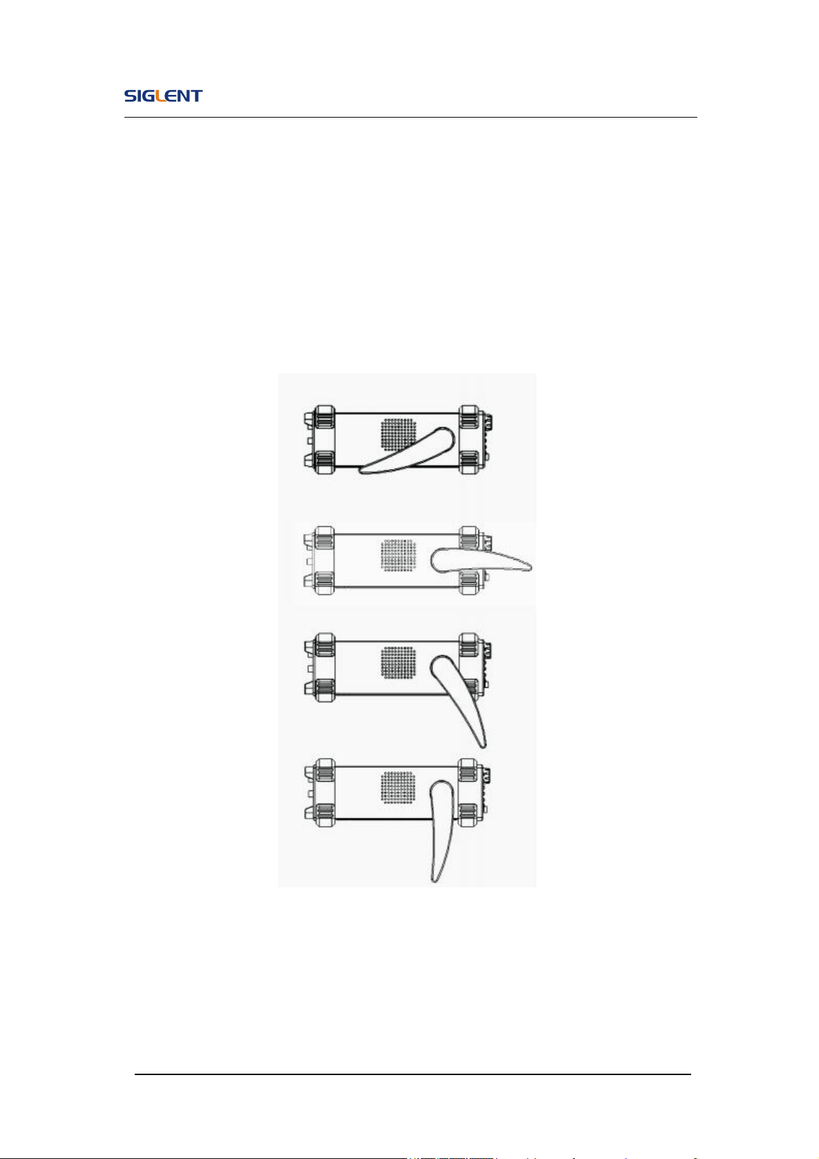
1.2. Handle Adjustment
To adjust the handle position of SDG800 Function/Arbitrary Waveform
Generator, please grip the handle by the sides and pull it outward. Then,
make the handle rotate to the desired position.
Figure 1- 1 Viewing Position and Carrying Position
SDG800 User Manual 4
1.3. The Front/Rear Panel
When you get a new SDG800 Series Function/Arbitrary Waveform Generator,
first you need to understand how to operate the front/rear panel correctly.
This chapter will make a brief introduction and description for the operation
and functions of the front/rear panel.
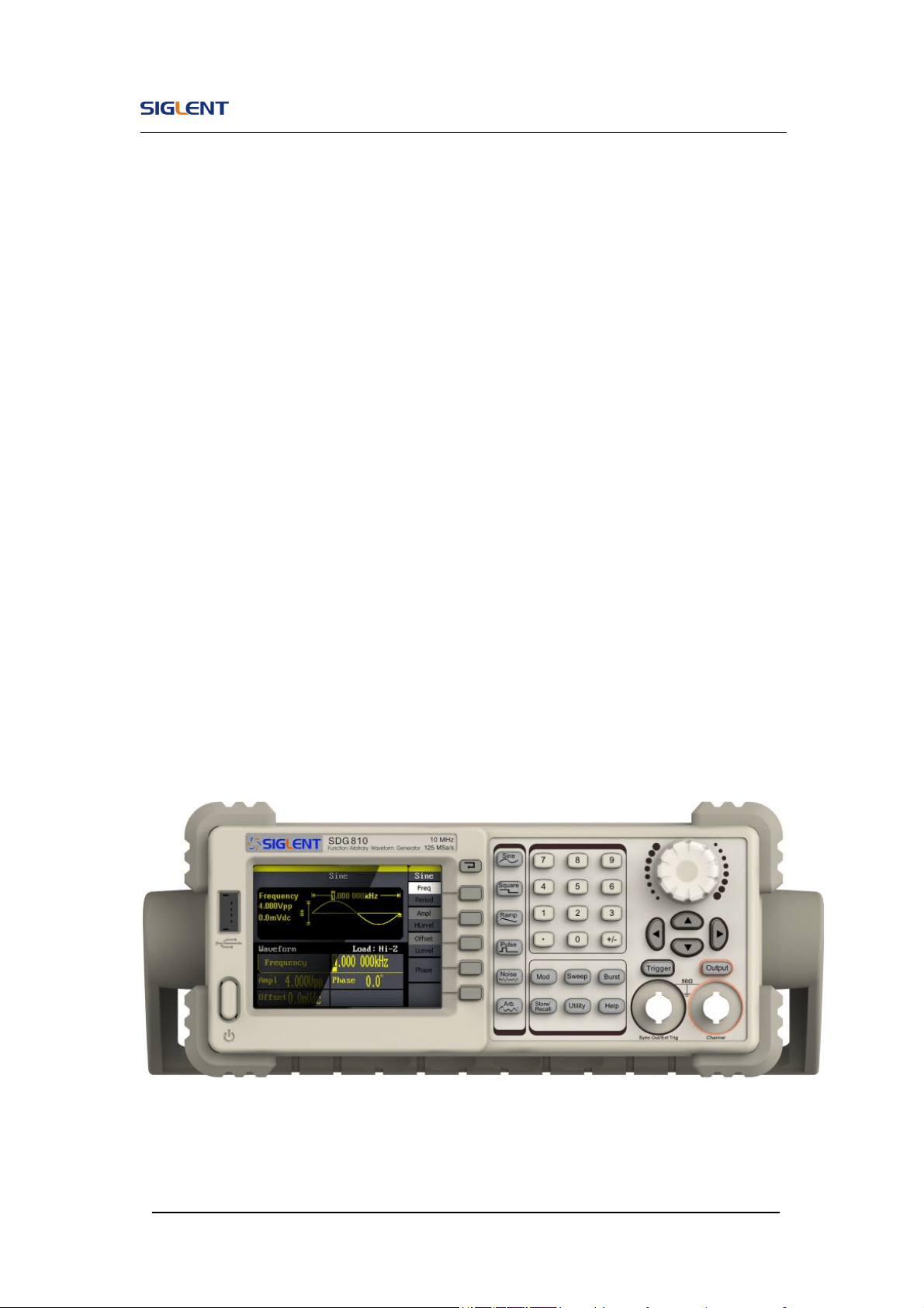
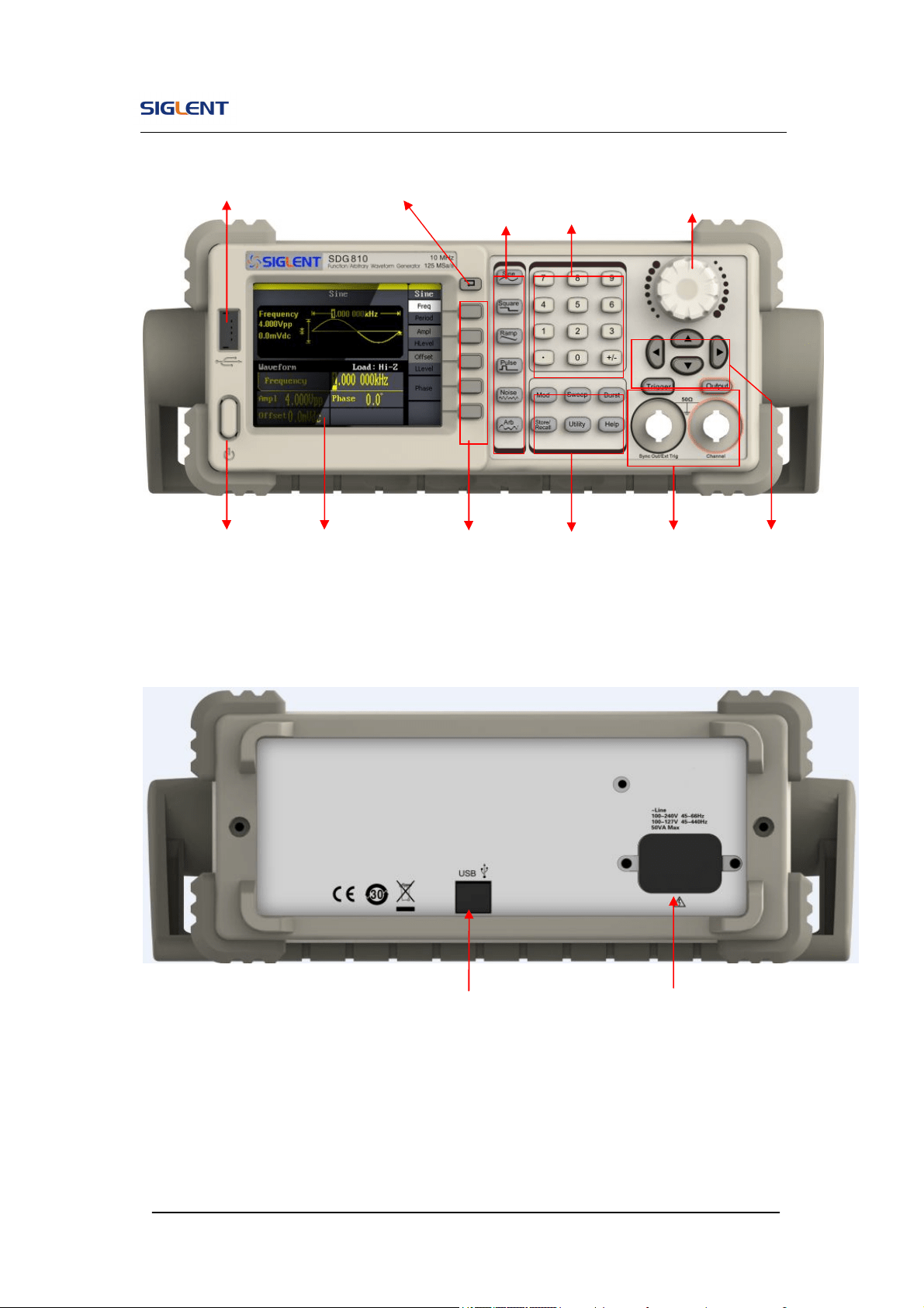
The SDG800 Series Function/Arbitrary Waveform Generator has a clear and
simple front panel. See Figure 1- 2 and Figure 1- 3. The front panel has a
knob and functional keys. The 5 blue grey buttons on the right side of the
screen are menu buttons (named F1 to F5 from up to down) with the help of
which, you can enter different functions menu or have direct specific
applications. The signal input and output interfaces are set at the front and
rear panels which can help generating multiple arbitrary waveforms. The
various interfaces can meet the need of the multiple interface
communications.
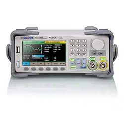
Figure 1- 2 SDG800 Series
SDG800 User Manual 5
Figure 1- 3 Front Panel of SDG800 Series
Figure 1- 4 Rear Panel of SDG800 Series
USB Device
Power Socket
USB Host
Waveform
keys
Number
keys
Knob
Power
LCD
Display
Menu
Operation Function
keys
Output
Control
Direction
keys
Back
SDG800 User Manual 6
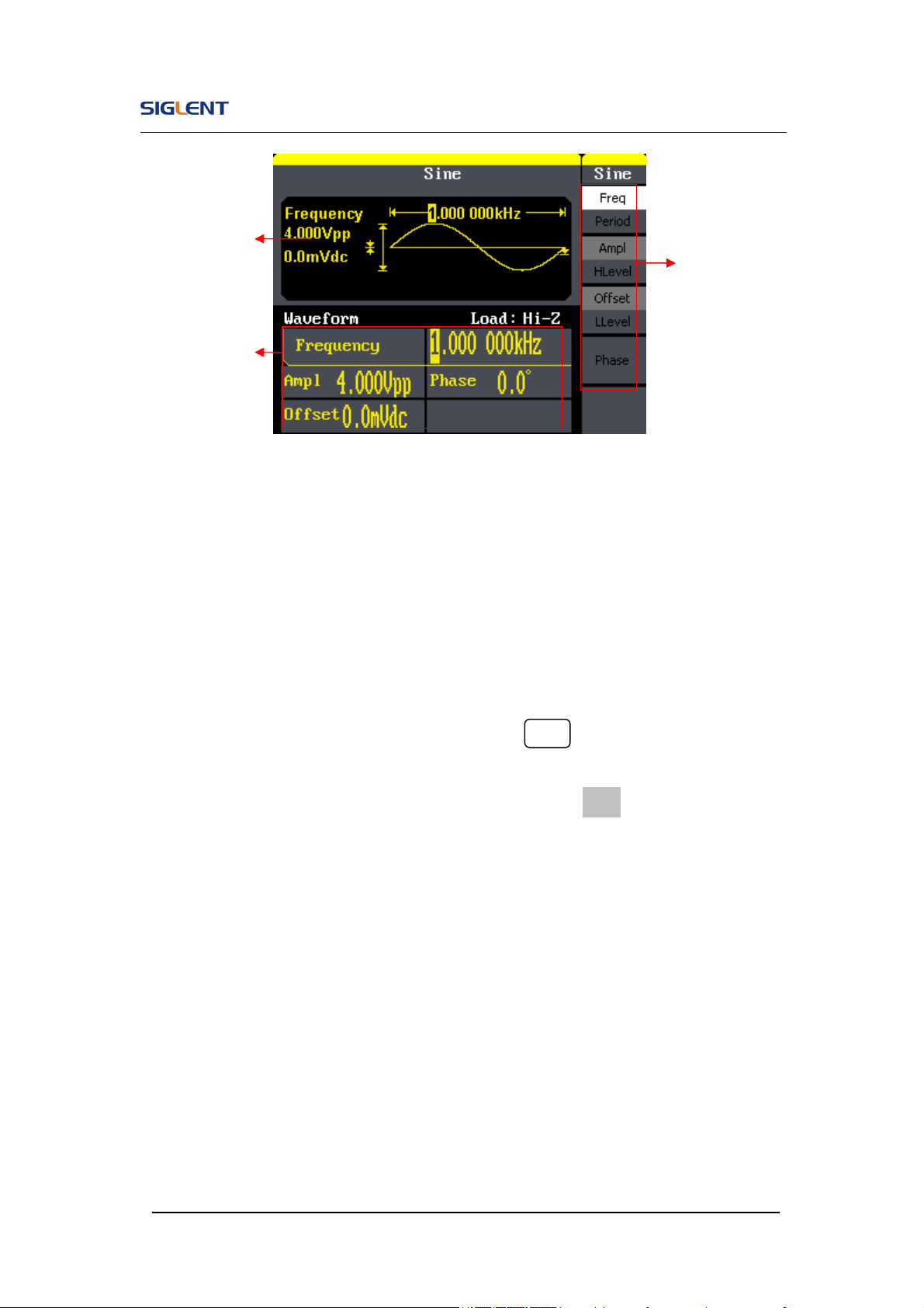
Figure 1- 5 Display Interface (Sine Wave is the default display signal)
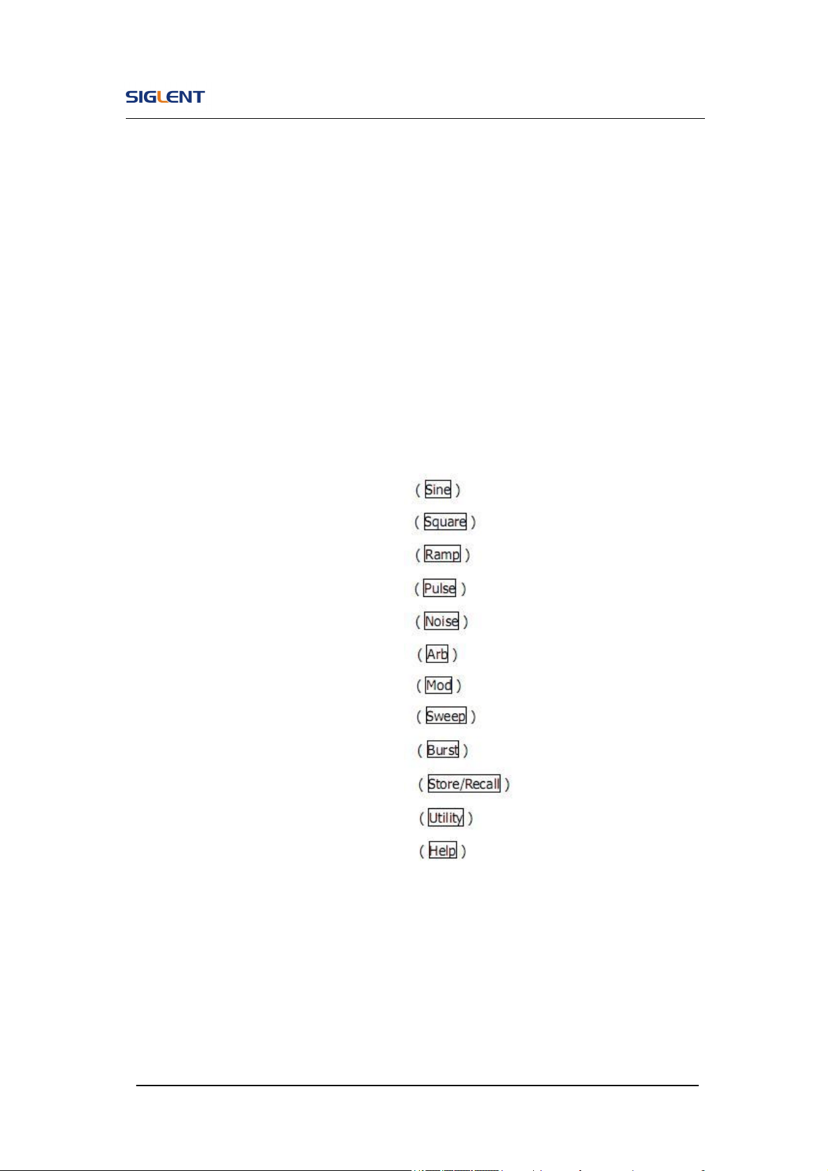
Character definitions in this User Manual:
The signs for buttons in this manual are the same as the panel buttons.
Please note that, the signs for the functional buttons on the operation panel
are represented by squared words, such as Sine , which represents the
transparent functional key with Sine on it on the front panel, while the menu
buttons are represented by brighten words such as Freq, which means the
frequency option in the Sine menu.
Waveform
Display area
Parameter area
Operation
Menu:
SDG800 User Manual 7
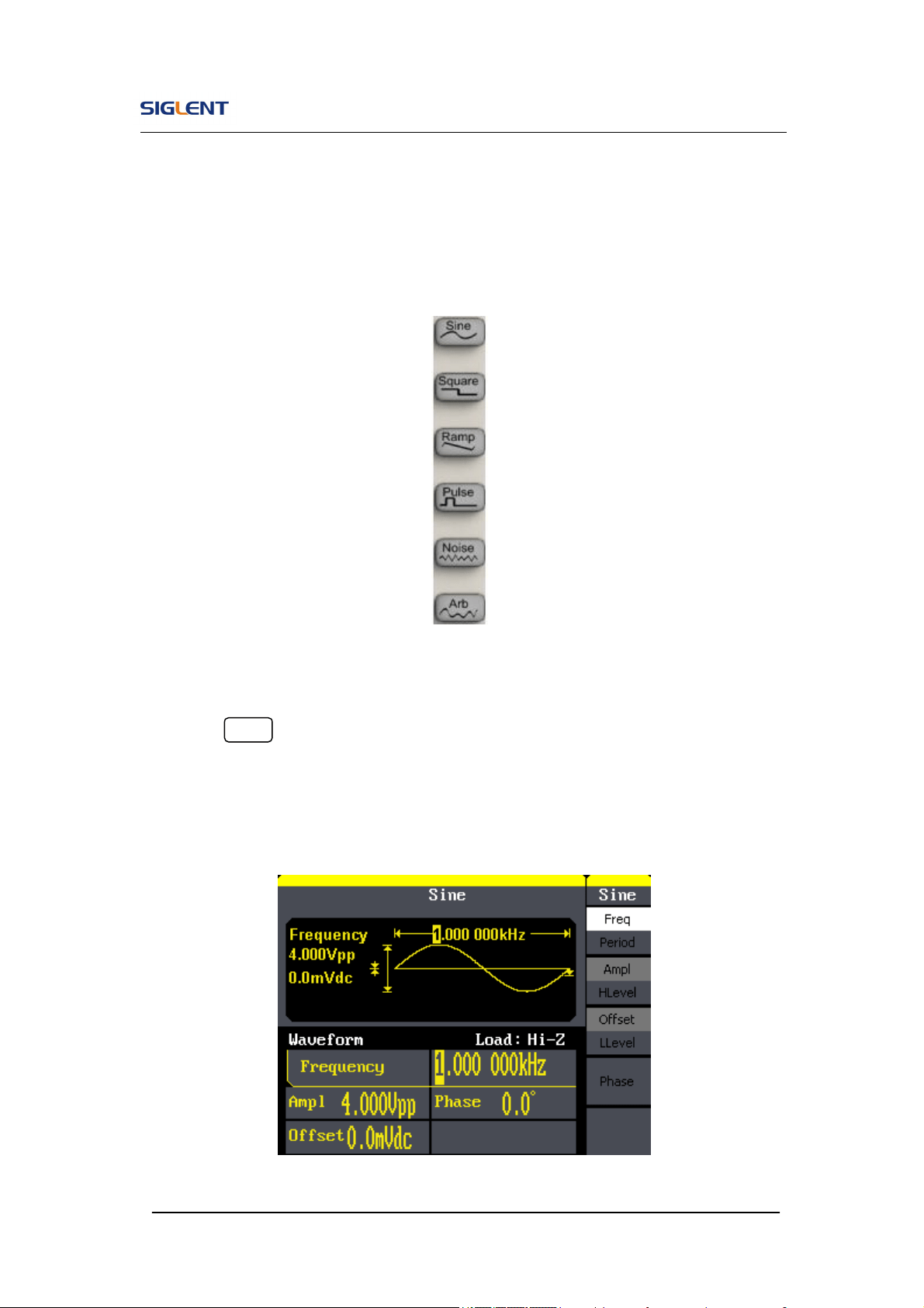
1.4. To Set a Waveform
On the operation panel, there is a set of buttons with waveform icon. See
Figure 1- 6. The exercise below will help you familiarize with the waveform
selection settings.
Figure 1- 6 Waveform Selection Buttons
1. Press Sine button and the waveform window will display sine waveform.
SDG800 Series Generator can generate sine signal with a frequency
from 1μHz to 30MHz. By setting frequency/period, amplitude/high level,
offset/low level, sine signal with different parameters can be generated.
Figure 1- 7 Sine Signal Display Interface
SDG800 User Manual 8
As is shown in Figure 1- 7, the default signal parameters are: 1kHz frequency,
4.0Vpp amplitude and 0Vdc offset.
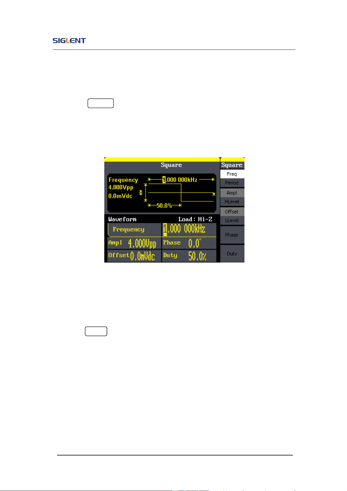
2. Press Square button, and the waveform window displays square
waveform. SDG800 Series Generator can generate square signal with a
frequency from 1μHz to 10MHz and variable duty cycle.
Figure 1- 8 Square Signal Display Interface
As is shown in Figure 1- 8, the default signal parameters are: 1kHz frequency,
4.0Vpp amplitude, 0Vdc offset and 50% duty cycle.
3. Press Ramp button, and the waveform window displays ramp waveform.
SDG800 Series Generator can generate ramp signal with a frequency of
from 1μHz to 300kHz and variable symmetry.

SDG800 User Manual 9
Figure 1- 9 Ramp Signal Display Interface
As is shown in Figure 1- 9, the default signal parameters are: 1kHz frequency,
4.0Vpp amplitude, 0Vdc offset and 50% symmetry.
4. Press Pulse button, and the waveform window displays pulse waveform.
SDG800 Series Generator can generate pulse signal with a frequency
from 500μHz to 5 MHz and variable pulse width and delay.
Figure 1- 10 Pulse Signal Display Interface

SDG800 User Manual 10
As is shown in Figure 1- 10, the default signal parameters are: 1kHz
frequency, 4.0Vpp amplitude, 0Vdc offset, 200μs pulse width.
5. Press Noise button, and the waveform window displays noise waveform.
SDG800 Series Generator can generate noise signal with a band width
up to 10MHz.
Figure 1- 11 Noise Signal Display Interface
As is shown in Figure 1- 11, the default signal parameters are: 128mV stdev
and 0mV Mean.
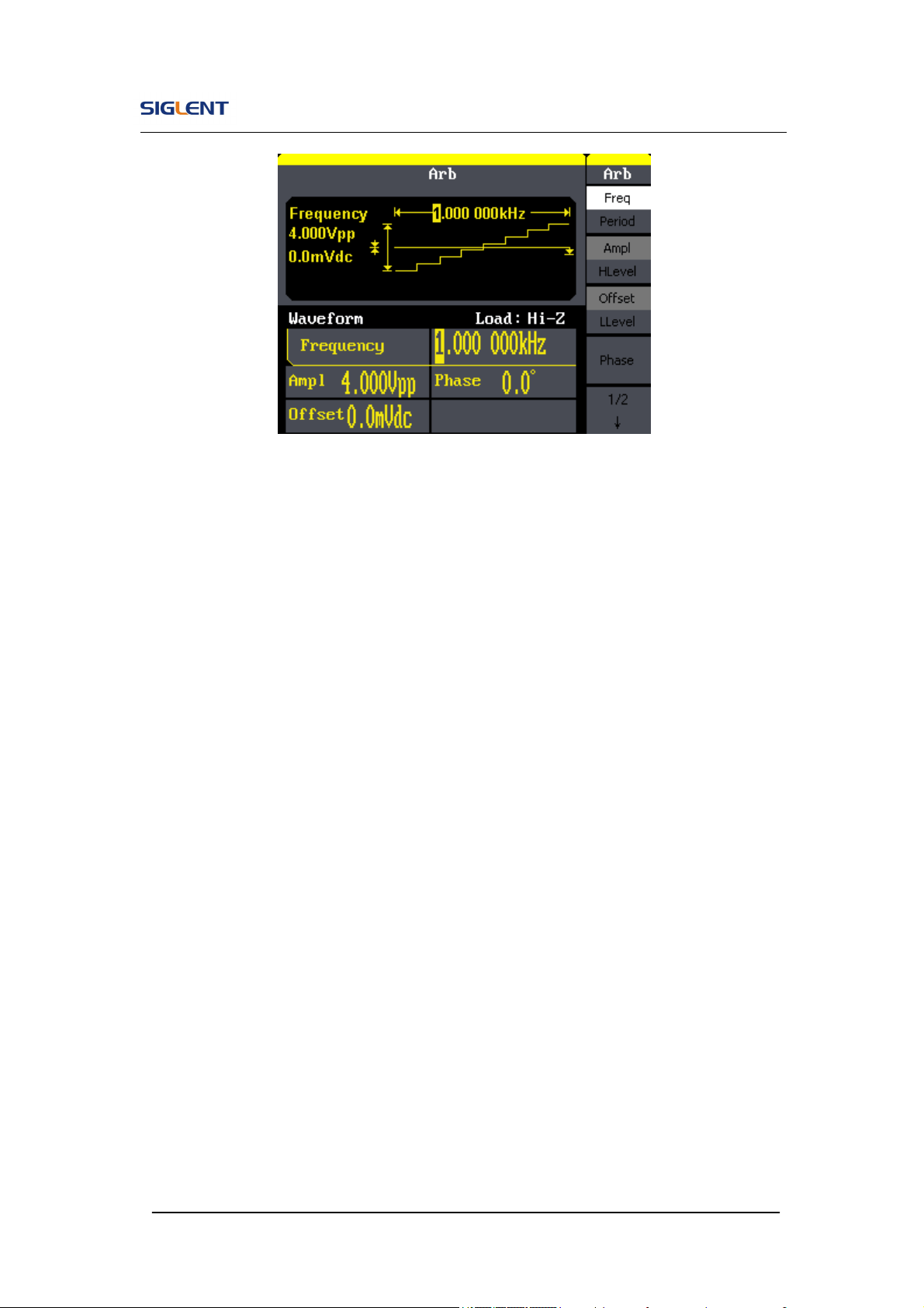
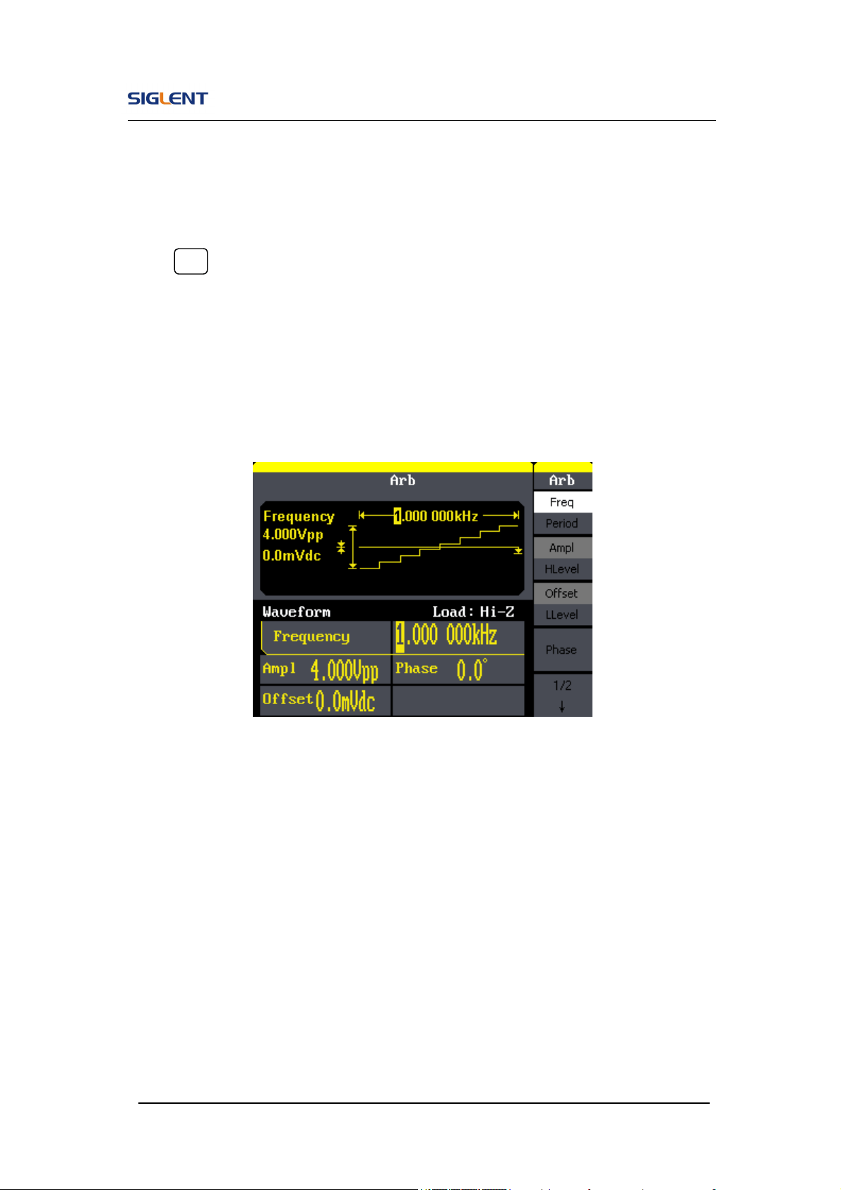
6. Press Arb button, and the waveform window displays arbitrary waveform.
SDG800 Series Generator can generate repeatable arbitrary waveform
signals with at most 16K points and 5MHz frequency.
SDG800 User Manual 11
Figure 1- 12 Arbitrary Waveform Signal Display Interface
As is shown in Figure 1- 12, the default signal parameters are: 1kHz
frequency, 4.0Vpp amplitude and 0mVdc offset.
SDG800 User Manual 12
1.5. To Set Modulate/Sweep/Burst
As shown in Figure 1- 13, there are three buttons on the front panel, which
are used for modulation, sweep and burst settings. The instructions below will
help you familiarize with the setting of these functions.
Figure 1- 13 Modulate/Sweep/Burst Button
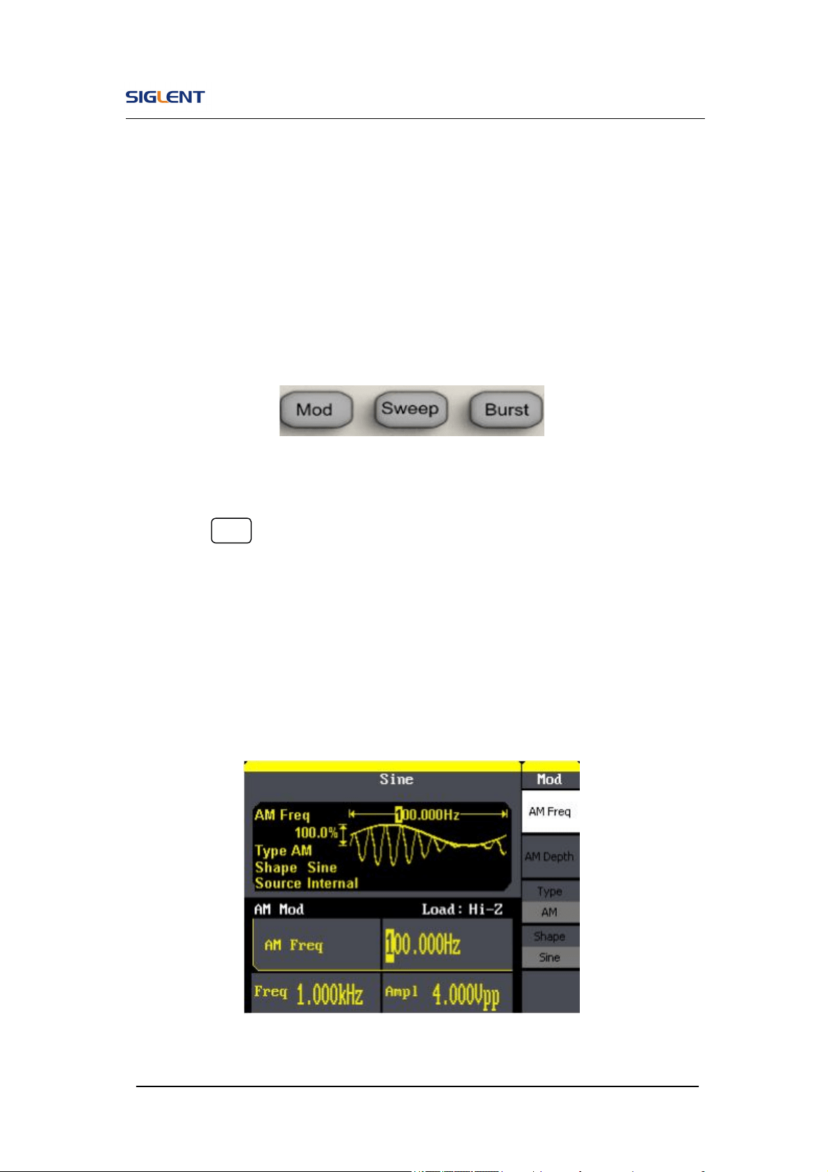
1. Press Mod button, the modulated waveforms will be generated. The
modulated waveform can be changed by modifying the parameters such
as type, internal/external modulation, depth, frequency, waveform, etc.
SDG800 Series can modulate waveform using AM, FM, PM, ASK, FSK,
PWM and DSB-AM. Sine, square, ramp and arbitrary waveforms can be
modulated (pulse, noise and DC can not be modulated).
Figure 1- 14 Modulated Waveform Display Interface
SDG800 User Manual 13
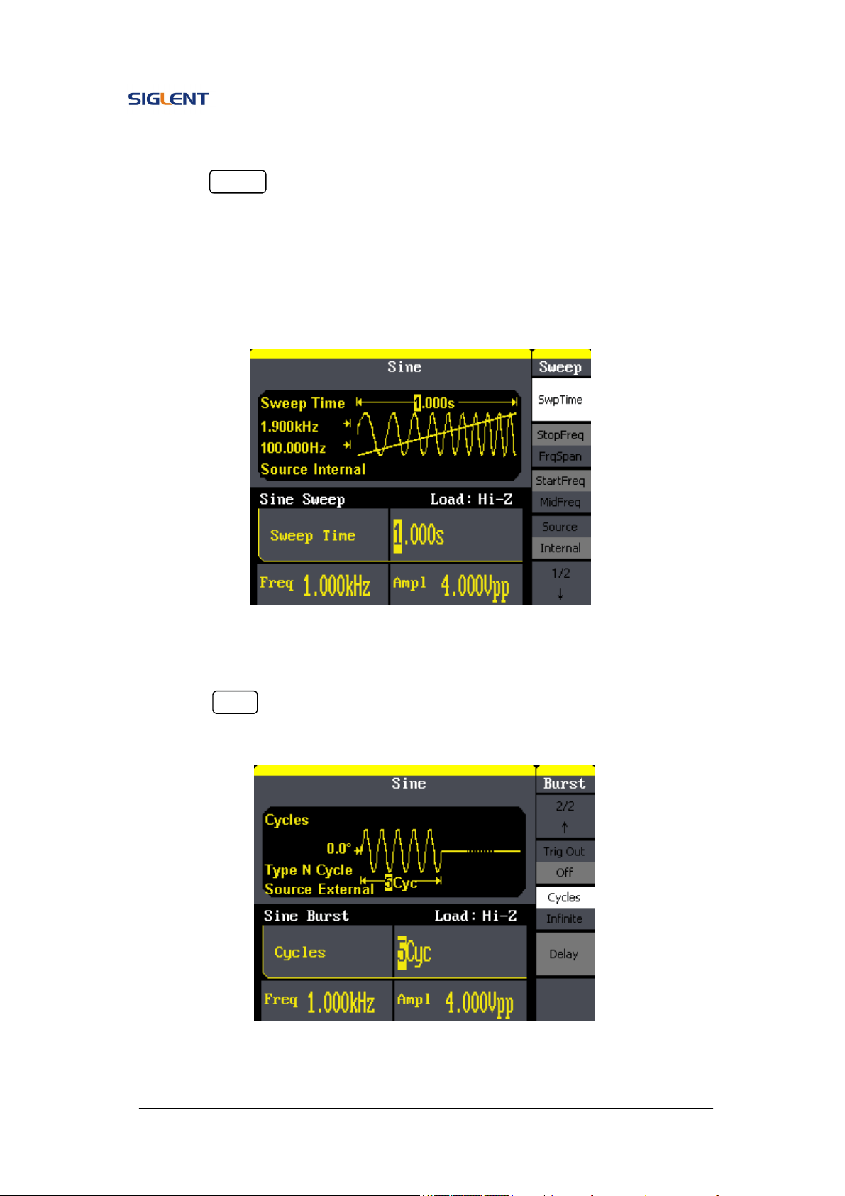
2. Press Sweep button, sine, square, ramp or arbitrary waveform can be
swept (pulse, noise and DC can not be swept).
In the sweep mode, SDG800 Series generate signal with variable
frequencies.
Figure 1- 15 Sweep Waveform Display Interface
3. Press Burst button, burst for sine, square, ramp, pulse or arbitrary
waveform can be generated.
Figure 1- 16 Burst Waveform Display Interface
SDG800 User Manual 14
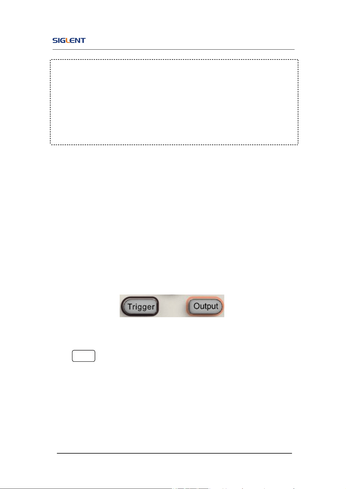
1.6. To Set Output
As is shown in Figure 1- 17, there are two buttons on the right side of the
operation panel, which are used to output/trigger control. The instruction
below will help you familiarize with these functions.
Figure 1- 17 Output Buttons
Press Output button, activate or deactivate the output signal.
Term Explanation
Burst: Output waveforms with set cycle times.
Burst can last for certain times of waveform cycle (N-Cycle Burst) or be
controlled by external gated signals (Gated Burst). Burst applies to all
kinds of waveforms, but noise can only be used in gated burst. Generally it
is called burst function within every signal generator.
SDG800 User Manual 15
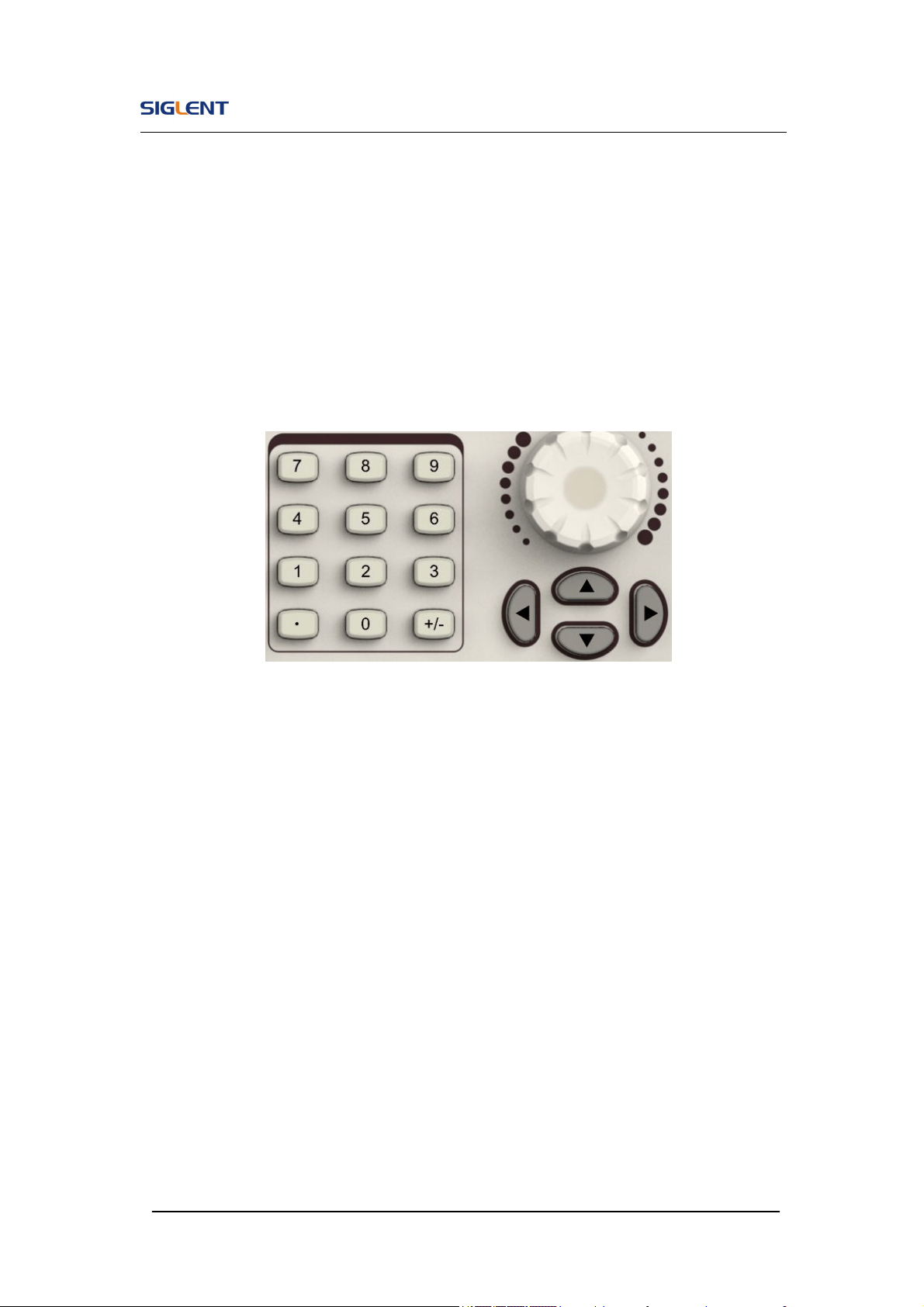
1.7. To Use Digital Input
As is shown in Figure 1- 18, there are three sets of buttons on the operation
panel, which are direction button, the knob and the keypad. The instruction
below will help you familiarize with the digital input function.
Figure 1- 18 Front Panel Digital Input
1. The up and down keys are used to shift parameters and the left and right
keys are used to shift digits.
2. Keypad is used to directly set the parameters value.
3. Knob is used to change a signal digit value whose range is 0~9.
SDG800 User Manual 16
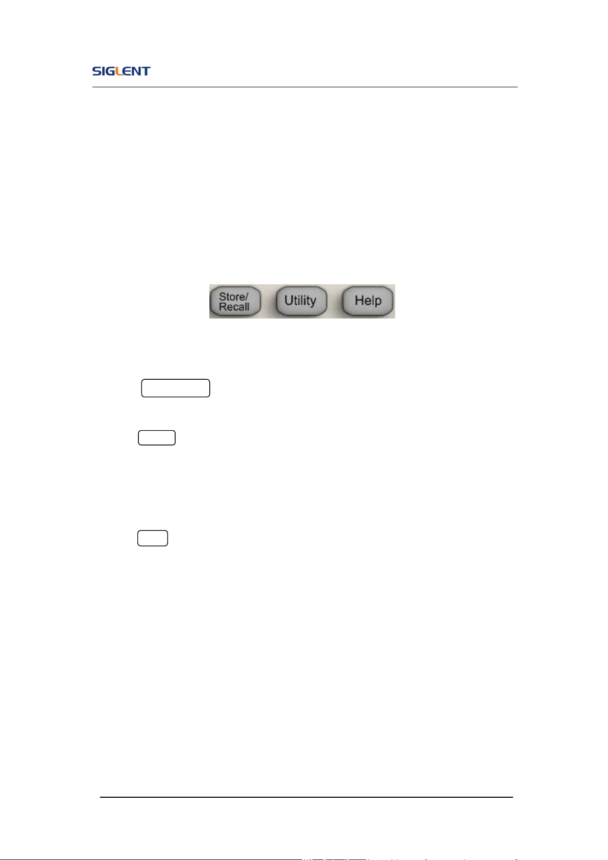
1.8. To Use Store/Utility/Help Function
As is shown in Figure 1- 19, there are three buttons on the operation panel,
which are used to call the store/recall, utility and help function. The instruction
below will help you familiarize with these functions.
Figure 1- 19 Store/Recall Utility and Help Button
1. The Store/Recall button is used to store waveform data and configure
information.
2. The Utility button is used to set the auxiliary system function, change
the output configure parameters, interface setting, system setting
information or perform the instrument self-test and read the calibration
information, etc.
3. The Help button is used to read the help information.
SDG800 User Manual 17
2. Operating Your Generator
Up to now you have got a brief understanding about SDG800 series with the
front/rear panel, every function control area and keys. You should also know
how to set your Function/Arbitrary Waveform Generator for your usage. If you
are not familiar with these operations, you are suggested to read chapter one
‘Getting Started’ again.
This chapter covers the following topics:
Setting Sine Signal
Setting Square Signal
Setting Ramp Signal
Setting Pulse Signal
Setting Noise Signal
Setting Arb Signal
Output Modulated Signal
Output Sweep Signal
Output Burst Signal
Store/Recall
Utility Setting
Help System
You are suggested to read this chapter carefully so as to understand
SDG800 Series Generator’s versatile waveform setting functions and
more operation methods.
SDG800 User Manual 18
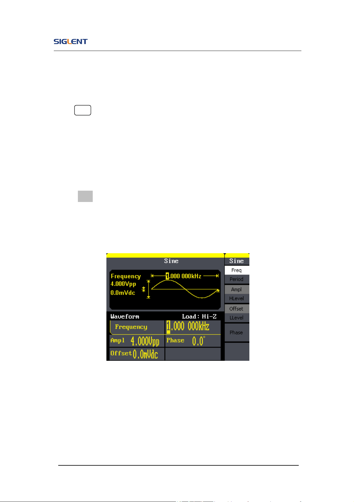
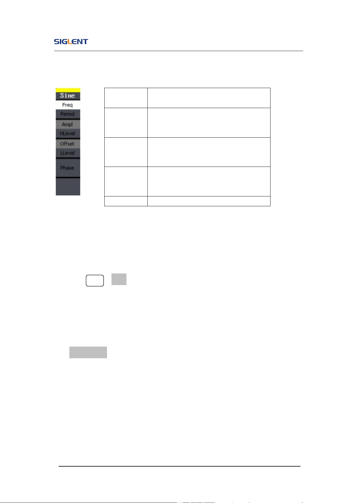
2.1. To Set Sine Signals
Press Sine button to call the sine operation. The sine waveform parameters
are set by using the sine operation menu.
The parameters of sine waveforms are: frequency/period, amplitude/high
level, offset/low level and phase. Different sine signals are generated by
setting these parameters. As is shown in Figure 2- 1, in the soft key menu,
select Freq. Cursor is located in the frequency parameter area in the
parameter display window, and users can set the frequency value here.
Figure 2- 1 Sine Parameter Display Interface
SDG800 User Manual 19
Figure 2- 2 Table2- 1 Menu Explanations of Sine Waveform
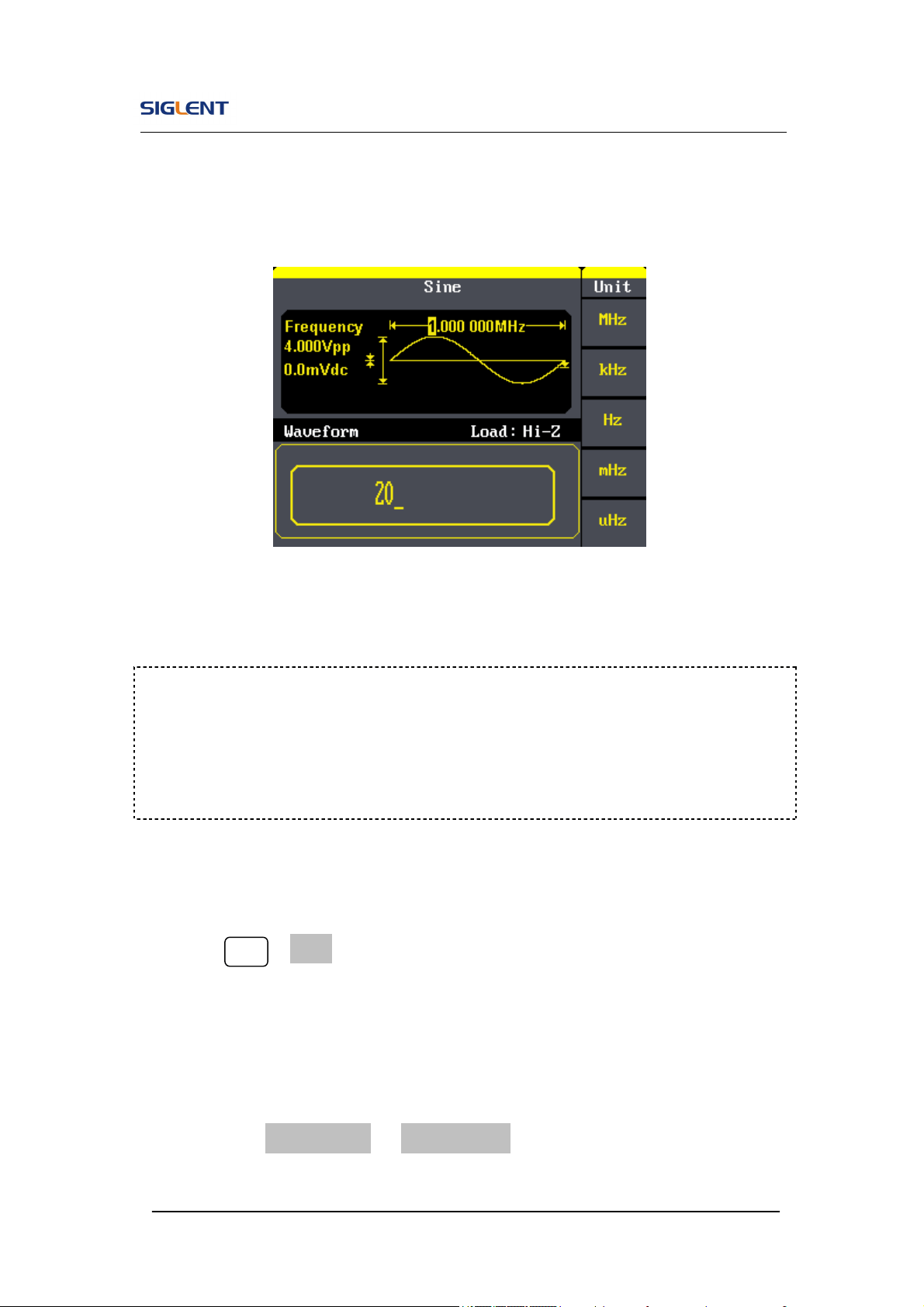
To Set the Output Frequency/Period
1. Press Sine →Freq, to set the frequency parameter.
The frequency shown on the screen when the instrument is powered is
the default value or the set value beforehand. When setting the function,
if the current value is valid for the new waveform, it will be used
sequentially. If you want to set the period for the waveform, press
Freq/Period button again, to switch to the period parameter (the current
operation is displayed in inverse color).
2. Input the desired frequency.
Use the keypad to input the parameter value directly, and press the
corresponding button to select the parameter unit. Or you can use the
direction button to select the digit you want to edit, and then use the knob
Function
menu
Explanations
Freq/
Period
Set the signal frequency or period;
The current parameter will be switched at
a second press.
Ampl/
HLevel
Set the signal amplitude or high level;
The current parameter will be switched at
a second press.
Offset/
LLevel
Set the signal offset or low level;
The current parameter will be switched at
a second press.
Phase Set the phase of the signal;
SDG800 User Manual 20
to change its value.
Figure 2- 3 Setting the Frequency
To Set the Output Amplitude
1. Press Sine →Ampl, to set the amplitude.
The amplitude shown on the screen when the instrument is powered is
the default value or the set value beforehand. When changing the
function, if the current value is valid for the new waveform, it will be used
sequentially. If you want to set the waveform by high level or low level,
press the Ampl/HLevel or Offset/LLevel button again, to switch into the
high level or low level parameter (the current operation is displayed in
Instruction:
When using the keypad to enter the digit, you can use the left direction button
to move the cursor backward and delete or change the value of the previous
digit.

SDG800 User Manual 21
inverse color).
2. Input the desired Amplitude
Use the keypad or the knob to input the desired value, choose the unit,
and press the corresponding button.
Figure 2- 4 Setting the Amplitude
To Set the Output Offset
1. Press Sine →Offset, to set the offset.
The offset shown on the screen when the instrument is powered is the
default value or the set value beforehand. When changing the function, if
the current value is valid for the new waveform, it will be used
sequentially.
2. Input the desired Offset
Use the keypad or the knob to input the desired value, choose the unit,
and press the corresponding button.
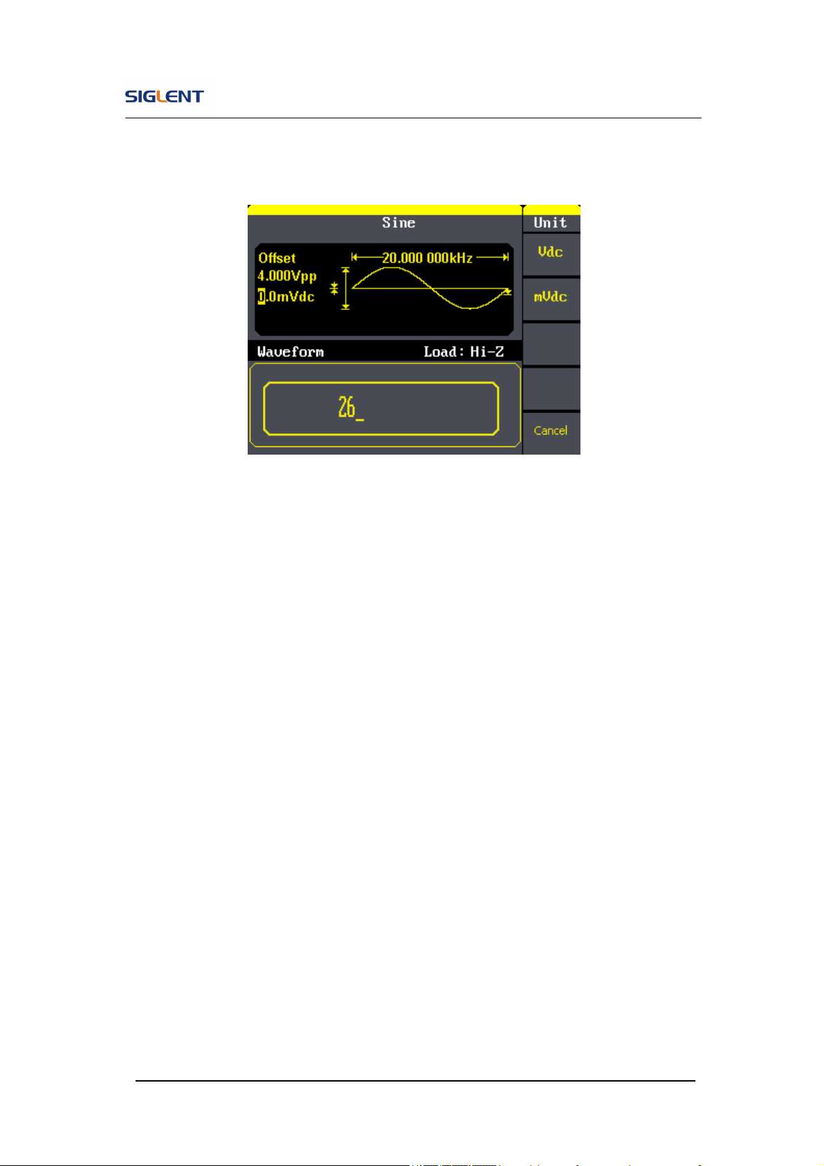
SDG800 User Manual 22
Figure 2- 5 Setting the Offset
SDG800 User Manual 23
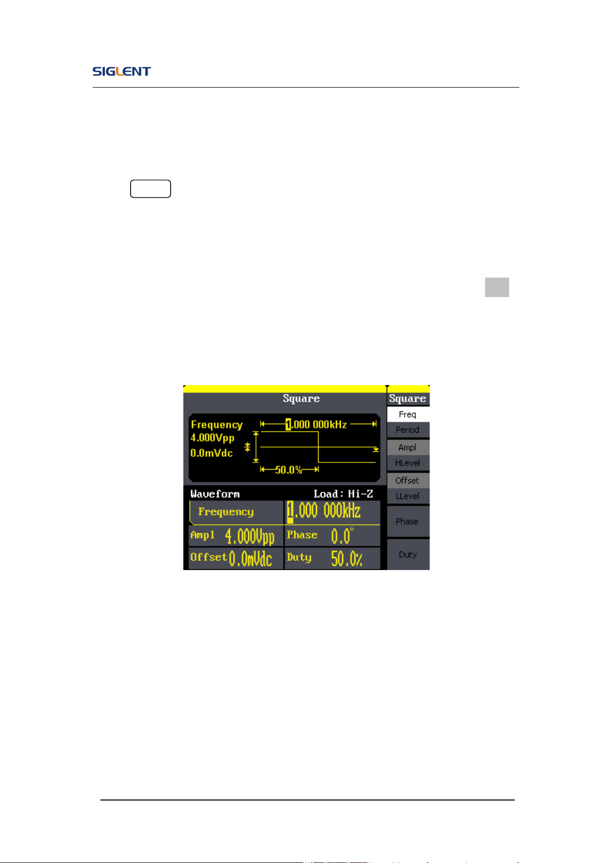
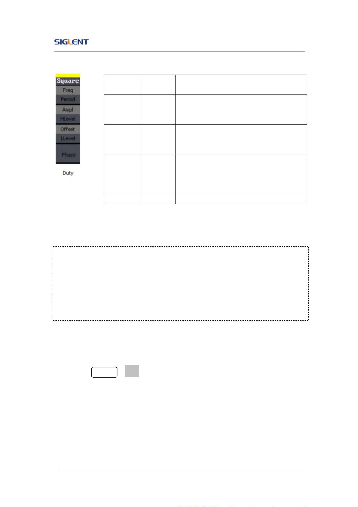
2.2. To Set Square Signals
Press Square button to call the Square operation. The square waveform
parameters are set by using the Square operation menu.
The parameters of Square waveforms are: frequency/period, amplitude/high
level, offset/low level, phase and duty. As is shown in Figure 2- 6, select Duty.
Cursor is located in the duty parameter area in the parameter display window,
and users can set the duty value here.
Figure 2- 6 Square Parameter Display Interface
SDG800 User Manual 24
Figure 2- 7 Table2- 2 Menu Explanations of Square Waveform
Term Explanation:
Duty Cycle: The percentage that the high level takes up the whole period.
Please Note : for the Frequency Duty Cycle Value
Below 10MHz: 20% to 80%
To Set the Duty Cycle
1. Press Square →Duty, to set the duty cycle.
The duty cycle shown on the screen when the instrument is powered is
the default value or the set value beforehand. When changing the
function, if the current value is valid for the new waveform, it will be used
sequentially.
Function
Menu
Settings
Explanation
Freq/
Period
Set the signal frequency or period;
The current parameter will be switched at a
second press.
Ampl/
HLevel
Set the signal amplitude or high level;
The current parameter will be switched at a
second press.
Offset/
LLevel
Set the signal offset or low level;
The current parameter will be switched at a
second press.
Phase Set the phase of the signal;
Duty Set the duty cycle for square waveform.

SDG800 User Manual 25
2. Input the desired Duty Cycle
Use the keypad or the knob to input the desired value, choose the unit,
and press the corresponding button. The generator will change the
waveform immediately.
Figure 2- 8 Setting the Duty Cycle

SDG800 User Manual 26
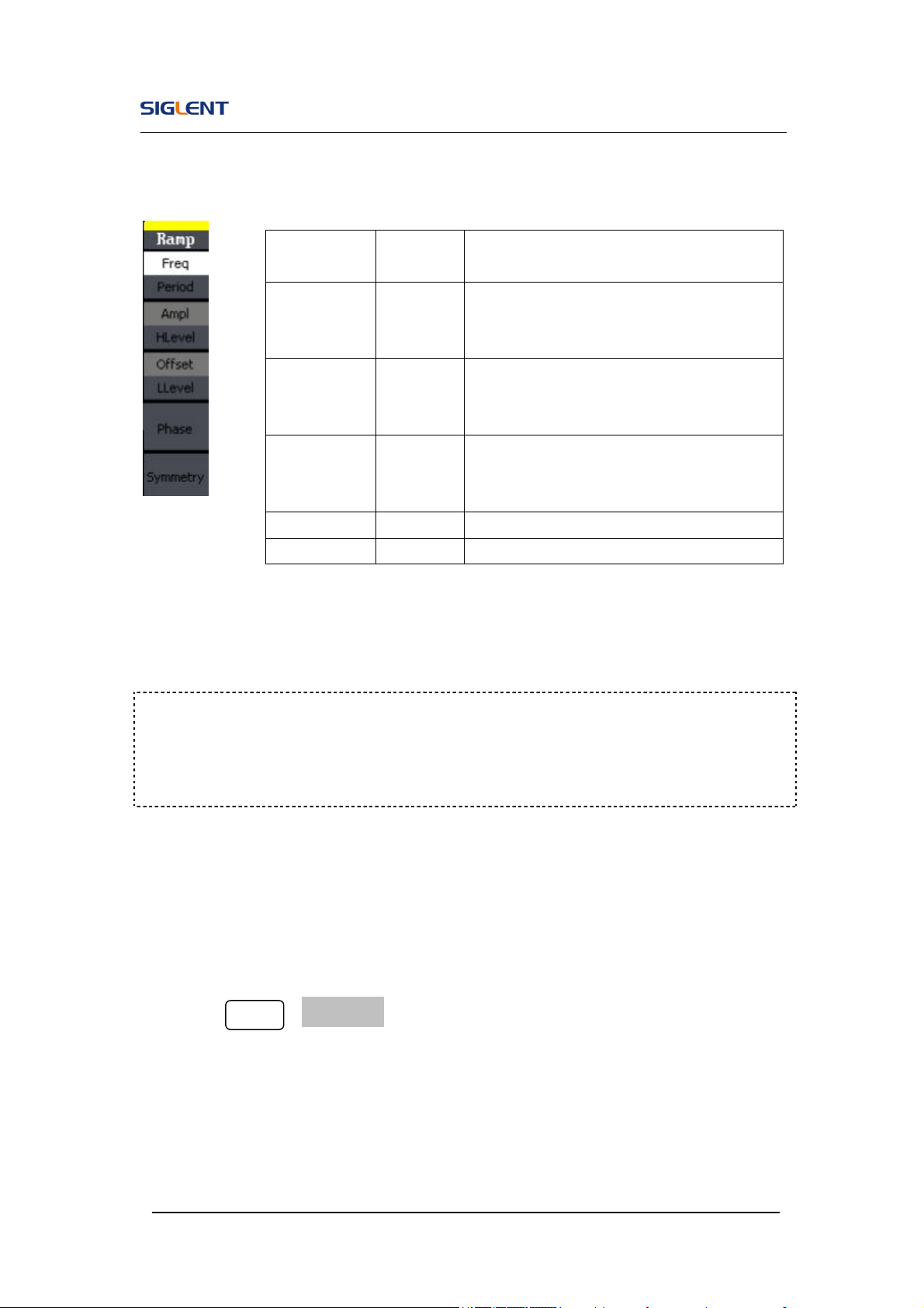
2.3. To Set Ramp Signals
Press Ramp button to call the ramp operation. The ramp waveform
parameters are set by using the ramp operation menu.
The parameters for ramp waveforms are: frequency/ period, amplitude/ high
level offset/ low level, phase and symmetry. As is shown in Figure 2- 9, in the
soft key menu, select Symmetry. Cursor is located in the symmetry parameter
area in the parameter display window, and users can set the symmetry value
here.
Figure 2- 9 Ramp Parameter Display Interface
SDG800 User Manual 27
Figure 2- 10 Table2- 3 Menu Explanations of Ramp Waveform
To Set the Symmetry
1. Press Ramp →Symmetry, to set the symmetry.
The symmetry shown on the screen when the instrument is powered is
the default value or the set value beforehand. When changing the
function, if the current value is valid for the new waveform, it will be used
sequentially.
Function
Menu
Settings
Explanation
Freq/
Period
Set the signal frequency or period;
The current parameter will be switched at
a second press.
Ampl/
HLevel
Set the signal amplitude or high level;
The current parameter will be switched at
a second press.
Offset/
LLevel
Set the signal offset or low level;
The current parameter will be switched at
a second press.
Phase Set the phase of the signal;
Symmetry Set the symmetry for ramp waveform.
Term Explanation:
Symmetry: The percentage that the rising period takes up the whole Period.
Input Range: 0~100%.
SDG800 User Manual 28
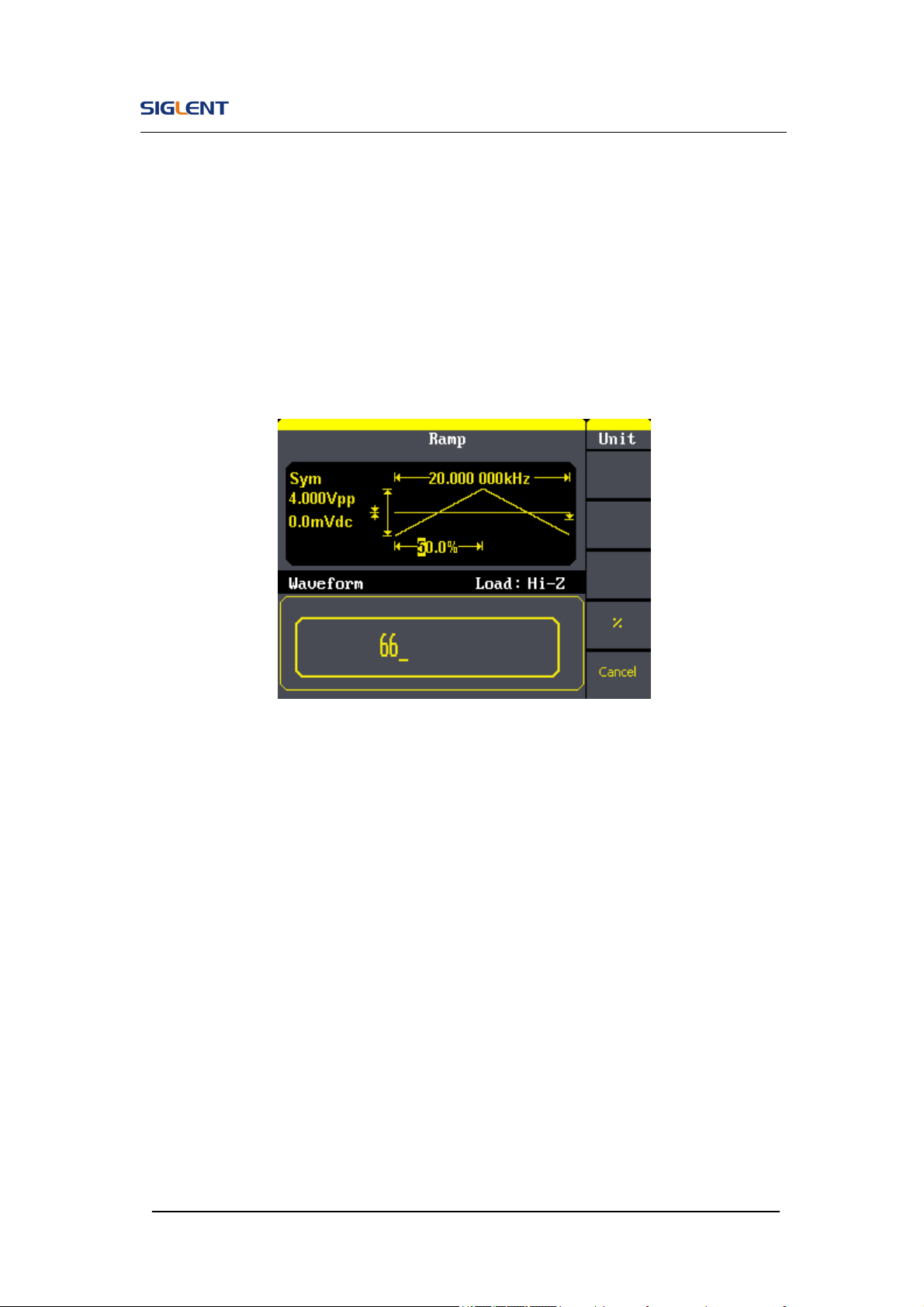
2. Input the desired Symmetry
Use the keypad or the knob to input the desired value, choose the unit,
and press the corresponding button. The generator will change the
waveform immediately.
Figure 2- 11 Setting the Symmetry
SDG800 User Manual 29
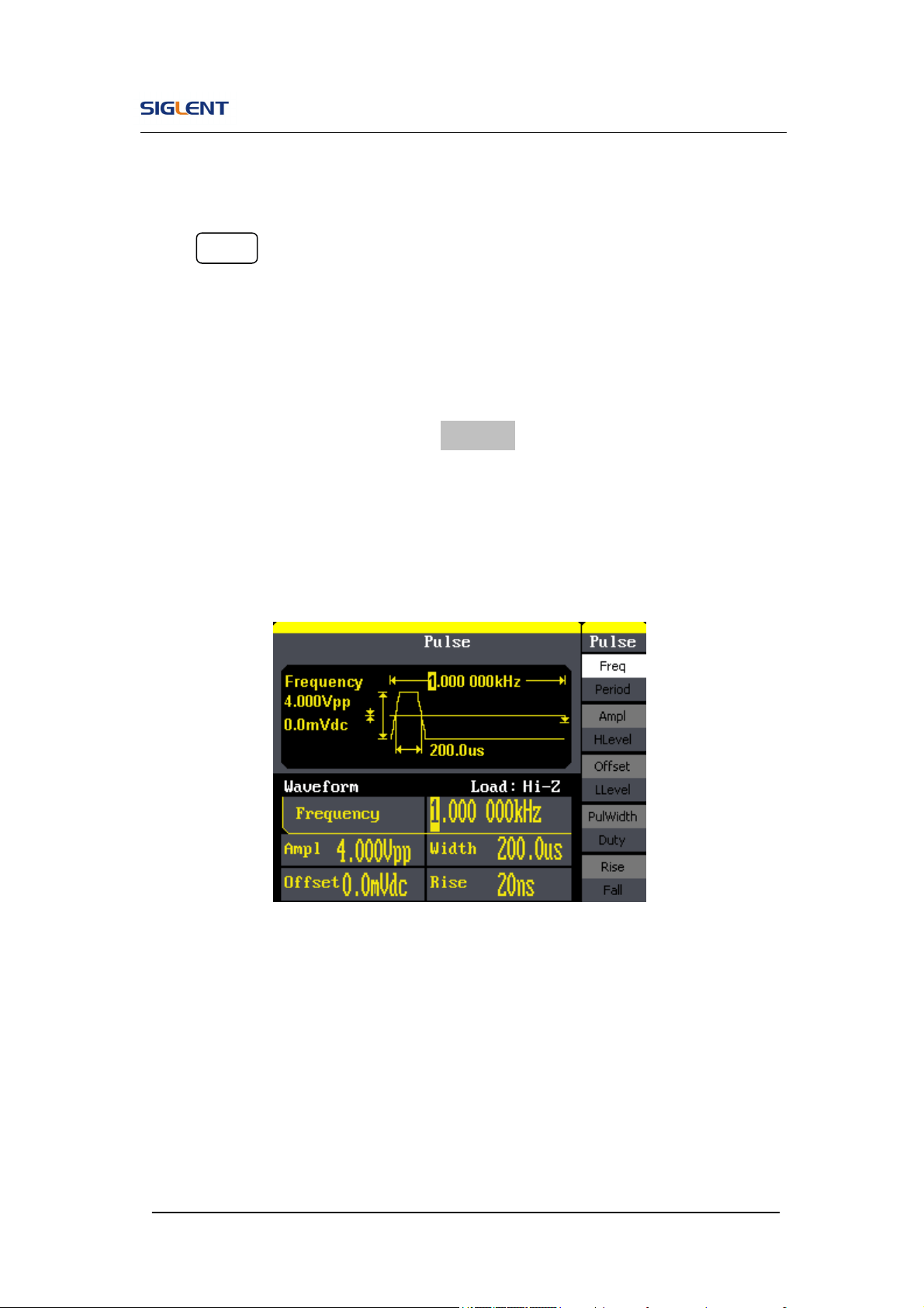
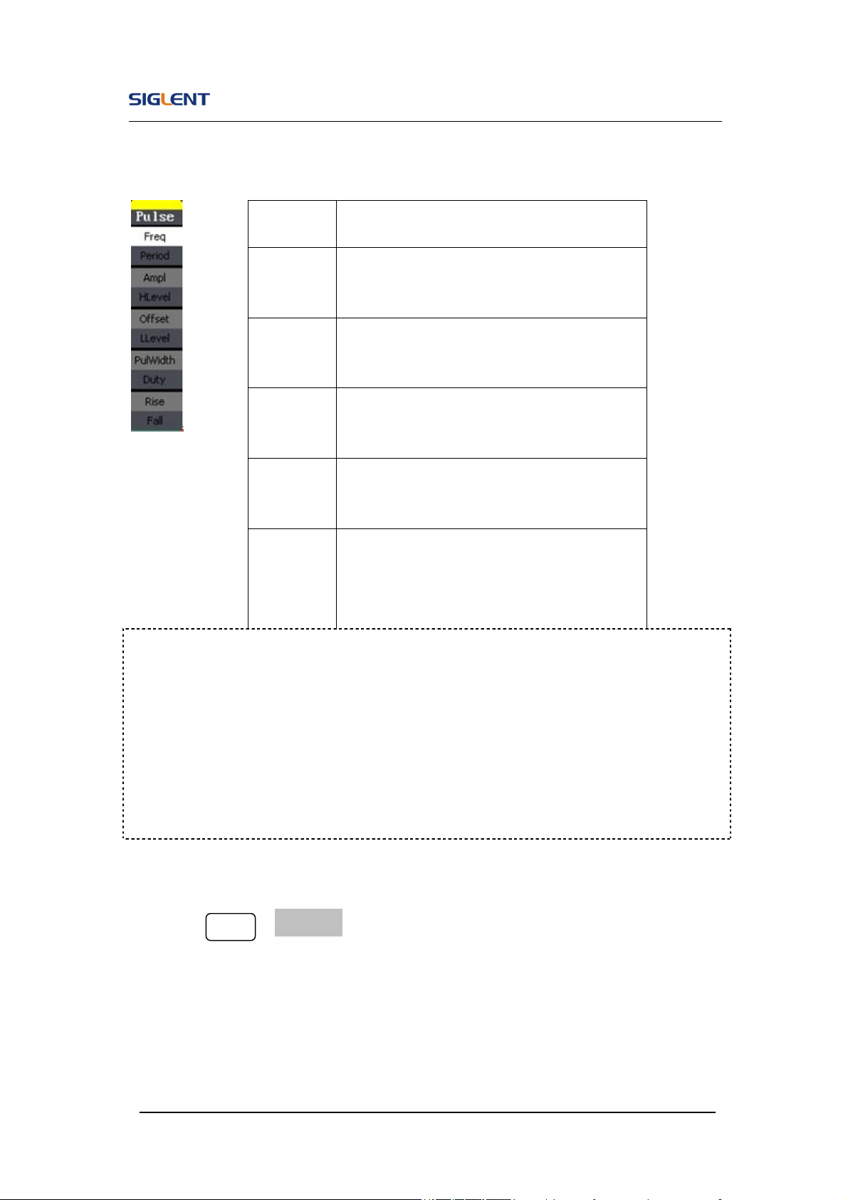
2.4. To Set Pulse Signals
Press Pulse button to call the pulse operation. The pulse waveform
parameters are set by using the pulse operation menu.
The parameters for pulse waveforms are: frequency/period, amplitude/high
level, offset/low level, pulse width/Duty and Rise/Fall. As is shown in Figure
2- 12, in the soft key menu, select PulWidth. Cursor is located in the pulse
width parameter area in the parameter display window, and users can set the
pulse width value here.
Figure 2- 12 Pulse Parameter Display Interface
SDG800 User Manual 30
Figure 2- 13 Table 2- 4 Menu Explanations of Pulse Waveform
To Set the Pulse Width
1. Press Pulse →PulWidth, to set the pulse width.
The pulse width shown on the screen when the instrument is powered is
the default value or the set value beforehand. When changing the
function, if the current value is valid for the new waveform, it will be used
sequentially.
Function
Menu
Explanation
Freq/
Period
Set the signal frequency or period;
The current parameter will be switched at a
second press.
Ampl/
HLevel
Set the signal amplitude or high level;
The current parameter will be switched at a
second press.
Offset/
LLevel
Set the signal offset or low level;
The current parameter will be switched at a
second press.
PulWidth
/Duty
Set the signal pulse width or duty;
The current parameter will be switched at a
second press.
Rise /
Fall
Setting the rising edge for pulse waveform.
Setting the falling edge for pulse waveform
Term Explanation:
Pulse Width:
Positive Pulse Width: the time span between thresholds of 50% of the rising
edge amplitude to the next 50% of the falling edge amplitude;
Negative Pulse Width: the time span between thresholds of 50% of the falling
edge amplitude to the next 50% of the rising edge amplitude.
SDG800 User Manual 31
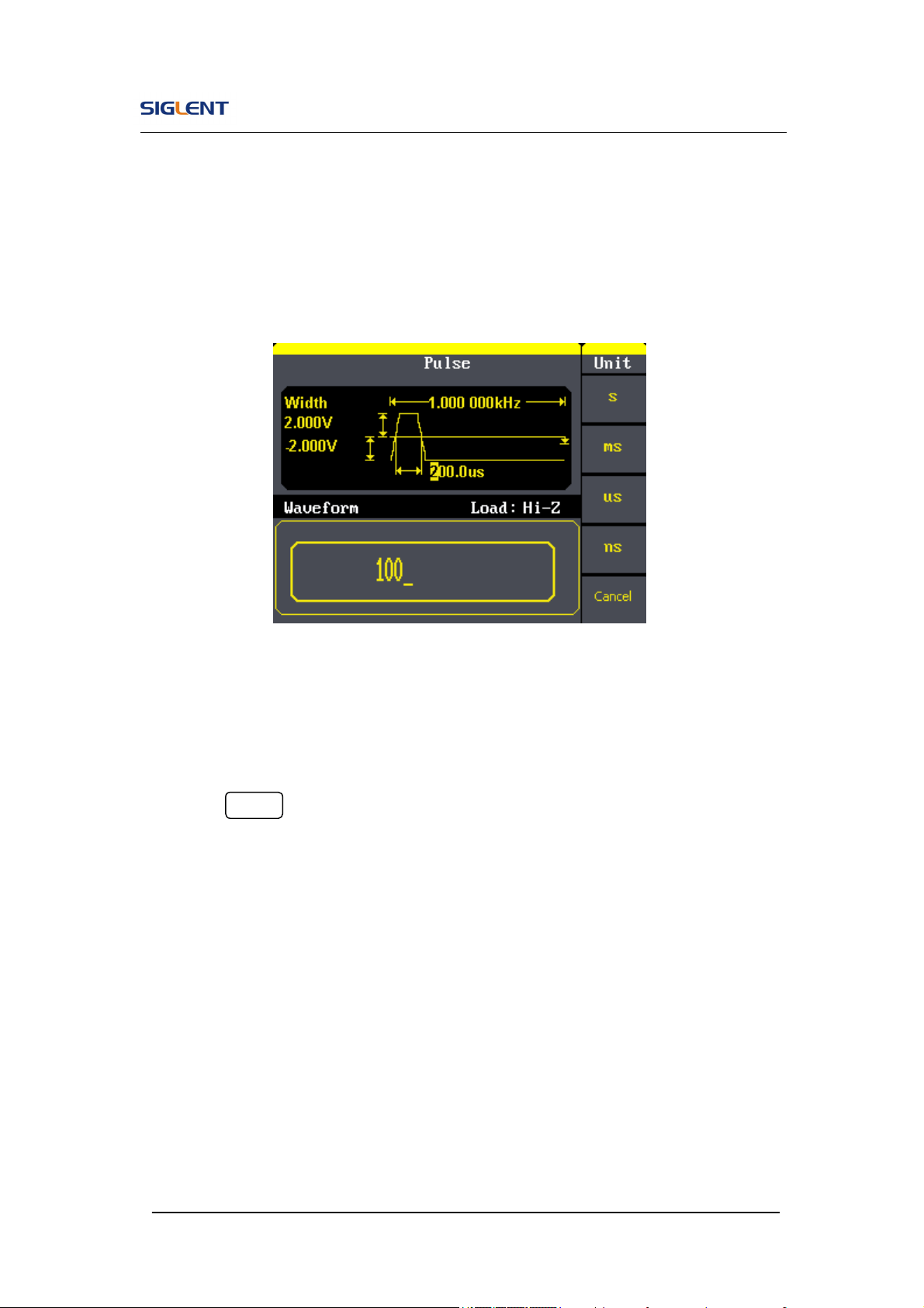
2. Input the desired Pulse Width
Use the keypad or the knob to input the desired value, choose the unit,
and press the corresponding button. The Generator will change the
waveform immediately.
Figure 2- 14 Setting the Pulse Width
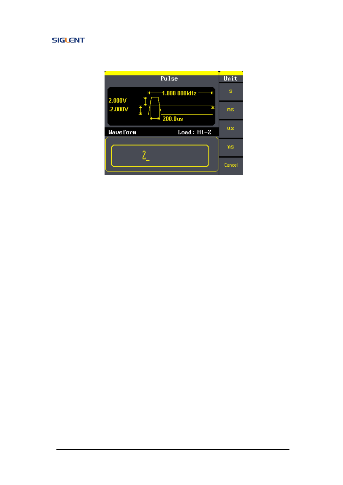
To Set the Rising Edge
1. Press Pulse →Rise, to set the Rise edge.
The rising edge shown on the screen when the instrument is powered is
the default value or the set value beforehand. When changing the
function, if the current value is valid for the new waveform, it will be used
sequentially.
2. Input the desired rising edge
Use the keypad or the knob to input the desired value, choose the unit,
and press the corresponding button. The generator will change the
waveform immediately.
SDG800 User Manual 32
Figure 2- 15 Setting the Rise edge
SDG800 User Manual 33
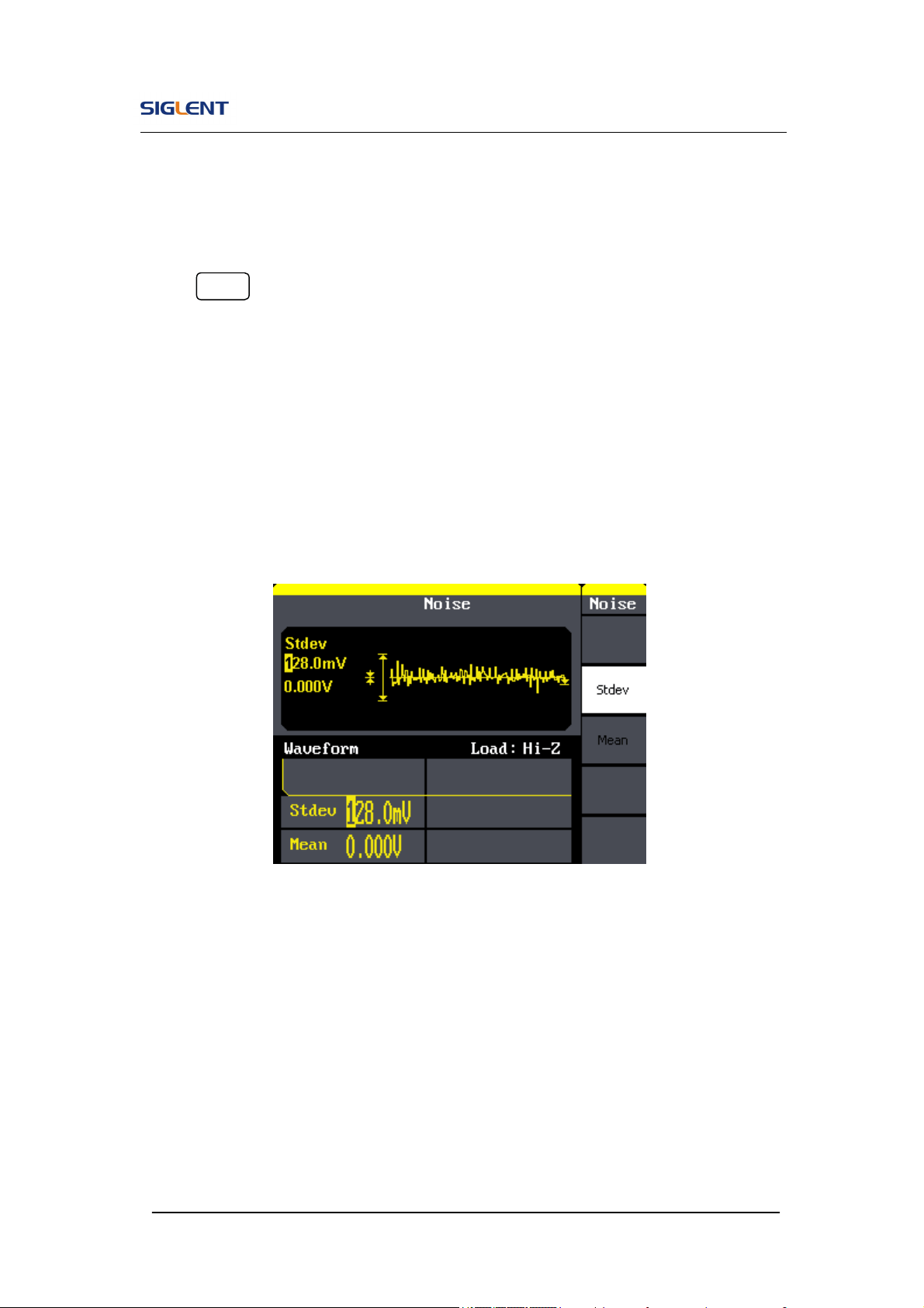
2.5. To Set Noise Signals
Press Noise button to call the Gaussian White noise operation. The noise
waveform parameters are set by using the noise operation menu.
The parameters for noise waveforms are: Stdev and mean. As is shown in
Figure 2- 16, in the soft key menu, select Stdev, Cursor is located in the Stdev
parameter area in the parameter display window, and users can set the Stdev
value here. Noise is non-regulated signal which has no frequency or period.
Figure 2- 16 Noise Parameter Display Interface

SDG800 User Manual 34
Figure 2- 17 Table 2- 5 Menu Explanations of Noise Waveform
Function
Menu
Settings
Explanation
Stdev Set the signal standard deviation
Mean Set the signal mean
SDG800 User Manual 35
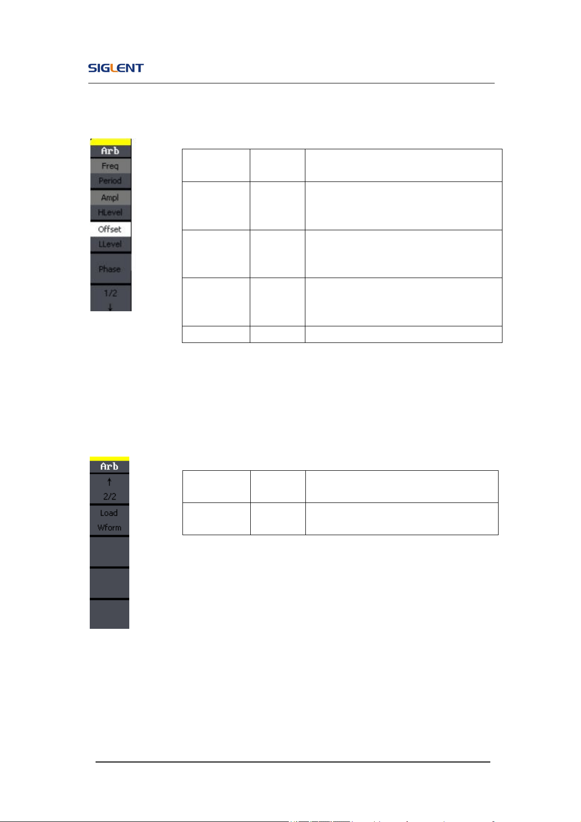
2.6. To Set Arbitrary Signals
Press Arb button to call the Arb operation. The Arb waveform parameters are
set by using the Arb operation menu.
The Arb signal consists of two types: the system built-in waveform and the
user-definable waveform. The parameters for Arb waveforms are:
frequency/period, amplitude/high level, offset/ low level and phase.
Figure 2- 18 Arb Parameter Display Interface
SDG800 User Manual 36
Figure 2- 19 Table 2- 6 Menu Explanations of Arb Waveform (Page 1/2)
Figure 2- 20 Table 2- 7 Menu Explanations of Arb Waveform (Page 2/2)
Function
Menu
Settings
Explanation
Freq/
Period
Set the signal frequency or period;
The current parameter will be switched at
a second press.
Ampl/
HLevel
Set the signal amplitude or high level;
The current parameter will be switched at
a second press.
Offset/
LLevel
Set the signal offset or low level;
The current parameter will be switched at
a second press.
Phase Set the phase of the signal;
Function
Menu
Settings
Explanation
Load Wform
Select the built-in arbitrary signal as
output.
SDG800 User Manual 37
To select the built-in Arbitrary Waveform
There are forty-eight built-in Arbitrary Waveforms and user-definable Arbitrary
Waveforms inside the Generator. To select one of them, follow the
instructions below:
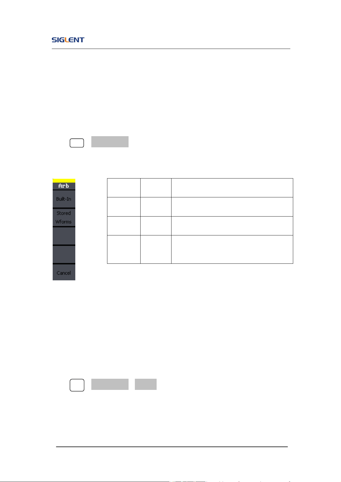
Press Arb →Load Wform, to enter the interface below.
Figure 2- 21 Table 2- 8 Menu Explanations of Built-in Arbitrary Waveform
1. To Select the Built-in Waveform
Press Arb →Load Wform->Built-In, and enter the following interface.
As is shown in Figure 2- 22, there are five kinds of arbitrary waveform.
Function
Menu
Settings
Explanation
Built-In
Select one of the 46 types built-in arbitrary
waveforms.
Stored
Wforms
Select one of arbitrary waveforms stored in
the non-volatile memory.
Cancel
Cancel the current operation, and return to
the upper menu (the followings are the
same and will not be explained).
SDG800 User Manual 38
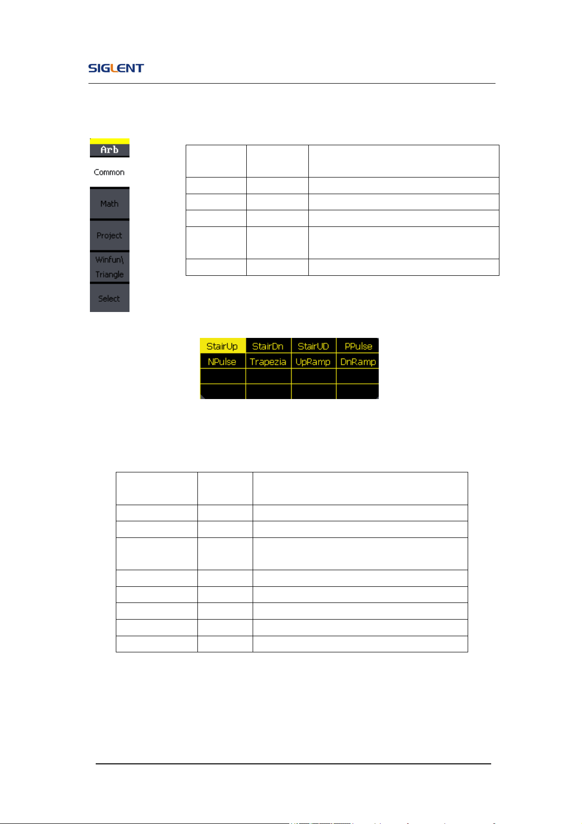
Figure 2- 22 Table 2- 9 Menu Explanations of Built-In Arbitrary Waveform
Figure 2- 23 Common Built-In Arbitrary Waveform interface
Table 2- 10 Menu Explanations of Common Built-In Arbitrary Waveform
Function
Menu
Settings Explanation
Common Select common waveform.
Math Select math waveform.
Project Select project waveform.
Winfun/
Triangle
Select windows function
/triangle waveform.
Select Validate the built-in waveform.
Function
Menu
Settings
Explanation
StairUp Select the built-in stair up waveform.
StairDn Select the built-in stair down waveform.
StairUD
Select the built-in stair up and down
waveform.
PPulse Select the built-in positive pulse waveform.
NPulse Select the built-in negative pulse waveform.
Trapezia Select the built-in trapezoid waveform
UpRamp Select the built-in up ramp waveform.
DnRamp Select the built-in down ramp waveform.
SDG800 User Manual 39
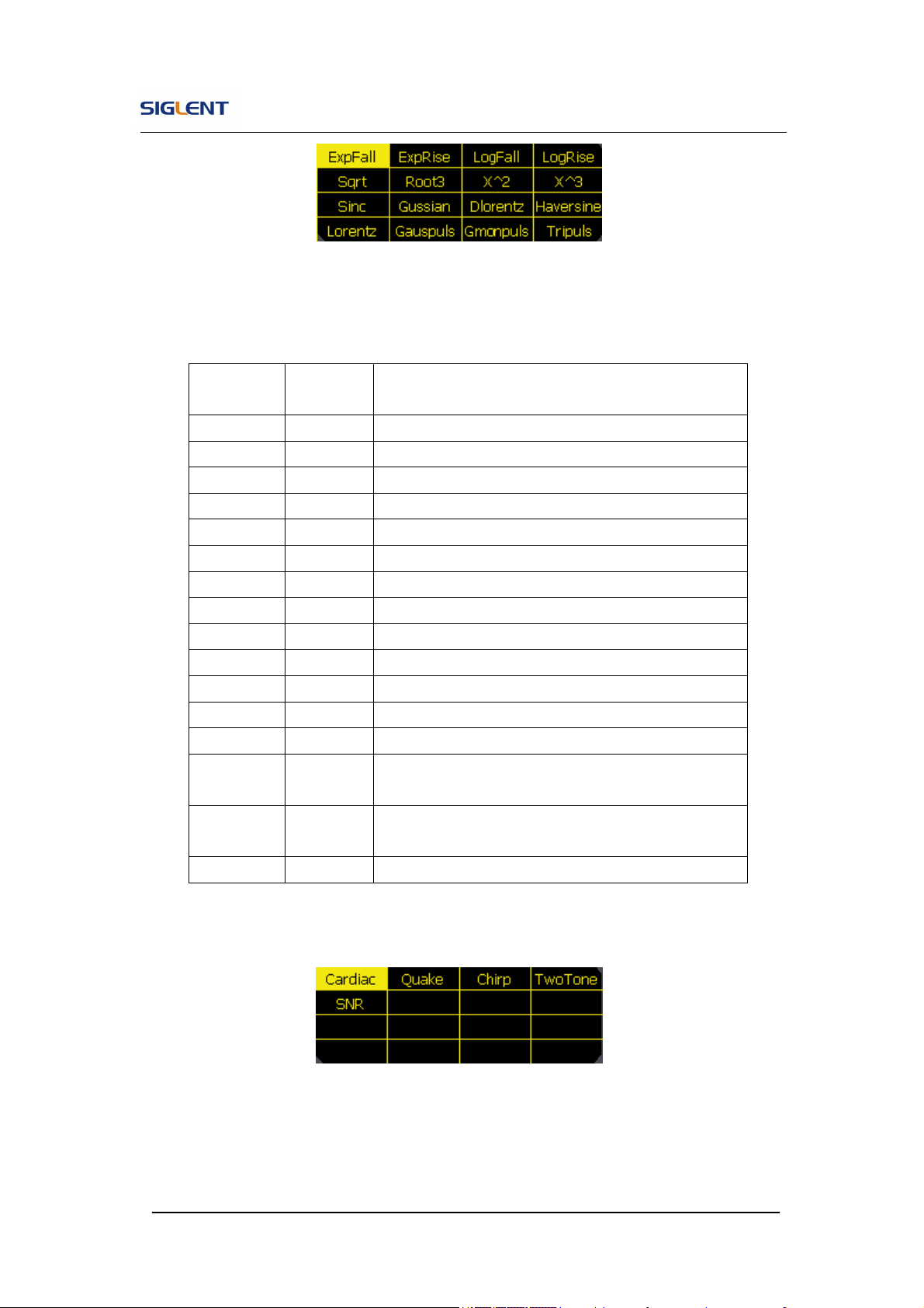
Figure 2- 24 Math Built-In Arbitrary Waveform Interface
Table 2- 11 Menu Explanations of Math Built-in Arbitrary Waveform
Figure 2- 25 Project Built-In Arbitrary Waveform interface
Function
Menu
Settings
Explanation
ExpFall Select the built-in exponential fall waveform.
ExpRise Select he built-in exponential rise waveform.
LogFall Select the built-in logarithmic fall waveform.
LogRise Select the built-in logarithmic rise waveform.
Sqrt Select the built-in square root waveform.
Root3 Select the built-in Root3 waveform.
X^2 Select the built-in X^2 waveform.
X^3 Select the built-in X^3 waveform.
Sinc
Select the built-in sinc waveform; Sinc=sin(x)/x.
Gaussian
Select the built-in gaussian waveform.
Dlorentz Select the built-in D-lorentz waveform.
Haversin Select the built-in haversine waveform.
Lorentz Select the built-in lorentz Waveform.
Gauspuls
Select the built-in gaussian-modulated sinusoidal
pulse waveform.
Gmonpuls
Select the built-in Gaussian monopulse
waveform.
Tripuls Select the built-in triangle pulse waveform.
SDG800 User Manual 40
Table 2- 12 Menu Explanations of Project Built-in Arbitrary Waveform
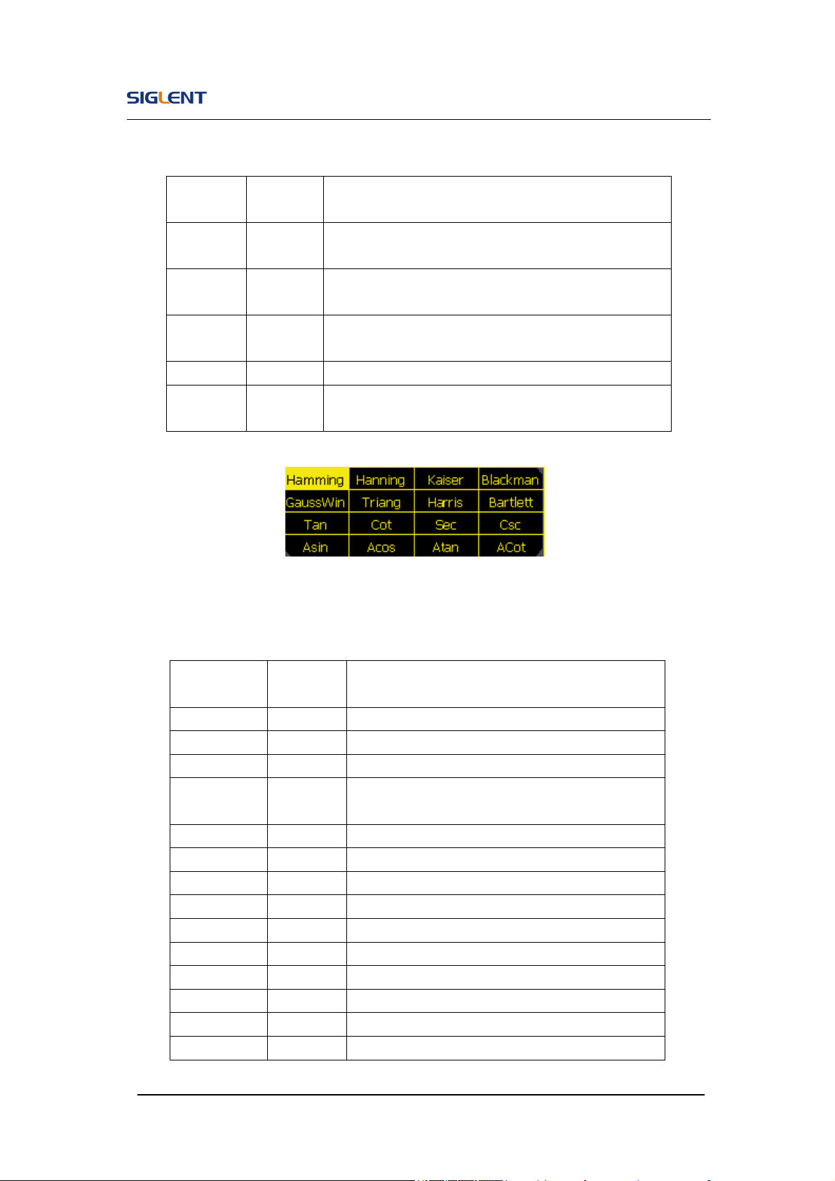
Figure 2- 26 Winfun/Triangle Built-In Arbitrary Waveform interface
Table 2- 13 Menu Explanations of Winfun/Triangle Built-in Arbitrary Waveform
Function
Menu
Settings
Explanation
Cardiac
Select the built-in electrocardiogram (ECG) signal
waveform.
Quake
Select the built-in loma prieta earthquake
waveform.
Chirp
Select the built-in swept-frequency cosine
waveform.
TwoTone
Select the built-in two tone signal waveform.
SNR
Select the built-in sin wave with white noise
waveform.
Function
Menu
Settings
Explanation
Hamming Select the built-in hamming window waveform.
Hanning Select the built-in hanning window waveform.
Kaiser Select the built-in kaiser window waveform.
Blackman
Select the built-in blackman windows
waveform.
Gaussian Select the built-in gaussian window waveform.
Triangle Select the built-in triangle window waveform.
Hairs Select the built-in hairs window waveform.
Bartlett Select the built-in bartlett window waveform.
Tan Select the built-in tangent waveform.
Cot Select the built-in cotangent waveform.
Sec Select the built-in secant waveform.
Csc Select the built-in cosecant waveform
Asin Select the built-in inverse sine waveform.
Acos Select the built-in inverse cosine waveform.
SDG800 User Manual 41
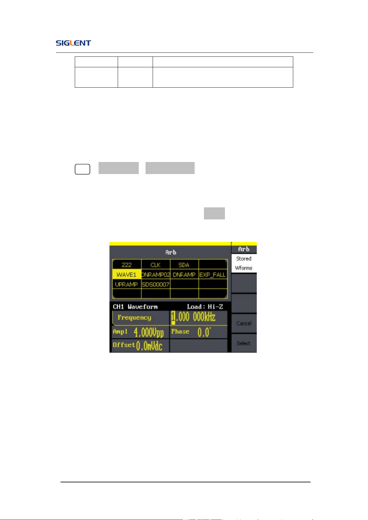
2. To Select the Stored Waveform
Press Arb →Load Wform->Stored Wforms, and enter the following interface.
As is shown in Figure 2- 27, use the direction keys or knob to choose the
corresponding arbitrary waveform and press Select.
Figure 2- 27 Stored Wform Display Interface
Atan Select the built-in tangent waveform.
Acot
Select the built-in inverse cotangent
waveform.
SDG800 User Manual 42
2.7. To Generate the Modulated Waveform
Use the Mod button to generate modulated waveform.SDG800 Series can
generate AM, FM, ASK, FSK, PM, PWM and DSB-AM modulated waveforms.
Modulating parameters vary with the types of the modulation. In AM, users
can set the depth, modulating frequency, modulating waveform and carrier
waveform; In FM, users can set themodulating frequency, frequency
deviation, modulating waveform and carrier waveform; In ASK, users can set
the Key Freq and carrier waveform; In FSK, users can set the key frequency,
Hop Freq and carrier waveform; In PM, users can set the phase deviation,
modulating frequency, modulating waveform and carrier waveform.
We will cover how to set these parameters in details according to the
modulation types.
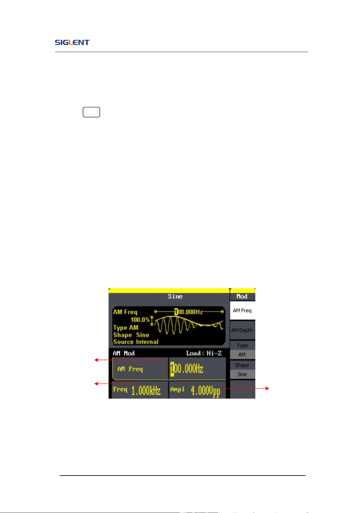
Figure 2- 28 Display Interface of Modulated Waveform Parameter
Carrier
Frequency
Modulating
Frequency
Carrier
Amplitude
SDG800 User Manual 43
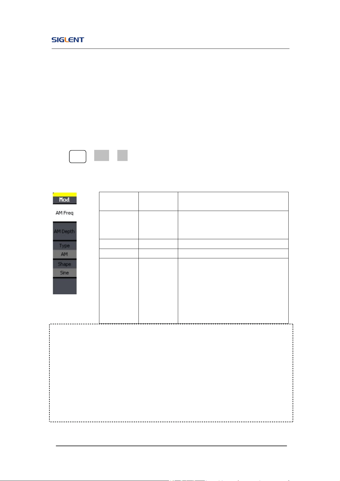
AM
The modulated waveform consists of two parts: the carrier waveform and the
modulating waveform. In AM, the amplitude of the carrier waveform varies
with the instantaneous voltage of the modulating waveform. The parameters
for the AM are in Figure 2- 29
Press Mod →Type→ AM, to enter the following menu.
Figure 2- 29 Table 2- 14 Menu Explanations of the AM Parameters
Term Explanation
Modulation Depth
The amplitude range (also called ‘Percentage Modulation’). Modulation depth
varies from 0% to 120%.
In the 0% modulation, the output amplitude is the half of the set one.
In the 100% modulation, the output amplitude is the same with the
set one.
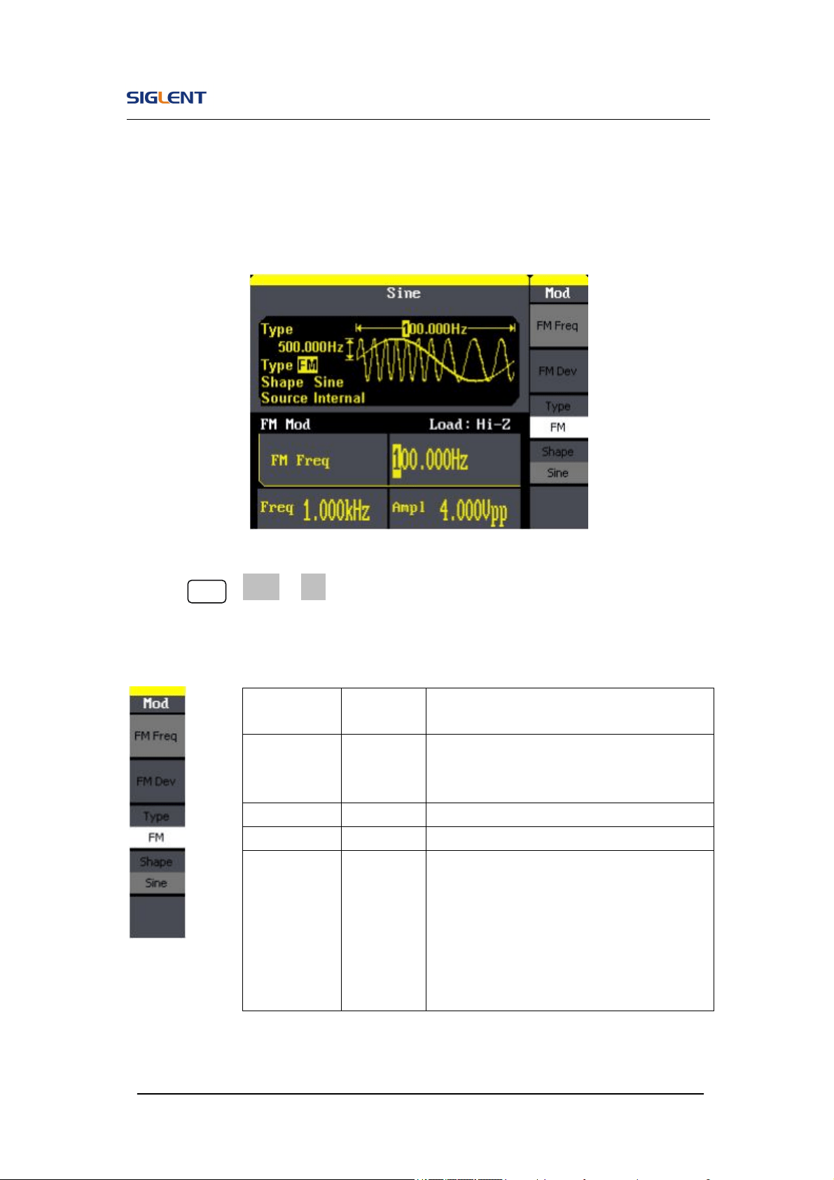
FM
Function
Menu
Settings Explanation
AM Freq
Set the modulating waveform
frequency. Frequency range:
2mHz~20kHz (internal source only).
AM Depth Set the amplitude range.
Type AM Amplitude modulation.
Shape
Sine
Square
Triangle
UpRamp
DnRamp
Noise
Arb
Choose the modulating waveform.
To change the carrier waveform
parameter, press Sine, Square, Ramp,
Arb
SDG800 User Manual 44
The modulated waveform consists of two parts: the carrier waveform and the
modulating waveform. In FM, the frequency of the carrier waveform varies
with the instantaneous voltage of the modulating waveform. The parameters
for the FM are as shown in Figure 2- 30.
Figure 2- 30 Setting Interface of FM Waveform Parameter
Press Mod →Type→ FM, to enter the following menu.
Figure 2- 31 Table 2- 15 Menu Explanations of the FM Parameters
Function
Menu
Settings Explanation
FM Freq
Set the modulating waveform frequency.
Frequency range 2mHz~20kHz (internal
source).
FM Dev Set the maximum frequency deviation
Type FM Frequency modulation
Shape
Sine
Square
Triangle
UpRamp
DnRamp
Noise
Arb
Choose the modulating waveform. To
change the carrier waveform parameter,
press Sine, Square, Ramp, Arb
SDG800 User Manual 45
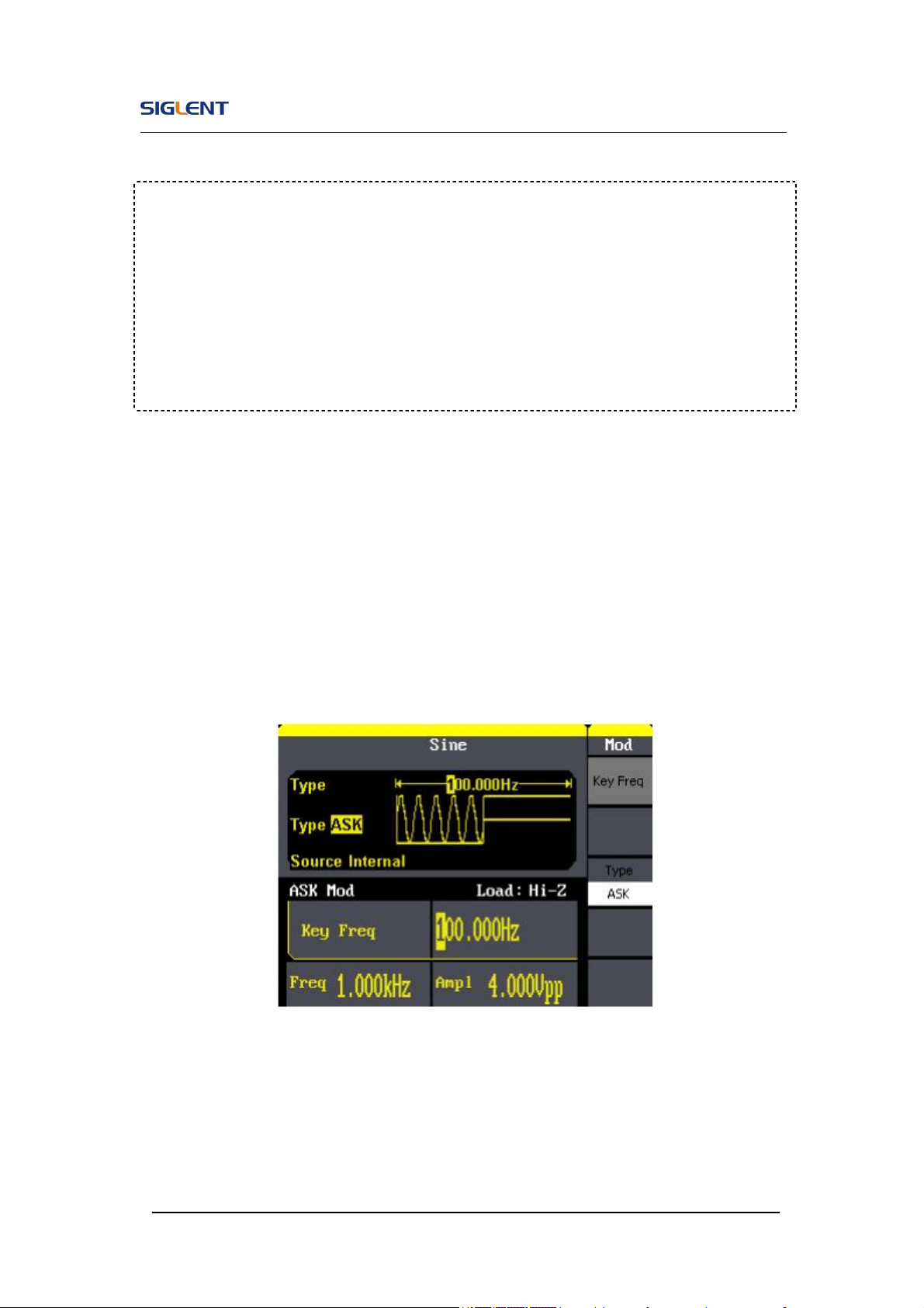
ASK
ASK is a form of modulation that represents digital data as variations in the
amplitude of a carrier wave. The amplitude of an analog carrier signal varies
in accordance with the bit stream (modulating signal), keeping frequency and
phase constant. The parameters for the ASK are as shown in Figure 2- 32
Figure 2- 32 Setting Interface of ASK Waveform Parameter
Term Explanation
Frequency Deviation
The deviation should be equal to or less than the carrier waveform
frequency.
The sum of the deviation and the carrier frequency should be equal to
or less than maximum frequency of the selected function.
SDG800 User Manual 46
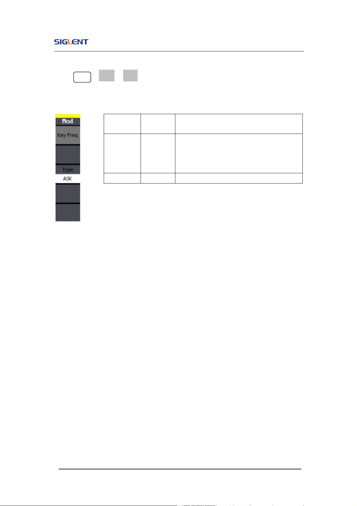
Press Mod →Type→ ASK, to enter the following menu.
Figure 2- 33 Table 2- 16 Menu Explanations of the ASK Parameters
Function
Menu
Settings
Explanation
Key Freq
Set the frequency at which the output
amplitude shifts between the carrier
amplitude and zero (internal modulation
only): 2mHz~50kHz.
Type ASK Amplitude shift keying modulation.
SDG800 User Manual 47
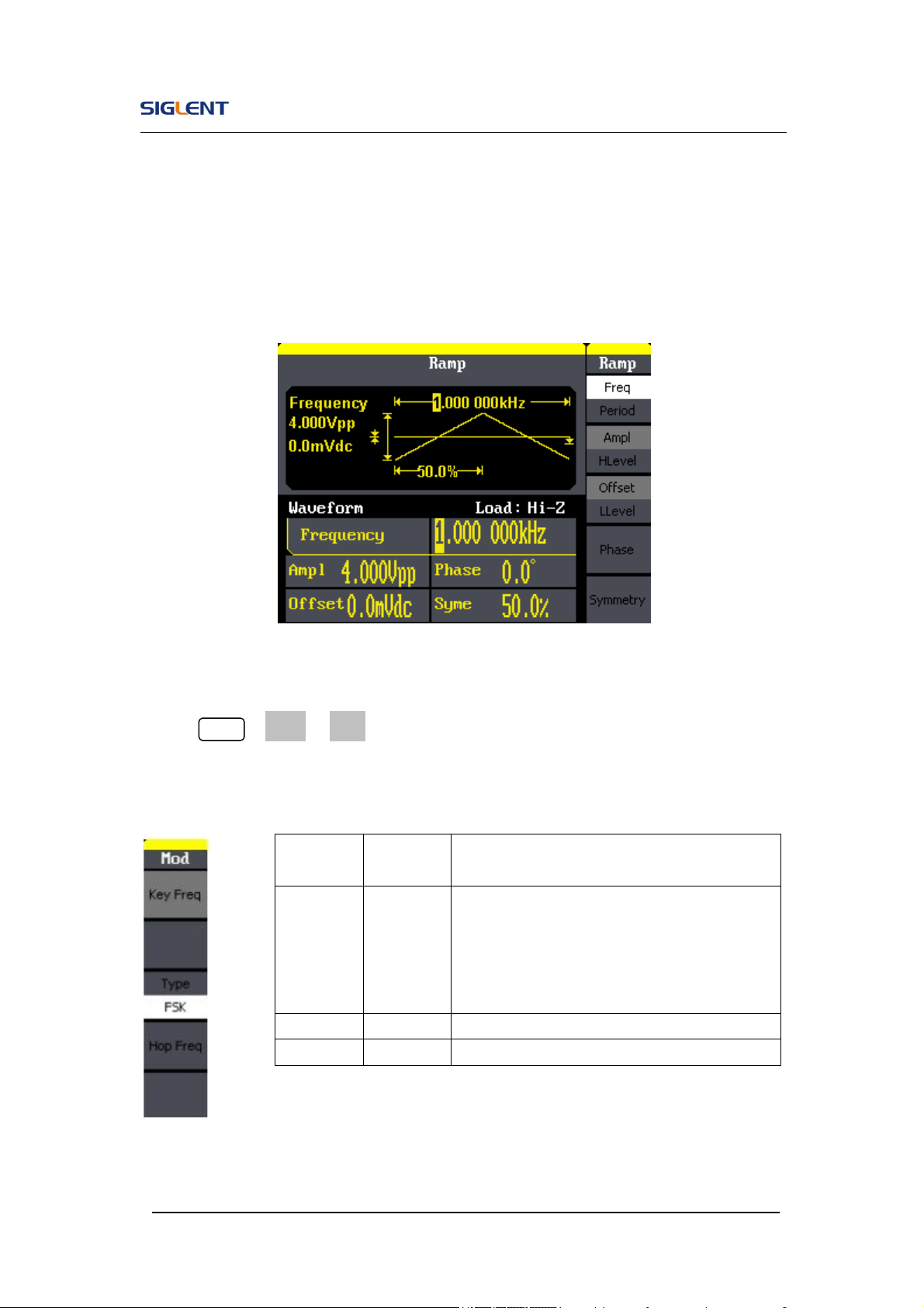
FSK
The FSK Modulation is a modulation method, the output frequency of which
switches between two the pre-set frequencies (carrier waveform frequency
and the hop frequency). The frequency at which the output frequency
switches is called the key frequency.
Figure 2- 34 Setting Interface of FSK Waveform Parameter
Press Mod →Type→ FSK, to enter the following interface
Figure 2- 35 Table 2- 17 Menu Explanations of the FSK Parameters
Function
Menu
Settings
Explanation
Key Freq
Set the frequency at which the output
frequency shifts between the carrier
frequency and the hop frequency (internal
modulation only):
2mHz~50kHz.
Type FSK Frequency shift keying modulation.
Hop Freq
Set the hop frequency.
SDG800 User Manual 48
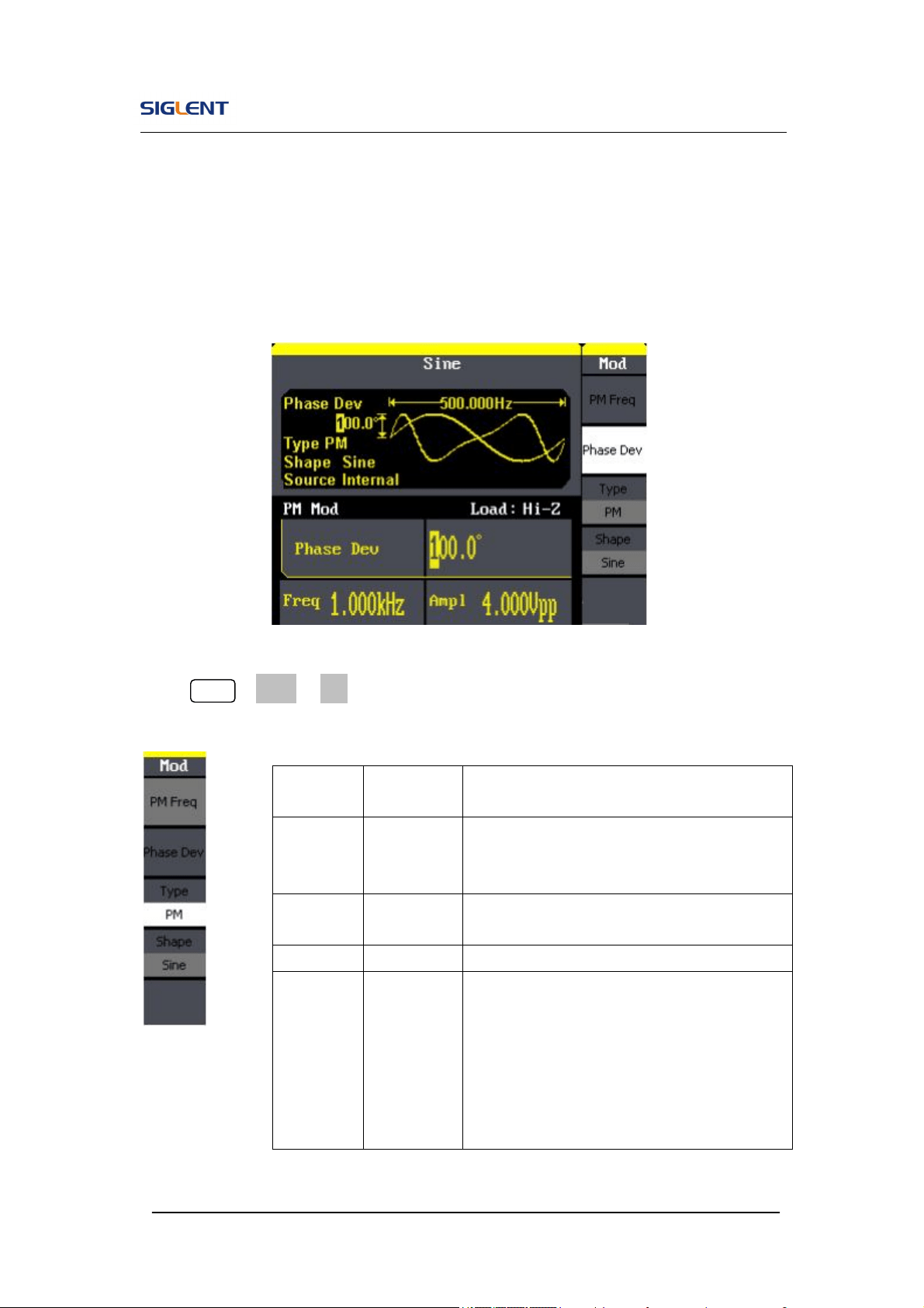
PM
The modulated waveform consists of two parts: the carrier waveform and the
modulating waveform. In PM, the phase of the carrier waveform varies with
the instantaneous voltage level of the modulating waveform. The parameters
for the PM are as shown in Figure 2- 36.
Figure 2- 36 Setting Interface of PM Waveform Parameter
Press Mod →Type →PM, enter the following interface.
Figure 2- 37 Table 2- 18 Menu Explanations of the PM Parameters
Function
Menu
Settings Explanation
PM Freq
Set the modulating waveform frequency.
Frequency range:
2mHz~20kHz
Phase
Dev
Range from 0° ~ 360°.
Type PM Phase modulation
Shape
Sine
Square
Triangle
UpRamp
DnRamp
Noise
Arb
Choose the modulating waveform.
To change the carrier waveform parameter,
press Sine, Square, Ramp, Arb
SDG800 User Manual 49
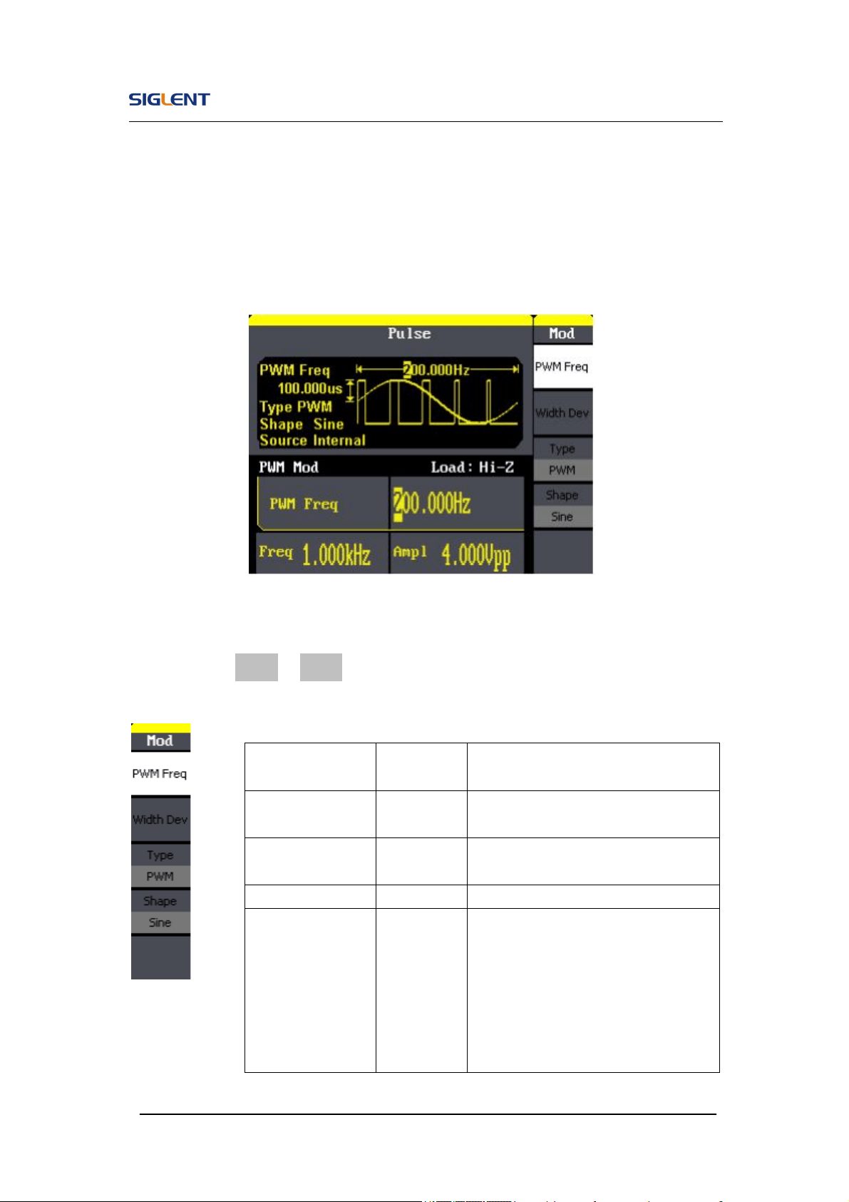
PWM
The modulated waveform consists of two parts: the carrier waveform and the
modulating waveform, the carrier waveform is only pulse. In PWM, the pulse
width of pulse varies with the instantaneous voltage of the modulating
waveform. The parameters for the FM are as shown in Figure 2- 38.
Figure 2- 38 Setting Interface of PWM Waveform Parameter
Press Mod→ Pulse →PWM, to enter the following menu.
Figure 2- 39 Table 2- 19 Menu Explanations of the PWM Parameters
Function
Menu
Settings Explanation
PWM Freq
Set the modulating waveform
frequency. 2mHz~20kHz
Width Dev
Duty Dev
Set the width or Duty range.
Type PWM Amplitude modulation.
Shape
Sine
Square
Triangle
UpRamp
DnRamp
Noise
Arb
Choose the modulating waveform.
The carrier waveform is pulse.
SDG800 User Manual 50
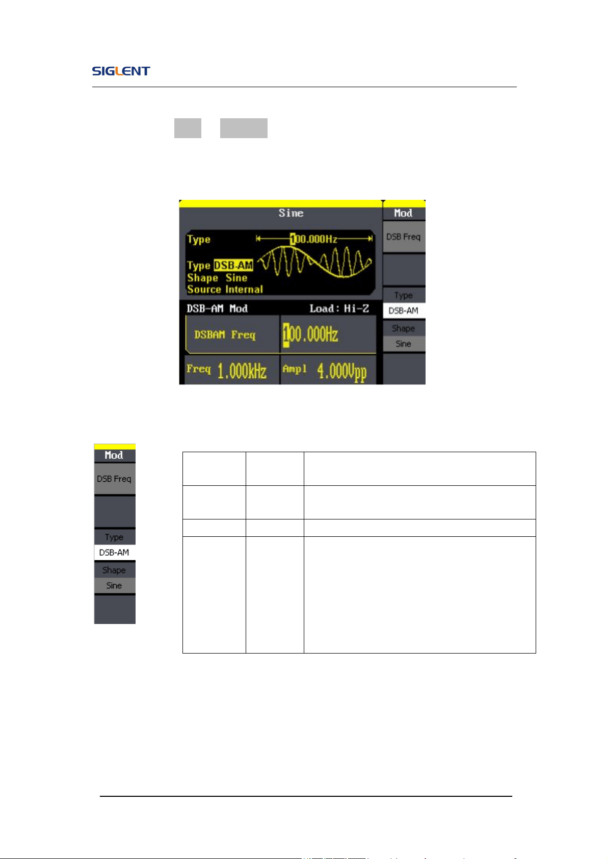
DSB-AM
Press Mod→ Type →DSB-AM. The parameters for the DSB-AM are as
shown in Figure 2- 40.
Figure 2- 40 Setting Interface of DSB-AM Waveform Parameter
Figure 2- 41 Table 2- 20 Menu Explanations of the DSB-AM Parameters
Function
Menu
Settings
Explanation
DSB Freq
Set the modulating waveform frequency.
Frequency range: 2mHz~20kHz
Type DSB-AM
Amplitude modulation.
Shape
Sine
Square
Triangle
UpRamp
DnRamp
Noise
Arb
Choose the modulating waveform.
To change the carrier waveform parameter,
press Sine, Square, Ramp, Arb
SDG800 User Manual 51
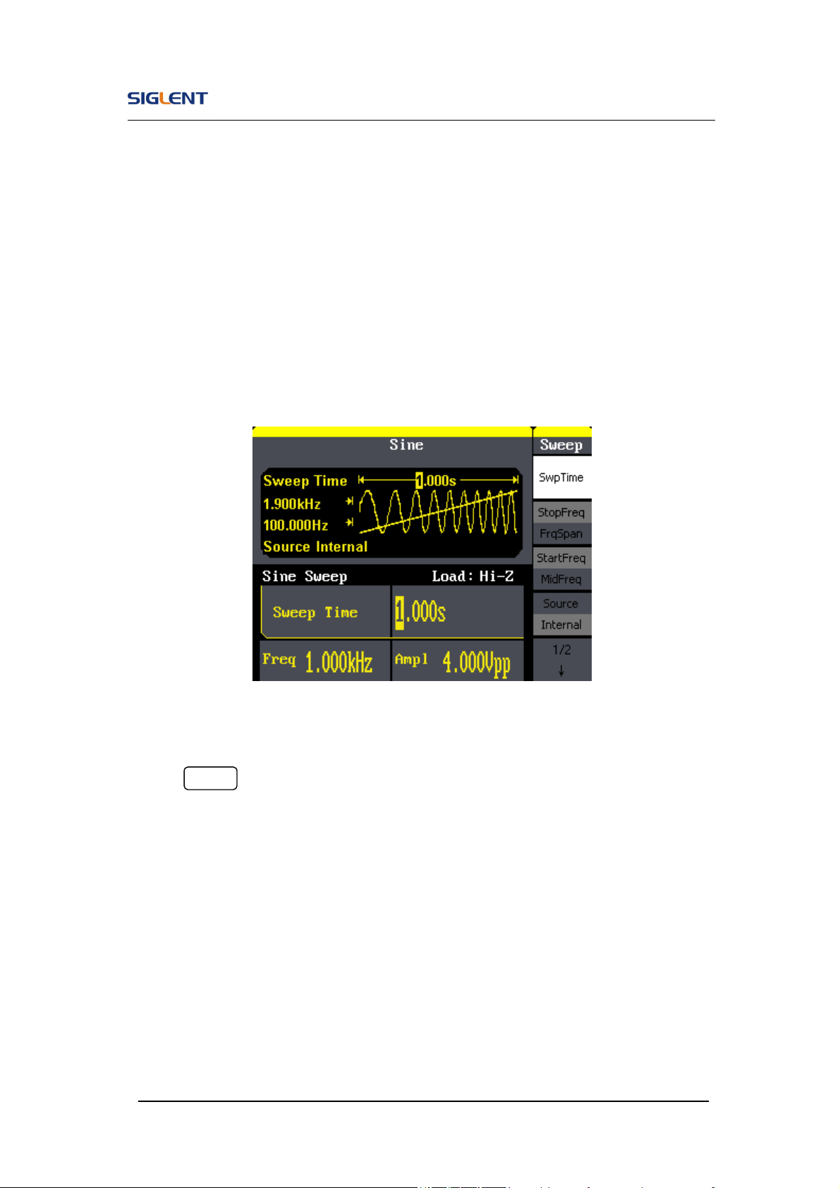
2.8. To Generate Sweep
In the frequency sweep mode, the function generator ‘steps’ from the start
frequency to the stop frequency at the sweep time you specify. Sweep can be
generated by sine, square, ramp or arbitrary waveforms (pulse, noise and DC
are not allowed).
Figure 2- 42 Setting Interface of Sweep Waveform Parameter
Press Sweep button to enter the following menu. Set the waveform
parameters by using the operation menu.
SDG800 User Manual 52
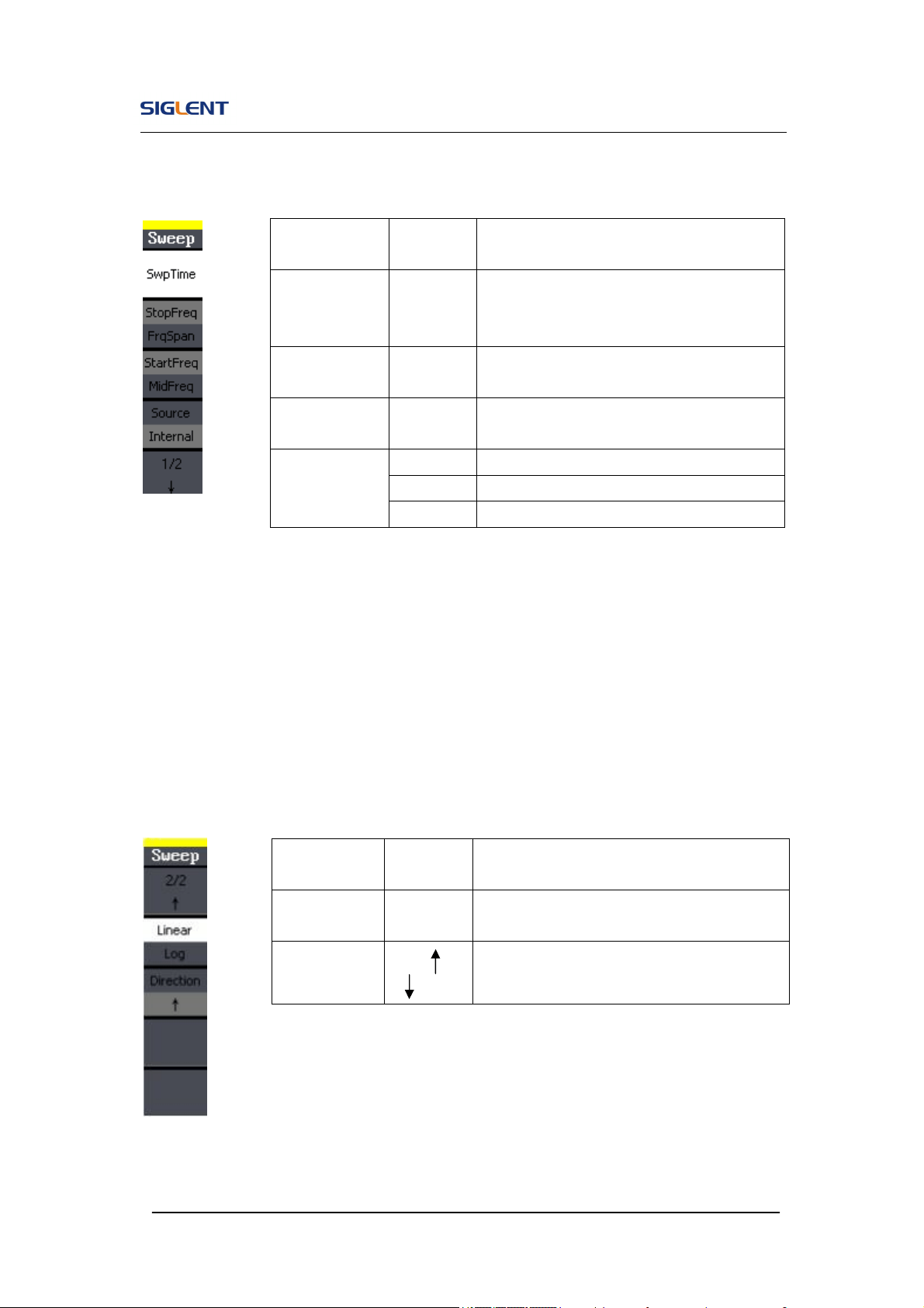
Figure 2- 43 Table 2- 21 Menu Explanations of Waveform Sweep (Page 1/2)
Sweep Frequency Setting
Use start freq and stop freq or center freq and freq span to set the range of
the frequency. Press the button again to switch between each other.
Figure 2- 44 Table 2- 22 Menu Explanations of Waveform Sweep (Page 2/2)
Function
Menu
Settings
Explanation
Swp Time
Set the time span of the sweep in which
the frequency changes from the start
frequency to stop frequency.
Stop Freq
Freq Span
Set the stop frequency of the sweep;
Set the frequency span of the sweep.
Start Freq
Mid Freq
Set the start frequency of the sweep;
Set the center frequency of the sweep.
Source
Internal Choose internal source.
External Choose external source.
Manual Set the start and stop time by hand.
Function
Menu
Settings
Explanation
Linear/
Log
Set the sweep with linear spacing;
Set the sweep with logarithmic spacing.
Direct
Sweep upward;
Sweep downward.
SDG800 User Manual 53
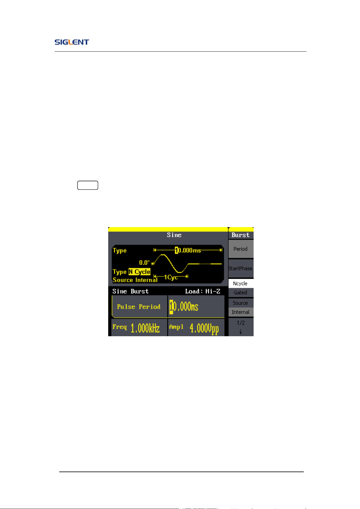
2.9. To Generate Burst
Burst function can generate versatile waveforms in burst, which can last
specific times of waveform cycle (N-Cycle burst), or when external gated
signals (gated burst) is applied, any waveform could be used, but noise can
only be used in Gated Burst.
Press Burst button to enter the following interface. Set the waveform
parameters by using the operation menu.
Figure 2- 45 Setting Interface of Burst Waveform Parameter
SDG800 User Manual 54
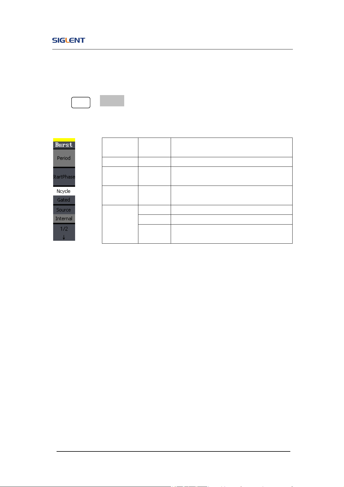
Set the N-Cycle Burst
Press Burst → N Cycle, to enter the following interface.
Figure 2- 46 Table 2- 23 Menu Explanations of the N-Cycle Parameters(Page 1/2)
Burst Period
Set the time span between an N-Cycle burst and the next. If necessary the
period will increase to allow the specific number of cycles in a burst. Burst
Period>Carrier Period × Burst Number
Start Phase
Define the start point in a waveform. The phase varies from 0° to 360°, and
the default setting is 0°. For an Arbitrary Waveform, 0° is the first waveform
point.
Function
Menu
Settings
Explanation
Period Set the burst Period.
Start
Phase
Set the start phase of the burst.
NCycle
Gated
Use the N-Cycle mode.
Use the Gated mode.
Source
Internal Choose internal source.
External Choose external source.
Manual
Choose external source, set the start time
by hand.
SDG800 User Manual 55
N-Cycle/Gated
N-Cycle has specific number of waveform cycles, and every burst is activated
by a trigger event. Gated burst use external source to control burst as when
to be activated.
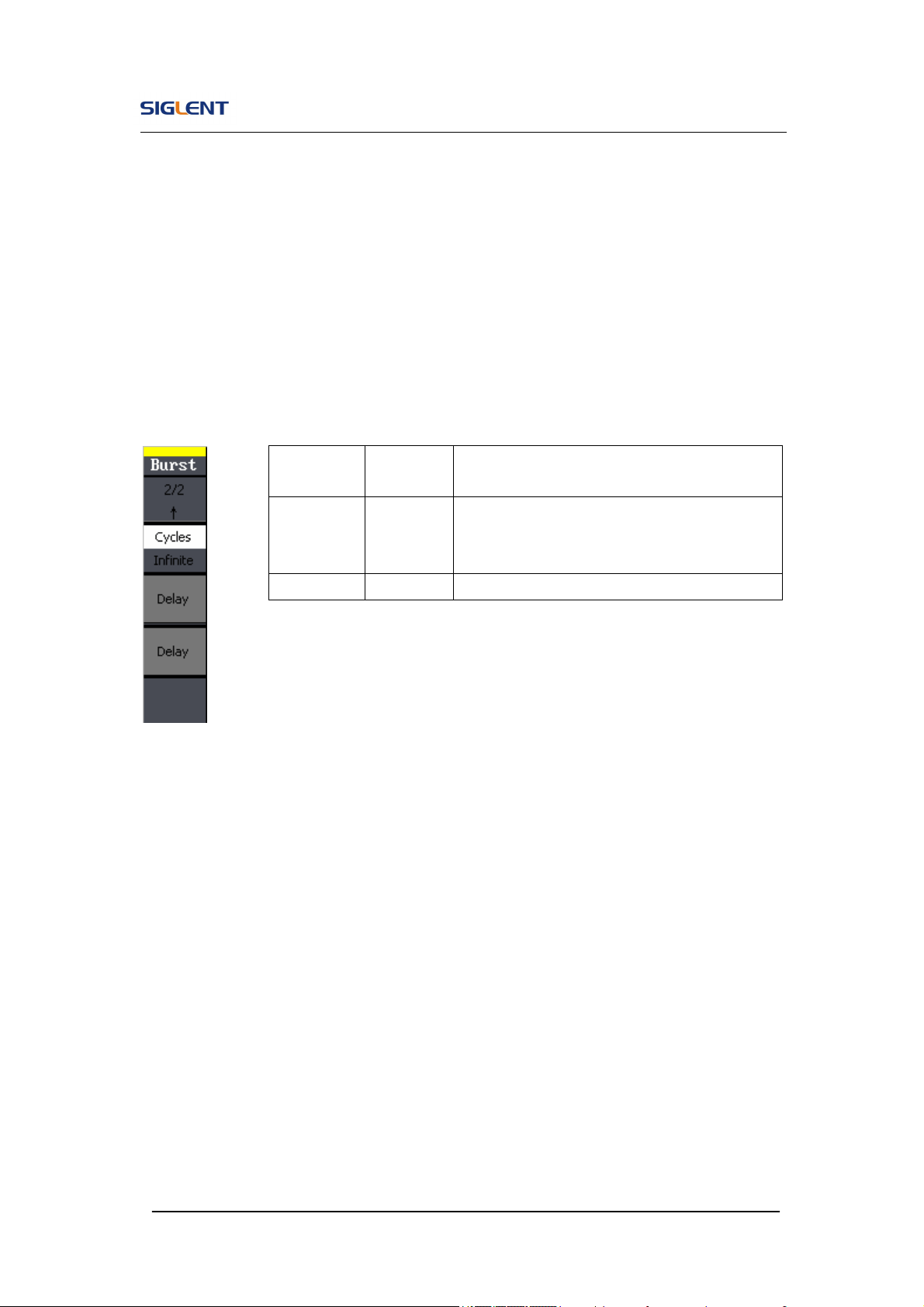
Figure 2- 47 Table 2- 24 Menu Explanations of the N-Cycle Parameters (Page2/2)
Cycles
Set the number of waveform cycle in an N-Cycle (1 to 50,000 or Infinite).
If you choose Infinite, then a continuous waveform will be generated which
will not stop until a trigger event happens.
If needed, Burst Period will increase to cater to the specific number
of cycles.
For an infinite-cycle burst, external or manual trigger is needed to
activate burst.
Function
Menu
Settings
Explanation
Cycles/
Infinite
Set the number of the bursts in a N-Cycle.
Set the number of the bursts in a N-Cycle to
be infinite.
Delay Set the delay time before the burst starts.
SDG800 User Manual 56
Delay
Set the time delay between the trigger input and the start of the N-Cycle burst.
The max delay is 240ns.
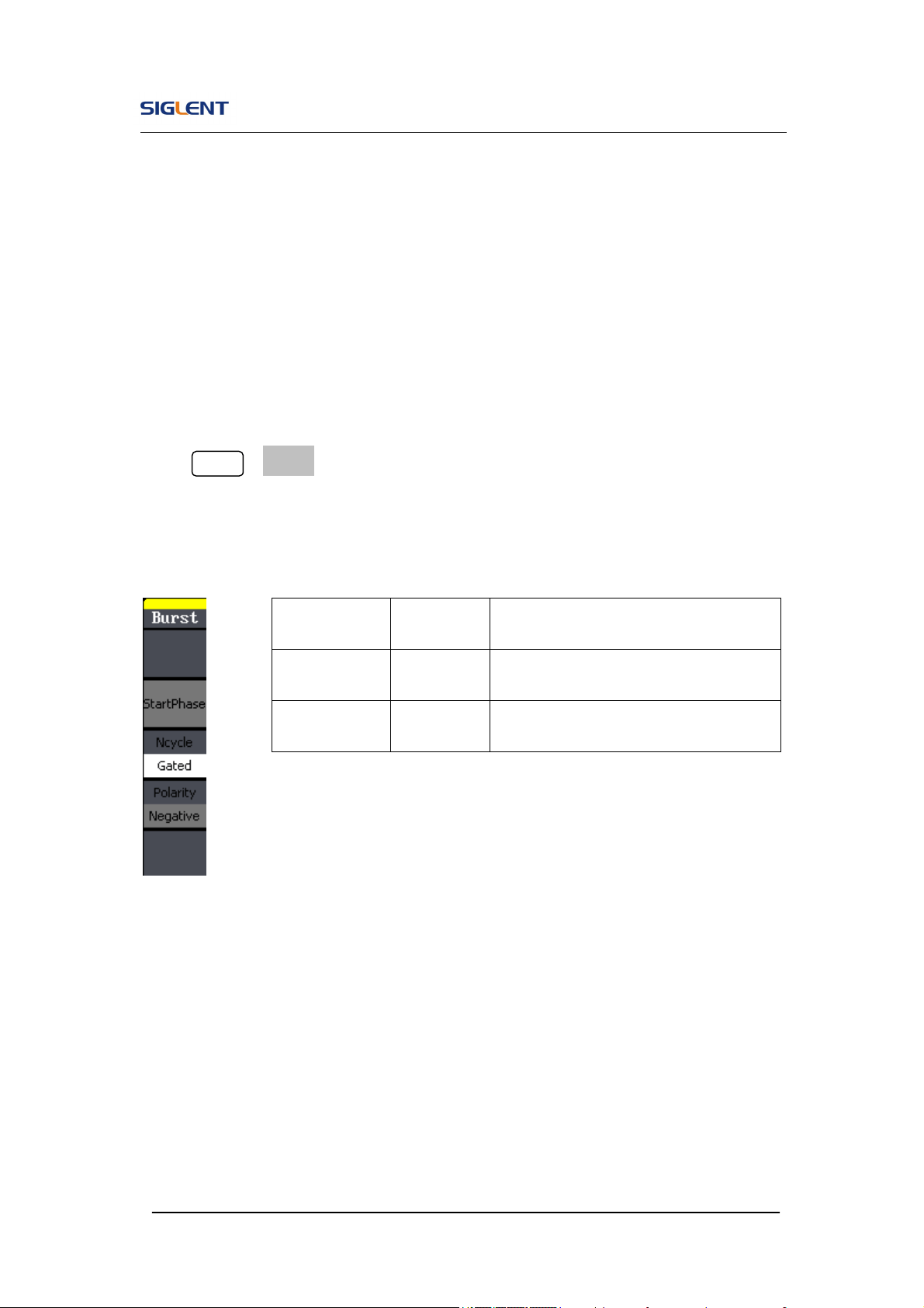
Set the Gated Burst
Press Burst →Gated, to enter the following interface.
Figure 2- 48 Table 2- 25 Menu Explanations of the Gated Burst Parameters
Function
Menu
Settings Explanation
NCycle
Gated
Set the NCycle mode;
Set the gated mode.
Polarity
Positive
Negative
Set the polarity for the gated signal.
SDG800 User Manual 57
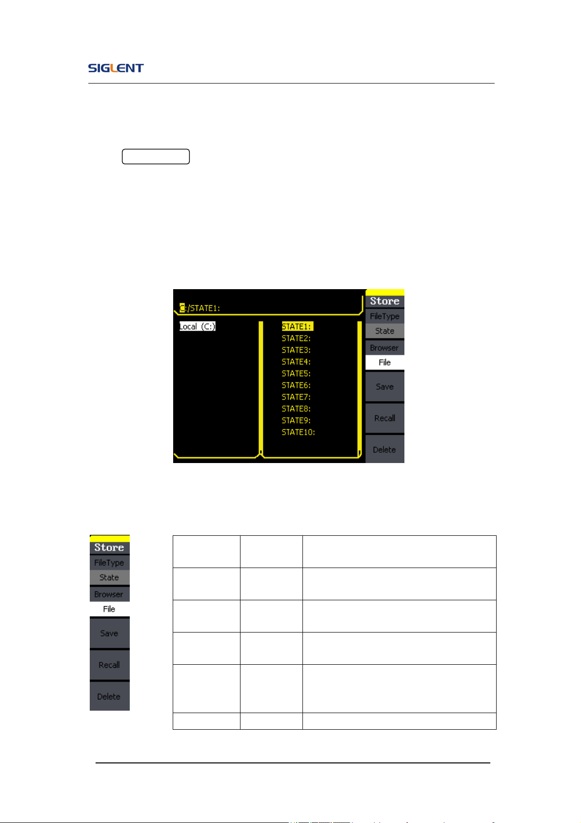
2.10. To Store and Recall
Press Store/Recall button to enter the following interface. You can save or
recall the state documentation inside the generator. The state file on the U
Disk is also allowed to recall or delete. File names can only be English. User
can only recall or delete the data documentation you save via CSV of the
Oscilloscopes.
Figure 2- 49 Save and Read Interface
Figure 2- 50 Table 2- 26 Menu Explanations of Save and Recall (Page 1/2)
Function
Menu
Settings Explanation
File Type
State
Data
The setting of the generator;
Arbitrary waveform file;
Browser
Directory
File
Shift between the directory and file.
Save
Save the waveform to the appointed
place.
Recall
Recall the waveform or setting
information in the specific position of the
memory.
Delete Delete the selected file.

SDG800 User Manual 58
About the browser
The directory selection shift is done by the direction keys. In the directory
mode, pressing the right key will open the lower directory while the left key
will fold the directory. Up and down key are used to shift between the
directories;
To Save the Instrument State
Users are allowed to store the instrument state in any of the 10 non-volatile
memories. The state storage will ‘memorize’ the selected function (including
the arbitrary waveform, frequency, amplitude, DC offset, duty cycle, symmetry,
and other modulation parameter used.)
To save the instrument state, the procedures are given as followed:
1. Choose the file type to store
Press Store/Recall →Type→ State, and choose state as the storage
type.
2. Choose the location of the file.
There are ten positions in the Local(C :), choose anyone of them by
rotating the knob.
3. Name the file and save it
Press Save button, enter the desired name. Press Save to finish.
SDG800 User Manual 59
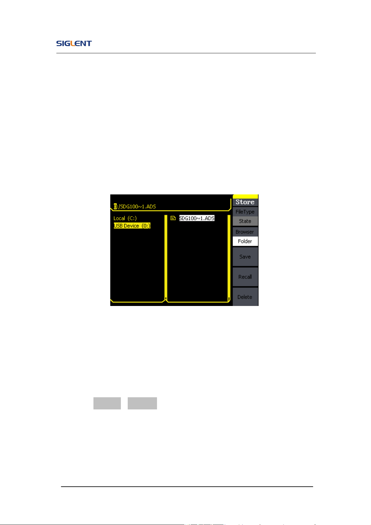
To Use USB Storage
As is shown in Figure 2- 51, the storage location is divided into: The internal
storage Local(C :) and the U Disk storage USB Device (A :). At the left side of
the front panel, there is a USB interface. When a USB storage is connected,
the storage menu will show ‘USB Device (A:)’. Otherwise, the default location
is the internal location Local(C :).
Figure 2- 51 USB Storage Interface
1. Install the USB Device
Insert the USB Device into the USB interface on the front panel, and the
screen will show ‘USB flash device plug in’, and storage menu will show
‘USB Device (A :)’
2. Choose the USB Device
Press Browser->Directory, move the cursor with the up or down direction
key to select ‘USB Device (A :)’. Press the right key to open the lower
directory, use the up and down direction key to choose the file ‘SDG800’.
Use the right key to open the lower directory, and up and down key to
select the file ‘Workspace’. Input the file name and save.
SDG800 User Manual 60
3. Remove the USB Device
Remove the USB Device from the interface. The system will inform you
‘USB flash device plug out’, and the ‘USB Device (A :)’ in the storage
menu will disappear.
Note: USB Device can only be used by U Disk; portable hard disk is not
supported.
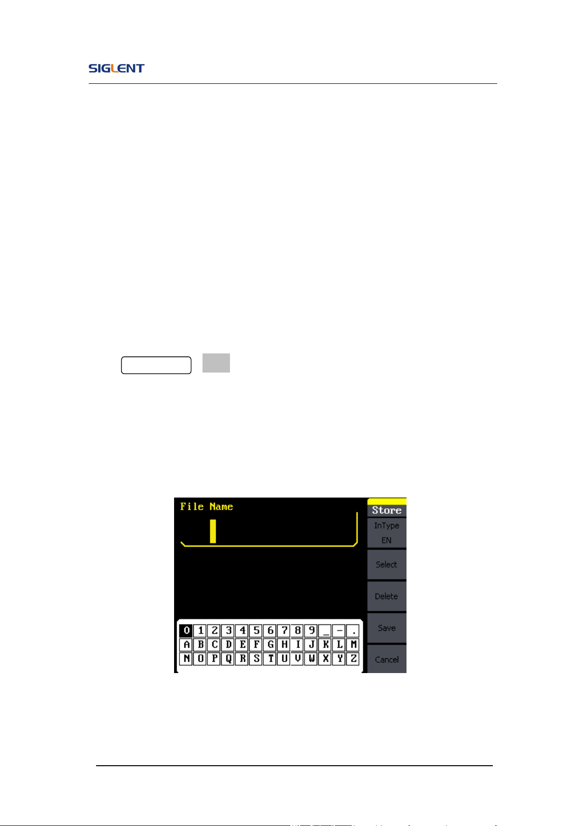
To Save a File
Press Store/Recall →Store, to enter the following interface. Enter the desired
file name in the ‘File Name’ frame. In the middle of the figure below is the
input keypad, used to edit the file name. Use the up and down direction keys
and knob to select the desired character; use the left and right direction keys
to edit the input file name.
Figure 2- 52 File Storage Interface
SDG800 User Manual 61
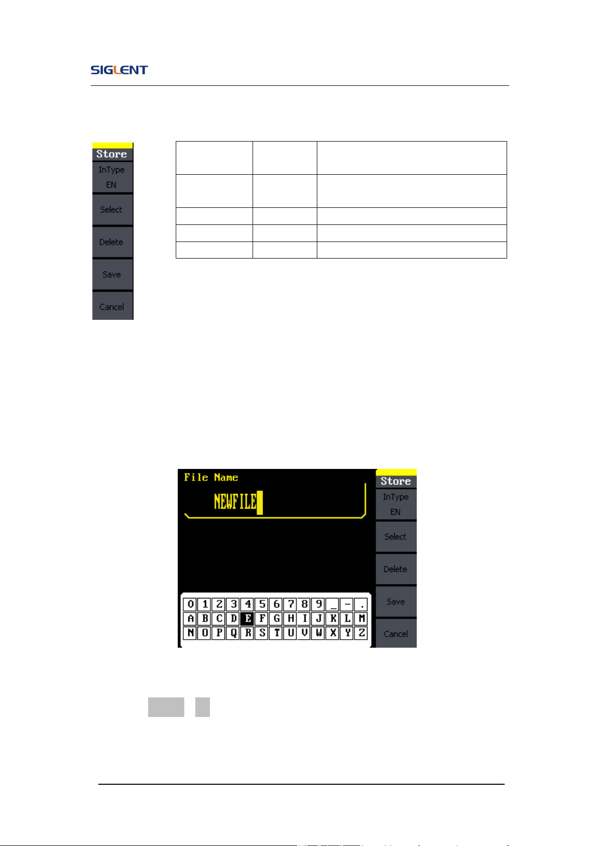
Figure 2- 53 Table 2- 27 Menu Explanation of File Storage
1. English Input
The English input interface is as shown in Figure 2- 54, to save a file named
‘NEWFILE’, follow the steps below:
Figure 2- 54 English Input Interface
(1) Press InType->En, to enter the English interface.
(2) Input the file name’ NEWFILE’.
Use the Knob to adjust the cursor’s horizontal position and the up and
Function
Menu
Settings Explanation
Input
Type
En English input.
Select Select the current character.
Delete Delete the current character.
Save Store the file with the current name

SDG800 User Manual 62
down key to adjust the vertical position. Select the Character ‘N’ and
press Select. Repeat this until you have inputted ‘NEWFILE’.
(3) Edit the File Name
When you have entered a wrong character, move the cursor to the
wrong character to be deleted and press Delete to remove it. Reenter
the file name.
(4) Press Save, to finish and save the file.
SDG800 User Manual 63
2.11. To Set the Utility Function
With the Utility Function, you can set the parameters of the generator such as:
DC On/Off, Sync On/Off, Output Parameter, Interface Parameter, System
Setting and Testing Parameter. The DC switch offers the options of DC output
or Arbitrary Waveform Output. Sync Switch offers the option to choose the
Sync Signal or not. Output Setting provides the parameter setting for
Load/HighZ and Normal/Inverse. The System Setting provides the setting for
Language, Display, Beep, Screen Guard, Format, Power System Configure
and default setting; Test provides the self-testing and calibration function.
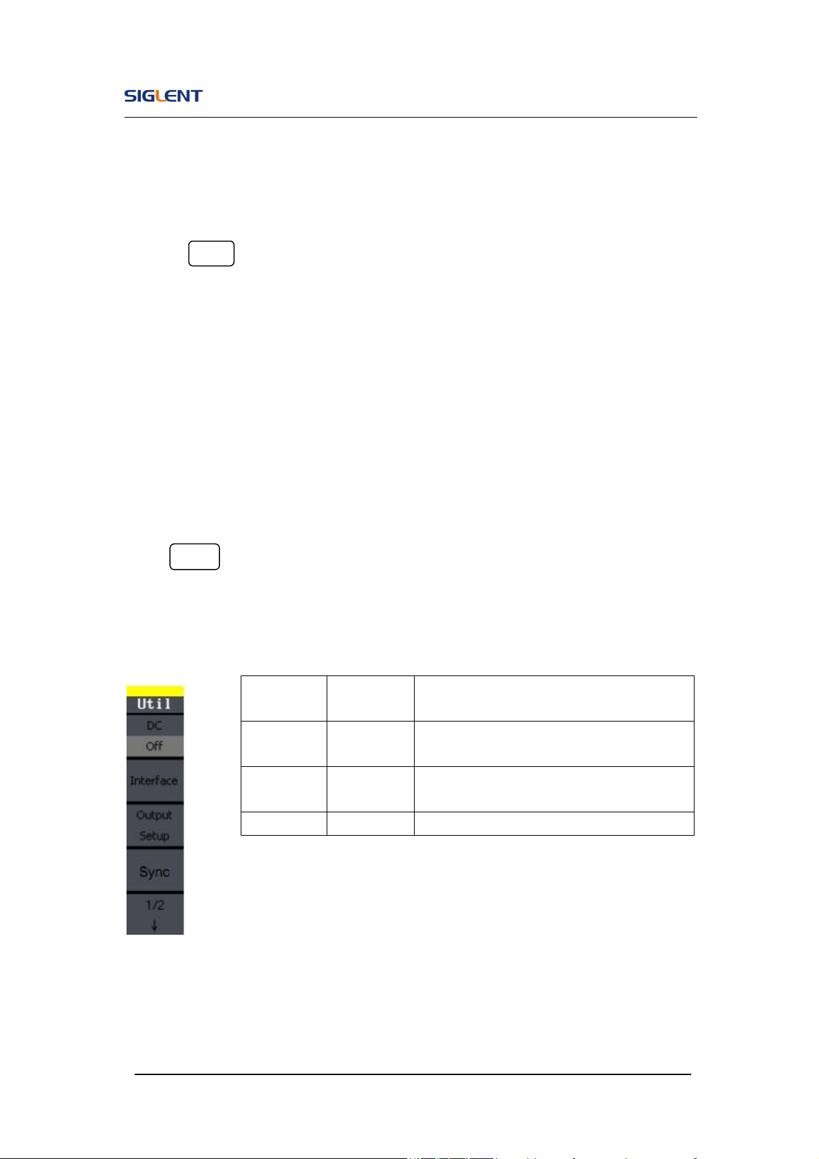
Press Utility button, to enter the Utility Menu. Its functions are listed below in
Figure 2- 55
Figure 2- 55 Table 2- 28 Menu Explanations of Utility System Setting (Page1/2)
Function
Menu
Settings Explanation
DC
On
Off
Set the output waveform to be DC.
Set the output waveform to be arbitrary.
Output
Setup
Set the output parameter.
Sync Set the sync output
SDG800 User Manual 64
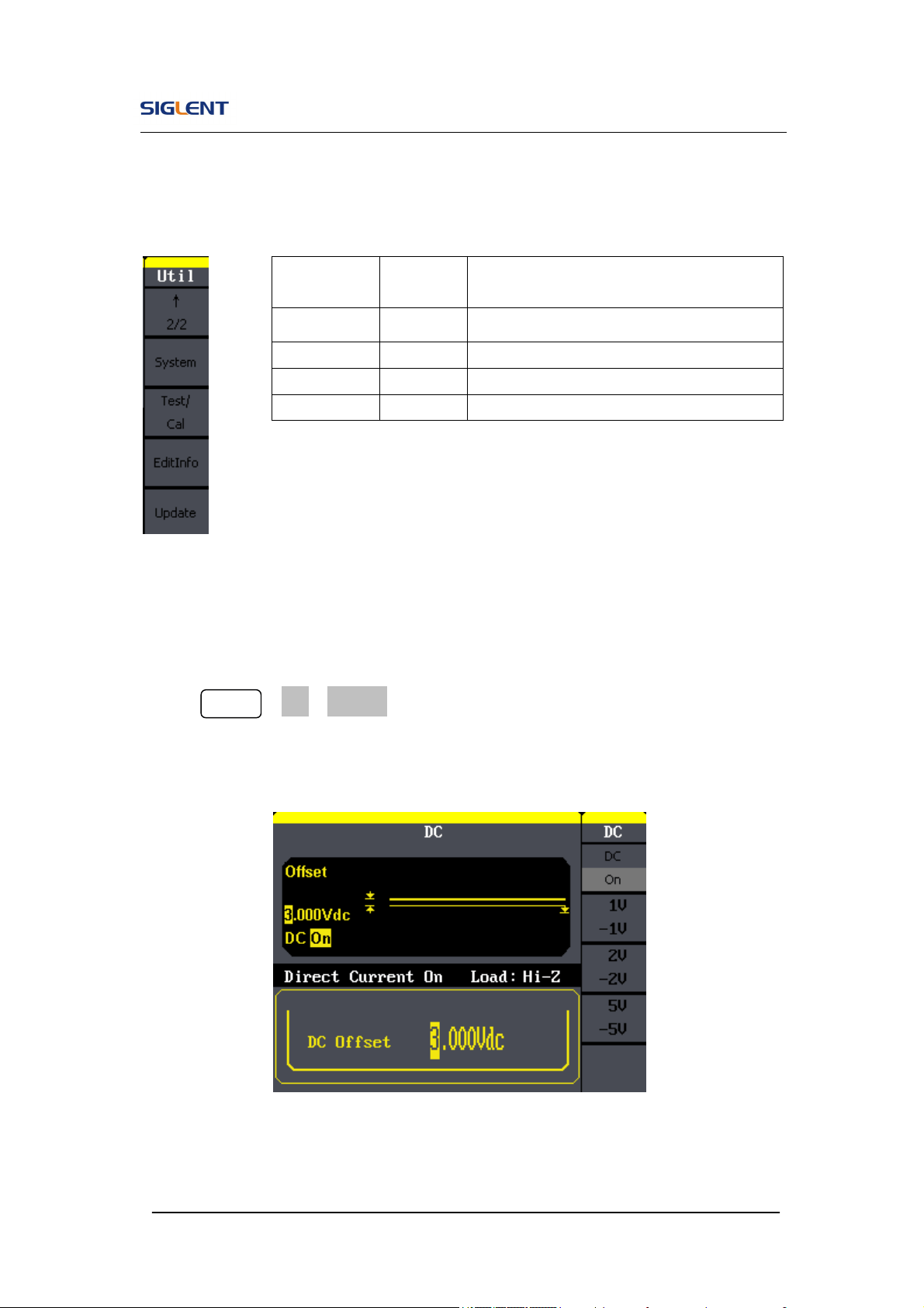
Figure 2- 56 Table 2- 29 Menu Explanations of Utility System Setting (Page2/2)
To Set the DC Output
Press Utility →DC→DC On, to enter the following interface. Please note
that there is a ‘DC On’ sign at the middle left of the screen.
Figure 2- 57 DC Setting Interface
Function
Menu
Settings
Explanation
System Set the system configuration.
Test/Cal Test and calibrate the instrument.
EditInfo Information of the system.
Update Update function.
SDG800 User Manual 65
DC Offset
Set the DC voltage level.
To Shift into the Arbitrary Waveform Output
1. Press Utility →DC→DC Off, to close DC output and return to arbitrary
waveform output.
2. Press any functional button, and the waveform output setting turns into
the arbitrary waveform output. The DC output is turned off automatically.
To Set IO
Press Utility →IO Setup, to set the IO interface. The equipment stands for
RAW protocol and TMC protocol, user may setup corresponding protocol by
IO Setup.
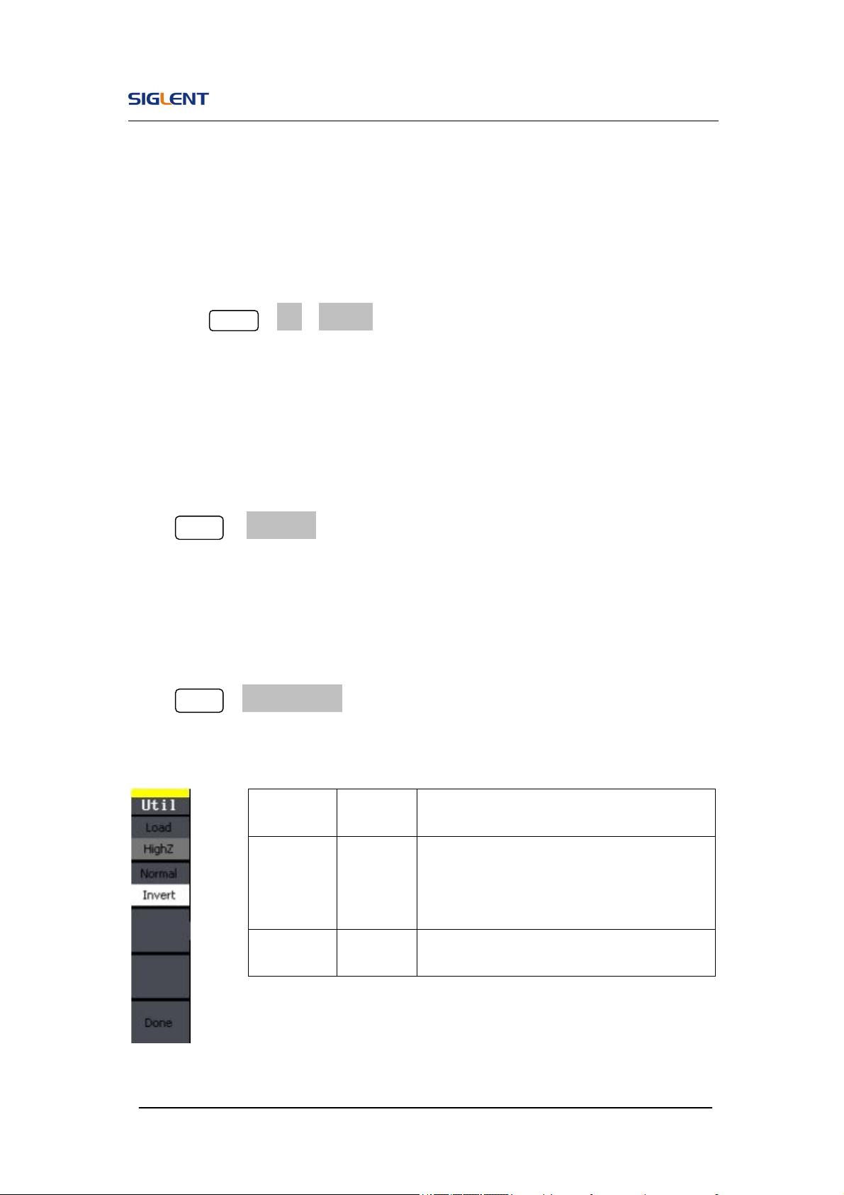
To Set Output Parameter
Press Utility →Output Setup, to enter the following interface.
Figure 2- 58 Table 2- 30 Menu Explanations of Output Setting (Page 1/2)
Function
Menu
Settings
Explanation
Load
HighZ
Set the load connected to the Output
Connector;
Set the load connected to the Output
Connector to be HighZ.
Normal
Invert
Normal output;
Inverse output.
SDG800 User Manual 66
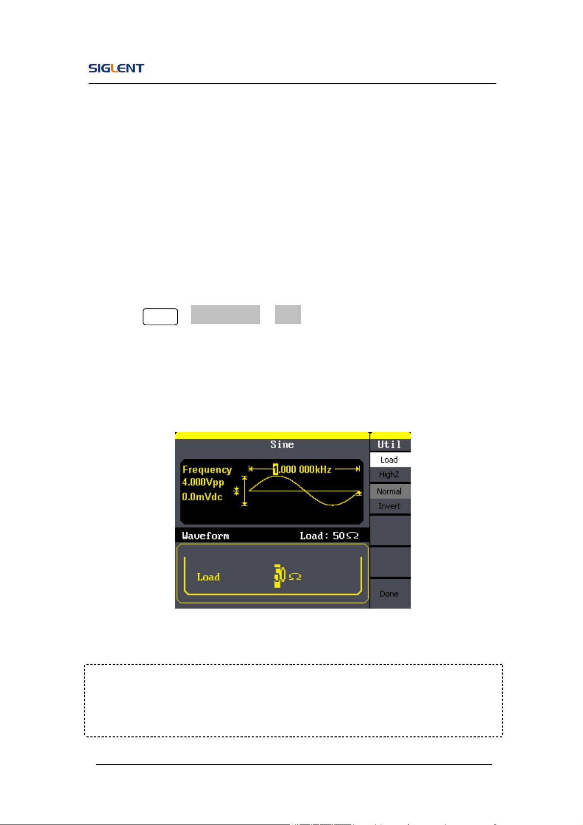
1. To Set the Output Load
For the [Output] connector on the front panel, the generator has a built-in
50Ω series impendence. If the actual load does not match the set one,
the displayed amplitude and offset will be incorrect. This function is used
to match the displayed voltage with the expected one.
Steps for setting the load:
Press Utility →Output Setup→ Load, to enter the following interface.
Please note that the load parameter shown on the right
bottom is the default setting when the power is on or the pre-set load
value. If the current value is valid for the output, then current value will be
used.
Figure 2- 59 Set the Output Load
Instruction
SDG800 Series has a fixed 50Ω Series Impendence. No matter what value the
set parameter is, if the real load is different from the set one, the displayed

SDG800 User Manual 67
voltage will not equal the real voltage.
2. To Set the Invert Waveform
Press Utility →Output Setup→ Invert, to set the Inverse Waveform Output.
When the waveform is inverse, no offset will change.
3. To Set the Sync Output
The generator provides Sync output through the [Sync] connector on the rear
panel. All standard output functions (except DC and Noise) have a
corresponding Sync signal. For some applications, they can be disabled if
users do not want to use it,
In the default setting, the Sync signal should be connected to the
[Sync] connector (activated). When the Sync Signal is disabled, the
output voltage of the [Sync] connector is level low.
In the Inverse Mode, the Waveform that corresponds to the Sync
Signal does not inverse.
The Sync Signal is a Pulse Signal with fixed positive pulse width,
which is more than 50ns.
For non-modulated waveform, the Sync Signal reference is the
carrier.
For internal modulating AM, FM and PM, the Sync signal reference
is the modulated signal (not the carrier signal).
For ASK and FSK, the Sync Signal Reference is the keying
Frequency.
For a Sweep, when the sweep starts, the Sync Signal becomes TTL
Level High. The Sync frequency equals the specific Sweep time.
SDG800 User Manual 68
For the Burst, when the burst starts, the Sync Signal is Level High.
For the External Gated Burst, the Sync Signal follows the External
Gated Signal.
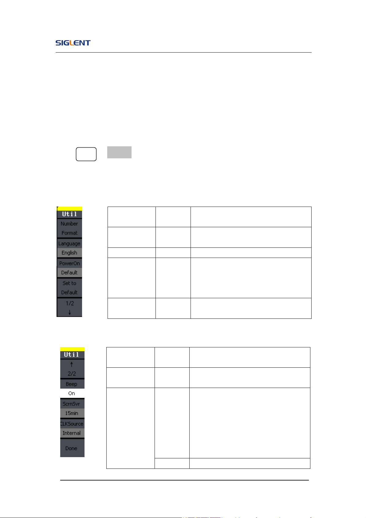
To Set the System
Press Utility → System, to enter the following interface.
Figure 2- 59 Table 2- 31 Menu Explanations of System Setup (Page 1/2)
Figure 2- 60 Table 2- 32 Menu Explanations of System Setup (Page 2/2)
Function
Menu
Settings
Explanation
Number
format
Set the number format.
Language Set the display language.
Power On
Default
Last
All the settings return to default when
powered;
All the settings return to the last one
when powered.
Set to
Default
Set all the settings to default.
Function
Menu
Settings
Explanation
Beep
On
Off
Open beep;
Close beep.
ScrnSvr
1min
5min
15min
30min
1hour
2hour
5hour
Activate the screen saver program.
Screen saver will be on if no action is
taken within the time that you have
selected. Press any button the resume.
Off Deactivate the screen saver program.
SDG800 User Manual 69
Key points:
Power On
Choose the configuration setting when the machine is powered.
Two choices are available: the default setting and the latest. Once selected,
the setting will be used when the instrument is powered.
Beep
Activate or deactivate the sound when an error occurs from the front panel or
the remote interface. Activate or deactivate any sound made by the button or
knob on the front panel. The current setting is stored in the non-volatile
memory.
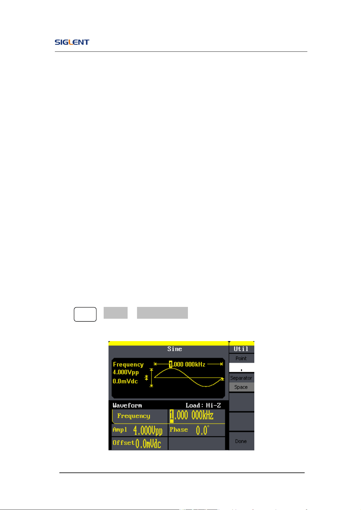
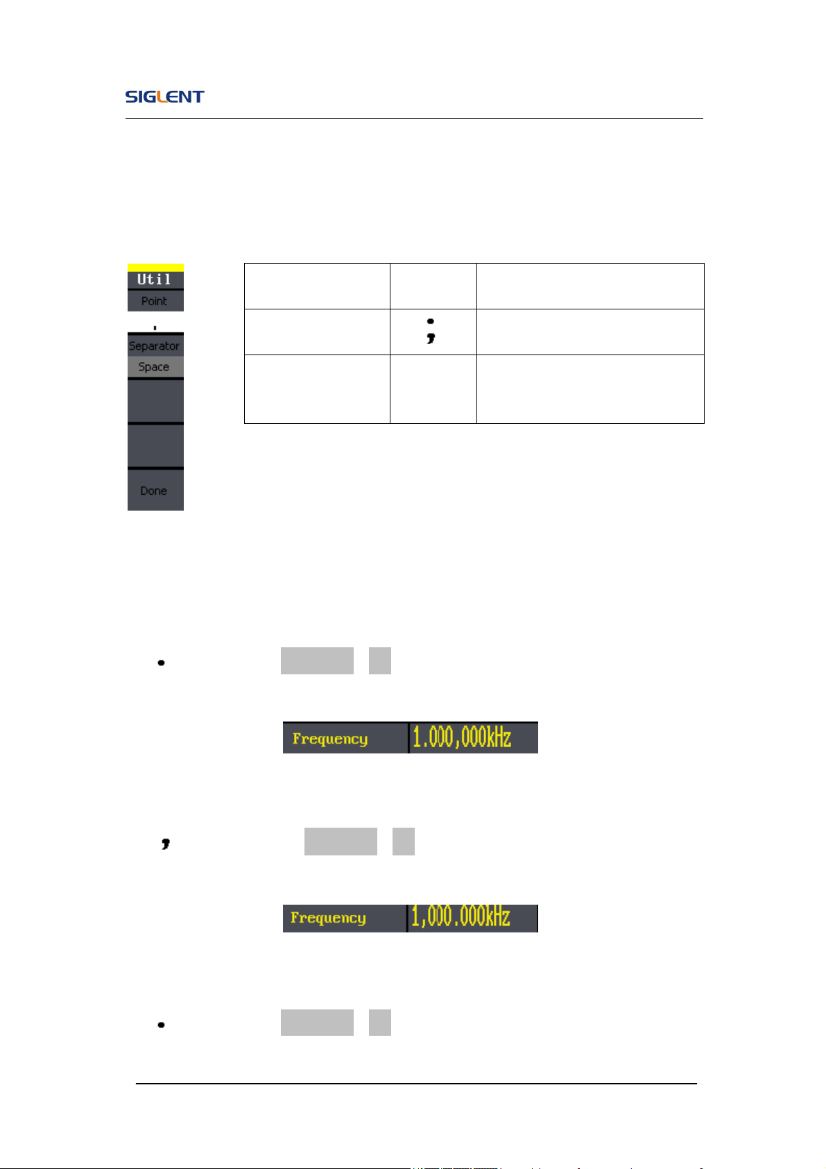
1. Set the Format
Press Utility →System→ Number Format, to enter the following interface.
Figure 2- 61 Set the number Format
SDG800 User Manual 70
Figure 2- 62 Table 2- 33 Menu Explanations of Setting the Number Format
According to the different choices of the point and the separator, the format
can have various forms.
(1) as point, press Separator->On, the example is as followed:
Figure 2- 63 Set Format
(2) as point, press ->Separator->On, the example is as followed:
Figure 2- 64 Set Format
(3) as point, press Separator->Off, the example is as followed:
Function
Menu
Settings Explanation
Point
Using dot to represent point;
Using comma to represent point.
Separator
On
Off
Space
Enable the Separator;
Close the Separator;
Use Space to separate.
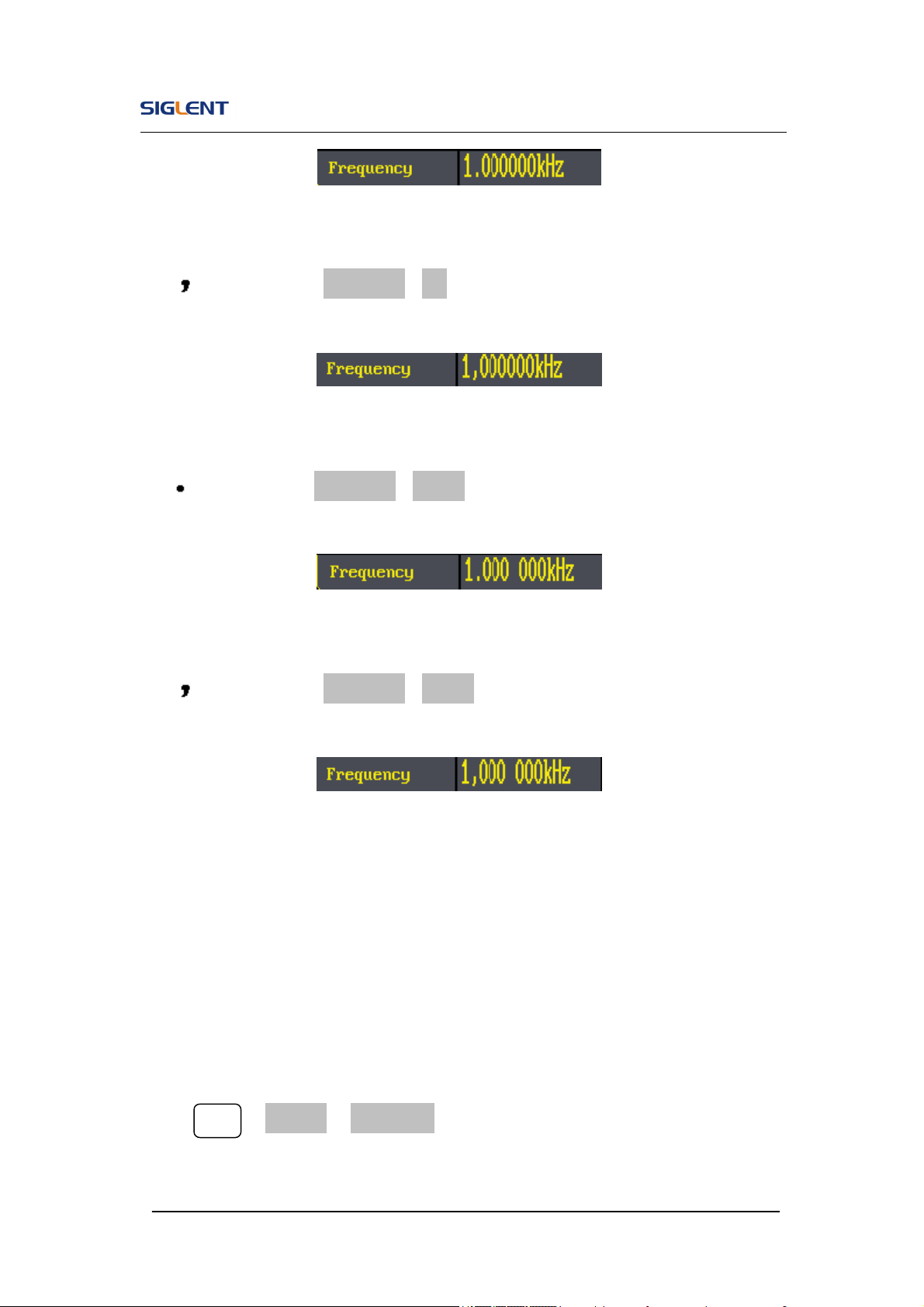
SDG800 User Manual 71
Figure 2- 65 Set Format
(4) as point, press Separator->Off, the example is as followed:
Figure 2- 66 Set Format
(5) as point, press Separator->Space, the example is as followed:
Figure 2- 67 Set Format
(6) as point, press Separator->Space, the example is as followed:
Figure 2- 68 Set Format
2. Language Setup
The SDG800 Series Generator offers two languages (English and Simplified
Chinese) for user to choose.
To Select Language, press Utility and then Language to select the language.
The Procedure is as followed:
Press Utility →System→ Language, to change the language.

SDG800 User Manual 72
3. To Return to Default Setting
Press Utility →System→ Set to Default, to set the system to the default
setting. The default settings of the system are as followed:
Table 2- 34 Factory Default Setting
Output Default
Function Sine Wave
Frequency 1kHz
Amplitude/Offset 4Vpp/0Vdc
Phase 0°
Terminals High Z
Modulation Default
Carrier 1kHz Sine Wave
Modulating 100Hz Sine Wave
AM Depth
100%
FM Deviation 500Hz
Key Freq 100Hz
Key Freq 100Hz
FSK Hop Frequency 1MHz
Phase Deviation 180°
Sweep Default
Start/Stop Frequency 100Hz/1.9kHz
Sweep Time 1S
Trig Out Off
Mode Linear
Direction ↑
Burst Default
Period 10ms
Phase 0°
Count 1Cycle
Trig Off
Trigger Default

SDG800 User Manual 73
Source Internal
SDG800 User Manual 74
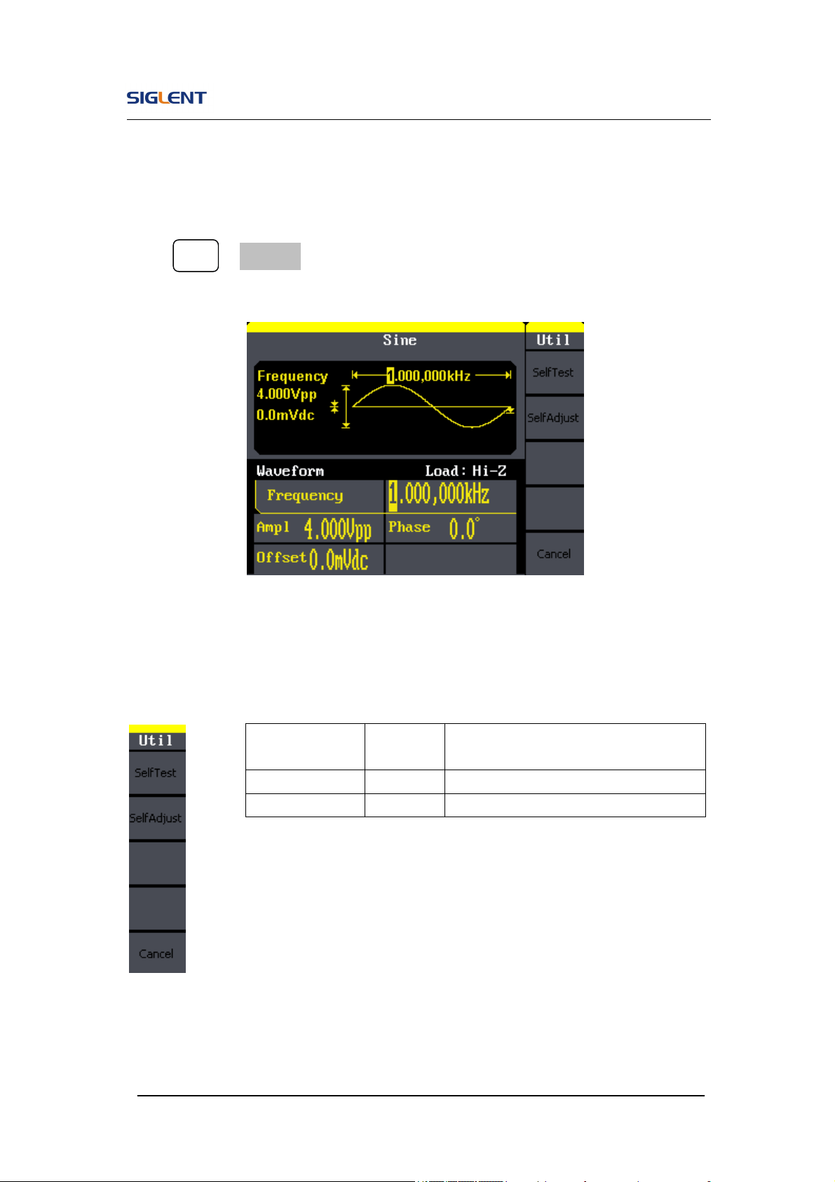
2.12. Test/Cal
Press Utility →Test/Cal, to enter the following menu.
Figure 2- 69 Test/Cal function Menu
Figure 2- 70 Table 2- 35 Menu Explanations of Test Setting
Function
Menu
Settings
Explain
SelfTest Perform system self-test.
SelfCal Do self calibration
SDG800 User Manual 75
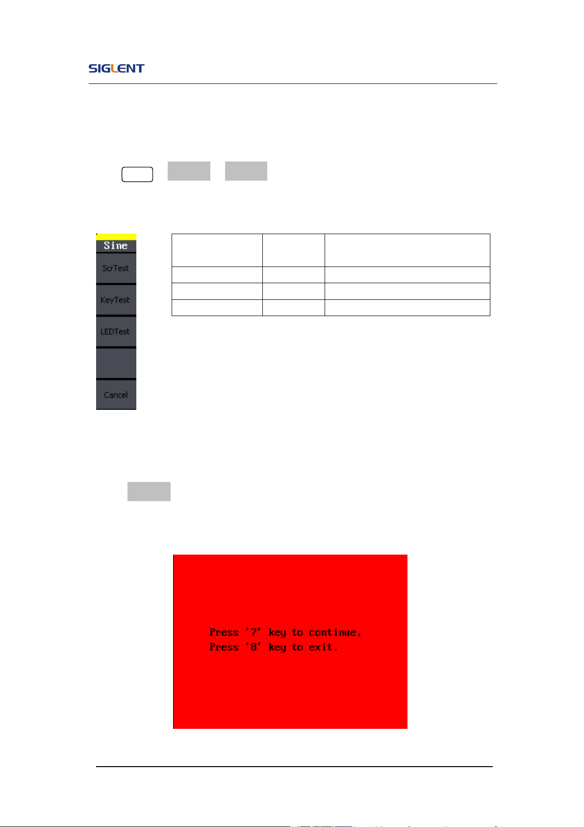
SelfTest
Press Utility →Test/Cal →SelfTest, to enter the following menu.
Figure 2- 71 Table 2- 36 Menu Explanations of Self Test
1. Scr Test
Select Scr Test to enter the screen test interface. The clew words ‘Press ‘7’
Key to continue, Press ‘8’ Key to exit’ is displayed. You could press the ‘7’ for
test.
Figure 2- 72 Screen Test Interface
Function
Menu
Settings Explain
Scr Test Run screen test program.
Key Test Run keyboard test program.
LED Test Run LED test program.
SDG800 User Manual 76
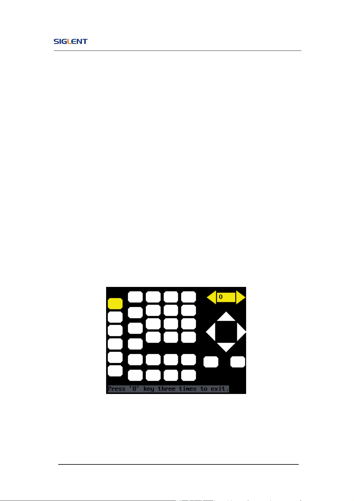
2. Key Test
Select ‘keyboard Test’ to enter the keyboard test interface, the on-screen
lathy rectangle shapes represent the front panel keys. The shapes with two
arrows beside them represent the front panel knobs. Test all keys and knobs
and you should also verify that all the backlit buttons illuminate correctly.
Note:
When you operate, the screen would display the white (color LCD).
The tested button or knobs corresponding area would display green
(color LCD).
At the bottom of the screen display ‘Press ‘8’ Key Three Times to
exit’ information prompt to show that press ‘8’ three times for
quitting the test.
Figure 2- 73 Key Test Interface
SDG800 User Manual 77
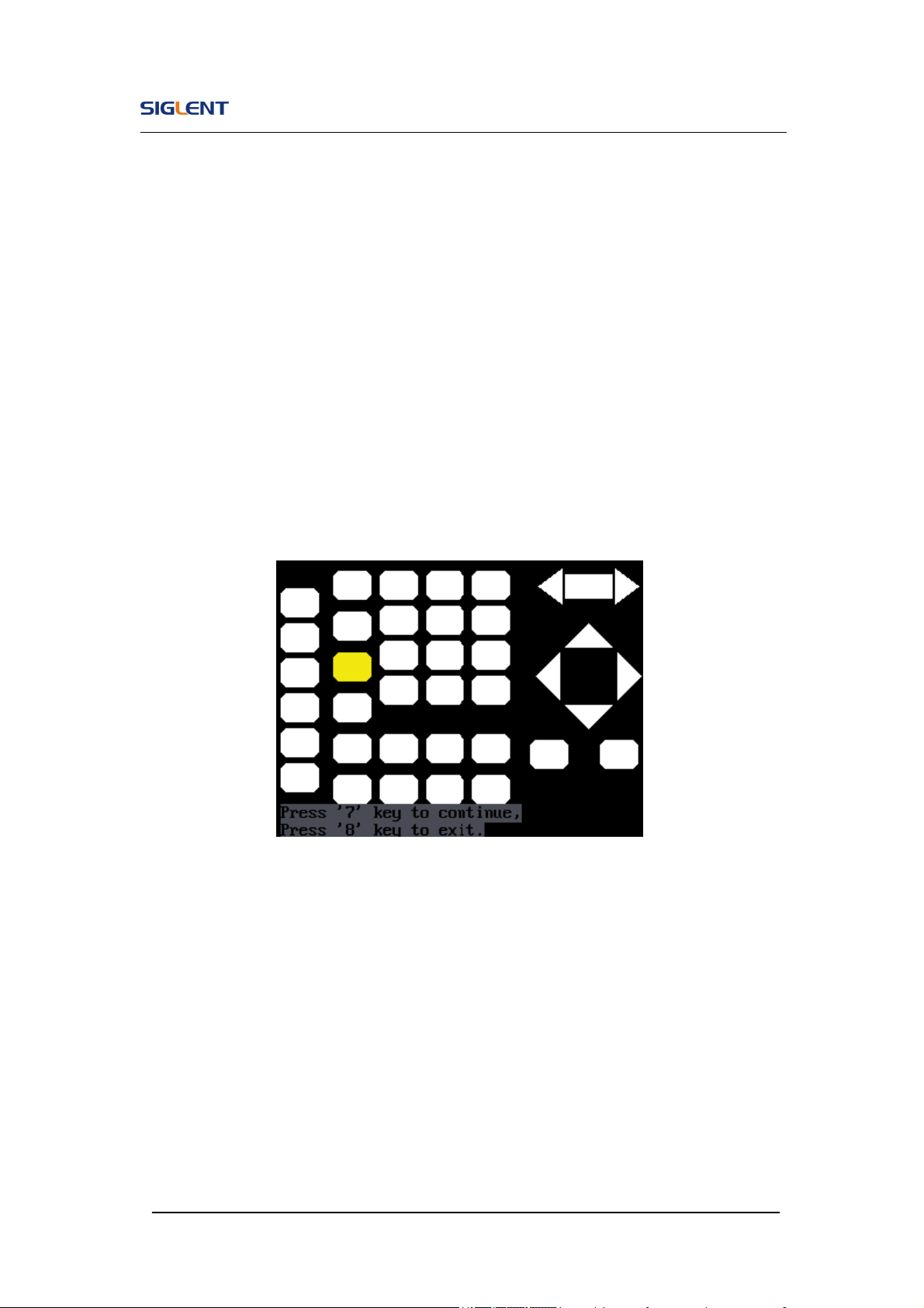
3. LED Test
Select ‘LED Test’ to enter the lighten interface, the on-screen lathy rectangle
shapes represent the front panel keys; the shapes with two arrows beside
them represent the front panel knobs. The clew words ‘Press ‘7’ Key to
continue, ‘Press ‘8’ Key to exit’ is displayed, You could press the ‘7’ button
continuously for testing, when buttons are lighted ,the corresponding area on
the screen would display green(color LCD).
Figure 2- 74 Led Test Interface
SDG800 User Manual 78
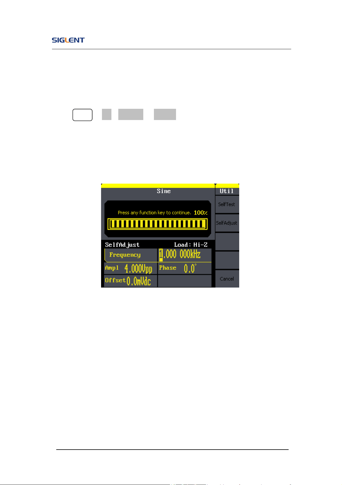
SelfCal
Press Utility →1/2→Test/Cal →SelfCal, to enter SelfCal, as is shown in
Figure 2- 5
SelfCal: do self calibration, environment you use the generator changes,
system may calibrate data based on change of current environment
Figure 2- 75 SelfCal Interface
SDG800 User Manual 79
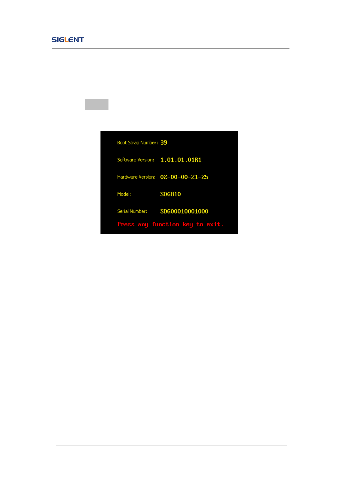
2.13. Edition Information
Press the EditInfo option button of the Utility Menu to view the generator’s
hardware and software configuration.
Figure 2- 76 Edit Info Interface
Edition Information introduce
Boot-strap No:
The times of boot-strap
Software version:
Software version of current equipment
Hardware version:
02-00-00-21-25 represents ordinally: PCB version, BOM version, Daughter
card version, FPGA version, CPLD version.
Model:
Contains information of brand of product, series, bandwidth.
For example: SDG810 represents SIGLENT’s 800 series function/arbitrary

SDG800 User Manual 80
waveform generator, the bandwidth is 10MHz.
Serial No:
Bit 1-6 represent maker and series of the product. Bit 7-10 represent
production date. Bit 11-14 represent serial number of product.
For example: SDG00004130008 represents the eighth generator made by
SIGLENT in the fourth quarter of 2013.

SDG800 User Manual 81
2.14. Updating Firmware
Using USB flash drive update firmware
The software of the generator can be updated directly via USB flash drive.
This process takes about two minutes. Follow the next steps:
1. Insert USB flash drive with firmware procedure to USB host interface on
the front panel of the generator.
2. Press the Utility button to enter the ‘Utility Menu’.
3. Press ‘1/2↓’ option button to enter the second page of ‘Utility Menu’.
4. Press the ‘Update’ option button.
5. Press ‘Brower’ option button to select ‘Directory’, then select the ‘USB
Device (A:)’ through direction key.
6. Press ‘Brower’ option button to select ‘File’, then select the ‘XXXX.ADS’
file by direction key.
7. Press the ‘Recall’ option button to updating.
8. After accomplish update, restart the generator.
Note: Don’t cut off the power during product is being updating.
SDG800 User Manual 82
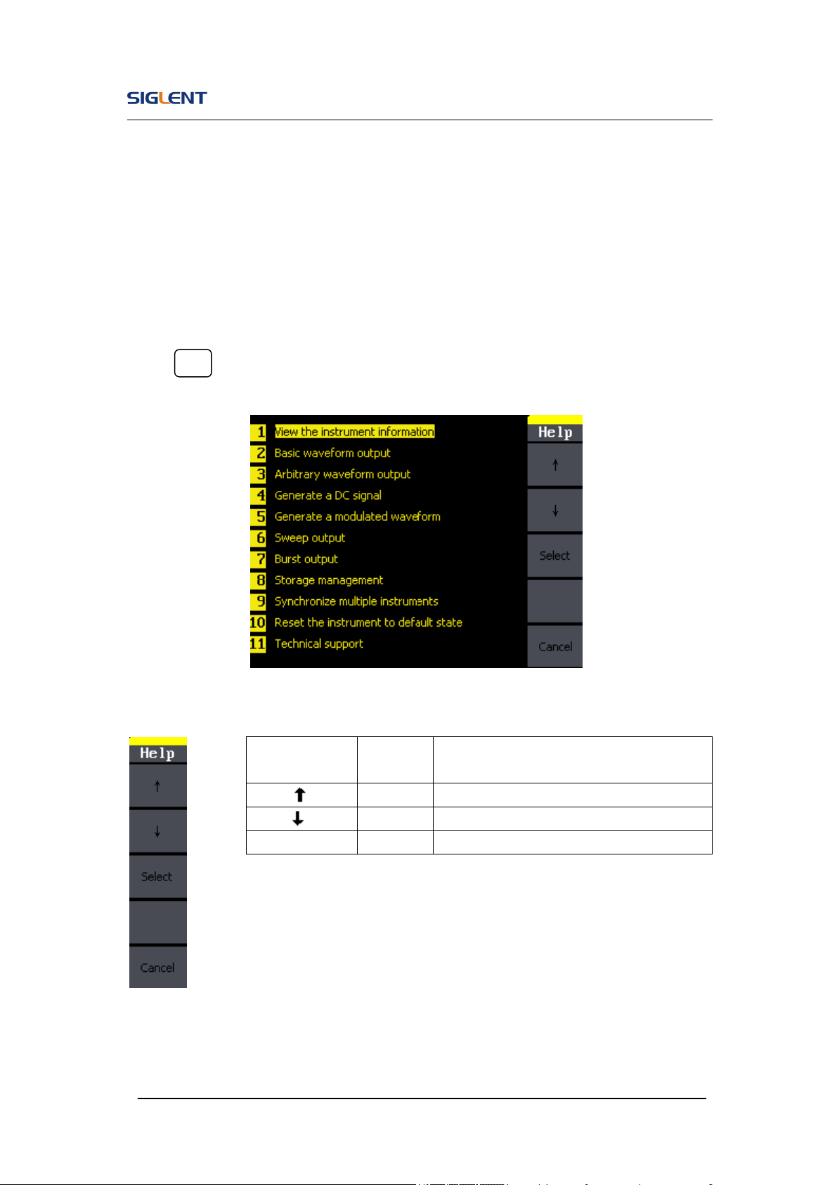
2.15. How to Use the Built-in Help System
You can get a particularly help for every button on the front panel by using the
built-in help system. Or you can get help about the operation of the front
panel buttons with the help list.
Press Help to enter the following interface.
Figure 2- 77 Help Menu
Figure 2- 78 Table 2- 37 Help Menu Explanations
Function
Menu
Settings
Explanation
Cursor upward to select.
Cursor downward to select.
Choice Select to read the information.

SDG800 User Manual 83
3. Application and Examples
To help the user master how to use the Function/ Arbitrary Waveform
Generator more efficiently, we will describe some examples in detail. All the
examples below use the default setting of the instrument except especial
explanations.
This chapter includes the following topics:
Example 1: Generate a Sine Wave
Example 2: Generate a Square Wave
Example 3: Generate a Ramp Wave
Example 4: Generate a Pulse Wave
Example 5: Generate a Noise Wave
Example 6: Generate an Arbitrary Wave
Example 7: Generate a Sweep Wave
Example 8: Generate a Burst Wave
Example 9: Generate an AM Wave
Example 10:Generate a FM Wave
Example 11:Generate a PM Wave
Example 12:Generate a FSK Wave
Example 13:Generate an ASK Wave
Example 14:Generate a PWM Wave
Example 15:Generate a DSB-AM Wave

SDG800 User Manual 84
3.1. Example 1:Generate a Sine Wave
Generate a sine wave with 50kHz frequency, 5Vpp amplitude and 1Vdc
offset.
Steps:
Set the frequency.
1. Press Sine →Freq and choose frequency which will display in white color.
2. Input ‘50’ from the keyboard and choose the unit ‘kHz’. The frequency is
set to be 50kHz.
Set the amplitude.
1. Press Ampl to choose Ampl which will display in white color.
2. Input ‘5’ from the keyboard and choose the unit ‘Vpp’. The amplitude is
set to be 5Vpp.
Set the Offset.
1. Press Offset to choose Offset which will display in white color
2. Input ‘1’ from the keyboard and choose the unit ‘Vdc’. The offset is set to
be 1Vdc.
When the frequency, amplitude and offset are set, the wave generated is
shown in Figure 3- 1;
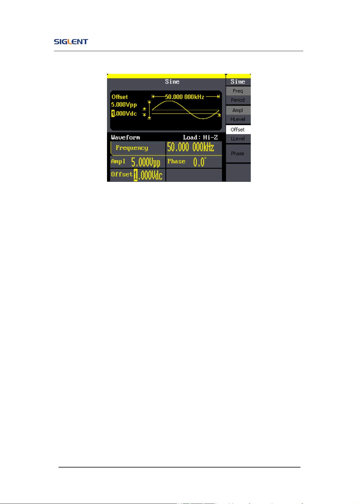
SDG800 User Manual 85
Figure 3- 1 Sine Waveform
SDG800 User Manual 86
3.2. Example 2:Generate a Square Wave
Generate a square wave with 5kHz frequency, 2Vpp amplitude, 0Vdc offset
and 30% duty cycle.
Steps:
Set the frequency.
1. Press Square →Freq and choose Frequency which will display in white
color.
2. Input ‘5’ from the keyboard and choose the unit ‘kHz’. The frequency is
set to be 5kHz.
Set the amplitude.
1. Press Ampl to choose Ampl which will display in white color.
2. Input ‘2’ from the keyboard and choose the unit ‘Vpp’. The amplitude is
set to be 2Vpp.
Set the offset.
1. Press Offset to choose Offset which will display in white color
2. Input ‘0’ from the keyboard and choose the unit ‘Vdc’. The Offset is set to
be 0Vdc.
Set the duty
1. Press Duty to choose Duty which will display in white color
2. Input ‘30’ from the keyboard and choose the unit ‘%’. The duty is set to be
30%.
When the frequency, amplitude, offset and duty cycle are set, the wave
generated is shown in Figure 3- 2.
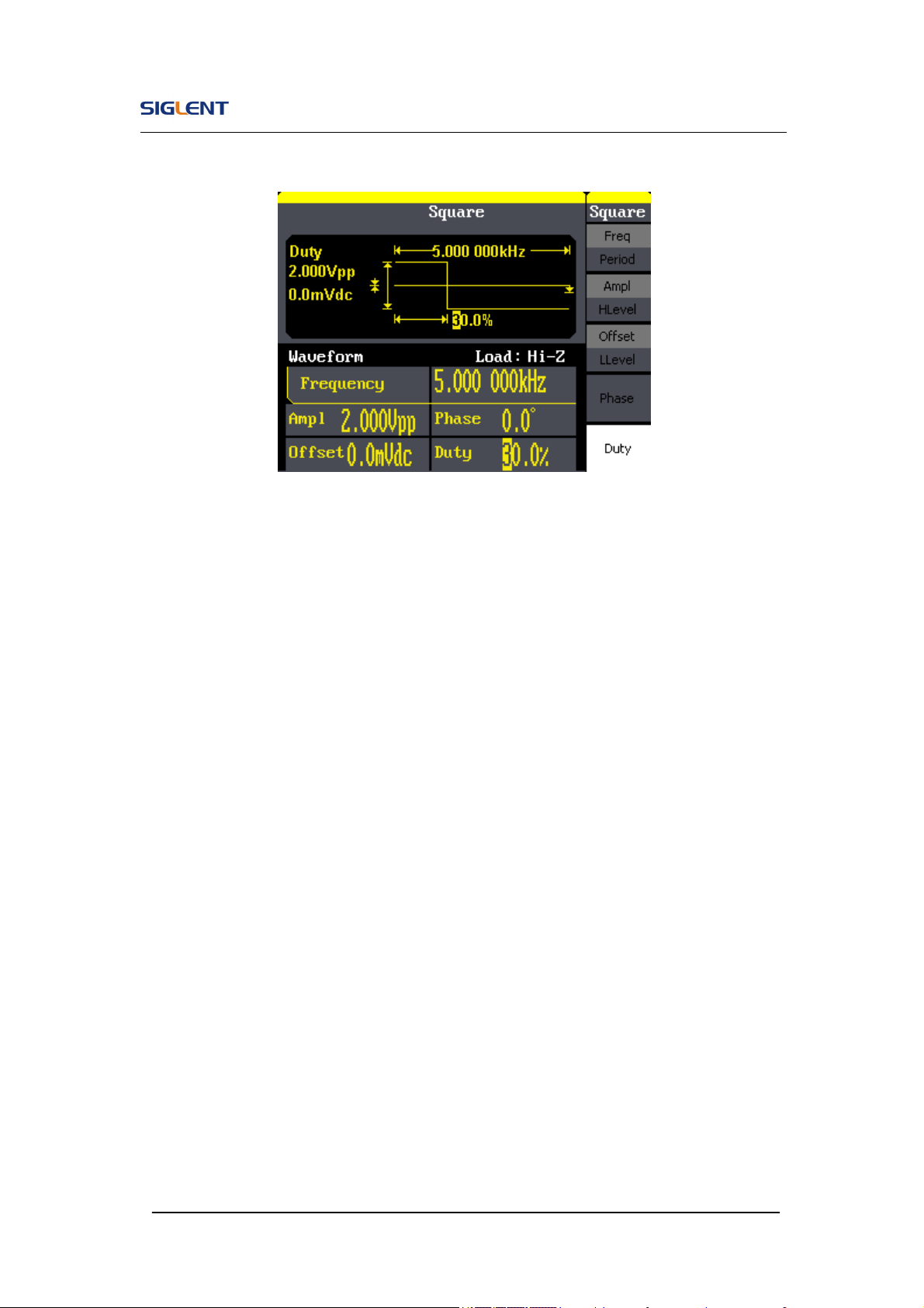
SDG800 User Manual 87
Figure 3- 2 Square Waveform

SDG800 User Manual 88
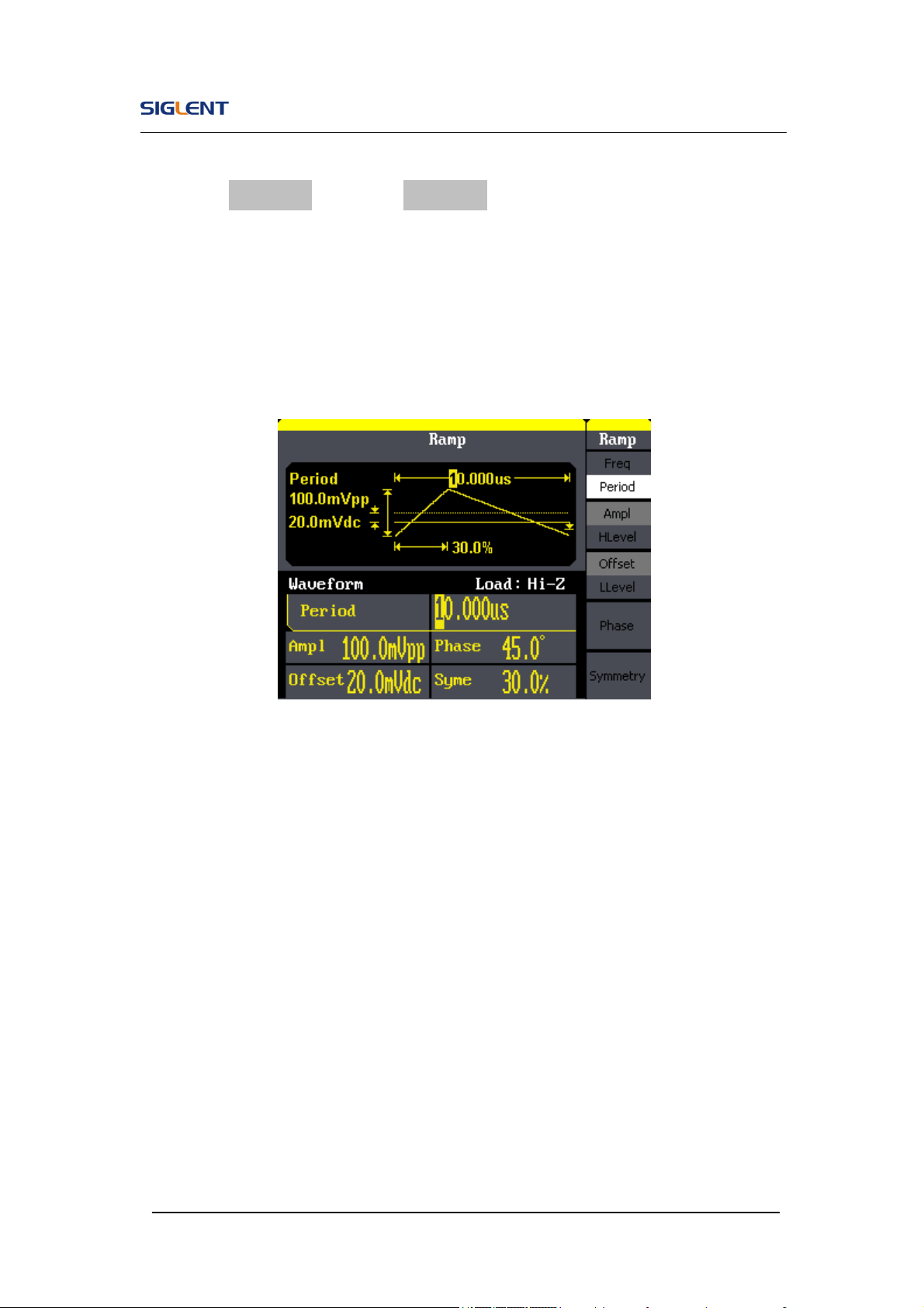
3.3. Example 3:Generate a Ramp Wave
Generate a ramp wave with 10μs period, 100mVpp amplitude, 20mVdc offset,
45°phase and 30% symmetry.
Steps:
Set the period.
1. Press Ramp →Freq and choose Period which will display in white color.
2. Input ‘10’ from the keyboard and choose the unit ‘μs’. The period is set to
be 10μs.
Set the amplitude.
1. Press Ampl to choose Ampl which will display in white color.
2. Input ‘100’ from the keyboard and choose the unit ‘mVpp’. The amplitude
is set to be 100mVpp.
Set the offset.
1. Press Offset to choose Offset which will display in white color
2. Input ‘20’ from the keyboard and choose the unit ‘mVdc’. The offset is set
to be 20mVdc.
Set the phase
1. Press Phase to choose Phase which will display in white color
2. Input ‘45’ from the keyboard and choose the unit ‘ °’. The phase is set to
be 45°.
SDG800 User Manual 89
Set the symmetry
1. Press Symmetry to choose Symmetry which will display in white color.
2. Input ‘30’ from the keyboard and choose the unit ‘30%’. The symmetry is
set to be 30%.
When the period, amplitude, offset, phase and symmetry are set, the wave
generated is shown in Figure 3- 3:
Figure 3- 3 Ramp Waveform

SDG800 User Manual 90
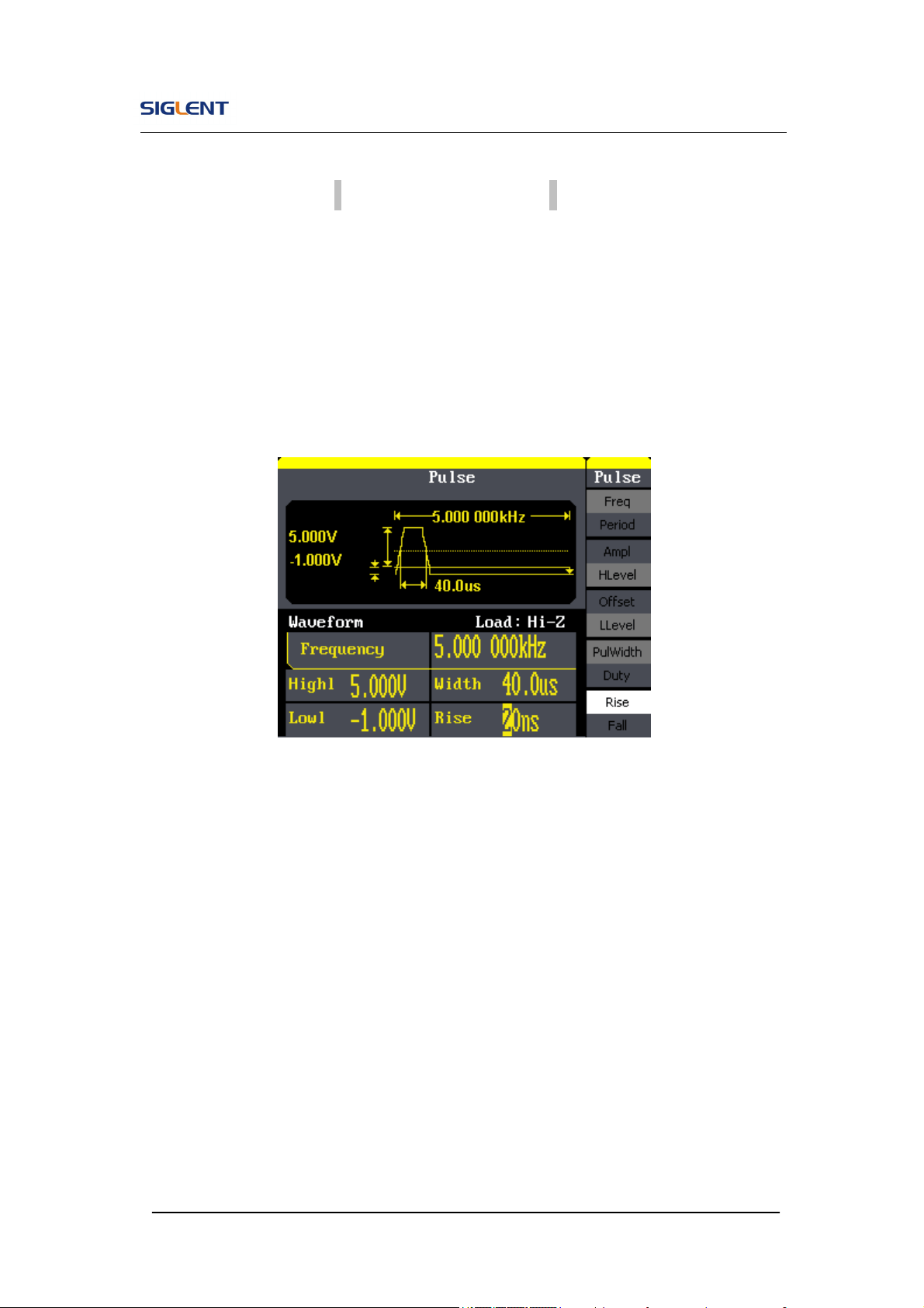
3.4. Example 4:Generate a Pulse Wave
Generate a pulse wave with 5kHz frequency, 5V high level, -1V low level,
40μs pulse width and 20ns delay.
Steps:
Set the frequency.
1. Press Pulse → Freq and choose Freq, which will display in white color.
2. Input ‘5’ from the keyboard and choose the unit ‘kHz’. The frequency is
set to be 5 kHz.
Set the high level
1. Press Ampl and choose the HLevel which will display in white color.
2. Input ‘5’ from the keyboard and choose the unit ‘V’. The high level is set
to be 5V.
Set the low level
1. Press Offset and choose the LLevel which will display in white color.
2. Input ‘-1’ from the keyboard and choose the unit ‘V’. The low level is set to
be -1V.
Set the pulse width
1. Press PulWidth and choose PulWidth which will display in white color.
2. Input ‘40’ from the keyboard and choose the unit ‘μs’. The pulse width is
set to be 40μs.
SDG800 User Manual 91
Set the Rising Edge
1. Press Rising Edge and choose Rising Edge which will display in white
color.
2. Input ‘20’ from the keyboard and choose the unit ‘ns’. The delay is set to
be 20ns.
When the frequency, high level, low level, pulse width and delay are set, the
wave generated is shown in Figure 3- 4
Figure 3- 4 Pulse Waveform
SDG800 User Manual 92
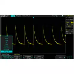
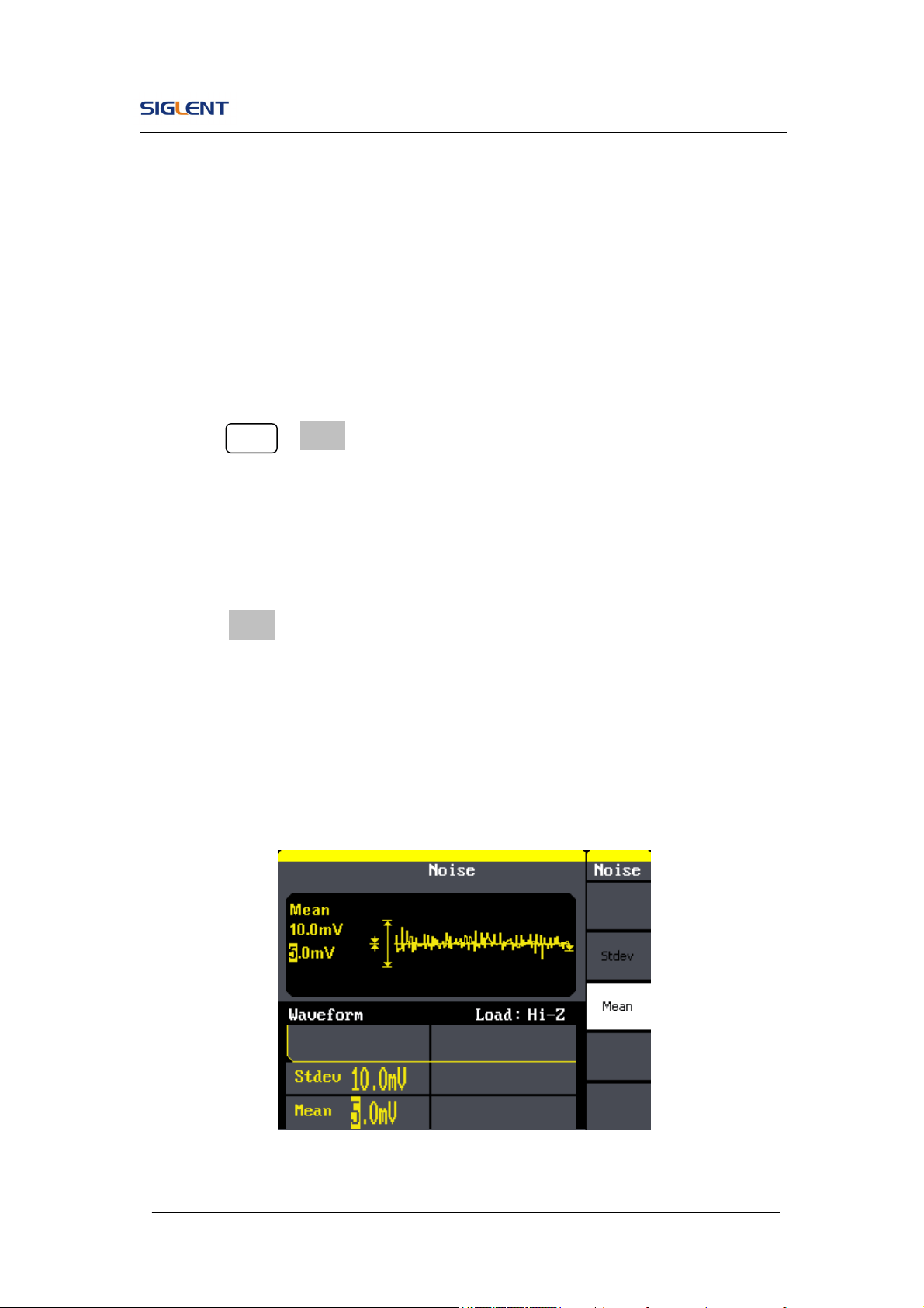
3.5. Example 5:Generate a Noise Wave
Generate a noise waveform with 2V stdev and 1 V mean.
Steps:
Set the stdev
1. Press Noise →Stdev.
2. Input ‘10’ from the keyboard and choose the unit ‘mV’. The amplitude is
set to be 10 mV.
Set the mean
1. Press Mean.
2. Input ‘5’ from the keyboard and choose the unit ‘mV’. The offset is set to
be 5 mV.
When the amplitude and offset are set, the wave generated is shown in
Figure 3- 5
Figure 3- 5 Noise Waveform

SDG800 User Manual 93
3.6. Example 6:Generate an Arbitrary Wave
Generate an arbitrary waveform (Sinc) with 5MHz frequency, 2Vrms
amplitude and 0Vdc offset.
Steps:
Set the type of the arbitrary waveform.
1. Press Arb → (1/2↓) →Load form, to choose the built-in waveform..
2. Press Built-In→ Math, There are sixteen math arbitrary waveforms.
3. Choose Sinc, and press Select to enter Arb Main Menu.
Set the frequency.
1. Press Freq and choose Frequency which will display in white color.
2. Input ‘5’ from the keyboard and choose the unit ‘MHz’. The frequency is
set to be 5MHz.
Set the amplitude
1. Press Ampl to choose Ampl which will display in white color.
2. Input ‘2’ from the keyboard and choose the unit ‘Vrms’. The amplitude is
set to be 2Vrms.
Set the offset
1. Press Offset to choose Offset which will display in white color.
2. Input ‘0’ from the keyboard and choose the unit ‘Vdc’. The offset is set to
be 0Vdc.
When the arbitrary waveform’s type, frequency, amplitude and offset are set,
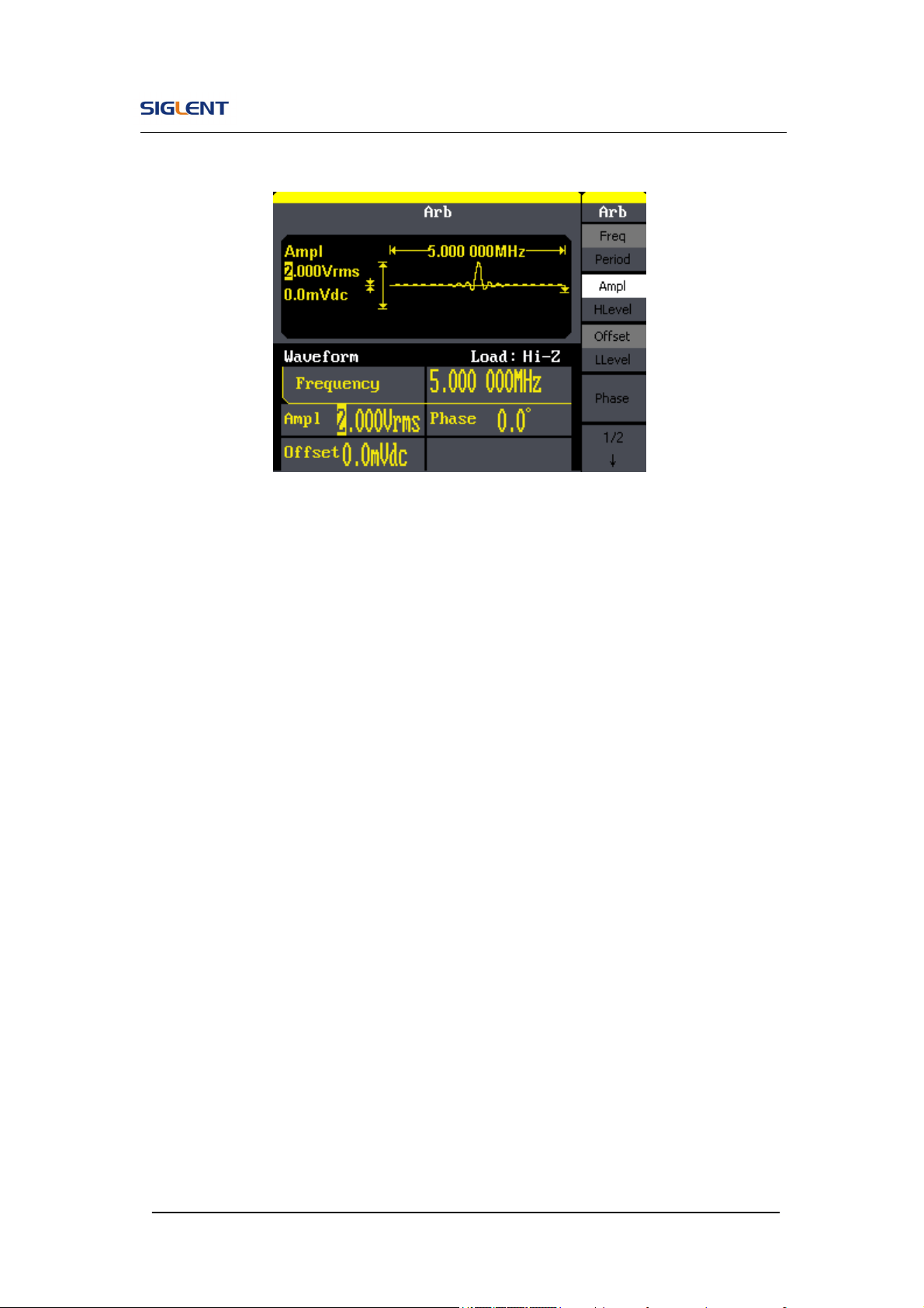
SDG800 User Manual 94
the wave generated is shown in Figure 3- 6:
Figure 3- 6 Sinc Waveform
SDG800 User Manual 95
3.7. Example 7:Generate a Sweep Linear Wave
Generate a sine sweep waveform whose frequency starts from 100Hz to
10kHz. Use internal trigger mode, linear sweep, and the sweep time is 2s.
Steps:
Set the sweep function:
Press Sine and choose the sine waveform as the sweep function.
The default setting of the source is internal.
Set the frequency, amplitude and offset.
1. Press Freq and choose Freq which will display in white color. Input ‘5’
from the keyboard and choose the unit ‘kHz’ to set the frequency 5kHz.
2. Press Ampl to choose Ampl which will display in white color. Input ‘5’ from
the keyboard and choose the unit ‘Vpp’ to set the amplitude 5Vpp.
3. Press Offset to choose Offset which will display in white color. Input ‘0’
from the keyboard and choose the unit ‘Vdc’ to set the offset 0Vdc
Set the sweep time.
Press Sweep →Sweep Time, Input ‘2’ from the keyboard and choose the
unit ‘s’ to set sweep time 2s.
Set the start frequency
Press Start Freq, Input ‘100’ from the keyboard and choose the unit ‘Hz’
to set start freq 100Hz.
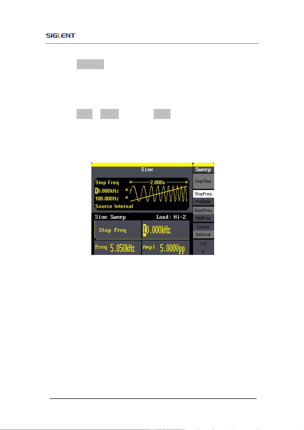
SDG800 User Manual 96
Set the end frequency
Press Stop Freq, Input ‘10’ from the keyboard and choose the unit ‘kHz’
to set stop freq 10kHz.
Set the Sweep Mode
Press (1/2↓) →Linear, and choose Linear.
When all parameters above are set, the linear sweep wave generated is
shown in Figure 3- 7
Figure 3- 7 Sweep Waveform
SDG800 User Manual 97
3.8. Example 8:Generate a Burst Wave
Generate a burst waveform of 5 cycles. The period is 3ms. Use internal
trigger and 0 degree phase.
Steps:
Set the sweep function:
Press Sine, and choose the sine waveform as the burst function. The
default setting of the source is internal.
Set the frequency, amplitude and offset
1. Press Freq and choose Freq which will display in white color. Input ‘10’
from the keyboard and choose the unit ‘kHz’ to set the frequency 10kHz.
2. Press Ampl to choose Ampl which will display in white color. Input ‘1’ from
the keyboard and choose the unit ‘Vpp’ to set the amplitude 1Vpp.
3. Press Offset to choose Offset which will display in white color. Input ‘0’
from the keyboard and choose the unit ‘Vdc’ to set the offset 0Vdc
Set the sweep mode.
Press Burst →N Cycle, choose N Cycle Mode.
Set the burst period
Press Period, input ‘3’ from the keyboard and choose the unit ‘ms’ to set
the period 3ms.
Set the start phase
Press Start Phase, input ‘0’ from the keyboard and choose the unit ‘ °’ to
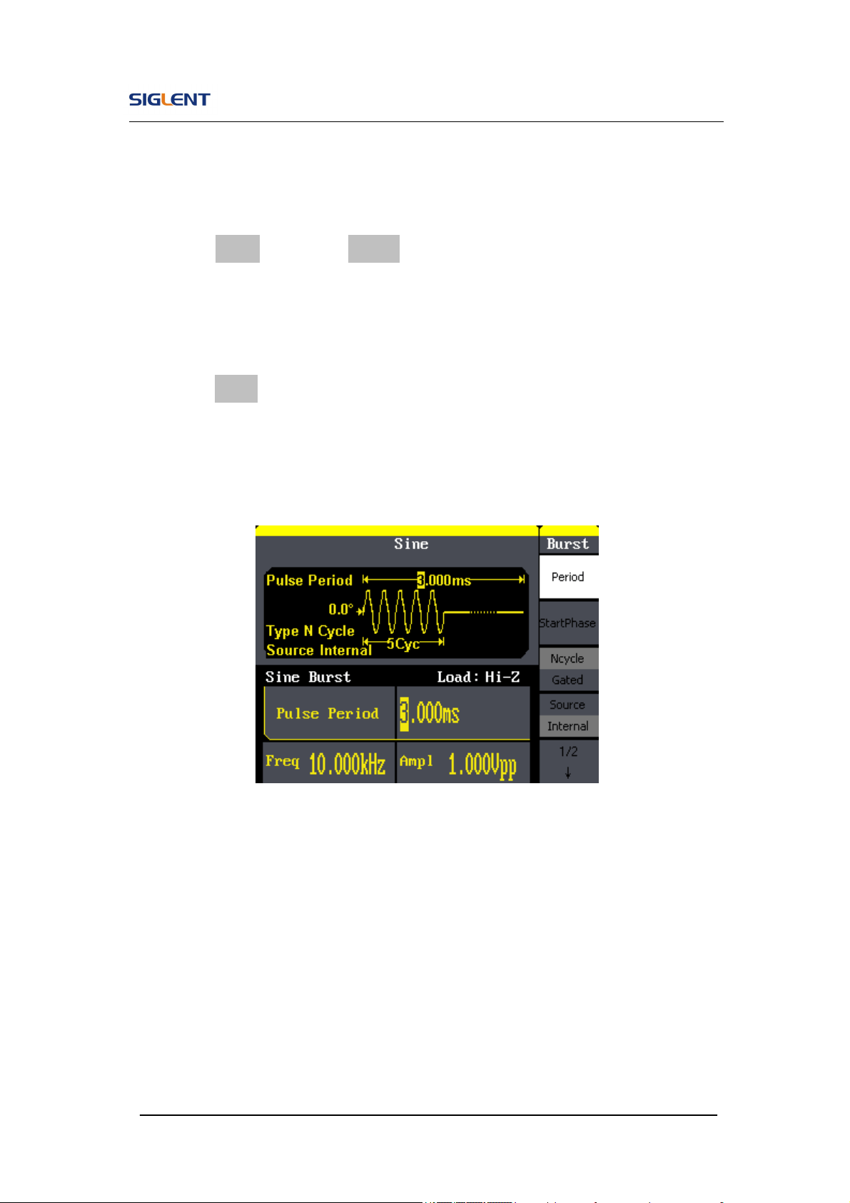
SDG800 User Manual 98
set the start phase 0°.
Set the burst cycles
Press (1/2↓) →Choose Cycles, Input ‘5’ from the keyboard and choose
the unit ‘Cycle’ to set the burst cycle 5.
Set the delay
Press Delay, and input ‘100’ from the keyboard and choose the unit ‘μs’
to set the delay 100μs.
When all parameters above are set, the wave generated is shown in Figure
3- 8:
Figure 3- 8 Burst Waveform Output
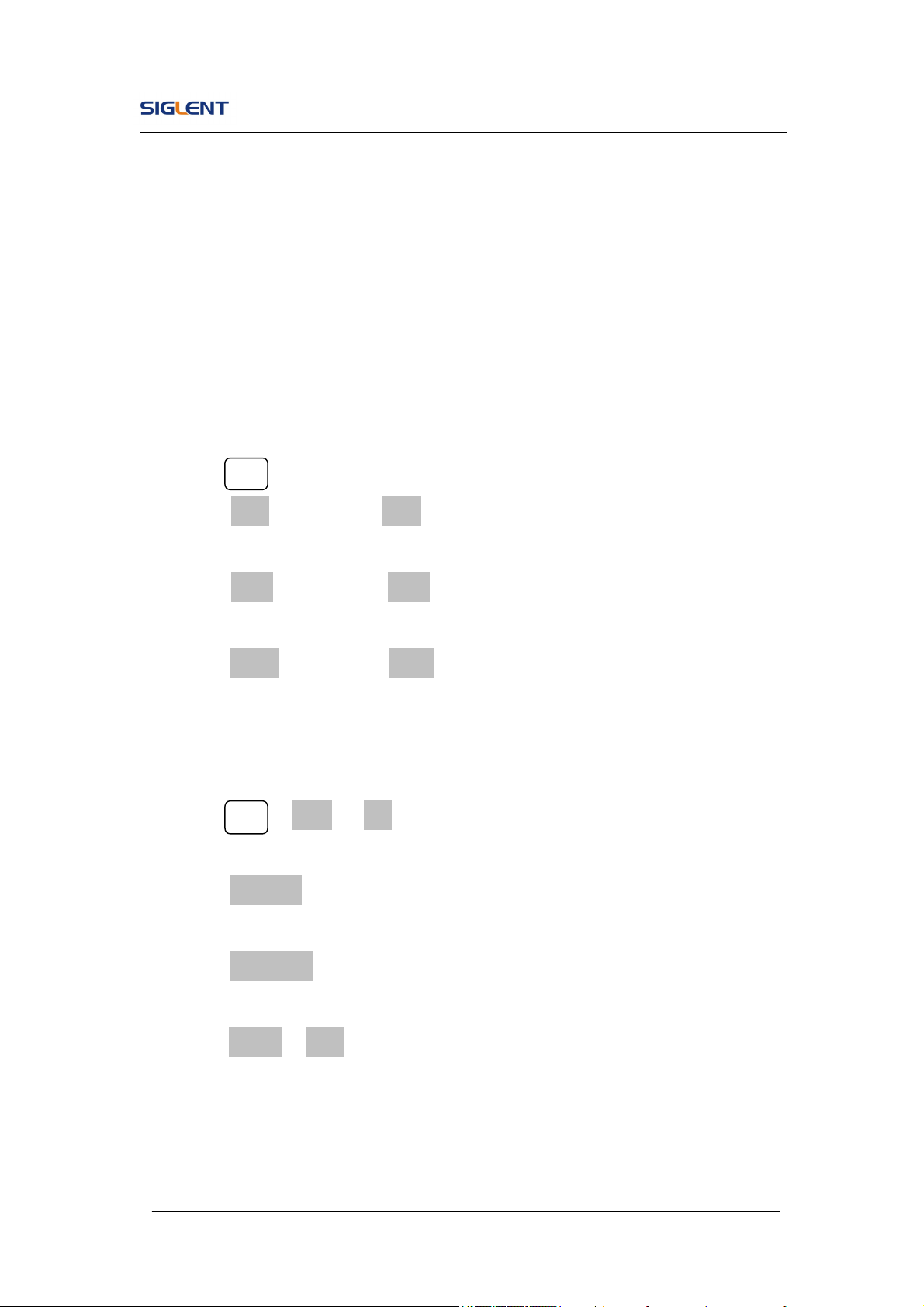
SDG800 User Manual 99
3.9. Example 9:Generate an AM Wave
Generate an AM waveform with 80% depth. The carrier is a sine wave with
10kHz frequency, and the modulating wave is a sine wave with 200Hz
frequency.
Steps:
Set the frequency, amplitude and offset of the carrier wave.
1. Press Sine , and choose the sine waveform as the carrier wave
2. Press Freq and choose Freq which will display in white color. Input’10’
from the keyboard and choose the unit ‘kHz’ to set the frequency 10kHz
3. Press Ampl and choose Ampl which will display in white color. Input’1’
from the keyboard and choose the unit ‘Vpp’ to set the amplitude 1Vpp.
4. Press Offset and choose Offset which will display in white color. Input’0’
from the keyboard and choose the unit ‘Vdc’ to set the offset 0Vdc.
Set the modulation type AM and parameters.
1. Press Mod →Type → AM, choose AM. Please notice that the message
shown on the middle left side of the screen is ‘AM’.
2. Press AM Freq, input’200’ from the keyboard and choose the unit ‘Hz’ to
set the AM freq 200Hz.
3. Press AM Depth, input’80’ from the keyboard and choose the unit ‘%’ to
set the AM depth 80%.
4. Press Shape →Sine, to choose sine wave as the modulating waveform.
When all parameters above are set, the wave generated is shown in Figure
3- 9:
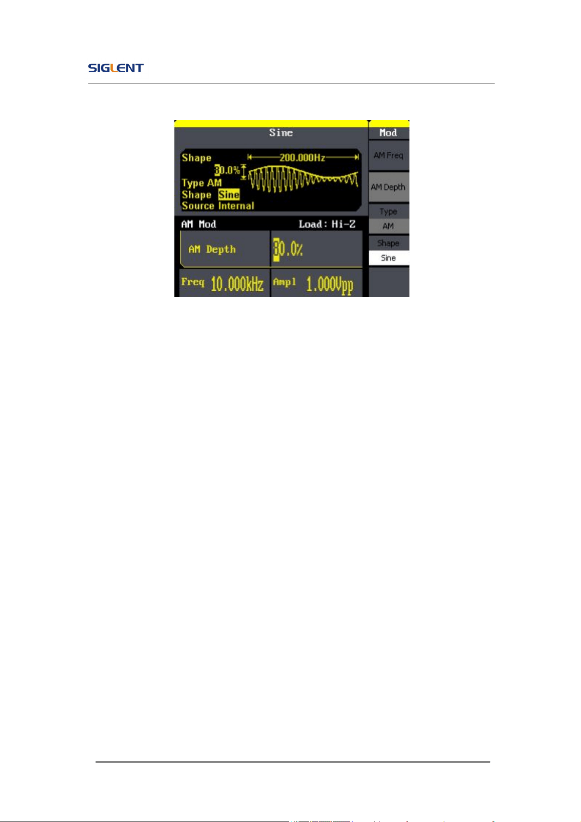
SDG800 User Manual 100
Figure 3- 9 AM Waveform

SDG800 User Manual 101
3.10. Example 10:Generate a FM Wave
Generate a FM waveform, the carrier is a sine wave with 10kHz frequency,
and the modulating wave is a sine wave with 1 Hz frequency, 2kHz frequency
deviation.
Steps:
Set the frequency, amplitude and offset of the carrier wave.
1. Press Sine and choose the sine waveform as the carrier wave
2. Press Freq and choose Freq which will display in white color. Input’10’
from the keyboard and choose the unit ‘kHz’ to set the frequency 10kHz
3. Press Ampl and choose Ampl which will display in white color. Input’1’
from the keyboard and choose the unit ‘Vpp’ to set the amplitude 1Vpp.
4. Press Offset and choose Offset which will display in white color. Input’0’
from the keyboard and choose the unit ‘Vdc’ to set the offset 0Vdc.
Set the modulation type FM and parameters.
1. Press Mod →Type → FM, choose FM. Please notice that the message
shown on the middle left side of the screen is ‘FM’.
2. Press FM Freq, input ‘1’ from the keyboard and choose the unit ‘Hz’ to set
the AM Freq 1Hz.
3. Press FM Dev, input ‘2’ from the keyboard and choose the unit ‘kHz’ to
set the FM deviation 2kHz.
4. Press Shape →Sine, to choose sine wave as the modulating waveform.
When all parameters above are set, the wave generated is shown in Figure
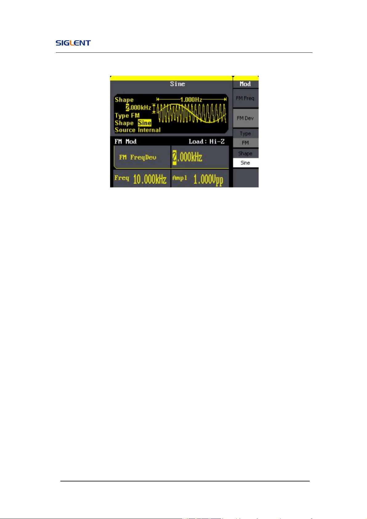
SDG800 User Manual 102
3- 10:
Figure 3- 10 FM Waveform

SDG800 User Manual 103
3.11. Example 11:Generate a PM Wave
Generate a PM waveform, the carrier is a sine wave with 10kHz frequency,
and the modulating wave is a sine wave with 2kHz frequency, 90°phase
deviation.
Steps:
Set the frequency, amplitude and offset of the carrier wave.
1. Press Sine , and choose the sine waveform as the carrier wave
2. Press Freq and choose Freq which will display in white color. Input’10’
from the keyboard and choose the unit ‘kHz’ to set the frequency 10kHz
3. Press Ampl and choose Ampl which will display in white color. Input’5’
from the keyboard and choose the unit ‘Vpp’ to set the amplitude 5Vpp.
4. Press Offset and choose Offset which will display in white color. Input’0’
from the keyboard and choose the unit ‘Vdc’ to set the offset 0Vdc.
Set the modulation type PM and parameters.
1. Press Mod →Type → PM, choose PM. Please notice that the message
shown on the middle left side of the screen is ‘PM’.
2. Press PM Freq, input ‘2’ from the keyboard and choose the unit ‘kHz’ to
set the PM freq 2kHz.
3. Press Phase Dev, input ‘90’ from the keyboard and choose the unit ‘ °’ to
set the phase deviation 90°.
4. Press Shape →Sine, to choose sine wave as the modulating waveform.
When all parameters above are set, the wave generated is shown in Figure
3- 11:
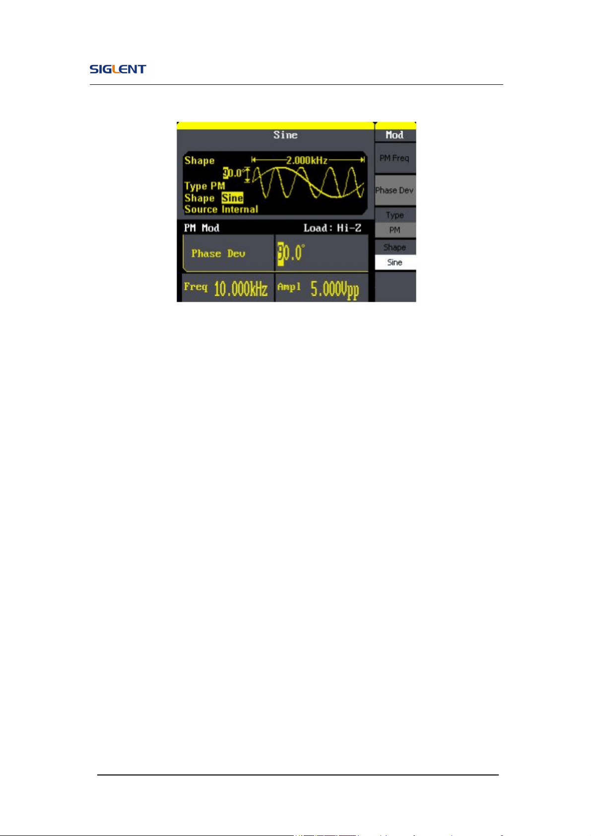
SDG800 User Manual 104
Figure 3- 11 PM Waveform
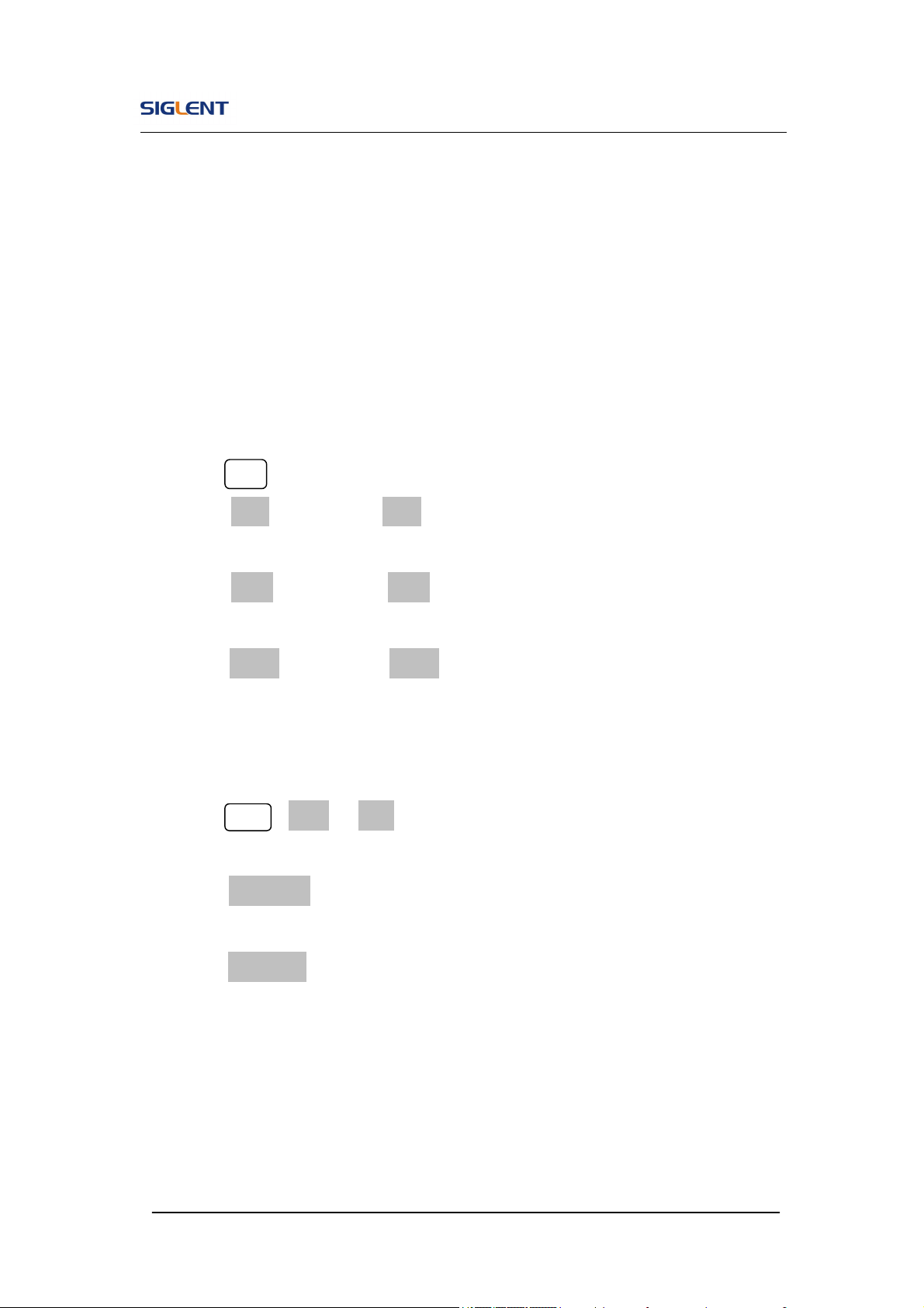
SDG800 User Manual 105
3.12. Example 12:Generate a FSK Wave
Generate a FSK waveform with 200Hz key frequency. The carrier is a sine
wave with 10kHz frequency, and the hop frequency is 500Hz.
Steps:
Set the frequency, amplitude and offset of the carrier wave.
1. Press Sine , and choose the sine waveform as the carrier wave
2. Press Freq and choose Freq which will display in white color. Input’10’
from the keyboard and choose the unit ‘kHz’ to set the frequency 10kHz
3. Press Ampl and choose Ampl which will display in white color. Input’5’
from the keyboard and choose the unit ‘Vpp’ to set the amplitude 5Vpp.
4. Press Offset and choose Offset which will display in white color. Input’0’
from the keyboard and choose the unit ‘Vdc’ to set the offset 0Vdc.
Set the modulation type FSK and parameters.
1. Press Mod →Type → FSK, choose FSK. Please notice that the message
shown on the middle left side of the screen is ‘FSK ’.
2. Press Key Freq, input’200’ from the keyboard and choose the unit ‘Hz’ to
set the key frequency 200 Hz.
3. Press Hop Freq, input ‘500’ from the keyboard and choose the unit ‘Hz’ to
set the hop frequency 500Hz.
When all parameters above are set, the wave generated is shown in Figure
3- 12:
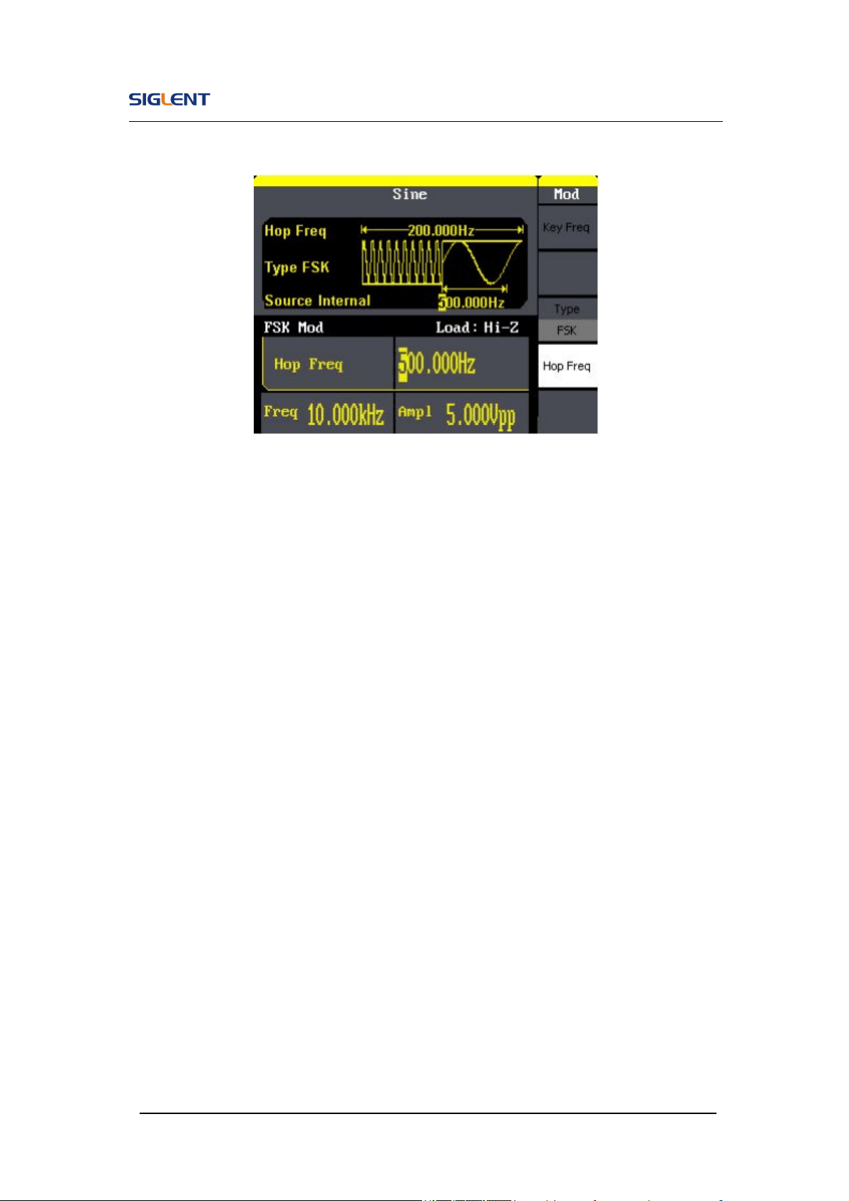
SDG800 User Manual 106
Figure 3- 12 FSK Waveform

SDG800 User Manual 107
3.13. Example 13:Generate an ASK Wave
Generate an ASK waveform with 500Hz key frequency. The carrier is a sine
wave with 5kHz frequency.
Steps:
Set the frequency, amplitude and offset of the carrier wave.
1. Press Sine , and choose the sine waveform as the carrier wave
2. Press Freq and choose Freq which will display in white color. Input ‘5’
from the keyboard and choose the unit ‘kHz’ to set the frequency 5kHz
3. Press Ampl and choose Ampl which will display in white color. Input ‘5’
from the keyboard and choose the unit ‘Vpp’ to set the amplitude 5Vpp.
4. Press Offset and choose Offset which will display in white color. Input ‘0’
from the keyboard and choose the unit ‘Vdc’ to set the offset 0Vdc.
Set the modulation type ASK and parameters.
1. Press Mod →Type → ASK, choose ASK. Please notice that the message
shown on the middle left side of the screen is ‘ASK ’.
2. Press Key Freq, input ‘500’ from the keyboard and choose the unit ‘Hz’ to
set the key freq 500 Hz.
When all parameters above are set, the wave generated is shown in Figure
3- 13
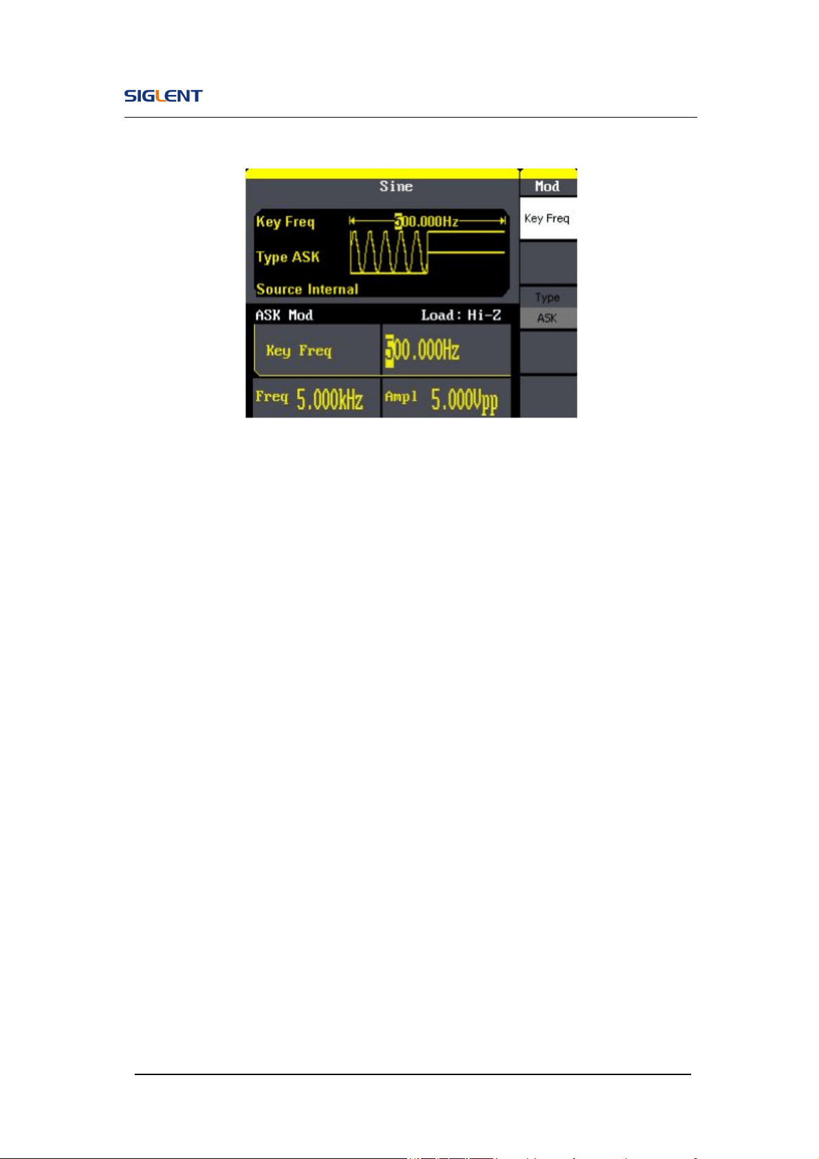
SDG800 User Manual 108
Figure 3- 13 ASK Waveform
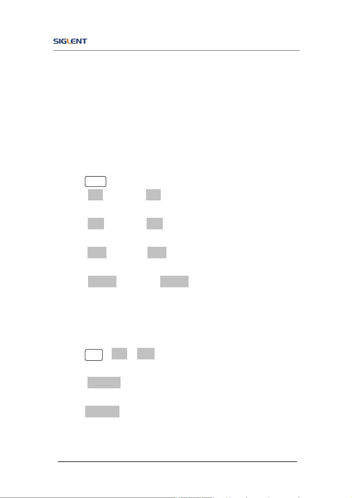
SDG800 User Manual 109
3.14. Example 14: Generate a PWM Wave
Generate a PWM waveform with 200Hz key frequency. The carrier is a pulse
wave with 5kHz frequency.
Steps:
Set the frequency, amplitude and offset of the carrier wave.
1. Press Pulse , and choose the Pulse waveform as the carrier wave
2. Press Freq and choose Freq which will display in white color. Input ‘5’
from the keyboard and choose the unit ‘kHz’ to set the frequency 5kHz
3. Press Ampl and choose Ampl which will display in white color. Input ‘5’
from the keyboard and choose the unit ‘Vpp’ to set the amplitude 5Vpp.
4. Press Offset and choose Offset which will display in white color. Input ‘0’
from the keyboard and choose the unit ‘Vdc’ to set the offset 0Vdc.
5. Press PulWidth and choose PulWidth which will display in white color.
Input ‘40’ from the keyboard and choose the unit ‘us’ to set the PulWidth
40us
Set the modulation type PWM and parameters.
1. Press Mod →Type →PWM, Please notice that the message shown on
the middle left side of the screen is ‘PWM ’.
2. Press PWN Freq, input ‘200’ from the keyboard and choose the unit ‘Hz’
to set the key freq 200 Hz.
3. Press Width Dev, input ‘20’ from the keyboard and choose the unit ‘us’ to
set the Width Dev 20us
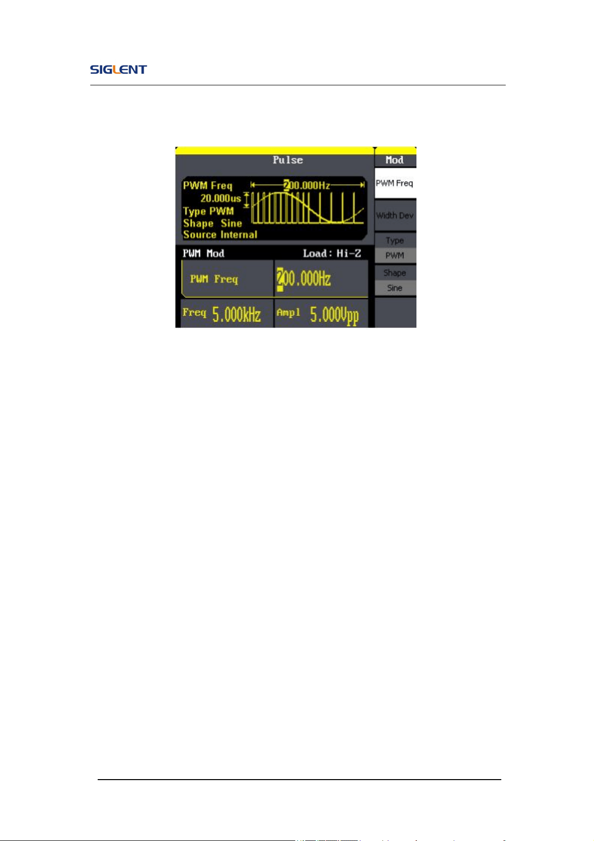
SDG800 User Manual 110
When all parameters above are set, the wave generated is shown in Figure
3- 14
Figure 3- 14 PWM Waveform

SDG800 User Manual 111
3.15. Example 15: Generate a DSB-AM Wave
Generate a DSB-AM waveform with 100Hz key frequency. The carrier is a
sine wave with 2kHz frequency.
Steps:
Set the frequency, amplitude and offset of the carrier wave.
1. Press Sine , and choose the sine waveform as the carrier wave
2. Press Freq and choose Freq which will display in white color. Input ‘2’
from the keyboard and choose the unit ‘kHz’ to set the frequency 2kHz
3. Press Ampl and choose Ampl which will display in white color. Input ‘4’
from the keyboard and choose the unit ‘Vpp’ to set the amplitude 4Vpp.
4. Press Offset and choose Offset which will display in white color. Input ‘0’
from the keyboard and choose the unit ‘Vdc’ to set the offset 0Vdc.
Set the modulation type DSB-AM and parameters.
1. Press Mod →Type →DSB-AM, choose DSB-AM. Please notice that the
message shown on the middle left side of the screen is ‘DSB-AM ’.
2. Press DSB Freq, input ‘100’ from the keyboard and choose the unit ‘Hz’
to set the key freq 100Hz.
When all parameters above are set, the wave generated is shown in Figure
3- 15
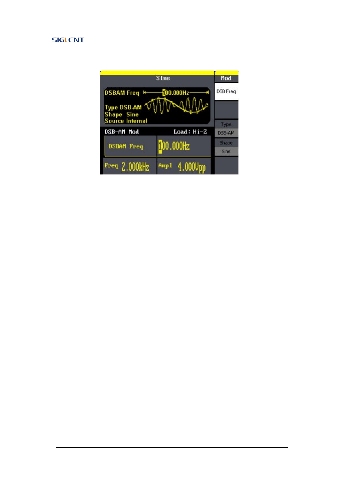
SDG800 User Manual 112
Figure 3- 15 DSB-AM Waveform

SDG800 User Manual 113
4. Troubleshooting
General Inspecting
After receiving a new SDG800 Series Function/Arbitrary Waveform
Generator, please inspect the instrument as followed:
1. Inspect the shipping container for damage.
Keep the damaged shipping container or cushioning material until the
contents of the shipment have been checked for completeness and the
instrument has been checked mechanically and electrically.
2. Inspect the whole instrument.
In case there is any mechanical damage or defect, or the instrument
does not operate properly or fails performance tests, notify the SIGLENT
sales representative.
If the shipping container is damaged, or the cushioning materials show
signs of stress, notify the carrier as well as the SIGLENT sales
department. Keep the shipping materials for carrier’s inspection.
3. Check the accessories.
Accessories supplied with the instrument are listed below. If the contents
are incomplete or damaged, notify the SIGLENT sales representative.
Standard Accessories:
A Q uick Start
A Certification and Guaranty Card
A CD(including EasyWave computer software system)
A Power Cord that fits the standard of destination country
A USB Cable

SDG800 User Manual 114
Troubleshooting
1. After the waveform generator is powered on, the screen remains
dark, please do the following steps:
(1) Check the power cable’s connection.
(2) Ensure the power switch is turned on.
(3) After the inspections above, restart the waveform generator.
(4) If the generator still doesn’t work after the checking, please connect
with SIGLENT company
2. If there is no signal wave output after setting the parameters, please
do as following steps:
(1) Check whether the BNC cable has connected with output channel or not.
(2) Check whether the output button have been turned on or not.

SDG800 User Manual 115
5. Service and Support
Maintain summary
SIGLENT warrants that the products that it manufactures and sells will be
free from defects in materials and workmanship for a period of three years
from the date of shipment from an authorized SIGLENT distributor. If a
product proves defective within the respective period, SIGLENT will provide
repair or replacement as described in the complete warranty statement.
To arrange for service or obtain a copy of the complete warranty statement,
please contact your nearest SIGLENT sales and service office.
Except as provided in this summary or the applicable warranty statement,
SIGLENT makes no warranty of any kind, express or implied, including
without limitation the implied warranties of merchantability and fitness for a
particular purpose. In no event shall SIGLENT be liable for indirect, special or
consequential damages

SDG800 User Manual 116
Contact SIGLENT
MTR Add: 3/F, Building 4, Antongda Industrial Zone, Liuxian Road,
68 District, Baoan District, Shenzhen, P.R. CHINA
Service Tel: 0086 755 3661-5186
Post Code: 518101
E-mail:sales@siglent.com
http://www.siglent.com

SDG800 User Manual 117
6. Appendix
Appendix A: Accessories
SDG800 Series Function/ Arbitrary Waveform Generator Accessories:
Standard Accessories:
A Quick Start
A Calibration Certificate
A CD(including EasyWave computer software system)
A Power Cord that fits the standard of destination country
A USB Cable
SDG800 User Manual 118
Appendix B: Daily Maintain and Cleaning
Daily Maintain
Do not store or leave the instrument in where the LCD will be exposed to
direct sunlight for long periods of time.
CAUTION: To avoid damage to the instrument, do not expose them
to sprays, liquids, or solvents.
Cleaning
If this instrument requires cleaning, disconnect it from all power sources and
clean it with a mid detergent and water. Make sure the instrument is
completely dry before reconnecting it to a power source.
To clean the exterior surface, perform the following steps:
1. Remove loose dust on the outside of the instrument with a lint-free
cloth. Use care to avoid scratching the clear plastic display filter.
2. Use a soft cloth dampened with water to clean the instrument.
WARNING: To avoid damage to the surface of the instrument, do
not use any abrasive or chimerical cleaning agents.

Quick Start
SDG800 Series
Function/Arbitrary Waveform Generator
2014 SIGLENT TECHNOLOGIES CO., LTD
QS02008-E02A


SIGLENT
SDG800 Quick Start I
Copyright
● SIGLENT TECHNOLOGIES CO., LTD. All rights reserved.
● The information provided in this manual replaces all information
printed before.
● SIGLENT Company has the rights to change the specification and the
price.
● Contents in this manual are not allowed to be copied, extracted and
translated without permission by the company.

SIGLENT
II SDG800 Quick Start
General Safety Summary
Carefully read the following safety precautions to avoid person injury and
prevent damage to the instrument and any products connected to it. To avoid
potential hazards, please use the instrument as specified.
Only qualified technician should perform service procedures
To Avoid Fire or Personal Injure
Use Proper Power Line
Use only the special power line of the instrument which approved by local
state.
Ground the Instrument
The instrument grounds through the protective terra conductor of the power
line. To avoid electric shock, the ground conductor must be connected to the
earth. Make sure the instrument is grounded correctly before connect its input
or output terminals.
Connect the Signal Wire Correctly
The potential of the signal wire is equal to the earth, so do not connect the
signal wire to a high voltage. Do not touch the exposed contacts or
components.
Look Over All Terminals’ Ratings
To avoid fire or electric shock, please look over all ratings and sign instruction
of the instrument. Before connecting the instrument, please read the manual
carefully to gain more information about the ratings.
Not Operate with Suspected Failures
If you suspect that there is a damage of the instrument, please let a qualified
service personnel check it.
Avoid Circuit or Wire Exposed Components Exposed
Do not touch exposed contacts or components when the power is on.
Do not operate in wet/damp conditions.
Do not operate in an explosive atmosphere.
Keep the surface of the instrument clean and dry.
SIGLENT
SDG800 Quick Start III
Safety Terms and Symbols
Terms used on the instrument. Terms may appear on the instrument:
DANGER: Indicates an injury or hazard that may be immediately happen.
WARNING: Indicates an injury or hazard that may be not immediately happen.
CAUTIO: Indicates that a potential damage to the instrument or other property
might occur.
Symbols used on the instrument. Symbols may appear on the instrument:
Hazardous Protective Warning Earth Ground Power
Voltage Earth Ground Switch

SIGLENT
IV SDG800 Quick Start
Content
General Safety Summary.......................................................................................II
Adjustment Handle.................................................................................................. 1
The Front Panel ...................................................................................................... 2
Back Panel............................................................................................................... 6
User Interface.......................................................................................................... 7
Using In-line Help System...................................................................................... 9
Contact SIGLENT ................................................................................................. 10
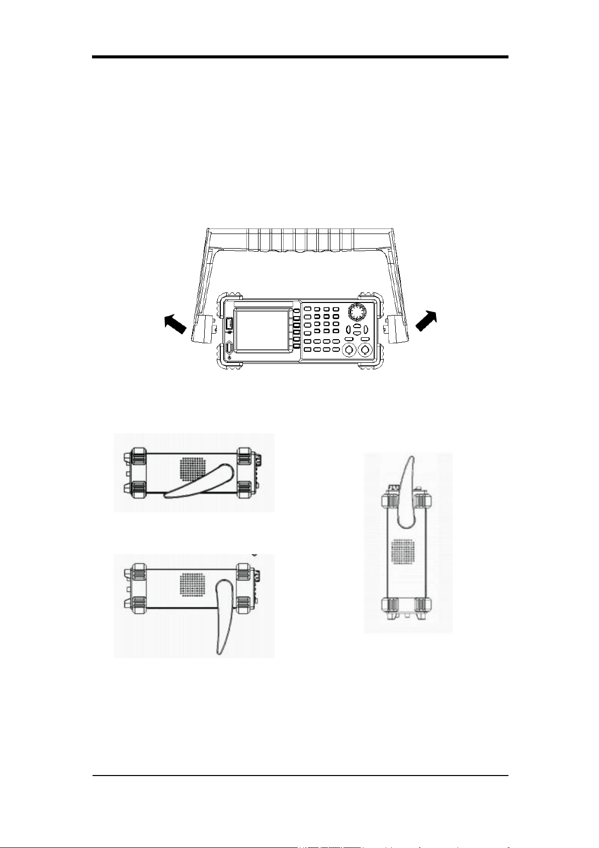
SIGLENT
SDG800 Quick Start 1
Adjustment Handle
When using the instrument, SDG800 permits users to adjust the handle to a
needed position which make it easier to operate and observe.
Adjustment Handle
Horizontal Position
Carrying Position
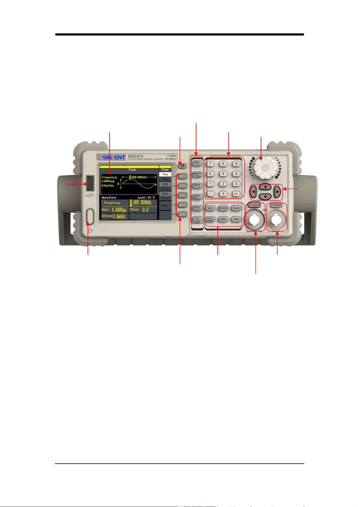
SIGLENT
2 SDG800 Quick Start
The Front Panel
The picture below shows SDG800 front panel composition:
1. Power Key
This key is used to turn on/off the SDG800. When the power key is off, the
SDG800 is under power off state.
2. USB Host
SDG800 supports USB disk of FAT format. It’s used to read waveforms or
status files from a U disk or save current instrument status to a U disk.
3. LCD Display
SDG800 has a 320*240 TFT color LCD display, which can display current
function menu, parameter settings, system state, promptings and so forth.
4. Back Key
This key is used to return to the last opertion menu.
3. LCD Display
4. Back Key
6. Number Keys 数7. Knob
1. Power Key
12. Menu Keys
2. USB
Host
8. Arrow
Keys
9. Channel
Control/Output Port
10. Trigger
Control/Output Port
11. Mode/Utility
Function KeyS
5. Waveform Option Area

SIGLENT
SDG800 Quick Start 3
5. Waveform Option Area
Sine ----Sine Waveform
Provide sine waveform output and its frequency ranges from 1μHz to
10MHz.
The backlight of the key lights when the key is being chosen.
The “Frequency/Period”, “Amplitude/High level”, “Offset/Low level”,
“Phase” of the sine waveform can be adjusted.
Square ----Square Waveform
Provide square waveform output and its frequency ranges from 1μHz to
10MHz.
The backlight of the key lights when the key is being chosen.
The “Frequency/Period”, “Amplitude/High level”, “Offset/Low level”,
“Phase” and “Duty” of the square waveform can be adjusted.
Ramp ----Ramp Waveform
Provide frequency ranges from 1μHz to 300KHz ramp waveform output.
The backlight of the key lights when the key is being chosen.
The “Frequency/Period”, “Amplitude/High level”, “Offset/Low level”,
“Phase” and “Symmetry” of the ramp waveform can be adjusted.
Pulse ----Pulse Waveform
Provide frequency ranges from 500μHz to 5MHz pulse waveform output.
The backlight of the key lights when the key is being chosen.
The “Frequency/Period”, “Amplitude/High level”, “Offset/Low level”,
“Pulse width/Duty” and “Rise/Fall” of the pulse waveform can be
adjusted.
Noise ----Noise Signal
Provide 10MHz bandwidth Gauss white noise output
The backlight of the key lights when the key is being chosen.
The “Variance” and “”Mean” of the noise signal can be adjusted.
Arb ----Arbitrary Waveform
Provide frequency ranges from 1μHz to 5MHz arbitrary waveform output.
It can output 46 kinds of waveforms: Sinc, index rose, exponential
decline, tangent, cotangent, inverse trigonometric, Guass and so on.
Besides, it can output the arbitrary waveforms in the U disk.
Users can on line edit (16Kpts) or edit through EsayWave arbitrary
waveform and down load them to the instrument.

SIGLENT
4 SDG800 Quick Start
The backlight of the key lights when the key is being chosen.
The “Frequency/Period”, “Amplitude/High level”, “Offset/Low level”,
“Phase” of the arbitrary waveform can be adjusted.
6. Number Keys
Those keys, including numbers from 0 to 9, radix points “.”, symbol keys
“+/-”, are used to input parameters. Pay attention: when you need to input
a negative, you should input a symbol “-” before you input the numbers.
7. Knob
It is used to increase (clockwise) or decrease (anticlockwise) current
outstanding numerical value when setting parameters.
8. Arrow Keys
When using knob to set parameters, it is used to switch the place of
numerical value.
When inputting a file name, it is used to move the position of cursor.
When saving or reading files, it is used to choose a position to save a file or
choose a file to be read.
9. Channel Control/Output Key
Output This key is used to turn on/off Channel output.
BNC connector and its nominal output impedance is 50Ω
When turn on Output (backlight is light), the connector output waveform
with current scheme.
10. Trigger Control/Output Key
Trigger This key is used to generate a manual trigger signal in the burst
mode.
This BNC connector is the Sweep/Burst trigger signal input port of external
trigger.
11. Mode/Utility Function Keys
Mod
This key is used to output modulated waveforms and provide several kinds
of mode modulate and digital modulate manners. It generates AM,
AM-DSB, FM, PM, ASK, FSK and PWM modulated signals.
It supports Internal modulate source.
The key backlight lights when the function key is being chosen.

SIGLENT
SDG800 Quick Start 5
Sweep
This key is used to generate “sine waveform”, “square waveform”,
“sawtooth waveform” and “arbitrary waveform” sweep signals.
It supports “Linear” and “Log” two kinds of sweep manners.
It supports “Internal” , “Manual” and “External” three kinds of trigger
source.
The backlight of the key lights when the key is being chosen.
Burst
This key is used to generate “sine waveform”, “square waveform”,
“sawtooth waveform” and “arbitrary waveform” burst output.
It supports “NCycle”, “Gated” and “Infinite” three kinds of burst modes.
Noises also can be used to generate gating burst.
It supports “Internal” , “Manual” and “External” three kinds of trigger
source.
The backlight of the key lights when the key is being chosen.
Store/Recall
Through this key users can save/recall instrument state or arbitrary
waveform datum edited by users.
As it supports file management system, users can do normal file
operations.
Besides a nonvolatile memory (C disk) inside, a U disk (D disk) can
also be outside connected.
The backlight of the key lights when the key is being chosen.
Utility
This key is used to set some system parameters and check version
information.
The backlight of the key lights when the key is being chosen.
Help
Press this key to obtain build-in help information about the product.
The backlight of the key lights when the key is being chosen.
12. Menu Keys
Those keys are corresponding one by one to the left menu, press any key to
activate corresponding menu.
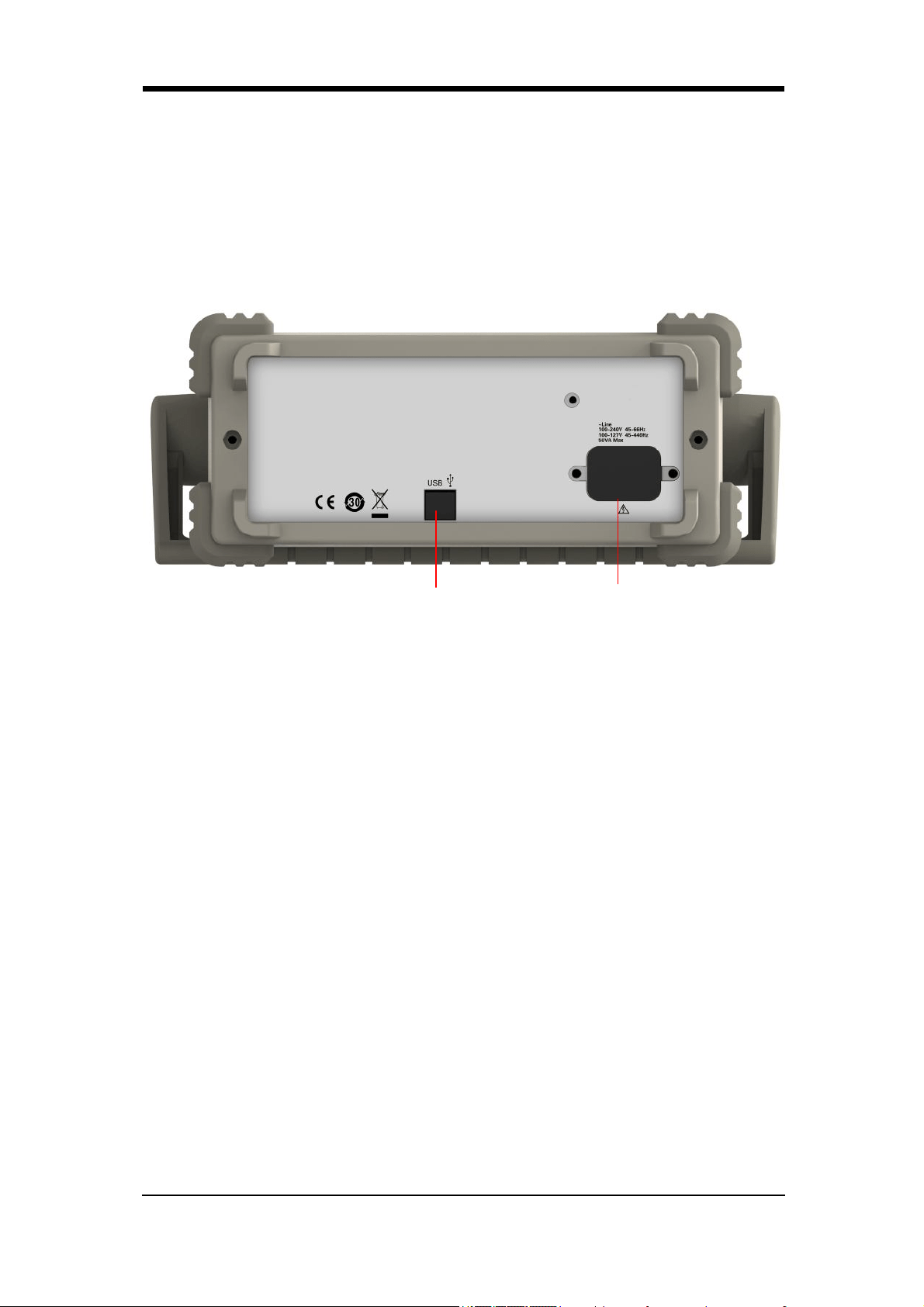
SIGLENT
6 SDG800 Quick Start
The Back Panel
1. AC Power Supply Input
SDG800 can input two different kinds of specification AC power supply.
AC power: 100—240V, 50/60 Hz or 100—127V, 50/60/440 Hz;
Fuse: 1.25AL, 250V
2. USB Device
Connect the instrument to a computer through the port, and use software
EasyWave to control the SDG800.
2 1
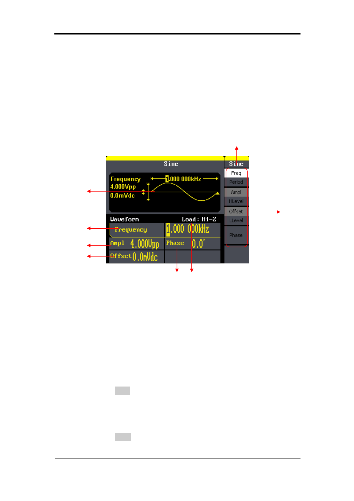
SIGLENT
SDG800 Quick Start 7
User Interface
SDG800 can only display one channel’s parameters and waveform. The
picture below shows the interface when choosing sine waveform. The
interface will have some difference when current function is different.
1. Current Function
Display current function name. For example: “sine” shows that sine
waveform function is being chosen.
2. Waveform Display Area
It shows each channel’s current waveform.
3. Frequency
It shows each channel’s current waveform’s frequency. After press
corresponding Freq menu, use number keys or knob to change the
parameter value.
4. Amplitude
It shows each channel’s current waveform’s amplitude. After press
corresponding Ampl menu, use number keys or knob to change the
parameter value.
6 7
8
1
2
3
4
5

SIGLENT
8 SDG800 Quick Start
5. Offset
It shows each channel’s current waveform’s DC offset. After press
corresponding Offset menu, use number keys or knob to change the
parameter value.
6. Phase
It shows each channel’s current waveform’s phase value. After press
corresponding Phase menu, use number keys or knob to change the
parameter value.
7. Load
It shows each channel’s load scheme.
High Resistance: display “Hi-Z” Load: display default “50Ω”
8. Menu
It shows the corresponding operation menu of the current function which is
being chosen. For example: the picture above shows the function menu of
“Sine” waveform.

SIGLENT
SDG800 Quick Start 9
Using Built-In Help System
To obtain build-in help information of the product, please press Help key
first, then use arrow keys to choose the help item you want, last press Select
to obtain help information.
Press Help key to open the common help information below:
1. View the instrument information.
2. Basic waveform output.
3. Arbitrary waveform output.
4. Generate a modulated waveform.
5. Sweep output.
6. Burst output.
7. Storage management.
8. Generate a DC-only signal.
9. Synchronize multiple instruments.
10. Reset the instrument to its default state.
11. Technical support.

SIGLENT
10 SDG800 Quick Start
Contact SIGLENT
SIGLENT TECHNOLOGIES CO., LTD
Address: 3/F, building NO.4, Antongda Industrial Zone, 3rd Liuxian
Road, Bao’an District, Shenzhen, China
Tel: +86- 755 -36615186
E-mail: sales@siglent.com
http: //www.siglent.com
QS02008-E02A

Programming Guide
1
Programming Guide
SDG Series
Function/Arbitrary
Waveform Generator
2016 SIGLENT TECHNOLOGIES CO., LTD

Programming Guide
2
Catalogue
1 PROGRAMMING OVERVIEW ...................................................................................................... 4
1.1 BUILD COMMUNICATION ........................................................................................................... 4
1.1.1 Install NI-VISA ................................................................................................................... 4
1.1.2 Connect the instrument ..................................................................................................... 6
1.2 HOW TO REMOTE CONTROL ...................................................................................................... 7
1.2.1 User-defined Programming ............................................................................................... 7
1.2.2 Send SCPI Commands via NI-VISA ...................................................................................... 7
2 INTRODUCTION TO THE SCPI LANGUAGE ................................................................................... 8
2.1 ABOUT COMMANDS & QUERIES ................................................................................................. 8
2.2 HOW THEY ARE LISTED ............................................................................................................. 8
2.3 HOW THEY ARE DESCRIBED ........................................................................................................ 8
2.4 WHEN CAN THEY BE USED ......................................................................................................... 8
2.5 COMMAND NOTATION .............................................................................................................. 8
2.6 TABLE OF COMMAND & QUERIES ................................................................................................ 9
3 COMMANDS AND QUERIES ...................................................................................................... 11
3.1 IEEE 488.2 COMMON COMMAND INTRODUCTION ....................................................................... 11
3.1.1 IDN ................................................................................................................................. 11
3.1.2 OPC ................................................................................................................................ 12
3.1.3 CLS ................................................................................................................................. 12
3.1.4 ESE ................................................................................................................................. 13
3.1.5 ESR ................................................................................................................................. 13
3.1.6 RST ................................................................................................................................. 14
3.1.7 SRE ................................................................................................................................. 14
3.1.8 STB ................................................................................................................................. 15
3.1.9 TST ................................................................................................................................. 15
3.1.10 WAI ................................................................................................................................ 16
3.1.11 DDR ................................................................................................................................ 16
3.1.12 CMR ............................................................................................................................... 17
3.2 COMM_HEADER COMMAND .................................................................................................... 18
3.3 OUTPUT COMMAND .............................................................................................................. 18
3.4 BASIC WAVE COMMAND ......................................................................................................... 20
3.5 MODULATE WAVE COMMAND .................................................................................................. 22
3.6 SWEEP WAVE COMMAND........................................................................................................ 26
3.7 BURST WAVE COMMAND ........................................................................................................ 28
3.8 PARAMETER COPY COMMAND .................................................................................................. 31
3.9 ARBITRARY WAVE COMMAND .................................................................................................. 31
3.10 SYNC COMMAND .................................................................................................................. 33
3.11 NUMBER FORMAT COMMEND .................................................................................................. 33
3.12 LANGUAGE COMMAND ........................................................................................................... 34

Programming Guide
3
3.13 CONFIGURATION COMMAND .................................................................................................... 35
3.14 BUZZER COMMAND ............................................................................................................... 35
3.15 SCREEN SAVE COMMAND ........................................................................................................ 35
3.16 CLOCK SOURCE COMMAND ...................................................................................................... 36
3.17 FREQUENCY COUNTER COMMAND ............................................................................................. 36
3.18 INVERT COMMAND ................................................................................................................ 37
3.19 COUPLING COMMAND ............................................................................................................ 38
3.20 VOLTAGE OVERLOAD COMMAND ............................................................................................... 39
3.21 STORE LIST COMMAND ........................................................................................................... 40
3.22 ARBITRARY WAVE DATA COMMAND ........................................................................................... 41
3.23 VIRTUAL KEY COMMAND ......................................................................................................... 43
3.24 IP COMMAND ...................................................................................................................... 44
3.25 SUBNET MASK COMMAND ...................................................................................................... 45
3.26 GATEWAY COMMAND ............................................................................................................. 46
3.27 SAMPLING RATE COMMAND .................................................................................................... 46
3.28 HARMONIC COMMAND........................................................................................................... 47
3.29 WAVEFORM COMBINING COMMAND ......................................................................................... 48
4 PROGRAMMING EXAMPLES ..................................................................................................... 49
4.1 EXAMPLE OF VC++ ................................................................................................................ 49
4.2 EXAMPLE OF VB.................................................................................................................... 55
4.3 EXAMPLE OF MATLAB ........................................................................................................... 62
4.4 EXAMPLE OF LABVIEW........................................................................................................... 64
5 INDEX ....................................................................................................................................... 67
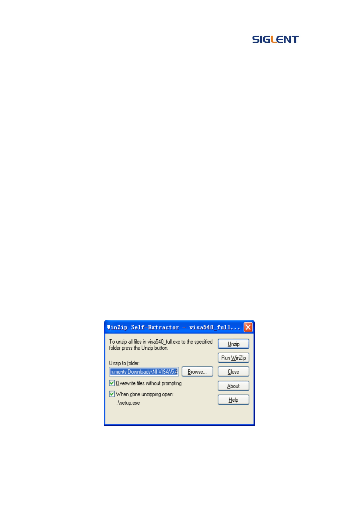
Programming Guide
4
1 Programming Overview
This chapter introduces how to build communication between SDG series
function/arbitrary waveform generator and the PC. It also introduces how to remote
control.
1.1 Build communication
1.1.1 Install NI-VISA
Before programming, you need to install NI-VISA, which you can download from
the NI-VISA web site. About NI-VISA, there are full version and Run-Time Engine
version. The full version include NI device driver and a tool named NI MAX that is a
user interface to control the device. The Run-Time Engine version which is much
smaller than the full version only include NI device driver.
For example, you can get NI-VISA 5.4 full version from:
http://www.ni.com/download/ni-visa-5.4/4230/en/.
You can also download NI-VISA Run-Time Engine 5.4 to your PC and install it as
default selection. This installation process is similar with the full version.
After you downloaded the file you can follow the steps below to install it:
i. Double click the visa540_full.exe, dialog shown as below:
ii. Click Unzip, the installation process will automatically launch after
unzipping files. If your computer needs to install .NET Framework 4,
its Setup process will auto start.
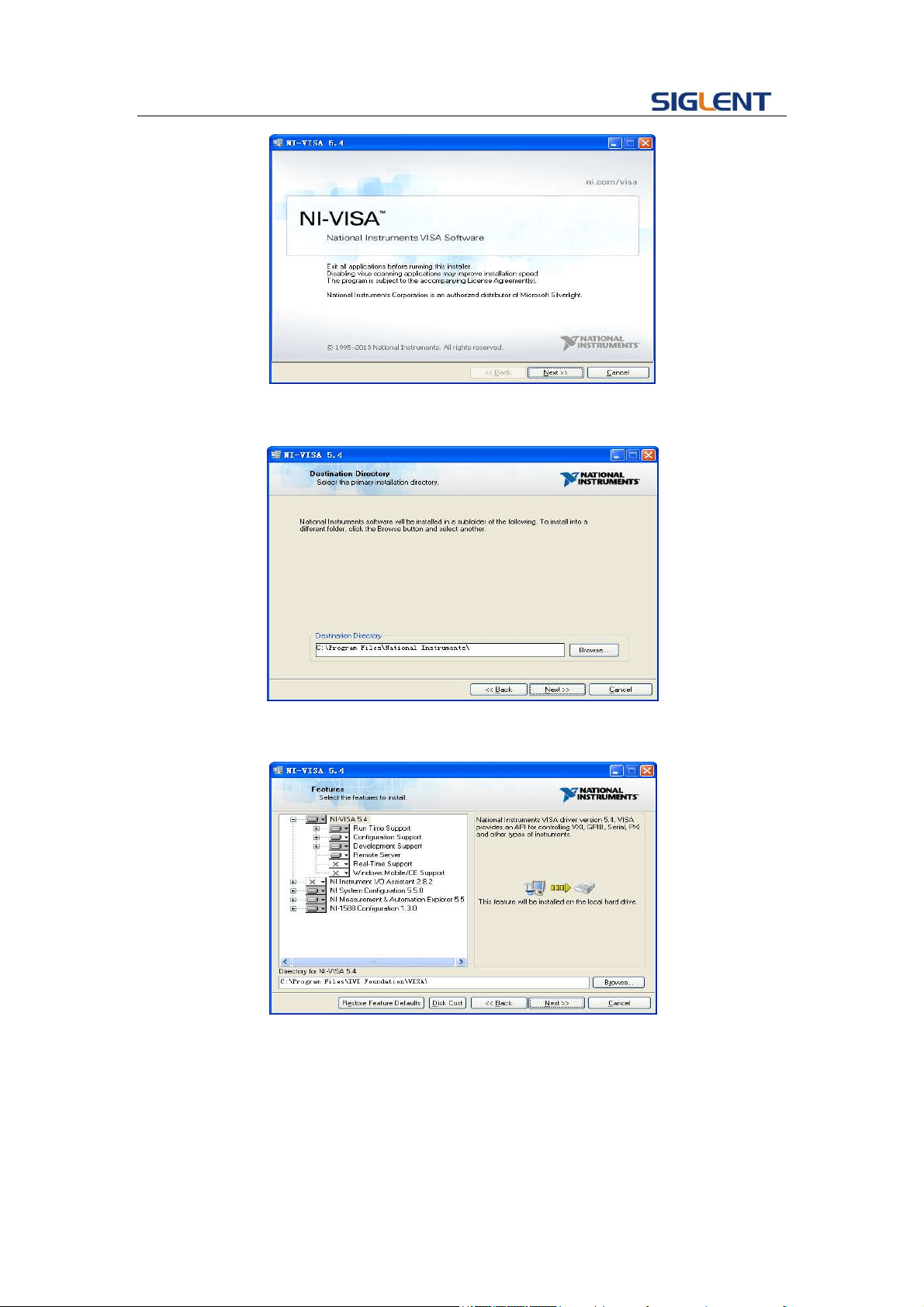
Programming Guide
5
iii. The NI-VISA installing dialog is shown above. Click Next to start the
installation process.
Set the install path, default path is “C:\Program Files\National
Instruments\”, you can change it. Click Next, dialog shown as above.
iv. Click Next twice, in the License Agreement dialog, select the “I accept
the above 2 License Agreement(s).”,and click Next, dialog shown as
below:
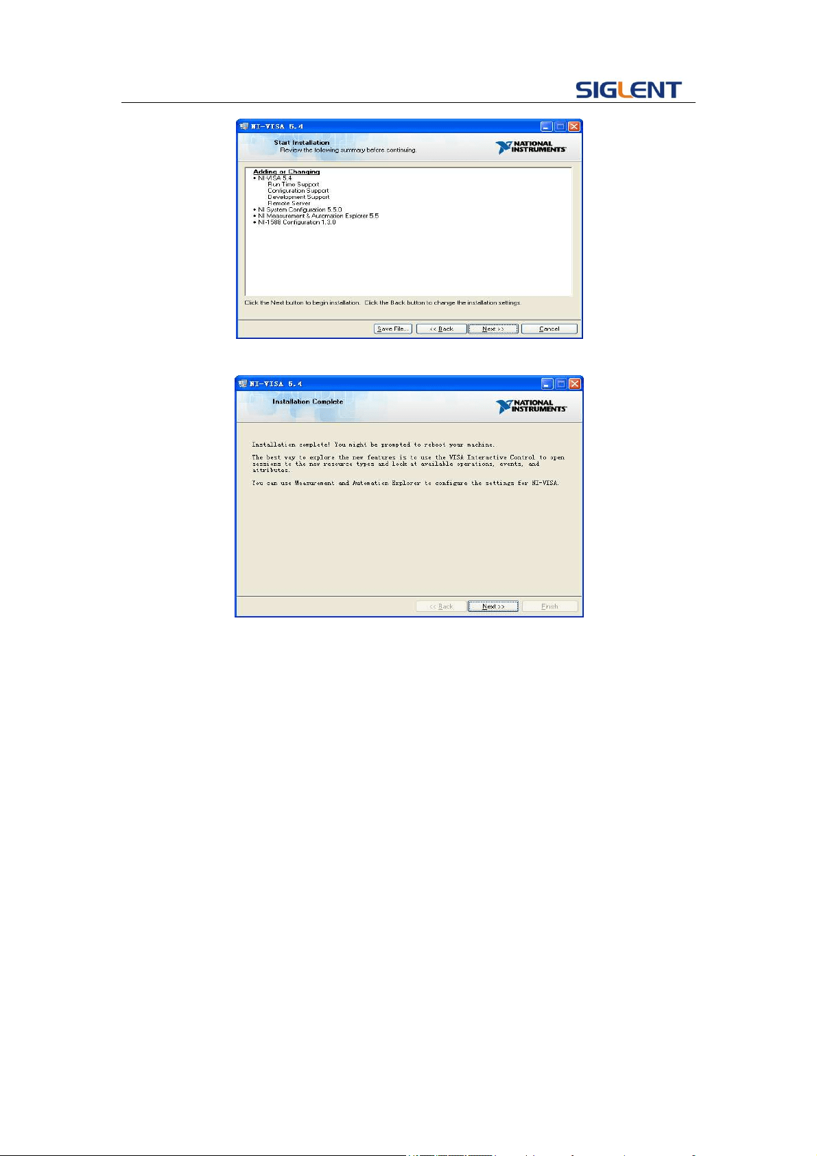
Programming Guide
6
v. Click Next to run installation.
Now the installation is complete, reboot your PC.
1.1.2 Connect the instrument
Depending on your specific model your function/arbitrary waveform generator may be
able to communicate with a PC through the USB or LAN interface. This manual takes the
USB as an example. But some examples may involve LAN.
a. Connect the function/arbitrary waveform generator and the USB Host interface of
the PC using a USB cable. Assuming your PC is already turned on, turn on your SDG
and your PC will display the “Device Setup” screen as it automatically installs the
device driver as shown below.

Programming Guide
7
b. Wait for the installation to complete and then proceed to the next step.
1.2 How To Remote Control
1.2.1 User-defined Programming
Users can use SCPI commands to program and control the function/arbitrary
waveform generator. For details, refer to the introductions in "Programming
Examples".
1.2.2 Send SCPI Commands via NI-VISA
You can control the SDG remotely by sending SCPI commands via NI-VISA software.

Programming Guide
8
2 Introduction to the SCPI Language
2.1 About Commands & Queries
This section lists and describes the remote control commands and queries recognized by
the instrument. All commands and queries can be executed in either local or remote state.
Each command or query, with syntax and other information, has some examples listed.
The commands are given in both long and short format at “COMMAND SYNTAX”and
“QUERY SYNTAX”, and the subject is indicated as a command or query or both. Queries
perform actions such as obtaining information, and are recognized by the question mark
(?) following the header.
2.2 How They are Listed
The descriptions are listed in alphabetical order according to their short format.
2.3 How They are Described
In the descriptions themselves, a brief explanation of the function performed is given. This
is followed by a presentation of the formal syntax, with the header given in
Upper-and-Lower-Case characters and the short form derived from it in ALL
UPPER-CASE characters. Where applicable, the syntax of the query is given with the
format of its response.
2.4 When can They be Used
The commands and queries listed here can be used for SDGxxxx Series
Function/Arbitrary Waveform Generators.
2.5 Command Notation
The following notations are used in the commands:
< > Angular brackets enclose words that are used placeholders ,of which there are two
types: the header path and the data parameter of a command.
:= A colon followed by an equals sign separates a placeholder, from the description of
the type and range of values that may be used in a command instead of the
placeholder.{ } Braces enclose a list of choices, one of which must be made.

Programming Guide
9
[ ] Square brackets enclose optional items.
… An ellipsis indicates that the items both to its left and right may be repeated for a
number of times.
2.6 Table of Command & Queries
Short
Long Form
Subsystem
What Command/Query does
*IDN
*IDN
SYSTEM
Gets identification from device.
*OPC
*OPC
SYSTEM
Gets or sets the OPC bit (0) in the Event
Status Register (ESR).
*CLS
*CLS
SYSTEM
Clears all the status data registers.
*ESE
*ESE
SYSTEM
Sets or gets the Standard Event Status
Enable register (ESE).
*ESR
*ESR
SYSTEM
Reads and clears the contents of the Event
Status Register (ESR).
*RST
*RST
SYSTEM
Initiates a device reset.
*SRE
*SRE
SYSTEM
Sets the Service Request Enable register
(SRE).
*STB
*STB
SYSTEM
Gets the contents of the IEEE 488.2
defined status register.
*TST
*TST
SYSTEM
Performs an internal self-test.
*WAI
*WAI
SYSTEM
Wait to continue command.
DDR
DDR
SYSTEM
Reads and clears the Device Dependent
Register (DDR).
CMR
CMR
SYSTEM
Reads and clears the command error
register.
CHDR
COMM_HEADER
SIGNAL
Sets or gets the command returned format
OUTP
OUTPUT
SIGNAL
Sets or gets output state.
BSWV
BASIC_WAVE
SIGNAL
Sets or gets basic wave parameters.
MDWV
MODULATEWAVE
SIGNAL
Sets or gets modulation parameters.
SWWV
SWEEPWAVE
SIGNAL
Sets or gets sweep parameters.
BTWV
BURSTWAVE
SIGNAL
Sets or gets burst parameters.
PACP
PARACOPY
SIGNAL
Copies parameters from one channel to the
other.
ARWV
ARBWAVE
DATA
Changes arbitrary wave type.
SYNC
SYNC
SIGNAL
Sets or gets synchronization signal.
NBFM
NUMBER_FORMAT
SYSTEM
Sets or gets data format.
LAGG
LANGUAGE
SYSTEM
Sets or gets language.
SCFG
SYS_CFG
SYSTEM
Sets or gets the power-on system setting
way.
BUZZ
BUZZER
SYSTEM
Sets or gets buzzer state.
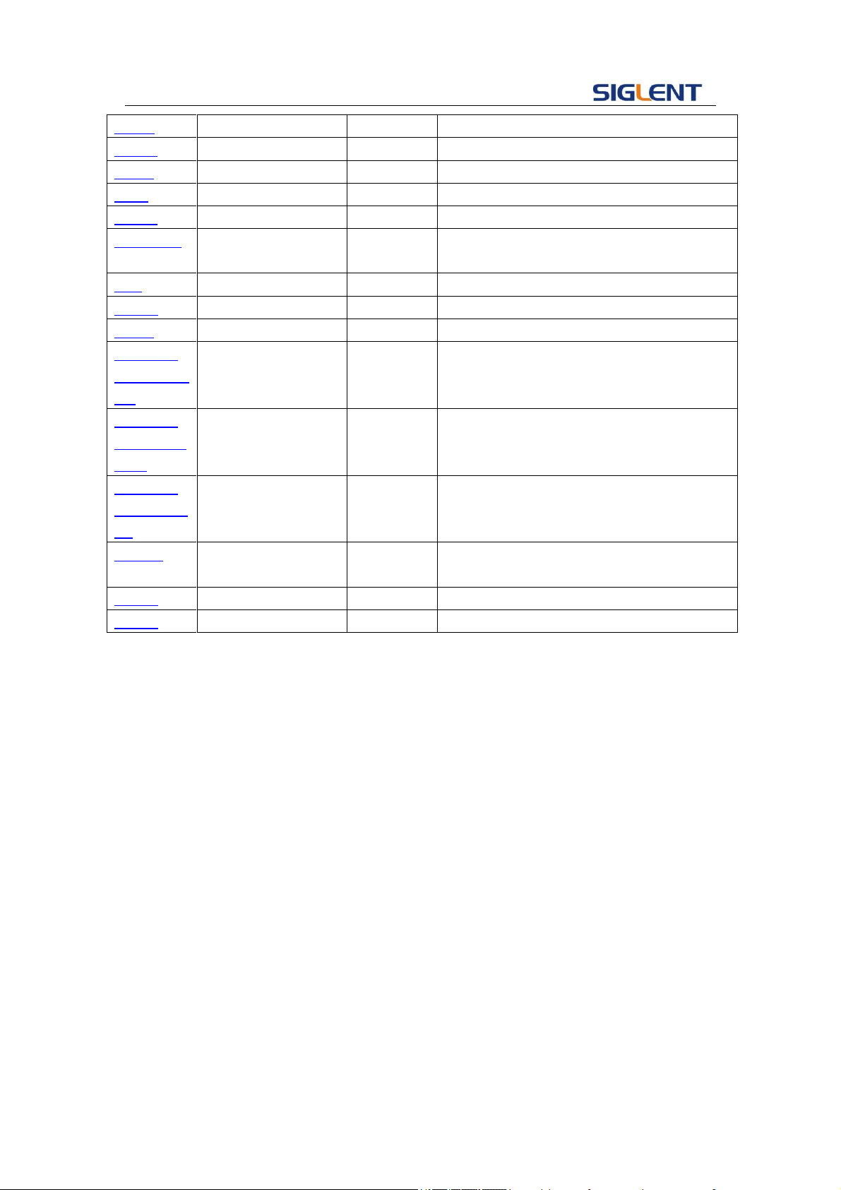
Programming Guide
10
SCSV
SCREEN_SAVE
SYSTEM
Sets or gets screen save state.
ROSC
ROSCILLATOR
SIGNAL
Sets or gets state of clock source.
FCNT
FREQCOUNTER
SIGNAL
Sets or gets frequency counter parameters.
INVT
INVERT
SIGNAL
Sets or gets polarity of current channel.
COUP
COUPLING
SIGNAL
Sets or gets coupling parameters.
VOLTPRT
VOLTPRT
SYSTEM
Sets or gets state of over-voltage
protection.
STL
STORELIST
SIGNAL
Lists all stored waveforms.
WVDT
WVDT
SIGNAL
Sets and gets arbitrary wave data.
VKEY
VIRTUALKEY
SYSTEM
Sets the virtual keys.
SYST:CO
MM:LAN:IP
AD
SYSTEM:COMMUN
ICATE:LAN:IPADDR
ESS
SYSTEM
The Command can set and get system IP
address.
SYST:CO
MM:LAN:S
MAS
SYSTEM:COMMUN
ICATE:LAN:SMASK
SYSTEM
The Command can set and get system
subnet mask.
SYST:CO
MM:LAN:G
AT
SYSTEM:COMMUN
ICATE:LAN:GATEW
AY
SYSTEM
The Command can set and get system
Gateway.
SRATE
SAMPLERATE
SIGNAL
Sets or gets sampling rate. You can only
use it in TrueArb mode
HARM
HARMonic
SIGNAL
Sets or gets harmonic information.
CMBN
CoMBiNe
SIGNAL
Sets or gets wave combine information.

Programming Guide
11
3 Commands and Queries
3.1 IEEE 488.2 Common Command Introduction
IEEE standard defines the common commands used for
querying the basic information of the instrument or executing
basic operations. These commands usually start with "*" and
the length of the keywords of the command is usually 3
characters.
3.1.1 IDN
DESCRIPTION
The *IDN? query causes the instrument to identify itself. The
response comprises manufacturer, model, serial number,
software version and firmware version.
QUERY SYNTAX
*IDN?
RESPONSE FORMAT
*IDN, <device id>,<model>,<serial number>,
<software version>, <hardware version>.
<device id>:=“SDG” is used to identify instrument.
<model>:= A model identifier less than 14 characters, should not
contain the word “MODEL”.
<serial number>:Each product has its own number, the serial
number can labeled product uniqueness.
<software version>:= A serial numbers about software version.
<hardware version>:=The hardware level field, should contain
information about all separately revisable subsystems. This
information can be contained in single or multiple revision codes.
EXAMPLE
Reads version information.
*IDN?
Return:
*IDN SDG, SDG5162, 120465, 5.01.02.05, 02-00-00-21
-24(It may differ from each version)

Programming Guide
12
Notes:
1)
Parameter/command
SDG800
SDG1000
SDG2000X
SDG5000
SDG1000X
<hardware version>
yes
yes
no
yes
no
2) Explain for <hardware version>:value1- value2- value3- value4- value5.
value1: PCB version.
value2: Hardware version.
value3: Hardware subversion.
value4: FPGA version.
value5: CPLD version.
3.1.2 OPC
DESCRIPTION
The *OPC (Operation Complete) command sets the OPC bit (bit
0) in the standard Event Status Register (ESR). This command
has no other effect on the operation of the device because the
instrument starts parsing a command or query only after it has
completely processed the previous command or query.
The *OPC? query always responds with the ASCII character 1
because the device only responds to the query when the
previous command has been entirely executed.
COMMAND SYNTAX
*OPC
QUERY SYNTAX
*OPC?
RESPONSE FORMAT
*OPC 1
3.1.3 CLS
DESCRIPTION
The *CLS command clears all the status data registers.
COMMAND SYNTAX
*CLS
EXAMPLE
The following command causes all the status data registers to be
cleared:
*CLS

Programming Guide
13
3.1.4 ESE
DESCRIPTION
The *ESE command sets the Standard Event Status Enable
register (ESE). This command allows one or more events in the
ESR register to be reflected in the ESB summary message bit
(bit 5) of the STB register.
The *ESE? query reads the contents of the ESE register.
COMMAND SYNTAX
*ESE <value>
<value> : = 0 to 255.
QUERY SYNTAX
*ESE?
RESPONSE FORMAT
*ESE <value>
EXAMPLE
The following instruction allows the ESB bit to be set if a user
request (URQ bit 6, i.e. decimal 64) and/or a device dependent
error (DDE bit 3, i.e. decimal 8) occurs. Summing these values
yields the ESE register mask 64+8=72.
*ESE?
Return:
*ESE 72
RELATED COMMANDS
*ESR
3.1.5 ESR
DESCRIPTION
The *ESR? query reads and clears the contents of the Event
Status Register (ESR). The response represents the sum of the
binary values of the register bits 0 to 7.
QUERY SYNTAX
*ESR?
RESPONSE FORMAT
*ESR <value>
<value> : = 0 to 255
EXAMPLE
The following instruction reads and clears the content of the ESR
register:
*ESR?
Return:
*ESR 0

Programming Guide
14
RELATED COMMANDS
*CLS, *ESE
3.1.6 RST
DESCRIPTION
The *RST command initiates a device reset. The *RST recalls
the default setup.
COMMAND SYNTAX
* RST
EXAMPLE
This example resets the signal generator:
*RST
3.1.7 SRE
DESCRIPTION
The *SRE command sets the Service Request Enable register
(SRE). This command allows the user to specify which summary
message bit(s) in the STB register will generate a service
request.
A summary message bit is enabled by writing a ‘1’ into the
corresponding bit location. Conversely, writing a ‘0’ into a given
bit location prevents the associated event from generating a
service request (SRQ). Clearing the SRE register disables SRQ
interrupts.
The *SRE? query returns a value that, when converted to a
binary number represents the bit settings of the SRE register.
Note that bit 6 (MSS) cannot be set and it’s returned value is
always zero.
COMMAND SYNTAX
*SRE <value>
<value> : = 0 to 255
QUERY SYNTAX
*SRE?
RESPONSE FORMAT
*SRE <value>
EXAMPLE
The following instruction allows a SRQ to be generated as soon
as the MAV summary bit (bit 4, i.e. decimal 16) or the INB
summary bit (bit 0, i.e. decimal 1) in the STB register, or both are
set. Summing these two values yields the SRE mask 16+1 = 17.
*SRE?
Return:

Programming Guide
15
*SRE 17
3.1.8 STB
DESCRIPTION
The *STB? query reads the contents of the 488.2 defined status
register (STB), and the Master Summary Status (MSS).
The response represents the values of bits 0 to 5 and 7 of the
Status Byte register and the MSS summary message.
The response to a *STB? query is identical to the response of a
serial poll except that the MSS summary message appears in bit
6 in place of the RQS message.
UERY SYNTAX
*STB?
RESPONSE FORMAT
*STB <value>
<value> : = 0 to 255
EXAMPLE
The following reads the status byte register:
*STB?
Return:
*STB 0
RELATED COMMANDS
*CLS, *SRE
3.1.9 TST
DESCRIPTION
The *TST? query performs an internal self-test and the response
indicates whether the self-test has detected any errors. The
self-test includes testing the hardware of all channels.
Hardware failures are identified by a unique binary code in the
returned <status> number. A “0” response indicates that no
failures occurred.
QUERY SYNTAX
*TST?
RESPONSE FORMAT
*TST <status>
<status> : = 0 self-test successful
EXAMPLE
The following causes a self-test to be performed:
TST?
Return(if no failure):
*TST 0

Programming Guide
16
RELATED COMMANDS
*CAL
Note:
Parameter/command
SDG800
SDG1000
SDG2000X
SDG5000
SDG1000X
TST
no
yes
yes
yes
yes
3.1.10 WAI
DESCRIPTION
The *WAI (WAIT to continue) command, requires by the IEEE
488.2 standard, has no effect on the instrument, as the
signal generator only starts processing a command when the
previous command has been entirely executed.
COMMAND SYNTAX
*WAI
RELATED COMMANDS
*OPC
3.1.11 DDR
DESCRIPTION
The DDR? query reads and clears the contents of the device
dependent or device specific error register (DDR). In case of a
hardware failure, the DDR register specifies the origin of the
failure.
QUERY SYNTAX
DDR?
RESPONSE FORMAT
DDR <value>
<value> : = 0 to 65535
EXAMPLE
DDR?
Return:
DDR 0
The following table gives details:
Bit
Bit Value
Description
15...14
Reserved
13
8192
Time-base hardware failure detected
12
4096
Trigger hardware failure detected
11
Reserved
10
Reserved
9
512
Channel 2 hardware failure detected
8
256
Channel 1 hardware failure detected

Programming Guide
17
7
128
External input overload condition detected
6…4
Reserved
3
Reserved
2
Reserved
1
2
Channel 2 overload condition detected
0
1
Channel 1 overload condition detected
Note:
Parameter/command
SDG800
SDG1000
SDG2000X
SDG5000
SDG1000x
DDR
yes
yes
no
yes
no
3.1.12 CMR
DESCRIPTION
The CMR? query reads and clears the contents of the command
error register (CMR) .See the table below which specifies the last
syntax error type detected by the instrument.
QUERY SYNTAX
CMR?
RESPONSE FORMAT
CMR <value>
<value> : = 0 to 14
EXAMPLE
CMR?
Return:
CMR 0
Value
Description
0
1
Unrecognized command/query header
2
Invalid character
3
Invalid separator
4
Missing parameter
5
Unrecognized keyword
6
String error
7
Parameter can’t allowed
8
Command String Too Long
9
Query cannot allowed
10
Missing Query mask
11
Invalid parameter
12
Parameter syntax error
13
Filename too long
14
Directory not exist

Programming Guide
18
Note:
Parameter/command
SDG800
SDG1000
SDG2000X
SDG5000
SDG1000X
CMR
yes
yes
no
yes
no
3.2 Comm_Header Command
DESCRIPTION
This command is used to change the query command returned
format. “SHORT” parameter returns short format. “LONG”
parameter returns long format. “OFF” returns nothing.
COMMAND SYNTAX
CHDR (Comm_HeaDeR) <parameter>
<parameter>:= {SHORT,LONG,OFF}
QUERY SYNTAX
CHDR (Comm_HeaDeR)?
RESPONSE FORMAT
CHDR <parameter>
EXAMPLE
Set query command format to long.
CHDR LONG
Read query command format.
CHDR?
Return:
COMM_HEADER LONG
Note:
Parameter/command
SDG800
SDG1000
SDG2000X
SDG5000
SDG1000X
CHDR
yes
yes
no
yes
no
3.3 Output Command
DESCRIPTION
Enable or disable the output of the [Output] connector at the front
panel corresponding to the channel.
The query returns “ON” or “OFF” and “LOAD”, “PLRT”
parameters.
COMMAND SYNTAX
<channel>:OUTP (OUTPut) <parameter>
<channel>:={C1, C2}
<parameter >:= {a parameter from the table below}
Parameters
Value
Description

Programming Guide
19
ON
---
Turn on
OFF
---
Turn off
LOAD
<load>
Value of load (
default unit is ohm
)
PLRT
<NOR, INVT>
Value of polarity
parameter
< load>:= {please see the note below.}
QUERY SYNTAX
<channel>: OUTP(OUTPut)?
RESPONSE FORMAT
<channel>: OUTP <load>
EXAMPLE
Turn on channel one.
C1: OUTP ON
Read channel one output state.
C1: OUTP?
Return:
C1: OUTP ON, LOAD, HZ, PLRT, NOR
Set the load to 50.
C1: OUTP LOAD, 50
Set the load to HZ.
C1: OUTP LOAD, HZ
Set the polarity normal.
C1: OUTP PLRT, NOR
Set the polarity inverted.
C1: OUTP PLRT, INVT
Note:
Parameter/command
SDG800
SDG1000
SDG2000X
SDG5000
SDG1000X
<channel>
no
yes
yes
yes
yes
LOAD
50, HZ
50~10000,
HZ
50~100000,
HZ
50, HZ
50~100000,
HZ

Programming Guide
20
3.4 Basic Wave Command
DESCRIPTION
Sets or gets basic wave parameters. In SDG1000X if turn on
wave combine, you can’t set wave to square. Combining a
square waveform is not possible.
COMMAND SYNTAX
<channel>:BSWV(BaSic_WaVe) <parameter>
<channel>:={C1, C2}
<parameter>:= {a parameter from the table below}
Parameters
Value
Description
WVTP
<type>
Type of wave
FRQ
<frequency>
Value of frequency. If wave type is Noise or DC, y
ou can’t set this parameter.
PERI
<period>
Value of period. If wave type is Noise or DC, you can’t
set this parameter.
AMP
<amplitude>
Value of amplitude. If wave type is Noise or DC, y
ou can’t set this parameter.
OFST
<offset>
Value of offset. If wave type is Noise or DC, you c
an’t set this parameter.
SYM
<symmetry>
Value of symmetry. Only when wave type is Ramp, you
can set this parameter.
DUTY
<duty>
Value of duty cycle. Only when wave type is Square and
Pulse, you can set this parameter.
PHSE
<phase>
Value of phase. If wave type is Noise or Pulse or
DC, you can’t set this parameter.
STDEV
<standard
deviation >
Value of Noise wave standard deviation. Only when
wave type is Noise, you can set this parameter.
MEAN
<mean>
Value of Noise wave mean. Only when wave type is
Noise, you can set this parameter.
WIDTH
<width>
Value of width. Only when wave type is Pulse, you can
set this parameter.
RISE
<rise>
Value of rise time. Only when wave type is Pulse, you
can set this parameter.
FALL
<fall>
Value of fall time. Only when wave type is Pulse, you
can set this parameter.
DLY
<delay>
Value of delay. Only when wave type is Pulse, you can
set this parameter.
HLEV
<high level>
Value of high level. If wave type is Noise or DC, you
can’t set this parameter.
LLEV
<low level>
Value of low level. If wave type is Noise or DC, you can’t
set this parameter.
BANDSTATE
<bandwidth
State of noise bandwidth switch. Only when wave type

Programming Guide
21
switch >
is Noise, you can set this parameter.
BANDWIDTH
<bandwidth
value>
Value of noise bandwidth. Only when wave type is
noise, you can set this parameter.
Note: if the command doesn’t set basic wave type, WVPT parameter will be set to current
wave type.
where: <type>:={SINE, SQUARE, RAMP, PULSE, NOISE, ARB ,DC}
<frequency>:= {Default unit is "Hz". Value depends on the model.}
<amplitude>:= {Default unit is "V". Value depends on the model.}
<offset>:= {Default unit is "V". Value depends on the model.}
<duty>:= {0% to 100%. Value depends on frequency.}
<symmetry> :={ 0% to 100%}
<phase>:= {0 to 360,In SDG2000X/SDG1000X,if you set 400,it will set
40(400-360)}
< standard deviation >:= {Default unit is "V". Value depends on the model.}
<mean>:= {Default unit is "V". Value depends on the model.}
<width>:= {Max_width < (Max_duty * 0.01) * period and Min_width >
(Min_duty * 0.01) * period.}
<rise>:= {Value depends on the model.}
<fall>:= {Value depends on the model.}
<delay>:= {Unit is S. Maximal is Pulse period, minimum value is 0.}
<bandwidth switch >:= {ON,OFF}
<bandwidth value>:= {value between 20MHz and 120MHz}
QUERY SYNTAX
<channel>: BSWV (BaSic_WaVe)?
<channel>:={C1, C2}
RESPONSE FORMAT
<channel>:BSWV<type>,<frequency>,<amplitude>,<offset>,
<duty>,<symmetry>, <phase>,<variance>,<mean>,<width>,
<rise>, <fall>, <delay>.
EXAMPLE
Change channel one wave type to ramp.
C1: BSWV WVTP, RAMP
Change frequency of channel one to 2000 Hz.
C1: BSWV FRQ, 2000
Set amplitude of channel one to 3Vpp.
C1: BSWV AMP, 3
Read channel basic wave parameters from device.
C1: BSWV?
Return:
C1: BSWV WVTP, SINE,FRQ,100HZ,PERI,0.01S,AMP,2V,
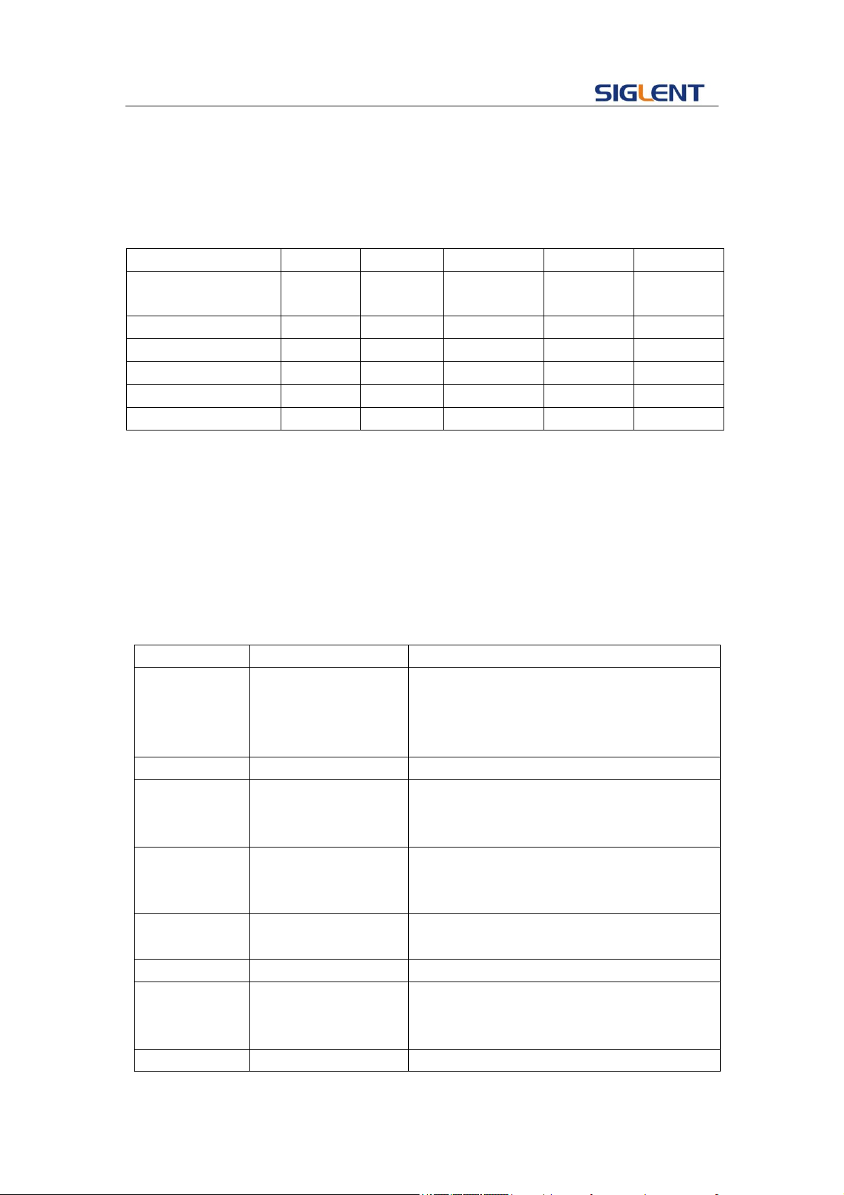
Programming Guide
22
OFST,0V,HLEV,1V,LLEV,-1V,PHSE,0
Set noise bandwidth value of channel one to 100MHz
C1: BSWV BANDWIDTH, 100000000
Note:
Parameter/command
SDG800
SDG1000
SDG2000X
SDG5000
SDG1000X
<channel>
no(single
channel)
yes
yes
yes
yes
RISE
yes
no
yes
yes
yes
FAL
yes
no
yes
yes
yes
DLY
no
yes
yes
yes
yes
BANDSTATE
no
no
yes
no
no
BANDWIDTH
no
no
yes
no
no
3.5 Modulate Wave Command
DESCRIPTION
Sets or gets modulation parameters.
COMMAND
SYNTAX
<channel>:MDWV(MoDulateWaVe)<parameter>
<channel>:={C1, C2}
<parameter>:= {a parameter from the table below}
Parameters
Value
Description
STATE
<state>
Turn on or off modulation. Note: if you want
to set or read other parameters of
modulation, you must set STATE to ON at
first.
AM, SRC
<src>
AM signal source.
AM, MDSP
<mod wave shape>
AM modulation wave. Only when AM sign
al source is set to INT, you can set the
parameter.
AM, FRQ
<AM frequency>
AM frequency. Only when AM signal sour
ce is set to INT, you can set the paramet
er.
AM, DEPTH
<depth>
AM depth. Only when AM signal source is set
to INT, you can set the parameter.
DSBAM, SRC
<src>
DSBAM signal source.
DSBAM,
MDSP
<mod wave shape>
DSBAM modulation wave. Only when AM
signal source is set to INT, you can set the
parameter.
DSBAM, FRQ
<DSB-AM
DSBAM frequency. Only when AM signal

Programming Guide
23
frequency>
source is set to INT, you can set the
parameter.
FM, SRC
<src>
FM signal source.
FM, MDSP
<mod wave shape>
FM modulation wave. Only when FM signal
source is set to INT, you can set the
parameter.
FM, FRQ
<FM frequency>
FM frequency. Only when FM signal source
is set to INT, you can set the parameter.
FM, DEVI
<FM frequency
deviation >
FM frequency deviation. Only when FM
signal source is set to INT. you can set the
parameter.
PM, SRC,
<src>
PM signal source.
PM, MDSP
<mod wave shape>
PM modulation wave. Only when PM signal
source is set to INT, you can set the
parameter.
PM, FRQ
<PM frequency>
PM frequency. Only when PM signal source
is set to INT, you can set the parameter.
PWM, FRQ
<PWM frequency>
PWM frequency. Only when carrier wave is
PULSE wave, you can set the parameter.
PWM, DEVI
<PWM dev>
Duty cycle deviation. Only when carrier wave
is PULSE wave, you can set the parameter.
PWM, MDSP
<mod wave shape>
PWM modulation wave. Only when carrier
wave is PULSE wave, you can set the
parameter.
PWM, SRC
<src>
PWM signal source.
PM, DEVI
<PM phase offset>
PM phase deviation. Only when PM signal
source is set to INT, you can set the
parameter.
ASK, SRC
<src>
ASK signal source.
ASK, KFRQ
<ASK key frequency>
ASK key frequency. Only when ASK signal
source is set to INT, you can set the
parameter.
FSK, KFRQ
<FSK key frequency>
FSK key frequency. Only when FSK signal
source is set to INT, you can set the
parameter.
FSK, HFRQ
<FSK hop
frequency>
FSK hop frequency.
FSK, SRC
<src>
FSK signal source.
PSK, KFRQ
<FSK key frequency>
PSK key frequency. Only when PSK signal
source is set to INT, you can set the
parameter.
PSK, SRC
<src>
PSK signal source.
CARR, WVTP
<wave type>
Carrier wave type.

Programming Guide
24
CARR, FRQ
<frequency>
Value of carrier frequency.
CARR, AMP
<amplitude>
Value of carrier amplitude.
CARR, OFST
<offset>
Value of carrier offset.
CARR, SYM
<symmetry>
Value of carrier symmetry. Only ramp can set
this parameter.
CARR, DUTY
<duty>
Value of duty cycle. Only square and pulse
can set this parameter.
CARR, PHSE
<phase>
Value of carrier phase.
CARR, RISE
<rise>
Value of rise time. Only Pulse can set this
parameter.
CARR, FALL
<fall>
Value of fall time. Only Pulse can set this
parameter.
CARR, DLY
<delay>
Value of carrier delay. Only PULSE can set
this parameter.
Note: If carrier wave is Noise you can’t set to turn on modulation.
If you want to set AM, FM, PM, CARR and STATE the first parameter have to be one of them.
where: <state>:={ON, OFF}
<src>:= {INT, EXT}
<mod wave shape>:={SINE, SQUARE, TRIANGLE, UP RAMP, DNRAMP,
NOISE, ARB}
<am frequency>:= {Default unit is "Hz". Value depends on the model.}
<depth>:= {0% to 120%}
<fm frequency>:= {Default unit is "Hz". Value depends on the model.}
<fm frequency deviation > :={ 0 to carrier frequency, Value depends on the
difference between carrier frequency and bandwidth frequency.}
<pm frequency> :={ Default unit is "Hz", Value depends on the model.}
<pm phase deviation >:= {0 to 360.}
<pwm frequency>:= {Default unit is "Hz", Value depends on the model. }
<pwm dev>:= { Default unit is "%",value depends on carrier duty cycle}
<ask key frequency>:= {Default unit is "Hz", Value depends on the model.}
<fsk frequency>:= { Default unit is "Hz", Value depends on the version.}
<fsk jump frequency>:= { the same with basic wave frequency}
<wave type>:={SINE ,SQUARE, RAMP, ARB, PULSE }
<frequency> :={ Default unit is "Hz", Value depends on the model.}
<amplitude> :={ Default unit is "V", Value depends on the model.}
<offset> :={ Default unit is "V", Value depends on the model.}
<duty>:= {0% to 100 %.}
<symmetry>:={ 0% to 100%}
<rise>:= {Value depends on the model.}
<fall>:= {Value depends on the model.}
<delay>:= {Default unit is "S".}

Programming Guide
25
Note:
There are some parameters Value depends on the model, You can read
version datasheet to get specific parameters
QUERY SYNTAX
<channel>: MDWV (MoDulateWaVe)?
<channel>:={C1, C2}
RESPONSE
FORMAT
<channel>:MDWV <parameter>
<parameter> :={ Return all parameter of the current modulation
parameters.}
EXAMPLE
Set channel one modulation type to AM.
C1: MDWV AM
Set modulation shape to AM, and set AM modulating wave type
to sine wave.
C1: MDWV AM, MDSP, SINE
Read channel one modulation parameters of which STATE is ON.
C1: MDWV?
Return:
C1:MDWV STATE,ON,AM,MDSP,SINE,SRC,INT,FRQ,100HZ,
DEPTH,100,CARR,WVTP,RAMP,FRQ,1000HZ,AMP,4V,OFST,0V,PHSE,
0, SYM, 50
Read channel one modulate wave parameters of which STATE is
OFF.
C1: MDWV?
Return:
C1: MDWV STATE, OFF
Set channel one FM frequency to 1000Hz
C1: MDWV FM, FRQ, 1000
Set channel one carrier shape to SINE.
C1: MDWV CARR, WVTP, SINE
Set channel one carrier frequency to 1000 Hz.
C1: MDWV CARR, FRQ,1000
RELATED
COMMANDS
ARWV, BTWV, SWWV, BSWV
Note:
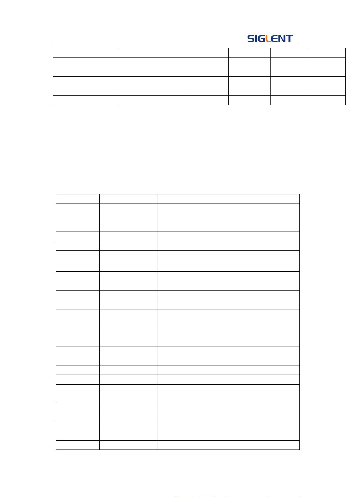
Programming Guide
26
Parameter/command
SDG800
SDG1000
SDG2000X
SDG5000
SDG1000x
<channel>
No(single channel)
yes
yes
yes
yes
[type], SRC
no(only internal source)
yes
yes
yes
yes
CARR, DLY
no
yes
yes
yes
yes
CARR, RISE
yes
no
yes
yes
yes
CARR, FALL
yes
n o
yes
yes
yes
[type]:={AM, FM, PM, FSK, ASK, DSBAM, PWM}
3.6 Sweep Wave Command
DESCRIPTION
Sets or gets sweep parameters.
COMMAND SYNTAX
<channel>SWWV(SweepWaVe) <parameter>
<channel>:={C1, C2}
<parameter>:= {a parameter from the table below}
Parameters
Value
Description
STATE
<state>
Turn on or off sweep. Note: if you want to set or
read other parameters you must set STATE to ON
at first.
TIME
<time>
Value of sweep time.
STOP
<stop frequency>
Value of stop frequency.
START
<start frequency>
Value of start frequency.
TRSR
<trigger src>
Trigger source.
TRMD
<trigger mode>
State of trigger output. If TRSR is EXT, the
parameter is invalid.
SWMD
<sweep mode>
Sweep style.
DIR
<direction>
Sweep direction.
EDGE
<edge>
Value of edge. Only when TRSR is EXT, the
parameter is valid.
MTRIG
<manual trigger>
Make a manual trigger. Only when TRSR is MAN,
the parameter is valid.
CARR,
WVTP
<wave type>
Carrier type.
CARR, FRQ
<frequency>
Value of carrier frequency.
CARR, AMP
<amplitude>
Value of carrier amplitude.
CARR,
OFST
<offset>
Value of carrier offset.
CARR, SYM
<symmetry>
Value of carrier symmetry, Only Ramp can set this
parameter.
CARR,
DUTY
<duty>
Value of carrier duty cycle. Only Square can set
this parameter.
CARR,
<phase>
Value of carrier phase.

Programming Guide
27
PHSE
Note: If carrier is Pulse or Noise you can’t turn on sweep.
If you want to set CARR and STATE, the first parameter has to be one of them.
where: <state>:= {ON, OFF}
<time>:= { Default unit is "S". Value depends on the model.}
<stop frequency> :={ the same with basic wave frequency}
<start frequency> :={ the same with basic wave frequency}
<trigger src>:= {EXT, INT, MAN}
<trigger mode>:= {ON, OFF}
<sweep mod>:= {LINE, LOG}
<direction>:= {UP, DOWN}
<edge>:={RISE, FALL}
<wave type>:={SINE ,SQUARE, RAMP, ARB}
<frequency> :={ Default unit is "Hz". Value depends on the
model.}
<amplitude> :={ Default unit is "V". Value depends on the model.}
<offset> :={ Default unit is "V", Value depends on the model.}
<duty>:= {0% to 100 %.}
<symmetry>:={ 0% to 100%}
Note:
There are some parameters Value depends on the model,
You can read version datasheet.
QUERY SYNTAX
<channel>: SWWV (SWeepWaVe)? <channel>:={C1, C2}
RESPONSE FORMAT
<parameter> :={ Return all parameters of the current sweep
wave.}
EXAMPLE
Set channel one sweep time to 1 S.
C1: SWWV TIME, 1
Set channel one sweep stop frequency to 1000 Hz.
C1: SWWV STOP, 1000
Read channel one sweep parameters of which STATE is
ON.
C2: SWWV?
Return:
C2: SWWV STATE, ON, TIME, 1S, STOP, 100HZ, START,
100HZ, TRSR, MAN,TRMD, OFF, SWMD, LINE, DIR, UP,
CARR, WVTP, SQUARE,
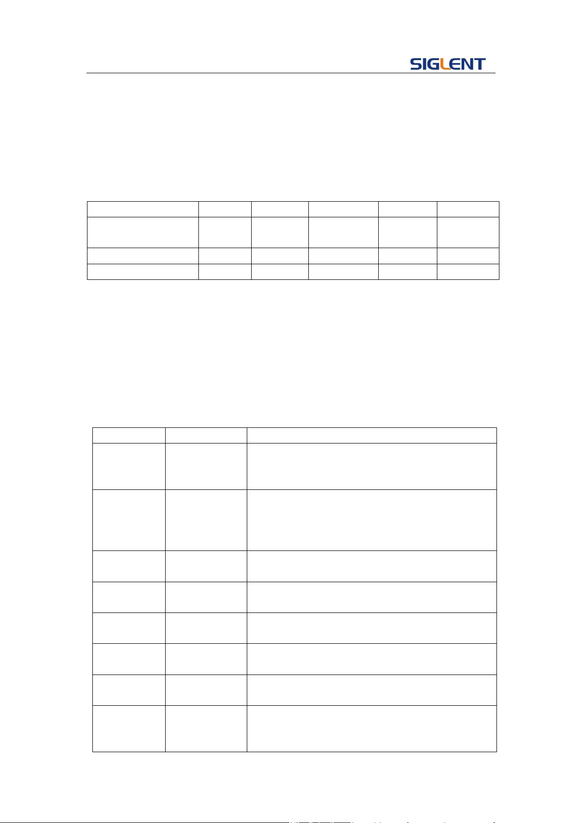
Programming Guide
28
FRQ, 1000HZ, AMP, 4V, OFST, 0V, DUTY, 50, PHSE, 0
Read channel two sweep parameters of which STATE is
OFF.
C2: SWWV?
Return:
C2: SWWV STATE, OFF
Note:
Parameter/command
SDG800
SDG1000
SDG2000X
SDG5000
SDG1000X
<channel>
no(single
channel)
yes
yes
yes
yes
TRMD
no
yes
yes
yes
yes
EDGE
no
yes
yes
yes
yes
3.7 Burst Wave Command
DESCRIPTION
Sets or gets burst wave parameters.
COMMAND SYNTAX
<channel>BTWV(BursTWaVe) <parameter>
<channel>:={C1, C2}
<parameter>:= {a parameter from the table below}
Parameters
Value
Description
STATE
<state>
Turn on or off burst. Note: If you want to set or read
other parameters of burst, you must set state to ON
at first.
PRD
<period>
Value of burst period. When carrier is NOISE wa
ve, you can’t set it. When GATE was chosen, yo
u can’t set it (but in SDG2000X, you can).And w
hen trigger source is EXT, you can’t set it.
STPS
<start phase>
Start phase of carrier. When carrier is NOISE or
PULSE wave, you can’t set it.
GATE_NCYC
<gate Ncycle>
Set the burst mode to GATE or NCYC. When ca
rrier is NOISE, you can’t set it.
TRSR
<trigger
source>
Set the trigger source.
DLAY
<delay>
Value of delay. When carrier is NOISE wave, you
can’t set it. When NCYC is chosen you can set it.
PLRT
<polarity>
Value of polarity. When GATE is chosen you can set
it. When carrier is NOISE, it is the only parameter.
TRMD
<trig mode>
Value of trigger mode. When carrier is NOISE wave,
you can’t set it. When NCYC is chosen you can set
it. When TRSR is set to EXT, you can’t set it.

Programming Guide
29
EDGE
<edge>
Value of edge. When carrier is NOISE wave, you
can’t set it. When NCYC is chosen and TRSR is set
to EXT, you can set it.
TIME
<circle time>
Value of Ncycle number. When carrier is NOISE
wave, you can’t set it. When NCYC is chosen you
can set it.
MTRIG
<manual trig>
Manual trigger. When TRSR is set to MAN, it can be
set.
CARR,
WVTP
<wave type>
Value of carrier type.
CARR, FRQ
<frequency>
Value of carrier frequency
CARR, AMP
<amplitude>
Value of carrier amplitude.
CARR, OFST
<offset>
Value of carrier offset.
CARR, SYM
<symmetry>
Value of symmetry. Only Ramp can set this
parameter.
CARR,
DUTY
<duty>
Value of duty cycle. Only Square or Pulse can set
this parameter.
CARR,
PHSE
<phase>
Value of carrier phase.
CARR, RISE
<rise>
Value of rise edge. Only when carrier is Pulse, the
Value is valid.
CARR, FALL
<fall>
Value of fall edge. Only when carrier is Pulse, the
Value is valid.
CARR,
STDEV
<standard
deviation >
Value of standard deviation. Only when carrier is
Noise, the Value is valid.
CARR,
MEAN
<mean>
Value of mean. Only when carrier wave is Noise, the
Value is valid.
CARR, DLY
<delay>
Value of delay. Only when carrier is Pulse, the
parameter is valid
Note: If you want to set CARR and STATE, the first parameter has to one of them
where: <state>:= {ON, OFF}
<period>:= {Default unit is “S”. Value depends on the model.}
<start phase>:= {0 to 360}
<gate ncycle>:= {GATE, NCYC}
<trigger source>:= {EXT, INT, MAN}
<delay>:= {Default unit is "S", Value depends on the model.}
<polarity>:= {NEG, POS}
<trig mode >:= {RISE, FALL, OFF}
<edge>:= { RISE, FALL}
<circle time> :={ Value depends on the Model (“INF” means
infinite).}

Programming Guide
30
<wave type>:={SINE ,SQUARE, RAMP, PULSE, NOISE, ARB}
<frequency> :={ Default unit is "HZ". Value depends on the model.}
<amplitude>:= {Default unit is "V". Value depends on the model.}
<offset>:= {Default unit is "V". Value depends on the model.}
<duty>:= {0% to 100%.}
<symmetry> :={ 0% to 100%}
<phase>:= {0 to 360}
< standard deviation >:= {Default unit is "V". Value depends on the
model.}
<mean>:= {Default unit is "V". Value depends on the model.}
<width> :={ Max_width < (Max_duty * 0.01) * period and
Min_width > (Min_duty * 0.01) * period.}
<rise>:= {Value depends on the model.}
<fall>:= {Value depends on the model.}
<delay>:= {Default unit is “S”.}
Note:
There are some parameters Value depends on the model,
You can read version datasheet to get specific parameters.
QUERY SYNTAX
<channel>: BTWV (BursTWaVe)? <parameter>
<channel>:={C1, C2}
<parameter>:=<period>……
RESPONSE FORMAT
<channel>:BTWV <type>,<state>,<period>……
EXAMPLE
Set channel one burst period to 1S.
C1: BTWV PRD, 1
Set channel one burst delay to 1s
C1: BTWV DLAY, 1
Set channel one burst to infinite
C1: BTWV TIME, INF
Read channel two burst parameters of which STATE is
ON.
C2: BTWV?
Return:
C2: BTWV STATE,ON,PRD,0.01S,STPS,0,TRSR,INT,
TRMD,OFF,TIME,1,DLAY,2.4e-07S,GATE_NCYC,NCYC,
CARR,WVTP,SINE,FRQ,1000HZ,AMP,4V,OFST,0V,PHSE,0
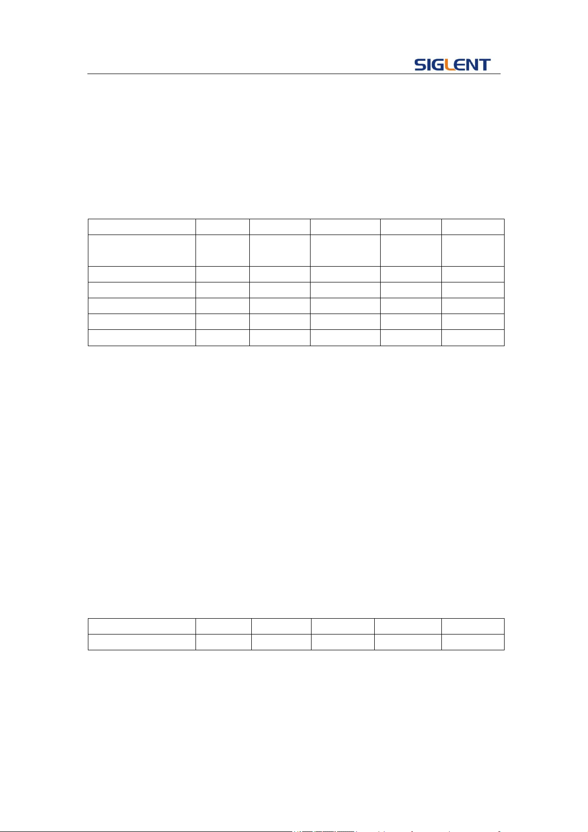
Programming Guide
31
Read channel two burst parameters of which STATE is
OFF.
C2: BTWV?
Return:
C2: BTWV STATE, OFF
Note:
Parameter/command
SDG800
SDG1000
SDG2000X
SDG5000
SDG1000X
<channel>
no(single
channel)
yes
yes
yes
yes
TRMD
no
yes
yes
yes
yes
EDGE
no
yes
yes
yes
yes
CARR, DLY
yes
yes
yes
yes
yes
CARR, RISE
yes
no
yes
yes
yes
CARR, FALL
yes
no
yes
yes
yes
3.8 Parameter Copy Command
DESCRIPTION
Copies parameters from one channel to another.
COMMAND SYNTAX
PACP(ParaCoPy) <destination channel>, <src channel>
< destination channel>:= {C1, C2}
<src channel>:= {C1, C2}
Note: the parameters C1 and C2 must be set to the device
together.
EXAMPLE
Copy parameters from channel one to channel two.
PACP C2, C1
RELATED COMMANDS
ARWV, BTWV, MDWV, SWWV, BSWV
Note:
Parameter/command
SDG800
SDG1000
SDG2000X
SDG5000
SDG1000X
PACP
no
yes
yes
yes
yes
3.9 Arbitrary Wave Command
DESCRIPTION
Sets and gets arbitrary wave type.
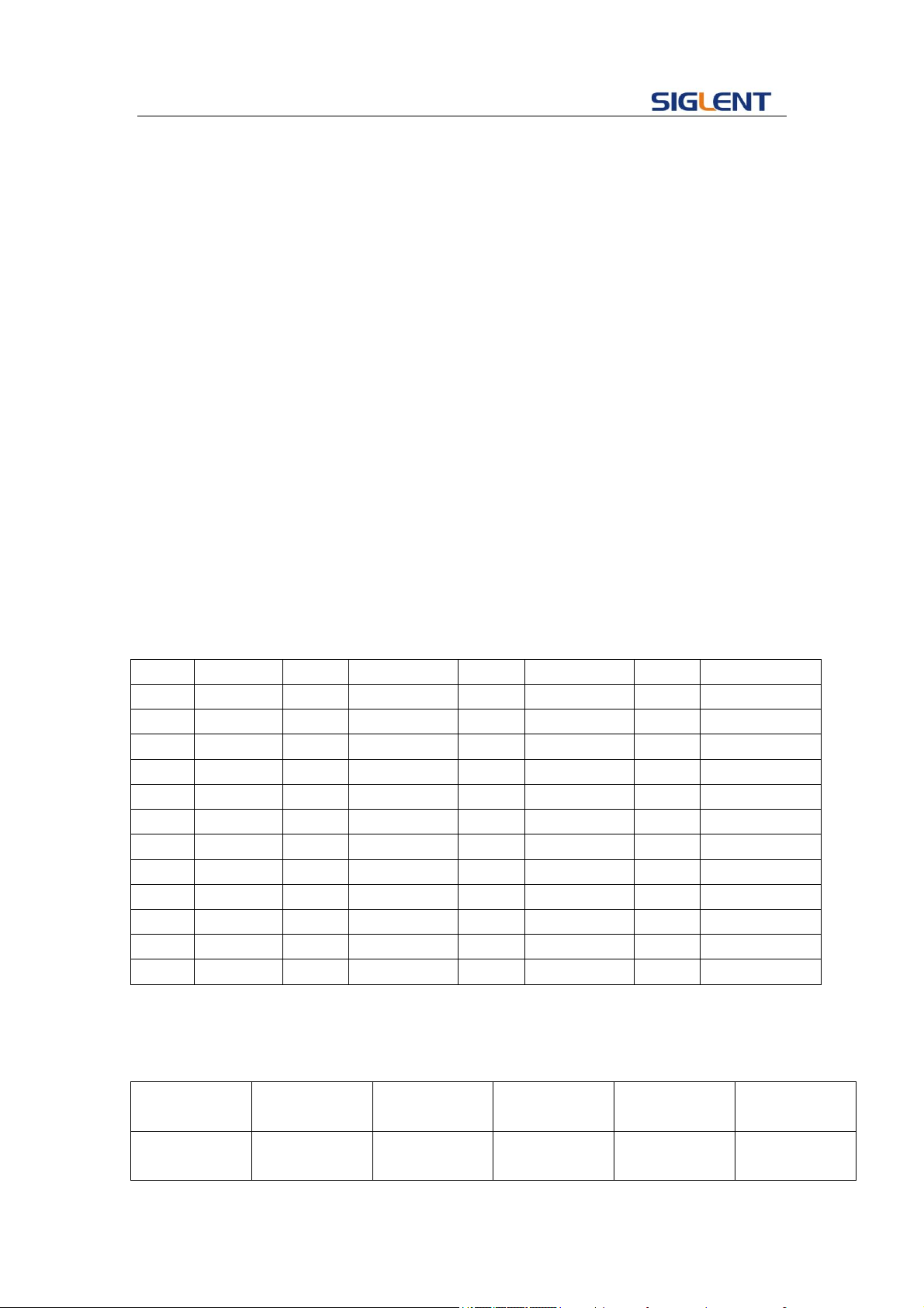
Programming Guide
32
COMMAND SYNTAX
<channel> ARWV(ArbWaVe) INDEX,<value1>, NAME,<value2>
<channel>:={C1, C2}
< value1>: the table below shows what the index number mean.)
< value2>: see table below.
QUERY SYNTAX
<channel>: ARWV (ARbWaVe)?
<channel>:={C1, C2}
RESPONSE FORMAT
<channel>:ARWV <index>
EXAMPLE
Set StairUp arbitrary wave output by index.
C1:ARWV INDEX, 2
Read system current wave.
ARWV?
Return:
ARWV INDEX,2,NAME,StairUp
Set Cardiac arbitrary wave output by name.
ARWV NAME, Cardiac
<table>:
Index
Name
Index
Name
Index
Name
Index
Name
0
Sine
12
Logfall
24
Gmonopuls
36
Triang
1
Noise
13
Logrise
25
Tripuls
37
Harris
2
StairUp
14
Sqrt
26
Cardiac
38
Bartlett
3
StairDn
15
Root3
27
Quake
39
Tan
4
Stairud
16
X^2
28
Chirp
40
Cot
5
Ppulse
17
X^3
29
Twotone
41
Sec
6
Npulse
18
Sinc
30
Snr
42
Csc
7
Trapezia
19
Gaussian
31
Hamming
43
Asin
8
Upramp
20
Dlorentz
32
Hanning
44
Acos
9
Dnramp
21
Haversine
33
Kaiser
45
Atan
10
Exp_fall
22
Lorentz
34
Blackman
46
Acot
11
Exp_rise
23
Gauspuls
35
Gausswin
47
Square
About the table: This table is just an example, the index may depend on the model, you
can execute “STL?” command to get them accurately.
Note:
Parameter/co
mmand
SDG800
SDG1000
SDG2000X
SDG5000
SDG1000X
<channel>
no(single
channel)
yes
yes
yes
yes

Programming Guide
33
INDEX
yes
yes
yes(only
built-in wave)
yes
yes(only
built-in wave)
NAME
yes
yes
yes(user
define wave)
yes
yes(user
define wave)
3.10 Sync Command
DESCRIPTION
Sets synchronization signal.
COMMAND SYNTAX
<channel>: SYNC <parameter>
<channel>:={C1, C2}
<parameter>:= {ON, OFF}
QUERY SYNTAX
<channel>: SYNC?
<channel>:={C1, C2}
RESPONSE FORMAT
<channel>:SYNC <parameter>
EXAMPLE
Turn on sync function of channel one.
C1: SYNC ON
Read state of channel one sync.
C1: SYNC?
Return:
C1: SYNC OFF
Note:
Parameter/command
SDG800
SDG1000
SDG2000X
SDG5000
SDG1000X
SYNC
no
yes
yes
yes
yes
3.11 Number Format Commend
DESCRIPTION
Sets or gets number format.
COMMAND SYNTAX
NBFM(NumBer_ForMat) <parameter>
<parameter> :={ a parameter from the table below.}
Parameters
Value
Description
PNT
<pnt>
Point format
SEPT
<sept>
Separator format
Where:
<pnt>:= {Dot, Comma}.
<sept> :={ Space, Off, On}.

Programming Guide
34
QUERY SYNTAX
NBFM (NumBer_ForMat)?
RESPONSE FORMAT
NBFM <parameter>
EXAMPLE
Set point format to DOT.
NBFM PNT, DOT
Set Separator format to ON.
NBFM SEPT,ON
Read number format.
NBFM?
Return:
NBFM PNT, DOT, SEPT, ON
3.12 Language Command
DESCRIPTION
Sets or gets system language.
COMMAND SYNTAX
LAGG(LAnGuaGe) <parameter>
<parameter>:={EN, CH, RU}
QUERY SYNTAX
LAGG (LAnGuaGe)?
RESPONSE FORMAT
LAGG <parameter>
EXAMPLE
Set language to English.
LAGG EN
Read language
LAGG?
Return:
LAGG EN
Note:
Parameter/command
SDG800
SDG1000
SDG2000X
SDG5000
SDG1000X
RU
no
yes
no
no
no

Programming Guide
35
3.13 Configuration Command
DESCRIPTION
Sets or gets the power-on system setting..
COMMAND SYNTAX
SCFG(Sys_CFG)<parameter>
<parameter>:= {DEFAULT, LAST}
QUERY SYNTAX
SCFG (Sys_CFG)?
RESPONSE FORMAT
SCFG <parameter>
EXAMPLE
Set the power-on system setting to LAST.
SCFG LAST
3.14 Buzzer Command
DESCRIPTION
Turns on or off the buzzer.
COMMAND SYNTAX
BUZZ(BUZZer) <parameter>
<parameter>:= {ON, OFF}
QUERY SYNTAX
BUZZ (BUZZer)?
RESPONSE FORMAT
BUZZ <parameter>
EXAMPLE
Turn on the buzzer.
BUZZ ON
3.15 Screen Save Command
DESCRIPTION
Turns off or sets screen save time (default unit is minutes).
COMMAND SYNTAX
SCSV (SCreen_SaVe) <parameter>
<parameter>:= {OFF, 1, 5, 15, 30, 60, 120, 300 }
QUERY SYNTAX
SCSV (SCreen_SaVe)?
RESPONSE FORMAT
SCreen_SaVe <parameter>

Programming Guide
36
EXAMPLE
Set screen save time to 5 minutes.
SCSV 5
Read the current screen save time.
SCreen_SaVe?
Return:
SCSV 5MIN
3.16 Clock Source Command
DESCRIPTION
Sets or gets the clock source.
COMMAND SYNTAX
ROSC (ROSCillator) <parameter>
<parameter>:= {INT, EXT}
QUERY SYNTAX
ROSC (ROSCillator)?
RESPONSE FORMAT
ROSC <parameter>
EXAMPLE
Set internal time base as the clock source.
ROSC INT
Note:
Parameter/command
SDG800
SDG1000
SDG2000X
SDG5000
SDG1000X
ROSC
no
yes
yes
yes
yes
3.17 Frequency Counter Command
DESCRIPTION
Sets or gets frequency counter parameters.
COMMAND SYNTAX
FCNT(FreqCouNTer) <parameter>
<parameter>:= {a parameter from the table below}
Parameters
Value
Description
STATE
<state>
State of frequency counter.
FRQ
<frequency>
Value of frequency. Can’t be set.
PW
<position width>
Value of positive width. Can’t be set.
NW
<negative width>
Value of negative width. Can’t be set.
DUTY
<duty>
Value of duty cycle. Can’t be set.
FRQDEV
<freq deviation>
Value of freq deviation. Can’t be set.
REFQ
<ref freq>
Value of reference freq.

Programming Guide
37
TRG
<triglev>
Value of trigger level.
MODE
<mode>
Value of mode.
HFR
<HFR>
State of HFR.
where: < state >:={ON, OFF}
<frequency>:= {Default unit is "Hz". Value range depends on the model.}
< mode >:={AC, DC}
<HFR>:={ON, OFF}
QUERY SYNTAX
FCNT (FreqCouNTer)?
RESPONSE FORMAT
FCNT < state ><frequency><duty><ref freq><triglev><position
width><negative width>
<freq deviation><mode><HFR>
EXAMPLE
Turn frequency counter on:
FCNT STATE,ON
Set reference freq to 1000Hz:
FCNT REFQ,1000
Query frequency counter information:
FCNT?
Return:
FCNT STATE,ON,FRQ,10000000HZ,DUTY,59.8568,REFQ,
1e+07HZ,TRG,0V,PW,5.98568e-08S,NW,4.01432e-08S,FR
QDEV,0ppm,MODE,AC,HFR,OFF
Note:
Parameter/command
SDG800
SDG1000
SDG2000X
SDG5000
SDG1000X
FCNT
no
yes
yes
yes
yes
3.18 Invert Command
DESCRIPTION
Sets or gets polarity of current channel.
COMMAND SYNTAX
<channel>:INVT(INVerT) <parameter>
<channel>:={C1, C2}
<parameter>:= {ON, OFF}
QUERY SYNTAX
<channel>: INVT (INVerT)?
<channel>:={C1, C2}
RESPONSE FORMAT
<channel>:INVerT <parameter>
EXAMPLE
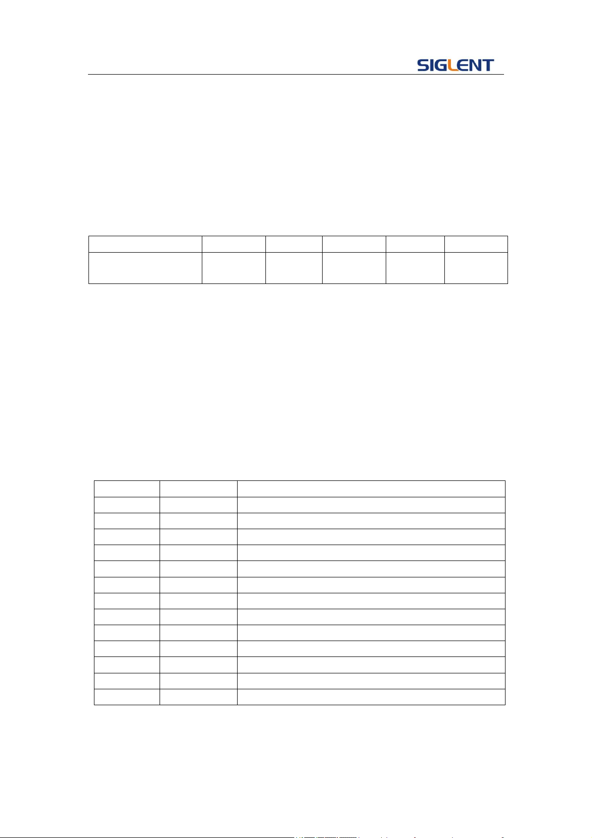
Programming Guide
38
Set C1 ON:
C1: INVT ON
Read the polarity of channel one.
C1: INVT?
Return:
C1: INVT ON
Notes:
1.
Parameter/command
SDG800
SDG1000
SDG2000X
SDG5000
SDG1000X
<channel>
no(single
channel)
yes
yes
yes
yes
2. The <channel> is a selectable parameter. If channel is not set, default is current
channel.
3.19 Coupling Command
DESCRIPTION
Sets or gets channel coupling parameters. You can only set coupling
value when trace switch off.
COMMAND
SYNTAX
COUP (COUPling)<parameter>
<parameter>:= {a parameter from the table below}
Parameters
Value
Description
TRACE
<trace>
Trace switch
STATE
<state>
State of channel coupling.
BSCH
<bsch>
Value of base channel.
FDEV
<frq_dev>
Value of f frequency deviation.
PDEV
<pha_dev>
Value of position phase deviation.
FCOUP
<fcoup>
Value of frequency coupling switch
FRAT
<frat>
Value of frequency coupling ratio
PCOUP
<pcoup>
Value of phase coupling switch
PRAT
<prat>
Value of phase coupling ratio
ACOUP
<acoup>
Value of amplitude coupling switch
ARAT
<arat>
Value of amplitude coupling ratio
ADEV
<adev>
Value of amplitude coupling deviation
where:
<trace>:={ON, OFF}
< state >:={ON, OFF}

Programming Guide
39
< bsch >:= {CH1, CH2}
< frq_dev >:={ Default unit is “Hz”, value range depends on the model}
< pha_dev >:={ Default unit is “°”value range depends on the model }
<fcoup>,<acoup>,<pcoup>:={ON, OFF}
<frat>,<prat>,< arat >:={a ratio value. value range depends on the model }
<adev>:={ a deviation value. value range depends on the model }
QUERY SYNTAX
EXAMPLE
COUP (COUPling)?
Set SDG5000 coupling state on
COUP STATE,ON
Set SDG5000 frequency deviation value 5Hz
COUP FDEV,5
Set SDG2000x amplitude coupling ratio
COUP ARAT,2
Query SDG2000X coupling information.
COUP?
Return:
COUP\sTRACE,OFF,FCOUP,ON,PCOUP,ON,ACOUP,ON,FDEV,5HZ,
PRAT,1,ARAT,2\n
Note:
Parameter/command
SDG800
SDG1000
SDG2000X
SDG5000
SDG1000X
TRACE
no
no
yes
no
yes
STATE
yes
yes
no
yes
no
BSCH
yes
yes
no
yes
no
FCOUP
no
no
yes
no
yes
FRAT
no
no
yes
no
yes
PCOUP
no
no
yes
no
yes
PRAT
no
no
yes
no
yes
ACOUP
no
no
yes
no
yes
ARAT
no
no
yes
no
yes
ADEV
no
no
yes
no
yes
3.20 Voltage Overload Command
DESCRIPTION
Sets or gets state of over-voltage protection.

Programming Guide
40
COMMAND SYNTAX
VOLTPRT<parameter>
<parameter>:= {ON, OFF}
QUERY SYNTAX
VOLTPRT?
RESPONSE FORMAT
VOLTPRT<parameter>
Note:
Parameter/command
SDG800
SDG1000
SDG2000X
SDG5000
SDG1000X
VOLTPRT
no
yes
yes
no
yes
3.21 Store List Command
DESCRIPTION
This command is used to read the stored wave data names if the
store unit is empty; the command will return “EMPTY” string.
Note: M50~ M59 is user defined memory. The name will return
what you defined. if you do not define an arbitrary name, it will
return “EMPTY”(It is depends on the model).
QUERY SYNTAX
STL (StoreList)? BUILDIN, USER
EXAMPLE
Read all arbitrary data saved in the device.
STL?
Return:
STL M0, StairUp, M1, StairDn, M2, StairUD, M3, Trapezia, M4,
ExpFall, M5, ExpRise, M6, LogFall, M7, LogRise, M8, Sqrt, M9,
X^2, M10, Sinc, M11, Gaussian, M12, Dlorentz, M13, Haversine,
M14, Lorentz, M15, Gauspuls, M16, Gmonopuls, M17, Cardiac,
M18, Quake, M19, TwoTone, M20, SNR, M21, Hamming, M22,
Hanning, M23, Kaiser, M24, Blackman, M25, GaussiWin, M26,
Harris, M27, Bartlett, M28, Tan, M29, Cot, M30, Sec, M31, Csc,
M32, Asin, M33, Acos, M34, Atan, M35, ACot, M36, EMPTY,
M37 .….
Read built-in wave data.
STL? BUILDIN
Return:
STL M0, Sine, M1, Noise, M10, ExpFal, M11, ExpRise, M12,
LogFall, M13, LogRise, M14, Sqrt, M15, Root3, M16, X^2,
M17, X^3, M18, Sinc, M19, Gussian, M2, StairUp, M20,
Dlorentz, M21, Haversine, M22, Lorentz, M23, Gauspuls,

Programming Guide
41
M24, Gmonopuls, M25, Tripuls, M26, Cardiac, M27, Quake,
M28, Chirp, M29, Twotone, M3, StairDn, M30, SNR, M31,
Hamming, M32, Hanning, M33, kaiser, M34, Blackman, M35,
Gausswin, M36, Triang, M37, Harris, M38, Bartlett, M39, Tan,
M4, StairUD, M40, Cot, M41, Sec, M42, Csc, M43, Asin, M44,
Acos, M45, Atan, M46, Acot, M47, Square, M5, Ppulse, M6,
Npulse, M7, Trapezia, M8, Upramp, M9, Dnramp
Read wave data defined by user.
STL? USER
Return:
STL
WVNM,sinec_8M,sinec_3000000,sinec_1664000,ramp_8M,
sinec_2000000,sinec_50000,square_8M,sinec_5000,wave1,
square_1M
Note:
Parameter/command
SDG800
SDG1000
SDG2000X
SDG5000
SDG1000X
BUILDIN
no
no
yes(get
built-in
wave)
no
yes(get
built-in
wave)
USER
no
no
yes(get user
defined
wave)
no
yes(get
user
defined
wave)
3.22 Arbitrary Wave Data Command
DESCRIPTION
Sets and gets arbitrary wave data.
COMMAND
SYNTAX
< channel>:WVDT <address>,<parameter>
<channel>:={C1, C2}
<address>:={Mn}(The “n” value is based on the model, but SDG2000X/SDG1000X
User define wave don’t have it(see notes table below).)
<parameter>: see the table below.
Parameters
Value
Description
WVNM
<wave
name>
Wave name.
TYPE
<type>
Wave type.
LENGTH
<length>
Wave length, the value depends on the
product(SDG800 /SDG1000:
16kb;SDG5000:16kb,512kb;SDG2000X/SDG1000X:
8b~8M)

Programming Guide
42
FREQ
<frequency>
Wave frequency.
AMPL
<amplifier>
Wave amplifier.
OFST
<offset>
Wave offset.
PHASE
<phase>
Wave phase.
WAVEDATA
<wave
data>
Wave data.
QUERY
SYNTAX
For all the arbitrary wave of SDG800/1000/5000 and the built-in wave of SDG2000X
/SDG1000X:
WVDT? Mn
For SDG2000X / SDG1000X user define wave:
WVDT? USER,<wave name>
<wave name>:={The name of user define wave}
EXAMPLE
Send wave1 to the M55 address of SDG1000.
C1:WVDT M55,WVNM,wave1,TYPE,5,LENGTH,16KB,WAVED
ATA, xxxxxxxx
Send wave1 to SDG2000X.
C1:WVDT WVNM,wave1,TYPE,5,LENGTH,16384B,FREQ,1000,
WAVEDATA, xxxxxxxx
Query SDG1000 built-in wave command.
WVDT? M2
Return:
WVDT\sPOS,\sM2,\sWVNM,\sstairup,\sLENGTH,\s32KB,\sTYPE,\s5,
\sWAVEDATA,\00\80\00\80\00\80\00\80\00\80\00\80\00\80\00\80\00\
80\00\80\00\80\00\80\00\80\00\80\00\80\00\80\00\80\00\80\00\80\
00\80\00\80\00\80\00\80\00\80\00\80\00\80\00\80\00\80\00\80\00\
80\00\80\00\80\00\80\00\80\00\80\00\80\00\80\00\80\00\80\00\80\
00\80\00\80\00\80\00\80\00\80\00\80\00\80\00\80\00\80\00\80\00\
80\00\80\00\80\00\80\00\80\00\80\00\80\00\80\00\80\00\80\00\80\
00\80\00\80\00\80\00\80\00\80\00\80\00\80\00\80\00\80\00\80\00\
80\00\80\00\80\00\80\00\80\00\80\00\80\00\80\00\80\00\80\00\80\
00\80\00\80\00\80\00\80\00\80\00\80\00\80\00\80\00\80\00\80\00\
……
Query SDG2000X user define wave (wave1) command.
WVDT? USER,wave1
Return:
WVDT\sPOS,\s/Local,\sWVNM,\swave1,\sLENGTH,\s1048576B,\sTYPE,\s6,
\sWAVEDATA,\00\00\00\00\00\00\00\00\00\00\00\00\00\00\00\00\FE\
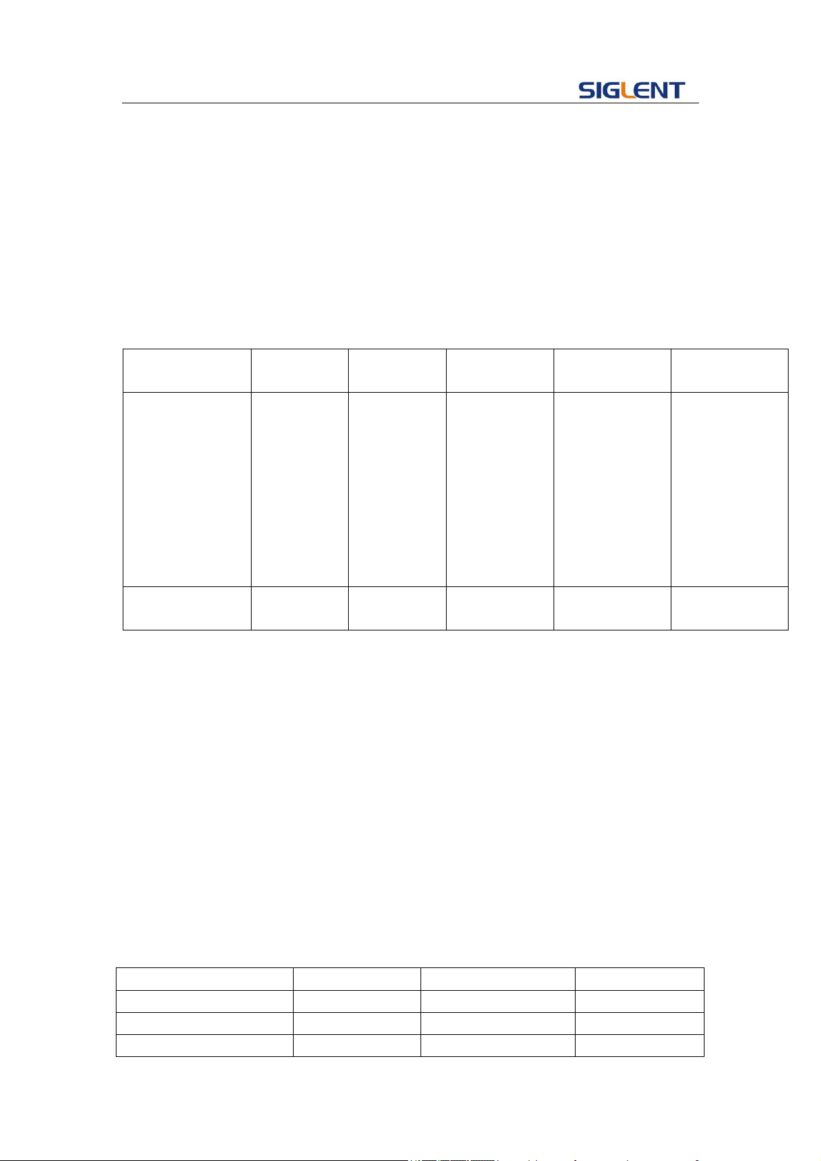
Programming Guide
43
FF\FE\FF\FE\FF\FE\FF\FE\FF\FE\FF\FE\FF\FE\FF\FD\FF\FD\FF\FD\FF\
FD\FF\FD\FF\FD\FF\FD\FF\FD\FF\FC\FF\FC\FF\FC\FF\FC\FF\FC\FF\FC\
FF\FC\FF\FC\FF\FA\FF\FA\FF\FA\FF\FA\FF\FA\FF\FA\FF\FA\FF\FA\FF\
F9\FF\F9\FF\F9\FF\F9\FF\F9\FF\F9\FF\F9\FF\F9\FF\F8\FF\F8\FF\F8\
FF\F8\FF\F8\FF\F8\FF\F8\FF\F8\FF\F7\FF\F7\FF\F7\FF\F7\FF\F7\FF\
F7\FF\F7\FF\F7\FF\F6\FF\F6\FF\F6\FF\F6\FF\F6\FF\F6\FF\F6\FF\F6\
FF\F6\FF\F6\FF\F6\FF\F6\FF\F6\FF\F6\FF\F6\FF\F6\FF\F5\FF\F5\FF\
……
Note:
Parameter/comm
and
SDG800
SDG1000
SDG2000X
SDG5000
SDG1000X
Mn
(0<=n<=59):
M0~M49:
build in
wave
(32KB).
M50~M59:
can store
user defined
wave (32KB)
(0<=n<=59):
M0~M49:
build in
wave
(32KB).
M50~M59:
can store
user defined
wave (32KB)
(0<=n<=196):
M0~M196: all
of them are
building in
waves
(32KB). user
defined waves
have not this
index.
(0<=n<=68):
M0~M35: build
in wave (32KB).
M36~M59:
User define
wave (32KB).
M60~M67:
User defined
wave(1024KB)
(0<=n<=196):
M0~M196: all
of them are
building in
waves (32KB).
user defined
waves have not
this index.
USER
no
no
yes(get user
defined wave)
no
yes(get user
defined wave)
3.23 Virtual Key Command
DESCRIPTION
The Command is used to send simulate a operation of pressing
key on front panel.
COMMAND SYNTAX
VKEY (VirtualKEY) VALUE,<value>,STATE,<sate>
<value>:= {a parameter from the table below.}
<state>:=<0,1>( “1” is effective to virtual value, and “0” is
useless )
EXAMPLE
VKEY VALUE,15, STATE,1
VKEY VALUE,KB_SWEEP, STATE,1
Note:
KB_FUNC1
28
KB_NUMBER_4
52
KB_FUNC2
23
KB_NUMBER_5
53
KB_FUNC3
18
KB_NUMBER_6
54
KB_FUNC4
13
KB_NUMBER_7
55
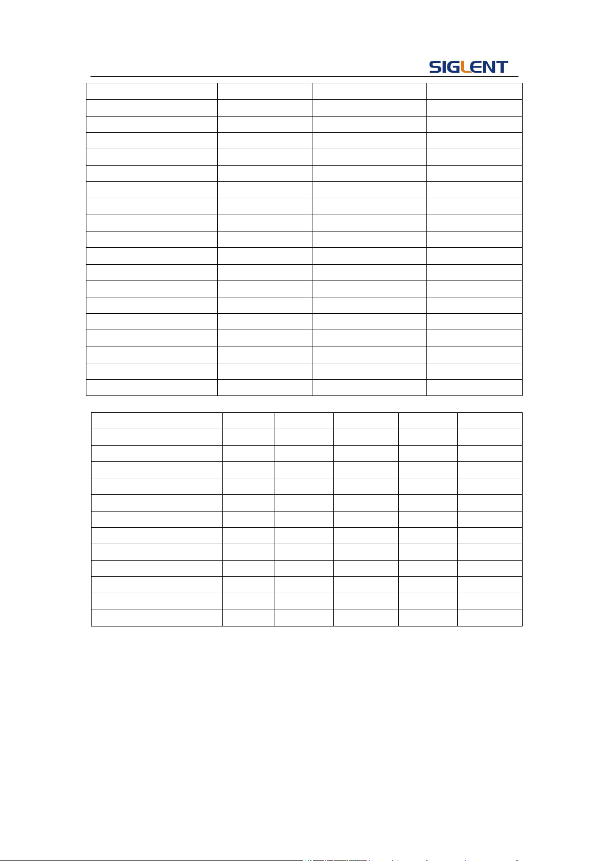
Programming Guide
44
KB_FUNC5
8
KB_NUMBER_8
56
KB_FUNC6
3
KB_NUMBER_9
57
KB_SINE
34
KB_POINT
46
KB_SQUARE
29
KB_NEGATIVE
43
KB_ RAMP
24
KB_LEFT
44
KB_PULSE
19
KB_RIGHT
40
KB_NOISE
14
KB_UP
45
KB_ARB
9
KB_DOWN
39
KB_MOD
15
KB_OUTPUT1
153
KB_SWEEP
16
KB_OUTPUT2
152
KB_BURST
17
KB_KNOB_RIGHT
175
KB_WAVES
4
KB_KNOB_LEFT
177
KB_UTILITY
11
KB_KNOB_DOWN
176
KB_PARAMETER
5
KB_HELP
12
KB_STORE_RECALL
70
KB_CHANNEL
72
KB_NUMBER_0
48
KB_NUMBER_1
49
KB_NUMBER_2
50
KB_NUMBER_3
51
Note:
Parameter/command
SDG800
SDG1000
SDG2000X
SDG5000
SDG1000X
KB_FUNC1
no
no
yes
yes
yes
KB_STORE_RECALL
yes
yes
yes
no
yes
KB_HELP
yes
yes
no
no
no
KB_CHANNEL
no
yes
yes
no
yes
KB_SINE
yes
yes
no
no
no
KB_SQUARE
yes
yes
no
no
no
KB_ RAMP
yes
yes
no
no
no
KB_PULSE
yes
yes
no
no
no
KB_NOISE
yes
yes
no
no
no
KB_ARB
yes
yes
no
no
no
KB_UP
yes
yes
no
no
no
KB_DOWN
yes
yes
no
no
no
3.24 IP Command
DESCRIPTION
The Command can set and get system IP address.
COMMAND SYNTAX
SYST:COMM:LAN:IPAD
(SYSTem:COMMunicate:LAN:IPADdress)
<parameter1>.<parameter2>.<parameter3>.<parameter4>

Programming Guide
45
<parameter1>:={a integer value between 1 and 223}
<parameter2>:={a integer value between 0 and 255}
<parameter3>:={a integer value between 0 and 255}
<parameter4>:={a integer value between 0 and 255}
QUERY SYNTAX
SYST:COMM:LAN:IPAD
(SYSTem:COMMunicate:LAN:IPADdress)?
EXAMPLES Set IP address to 10.11.13.203
SYSTem: COMMunicate: LAN:IPADdress 10.11.13.203
Get IP address.
SYST:COMM:LAN:IPAD?
Return:
“10.11.13.203”
Note:
Parameter/command
SDG800
SDG1000
SDG2000X
SDG5000
SDG1000X
SYST:COMM:LAN:IPAD
no
no
yes
no
yes
3.25 Subnet Mask Command
DESCRIPTION
The Command can set and get system subnet mask.
COMMAND SYNTAX
SYST:COMM:LAN:SMAS (SYSTem:COMMunicate:LAN:SMASk)
<parameter1>.<parameter2>.<parameter3>.<parameter4>
<parameter1>:={a integer value between 0 and 255}
<parameter2>:={a integer value between 0 and 255}
<parameter3>:={a integer value between 0 and 255}
<parameter4>:={a integer value between 0 and 255}
QUERY SYNTAX
SYSTem:COMMunicate:LAN:SMASk?
EXAMPLES Set subnet mask to 255.0.0.0
SYSTem:COMMunicate:LAN:SMASk 255.0.0.0
Get subnet mask
SYSTem:COMMunicate:LAN:SMASk?
Return:
“255.0.0.0”
Note:

Programming Guide
46
Parameter/command
SDG800
SDG1000
SDG2000X
SDG5000
SDG1000X
SYST:COMM:LAN:SMAS
no
no
yes
no
yes
3.26 Gateway Command
DESCRIPTION
The Command can set and get system Gateway.
COMMAND SYNTAX
SYST:COMM:LAN:GAT(SYSTem:COMMunicate:LAN:GATeway)
<parameter1>.<parameter2>.<parameter3>.<parameter4>
<parameter1>:={a integer value between 0 and 223}
<parameter2>:={a integer value between 0 and 255}
<parameter3>:={a integer value between 0 and 255}
<parameter4>:={a integer value between 0 and 255}
QUERY SYNTAX
SYSTem:COMMunicate:LAN:GATeway?
EXAMPLES Set Gateway to 10.11.13.5:
SYSTem:COMMunicate:LAN:GATeway 10.11.13.5
Get gateway:
SYSTem:COMMunicate:LAN:GATeway?
Return:
“10.11.13.5”
Note:
Parameter/command
SDG800
SDG1000
SDG2000X
SDG5000
SDG1000X
SYST:COMM:LAN:GAT
no
no
yes
no
yes
3.27 Sampling Rate Command
DESCRIPTION
Sets or gets sampling rate. You can only use it in TrueArb mode.
COMMAND SYNTAX
<channel>:SRATE(SampleRATE) MODE <parameter1>, VALUE,
<parameter2>
<channel> :=<C1, C2>
<parameter1> :=< DDS, TARB>
<parameter2> :={ a integer value between 1e-6 and 75000000,
(default unit is Sa/s)}

Programming Guide
47
QUERY SYNTAX <channel>: SRATE?
EXAMPLES Get the channel one sample rate value
C1: SRATE?
Return:
C1: SRATE MODE, DDS
Set channel one to TureArb mode.
C1: SRATE MODE, TARB
Set channel one sample rate value to 1000000Sa/s.
C1: SRATE VALUE, 1000000
Note:
Parameter/command
SDG800
SDG1000
SDG2000X
SDG5000
SDG1000X
<channel>
No(single
channel)
yes
yes
yes
yes
SRATE
no
no
yes
no
no
3.28 Harmonic Command
DESCRIPTION
Sets or gets harmonic information. The command can be used
by SDG2000X/SDG1000X.and the channel current basic wave
must be sine.
COMMAND SYNTAX
<channel>:HARM(HARMonic) HARMSTATE,<value1>, HARMTY
PE, < value2>, HARMORDER,< value3>, <parameter>, <value4>,
HARMPHASE, < value5>
< value1>:= <ON, OFF>
< value2>:= <EVEN, ODD, ALL>
< value3>:= {an integer value.}
<parameter> :=< HARMAMP, HARMDBC>
< value4>:= {an integer value.}
< value5>:= {an integer value.}
QUERY SYNTAX <channel>: HARM (HARMonic)?
<channel>:={C1, C2}
EXAMPLES Set the channel one harmonic switch on.
C1: HARMHARMSTATE, ON
Get the channel one harmonic information.

Programming Guide
48
C1: HARM?
Return:
C1:HARM HARMSTATE, ON,HARMTYPE, EVEN,HARMORDER,
2, HARMAMP, 0V, HARMPHASE, 0
Note:
Parameter/command
SDG800
SDG1000
SDG2000X
SDG5000
SDG1000X
HARM
no
no
yes
no
yes
3.29 Waveform Combining Command
DESCRIPTION
Sets or gets waveform combining information. The command can
be used by SDG2000X/SDG1000X.
COMMAND SYNTAX
<channel>:CMBN (CoMBiNe) <parameter>
<channel>:={C1, C2}
<parameter>:= {ON, OFF}
QUERY SYNTAX <channel>: CMBN (CoMBiNe)?
<channel>:={C1, C2}
EXAMPLES Turn on the waveform combining of channel one.
C1:CMBN ON
Query the waveform combining state of channel two.
C2:CMBN?
Return:
C2:CMBN OFF
Note:
Parameter/command
SDG800
SDG1000
SDG2000X
SDG5000
SDG1000X
CMBN
no
no
yes
no
yes

Programming Guide
49
4 Programming Examples
This chapter gives some examples for the programmer. In these examples you can see
how to use the NI-VISA lib and the commands which have been described before this
chapter to control our devices. By the examples’ guide, you can develop more functions
application as you want. This example is developed by Visual Studio project.
Main topics of this part:
Example of Vc++
Example of VB
Example of MATLAB
Example of LabVIEW
4.1 Example of VC++
Environment: Win7 32bit system, Visual Studio
The functions of this example: use the NI-VISA, to control the device with USBTMC or
TCP/IP access to do a write and read.
Follow the steps to finish the example:
1、 Open Visual Studio, create a new VC++ win32 console project.
2、 Set the project environment to use the NI-VISA lib, there are two ways to use
NI-VISA, static or automatic:
2.1 Static: find files: visa.h, visatype.h, visa32.lib in NI-VISA install path. Copy
them to your project, and add them into project. In the projectname.cpp file, add
the follow two lines:
#include "visa.h"
#pragma comment(lib,"visa32.lib")
2.2 Automatic:
Set the .h file include directory, the NI-VISA install path, in our computer we set
the path is : C:\Program Files\IVI Foundation \VISA\WinNT\include. Set this path
to project---properties---c/c++---General---Additional Include Directories: See the
picture.
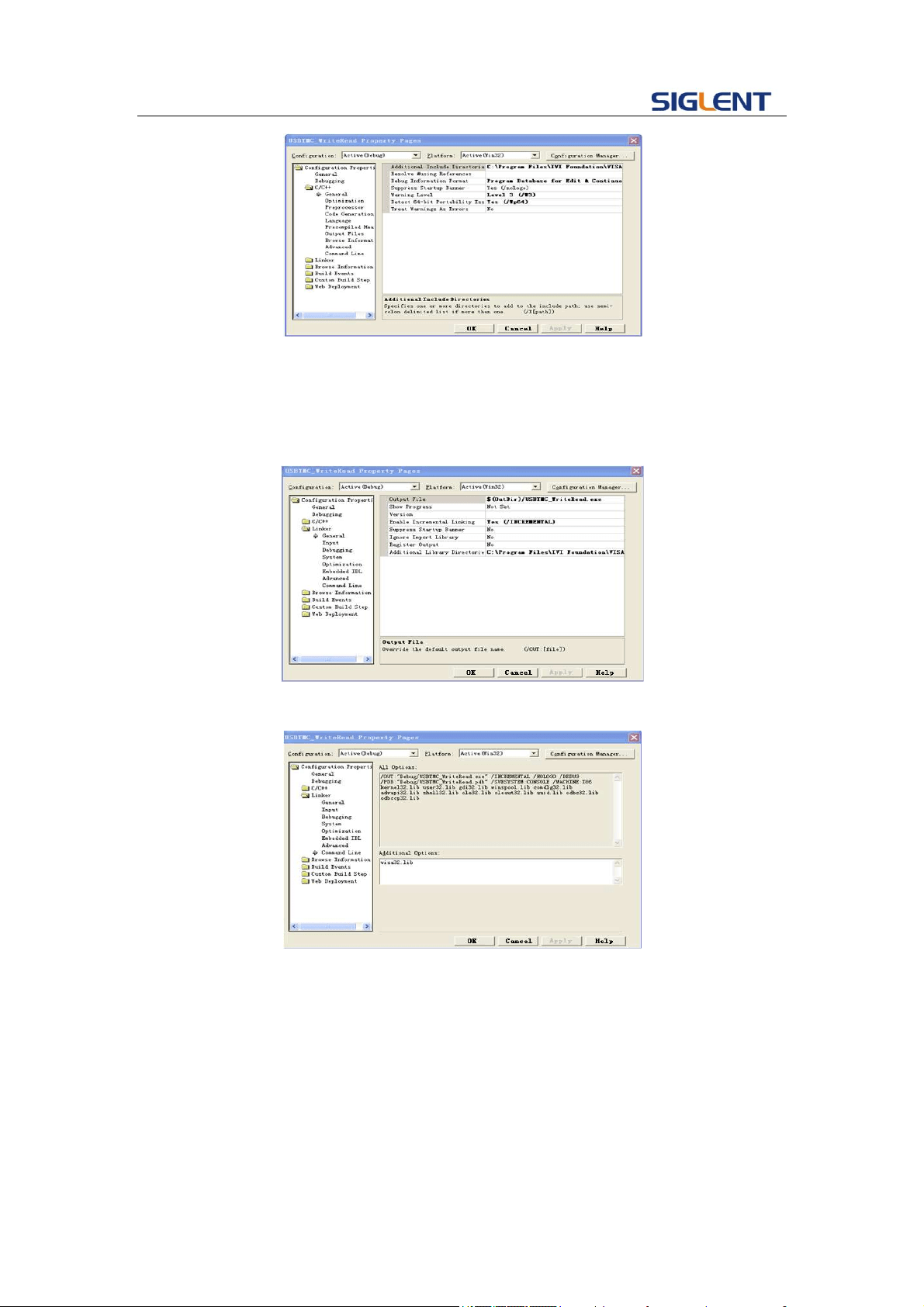
Programming Guide
50
Set lib path set lib file:
Set lib path: the NI-VISA install path, in our computer we set the path is :
C:\Program Files\IVI Foundation\VISA\WinNT
\lib\msc. Set this path to project---properties---Linker---General---Additional
Library Directories: as seen in the pictures below.
Set lib file:project---properties---Linker---Command Line---Additional Options:
visa32.lib
Include visa.h file: In the projectname.cpp file:
#include <visa.h>
3、 Add codes:
3.1 USBTMC access code.
Write a function Usbtmc_test:
int Usbtmc_test()
{
/* This code demonstrates sending synchronous read & write commands */

Programming Guide
51
/* to an USB Test & Measurement Class (USBTMC) instrument using */
/* NI-VISA */
/* The example writes the "*IDN?\n" string to all the USBTMC */
/* devices connected to the system and attempts to read back */
/* results using the write and read functions. */
/* The general flow of the code is */
/* Open Resource Manager */
/* Open VISA Session to an Instrument */
/* Write the Identification Query Using viPrintf */
/* Try to Read a Response With viScanf */
/* Close the VISA Session */
/***********************************************************/
ViSession defaultRM;
ViSession instr;
ViUInt32 numInstrs;
ViFindList findList;
ViUInt32 retCount;
ViUInt32 writeCount;
ViStatus status;
char instrResourceString[VI_FIND_BUFLEN];
unsigned char buffer[100];
char stringinput[512];
int i;
/** First we must call viOpenDefaultRM to get the manager
* handle. We will store this handle in defaultRM.*/
status=viOpenDefaultRM (&defaultRM);
if (status<VI_SUCCESS)
{
printf ("Could not open a session to the VISA Resource Manager!\n");

Programming Guide
52
return status;
}
/* Find all the USB TMC VISA resources in our system and store the number of resources in the system
in numInstrs. */
status = viFindRsrc (defaultRM, "USB?*INSTR", &findList, &numInstrs, instrResourceString);
if (status<VI_SUCCESS)
{
printf ("An error occurred while finding resources.\nHit enter to continue.");
fflush(stdin);
getchar();
viClose (defaultRM);
return status;
}
/** Now we will open VISA sessions to all USB TMC instruments.
* We must use the handle from viOpenDefaultRM and we must
* also use a string that indicates which instrument to open. This
* is called the instrument descriptor. The format for this string
* can be found in the function panel by right clicking on the
* descriptor parameter. After opening a session to the
* device, we will get a handle to the instrument which we
* will use in later VISA functions. The AccessMode and Timeout
* parameters in this function are reserved for future
* functionality. These two parameters are given the value VI_NULL.*/
for (i=0; i<numInstrs; i++)
{
if (i> 0)
viFindNext (findList, instrResourceString);
status = viOpen (defaultRM, instrResourceString, VI_NULL, VI_NULL, &instr);
if (status<VI_SUCCESS)

Programming Guide
53
{
printf ("Cannot open a session to the device %d.\n", i+1);
continue;
}
/* * At this point we now have a session open to the USB TMC instrument.
* We will now use the viPrintf function to send the device the string "*IDN?\n",
* asking for the device's identification. */
char * cmmand ="*IDN?\n";
status = viPrintf (instr, cmmand);
if (status<VI_SUCCESS)
{
printf ("Error writing to the device %d.\n", i+1);
status = viClose (instr);
continue;
}
/** Now we will attempt to read back a response from the device to
* the identification query that was sent. We will use the viScanf
* function to acquire the data.
* After the data has been read the response is displayed.*/
status = viScanf(instr, "%t", buffer);
if (status<VI_SUCCESS)
printf ("Error reading a response from the device %d.\n", i+1);
else
printf ("\nDevice %d: %s\n", i+1 , buffer);
status = viClose (instr);
}
/** Now we will close the session to the instrument using
* viClose. This operation frees all system resources. */
status = viClose (defaultRM);

Programming Guide
54
system("pause"); // pause to keep off the console flashed.
return 0;
}
Result:
3.2 TCP/IP access code.
Write a function TCP_IP_Test:
int TCP_IP_Test(char *pIP)
{
char outputBuffer[VI_FIND_BUFLEN];
ViSession defaultRM, instr;
ViStatus status;
ViUInt32 count;
ViUInt16 portNo;
/* First we will need to open the default resource manager. */
status = viOpenDefaultRM (&defaultRM);
if (status<VI_SUCCESS)
{
printf("Could not open a session to the VISA Resource Manager!\n");
}
/* Now we will open a session via TCP/IP device */
char head[256] ="TCPIP0::";
char tail[] ="::INSTR";
char resource [256];
strcat(head,pIP);
strcat(head,tail);
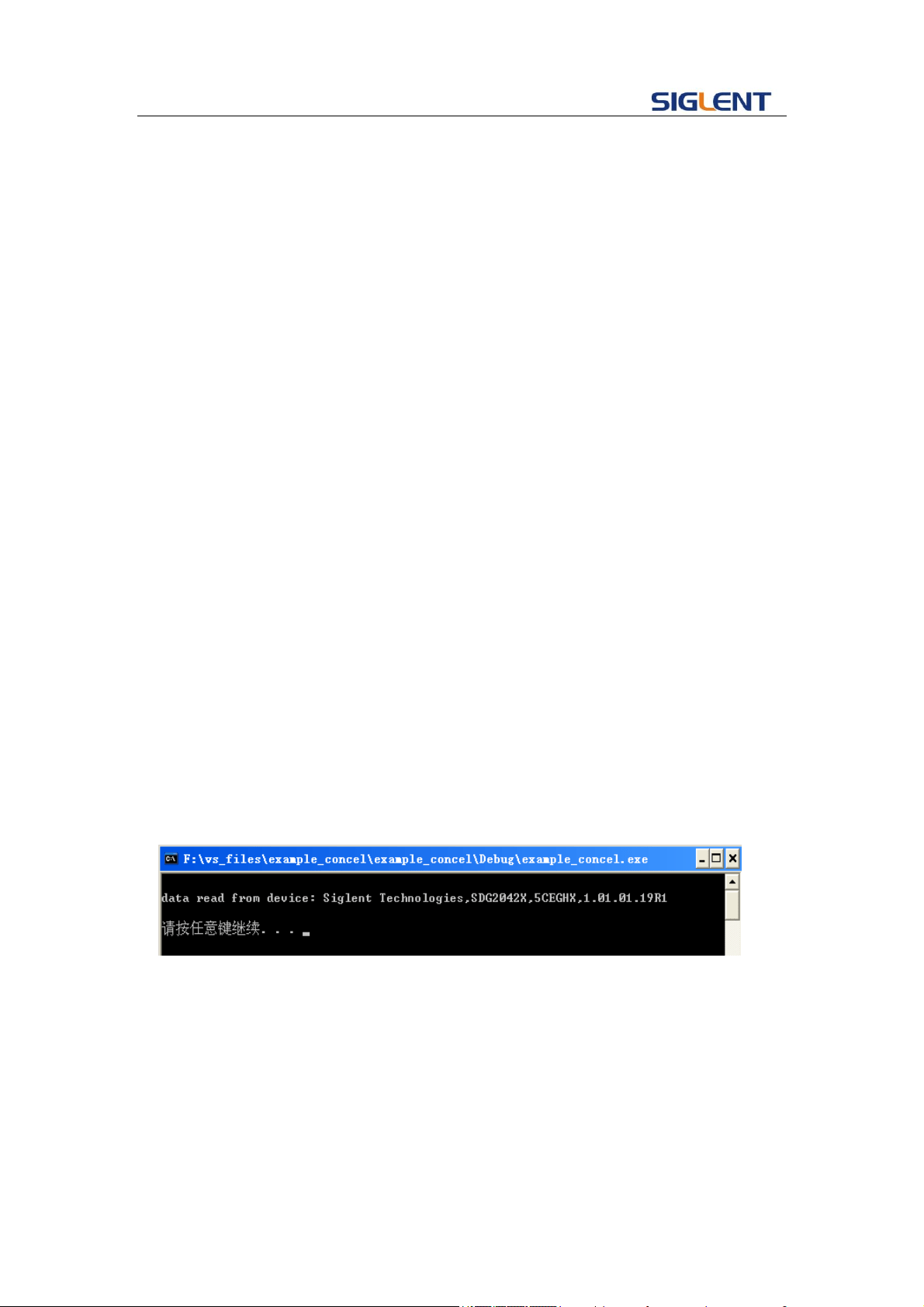
Programming Guide
55
status = viOpen (defaultRM, head, VI_LOAD_CONFIG, VI_NULL, &instr);
if (status<VI_SUCCESS)
{
printf ("An error occurred opening the session\n");
viClose(defaultRM);
}
status = viPrintf(instr, "*idn?\n");
status = viScanf(instr, "%t", outputBuffer);
if (status<VI_SUCCESS)
{
printf("viRead failed with error code: %x \n",status);
viClose(defaultRM);
}else
printf ("\ndata read from device: %*s\n", 0,outputBuffer);
status = viClose (instr);
status = viClose (defaultRM);
system("pause");
return 0;
}
Run result.
4.2 Example of VB
Environment: Win7 32bit system, Microsoft Visual Basic 6.0
The function of this example: Use the NI-VISA, to control the device with USBTMC
and TCP/IP access to do a write and read.
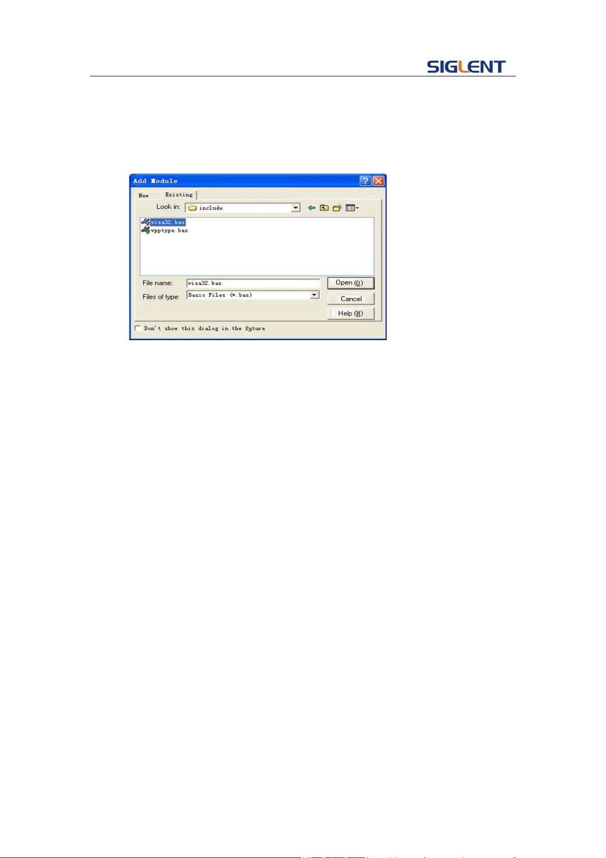
Programming Guide
56
Follow the steps to complete the example:
1. Open Visual Basic, build a standard application program project (Standard EXE)
2. Set the project environment to use the NI-VISA lib, Click the Existing tab of
Project>>Add Existing Item. Search for the visa32.bas file in the include folder
under the NI-VISA installation path and add the file.
This allows the VISA functions and VISA data types to be used in a program.
3. Add codes:
3.1、USBTMC access code.
Write a function Usbtmc_test:
Private Function Usbtmc_test() As Long
' This code demonstrates sending synchronous read & write commands
' to an USB Test & Measurement Class (USBTMC) instrument using
' NI-VISA
' The example writes the "*IDN?\n" string to all the USBTMC
' devices connected to the system and attempts to read back
' results using the write and read functions.
' The general flow of the code is
' Open Resource Manager
' Open VISA Session to an Instrument
' Write the Identification Query Using viWrite
' Try to Read a Response With viRead
' Close the VISA Session
Const MAX_CNT = 200

Programming Guide
57
Dim defaultRM As Long
Dim instrsesn As Long
Dim numlnstrs As Long
Dim findList As Long
Dim retCount As Long
Dim writeCount As Long
Dim status As Long
Dim instrResourceString As String * VI_FIND_BUFLEN
Dim Buffer As String * MAX_CNT
Dim i As Integer
' First we must call viOpenDefaultRM to get the manager
' handle. We will store this handle in defaultRM.
status = viOpenDefaultRM(defaultRM)
If (status < VI_SUCCESS) Then
resultTxt.Text = "Could not open a session to the VISA Resource Manager!"
Usbtmc_test = status
Exit Function
End If
' Find all the USB TMC VISA resources in our system and store the
' number of resources in the system in numInstrs.
status = viFindRsrc(defaultRM, "USB?*INSTR", findList, numlnstrs, instrResourceString)
If (status < VI_SUCCESS) Then
resultTxt.Text = "An error occurred while finding resources."
viClose (defaultRM)
Usbtmc_test = status
Exit Function
End If

Programming Guide
58
' Now we will open VISA sessions to all USB TMC instruments.
' We must use the handle from viOpenDefaultRM and we must
' also use a string that indicates which instrument to open. This
' is called the instrument descriptor. The format for this string
' can be found in the function panel by right clicking on the
' descriptor parameter. After opening a session to the
' device, we will get a handle to the instrument which we
' will use in later VISA functions. The AccessMode and Timeout
' parameters in this function are reserved for future
' functionality. These two parameters are given the value VI_NULL.
For i = 0 To numInstrs
If (i > 0) Then
status = viFindNext(findList, instrResourceString)
End If
status = viOpen(defaultRM, instrResourceString, VI_NULL, VI_NULL, instrsesn)
If (status < VI_SUCCESS) Then
resultTxt.Text = "Cannot open a session to the device " + CStr(i + 1)
GoTo NextFind
End If
' At this point we now have a session open to the USB TMC instrument.
' We will now use the viWrite function to send the device the string "*IDN?",
' asking for the device's identification.
status = viWrite(instrsesn, "*IDN?", 5, retCount)
If (status < VI_SUCCESS) Then
resultTxt.Text = "Error writing to the device."
status = viClose(instrsesn)
GoTo NextFind

Programming Guide
59
End If
' Now we will attempt to read back a response from the device to
' the identification query that was sent. We will use the viRead
' function to acquire the data.
' After the data has been read the response is displayed.
status = viRead(instrsesn, Buffer, MAX_CNT, retCount)
If (status < VI_SUCCESS) Then
resultTxt.Text = "Error reading a response from the device." + CStr(i + 1)
Else
resultTxt.Text = "Read from device: " + CStr(i + 1) + " " + Buffer
End If
status = viClose(instrsesn)
NextFind:
Next i
' Now we will close the session to the instrument using
' viClose. This operation frees all system resources.
status = viClose(defaultRM)
Usbtmc_test = 0
End Function
3.2、TCP/IP access code.
Write a function TCP_IP_Test:
Private Function TCP_IP_Test(ip As String) As Long
Dim outputBuffer As String * VI_FIND_BUFLEN
Dim defaultRM As Long
Dim instrsesn As Long
Dim status As Long
Dim count As Long

Programming Guide
60
' First we will need to open the default resource manager.
status = viOpenDefaultRM(defaultRM)
If (status < VI_SUCCESS) Then
resultTxt.Text = "Could not open a session to the VISA Resource Manager!"
TCP_IP_Test = status
Exit Function
End If
' Now we will open a session via TCP/IP device
status = viOpen(defaultRM, "TCPIP0::" + ip + "::INSTR", VI_LOAD_CONFIG, VI_NULL, instrsesn)
If (status < VI_SUCCESS) Then
resultTxt.Text = "An error occurred opening the session"
viClose (defaultRM)
TCP_IP_Test = status
Exit Function
End If
status = viWrite(instrsesn, "*IDN?", 5, count)
If (status < VI_SUCCESS) Then
resultTxt.Text = "Error writing to the device."
End If
status = viRead(instrsesn, outputBuffer, VI_FIND_BUFLEN, count)
If (status < VI_SUCCESS) Then
resultTxt.Text = "Error reading a response from the device." + CStr(i + 1)
Else
resultTxt.Text = "read from device:" + outputBuffer
End If
status = viClose(instrsesn)

Programming Guide
61
status = viClose(defaultRM)
TCP_IP_Test = 0
End Function
3.3、Button control code:
Private Sub exitBtn_Click()
End
End Sub
Private Sub tcpipBtn_Click()
Dim stat As Long
stat = TCP_IP_Test(ipTxt.Text)
If (stat < VI_SUCCESS) Then
resultTxt.Text = Hex(stat)
End If
End Sub
Private Sub usbBtn_Click()
Dim stat As Long
stat = Usbtmc_test
If (stat < VI_SUCCESS) Then
resultTxt.Text = Hex(stat)
End If
End Sub
3.4、Run result:
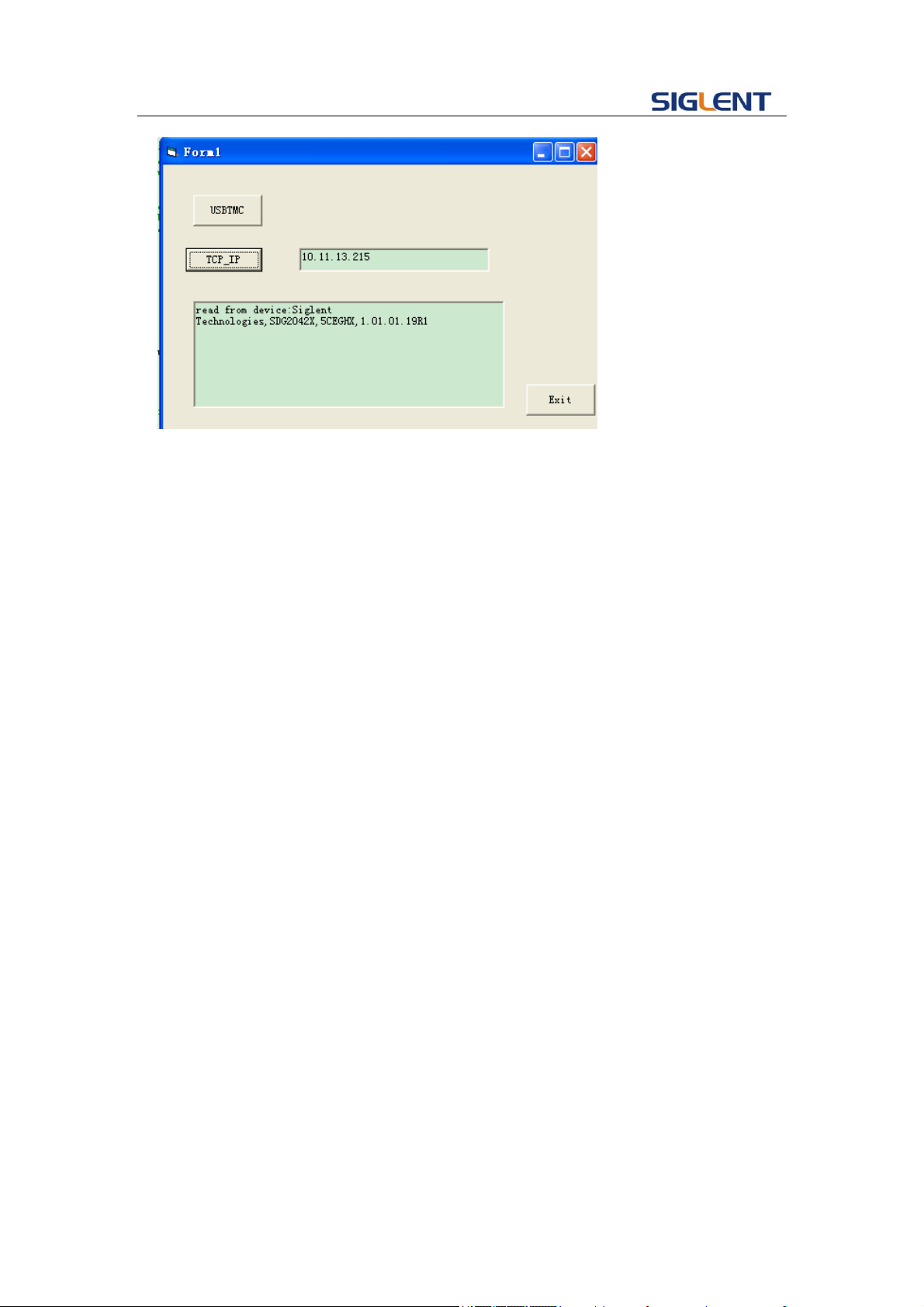
Programming Guide
62
4.3 Example of MATLAB
Environment: Win7 32bit system, MATLAB R2010b
The function of this example: Use the NI-VISA, to control the device with USBTMC or
TCP/IP access to do a write and read.
Follow the steps to complete the example:
Open MATLAB, modify the current directory. In this demo, the current directory is
modified to D:\USBTMC_TCPIP_Demo.
Click File>>New>>Script in the Matlab interface to create an empty M file
Add codes:
1.1 Write a function Usbtmc_test.
function USBTMC_test()
% This code demonstrates sending synchronous read & write commands
% to an USB Test & Measurement Class (USBTMC) instrument using
% NI-VISA
%Create a VISA-USB object connected to a USB instrument
vu = visa('ni','USB0::0xF4EC::0xEE38::0123456789::INSTR');
%Open the VISA object created
fopen(vu);
%Send the string "*IDN?",asking for the device's identification.
fprintf(vu,'*IDN?');
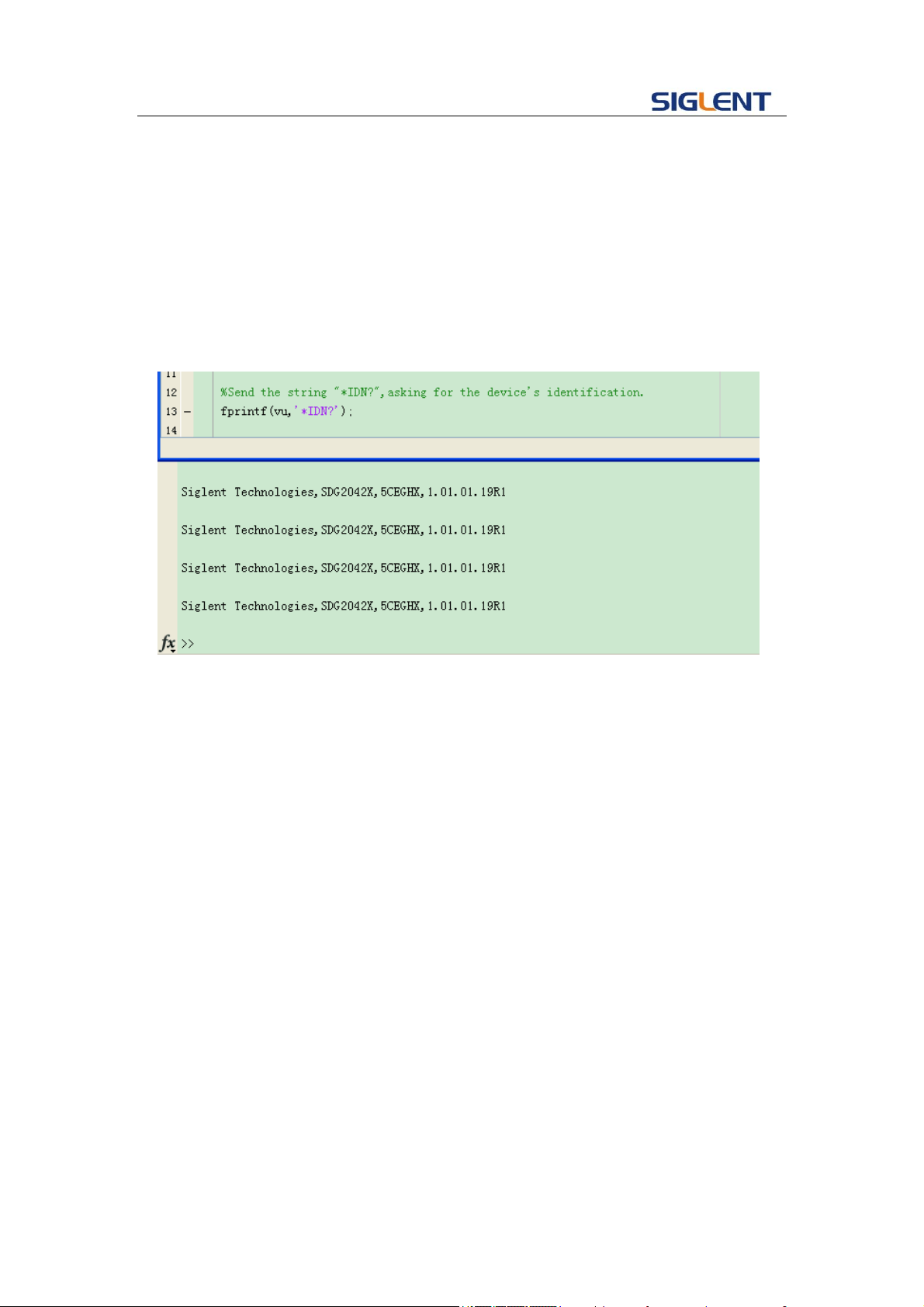
Programming Guide
63
%Request the data
outputbuffer = fscanf(vu);
disp(outputbuffer);
%Close the VISA object
fclose(vu);
delete(vu);
clear vu;
end
1.2 TCP/IP access code.
Write a function TCP_IP_Test:
function TCP_IP_test( IPstr )
% This code demonstrates sending synchronous read & write commands
% to an TCP/IP instrument using NI-VISA
%Create a VISA-TCPIP object connected to an instrument
%configured with IP address.
vt = visa('ni',['TCPIP0::',IPstr,'::INSTR']);
%Open the VISA object created
fopen(vt);
%Send the string "*IDN?",asking for the device's identification.
fprintf(vt,'*IDN?');
%Request the data
outputbuffer = fscanf(vt);
disp(outputbuffer);
%Close the VISA object
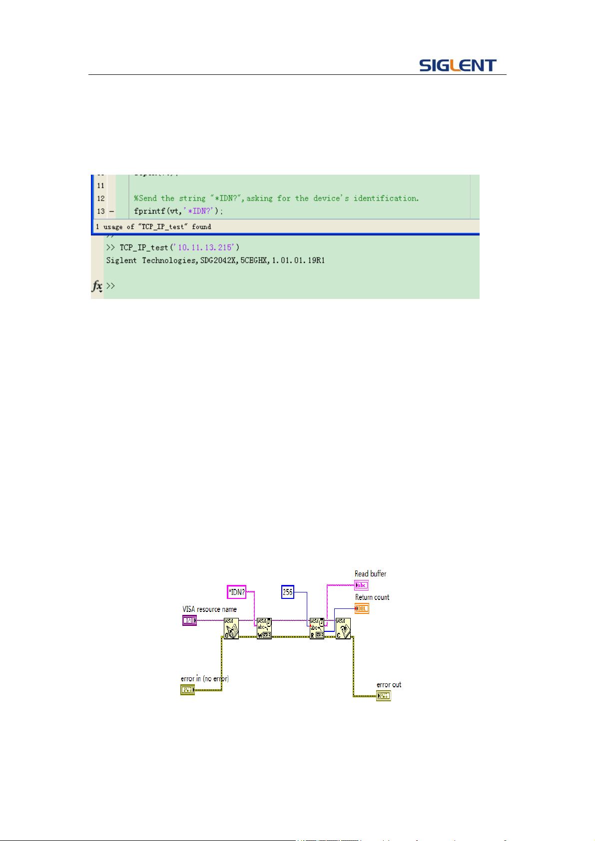
Programming Guide
64
fclose(vt);
delete(vt);
clear vt;
end
4.4 Example of LabVIEW
Environment: Win7 32bit system, LabVIEW 2011
The functions of this example: use the NI-VISA, to control the device with USBTMC
and TCP/IP access to do a write and read.
Follow the steps to complete the example:
1、 Open LabVIEW, create a VI file.
2、 Add controls. Right-click in the Front Panel interface, select and add VISA
resource name, error in, error out and some indicators from the Controls column.
3、 Open the Block Diagram interface. Right-click on the VISA resource name and
you can select and add the following functions from VISA Palette from the pop-up
menu: VISA Write, VISA Read, VISA Open and VISA Close.
4、 Connect them as shown in the figure below
5、 Select the device resource from the VISA Resource Name list box and run the
program.
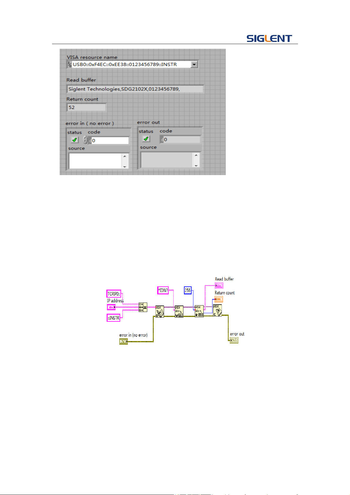
Programming Guide
65
In this example, the VI opens a VISA session to a USBTMC device, writes a
command to the device, and reads back the response. In this example, the specific
command being sent is the device ID query. Check with your device manufacturer for
the device command set. After all communication is complete, the VI closes the VISA
session.
6、Communicating with the device via TCP/IP is similar to USBTMC. But you need to
change VISA Write and VISA Read Function to Synchronous I/O. The LabVIEW
default is asynchronous I/O. Right-click the node and select Synchronous I/O
Mod>>Synchronous from the shortcut menu to write or read data synchronously.
7、 Connect them as shown in the figure below
8、 Input the IP address and run the program.
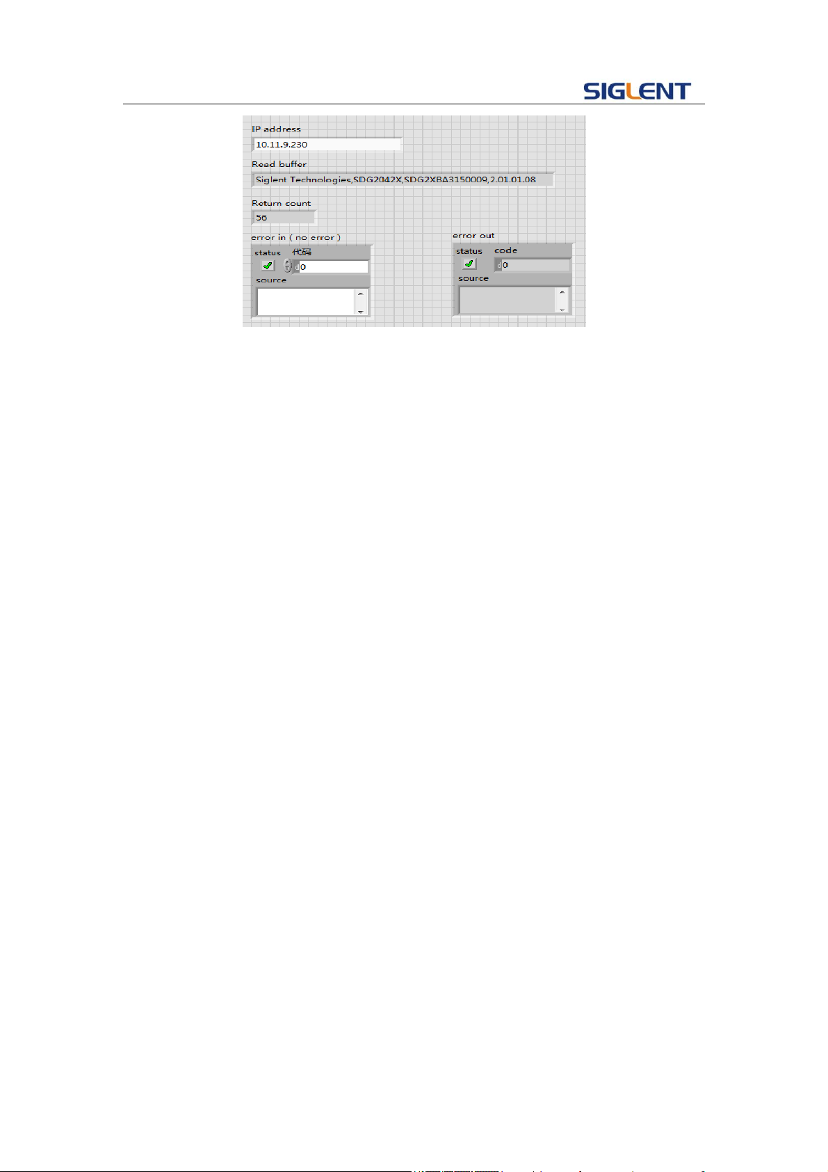
Programming Guide
66
Note: you can obtain the source code of above examples, please visit SIGLENT
website at www.siglent.com.

Programming Guide
67
5 Index
*IDN
OPC
*CLS
*ESE
*ESR
*RST
*SRE
*STB
*TST
*WAI
DDR
CMR
A
ARWV ARBWAVE
B
BSWV BASIC_WAVE
BTWV BURSTWAVE
BUZZ BUZZER
C
CHDR COMM_HEADER
COUP COUPLING
CMBN COMBINE
F
FCNT FREQCOUNTER
H
HARM HARMONIC
I
IVNT INVERT
L
LAGG LANGUAGE
M
MDWV MODULATEWAVE

Programming Guide
68
N
NBFM NUMBER_FORMAT
O
OUTP OUTPUT
P
PACP PARACOPY
R
ROSC ROSCILLATOR
S
SCFG Sys_CFG
SCSV SCREEN_SAVE
SWWV SWEEPWAVE
SYNC SYNC
STL STORELIST
SYST:COMM:LAN:IPAD SYSTEM:COMMUNICATE:LAN:IPADDRESS
SYST:COMM:LAN:SMAS SYSTem:COMMunicate:LAN:SMASk
SYST: COMM: LAN:GAT SYSTem:COMMunicate:LAN:GATeway
SRATE SAMPLERATE
W
WVDT WVDT
V
VOLTPRT VOLTPRT
VKEY VIRTUALKEY