
754532-100 Rev. 3 3/19
1
THANK YOU...
for selecting an American Standard bath. Your new bath is shipped to you after careful inspection. The whirlpool
and air bath versions are completely assembled with pump/blower and system piping. All you need to finish the
installation are your selected fittings and electrical connections.
To ensure maximum performance and pleasure from this product, please follow the instructions and cautions.
For questions or service issues, please call Technical Support 1-(800)-442-1902.
Please do not contact or return product to the store.
MODEL 2742
MODEL 2748
MODEL 2806
MODEL 2903
MODEL 2932
MODEL 2934
MODEL 2938
MODEL 2940
MODEL 3571
MODEL 3572
MODEL 3573
MODEL 3574
MODEL 3575
MODEL 3581
INSTALLATION AND
OPERATION MANUAL
BATHTUBS, WHIRLPOOLS, AIR BATHS
AND COMBINATION TUBS WITH
OPTIONAL CHROMATHERAPY
© AS America, Inc. 2019
All product names listed herein are trademarks of AS America, Inc. unless otherwise noted.

2
754532-100 Rev. 3 3/19
TABLE OF CONTENTS:
Safety Instructions Notice.................................................................Page 3
Installation, Framing and Post Installation
Clean-Up Instructions.......................................................................Page 4
Roughing-in References for Recess Type Installations.....................Page 5
Roughing-in References for Pier Type Installations...........................Page 6
Under Deck Mounting Instructions....................................................Page 6
Roughing-in References for All Model Series...................................Page 7
Electrical Installation Instructions
.....................................................Page 18
Whirlpool Heater Operation
......
..........................................................Page 23
Remote Air Blower Location Option..................................................Page 24
Operation: Single Speed Whirlpool...................................................Page 26
Operation: EcoSilent Whirlpool with Lights.......................................Page 27
Operation: Air Bath............................................................................Page 28
Operation: Air Bath with Lights..........................................................Page 29
Operation: Combination Tub with Lights...........................................Page 31
Cleaning and Maintenence...............................................................Page 33
Warranty
......................................
.....................................................Page 34

754532-100 Rev. 3 3/19
3
IMPORTANT SAFETY
INSTRUCTIONS
READ AND FOLLOW ALL INSTRUCTIONS!
!
!
!
!
!
!
WARNING:
Risk of personal injury.
Do not permit children to use this bathtub without adult supervision. Never drop
or insert any object into any opening. Do not operate this unit without the guard over the suction fitting.
WARNING:
Risk of electric shock.
Do not permit electrical appliances near any bathtub when bathtub contains water.
WARNING:
Risk of hyperthermia and possible drowning.
People using medications and/or having adverse
medical history should consult a physician before using this product.
WARNING: Risk of personal injury. Do not overfill bathtub before entering. Entering tub when filled more than 2/3 can
cause overflow and slippery conditions. Exercise caution when entering and exiting.
WARNING:
No Food or Alcoholic Beverages.
Use of your bathtub immediately after meals is not recommended.
Avoid alcohol consumption before or during bathing. Alcoholic beverages can cause drowsiness or hyperthermia resulting in
loss of consciousness or even drowning.
WARNING:
Pregnancy.
If you are or think you may be pregnant, consult your physician before using the bathtub.
Use this unit only for its intended use as described in this manual.
Do not use any attachments not recommended by American Standard.
The unit must be connected only to a supply circuit that is properly protected by a ground-fault circuit-interrupter (GFCI).
Such a GFCI should be provided by the installer and should be tested on a routine basis. To test the GFCI, push the test
button. The GFCI should interrupt power. Push the reset button. Power should be restored. If the GFCI fails to operate in this
manner, the GFCI is defective. If the GFCI interrupts power to the bathtub without the test button being pushed, a ground
current is flowing, indicating the possibility of an electric shock. Do not use this air bath. Disconnect the air bath and have
the problem corrected by a licensed electrician before using.
SAVE THESE INSTRUCTIONS

4
754532-100 Rev. 3 3/19
Each bath arrives ready for installation, completely equipped with the pump/blower electronics
and plumbing necessary for operation. However, a drain/overflow kit is required for each bath
and it is not included.
The variety of installations for this bath may require framing procedures other than those shown.
Locate studs as required. Ensure roughing-in dimensions are proper, plumb, and square.
Installation and Framing Instructions
Remove the bath from the carton. Retain the shipping carton until satisfactory
inspection of the product has been made. Do not lift the bath by the plumbing at
any time; handle by the shell only.
All bath units are factory tested for proper operation and watertight connections
prior to shipping. Prior to installation, the bath must be filled with water and
operated to check for leaks that may have resulted from shipping damage or
mishandling.
The sumps of these baths are supported by feet and no additional sump
support is required. Once the bath is in place, the feet should be shimmed and
secured accordingly so that the rim of the bath contacts the stringer or pier but
supports no weight.
Provisions must be made in all installations for an access opening for servicing the
bath pump/blower. Unless an access opening of at least 12" x 24" (305mm x 610mm)
is provided, warranty service will not be performed. It is strongly recommended that an
additional opening be provided for access to drain components.
Each bath has a nominal length (L), width (W), and Height (H) along with a rim
height. Unless otherwise noted in the following rough-in references, assume
that the nominal tolerances are as much as +/-1/4 inch (6mm). Therefore, it is
strongly recommended that the installer build the surrounding structure after
receiving the actual bath. Structural measurements should be verified against
the actual bath received to ensure proper fit.
!
!
!
!
!
POST INSTALLATION CLEAN-UP
Remove all construction debris from bath. Tile grout can be removed with a wooden
popsicle stick or tongue depressor.
Do not use wire brushes or any other metal implement on bath surface.
Post installation clean-up generally can be completed using warm water and liquid
dishwashing detergent.
Stubborn dirt or stains may be removed using granular Spic and Span
®
mixed with water.
Painter's naphtha can be used to remove excess adhesives and/or wet oil-base paint.
754532-100 Rev. 3 3/19
5
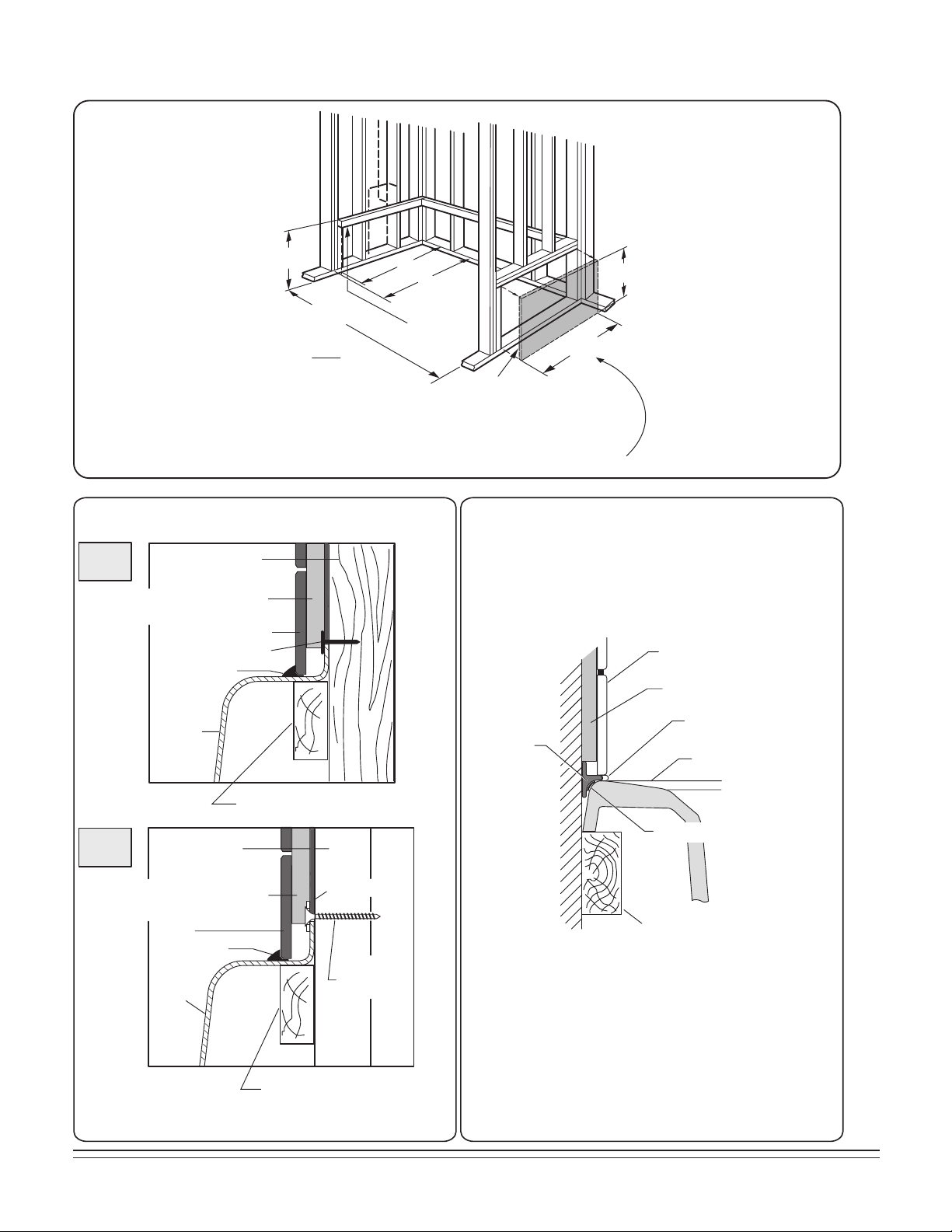
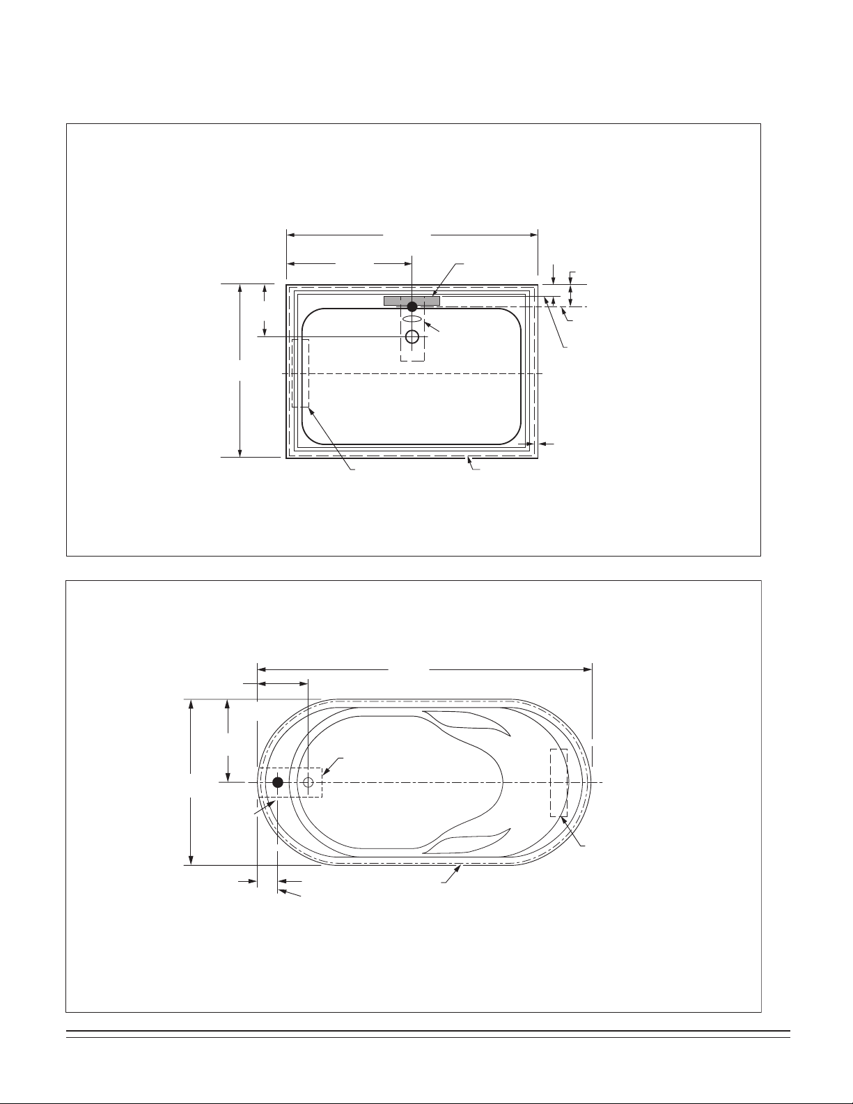
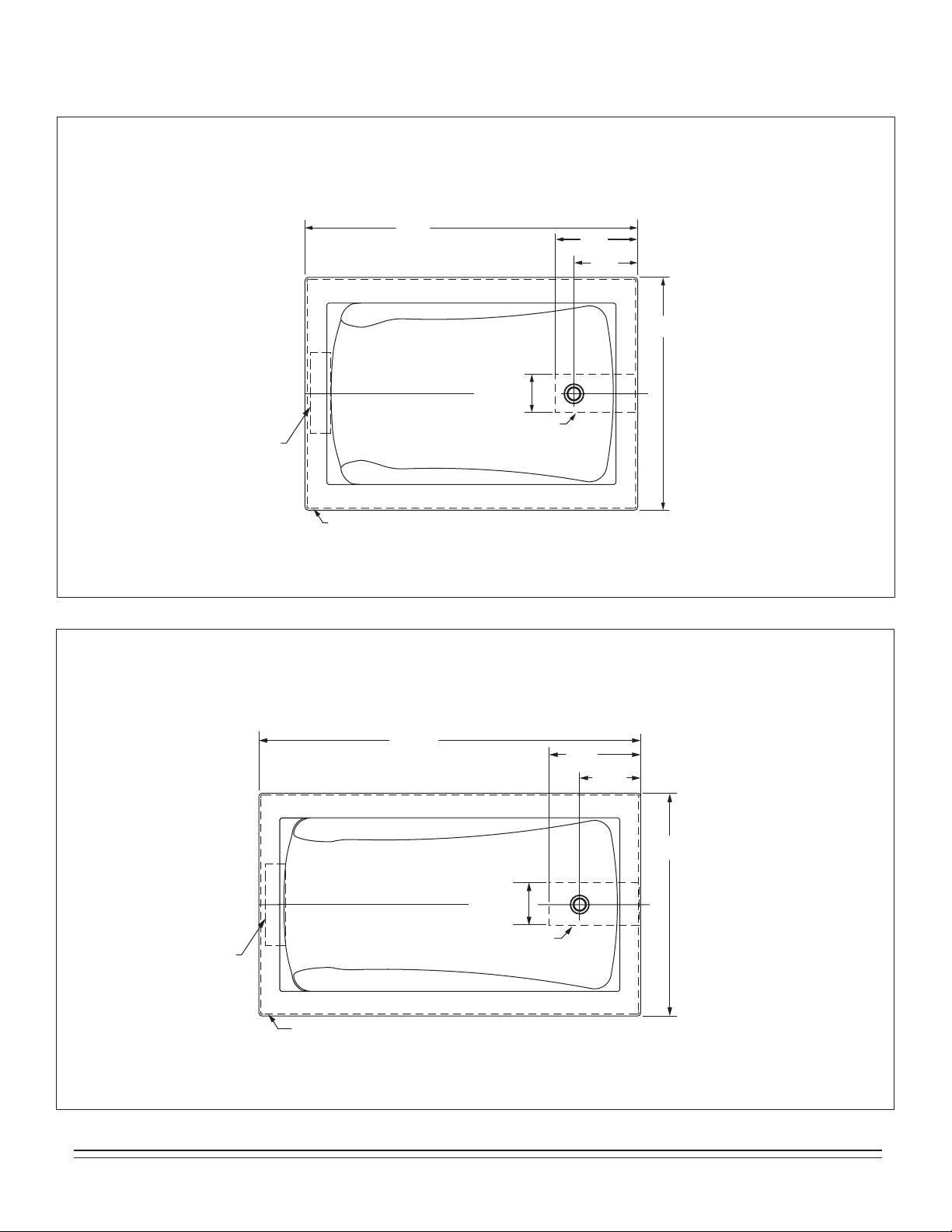
ROUGH-IN REFERENCES FOR RECESS TYPE INSTALLATIONS
TILE
TILE
BEAD
STRIP
LEVELING STRINGER
1" x 4" (25mm x 102mm) not for support
BATH
ADHESIVE
SEALANT
WALLBOARD
NOTE: Tile bead kit not included and must
be purchased separately.
SECURE THE BATH TO THE STUDS AS SHOWN
FOR WOOD OR STEEL STUD CONSTRUCTION.
TYPICAL TILE FLANGE INSTALLATION
TYPICAL TILE BEAD INSTALLATION
STUD
WATERPROOF DRYWALL
OR CEMENT BOARD
WATERPROOF DRYWALL
OR CEMENT BOARD
TILE
SEALANT
TUB
ROOFING NAIL
1" x 3" (25 x 76mm) WOOD
STRINGER FULL LENGTH
1" x 3" (25 x 76mm) WOOD
STRINGER FULL LENGTH
STEEL
STUD
WASHER
TILE
SEALANT
TUB
4" (102mm)
DRYWALL
SCREW
STEEL
STUDS
WOOD
STUDS
24"
(610 mm)
12"
(305 mm)
C
E
D
W
LEVELING
STRINGERS
ACCESS PANEL MUST BE LOCATED
ON THE SAME SIDE AS THE MOTOR.
ALLOW OPEN FRAMING ON
PUMP/MOTOR END FOR SERVICE.
UNLESS AN ACCESS OPENING OF AT LEAST 12" x 24" (305 x 610mm)
IS PROVIDED, WARRANTY SERVICE WILL NOT BE PERFORMED.
NOTE:
FRONT EDGE
OF BATH MUST
BE SUPPORTED
BY STUD WALL OR
AMERICAN STANDARD
APRON KIT
ACCESS PANELS NOT
REQUIRED FOR BATH TUBS
6
754532-100 Rev. 3 3/19
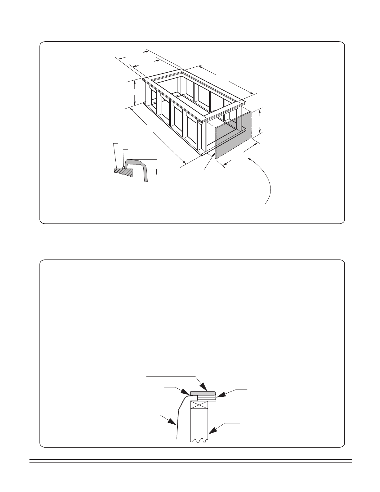
Please note that care must be taken to protect the surface of the tub during all aspects of the installation.
Do not drill or cut the bath deck with the tub directly beneath it as damage to the tub may result.
1. Install the tub per the installation instructions provided with the unit.
2. Prepare the bath deck support structure per the local codes. Note - the bath deck must be self supporting.
3. Cut bath deck to your specifications.
4. Place the bath deck in position and trace the opening on the tub with a soft pencil. Do not drill or cut the bath
deck with the tub directly beneath it as damage to the tub may result.
5. Remove the bath deck and apply a generous bead of waterproof sealant on the outer edge of the traced line.
6. Replace the bath deck and secure it into place.
7. Apply additional sealant along the tub and bath deck interface as necessary to ensure a watertight seal.
8. Remove excess sealant per the manufacturer's instructions.
Finished bath deck surface material must be
self-supporting and secured per local codes
Tub support structure per installation
instructions provided with the tub
Bath deck support material
Bathtub
Waterproof
Sealant
UNDER DECK MOUNTING INSTRUCTIONS
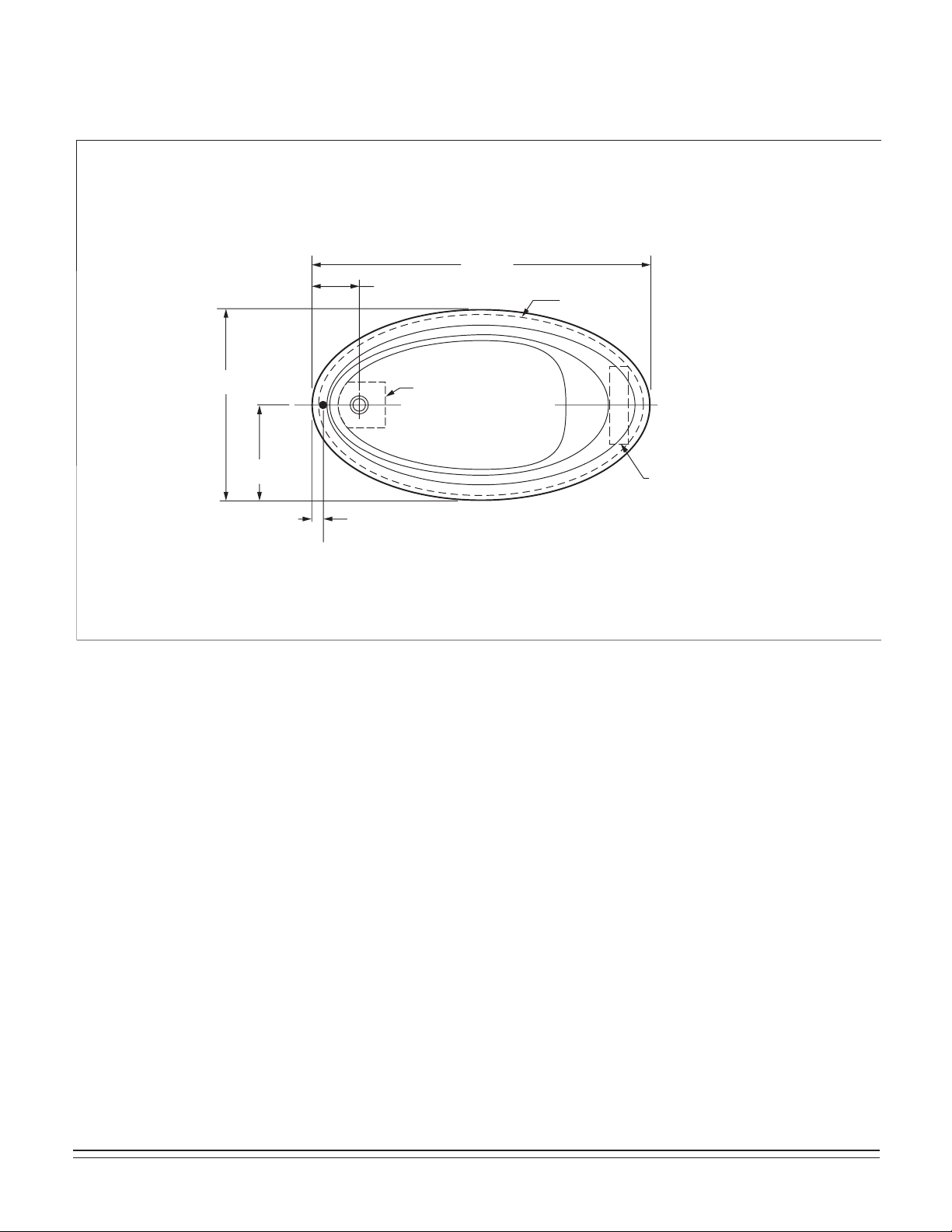
ROUGH-IN REFERENCES FOR PIER TYPE INSTALLATIONS
AS DESIRED
F
CUTOUT
AS DESIRED
G
CUTOUT
C
24"
(610 mm)
12"
(305 mm)
MOUNTING
SURFACE
WATERPROOF
SEALANT
BATH
ACCESS PANEL MUST BE LOCATED
ON THE SAME SIDE AS THE MOTOR.
ALLOW OPEN FRAMING ON
PUMP/MOTOR END FOR SERVICE.
ACCESS PANELS NOT REQUIRED
FOR BATH TUBS
UNLESS AN ACCESS OPENING OF AT LEAST 12" X 24" (305 X 610mm)
IS PROVIDED, WARRANTY SERVICE WILL NOT BE PERFORMED.
754532-100 Rev. 3 3/19
7
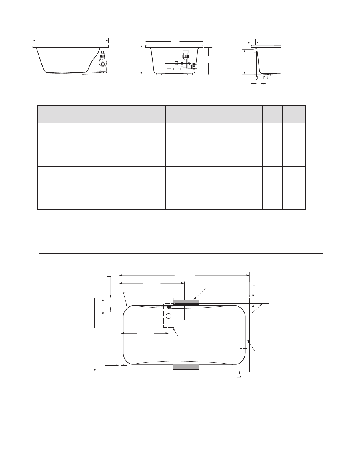
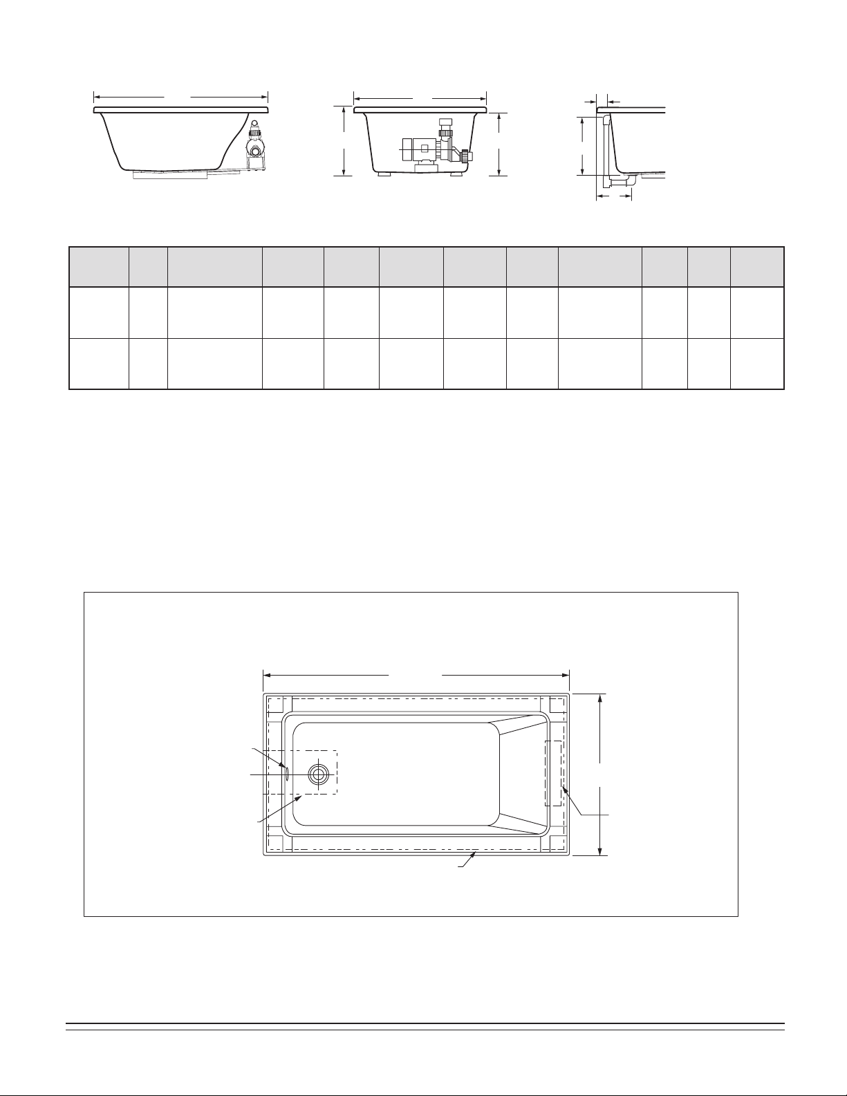
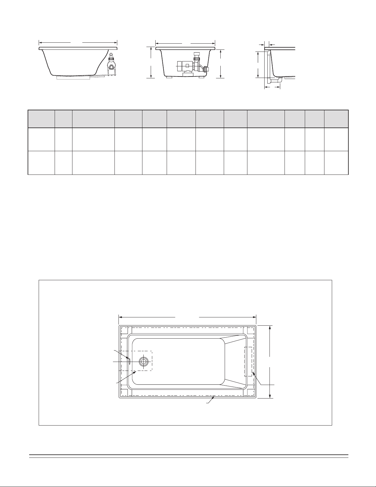
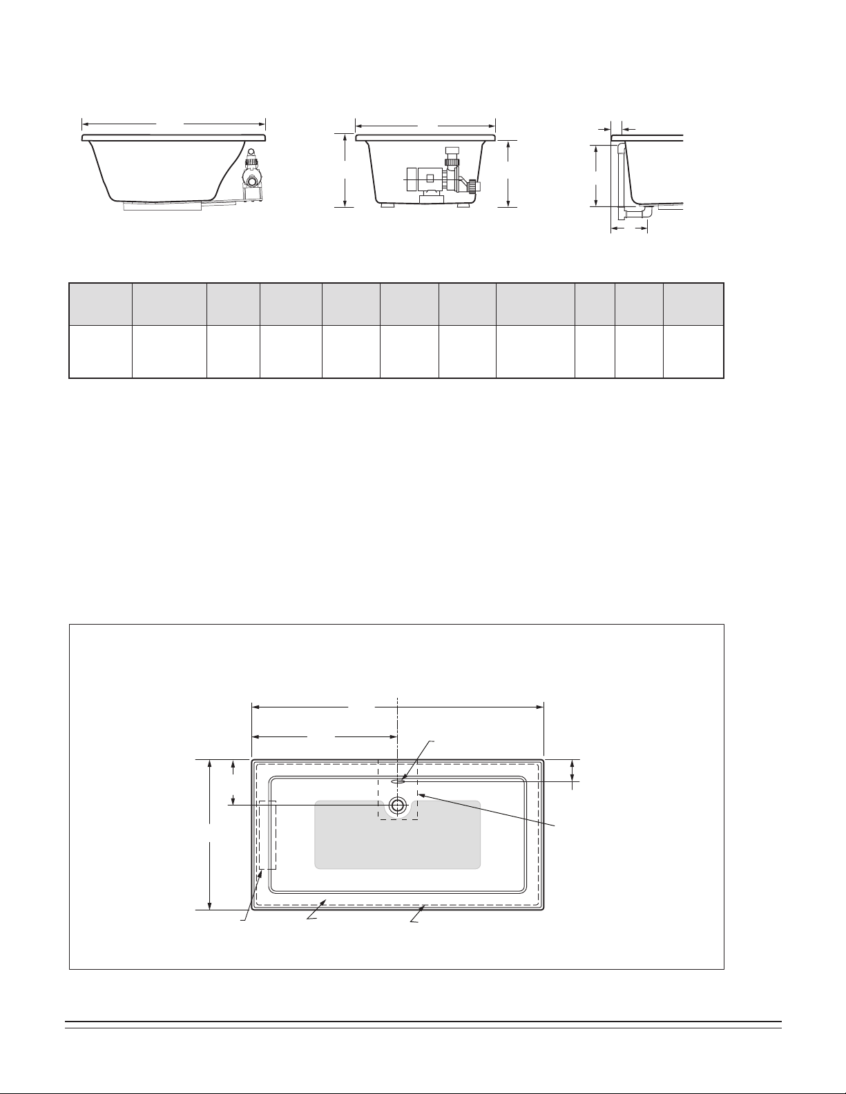
SPECIFICATIONS:
GENERAL SPECIFICATIONS FOR WHIRLPOOLS AND BATH TUBS
SIDE VIEW
DRAIN / OVERFLOW
END VIEW
L
H
W
C
A
B
J
A 16-1/4"
(413mm)
B 13-1/4"
(337mm)
A 14-1/2"
(368mm)
B 14-1/2"
(368mm)
A 17"
(432mm)
B 11"
(279mm)
A 17"
(432mm)
B 9-1/2"
(241mm)
4"
(102mm)
5-1/4"
(133mm)
5-1/2"
(140mm)
3"
(76mm)
C 20"
(508mm)
C 21"
(533mm)
C 19-1/2"
(495mm)
C 19-1/4"
(489mm)
70"
(1778mm)
x 40-1/4"
(1022mm)
58"
(1473mm)
x 40-1/8"
(1019mm)
Template
Provided
Template
Provided
71-11/16"
(1821mm)
x 40-1/4"
(1022mm)
59-11/16"
(1517mm)
x 40-1/8"
(1019mm)
As Desired
As Desired
L 71-1/2" (1816mm)
W 41-3/4" (1060mm)
H 22" (559mm)
L 59-1/2" (1511mm)
W 41-5/8" (1057mm)
H 23" (584mm)
L 72" (1829mm)
W 35-3/4" (908mm)
H 21-1/2" (546mm)
L 60" (1524mm)
W 42-1/4" (1073mm)
H 21-1/4" (540mm)
115 lb.
(52 kg.)
110 lb.
(50 kg.)
135 lb.
(61 kg.)
107 lb.
(49 kg.)
690 lb. (313 kg)/
33 lb./sq.ft.
(161 kg/sq.m)
611 lb. (277 kg)/
40 lb./sq.ft.
(196 kg/sq.m)
744 lb. (338 kg)/
41 lb./sq.ft.
(200 kg/sq.m)
640 lb. (291 kg)/
35 lb./sq.ft.
(171 kg/sq.m)
69 gal.
(261 l.)
60 gal.
(227 l.)
73 gal.
(276 l.)
64 gal.
(242 l.)
60 gal.
(227 l.)
55 gal.
(208 l.)
44 gal.
(166 l.)
53 gal.
(200 l.)
Description
Drain /
Overflow
Cut Out
Pier
G x F
Rough-In
Recess
E x D
Tub Edge to
Centerline
Overflow: J
Weight with
Water / Floor
Loading
Product
Weight
Gallon to
Overflow
Whirlpool
Operating
Volume
Height to
Underside of
Deck Edge: C
Dimensions
L-W-H
2742
Town Square
6' x 42"
2748
Town Square
5' x 42"
2806
Heritage Oval
6' x 36"
2903
Savona Oval
5' x 42"
TABLE 1
MODEL SERIES 2742
41-3/4"
(1060mm)
26-3/4"
(679mm)
C/L OF DRAIN OUTLET
71-1/2"
(1816mm)
35-3/4"
(908mm)
13-1/4"
(337mm)
4"
(102mm)
3"
(76mm)
FLOOR CUTOUT
5" X 15"
(127 X 381mm)
OUTLINE OF CUTOUT
70" X 40-1/4"
(1778 X 1022mm)
INTEGRAL
FITTING DECK
3" x 14"
(76 x 356mm)
3/4"
(19mm)
EDGE
OF FLOOR
CUTOUT
PROVIDE ACCESS
TO PUMP
SERVING ON
ALL INSTALLATIONS
ROUGH-IN REFERENCES
8
754532-100 Rev. 3 3/19
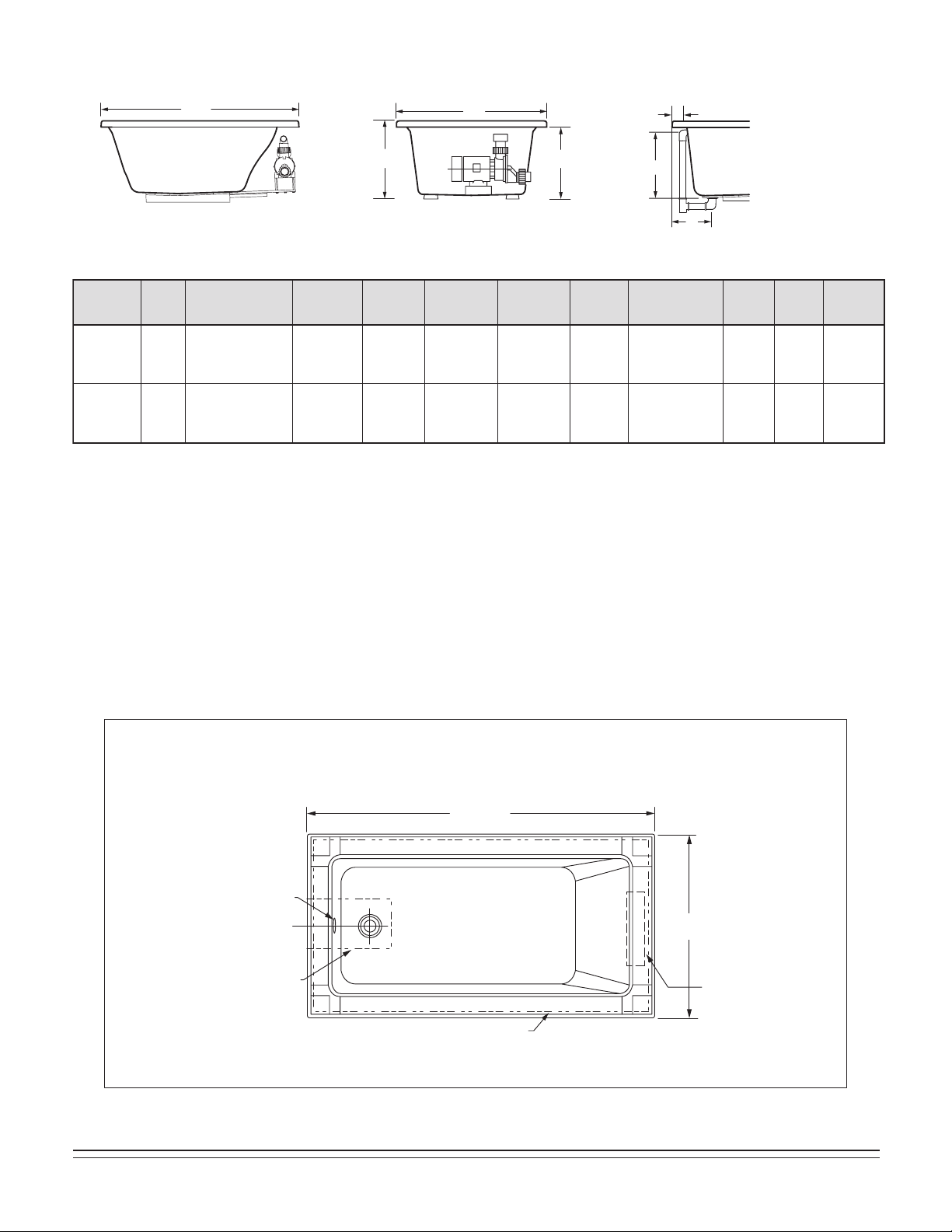
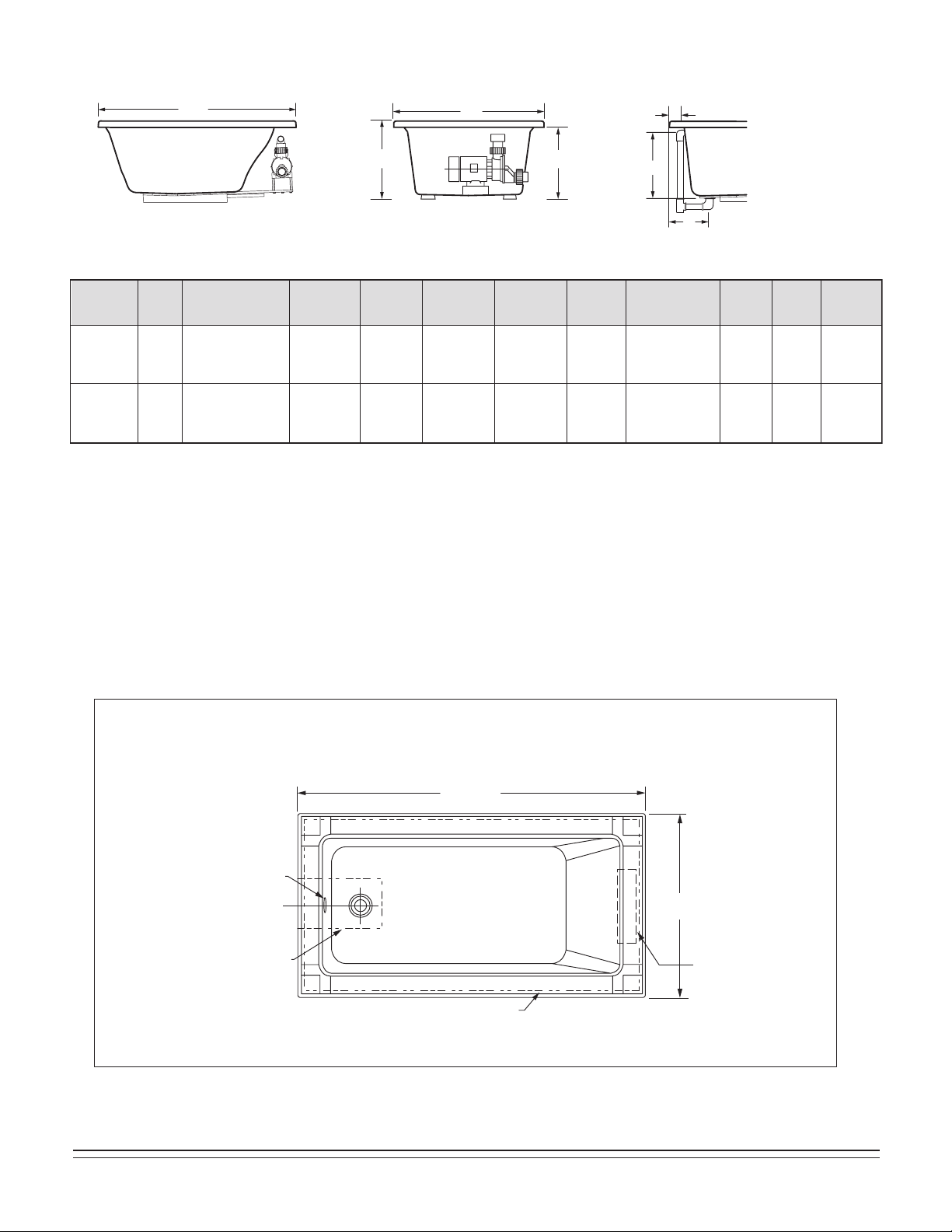
ROUGH-IN REFERENCES
MODEL SERIES 2748
59-1/2"
(1511mm)
INTEGRAL
FITTING DECK
3" X 14"
(76 X 356mm)
29-7/8"
(759mm)
41-5/8"
(1057mm)
OUTLINE OF CUTOUT
58-1/4" X 40-1/4"
(1480 X 1022mm)
C/L OF
DRAIN
OUTLET
FLOOR CUTOUT
5" X 12"
(127 X 305mm)
3/4"
(19mm)
14-1/2"
(368mm)
5-1/4"
(133mm)
3"
(76mm)
EDGE OF
FLOOR
CUTOUT
PROVIDE ACCESS
TO PUMP
SERVING ON
ALL INSTALLATIONS
INTEGRAL
FITTING
DECK
72"
(1829mm)
9" x 13"
(229 x 330mm)
FLOOR CUTOUT
11"
(279mm)
35-3/4"
(908mm)
18"
(457mm)
5-1/2"
(140mm)
C/L OF DRAIN
OVERFLOW
OUTLINE
OF CUTOUT
MODEL SERIES 2806
PROVIDE ACCESS
TO PUMP
SERVING ON
ALL INSTALLATIONS
754532-100 Rev. 3 3/19
9
OUTLINE OF
CUTOUT - USE
TEMPLAT E
9-1/2"
(241mm)
42-1/4"
(1073mm)
21-1/8"
(537mm)
3"
(76mm)
60"
(1524mm)
C
L
OF DRAIN
OUTLET
12" (305mm) X 9"(229mm)
CUTOUT IN FLOOR FOR DRAIN
ROUGH-IN REFERENCES
MODEL SERIES 2903
PROVIDE ACCESS
TO PUMP
SERVING ON
ALL INSTALLATIONS
10
754532-100 Rev. 3 3/19
SPECIFICATIONS:
GENERAL SPECIFICATIONS FOR STUDIO 5' x 32" WHIRLPOOLS AND BATH TUBS
SIDE VIEW
DRAIN / OVERFLOW
END VIEW
L
H
W
C
A
B
J
A 17-3/4"
(451mm)
B 10-3/4"
(273mm)
A 17-3/4"
(451mm)
B 10-7/8"
(276mm)
C 21-7/8"
(556mm)
C 20-1/2"
(521mm)
58"
(1473mm)
x 30"
(762mm)
58-1/4"
(1480mm)
x 30-1/4"
(768mm)
59-11/16"
(1516mm)
x 30"
(762mm)
59-15/16"
(1522mm)
x 30-1/4"
(768mm)
3-1/4"
(83mm)
3-1/4"
(83mm)
L 59-1/2" (1511mm)
W 31-1/2" (800mm)
H 22-1/2" (572mm)
L 59-3/4" (1518mm)
W 31-3/4" (806mm)
H 22-1/2" (572mm)
90 lb.
(198 kg.)
90 lb.
(198 kg.)
581 lb. (264 kg)/
44 lb./sq.ft.
(213 kg/sq.m)
581 lb. (264 kg)/
44 lb./sq.ft.
(213 kg/sq.m)
59 gal.
(224 l.)
59 gal.
(224 l.)
54 gal.
(205 l.)
54 gal.
(205 l.)
Description
Drain /
Overflow
Cut Out
Pier
G x F
Rough-In
Recess
E x D
Tub Edge to
Centerline
Overflow: J
Zero
(5/8")
2"
Deck
Trim
Option
Weight with
Water / Floor
Loading
Product
Weight
Gallon to
Overflow
Whirlpool
Operating
Volume
Height to
Underside of
Deck Edge: C
Dimensions
L-W-H
2932
Studio
5' x 32"
2932
Studio
5' x 32"
TABLE 2
ROUGH-IN REFERENCES
MODEL SERIES 2932
60" NOMINAL
(1524mm)
32" NOMINAL
(813mm)
C/L DRAIN
OUTLINE OF
CUTOUT
9" x 15"
(229 x 305mm)
DRAIN ASS’Y
FLOOR CUTOUT
OVERFLOW
PROVIDE ACCESS
TO PUMP
SERVING ON
ALL INSTALLATIONS
754532-100 Rev. 3 3/19
11
SPECIFICATIONS:
GENERAL SPECIFICATIONS FOR STUDIO 5' x 36" WHIRLPOOLS AND BATH TUBS
SIDE VIEW
DRAIN / OVERFLOW
END VIEW
L
H
W
C
A
B
J
A 17-3/4"
(451mm)
B 10-3/4"
(273mm)
A 17-3/4"
(451mm)
B 10-7/8"
(276mm)
C 21-7/8"
(556mm)
C 20-1/2"
(521mm)
58"
(1473mm)
x 34"
(864mm)
58-1/4"
(1480mm)
x 34-1/4"
(870mm)
59-11/16"
(1516mm)
x 34"
(864mm)
59-15/16"
(1522mm)
x 34-1/4"
(870mm)
L 59-1/2" (1511mm)
W 35-1/2" (902mm)
H 22-1/2" (572mm)
L 59-3/4" (1518mm)
W 35-3/4" (908mm)
H 22-1/2" (572mm)
95 lb.
(209 kg.)
95 lb.
(209 kg.)
686 lb. (311 kg)/
46 lb./sq.ft.
(223 kg/sq.m)
686 lb. (311 kg)/
46 lb./sq.ft.
(223 kg/sq.m)
71 gal.
(269 l.)
71 gal.
(269 l.)
64 gal.
(243 l.)
64 gal.
(243 l.)
Description
Drain /
Overflow
Cut Out
Pier
G x F
Rough-In
Recess
E x D
Tub Edge to
Centerline
Overflow: J
Zero
(5/8")
2"
Deck
Trim
Option
Weight with
Water / Floor
Loading
Product
Weight
Gallon to
Overflow
Whirlpool
Operating
Volume
Height to
Underside of
Deck Edge: C
Dimensions
L-W-H
2934
Studio
5' x 36"
2934
Studio
5' x 36"
TABLE 3
ROUGH-IN REFERENCES
MODEL SERIES 2934
9" x 15"
(229 x 305mm)
DRAIN ASS’Y
FLOOR CUTOUT
60" NOMINAL
(1524mm)
36" NOMINAL
(914mm)
C/L DRAIN
OVERFLOW
OUTLINE OF
CUTOUT
PROVIDE ACCESS
TO PUMP
SERVING ON
ALL INSTALLATIONS
3-1/4"
(83mm)
3-1/4"
(83mm)
12
754532-100 Rev. 3 3/19
SPECIFICATIONS:
GENERAL SPECIFICATIONS FOR STUDIO 5-1/2' x 36" WHIRLPOOLS AND BATH TUBS
SIDE VIEW
DRAIN / OVERFLOW
END VIEW
L
H
W
C
A
B
J
A 17-3/4"
(451mm)
B 10-3/4"
(273mm)
A 17-3/4"
(451mm)
B 10-7/8"
(276mm)
C 21-7/8"
(556mm)
C 20-1/2"
(521mm)
64"
(1626mm)
x 34"
(864mm)
64-1/4"
(1632mm)
x 34-1/4"
(870mm)
65-11/16"
(1668mm)
x 34"
(864mm)
65-15/16"
(1675mm)
x 34-1/4"
(870mm)
L 65-1/2" (1664mm)
W 35-1/2" (902mm)
H 22-1/2" (572mm)
L 65-3/4" (1670mm)
W 35-3/4" (908mm)
H 22-1/2" (572mm)
100 lb.
(220 kg.)
100 lb.
(220 kg.)
766 lb. (348 kg)/
46 lb./sq.ft.
(227 kg/sq.m)
766 lb. (348 kg)/
46 lb./sq.ft.
(227 kg/sq.m)
80 gal.
(303 l.)
80 gal.
(303 l.)
73 gal.
(277 l.)
73 gal.
(277 l.)
Description
Drain /
Overflow
Cut Out
Pier
G x F
Rough-In
Recess
E x D
Tub Edge to
Centerline
Overflow: J
Zero
(5/8")
2"
Deck
Trim
Option
Weight with
Water / Floor
Loading
Product
Weight
Gallon to
Overflow
Whirlpool
Operating
Volume
Height to
Underside of
Deck Edge: C
Dimensions
L-W-H
2938
Studio
5-1/2' x 36"
2938
Studio
5-1/2' x 36"
TABLE 4
ROUGH-IN REFERENCES
MODEL SERIES 2938
9" x 15"
(229 x 305mm)
DRAIN ASS’Y
FLOOR CUTOUT
66" NOMINAL
(1676mm)
36" NOMINAL
(914mm)
C/L DRAIN
OVERFLOW
OUTLINE OF
CUTOUT
PROVIDE ACCESS
TO PUMP
SERVING ON
ALL INSTALLATIONS
3-1/4"
(83mm)
3-1/4"
(83mm)
754532-100 Rev. 3 3/19
13
SPECIFICATIONS:
GENERAL SPECIFICATIONS FOR STUDIO 6' x 36" WHIRLPOOLS AND BATH TUBS
SIDE VIEW
DRAIN / OVERFLOW
END VIEW
L
H
W
C
A
B
J
A 17-3/4"
(451mm)
B 10-3/4"
(273mm)
A 17-3/4"
(451mm)
B 10-7/8"
(276mm)
C 21-7/8"
(556mm)
C 20-1/2"
(521mm)
70"
(1778mm)
x 34"
(864mm)
70-1/4"
(1784mm)
x 34-1/4"
(870mm)
71-11/16"
(1821mm)
x 34"
(864mm)
71-15/16"
(1827mm)
x 34-1/4"
(870mm)
L 71-1/2" (1816mm)
W 35-1/2" (902mm)
H 22-1/2" (572mm)
L 71-3/4" (1822mm)
W 35-3/4" (908mm)
H 22-1/2" (572mm)
105 lb.
(231 kg.)
105 lb.
(231 kg.)
846 lb. (384 kg)/
47 lb./sq.ft.
(230 kg/sq.m)
846 lb. (384 kg)/
47 lb./sq.ft.
(230 kg/sq.m)
89 gal.
(337 l.)
89 gal.
(337 l.)
81 gal.
(307 l.)
81 gal.
(307 l.)
Description
Drain /
Overflow
Cut Out
Pier
G x F
Rough-In
Recess
E x D
Tub Edge to
Centerline
Overflow: J
Zero
(5/8")
2"
Deck
Trim
Option
Weight with
Water / Floor
Loading
Product
Weight
Gallon to
Overflow
Whirlpool
Operating
Volume
Height to
Underside of
Deck Edge: C
Dimensions
L-W-H
2940
Studio
6' x 36"
2940
Studio
6' x 36"
TABLE 5
ROUGH-IN REFERENCES
MODEL SERIES 2940
72" NOMINAL
(1829mm)
36" NOMINAL
(914mm)
C/L DRAIN
OUTLINE OF
CUTOUT
9" x 15"
(229 x 305mm)
DRAIN ASS’Y
FLOOR CUTOUT
OVERFLOW
PROVIDE ACCESS
TO PUMP
SERVING ON
ALL INSTALLATIONS
3-1/4"
(83mm)
3-1/4"
(83mm)
14
754532-100 Rev. 3 3/19
SPECIFICATIONS:
GENERAL SPECIFICATIONS FOR GREEN TEA WHIRLPOOLS AND BATH TUBS
SIDE VIEW
DRAIN / OVERFLOW
END VIEW
L
H
W
C
A
B
J
A 16"
(406mm)
B 11-1/2"
(349mm)
A 16"
(406mm)
B 11-1/2"
(349mm)
A 16"
(406mm)
B 11-1/2"
(349mm)
A 16"
(406mm)
B 11-1/2"
(349mm)
A 16"
(40mm)
B 11-1/2"
(349mm)
3-1/2"
(89mm)
3-3/4"
(95mm)
3-1/2"
(89mm)
3-1/8"
(79mm)
3-1/2"
(89mm)
C 19"
(483mm)
C 19"
(483mm)
C 19"
(483mm)
C 19"
(483mm)
C 19"
(483mm)
58-1/2"
(1485mm)
x 34-1/2"
(876mm)
64-1/2"
(1638mm)
x 34-1/2"
(876mm)
70-1/2"
(1791mm)
x 34-1/2"
(876mm)
58-1/2"
(1485mm)
x 40-1/2"
(1029mm)
70-1/2"
(1791mm)
x 40-1/2"
(1029mm)
60-3/16"
(1529mm)
x 34-1/2"
(876mm)
66-3/16"
(1681mm)
x 34-1/2"
(876mm)
72-3/16"
(1834mm)
x 34-1/2"
(876mm)
60-3/16"
(1528mm)
x 40-1/2"
(1029mm)
72-3/16"
(1834mm)
x 40-1/2"
(1029mm)
L 60" (1524mm)
W 36" (914mm)
H 21" (533mm)
L 66" (1676mm)
W 36" (914mm)
H 21" (533mm)
L 72" (1829mm)
W 36" (914mm)
H 21" (533mm)
L 60" (1524mm)
W 42" (1067mm)
H 21" (533mm)
L 72" (1829mm)
W 42" (1067mm)
H 21" (533mm)
86 lb.
(39 kg.)
100 lb.
(45 kg.)
115 lb.
(52 kg.)
115 lb.
(52 kg.)
127 lb.
(57 kg.)
519 lb. (236 kg)/
35 lb./sq.ft.
(171 kg/sq.m)
592 lb. (269 kg)/
36 lb./sq.ft.
(176 kg/sq.m)
665 lb. (302 kg)/
37 lb./sq.ft.
(181 kg/sq.m)
656 lb. (298 kg)/
38 lb./sq.ft.
(186 kg/sq.m)
785 lb. (356 kg)/
37 lb./sq.ft.
(181 kg/sq.m)
52 gal.
(197 l.)
59 gal.
(223 l.)
66 gal.
(250 l.)
65 gal.
(246 l.)
79 gal.
(299 l.)
38 gal.
(144 l.)
44 gal.
(166 l.)
49 gal.
(185 l.)
47 gal.
(178 l.)
58 gal.
(219 l.)
Description
Drain /
Overflow
Cut Out
Pier
G x F
Rough-In
Recess
E x D
Tub Edge to
Centerline
Overflow: J
Weight with
Water / Floor
Loading
Product
Weight
Gallon to
Overflow
Whirlpool
Operating
Volume
Height to
Underside of
Deck Edge: C
Dimensions
L-W-H
3571
Green Tea
5' x 36"
3572
Green Tea
5-1/2' x 36"
3573
Green Tea
6' x 36"
3574
Green Tea
5' x 42"
3575
Green Tea
6' x 42"
TABLE 6
ROUGH-IN REFERENCES
MODEL SERIES 3571
60"
(1524mm)
36"
(914mm)
11-1/2"
(292mm)
OUTLINE OF CUTOUT 58.5" x 34.5" (1486 x 876mm)
14-3/4"
(375mm)
CUTOUT IN FLOOR FOR DRAIN
9"
(229mm)
C
L
PROVIDE ACCESS
TO PUMP
SERVING ON
ALL INSTALLATIONS
754532-100 Rev. 3 3/19
15
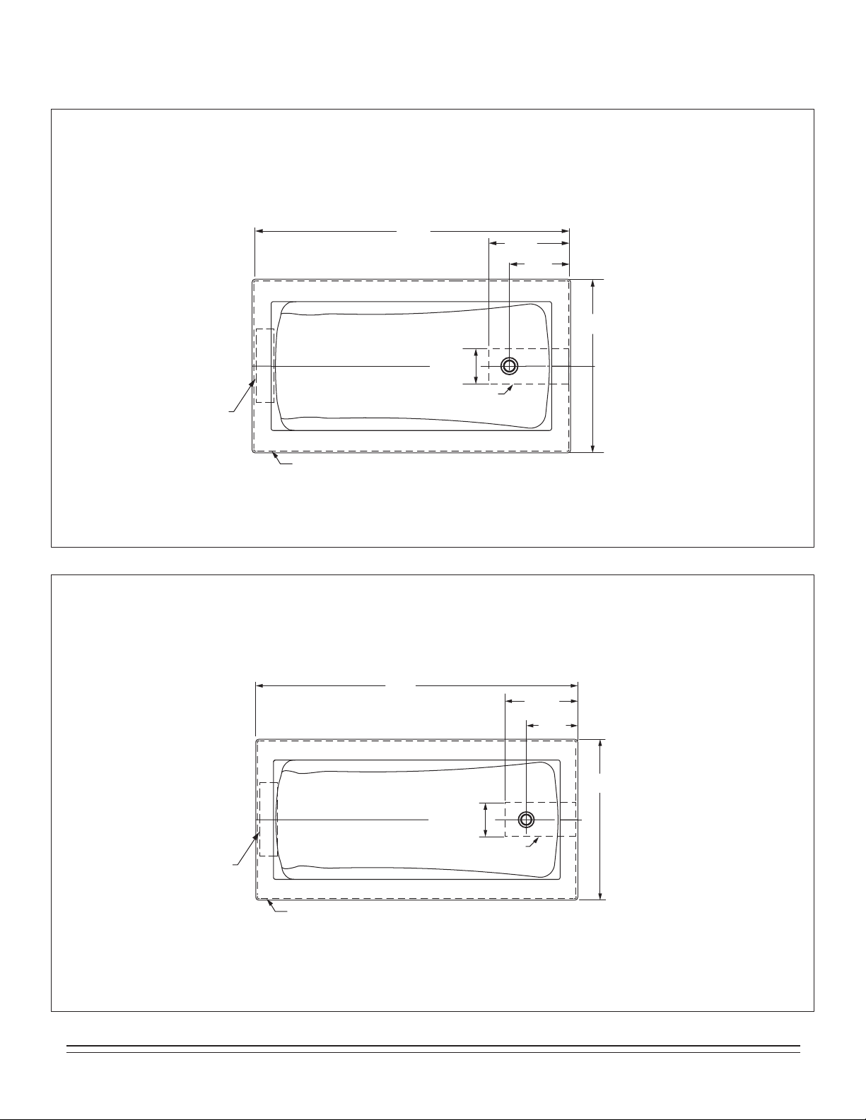
ROUGH-IN REFERENCES
MODEL SERIES 3572
66"
(1676mm)
11-1/2"
(292mm)
14-3/4"
(375mm)
36"
(914mm)
C
L
CUTOUT IN FLOOR FOR DRAIN
9"
(229mm)
OUTLINE OF CUTOUT 64.5" x 34.5" (1638 x 876mm)
PROVIDE ACCESS
TO PUMP
SERVING ON
ALL INSTALLATIONS
MODEL SERIES 3573
72"
(1829mm)
36"
(914mm)
11-1/2"
(292mm)
OUTLINE OF CUTOUT 70.5" x 34.5" (1780 x 876mm)
14-3/4"
(375mm)
9"
(229mm)
PROVIDE ACCESS
TO PUMP
SERVING ON
ALL INSTALLATIONS
C
L
CUTOUT IN FLOOR FOR DRAIN
16
754532-100 Rev. 3 3/19
ROUGH-IN REFERENCES
MODEL SERIES 3574
60"
(1524mm)
42"
(1067mm)
11-1/2"
(292mm)
OUTLINE OF CUTOUT 58.5" x 40.5" (1486 x 1029mm)
14-3/4"
(375mm)
9"
(229mm)
PROVIDE ACCESS
TO PUMP
SERVING ON
ALL INSTALLATIONS
CUTOUT IN FLOOR FOR DRAIN
C
L
MODEL SERIES 3575
72"
(1829mm)
42"
(1067mm)
11-1/2"
(292mm)
OUTLINE OF CUTOUT 70.5" x 40.5" (1780 x 1029mm)
14-3/4"
(375mm)
C
L
9"
(229mm)
CUTOUT IN FLOOR FOR DRAIN
PROVIDE ACCESS
TO PUMP
SERVING ON
ALL INSTALLATIONS
754532-100 Rev. 3 3/19
17
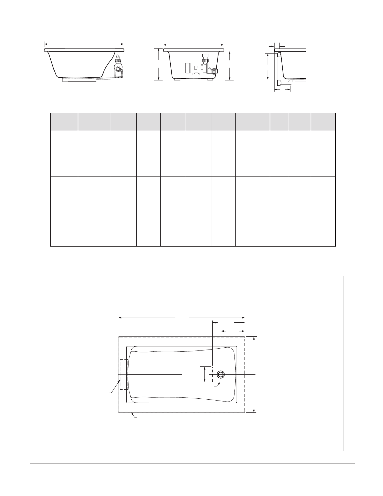
GENERAL SPECIFICATIONS FOR SERIN WHIRLPOOLS AND BATH TUBS
A 16-3/4"
(425mm)
B 10-1/4"
(260mm)
C 20"
(508mm)
4-1/8"
(105mm)
58-1/2"
(1486mm)
x 30-1/2"
(775mm)
60-3/16"
(1529mm)
x 30-1/2"
(775mm)
L 60" (1524mm)
W 32" (813mm)
H 23" (584mm)
85 lb.
(37 kg.)
536 lb. (244 kg)/
40 lb./sq.ft.
(193 kg/sq.m)
54 gal.
(204 l.)
49 gal.
(186 l.)
3581
Serin
5' x 32"
TABLE 7
MODEL SERIES 3581
30"
(762mm)
60"
(1524mm)
9-3/4"
(248mm)
9" x 12" (227 x 305mm)
CUTOUT IN FLOOR
FOR DRAIN
OUTLINE OF CUTOUT
OVERFLOW
4-1/8"
(105mm)
INTEGRAL
FITTING DECK
32"
(813mm)
PROVIDE ACCESS
TO PUMP
SERVING ON
ALL INSTALLATIONS
ROUGH-IN REFERENCES
SPECIFICATIONS:
SIDE VIEW
DRAIN / OVERF
LOW
END VIEW
L
H
W
C
A
B
J
Description
Drain /
Overflow
Cut Out
Pier
G x F
Rough-In
Recess
E x D
Tub Edge to
Centerline
Overflow: J
Weight with
Water / Floor
Loading
Product
Weight
Gallon to
Overflow
Whirlpool
Operating
Volume
Height to
Underside of
Deck Edge: C
Dimensions
L-W-H
C
L
18
754532-100 Rev. 3 3/19
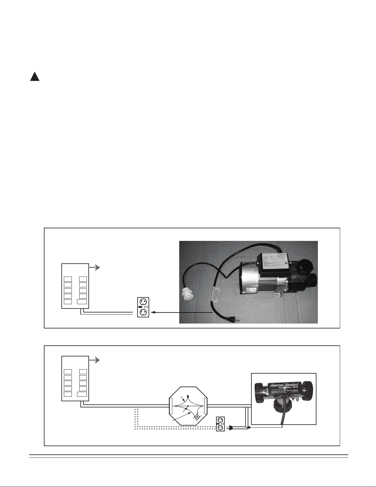
All wiring must be performed by a licensed electrician in accordance with the national electrical code and all other applicable codes.
WARNING: When using electrical products, basic precautions should always be observed, including the following:
1. DANGER: RISK OF ELECTRIC SHOCK! Connect only to a circuit protected by a ground-fault circuit interrupter.
2. Grounding is required. The unit should be installed by a licensed electrician and grounded.
3. Permit access for servicing motor as noted.
4. All building materials and wiring should be routed away from the pump body and heater (if equipped).
ELECTRICAL INSTALLATION INSTRUCTIONS
!
ELECTRICAL
FEED
GFCI
120V, 60HZ
15A GFCI
120V, 60HZ
15A GFCI
JUNCTION BOX (CANADA)
GFCI OUTLET (USA)
ELECTRICAL
FEED
AIR SWITCH ACTIVATED WHIRLPOOL PUMP
GFCI
Green/Copper
Black
White
Refer to the schematics below for the appropriate bath electrical installation. Dedicated15A circuits with GFCI (Ground
Fault Circuit Interrupter) protection are required.
At initial start-up with the power ON, push the GFCI test button. The reset button should pop out. Push this button in to
reset. If the GFCI fails to operate in this manner, there is a ground fault or malfunction, indicating the possibility of
electrical shock. Turn of the power and do not use until the source of the problem has been identifed and corrected.
754532-100 Rev. 3 3/19
19
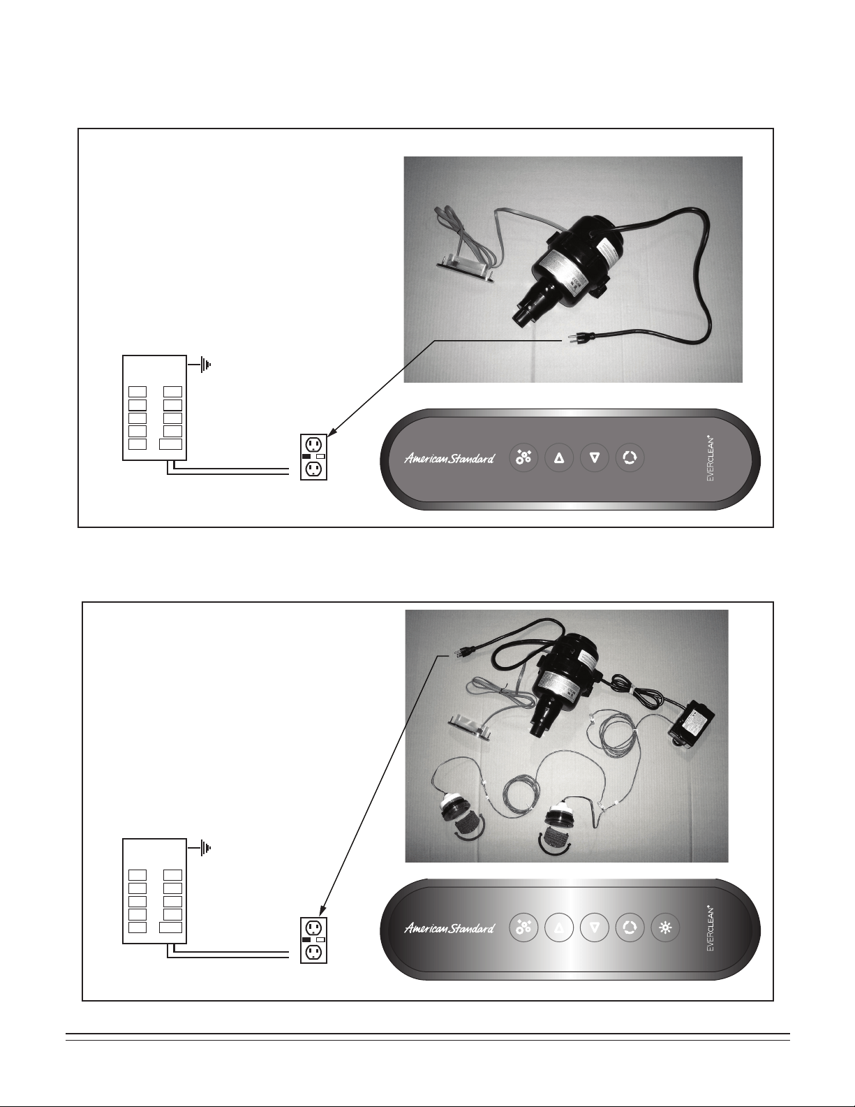
ELECTRICAL INSTALLATION INSTRUCTIONS (continued)
ELECTRONIC ACTIVATED AIR BATH (4 BUTTON PANEL)
120V, 60HZ
15A GFCI
ELECTRICAL
FEED
GFCI
ELECTRONIC ACTIVATED AIR BATH WITH LIGHTS (5 BUTTON PANEL)
120V, 60HZ
15A GFCI
ELECTRICAL
FEED
GFCI
20
754532-100 Rev. 3 3/19
ELECTRICAL INSTALLATION INSTRUCTIONS (continued)
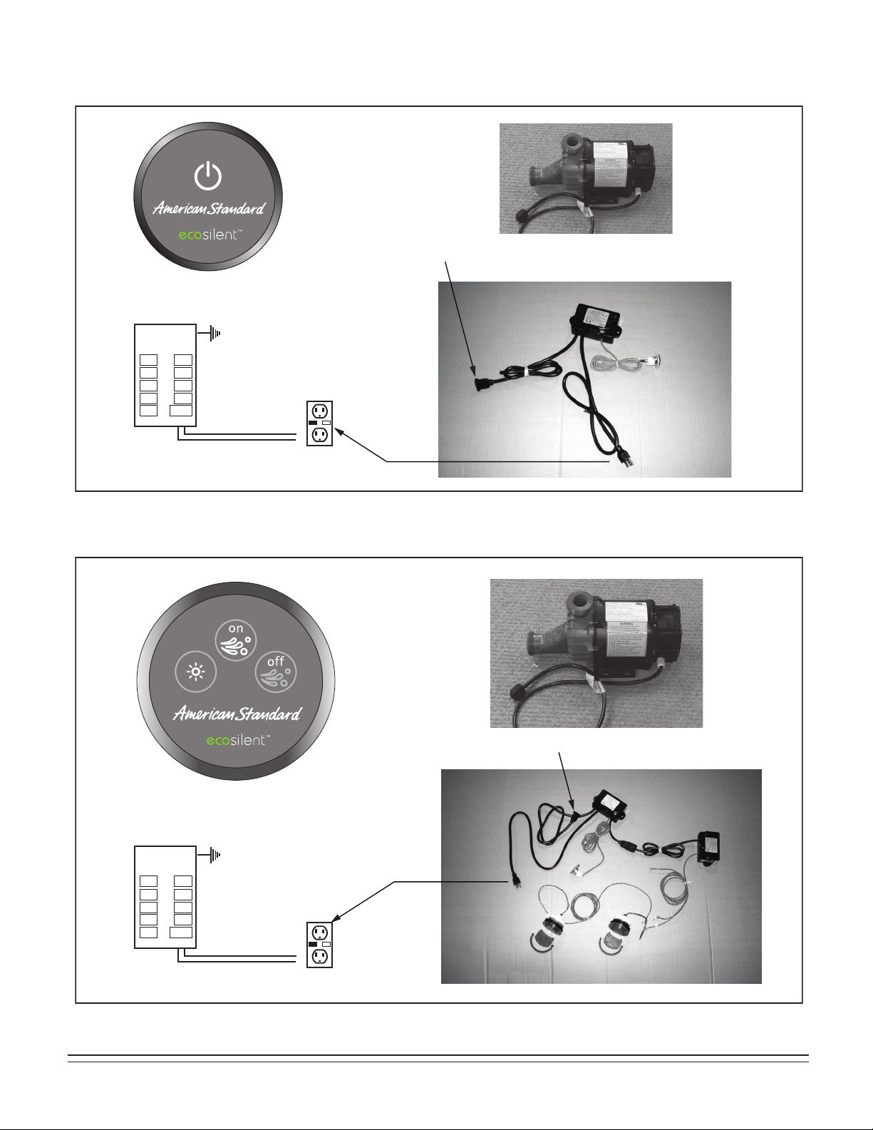
ELECTRONIC ACTIVATED ECOSILENT WHIRLPOOL (1 BUTTON PANEL)
120V, 60HZ
15A GFCI
ELECTRICAL
FEED
GFCI
ELECTRONIC ACTIVATED ECOSILENT WHIRLPOOL WITH LIGHTS (3 BUTTON PANEL)
ECOSILENT PUMP HAS P3JJ PLUG
ECOSILENT PUMP HAS P3JJ PLUG
120V, 60HZ
15A GFCI
ELECTRICAL
FEED
GFCI
ELECTRICAL INSTALLATION INSTRUCTIONS (continued)
754532-100 Rev. 3 3/19
21
ELECTRICAL INSTALLATION INSTRUCTIONS (continued)
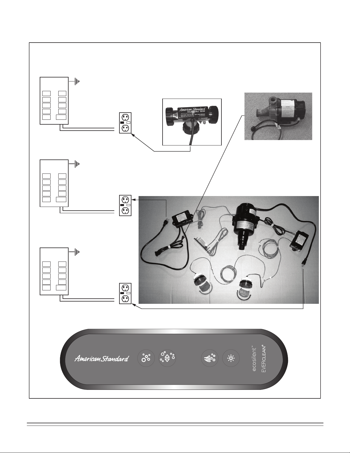
ELECTRONIC ACTIVATED COMBINATION TUB WITH LIGHTS (4 BUTTON PANEL)
120V, 60HZ
15A GFCI
(FOR HEATER)
ELECTRICAL
FEED
GFCI
120V, 60HZ
15A GFCI
ELECTRICAL
FEED
GFCI
120V, 60HZ
15A GFCI
ELECTRICAL
FEED
GFCI
ELECTRICAL INSTALLATION INSTRUCTIONS (continued)
USE THREE GFCI OUTLETS (USA MARKET)
ECOSILENT PUMP
HAS P3JJ PLUG
WHIRLPOOL HEATER IS
FACTORY INSTALLED ON
COMBINATION TUBS
22
754532-100 Rev. 3 3/19
ELECTRICAL INSTALLATION INSTRUCTIONS (continued)
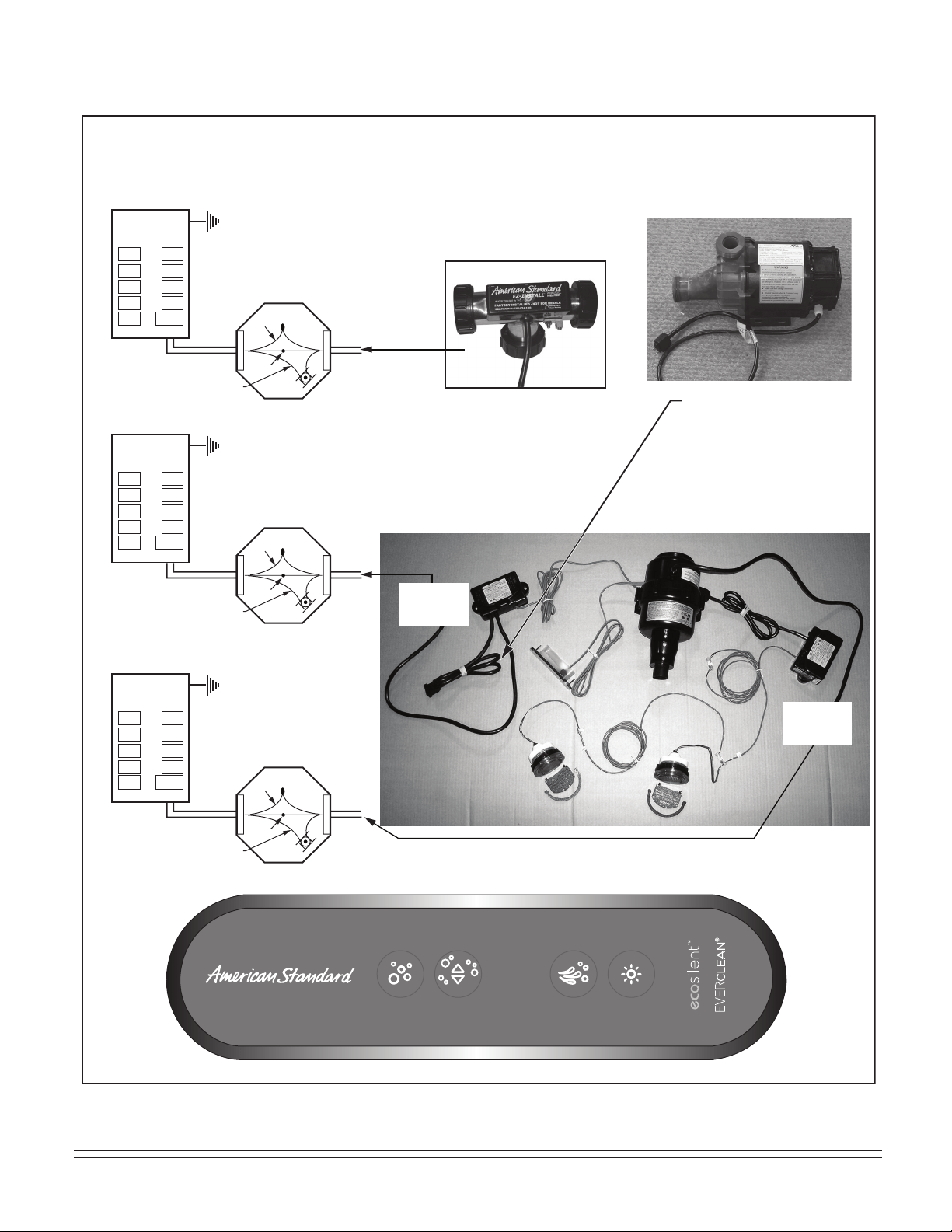
ELECTRONIC ACTIVATED COMBINATION TUB WITH LIGHTS (4 BUTTON PANEL)
120V, 60HZ
15A GFCI
(FOR HEATER)
ELECTRICAL
FEED
GFCI
120V, 60HZ
15A GFCI
ELECTRICAL
FEED
GFCI
120V, 60HZ
15A GFCI
ELECTRICAL
FEED
GFCI
ELECTRICAL INSTALLATION INSTRUCTIONS (continued)
USE THREE JUNCTION BOXES
(CANADA MARKET)
ECOSILENT PUMP
HAS P3JJ PLUG
WHIRLPOOL HEATER IS
FACTORY INSTALLED ON
COMBINATION TUBS
Green/Copper
Black
White
Green/Copper
Black
White
Green/Copper
Black
White
TO
BOX
TO
BOX
754532-100 Rev. 3 3/19
23
ELECTRICAL INSTALLATION INSTRUCTIONS
(continued)
WHIRLPOOL HEATER OPERATION
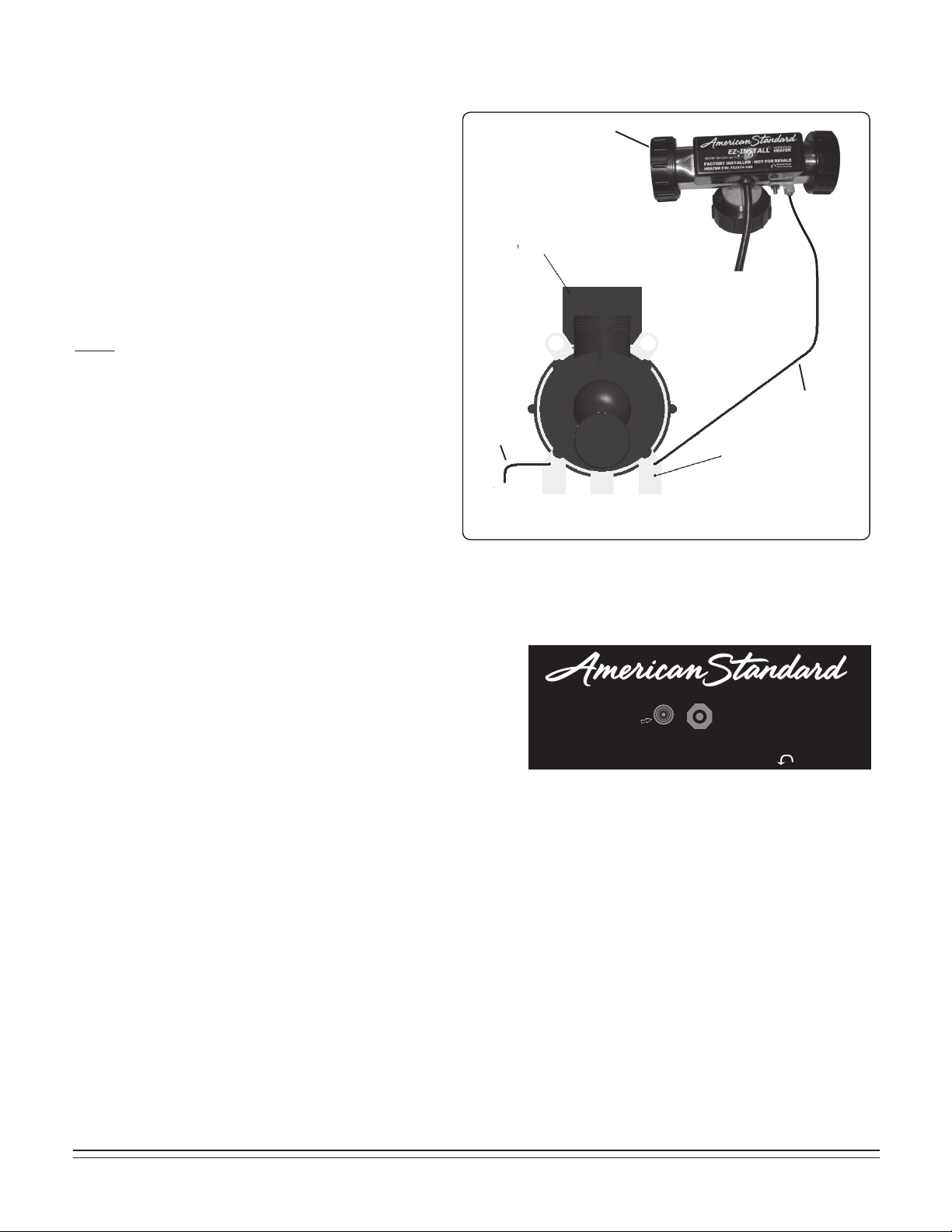
Ensure the heater and pump are properly GROUNDED
and BONDED as required. Attach the 8 AWG solid
copper conductor supplied with the heater from the
heater bonding lug to the motor frame bonding lug as
shown in Figure 3.
The conductor is secured to the lugs using set screws.
The motor frame shall have a second 8 AWG solid
copper conductor connected from the frame bonding
lug to the home’s electrical panel or approved local
bonding point as shown in Figure 3.
NOTE: For all “EcoSilent” pump configurations, the
pump housing is plastic. Therefore, the first copper
conductor attached to the heater must be grounded
directly to the home’s electrical panel or approved local
bonding point. this type of configuration does not need
the second copper conductor shown in Figure 3.
RUN 8 AWG SOLID COPPER
CONDUCTORS FROM
HEATER BONDING LUG TO
PUMP/MOTOR FRAME LUG
AND FROM PUMP/MOTOR
LUG TO APPROVED
GROUND AS SHOWN
(PUMP/MOTOR)
TO GROUND
SECOND
COPPER
CONDUCTOR
FIRST COPPER
CONDUCTOR
PUMP/MOTOR FRAME WITH
BONDING LUGS
(NOT ON “ECOSILENT” MODELS)
HEATER ON
(HEATER)
FIGURE 3: GROUNDING DIAGRAM
FIGURE 4: WHIRLPOOL HEATER
INDICATOR LIGHT
WARNING: Prior to operation, review the Important Safety
Instructions listed at the beginning of this instruction manual.
Once the heater is installed and the whirlpool pump is operating,
the heater is totally automatic. The heater will help maintain the
temperature of the water in the bath.
Pressure Switch
The heater is equipped with a preset pressure switch. The pump
must be running with water flowing in the whirlpool to allow the
heater to turn on.
Indicator Light
This light turns on whenever the heater is operating.
High-Limit Switch
The heater includes an exclusive “Intelligent High-Limit”. This safety circuit will not “false trip” from hot tap water. It
will only turn the heater off if the thermostat fails. If the high-limit trips frequently, call a service technician.
To manually reset the circuit in the event that the “High-Limit” switch has been activated, simply
(1) Tu rn off the whirlpool pump.
(2) Drain water from the tub.
(3) Remove power from heater by unplugging at receptacle or turning off circuit breaker.
(4) The heater circuit will automatically reset in less than 15 minutes.
(5) Restore power to the heater.
(6) Whirlpool bath is now ready to use.
HEATER “ON” LIGHT
Bonding Lug on
Heater Housing
E-Z INSTALL
™
WHIRLPOOL
HEATER
FACTORY INSTALLED - NOT FOR RESALE
HEATER P/N: 753174-100
24
754532-100 Rev. 3 3/19
REMOTE BLOWER LOCATION OPTION
IMPORTANT! It is not necessary that the blower motor be relocated. This option is provided for the case that a particular
installation makes this effort practical.
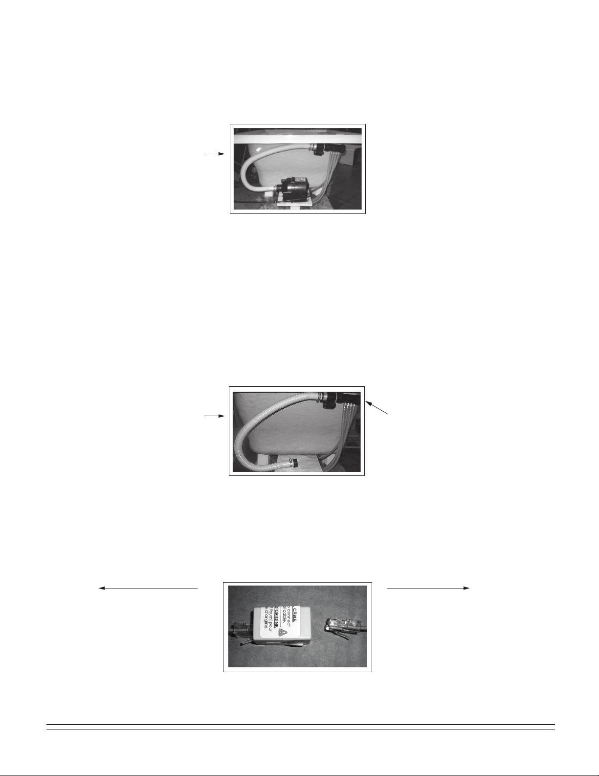
NOTE: Relocating blower motor from factory installed location, see photo 1, will require disassembly of air blower from mounting
board. Keep all hardware for reattachment at new location. Additional hardware will be required depending upon final
desired position of air blower. Follow all instructions listed below.
NOTE: Installing the blower in a remote location will reduce the system efficiency.
NOTE: Relocating a blower motor still requires a service access for the blower.
NOTE: All materials needed for the relocation must be supplied by the installer. This includes ordering a longer control panel
cable (754025-0073A), a longer flexible blower hose (753960-2030A), and up to two lighting cable extensions for combo
models (754512-0070A).
A separate circuit, which must be protected by the Ground Fault Circuit Interrupter (GFCI), is required in the remote location.
Electrical connections should be performed by a licensed electrician.
The blower motor must be located within 12 feet of rigid piping from the bath air manifold. This limitation is for the total pipe length
and applies to any direction changes and elbows. There can be no more than six changes of direction. There should be as few
direction changes as possible and the piping installation must meet all requirements of local plumbing and building codes.
Disconnect the blower from the flexible hose as shown in photo 2. Do NOT remove the check valve manifold that is mounted to the
underside of the air bath. The manifold MUST remain mounted above the tub overflow level as shown in 2.
Replace the flexible hose shown in photo 2 with the longer flexible hose (P/N 753960-2030A) using the existing hope clamps.
NOTE: Do NOT remove the original cable coming out of the blower. Instead, plug the longer cable (P/N 754025-0073A) into the
existing cable that is coming out of the blower as shown in photo 3. Then plug the remaining end of the longer cable into
the control panel which remains on the tub wall.
1.
2.
3.
TYPICAL VIEW
TYPICAL VIEW
Do NOT move check
valve manifold
TO CONTROL PANEL
754025-0073A CABLE
(INCLUDES ADAPTER
BOX SHOWN)
TO BLOWER
EXISTING
CABLE
754532-100 Rev. 3 3/19
25
REMOTE BLOWER LOCATION OPTION (continued)
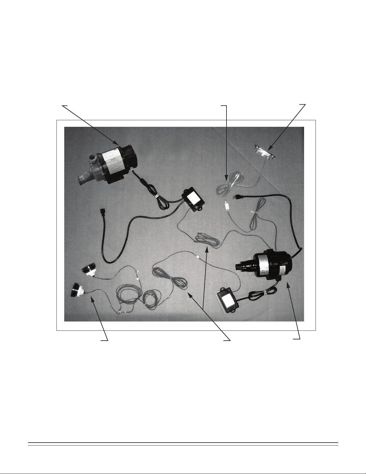
FOR THE COMBINATION WHIRLPOOL / AIR BATH CONFIGURATIONS ONLY:
Up to two additional control box extensions (P/N 754512-0070A) are required as shown in photo 4 (below). Simply extend the
cables going to the blower by adding in the extension cables. Be careful not to damage the cable connections and never plug in
cables while power is applied to blower and/or pump.
4.
LONGER CONTROL PANEL CABLE
(754025-0073A)
CONTROL PANEL
BLOWER
LIGHTS CONTROL BOX EXTENSIONS
(754512-0070A)
PUMP
26
754532-100 Rev. 3 3/19
Operation: Single Speed Whirlpool
BATHING:
• Fill bath with water at a comfortable bathing temperature - If your whirlpool is equipped with the
optional EZ-Heater, it will automatically maintain the water temperature.
• IMPORTANT: Do NOT fill the whirlpool more than 2/3 full before getting in, as it may overflow.
• IMPORTANT: Do NOT add bath oils or salts – this will damage the whirlpool pump.
• IMPORTANT: Water level must be at least one inch (25mm) above the highest jet before the whirlpool is started.
Operating the system without water (dry running) for extended periods will cause pump damage and void the warranty.
• IMPORTANT: The EcoSilent whirlpool will NOT operate unless the water level is at least one inch above
the highest jet.
STARTING WHIRLPOOL:
• Press on/off button to start whirlpool.
STOPPING WHIRLPOOL:
• Press on/off button again to stop whirlpool.
AIR VOLUME CONTROL ADJUSTMENTS:
• Water turbulence is determined by the amount of air mixed with the water. Rotate the air volume control
counterclockwise for more turbulence, and clockwise for less.
FLOW JET VOLUME ADJUSTMENTS:
• Water flow-levels can be adjusted from vigorous to soft by rotating the nozzle counterclockwise for vigorous and
clockwise for soft.
• The water flow to the mini-jets in the lumbar area of bath (if so equipped) can be adjusted by turning the mini-jet
flow control valve open (counterclockwise) or closed (clockwise). the mini-jets themselves are NOT adjustable.
AIR SWITCH ELECTRONIC SWITCH
754532-100 Rev. 3 3/19
27
BATHING:
• Fill bath with water at a comfortable bathing temperature - If your whirlpool is equipped with the optional EZ-Heater,
it will automatically maintain the water temperature.
• IMPORTANT: Do NOT fill the whirlpool more than 2/3 full before getting in, as it may overflow.
• IMPORTANT: Do NOT add bath oils or salts – this will damage the whirlpool pump.
• IMPORTANT: Water level must be at least one inch (25mm) above the highest jet before the whirlpool is started.
Operating the system without water (dry running) for extended periods will cause pump damage and void the warranty.
• IMPORTANT: The EcoSilent whirlpool will NOT operate unless the water level is at least one inch above
the highest jet.
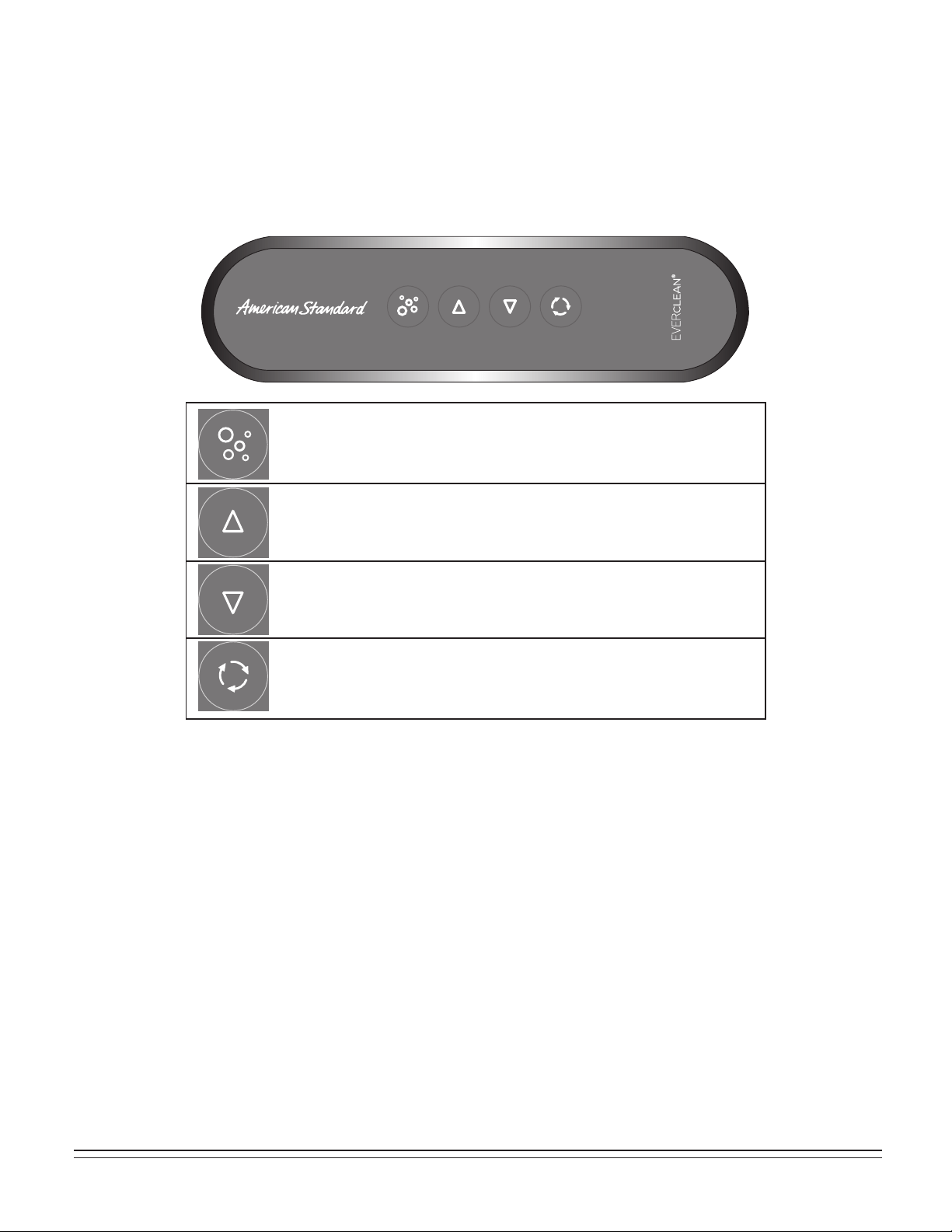
Operation: EcoSilent Whirlpool with Lights
AIR VOLUME CONTROL ADJUSTMENTS:
• Water turbulence is determined by the amount of air mixed with the water. Rotate the air volume control
counterclockwise for more turbulence, and clockwise for less.
FLOW JET VOLUME ADJUSTMENTS:
• Water flow-levels can be adjusted from vigorous to soft by rotating the nozzle counterclockwise for vigorous and
clockwise for soft.
• The water flow to the mini-jets in the lumbar area of bath (if so equipped) can be adjusted by turning the mini-jet
flow control valve open (counterclockwise) or closed (clockwise). the mini-jets themselves are NOT adjustable.
DISPLAY COLORS
1
ST
2
ND
3
TH
4
TH
5
TH
6
TH
7
TH
8
TH
9
TH
10
TH
11
TH
WHITE
SLOW RAINBOW CYCLE
FAST RAINBOW CYCLE
TURQUOISE
BLUE
MAGENTA
RED
ORANGE
YELLOW
GREEN
RETURN TO SLOW RAINBOW CYCLE
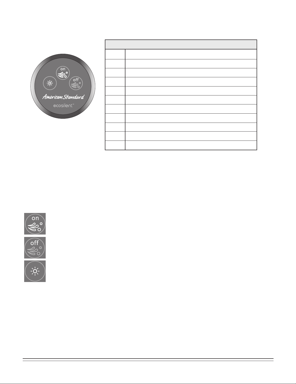
3-BUTTON ELECTRONIC SWITCH
• To start whirlpool pump, press “on” button.
• To stop whirlpool pump, press “off” button.
• To turn on Chromatherapy lights, press light button once. The cycle will start on white.
• Turn off and on within 3 seconds; it will change to slow rainbow cycle and so on per the
display color table shown above.
28
754532-100 Rev. 3 3/19
BATHING:
• IMPORTANT: DO NOT ADD BATH OILS OR SALTS as they will damage the whirlpool pump and may
harm the acrylic surface.
• Close drain by rotating Drain Overflow Knob COUNTER-CLOCKWISE
• Fill bath with water at a comfortable bathing temperature.
EXITING THE BATH
• Be sure to turn off the air blower before draining bath.
• Open drain by rotating drain knob clockwise.
OPERATING AIR MASSAGE SYSTEM:
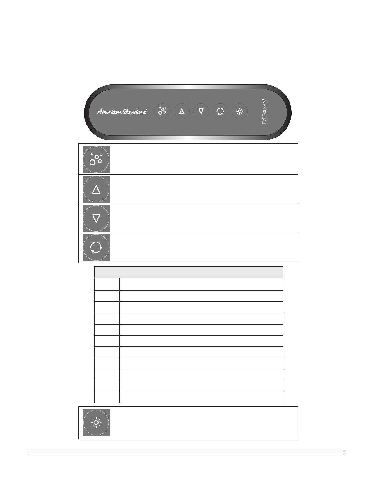
Operation: Air Bath
DRYING CYCLE OPTIONS
STANDARD DRYING CYCLE
An automatic drying cycle will start 20 minutes after the blower is turned off. The blower LED blinks while waiting for the
purge cycle.
24H PROGRAMMABLE DRYING CYCLE
The system must be stopped prior to activation or deactivation.
Activation: Determine at which time you wish to purge to activate. At that precise time, press and hold the second button on
the keypad for 5 seconds, all LEDs will flash twice. The purge cycle will now start at the programmed time every 24 hrs. In
the event of a power failure, the program will be automatically deactivated.
Deactivation: Press and hold the second button on the keypad for 5 seconds, all LEDs will flash once to confirm deactivation.
AIR SPEED INCREASE:
Pressing this button will increase to the next higher speed.
ON/OFF:
Press this button once to turn air-blower on.
Press again to turn air-blower off.
AIR SPEED DECREASE:
Pressing this button will decrease to the next lower speed.
WAVE FUNCTION:
Press this button to start the wave function (button will light).
Blower speed will continuously vary between high and low.
Press again to exit wave function (button light will go out).
754532-100 Rev. 3 3/19
29
BATHING:
• IMPORTANT: DO NOT ADD BATH OILS OR SALTS as they will damage the whirlpool pump and may
harm the acrylic surface.
• Close drain by rotating Drain Overflow Knob COUNTER-CLOCKWISE
• Fill bath with water at a comfortable bathing temperature.
OPERATING AIR MASSAGE and CHROMATHERAPY SYSTEM:
Operation: Air Bath with Lights
AIR SPEED INCREASE:
Pressing this button will increase to the next higher speed.
ON/OFF:
Press this button once to turn air-blower on.
Press again to turn air-blower off.
AIR SPEED DECREASE:
Pressing this button will decrease to the next lower speed.
WAVE FUNCTION:
Press this button to start the wave function (button will light).
Blower speed will continuously vary between high and low.
Press again to exit wave function (button light will go out).
• To turn on Chromatherapy lights, press light button once.
The cycle will start on white.
• Turn off and on within 3 seconds; it will change to slow rainbow
cycle and so on per the display color table shown above.
DISPLAY COLORS
1
ST
2
ND
3
TH
4
TH
5
TH
6
TH
7
TH
8
TH
9
TH
10
TH
11
TH
WHITE
SLOW RAINBOW CYCLE
FAST RAINBOW CYCLE
TURQUOISE
BLUE
MAGENTA
RED
ORANGE
YELLOW
GREEN
RETURN TO SLOW RAINBOW CYCLE

30
754532-100 Rev. 3 3/19
Operation: Air Bath with Lights (continued)
EXITING THE BATH
• Be sure to turn off the air blower before draining bath.
• Open drain by rotating drain knob clockwise.
DRYING CYCLE OPTIONS
STANDARD DRYING CYCLE
An automatic drying cycle will start 20 minutes after the blower is turned off. The blower LED blinks while waiting for the
purge cycle.
24H PROGRAMMABLE DRYING CYCLE
The system must be stopped prior to activation or deactivation.
Activation: Determine at which time you wish to purge to activate. At that precise time, press and hold the second button
on the keypad for 5 seconds, all LEDs will flash twice. The purge cycle will now start at the programmed time every 24
hrs. In the event of a power failure, the program will be automatically deactivated.
Deactivation: Press and hold the second button on the keypad for 5 seconds, all LEDs will flash once to confirm
deactivation.
754532-100 Rev. 3 3/19
31
BATHING:
• IMPORTANT: DO NOT ADD BATH OILS OR SALTS as they will damage the whirlpool pump and may
harm the acrylic surface.
• Close drain by rotating Drain Overflow Knob COUNTER-CLOCKWISE
• Fill bath with water at a comfortable bathing temperature
OPERATING AIR MASSAGE and CHROMATHERAPY SYSTEM:
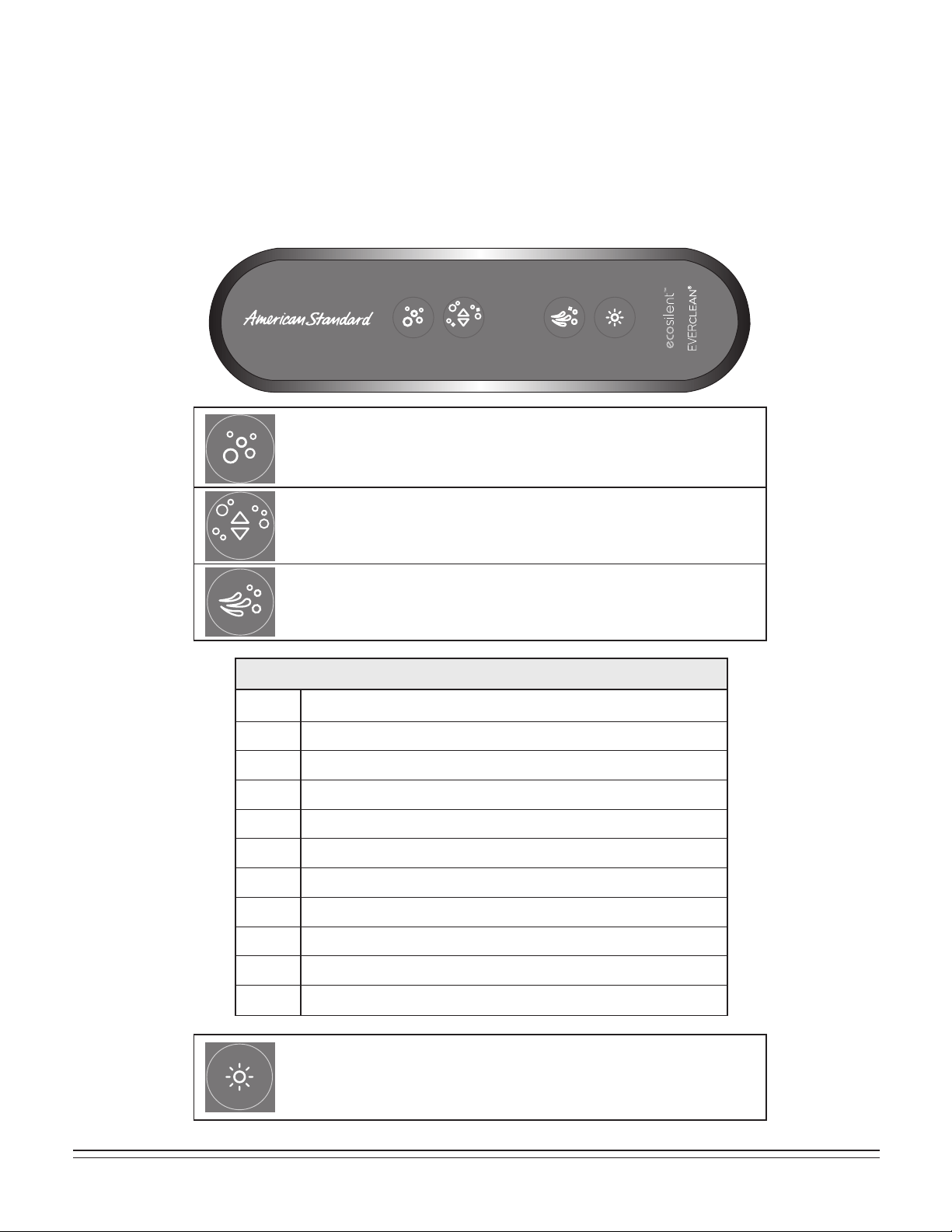
Operation: Combination Tub with Lights
• Press and hold button to increase blower speed. Release button
at desired speed.
• Press and hold button to decrease speed. Release button at
desired speed.
• Press this button to turn blower on.
• Press this button again to turn blower off.
• Press button to turn whirlpool pump on.
• Press button to turn whirlpool pump off.
• To turn on Chromatherapy lights, press light button once.
The cycle will start on white.
• Turn off and on within 3 seconds; it will change to slow rainbow
cycle and so on per the display color table shown above.
DISPLAY COLORS
1
ST
2
ND
3
TH
4
TH
5
TH
6
TH
7
TH
8
TH
9
TH
10
TH
11
TH
WHITE
SLOW RAINBOW CYCLE
FAST RAINBOW CYCLE
TURQUOISE
BLUE
MAGENTA
RED
ORANGE
YELLOW
GREEN
RETURN TO SLOW RAINBOW CYCLE

32
754532-100 Rev. 3 3/19
Operation: Combination Tub with Lights (continued)
EXITING THE BATH
• Be sure to turn off the air blower before draining bath.
• Open drain by rotating drain knob clockwise.
DRYING CYCLE OPTIONS
STANDARD DRYING CYCLE
An automatic drying cycle will start 20 minutes after the blower is turned off. The blower LED blinks while waiting for the
purge cycle.
24H PROGRAMMABLE DRYING CYCLE
The system must be stopped prior to activation or deactivation.
Activation: Determine at which time you wish to purge to activate. At that precise time, press and hold the second button
on the keypad for 5 seconds, all LEDs will flash twice. The purge cycle will now start at the programmed time every 24
hrs. In the event of a power failure, the program will be automatically deactivated.
Deactivation: Press and hold the second button on the keypad for 5 seconds, all LEDs will flash once to confirm
deactivation.

754532-100 Rev. 3 3/19
33
Fill whirlpool with warm water and add two teaspoons of powdered automatic dishwasher (not laundry)
detergent and one-half cup of household bleach to filled whirlpool.
Activate whirlpool system in accordance with operating instructions and run system for two minutes.
Drain and refill whirlpool with cold water. Circulate for five minutes.
Drain whirlpool completely after step 3 (above) is completed.
Your American Standard whirlpool is designed to give you many years of pleasure with reasonable care and maintenance.
Your new acrylic bathtub is tough, durable and easy to care for. The colors have been formulated to match other
American Standard fixtures and enhance your choice of bathroom decorations. The high gloss surface will retain its
lasting luster with proper care and maintenance.
CLEANING AND MAINTENANCE:
• Always fill the tub with temperate water. Excessively hot water (greater than 130˚ F) may cause surface damage.
• Remove bath mat after use and hang to dry. Allowing bath mat to dry in the tub may cause surface damage.
• Clean after use with a mild liquid household detergent cleaner. Do not turn on jets when such cleaners are present.
Do not use: Lestoil® Cleaner; Lysol® Disinfectant (spray or concentrate); or Lysol® Basin, Tub and Tile Cleaner;
Windex® Cleaner; Mr. Clean® Cleaner; Dow® Disinfectant Bathroom Cleaner*; or other cleaning products in
aerosol cans.
HARSH CHEMICALS, SHARP AND ABRASIVE OBJECTS
SHOULD NEVER BE USED ON ACRYLIC SURFACES
• Do not use wire brushes, knives or sharp objects to remove stains or other surface blemishes.
• Use of abrasive cleaners or powders will dull the surface. If the glossy surface looses its sheen, dulled areas can
be partially restored by rubbing with a white automotive body polishing compound and waxing with a liquid wax.
Do not wax surfaces where you walk or stand.
• Do not allow nail polish remover, acetone, dry-cleaning fluid, paint remover, or other solvents to come into contact
with the surface.
• Clean the surrounding surface immediately after using caustic drain cleaners.
Do not permit drain cleaner to enter circulation system.
• Burning cigarettes will irreparably damage the surface of the whirlpool.
CLEANING/PURGING THE CIRCULATION SYSTEM
Once every month the circulating system must be purged and cleaned. Follow the steps outlined below:
1.
2.
3.
4.
For Troubleshooting and Repair Parts please log on to www.americanstandard-us.com
* Lestoil® is a registered trademark of The Clorox Company.
Lysol® is a registered trademark of The Linden Company.
Windex® is a registered trademark of S.C. Johnson and Son, Inc.
Mr. Clean® is a registered trademark of The Proctor and Gamble Company.
Dow® is a registered trademark of The Dow Chemical Company.

34
754532-100 Rev. 3 3/19
AS America, Inc. Limited Lifetime Warranty for Premium Acrylic Air Baths
AS
America, Inc. (”American Standard”) warrants to the original consumer purchaser that it will, at its option,
r
epair or replace this whirlpool or any of its parts that are found by American Standard, in its sole judgment,
t
o be defective under normal residential use and maintenance so long as it is owned by the original
consumer pur
chaser.
This w
arranty shall only become effective upon receipt by American Standard of a completely filled out
W
arranty Registration Card evidencing proof of purchase.
This limit
ed warranty does not apply to commercial installations. The warranty for commercial installations is
thr
ee (3) years.
THIS
WARRANTY SHALL BE VOID IF THE ACCESS PANEL TO THE WHIRLPOOL IS COVERED IN ANY
MANNER CONTRAR
Y TO THE INSTALLATION INSTRUCTIONS. In no event will American Standard be
liab
le for the cost of repair or replacement of any installation materials including but not limited to tiles,
marb
le etc.
This limit
ed warranty DOES NOT COVER the following:
1.
Defects or damages arising from shipping, installation, alterations, accidents, abuse, misuse, lack of
pr
oper maintenance and cleaning as directed in the owner’s manual and use of other than genuine
American Standard replacement parts, in all cases whether caused by a plumbing contractor, service
compan
y, the owner or any other person.
2.
Deterioration through normal wear and tear and the expense of normal maintenance.
3.
Commercial application.
4.
Options and accessories. American Standard’s limited warranty on these items is one year for parts only
and e
xcludes labor. This one year limited warranty covers accessories manufactured by American
Standar
d (e.g. aprons, drains, grab bars, heaters, trim kits) against defects of material or workmanship.
Warranty coverage begins on the date the accessory was originally purchased by the owner.
5.
Postage or shipping costs for returning products for repairs or replacement under this limited warranty and
labor or other costs incurr
ed in connection with product removal or installation under this limited warranty.
6.
ANY LIABILITY FOR CONSEQUENTIAL OR INCIDENTAL DAMAGES, ALL OF WHICH ARE HEREBY
EXPRESSL
Y DISCLAIMED, OR THE EXTENSION BEYOND THE DURATION OF THIS LIMITED
WARRANTY OF ANY IMPLIED WARRANTIES, INCLUDING THOSE OF MERCHANTABILITY OR
FI
TNESS FOR AN INTENDED PURPOSE. (Some jurisdictions do not allow limitations on how long an
implied w
arranty lasts, or the exclusion or limitation of incidental or consequential damages, so these
limitations and e
xclusions may not apply to you.)
7.
Responsibility for compliance with local code requirements. (Since local code requirements vary greatly
distr
ibutors, retailers, dealers, installation contractors and users of plumbing products should determine
whether ther
e are any code restrictions on the installation or use of a specific product.)
This w
arranty gives you specific legal rights. You may have other legal rights that vary from state to state.
F
or service under this warranty, you should contact the following:
In the United States:
American Standard Brands
1 Centennial Ave
Piscataway, New Jersey 08854
Attention: Director of Customer Care
For residents of the United States, warranty
information may also be obtained by calling
the f
ollowing toll free number: (800) 442-1902
www.americanstandard.com
In Canada:
LIXIL Canada, ULC
5900 Avebury Rd.
Mississauga, Ontario
Canada L5R 3M3
Toll Free: (800) 387-0369
www.americanstandard.ca
In Mexico:
American Standard B&K Mexico
S. de R.L. de C.V.
Via Morelos #330
Col. Santa Clara
Ecatepec 55540 Edo. Mexico
Toll Free: 01-800-839-1200
www.americanstandard.com.mx