
perator's
I:RnFrSMRN°
LAWN TRACTOR
22 HP, Hydrostatic Drive
46" Deck
Model No. 247.289150
• Espanol, P. 60
This product has a low emission engine which operates differently
from previously built engines. Before you start the engine, read and
understand this Operator's Manual.
Before using this equipment,
read this manual and follow
all safety rules and operating
instructions.
For answers to your questions about
this product, call:
1-800=659=5917
Craftsman Tractor Help Line
7 am = 7 pm CT, Mort. =Sun.
Sears Brands Management Corporation, Hoffman Estates, IL 60179 U.S.A.
Visit our website: www.craftsman.com FormNo.769-08541
(November1,2012)
Warranty Statement .......................................................... 2
Safety Instructions ............................................................ 3
Slope Gauge ..................................................................... 8
Assembly ........................................................................... 9
Operation ........................................................................ 11
Service and Maintenance .............................................. 17
Off-Season Storage ........................................................ 27
Trou bleshooting .............................................................. 28
Labels ............................................................................. 29
Parts List ......................................................................... 30
Espafiol ............................................................................ 60
Service Numbers ............................................. Back Cover
CRAFTSMAN FULL WARRANTY
FORTWOYEARSfromthedate of purchase,all non-expendablepartsof this ridingequipmentare warrantedagainstany defectsin materialor
workmanship.A defectivenon-expendablepart will receivefree in-homerepairor replacementif repairis unavailable.
BATTERYLIMITEDWARRANTY
FOR90 DAYSfromthe dateof purchase,the battery(an expendablepart)of this ridingequipmentis warrantedagainstanydefectsin materialor
workmanship.A newbatterywill be suppliedfree of charge.Youareresponsibleforthe laborcostof batteryinstallation.
ADDITIONALLIMITEDWARRANTIES
inthe followingadditionalwarranties,you areresponsibleforthe laborcost of partinstallationafterthe secondyearfromthe dateof purchase.
FORFiVEYEARSfromthedate of purchase,the frameof this ridingequipmentis warrantedagainstany defectsinmaterialor workmanship.A
newframewill be suppfiedfreeof charge.
FORTENYEARSfrom the dateof purchase,the frontaxle of thisridingequipmentis warrantedagainstany defectsin materialor workmanship.
A newfrontaxle will be suppliedfreeof charge.
FORASLONGASIT iSUSEDby theoriginalownerafterthetenthyearfromthedateof purchase,thecastironfrontaxle(if equipped)ofthisriding
equipmentiswarrantedagainstanydefectsin materialorworkmanship.Withproofofpurchase,a newcastironfrontaxlewillbesuppliedfreeofcharge.
WARRANTYSERVICE
Forwarrantycoveragedetailsto obtainfreerepairor replacement,carl1-800-659-5917orvisit the website: www.craftsman.com
inallcasesabove,if part repairor replacementis impossible,the ridingequipmentwill be replacedfree of chargewiththe sameor anequivalent
model.
Allof the abovewarrantycoverageis void if thisridingequipmentis everusedwhileprovidingcommercialservicesor if rentedto anotherperson.
ThiswarrantycoversONLYdefectsin materialand workmanship.Warrantycoveragedoes NOTinclude:
• Expendableparts(exceptbattery)thatcanwearout fromnormalusewithinthe warrantyperiod,includingbut notlimitedto blades,spark
plugs,air cleaners,belts,andoil filters.
Standardmaintenanceservicing,oil changes,or tune-ups.
Tire replacementor repaircausedby puncturesfrom outsideobjects,such as nails,thorns,stumps,or glass.
• Tireor wheelreplacementor repairresultingfromnormalwear,accident,or improperoperationor maintenance.
Repairsnecessarybecauseof operatorabuse,includingbut notlimitedto damagecausedby towingobjectsbeyondthe capabilityof the
ridingequipment,impactingobjectsthatbend theframe,axle assemblyor crankshaft,or over-speedingthe engine.
• Repairsnecessarybecauseof operatornegligence,includingbut not limitedto,electricaland mechanicaldamagecausedby improper
storage,failureto usethe propergradeandamountof engineoil, failureto keepthe deckclearof flammabledebris,orfailureto maintainthe
ridingequipmentaccordingto the instructionscontainedin theoperator'smanual.
• Engine(fuelsystem)cleaningor repairscausedbyfuel determinedto becontaminatedoroxidized(stale).in general,fuel shouldbeused
within30 daysof itspurchasedate.
• Normaldeteriorationandwearof the exteriorfinishes,or productlabelreplacement.
Thiswarrantygivesyou specificlegalrights,andyou mayalso haveotherrightswhichvaryfromstateto state.
Sears Brands ManagementCorporation, Hoffman Estates, iL60179
Model Number:
EngineOil: SAE30 Serial Number:
Fuel: UnleadedGasoline Dateof Purchase:
Engine: KohlerCourageSV620-3215 Recordthe modelnumber,serialnumber,
anddateof purchaseabove,
© SearsBrands,LLC 2
Thissymbolpointsout importantsafetyinstructionswhich,if not
followed,couldendangerthepersonalsafetyand/orpropertyof
yourselfand others. Readand followall instructionsin this manual
beforeattemptingto operatethis machine.Failureto complywith
theseinstructionsmayresultin personalinjury.Whenyou seethis
symbol,HEEDITSWARNING!
CALIFORNIA PROPOSITION 65
EngineExhaust,someof itsconstituents,andcertainvehicle
componentscontainoremit chemicalsknownto Stateof California
to cause cancerand birthdefects or other reproductiveharm.
Batteryposts,terminals,and relatedaccessoriescontainleadand
leadcompounds,chemicalsknownto the Stateof Californiato
causecancerand reproductiveharm.Washhandsafterhandling.
Thismachinewasbuiltto be operatedaccordingto the safeopera-
tion practicesin this manual.As withanytypeof powerequipment,
carelessnessorerroron the partof the operatorcan resultin serious
injury.Thismachineis capableof amputatingfingers,hands,toes
andfeet and throwingdebris.Failureto observethe followingsafety
instructionscouldresultin seriousinjuryor death.
Your Responsibility--Restrictthe use of thispowermachineto
personswho read,understandand follow thewarningsand instruc-
tionsin this manualandon the machine.
SAVE THESE INSTRUCTIONS!
GENERAL OPERATION
• Read,understand,andfollowall instructionson the machineand
in themanual(s)beforeattemptingto assembleand operate.
Keepthis manualin a safe placefor futureand regularreference
andfor orderingreplacementparts.
• Befamiliarwithall controlsand their properoperation.Knowhow
to stop the machineanddisengagethemquickly.
• Neverallowchildrenunder14yearsold to operatethis machine.
Children14 yearsold and over shouldreadandunderstandthe
operationinstructionsand safety rulesinthis manualandshould
betrainedandsupervisedbya parent.
• Neverallowadultsto operatethis machinewithoutproper
instruction.
• Tohelp avoidbladecontactor a thrownobjectinjury, keep
bystanders,helpers,childrenand pets at least75 feet fromthe
machinewhile it is in operation.Stopmachineif anyoneenters
the area.
• Thoroughlyinspectthe areawherethe equipmentis to be used.
Removeall stones,sticks,wire, bones,toys,andotherforeign
objectswhich couldbe pickedup and thrownby the blade(s).
Thrownobjectscan causeseriouspersonalinjury.
• Planyour mowingpatternto avoiddischargeof materialtoward
roads,sidewalks,bystandersandthe like.Also, avoiddischarg-
ingmaterialagainstawall orobstructionwhichmaycause
dischargedmaterialto ricochetback towardthe operator.
• Alwayswear safetyglassesor safetygogglesduring operation
andwhile performingan adjustmentor repairto protectyoureyes.
Thrownobjectswhichricochetcancauseseriousinjuryto the
eyes.
• Wearsturdy,rough-soledwork shoesand close-fittingslacksand
shirts.Loosefittingclothesandjewelrycanbe caughtin movable
parts.Neveroperatethis machinein bare feet or sandals.
• Be awareof the mowerandattachmentdischargedirectionand
do not pointit at anyone.Donot operatethe mowerwithoutthe
dischargecoverorentiregrasscatcherin its properplace.
Donot put handsor feetnear rotatingpartsor underthe cutting
deck. Contactwith the blade(s)can amputatehandsand feet.
A missingor damageddischargecovercan causeblade contact
or thrownobjectinjuries.
• Stoptheblade(s)whencrossinggraveldrives,walks,or roads
andwhile notcuttinggrass.
• Watchfor trafficwhenoperatingnearor crossingroadways.This
machineis not intendedfor useonany public roadway.
• Donot operatethe machinewhile underthe influenceof alcohol
or drugs.
• Mowonly indaylightorgoodartificiallight.
Nevercarrypassengers.
• Disengageblade(s)beforeshiftinginto reverse.Backup slowly.
Alwayslookdownandbehindbeforeandwhile backingto avoida
back-overaccident.
3
• Slowdownbeforeturning.Operatethe machinesmoothly.Avoid
erraticoperationand excessivespeed.
Disengageblade(s),setparkingbrake,stopengineand wait until
the blade(s)cometo a completestopbeforeremovinggrass
catcher,emptyinggrass,uncloggingchute,removinganygrassor
debris,or makinganyadjustments.
Neverleavea runningmachineunattended.Alwaysturnoff
blade(s),setparkingbrake,stopengineand removekey before
dismounting.
Useextracare whenloadingorunloadingthe machineintoa
trailerortruck.Thismachineshouldnot bedrivenup or down
ramp(s),becausethe machinecouldtip over,causingserious
personalinjury.The machinemustbe pushedmanuallyon
ramp(s)to loador unloadproperly.
Mufflerand engine becomehotand can causea burn.Do not
touch.
Checkoverheadclearancescarefullybeforedrivingunderlow
hangingtree branches,wires,door openingsetc.,wherethe
operatormay be struckor pulledfrom the machine,whichcould
resultinseriousinjury.
Disengageallattachmentclutchesand depressthe brakepedal
completelybeforeattemptingto start engine.
Yourmachineisdesignedto cut normalresidentialgrassof a
heightnomorethan 10".Do not attemptto mowthroughunusually
tall,dry grass (e.g.,pasture)orpiles of dry leaves.Dry grass or
leavesmaycontactthe engineexhaustand/or builduponthe
mowerdeckpresentinga potentialfire hazard.
Useonlyaccessoriesand attachmentsapprovedfor this machine
by the machinemanufacturer.Read,understandandfollowall
instructionsprovidedwith the approvedaccessoryor attachment.
Fora list of approvedaccessoriesandattachments,call 1-800-
659-5917.
Dataindicatesthatoperators,age 60 years and above,are
involvedin a largepercentageof riding mower-relatedinjuries.
Theseoperatorsshouldevaluatetheirability to operatethe riding
mowersafelyenoughto protectthemselvesandothersfrom
seriousinjury.
If situationsoccurwhicharenot coveredinthismanual,usecare
andgoodjudgment.
SLOPE OPERATION
Slopesarea majorfactorrelatedto lossof controlandtip-over
accidentswhichcan result in severeinjuryor death.All slopes require
extracaution.Ifyoucannotback up the slopeor if youfeel uneasyon
it, do not mowit.
Foryoursafety,use the SlopeGuideincludedas partof this manual
to measureslopesbeforeoperatingthis machineona slopedor hilly
area. If the slopeis greaterthan15 degreesas shownonthe Slope
Guide,do notoperatethis machineonthatareaor seriousinjurycould
result.
Do:
o
Mowupand down slopes,not across.Exerciseextremecaution
whenchangingdirectionon slopes.
• Watchfor holes,ruts,bumps,rocks,or other hiddenobjects.
Uneventerraincouldoverturnthe machine.Tallgrasscan hide
obstacles.
Useslowspeed.Choosea lowenoughspeedsettingso that
you will nothaveto stopor shiftwhileon the slope.Tiresmay
lose tractionon slopeseventhoughthe brakesare functioning
properly.Alwayskeepmachinein gearwhen goingdownslopes
to take advantageof enginebrakingaction.
• Followthe manufacturer'srecommendationsfor wheelweightsor
counterweightsto improvestability.
Useextracarewithgrasscatchersor otherattachments.These
can changethe stabilityof the machine.
Keepallmovementonthe slopesslowand gradual.Do not make
suddenchangesinspeedor direction.Rapidengagementor
brakingcouldcausethe frontof the machineto lift and rapidlyflip
overbackwardswhich couldcauseseriousinjury.
• Avoidstartingorstoppingon a slope. If tires losetraction,disen-
gagethe blade(s)and proceedslowlystraightdownthe slope.
DoNot:
• Donot turnon slopesunlessnecessary;then,turnslowlyand
graduallydownhill,if possible.
• Donot mow neardrop-offs,ditchesor embankments.The mower
could suddenlyturnover if a wheelis overthe edgeof a cliff,
ditch,or if an edgecavesin.
• Donot try to stabilizethe machineby puttingyourfooton the
ground.
• Donot usea grass catcheron steepslopes.
• Donot mowon wet grass.Reducedtractioncouldcausesliding.
• Donot attemptto coastdownhill.Over-speedingmaycausethe
operatorto lose controlof the machineresultingin seriousinjury
or death.
• Donot tow heavypull behindattachments(e.g. loadeddumpcart,
lawn roller,etc.)on slopesgreaterthan5 degrees.Whengoing
down hill,the extraweighttendsto pushthe tractorandmay
causeyou to loosecontrol(e.g.tractormayspeedup, brakingand
steeringabilityare reduced,attachmentmayjack-knifeandcause
tractorto overturn).
4
CHILDREN
Tragicaccidentscanoccurifthe operatoris notalert to the presence
of children.Childrenare often attractedto the machineand the mowing
activity.Theydo notunderstandthe dangers.Neverassumethat
childrenwill remainwhereyou lastsawthem.
• Keepchildrenout of the mowingareaand inwatchfulcare of a
responsibleadultotherthanthe operator.
• Bealert and turnmachineoff ifa childentersthe area.
• Beforeand whilebacking,lookbehindand downfor small
children.
Nevercarrychildren,evenwiththe blade(s)shutoff.Theymay
fall off and be seriouslyinjuredorinterferewithsafe machine
operation.
• Useextremecarewhenapproachingblind corners,doorways,
shrubs,trees or otherobjectsthatmay block yourvisionof a child
whomayrunintothe machine.
Toavoidback-overaccidents,alwaysdisengagethe cutting
blade(s)beforeshiftingintoReverse.If equipped,the "Reverse
CautionMode"(bladesoperatewhilemachineridesinreverse)
shouldnotbe usedwhenchildrenor othersare around.
Keepchildrenaway from hotor runningengines.They cansuffer
burnsfroma hotmuffler.
• Removekeywhenmachineisunattendedto preventunauthorized
operation.
Neverallowchildrenunder14 yearsof ageto operatethis machine.
Children14 and overshouldreadandunderstandthe instructionsand
safeoperationpracticesin thismanualand on the machineandshould
betrainedandsupervisedbyan adult.
TOWING
Towonlywitha machinethathasa hitch designedfor towing.Do
not attachtowedequipmentexceptat the hitchpoint.
Followthe manufacturersrecommendationforweightlimitsfor
towedequipmentandtowingon slopes.
Neverallowchildrenor othersinor on towedequipment.
Onslopes,theweightof thetowedequipmentmaycause lossof
tractionand loss of control.
Alwaysuseextracautionwhentowingwith a machinecapableof
makingtightturns (e.g."zero-turn"ride-onmower). Makewide
turnsto avoidjack-knifing.
Travelslowlyand allowextradistanceto stop.
Do notcoastdownhill.
SERVICE
SafeHandlingof Gasoline
Toavoidpersonalinjuryorpropertydamageuse extremecarein
handlinggasoline.Gasolineisextremelyflammableandthe vaporsare
explosive.Seriouspersonalinjurycanoccur whengasolineis spilled
on yourselfor your clotheswhich can ignite.Washyourskin and
changeclothesimmediately.
• Useonly anapprovedgasolinecontainer.
Neverfill containersinsidea vehicleor on a truckortrailer bed
witha plasticliner.Alwaysplacecontainerson the groundaway
fromyourvehiclebeforefilling.
Whenpractical,removegas-poweredequipmentfrom the truck
or trailerandrefueliton theground.If this isnot possible,then
refuelsuch equipmenton a trailerwitha portablecontainer,rather
than froma gasolinedispensernozzle.
Keepthe nozzleincontactwith the rim of the fueltank or
containeropeningat all timesuntilfuelingiscomplete.Donot use
a nozzlelock-opendevice.
Extinguishall cigarettes,cigars,pipesandothersourcesof
ignition.
• Neverfuel machineindoors.
Neverremovegascap or addfuelwhilethe engineis hotor run-
ning.Allowengineto coolat least two minutesbeforerefueling.
Neveroverfill fuel tank. Filltankto no morethan 1/2inchbelow
bottomof filler neckto allowspaceforfuel expansion.
• Replacegasolinecap and tightensecurely.
• If gasolineis spilled,wipeitoff the engineand equipment.Move
machineto anotherarea.Wait5 minutesbeforestartingthe
engine.
• To reducefire hazards,keepmachinefree of grass,leaves,or
otherdebrisbuild-up.Cleanup oil or fuel spillageandremoveany
fuel soakeddebris.
• Neverstorethe machineor fuelcontainerinsidewherethere isan
openflame,sparkor pilotlight as ona waterheater,spaceheater,
furnace,clothesdryeror othergasappliances.
Allowa machineto coolat leastfiveminutesbeforestoring.
GeneralService
• Neverrunanengineindoorsorina poorlyventilatedarea.Engine
exhaustcontainscarbonmonoxide,anodorless,anddeadlygas.
• Beforecleaning,repairing,orinspecting,makecertainthe
blade(s)andallmovingpartshavestopped.Disconnectthespark
plugwireandgroundagainsttheenginetopreventunintended
starting.
• Periodicallychecktomakesurethebladescometocomplete
stopwithinapproximately(5)fivesecondsafteroperatingthe
bladedisengagementcontrol.Ifthebladesdonotstopwithinthe
thistimeframe,yourmachineshouldbeservicedprofessionally
byaSearsorotherqualifiedservicedealer.
• Checkbrakeoperationfrequentlyasitissubjectedtowearduring
normaloperation.Adjustandserviceasrequired.
• Checktheblade(s)andenginemountingboltsatfrequent
intervalsforpropertightness.Also,visuallyinspectblade(s)
fordamage(e.g.,excessivewear,bent,cracked).Replacethe
blade(s)withtheoriginalequipmentmanufacturer's(O.E.M.)
blade(s)only,listedinthismanual.Useofpartswhichdonot
meettheoriginalequipmentspecificationsmayleadtoimproper
performanceandcompromisesafety!
• Mowerbladesaresharp.Wrapthebladeorweargloves,anduse
extracautionwhenservicingthem.
• Keepallnuts,bolts,andscrewstighttobesuretheequipmentis
insafeworkingcondition.
• Nevertamperwiththe safetyinterlocksystemor othersafety
devices.Checktheir properoperationregularly.
• Afterstrikinga foreignobject,stop the engine,disconnectthe
sparkplugwire(s)and groundagainstthe engine.Thoroughly
inspectthe machinefor anydamage.Repairthe damagebefore
startingandoperating.
• Neverattemptto makeadjustmentsor repairsto the machine
whilethe engineis running.
• Grasscatchercomponentsandthe dischargecoverare subject
to wearanddamagewhichcouldexposemovingpartsor allow
objectsto be thrown.Forsafetyprotection,frequentlycheck
componentsand replaceimmediatelywithoriginalequipment
manufacturer's(O.E.M.)partsonly,listedinthis manual.Useof
partswhichdo not meetthe originalequipmentspecificationsmay
leadto improperperformanceandcompromisesafety!
• Donot changethe enginegovernorsettingsorover-speedthe
engine.The governorcontrolsthe maximumsafe operatingspeed
of the engine.
Maintainor replacesafetyand instructionlabels,as necessary.
• Observeproperdisposallawsandregulationsfor gas,oil, etc.to
protecttheenvironment.
• Accordingto the ConsumerProductsSafetyCommission(CPSC)
andthe U.S.EnvironmentalProtectionAgency(EPA),this product
has an AverageUsefulLifeof seven(7)years,or 270hours
of operation.At the end of the AverageUsefulLife,buy anew
machineor havethe machineinspectedannuallybya Searsor
otherqualifiedservicedealerto ensurethat all mechanicaland
safetysystemsareworkingproperlyandnot wornexcessively.
Failureto doso can resultinaccidents,injuriesor death.
DO NOT MODIFY ENGINE
Toavoid seriousinjuryor death,do notmodifyengine in anyway.
Tamperingwiththe governorsettingcanleadto a runawayengineand
causeit to operateat unsafespeeds.Nevertamper with factorysetting
of enginegovernor.
NOTICE REGARDING EMISSIONS
Engineswhicharecertifiedto complywithCaliforniaandfederal
EPAemissionregulationsfor SORE(SmallOffRoadEquipment)are
certifiedto operateon regularunleadedgasoline,andmayinclude
the followingemissioncontrolsystems:EngineModification(EM)and
ThreeWayCatalyst(TWO)if so equipped.
SPARK ARRESTOR
Thismachineisequippedwithan internalcombustionengineand
shouldnot beusedonor near anyunimprovedforest-covered,
brushcoveredor grass-coveredlandunlesstheengine'sexhaust
systemis equippedwitha sparkarrestormeetingapplicablelocalor
statelaws(if any).
Ifa sparkarrestoris used,it shouldbe maintainedin effectiveworking
orderby the operator.Inthe Stateof Californiatheaboveis required
by law (Section4442of the CaliforniaPublicResourcesCode). Other
statesmayhavesimilarlaws.Federallawsapplyonfederallands.
A sparkarrestorfor the muffleris availablethroughyournearestSears
PartsandRepairServiceCenter.
6
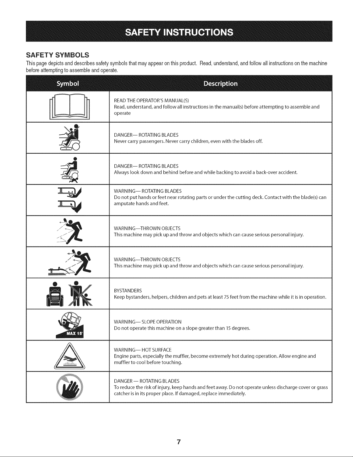
SAFETY SYMBOLS
Thispagedepictsanddescribessafety symbolsthat may appearon this product. Read,understand,andfollowallinstructionson the machine
beforeattemptingto assembleand operate.
O
A
READ THE OPERATOR'S MANUAL(S)
Read, understand, and follow all instructions in the manual(s) before attempting to assemble and
operate
DANGER-- ROTATING BLADES
Never carry passengers. Never carry children, even with the blades off.
DANGER-- ROTATING BLADES
Always look down and behind before and while backing to avoid a back-over accident.
WARNING-- ROTATING BLADES
Do not put hands or feet near rotating parts or under the cutting deck. Contact with the blade(s) can
amputate hands and feet.
WARNING--THROWN OBJECTS
This machine may pick up and throw and objects which can cause serious personal injury.
WARNING--THROWN OBJECTS
This machine may pick up and throw and objects which can cause serious personal injury.
BYSTANDERS
Keep bystanders, helpers, children and pets at least 75 feet from the machine while it is in operation.
WARNING-- SLOPE OPERATION
Do not operate this machine on a slope greater than 15 degrees.
WARNING-- HOT SURFACE
Engine parts, especially the muffler, become extremely hot during operation. Allow engine and
muffler to cool before touching.
DANGER- ROTATING BLADES
To reduce the risk of injury, keep hands and feet away. Do not operate unless discharge cover or grass
catcher is in its proper place. If damaged, replace immediately.
7
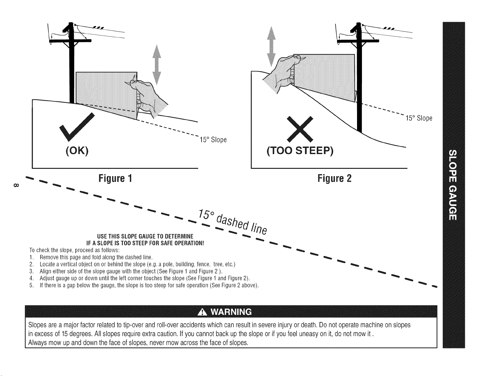
(OK)
15° Slope
X
(TOO STEEP)
15° Slope
'_. _ Figure1
USETHISSLOPEGAUGETODETERMINE
IFA SLOPEIS TOOSTEEPFORSAFEOPERATION!
To checkthe slope,proceedas follows:
1. Removethis pageandfold along the dashedline.
2. Locatea verticalobject onor behindthe slope (e.g.a pole, building,fence, tree,etc.)
3. Align eitherside of the slope gaugewith the object(SeeFigure1 and Figure2 ).
4. Adjust gaugeup or down until the left cornertouchesthe slope (SeeFigure1and Figure2).
5.
15°
dashed line
If there is agap belowthe gauge,the slope is too steepfor safeoperation(SeeFigure2 above).
Figure2
Slopes are a majorfactor related to tip-over and roll-over accidents which can result in severe injury or death. Do not operatemachine on slopes
in excess of 15 degrees. All slopes require extra caution. If you cannot back up the slope or if you feel uneasy on it, do not mow it.
Always mow up and down the face of slopes, never mow across the face of slopes.
IM PORTANT: Yourtractorisshippedwith motoroil inthe engine.However,
youMUSTchecktheoil levelbeforeoperating.Referto the Service& Maintenance
sectionforinstructionson CheckingTheEngineOil.
Attachingthe BatteryCables
California Proposition65
Batteryposts,terminals,and relatedaccessoriescontainleadand
leadcompounds,chemicalsknownto the Stateof Californiato
causecancerand reproductiveharm.Washhandsafterhandling.
ShippingBraceRemoval
Makesurethe ridingmower'sengineis off, removetheignitionkey,
andset the parkingbrakebeforeremovingthe shippingbrace. Refer
jto the Operationsectionfor instructionsonhowto setthe parking
lbrake.
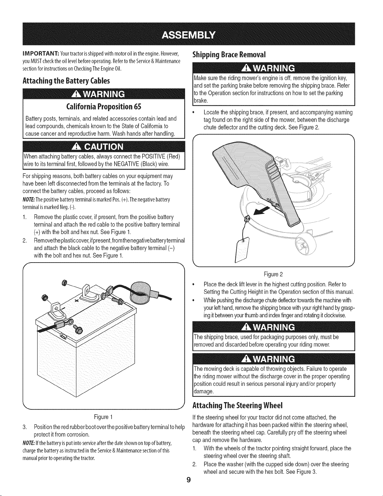
* Locatethe shippingbrace, if present,and accompanyingwarning
tag foundonthe rightsideof the mower,betweenthe discharge
chutedeflectorandthe cuttingdeck. See Figure2.
Whenattachingbatterycables,alwaysconnectthe POSITIVE(Red)
wireto its terminalfirst, followedby the NEGATIVE(Black)wire.
Forshippingreasons,bothbatterycableson yourequipmentmay
havebeenleftdisconnectedfromthe terminalsat the factory.To
connectthe batterycables,proceedasfollows:
NOTE:ThepositivebatteryterminalismarkedPos.(+).Thenegativebattery
terminalismarkedNeg.(-).
1. Removethe plasticcover,if present,fromthe positivebattery
terminaland attachthe redcableto the positivebatteryterminal
(+)withthe bolt andhexnut.See Figure1.
2. Removetheplasticcover,ifpresent,fromthenegativebatteryterminal
andattachthe blackcableto thenegativebatteryterminal(-)
withthe boltandhex nut.See Figure1.
Figure2
Placethe decklift leverinthe highestcuttingposition.Referto
SettingtheCuttingHeightin the Operationsectionof thismanual.
Whilepushingthedischargechutedeflectortowardsthemachinewith
yourlefthand,removetheshippingbracewithyourrighthandbygrasp-
ingitbetweenyourthumbandindexfingerandrotatingitclockwise.
The shippingbrace,usedfor packagingpurposesonly, mustbe
removedand discardedbeforeoperatingyour ridingmower.
The mowingdeck iscapableof throwingobjects. Failureto operate
the ridingmowerwithoutthe dischargecoverin the properoperating
[positioncould resultin seriouspersonalinjuryand/orproperty
[damage.
j Attaching The SteeringWheei
9
Figure1
3. Positionthe redrubberbootoverthepositivebatteryterminalto help
protectit fromcorrosion.
NOTE:Ifthebatteryisputintoserviceafterthedateshownontopofbattery,
chargethebatteryasinstructedin theService&Maintenancesectionofthis
manualpriortooperatingthetractor.
Ifthe steeringwheelfor yourtractordid notcomeattached,the
hardwarefor attachingit has beenpackedwithinthe steeringwheel,
beneaththe steeringwheelcap.Carefullypry off the steeringwheel
cap and removethe hardware.
1. Withthe wheelsof the tractorpointingstraightforward,placethe
steeringwheeloverthe steeringshaft.
2. Placethe washer(withthe cuppedsidedown)overthe steering
wheeland securewiththe hex bolt.SeeFigure3.

f
Figure 3
3. Placethe steering wheel cap overthe centerofthe steering wheel and
push downward until it "clicks" into place.
Attaching The Seat
If the seatforyourtractorwasnotattachedat the factory,referto thefollowing
steps.
NOTE:Forshippingreasons,the seatmayhavenotbeenattachedat the factory.In
thiscase,freetheseatfromitsshippingpositionandproceedusingthe instructions
below:
4. Positionthe seatassemblyovertheseatmountingbracket,aligningthe holes
provided.See"A" in Figure4.
5. Installtwoshoulderboltsincludedwithyourhardwarepackandsecurewithtwo
locknuts.SeeFigure4.
6. Feedthewiringharnessthroughtheseatmountingbracketandplugintothesafety
switchonthebottomof the seat,asin"B" of Figure4.
7. Toadjustthepositionoftheseat,pullup andholdtheseatadjustmentlever.
Slidetheseatforwardorrearwardto the desiredposition;thenreleasethe
adjustmentlever.Makesureseatislockedintopositionbeforeoperatingthe
tractor.SeeFigure5.
i_ WARN ING! Beforeoperatingthetractor,makesuretheseatis
engagedin theseat-stop.Engagethe parkingbrake.Standbehind
themachineandpullbackon seatuntil it clicksinto place.
Figure4
/
Figure5
Tire Pressure
Maximum tire pressure under any circumstances is 30 psi. Equal
tire pressure should be maintained at all times. Never exceed the
[max mum nf at on pressure shown on the s dewa of the t re.
The recommended operating tire pressure is:
• Approximately 10 psi for the rear tires
Approximately 14 psi for the front tires
IMPORTANT: Refer to the tire sidewall for exact tire manufacturer's
recommended or maximum psi. Do not overinflate. Uneven tire pres-
sure could cause the cutting deck to mow unevenly.
10
H
A
l)
Figure6
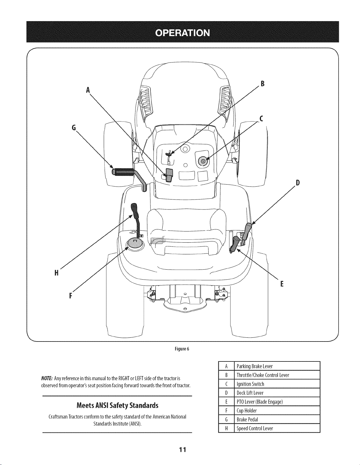
NOTE:Anyreferenceinthismanualto the RIGHTor LEFTsideof thetractoris
observedfromoperator'sseatpositionfacingforwardtowardsthe front of tractor.
MeetsANSiSafetyStandards
CraftsmanTractorsconformto thesafetystandardofthe AmericanNational
StandardsInstitute(ANSI).
A ParkingBrakeLever
B Throttle/ChokeControlLever
C IgnitionSwitch
D DeckLift Lever
E PTOLever(BladeEngage)
F CupHolder
G BrakePedal
H SpeedControlLever
11
Parking Brake
Tosetthe parkingbrake,fully depressthe parkingbrakepedal.Movethe parking
brakeleverintothe ONposition.Releasethe parkingbrakepedalto allowthe
parkingbraketo engage.
Toreleasethe parkingbrake,depressthe parkingbrakepedalandmovethe
parkingbrakeleveroutof the ONpositionandintotheOFFposition.
flOTE:Theparkingbrakemustbesetif theoperatorleavestheseatwith theengine
runningorthe enginewill automaticallyshutoff.
Throttle/chokeControl Lever
Thethrottle/chokecontrolleverislocatedonthe right sideof the
tractor'sdashpanel.Thislevercontrolsthespeedof theengineand,
whenpushedall the wayforward,thechokecontrolalso.When
setinagivenposition,thethrottle will maintaina uniformengine
speed.
IM PORTANT: Whenoperatingthetractorwith thecutting
deckengaged,becertainthatthe throttle leverisalwaysinthe
FAST(rabbit)position.
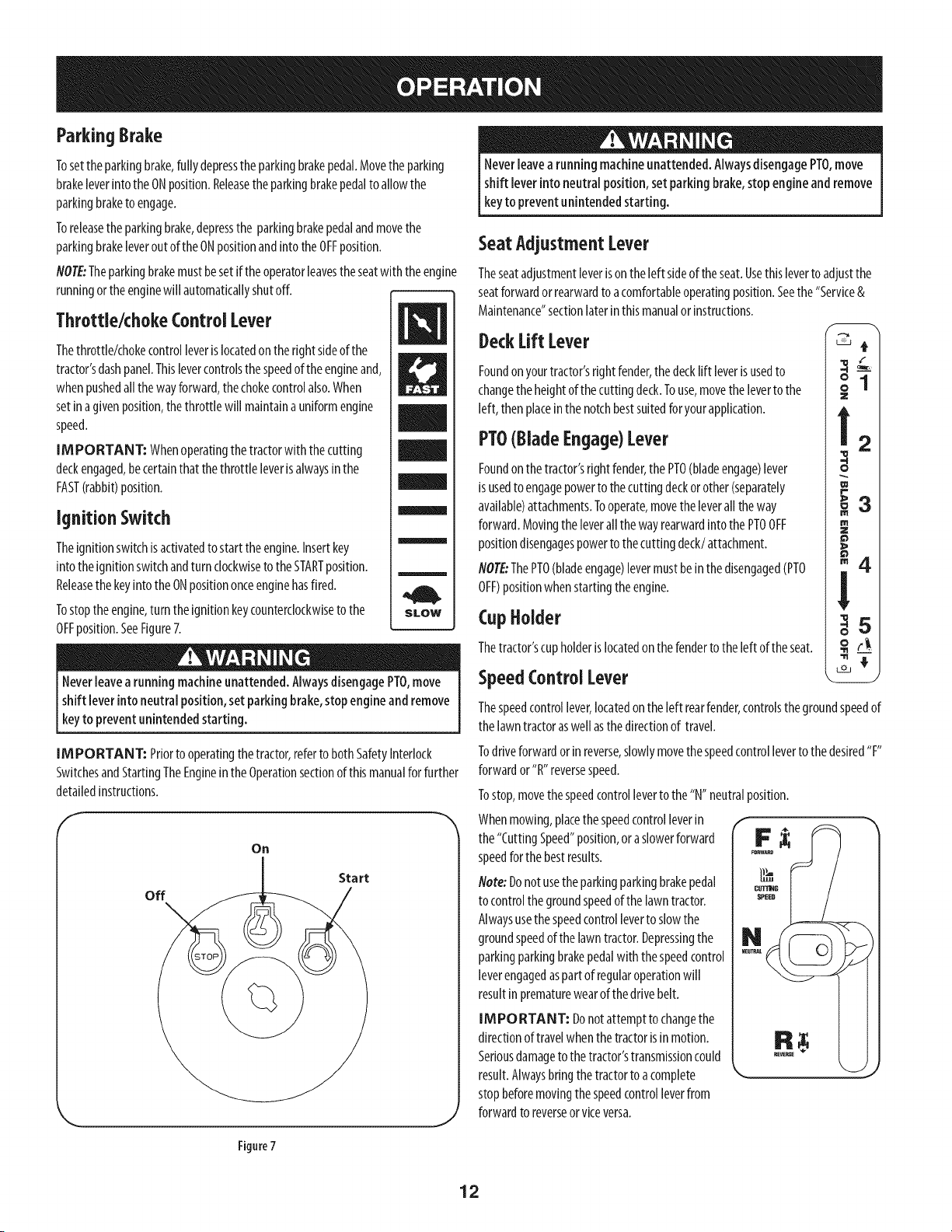
Ignition Switch
Theignitionswitchis activatedto startthe engine.Insertkey
into theignitionswitchandturn clockwiseto the STARTposition.
Releasethekeyintothe ONpositiononceenginehasfired.
Tostoptheengine,turn the ignitionkeycounterclockwiseto the
OFFposition.SeeFigure7.
Neverleavea runningmachineunattended.AlwaysdisengagePTO,move
shift leverinto neutralposition, set parkingbrake,stop engineand remove
keyto prevent unintended starting.
IM PORTANT: Priortooperatingthe tractor,referto bothSafetyInterlock
SwitchesandStartingTheEngineintheOperationsectionof thismanualforfurther
detailedinstructions.
Oil
off
Start
J
Neverleavea runningmachineunattended.AlwaysdisengagePTO,move
shift lever into neutralposition, setparking brake,stopengine andremove
keyto preventunintended starting.
SeatAdjustmentLever
Theseatadjustmentleverisonthe left sideoftheseat.Usethisleverto adjustthe
seatforwardor rearwardto acomfortableoperatingposition.Seethe "Service&
Maintenance"sectionlaterinthis manualorinstructions.
DeckLift Lever
Foundon yourtractor'srightfender,thedecklift leverisusedto
changetheheightof thecuttingdeck.Touse,movethe levertothe
left, thenplaceinthe notchbestsuitedforyourapplication.
PTO(Blade Engage)Lever
Foundon thetractor'srightfender,thePT0(bladeengage)lever
is usedto engagepowerto thecuttingdeckorother(separately
available)attachments.Tooperate,movethe leverall theway
forward.Movingthe leverall thewayrearwardintothe PT0OFF
positiondisengagespowerto thecutting deck/attachment.
NOTE-ThePT0(bladeengage)levermustbein thedisengaged(PT0
OFF)positionwhen startingtheengine.
CupHolder
Thetractor'scupholderislocatedon thefenderto the left of theseat.
SpeedControl Lever
Z
m m
o
W
m
z
o
Thespeedcontrollever,locatedon the left rearfender,controlsthegroundspeedof
thelawntractoraswellasthedirectionof travel.
Todriveforwardorinreverse,slowlymovethespeedcontrolleverto the desired"F"
forwardor"R" reversespeed.
Tostop,movethespeedcontrolleverto the "N" neutralposition.
Whenmowing,placethe speedcontrolleverin
the"CuttingSpeed"position,oraslowerforward
speedforthe bestresults.
flote: Donotusethe parkingparkingbrakepedal
to controlthegroundspeedofthelawntractor.
Alwaysusethespeedcontrolleverto slowthe
groundspeedof the lawntractor.Depressingthe
parkingparkingbrakepedalwith thespeedcontrol
leverengagedaspartof regularoperationwill
resultinprematurewearof the drivebelt.
IMPORTANT: Donot attemptto changethe
directionoftravelwhenthetractorisinmotion.
Seriousdamageto the tractor'stransmissioncould
result.Alwaysbringthetractorto acomplete
stopbeforemovingthespeedcontrolleverfrom
forwardto reverseor viceversa.
Figure7
12

ParkingBrakePedal& Lever
Theparkingparkingbrakepedalislocatedonthe left siderunning
boardofthe lawntractor.It isusedto bothsetthe parkingbrake
andto stopthelawntractorin suddensituations.
Theparkingbrakeleverislocatedonthe left sideof the tractor's
dashpanel.Tosettheparkingbrake,fullydepressthe parking
parkingbrakepedal.Movetheparkingbrakeleverall the way
downandintothe parkingbrakepositionandthen releasethe
parkingbrakepedalto allowthe parkingbraketo engage.
Toreleasethe parkingbrake,depressthe parkingbrakepedaland
theparkingbrakeleverwill automaticallymoveoutof the parking
brakeposition.
Inan suddensituation,fullydepressthe parkingbrakepedalto
bringthe tractorto astopandthenimmediatelymovethespeed
controlleverto the"N" neutralposition
IMPORTANT: Donot usethe parkingparkingbrakepedalto
controlthegroundspeedof thelawntractor.Doingsowill resultin
prematurewearof drivebelt.AlwaysusetheSpeedControlLever
to controlthegroundspeedof thelawntractorandto stopthetractorundernormal
circumstances.
Note:Theparkingparkingbrakepedalmustbedepressedto startthe engine.
Theparkingbrakemustalsobe setif theoperatorleavesthe seatwith theengine
runningorthe enginewill automaticallyshutoff.Referto SafetyInterlockSwitches
laterinthissection.
Oil
IMPORTANT: Yourtractor isshippedwith motoroil inthe engine.However,
youMUSTchecktheoil levelbeforeoperating.Becarefulnotto overfill.
Forinstructionsonhowto checkthe engineoil,referto CheckingTheEngine0il in
theServiceandMaintenancesectionof thismanual.
Gasoline
Thegasolinetankislocatedunderthehood.Donotoverfill.
Useextreme carewhen handling gasoline.Gasolineisextremelyflammable
andthe vaporsareexplosive.Neverfuel machineindoorsor while the
engineishot or running.Extinguishcigarettes,cigars,pipes,andother
sourcesof gn t on.
NOTE:Purchasegasolinein smallquantities.Donotusegasolineleft overfromthe
previousseason,to minimizegumdepositsinthefuel system.
Thisengineiscertifiedto operateon unleadedgasoline.Forbestresults,fill
thefueltank with onlyclean,fresh,unleadedgasolinewith apumpsticker
octaneratingof 87or higher.
Gasohol(upto 10%ethyl alcohol,90%unleadedgasolinebyvolume)isan
approvedfuel.Othergasoline/alcoholblends,suchasE85,arenotapproved.
MethylTertiaryButylEther(MTBE)andunleadedgasolineblends(upto a
maximumof 15%MTBEbyvolume)areapprovedfuels.Othergasoline/ether
blendsarenotapproved.
Fillfueltank outdoorsor inwell-ventilatedarea.
Donotoverfill fueltank.Filltankto no morethan 1/2inchbelowbottomof
filler neckto allowspacefor fuelexpansion.
Neverremovegascaporaddfuelwhilethe engineishotorrunning.Allow
engineto coolatleasttwo minutesbeforerefueling.
Ifgasolineisspilled,wipeit offthe engineandequipment.Movemachineto
anotherarea.Wait5 minutesbeforestartingtheengine.
Turnthe engineoff andlet enginecoolat least2 minutesbeforeremoving
thefuel cap.Thegasolinetankisunderthehood,with thefuel fill cap
locatedontheleft handsideof thetank.
2. Fillthefueltankwith gasoline.
3. Reinstallthefuel cap.
Note:STOPfilling tankoncefuel isseeninsidethe filler neck.Thisensuresthata
properexpansionvolumeiscreated,otherwisethe fuel canoverflowcreatinga
hazardoussituation. DoNOTfill to the topof the filler neck.SeeFigure8.
/
J
Figure 8
Avoid SeriousInjury or Death
Goupanddownslopes,not across.
Avoidsuddenturns.
Donotoperatetheunitwhereit couldslipor tip.
If machinestopsgoinguphill,stopbladesandbackdownhillslowly.
Donotmowwhenchildrenor othersarearound.
Nevercarrychildren,evenwith bladesoff.
Lookdown andbehindbeforeandwhilebacking.
Keepsafetydevices(guards,shields,andswitches)inplaceandworking.
Removeobjectsthat couldbethrown bytheblades.
Knowlocationandfunctionof all controls.
Besurebladesandenginearestoppedbeforeplacinghandsor feet near
blades.
Beforeleavingoperator'sposition,stoptractor,disengageblades,engage
parkingbrake,shutengineoff,andremovekey.
ReadOperator's Manual
13
Safety interlock System
Thesafetyinterlocksystemisdesignedforsafeoperationof the tractor.If this
systemshouldevermalfunction,do notoperatethetractor,immediatelycontact
1-800-4-MY-HOMEto havethe systemserviced.
Thesafetyinterlocksystempreventsthe enginefromstartingunless
theparkingbrakeisengagedandthe PTO(BladeEngage)leverisin the
disengaged(OFF)position.
Thesafetyinterlocksystemwillautomaticallyshutoffthe engineif the
operatorleavestheseatbeforeengagingtheparkingbrake.
Thesafetyinterlocksystemwillautomaticallyshutoff theengineif the
operatorleavesthetractor'sseatwith thePTO(BladeEngage)leverengaged,
regardlessof whethertheparkingbrakeisengaged.
Engagingthe ParkingBrake
To engage the parking brake:
1. Fullydepressthe parkingparkingbrakepedalandholdit downwith your
foot.
2. Movetheparkingbrakeleverall the waydownandinto theparkingbrake
(ON)position.
3. Releasethe parkingparkingbrakepedalto allowtheparkingbraketo
engage.
To release the parkingbrake:
1. Depressthe parkingparkingbrakepedalandmovethe parkingbrakelever
outof the parkingbrake(ON)positionandinto the OFFposition.
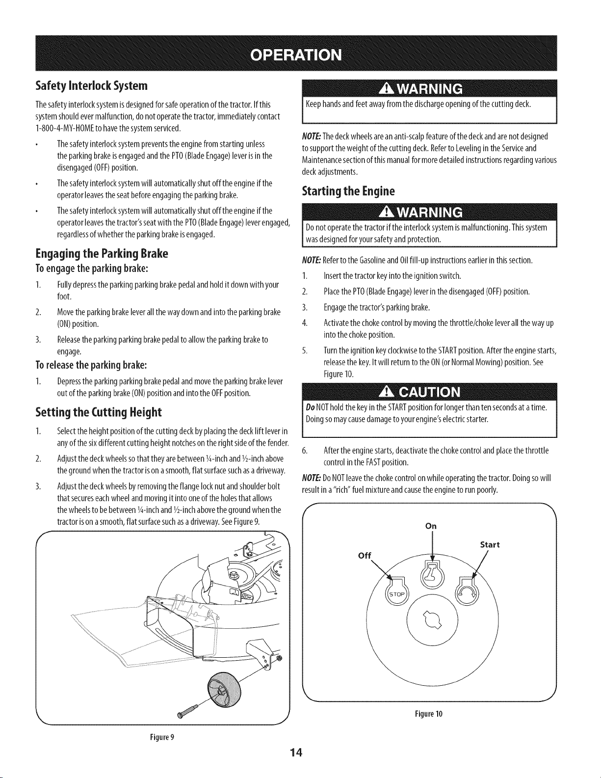
Setting the CuttingHeight
1. Selectthe heightpositionof the cuttingdeckbyplacingthe decklift leverin
anyof the sixdifferentcuttingheightnotcheson the right sideof thefender.
2. Adjustthe deckwheelssothattheyarebetween1g-inchand1/2-inchabove
thegroundwhenthetractorisonasmooth,flat surfacesuchasa driveway.
3. Adjustthe deckwheelsbyremovingtheflangelocknutandshoulderbolt
thatsecureseachwheelandmovingit into oneof theholesthat allows
thewheelsto be between1g-inchand1/2-inchabovethegroundwhenthe
tractorisonasmooth,flat surfacesuchasa driveway.SeeFigure9.
f
Keephandsandfeetawayfrom thedischargeopeningof thecuttingdeck.
NOTE:Thedeckwheelsareananti-scalpfeatureof thedeckandarenotdesigned
to supporttheweightof thecuttingdeck.Referto Levelinginthe Serviceand
Maintenancesectionof thismanualformoredetailedinstructionsregardingvarious
deckadjustments.
Starting the Engine
Donotoperatethe tractorif theinterlocksystemis malfunctioning.Thissystem
wasdesignedforyoursafetyandprotection.
NOTE:Referto theGasolineandOilfill-up instructionsearlierinthissection.
1. Insertthetractorkeyintothe ignitionswitch.
2. Placethe PTO(BladeEngage)leverinthe disengaged(OFF)position.
3. Engagethetractor'sparkingbrake.
4. Activatethe chokecontrolbymovingthe throttle/chokeleverall the wayup
intothechokeposition.
5. Turntheignitionkeyclockwiseto the STARTposition.Aftertheenginestarts,
releasethe key.It will returnto the ON(orNormalMowing)position.See
Figure10.
DoNOTholdthekeyinthe STARTpositionforlongerthantensecondsatatime.
Doingsomaycausedamageto yourengine'selectricstarter.
6. Afterthe enginestarts,deactivatethechokecontrolandplacethethrottle
controlinthe FASTposition.
NOTE:DoNOTleavethe chokecontrolonwhileoperatingthe tractor.Doingsowill
resultina"rich"fuel mixtureandcausethe engineto run poorly.
f
Oil
off
Start
Figure9
14
Figure10
Stopping the Engine
Ifyoustrikeaforeignobject,stopthe engine,disconnectthe sparkplugwire(s)
andgroundagainstthe engine.Thoroughlyinspectthe machineforanydamage.
Repairthedamagebeforerestartingandoperating
1. If thebladesareengaged,placethe PTO(BladeEngage)leverinthe
disengaged(OFF)position.
2. Turnthe ignitionkeycounterclockwiseto theSTOPposition.
3. Removethekeyfrom theignitionswitchto preventunintendedstarting.
DrivingTheTractor
Avoidsuddenstarts,excessivespeedandsuddenstops.
Donotleavethe seatofthe tractorwithoutfirst placingthePTO(BladeEngage)
leverinthedisengaged(OFF)position,depressingthebrakepedalandengaging
theparkingbrake.If leavingthe tractorunattended,alsoturn theignitionkeyoff
andremovethe key.
Alwayslookdownandbehindbeforeandwhilebackingupto avoida back-over
accident.
1. Movethethrottle leverintothe FAST(rabbit)position.
NOTE:Alwaysoperatethe tractorwith the throttle/chokecontrolleverinthe
FAST(rabbit)positionforthe mostefficientuseof thecuttingdeckorother
(separatelyavailable)attachments.
2. Releasethe parkingbrakebydepressingthe parkingbrakepedal
3. Slowlymovethespeedcontrolleverindesired"F"forwardor"R" reverse
position.Thefurtherforwardor rearwardthat theleverismoved,the faster
thetractorwill travel.
DoNOTattemptto changethedirectionof travelwhenthetractorisin motion.
Alwaysbringthe tractorto acompletestopbeforemovingthespeedcontrol
leverfrom forwardto reverseorviceversa.Failureto do socouldresultinserious
damageto yourtractor'stransmission.
IIViPO RTA N T: First-timeoperatorsshoulduseslowerspeeds.Become
completelyfamiliarwith the tractor'soperationandcontrolsbeforeoperatingthe
tractorat a higherspeed.
4. Tostop,movethe speedcontrolleverto the"N" neutralposition.
IMPORTANT: Inasuddensituation,fullydepressthe brakepedalto bring
thetractorto astopandthenimmediatelymovethe speedcontrolleverto the "N"
neutralposition.
Settheparkingbrakebyfullydepressingthe parkingbrakepedaland
keepingit depressedwhileplacingtheparkingbrakeleverinthe ON
position.Releasetheparkingbrakepedalto allowthe parkingbraketo
engage.
Beforeleavingthe operator'spositionforanyreason,disengagethe blades,place
thespeedcontrolleverin neutral,engagetheparkingbrake,shutengineoffand
removethe key.
IM PORTANT: Whenstoppingthetractorforanyreasonwhileon agrass
surface,always:
1. Placethe speedcontrolleverin N(neutral),
2. Engagethe parkingbrake,
3. Shutengineoff andremovethekey.
Doingsowill minimizethepossibilityof havingyourlawn"browned"byhot
exhaustfromyourtractor'srunningengine.
DrivingOn Slopes
Referto theSLOPEGAUGEintheImportantSafeOperationPracticessectionof the
manualto helpdetermineslopeswhereyou mayoperatethetractorsafely.
Donotmowon inclineswith aslopeinexcessof 15degrees(ariseof
approximately2-1/2feetevery10feet).Thetractorcouldoverturnandcause
seriousinjury.
Mow upanddownslopes,NEVERacross.
Exerciseextremecautionwhenchangingdirectiononslopes.
Watchforholes,ruts,bumps,rocks,or otherhiddenobjects.Uneventerrain
couldoverturnthemachine.Tallgrasscanhideobstacles.
Avoidturnswhendrivingonaslope.Iraturn mustbemade,turndown the
slope.Turningupaslopegreatlyincreasesthechanceof a rollover.
Avoidstoppingwhendrivingupa slope.If it isnecessaryto stopwhile
drivingupa slope,start upsmoothlyandcarefullyto reducethe possibility
of flippingthetractoroverbackward.
Engagingthe Blades
Engagingthe PTO(BladeEngage)transferspowerto the cuttingdeckor other
(separatelyavailable)attachments.Toengagethe blades,proceedasfollows:
1. Movethethrottle/chokecontrolleverto the FAST(rabbit)position.
2. Graspthe PTO(BladeEngage)leverandpivot it all thewayforwardinto the
engaged(ON)position.
3. Keepthethrottle leverintheFAST(rabbit)positionforthe mostefficientuse
of thecuttingdeckorother(separatelyavailable)attachments.
IM PORTANT: Inthe ReverseCautionModetheenginewill automaticallyshut
off ifthe PTOisengagedwith thespeedcontrolleverinpositionfor reversetravel
with the ignitionkeyin the NORMALMOWINGposition.
Usingthe DeckLift Lever
Toraisethe cuttingdeck,movethe decklift leverto theleft, thenplaceit inthe
notchbestsuitedforyourapplication.Referto SettingTheCuttingHeightearlierin
thissection.
15
Mowing
Tohelpavoidbladecontactor athrown objectinjury,keepbystanders,helpers,
I childrenandpetsat least75feetfromthe machinewhileit isinoperation.Stop
[ machineif anyoneentersthe area.
Thefollowinginformationwill behelpfulwhen usingthecuttingdeckwith your
tractor:
Planyourmowingpatternto avoiddischargeof materialstowardroads,
sidewalks,bystandersandthe like.Also,avoiddischargingmaterialagainstawall
orobstructionwhichmaycausedischargedmaterialto ricochetbacktowardthe
operator.
Donotmowat highgroundspeed,especiallyif amulchkit orgrasscollector
isinstalled.
Forbestresultsit isrecommendedthat the first two lapsbecutwith the
dischargethrowntowardsthecenter.Afterthe first two laps,reversethe
directionto throwthe dischargeto the outsideforthe balanceofcutting.
Thiswill givea betterappearanceto the lawn.
Donotcutthe grasstoo short.Shortgrassinvitesweedgrowthandyellows
quicklyin dryweather.
Mowingshouldalwaysbedonewith theengineat full throttle.
Underheavierconditionsit maybe necessaryto go backoverthecut areaa
secondtimeto get acleancut.
DoNOTattemptto mowheavybrushandweedsandextremelytallgrass.
Yourtractorisdesignedto mowlawns,NOTclearbrush.
Keepthe bladessharpandreplacethe bladeswhenworn.Referto Cutting
BladesintheServiceandMaintenencesectionof thismanualforproper
bladesharpeninginstructions.
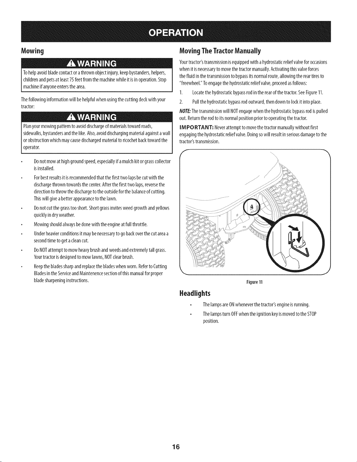
MovingTheTractorManually
Yourtractor'stransmissionisequippedwith a hydrostaticreliefvalveforoccasions
whenit isnecessaryto movethetractormanually.Activatingthisvalveforces
thefluid in thetransmissionto bypassits normalroute,allowingthe reartiresto
"freewheel."Toengagethe hydrostaticreliefvalve,proceedasfollows:
1. Locatethe hydrostaticbypassrodinthe rearof thetractor.SeeFigure11.
2. Pullthehydrostaticbypassrodoutward,thendown to lockit intoplace.
NOTE:Thetransmissionwill NOTengagewhenthehydrostaticbypassrodispulled
out. Returntherodto itsnormalpositionpriorto operatingthetractor.
IM PO RTANT: Neverattemptto movethe tractormanuallywithoutfirst
engagingthehydrostaticreliefvalve.Doingsowill resultinseriousdamageto the
tractor'stransmission.
Figure11
Headlights
ThelampsareONwheneverthe tractor'sengineisrunning.
Thelampsturn OFFwhentheignitionkeyismovedto theSTOP
position.
16
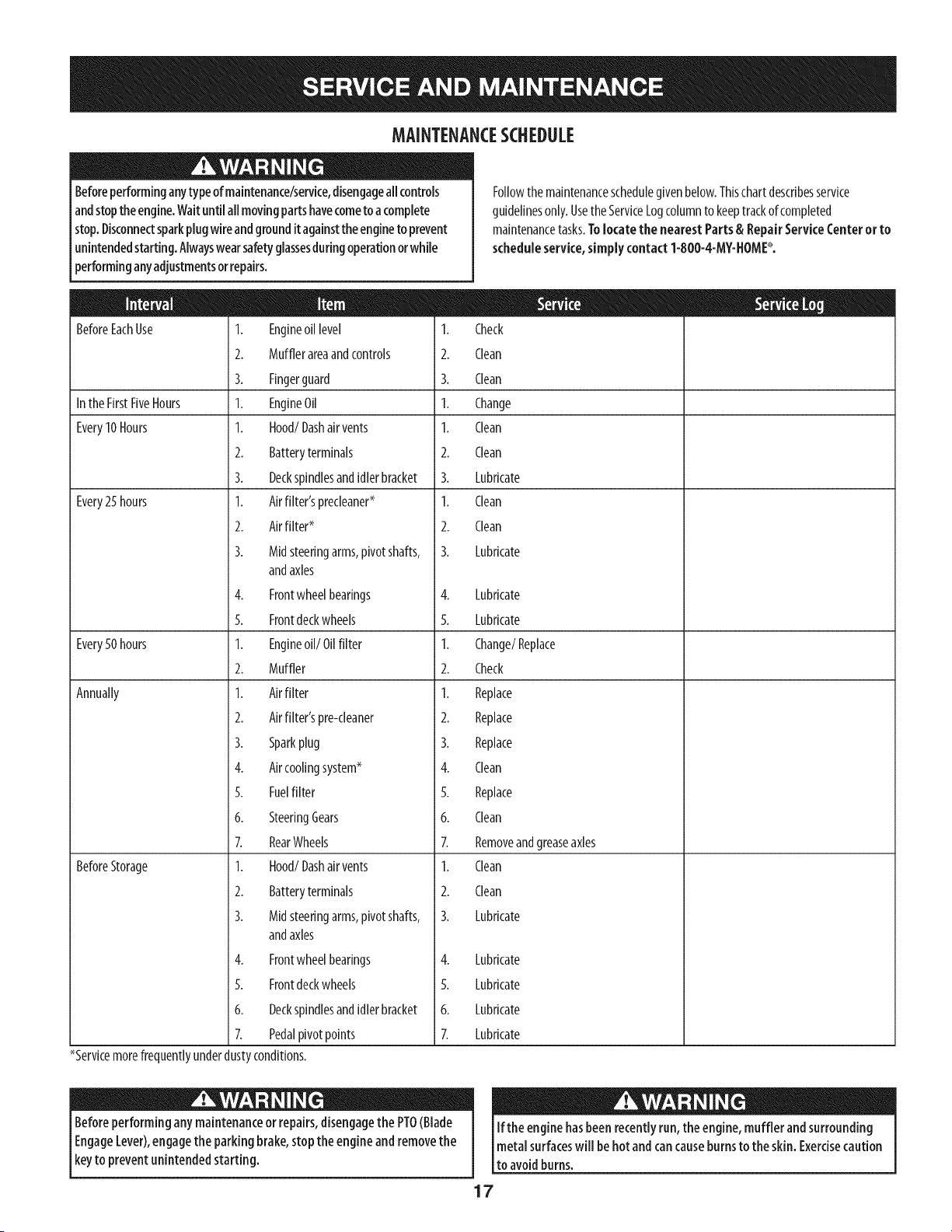
MAINTENANCESCHEDULE
Beforeperforminganytypeofmaintenance/service,disengageallcontrols
andstoptheengine.Waituntil all movingpartshavecometo acomplete
stop.Disconnectsparkplugwireandgrounditagainsttheengineto prevent
unintendedstarting.Alwayswearsafetyglassesduringoperationorwhile
performinganyadjustmentsorrepairs.
BeforeEachUse 1. Engineoil level 1.
2. Mufflerareaandcontrols 2.
3. Fingerguard 3.
Inthe FirstFiveHours 1. EngineOil 1.
Every10Hours I. Hood/Dashair vents I.
2. Batteryterminals 2.
3. Deckspindlesandidlerbracket 3.
Every25 hours 1. Airfilter'sprecleaner* 1.
2. Airfilter* 2.
3. Midsteeringarms,pivotshafts, 3.
andaxles
4. Frontwheelbearings 4.
5. Frontdeckwheels 5.
Every50 hours 1. Engineoil/Oil filter 1.
2. Muffler 2.
Annually 1. Airfilter 1.
2. Airfilter'spre-cleaner 2.
3. Sparkplug 3.
4. Aircoolingsystem* 4.
5. Fuelfilter 5.
6. SteeringGears 6.
7. RearWheels 7.
BeforeStorage 1. Hood/Dashair vents 1.
2. Batteryterminals 2.
3. Midsteeringarms,pivotshafts, 3.
andaxles
4. Frontwheelbearings
5. Frontdeckwheels
6. Deckspindlesandidlerbracket
7. Pedalpivotpoints
*Servicemorefrequentlyunderdustyconditions.
Followthe maintenanceschedulegivenbelow.Thischartdescribesservice
guidelinesonly.UsetheServiceLogcolumnto keeptrackofcompleted
maintenancetasks.Tolocate the nearest Parts & RepairServiceCenteror to
scheduleservice, simply contact1-800-4-MY-HOME_.
Check
Clean
Clean
Change
Clean
Clean
Lubricate
Clean
Clean
Lubricate
Lubricate
Lubricate
Change/Replace
Check
Replace
Replace
Replace
Clean
Replace
Clean
Removeandgreaseaxles
Clean
Clean
Lubricate
4. Lubricate
5. Lubricate
6. Lubricate
7. Lubricate
Beforeperformingany maintenanceor repairs,disengagethe PTO(Blade
EngageLever),engagethe parkingbrake,stopthe engine andremovethe
keyto prevent unintendedstarting.
If the enginehasbeen recentlyrun,the engine,muffler and surrounding
metal surfaceswill behot andcan causeburnsto the skin. Exercisecaution
to avoidburns.
17
EngineMaintenance
Checking the Engine Oil
Onlyusehighqualitydetergentoil ratedwith APIserviceclassificationSF,SG,
SH,or SJ.Selecttheoil'sSAEviscositygradeaccordingto theexpectedoperating
temperature.Followthechartbelow.Althoughmulti-viscosityoils (5W20,10W30,
etc.)improvestartingin coldweather,theywill resultinincreasedoil consumption
whenusedabove32°I.Checkyourengineoil levelmorefrequentlyto avoidpossible
enginedamagefromrunninglowon oil.
_ow-so__[___
SAE 30 m
_mm 5W-30
L
[°F} -200 0° 20°32 °400 500 60° 80° I00 °
{°C)-30°-20°-10 ° 0° 10o 20° 300 400
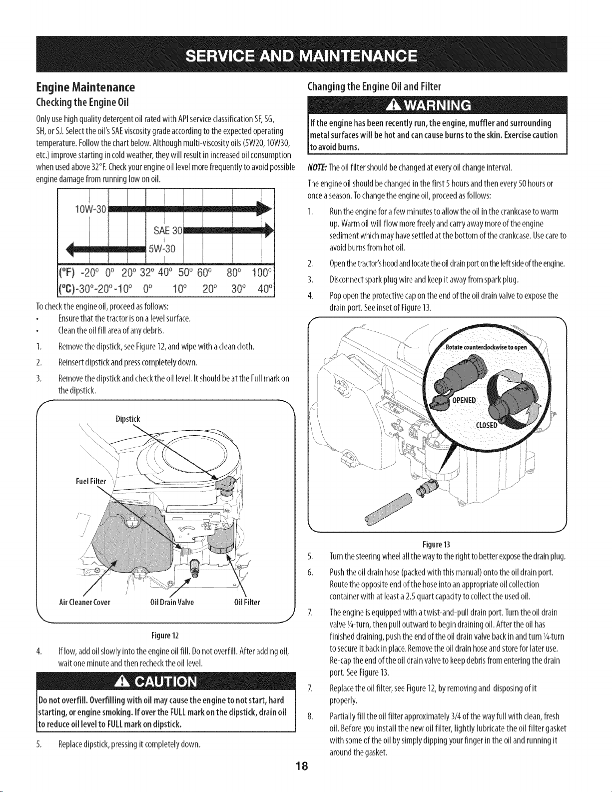
Tocheckthe engineoil,proceedasfollows:
Ensurethat thetractorison alevelsurface.
Cleantheoil fill areaof anydebris.
1. Removethedipstick,seeFigure12,andwipewith acleancloth.
2. Reinsertdipstickandpresscompletelydown.
3. Removethedipstickandcheckthe oil level.Itshouldbeat theFullmarkon
thedipstick.
Changing the Engine Oil and Filter
If the enginehasbeenrecently run, the engine,muffler andsurrounding
metal surfaceswill be hot andcancauseburnsto theskin. Exercisecaution
to avoidburns.
NOTE:Theoil filter shouldbechangedat everyoil changeinterval.
Theengineoilshouldbechangedin thefirst 5hoursandthenevery50 hoursor
onceaseason.Tochangethe engineoil,proceedasfollows:
1. Runtheengineforafew minutesto allow theoil inthe crankcaseto warm
up.Warmoil will flow morefreelyandcarryawaymoreof theengine
sedimentwhichmayhavesettledatthe bottomof the crankcase.Usecareto
avoidburnsfrom hot oil.
2. Openthetractor'shoodandlocatetheoil drainportontheleftsideoftheengine.
3. Disconnectsparkplug wireandkeepit awayfromsparkplug.
4. Popopentheprotectivecapon theendofthe oil drainvalveto exposethe
drainport. Seeinsetof Figure13.
Dipstick
FuelFilter
// 7
//
AirCleanerCover OilDrainValve OilFilter
Figure12
4. If low,addoil slowlyinto the engineoil fill. Donotoverfill.Afteraddingoil,
waitoneminuteandthenrechecktheoil level.
Donotoverfill. Overfilling with oil maycausethe engineto not start, hard
starting, orengine smoking. If overthe FULLmark on the dipstick,drain oil
to reduceoii levelto FULLmark on dipstick.
5. Replacedipstick,pressingit completelydown.
5.
6.
18
Figure13
Turnthe steeringwheelallthewayto therightto betterexposethedrainplug.
Pushtheoil drainhose(packedwith thismanual)ontotheoil drainport.
Routetheoppositeendofthehoseinto an appropriateoil collection
containerwith at leasta 2.5quartcapacityto collecttheusedoil.
Theengineisequippedwith atwist-and-pulldrainport. Turnthe oil drain
valveY4-turn,then pulloutwardto begindrainingoil.Afterthe oil has
finisheddraining,pushtheendof the oil drainvalvebackinandturn Y4-turn
to secureit backinplace.Removetheoil drainhoseandstorefor lateruse.
Re-captheendofthe oil drainvalveto keepdebrisfromenteringthedrain
port.SeeFigure13.
Replacetheoil filter,seeFigure12,byremovingand disposingof it
properly.
Partiallyfill the oil filterapproximately3/4of thewayfull with clean,fresh
oil. Beforeyou installthenewoil filter, lightly lubricatetheoil filter gasket
with someof the oil bysimplydippingyourfinger inthe oil andrunningit
aroundthe gasket.
10.
Installtheoilfilterbyhanduntilthegasketcontactstheoilfilteradapter,
thentightentheoilfilter1/2to3/4turns.
Refilltheenginewithnewmotoroiluntiltheoillevelonthedipstickreads
FULL.Replacetheoilfillcap/dipstick.
Usedoilisahazardouswaste product. Disposeof usedoil properly.Donot
discardwith householdwaste.Checkwithyour iota[ authorities or orcontact
1-800-4-MY-HOMEfor a listof safe disposal/recyclingfacilities.
11. Startandruntheengine.Astheenginewarmsup,checkforoilleaks.
12. Stopthe engineandchecktheoil level.It shouldbeat the FULLmarkonthe
dipstick.
Fuel Filter
Gasolineandits vapors areextremely flammable andexplosive.Fireor
explosioncan causesevereburns or death.
Keepgasolineawayfromsparks,openflames,pilot lights,heat,andother
ignitionsources.
Checkfuellines,tank,cap,andfittingsfrequentlyforcracksor leaks.Replace
if necessary.
Beforereplacingthe fuelfilter, drainthefuel tank asperthe instructions
below.
Donotdrainfuel whentheengineishot.Allowtheengineadequatetimeto
cool.Drainfuelinto anapprovedcontaineroutdoors,awayfromopenflame.
Drainanylargevolumeoffuel from thetankbydisconnectingthefuel line
fromthe in-linefuelfilter nearthe engine.
Removethe fuel linefromthe In-lineside(sidetowardsthefuel tank)of the
fuelfilter.
Replacementpartsmustbethe sameandinstalledinthe samepositionas
theoriginalparts.
If fuelspills,wait until it evaporatesbeforestartingengine.
Beforereplacingthe fuelfilter, drainthefuel tank.Otherwise,fuelcanleak
outandcauseafire orexplosion.
ToDrain the fuel:
Locatethefuel filter,seeFigure12,whichisroutedontheleft sideofthe
enginebetweenthe fueltankandthecarburetor,andmaybeattachedto the
enginewithatie strap.Cutthetiestrap,if present,thenpinchthe tabsonthe
in-lineclamponthefuelfilterwith apairof pliers,slidetheclampupthe fuel
line.Pullthefuel linefreefromthefilterandplacetheopenendof thelineinto
anapprovedcontainertodrainthefuel.
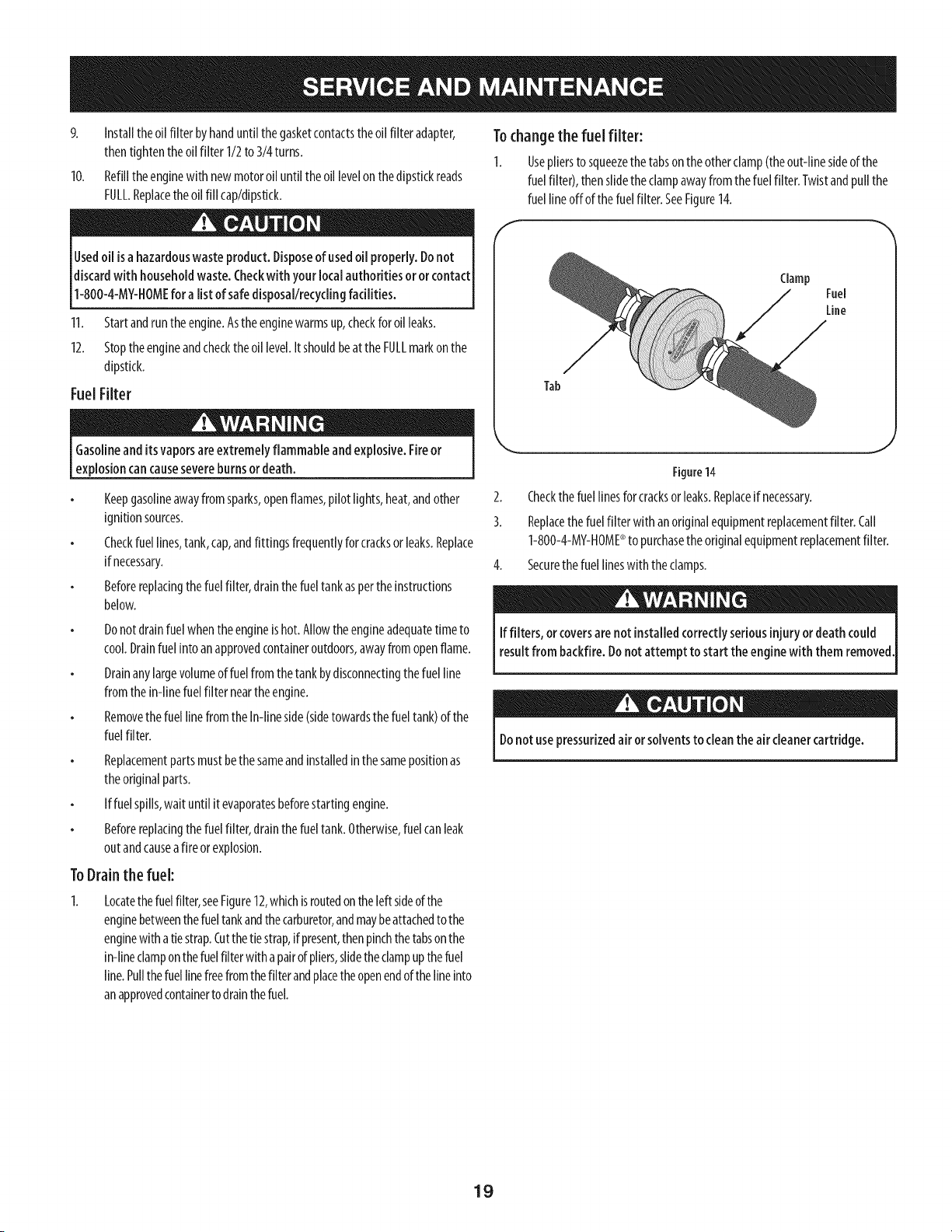
Tochangethe fuel filter:
I. Usepliersto squeezethe tabsontheotherclamp(theout-linesideof the
fuelfilter), thenslidetheclampawayfrom the fuelfilter. Twistandpullthe
fuel lineoffof the fuelfilter.SeeFigure14.
f
Tab
Clamp
Fuel
Line
J
Figure14
2. Checkthe fuellinesforcracksorleaks.Replaceif necessary.
3. Replacethe fuel filter withan originalequipmentreplacementfilter. Call
1-800-4-MY-HOME®to purchasethe originalequipmentreplacementfilter.
4. Securethe fuel lineswith theclamps.
If filters, orcoversarenot installed correctlyseriousinjury ordeath could
resultfrom backfire.Donot attempt to start the enginewith them removed
Donot usepressurizedair orsolventsto cleanthe air cleanercartridge.
19
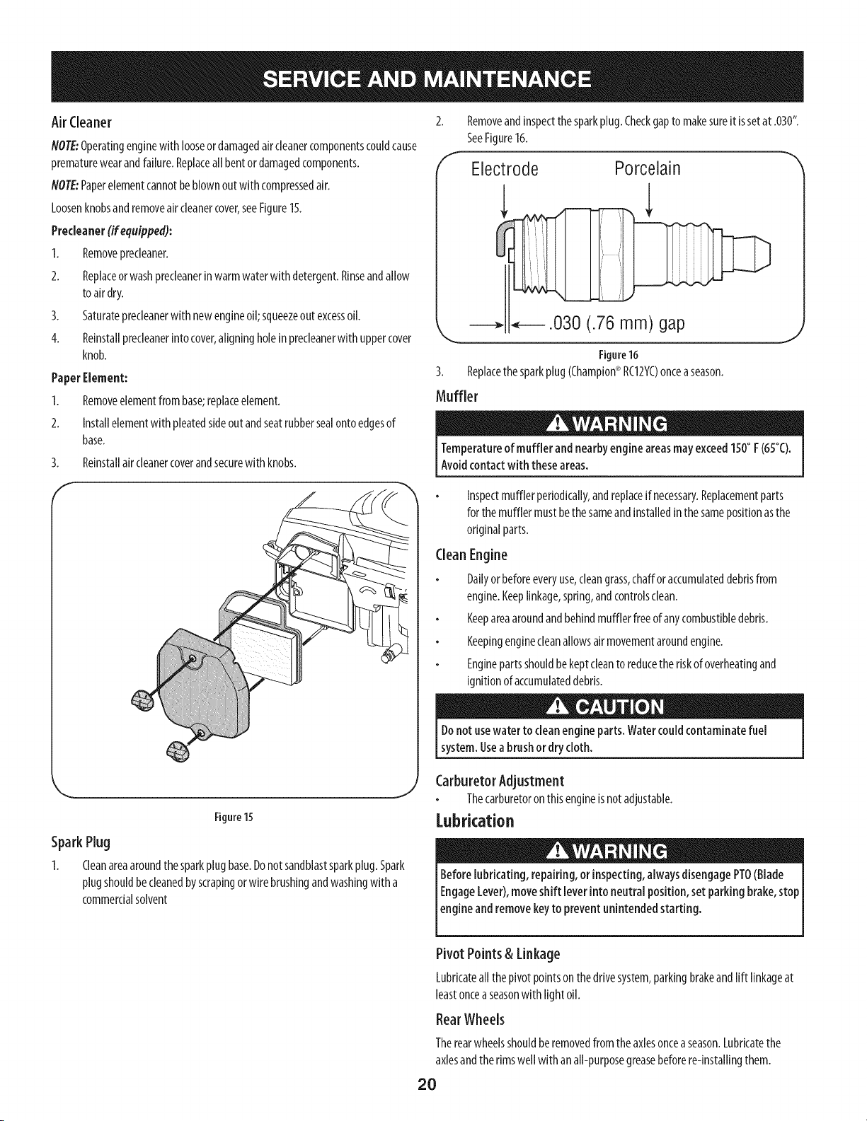
Air Cleaner
NOTE:Operatingenginewith looseor damagedaircleanercomponentscouldcause
prematurewearandfailure.Replaceall bentordamagedcomponents.
NOTE:Paperelementcannotbe blownoutwith compressedair.
Loosenknobsandremoveair cleanercover,seeFigure15.
Precleaner(ifequipped):
1. Removeprecleaner.
2. Replaceor washprecleanerinwarmwaterwith detergent.Rinseandallow
to airdry.
3. Saturateprecleanerwith newengineoil;squeezeout excessoil.
4. Reinstallprecleanerintocover,aligningholein precleanerwith uppercover
knob.
PaperElement:
1. Removeelementfrombase;replaceelement.
2. Installelementwith pleatedsideoutandseatrubbersealontoedgesof
base.
3. Reinstallair cleanercoverandsecurewith knobs.
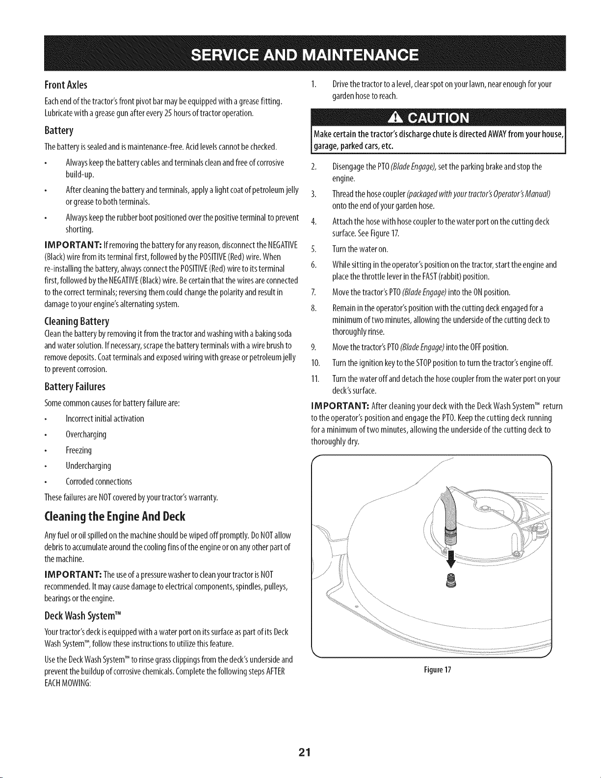
Removeandinspectthesparkplug.Checkgapto makesureit issetat .030".
SeeFigure16.
Electrode Porcelain
.030 (.76 mm) gap
Figure16
3. Replacethesparkplug (Champion®RC12YC)onceaseason.
Muffler
J
Temperatureof muffler and nearbyengineareasmayexceed150° F(65°C).
Avoidcontact with theseareas.
Inspectmufflerperiodically,andreplaceif necessary.Replacementparts
for themufflermustbethesameandinstalledinthesamepositionasthe
originalparts.
CleanEngine
Dailyorbeforeeveryuse,cleangrass,chafforaccumulateddebrisfrom
engine.Keeplinkage,spring,andcontrolsclean.
Keepareaaroundandbehindmufflerfreeofanycombustibledebris.
Keepingenginecleanallowsairmovementaroundengine.
Enginepartsshouldbe keptcleanto reducetheriskof overheatingand
ignitionof accumulateddebris.
Figure 15
SparkPlug
1. Cleanareaaroundthe sparkplugbase.Donotsandblastsparkplug.Spark
plugshouldbecleanedbyscrapingorwire brushingandwashingwith a
commercialsolvent
Donotusewater to cleanengine parts. Watercould contaminatefuel
system.Usea brushor dry cloth.
Carburetor Adjustment
Thecarburetoron thisengineisnotadjustable.
Lubrication
Beforelubricating, repairing,or inspecting,alwaysdisengagePTO(Blade
EngageLever),moveshift leverinto neutral position, set parking brake,stop
l eng ne andremovekeyto prevent un ntended start rig.
Pivot Points& Linkage
Lubricateall the pivotpointsonthedrivesystem,parkingbrakeandlift linkageat
leastonceaseasonwith light oil.
Rear Wheels
Therearwheelsshouldberemovedfromthe axlesonceaseason.Lubricatethe
axlesandtherimswellwith an all-purposegreasebeforere-installingthem.
20
FrontA×les
Eachendof thetractor'sfront pivot barmaybeequippedwith agreasefitting.
Lubricatewith agreasegunafter every25 hoursoftractoroperation.
Battery
Thebatteryis sealedandismaintenance-free.Acidlevelscannotbechecked.
Alwayskeepthebatterycablesandterminalscleanandfreeof corrosive
buiN-up.
Aftercleaningthe batteryandterminals,applya lightcoatof petroleumjelly
orgreaseto bothterminals.
Alwayskeeptherubberbootpositionedoverthe positiveterminalto prevent
shorting.
IMPORTANT: Ifremovingthe batteryforanyreason,disconnecttheNEGATIVE
(Black)wirefromits terminalfirst,followedbythePOSITIVE(Red)wire.When
re-installingthe battery,alwaysconnectthePOSITIVE(Red)wireto itsterminal
first,followedbytheNEGATIVE(Black)wire.Becertainthatthewiresareconnected
to thecorrectterminals;reversingthemcouldchangethe polarityandresultin
damagetoyourengine'salternatingsystem.
CleaningBattery
Cleanthe batterybyremovingit fromthetractorandwashingwith a bakingsoda
andwatersolution.If necessary,scrapethe batteryterminalswith awirebrushto
removedeposits.Coatterminalsandexposedwiring with greaseor petroleumjelly
to preventcorrosion.
Battery Failures
Somecommoncausesfor batteryfailureare:
Incorrectinitialactivation
Overcharging
Freezing
Undercharging
Corrodedconnections
ThesefailuresareNOTcoveredbyyourtractor'swarranty.
Cleaning the EngineAnd Deck
Anyfuel oroil spilledonthemachineshouldbewipedoff promptly.DoNOTallow
debristo accumulatearoundthecoolingfinsof theengineoronanyotherpartof
themachine.
IM PORTANT: Theuseof apressurewasherto cleanyourtractorisNOT
recommended.It maycausedamageto electricalcomponents,spindles,pulleys,
bearingsor theengine.
DeckWashSystemTM
Yourtractor'sdeckisequippedwithawaterportonitssurfaceaspartofitsDeck
WashSystemTM, followtheseinstructionstoutilizethisfeature.
UsetheDeckWashSystemTM torinsegrassclippingsfromthedeck'sundersideand
preventthebuildupofcorrosivechemicals.CompletethefollowingstepsAFTER
EACHMOWING:
Drivethe tractorto a level,clearspotonyourlawn,nearenoughforyour
gardenhoseto reach.
Makecertain the tractor'sdischargechute isdirected AWAYfrom your house,
garage,parkedcars,etc.
2. DisengagethePTO(BladeEngage),settheparkingbrakeandstopthe
engine.
3. Threadthehosecoupier(packagedwithyourtractor'sOperator'sManual)
ontotheendofyourgardenhose.
4. Attachthehosewithhosecouplertothewaterportonthecuttingdeck
surface.SeeFigure17.
Turnthewateron.5.
6.
Whilesitting inthe operator'spositiononthe tractor,starttheengineand
placethe throttle leverintheFAST(rabbit)position.
7. Movethetractor'sPTO(BladeEngage)into the ONposition.
8. Remainintheoperator'spositionwith thecuttingdeckengagedfora
minimumof two minutes,allowingtheundersideof the cuttingdeckto
thoroughlyrinse.
9. Movethetractor'sPTO(BladeEngage)intothe0FFposition.
10. Turnthe ignitionkeyto the STOPpositionto turn thetractor'sengineoff.
11. Turnthe wateroff anddetachthehosecouplerfrom the waterporton your
deck'ssurface.
IMPORTANT: After cleaningyourdeckwith the DeckWashSystemTM return
to the operator'spositionandengagethe PTO.Keepthe cutting deckrunning
for a minimumof two minutes,allowing theundersideof the cutting deckto
thoroughlydry.
Figure17
21
Adjustments
Neverattempt to makeany adjustmentswhile the engineis running, except
wherespecified inthe operator'smanual.
Levelingthe Deck
Note:Checkthetractor'stirepressurebeforeperforminganydeckleveling
adjustments.RefertoTiresintheServicesectionofthismanualformore
informationregardingtirepressure.
Front ToRear
Thefront ofthe cuttingdeckissupportedbyastabilizerbarthatcanbeadjustedto
levelthe deckfrom front to rear.Thefront ofthe deckshouldbebetweenIA-inch
and_8-lnchlowerthantherearof the deck.Adjustif necessaryasfollows:
I. Withthetractorparkedon afirm, levelsurface,placethe leverforlifting the
platformonthe secondto the topnotch(secondhighestposition)androtate
thebladeascloseaspossibleto thedischargechannelthat isparallelto the
tractor.
2. Measurethe distancefrom thefront of the bladetip to thegroundandthe
rearofthebladetip to theground.Thefirst measurementtakenshould
bebetweenIA"and3/8"lessthanthesecondmeasurement.Determine
theapproximatedistancenecessaryfor properadjustmentandproceed,if
necessary,to thenext step.
3. Locatetheflangelocknuton thefront sideofthestabilizerbracket.See
Figure18.
Tightenthe flangelocknutto raisethefront of thedeck;
Loosenthe flangelocknutto lowerthefront ofthedeck.
J
,.. J
Figure18
SidetoSide
If the cuttingdeckappearsto bemowingunevenly,asideto sideadjustmentcanbe
performed.Adjustif necessaryasfollows:
1. With the tractorparkedon afirm, levelsurface,placethe decklift leverin
thesecondfrom the topnotch(secondhighestposition)androtateboth
bladessothattheyareperpendicularwith thetractor.
2. Measurethedistancefromtheoutsideofthe left bladetip to theground
andthedistancefrom theoutsideof theright bladetip to theground.Both
measurementstakenshouldbeequal.Ifthey'renot,proceedto the next
step.
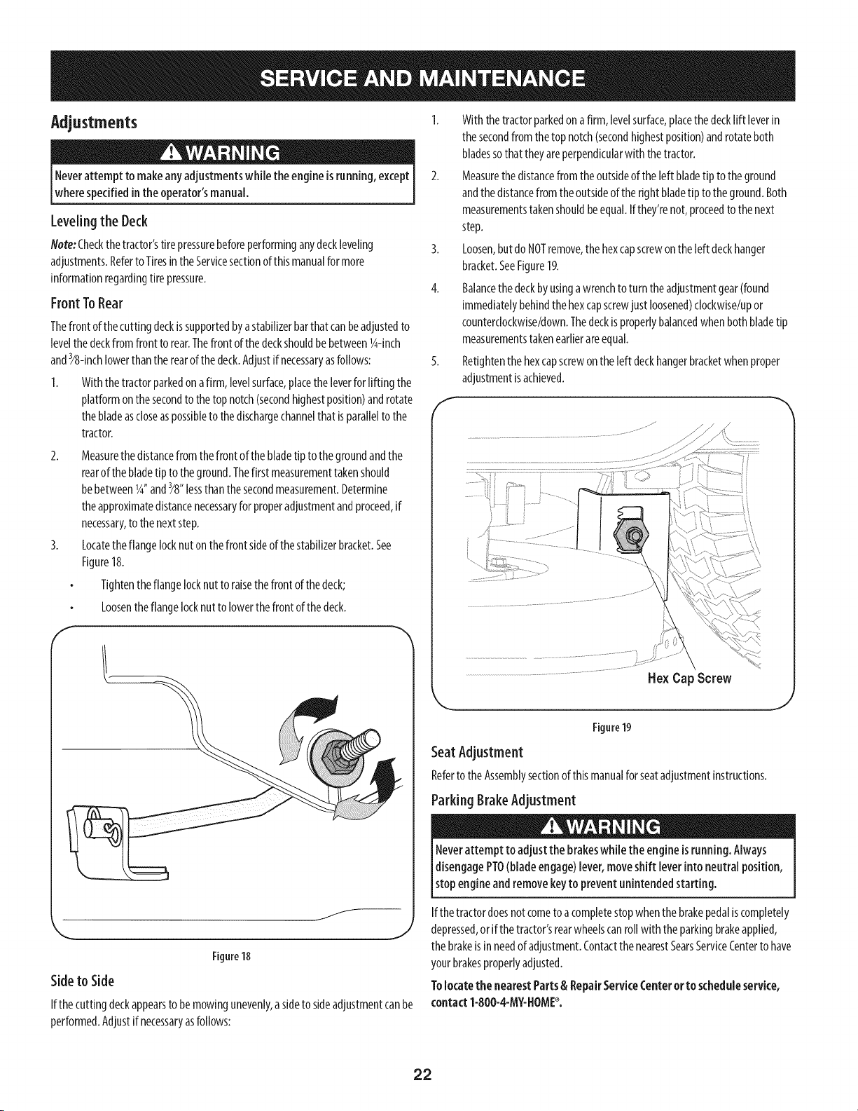
3. Loosen,but do NOTremove,the hexcapscrewonthe left deckhanger
bracket.SeeFigure19.
4. Balancethe deckbyusingawrenchto turn theadjustmentgear(found
immediatelybehindthe hexcapscrewjust loosened)clockwise!upor
counterclockwise/down.Thedeckisproperlybalancedwhenbothbladetip
measurementstakenearlierareequal.
S. Retlghtenthe hexcapscrewonthe left deckhangerbracketwhenproper
adjustmentisachieved.
He× Cap Screw
Figure19
Seat Adjustment
Referto theAssemblysectionof thismanualforseatadjustmentinstructions.
Parking BrakeAdjustment
Neverattempt to adjustthe brakeswhilethe engineisrunning.Always
IdisengagePTO(bladeengage)lever,moveshift leverinto neutralposition,
Istopengine and removekeyto prevent unintendedstarting.
Ifthe tractordoesnot cometo acompletestopwhenthebrakepedaliscompletely
depressed,or if thetractor'srearwheelscanroll with theparkingbrakeapplied,
thebrakeis inneedof adjustment.ContactthenearestSearsServiceCenterto have
yourbrakesproperlyadjusted.
Tolocatethe nearestParts& RepairServkeCenteror to scheduleservke,
contact1-800-4-M¥-NOME_.
22
CuttingDecklemovai
To remove the cutting deck, proceed as follows:
1. Placethe PTO(BladeEngage)leverinthedisengaged(OFF)positionand
engagethe parkingbrake.
2. Lowerthedeckbymovingthe decklift leverintothe bottomnotchon the
right fender.
3. Removetheself-tappingscrew(A)thatsecuresthe belt-keeperrodfrom
aroundthetractor'sPTOpulley,thenremovethe belt keeperrod(B).See
Figure20.
flote: Makeamentalnotewhat holetheotherendof the belt-keeperrodisinserted
infor reinstallationpurposes.
4. Removethebelt (C)from aroundthetractor'sPTOpulley.SeeFigure20.
Avoidpinching injuries. Neverplaceyourfingers on the idler spring or
betweenthe belt anda pulleywhile removing the belt.
!
®
#
J
Figure20
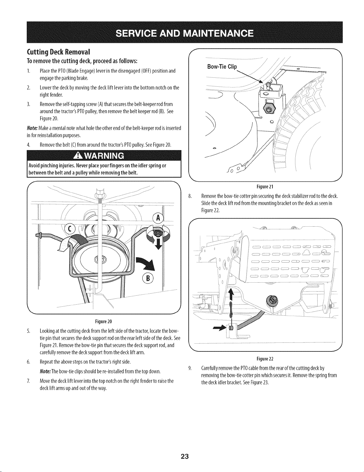
5. Lookingat the cuttingdeckfromthe left sideof thetractor,locatethebow-
tie pinthatsecuresthe decksupportrodon therearleft sideof thedeck.See
Figure21.Removethebow-tiepinthat securesthe decksupportrod,and
carefullyremovethe decksupportfromthe decklift arm.
6. Repeatthe abovestepsonthetractor'srightside.
Note:Thebow-tieclipsshouldbere-installedfromthetop down.
7. Movethedecklift leverintothetop notchon therightfenderto raisethe
decklift armsup andoutof theway.
Bow-TieClip
w
.J
Figure21
Removethe bow-tiecotter pinsecuringthedeckstabilizerrodto the deck.
Slidethe decklift rodfrom themounlng bracketonthe deckasseenin
Figure22.
.......,,_!_........ /_*_
iO
0
L
Zi_ 17_//;:3(7 :: CZ;iii ( :: (/) <i )<_Z'_)i::g>
_} ) ]) ZIZZ} ZIT) C} /£)) g Z>
J
Figure22
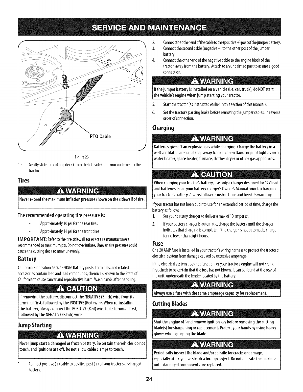
Carefullyremovethe PTOcablefromtherearof the cuttingdeckby
removingthe bow-tiecotterpin whichsecuresit. Removethespringfrom
thedeckidlerbracket.SeeFigure23.
23
/'
/
/
PTOCable
Figure23
10. Gentlyslidethecuttingdeck(fromthe left side)out from underneaththe
tractor.
Tires
Neverexceedthe maximum inflation pressureshownon the sidewall of tire.
Therecommendedoperating tire pressure is:
Approximately10psifor the reartires
Approximately14psiforthe front tires
[M PORTANT: Referto the tire sidewallfor exacttiremanufacturer's
recommendedor maximumpsi.Donotovednflate.Uneventire pressurecould
causethecuttingdeckto mowunevenly.
Battery
CaliforniaProposition65WARNING!Batteryposts,terminals,andrelated
accessoriescontainleadandleadcompounds,chemicalsknowntothe Stateof
Californiato causecancerandreproductiveharm.Washhandsafter handling.
If removing the battery, disconnectthe NEGATIVE(Black)wire from its
terminalfirst, followed bythe POSITIVE(Bed)wire. Whenre-installing
the battery, alwaysconnectthe POSITIVE(Bed)wire to itsterminal first,
[fo owedbythe NEGATME(Back)w re.
JumpStarting
Neverjump start a damagedorfrozen battery. Becertain the vehiclesdo not
touch,and ignitionsareoff. Donot allow cableclampsto touch.
Connectpositive(+)cableto positivepost(+) of yourtractor'sdischarged
battery.
2. Connecttheotherendofthecabletothe(positive+) postofthejumperbattery.
3. Connectthe secondcable(negative-) to the otherpostof thejumper
battery.
4. Connectthe otherendofthe negativecableto the engineblockofthe
tractor,awayfrom the battery.Attachto anunpaintedpartto assureagood
connection.
If the jumperbattery is installed on avehicle(i.e.car,truck),do NOTstart
the vehicle'senginewhenjump starting your tractor.
5. Startthe tractor(asinstructedearlierinthissectionof thismanual).
6. Setthetractor'sparkingbrakebeforeremovingthejumpercables,in reverse
orderofconnection.
Charging
Batteriesgiveoff anexplosivegaswhile charging. Chargethe battery in a
[wellventilated areaand keepawayfrom anopenflame or pilot light ason a
l water heater,spaceheater,furnace,clothesdryer or other gasappliances.
Whenchargingyourtractor'sbattery,useonly achargerdesignedfor 12Vlead-
acidbatteries.Readyourbatterycharger'sOwner'sManualpriorto charging
tourtractor's battery.Alwaysfollow itsinstructionsandheeditswarnings.
Ifyourtractorhasnotbeenputinto useforanextendedperiodoftime,chargethe
batteryasfollows:
1. Setyourbatterychargerto delivera maxof 10amperes.
2. Ifyourbatterychargerisautomatic,chargethe batteryuntilthecharger
indicatesthatchargingiscomplete.Ifthechargerisnotautomatic,charge
for nofewerthaneighthours.
Fuse
One20AMPfuseisinstalledinyourtractor'swiring harnessto protectthetractor's
electricalsystemfromdamagecausedbyexcessiveamperage.
Ifthe electricalsystemdoesnotfunction,or yourtractor'senginewill not crank,
first checkto becertainthat thefusehasnot blown.Itcanbefoundat therearof
theunit, underneaththefenderlocatedbythe battery.
Alwaysusea fusewith thesameamperagecapacityfor replacement.
Cutting Blades
Shutthe engineoff and removeignitionkeybefore removing the cutting
blade(s)for sharpeningor replacement.Protectyour handsby using heavy
gloveswhen graspingthe blade.
Periodicallyinspectthe bladeand/or spindlefor cracksor damage,
especiallyafter you've struckaforeign object. Donot operate the machine
until damagedcomponentsare replaced.
24
Toremovethe blades,proceedasfollows:
1. Removethedeckfrom beneaththe tractor,(referto CuttingDeckRemoval
earlierin thissection)thengentlyflip thedeckoverto exposeits underside.
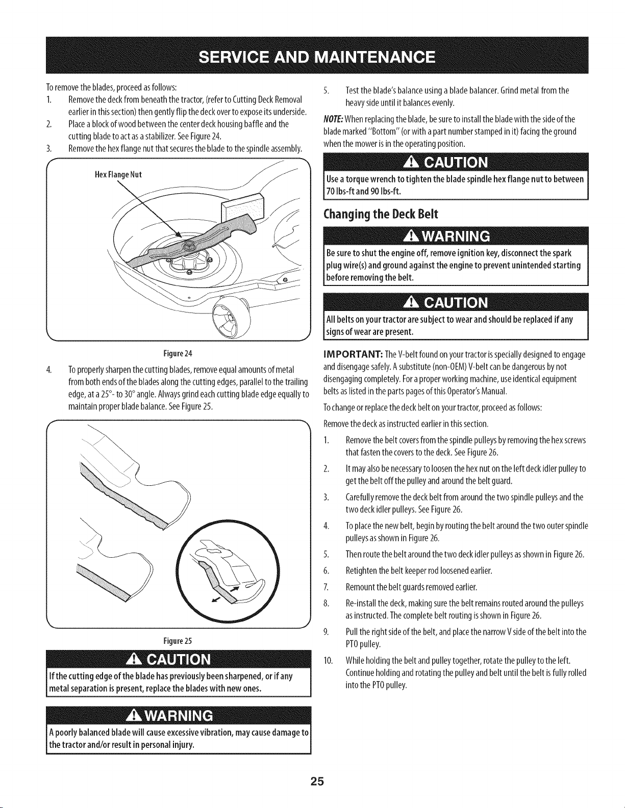
2. Placea blockofwoodbetweenthe centerdeckhousingbaffleandthe
cuttingbladeto actasastabilizer.SeeFigure24.
3. Removethehexflangenutthat securesthebladeto the spindleassembly.
F
HexFlangeNut
4.
Figure24
Toproperlysharpenthecutting blades,removeequalamountsof metal
from bothendsof thebladesalongthecuttingedges,parallelto the trailing
edge,ata 25°- to 30°angle.Alwaysgrindeachcuttingbladeedgeequallyto
maintainproperbladebalance.SeeFigure25.
Figure25
If the cutting edgeof theblade haspreviouslybeensharpened,or if any
metal separationispresent,replacethe bladeswith new ones.
5. Testthe blade'sbalanceusinga bladebalancer.Grindmetalfrom the
heavysideuntil it balancesevenly.
NOTE:Whenreplacingtheblade,besureto installthe bladewith the sideofthe
blademarked"Bottom" (orwith apartnumberstampedinit)facingtheground
whenthe mowerisintheoperatingposition.
Useatorque wrench to tighten the bladespindlehex flange nut to between
70 Ibs-ft and 90 Ibs-ft.
Changingthe DeckBelt
Besureto shutthe engineoff, removeignitionkey,disconnectthe spark
plugwire(s)and groundagainst the engineto prevent unintendedstarting
_beforeremovng the be t.
All belts on yourtractor aresubjectto wear andshouldbe replacedif any
signsof wear arepresent.
IM PORTANT: TheV-beltfoundon yourtractorisspeciallydesignedto engage
anddisengagesafely.Asubstitute(non-OEM)V-beltcanbedangerousbynot
disengagingcompletely.Foraproperworkingmachine,useidenticalequipment
beltsaslistedinthepartspagesof thisOperator'sManual.
Tochangeorreplacethedeckbelton yourtractor,proceedasfollows:
Removethedeckasinstructedearlierinthissection.
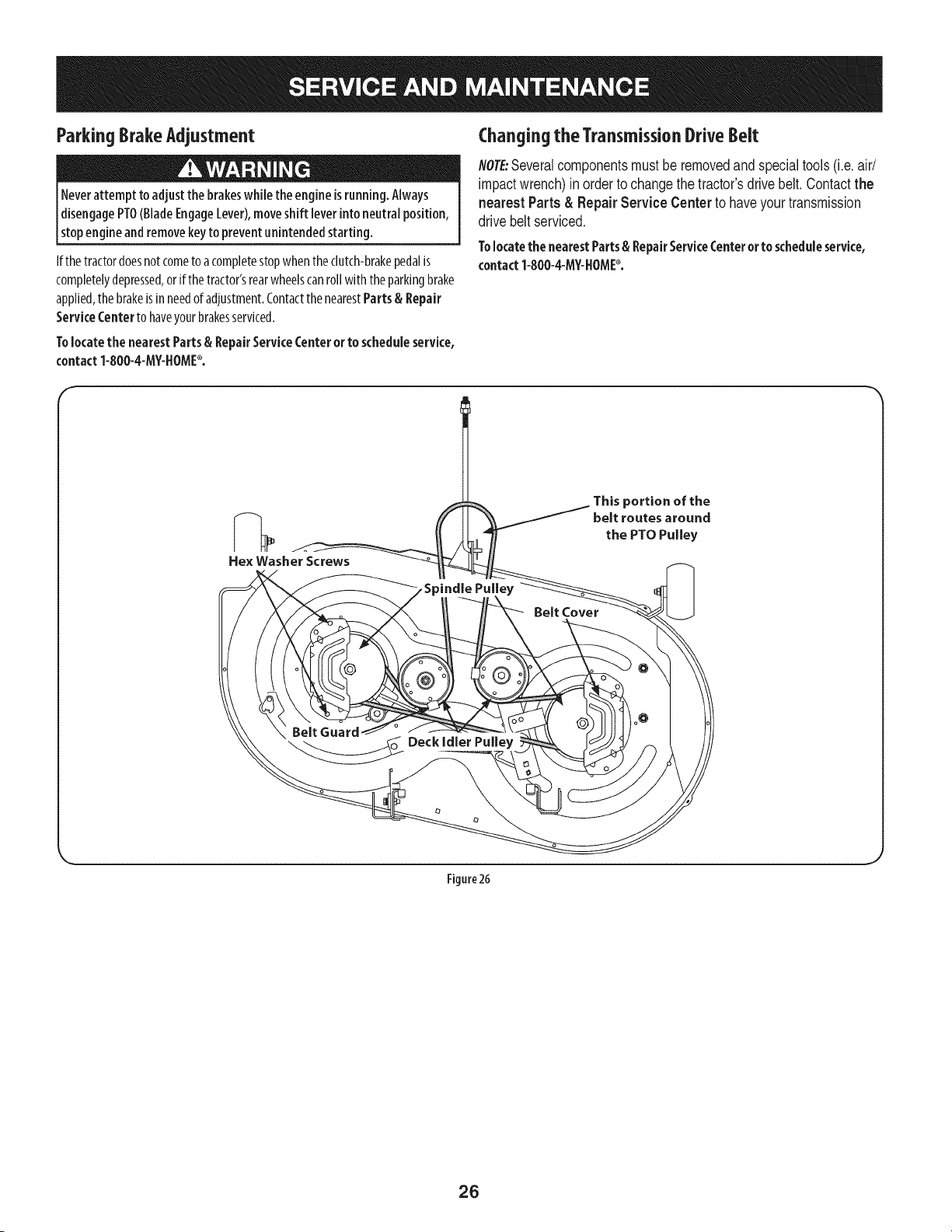
1. Removethebeltcoversfrom the spindlepulleysbyremovingthehexscrews
that fastenthecoverstothedeck.SeeFigure26.
2. It mayalsobe necessaryto loosenthe hexnut on the left deckidler pulleyto
getthe belt offthe pulleyandaroundthebeltguard.
3. Carefullyremovethe deckbelt fromaroundthetwo spindlepulleysandthe
two deckidlerpulleys.SeeFigure26.
4. Toplacethenewbelt,beginbyroutingthebelt aroundthetwo outerspindle
pulleysasshownin Figure26.
5. Thenroutethebelt aroundthetwo deckidlerpulleysasshownin Figure26.
6. Retightenthebeltkeeperrodloosenedearlier.
7. Remountthebelt guardsremovedearlier.
8. Re-installthedeck,makingsurethe belt remainsroutedaroundthepulleys
asinstructed.Thecompletebelt routingisshownin Figure26.
9. Pulltherightsideof the belt,andplacethenarrowVsideof thebelt into the
PTOpulley.
10. Whileholdingthe beltandpulleytogether,rotatethepulleyto theleft.
Continueholdingandrotatingthepulleyandbeltuntil the belt isfully rolled
into the PTOpulley.
Apoorly balancedbladewill causeexcessivevibration, may causedamageto
thetractor and/or result inpersonalinjury.
25
ParkingBrakeAdjustment
Neverattempt to adjust the brakeswhile theengine isrunning. AMays
disengagePTO(BladeEngageLever),moveshift leverinto neutral position,
stopengine andremovekeyto prevent unintendedstarting.
If the tractordoesnotcometo acompletestopwhentheclutch-brakepedalis
completelydepressed,or if thetractor'srearwheelscanrollwith theparkingbrake
applied,the brakeisinneedof adjustment.Contactthe nearestParts& Repair
ServiceCenterto haveyourbrakesserviced.
Tolocate the nearestParts& RepairServiceCenteror to schedule service,
contact1-800-4-MY-HOME_.
Changing the TransmissionDrive Belt
NO}E:Severalcomponentsmustbe removedand special tools(i.e. air/
impactwrench)inorderto changethetractor'sdrivebelt.Contactthe
nearest Parts & Repair Service Center to haveyour transmission
drive beltserviced.
Tolocatethe nearestParts& RepairServiceCenteror to scheduleservice,
contact1-800-4-MY-HOME_.
f
Hex Washer Screws
Belt Cover
_ortion of the
belt routes around
the PTO Pulley
Figure26
26
Neverstore lawn tractor with fuel intank indoorsor in poorlyventilated
areaswhere fuel fumes may reachan openflame, spark,or pilot light ason
afurnace,water heater,clothesdryer,or gasappliance.
PreparingTheEngine
IMPORTANT: Fuelleft inthefuel tankduringwarmweatherdeterioratesand
will causeseriousstartingproblems.
Topreventgumdepositsfromforminginsidethe engine'scarburetorandcausing
possiblemalfunctionoftheengine,the fuelsystemmustbeeithercompletely
emptied,orthe gasolinemustbetreatedwith astabilizerto preventdeterioration.
I. Ifusinga fuelstabilizer:
a. Readtheproductmanufacturer'sinstructionsandrecommendations.
b. Addto clean,freshgasolinethecorrectamountofstabilizerforthe
capacityof thefuel system.
c. Fillthefueltankwith treatedfuel andruntheenginefor 2-3minutesto
getstabilizedfuelinto thecarburetor.
2. Ifemptylngthefuelsystem:
a. Donotdrainfuelwhen theengineishot.Allowtheengineadequate
timeto cool.Drainfuel into anapprovedcontaineroutdoors,awayfrom
openflame.
b. Drainanylargevolumeof fuelfrom the tankbydisconnectingthe
fuel linefromthe in-linefuel filter neartheengine.Seethe complete
instructionsforDrainingTheFuellaterin thissection.
Gasolineisextremely flammable and canbe explosiveundercertain
conditions. Draingasolinebeforestoring theequipment for extended
periods.Drainfuel only into an approvedcontaineroutdoors,awayfrom
an open flame. Allow engine to cool.Extinguishcigarettes, cigars,pipes,
and other sourcesof ignitionprior to draining fuel. Storegasolineinan
approvedcontainerin safe location.
c. Reconnectthefuel lineandrunthe engineuntil it startsto falter,then
usethe choketo keepthe enginerunninguntilallfuel in thecarburetor
hasbeenexhausted.
d. Disconnectthe fuel lineanddrainanyremaininggasolinefrom the
system.
DrainingThe Fuel
1. Locatethe fuel filter,whichis locatedonthe left sideoftheengine,andmay
be attachedto theenginewitha tiestrap.
2. Cutthetie strap,if present,thenpinchthe in-lineclamponthefuel filter
with a pairof pliers,slidetheclampupthefuel line.
3. Pullthefuellinefreefromthe filterandplacetheopenendofthe lineinto
an approvedcontainerto drainthefuel.
PreparingThelawn tractor
Cleanandlubricatetractorthoroughlyasdescribedinthelubrication
instructions.
2. Donot usea pressurewasheror gardenhoseto cleanyourunit.
3. Storemowerin adry,cleanarea.Donotstorenextto corrosivematerials,
suchasfertilizer.
Gasolineisa toxicsubstance.Disposeof gasolineproperly.Contactyour
localauthorities for approveddisposalmethods.
3. Removethe sparkplugandpourone(1)ounceof engineoilthroughthespark
plugholeinto the cylinder.Cranktheengineseveraltimesto distributethe
oil. Replacethe sparkplug.
27
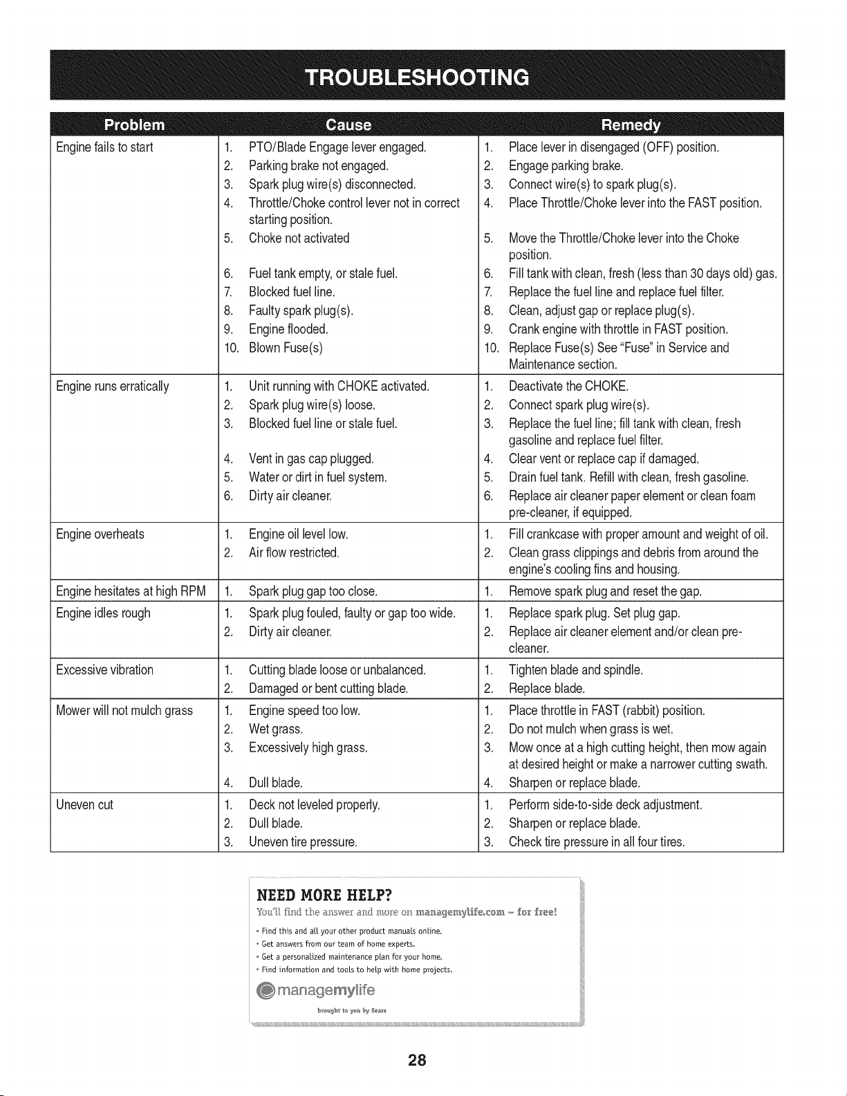
Enginefailsto start
Enginerunserratically
1. PTO/BladeEngageleverengaged.
2. Parkingbrakenotengaged.
3. Sparkplugwire(s)disconnected.
4. Throttle/Chokecontrollevernot incorrect
startingposition.
5. Chokenotactivated
6. Fueltankempty,or stalefuel.
7. BIockedfuel line.
8. Faultysparkplug(s).
9. Engineflooded.
10. BlownFuse(s)
1. Unit runningwith CHOKEactivated.
2. Sparkplugwire(s)loose.
3. Blockedfuel lineor stalefuel.
4. Ventingas cap plugged.
5. Wateror dirt infuel system.
6. Dirtyair cleaner.
Engineoverheats 1. Engineoillevellow. 1.
2. Air flow restricted. 2.
Enginehesitatesat highRPM 1. Sparkpluggaptoo close. 1.
Engineidles rough 1. Sparkplugfouled,faultyor gaptoo wide. 1.
2. Dirtyair cleaner. 2.
Excessivevibration
Mowerwill not mulchgrass
Unevencut
1. Cuttingbladelooseor unbalanced.
2. Damagedor bentcuttingblade.
1. Enginespeedtoo low.
2. Wetgrass.
3. Excessivelyhighgrass.
4. Dullblade.
1. Decknot leveledproperly.
2. Dullblade.
3. Uneventire pressure.
1. Placeleverindisengaged(OFF)position.
2. Engageparkingbrake.
3. Connectwire(s)to sparkplug(s).
4. PlaceThrottle/Chokeleverintothe FASTposition.
5. MovetheThrottle/Chokeleverintothe Choke
position.
6. Filltankwith clean,fresh (less than30 daysold) gas.
7. Replacethe fuel line and replacefuel filter.
8. Clean, adjustgap or replaceplug(s).
9. Crank enginewith throttlein FASTposition.
10. ReplaceFuse(s)See "Fuse"in Serviceand
Maintenancesection.
1. Deactivatethe CHOKE.
2. Connectsparkplugwire(s).
3. Replacethe fuel line;fill tank with clean,fresh
gasolineandreplacefuel filter.
4. Clear ventor replacecap if damaged.
5. Drainfuel tank. Refillwithclean,freshgasoline.
6. Replaceair cleanerpaperelementor cleanfoam
pre-cleaner,if equipped.
Fillcrankcasewith properamountand weightof oil.
Cleangrassclippingsanddebrisfrom aroundthe
engine'scoolingfinsandhousing.
Removesparkplug and resetthe gap.
Replacesparkplug.Set pluggap.
Replaceair cleanerelementand/orclean pre-
cleaner.
1. Tightenbladeand spindle.
2. Replaceblade.
1. Placethrottlein FAST(rabbit)position.
2. Do notmulchwhengrass is wet.
3. Mowonce at a highcuttingheight,then mowagain
at desiredheightor makea narrowercuttingswath.
4. Sharpenor replaceblade.
1. Performside-to-sidedeckadjustment.
2. Sharpenor replaceblade.
3. Checktire pressureinallfour tires.
NEED MORE HELP?
%£{_ls_lfim_} t}*_e_:_x/,',{'w(sran<I moze on manag<'_ly[i£eo{o_, - fo[ f_e÷!
Find this and a[[ your other product manuals online.
Get answers from our team of home experts.
Get a personalized maintenance plan for your home.
Find information and tools to help with home projects.
28
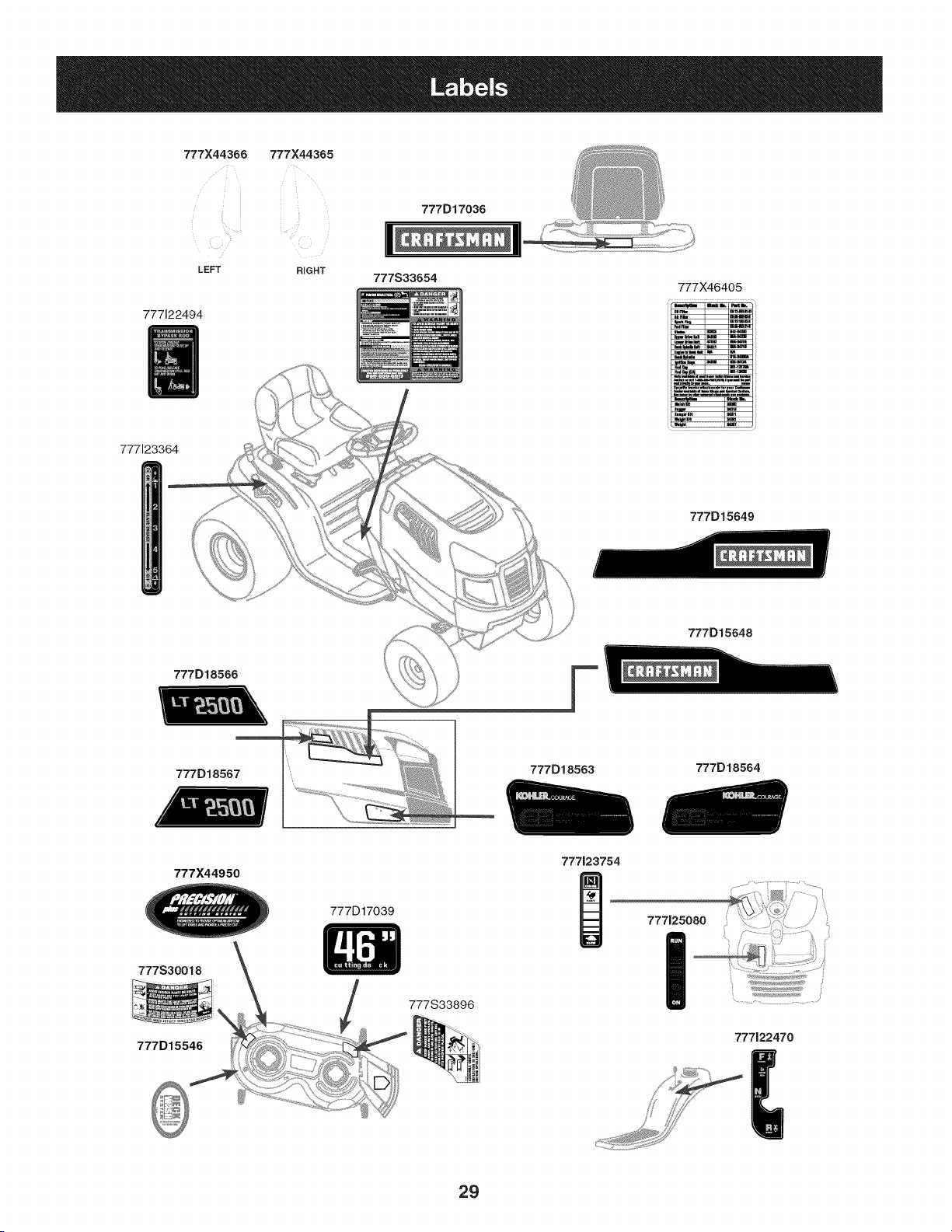
777X44366 777X44365
777122494
777D17036
t_
..... II
LEFT RIGHT
777S33654
777X46405
777123364
777D15649
777D15648
777D18566
777D18567
777D18563
777D18564
777X44950
777123754
777S30018
777D15546
777D17039
777S33896
777125080
I
777122470
29
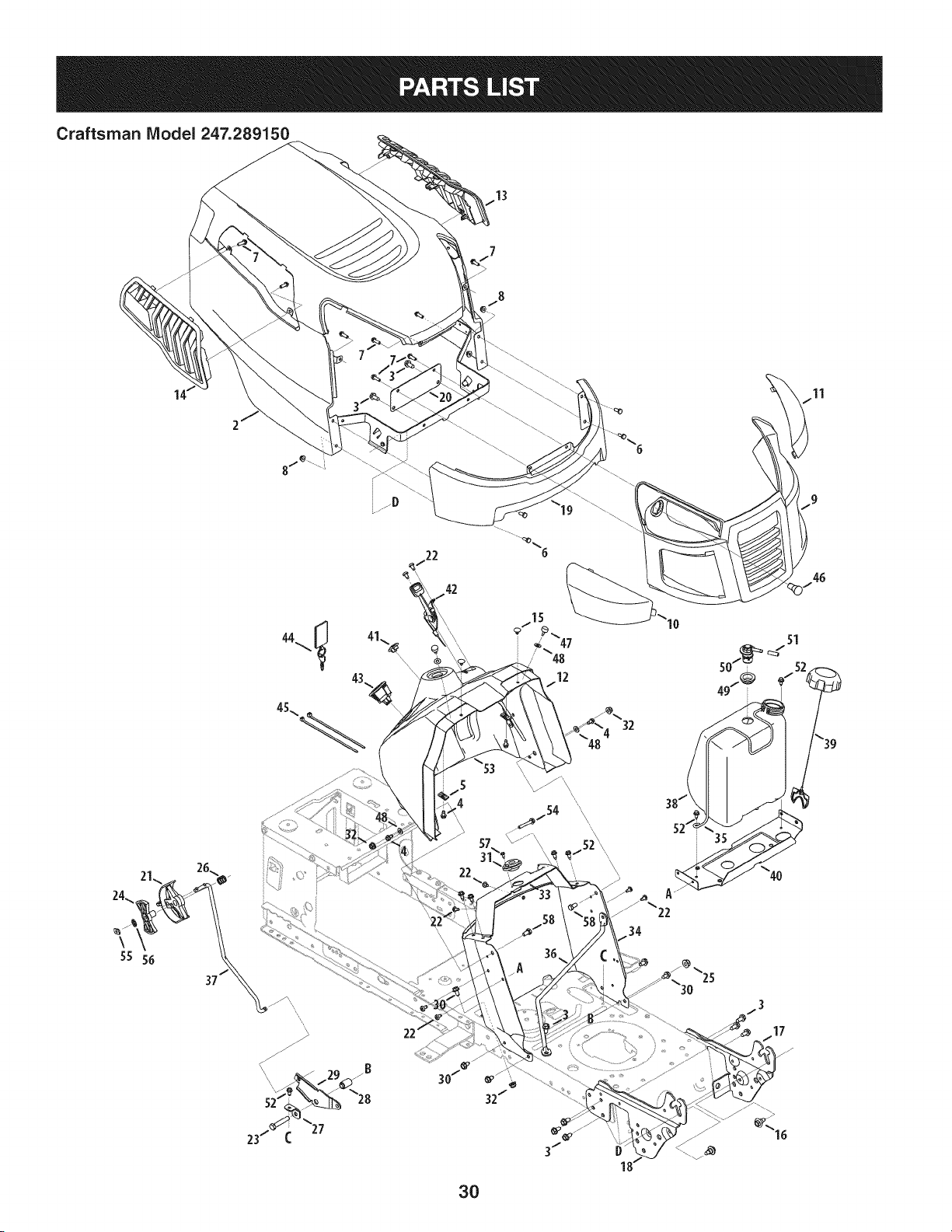
Craftsman Model 247.289150
11
\
55 56
37
42
31
22
3O
32
IO
46
35
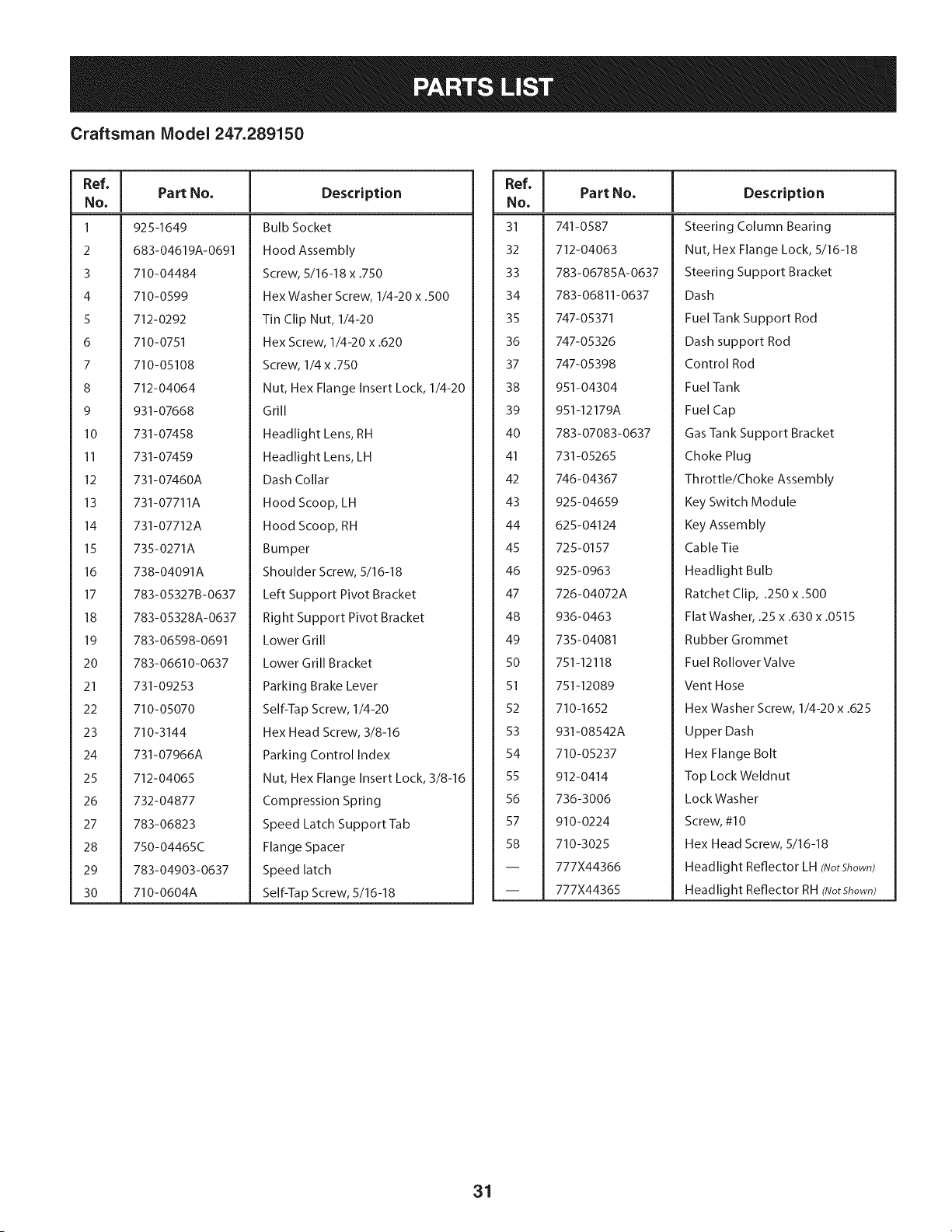
Craftsman Model 247.289150
Ref, I
No.
1 92 S-1649
2 683-04619A-0691
3 710-04484
4 710-0599
S 712-0292
6 710-0751
7 710-05108
8 712-04064
9 931-07668
lO 731-07458
II 731-07459
12 731-07460A
13 731-07711A
14 731-07712A
15 735-0271A
16 738-04091A
17 783-05327B-0637
18 783-05328A-0637
19 783-06598-0691
20 783-06610-0637
21 731-09253
22 710-05070
23 710-3144
24 731-07966A
25 712-04065
26 732-04877
27 783-06823
28 750-04465C
29 783-04903-0637
30 710-0604A
Part No. Description
Bulb Socket
Hood Assembly
Screw, 5/16-18 x .750
Hex Washer Screw, 1/4-20 x .500
Tin Clip Nut, 1/4-20
Hex Screw, 1/4-20 x .620
Screw, 1/4 x .750
Nut, Hex Flange Insert Lock, 1/4-20
Grill
Headlight Lens, RH
Headlight Lens, LH
Dash Collar
Hood Scoop, LH
Hood Scoop, RH
Bumper
Shoulder Screw, 5/16-18
Left Support Pivot Bracket
Right Support Pivot Bracket
Lower Grill
Lower Grill Bracket
Parking Brake Lever
Self-Tap Screw, 1/4-20
Hex Head Screw, 3/8-16
Parking Control Index
Nut, Hex Flange Insert Lock, 3/8-16
Compression Spring
Speed Latch Support Tab
Flange Spacer
Speed latch
Self-Ta p Screw, 5/16-18
Ref, I
No,
31 741-0587
32 712-04063
33 783-06785A-0637
34 783-06811-0637
35 747-05371
36 747-05326
37 747-05398
38 951-04304
39 951-12179A
40 783-07083-0637
41 731-05265
42 746-04367
43 925-04659
44 625-04124
45 725-0157
46 925-0963
47 726-04072A
48 936-0463
49 735-04081
50 751-12118
51 751-12089
52 710-1652
53 931-08542A
54 710-05237
55 912-0414
56 736-3006
57 910-0224
58 710-3025
-- 777X44366
-- 777X44365
Part No, Description
Steering Column Bearing
Nut, Hex Flange Lock, 5/16-18
Steering Support Bracket
Dash
Fuel Tank Support Rod
Dash support Rod
Control Rod
Fuel Tank
Fuel Cap
Gas Tank Support Bracket
Choke Plug
Throttle/Choke Assembly
Key Switch Module
Key Assembly
Cable Tie
Headlight Bulb
Ratchet Clip, .250 x .500
Flat Washer, .25 x .630 x .0515
Rubber Grommet
Fuel Rollover Valve
Vent Hose
Hex Washer Screw, 1/4-20 x .625
Upper Dash
Hex Flange Bolt
Top Lock Weldnut
LockWasher
Screw, #10
Hex Head Screw, 5/16-18
Headlight Reflector LH (NotShown)
Headlight Reflector RH (NotShown)
31
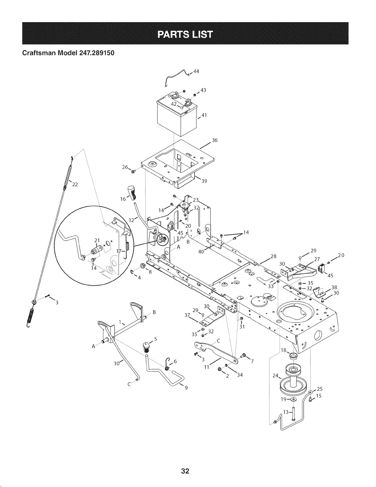
Craftsman Model 247.289150
.44
36
22
21
29
11
2 34
3O
32
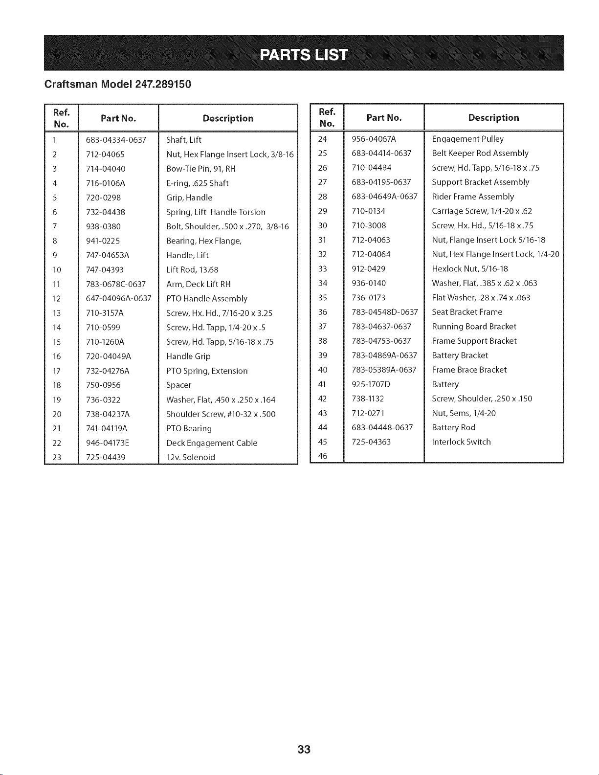
Craftsman Model 247.289150
Ref, ]
No,
1 683-04334-0637
2 712-04065
3 714-04040
4 716-0106A
5 720-0298
6 732-04438
7 938-0380
8 941-0225
9 747-04653A
10 747-04393
II 783-0678C-0637
12 647-04096A-0637
13 710-3157A
14 710-0599
15 710-1260A
16 720-04049A
17 732-04276A
18 750-0956
19 736-0322
20 738-04237A
21 741-04119A
22 946-04173E
23 725-04439
Part No, Description
Shaft, Lift
Nut, Hex Flange Insert Lock, 3/8-16
Bow-Tie Pin, 91, RH
E-ring, .625 Shaft
Grip, Handle
Spring, Lift Handle Torsion
Bolt, Shoulder, .500 x .270, 3/8-16
Bearing, Hex Flange,
Handle, Lift
Lift Rod, 13.68
Arm, Deck Lift RH
PTO Handle Assembly
Screw, Hx. Hd., 7/16-20 x 3.25
Screw, Hd. lapp, 1/4-20 x .5
Screw, Hd. lapp, 5/16-18 x .75
Handle Grip
PTO Spring, Extension
Spacer
Washer, Flat, .450 x .250 x .164
Shoulder Screw, #10-32 x .500
PTO Bearing
Deck Engagement Cable
12v. Solenoid
Ref, I
No,
24 956-04067A
25 683-04414-0637
26 710-04484
27 683-04195-0637
28 683-04649A-0637
29 710-0134
30 710-3008
31 712-04063
32 712-04064
33 912-0429
34 936-0140
35 736-0173
36 783-04548D-0637
37 783-04637-0637
38 783-04753-0637
39 783-04869A-0637
40 783-05389A-0637
41 925-1707D
42 738-1132
43 712-0271
44 683-04448-0637
45 725-04363
46
Part No, Description
Engagement Pulley
Belt Keeper Rod Assembly
Screw, Hd. lapp, 5/16-18 x .75
Support Bracket Assembly
Rider Frame Assembly
Carriage Screw, 1/4-20 x .62
Screw, Hx. Hd., 5/16-18 x .75
Nut, Flange Insert Lock 5/16-18
Nut, Hex Flange Insert Lock, 1/4-20
Hexlock Nut, 5/16-18
Washer, Flat, .385 x .62 x .063
Flat Washer, .28 x .74 x .063
Seat Bracket Frame
Running Board Bracket
Frame Support Bracket
Battery Bracket
Frame Brace Bracket
Battery
Screw, Shoulder, .250 x .150
Nut, Seres, 1/4-20
Battery Rod
Interlock Switch
33
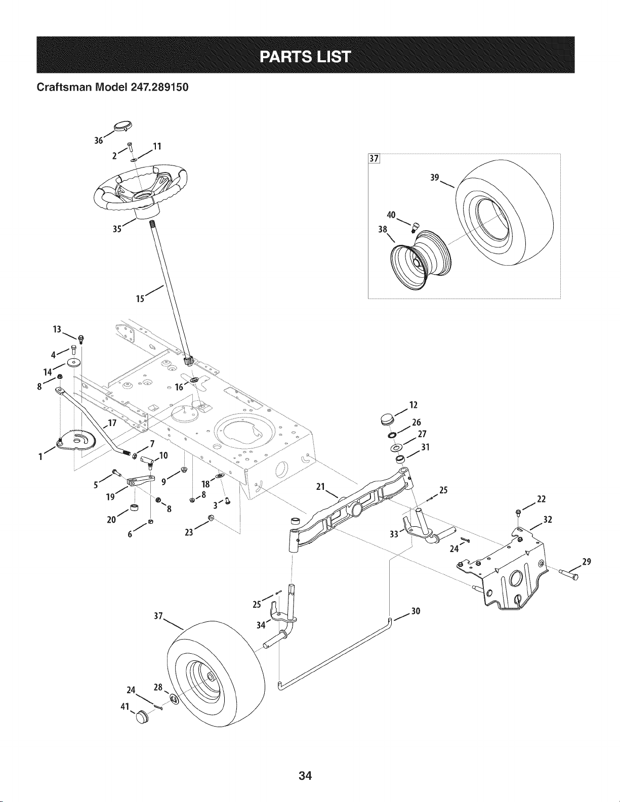
Craftsman IViodel 247.289150
39
4O
38
\
13
4j
12
QJ 26
o _ 27
_J31
25J
37_ 34._
_ __\\"-_ )
25
29
34
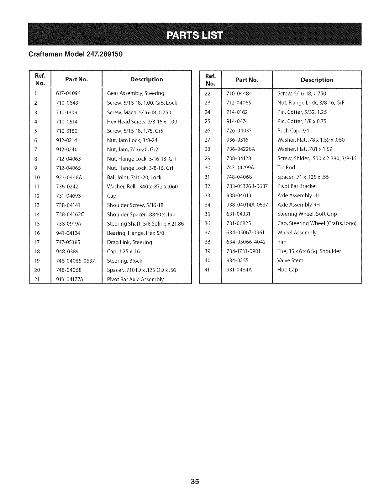
Craftsman Model 247.289150
Ref, I
No,
1 617-04094
2 710-0643
3 710-I 309
4 710-0514
5 710-3180
6 912-0214
7 912-0240
8 712-04063
9 712-04065
l 0 923-0448A
II 736-0242
12 731-04693
13 738-04141
14 738-04162C
15 738-0919A
16 941-04124
17 747- 05385
18 948-0389
19 748-04065-0637
20 748-04068
21 919-04177A
Part No. Description
Gear Assembly, Steering
Screw, 5/16-18, 1.00, GrS, Lock
Screw, Mach, 5/16-18, 0.750
Hex Head Screw, 3/8-16 x 1.00
Screw, 5/16-18, 1.75, Gr5
Nut, Jam Lock, 3/8-24
Nut, Jam, 7/16-20, Gr2
Nut, Flange Lock, 5/16-18, Grf
Nut, Flange Lock, 3/8-16, Grf
Ball Joint, 7/16-20, Lock
Washer, Bell, .340 x .872 x .060
Cap
Shoulder Screw, 5/16-18
Shoulder Spacer, .8840 x .190
Steering Shaft, 5/8 Spline x 21.86
Bearing, Flange, Hex 5/8
Drag Link, Steering
Cap, 1.25 x .16
Steering, Block
Spacer, .710 ID x .125 OD x .56
Pivot Bar Axle Assembly
Ref, I
No,
22 710-04484
23 712-04065
24 714-0162
25 914-0474
26 726-04035
27 936-0316
28 736-04228A
29 738-04128
30 747-04299A
31 748-04068
32 783-05326B-0637
33 938-04013
34 938-04014A-0637
35 631-04331
36 731-06825
37 634-05067-0961
38 634-05066-4042
39 734-1731-0901
40 934-0255
41 931-0484A
Part No, Description
Screw, 5/16-18, 0.750
Nut, Flange Lock, 3/8-16, GrF
Pin, Cotter, 5/32, 1.25
Pin, Cotter, 1/8 x 0.75
Push Cap, 3/4
Washer, Flat, .78 x 1.59 x .060
Washer, Flat, .781 x 1.59
Screw, Shlder, .500 x 2.380, 3/8-16
Tie Rod
Spacer, .71 x .125 x .56
Pivot Bar Bracket
Axle Assembly LH
Axle Assembly RH
Steering Wheel, Soft Grip
Cap, Steering Wheel (Crafts. logo)
Wheel Assembly
Rim
Tire, 15 x 6 x 6 Sq. Shoulder
Valve Stem
Hub Cap
35
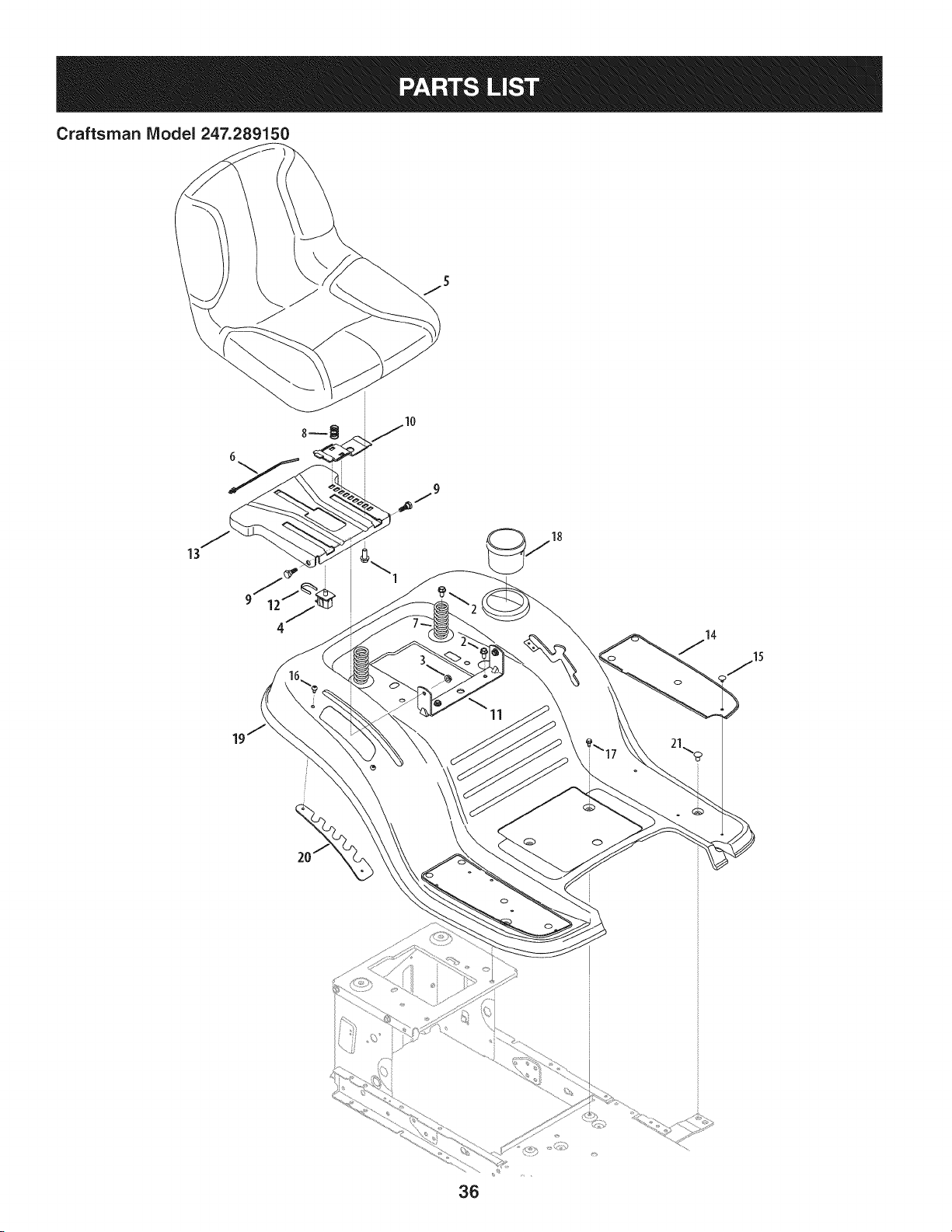
Craftsman Model 247.289150
13
\
11
36
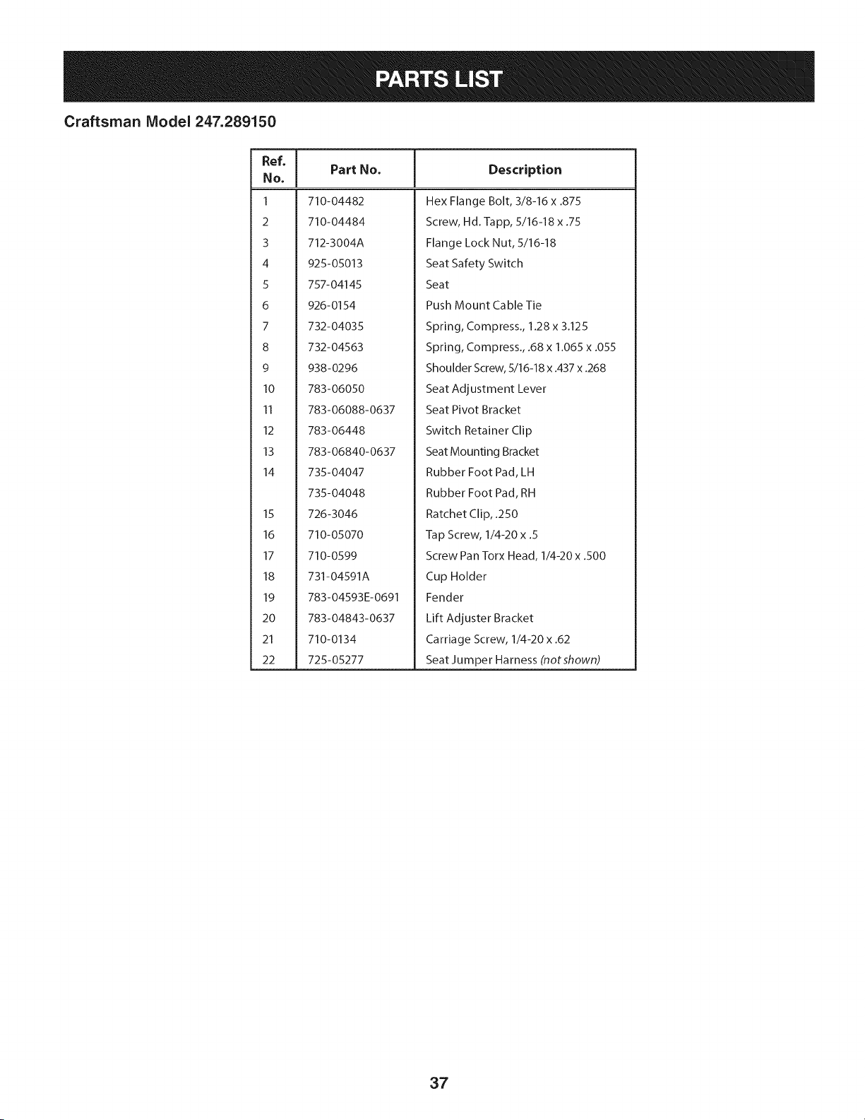
Craftsman Model 247.289150
Ref, [
No,
1 710-04482
2 710-04484
3 712-3004A
4 925-05013
5 757-04145
6 926-0154
7 732-04035
8 732-04563
9 938-0296
10 783-06050
II 783-06088-0637
12 783-06448
13 783-06840-0637
14 735-04047
735-04048
15 726-3046
16 710-05070
17 710-0599
18 731-04591A
19 783-04593E-0691
20 783-04843-0637
21 710-0134
22 725-05277
Part No. Description
Hex Flange Bolt, 3/8-16 x .875
Screw, Hd. lapp, 5/16-18 x .75
Flange Lock Nut, 5/16-18
Seat Safety Switch
Seat
Push Mount Cable Tie
Spring, Compress., 1.28 x 3.125
Spring, Compress., .68 x 1.065 x .055
Shoulder Screw, 5/16-18 x .437 x .268
Seat Adjustment Lever
Seat Pivot Bracket
Switch Retainer Clip
Seat Mounting Bracket
Rubber Foot Pad, LH
Rubber Foot Pad, RH
Ratchet Clip, .250
Tap Screw, 1/4-20 x .5
Screw Pan Torx Head, 1/4-20 x .500
Cup Holder
Fender
Lift Adjuster Bracket
Carriage Screw, 1/4-20 x .62
Seat Ju m per Ha mess (not shown)
37
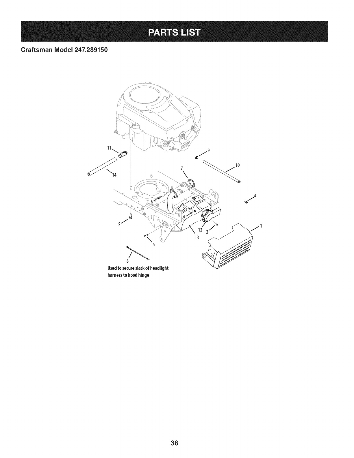
Craftsman IViodel 247.289150
7
gsedtosecureslackofheadlight
harnessto hoodhinge
j4
38
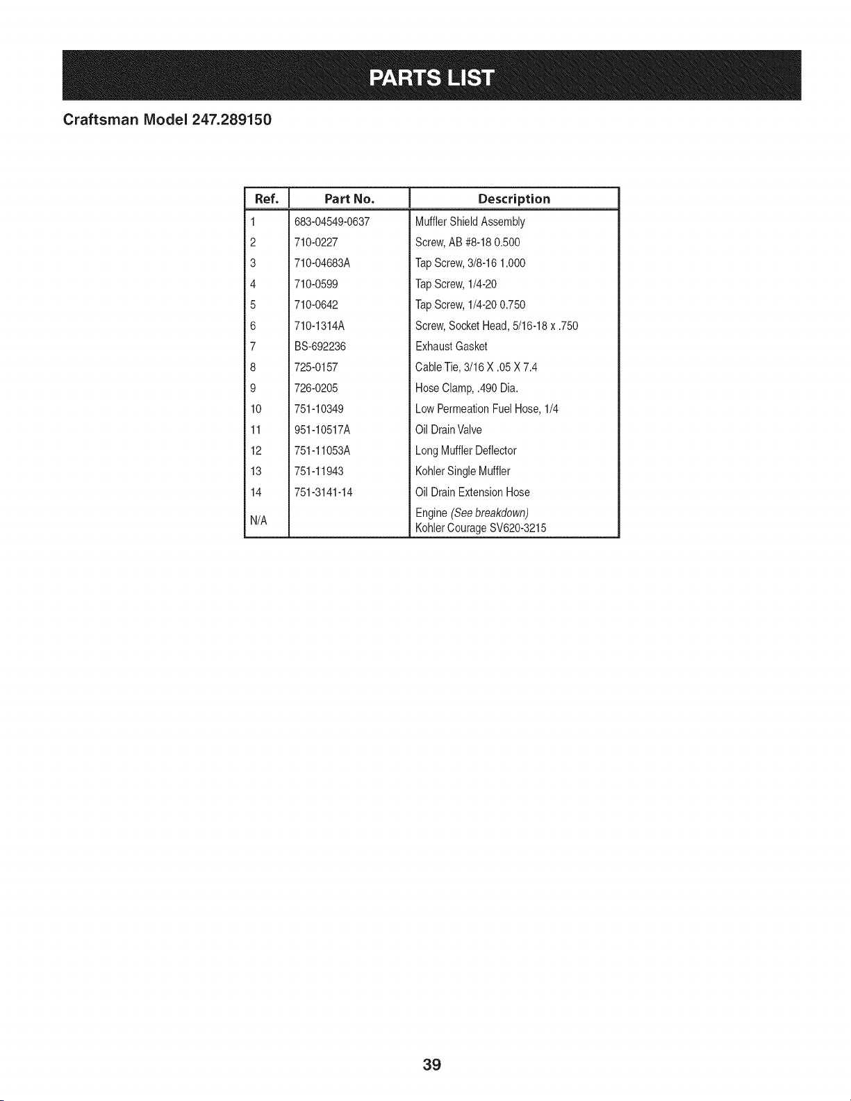
Craftsman IViodel 247.289150
I
Ref.
I Part No.
1 683-04549-0637
2 710-0227
3 710-04683A
4 710-0599
5 710-0642
6 710-1314A
7 BS-692236
8 725-0157
9 726-0205
10 751-10349
11 951-10517A
12 751-11053A
13 751-11943
14 751-3141-14
N/A
Description
MufflerShield Assembly
Screw,AB #8-180.500
TapScrew,3/8-16 1.000
TapScrew,1/4-20
TapScrew,1/4-200.750
Screw,SocketHead,5/16-18x .750
ExhaustGasket
CableTie,3/16 X .05 X 7.4
HoseClamp,.490 Dia.
LowPermeationFuelHose,1/4
Oil DrainValve
LongMufflerDeflector
KohlerSingleMuffler
Oil DrainExtensionHose
Engine(Seebreakdown)
KohlerCourageSV620-3215
39
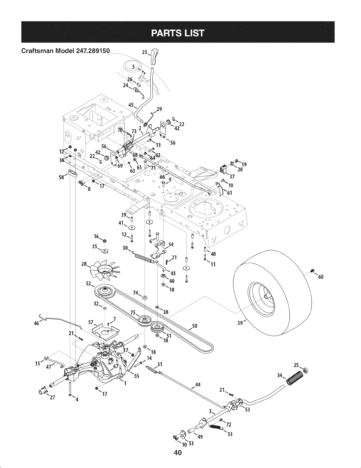
Craftsman Model 247.289150 23_
29
I_22
42
_13 _56
63
44
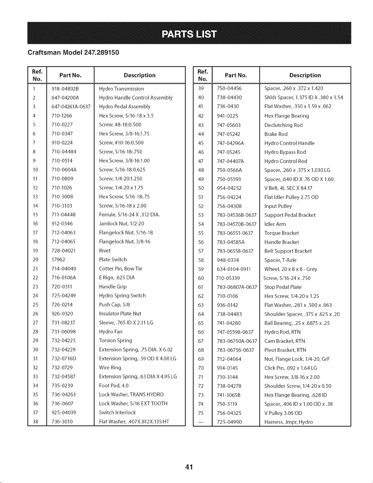
Craftsman Model 247.289150
Ref, [
No,
1 918-04892B
2 647-04200A
3 647-04261A-0637
4 710-1266
5 710-0227
6 710-0347
7 910-0224
8 710-04484
9 710-0514
10 710-0604A
II 710-0809
12 710-I026
13 710-3008
14 710-3103
15 711-04448
16 912-0346
17 712-04063
18 712-04065
19 728-04021
20 17962
21 714-04040
22 716-0106A
23 720-0311
24 725-04249
25 726-0214
26 926-0320
27 731-08237
28 731-06098
29 732-04225
30 732-04229
31 732-0716D
32 732-0729
33 732-04587
34 735-0239
35 736-04263
36 736-0607
37 925-04039
38 736-3010
Part No, Description
Hydro Transmission
Hydro Handle Control Assembly
Hydro Pedal Assembly
Hex Screw, 5/16-18 x 3.5
Screw, #8-18:0.500
Hex Screw, 3/8-16:1.75
Screw, #10-16:0.500
Screw, 5/16-18:.750
Hex Screw, 3/8-16:1.00
Screw, 5/16-18:0.625
Screw, 1/4-20:1.250
Screw, 1/4-20 x 1.75
Hex Screw, 5/16-18:.75
Screw, 5/16-18 x 2.00
Ferrule, 5/16-24 X .312 DIA.
Jamlock Nut, 1/2-20
Flangelock Nut, 5/16-18
Flangelock Nut, 3/8-16
Rivet
Plate Switch
Cotter Pin, Bow Tie
E Rign, .625 DIA
Handle Grip
Hydro Spring Switch
Push Cap, 5/8
Insulator Plate Nut
Sleeve, .765 ID X2.11 LG
Hydro Fan
Torsion Spring
Extension Spring, .75 DIA. X 6.02
Extension Spring, .59 OD X 4.00 LG
Wire Ring
Extension Spring, .63 DIA X 4.95 LG
Foot Pad, 4.0
Lock Washer, TRANS HYDRO
Lock Washer, 5/16 EXT TOOTH
Switch Interlock
Flat Washer, .407X.812X.135:HT
Ref, [
No,
39 750-04456
40 738-04430
41 736-0430
42 941-0225
43 747-05603
44 747-05242
45 747-04296A
46 747-05245
47 747-04407A
48 750-0566A
49 750-05593
50 954-04252
51 756-04224
52 756-04308
53 783-04536B-0637
54 783-04570B-0637
55 783-06551-0637
56 783-04585A
57 783-06558-0637
58 948-0334
59 634-0104-0911
60 710-05339
61 783-06807A-0637
62 710-0106
63 936-0142
64 738-04483
65 741-04280
66 747-05598-0637
67 783-06750A-0637
68 783-06756-0637
69 712-04064
70 914-0145
71 710-3144
72 738-04278
73 741-3065B
74 750-3119
75 756-04325
-- 725-04990
Part No, Description
Spacer, .260 x .372 x 1.420
Shldr Spacer, 1.375 ID X .380x 1.54
Flat Washer, .350 x 1.59 x .062
Hex Flange Bearing
Declutching Rod
Brake Rod
Hydro Control Handle
Hydro Bypass Rod
Hydro Control Rod
Spacer, .260 x .375 x 1.030 LG
Spacer, .640 ID X .76 OD X 1.60
V Belt, 4L SEC X 84.17
Flat Idler Pulley 2.75 OD
Input Pulley
Support Pedal Bracket
Idler Arm
Torque Bracket
Handle Bracket
Belt Support Bracket
Spacer, T-Axle
Wheel, 20 x 8 x 8 - Grey
Screw, 5/16-24 x .750
Stop Pedal Plate
Hex Screw, 1/4-20 x 1.25
Flat Washer, .281 x .500 x .063
Shoulder Spacer, .375 x .625 x .20
Ball Bearing, .25 x .6875 x .25
Hydro Rod, RTN
Cam Bracket, RTN
Pivot Bracket, RTN
Nut, Flange Lock, 1/4-20, GrF
Click Pin, .092 x 1.64 LG
Hex Screw, 3/8-16 x 2.00
Shoulder Screw, 1/4-20 x 0.50
Hex Flange Bearing, .628 ID
Spacer, .406 ID x 1.00 OD x .38
V Pulley 3.06 OD
Harness, Jmpr, Hydro
41
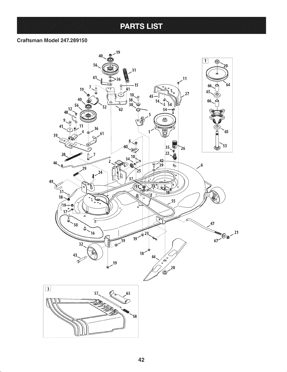
Craftsman Model 247.289150
27
19
@/
sL. _ 63 ss
42
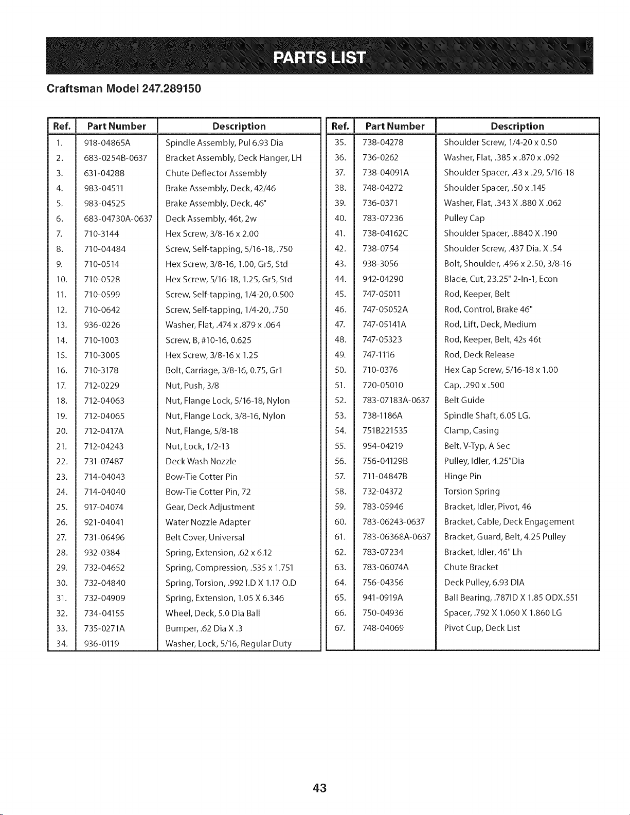
Craftsman Model 247.289150
Ref, I Part Number
1. 918-04865A
2. 683-0254B-0637
3. 631-04288
4. 983-04511
5. 983-04525
6. 683-04730A-0637
7. 710-3144
8. 710-04484
9. 710-0514
10. 710-0528
11. 710-0599
12. 710-0642
13. 936-0226
14. 710-1003
15. 710-3005
16. 710-3178
1Z 712-0229
18. 712-04063
19. 712-04065
20. 712-0417A
21. 712-04243
22. 731-07487
23. 714-04043
24. 714-04040
25. 917-04074
26. 921-04041
27. 731-06496
28. 932-0384
29. 732-04652
30. 732-04840
31. 732-04909
32. 734-04155
33. 735-0271A
34. 936-0119
Description
Spindle Assembly, Pul 6.93 Dia
Bracket Assembly, Deck Hanger, LH
Chute Deflector Assembly
Brake Assembly, Deck, 42/46
Brake Assembly, Deck, 46"
Deck Assembly, 46t, 2w
Hex Screw, 3/8-16 x 2.00
Screw, Self-tapping, 5/16-18, .750
Hex Screw, 3/8-16, 1.00, Gr5, Std
Hex Screw, 5/16-18, 1.25, Gr5, Std
Screw, Self-tapping, 1/4-20, 0.500
Screw, Self-tapping, 1/4-20, .750
Washer, Flat, .474 x .879 x .064
Screw, B, #10-16, 0.625
Hex Screw, 3/8-16 x 1.25
Bolt, Carriage, 3/8-16, 0.75, Grl
Nut, Push, 3/8
Nut, Flange Lock, 5/16-18, Nylon
Nut, Flange Lock, 3/8-16, Nylon
Nut, Flange, 5/8-18
Nut, Lock, 1/2-13
Deck Wash Nozzle
Bow-Tie Cotter Pin
Bow-Tie Cotter Pin, 72
Gear, Deck Adjustment
Water Nozzle Adapter
Belt Cover, Universal
Spring, Extension, .62 x 6.12
Spring, Compression, .535 x 1.751
Spring, Torsion, .992 I.D X 1.17 O.D
Spring, Extension, 1.05 X 6.346
Wheel, Deck, 5.0 Dia Ball
Bumper, .62 Dia X .3
Washer, Lock, 5/16, Regular Duty
Ref, I Part Number
35. 738-04278
36. 736-0262
37. 738-04091A
38. 748-04272
39. 736-0371
40. 783-07236
41. 738-04162C
42. 738-0754
43. 938-3056
44. 942-04290
45. 747-05011
46. 747-05052A
47. 747-05141A
Description
Shoulder Screw, 1/4-20 x 0.50
Washer, Flat, .385 x .870 x .092
Shoulder Spacer, .43 x .29, 5/16-18
Shoulder Spacer, .50 x .145
Washer, Flat, .343 X .880 X .062
Pulley Cap
Shoulder Spacer, .8840 X .190
Shoulder Screw, .437 Dia. X .54
Bolt, Shoulder, .496 x 2.50, 3/8-16
Blade, Cut, 23.25" 2-1n-1, Econ
Rod, Keeper, Belt
Rod, Control, Brake 46"
Rod, Lift, Deck, Medium
48. 747-05323
49. 747-1116
50. 710-0376
51. 720-05010
Rod, Keeper, Belt, 42s 46t
Rod, Deck Release
Hex Cap Screw, 5/16-18 x 1.00
Cap,.290 x .500
52. 783-07183A-0637
53. 738-1186A
54. 751B221535
55. 954-04219
56. 756-04129B
5Z 711-04847B
58. 732-04372
59. 783-05946
60. 783-06243-0637
61. 783-06368A-0637
62. 783-07234
63. 783-06074A
64. 756-04356
65. 941-0919A
66. 750-04936
67. 748-04069
Belt Guide
Spindle Shaft, 6.05 LG.
Clamp, Casing
Belt, V-Typ, A Sec
Pulley, Idler, 4.25"Dia
Hinge Pin
Torsion Spring
Bracket, Idler, Pivot, 46
Bracket, Cable, Deck Engagement
Bracket, Guard, Belt, 4.25 Pulley
Bracket, Idler, 46" Lh
Chute Bracket
Deck Pulley, 6.93 DIA
Ball Bearing, .7871D X 1.85 ODX.551
Spacer, .792 X 1.060 X 1.860 LG
Pivot Cup, Deck List
43
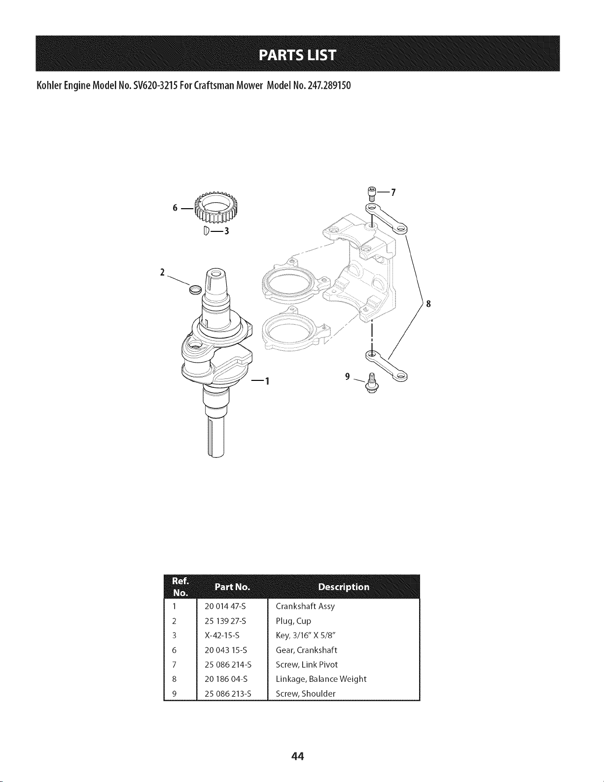
Kohler EngineModel No.SV620-3215For CraftsmanMower Model No. 247.289150
m
N
u
I
2
3
6
7
8
9
m
20 014 47-S
25 139 27-S
X-42-15-S
20 043 15-S
25 086 214-S
20 186 04-S
25 086 213-S
Crankshaft Assy
Plug, Cup
Key, 3/16" X 5/8"
Gear, Crankshaft
Screw, Link Pivot
Linkage, Balance Weight
Screw, Shoulder
44
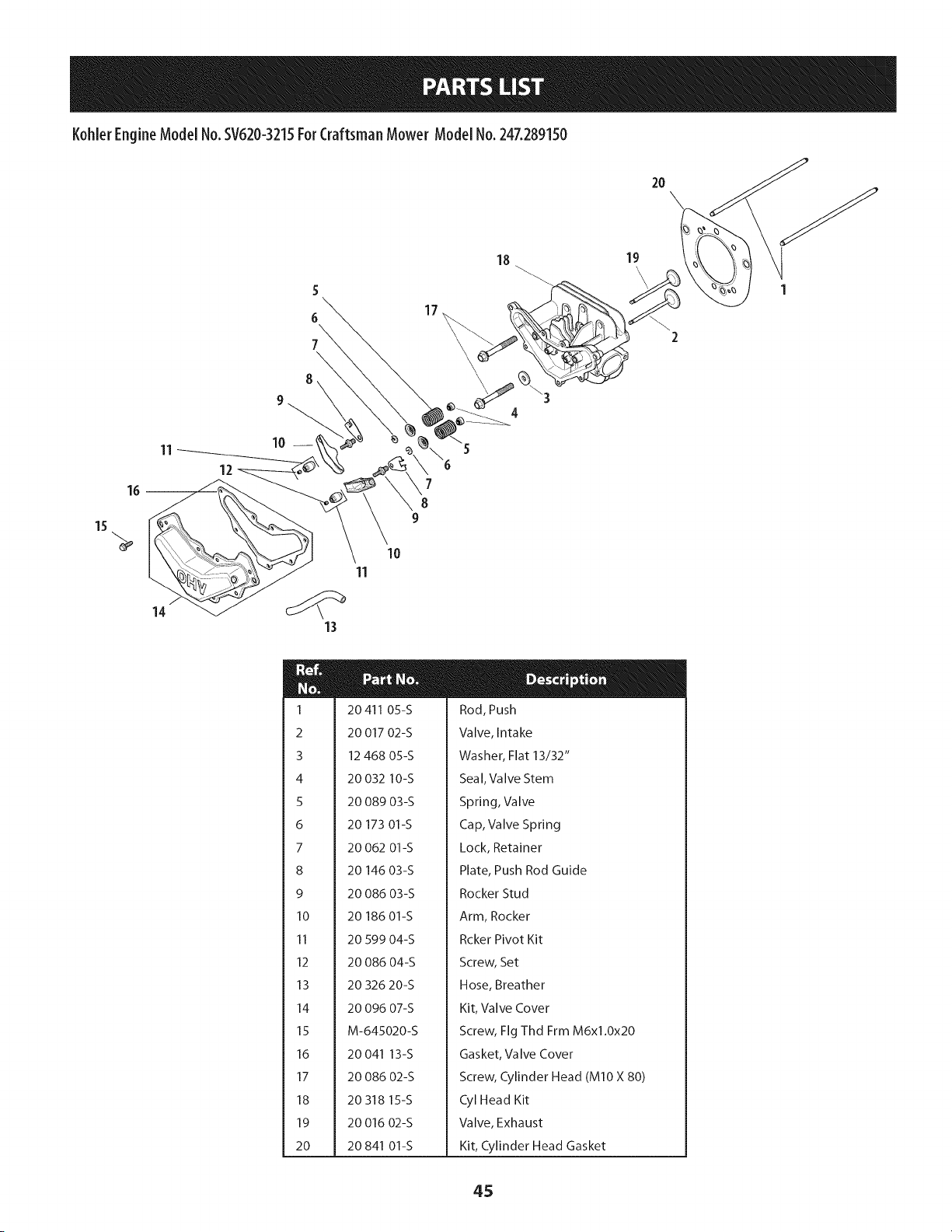
KohlerEngineModelNo.SV620-3215ForCraftsmanMowerModelNo.247.289150
15
11
14
12
8
9
20
17
18 19
\
4
7
8
9
1o
11
m
20411 05-S
20 017 02-S
12 468 05-S
20 032 10-S
20 089 03-S
20 173 01-S
20 062 01-S
20 146 03-S
20 086 03-S
20 186 01-S
20 599 04-S
20 086 04-S
20 326 20-S
20 096 07-S
M-645020-S
20 041 13-S
20 086 02-S
20 318 15-S
20 016 02-S
20 841 01-S
Rod, Push
Valve, Intake
Washer, Flat 13/32"
Seal, Valve Stem
Spring, Valve
Cap, Valve Spring
Lock, Retainer
Plate, Push Rod Guide
Rocker Stud
Arm, Rocker
Rcker Pivot Kit
Screw, Set
Hose, Breather
Kit, Valve Cover
Screw, Fig Thd Frm M6xl.0x20
Gasket, Valve Cover
Screw, Cylinder Head (MIO X 80)
Cyl Head Kit
Valve, Exhaust
Kit, Cylinder Head Gasket
45
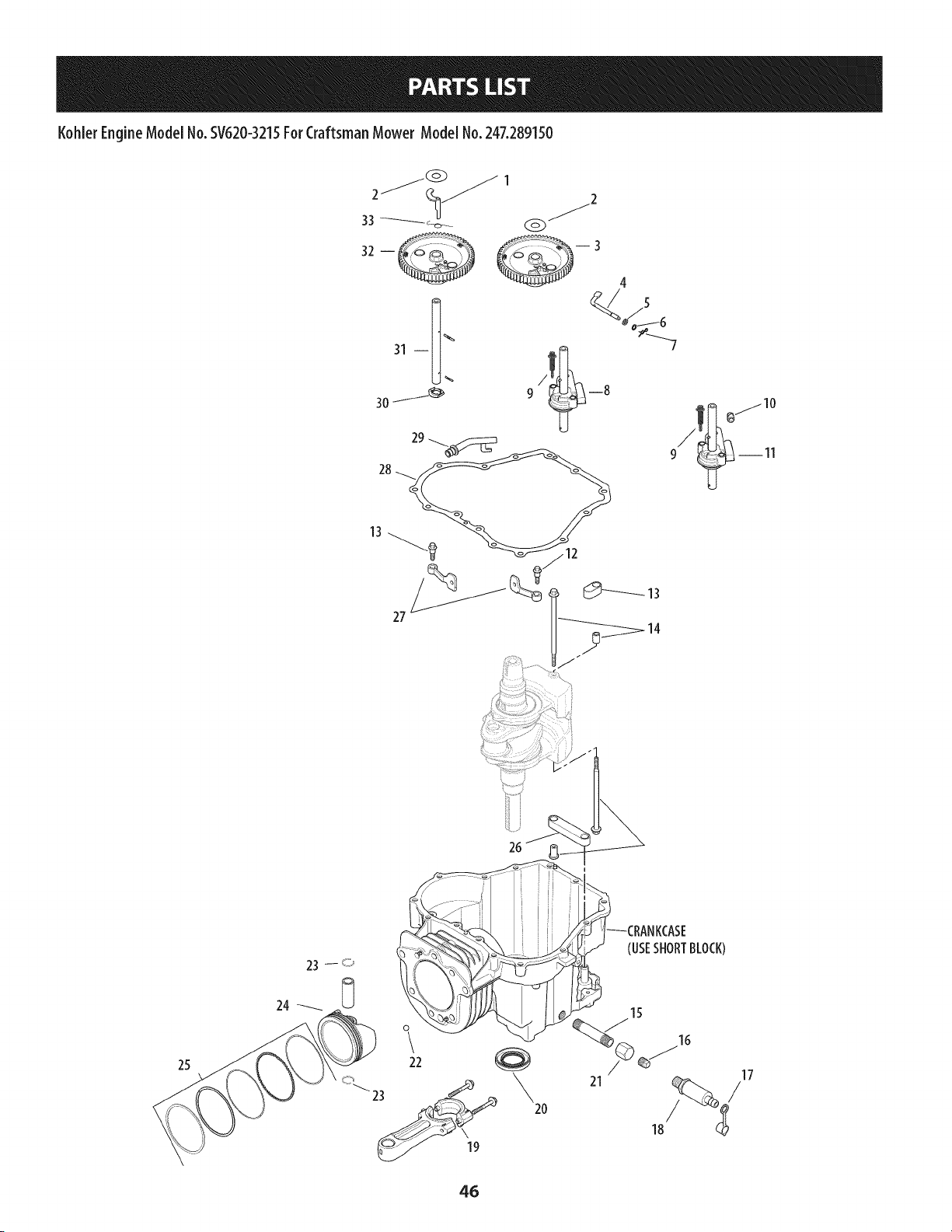
KohlerEngineModelNo.SV620-3215ForCraftsmanMower Model No.247.289150
2___ 1 _2
33 _- _-_ _-
4
23 -- o
24 _
0
\
22
\
2O
21
/
18
17
/
46
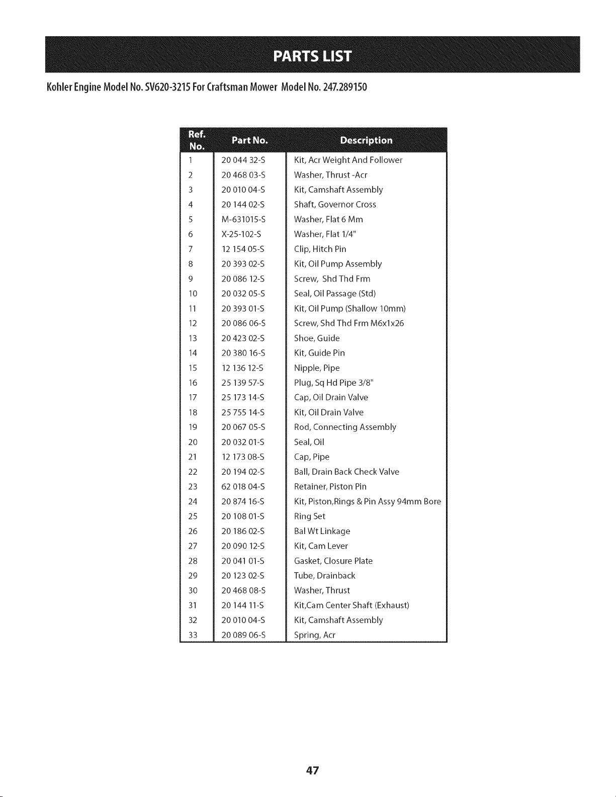
Kohler EngineModel No.SV620-3215ForCraftsman Mower Model No.247.289150
m
M
1
2
3
4
5
6
7
8
9
10
11
12
13
14
15
16
17
18
19
20
21
22
23
24
25
26
27
28
29
3O
31
32
33
20 044 32-S
20 468 03-S
20 010 04-S
20 144 02-S
M-631015-S
X-25-102-S
12 154 05-S
20 393 02-S
20 086 12-S
20 032 05-S
20 393 01-S
20 086 06-S
20 423 02-S
20 380 16-S
12 136 12-S
25 139 57-S
25 173 14-S
25 755 14-S
20 067 05-S
20 032 01-S
12 173 08-S
20 194 02-S
62 018 04-S
20 874 16-S
20 108 01-S
20 186 02-S
20 090 12-S
20 041 01-S
20 123 02-S
20 468 08-S
20 144 11-S
20 010 04-S
20 089 06-S
Kit, Acr Weight And Follower
Washer, Thrust -Acr
Kit, Camshaft Assembly
Shaft, Governor Cross
Washer, Flat 6 Mm
Washer, Flat 1/4"
Clip, Hitch Pin
Kit, Oil Pump Assembly
Screw, Shd Thd Frm
Seal, Oil Passage (Std)
Kit, Oil Pump (Shallow lOmm)
Screw, Shd Thd Frm M6xlx26
Shoe, Guide
Kit, Guide Pin
Nipple, Pipe
Plug, Sq Hd Pipe 3/8"
Cap, Oil Drain Valve
Kit, Oil Drain Valve
Rod, Connecting Assembly
Seal, Oil
Cap, Pipe
Ball, Drain Back Check Valve
Retainer, Piston Pin
Kit, Piston,Rings & Pin Assy 94mm Bore
Ring Set
Bal Wt Linkage
Kit, Cam Lever
Gasket, Closure Plate
Tube, Drainback
Washer, Thrust
Kit,Cam Center Shaft (Exhaust)
Kit, Camshaft Assembly
Spring, Act
47
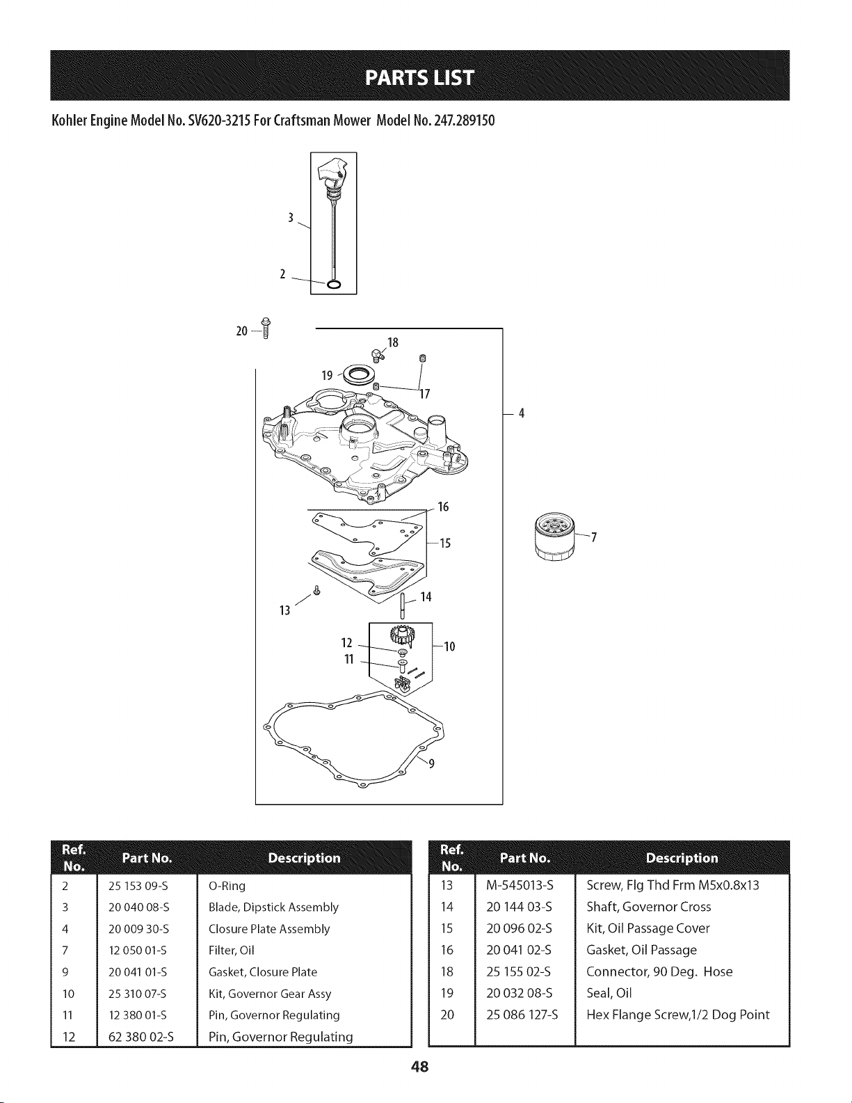
KohlerEngineModelNo.SV620-3215ForCraftsmanMower Model No.247.289150
3
2
204
13
18
12
11
-4
m
M
2
3
4
7
9
10
11
12
25 153 09-S
20 040 08-S
20 009 30-S
12 050 01-S
20 041 01-S
25 310 07-S
12 380 01-S
62 380 02-S
O-Ring
Blade, Dipstick Assembly
Closure Plate Assembly
Filter, Oil
Gasket, Closure Plate
Kit, Governor Gear Assy
Pin, Governor Regulating
Pin, Governor Regulating
m
M
u
13
14
15
16
18
19
20
48
M-545013-S
20 144 03-S
20 096 02-S
20 041 02-S
25 155 02-S
20 032 08-S
25 086 127-S
Screw, Fig Thd Frm M5x0.8x13
Shaft, Governor Cross
Kit, Oil Passage Cover
Gasket, Oil Passage
Connector, 90 Deg. Hose
Seal, Oil
Hex Flange Screw, I/2 Dog Point
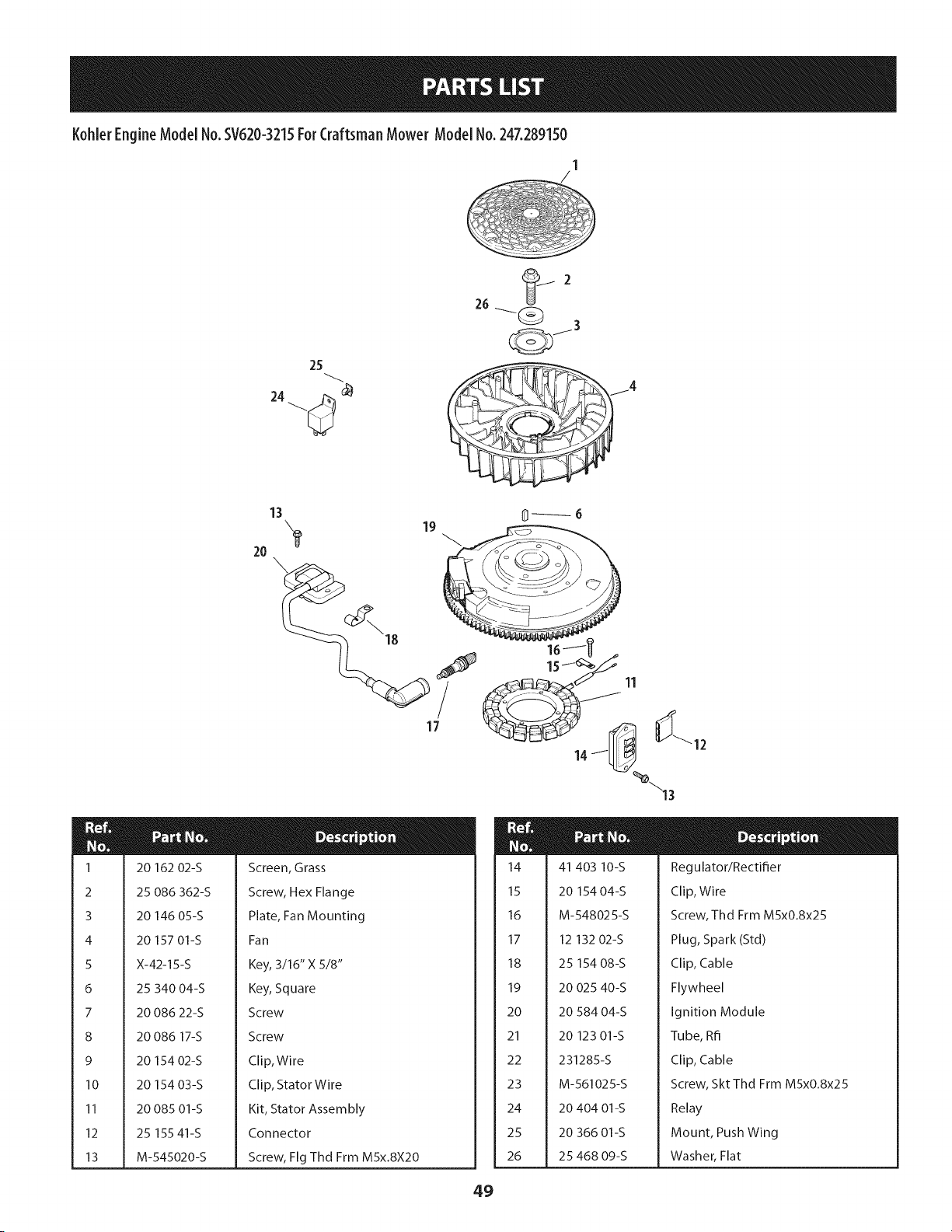
Kohler EngineModel No.SV620-3215ForCraftsman Mower Model No.247.289150
26
25
24 _
_J2
m
m
1
2
3
4
5
6
7
8
9
10
11
12
13
13
20
0_6
Screen, Grass
Screw, Hex Flange
Plate, Fan Mounting
Fan
Key, 3/16" X 5/8"
Key, Square
Screw
Screw
Clip, Wire
Clip, Stator Wire
Kit, Stator Assembly
Connector
Screw, Fig Thd Frm MSx.8X20
20 162 02-S
25 086 362-S
20 146 05-S
20 157 01-S
X-42-15-S
25 340 04-S
20 086 22-S
20 086 17-S
20 154 02-S
20 154 03-S
20 085 01-S
25 155 41-S
M-545020-S
m
14
15
16
17
18
19
20
21
22
23
24
25
26
m
41 403 10-S
20 154 04-S
M-548025-S
Regulator/Rectifier
Clip, Wire
Screw, Thd Frm MSxO.8x25
12 132 02-S
25 154 08-S
20 025 40-S
20 584 04-S
20 123 01-S
231285-S
M-561025-S
20 404 01-S
20 366 01-S
25 468 09-S
Plug, Spark (Std)
Clip, Cable
Flywheel
Ignition Module
Tube, Rfi
Clip, Cable
Screw, SktThd Frm MSxO.8x25
Relay
Mount, Push Wing
Washer, Flat
49
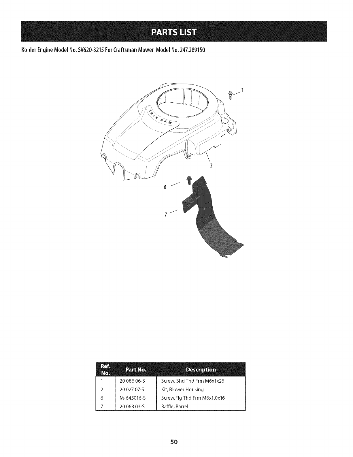
KohlerEngineModelNo.SV620-3215ForCraftsmanMower Model No.247.289150
J
6
J
7 _
mM
1 20 086 06-S Screw, Shd Thd Frm M6xlx26
2 20 027 07-S Kit, Blower Housing
6 M-645016-S Screw, Fig Thd Frm M6xl.0x16
7 20 063 03-S Baffle, Barrel
SO
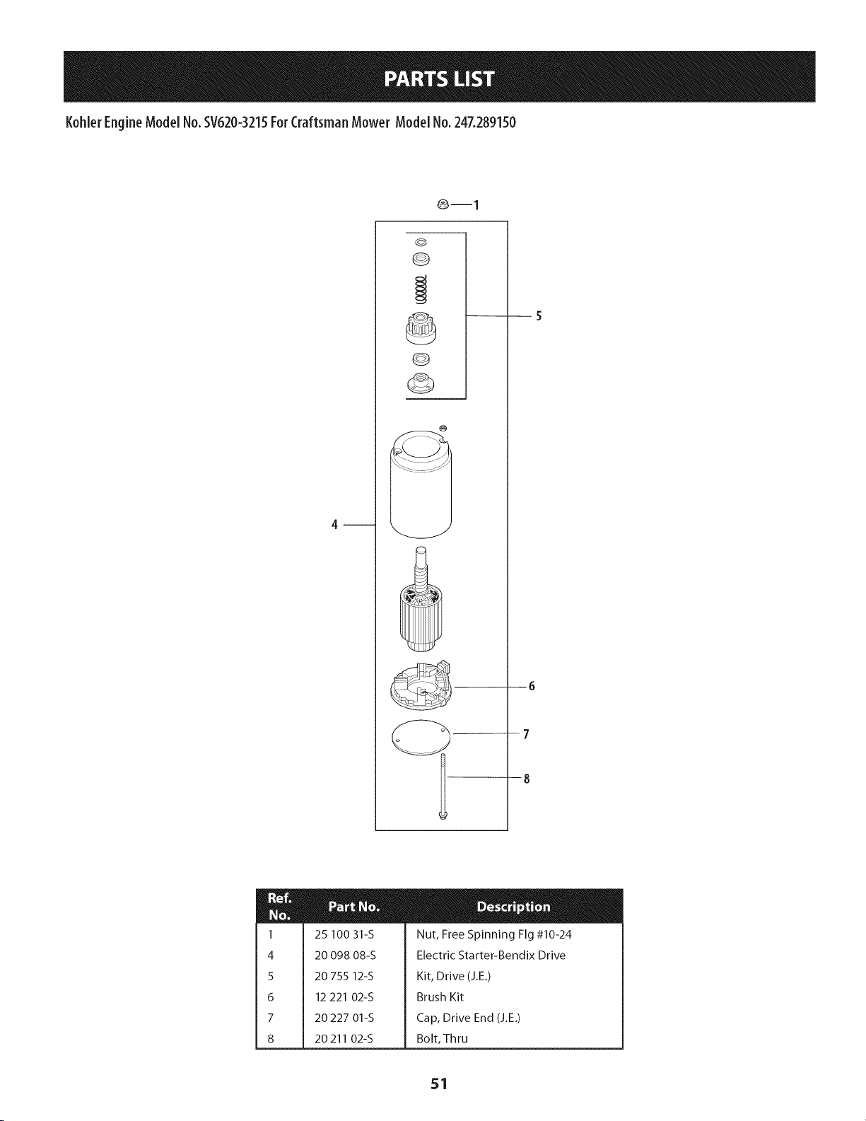
KohlerEngineModelNo.SV620-3215ForCraftsmanMowerModelNo.247.289150
0--1
G
©
--7
--8
m
1
4
5
6
7
8
25 100 31-S
20 098 08-S
20 755 12-S
12 221 02-S
20 227 01-S
20211 02-S
Nut, Free Spinning Fig #10-24
Electric Starter-Bendix Drive
Kit, Drive (J.E.)
Brush Kit
Cap, Drive End (J.E.)
Bolt, Thru
51
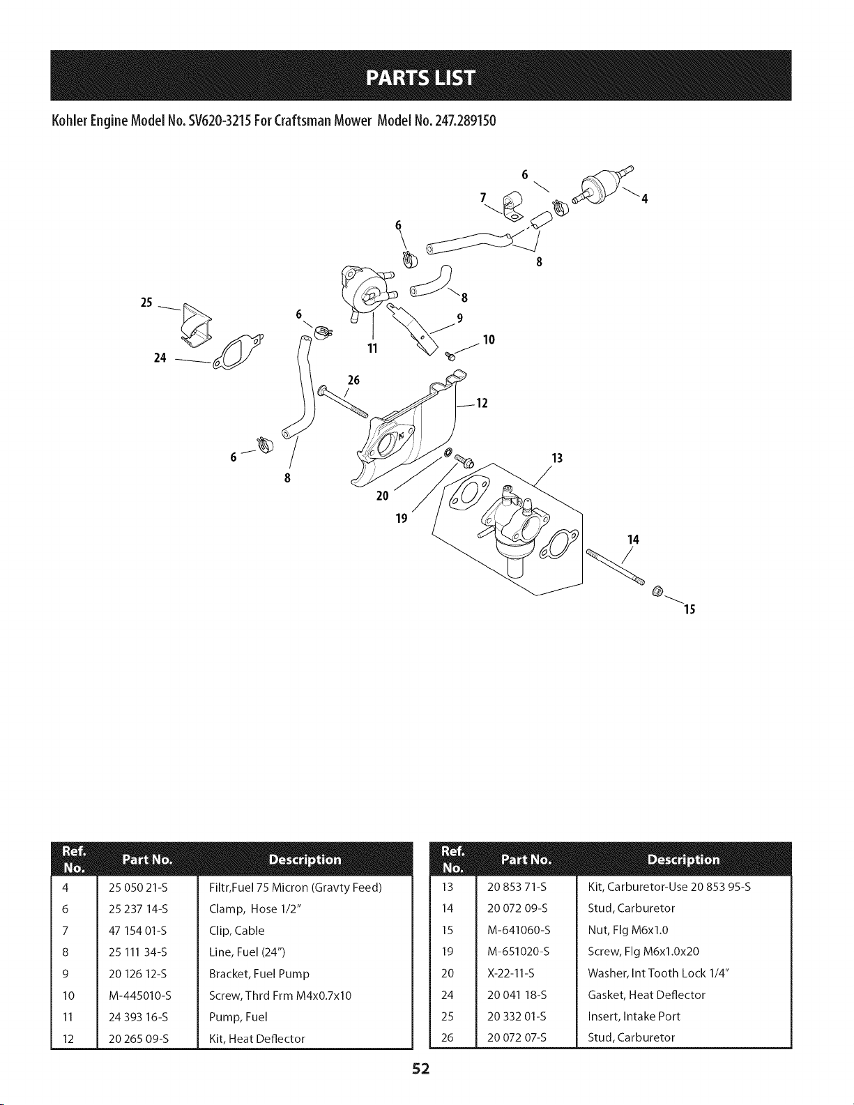
Kohler EngineModel No.SV620-3215For CraftsmanMower Model No. 247.289150
26
/
6
8
_4
20
19
13
14
m
4
6
7
8
9
10
11
12
25 050 21-S
25 237 14-S
47 154 01-S
25 111 34-S
20 126 12-S
M-445010-S
24 393 16-S
20 265 09-S
Filtr, Fue175 Micron (Gravty Feed)
Clamp, Hose 1/2"
Clip, Cable
Line, Fuel (24")
Bracket, Fuel Pump
Screw, Thrd Frm M4xO.7xlO
Pump, Fuel
Kit, Heat Deflector
m
M
13
14
15
19
20
24
25
26
52
20 853 71-S
20 072 09-S
M-641060-S
M-651020-S
X-22-11-S
20 041 18-S
20 332 01-S
20 072 07-S
Kit, Carburetor-Use 20 853 95-S
Stud, Carburetor
Nut, Fig M6xl.0
Screw, Fig M6xl.0x20
Washer, Int Tooth Lock 1/4"
Gasket, Heat Deflector
Insert, Intake Port
Stud, Carburetor
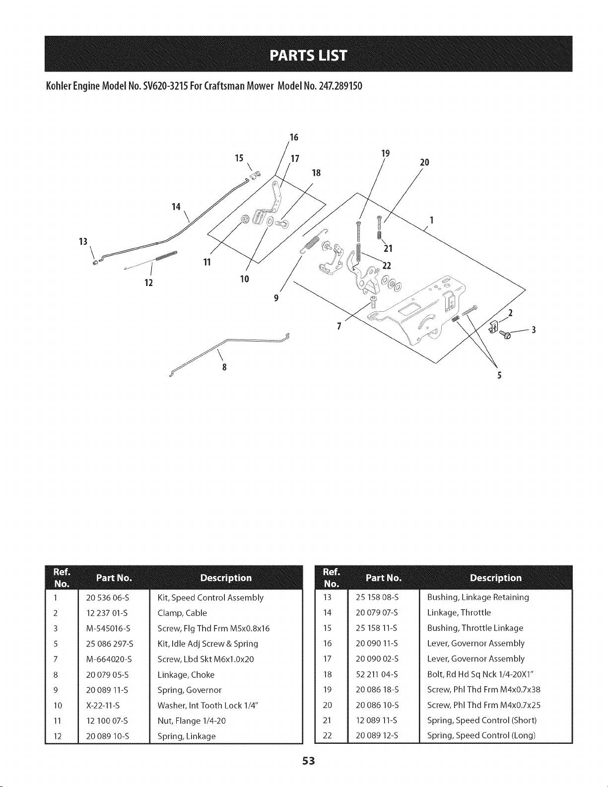
Kohler EngineModel No.SV620-3215ForCraftsman Mower Model No.247.289150
\
16
18
19
2O
12
11
10
9
m
N
u
1
2
3
5
7
8
9
10
11
12
20 536 06-S
12 237 01-S
M-545016-S
25 086 297-S
M-664020-S
Kit, Speed Control Assembly
Clamp, Cable
Screw, Fig Thd Frm M5x0.8x16
Kit, Idle Adj Screw & Spring
Screw, Lbd Skt M6xl.0x20
20 079 05-S
20 089 11-S
X-22-11-S
12 100 07-S
20 089 10-S
Linkage, Choke
Spring, Governor
Washer, Int Tooth Lock 1/4"
Nut, Flange 1/4-20
Spring, Linkage
m
M
13
14
15
16
17
18
19
20
21
22
25 158 08-S
20 079 07-S
25 158 11-S
20 090 11-S
20 090 02-S
52 211 04-S
20 086 18-S
20 086 10-S
12 089 11-S
20 089 12-S
Bushing, Linkage Retaining
Linkage, Throttle
Bushing, Throttle Linkage
Lever, Governor Assembly
Lever, Governor Assembly
Bolt, Rd Hd Sq Nck 1/4-20X1"
Screw, Phi Thd Frm M4x0.7x38
Screw, Phi Thd Frm M4x0.7x25
Spring, Speed Control (Short)
Spring, Speed Control (Long)
53
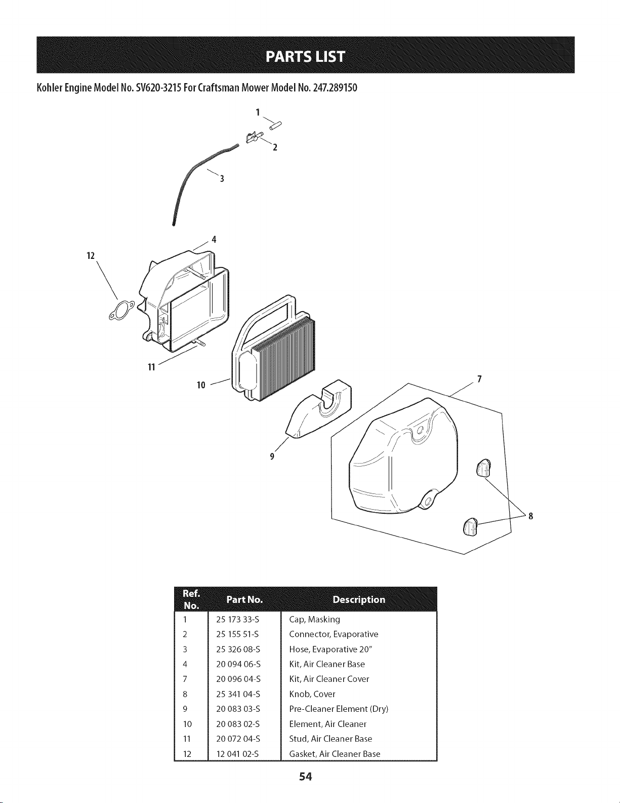
KohlerEngineModelNo.SV620-3215ForCraftsmanMower Model No.247.289150
1
_3
12
\
11
m
1
2
3
4
7
8
9
10
11
12
25 173 33-S
25 155 51-S
25 326 08-S
20 094 06-S
20 096 04-S
25 341 04-S
20 083 03-S
20 083 02-S
20 072 04-S
12 041 02-S
Cap, Masking
Connector, Evaporative
Hose, Evaporative 20"
Kit, Air Cleaner Base
Kit, Air Cleaner Cover
Knob, Cover
Pre-Cleaner Element (Dry)
Element, Air Cleaner
Stud, Air Cleaner Base
Gasket, Air Cleaner Base
S4
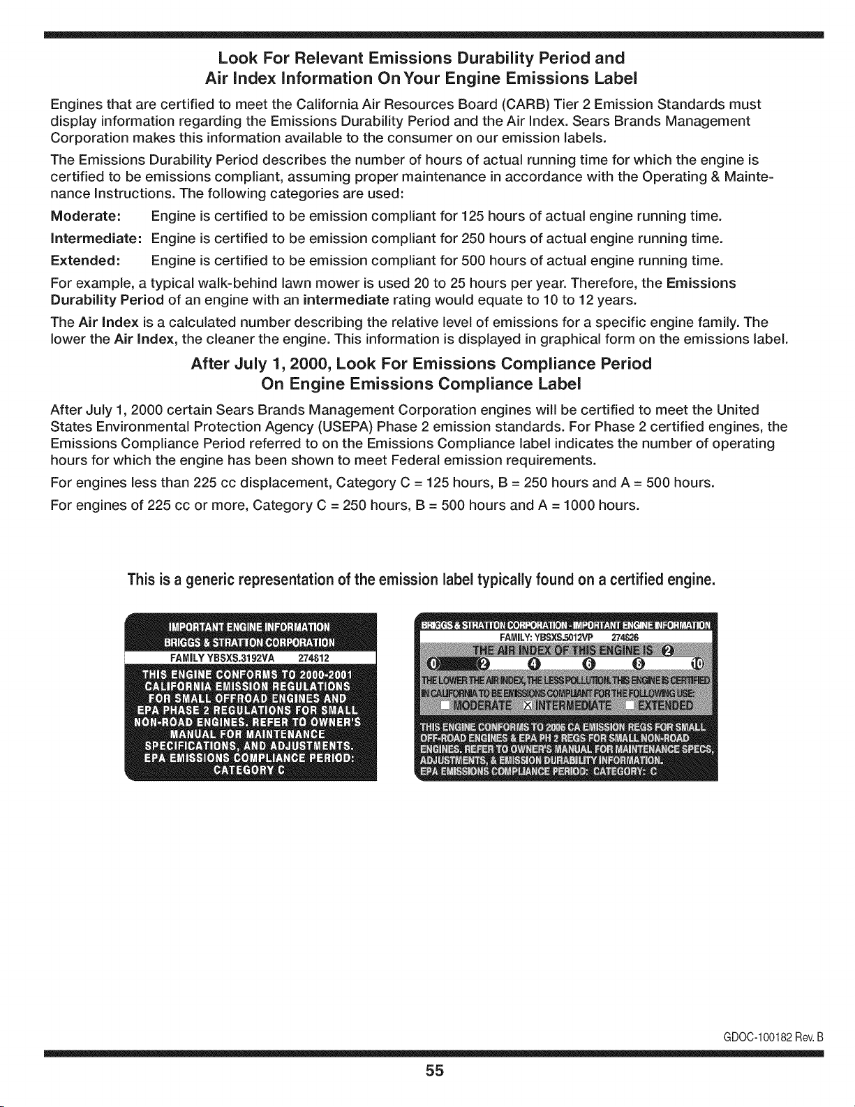
Look For Relevant Emissions Durability Period and
Air index information On Your Engine Emissions Label
Engines that are certified to meet the California Air Resources Board (CARB) Tier 2 Emission Standards must
display information regarding the Emissions Durability Period and the Air Index. Sears Brands Management
Corporation makes this information available to the consumer on our emission labels.
The Emissions Durability Period describes the number of hours of actual running time for which the engine is
certified to be emissions compliant, assuming proper maintenance in accordance with the Operating & Mainte-
nance Instructions. The following categories are used:
Moderate: Engine is certified to be emission compliant for 125 hours of actual engine running time.
Intermediate: Engine is certified to be emission compliant for 250 hours of actual engine running time.
Extended: Engine is certified to be emission compliant for 500 hours of actual engine running time.
For example, a typical walk-behind lawn mower is used 20 to 25 hours per year. Therefore, the Emissions
Durability Period of an engine with an intermediate rating would equate to 10 to 12 years.
The Air index is a calculated number describing the relative level of emissions for a specific engine family. The
lower the Air Index, the cleaner the engine. This information is displayed in graphical form on the emissions label.
After July 1,2000, Look For Emissions Compliance Period
On Engine Emissions Compliance Label
After July 1, 2000 certain Sears Brands Management Corporation engines will be certified to meet the United
States Environmental Protection Agency (USEPA) Phase 2 emission standards. For Phase 2 certified engines, the
Emissions Compliance Period referred to on the Emissions Compliance label indicates the number of operating
hours for which the engine has been shown to meet Federal emission requirements.
For engines less than 225 cc displacement, Category C = 125 hours, B = 250 hours and A = 500 hours.
For engines of 225 cc or more, Category C = 250 hours, B = 500 hours and A = 1000 hours.
This is a generic representation of the emission label typically found on a certified engine.
FAMILYYBSXS.3192VA 274812
GDOC-100182Rev.B
55
(Thispageapplicableinthe U.S.A.and Canadaonly.)
Sears Brands Management Corporation (Sears), the California Air Resources Board (CARD)
and the United States Environmental Protection Agency (U.S. EPA)
Emission Control System Warranty Statement (Owner's Defect Warranty Rights and Obligations)
EMISSIONCONTROLWARRANTYCOVERAGEISAPPLICABLETOCERTI-
FIEDENGINESPURCHASEDIN CALIFORNIAIN 1995ANDTHEREAF-
TER,WHICHARE USED INCALIFORNIA,ANDTO CERTIFIEDMODEL
California and United States Emission
The CaliforniaAir ResourcesBoard(CARD),U.S.EPAand Searsare pleased
to explainthe EmissionControlSystemWarrantyon your modelyear2000and
latersmalloff-roadengine(SORE).InCalifornia,newsmall off-roadengines
mustbe designed,builtand equippedto meettheState'sstringentanti-smog
standards.Elsewherein theUnitedStates, newnon-road,spark-ignition
enginescertifiedfor modelyear 1997and latermustmeetsimilarstandardsset
forth bythe U.S.EPA.Sears mustwarrantthe emissioncontrol systemonyour
YEAR 1997AND LATERENGINESWHICHARE PURCHASEDAND USED
ELSEWHEREIN THE UNITEDSTATES(ANDAFTERJANUARY1,2001 IN
CANADA).
Control Defects Warranty Statement
enginefor theperiodsoftime listedbelow,providedtherehas been noabuse,
neglector impropermaintenanceof your smalloff-roadengine.Youremis-
sion controlsystemincludespartssuch as the carburetor,air cleaner,ignition
system,mufflerand catalyticconverter.Also includedmaybe connectorsand
otheremissionrelatedassemblies.Wherea warrantableconditionexists,Sears
will repairyour smalloff-roadengineat no costto you includingdiagnosis,parts
and labor.
Sears Emission Control Defects Warranty Coverage
Smalloff-roadenginesarewarrantedrelativeto emissioncontrolpartsdefects
fora periodof one year,subjectto provisionsset forth below.Ifany covered
Owner's Warranty
Asthe smalloff-roadengine owner,you are responsiblefor theperformanceof
therequiredmaintenancelistedin yourOperatingand MaintenanceInstruc-
tions.Searsrecommendsthatyou retain all yourreceiptscoveringmaintenance
on yoursmalloff-roadengine,butSears cannotdenywarrantysolelyfor the
lackof receiptsorfor yourfailureto ensurethe performanceof all scheduled
maintenance.As the smalloff-roadengineowner,you shouldhoweverbe
awarethat Searsmaydenyyou warrantycoverageif your smalloff-roadengine
ora part hasfailed dueto abuse,neglect,impropermaintenanceor unap-
parton yourengineis defective,the part willbe repairedorreplacedbySears.
Responsibilities
provedmodifications.Youare responsiblefor presentingyour smalloff-road
engineto an AuthorizedSearsServiceDealeras soonas a problemexists.The
undisputedwarrantyrepairsshouldbe completedina reasonableamountof
time,notto exceed30 days. Ifyou haveany questionsregardingyourwarranty
rightsand responsibilities,you shouldcontacta SearsService Representative
at 1-800-469-4663.The emissionwarrantyis a defectswarranty.Defectsare
judgedon normalengineperformance.The warrantyis notrelatedto an in-use
emissiontest.
Sears Emission Control Defects Warranty Provisions
ThefollowingarespecificprovisionsrelativetoyourEmissionControlDefectsWarrantyCoverage.ItisinadditiontotheSearsenginewarrantyfornon-regulated
enginesfound in theOperatingand MaintenanceInstructions.
1. WarrantedParts
Coverageunderthis warrantyextendsonly to the parts listedbelow (the
emissioncontrolsystemsparts)to the extentthese partswere presenton
theengine purchased.
a. FuelMeteringSystem
• Cold start enrichmentsystem
• Carburetorand internalparts
• FuelPump
b. Air lnduction System
• Air cleaner
• Intakemanifold
c. IgnitionSystem
• Spark plug(s)
• Magnetoignitionsystem
d. CatalystSystem
• Catalyticconverter
• Exhaustmanifold
• Air injectionsystemor pulsevalve
e. MiscellaneousItemsUsedin AboveSystems
• Vacuum,temperature,position,timesensitivevalves
andswitches
• Connectorsandassemblies
2. Lengthof Coverage
Searswarrantsto the initialownerand eachsubsequentpurchaserthat
theWarrantedPartsshallbe free from defects in materialsandworkman-
shipwhich causedthefailure of the WarrantedPartsfor a periodof one
yearfrom the datethe engineis deliveredto a retailpurchaser.
3. NoCharge
Repairor replacementof anyWarrantedPartwill be performedat no
chargeto the owner,includingdiagnosticlabor whichleadsto the
determinationthata WarrantedPartis defective,if the diagnosticwork is
performedat an AuthorizedSearsServiceDealer.Foremissionswarranty
servicecontact yournearestAuthorizedSearsServiceDealeras listed in
the "YellowPages"under"Engines,Gasoline,""GasolineEngines,""Lawn
Mowers,"or similar category.
4. Claimsand CoverageExclusions
Warrantyclaimsshall be filed in accordancewiththe provisionsof the
Sears EngineWarrantyPolicy.Warrantycoverageshall be excludedfor
failuresof WarrantedPartswhichare not original Sears partsor because
of abuse, neglector impropermaintenanceas setforth inthe Sears
EngineWarrantyPolicy.Sears is notliableto coverfailuresof Warranted
Partscausedby theuse of add-on,non-original,or modifiedparts.
5. Maintenance
Any WarrantedPart whichis notscheduledfor replacementas required
maintenanceor whichis scheduledonly for regularinspectionto the effect
of "repairor replaceas necessary"shallbe warrantedas to defectsfor the
warrantyperiod.Any WarrantedPartwhich is scheduledfor replacement
as requiredmaintenanceshallbe warrantedas to defectsonly forthe
periodof time upto the firstscheduledreplacementfor that part. Any
replacementpart that is equivalentin performanceand durabilitymay
be usedin the performanceof any maintenanceor repairs.The owneris
responsibleforthe performanceof all requiredmaintenance,as definedin
the SearsOperatingand MaintenanceInstructions.
6. ConsequentialCoverage
Coveragehereundershallextendto the failure of any engine components
caused bythe failureof any WarrantedPartstill underwarranty.
Inthe USAandCanada,a 24 hour hotline, 1-800-469-4663,has a menu of pre-recordedmessagesofferingyou enginemaintenanceinformation.
GDOC-100188Rev.B
56
FEDERALand/or CALIFORNIAEMISSIONCONTROLWARRANTYSTATEMENT
YOURWARRANTYRIGHTSANDOBLIGATIONS
MTD Consumer Group Inc, the United States Environmental Protection Agency (EPA), and, for those products certified for sale in the state of
California, the California Air Resources Board (CARB) are pleased to explain the emission (evaporative and/or exhaust) control system (ECS)
warranty on your outdoor 2006 and later small off-road spark-ignited engine and equipment (outdoor equipment engine) In California, new
outdoor equipment engines must be designed, built and equipped to meet the State's stringent anti-smog standards (in other states, 1997 and
later model year equipment must be designed, built, and equipped to meet the U.S. EPA small off-road, spark ignition engine regulations. MTD
Consumer Group Inc must warrant the ECSon your outdoor equipment engine for the period of time listed below provided there has been no
abuse, neglect or improper maintenance of outdoor equipment engine.
Your ECS may include parts such as the carburetor, fuel-injection system, the ignition system, catalytic converter, fuel tanks, fuel lines, fuel caps,
valves, canisters, filters, vapor hoses, clamps, connectors, and other associated emission-related components.
Where a warrantable condition exists, MTD Consumer Group Inc will repair your outdoor equipment engine at no cost to you including
diagnosis, parts and labor.
MANUFACTURER'SWARRANTYCOVERAGE:
This emission control system is warranted for two years. If any emission-related part on your outdoor equipment engine is defective, the part
will be repaired or replaced by MTD CONSUMER GROUP INC.
OWNER'SWARRANTYRESPONSIBILITIES:
As the outdoor equipment engine owner, you are responsible for performance of the required maintenance listed in your owner's manual. MTD
Consumer Group Inc recommends that you retain all receipts covering maintenance on your outdoor equipment engine, but MTD Consumer
Group Inc cannot deny warranty solely for the lack of receipts.
As the outdoor equipment engine owner, you should however be aware that MTD Consumer Group Inc may deny you warranty coverage if
your outdoor equipment engine or a part has failed due to abuse, neglect, or improper maintenance or unapproved modifications.
You are responsible for presenting your outdoor equipment engine to MTD Consumer Group Inc's distribution center or service center as soon
as the problem exists. The warranty repairs should be completed in a reasonable amount of time, not to exceed 30 days. If you have a question
regarding your warranty coverage, you should contact the MTD Consumer Group Inc Service Department at 1-800-800-7310 or via email at
http://su pport.mtd prod ucts.com
GENERALEMISSIONSWARRANTYCOVERAGE:
MTD Consumer Group Inc warrants to the ultimate purchaser and each subsequent purchaser that the outdoor equipment engine is: Designed,
built and equipped so as to conform with all applicable regulations; and free from defects in materials and workmanship that cause the failure
of a wa rranted part to be identical in all material respects to that part as described in MTD Consumer Group Inc's application for certification.
The warranty period begins on the date the outdoor equipment engine is delivered to an ultimate purchaser or first placed into service. The
warranty period is two years.
Subject to certain conditions and exclusions as stated below, the warranty on emission-related parts is as follows:
1. Any warranted part that is not scheduled for replacement as required maintenance in the written instructions supplied, is warranted for
the warranty period stated above. If the part fails during the period of warranty coverage, the part will be repaired or replaced by MTD
Consumer Group Inc according to subsection (4) below. Any such part repaired or replaced under warranty will be warranted for the
remainder of the period.
2. Any warranted part that is scheduled only for regular inspection in the written instructions supplied is warranted for the warranty period
stated above. Any such part repaired or replaced under warranty will be warranted for the remaining warranty period.
3. Any warranted part that is scheduled for replacement as required maintenance in the written instructions supplied is warranted for the
period of time before the first scheduled replacement date for that part. If the part fails before the first scheduled replacement, the part
will be repaired or replaced by MTD Consumer Group Inc according to subsection (4) below. Any such part repaired or replaced under
warranty will be warranted for the remainder of the period prior to the first scheduled replacement point for the part.
Repair or replacement of any warranted part under the warranty provisions herein must be performed at a warranty station at no charge
to the owner.
4.
5. Notwithstanding the provisions herein, warranty services or repairs will be provided at all of our distribution centers that are franchised to
service the subject engines or equipment.
6. The outdoor equipment engine owner will not be charged for diagnostic labor that is directly associated with diagnosis of a defective,
emission-related warranted part, provided that such diagnostic work is performed at a warranty station.
7. MTD Consumer Group Inc is liable for damages to other engine or equipment components proximately caused by a failure under
warranty of any warranted part.
8. Throughout the off-road engine and equipment warranty period stated above, MTD Consumer Group Inc will maintain a supply of
warranted parts sufficient to meet the expected demand for such parts.
9. Any replacement part may be used in the performance of any warranty maintenance or repairs and must be provided without charge to
the owner. Such use will not reduce the warranty obligations of MTD Consumer Group Inc.
10. Add-onormodifiedpartsthatarenotexemptedbytheAirResourcesBoardmaynotbeused.Theuseofanynon-exemptedadd-onor
modifiedpartsbytheultimatepurchaserwillbegroundsfordisallowingawarrantyclaims.MTDConsumerGroupIncwillnotbeliableto
warrantfailuresofwarrantedpartscausedbytheuseofanon-exemptedadd-onormodifiedpart.
WARRANTEDPARTS:
The repair or replacement of any warranted part otherwise eligible for warranty coverage may be excluded from such warranty coverage if
MTD Consumer Group Inc demonstrates that the outdoor equipment engine has been abused, neglected, or improperly maintained, and that
such abuse, neglect, or improper maintenance was the direct cause of the need for repair or replacement of the part. That notwithstanding,
any adjustment of a component that has a factory installed, and properly operating, adjustment limiting device is still eligible for warranty
coverage. Further, the coverage under this warranty extends only to parts that were present on the off-road engine and equipment purchased.
The following emission warranty parts are covered (if applicable):
1. Fuel Metering System
Cold start enrichment system (soft choke)
Carburetor and internal parts (or fuel injection system)
Fuel pump
Fuel tank
2. Air Induction System
Air cleaner
Intake manifold
3. Ignition System
Spark plug(s)
Magneto ignition system
4. Exhaust System
Catalytic converter
SAI (Reed valve)
5. Miscellaneous Items Used in Above System
Vacuum, temperature, position, time sensitive valves and switches
Connectors and assemblies
6. Evaporative Control
Fuel hose
Fuel hose clamps
Tethered fuel cap
Carbon canister
• Vapor lines
GDOG100223Rev.A

Congratulations on making a smart purchase. Your new Craftsman® product is designed and
manufactured for years of dependable operation. But like all products, it may require repair
from time to time. That's when having a Repair Protection Agreement can save you money and
aggravation.
Here's what the Repair Protection Agreement* includes:
[] Expert service by our 10,000 professional repair specialists
[] Unlimited service and no charge for parts and labor on all covered repairs
[] Product replacement up to $1500 if your covered product can't be fixed
[] Discount of 25% from regular price of service and related installed parts not covered by the
agreement; also, 25% off regular price of preventive maintenance check
[] Fast help by phone - we call it Rapid Resolution - phone support from a Sears representative.
Think of us as a "talking owner's manual."
Once you purchase the Repair Protection Agreement, a simple phone call is all that it takes for you
to schedule service. You can call anytime day or night, or schedule a service appointment online.
The Repair Protection Agreement is a risk-free purchase. If you cancel for any reason during the
product warranty period, we will provide a full refund. Or, a prorated refund anytime after the
product warranty period expires. Purchase your Repair Protection Agreement today!
Some limitations and exclusions apply. For prices and additional information in the U.S.A.
call 1=800=827=6655.
*Coverage in Canada varies on some items. For full details call Sears Canada at 1=800=361=
6665.
Sears Installation Service
For Sears professional installation of home appliances, garage door openers, water heaters, and
other major home items, in the U.S.A. or Canada call 1=800=4=MY=HOME®.
59
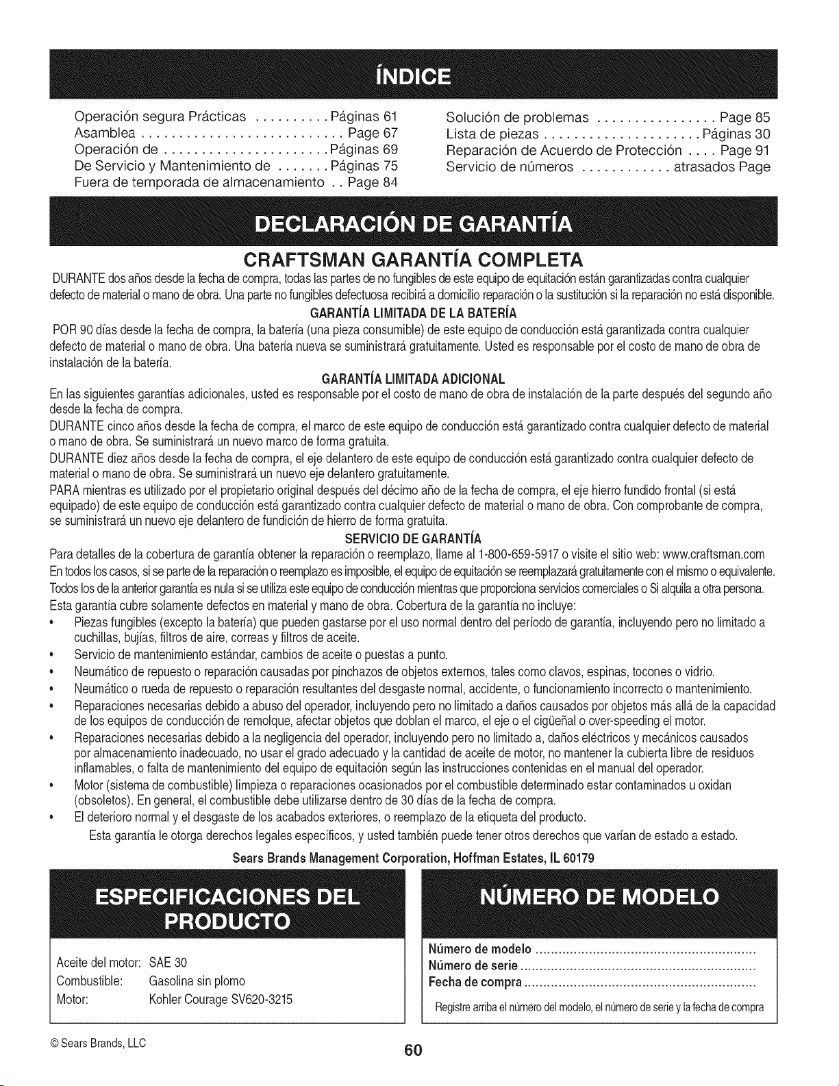
Operaci6n segura Pr,_cticas .......... Paginas 61 Soluci6n de problemas ................ Page 85
Asamblea ........................... Page 67 Lista de piezas ..................... Paginas 30
Operaci6n de ...................... Paginas 69 Reparaci6n de Acuerdo de Protecci6n .... Page 91
De Servicio y Mantenimiento de ....... Paginas 75 Servicio de nOmeros ............ atrasados Page
Fuera de temporada de almacenamiento .. Page 84
CRAFTSMAN GARANTiA COMPLETA
DURANTEdosa_osdesdela fechadecompra,todaslaspartesde nofungiblesdeesteequipode equitaci6nestangarantizadascontracualquier
defectode materialo manodeobra.UnapartenofungiblesdefectuosarecibirAa domicilioreparaci6no la sustituci6nsila reparaci6nnoestAdisponible.
GARANT{ALIMITADADE LABATER{A
POR90 diasdesde lafechadecompra,la bateria(unapiezaconsumibJe)de este equipode conducci6nestagarantizadacontracualquier
defectode materialo manodeobra. Unabaterianuevase suministrar_gratuitamente.Ustedes responsableporelcostode manodeobra de
instalaci6nde la bateria.
GARANTIALJMITADAADICJONAL
Enlas siguientesgaranfiasadicionales,ustedes responsaNepor el costodemanode obrade instalacbnde la partedespu_sdel segundoaSo
desdelafechadecompra.
DURANTEcincoaSosdesdelafecha de compra,el marcodeeste equipode conduccbnest,. garantizadocontracualquierdefectode material
o manodeobra.Se suministrar_,unnuevomarcode forma gratuita.
DURANTEdiezaSosdesde la fecha de compra,el ejedelanterodeesteequipode conducci6nest,.garantizadocontracualquierdefectode
materialo manode obra. Sesuministrar_,unnuevoeje delanterogratuitamente.
PARAmientrases utilizadopor el propietariooriginaldespuesdel d_cimoaSode la fecha de compra,el eje hierrofundidofrontal (si est,.
equipado)deesteequipo de conducci6nest,. garantizadocontracualquierdefectode materialo manode obra.Concomprobantede compra,
se suministrar_,un nuevoeje delanterodefundici6nde hierrodeforma gratuita.
SERVlCIODEGARANT{A
Paradetallesde lacoberturade garantiaobtenerla reparaci6no reemplazo,Ilameal 1-800-659-5917ovisite el sitio web: www.craftsman.com
Entodosloscasos,sisepartedelareparacbno reemplazoesimposible,el equipodeequitacbnsereemplazar_,gratuitamenteconelmismooequivalente.
Todoslosdelaanteriorgarantiaesnulasiseutilizaesteequipodeconduccbnmientrasqueproporcionaservicioscomercialeso Sialquilaaotrapersona.
Estagarantiacubresolamentedefectosen materialy manode obra. Coberturade la garantianoinduye:
• PiezasfungiNes(exceptola bateria)que puedengastarseporel uso normaldentrodelperiodode garantia,incluyendoperono limitadoa
cuchillas,bujias,filtrosde aire,correasy filtros deaceite.
• Serviciode mantenimientoest_.ndar,cambiosde aceiteo puestasa punto.
• Neum_.ticode repuestoo reparaci6ncausadasporpinchazosde objetosexternos,tales comoclavos,espinas,toconeso vidrio.
• Neum_.ticoo ruedade repuestoo reparaci6nresultantesdeldesgastenormal,accidente,o funcionamientoincorrectoo mantenimiento.
• Reparacionesnecesariasdebidoa abusodel operador,incluyendopero no limitadoa daSoscausadosporobjetosm_.sall_.de la capacidad
de losequiposde conducci6nde remoique,afectarobjetosquedoblanel marco,el ejeo el cig(JeSalo over-speedingel motor.
• Reparacionesnecesariasdebidoa lanegligenciadeloperador,incluyendoperono limitadoa, daSosel_ctricosy mec_.nicoscausados
poralmacenamientoinadecuado,no usarelgradoadecuadoy la cantidadde aceitede motor,no mantenerla cubiertalibre de residuos
inflamables,o falta de mantenimientodelequipode equitaci6nsegQnlas instruccionescontenidasen el manualdeloperador.
• Motor(sistemadecombustible)limpiezao reparacionesocasionadospot el combustibledeterminadoestarcontaminadosu oxidan
(obsoletos).Engeneral,el combustibledebeutilizarsedentrode 30 diasde la fechade compra.
• Eldeterioronormaly el desgastedelos acabadosexteriores,o reemplazodela etiquetadel producto.
Estagarantialeotorgaderechoslegalesespecificos,y ustedtambi_npuedetenerotrosderechosquevariande estadoa estado.
Sears Brands Management Cm
Aceitedel motor: SAE30
Combustible: Gasolinasinplomo
Motor: KohlerCourageSV620-3215
)oration, Hoffman Estates, IL 60179
NSmerode modelo ..........................................................
N_mero de serie ..............................................................
Fechade eompra .............................................................
Registrearribaeln_merodelmodelo,eln_merodeserieylafechadecompra
© SearsBrands,LLC 60
Lapresenciadeeste sirnboloindicaque setrata de instrucciones
irnportantesde seguridadquese deben respetarpara evitar
poneren peligrosu seguridadpersonaly/o materialy lade otras
personas.Lea y siga todaslas instruccionesdeestemanualantes
de poneren funcionarnientoestarn_.quina.Si no respetaestas
instruccionespodriaprovocarlesionespersonales.Cuandoveaeste
sirnbolo,ipresteatenci6na la advertencia!
PROPOSICION 65 DE CALIFORNIA
Elescapedel motordeeste producto,algunosde suscornponentes
y algunoscornponentesdel vehiculocontieneno liberan sustancias
quirnicasqueel estado de Californiaconsideraque puedenproducir
c_.ncer,defectosde nacirnientouotros problernasreproductivos.
Losbornesde la bateriay los accesoriosalinescontienenplornoy
cornpuestosde plorno,sustanciasquirnicasque segOnIo estableci-
do pot el Estadode Californiacausanc_.ncery da_osen el sisterna
reproductivo.Ldveselas manos despu_sde estaren contacto
con estoscomponentes.
Estarn_.quinarue construidaparaseroperadadeacuerdocon
las reglasde seguridadcontenidasen este manual.AI igualque
concualquiertipo deequipornotorizado,un descuidoo error por
partedeloperadorpuedeproducirlesionesgraves.Estarn_.quina
es capazde arnputarrnanosy piesy de arrojarobjetoscon gran
fuerza.Deno respetarlas instruccionesde seguridadsiguientesse
puedenproducirlesionesgraveso la rnuerte.
Su responsabilidad--Restrinja el usode estarn_.quina
rnotorizadaalas personasque lean,cornprendany respetenlas
advertenciase instruccionesqueaparecenen este manualyen la
rn_.quina.
iGUARDEESTASINSTRUCCIONES!
FUNCIONAMIENTO GENERAL
• Lea,entienday curnplatodaslas instruccionesincluidasen
la rn_.quinayen los rnanualesantesde rnontarlay utilizarla.
Guardeestemanualenun lugarseguroparaconsultasfuturasy
peri6dicas,asi cornopara solicitarrepuestos.
• Farniliaricesecontodoslos controlesy con el usoadecuado
delos rnisrnos.Sepa c6rnodetenerlarn_.quinay desactivarlos
controlesr_.pidarnente.
• No perrnitanuncaque los ni_osrnenoresde 14a_osutilicen
estarn_.quina.Los ni_osde 14a_osen adelantedebenleer y
entenderlas instruccionesde operaci6ny norrnasdeseguridad
contenidaseneste manual,y en la rn_.quinay debenser
entrenadosy supervisadospor un adulto.
• Nuncaperrnitaque los adultosoperenestarn_.quinasin recibir
antesla instrucci6napropiada.
• Paraayudara evitar el contactocon las cuchillaso unalesi6npor
algOnobjetoquesea arrojado,rnantengaa los observadores,a
los ayudantes,ni_osy rnascotasalejadosal rnenos25 metrosde
la rn_.quinarnientrasest,.en funcionarniento.Detengala rn_.quina
si alguienentraen la zona.
• Inspeccionerninuciosarnenteel Areadondeutilizar_,el equipo.
Retiretodaslas piedras,palos,cables,huesos,juguetesy otros
objetosextra_osque podrianser recogidosy arrojadospor la
acci6nde las cuchillas.Losobjetosarrojadospor larn_.quina
puedenproducirlesionesgraves.
• Planifiqueel patr6nde corte del c_spedque ha de seguirpara
evitarla descargade materialhacialoscarninos,las veredas,los
observadores,etc.Eviteadern_.sdescargarmaterialcontralas
paredesy obstruccionesquepodrianprovocarqueel material
descargadorebotecontrael operador.
• Paraprotegerselos ojos utilicesiernpreanteojoso antiparras
deseguridadrnientrasoperalarn_.quinao rnientrasla ajusta
o repara.Losobjetosarrojadosque rebotanpuedenproducir
lesionesocularesgraves.
• Utilicezapatosde trabajoresistentes,desuelafuerte,asi corno
pantalonesy carnisasajustados.Las prendassueltaso las
alhajaspuedenquedaratrapadasenlas piezasrnovibles.Nunca
operela rn_.quinadescalzoo con sandalias.
• Est_atentoa la cortadoray a la direcci6nde la descargade
losaditarnentosy no apuntea nadie.Nuncaoperela cortadora
de c_spedsin que est_nen su lugarapropiadolacubiertade
descargao elcolectorde recortesde cesped.
• Nopongalasrnanoso lospies cercade las piezasrotatoriaso
debajode la plataforrnadecorte. El contactocon las cuchillas
puedeproducirla arnputaci6ndernanosy pies.
• Unacubiertade descargafaltanteo da_adapuedeprovocarel
contactocon la cuchillao lesionespot objetosarrojados.
• Detengala(s)cuchilla(s)cuandoatraviesesenderos,sendaso
carninosde gravay cuandonoest_cortandoel cesped.
• Vigileel tr_.nsitovehicularcuandoest_operandocercadeo en
crucesde carninos.Estarn_.quinanodebeutilizarseen la via
pOblica.
• Noopereestarn_.quinabajolosefectosdel alcoholode drogas.
• Corteel cespedsolarnentecon luzdedia o conunabuenaluz
artificial.
• Nuncatransportepasajeros.
• Desenganchela(s)cuchilla(s)antesdecolocarlarnarchaatr_.s.
Retrocedalentarnente.Siernpremirehaciaabajoy haciaatr_.santes
y rnientrasretrocede,paraevitaraccidentes.
• Reduzcala velocidadantesdedarlavuelta.Operelarn_.quina
suavernente.Evitelaoperaci6nerr_.ticay la velocidadexcesiva.
• Desenganchela(s)cuchilla(s),coloqueel frenodeestaciona-
rniento,detengael motory esperehastaque la(s)cuchilla(s)se
detenga(n)porcornpletoantesderetirarelcolectordec_sped,
vaciarlos recortes,destaparelcanal,retirarrestosde cespedo
desechos,o hacercualquierajuste.
61
• Nuncadejelarn_.quinaen funcionarnientosinvigilancia.Apague
siernprelascuchillas,coloqueel frenode rnano,detengaelmotory
retirela Ilaveantesde bajarsedel vehiculo.
• Tengasurnocuidadoalcargaro descargarlarn_.quinaen un
rernolqueocarni6n.Estaunidadnodebeconducirseen ascensoo
descensoderarnpas,porquepodrialadearsey provocarlesiones
personalesgraves.En las rarnpaslarn_.quinasedebeernpujar
rnanualrnenteparacargarlao descargarlacorrectarnente.
• Elsilenciadory el motorse calientany puedencausarquernaduras.
Nolos toque.
• Reviseel espaciolibrepot encirnade lacabezaantesdeconducir
bajolas rarnasbajasde_.rboles,cables,cerrarnientosde puertas,
etc.enloscualesel operadorpodriaatorarseo serernpujadofuera
dela rn_.quina,Ioquepodriaresultaren lesionesgraves.
• Desenganchetodoslosernbraguesdelos accesoriosy presione
totalrnenteel pedaldel frenoantesdeintentararrancarel motor.
• Larn_.quinaest,.diseSadaparacortarc_spedresidencialnormal,
conunaalturano mayora 10".Nointentecortarcespeddernasiado
crecido,seco(porej.,pastura)nipilasde hojassecas.Elc_sped
y las hojassecaspuedenentraren contactoconel escapedel
motory/o acurnularseen la plataforrnade la cortadorade cesped,
convirti_ndoseen unpeligrodeincendio
• Utilicesolarnenteaccesoriosy aditarnentosaprobadosparaesta
rn_.quinapot elfabricantedelarnisrna.Lea,cornprenday siga
todaslasinstruccionesproporcionadasconlosaccesorioso
aditarnentosaprobados.Paraobteneruna listade losaccesorios
aprobadosy losarchivosadjuntos,Ilarne1-800-659-5917.
• Losdatosestadsticosrnuestranquelosoperadoresde60 aSos
y rnayoresseven involucradosen un altoporcentajedelesiones
relacionadascontractorescortacesped.Estosoperadoresdeben
evaluarsu capacidadparaoperarel tractorcortac_speden forrna
suficienternentesegurapara protegersea ellosrnisrnosy alos
dern_.scontralesionesgraves.
Si se presentansituacionesqueno est_.nprevistasen este
manualsea cuidadosoy use el sentidocornOn.
FUNCIONAiVIIENTO EN PENDIENTES
Las pendientesson un factorirnportanterelacionadoconaccidentes
porderrapey vuelcosquepuedenproducirlesionesgravese incluso
la rnuerte.Laoperaci6nen pendientesrequieremayorprecauci6n.
Si nopuederetrocederen la pendienteo si no se sienteseguro,no
realiceningunaoperaci6ndecorte.
Parasu seguridad,use el indicadorde pendientesque se incluye
cornopartede estemanualpararnedirla pendienteantesdeoperarla
rn_.quinaen una zonainclinada.Si la pendientees mayorde 15 grados
segOnel rnedidor,no opereestarn_.quinaen ese sector,puespodria
causarlesionesgraves.
HagaIo siguiente:
• Podehaciaarribay abajodelas pendientes,nodeforrnatrans-
versal.Tengacuidadocuandocarnbiededirecci6nal operaren
pendiente.
• Est_atentoa loshoyos,surcos,baches,rocas,uotrosobjetos
ocultos.Elterrenodesniveladopuedevoltearla rn_.quina.El cesped
altopuedeocultarobst_.culos.
• Vayaa bajavelocidad.ElijaunavelocidadIosuficienternentebaja,
de rnodoquenotengaquedetenerseohacercarnbiosrnientras
est,.sobrela pendiente.Losneurn_.ticospodrianperdertracci6n
sobrelaspendientesaQncuandolosfrenosfuncionaranapro-
piadarnente.Siernprernantengalarn_.quinaen carnbiornientras
desciendelaspendientes,parapoderfrenarconel motor.
• Sigalas recornendacionesdel fabricanteparalos pesoso contra-
pesosdelas ruedas,pararnejorarlaestabilidadde la rn_.quina.
• Tengaespecialcuidadocon loscolectoresdecespeduotros
aditarnentos.Losrnisrnospuedenrnodificarlaestabilidaddela
rn_.quina.
• Hagaquetodoslos rnovirnientosen laspendientesseanlentosy
graduales.Nocarnbierepentinarnentela velocidadni la direcci6n.
Unfrenadoo carnbiode velocidadrepentinospuedencausarque
el frentede larn_.quinase levantey d_unavolteretahaciaatr_.s,Io
quepodriaproducirlesionesgraves.
• Evitearrancaro detenerseenunapendiente.Silosneurn_.ticos
pierdenlatracci6n,desenganchelascuchillasy descienda
lentarnentela pendiente.
No hagaIo siguiente:
• Nogiresobrelas pendientesarnenosqueseanecesario.Sies
posible,girelentarnentey gradualrnenteduranteeldescenso.
• Nocorteelc_spedcercade pozos,hundirnientoso terraplenes.La
cortadoradec_spedpuedevolcarserepentinarnentesiunade las
ruedasestersobreel hordede unacantilado,zanjao siunhordese
desrnorona.
• Nointenteestabilizarlarn_.quinaponiendoelpie enel suelo.
• Noutiliceuncolectordec_speden pendientesernpinadas.
• NopodeelcespedhOrnedo.Unarnenortracci6npodriacausar
derrapes.
• Noparadescender.El excesode velocidadpuedehacerqueel
operadorpierdael controldela rn_.quina,ocasionandolesiones
graveseinclusolarnuerte.
• Norernolquecargaspesadasdetr_.sdelosaditarnentos(carritode
basuracargado,podadorade rodillos,etc)en pendientesrnayores
de5 grados.Cuandosedesplazapendienteabajo,el pesoadicional
tiendea ernpujareltractory puedehacerquese pierdaelcontrol
delrnisrno(porejernplo,el tractorsepuedeacelerar,se reducela
capacidadparafrenary rnaniobrar,losaccesoriospuedenplegarse
cornoun cortaplurnasy hacerqueeltractorvuelque).
NINOS
Puedenocurriraccidentestr_.gicossi el operadorno est,. atentoa la
presenciade niSos.PotIo general,los niSosse sientenatraidospor
estetipo de rn_.quinasy su funcionarniento.Noentiendenlos riesgos
ni los peligros.Nuncaasurnaquelos niSosperrnanecer_.nen el rnisrno
lugardonde losvio pot Qltirnavez.
• Mantengaa losniSosfueradel_.readetrabajoy bajoestricta
vigilanciadeunadultoresponsableadern_.sdel propiooperador.
Est_alertay apaguela rn_.quinasiun niSoingresaal _.rea.
• Antesy rnientrasest,.retrocediendo,mirehaciaatr_.sy cuidequeno
hayaniSos.
NuncatransporteniSos,aQnconlacuchillaapagada.Podriancaerse
y resultarseverarnenteheridoso interferirconla operaci6nsegurade
la m_.quina.
• Tengaextrernaprecauci6ncuandoseaproxirnea esquinasciegas,
portales,arbustos,_.rbolesu otrosobjetosquepuedanirnpedirlever
a unniSoquesecruceenel recorridode la rn_.quina.
62
• Paraevitaraccidentesaloperaren rnarchaatr_.s,siernpredesengan-
chelascuchillasantesdecolocarrnarchaatr_.s.Siest,.instalado,
el"ModoPrecaucidnMarchaAtr_.s"(hojasdeoperarla rn_.quina,
rnientrasquelospaseosa la inversa)nodebeutilizarsecuandohay
ni_osu otraspersonaspresentes.
• Mantengaa losni_osalejadosdelosrnotoresenrnarchao calientes.
Puedensufrirquernadurasconunsilenciadorcaliente.
• RetirelaIlavecuandodejela rn_.quinasinvigilancia,evitequeuna
personasinautorizaci6nlarnaneje.
No perrnitanuncaque los ni_osrnenoresde 14a_osutilicenesta
rn_.quina.Losni_osde 14a_osen adelantedebenleery entenderlas
instruccionesdeoperaci6ny norrnasde seguridadcontenidaseneste
manual,yen la rn_.quinay debenserentrenadosy supervisadospor
unadulto.
REIVIOLQUE
• Rernolque_nicarnenteconunarn_.quinaquecuenteconun
enganchediseSadopararernolcar.Noacopleequiporernolcado
exceptoenelpuntode enganche.
• Sigalasrecornendacionesdel fabricanteenIoque respectaalos
lirnitesdepesodelosequiposa rernolcary alrernolqueenpendien-
tes.
• Nuncaperrnitala presenciade niSosuotraspersonasdentroosobre
losequiposrernolcados.
• Enlaspendientes,elpesodel equiporernolcadopuedecausar
p_rdidadetraccidny perdidadecontrolde la rn_.quina.
• Siernpreuseextralaprecauci6nrernolcandoconunarn_.quina
capazdehacervueltasapretadas(p.ejpaseo"devueltacero"-enel
cortacesped).Hagaarnpliasvueltasparaevitaral gato-knifing.
• Despl_.ceselentarnentey dejedistanciaadicionalparafrenado.
• Noparadescender.
SERVIClO
Manejo seguro de la gasolina
Paraevitarlesionespersonaleso daSosrnaterialessea surnarnente
cuidadosoal rnanipularla gasolina.La gasolinaes surnarnente
infiarnabley sus vaporespuedencausarexplosiones.Se puede
lesionargravernentesi derrarnagasolinasobreustedo sobrela ropa,
ya que _sta se puedeincendiar.L_.vesela piely c_.rnbiesede ropade
inrnediato.
• Utilices61olos recipientesparagasolinaautorizados.
• NuncaIlenelos recipientesenel interiorde un vehiculoo carnidn
o cajade rernolquecon recubrirnientopl_.stico.Coloquesiernpre
los recipientesen el piso y lejosdel vehiculoantesde realizarla
carga.
• Cuandoseafactible,retireel equipoa gasolinadel carni6no
rernolquey II_neloen el suelo. Si esto no es posible,Ileneel
equipoen unrernolqueconun contenedorport_.til,en vezde
hacerlocon unaboquilladispensadoradegasolina.
• Mantengala boquillade Ilenadoen contactoconel hordedel
dep6sitode combustibleocon la aberturadel recipienteen todo
rnornento,hastaterrninarlacarga. No utiliceundispositivode
boquilladeapertura/cierre.
• Apaguetodosloscigarrillos,cigarros,pipasy otrasfuentesde
cornbustidn.
• Nuncacarguecombustibleenla rn_.quinaen un espaciocerrado.
• Nuncasaquela tapadel combustibleni agreguecombustible
rnientrasel motorest,. calienteo en rnarcha.Dejequeel motor
seenfrie porIornenosdos rninutosantesde volvera cargar
combustible.
• NuncaIleneen excesoel dep6sitode combustible.Lleneel
tanquenorn_.sde 1/2pulgadapor debajode labasedel cuello
del tap6ndecarga,paradejarespacioparalaexpansi6ndel
combustible.
• Vuelvaa colocar la tapa dela gasolinay ajQstelabien.
• Lirnpieel combustiblequese hayaderrarnadosobreel motory el
equipo.Trasladelarn_.quinaa otrazona.Espere5 rninutosantes
de encenderel motor.
• Parareducirel riesgode incendio,rnantengala rn_.quinalirnpia
de pasto,hojasy deacurnulacidndeotros residuos.Lirnpielos
derrarnesde aceiteo combustibley saquetodoslos residuos
ernbebidosde combustible.
• Nuncaguarde la rn_.quinao el recipientedecombustibleen un
espaciocerradodondehayafuego,chispaso luz piloto,corno
porejernplodecalentadoresdeagua,calefactoresde arnbientes,
hornos,secadoresde ropau otrosaparatosa gas.
• Dejequela rn_.quinase enfriecincorninutospor Iornenosantes
de guardarla.
Servicio general
• Nuncaenciendael motoren espacioscerradoso en una zona
con pocaventilacidn.El escapedel motorcontienernondxidode
carbono,ungas inodoroy letal.
• Antesdelirnpiar,repararo inspeccionarla rn_.quina,cornpruebe
que la(s)cuchilla(s)y todaslas partesen rnovirnientose hayan
detenido.Desconecteel cablede la bujfay p6ngalohaciendo
rnasacontrael motorpara evitarque se enciendaaccidental-
rnente.
• Reviseperi6dicarnenteparaasegurarseque las cuchillasse
detenganpor cornpletoen aproxirnadarnentecinco(5) segundos
despu_sdeaccionarel controlde desenganchede la(s)
cuchilla(s).Si las cuchillasnose detienendentrodeeste lapso
de tiernpo,su unidaddeber_,ser reparadaporsu distribuidorde
servicioautorizadoMTD.
• Reviseconfrecuenciaelfuncionarnientodelsisternade frenos
ya que est,. sujetoa desgasteporla operaci6nnormal.Ajustey
efectQernantenirnientosegQnse requiera.
63
• Reviselos pernosde montajede la(s) cuchilla(s)y del motora
intervalosfrecuentesparaverificarque est6n bien apretados.
Adem_.s,inspeccionevisualmentela(s) cuchilla(s)en buscade
daSos(por ejemplo,desgasteexcesivo,abolladuras,rajaduras,
etc.). Reemplacela(s) cuchilla(s)Qnicamentecon lascuchillas
defabricantesde equiposoriginales(O.E.M.)listadasen este
manual.Elusode piezasqueno cumplencon las especifi-
cacionesdel equipooriginal podriatenercomo resultadoun
rendimientoincorrectoy adem_.sponeren riesgola seguridad.
• Lascuchillasdelas podadorassonmuyafiladas.Envuelvala
cuchillao utiliceguantesy extremelasprecaucionescuando
efectQemantenimiento.
Mantengatodoslos pernos,tuercasy tornillosbienajustados
paraasegurarsede quela m_.quinase encuentraen condiciones
segurasde operaci6n.
• Nuncaaltereel sistemade enclavamientode seguridadni
otrosmecanismosde seguridad.Controleperiddicamenteque
funcionencorrectamente.
Despu6sde golpearcon algQnobjetoextraSo,detengael motor,
desconecteel cablede la bujfay conecteel motora masa.
Inspeccioneminuciosamentela m_.quinaparaver si est,.daSada.
Repareel daSoantes de arrancary ufilizarla m_.quina.
Nuncatratede hacerajusteso reparacionesa la m&quina
mientrasel motorest&en marcha.
• Loscomponentesdel colectorde c6spedy la cubiertade
descarga,estansujetosa desgastey daSosque podriandejar
expuestaspartesen movimientoo permitirque searrojenobjetos.
Paraprotegersuseguridad,verifiquefrecuentementetodoslos
componentesy reempl_.celosinmediatamentes61ocon piezasde
los fabricantesdel equipooriginal,listadosen estemanual.El uso
de piezasque nocumplencon las especificacionesdel equipo
originalpodriatenercomoresultadoun rendimientoincorrectoy
adem_.sponeren riesgola seguridad.
• Nocambie la configuraci6ndel reguladordel motorni Ioopere
a sobrevelocidad.El reguladordel motorcontrolala velocidad
m_.ximasegurade funcionamientodel motor.
• Mantengao reemplacelasefiquetasde seguridade instrucciones
segQnseanecesario.
Respetelas normasreferentesa ladisposicidncorrectay las
reglamentacionessobregasolina,aceite,etc. paraprotegerel
medicambiente.
• SegQnla Comisi6ndeSeguridadde Productosparael Consumi-
dorde los EstadosUnidos(CPSC)y laAgenciade Protecci6n
Ambientalde los EstadosUnidos(EPA),este productotieneuna
vida Qtilmediade siete(7)aSos,6 270 horasdefuncionamiento.
AIfinalizarla vidaQtilmedia,adquieraunam_.quinanuevao haga
inspeccionaranualmente6staSearspor uno u otrodistribuidorde
serviciosparacerciorarsede que todos los sistemasmec_.nicos
y de seguridadfuncionancorrectamentey no tienenexcesivo
desgaste.Si noIo hace,puedenproducirseaccidentes,lesiones
o muerte.
NO MODIFIQUE EL MOTOR
Paraevitarlesionesgraveso lamuerte,nomodifiqueel motorbajo
ningunacircunstancia.Si cambiala configuraci6ndel reguladordel
motorel motorpuededescontrolarsey operara velocidadesinsegu-
ras.Nuncacambielaconfiguraci6ndef_.bricadel reguladordel motor.
AVlSO REFERIDO A EMISlONES
LosmotoresqueestAncertificadosy cumplencon las regulaciones
de emisionesfederalesEPAy de CaliforniaparaSORE(Equipos
pequeSostodoterreno)estAncertificadosparaoperarcongasolina
comQnsin plomoy puedenincluirlos siguientessistemasde control
de emisiones:Modificacidnde motor(EM) y catalizadorde tres vias
(TWC) siest_.nequipadosde esa manera.
GUARDACHISPAS
EstamAquinaest,.equipadacon un motorde combusti6ninternay
no debeser ufilizadaen o cercade un terrenoagrestecubierto por
bosque,malezaso hierbaexceptosi el sistemade escapedel motor
est&equipadocon un amortiguadorde chispasque cumplaconlas
leyeslocaleso estatalescorrespondientes,en casode haberlas.
Si se utiliza un amortiguadorde chispasel operadorIo debemantener
en condicionesde usoadecuadas.Enel Estadode Californialas
medidasanteriormentemencionadassonexigidaspor Icy (Arficulo
4442del C6digode RecursosPOblicosde California).Esposible
queexistanleyessimilaresen otros estados.Lasleyesfederalesse
aplicanenterritoriosfederales.
Puedeconseguirelamortiguadordechispasparael silenciadora
travesdesu distribuidorautorizadode motoreso poni6ndoseen
contactoconel centrode servicioSears.
64
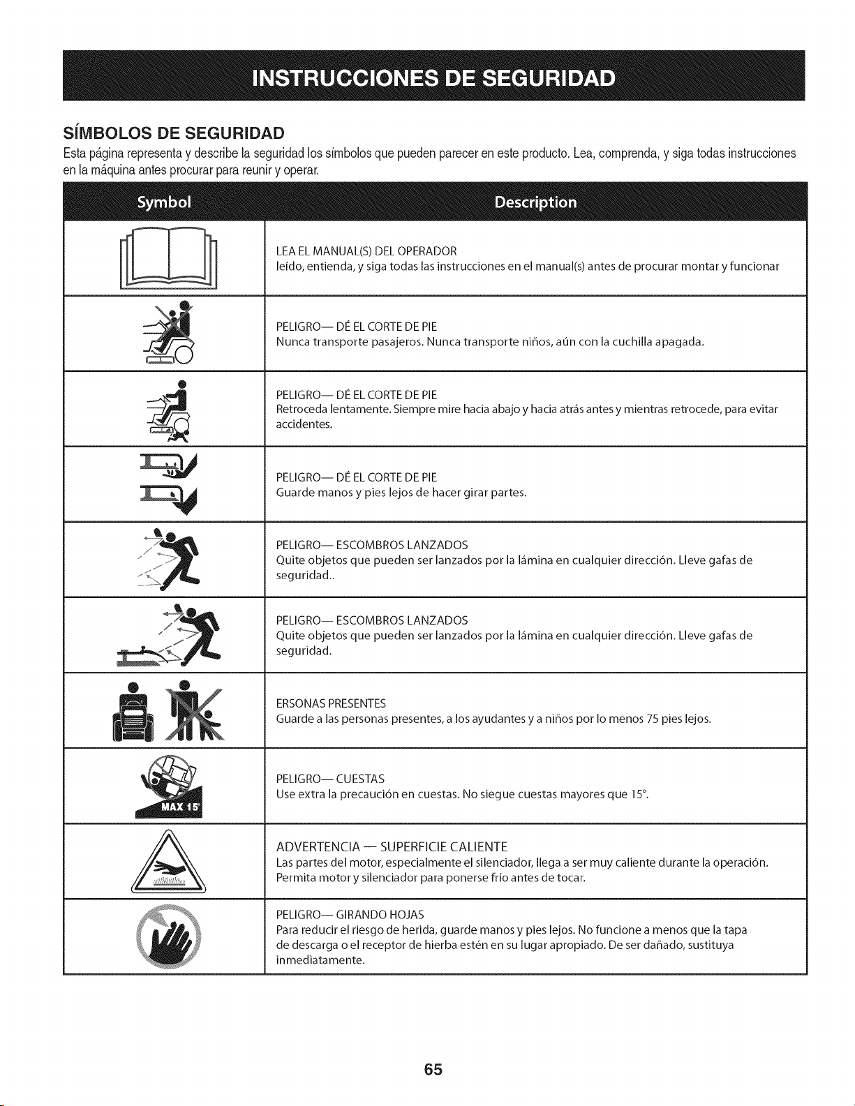
SJlVlBOLOS DE SEGURIDAD
Estap&ginarepresentay describela seguridadlos simbolosquepuedenpareceren este producto.Lea,comprenda,y sigatodasinstrucciones
enla m_quinaantesprocurarpara reuniry operar.
0
AL
LEA EL MANUAL(S) DEL OPERADOR
leido, entienda, y siga todas las instrucciones en el manual(s) antes de procurar montar y funcionar
PELIGRO-- DE EL CORTE DE PIE
Nunca transporte pasajeros. Nunca transporte ni_os, aun con la cuchilla apagada.
PELIGRO-- DE EL CORTE DE PIE
Retroceda lentamente. Siempre mire hacia abajo y hacia atr_is antes y mientras retrocede, para evitar
accidentes.
PELIGRO-- DE EL CORTE DE PIE
Guarde manos y pies lejos de hacer girar partes.
PELIGRO-- ESCOMBROS LANZADOS
Quite objetos que pueden ser lanzados pot la I_imina en cualquier direcci6n. Lleve gafas de
seguridad..
PELIGRO-- ESCOMBROS LANZADOS
Quite objetos que pueden ser lanzados pot la I_imina en cualquier direcci6n. Lleve gafas de
seguridad.
ERSONAS PRESENTES
Guarde alas personas presentes, a los ayudantes y a ni_os pot Io menos 75 pies lejos.
PELIGRO-- CUESTAS
Use extra la precauci6n en cuestas. No siegue cuestas mayores que 15°.
ADVERTENCIA -- SUPERFICIE CALIENTE
Las partes del motor, especialmente el silenciador, Ilega a set muy caliente durante la operaci6n.
Permita motor y silenciador para ponerse frio antes de tocar.
PELIGRO-- GIRANDO HOJAS
Para reducir el riesgo de herida, guarde manos y pies lejos. No funcione a menos que la tapa
de descarga o el receptor de hierba est_n en su lugar apropiado. De ser dahado, sustituya
inmediatamente.
65
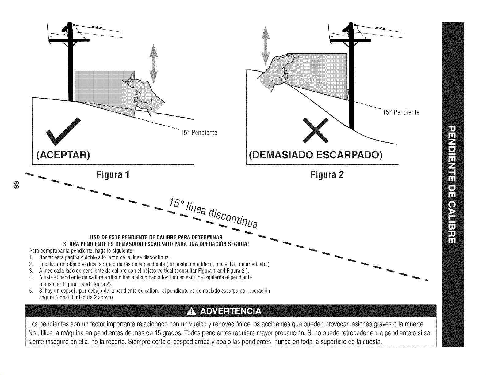
(ACEPTAR)
I5 ° Pendiente
X
(DEMASIADO ESCARPADO)
15° Pendiente
• Figura1
"'"
USO DE ESTE PENDiENTE DE CALIBRE PARA DETERrvIINAR
SlUNA PENDIENTEES DEIVlASIADOESCARPADO PARA UNA OPEBACION SEGURA!
Para comprobar la pendiente, haga Io siguiente:
1. Borrar esta p_ginay doble a Io largo de la linea discontinua.
2.
3.
4.
5,
Localizar un objeto vertical sobre o detr_.sde la pendiente (un poste, un edificio, una valla, un _.rbol,etc.)
Alinee cada lado de pendiente de calibre con el objeto vertical (consultar Figura 1 and Figura 2 ).
Ajuste el pendiente de calibre arriba o hacia abajo hasta los toques esquina izquierda el pendiente
(consultar Figura 1 and Figura 2).
Si hay un espacio por debajo de la pendiente de calibre, el pendiente es demasiado escarpa por operaci6n
segura (consultar Figura 2 above).
Figura 2
Las pendientes son un factor importante relacionado con un vuelco y renovaci6nde los accidentes que pueden provocar lesiones graves o la muerte.
No utilice la ma.quinaen pendientesde ma.sde 15 grados. Todos pendientes requiere mayor precauci6n. Si no puede retroceder en la pendiente o si se
siente inseguro en ella, no la recorte. Siemprecorte el cesped arriba y abajo las pendientes, nunca en toda la superficie de la cuesta.
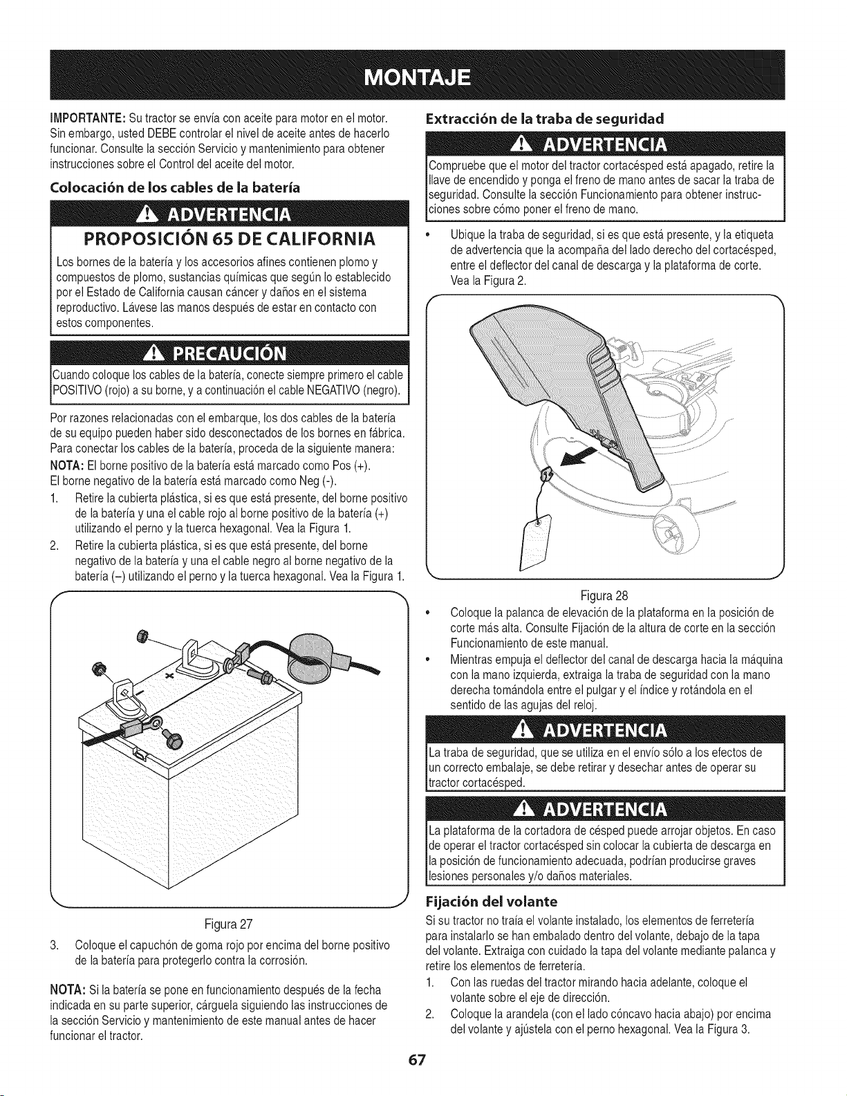
IMPORTANTE: Su tractor se envia con aceite para motor en el motor.
Sin embargo, usted DEBEcontrolar el nivel de aceite antes de hacerlo
funcionar.Consulte la secci6n Servicio y mantenimiento para obtener
instrucciones sobre el Control del aceite del motor.
Colocaci6n de los cables de la bateria
PROPOSICION 65 DE CALIFORNIA
Los bornes de la bateria y los accesorios alines contienen plomo y
compuestos de plomo, sustancias quimicas que segun io establecido
pot ei Estado de California causan cfincer y da_os en el sistema
reproductivo. Lfivese las manos despues de estar en contacto con
estos componentes.
Cuandocoloque los cablesde la bateria,conecte siempre primeroel cable
POSlTIVO(rojo) a su borne,y a continuaci6nel cable NEGATIVO(negro).
Pot razones relacionadas con el embarque, los dos canes de la bateria
de su equipo pueden haber sido desconectados de los bornes en ffibrica.
Para conectar los canes de la bateria, proceda de la siguiente manera:
NOTA: El borne positivo de la bateria estfi marcadocomo Pos (+).
El borne negativo de la bateriaestfi marcadocomo Neg (-).
1. Retire ia cubierta plfistica, si es que estfi presente, del borne positivo
de la bateria y una el cable rojo al borne positivo de la bateria (+)
utilizando el perno y la tuerca hexagonal.Vea la Figura 1.
2. Retire ia cubierta pla.stica,si es que esta.presente, del borne
negativo de la bateria y unael cane negro al borne negativo de la
bateria (-) utilizando el perno y la tuerca hexagonal. Veala Figura 1.
Figura 27
3. Coloque el capuch6n de goma rojo pot encima del borne positivo
de la bateria paraprotegerlo contra la corrosi6n.
NOTA: Si la bateria se pone en funcionamientodespues de la fecha
indicada en su parte superior, cfirguela siguiendo ias instrucciones de
la secci6n Servicio y mantenimientode este manual antes de hacer
funcionar el tractor.
E×tracci6n de la traba de seguridad
Compruebe que el motordel tractor cortacesped estfi apagado, retire la
ilavede encendido y ponga ei freno de manoantes de sacar ia traba de
seguridad. Consulte ia secci6n Funcionamientopara obtener instruc-
lc ones sobre c6mo poner e freno de mano.
• Ubique la traba de seguridad, si es que estfi presente,y ia etiqueta
de advertencia que ia acompa_a del lado derecho del cortacesped,
entre el deflector dei canal de descarga y ia plataforma de corte.
Vea la Figura 2.
/
Figura 28
Coloque la palanca de eievaci6n de ia plataforma en ia posici6n de
corte mils aita. Consulte Fijaci6n de la aitura de corte en la secci6n
Funcionamientode este manual.
Mientras empuja el deflector del canal de descarga hacia la mfiquina
con ia mano izquierda, extraiga la traba de seguridad con la mano
derecha tomfindola entre ei pulgary el indice y rotfindola en el
sentido de las agujas del reloj.
La traba de seguridad, que se utiiiza en el envio s61oa los efectos de
un correcto embalaje, se debe retirar y desechar antes de operar su
tractor cortacesped.
La plataforma de la cortadora de cesped puede arrojar objetos. En caso
de operar ei tractor cortacesped sin colocar ia cubierta de descarga en
la posici6n de funcionamientoadecuada, podrian producirsegraves
I es ones persona es y/o da_os mater a es.
Fijaci6n del volante
Si su tractor no trda el volante instalado, los elementos de ferreteria
para instalarlo se han embaladodentro del volante, debajo de la tapa
del volante. Extraiga con cuidado la tapa del volante mediante palanca y
retire los elementosde ferreteria.
1. Con las ruedas dei tractor mirando haciaadelante, coloque el
volante sobre el eje de direcci6n.
2. Coloque la arandela (con el lado c6ncavo hacia abajo) pot encima
del volante y ajQstelacon el perno hexagonal. Vea la Figura 3.
67
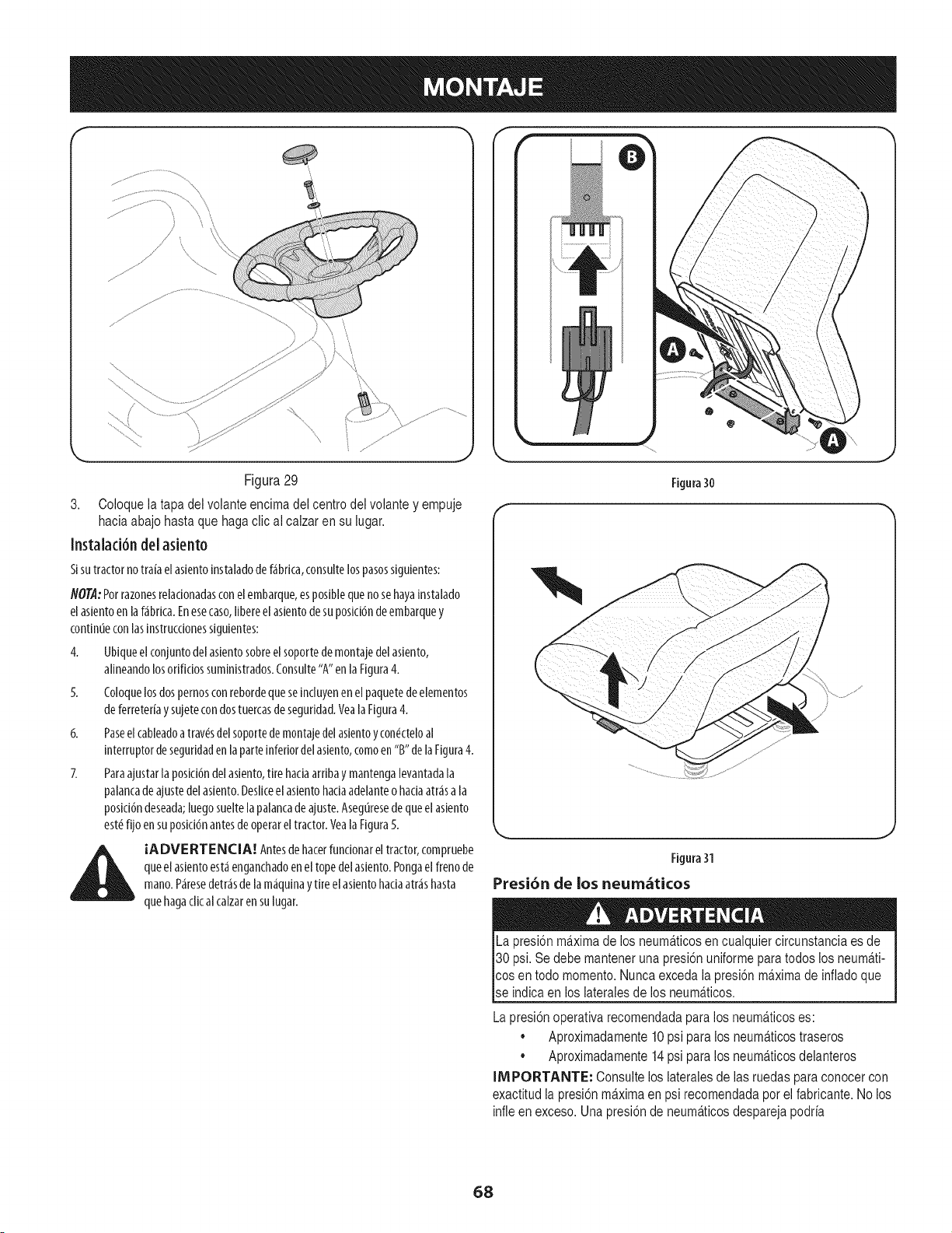
F
Figura29
3. Coloquela tapadelvolanteencimadel centrodelvolantey empuje
haciaabajohastaquehagaclical calzaren sulugar.
Instalad6n del asiento
Sisu tractor no traia el asientoinstalado de f_brica,consulte los pasossiguientes:
NOTA:Por razonesrelacionadasconel embarque,esposibleque no sehayainstalado
el asientoen laf_brica. Enesecaso,libereel asientode su posicidnde embarquey
contin0econlas instruccionessiguientes:
4. Ubiqueel conjunto delasientosobreel soportede montaje del asiento,
alineandolosorificios suministrados.Consulte"A"en la Figura4.
5. Coloquelos dos pernosconrebordeque seincluyenen el paquetedeelementos
de ferreterfay sujetecon dos tuercasde seguridad.VealaFigura 4.
6. Paseel cableadoa trav_sdelsoportedemontaje delasientoycon_cteloal
interruptor deseguridaden la parte inferiordelasiento,comoen"B" de laFigura4.
7. Paraajustar la posid6n del asiento,tire haciaarriba y mantengalevantadala
palancade ajuste delasiento.Desliceel asientohada adelanteo haciaatr_sa la
posici6ndeseada;luego sueltela palancade ajuste.Aseg0resede que el asiento
est_fijo en suposici6nantesde operarel tractor. Veala Figura5.
IADVE RTENCIA! Antesde hacerfuncionar el tractor, compruebe
que el asientoest,1enganchadoenel tope del asiento.Pongael freno de
mano.Paresedetr_sde lam_quina y tire el asientohaciaatr_s hasta
que hagaclic al calzaren sulugar.
Figura30
/
Figura31
Presi6n de los neum_ticos
La presi6n ma.ximade los neuma.ticosen cualquier circunstancia es de
30 psi. Se debe mantener una presi6n uniforme para todos los neuma.ti-
cos en todo momento. Nunca exceda la presi6n ma.ximade inflado que
se indica en los iateraies de los neuma.ticos.
La presi6n operativa recomendada paralos neum_.ticoses:
Aproximadamente 10psi para los neuma.ticostraseros
• Aproximadamente 14psi para los neum_.ticosdelanteros
IMPORTANTE: Consulte los lateralesde ias ruedas para conocer con
exactitud ia presi6nma.ximaen psi recomendada pot el fabricante. No los
infle en exceso. Una presi6nde neuma.ticosdespareja podria
68
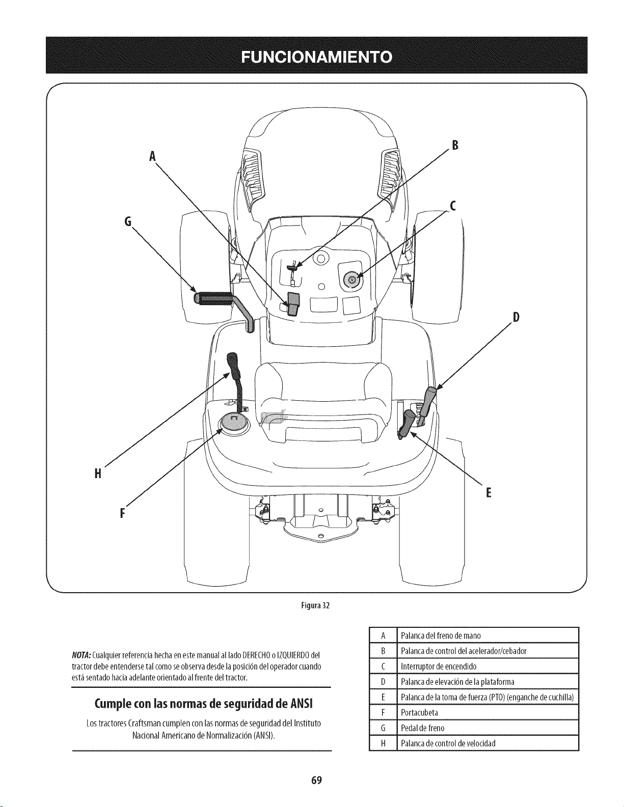
H
A
©
D
Figura 32
NOT,4:Cuaiquierreferendahechaenestemanualai iadoDERECHOo iZQUIERDOdel
tractordebeentendersetalcomoseobservadesdelaposici6ndeloperadorcuando
est_sentadohaciaadelanteorientadoalfrentedeltractor.
Cumpleconlas normas de seguridadde ANSI
LostractoresCraftsmancumplenconlasnormasdeseguridaddelInstituto
NationalAmerkanodeNormalizad6n(ANSI).
A Palancadelfrenode mano
B Palancadecontroldelacelerador/cebador
C Interruptordeencendido
D Palancadeelevaci6ndelaplataforma
E Palancadela tomadefuerza(PTO)(enganchedecuchilla)
F Portacubeta
G Pedaldefreno
H Palancadecontroldeveloddad
69

Frenodemano
Paracolocarelfrenodemano,presionearondoelpedaldefreno.Muevalapalancadel
frenodemanohaciala posici6nON.Suelteelpedaldefrenoparapermitirqueelfreno
demanoengrane.
Parasoltarelfrenodemano,presioneelpedaldefreno,saquelapalancadelfrenode
manodelaposici6nONyll_velaa laposici6nOFF.
NOTA:Sieloperadorabandonaelasientoy dejaelmotorenfuncionamiento,deber_
colocarel frenodemano,oel motorseapagar_deformaautom_tica.
Palancade control del aceleradorlcebador
Lapalancadecontroldelacelerador/cebadorest_ubicadadellado
derechodeltablerodeinstrumentosdeltractor.Estapalancacontrola
lavelocidaddelmotory,cuandoselaempujacompletamentehacia
adelante,tambi_ncontrolaelcebador.CuandoseIocolocaenunaposici6n
determinada,elaceleradormantieneunaveloddaddemotoruniforme.
[M PORTANTE: Cuandoopereeltractorconiapiataformade
cortecolocada,aseguresedequelapalancadelaceleradorest_siempre
enlaposici6nFAST(r_pida;representadaporunaliebre).
Interruptorde encendido
Elinterruptor deencendidoseactiva para arrancarel motor. Insertela
Ilaveen el interruptor de encendidoy gire enel sentido de lasagujas
del reloja la posici6nSTART(arranque).Sueltela Ilaveen laposici6nON
(encendido)una vezque haya arrancadoel motor.
Paradetener el motor, gire la Ilavede encendidoen sentidocontrario a
lasagujasdel reloj hastala posici6nOFF(apagado).YealaFigura 7.
Nuncadeje lam_quinaenfuncionamientosinvigilancia.Cortesiemprela PTO,
muevalapalancadecambiosalaposici6nNeutral(puntomuerto),pongael
frenode mano,pareel motory retirela flare,paraevitarguealguienencienda
accidentalmenteelmotor.
IM PORTANTE: Antesde utilizareltractor,consulteInterruptoresde bloqueode
seguridadyArranquedelmotorenlasecci6nFuncionamientodelpresentemanualpara
obtenerm_sinstruccionesdetalladas.
Encendido
Arranque
Apagado
Figura 33
Nuncadejelam_quinaenfuncionamientosinvigilancia.CortesiemprelaPTO,
muevalapalancadecambiosa laposici6nNeutral(puntomuerto),pongael
frenode mano,pareelmotory retire laflare, paraevitar quealguienencienda
acddentalmenteel motor.
Palancadeajuste dei asiento
Lapalancadeajustedelasientoest_ubicadadelladoizquierdodelasiento.Utilice
estapalancaparaajustarelasientohadaadelanteohadaatr_saunaposid6nde
operad6nc6moda.Veaposteriormentela secd6n"Servidoy mantenimiento"deestas
instrucdonesomanual.
Palancadeelevaci6nde ia plataforma
Ubicadaen el guardabarrosderechodel tractor, lapalancadeelevad6n
de la plataformaseutiliza para cambiarla altura de la plataformade
corte. Parautilizarla, muevala palancahaciala izquierda,luegocol6quela
en la muescaque mejorseadaptea la aplicaci6ndeseada.
Palancadelatomadefuerza(PT0)(enganchedecuchilla)
Ubicadaenelguardabarrosderechodeltractor,lapalancadetomade
fuerza(PT0)(enganchedecuchilla)seutilizaparadaralimentaci6nala
plataformadecorteoaotrosaccesorios(disponiblesporseparado).Para
hacerlafuncionar,muevalapalancatotalmentehaciaadelante.Moviendo
lapalancatotalmentehaciaatr_s,enlaposici6nPTOOFF(tomadefuerza
desconectada),secortalaenergiaa laplataformadecorte/accesorio.
NOTA:AIencenderelmotor,lapalancaPTO(enganchedecuchilla)debe
encontrarseenposici6ndesconectada(PTOOFF).
Portacubeta
Elportacubetadeltractorest_ubicadosobreelguardabarrosala
izquierdadelasiento.
Palancadecontrol deveiocidad
4
ill
Z
m
o
m
Z
m4
La palancade control de velocidad,ubicadasobreel guardabarrostrasero
izquierdo,controla la velocidaddepiso deltractor cortac_spedasicomo la
direcci6n dedesplazamiento.
Paraconducirhaciaadelanteo haciaatr_s,lentamente mueva la palancade control
de velocidada lavelocidaddeseada"F" avanceo "R" marchaatr_s.
Paradetenerse,muevalapalancadecontroldeveloddadalaposid6n"N"neutral.
Paracortar el c_sped,coloquela palancade control de
velocidaden la posici6n"Cutting Speed"(veloddad
de corte) o una veloddadde avaricemenor para
obtener los mejoresresultados.
Nora: No utiliceel pedal defreno paracontrolarla
velocidadde pisodel tractor cortac_sped.Utilice
siemprela palancadecontrol de velocidadpara reducir
la veloddadde pisodeltractor. Sipresionael pedalde
freno conla palancade control de veloddadengranada
como parte dela operaci6nnormalocasionar_el
desgasteprematurode lacorreadetransmisi6n.
IM PORTANTE: No intentecambiar la
direcci6n dedesplazamientomientras eltractor
est_en movimiento. Puedecausardaffosgravesa
la transmisi6ndel tractor. SiempreIleve eltractor a
la detenci6n completaantes de moverla palancade
/
$_ED
_IEVE_E
controldeveloddaddesdelaposici6ndeavancealademarchaatr_soviceversa.
!
7O
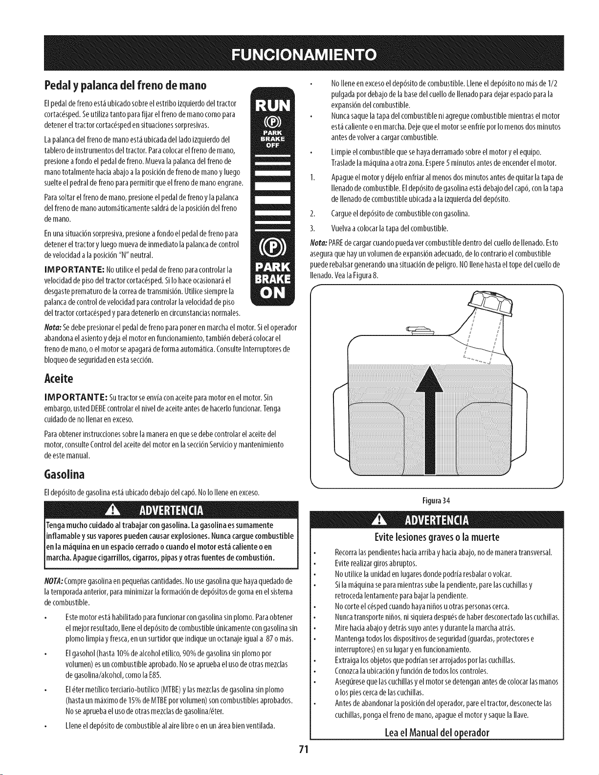
Pedaly palancadei freno demano
Elpedaldefrenoest_ubicadosobreelestdbolzquierdodeltractor
cortac_sped.Seutlllzatantoparafljar elfrenodemanocomopara
detenereltractorcortac_spedensltuadonessorpreslvas.
Lapalancadelfrenodemanoest_ublcadadeilado[zquierdodel
tablerode[nstrumentosdeltractor.Paracolocarelfrenodemano,
preslonearondoelpedaldefreno.Muevaiapalancadelfrenode
manototalmentebadaabajoalaposicl6ndefrenodemanoy luego
suelteelpedraldefrenoparapermltlrqueelfrenodemanoengrane.
Parasoltarelfrenodemano,presioneelpedaldefrenoylapalanca
delfrenodemanoautom_tlcamentesaldr_delaposid6ndelfreno
demano.
Enunasituaci6nsorpresiva,presionearondoelpedaldefrenopara
detenereltractory luegomuevade[nmedlatolapalancadecontrol
develoddada laposid6n"N"neutral.
IM PO RTANTE: Noutlllceelpedaldefrenoparacontrolarla
veloddadde pisodeltractorcortac_sped.S[Iohaceocasionar_el
desgasteprematurodelacorreadetransmlsi6n.Utlllcesiemprela
palancadecontroldeveloddadparacontrolarlaveloddadde piso
deltractorcortac_spedyparadetenerloendrcunstandasnormales.
h'ota:Sedebepreslonarelpedaldefrenoparaponerenmarchael motor.S[el operador
abandonaelasientoy dejaelmotorenfuncionamiento,tambi_ndeber_colocarel
frenodemano,oelmotorseapagar_deformaautom_tica.Consultelnterruptoresde
bloqueodesegurldadenestasecd6n.
Aceite
[MPORTANTE: Sutractorseenviaconaceiteparamotorenelmotor.Sin
embargo,ustedDEBEcontrolarelnlveldeacelteantesde hacerlofundonar.Tenga
culdadodenollenarenexceso.
Paraobtener[nstruccionessobrelamaneraenquesedebecontrolarel aceltedel
motor,consulteControldelaceltedelmotorenla secd6nServldoy mantenlmlento
deestemanual.
Gasolina
Eldep6sitodegasolinaest,1ubicadodebajodelcap&NoIoIleneenexceso.
Tengamuchocuidadoal trabajarcongasolina.Lagasolinaessumamente
inflamabley susvaporespuedencausarexplosiones.Nuncacarguecombustible
enla m_quinaen un espadocerradoo cuandoelmotorest_calienteo en
march&Apaguec garr os,cgarros,p pasy otrasfuentesdecombust6n.
flOTA:Compregasolinaen pequeffascantidades.No usegasolinaque hayaquedadode
la temporadaanterior, para mlnlmlzar laformad6n de dep6sitosdegoma en elslstema
de combustible.
Estemotor est_ habilitado para funcionarcongasolinasin plomo. Paraobtener
el mejor resultado,Ilene eldep6slto decombustible unicamentecongasollnasin
plomo Ilmplay fresca,en un surtldor que [ndique un octanaje[guala 87 o m_s.
Elgasohol (hasta10%de alcoholet[lico,90% de gasolina sin plomo por
volumen)esun combustibleaprobado.Noseapruebael usode otrasmezclas
de gasollna/alcohol,como la E85.
El_ter met[licoterdado-but[Iko (MTBE)y las mezclasdegasollna sin plomo
(hastaun m_ximo de 15%de MTBEpot volumen) soncombustiblesaprobados.
Noseapruebael usode otrasmezclasde gasollna/_ter.
Lleneel dep6sitode combustibleal alre Ilbreo en un_ireablenventllada.
NoIleneenexcesoeldep6sitodecombustible.Lleneeldep6sitonom_sde1/2
pulgadapordebajodelabasedelcuellode Ilenadoparadejarespadoparala
expansl6ndelcombustible.
Nuncasaquelatapadelcombustiblen[agreguecombustiblemientraselmotor
est,1callenteoenmarcha.DejequeelmotorseenfrieporIomenosdosmlnutos
antesdevolveracargarcombustible.
Limpleelcombustiblequesehayaderramadosobreelmotory elequlpo.
Trasladela m_qulnaaotrazona.Espere5mlnutosantesdeencenderelmotor.
1. Apagueelmotory d_jeloenfriaralmenosdosmlnutosantesdequltarlatapade
Ilenadodecombustible.Eldep6sitodegasollnaest,1debajodelcap6,conlatapa
deIlenadodecombustibleublcadaalalzqulerdadeldep6slto.
2. Cargueeldep6sltodecombustiblecongasollna.
3. Vuelvaacolocarlatapadelcombustible.
/Vota:PAREdecargarcuandopuedavercombustibledentrodelcuellodeIlenado.Esto
aseguraquehayunvolumendeexpansi6nadecuado,deIocontrarioelcombustible
puederebalsargenerandounasltuad6ndepeligro.NOIlenehastaeltopedelcuellode
Ilenado.YealaFigura8.
Figura34
Evitelesiones graveso la muerte
Recorralaspendlenteshaciaarrlbay badaabajo,nodemaneratransversal.
Eviterealizargirosabruptos.
Noutilicelaunidadenlugaresdondepodr[aresbalarovolcar.
Silamaquinaseparamientrassubelapendiente,parelascuchillasy
retrocedalentamenteparabajarlapendiente.
Nocorteelc_spedcuandohayaniffosuotraspersonascerca.
Nuncatransporteni_os,n[siquieradespu_sdehaberdesconectadolascuchillas.
Mirehaciaabajoydetr_ssuyoantesy durantelamarchaatr_s.
Mantengatodoslosdispositivosdeseguridad(guardas,protectorese
interruptores)ensulugaryenfuncionamiento.
Extraigalosobjetosquepodr[anserarrojadosporlascuchillas.
Conozcalaubicaci6ny fund6ndetodosloscontroles.
Aseguresequelascuchillasy elmotorsedetenganantesdecolocarlasmanos
olospiescercadelascuchillas.
Antesdeabandonarlaposici6ndeloperador,pareeltractor,desconectelas
cuchillas,pongaelfrenodemano,apagueelmotory saquela Ilave.
lea el Manual del o erador
71
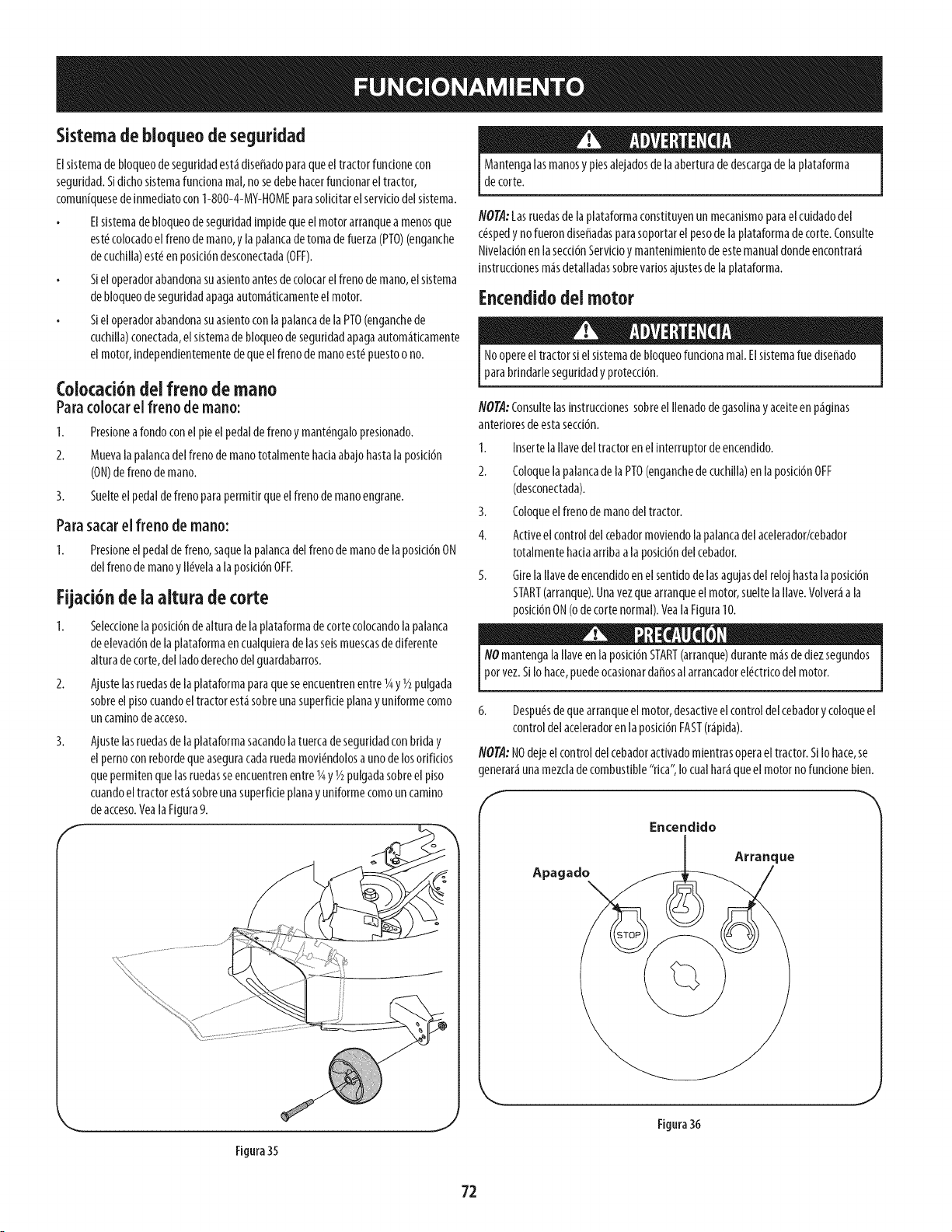
Sistema de bloqueo de seguridad
Elsistemadebloqueodeseguridadest_diseffadoparaqueel tractorfuncionecon
seguridad.Sidichosistemafundonamal,nosedebehacerfundonarel tractor,
comun[quesedeinmediatocon1-800-4-MY-HOMEparasolicitarelserviciodelsistema.
Elsistemadebloqueodeseguridadimpidequeelmotorarranquea menosque
est_colocadoelfrenodemano,y lapalancadetomadefuerza(PTO)(enganche
decuchilla)est_enposici6ndesconectada(OFF).
Sieloperadorabandonasuasientoantesdecolocarelfrenodemano,elsistema
debloqueodeseguridadapagaautom_ticamenteelmotor.
SieloperadorabandonasuasientoconlapalancadelaPTO(enganchede
cuchilla)conectada,elsistemadebloqueodeseguridadapagaautom_ticamente
elmotor,independientementedequeelfrenodemanoest_puestoono.
Colocaci6ndel freno de mano
Paracolocarel freno de mano:
I. Presioneafondoconelpieelpedaldefrenoymant_ngalopresionado.
2. Muevala palancadelfrenodemanototalmentehaciaabajohastalaposici6n
(ON)defrenodemano.
3.
Para
I.
Suelteelpedaldefrenoparapermitirqueelfrenodemanoengrane.
sacarel freno de mano:
Presioneelpedaldefreno,saquelapalancadelfrenodemanodelaposici6nON
delfrenodemanoy ll_velaa laposici6nOFF.
Fijaci6ndeia aitura decorte
I. Seleccioneiaposici6ndealturadeiapiataformadecortecolocandoiapaianca
deelevaci6ndelaplataformaencualquieradelasseismuescasdediferente
alturadecorte,delladoderechodelguardabarros.
2. Ajustelasruedasdelaplataformaparaqueseencuentrenentreigy i/2pulgada
sobreelpisocuandoeltractorestasobreunasuperficieplanay uniformecomo
uncaminodeacceso.
3.
Ajustelasruedasdelaplataformasacandolatuercadeseguddadconbdday
elpernoconrebordequeaseguracadaruedamovi_ndolosaunodelosorificios
quepermitenquelasruedasseencuentrenentreigy i/2pulgadasobreelpiso
cuandoeltractorest_sobreunasuperficieplanay uniformecomouncamino
deacceso.VealaFigura9.
Mantengalasmanosy piesalejadosdelaaberturadedescargadelaplataforma
decorte.
NOTA:Lasruedasdelaplataformaconstituyenun mecanismoparaelcuidadodel
c_spedy nofuerondiseffadasparasoportarel pesodelaplataformadecorte.Consulte
Nivelaci6nenlasecci6nServidoymantenimientodeestemanualdondeencontrar_
instruccionesm_sdetalladassobrevariosajustesde laplataforma.
Encendidodei motor
Noopereeltractorsielsistemadebloqueofuncionareal.Elsistemaruediseffado
parabrindarleseguridadyprotecci6n.
NOTA:ConsultelasinstrucdonessobreelIlenadodegasolinay aceiteenp_ginas
anterioresdeestasecci6n.
1. InsertelaIlavedel tractor enel interruptor deencendido.
2. Coloquela palancade la PTO(enganchede cuchilla)en la posici6nOFF
(desconectada).
3. Coloqueelfreno de manodel tractor.
4. Active el control del cebadormoviendola palancadel acelerador/cebador
totalmente haciaarriba a la posici6ndelcebador.
5. Gire la Ilavedeencendido enel sentido de lasagujasdel reloj hastala posici6n
START(arranque).Unavez quearranque el motor,suelte la Ilave.Volver_a la
posici6nON(o decorte normal). Yeala Figura10.
NOmantenga la Ilaveen la posici6nSTART(arranque)durante m_sde diezsegundos
por vez.Si Io hace,puedeocasionardaffosal arrancadorel_ctricodelmotor.
6. Despu_sde que arranqueel motor, desactiveel control delcebadorycoloqueel
control delaceleradoren la posicl6nFAST(r_pida).
NOTA:NOdejeel control del cebadoractivado mientrasopera el tractor. Si Io hace,se
generar_ unamezclade combustible "rica", Io cual har_que el motor no funcione bien.
Encendido
Arranque
Apagado
Figura 35
Figura36
72
Detenci6n del motor
Sigolpeacontraalgunobjetoextraffo,detengaelmotor,desconecteel(los)cable(s)de
labujiayconecteel motora masa.lnspeccioneminuciosamentelam_quinaparaversi
est&daffada.Repareel daffoantesdevolveraencenderelmotory operarlam_quina.
I. Silascuchillasest_nenganchadas,coloquela palancadelaPTO(enganchede
cuchilla)enlaposici6nOFF(desconectada).
2. Girelallavedeencendidoensentidocontrarioalasagujasdelreloja laposici6n
STOP(parar).
3. Retirelallavedelinterruptordeencendidoparaevitarquealguienencienda
accidentalmenteelmotor.
Conducd6ndel tractor
Evitearrancarsubitamente,desarrollarexcesivavelocidadydetenersederepente.
NoabandoneelasientodeltractorsincolocarprimerolaPTO(enganchedecuchilla)
enlaposici6nOFF(desconectada),presionarel pedaldelfrenoy colocarel frenode
mano.Sidejaeltractorsinvlgilancla,apagueelmotory retirelaIlavedeencendldo.
Siempremirehaciaabajoy haciaatr_santesy mientrassedespiazamarchaatr_s,
paraevitarunaccidente.
1. Muevala palancadel aceleradora laposici6nFAST(Rh,PIDA,representadapor
una liebre).
NOTA:Slemprehagafunclonar el tractor conla palancadel acelerador/cebador
en la posici6nFAST(liebre),para un usom_seficazde la plataforma de corteo
de otrosaccesorios(disponiblespor separado).
2. Suelteel freno de manopresionandoel pedal de freno.
3. Muevalentamente la palancade control de velocldada la posicl6ndeseada,"F"
avanceo"R" marcha atr_s.Cuantom_ssemuevala palancahaciaadelante o
haclaatr_s,m_sr_pidosemover_eltractor.
NOintente cambiarla dlreccl6nde desplazamlentomientrasel tractor est_en
movlmiento. SiempreIleveel tractor a ladetend6n completaantesde moverla
palancade control de veloddad desdela poslcl6ndeavaricea la de marchaatr_s o
vlceversa.De no hacerlosepuedenproduclr daffosgravesa latransmlsl6n del tractor.
IMPORTANTE:Quienesutilicen la m_quinapor primeravez debeusarvelocidadesm_s
bajas.Familiarkesepor completoconel funclonamlentoy los controlesdeltractor antes
de operarel tractor a unavelocldadm_s alta.
4. Paradetenerse,muevala palancade controlde velocidada laposid6n"N" neutral.
IM PO RTANTE: Enuna situacl6nsorpresiva,preslonea rondo el pedal de ffeno
para detenerel tractor y luegomuevade [nmedlatola palancade control de velocldad
a la posici6n"N" neutral.
5. Coloqueelfrenodemanopresionandoafondoelpedaldefrenoy mantenidndolo
presionadomientrascolocalapalancadelfrenodemanoenlaposici6nON.Suelte
elpedaldefrenoparapermitirqueelfrenodemanoengrane.
Antesdeabandonarlaposici6ndeloperadorporcualquiermotivo,desenganchelas
cuchillas,coloquelapalancadecontroldevelocidaden neutral,coloqueelfrenode
mano,apagueelmotory retirelaIlave.
IMPORTANTE:Siempreque detengaeltractor pot cualquier raz6nen un _rea dec_sped,
hagaIoslgulente:
1. Coloquela palancade control de velocldaden N (neutral),
2. Coloqueel freno de mano,
3. Apagueel motor y retire la Ilave.
Esopermitir_ reduciral minimo la posibilidadde que suc_spedresulte"quemado" por
el escapecallente del motor en funclonamlento.
Operaci6nenpendiente
Consulteel INDICADORDEPENDIENTESen lasecci6nNormasde seguridadimportantes
del manual para contribuir a determinar en qu_pendientespuedeoperar el tractor con
seguridad.
Nocorteenpendientesconunainclinaci6ndem_sde15° (elevaci6naproximadade2
1/2piesporcada10pies).Eltractorpodriavoltearsey causarlesionesseveras.
Enpendientes,el c_speddebecortarseensentidoascendentey descendente,
NUNCAtransversal.
Tengamuchocuidadoal cambiarde direcci6nen una pendiente.
Est_atento a los hoyos,surcos,baches,rocasu otrosobjetos ocultos. Elterreno
desnlveladopuedevoltear lam_qulna. Elc_spedalto puedeocultar obst_culos.
Evltereallzar giros cuandoopereen una pendlente. Sideberealizar un giro,
h_galo pendlente abajo.Sublruna pendlenteaumentaenormementelas
posibllldadesdeque el vehiculod_ una vueltade campana.
Evitedetenersecuandosubauna pendlente.Sifuesenecesariodetenerse
mientras sube unapendlente, arranquesuavey culdadosamentepara reducirla
poslbllldad de que el tractor sed_ vuelta haclaatr_s.
Enganchede las cuchiilas
AiconectarlaPTO(enganchedecuchilla)sesuministraenergiaalaplataformadecorteoa
otrosaccesorlos(dlsponlblesporseparado).Paraconectarlascuchlllas,hagaloslgulente:
I. Muevalapalancadecontroldelacelerador/cebadorala posici6nFAST(R_,PIDA,
representadaporunaliebre).
2. Tomela palancadelaPTO(enganchedecuchilla)y girelatotalmentehacia
adelantealaposici6nON(enganchada).
3. Mantengalapalancadelaceleradoren laposici6nFAST(liebre),paraunusom_s
eficazdelaplataformadecorteuotrosaccesorios(disponiblesporseparado).
IMPORTANTE:Enelmododeprecaud6nenmarchaatr_selmotorseapagar_
autom_ticamentesiseenganchaelPTOconlapalancadecontroldevelocidaden
posici6nmarchaatr_sconlaIlavedeencendldoenlaposici6ndeCORTENORMAL.
IJsode la palanca de elevad6n de la plataforma
Paraelevar laplataforma de corte,mueva lapalancadeeievaci6nde la plataforma
hacialaizquierday col6quelaen la muescaquemejor seadaptea laaplicaci6n deseada.
ConsulteAjustede la altura de corteanterlormente en esta mlsmaseccl6n.
73
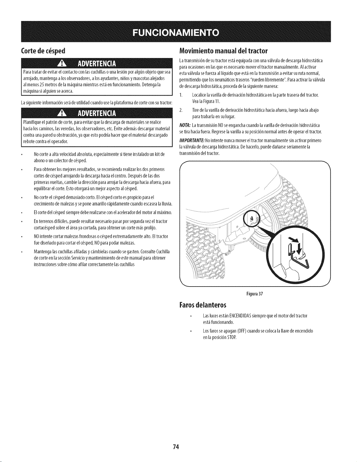
Cortedec sped
Paratratardeevitarelcontactoconlascuch[llaso unalesi6nporalgOnobjetoquesea
arrojado,mantengaalosobservadores,alosayudantes,ni_osymascotasaleiados
almenos25metrosdelam_quinamientrasest_enfuncionamiento.Detengala
m_quinas[alcjuienseacerca.
Lasiguienteinformaci6nser_deutilidadcuandouselaplataformadecorteconsutractor:
Planifiqueelpatr6ndecorte,paraevitarqueladescargadematerlalesserealice
hadaloscaminos,lasveredas,losobservadores,etc.Eviteadem_sdescargarmaterial
contraunapareduobstrucd6n,yaqueestopodriahacerqueelmaterialdescargado
rebotecontraeloperador.
Nocorteaaltavelocidadabsoluta,especialmentesitieneinstaladounkitde
abonoouncolectordec_sped.
Paraobtenerlosmejoresresultados,serecomiendarealizarlosdosprimeros
cortesdec_spedarrojandoladescargahadaelcentro.Despu_sdelasdos
primerasvueltas,cambieladirecci6nparaarrojarladescargahaciaafuera,para
equilibrarelcorte.Estootorgar_un mejoraspectoalc_sped.
Nocorteelc_speddemasiadocorto.Elc_spedcortoespropicioparael
crecimientodemalezasyseponeamarillor@idamentecuandoescasealalluvia.
Elcortedelc_spedsiempredeberealizarseconelaceleradordelmotoralm_ximo.
Enterrenosd[fk[les,puederesultarnecesar[opasarporsegundavezeltractor
cortac_spedsobreel_reayacortada,paraobteneruncortem_sprolljo.
NO[ntentecortarmalezasfrondosasoc_spedextremadamentealto.Eltractor
ruedlseffadoparacortarelc_sped,NOparapodarmalezas.
Mantengalascuchillasafiladasy c_mbielascuandosegasten.ConsulteCuchilla
decorteenlasecd6nServic[oymantenlmlentodeestemanualparaobtener
[nstrucc[onessobrec6moafllarcorrectamentelascuchlllas
Movimiento manual deitractor
La transmisi6nde sutractor est_equipadacon unav_lvula de descargahidrost_tica
para ocaslonesen las queesnecesar[omoverel tractor manualmente.AI actlvar
estav_lvula sefuerzaal I[quldo que est_en la transmlsi6na evltar suruta normal,
permlt[endo quelos neum_tlcostraseros"ruedenIlbremente". Paraactlvar la v_lvula
de descargahldrost_tlca, procedade laslgulente manera:
1. Locallcela varllla de derlvac[6nhldrost_tlcaen laparte traseradel tractor.
YealaFigura 11.
2. Tire de lavarllla de derlvac[6nhldrost_tlca hac[aafuera, luego hac[aabajo
paratrabarla en sulugar.
flOTA: Latransmlsl6n NOseenganchacuandola var[llade derlvad6n hldrost_tlca
setlra hac[afuera. Regresela varlllaa suposic[6nnormal antesde operar el tractor.
IMPORTAflTE:No[ntente nunca movereltractor manualmentesin activar prlmero
la v_lvula de descargahldrost_tica.De hacerlo,puededaffarseser[amentela
transmls[6ndeltractor.
/
Figura37
Farosdelanteros
Laslucesest_nENCENDIDASsiemprequeel motordeltractor
est_fundonando.
Losfarosseapagan(OFF)cuandosecolocalaIlavedeencendido
enlaposici6nSTOP.
74
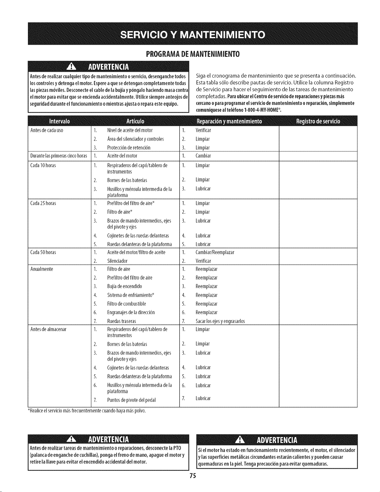
PROGRAMADEMANTENIMIENTO
Antesdereaiizarcuaiquiertipo demantenimientooservicio,desenganchetodos
loscontroiesy detengaelmotor.Espereaquesedetengancompietamentetodas
laspiezasm6viies.Desconecteelcabledela bujiay p6ngalohaciendomasacontra
elmotorparaevitarqueseenciendaaccidentaimente.Utiiicesiempreanteojosde
seguridadduranteelfuncionamientoomientrasajustao reparaesteequipo.
Antesdecadauso
Durantelaspdmerascincohoras
Cada10horas
Cada25horas
Cada50horas
Anualmente
Antesdealmacenar
I. Niveldeaceitedelmotor
2. Areadelsilendadorycontroles
3. Protecd6nderetenci6n
1. Aceitedelmotor
I. Respiraderosdelcap6/tablerode
instrumentos
2. Bornesdelasbaterias
3. Husillosy m_nsulaintermediadela
plataforma
1. Prefiltrodelfiltrodeaires
2. Filtrodeaires
3. Brazosdemandointermedios,ejes
delpivotey ejes
4. Cojinetesdelasruedasdelanteras
S. Ruedasdelanterasdelaplataforma
1. Aceitedelmotor/filtrodeaceite
2. Silenciador
1. Filtrodeaire
2. Prefiltrodelfiltrodeaire
3. Bujiadeencendido
4. Sistemadeenfriamiento*
5. Filtrodecombustible
6. Engranajesde ladirecci6n
Z Ruedastraseras
I. Respiraderosdelcap6/tablerode
instrumentos
2. gornesdelasbaterias
3. grazosdemandointermedios,ejes
delpivotey ejes
4. Cojinetesdelasruedasdelanteras
S. Ruedasdelanterasdelaplataforma
6. Husillosy m_nsulaintermediadela
plataforma
7. Puntosdepivotedelpedal
_Realiceel servic[om_sffecuentementecuandohayam_spolvo.
Siga el cronograma de mantenimiento que se presenta a continuaci6n.
Estatabla s61odescribe pautas de servicio. Utilice la columna Registro
de Servicio para hacerel seguimiento de lastareas de mantenimiento
completadas. ParaubicarelCentrodeserviciode reparacionesy piezasre;is
cercanooparaprogramarel servidode mantenimientoo reparaci6n,simplemente
comuniquesealtel_fono1-800-4-MY-HOME_o
1. Verificar
2. Limpiar
3. Limpiar
1. Cambiar
1. Limpiar
2.
3.
1.
2.
3.
4.
5.
1.
2.
1.
2.
3.
4.
5.
6.
7.
1.
2.
3.
4.
5.
6.
Limpiar
Lubricar
Limpiar
Limpiar
Lubricar
Lubricar
Lubricar
Cambiar/Reemplazar
Verificar
Reemplazar
Reemplazar
Reemplazar
Reemplazar
Reemplazar
Reemplazar
Sacarlosejesy engrasarlos
Limpiar
Limpiar
Lubricar
Lubricar
Lubricar
Lubricar
Lubricar
Antesde realizartareasdemantenimientoo reparaciones,desconectelaPTO
(palancade enganchedecuchillas),pongaelfrenodemano,apagueel motory
retirelaflare paraevitarel encendidoaccidentaldel motor.
Siel motorhaestadoenfuncionamientorecientemente,el motor,el silenciador
y lassuperficiesmet_licascircundantesestar_ncalientesy puedencausar
[quemadurasen a pe .Tengaprecauc6n paraevtar quemaduras.
7S
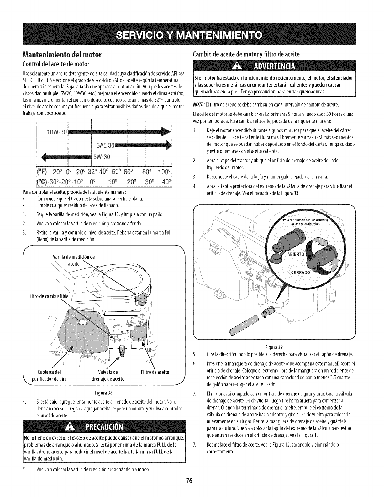
Mantenimiento del motor
Controldelaceitedemotor
Usesolamente un aceitedetergentede aita calidadcuyaclasificaci6nde servicioAPIsea
SF,SG,SHo SJ.Selecdoneel grado de viscosidadSAEdel aceitesegunla temperatura
de operad6nesperada.Sigalatabla que aparecea continuad6n. Aunque losaceitesde
viscosidadmultiple (5W20,I0W30, etc.)mejoranel encendidocuando elclima estafrio,
los mismosincrementanel consumode aceitecuandoseusana masde 32°F.Controle
el nivelde aceiteconmayorfrecuenda paraevitar posiblesda_osdebido a queel motor
trabajacon pocoaceite.
10W_30mmm=====mm==mm__/=m=
SAE30
' l
_ _ m =ill= 5W30
L
(°F) -20o 0° 200 320 40o 500 60o 80o 100°
0° 10° 20o 30o 40o
Paracontrolar elaceite, procedade lasiguiente manera:
Compruebeque el tractor estasobreuna superficie plana.
Limpiecualquierresiduo del area de Ilenado.
1. Saquelavarilla de medici6n,veala Figura12,y limpiela con un paso.
2. Vuelvaa colocarlavarilla de medici6n y presionea rondo.
3. Retirela varillay controle el nivelde aceite.Deberiaestar en la marcaFull
(lleno)de lavarilla de medici6n.
Cambiode aceitede motor y filtro de aceite
Siel motor ha estado en funcionamiento recientemente, el motor, el silenciador
y las superficies met_licas circundantes estar_n calientes y pueden causar
[quemaduras en a p e. Tengaprecauc 6n para ev tar quemaduras.
NOTA:Elfiltro de aceitesedebecambiaren cada intervalo decambio de aceite.
Elaceitedel motor sedebecambiar en lasprimeras5 horasy luegocada50 horaso una
vez por temporada.Paracambiarel aceite,procedade lasiguiente manera:
1. Dejeel motor encendidodurante algunosminutos para queel aceitedel carter
secaliente. Elaceite calientefluira maslibremente yarrastraramassedimentos
del motor quesepuedanhaberdepositadoen el rondodel carter.Tengacuidado
y evite quemarseconel aceitecaliente.
2. Abra el cap6del tractor y ubique el orifido de drenajede aceitedel lado
izquierdodel motor.
3. Desconecteelcable dela bujia y mant_ngaloalejado dela misma.
4. Abra latapita protectoradel extremo de lavalvula dedrenaje paravisualizarel
orifido de drenaje.Veael recuadrode laFigura13.
Varilla de medici6n de
aceite
Filtro de combustible ;
/ ?
/
/
/
4.
/ i
Cubiertadel V_Ivulade Filtro de aceite
purificador de aire drenaje de aceite
J
Figura 38
Siestabajo, agreguelentamente aceiteal Ilenadodeaceite delmotor. No Io
Ileneen exceso.Luegode agregaraceite,espereun minuto yvuelvaa controlar
el nivelde aceite.
NoIo lleneen exceso.Elexcesodeaceitepuedecausarqueelmotorno arranque,
problemasde arranqueoahumado.Siest_porendmadela marcaFULLde la
varilla,dreneaceiteparareducirel niveldeaceitehastalamarcaFULLdela
varilla demedici6n.
Figura39
5. Gire ladirecci6n todo Io posible a laderechaparavisualizar eltap6n de drenaje.
6. Presionela manquerade drenajede aceite (queacompaffaeste manual) sobreel
orificio de drenaje.Coloqueel extremo libre dela mangueraen un recipientede
recolecci6nde aceiteadecuadoconunacapacidadde pot Io menos2.5 cuartos
de gal6n para recogerel aceiteusado.
7. Elmotor esta equipadoconun orificio de drenajede girar y tirar. Girela valvula
de drenaje de aceite1/4de vuelta, luego tire hada afuerapara comenzara
drenar.Cuandohaterminado de drenarel aceite,empuje el extremode la
valvula de drenajede aceite hadaadentro y girela 1/4de vuelta para colocarla
nuevamenteen sulugar.Retire lamanguerade drenajede aceiteyguardela
parausofuturo. Vuelvaa colocarlatapita delextremo de lavalvula para evitar
que entren residuosen el orifido de drenaje.Yeala Figura13.
7. Reemplaceel filtro de aceite,vealaFigura 12,sacandoloy eliminandolo
correctamente.
5. Vuelvaacolocarlavarillademedid6npresionandolaarondo.
76
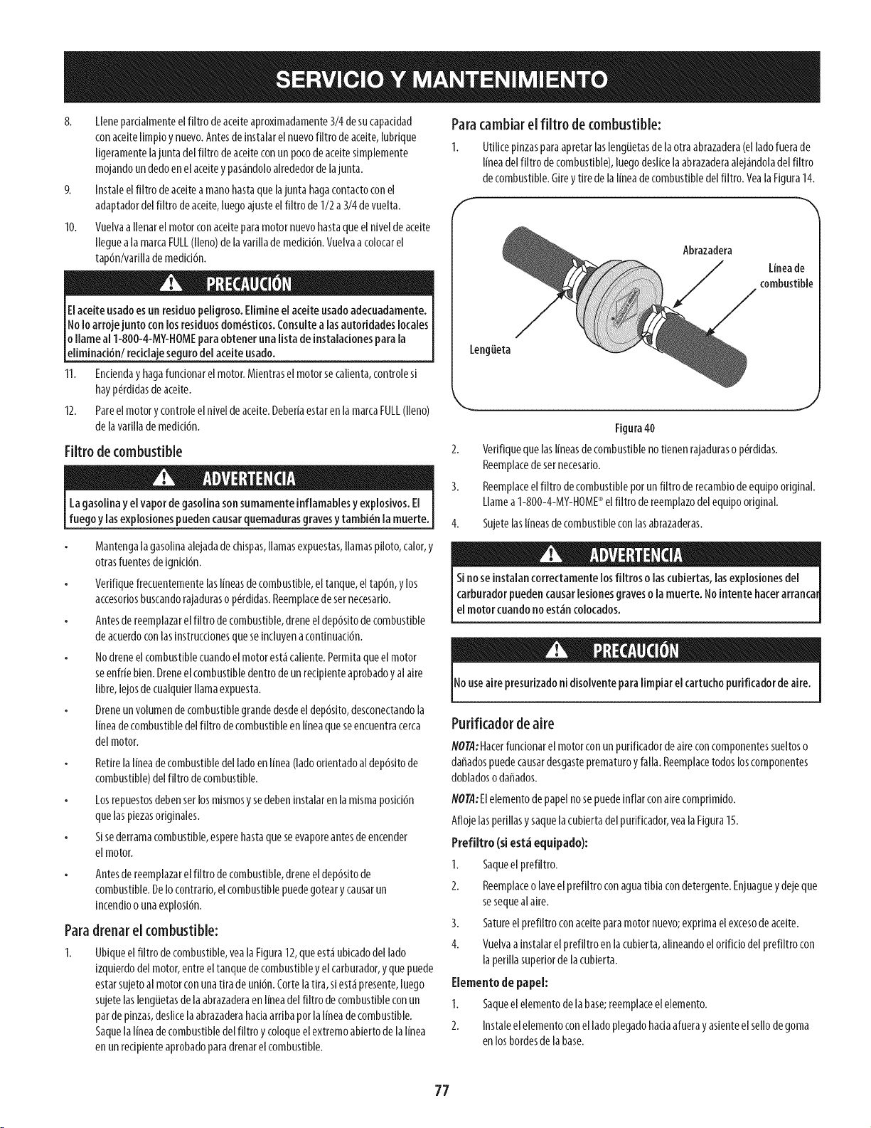
8. Llenepardalmenteelffltrodeaceiteaproximadamente3/4desucapaddad
conaceitelimpioynuevo.Antesde instalarelnuevofiltro deaceite,lubrique
ligeramentelajuntadelffltrodeaceiteconunpocodeaceitesimplemente
mojandoundedoenelaceitey pas_ndoloalrededordelajunta.
9. Instaleelfiltro deacelteamanohastaquelajuntahagacontactoconel
adaptadordelfiltro deaceite,luegoajusteel filtrodeI/2 a3/4devuelta.
10. Vuelvaallenarel motorconacelteparamotornuevohastaqueelnlveldeacelte
lleguealamarcaFULL(lleno)delavarlllademedld6n.Vuelvaacolocarel
tap6n/varillademedid6n.
Elaceiteusadoesun residuopeligroso.Elimineel aceiteusadoadecuadamente.
NoIo arrojejunto conlosresiduosdom_stkos.Consultealasautoridadeslocales
o flameal1-800-4-M¥-HOMEparaobtenerunalistade instaladonesparala
eliminad6nl reddaje segurodelaceiteusado.
11. Encienday hagafuncionarelmotor.Mientraselmotorsecalienta,controles[
hayp_rdidasdeaceite.
12. Pareelmotory controleel niveldeaceite.DeberfaestarenlamarcaFULL(lleno)
delavarfllademedid6n.
Filtro decombustible
Lagasolinay elvapordegasolinasonsumamenteinflamablesy explosivos.El
fuegoy lasexplosionespuedencausarquemadurasgravesy tambi_nlamuerte.
Para
I.
Mantengalagasollnaalejadadechlspas,llamasexpuestas,llamaspfloto,calor,y
otrasfuentesdeignici6n.
Verifiquefrecuentementelaslineasdecombustible,eltanque,el tap6n,y los
accesoriosbuscandorajaduraso p_rdidas.Reemplacedesernecesario.
Antesdereemplazarel ffltrodecombustible,dreneeldep6sitodecombustible
deacuerdoconlasinstrucdonesqueseincluyenacontinuaci6n.
Nodreneelcombustiblecuandoelmotoreskicaliente.Permitaqueel motor
seenfriebien.Dreneelcombustibledentrodeunrecipienteaprobadoy al aire
fibre,lejosdecualquierllamaexpuesta.
Dreneunvolumendecombustiblegrandedesdeel dep6sito,desconectandola
lineadecombustibledelffltrodecombustibleenlineaqueseencuentracerca
delmotor.
Retirelalineadecombustibledelladoenlinea(ladoorlentadoaldep6sitode
combustible)delffltrodecombustible.
Losrepuestosdebenserlosmismosysedebeninstalarenlamismaposici6n
quelaspiezasoriginales.
Sisederramacombustible,esperehastaqueseevaporeantesdeencender
elmotor.
Antesdereemplazarel ffltrodecombustible,dreneeldep6sitode
combustible.DeIocontrar[o,elcombustiblepuedegotearycausarun
incendioo unaexplosi6n.
drenar el combustible:
Ubiqueelfiltro decombustible,vealaFigura12,queest_ubicadodellado
izquierdodelmotor,entreeltanquedecombustibley elcarburador,y quepuede
estarsujetoal motorconunatiradeuni6n.Cortelatira,siestapresente,luego
sujetelasleng[Jetasdelaabrazaderaenlineadelfiltro decombustibleconun
pardepinzas,deslicelaabrazaderahaciaarribaporla lineadecombustible.
Saquelalineadecombustibledelffltroy coloqueel extremoabiertodelalinea
enunreciplenteaprobadoparadrenarelcombustible.
Paracambiar el filtro decombustible:
Utflkepinzasparaapretarlasleng[Jetasde laotraabrazadera(elladofuerade
lineadelfiltro decombustible),luegodeslicela abrazaderaalej_ndoladelfiltro
decombustible.Girey tiredelal[neadecombustibledelfiltro.VealaFlgura14.
f
Abrazadera
Lineade
combustible
Leng_eta
Figura40
2. Verifiquequelasl[neasdecombustiblenotlenenrajadurasop_rdldas.
Reemplacedesernecesar[o.
3. Reemplaceelfiltro decombustiblepotunfiltro derecamb[odeequlpooriginal.
Llamea1-800-4-MY-HOME®elfiltro dereemplazodelequlpooriginal.
4. Sujetelasl[neasdecombustibleconlasabrazaderas.
Sinoseinstalancorrectamentelosfiltros olascubiertas,lasexplosionesdel
carburadorpuedencausarlesionesgraveso lamuerte.Nointentehaterarrancal
elmotorcuandonoest_ncolocados.
Nouseairepresurizadonidisolventeparalimpiarelcartuchopurificadordeaire.
Purifkador de aire
NOTA:Hacerfuncionarelmotorconunpurificadordeaireconcomponentessueltoso
daffadospuedecausardesgasteprematuroy falla.Reemplacetodosloscomponentes
dobladosodaffados.
NOTA:Elelementodepapelnosepuedeinflarconairecomprimido.
Aflojelasperfllasy saquelacublertadelpurlficador,vealaFlgura15.
PrefUtro(siest_ equipado):
1. Saqueel prefiltro.
2. Reemplaceolaveelpreffltroconaguatibiacondetergente.Enjuaguey dejeque
sesequealaire.
3. Satureelprefiltroconaceiteparamotornuevo;exprimaelexcesodeaceite.
4. Vuelvaainstalarelpreffltroenlacubierta,alineandoelorificiodelprefiltrocon
laperillasuperiorde lacubierta.
Elementode papel:
1. Saqueelelementodelabase;reemplaceelelemento.
2. Instaleelelementoconel ladoplegadohaciaafuerayasienteelsellodegoma
enlosbordesdelabase.
77
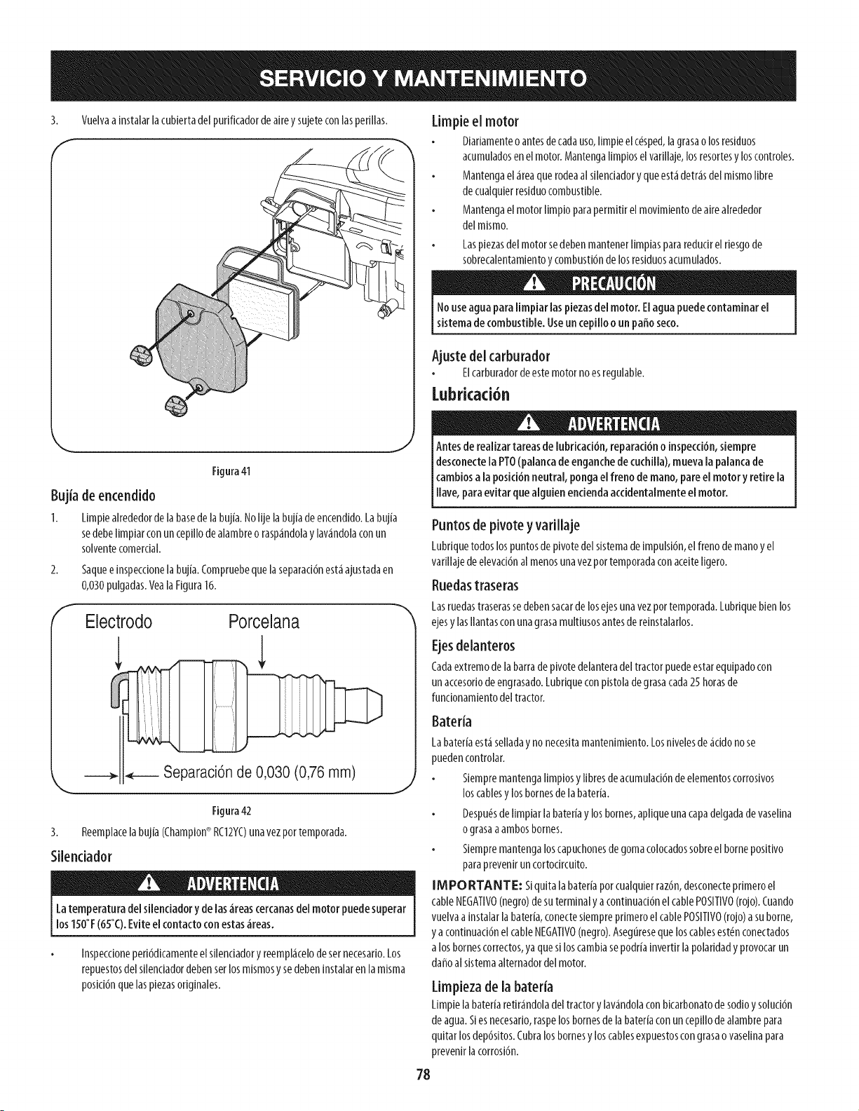
3. Vuelvaainstalarlacubiertadelpurificadordeaireysujeteconlasperillas.
Figura 41
Bujia de encendido
I. Limpiealrededorde labasedelabujia.Nolijelabujiadeencendldo.Labujia
sedebeIlmpiarconuncep[llodealambreorasp_ndolay lav_ndolaconun
solventecomerdal.
Saqueeinspecdonelabujia.Compruebequelaseparaci6nest,1ajustadaen
0,030pulgadas.Veala Figura16.
f
Electrodo Porcelana
2.
,J
Separaci6n de 0,030 (0,76 mm)
Figura42
3. Reemplacelabujia(Champion®RCI2YC)unavezpottemporada.
Silendador
Latemperaturadelsilenciadoryde las,ireascercanasdelmotorpuedesuperar
los150°F(65°C).Eviteel contactoconestas_ireas.
lnspecdoneperi6dicamenteelsilendadory reempl_icelodesetnecesario.Los
repuestosdelsilendadordebenserlosmismosy sedeben[nstahrenlamisma
posicl6nquelasplezasorlginales.
Limpieel motor
Diariamenteo antesdecadauso,limpieelc_sped,lagrasaolosresiduos
acumuladosenelmotor.Mantengalimploselvarillaje,losresortesyloscontroles.
Mantengael_ireaquerodeaalsilendadoryqueest,1detrasdelmismofibre
decualquierresiduocombustible.
Mantengaelmotorlimp[oparapermitirelmovimientodeairealrededor
delmismo.
LaspiezasdelmotorsedebenmantenerIlmpiaspararedudrelrlesgode
sobrecalentamlentoycombustl6ndelosreslduosacumulados.
11ouseaguaparalimpiar laspiezasdel motor.Elaguapuedecontaminarel
sistemade combustible.Useuncepillooun paffoseco.
Ajuste del carburador
Elcarburadordeestemotornoesregulable.
Lubricad6n
Antesderealizartareasde lubrkad6n, reparad6no inspecd6n,siempre
desconectela PTO(palancade enganchede cuchilla),muevala palancade
cambiosa laposici6nneutral,pongaelfreno de mano,pareel motory retirela
ave,paraevtar quea gu enericendaacedenta mentee motor.
Puntosde pivote y vafillaje
Lubriquetodoslospuntosdepivotedelsistemade[mpulsi6n,elfrenodemanoyel
varlllajedeelevacl6nalmenosunavezportemporadaconacelteIlgero.
Ruedastraseras
Lasruedastraserassedebensacarde losejesunavezportemporada.Lubriquebienlos
ejesy lasIlantasconunagrasamultlusosantesderelnstalarlos.
Ejesdelanteros
Cadaextremodelabarradepivotedelanteradeltractorpuedeestarequipadocon
unaccesoriodeengrasado.Lubriqueconpistoladegrasacada25horasde
funcionamientodeltractor.
Batefia
La baterfaest_selladay no necesitamantenimiento. Losnivelesde_cido no se
puedencontrolar.
Siempremantenga Iimplos y Ilbres deacumulacl6nde elementoscorrosivos
loscablesy los bornesde la bateffa.
Despu_sde limpiar la bateffay los bornes,apllque unacapa delgadade vasellna
o grasaa ambosbornes.
Siempremantenga los capuchonesde gomacolocadossobreel bornepositlvo
paraprevenk un cortodrcuito.
IMPORTANTE: Siquita labateria por cualquierraz6n,desconecteprimero el
cable NEGATIVO(negro)de suterminal y a continuaci6nel cable POSITIVO(rojo).Cuando
vuelvaa instalarla bateria,conectesiempre primero el cablePOSITIVO(rojo)a suborne,
y a continuaci6nel cableNEGATIVO(negro).Asegureseque los cablesest_nconectados
a los bornescorrectos,ya quesi los cambiasepodriainvertirlapolaridad y provocarun
daffo alsistemaalternadordel motor.
Limpiezade la bateria
Limpielabateriaretirandoladeltractorylavandolaconblcarbonatodesod[oy solud6n
deagua.Siesnecesario,raspelosbornesdelabateriaconuncepillodealambrepara
qultarlosdep6sitos.Cubralosbornesy loscablesexpuestoscongrasaovasellnapara
prevenklacorrosi6n.
78
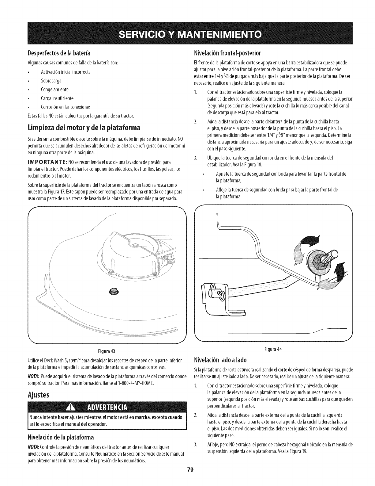
Desperfectosde la bateda
Algunascausascomunesdefallade[abateffason:
Actlvad6n[nlcial[ncorrecta
Sobrecarga
Congelamiento
Cargainsuficiente
Corrosi6nenlasconexiones
EstasfallasNOest_incubiertasporlagarantiadesutractor.
Limpiezadel motor y de la plataforma
Sisederramacombustibleoaceitesobrelam_quina,debelimpiarsede[nmediato.NO
permitaqueseacumulendesechosalrededordelasaletasderefrigerad6ndelmotorn[
ennlngunaotrapartedelam_qulna.
[MPORTANTE: NOserecomiendael usodeunalavadoradepresi6npara
limpiareltractor.Puededaffarloscomponentesel_ctdcos,loshusillos,laspoleas,los
rodamlentosoelmotor.
Sobrelasuperfldedelaplataformadeltractorseencuentrauntap6naroscacomo
muestralaFigura17.Estetap6npuedeserreemplazadoporunaentradadeaguapara
usarcomopartedeunsistemadelavadodela plataformadisponiblepot separado.
F
Figura43
UtiliceelDeckWashSystemTM paradesalojarlosrecortesdec#speddelaparteinferior
delaplataformae[mpedlrlaacumulad6ndesustandasqu[mlcascorrosivas.
NOTA:Puedeadquidrelsistemadelavadodelaplataformaatrav#sdelcomerdodonde
compr6sutractor.Param_s[nformad6n,flameal1-800-4-MY-HOME.
Ajustes
Nuncaintentehacerajustesmientrasel motorest_enmarcha,exceptocuando
asiIo espedficaelmanualdeloperador.
Nivelad6n de la plataforma
NOTA:Controlelapresl6ndeneum_tlcosdeltractorantesdereallzarcualquler
nlvelacl6ndela plataforma.ConsulteNeum_tlcosenlasecd6nServlc[odeestemanual
paraobtenerm_s[nformad6nsobrelapresi6ndelosneum_ticos.
Nivelad6n frontal-posterior
Elfrentede laplataformadecorteseapoyaenunabarraestabilizadoraquesepuede
ajustarparalaniveiaci6nfrontal-posteriordelaplataforma.Lapartefrontaldebe
estarentre1/4y_8depulgadam_sbajaquelaparteposteriordela plataforma.Deser
necesado,reallceunajustedelasigulentemanera:
I. Coneltractorestadonadosobreunasuperfidefirmeynivelada,coloquela
palancadeelevad6ndelaplataformaenlasegundamuescaantesdelasuperior
(segundaposici6nm_selevada)yrotelacuchlllaIom_scercaposibledelcanal
dedescargaqueest_paraleloal tractor.
2. Midaladlstancladesdelapartedelanterade lapuntadelacuchlllahasta
elplso,ydesdelaparteposteriordelapuntadelacuchlllahastaelpiso.La
pdmeramedici6ndebeserentreI/4" y3/8"menorquelasegunda.Determinela
distandaaproximadanecesadaparaunajusteadecuadoy,desernecesado,siga
conelpasosiguiente.
3. Ubiquelatuercadeseguddadconbddaenelfrentedelam_nsuladel
estabilizador.VealaFigura18.
Apdetelatuercadeseguddadconbddaparalevantarla partefrontalde
laplataforma;
Aflojelatuercadeseguddadconbddaparabajarla partefrontalde
laplataforma.
Figura44
Nivelad6n ladoa lado
S[la plataformadecorteestuvierarealizandoel cortedec_spedde forma despareja,puede
realizarseunajusteladoa lado. Desernecesado,realiceun ajustede la siguientemanera:
1. Conel tractor estadonadosobreuna superfide firme y nivelada,coloque
la palancadeelevad6n de la plataforma en la segundamuescaantesde la
superior (segundaposid6n m_selevada)y rote ambascuchillasparaque queden
perpendicularesal tractor.
2. Mida ladistancia desdelaparte externade la punta de lacuchilla[zquierda
hasta el piso,y desdela parte externade la punta de la cuchilladerechahasta
el piso. Lasdosmedicionesobtenidasdebenser [guales.S[no Io son,realiceel
siguiente paso.
3. Afloje, pero NOextraiga, el perno decabezahexagonalubicadoen la m_nsulade
suspensi6n[zquierdadela plataforma. Yeala Figura19.
79
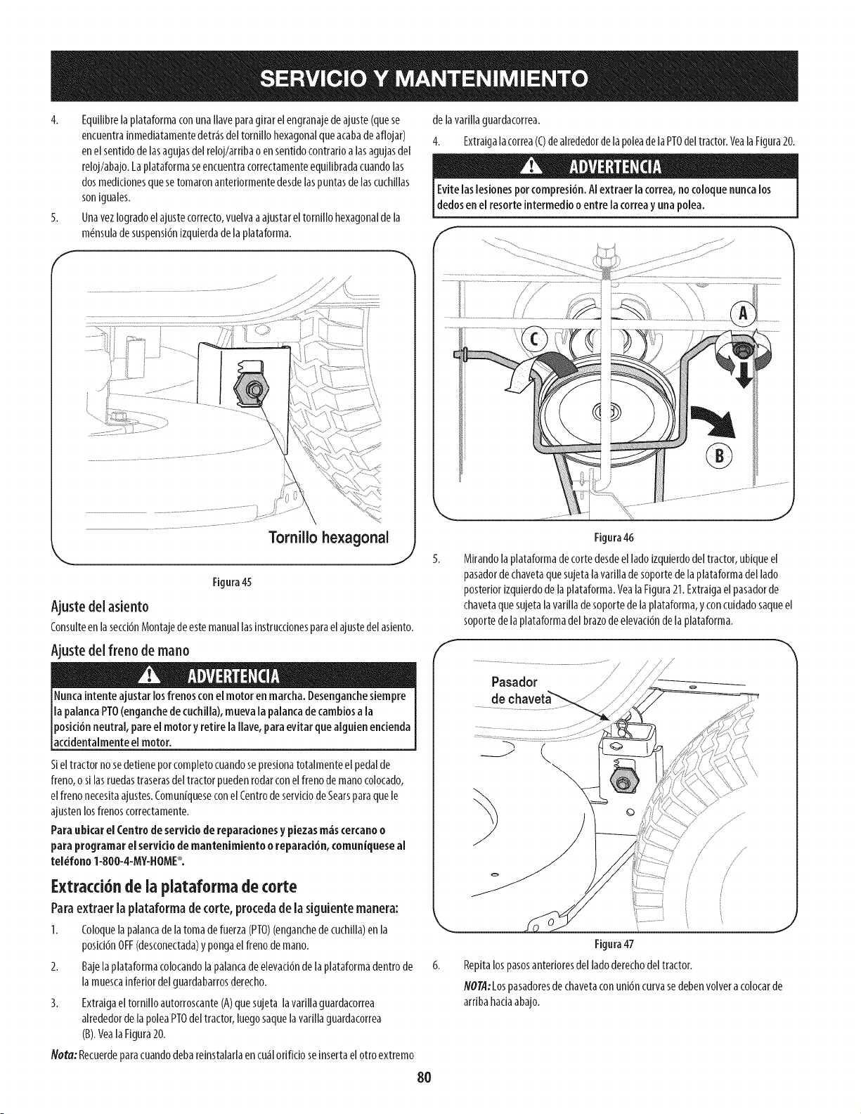
4. Equilibrelapiataformaconunallaveparagirarelengranajedeajuste(quese
encuentrainmediatamentedetr_sdeltomillohexagonalqueacabadeaflojar)
enelsentidodelasagujasdelreloj/arribao ensentidocontrarioalasagujasdel
reloj/abajo.Laplataformaseencuentracorrectamenteequilibradacuandolas
dosmedicionesquesetomaronanteriormentedesdelaspuntasdelascuchillas
soniguales.
5. Unavezlogradoelajustecorrecto,vuelvaaajustareltomillohexagonaldela
m_nsuladesuspensi6nizquierdadela plataforma.
f
Tomillo hexagonal
,.. j 5.
Figura45
Ajuste del asiento
Consulteenlasecci6nMontajedeestemanuallasinstrucdonesparaelajustedelasiento.
Ajuste del freno de mano /i
delavadllaguardacorrea.
4. Extraigalacorrea(C)dealrededordela poleadelaPTOdeltractor.Veala Figura20.
Evitelaslesionesporcompresi6mAIextraerlacorrea,nocoloquenuncalos
dedosenel resorteintermediooentrela correay unapolea.
Figura46
Mirandolapiataformadecortedesdeelladoizquierdodeltractor,ubiqueel
pasadordechavetaquesujetalavadlladesoportedelaplataformadellado
posteriorizquierdodelapiataforma.VealaFigura21.Extraigaelpasadorde
chavetaquesujetalavadlladesoportedelaplataforma,y concuidadosaqueel
soportedelaplataformadelbrazodeelevaci6ndelaplataforma.
Nuncaintenteajustarlosfrenosconel motorenmarcha.Desenganchesiempre
la palancaPTO(enganchede cuchilla),muevalapalancade cambiosala
posici6nneutral,pareelmotoryretire lallave,paraevitarquealguienendenda
acddentalmenteel motor.
Sieltractornosedetieneporcompletocuandosepresionatotalmenteel pedalde
freno,osilasruedastraserasdeltractorpuedenrodarconelfrenodemanocolocado,
elfrenonecesitaajustes.ComuniqueseconelCentrodeservic[odeSearsparaquele
ajustenlosfrenoscorrectamente.
Paraubicarel Centrode serviciode reparacionesy piezasm_scercanoo
paraprogramarel serviciode mantenimiento o reparaci6n,comuniqueseal
tel_fono 1-800-4-MY-HOME®.
Extracd6n de ia plataformade torte
Para extraer la plataforma de corte, proceda de la siguiente manera:
I. Coloquelapalancade latomadefuerza(PTO)(enganchedecucHlla)enla
posici6nOFF(desconectada)y pongaelfrenodemano.
2. Bajelaplataformacolocandolapalancadeelevad6ndelaplataformadentrode
lamuescainferiordelguardabarrosderecho.
3. Extraigaeltornilloautorroscante(A)quesujetalavadllaguardacorrea
alrededordelapoleaPTOdeltractor,luegosaquelavarillaguardacorrea
(B).VealaFigura20.
Nora:Recuerdeparacuandodebareinstalarlaencu_lorifidoseinsertaelotroextremo
\
Pasador
de
Figura47
Repitalospasosanterioresdeliadoderechodeltractor.
//
/
/
/ /
/
/
/
/
NOTA:Lospasadoresdechavetaconuni6ncurvasedebenvolveracolocarde
arribahaciaabajo.
80
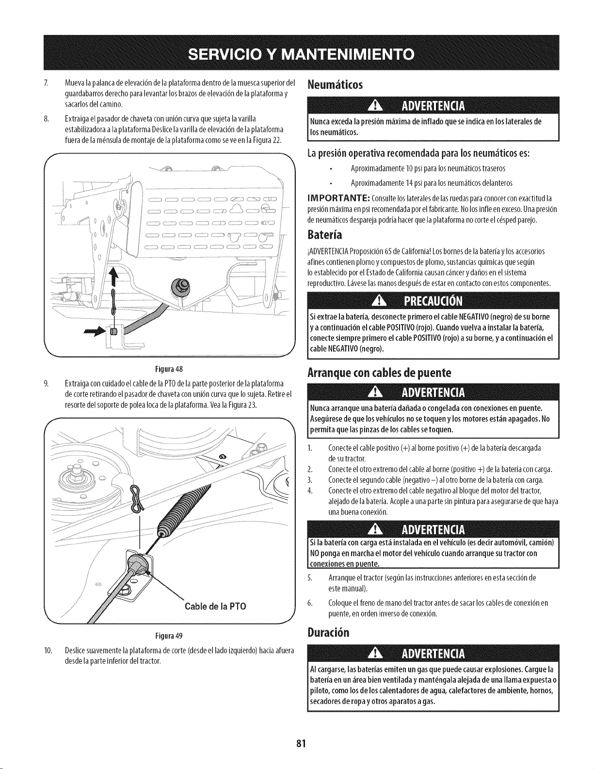
8.
Muevalapalancadeeievaci6ndela plataformadentrodelamuescasuperiordel
guardabarrosderechoparalevantarlosbrazosdeelevaci6ndelaplataformay
sacarlosdelcamino.
Extraigaelpasadordechavetaconuni6ncurvaquesujetalavafilla
estabilizadoraalaplataformaDeslicelavafilladeelevad6ndela plataforma
fueradelam_nsulademontajedelaplataformacomoseveenlaFigura22.
Figura48
ExtralgaconculdadoelcabledelaPTOdelaparteposteriordelaplataforma
decorteretlrandoelpasadordechavetaconuni6ncurvaquelosujeta.Retireel
resortedelsoportedepolealocadelaplataforma.VealaFigura23.
Neum ticos
Runcaexcedala presi6nm_ximade infladoqueseindicaenloslateralesde
losneum_tkos.
Lapresi6n operativa recomendadaparalos neum_ticoses:
Aproximadamente10psiparalosneumaticostraseros
Aproximadamente14psiparalosneumatkosdelanteros
[M PORTANTE: Consulteloslateralesdelasruedasparaconocerconexactitudla
presi6nmaximaenpsirecomendadaporelfabrkante.Nolosinfleenexceso.Unapresi6n
deneumatkosdesparejapodfiahacerquelaplataformanocorteelc_spedparejo.
BaterJa
]ADVERTENCIAProposJd6n65deCalifornia!Losbornesdelabatefiay losaccesofios
alinescontienenplomoy compuestosdeplomo,sustanciasquimkasquesegun
IoestableddoporelEstadodeCaliforniacausancancerydafiosenelsistema
reproductivo.Laveselasmanosdespu_sdeestarencontactoconestoscomponentes.
Siextraelabatefia,desconecteprimeroelcableNEGATIVO(negro)de suborne
y a continuaci6nel cablePOSITIVO(rojo).Cuandovuelvaainstalarlabateria,
conectesiempreprimeroelcablePOSmVO(rojo)a suborne,ya continuaci6nel
cabe NEGATVO(negro).
Arranqueconcablesde puente
Nuncaarranqueunabatefiadafiadaocongeladaconconexionesen puente.
Aseguresedequelosvehkulosnosetoqueny losmotoresest_napagados.No
permitaquelaspinzasde loscablessetoquen.
10.
Cable de la PTO
Figura49
Deslicesuavementelaplataformadecorte(desdeelladoizquierdo)hadaafuera
desdelaparteinferiordeltractor.
1. Conecteel cable positivo (+) al borne posJtivo(+) de la batefia descargada
de sutractor.
2. Conecteel otro extremo delcableal borne (positivo +) de labatefia concarga.
3. Conecteel segundocable (negativo-) al otro borne de la bater[aconcarga.
4. Conecteel otro extremo delcable negativoal bloque del motor del tractor,
alejadode la batefia. Acoplea unaparte sin pintura paraasegurarsede que haya
una buenaconexi6n.
cone×iones en luente.
5. Arranqueeltractor(segunlasinstrucdonesantefioresenestasecd6nde
estemanual).
6. Coloqueelfrenodemanodeltractorantesdesacarloscablesdeconexi6nen
puente,enordeninversodeconexi6n.
l)uraci n
AIcargarse,lasbatefiasemitenungasquepuedecausarexplosiones.Carguela
batefiaenun _reabienventiladaymant_ngalaalejadade unallamaexpuestao
Ipiloto, comolosdeloscalentadoresde agua,calefactoresde ambiente,hornos,
secadoresde ropay otrosaparatosagas.
81
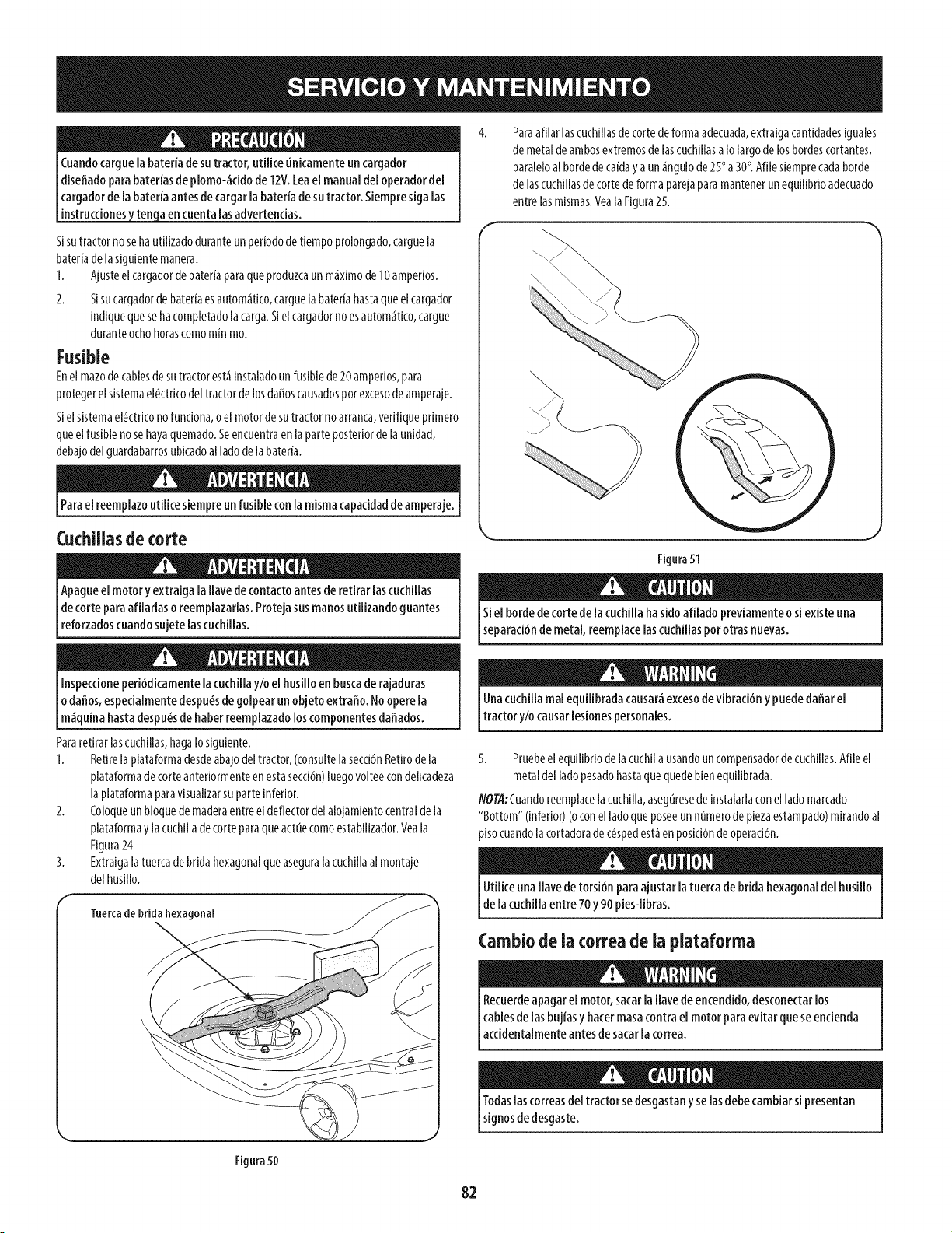
Id'_nual de[operadordel
I_tor. Siempresigalas
instruccionesten a encuentalasadvertencias.
Sisutractornosehautilizadoduranteunperiododetiempoprolongado,carguela
bater[adelasiguientemanera:
1. Ajusteelcargadordebater[aparaqueproduzcaunm_ximode10amperios.
2. Sisucargadordebateriaesautom_tko,carguelabater[ahastaqueelcargador
[ndiquequesehacompletadolacarga.Sielcargadornoesautom_tico,cargue
duranteochohorascomom[nimo.
Fusible
Enel mazodecablesdesutractorestainstaladounfusiblede20amperios,para
protegerelsistemael_ctricodeltractordelosdaffoscausadosporexcesodeamperaje.
Sielsistemael_ctriconofundona,o elmotordesutractornoarranca,verifiqueprimero
queel fusiblenosehayaquemado.Seencuentraenlaparteposteriordelaunidad,
debajodelguardabarrosubicadoalladodelabateffa.
Parael reemplazoutilicesiempreunfusibleconlamismacapacidaddeamperaje.
Cuchiiiasde corte
Apagueelmotoryextraigala Ilavede contactoantesderetirar lascuchillas
decorteparaafiiariaso reempiazarias.Protejasusmanosutiiizandoguantes
[reforzadoscuandosujete ascuch as.
Inspecdoneperi6dicamentelacuchillay/oel husilloen buscaderajaduras
odaffos,espedalmentedespu_sde golpearunobjetoextraffo.Nooperela
[m_quna hastadespu_sde haberreempazadooscomponentesdaffados.
Pararetirar[ascuchH[as,haga[osiguiente.
1. Retirelaplataformadesdeabajodeltractor,(consultelasecci6nRetirodela
plataformadecorteanteriormenteenestasecd6n)luegovolteecondelicadeza
laplataformaparavisualizarsuparteinferior.
2. Coloqueunbloquedemaderaentreeldeflectordelalojamientocentraldela
plataformay la cucHlladecorteparaqueactuecomoestabHizador.Yeala
Figura24.
3. ExtraigalatuercadebridahexagonalqueaseguralacuchHlaal montaje
delhusi[Io.
Tuerca de brida hexagonal
\
Figura50
Paraafilar lascuchillasde corte deforma adecuada,extraiga cantidadesiguales
de metal de ambosextremosde las cuchillasa Io largode los bordescortantes,
paraleloal bordede caiday a un _ngulo de 25° a 30°. Afile siemprecadaborde
de las cuchiliasde corte de forma parejapara mantenerun equilibrio adecuado
entre lasmismas.YealaFigura25.
Figura51
Siel bordedecortede ia cuchillahasidoafiladopreviamenteosi existeuna
separaci6nde metal,reemplacelascuchillaspot otrasnuevas.
Onacuchillamal equilibradacausar_excesodevibraci6ny puededaffarel
tractory/o causarlesionespersonales.
5. Pruebeel equilibrio de la cuchillausandoun compensadordecuchillas.Afile el
metal del ladopesadohastaquequedebien equilibrada.
NOTA:Cuandoreemplacelacuchilla,aseguresede [nstalarlaconel lado marcado
"Bottom" (inferior) (oconel lado que poseeun numero de plezaestampado)mirandoal
plso cuandola cortadorade c_spedest_ en posid6nde operad6n.
Utiliceunaflarede torsi6nparaajustarlatuercadebridahexagonaldel husillo
de lacuchillaentre70y90pies-libras.
Cambiode la correade la plataforma
Recuerdeapagarel motor,sacarlaflarede encendido,desconectarlos
cablesdelasbujiasy hacermasacontrael motorparaevitarqueseencienda
accdenta menteantesde sacaracorrea.
Todaslascorreasdeltractor sedesgastanyselasdebecambiarsi presentan
signosdedesgaste.
82
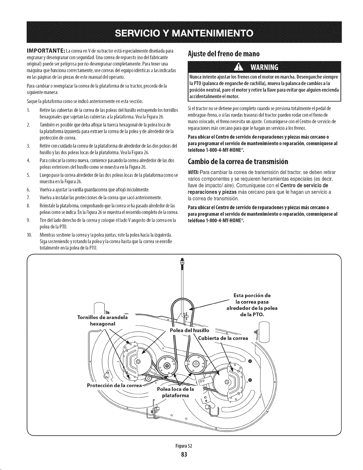
[MPORTANTE: LacorreaenVdesutractorest&espedaimentediseffadapara
engranary desengranarconseguridad.Unacorreaderepuesto(nodelfabricante
original)puedesetpeligrosapotnodesengranarcompletamente.Paratenetuna
m_quinaquefuncionacorrectamente,usecorreasdelequipoid_nticasalasindicadas
enlasp_ginasdelaspiezasdeestemanualdeloperario.
Paracambiaroreemplazarlacorreadelaplataformadesutractor,procedadela
siguientemanera:
Saquelaplataformacomoseindic6anteriormenteenestasecci6n.
1. Retirelascubiertasdelacorreadelaspoleasdelhusilloextrayendolostornillos
hexagonalesquesujetanlascubiertasalaplataforma.VealaFigura26.
2. Tambi_nesposiblequedebaaflojarlatuercahexagonaldelapoleaIocade
laplataformaizquierdaparaextraerlacorreadelapoleay dealrededorde la
protecci6ndecorrea.
3. Retireconculdadolacorreadelaplataformadealrededordelasdospoleasdel
husilloy lasdospoleasIocasdelaplataforma.YealaFigura26.
4. Paracolocarlacorreanueva,comlencepasandolacorreaalrededordelasdos
poleasexterioresdelhusillocomosemuestraenlaFigura26.
5. Luegopaselacorreaalrededorde lasdospoleasIocasdelaplataformacomose
muestraenlaFigura26.
6. Vuelvaaajustarlavarillaguardacorreaqueafloj6inicialmente.
7. Vuelvaainstalarlasproteccionesdelacorreaquesac6anteriormente.
8. Reinstalelaplataforma,comprobandoquelacorreasehapasadoalrededordelas
poleascomoseindica.EnlaFigura26semuestraelrecorridocompletodelacorrea.
9. Tiredelladoderechodelacorreay coloqueelladoVangostodelacorreaenla
poleadelaPTO.
10. Mientrassostienelacorreay lapoleajuntas,rotelapoleahacialaizquierda.
Sigasosteniendoy rotandolapoleay lacorreahastaquelacorreaseenrolle
totalmenteenlapoleadelaPTO.
F
Ajustedelfreno de mano
Nuncaintenteajustarlosfrenosconel motoren marcha.Desenganchesiempre
[a PTO(palancadeenganchedecuchiila),mueva[apalancade cambiosa[a
posici6nneutral,paree[ motory retire[a[[aveparaevitarquea[guienencienda
accidentalmenteel motor.
Sieltractornosedetieneporcompietocuandosepresionatotalmenteelpedalde
embrague-freno,o silasruedastraserasdeltractorpuedenrodarconel frenode
manocolocado,elfrenonecesitaunajuste.Comun[queseconel Centrodeserviciode
reparacionesmascercanoparaquelehaganunservicioalosfrenos.
ParaubicarelCentrodeserviciodereparadonesy piezasre,iscercanoo
paraprogramar el servido de mantenimiento o reparaci6n,comuniqueseal
teidfono 1-SOO-4-MY-HOME®.
Cambiode iacorrea de transmisi6n
NOT,q:Para cambiar la correa de transmisi6n del tractor, se deben retirar
varios componentes y se requieren herramientas especiales (es decir,
Ilavede impacto/aire). Comuniquese con el Centro de servicio de
reparaciones y piezas mas cercano para que le hagan un servicio a
lacorrea de transmisi6n.
ParaubicarelCentrode servido dereparacionesy piezasre,iscercanoo
paraprogramar el servido demantenimiento o reparaci6n,comuniqueseal
tel_fono 1-800-4-MY-HOME®o
Cubierta de [a correa
Protecci6n de la ¢orrea
Figura52
83
Nuncaalmacenetractor de c_spedcon combustibleenel tanque en un
espaciocerradooen _reasconpocaventilaci6n,dondelosgasesdel
combustiblepuedanalcanzarelfuego, chispaso una luzpiloto comola que
tienen algunoshomos,calentadoresde agua,secadoresde ropa oalgun
otro dispositivoagas.
Preparad6ndeimotor
[M PORTANTE: Elcombustiblequequedaen el tanquecuandohatecaiorse
deterioray ocasionagravesprobiemasdeencendido.
Paraevitarqueseformendep6sitosdegomadentrodel carburadordel motor
y posiblesdesperfectosene[ motor,el sistemadecombustibledebeservadado
compietamente,o sedebetratarlagasolinaconunestabiiizadorparaevitare[
deterioro.
1. Siutilizaunestabilizadordecombustible:
a. Lealasinstrucdonesy recomendadonesdelfabrkantedel producto.
b. Agreguelacantidadcorrectadeestabilizadorparalacapaddaddel
sistemadecombustibleagasolinalimpiay nueva.
c. Lleneeldep6sitodecombustibleconcombustibletratadoy haga
fundonarelmotor2-3minutosparaestabilizarel combustibledentro
delcarburador.
Cuandovadeelsistemade combustible:
a. Nodreneelcombustiblecuandoelmotorest_caliente.Permitaque
elmotorseenfriebien.Dreneelcombustibledentrodeun redpiente
aprobadoy alairelibre,lejosdecualquierllamaexpuesta.
b. Dreneungranvolumendecombustibledesdeeldep6sito,desco-
nectandolaI[neade combustibledelfiltro decombustibleenI[neaque
seencuentracercadel motor.
Lagaso[inaessumamenteinf[amab[ey puedeserexp[osivaendertas
condkiones.Vade[a antesdea[macenare[equipodurantepeffodos
proiongados.Drenee[ combustibleunicamentedentro de un recipiente
aprobadoy al aire[ibre, [ejosde cuaiquierllamaexpuesta.Dejeque
el motor seenfffe.Antesde drenar el combustible,apaguecigarriiios,
cigarros,pipasyotras fuentesde combusti6n.Vadelagasolinaen un _rea
bienventilada,le]osdecualquierfuente de llamaochispas,[nduidocualquier
artefactoconluzpiloto.AImacenelagasolinaen un redpienteaprobado,enun
lugarseguro.
Extraigalabujiay viertauna(1)onzadeaceiteparamotorporelorifido
delabujiaeneldlindro.Hagagirarel motorvariasvecesparadistribuirel
aceite.Vuelvaacolocarlabujia.
Eldrenajede loscombustibles
1. Localkeelfiltro decombustible,queseencuentraenel ladoizquierdodel
motor,y puedeserconectadoalmotorconunacorreade empate.
2. Cortarlacorreade lacorbata,si est_presente,entoncesemergenteenla
abrazaderaenI[neaenelfiltro decombustibleconunpardealkates,deslke
laabrazaderadela I[neadecombustible.
Quitelaiineadecombustibleen lalineaylafugade combustibleenun
redpienteaprobado.
Preparad6nde ia tractor de c sped
1. Limpiey lubriquelatractorcomosedescribeenlas[nstrucdonesde
lubrkad6n.
2. Noutiliceunalavadoraapresi6nn[unamangueradejardinparalimpiarsu
unidad.
3. Almacenelatractoren unazonalimpiayseca.Nolaalmacenecercade
materialescorrosivoscomoporejemplofertllizantes.
c. Vuelvaacontectarlalineadecombustibley hagafundonarel motor
hastaquecomiencea fallar,useentoncesel cebadorparamantenerel
motoren marchahastaagotartodoelcombustibledelcarburador.
d. VuelvaadesconectarlaI[neadecombustibley drenelagasolina
restanteenelsistema.
Lagasolinaesunasustanciat6xica.Eliminelagasolinaadecuadamente.
Comunklueseconlasautoridadeslocalespara averiguarcuries sonlos
_todosadecuadospara eliminar la gasolina.
84
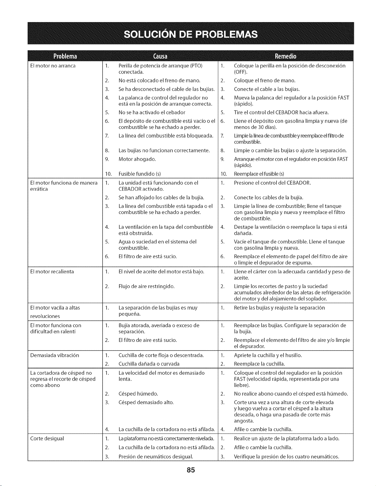
El motor no arranca
El motor funciona de manera
err_tica
El motor recalienta
1. Perilla de potencia de arranque (PTO)
conectada.
2. No est_ colocado el freno de mano.
3. Se ha desconectado el cable de las bujias.
4. La palanca de control del regulador no
est_ en la posici6n de arranque correcta.
5. No se ha activado el cebador
6. El dep6sito de combustible est_ vacio o el
combustible se ha echado a perder.
7. La linea del combustible est_ bloqueada.
8. Las bujias no funcionan correctamente.
9. Motor ahogado.
10. Fusible fundido(s)
1. La unidad est_ funcionando con el
CEBADOR activado.
2. Se han aflojado los cables de la bujia.
3. La linea del combustible est_ tapada o el
combustible se ha echado a perder.
4.
5.
6.
La cortadora de c6sped no
regresa el recorte de c6sped
como abono
La ventilaci6n en la tapa del combustible
est_ obstruida.
Agua o suciedad en el sistema del
combustible.
El filtro de aire est_ sucio.
1. El nivel de aceite del motor est_ bajo.
2. Flujo de aire restringido.
1. Coloque la perilla en la posici6n de desconexi6n
(OFF).
2. Coloque el freno de mano.
3. Conecte el cable alas bujias.
4. Mueva la palanca del regulador a la posici6n FAST
(r_pido).
5. Tire el control del CEBADOR hacia afuera.
6. Llene el dep6sito con gasolina limpia y nueva (de
menos de 30 dias).
7. Limpie la linea de combustible y reemplace el filtro de
combustible.
8. Limpie o cambie las bujias o ajuste la separaci6n.
9. Arranque el motor con el regulador en posici6n FAST
(r_pido).
10. Reemplace el fusible (s)
1. Presione el control del CEBADOR.
2.
3.
El motor vacila a altas 1. La separaci6n de las bujias es muy 1.
revoluciones pequeha.
El motor funciona con 1. Bujia atorada, averiada o exceso de 1.
dificultad en ralenti separaci6n.
2. El filtro de aire est_ sucio. 2.
Demasiada vibraci6n 1. Cuchilla de corte floja o descentrada. 1.
2. Cuchilla dahada o curvada 2.
1. La velocidad del motor es demasiado 1.
lenta.
Corte desigual
2. C6sped humedo.
3. C6sped demasiado alto.
Conecte los cables de la bujia.
Limpie la Ifnea de combustible; Ilene el tanque
con gasolina limpia y nueva y reemplace el filtro
de combustible.
4. La cuchilla de la cortadora no est_ afilada.
1. La plataforma no est_ correctamente nivelada.
2. La cuchilla de la cortadora no est_ afilada.
3. Presi6n de neum_ticos desigual.
Destape la ventilaci6n o reemplace la tapa si est_
dahada.
5. Vacie el tanque de combustible. Llene el tanque
con gasolina limpia y nueva.
6. Reemplace el elemento de papel del filtro de aire
o limpie el depurador de espuma.
1. Llene el c_rter con la adecuada cantidad y peso de
aceite.
2.
3.
Limpie los recortes de pasto y la suciedad
acumulados alrededor de las aletas de refrigeraci6n
del motor y del alojamiento del soplador.
Retire las bujias y reajuste la separaci6n
4.
1.
2.
3.
Reemplace las bujias. Configure la separaci6n de
la bujia.
Reemplace el elemento del filtro de aire y/o limpie
el depurador.
Apriete la cuchilla y el husillo.
Reemplace la cuchilla.
Coloque el control del regulador en la posici6n
FAST (velocidad r_pida, representada pot una
liebre).
No realice abono cuando el c6sped est_ humedo.
Corte una vez a una altura de corte elevada
y luego vuelva a cortar el c6sped a la altura
deseada, o haga una pasada de corte m_s
angosta.
Afile o cambie la cuchilla.
Realice un ajuste de la plataforma lado a lado.
Afile o cambie la cuchilla.
Verifique la presi6n de los cuatro neum_ticos.
85

Esta pagina se dej6 intencionalmente en blanco. Utilice esta pagina para tomar notas acerca de su tractor.
86
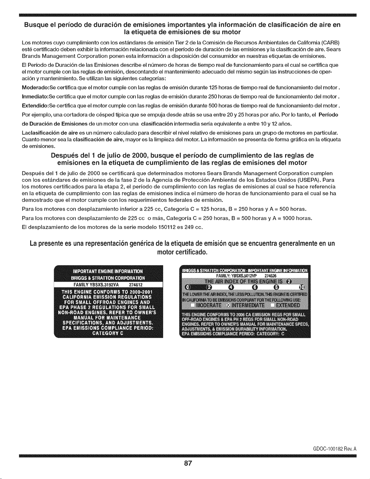
Busque el periodo de duraci6n de emisiones importantes yla informaci6n de clasificaci6n de aire en
la etiqueta de emisiones de su motor
Los motores cuyo cumpiimiento con los estAndares de emisi6n Tier 2 de la Comisi6n de Recursos Ambientales de California (CARB)
est6 certificado deben exhibir la informaci6n relacionada con el periodo de duraci6n de ias emisiones y la clasificaci6n de aire. Sears
Brands Management Corporation ponen esta informaci6n a disposici6n del consumidor en nuestras etiquetas de emisiones.
Ei Periodo de Duraci6n de las Emisiones describe el nQmero de horas de tiempo real de funcionamiento para el cuai se certifica que
el motor cumpie con ias reglas de emisi6n, descontando el mantenimiento adecuado del mismo segQn las instrucciones de oper-
aci6n y mantenimiento. Se utilizan las siguientes categonas:
Moderado:Se certifica que el motor cumpie con las reglas de emisi6n durante 125 horas de tiempo real de funcionamiento del motor.
Inmediato:Se certifica que el motor cumpie con las reglas de emisi6n durante 250 horas de tiempo real de funcionamiento del motor.
Extendido:Se certifica que el motor cumpie con las reglas de emisi6n durante 500 horas de tiempo real de funcionamiento del motor.
Por ejemplo, una cortadora de c6sped tJpica que se empuja desde arras se usa entre 20 y 25 horas por aSo. Por Io tanto, el Periodo
de Duraci6n de Emisiones de un motor con una clasificaci6n intermedia sena equivaiente a entre 10 y 12 aSos.
Laciasificaci6n de aire es un nQmero calculado para describir el nivel relativo de emisiones para un grupo de motores en particular.
Cuanto menor sea la clasificaci6n de aire, mayor es la limpieza del motor. La informaci6n se presenta de forma grAfica en la etiqueta
de emisiones.
Despu_s del 1 de julio de 2000, busque el periodo de cumplimiento de las reglas de
emisiones en la etiqueta de cumplimiento de las reglas de emisiones del motor
Despu6s del 1 de julio de 2000 se certificarA que determinados motores Sears Brands Management Corporation cumplen
con los estAndares de emisiones de la fase 2 de la Agencia de Protecci6n Ambientai de los Estados Unidos (USEPA). Para
los motores certificados para la etapa 2, el periodo de cumplimiento con ias reglas de emisiones al cual se hace referencia
en la etiqueta de cumplimiento con las reglas de emisiones indica el nQmero de horas de funcionamiento para el cual se ha
demostrado que el motor cumple con los requerimientos federales de emisi6n.
Para los motores con desplazamiento inferior a 225 cc, Categoria C = 125 horas, B = 250 horas y A = 500 horas.
Para los motores con desplazamiento de 225 cc o mAs, Categoria C = 250 horas, B = 500 horas y A = 1000 horas.
El desplazamiento de los motores de la serie modelo 150112 es 249 cc.
La presente es una representaci6n gen_rica de la etiqueta de emisi6n que se encuentra generaimente en un
motor certificado.
FAMILYYBSXS.3192VA 274812
GDOC-100182Rev.A
87
(Esta p_.ginase aplica s61oen EE.UU. y Canada.).
Sears Brands Management Corporation, el Consejo de Recursos Ambientales de California (CARB)
y la Agencia de Protecci6n Ambiental de los Estados Unidos (EPA)
Declaraci6n de garantia del sistema de control de emisiones (derechos y obligaciones de la garanfia de defectos del propi=
etario)
LA COBERTURADE LA GARANTJADECONTROLDEEMISIONESES Y PARALOSMODELOSCERTIFICADOSDELANO 1997YPOSTERIORES,
APLIOABLEA LOS MOTORESCERTIFICADOSCOMPRADOSEN CALIFOR- QUESE COMPRENY UTILICENENCUALQUIERPARTEDE LOSESTADOS
NIA EN1995Y POSTERIORMENTE,QUESE UTILIZANENCALIFORNIA, UNIDOS(Y A PARTIRDEL 1 DE ENERODE2001 ENCANADA).
Declaraci6n de garanfia sobre defectos en el control de emisiones para California y los Estados Unidos
ElConsejode RecursosAmbientalesde California(CARB),la EPA(Agencia
de Protecci6nAmbientalde los EE.UU.)y Searstienenel gusto de explicarla
garantiadel sistemade control de emisionespara motoresdela_o 2000y para
elfuturo con relaci6na motorespeque_ostodo terreno(SORE).En California,
los nuevosmotorespeque_ostodo terrenodebenestar dise_ados,construidos
y equipadosparacumplircon las rigurosasnormasanti-smogdelestado.En
el restode los EstadosUnidos,losmotoresnuevostodoterrenode encendido
porchispacertificadosparael a_o 1997debencumplirest_ndaressimilares
establecidospot la EPA.Searsdebegarantizarel sistemade control de emis-
ionesde su motorparalosperiodosde tiempo enumeradosa continuaci6n,
siemprequeno hayaabuso,negligenciao mantenimientoindebidode su
motortodoterrenopeque_o.Su sistemade controlde emisionespuedeincluir
piezastalescomoel carburador,el filtro de aire, el sistemade encendido,el
silenciadoryel conversorcatalitico.Tambienpuedeincluirconectoresy otras
unidadesrelacionadascon las emisiones.Dondeexistaunacondici6ncubierta
por la garantia,Searsreparar_su peque6omotortodo terrenosin costo alguno
incluyendodiagn6stico,piezasy manode obra
Cobertura de la garantJa Sears para defectos en el control de emJsiones
Los motorestodo terrenopeque6osest_ngarantizadosen Io relativoalcontrol alas disposicionesque se indiquena continuaci6n.Si una parte de su motor
de emisionesparadefectosenpiezasduranteun periodode dos a_os,sujeto cubiertapot la garanfiaes defectuosa,Sears reparar_o sustituir_dichaparte.
Responsabilidades del propietario en relacibn con la garantia
Comopropietariodel motortodo terrenopeque_o,Ud.es responsablede la
realizaci6ndel mantenimientorequeridoquese incluyeen las instrucciones
de operaci6ny mantenimiento.Searsrecomiendaquese conserventodoslos
recibosrelativosal mantenimientode su motortodoterrenopeque_o,pero
no pude denegarla garantiasimplementepor la faltade los mismos,o por su
incumplimientodel mantenimientoprogramatic.Comopropietariodel motor
peque_otodoterrenodebe saberque, sin embargo,Sears lepuedenegar
lacoberturade lagarantiasi su motortodoterrenopeque6oouna piezadel
mismohanfalladodebido a abuso,negligencia,mantenimientoindebidoo
a modificacionesno aprobadas.Ud.es responsablede presentarsu motor
todoterrenopeque6oa un distribuidorde serviciosSearsautorizadotan pronto
comoaparezcaun problema.Las reparacionesde la garantiasinconfiicto
debencompletarseen un plazode tiempo razonable,no superiora 30 dias.Si
tienealgunapreguntarespectoa sus derechosy responsabilidadesreferen-
tes a la garantia,debe contactarcon un representantede serviciosSearsal
1--800--469--4663.Lagarantiade emisioneses unagarantiapor defectos.Los
defectosse juzgande acuerdocon elfuncionamientonormalde unmotor.La
garantiano est_relacionadacon unapruebade emisionesen uso.
Disposiciones de la garantJa Sears para defectos en el control de emJsiones
Las siguientesson disposicionesespecificasrelacionadascon la coberturade lagarantia paradefectosen el controlde emisiones.Esun a_adidoa la garantiade
motorSearsparamotoresno reguladosque seencuentraen lasinstruccionesde funcionamientoy mantenimiento.
1. Piezascon garantia
La coberturade esta garantiase extiendeL]nicamentealas piezas
queaparecena continuaci6n(las partesde lossistemasde control de
emisiones),siempreque dichaspiezasestuvieranya en el motoren el
momentode su compra.
a. Sistemademedici6n de combustible
• Sistema de enriquecimientopara arranqueen frio
• Carburadory partesinternas
• Bombade combustible
b. Sistemadeinducci6nde aire
• Filtrode aire
• Colector de admisi6n
c. Sistemadeencendido
• Bujia(s)de encendido
• Sistema de encendidomagneto
d. Sistemadelcatalizador
• Convertidorcatalitico
• Colector de escape
• Sistema de inyecci6nde aireo v_lvulade impulsos
e. Elementosvariadosusadosenlos sistemasanteriores
• Wlvulas de vacio,sensiblesa temperatura,posici6ny tiempo
e interruptores
• Conectoresy montajes
2. AIcancede la cobertura
Searsgarantizaal poseedorinicialy a loscompradoressubsiguientes
quelas piezascon garantiano tendr_n defectosen materialesni mano
de obra que provoquenla falla de las mismasduranteun periodode
dos aSosa partirde la fechaen queel motorse entregaa un comprador
particular.
3. Sin cargo
La reparaci6no reemplazodecualquierpartecon garantia se realizar_
sin cargo alguno parael poseedor,incluyendotareasde diagn6sticoque
permitandeterminarsi una partecon garantiaes defectuosa,siempreque
dichodiagn6sticose realiceen un distribuidorde serviciosSearsautoriza-
do. Parael serviciode lagarantia de emisiones,contacteal distribuidorde
serviciosSearsautorizadom_s cercanoincluidoen las"P_ginasamarillas"
en lascategorias"Motores,gasolina","Motoresde gasolina","Podadoras
de cesped",o similares.
4. Reclamacionesy exclusionesa la cobertura
Las reclamacionesde lagarantia debenenviarsede acuerdocon las
disposicionesde la politica de garantia para motoresSears.La cobertura
de lagarantia excluir_defectosen piezascongarantia queno scan partes
originalesSears,o abuso,negligenciao mantenimientoincorrecto,tal y
como se estableceen la politica de garantia para motoresSears.Searsno
es responsablede lasfallas en piezascon garantia provocadaspor el uso
de partesa6adidas,que no scan originaleso quese hayan modificado.
5. Mantenimiento
Cualquierpartecon garantiaque no esteprogramadapara serreem-
plazadacomomantenimientorequerido,o que s61odebainspeccionarse
regularmentealefecto de "inspeccioneo reemplacesegL]nsea necesario",
estar_garantizadacontradefectosduranteel periodode la garantia.Todas
las piezasgarantizadasqueesten programadaspara su reemplazopara
cumplir con los requisitosde mantenimientoestar_ngarantizadass61o
por el periodoanterior al primerreemplazoprogramaticparadicha pieza.
Cualquierpiezade recambioquesea equivalenteen funcionamientoy
durabilidadpuedeusarse para realizar mantenimientoo reparaciones.El
propietarioes responsablede realizartodoel mantenimientorequerido,tal
y comose define en las instruccionesde funcionamientoy mantenimiento
Sears
6. Coberturaindirecta
Porla presente,la coberturase extiendea la falla de cualquiercomponente
de motorprovocadapot la falla de unapieza con garantiaque este todavia
en periodode garantia.
En los EstadosUnidosy Canad_hay unalinea de atenci6nde 24 horas,1-800-469--4GG3,quecuentacon unmenL]conmensajespre-grabadosque contienen
informaci6npara el mantenimientode motores.
DECLARACIONFEDERALy/oDECALIFORNIASOBRE GARANTJAS EN EL CONTROL DE EIVIISIONES
SUS DERECHOS Y OBLIGACIONES EN CUANTO A LA GARANTJA
MTDConsumerGroupInc, laAgencia de Protecci6nMedioambientalde los EstadosUnidos(EPA),y paraaquellosproductoscertificadosparasu ventaen el es-
tadode California,el Departamentode los Recursosdel Aire de California(CARB)secomplacenen explicarla garanfiaque cubre al sistemade control (ECS)de
emisiones(evaporativasy/o de escape)de su equipoy motor(motor de equipos de exteriores)de encendidopot chispaparatodo terreno,peque_o,deexteriores
del a_o2006 y a_osposterioresEn California,losnuevosmotoresde equipos de exterioresdebenestar dise_ados,construidosy equipadospara cumplircon las
estrictasnormasantipoluci6ndel Estado(en otrosestados,losequiposdel a_o 1997y modelosposterioresdebenserestar dise_ados,construidosy equipados
para cumplircon las regulacionesde motoresde encendidopor chispa para todoterrenopeque_osde laAgencia de Protecci6nMedioambientalde los Estados
Unidos,(EPA).MTDConsumerGroupInc. debe garantizarel sistemade controlde emisiones(ECS) de su motorde equipos de exteriorespot el periodode
tiempo indicadom_sabajo,siemprey cuando no existauso incorrecto,negligenciao mantenimientoinadecuadode dicho motor.
Su ECSpuedeincluir piezastales como el carburador,el sistemade inyecci6nde combustible,el sistemade encendido,el convertidorcatalitico,losdep6sitos
de combustible,laslineas de combustible,lostaponesde combustible,las v_lvulas,contenedores,filtros, manguerasde vapor,abrazaderas,conectoresy otros
componentesafinesrelacionadoscon lasemisiones.
Dondeexista unacondici6ncubiertapor la garantia,MTDConsumerGroupInc. reparar_su motorde equiposde exterioressincosto alguno incluyendoel
diagn6stico,las piezasy la mano de obra.
COBERTURA DE LA GARANTJA DEL FABRICANTE:
Este sistemade control de emisionesse garantizaporel t@minode dosaSos.Si algunapieza relacionadacon lasemisionesde su motorde equiposde
exterioreses defectuosa,MTDCONSUMERGROUPINC. reparar_o sustituir_dichapieza.
RESPONSABILIDADES DEL PROPIETARIO SEGUN LA GARANTJA:
En su car_cterde propietariodel motorde equipos de exteriores,usted es responsabledel mantenimientorequeridoquese especificaen el manualdel propieta-
rio.MTDConsumerGroupInc le recomiendaque conservetodos losrecibos quecubrenel mantenimientode su motor,no obstanteIo cual MTDConsumerGroup
Inc no podr_denegarel cumplimientode lagarantia Qnicamentepor lafaltade los recibos.
Comopropietariodel motorde equiposde exteriores,usteddebe saber queMTDConsumerGroupInc. puededenegarlacoberturade lagarantia si su motoro
unapiezadel mismofallandebido a uso incorrecto,negligencia,mantenimientoindebido o a modificacionesno aprobadas.
Ustedes responsablede presentarsu motoral centrode distribuci6no serviciotecnico de MTDConsumerGroupInc. tan prontocomo aparezcael problema.Las
reparacionescubiertaspor la garantiase debenIlevara caboen unlapso razonableque no excedade30 dias. Si tiene alguna preguntarespectode lacobertura
de la garantia, p6ngaseen contactocon el Departamentodel ServicioT@nicode MTDConsumerGroupInc. al telefono1-800-800-7310o pot correoelectr6nico
en http://support.mtdproducts.com
COBERTURA DE LA GARANTJA DE EMISIONES GENERALES:
MTDConsumerGroupIncgarantizaal compradorfinal y a cadacompradorsubsiguienteque el motorde equiposde exteriores:est_ dise_ado,construidoy
equipadode modo de cumplir contodas las regulacionesaplicablesy quese encuentralibre de defectosde materialesy de fabricaci6nque pudierencausarla
falla de una piezagarantizadaidentica,en todos los aspectos materialesa la piezadescriptaen la solicitudde certificaci6nde MTDConsumerGroupInc.
El periodode garantiacomienzaen la fechade entregadel motoral compradorfinal o en lafecha en que la m_quinase pone en funcionamientopot primeravez.
El periodode garantiaes de dosaSos.
Sujetoa ciertas condicionesy exclusionesquese indicana continuaci6n,lagarantia de las piezasrelacionadascon lasemisioneses la siguiente:
1. Cualquierpiezagarantizadaque no esteprogramadapara serreemplazadacomo partedel mantenimientorequeridoen lasinstruccionesescritassuminis-
tradasse garantizaporel periodo de garantiaarriba mencionado.Si la pieza falla duranteel periodo de coberturade lagarantia, la mismaser_ reparada
o reemplazadapor MTDConsumerGroupInc. de acuerdo con el parrafo(4) a continuaci6n.Cualquierpiezareparadao reemplazadasegQnlagaranfia se
garantizar_potel resto del periodode garantia.
2. Cualquierpiezagarantizadaqueeste programadasolamenteparainspecci6nregularen las instruccionesescritassuministradassegarantiza potel periodo
de garantia arribamencionado.Cualquierpiezareparadao reemplazadasegQnla garantiase garantizar_pot el restodel periodo.
3. Cualquierpiezagarantizadaqueeste programadapara reemplazosegL]nel mantenimientorequeridode conformidadcon lasinstruccionesescritassuminis-
tradas,se garantizaporel periodode tiempo anteriora laprimerafecha de reemplazoprogramadapara esa pieza.Si la piezafalla antes del primerreemplazo
programatic,la mismaser&reparadao reemplazadapot MTDConsumerGroupInc. de acuerdo con el parrafo(4) a continuaci6n.Cualquierpiezareparadao
reemplazadabajogarantia se garantizar_potel resto del periodoanterioral primerreemplazoprogramaticpuntualparaesa pieza.
4. La reparaci6no el reemplazode cualquierpiezagarantizadade conformidadcon lasdisposicionesde lagarantia queaquise estipulase deben realizaren un
centrode garantiasin costoalgunopara el propietario.
5. Noobstantelas disposicionesque aqui se estipulan,losservicioso reparacionesbajo garantiase suministrar_nen todos nuestroscentrosde distribuci6nbajo
franquiciade mantenimientopara los motoreso equiposen cuesti6n.
6. El propietariodel motorde equiposde exterioresno deber_pagarel trabajode diagn6sticodirectamenteasociadocon unapieza garantizadadefectuosaen
relaci6ncon las emisiones,siemprey cuandodicho trabajode diagn6sticose realiceen un centrocubiertopot la garantia.
7. MTDConsumerGroupInces responsablepot daSoscausadosa otros componentesde motoreso equiposderivadosde lafalla bajo garantiade cualquier
piezagarantizada.
8. Durantelatotalidaddelperiododegarantiadelmotoryequipoparatodoterrenoarribamencionado,MTDConsumerGroupIncmantendr_unsuministro
depiezasbajogarantiasuficienteparasatisfacerlademandaesperadadetalespiezas.
9. Cualquierpiezadereemplazosepodr_usarparaelcumplimientodelmantenimientoolasreparacionesbajogarantiaysesuministrar_nsincargopara
elpropietario.Dichousonoreducir_lasobligacionesdegarantiadeMTDConsumerGroupInc.
10.Nosepodr_nusarpiezasadicionalesnimodificadasquenoestenexentasdeacuerdoconelDepartamentodelosRecursosdelAire(AirResourcesBoard).
Elusodecualquierpiezaadicionalomodificadanoexentaporelcompradorfinalser_causaldeinvalidezdelosreclamosbajogaranfia.MTDConsumer
GroupIncnotendr_responsabilidadpotlagarantiadefallasdepiezasgarantizadasquefuerencausadaspotelusodeunapiezaadicionalnoexenta
omodificada.
PIEZAS GARANTIZADAS:
La reparaci6no el reemplazode cualquierpieza garantizadaquede otto modo pudieseestar cubiertapor lagarantia podr_set excluidade tal coberturade
garantiasi MTDConsumerGroupIncdemuestraqueel motores objeto de uso incorrecto,negligenciao mantenimientoinadecuado,y que tal uso incorrecto,
negligenciao mantenimientoinadecuadofuecausa directade la necesidadde reparaci6no reemplazode dichapieza.NoobstanteIo antedicho,cualquierajuste
de un componentecon un dispositivode limitaci6nde ajusteinstaladoen f_bricay quefuncioneadecuadamente,podr_set cubiertopot la garantia.Adem_s,
la coberturabajoestagarantiase extiendesolo a piezasqueestuvieronpresentesen el motory equipotodo terrenoadquiridos.
Est_ncubiertaslas siguientespiezascon garanfia para emisiones(decorresponder):
(1) Sistemade medici6nde combustible
• Sistemade mejorapara inicioen frio (cebadosuave)
• Carburadory piezasinternas(osistemade inyecci6npotcombustible)
• Bombade combustible
• Dep6sitode combustible
(2) Sistemade inducci6nde aire
• Purificadordeaire
• Colectordeadmisi6n
(3) Sistemade encendido
• Bujia(s) deencendido
• Sistemade encendidopot magneto
(4) Sistemade encendido
• Convertidorcatalitico
,, SAI (v_lvula Reed)
(5) Componentesvariosutilizadosen el sistemaanterior
• Wlvulas e interruptoresde vacio,temperatura,posici6nsensiblesal tiempo
• Conectoresy montajes
(6) Controlevaporativo
• Manguerade combustible
• Abrazaderasde la manguerade combustible
• Tap6ndel combustibleatado pot correa
• Cajadecarbono
• Lineas de vapor
GDOC-100223

Felicitaciones por haber realizado una adquisici6n inteligente. El producto Craftsman® que ha
adquirido esta diseSado y fabricado para brindar muchos aSos de funcionamiento confiable. Pero
como todos los productos a veces puede requerir de reparaciones. Es en ese momento cuando el
disponer de un Acuerdo de protecci6n para reparaciones le puede ahorrar dinero y problemas.
A continuaci6n se detallan los puntos incluidos en el Acuerdo:
[] Servicio experto prestado por nuestros 10,000 especialistas en reparaciones profesionales
[] Servicio ilirnitado sin cargo para las piezas y la mano de obra en todas las reparacionescubiertas
[] Reernplazo del producto hasta 1500 d61aressi no es posible reparar el producto cubierto
[] Descuento de 25% del precio normal del servicio y de las piezas relacionadas con el mismo que no esten cubiertas
por el acuerdo; ademas, 25% del precio normal de la verificaci6n de mantenimientopreventivo
[] Ayuda r_pida pot tel_fono - Io IlamamosResoluci6n RApida- el apoyo telef6nico de un Chamusca al representante.
Piense en nosotros como el manual "de un dueSohablador."
Una vez adquirido el Acuerdo, puede programar el servicio con tan s61orealizar una Ilamadatelef6nica. Puede Ilamar en
cualquier momento del dia o de la noche o programar un servicio en linea.
ElAcuerdo de Protecci6nde Reparaci6nes una compra sin riesgo. Si usted anula por alguna raz6n durante el periodo de
garantia de producto, proporcionaremos un reembolso Ileno.O, un reembolso prorrateado en cualquier momentodespues
del periodo de garantia de producto expira, iAdquiera hoy su acuerdode protecci6n para reparaciones!
Se aplican determinadas limitaciones y exclusiones. Para obtener informaciTn adicional y precios en los Estados
Unidos Ilame al 1-800-827-6655.
El *Coverage en Canad_ivaria en algunos articulos. Para detalles Ilenos la Ilamada Chamusca Canad_ien 1-800-
361-8885.
Servicio de instalaci6n de Sears
Si desea solicitar la instalaci6n profesionalde Sears de aparatosdomesticos, dispositivos paraabrir portones, calentado-
res de agua y otros articulos domesticos importantes, en los Estados Unidos o Canada flame al 1-800-4-MY-HOME®.
91

Riding Equipment
questions or problems?
Satisfaction with your purchase
is our number one concern!
To troubleshoot problems,
get answers to questions, order parts,
or schedule repair service for your
Riding Equipment, call the number below.
Para respuestas a preguntas o problemas,
y ordenar piezas o pedir servicio para la
reparacibn de su equipo, Ilame el nt_mero abajo.
1-800-659-5917
Craftsman Help Line
www.craftsman.com
TM
® Registered Trademark / Trademark of KCD IP, LLC in the United States, or Sears Brands, LLC in other countries
® Marca Registrada / TMMarca de Fabrica de KCD IP, LLC en Estados Unidos, o Sears Brands, LLC in otros paises

