
Safety • Assembly • Operation • Tips & Techniques • Maintenance • Troubleshooling • Parts Lists • Warranty
A O AL
Hydrostatic Lawn Tractor- Model Series 610
iMPORTANT
READ SAFETY RULES AND iNSTRUCTiONS CAREFULLY BEFORE OPERATION
Warning: This unit is equippedwithan internalcombustionengineandshouldnot be usedon or nearany uniiprovedforest-covered,brush-
coveredor grassicoveredlandunlesstheengine'sexhaustsystemis equippedwith a sparkarrestermeetingapplicablelocalor statelaws(if any).
If a sparkarresteris used,it shouldbemaintainedineffectiveworkingorderby the operator.In theState of Californiathe aboveis requiredbylaw
(Section4442of the CaliforniaPublicResourcesCode).Otherstatesmay havesimilarlaws.Federallawsapplyonfederallands.A sparkarrester
for the muffleris availablethroughyour nearestengineauthorizedservicedealeror contactthe servicedepartment,RO.Box361131Cleveland,
Ohio44136-0019.
PRINTEDIN U.S.A
MTD LLC, P.O. BOX 361131 CLEVELAND, OHIO 44136-0019
FORMNO.769101628A
12/1/2005

This Operator's Manual is an important part of your new lawn tractor, it will help you assemble,
prepare, and maintain the unit for best performance. Please read and understand what it says.
Table of Contents
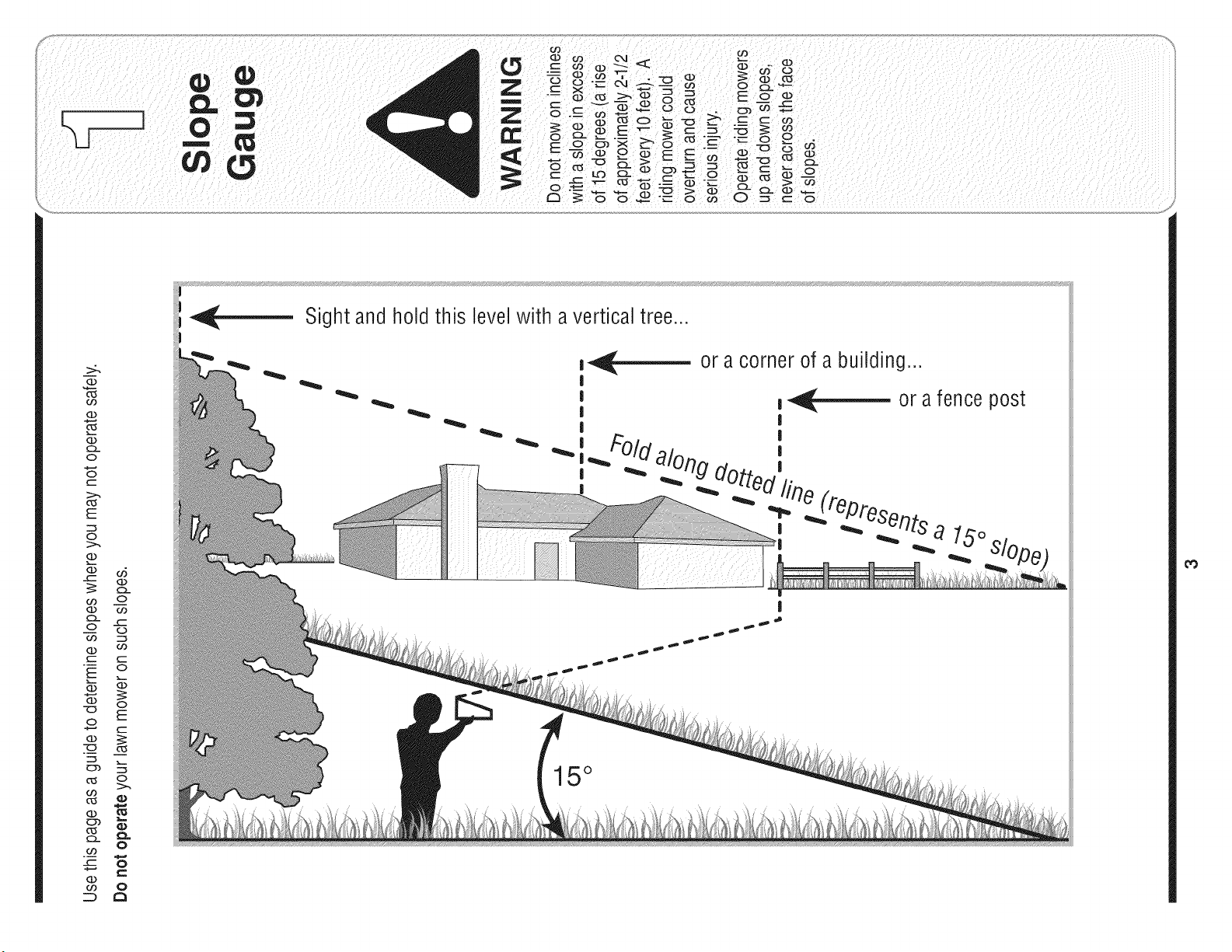
Slope Gauge ........................................................ 3
Safe Operation Practices ................................... 4
Setting UpYour Lawn Tractor ............................ 8
Operating Your Lawn Tractor ........................... 12
Adjusting Your Lawn Tractor ............................ 20
Maintaining Your Lawn Tractor ........................ 22
Off-Season Storage / Attachments ................. 28
Safety Labels .................................................... 29
Troubleshooting ................................................ 30
Replacement Parts ........................................... 32
Finding and Recording Model Number
BEFOREASSEMBLINGYOUR NEW EQUIPMENT,please
locate the model plate on the equipment and copy the
information to the sample model plate provided to the right.
You can locate the model plate by looking under the seat. This
information will be necessary to use the manufacturer's web
site, to obtain assistancefrom the Customer Support Depart-
ment, or when contacting an authorizedservice dealer.
Model Number
www.mtdproducts,com
Serial Number
MTD LLC
P.O= BOX 361131
CLEVELAND, OH 44136
330-220-4683
800-800-7310
Customer Support
Please do NOTreturn the unit to the retailer from which it was
purchased, without first contacting Customer Support.
If you have difficulty assembling this product or have any questions regardingthe controls, operation,or maintenanceof this
unit, you can seek help from the experts. Choose from the options below:
1. Visit www.mtdproducts.com.
2. Phone a Customer Support Representative at 1 (800) 800-7310.
3. The engine manufacturer is responsiblefor all engine-relatedissueswith regards to performance, power-rating,specifica-
tions, warranty and service. Please refer to the engine manufacturer'sOwner's/Operator's Manual, packed separatelywith
your unit, for more information.
2
>:.
G.)
o9
(13
(13
O
O
C
::>.,
E
c_
O
G.)
o6
_-- (13
co .oo
G.) o9
o -_
O9 C:_
G.) O9
C C
_ o
(13
-_ o_
O
C
(13
c_
0
o3
0
C
co 0
_ a
Sight and h01dthis level with a vertical tree..,
m_,_ or a corner of a building...
I
I
__ or a fence post
I
i i
do;
-- fine (repros
I _ _ er_ts a 15o
15°
_0
Operation
WARNING
This symbol points
out important safety
instructionswhich, if
notfollowed, could
i endangerthe personal
safety and/or property
ofyourself and others.
I Readand follow all
i instructions in this man-
i ual before attempting to
i operatethis machine.
Failureto comply with
these instructions may
result in personal injury.
i Whenyou see this
symbol.
i HEED ITS WARNING
Your
i Responsibility
Restrictthe use
of this power machine
I to persons who read,
understand
and follow the warnings
and instructions
in this manual
WARNING: Engine Exhaust,some of its constituents, andcertain vehicle compo-
nents contain or emit chemicals known to State of Californiato cause cancer and
birth defects or other reproductiveharm.
DANGER: This machine was built to be operated according to the rules for safe operation in this
manual. As with any type of power equipment, carelessness or error on the part of the operator can
result in serious injury.This machine is capable of amputating hands and feet and throwing objects.
Failureto observe the followingsafety instructions could result in serious injury or death.
Children
1. Tragicaccidentscanoccurif the operatoris not
alertto the presenceof children.Childrenare often
attractedto themachineandthe mowingactivity.
Theydo not understandthe dangers.Neverassume
thatchildrenwill remainwhereyou lastsawthem.
a. Keepchildrenout of the mowingarea andin
watchfulcare of a responsibleadultother than
the operator.
b. Bealert and turnmachineoff ifa childenters
the area.
c. Beforeandwhile backing,lookbehindand
downfor smallchildren.
d. Nevercarrychildren,evenwiththe blade(s)
shutoff.Theymayfalloff andbe seriously
injuredorinterferewith safemachineoperation.
e. Useextremecarewhenapproachingblind
corners,doorways,shrubs,treesorother
objectsthat mayblockyourvision of a child
whomayrun intothe machine.
f. To avoid back-over accidents, always
disengagethe cuttingblade(s) before
shiftinginto Reverse.If equipped,the
"Reverse CautionMode"shouldnot be
used whenchildrenor others are around.
g. Keepchildrenaway fromhotor running
engines.Theycan sufferburnsfroma hot
muffler.
h. Removekeywhenmachineis unattendedto
preventunauthorizedoperation.
2. Neverallowchildrenunder 14yearsold to operate
the machine.Children14years oldandovershould
readand understandthe operationinstructionsand
safetyrulesinthis manualand shouldbetrainedand
supervisedbya parent.
Operation
Safe Handling of Gasoline:
1. Toavoid personalinjuryor propertydamageuse
extremecare in handlinggasoline.Gasolineis
extremely flammableand the vapors are explo-
sive. Seriouspersonalinjurycan occurwhengasoline
isspilledonyourselfor yourclotheswhichcan ignite.
Washyourskinand changeclothesimmediately.
a. Useonlyan approvedgasolinecontainer.
b. Neverfill containersinsideavehicleor ona
truckor trailerbedwith a plasticliner.Always
placecontainerson the groundawayfrom
yourvehiclebeforefilling.
c. Whenpractical,removegas-powered
equipmentfromthe truckor trailerand refuelit
onthe ground.If this isnotpossible,then
refuelsuchequipmenton a trailerwith a
portablecontainer,ratherthan froma gasoline
dispensernozzle.
d. Keepthe nozzlein contactwiththe rimof
the fueltankor containeropeningat all
timesuntilfuelingiscomplete.Donot usea
nozzlelock-opendevice.
e. Extinguishall cigarettes,cigars,pipesand
othersourcesof ignition.
f. Neverfuel machineindoors.
g. Neverremovegas cap oradd fuel whilethe
engineishot or running.Allowengineto cool
at leasttwo minutesbeforerefueling.
h. Neveroverfill fuel tank.Fill tankto no more
than1/2inchbelowbottomof filler neck to
allowspacefor fuel expansion.
i. Replacegasolinecapand tightensecurely.
j. If gasolineis spilled,wipe it off theengine
andequipment.Moveunit to anotherarea.
Wait5 minutesbeforestartingtheengine.
k. Toreducefirehazards,keepmachinefreeof
grass,leaves,or otherdebris build-up.Clean
upoil or fuel spillageand removeanyfuel
soakeddebris.
I. Neverstorethe machineor fuel container
insidewherethere is an openflame,spark
orpilot lightas on a waterheater,space
heater,furnace,clothesdryeror other gas
appliances.
m. Allowa machineto cool at least fiveminutes
beforestoring.
4
GeneralOperation:
1. Read,understand,andfollowall instructionsonthe
machineandin the manual(s)beforeattemptingto
assembleand operate.Keepthismanualin a safe
placefor futureand regularreferenceandfor ordering
replacementparts.
2. Befamiliarwith all controlsandtheir properoperation.
Knowhow to stopthe machineand disengagethem
quickly.
3, Neverallowchildrenunder14yearsold to operate
this machine.Children14yearsold andovershould
readandunderstandthe operationinstructionsand
safetyrulesin this manualand shouldbetrainedand
supervisedby a parent.
4. Neverallowadultsto operatethis machinewithout
properinstruction.
5. To helpavoidbladecontactor a thrownobjectinjury,
keep bystanders,helpers,childrenand petsat least
75feet fromthe machinewhileit is in operation.Stop
machineif anyoneenters thearea.
6. Thoroughlyinspecttheareawheretheequipmentis to
be used.Removeall stones,sticks,wire,bones,toys,
andotherforeignobjectswhichcouldbe pickedup
andthrown bythe blade(s).Thrownobjectscancause
seriouspersonalinjury.
7. Planyourmowingpatternto avoiddischargeof
materialtowardroads,sidewalks,bystandersandthe
like.Also,avoiddischargingmaterialagainsta wall or
obstructionwhichmaycause dischargedmaterialto
ricochetback towardthe operator.
8. Alwayswear safetyglassesor safetygogglesduring
operationand while performingan adjustmentor
repairto protectyoureyes.Thrownobjectswhich
ricochetcancause seriousinjuryto the eyes.
9. Wearsturdy,rough-soledworkshoesandclose-fitting
slacksand shirts.Loosefittingclothesandjewelry
can becaught inmovableparts.Neveroperatethis
machinein barefeetor sandals.
10.Be awareof the mowerand attachmentdischarge
directionanddo not pointit at anyone.Donot operate
the mowerwithoutthe dischargecoveror entiregrass
catcherin itsproperplace.
11.Donot put handsor feet nearrotatingpartsor under
the cuttingdeck. Contactwiththe blade(s)can
amputatehandsand feet.
12.A missingor damageddischargecovercan cause
bladecontactor thrownobjectinjuries.
13.Stop the blade(s)whencrossinggraveldrives,walks,
or roadsandwhilenot cuttinggrass.
14.Watchfor traffic whenoperatingnearor crossing
roadways.This machineis not intendedfor useon
anypublic roadway.
15.Do notoperatethe machinewhileunderthe influ-
enceof alcoholordrugs.
16.Mowonly in daylightor goodartificiallight.
17.Nevercarry passengers.
18.Disengageblade(s)beforeshiftinginto reverse.
Backup slowly.Alwayslookdownand behindbefore
andwhilebackingto avoida back-overaccident.
19.Slowdownbeforeturning.Operatethe machine
smoothly.Avoiderraticoperationand excessive
speed.
20.Disengageblade(s),set parkingbrake,stopengine
andwait untilthe blade(s)cometo a completestop
beforeremovinggrass catcher,emptyinggrass,
uncloggingchute,removingany grassor debris,or
makinganyadjustments.
21.Neverleavea runningmachineunattended.Always
turnoff blade(s),placetransmissionin neutral,set
parkingbrake,stopengineand removekey before
dismounting.
22.Useextracare whenloadingorunloadingthe
machineintoa trailerortruck. Thisunit shouldnot
bedrivenup or downramp(s),becausethe unit
couldtip over,causingseriouspersonalinjury.The
unit mustbepushedmanuallyon ramp(s)to load or
unloadproperly.
23.Mufflerand enginebecomehotandcan causea
burn.Do nottouch.
24.Checkoverheadclearancescarefullybeforedriving
underlowhangingtreebranches,wires,dooropen-
ingsetc.,wheretheoperatormaybe struckor pulled
fromthe unit,whichcouldresult inseriousinjury.
25.Disengageall attachmentclutches,depressthe
brakepedalcompletelyandshift into neutralbefore
attemptingto startengine.
26.Yourmachineisdesignedto cutnormalresidential
grassof a heightno morethan 10".Do notattemptto
mowthroughunusuallytall,dry grass (e.g.,pasture)
or pilesof dry leaves.Dry grassor leavesmay
contactthe engineexhaustand/orbuild up onthe
mowerdeckpresentinga potentialfire hazard.
27.Use onlyaccessoriesandattachmentsapprovedfor
thismachinebythe machinemanufacturer.Read,
understandandfollowall instructionsprovidedwith
the approvedaccessoryor attachment.
28.Data indicatesthat operators,age60 yearsand
above,are involvedin a largepercentageof riding
mower-relatedinjuries.Theseoperatorsshould
evaluatetheirabilityto operatethe ridingmower
safelyenoughto protectthemselvesand othersfrom
seriousinjury.
29.If situationsoccurwhich arenot coveredin this
manual,usecareandgood judgment.Contactyour
customerservicerepresentativefor assistance.
!i!i ¸¸¸:¸/: :!i¸ ¸¸¸ : :
WARNING
This symbol points
out important safety
instructions which, if
not followed, could
endanger the personal
safety and/or property
of yourself and others.
Readand follow all
instructions in this man-
ual before attempting to
operate this machine.
Failureto comply with
these instructionsmay
result in personal injury.
When you see this
symbol.
HEED ITS WARNING
Your
Responsibility
Restrictthe use
of this power machine
to persons who read,
understand
and follow the warnings
and instructions
in this manual
5
Operation
This symbol points
out important safety
instructions which, if
notfollowed, could
endangerthe personal
i safety and/or property
of yourself and others.
Read and follow all
=nstructionsin this man-
ual before attempting to
I operate this machine.
I Failureto comply with
i these instructions may
i result in personal injury.
When you see this
symbol.
HEED ITS WARNING
Your
Responsibility
Restrictthe use
of this power machine
to persons who read,
understand
and follow the warn=ngs
and instructions
in this manual
Slopesare a majorfactor relatedto lossof controland
tip-overaccidentswhichcan resultin severeinjuryor
death.All slopesrequireextracaution.If youcannot
backup the slopeor if youfeel uneasyon it, do notmow
it.
Foryour safety,usethe slopegaugeincludedas partof
thismanualto measureslopesbeforeoperatingthis unit
ona slopedor hillyarea. If the slopeis greaterthan 15
degreesas shownon theslopegauge,do notoperate
thisunit on thatarea or seriousinjurycouldresult.
DO:
1. Mowup anddownslopes,notacross.Exercise
extremecautionwhenchangingdirectiononslopes.
2. Watchfor holes, ruts,bumps,rocks,orother hidden
objects.Uneventerraincouldoverturnthe machine.
Tallgrasscan hideobstacles.
3. Useslow speed.Choosea low enoughspeed
settingso thatyouwill not haveto stopor shift while
onthe slope.Tires maylosetractionon slopeseven
thoughthe brakesare functioningproperly.Always
keepmachineingear whengoingdown slopesto
takeadvantageof enginebrakingaction.
4. Followthe manufacturer'srecommendationsfor
wheelweightsor counterweightsto improvestability.
5. Useextracare with grasscatchersorotherat-
tachments.Thesecanchangethe stabilityof the
machine.
6. Keepall movementon the slopesslowand gradual.
Do not makesuddenchangesin speedor direction.
Rapidengagementor brakingcouldcausethe front
of the machineto liftand rapidlyflip overbackwards
whichcouldcauseseriousinjury.
7. Avoidstartingor stoppingon a slope.If tireslose
traction,disengagethe blade(s)and proceedslowly
straightdownthe slope.
Do Not:
1. Do notturn on slopesunlessnecessary;then,turn
slowlyandgraduallydownhill,if possible.
2. Do not mowneardrop-offs,ditchesor embankments.
Themowercouldsuddenlyturnoverif awheel is over
the edgeof a cliff,ditch,or if an edgecavesin.
3. Do nottry to stabilizethe machineby puttingyourfoot
onthe ground.
4. Do not usea grasscatcheronsteep slopes.
5. Do not mowonwet grass. Reducedtractioncould
causesliding.
6. Do not shiftto neutralandcoastdownhill.Over-speed-
ingmay causethe operatorto losecontrol of the
machineresultingin seriousinjuryordeath.
7. Do nottow heavypullbehindattachments(e.g.loaded
dumpcart, lawnroller,etc.)on slopesgreaterthan
5 degrees.Whengoingdown hill,the extraweight
tendsto pushthe tractorand maycauseyou to loose
control.(e.g. tractormayspeedup, brakingand steer-
ingability arereduced,attachmentmayjack-knifeand
causetractorto overturn).
Towing:
1. Towonlywitha machinethat hasa hitchdesignedfor
towing.Donot attachtowedequipmentexceptat the
hitchpoint.
2. Followthe manufacturersrecommendationfor weight
limitsfor towedequipmentandtowingon slopes.
3. Neverallowchildrenor othersin oron towedequip-
ment.
4. Onslopes,the weightof the towedequipmentmay
causelossof tractionand lossof control.
5. Travelslowlyandallowextra distanceto stop.
6. Do not shiftto neutralandcoastdownhill.
6
Service
1. Neverrunan engineindoorsorin a poorlyventilated
area. Engineexhaustcontainscarbonmonoxide,an
odorless,and deadlygas.
2. Beforecleaning,repairing,or inspecting,makecertain
the blade(s)andall movingparts havestopped.
Disconnectthe sparkplug wireandgroundagainstthe
engineto preventunintendedstarting.
3. Periodicallycheckto make surethe bladescome to
completestop withinapproximately(5) five seconds
afteroperatingthe bladedisengagementcontrol.Ifthe
bladesdo notstopwithin thethis timeframe,yourunit
shouldbe servicedprofessionallyby anauthorized
MTDServiceDealer.
4. Checkbrakeoperationfrequentlyas it is subjectedto
wearduringnormaloperation.Adjustand serviceas
required.
5. Checkthe blade(s)andenginemountingbolts at
frequentintervalsfor propertightness.Also,visually
inspectblade(s)for damage(e.g.,excessivewear,
bent,cracked). Replacethe blade(s)with theoriginal
equipmentmanufacturer's(O.E.M.)blade(s)only,
listedinthis manual."Useof partswhich donot meet
the originalequipmentspecificationsmayleadto
improperperformanceandcompromisesafety!"
6. Mowerbladesaresharp.Wrapthe bladeor wear
gloves,anduseextra cautionwhenservicingthem.
7. Keepallnuts, bolts,and screwstightto besurethe
equipmentis insafeworkingcondition.
8. Nevertamperwiththe safety interlocksystemor other
safetydevices.Checktheir properoperationregularly.
9. Afterstrikinga foreignobject,stopthe engine,
disconnectthe sparkplug wire(s)andgroundagainst
the engine.Thoroughlyinspectthe machinefor any
damage.Repairthe damagebeforestartingand
operating.
10.Neverattemptto makeadjustmentsor repairsto the
machinewhilethe engineisrunning.
11.Grasscatchercomponentsandthe discharge
coveraresubjectto wearand damagewhich could
exposemovingpartsor allowobjectsto bethrown.
Forsafetyprotection,frequentlycheckcomponents
andreplaceimmediatelywithoriginalequipment
manufacturer's(O.E.M.)partsonly,listed inthis
manual."Useof partswhich donot meetthe original
equipmentspecificationsmay leadto improper
performanceandcompromisesafety!"
12.Do notchangethe enginegovernorsettingsor
over-speedthe engine.Thegovernorcontrolsthe
maximumsafeoperatingspeedof the engine.
13.Maintainor replacesafety andinstructionlabels,as
necessary.
14.Observeproperdisposallawsand regulationsfor
gas,oil,etc. to protecttheenvironment.
7
This symbol points
out important safety
instructions which, if
not followed, could
endangerthe personal
safety and/or property
of yourself and others.
Read and follow all
instructions in this man-
ual before attempting to
operatethis machine.
Failureto comply with
these instructions may
result in personal injury.
When you see this
symbol.
HEED iTS WARNING
Your
Responsibility
Restrictthe use
of this power machine
to personswho read,
understand
and follow the warn=ngs
and instructions
in this manual
Use extreme care
henhandling
gaso nelGasoline
extremely flammable
and the vapors are
explosive: Never fuel
machine indoors
or while the engine
is hot or running:
Extinguish cigarettes,
cigars;pipes,and
other sOurceS of
ignition:
NOTE: This Operators
Manual Coversa range
of prOduCtSpecifications
for various models.
Characteristicsand
features disCussed
and/or illustrated
this manual may not be
I
applicable to all modelsl
MTD LLC reservesthe
right tOchange product
specifiCationsldesigns
and equipment without
notice and without incur-
ting oblieation ,,
NOTE:This OperatorsManualcoversa rangeof prod-
uctspecificationsfor variousmodels.Characteristics
andfeaturesdiscussedand/or illustratedin thismanual
maynot be applicableto allmodels.MTDLLCreserves
the rightto changeproductspecifications,designs
andequipmentwithoutnoticeand withoutincurring
obligation.
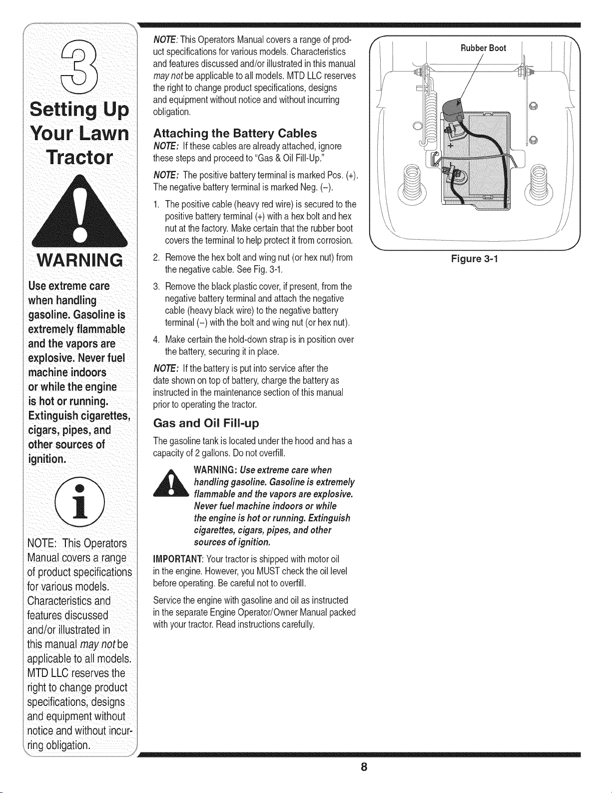
Attaching the Battery Cables
NOTE: If thesecablesarealreadyattached,ignore
thesestepsand proceedto "Gas& Oil Fill-Up."
NOTE: Thepositivebatteryterminalis markedPos. (+).
Thenegativebatteryterminalis markedNeg.(-).
.
.
Thepositivecable(heavyredwire) is securedto the
positivebatteryterminal(+)with a hexbolt and hex
nut at thefactory.Makecertainthatthe rubberboot
coversthe terminalto help protectit fromcorrosion.
Removethehex boltand wing nut (or hex nut)from
the negativecable.See Fig.3-1.
Removetheblack plasticcover,ifpresent,fromthe
negativebatteryterminalandattachthe negative
cable(heavyblackwire)to the negativebattery
terminal(-) withthe bolt and wing nut(or hexnut).
4. Makecertainthehold-downstrapis in positionover
the battery,securingit in place.
NOTE: If the batteryis putinto serviceafterthe
dateshownon topof battery,chargethe batteryas
instructedin the maintenancesectionof thismanual
priorto operatingthe tractor.
Gas and Oil Fill-up
Thegasolinetank is locatedunderthe hood andhasa
capacityof 2 gallons.Do notoverfill.
_ WARNING:Use extreme care when
handling gasoline. Gasolineis extremely
flammable and the vapors are explosive.
Neverfuel machine indoors or while
the engine is hot or running. Extinguish
cigarettes, cigars, pipes, and other
sources of ignition.
IMPORTANT:Yourtractoris shippedwith motoroil
in theengine.However,you MUSTcheckthe oil level
beforeoperating.Be carefulnotto overfill.
Servicethe enginewithgasolineandoil as instructed
in theseparateEngineOperator/OwnerManualpacked
withyourtractor.Readinstructionscarefully.
Rubber Boot
Figure 3=1
8
f _ Shipping Brace Removal
WARNING:Makesure the riding mower's
engine is off, removethe ignition key,and
set the parking brake before removing the
shipping brace.
Locatethe shippingbrace,if present,andaccom-
panyingwarningtag foundonthe right sideof the
mower,betweenthe dischargechute andthecutting
deck.SeeFig. 3-2.
Whileholdingthe dischargechutewithyour left
hand,removethe shippingbracewith your right
handbygraspingit betweenyour thumband index
fingerandrotatingit clockwise.
\ j
Figure 3=2
f
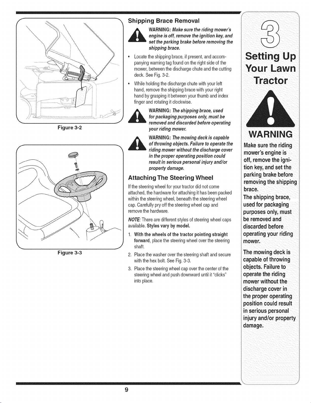
Figure 3-3
WARNING:Theshipping brace, used
for packaging purposes only, must be
removedand discarded before operating
your riding mower.
WARNING:Themowing deck is capable
of throwing objects. Failure to operate the
riding mower without the discharge cover
in the proper operating position could
result in serious personal injury and/or
property damage.
Attaching The Steering Wheel
If the steeringwheelfor yourtractordidnot come
attached,the hardwareforattachingithas beenpacked
withinthe steeringwheel,beneaththe steeringwheel
cap.Carefullypryoff the steeringwheelcap and
removethe hardware.
NOTE:Thereare differentstylesof steeringwheelcaps
available.Styles vary by model.
.
With the wheels of the tractor pointingstraight
forward, placethe steeringwheeloverthe steering
shaft.
2. Placethewasheroverthe steeringshaftand secure
withthe hexbolt. See Fig.3-3.
3. Placethe steeringwheelcap overthecenter of the
steeringwheeland pushdownwarduntilit "clicks"
into place.
Setting Up
WARNING
Make sure the riding
mower's engine is
off, remove the igni-
tion key, and set the
parking brake before
removing the shipping
brace.
The shipping brace,
used for packaging
purposes only, must
be removed and
discarded before
operating your riding
mower.
The mowing deck is
capable of throwing
objects. Failure to
operate the riding
mower without the
discharge cover in
the proper operating
positioncould result
in serious personal
injury and/or property
damage.
9
WARNING
Before operating this
machine, make sure
the seat is engaged in
the seat stop, stand
behind the machine
and pull back on seat
until fully engaged
into stop.
/
Attaching The Seat
Seatstylesvary bytractormodelandthereare three
differentstyles available:
• StandardAdjustment
QuickAdjustment&
• KnobAdjustment
If the seatfor yourtractordid notcomeattached,
referto Fig.3-4, Fig. 3-5, and Fig.3-6 to identifyyour
tractor'sseatstyle andfollowthe applicableinstructions
belowto attachit.
NOTE:Forshippingreasons,seatsareeitherfastened
to the tractorseat'spivot bracketwith a plastictie,or
mountedbackwardto the pivot bracket.Ineithercase,
freethe seatfrom itsshippingpositionand removethe
twohex screws(or knobs,on modelsso equipped)from
the bottomof seatbeforeproceedingwithapplicable
instructionsbelow.
f
Figure 3-4
f
x.............................................................................
J
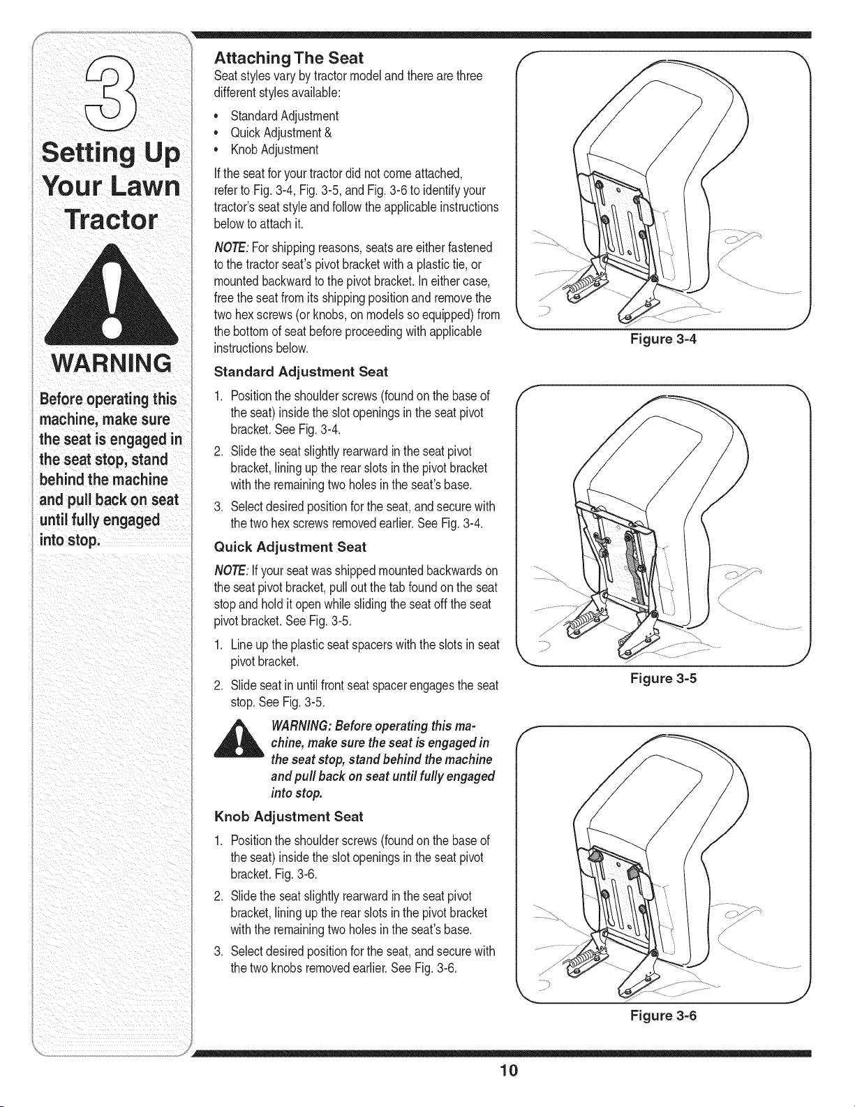
Standard Adjustment Seat
1. Positionthe shoulderscrews(foundon the baseof
the seat)insidethe slot openingsin the seat pivot
bracket.SeeFig.3-4.
2. Slidethe seatslightlyrearwardinthe seatpivot
bracket,liningupthe rearslots inthe pivot bracket
withthe remainingtwo holesinthe seat'sbase.
3. Selectdesiredpositionforthe seat,and securewith
the twohex screwsremovedearlier.SeeFig.3-4.
Quick Adjustment Seat
NOTE:If your seatwas shippedmountedbackwardson
the seatpivotbracket,pull outthe tab foundon the seat
stopand holditopen whileslidingthe seatoff the seat
pivotbracket.See Fig.3-5.
f
1. Lineup the plasticseat spacerswith the slotsin seat .................,
pivotbracket.
2. Slideseat inuntilfrontseat spacerengagesthe seat
stop.SeeFig. 3-5.
_ ARNING: Before operating this ma-chine, makesure the seat is engaged in
the seat stop, stand behind the machine
and pull back on seat until fully engaged
into stop.
Knob Adjustment Seat
1. Positionthe shoulderscrews(foundon the baseof
the seat)insidethe slot openingsin the seat pivot
bracket.Fig.3-6.
2. Slidethe seatslightlyrearwardinthe seatpivot
bracket,liningupthe rearslots inthe pivot bracket
withthe remainingtwo holesinthe seat'sbase.
3. Selectdesiredpositionforthe seat,and securewith
the twoknobs removedearlier.See Fig.3-6.
Figure 3=5
f
x............................_................................................
J
Figure 3=6
10
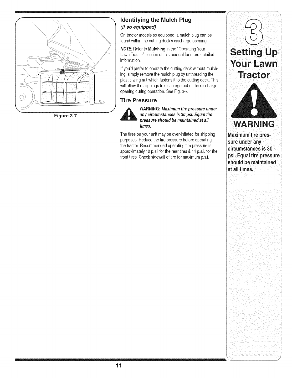
Figure 3-7
identifying the Mulch Plug
(if so equipped)
Ontractormodelsso equipped,a mulchplug can be
foundwithinthe cuttingdeck'sdischargeopening.
NOTE:Referto Mulching inthe "OperatingYour
LawnTractor"sectionof this manualfor moredetailed
information.
If you'dpreferto operatethe cuttingdeck withoutmulch-
ing, simplyremovethe mulchplugby unthreadingthe
plasticwingnut whichfastensit to the cuttingdeck. This
willallow theclippingsto dischargeoutof the discharge
openingduringoperation.See Fig.3-7.
Tire Pressure
,_ WARNING:Maximum tire pressure under
any circumstances is 30psi. Equal tire
pressure should be maintained at all
times.
Thetireson yourunit maybe over-inflatedfor shipping
purposes.Reducethe tire pressurebeforeoperating
the tractor.Recommendedoperatingtire pressureis
approximately10 p.s.iforthe reartires& 14 p.s.i,for the
fronttires. Checksidewallof tire for maximump.s.i.
11
Your LaWn
Tractor
WARNING
Ma,, mumt repres'
sure under any
circumstances is 30
psi: Equal tire pressure
should be maintained
atalltimesl
NOTE:Any reference
in this manual to the
RIGHTor LEFT side of
the tractor is observed
from operator's position.
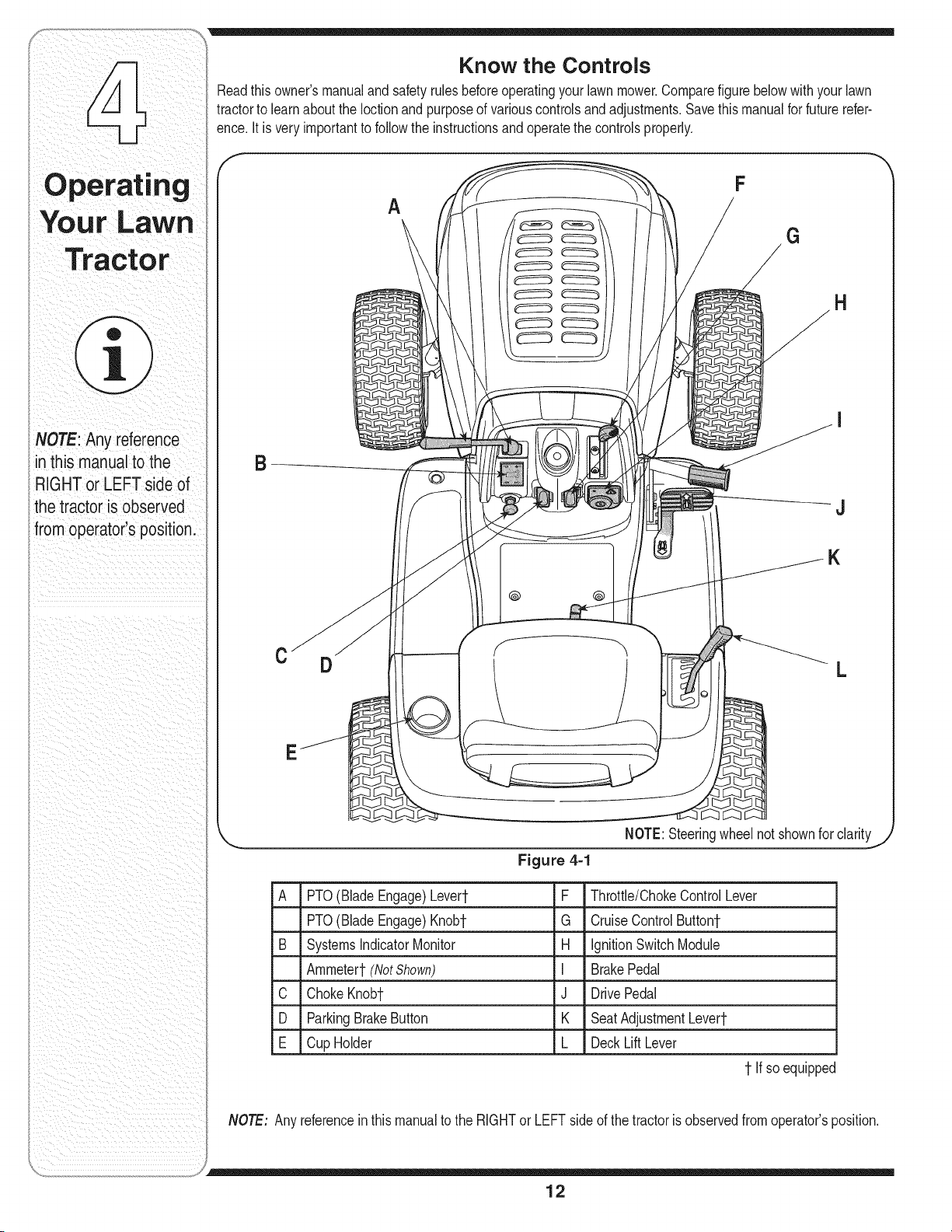
Know the Controls
Readthisowner'smanualand safetyrulesbeforeoperatingyourlawnmower.Comparefigurebelowwith yourlawn
tractorto learnaboutthe Ioctionand purposeof variouscontrolsandadjustments.Savethis manualfor futurerefer-
ence.It is veryimportantto followthe instructionsandoperatethe controlsproperly.
f
F
A
G
H
B
J
@ @
K
C
D
S
L
NOTE:Steeringwheelnot shownfor clarityj
Figure 4=1
A PTO(Blade Engage)Levert F Throttle/ChokeControlLever
PTO(BladeEngage)Knobt G CruiseControlButtont
B SystemsIndicatorMonitor H IgnitionSwitchModule
Ammeter1-(NotShown) I BrakePedal
C ChokeKnobt J DrivePedal
D ParkingBrakeButton K SeatAdjustmentLevert
E Cup Holder L DeckLift Lever
1-Ifso equipped
NOTE: Any referenceinthis manualto the RIGHTor LEFTsideof the tractoris observedfromoperator'sposition.
12
m
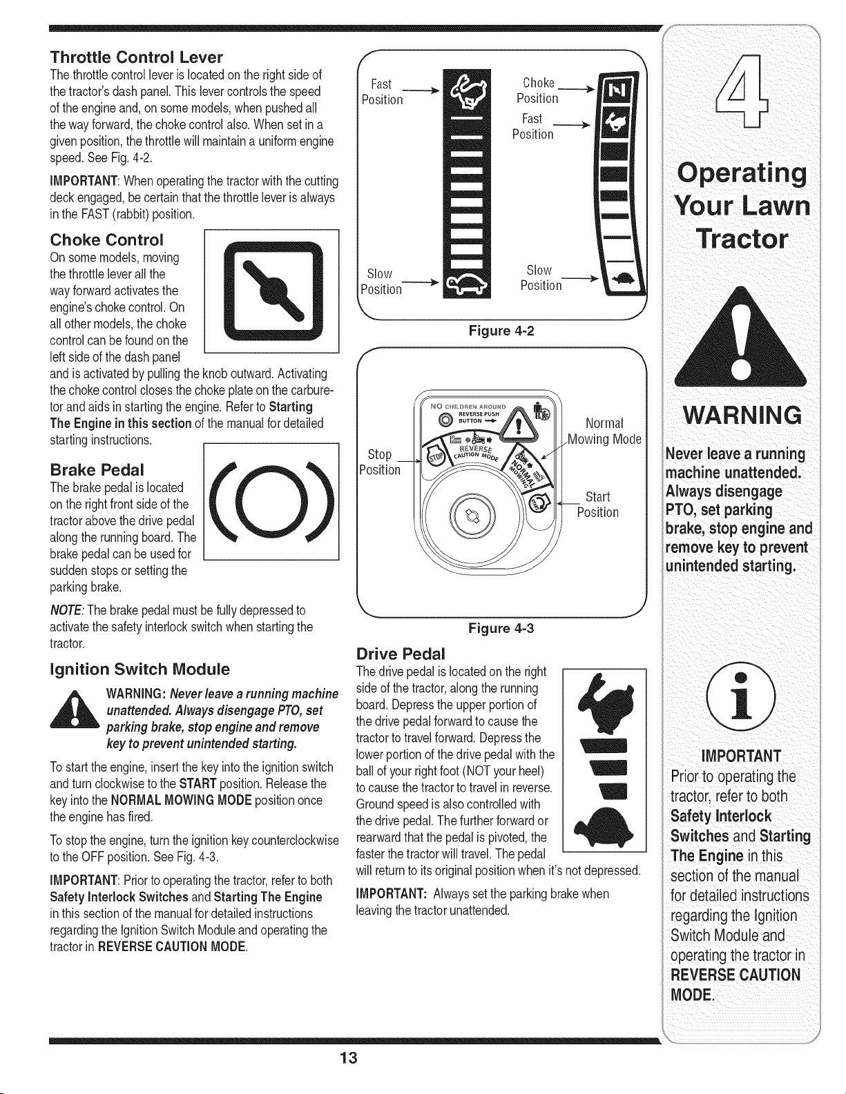
Throttle Control Lever
Thethrottlecontrolleveris locatedon the rightside of
thetractor'sdash panel.This levercontrolsthe speed
of the engineand,on somemodels,when pushedall
thewayforward,the chokecontrolalso.Whenset ina
givenposition,the throttlewill maintaina uniformengine
speed.SeeFig. 4-2.
IMPORTANT:Whenoperatingthetractorwith the cutting
deckengaged,becertainthat the throttleleverisalways
inthe FAST(rabbit)position.
Choke Control
Onsome models,moving
thethrottle leverall the
wayforwardactivatesthe
engine'schoke control.On
allother models,the choke
controlcan befoundon the
leftside of the dashpanel
andis activatedby pullingthe knob outward.Activating
thechokecontrolclosesthe chokeplateon the carbure-
tor andaidsin startingtheengine.Referto Starting
The Engine inthis section of the manualfor detailed
startinginstructions.
Brake Pedal
The brakepedal islocated
onthe rightfront side of the
tractorabovethe drivepedal
alongthe runningboard.The
brakepedalcan beusedfor
suddenstopsor settingthe
parkingbrake.
NOTE:Thebrakepedal mustbefully depressedto
activatethe safetyinterlockswitchwhenstartingthe
tractor.
ignition Switch Module
_ ARNING:Neverleave a running machine
unattended. Always disengage PTO,set
parking brake,stop engine and remove
key to prevent unintended starting.
Tostart theengine,insertthe keyintothe ignitionswitch
andturnclockwiseto the STARTposition.Releasethe
keyintothe NORMALMOWINGMODEpositiononce
theenginehasfired.
Tostopthe engine,turn theignitionkeycounterclockwise
to the OFFposition.SeeFig. 4-3.
IMPORTANT:Priorto operatingthetractor,referto both
Safety Interlock Switches and Starting The Engine
inthis sectionof the manualfordetailedinstructions
regardingthe IgnitionSwitchModuleand operatingthe
tractorinREVERSECAUTIONMODE.
F
Fast
Position
Slow
Position
Choke
Position
Fast
Position
Slow
Position
F
Position
Figure 4=2
Normal
Mode
Start
Position
Figure 4=3
Drive Pedal
The drivepedalis locatedon the right
sideof the tractor,alongthe running
board.Depressthe upper portionof
the drivepedalforwardto causethe
tractorto travelforward.Depressthe
lowerportionof the drivepedalwith the
ballof yourrightfoot(NOT yourheel)
to causethetractorto travel in reverse.
Groundspeedis alsocontrolledwith
the drivepedal.Thefurtherforwardor
rearwardthatthe pedal is pivoted,the
fasterthe tractorwill travel.Thepedal
I
M
W
,ib
will returnto itsoriginal positionwhen it's notdepressed.
IMPORTANT:Alwayssetthe parkingbrakewhen
leavingthetractorunattended.
13
WAn.I.G
Never leave a running
machine unattended.
Always disengage
PTO,set parking
brake, stop engine and
remove keyto prevent
unintended starting;
iMPORTANT
Prioriooperatingthe
tractorl referto both
Safety Interlock
Switches and Starting
The Engine inthis
section ofthe manual
for detailed instructions
regarding the Ignition
Switch Moduleand
operating the tractor ir
NOTE:ThePTO(Blade
Engage)knobmustbe
inthedisengaged(OFF)
positionwhenstarting
theengine,when
travelingin reverseand
iftheoperatorleaves
theseat.
NOTE:ThePTO(Blade
Engage)levermustbe
inthedisengaged(OFF)
positionwhenstarting
theengine,when
travelinginreverseand
iftheoperatorleaves
theseat.
\-_ BATT, OIL zZ
I 42.0
/// HOURS 1/1 0 \\\
PTO/ BLADE PARKING
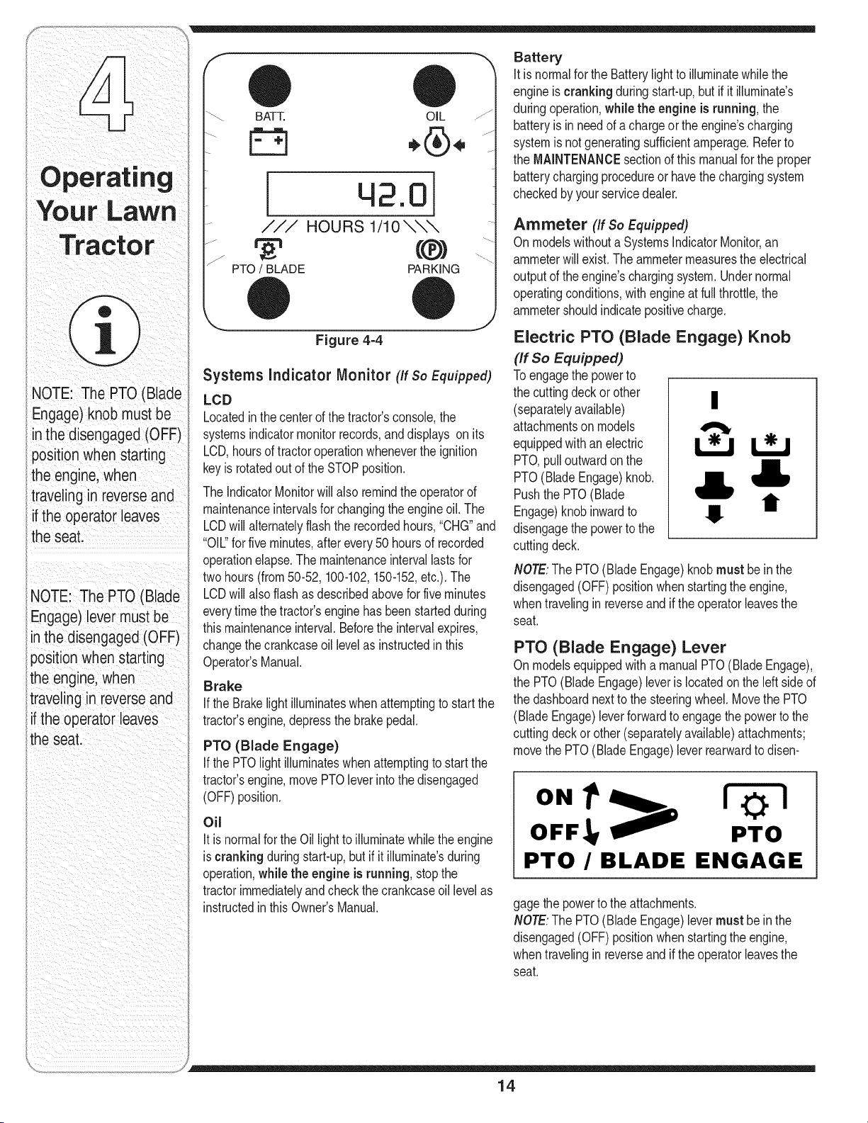
Figure 4-4
Systems Indicator Monitor (If so Equipped)
LCD
Locatedinthe centerof the tractor'sconsole,the
systemsindicatormonitorrecords,and displays on its
LCD,hoursof tractoroperationwheneverthe ignition
keyis rotatedout of the STOPposition.
The IndicatorMonitorwill also remindthe operatorof
maintenanceintervalsfor changingthe engineoil. The
LCDwill alternatelyflashthe recordedhours,"CHG"and
"OIL"for five minutes,afterevery50 hoursof recorded
operationelapse.The maintenanceintervallastsfor
twohours(from 50-52,100-102,150-152,etc.). The
LCDwill alsoflashas describedabovefor fiveminutes
everytimethe tractor'sengine hasbeenstartedduring
thismaintenanceinterval.Beforethe intervalexpires,
changethe crankcaseoil levelas instructedin this
Operator'sManual.
Brake
If the Brakelight illuminateswhenattemptingto start the
tractor'sengine,depressthe brakepedal.
PTO (Blade Engage)
If the PTOlightilluminateswhenattemptingto start the
tractor'sengine,movePTOleverintothe disengaged
(OFF)position.
Oil
It is normalforthe Oil lightto illuminatewhilethe engine
is crankingduringstart-up,but if it illuminate'sduring
operation,while the engine is running,stopthe
tractorimmediatelyand checkthe crankcaseoillevelas
instructedin thisOwner'sManual.
Battery
It is normalfor the Batterylightto illuminatewhile the
engineis crankingduring start-up,but if it illuminate's
duringoperation,while the engine is running, the
batteryis in needof a chargeorthe engine'scharging
systemis not generatingsufficientamperage.Referto
the MAINTENANCEsectionof this manualfor the proper
batterychargingprocedureor havethechargingsystem
checkedby yourservicedealer.
Ammeter (If so Equipped)
Onmodelswithouta SystemsIndicatorMonitor,an
ammeterwill exist. Theammetermeasuresthe electrical
outputof the engine'schargingsystem.Undernormal
operatingconditions,with engineat full throttle,the
ammetershouldindicatepositivecharge.
Electric PTO (Blade Engage) Knob
(If So Equipped)
Toengagethe powerto
the cuttingdeck or other
(separatelyavailable) II
attachmentson models
equippedwithan electric I_
PTO,pulloutwardon the
PTO(BladeEngage)knob.
Pushthe PTO(Blade
Engage)knobinwardto
disengagethe powerto the
cuttingdeck.
t/
II
NOTE:The PTO(Blade Engage)knobmust bein the
disengaged(OFF)positionwhen startingthe engine,
whentravelingin reverseand if the operatorleavesthe
seat.
PTO (Blade Engage) Lever
Onmodelsequippedwith a manualPTO(Blade Engage),
the PTO(BladeEngage)leveris locatedon the left sideof
the dashboardnextto the steeringwheel.Movethe PTO
(BladeEngage)leverforwardto engagethe powerto the
cuttingdeckor other(separatelyavailable)attachments;
movethe PTO(BladeEngage)leverrearwardto disen-
ON1 z
OFF, PTO
PTO /BLADE ENGAGE
gagethepowerto the attachments.
NOTE:The PTO(Blade Engage)levermust be in the
disengaged(OFF)positionwhen startingthe engine,
whentravelingin reverseand if the operatorleavesthe
seat.
14
Seat Adjustment Lever (If so Equipped)
Toadjustthe seatforwardor backwardon unitsequipped
witha quick-adjustseat,slidethe seatadjustmentlever
to the leftand repositionthe seatto the desiredposition.
Oncea comfortablepositionis found,releasethe seat
adjustmentleverto lock the seatin place.Referto the
AdjustingYourLawnTractorsectionof this manualfor
moredetailedinstructionson all seatadjustments.
Deck Lift Lever
Foundon yourtractor'srightfender,the decklift leveris
usedto changetheheightof the cuttingdeck.To use,
movethe leverto the left,then placein the notchbest
suitedfor yourapplication.
Parking Brake Button
Tosetthe parkingbrake,fully
depressthe brakepedal and
pushthe parkingbrakebutton
in.Holdthe buttoninwhile
takingyourfootoff the brake
pedal.Boththe parkingbutton
andthe brakepedalwill then
staydepressed.To release
the parkingbrake,depressthe
brakepedalslightly.Theparking
brakebuttonwill then returnto
itsoriginal position.
NOTE:Theparkingbrakemustbeset if theoperator
leavesthe seatwiththe engine runningor theenginewill
automaticallyshutoff.
iMPORTANT:Alwaysset the parkingbrakewhen leaving
thetractor unattended.
Cruise Control Button
Thecruisecontrolbutton is
locatedonthe tractordashpanel
to the leftof the ignitionswitch.
Pushthe cruisecontrolbutton
whiletravelingforwardat a
desiredspeed.Whileholdingthe
buttonin, releasepressurefrom
thedrive pedal.Thiswill engage
thecruisecontroland allowthe
tractorto remainat that speed
withoutapplyingpressureto the
drivepedal.Depressthe brake
pedalor the drivepedalto deactivatecruisecontrol.
Referto Setting the Cruise Control laterinthis section
the manualfor detailedinstructionsregardingthecruise
controlfeature.
Safety Interlock Switches
Thistractoris equippedwith a safetyinterlocksystem
for the protectionof the operator.Ifthe interlocksystem
shouldevermalfunction,do notoperatethe tractor.
Contactan authorizedMTDservicedealer.
• The safetyinterlocksystempreventsthe engine
fromcrankingor startingunlessthe parkingbrake
isengaged,and the PTO(Blade Engage)knob (or
lever)isin the disengaged(OFF)position.
• The enginewill automaticallyshutoff if the operator
leavesthe seatbeforeengagingtheparkingbrake.
Models with Manual PTO (Blade Engage)
• The enginewill automaticallyshutoff if the operator
leavesthe tractor'sseatwiththe PTO(Blade Engage)
leverin the engaged(ON) position,regardlessof
whetherthe parkingbrakeisengaged.
• With the ignitionkeyinthe NORMALMOWING
position,the enginewill automaticallyshut off if the
PTO(Blade Engage)leveris movedinto theengaged
(ON)positionwiththe drivepedal in Reverse.
Models with Electric PTO (Blade Engage)
• The electricPTO(BladeEngage)clutchwillautomati-
callyshut off if the operatorleavesthetractor'sseat
withthe PTO(Blade Engage)knob in the engaged
(ON)position,regardlessof whetherthe parking
brakeis engaged.
• With the ignitionkey inthe NORMALMOWING
position,the electricPTO(Blade Engage)clutchwill
automaticallyshutoff if the PTO(Blade Engage)knob
is movedintothe engaged(ON) positionwiththe
drivepedalleverin Reverse.
,_ WARNING:Do not operate the tractor if the
interlock system is malfunctioning. This
system was designed for your safety and
protection.
NOTE:Cruisecontrolcan NOTbe engagedat the
tractor'sfastestgroundspeed.If the operatorshould
attemptto doso, the tractorwill automaticallydecelerate
to the fastestoptimalmowinggroundspeed.
Tractol
WARNING
Do not operate the
tractor if the interlock
system is malfunction-
ing. This system was
designed for your
safety and protection.
15
WARNING
Use extreme caution
while operating
the tractor in the
REVERSE CAUTION
MODE. Always look
down and behind
before and while
backing. Do not oper-
ate the tractor when
children or others
are around. Stop the
tractor immediately if
someone enters the
area.
Keep hands and feet
away from the dis-
charge opening of the
cutting deck.
Do not operate the
tractor if the interlock
system is malfunction-
ing. This system was
designed for your
safety and protection.
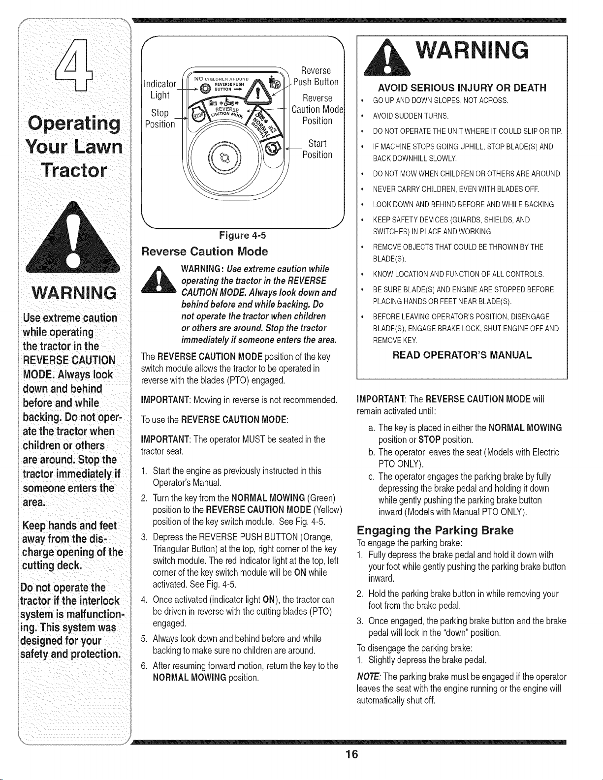
f
indicator
Light
Stop
Position
©
Reverse
.Push Button
Reverse
Caution Mode
Position
Start
Position
Figure 4=5
Reverse Caution Mode
_ ARNING:Useextreme caution while
operating the tractor in the REVERSE
CAUTIONMODE.Always look down and
behind before and while backing. Do
not operate the tractor when children
or others are around. Stop the tractor
immediately if someone enters the area.
The REVERSECAUTIONMODEpositionof the key
switchmoduleallowsthe tractorto be operatedin
reversewiththe blades(PTO)engaged.
IMPORTANT:Mowingin reverseis not recommended.
Tousethe REVERSECAUTIONMODE:
IMPORTANT:TheoperatorMUSTbe seatedin the
tractorseat.
1. Startthe engineas previouslyinstructedinthis
Operator'sManual.
2. Turnthe key fromthe NORMALMOWING(Green)
positionto the REVERSECAUTIONMODE(Yellow)
positionof the keyswitchmodule. See Fig.4-5.
3. Depressthe REVERSEPUSHBUTTON(Orange,
TriangularButton)at the top, rightcornerof the key
switchmodule.The redindicatorlight at thetop, left
cornerof the keyswitch modulewill be ON while
activated.See Fig.4-5.
4. Onceactivated(indicatorlightON), thetractorcan
bedrivenin reversewith the cuttingblades(PTO)
engaged.
5. Alwayslookdownand behindbeforeand while
backingto makesureno childrenare around.
6. Afterresumingforwardmotion,returnthe keyto the
NORMALMOWINGposition.
, WA
AVOID SERIOUS INJURY OR DEATH
• GO UP AND DOWNSLOPES,NOT ACROSS.
• AVOID SUDDENTURNS.
• DO NOT OPERATETHE UNIT WHERE IT COULDSLIP OR TIR
• IF MACHINESTOPSGOINGUPHILL,STOP BLADE(S) AND
BACK DOWNHILLSLOWLY.
• DO NOT MOWWHEN CHILDRENOR OTHERSARE AROUND.
• NEVER CARRYCHILDREN,EVENWITH BLADESOFR
• LOOK DOWNAND BEHINDBEFOREAND WHILEBACKING.
• KEEP SAFETY DEVICES(GUARDS,SHIELDS,AND
SWITCHES)IN PLACE ANDWORKING.
• REMOVEOBJECTSTHATCOULD BETHROWNBYTHE
BLADE(S).
• KNOW LOCATIONAND FUNCTIONOF ALL CONTROLS.
• BE SUREBLADE(S) AND ENGINEARE STOPPEDBEFORE
PLACING HANDSOR FEET NEAR BLADE(S).
• BEFORE LEAVINGOPERATOR'SPOSITION,DISENGAGE
BLADE(S), ENGAGEBRAKE LOCK, SHUTENGINE OFF AND
REMOVEKEY.
READ OPERATOR'S MANUAL
IMPORTANT:The REVERSECAUTIONMODEwill
remainactivateduntil:
a. The keyis placedin eitherthe NORMALMOWING
positionor STOPposition.
b. Theoperatorleavesthe seat (ModelswithElectric
PTOONLY).
c. Theoperatorengagesthe parkingbrakebyfully
depressingthe brakepedal andholdingit down
whilegentlypushingthe parkingbrakebutton
inward(Modelswith ManualPTOONLY).
Engaging the Parking Brake
Toengagethe parkingbrake:
1. Fullydepressthe brakepedalandhold it downwith
yourfootwhilegently pushingthe parkingbrakebutton
inward.
2. Holdthe parkingbrakebutton inwhile removingyour
footfromthe brakepedal.
3. Onceengaged,the parkingbrakebuttonandthe brake
pedalwill lockin the "down"position.
Todisengagetheparkingbrake:
1. Slightlydepressthe brakepedal.
NOTE:Theparkingbrakemustbe engagedif the operator
leavesthe seatwiththe engine runningor theenginewill
automaticallyshutoff.
16
Setting the Cutting Height 2. Turnthe ignitionkey counterclockwiseto the STOP
1 Seecttheheghtpostonofthecuttngdeckby _ position. ............ //I I
' . .... _ Hemovetne KeyTromtnegn t on swtch to prevent
placingthe deck hftleverin any of the six different ' . . /Z_ h
.... unntendedstart ng
cuttingheightnotcheson the nght sideof the fender.
2. Adjustthe deckwheelsso that theyarebetween Driving The Tractor
_A-inchand_/2-inchabovethegroundwhenthetractor
is ona smooth,flat surfacesuchas a driveway.
,_ WARNING:Keephands and feetawayfrom
the discharge opening of the cutting deck.
NOTE:Thedeck wheelsarean anti-scalpfeatureof the
deckand arenot designedto supportthe weightof the
cuttingdeck.
RefertoLevelingtheDeckonpage20ofthismanualformore
detailedinstructionsregardingvariousdeckadjustments.
,_ WARNING:Avoid sudden starts, ex-ces-
sive speed and sudden stops.
WARNING:Do not leave the seat of the
tractor without first placing the PTO(Blade
Engage)knob (or lever) in the disengaged
(OFF)position, depressing the brake pedal
and engaging the parking brake./f leaving
the tractor unattended, also turn the
ignition key off and remove the key.
Starting the Engine
_ ARNING:Do not operate the tractor if
the interlock system is malfunctioning.
Thissystem was designed for your safety
andprotection.
NOTE:Referto SettingUpYour LawnTractoron page8of
thismanualforGasolineandOilfill-upinstructions.
IMPORTANT:Yourtractoris shippedwith motoroil in the
engine.However,you MUSTcheckthe oil levelbefore
operating.Becarefulnot to overfill.Referto the separate
EngineOperator/OwnerManualpackedwithyourtractor.
Readinstructionscarefully.
.
2.
.
4.
5.
Insertthe tractorkeyintothe ignitionswitch.
Placethe PTO(BladeEngage)knob(or lever)in the
disengaged(OFF)position.
Engagethe tractor'sparkingbrake.
Activatethe chokecontrol.
Turnthe ignitionkey clockwiseto the STARTposition.
Afterthe enginestarts,releasethe key.Itwill returnto
the ON position.
IMPORTANT:DoNOTholdthe key in the STARTposi-
tionfor longerthanten secondsat a time.Doingso may
causedamageto your engine'selectricstarter.
6. Afterthe enginestarts,deactivatethechokecontrol
andplacethe throttlecontrolin the FASTposition.
NOTE:Do NOTleavethe chokecontrolon while operat-
ingthe tractor.Doingso will resultina "rich"fuel mixture
andcausethe engineto run poorly.
Stopping the Engine
,_ WARNING:If you strike a foreign object,
stop the engine, disconnect the spark plug
wire(s) and ground against the engine.
Thoroughly inspect the machine for
any damage.Repair the damage before
restarting and operating.
1. Ifthebladesare engaged,placethePTO(Blade
Engage)knob(or lever)inthedisengaged(OFF)
position.
1. Depressthe brakepedalto releasethe parkingbrake
andlet the pedal up.
2. Movethe throttleleverintothe FAST(rabbit)position.
IMPORTANT:Do NOTusethe drivepedalto changethe
directionof travelwhenthe tractoris in motion.Always
bringthe tractortoa completestop beforepivotingthe
drivepedalfrom forwardto reverseor viceversa.
3. TotravelFORWARD,slowlydepressthe upperpor-
tion of the drivepedalforwarduntilthe desiredspeed
isachieved.
4. Totravelin REVERSE,checkthat the areabehind
isclear thenslowlydepressthe lowerportionof the
drivepedalwith the ball of yourfoot(NOT yourheel)
untilthedesiredspeedis achieved.
Driving On Slopes
Referto the SLOPEGAUGEon page3 to helpdetermine
slopeswhereyou mayoperatethetractorsafely.
_ WARNING:Do not mow on inclines with
a slope in excess of 15degrees (a rise of
approximately 2-1/2 feet every 10feet). The
tractor could overturn and cause serious
injury.
• Mowupand down slopes,NEVERacross.
• Exerciseextremecautionwhenchangingdirectionon
slopes.
• Watchfor holes,ruts,bumps,rocks,or otherhidden
objects.Uneventerraincouldoverturnthe machine.
Tallgrasscan hideobstacles.
• Avoidturnswhen drivingon a slope.If a turnmustbe
made,turn downthe slope.Turningup a slopegreatly
increasesthe chanceof a roll over.
Avoidstoppingwhen drivingup a slope.If itis
necessaryto stopwhile drivingupa slope,start up
smoothlyandcarefullyto reducethe possibilityof
flippingthe tractorover backward.
WARNING
If you strike a foreign
object, stop the engine,
disconnect the spark
plugwire(s) and
groundagainst the
engine. Thoroughly
inspectthe machine for
any damage. Repair the
damage before restart-
ing and operating.
Avoid sudden starts,
ex-cessive speed and
sudden stops.
Do not leave the seat
of the tractor without
first placingthe PTO
(Blade Engage) knob
(or lever) in the disen-
gaged (OFF) position,
depressing the brake
pedal and engaging
the parking brake. If
leaving the tractor
unattended, also turn
the ignition key off and
remove the key.
Do not mow on inclines
with a slope in excess
of 15 degrees (a rise of
approximately 2-1/2feet
every 10 feet). The trac-
tor could overturn and
:ause serious injury.
17
You r LaWn
WARNING
To help avoid blade
contact or a thrown
object injury, keep
-bystanders, helpers,
children and pets at
least 75 feet from the
machine while it is in
operation. Stop ma-
chine if anyone enters
the area.
/
Plan your mowing pat-
tern to avoid discharge
of materials toward
roads, sidewalks, by=
standers and the like.
Also, avoid discharging
material against a wall
or obstruction which
may cause discharged
material to ricochet
back toward the
operator.
Moving the Tractor Manually
Yourtractor'stransmissionisequippedwitha reliefvalve
foroccasionswhenitisnecessaryto movethetractor
manually.Activatingthis valveforcesthetransmission
fluidto bypassitsnormalroute,allowingthe reartires
to "freewheel."Toengagethe reliefvalve,proceedas
follows:
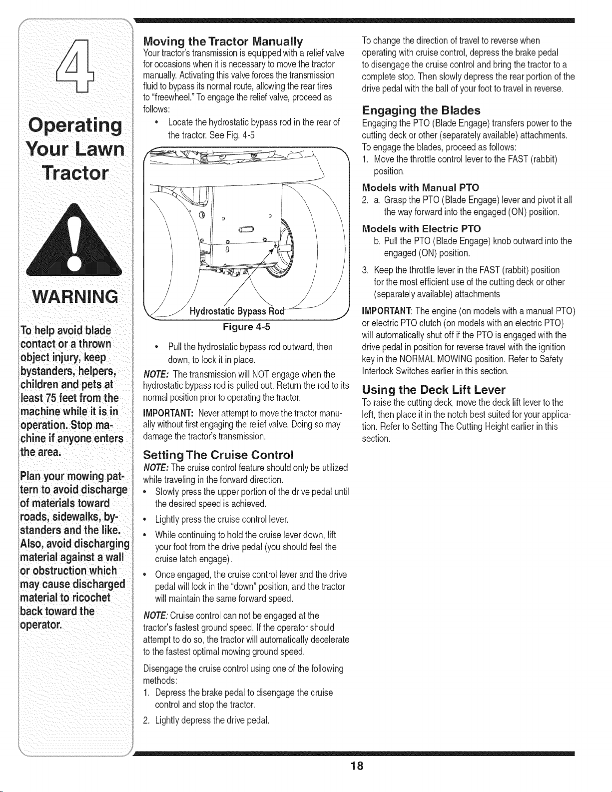
• Locatethe hydrostaticbypassrodin the rear of
the tractor.See Fig.4-5
Hydrostatic Bypass
Figure 4=5
Pullthe hydrostaticbypassrodoutward,then
down,to lockit in place.
NOTE: Thetransmissionwill NOTengagewhenthe
hydrostaticbypassrodis pulledout. Returnthe rodto its
normalpositionpriorto operatingthetractor.
IMPORTANT:Neverattemptto movethetractormanu-
allywithoutfirstengagingthe reliefvalve.Doingso may
damagethe tractor'stransmission.
Setting The Cruise Control
NOTE:The cruisecontrol featureshouldonly be utilized
whiletravelinginthe forwarddirection.
• Slowlypressthe upper portionof thedrive pedaluntil
thedesiredspeedis achieved.
• Lightlypress thecruisecontrollever.
• Whilecontinuingto hold the cruiseleverdown,lift
yourfootfrom the drivepedal(you shouldfeel the
cruiselatchengage).
• Onceengaged,the cruisecontrolleverandthe drive
pedalwill lock inthe "down"position,and the tractor
will maintainthe sameforwardspeed.
NOTE:Cruisecontrolcan notbe engagedat the
tractor'sfastestgroundspeed.If the operatorshould
attemptto doso, the tractorwill automaticallydecelerate
to the fastestoptimal mowinggroundspeed.
Disengagethecruisecontrolusingone of the following
methods:
1. Depressthe brakepedalto disengagethecruise
controlandstop the tractor.
2. Lightlydepressthe drivepedal.
Tochangethe directionof travelto reversewhen
operatingwith cruisecontrol,depressthe brakepedal
to disengagethe cruise controlandbring thetractorto a
completestop.Thenslowlydepressthe rearportionof the
drivepedalwiththe ballof yourfoot to travelin reverse.
Engaging the Blades
Engagingthe PTO(BladeEngage)transferspowerto the
cuttingdeckor other(separatelyavailable)attachments.
Toengagethe blades,proceedas follows:
1. Movethe throttlecontrolleverto the FAST(rabbit)
position.
Models with Manual PTO
2. a. Graspthe PTO(BladeEngage)leverand pivotit all
the wayforwardinto theengaged(ON) position.
Models with Electric PTO
b. Pullthe PTO(Blade Engage)knoboutwardintothe
engaged(ON)position.
3. Keepthe throttleleverin the FAST(rabbit)position
for the mostefficientuseof the cuttingdeck or other
(separatelyavailable)attachments
IMPORTANT:The engine(onmodelswith a manualPTO)
orelectric PTOclutch(on modelswith an electricPTO)
will automaticallyshutoff if the PTOis engagedwith the
drivepedalin positionfor reversetravelwith the ignition
keyin the NORMALMOWINGposition.Referto Safety
InterlockSwitchesearlierin thissection.
Using the Deck Lift Lever
Toraisethe cuttingdeck,movethe deck lift leverto the
left, thenplaceit inthe notch bestsuitedforyour applica-
tion.Referto SettingThe CuttingHeightearlierin this
section.
18
Mowing
,_ WARNING:Tohelp avoid blade contact or
a thrown object injury,keep bystanders,
helpers, children and pets at least 75feet
from the machine while it is in operation.
Stop machine if anyone enters the area.
Thefollowinginformationwill be helpfulwhenusingthe
cuttingdeckwith yourtractor:
WARNING:Plan your mowing pattern to
avoid discharge of materials toward roads,
sidewalks, bystanders and the like. Also,
avoid discharging material against a wall
or obstruction which may cause dis-
charged material to ricochet back toward
the operator.
• Do not mowat high groundspeed,especiallyif a
mulchkit orgrass collectoris installed.
• Forbest resultsit is recommendedthat the firsttwo
laps becut withthe dischargethrowntowardsthe
center.After thefirst two laps,reversethedirectionto
throwthe dischargeto the outsidefor the balanceof
cutting.Thiswill givea betterappearanceto the lawn.
• Do notcut the grasstoo short.Shortgrass invites
weedgrowthandyellowsquicklyin dryweather.
• Mowingshouldalwaysbe donewiththe engineat full
throttle.
Underheavierconditionsit may benecessaryto go
backoverthe cut areaa secondtimeto get a clean
cut.
Do NOTattemptto mowheavybrushand weedsand
extremelytall grass.Yourtractoris designedto mow
lawns,NOTclearbrush.
• Keepthe bladessharpand replacethe bladeswhen
worn.Referto Cutting Blades inthe Maintaining
Your LawnTractor sectionof thismanualfor proper
bladesharpeninginstructions.
Headlights
• The lampsare ONwheneverthe ignitionkey ismoved
outof the STOPposition.
• The lampsturnOFF whenthe ignitionkeyismovedto
the STOPposition.
\
Figure 4-6
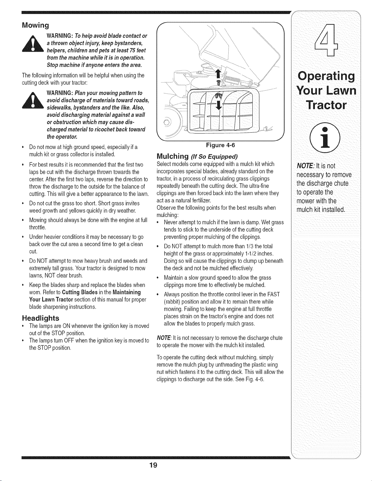
Mulching (If so Equipped)
Selectmodelscomeequippedwith a mulchkit which
incorporatesspecialblades,alreadystandardon the
tractor,ina processof recirculatinggrass clippings
repeatedlybeneaththe cuttingdeck.The ultra-fine
clippingsarethen forcedback intothe lawnwherethey
actas a naturalfertilizer.
Observethe followingpointsfor the best resultswhen
mulching:
• Neverattemptto mulchifthe lawnisdamp.Wetgrass
tendsto stickto the undersideof the cuttingdeck
preventingpropermulchingof the clippings.
• Do NOTattemptto mulchmorethan 1/3 thetotal
heightof the grass orapproximately1-1/2inches.
Doingsowill causethe clippingsto clump upbeneath
thedeckand not be mulchedeffectively.
• Maintaina slow groundspeedto allow the grass
clippingsmoretimeto effectivelybe mulched.
• Alwayspositionthethrottlecontrolleverin the FAST
(rabbit)positionandallow it to remainthere while
mowing.Failingto keepthe engineat full throttle
placesstrainon thetractor'sengineanddoes not
allowthe bladesto properlymulch grass.
NOTE:It is notnecessaryto removethe dischargechute
to operatethe mowerwith the mulch kitinstalled.
Tooperatethe cuttingdeck withoutmulching,simply
removethe mulchplugby unthreadingthe plasticwing
nutwhichfastensit to the cuttingdeck.This will allowthe
clippingsto dischargeoutthe side.See Fig.4-6.
19
Operati
NOTE: It is not
necessary to remove
the discharge chute
to operatethe
mowerwith the
mulch kit installed.
WARNING
Never attemptto make
any adjustments
whilethe engine
is running, except
where specified inthe
operator'smanuaJ.
Never attempt to
adjust the brakes
while the engine
is running. Always
disengage PTO, move
shift lever into neutral
i position, stop engine
and remove key to
prevent unintended
starting.
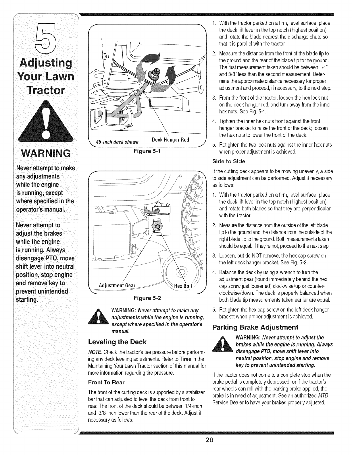
46-inch deckshown Deck
Figure 5=1
Withthe tractorparkedona firm,levelsurface,place
the decklift leverin the top notch(highestposition)
androtatethe blade nearestthe dischargechute so
thatitis parallelwith the tractor.
Measurethe distancefromthe frontof thebladetip to
thegroundandthe rearof thebladetip tothe ground.
Thefirstmeasurementtakenshouldbe between1/4"
and3/8" lessthanthe secondmeasurement.Deter-
minethe approximatedistancenecessaryfor proper
adjustmentandproceed,if necessary,to thenext step.
Fromthe frontof thetractor,loosenthe hexlock nut
onthe deck hangerrod,andturn awayfromthe inner
hexnuts. SeeFig.5-1.
Tightenthe innerhex nutsfront againstthe front
hangerbracketto raisethe frontof the deck;loosen
the hexnutsto lowerthe frontof the deck.
Retightenthe two locknutsagainstthe innerhexnuts
whenproperadjustmentis achieved.
Side to Side
If the cuttingdeck appearsto be mowingunevenly,a side
to side adjustmentcan be performed.Adjustif necessary
as follows:
.
Withthe tractorparkedona firm,levelsurface,place
the decklift leverin the top notch(highestposition)
androtateboth bladesso thatthey areperpendicular
withthe tractor.
Figure 5=2
,_ WARNING:Never attempt to makeany
adjustments while the engine is running,
except where specified in the operator's
manual.
Leveling the Deck
NOTE:Checkthe tractor'stire pressurebeforeperform-
inganydeck levelingadjustments.Referto Tires in the
MaintainingYour LawnTractorsectionof this manualfor
moreinformationregardingtire pressure.
Front To Rear
Thefrontof the cuttingdeck issupportedbya stabilizer
barthat canadjustedto levelthe deck fromfrontto
rear.The front of the deck shouldbe between1/4-inch
and 3/8-inch lowerthanthe rear of the deck.Adjust if
necessaryas follows:
2. Measurethedistancefromtheoutsideof theIdt blade
tipto thegroundandthe distancefromtheoutsideof the
rightbladetip totheground.Bothmeasurementstaken
shouldbeequal.Ifthey'renot,proceedto thenextstep.
3. Loosen,butdo NOTremove,the hexcap screwon
the leftdeck hangerbracket.SeeFig.5-2.
.
Balancethe deck by usinga wrenchto turn the
adjustmentgear(foundimmediatelybehindthe hex
cap screwjust loosened)clockwise/upor counter-
clockwise/down.Thedeck is properlybalancedwhen
bothbladetip measurementstakenearlierare equal.
5. Retightenthe hex capscrewon the left deckhanger
bracketwhenproperadjustmentis achieved.
Parking Brake Adjustment
_ ARNING:Neverattempt to adjust the
brakes while the engine is running. Always
disengage PTO,moveshift lever into
neutral position, stop engineand remove
key to prevent unintended starting.
If the tractordoes notcome to a completestopwhenthe
brakepedalis completelydepressed,or if the tractor's
rearwheelscan roll withthe parkingbrakeapplied,the
brakeis in needof adjustment.Seean authorizedMTD
ServiceDealerto haveyourbrakesproperlyadjusted.
2O
Seat
Adjustment
f
Quick Adjust Seat (Ifso equipped)
WARNING:Before operating this machine,
make sure the seat is engaged in the seat
stop, stand behind the machine and pull
back on seat until fully engaged into stop.
Toadjustthe positionof the seaton modelsequipped
witha seat adjustmentlever,movethe leverto the left
and slidethe seatforwardor rearward.Referto the
SettingUpYour LawnTractorsection.Makesure seat
is lockedintopositionbeforeoperatingthe tractor.
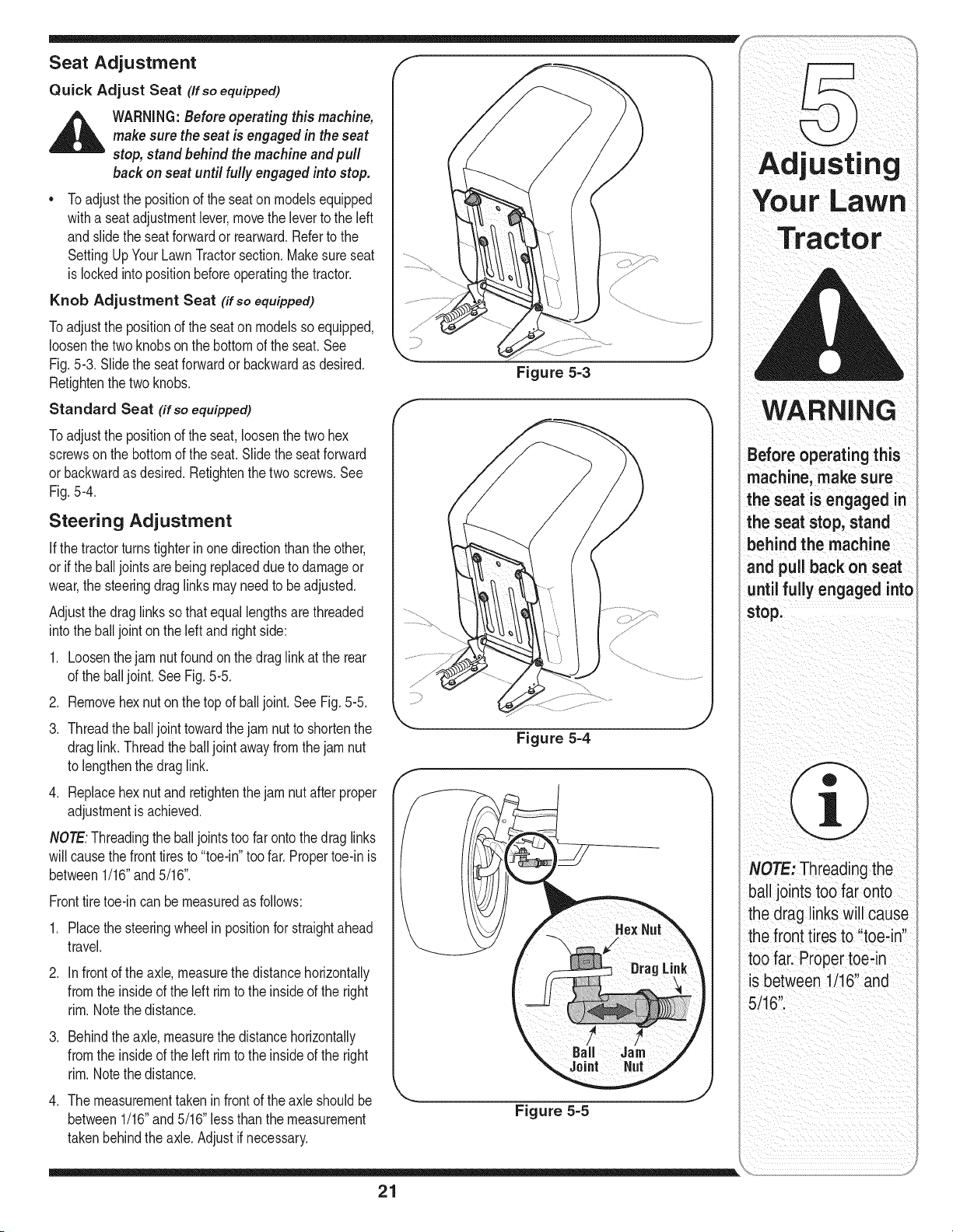
Knob Adjustment Seat (if so equipped)
Toadjustthe positionof the seaton modelsso equipped,
loosenthe twoknobson the bottomof theseat. See
Fig.5-3. Slidethe seatforwardor backwardas desired.
Retightenthe two knobs.
Standard Seat (if so equipped)
Toadjustthe positionof the seat,loosenthe twohex
screwson the bottomof the seat.Slide the seatforward
or backwardas desired.Retightenthe two screws.See
Fig.5-4.
Steering Adjustment
Ifthe tractorturnstighter inone directionthanthe other,
or if the balljoints arebeing replaceddue to damageor
wear,the steeringdraglinksmay needto beadjusted.
Adjustthe draglinks so that equallengthsare threaded
into the balljoint on the leftand rightside:
1. Loosenthejam nut foundon the drag linkat the rear
of the balljoint. See Fig.5-5.
2. Removehex nuton thetop of balljoint. See Fig.5-5.
3. Threadthe balljoint towardthejam nut to shortenthe
draglink. Threadtheballjoint awayfrom thejam nut
to lengthenthe drag link.
4. Replacehex nutand retightenthejam nut afterproper
adjustmentis achieved.
NOTE:Threadingthe balljoints too far ontothe drag links
will causethe fronttires to "toe-in"too far. Propertoe-in is
between1/16"and 5/16".
Fronttiretoe-in canbe measuredas follows:
1. Placethe steeringwheelin positionfor straightahead
travel.
2. Infrontof the axle, measurethe distancehorizontally
fromthe insideof the left rimto the insideof the right
rim.Notethe distance.
3. Behindthe axle,measurethe distancehorizontally
fromthe insideof the left rimto the insideof the right
rim.Notethe distance.
4. The measurementtakenin frontof the axle shouldbe
between1/16"and 5/16"less thanthe measurement
takenbehindthe axle.Adjust if necessary.
Figure 5-3
Figure 5-4
Figure 5-5
Adjusting
Before operating this
machine, make sure
the seat is engaged in
the seat stop; stand
behind the machine
and pull back on seat
stop:
NOTE: Threadingthe
ball joints too far onto
the drag linkSWill Cause
the front tires to 'ttoeqn'!
tOOfarl Proper t!eqn
is bt!ween i/i6 and
5ii61
21
WARNING
Before performing
anymaintenanceor
repairs,disengage
PTO, move shift lever
intoneutral position,
set parking brake,
stop engine and
remove key to prevent
unintendedstarting.
Before lubricating,
repairing, or inspect-
ing, always disengage
PTO, move shift lever
into neutral position,
set parking brake,
stop engine and
remove key to prevent
unintendedstarting.
Shown
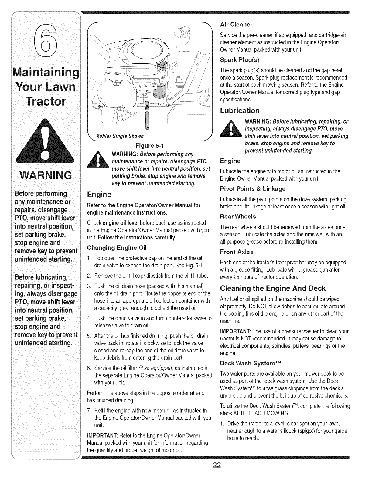
Figure 6-1
_ ARNING:Before performing any
maintenanceor repairs,disengagePTO,
moveshift lever into neutral position, set
parking brake,stop engine and remove
key to prevent unintended starting.
Engine
Referto the Engine Operator/Owner Manualfor
engine maintenance instructions.
Checkengine oil level beforeeachuseas instructed
inthe EngineOperator/OwnerManualpackedwith your
unit.Follow the instructionscarefully.
Changing Engine Oil
.
3.
.
Popopenthe protectivecap on the end of the oil
drainvalveto exposethedrain port.See Fig.6-1.
Removethe oil fill cap/dipstick fromthe oil fill tube.
Pushthe oildrain hose(packedwiththis manual)
ontothe oil drainport. Routethe oppositeendof the
hoseinto anappropriateoil collectioncontainerwith
a capacitygreatenoughtocollect theusedoil.
Pushthe drainvalvein andturn counter-clockwiseto
releasevalveto drainoil.
.
.
Afterthe oil has finisheddraining,pushtheoil drain
valvebackin, rotateit clockwiseto lock the valve
closedand re-capthe end of the oil drainvalveto
keepdebrisfromenteringthedrainport.
Servicethe oilfilter (if so equipped)as instructedin
the separateEngineOperator/OwnerManualpacked
withyourunit.
Performthe abovestepsinthe oppositeorderafter oil
hasfinisheddraining.
7. Refillthe enginewith newmotoroilas instructedin
the EngineOperator/OwnerManualpackedwith your
unit.
IMPORTANT:Referto the EngineOperator/Owner
Manualpackedwith yourunit for informationregarding
thequantityandproperweightof motoroil.
Air Cleaner
Servicethe pre-cieaner,if soequipped,andcartridge/air
cleanerelementas instructedin the EngineOperator/
OwnerManualpackedwith your unit.
Spark Plug(s)
Thesparkplug(s)shouldbe cleanedand thegap reset
oncea season.Sparkplug replacementis recommended
at the startof each mowingseason.Referto the Engine
Operator/OwnerManualfor correctplug typeand gap
specifications.
Lubrication
_ ARNING:Before lubricating, repairing, or
inspecting, always disengage PTO,move
shift lever into neutral position, set parking
brake, stop engine and remove key to
prevent unintended starting.
Engine
Lubricatethe enginewithmotoroil as instructedin the
EngineOwnerManualpackedwith yourunit.
Pivot Points & Linkage
Lubricateall the pivotpointson the drivesystem,parking
brakeand lift linkageat leastoncea seasonwithlightoil.
Rear Wheels
The rearwheelsshouldbe removedfrom the axlesonce
a season.Lubricatethe axles andthe rimswell with an
all-purposegreasebeforere-installingthem.
Front Axles
Eachendof the tractor'sfront pivotbarmay beequipped
witha greasefitting. Lubricatewitha greasegunafter
every25 hoursof tractoroperation.
Cleaning the Engine And Deck
Anyfuel oroil spilledon the machineshouldbe wiped
off promptly.Do NOTallowdebristo accumulatearound
the coolingfins of the engineor onany otherpart of the
machine.
IMPORTANT:The useof a pressurewasherto cleanyour
tractoris NOTrecommended,it maycause damageto
electricalcomponents,spindles,pulleys,bearingsor the
engine.
Deck Wash System TM
Twowaterportsare availableon your mowerdeck to be
usedas part of the deckwashsystem.Usethe Deck
WashSystemTM to rinsegrassclippingsfrom the deck's
undersideand preventthe buildupof corrosivechemicals.
Toutilizethe DeckWash SystemTM, completethefollowing
stepsAFTEREACHMOWING:
1. Drivethe tractorto a level,clearspoton yourlawn,
nearenoughto awater sillcock(spigot)for yourgarden
hoseto reach.
22
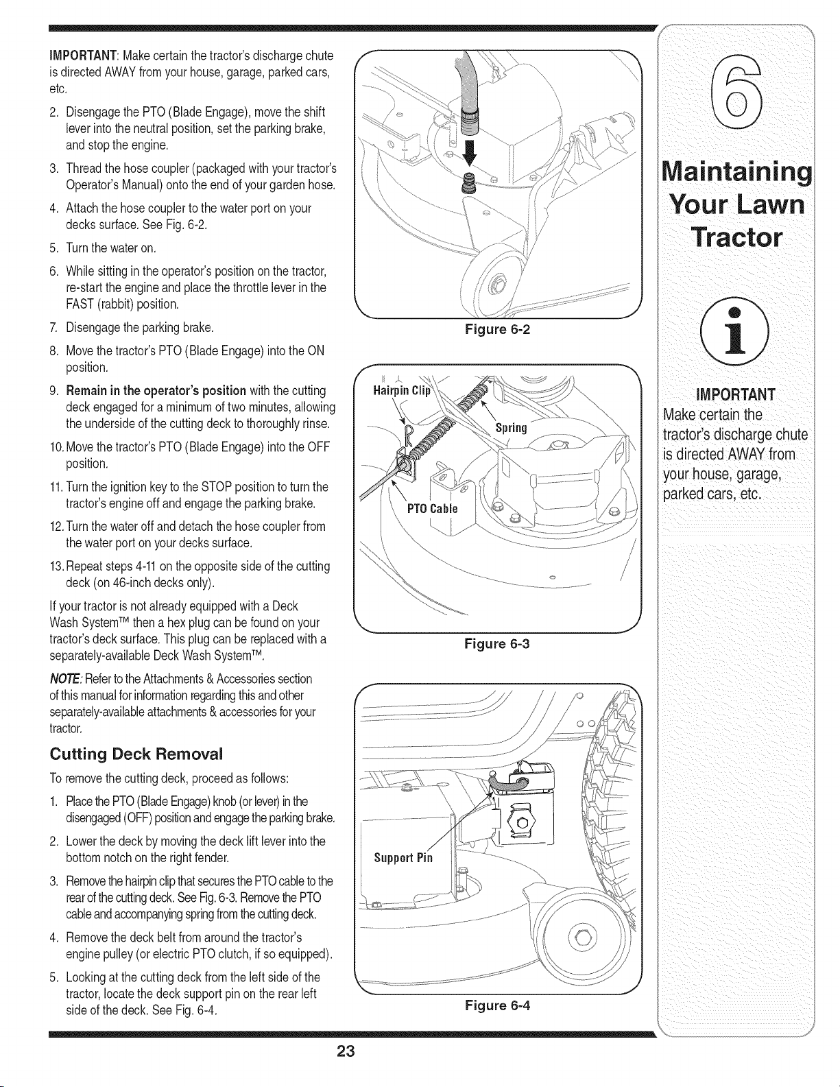
iMPORTANT:Makecertainthetractor'sdischargechute
is directedAWAYfromyourhouse,garage,parkedcars,
etc.
,
,
,
Disengagethe PTO(BladeEngage),movethe shift
leverintothe neutralposition,set the parkingbrake,
andstop the engine.
Threadthe hosecoupler(packagedwith yourtractor's
Operator'sManual)ontothe end of yourgardenhose.
Attachthe hosecouplerto the waterport on your
deckssurface,SeeFig, 6-2,
5. Turnthe wateron.
,
,
8.
,
Whilesittingin theoperator'spositiononthe tractor,
re-starttheengineand placethethrottle leverin the
FAST(rabbit)position.
Disengagethe parkingbrake.
Movethe tractor'sPTO(BladeEngage)intothe ON
position.
Remainin the operator's positionwith thecutting
deckengagedfor a minimumof two minutes,allowing
the undersideof the cuttingdeck to thoroughlyrinse.
10.Movethe tractor'sPTO(BladeEngage)intothe OFF
position.
11.Turnthe ignitionkey to the STOPpositionto turn the
tractor'sengineoff andengagethe parkingbrake.
12.Turnthe wateroff and detachthe hosecouplerfrom
thewaterport on yourdeckssurface.
13.Repeatsteps4-11on theoppositesideof the cutting
deck(on 46-inchdecksonly).
If yourtractoris notalreadyequippedwitha Deck
WashSystemTM then a hexplug can be foundonyour
tractor'sdecksurface.This plugcan bereplacedwith a
separately-availableDeckWash SystemTM.
NOTE:RefertotheAttachments&Accessoriessection
ofthismanualfor informationregardingthisandother
separately-availableattachments& accessoriesforyour
tractor.
Figure 6=2
Figure 6-3
Cutting Deck Removal
To removethecuttingdeck, proceedas follows:
1. PlacethePTO(BladeEngage)knob(orlever)inthe
disengaged(OFF)positionandengagetheparkingbrake.
2. Lowerthe deck by movingthedeck liftleverintothe
bottomnotchonthe rightfender.
3. Removethehairpinclipthatsecuresthe PTOcabletothe
rearofthecuttingdeck.SeeFig.6-3.RemovethePTO
cableandaccompanyingspringfromthecuttingdeck.
4. Removethe deck belt fromaroundthe tractor's
enginepulley(orelectricPTOclutch, if so equipped).
5. Lookingat the cuttingdeck fromtheleft sideof the
tractor,locatethe decksupportpin onthe rearleft
sideof the deck. SeeFig. 6-4.
Figure 6-4
23
IMPORTANT
Make certain the
tractor's discharge chute
is directed AWAYfrom
your house, garage,
parked cars. etc.
6. Pullthe decksupport pinoutwardto releasethe deck Charging
fromthedeck lift arm.
WARNING
Never exceed the
maximum inflation
pressure shown on
the sidewall of the
tire.
Batteries give off an
explosive gas while
charging. Charge
battery in a well
ventilated area and
keep away from an
open flame or pilot
light as on a water
heater, space heater,
furnace, clothes
dryer or other gas
appliances.
When removing or
installingthe battery,
follow these instruc-
tions to preventthe
screwdriver from
shorting against the
frame.
.
.
9.
Rotatethe pin slightlytowardthe rear of the tractor
andreleasethe pin intothe holeprovided.
Repeatthe abovestepson the tractor'srightside.
Movethe decklift leverintothe top notchon the right
fenderto raisedeck liftarms upand out of the way.
10.Gentlyslidethe cuttingdeck towardthe frontof the
tractorallowingthe hookson the deck to release
themselvesfromthe deck stabilizerrod.
11.Gentlyslidethe cuttingdeck (fromthe rightside)out
fromunderneaththetractor.
Tires
,_ WARNING:Never exceed the maximum
inflation pressure shown on the sidewall
of tire.
The recommendedoperatingtire pressureis:
• Approximately10psifor the rear tires
IMPORTANT:Whenchargingyourtractor'sbattery,use
onlya chargerdesignedfor 12Vlead-acidbatteries.Read
yourbatterycharger'sOwner'sManualpriorto charging
yourtractor'sbattery.Alwaysfollow itsinstructionsand
heedits warnings.
If yourtractorhasnot beenputinto usefor an extended
periodof time,chargethe batteryas follows:
• Setyour batterychargerto delivera maximumof 10
amperes.If your batterychargerisautomatic,charge
the batteryuntilthe chargerindicatesthat chargingis
complete.
NOTE:Ifthe chargerisnotautomatic,chargefor no fewer
thaneight hours.
_hl ARNING:Batteries give off an explosive
gas while charging. Charge battery in a
well ventilated areaand keep away from
an open flame or pilot light as on a water
heater,space heater, furnace, clothes dryer
or other gas appliances.
• Approximately14psi for the fronttires
IMPORTANT:Referto the tire sidewallforexacttire
manufacturer'srecommendedormaximumpsi. Do not
overinflate.Uneventirepressurecouldcausethe cutting
deckto mow unevenly.
Jump Starting
_i/|ll ARNING:Whenremoving or installing the
battery, follow these instructions to prevent
the screwdriver from shorting against the
frame.
Battery
The batteryis sealedand is maintenance-free.Acid
levelscannotbechecked.
Alwayskeepthe batterycablesand terminalsclean
andfreeof corrosivebuild-up.
• Aftercleaningthe batteryandterminals,apply a light
coatof petroleumjelly or greaseto bothterminals.
• Alwayskeepthe rubberboot positionedoverthe
positiveterminalto preventshorting.
IMPORTANT:Ifremovingthe batteryfor anyreason,
disconnectthe NEGATIVE(Black)wire fromit'sterminal
first,followedby the POSITIVE(Red)wire. When
re-installingthe battery,alwaysconnectthe POSITIVE
(Red)wire itsterminalfirst, followedby the NEGATIVE
(Black)wire.Be certainthat thewiresareconnectedto
thecorrectterminals;reversingthemcouldchangethe
polarityandresult indamageto your engine'salternat-
ingsystem.
IMPORTANT:Neverjumpyourtractor'sdeadbatterywith
the batteryof a runningvehicle.
1. Connectend of one jumpercableto the positive
terminalof the goodbattery,thenthe otherend to the
positiveterminalof the dead battery.
2. Connectthe otherjumpercable to the negative
terminalof the goodbattery,thento the frame of the
unit with the dead battery.
_ WARNING:Failure to use this procedure
could cause sparking, and thegas in either
battery could explode.
Cleaning
Cleanthe batteryby removingit fromthe tractorand
washingwitha bakingsodaand watersolution.If neces-
sary,scrapethe batteryterminalswith a wire brushto
removedeposits.Coatterminalsand exposedwiringwith
greaseor petroleumjelly to preventcorrosion.
Battery Failures
Somecommoncausesfor batteryfailureare:
incorrectinitialactivation • undercharging
• overcharging
• freezing
• corrodedconnections
NOTE:ThesefailuresareNOTcoveredbyyour tractor's
warranty.
24
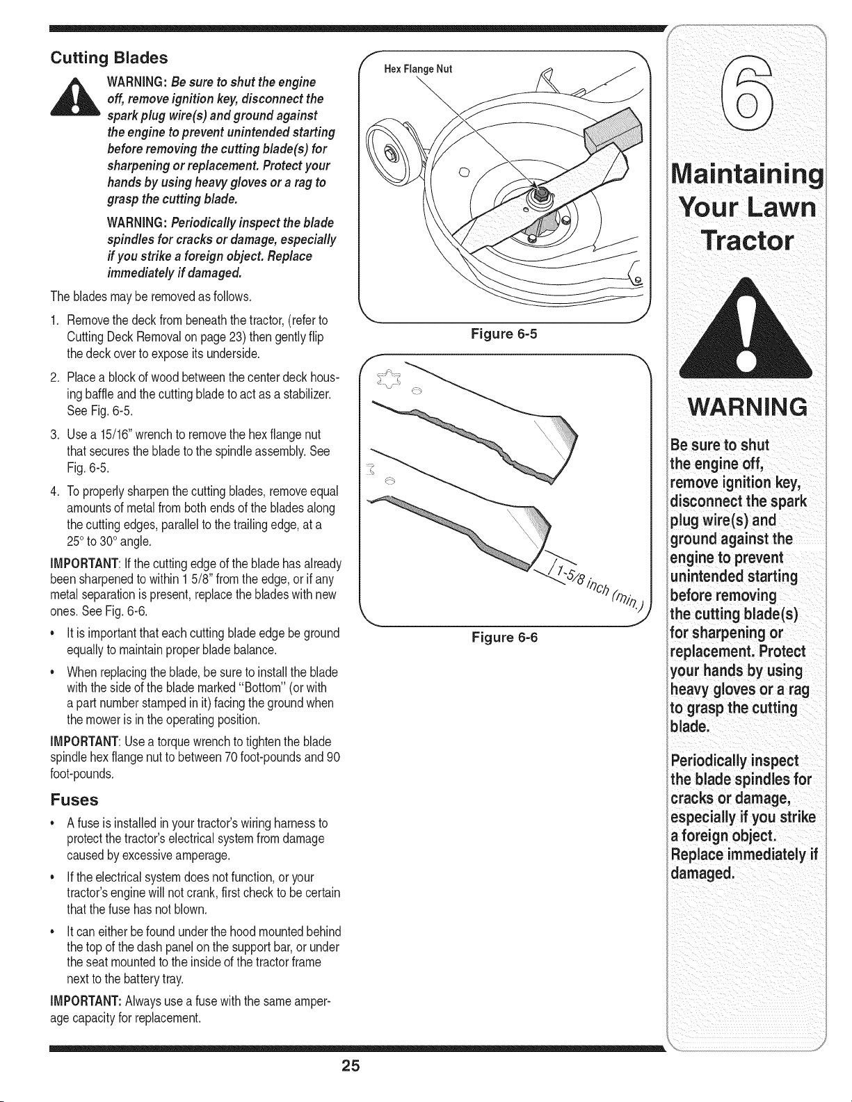
Cutting Blades
_ ARNING: Besure to shut the engine
off, remove ignition key,disconnect the
spark plug wire(s) and ground against
the engine to prevent unintended starting
before removing the cutting blade(s) for
sharpening or replacement. Protect your
hands by using heavy gloves or a rag to
grasp the cutting blade.
WARNING: Periodically inspect the blade
spindles for cracks or damage, especially
if you strike a foreign object. Replace
immediately if damaged.
The bladesmay beremovedas follows.
1. Removethe deck frombeneaththe tractor,(referto
CuttingDeckRemovalon page23) thengentlyflip
thedeckoverto expose itsunderside.
2. Placea blockof wood betweenthe centerdeckhous-
ingbaffle andthe cuttingbladeto act as a stabilizer.
SeeFig. 6-5.
3. Usea 15/16"wrenchto removethe hexflangenut
thatsecuresthe bladeto the spindleassembly.See
Fig.6-5.
4. Toproperlysharpenthe cuttingblades,removeequal
amountsof metalfrom bothends of the bladesalong
thecutting edges,parallelto the trailingedge,at a
250to 300angle.
IMPORTANT:Ifthe cuttingedgeof the bladehasalready
beensharpenedto within15/8" fromtheedge,or if any
metalseparationis present,replacethe bladeswith new
ones.See Fig.6-6.
• It is importantthat eachcuttingbladeedgebe ground
equallyto maintainproperblade balance.
• Whenreplacingtheblade,be sureto installthe blade
withthe sideof the blade marked"Bottom" (orwith
a part numberstampedin it) facingthe groundwhen
the moweris inthe operatingposition.
IMPORTANT:Usea torquewrenchto tighten the blade
spindlehexflangenutto between70foot-poundsand90
foot-pounds.
Fuses
Afuse is installedin yourtractor'swiringharnessto
protectthe tractor'selectricalsystemfromdamage
causedby excessiveamperage.
If theelectricalsystemdoesnot function,or your
tractor'senginewill not crank,firstcheckto be certain
thatthe fuse hasnot blown.
• It caneither be foundunderthe hood mountedbehind
thetop of the dash panelon the supportbar,or under
the seatmountedto the insideof the tractorframe
nextto the batterytray.
IMPORTANT:Alwaysusea fuse withthe sameamper-
agecapacityfor replacement.
He× Flange Nut
Figure 6=5
\
Figure 6=6
Maintaining
WARNING
Be sure to shut
the engine off,
remove ignition key,
disconnect the spark
plug wire(s) and
ground against the
engine to prevent
unintended starting
before removing
the cutting blade(s)
for sharpening or
replacement. Protect
your hands by using
heavy gloves or a rag
to grasp the cutting
blade.
Periodically inspect
the blade spindles for
cracks or damage,
especially if you strike
a foreign object.
Replace immediately if
damaged.
25
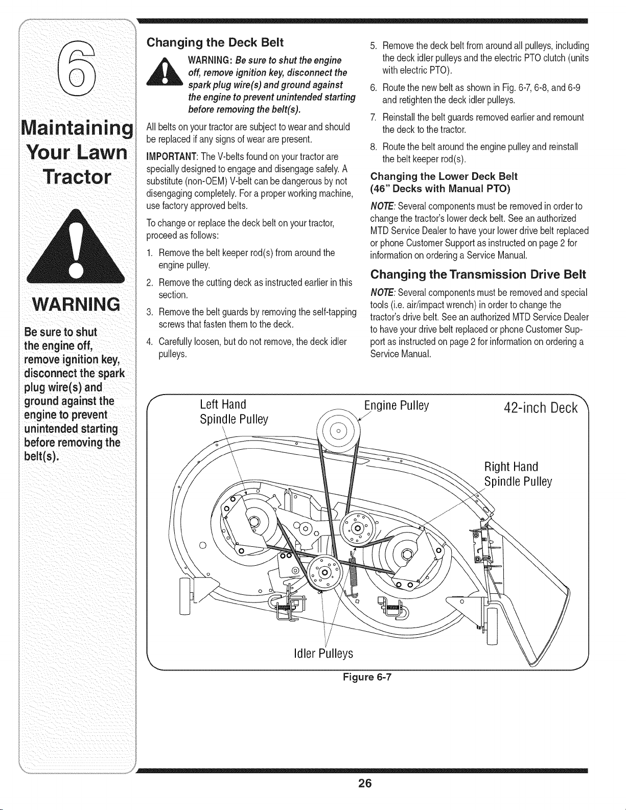
Maintaining
WARNING
Be sure to shut
the engine off,
remove ignition key,
disconnect the spark
plugwire(s) and
ground againstthe
engine to prevent
unintendedstarting
before removingthe
belt(s).
Changing the Deck Belt
,_ WARNING:Besure to shut the engine
off, removeignition key,disconnectthe
sparkplug wire(s) and groundagainst
the engineto prevent unintendedstarting
beforeremoving the belt(s).
All beltson yourtractorare subjectto wearand should
be replacedifanysigns of weararepresent.
iMPORTANT:TheV-beltsfoundon yourtractorare
speciallydesignedto engageanddisengagesafely.A
substitute(non-OEM)V-beltcan be dangerousby not
disengagingcompletely.Fora properworkingmachine,
usefactoryapprovedbelts.
Tochangeor replacethe deck belt on yourtractor,
proceedas follows:
1. Removethe beltkeeperrod(s)fromaroundthe
enginepulley.
2. Removethe cuttingdeck as instructedearlierin this
section.
3. Removethe beltguardsby removingthe self-tapping
screwsthatfastenthemto the deck.
4. Carefullyloosen,butdo not remove,the deck idler
pulleys.
,
,
,
Removethedeck belt fromaroundall pulleys,including
the deckidler pulleysandthe electricPTOclutch(units
withelectricPTO).
Routethe newbelt as shownin Fig.6-7,6-8, and6-9
andretightenthe deck idlerpulleys.
Reinstallthe beltguardsremovedearlierand remount
the deckto thetractor.
8. Routethe beltaroundtheengine pulleyand reinstall
the beltkeeperrod(s).
Changing the Lower Deck Belt
(46" Decks with Manual PTO)
NOTE:Severalcomponentsmustbe removedin orderto
changethe tractor'slowerdeck belt. Seean authorized
MTDServiceDealerto haveyourlowerdrivebelt replaced
or phoneCustomerSupportas instructedon page2 for
informationonorderinga ServiceManual.
Changing the Transmission Drive Belt
NOTE:Severalcomponentsmustbe removedand special
tools(i.e.air/impactwrench)in orderto changethe
tractor'sdrive belt.Seean authorizedMTDServiceDealer
to haveyourdrivebelt replacedor phoneCustomerSup-
portas instructedonpage 2 for informationonorderinga
ServiceManual.
Left Hand
Spindle Pulley
ine Pulley
42-inch Deck
Right Hand
Spindle Pulley
0
Idler Pulleys
Figure 6=7
26
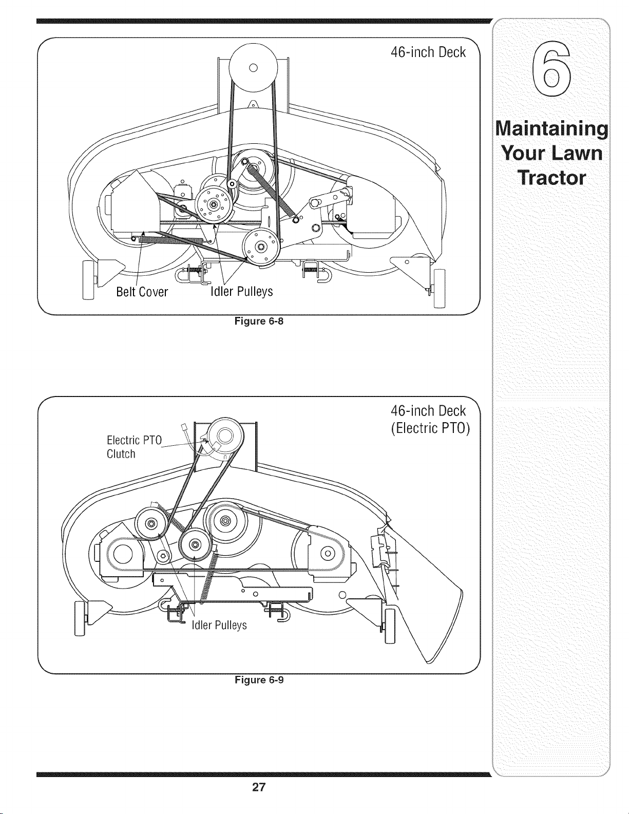
46-inch Deck
0
Belt Cover
Idler Pulleys
Figure 6=8
Electric PTO
Clutch
46-inch Deck
(Electric PTO)
o o
Figure 6=9
Maintaining
Your Lawn
Tractor
27
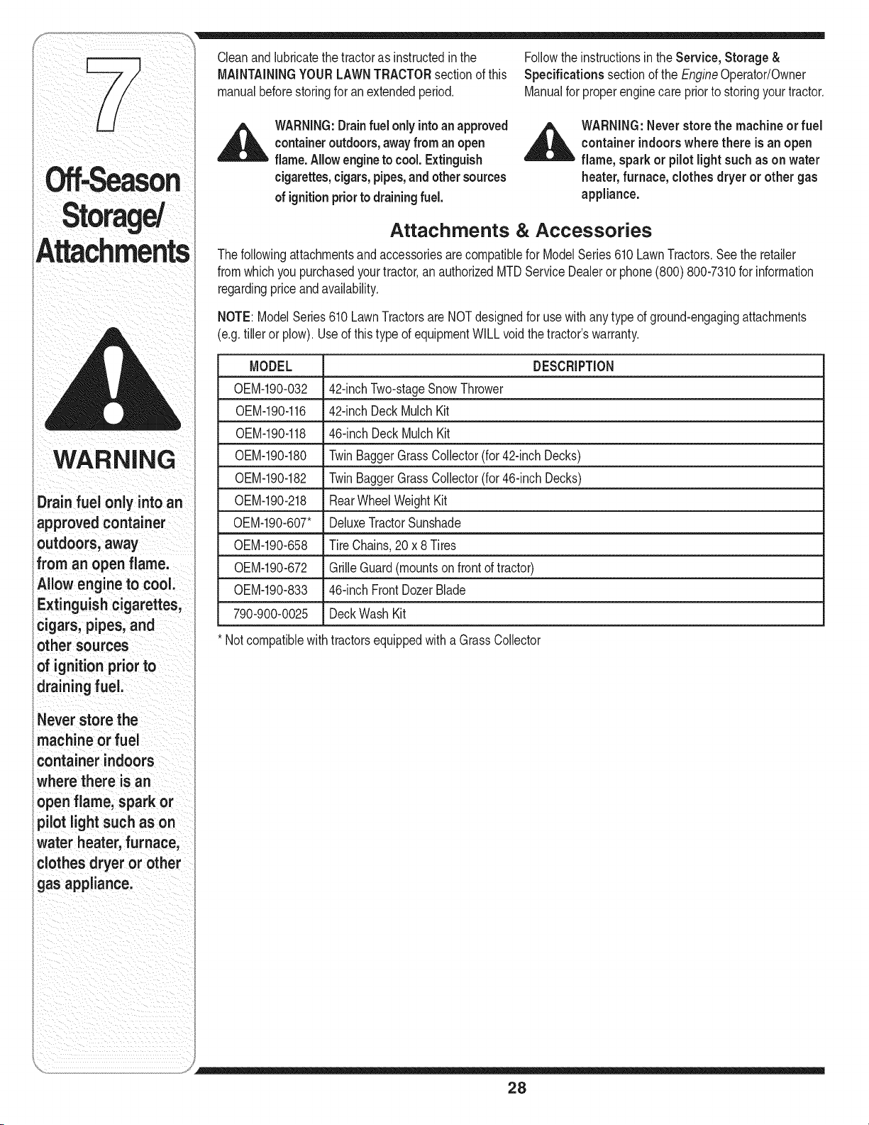
WARNING
i Drain fuel only into an
approvedcontainer
outdoors,away
ifrom anopenflame.
i Allowengineto cool.
i Extinguishcigarettes,
'cigars, pipes, and
other sources
of ignition prior to
, draining fuel.
i Never store the
i machine or fuel
container indoors
_where there is an
open flame, spark or
i pilot light such as on
water heater, furnace,
clothes dryer or other
gas appliance.
Cleanandlubricatethe tractoras instructedin the Followthe instructionsin the Service, Storage &
MAiNTAiNiNGYOUR LAWNTRACTORsectionof this Specifications sectionof the EngineOperator/Owner
manualbeforestoringfor an extendedperiod. Manualfor properenginecare priorto storingyourtractor.
_i= ARNING:Drainfuel only intoan approved
containeroutdoors,awayfrom anopen
flame.Allowengineto cool. Extinguish
cigarettes,cigars, pipes,andothersources
of ignitionpriorto drainingfuel.
,A_ WARNING:Neverstore the machineor fuel
container indoorswhere there is an open
flame, spark or pilotlightsuch as on water
heater,furnace, clothes dryer or othergas
appliance.
Attachments & Accessories
Thefollowingattachmentsand accessoriesarecompatiblefor ModelSeries610 LawnTractors.Seethe retailer
fromwhichyou purchasedyourtractor,an authorizedMTDServiceDealeror phone(800) 800-7310for information
regardingpriceandavailability.
NOTE:ModelSeries610 LawnTractorsareNOTdesignedfor use withanytype of ground-engagingattachments
(e.g.tiller or plow).Useof this typeof equipmentWILLvoidthe tractor'swarranty.
MODEL DESCRiPTiON
OEM-190-032 42-inchTwo-stageSnowThrower
OEM-190-116 42-inchDeckMulch Kit
0EM-190-118 46-inch DeckMulchKit
0EM-190-180 TwinBaggerGrassCollector(for 42-inchDecks)
0EM-190-182 TwinBaggerGrassCollector(for 46-inchDecks)
0EM-190-218 RearWheelWeightKit
0EM-190-607" DeluxeTractorSunshade
0EM-190-658 Tire Chains,20 x 8 Tires
0EM-190-672 GrilleGuard(mountsonfrontof tractor)
0EM-190-833 46-inch FrontDozerBlade
790-900-0025 DeckWashKit
* Notcompatiblewith tractorsequippedwitha Grass Collector
28
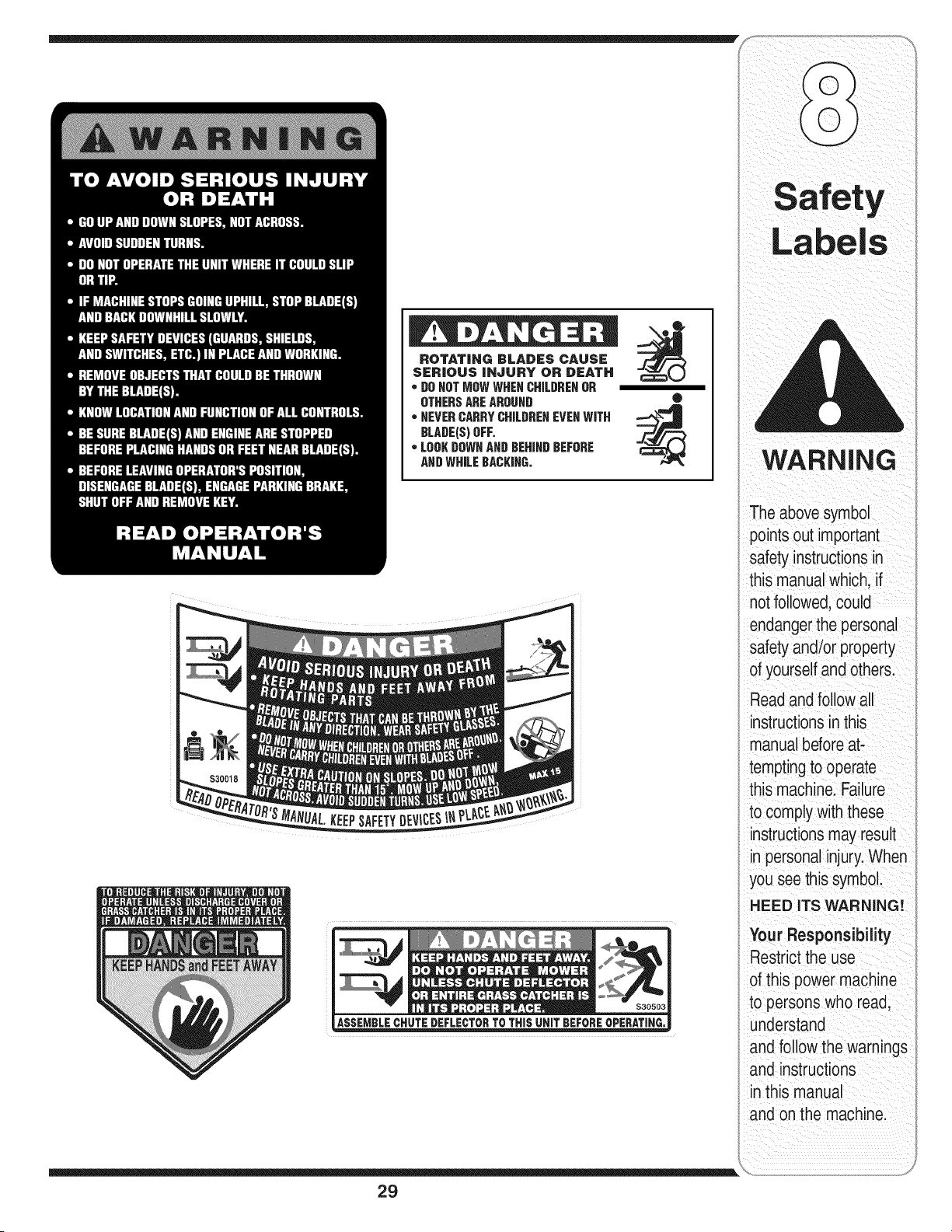
ROTATING BLADES CAUSE
SERIOUS INJURY OR DEATH
* DONOTMOWWHENCHILDRENOR
OTHERSAREAROUND
* NEVERCARRYCHILDRENEVENWiTH
BLADE(S)OFF,
* LOOKDOWNANDBEHINDBEFORE
ANDWHILEBACKING,
0
29
Labels
WARNING
The abovesymbol
points out important
safety instructionsin
this manual which, if
notfollowed,could
endangerthe personal
safety and/or property
of yourselfand others.
Readand follow all
instructionsinthis
manual beforeat-
temptingto operate
this machine. Failure
to comply with these
instructionsmay result
in personalinjury.When
you see this symbol.
HEED ITS WARNING!
Your Responsibility
Restrictthe use
of this power machine
to persons who read,
understand
and follow the warnings
and instructions
in this manual
and onthe machine.

For repairs beyond
the minor adjust-
ments listed here,
contact an authorized
service dealer.
Pro bl e m Ca use Remedy
Enginefails to start 1. PTOengaged• 1. PlacePTOknobindisengaged
(OFF)position•
2. Sparkplugwire(s)disconnected. 2. Connectwire(s) to spark plug(s)•
3 Fueltank em t or stalefuel 3 F tankwthc ean freshgaso ne
• py • •
4 Chokenot act vated 4. Pullout the CHOKEcontrol(if so
• equipped)orplacethe throttle
controlin CHOKEposition•
5. Faultysparkplug• 5. Clean,adjustgap,or replace•
6. Blockedfuel line• 6. Cleanfuel line or replacefuelfilter,
7. Engineflooded, if so equipped.
7. Crankenginewith throttle in FAST
position.
8. Parkingbrakenotengaged. 8. Engageparkingbrake.
' 9. Throttlecontrol levernotin correct 9. Placethrottleleverto FAST
- startingposition. . position.
Engineruns erratic 1. Unit runningwithCHOKEapplied. 1. PushCHOKEcontrolin.
2. Sparkplugwire(s) loose.
3. Blockedfuellineor stale fuel.
4. Ventingas cap plugged.
5. Waterordirt in fuel system.
6. Dirty aircleaner.
_ J _ =_
3O
2. Connectandtighten spark
plugwire(s).
3. Cleanfuel line;fill tank with clean,
fresh(less than30 daysold)
gasoline.Replacefuel filter,if so
equipped.
4. Clearvent or replaceif damaged.
5. Drainfuel tank. Refillwith
freshfuel.
6. Replaceaircleanercartridge/ele-
mentor cleanpre-cleaner,if so
equipped.
_ i
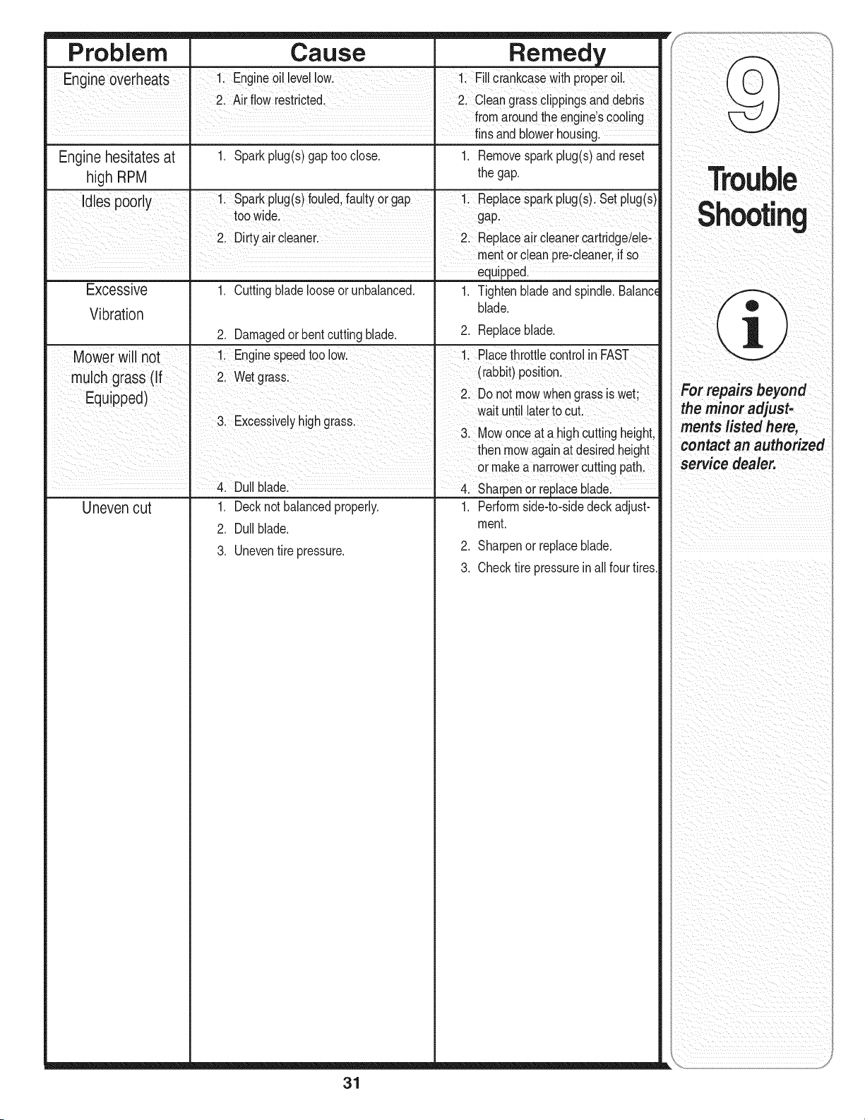
Problem Cause Remedy
Engine overheats 1! Engine0il level!0wl i: FillCrankcasewith pi0peroi!,
2. Air flowrestricted. Clean grassClippingsand debis
fromaroundthe engne Scoo!ing
....... finsand blowerhousing.
Enginehesitates at 1. Sparkplug(s)gap tooclose. 1. Removesparkplug(s)and reset
high RPM the gap.
desp0or 1 Sparkpug(s)foued fautyorgap 1 Repacesparkpug(s) Setpug(s)
Y '
too wide. gap.
2 Dirtyair Cleaner. 2 Replaceaircleaner cartridgeielei
....... equipped.
Excessive 1. Cuttingblade looseorunbalanced. 1. Tightenbladeandspindle. Balanc_
blade.
Vibration
2. Damagedorbentcuttingblade. 2. Replaceblade.
Mower will not li EngineSpeedtoo low, 1: Placethrottle controlin FAST
mulch grasS(f Wetgra_ (rabbit)position:
E J 2 Do not mowwhengrass swet;
qu pped) .... •
wat unt aterto cut
3. Excessivey hgh grass:
3. Mowonce at a highcuttingheight,
then mowagainat desiredheight
or makea narrowerCuttingpathl
Duilblade 4. sharpenOrreplaceblade:
Uneven cut 1. Decknotbalancedproperly. 1. Performside4o-sidedeck adjust-
2. Dullblade, mont.
2. Sharpenor replaceblade.
3. Uneventire pressure.
3. Checktire pressureinall fourtires.
31

)¸¸¸lfasafetyfeature
is notfunctioning
properlyi do not use
the tractor.Contact
i
your authorizedMTD
service dealeror call
(800>8oo,73 o:
This Operators
ManUalcovers a range
of product specifications
for VariousmodelS:
CharacteriSticsand
features discUssed
and/or illustrated in
this manual may not be
appliCable tOal! roodels:
MTD LEOreserves the
right to changeprOduCt
specifications designs
and equipmentWitllout
notice and without
ncurring obligationl
The followingattachmentsandaccessoriesare compatiblefor ModelSeries610LawnTractors.Seethe retailerfrom
whichyou purchasedyour tractor,an authorizedMTDServiceDealeror phone(800)800-7310for informationregard-
ingpriceand availability.
NOTE:Downloada completePartsManualfreeof chargeat www.mtdproducts.comor phone(800) 800-7310to
purchasea PartsManual.Besureto haveyourmodelnumberandserialnumberready.These canbe foundonthe
modelplatelocatedunderthe seat.Referto page 2 for moreinformationregardinglocatingyourmodelandserial
numbers.
NOTE:ModelSeries610 LawnTractorsare NOTdesignedfor use with anytypeof ground-engagingattachments(e.g.
tiller or plow).Useof this typeof equipmentWILLvoidthe tractor'swarranty.
DriveBelt (Transmission) 754-0461
DriveBelt (MowingDeck)42" Deck 754-04045
DriveBelt (MowingDeck)46" Deck 754-04122
DeckBlade(42" Deck)twoeach 742-0616A
DeckBlade(46" Deck)CenterBlade(one ca.) 742-0612A
DeckBlade(46" Deck)OuterBlades(twoca.) 742-0611A
DeckSpindle(42"Deck)twoeach 618-04456
DeckSpindle(46"Deck)(threeca.) 618-0625
DeckWheel5.0 x 1.38(two each) 734-0973
Battery 925-1707D
Tire (Front)15"x 6" x 6" SquareShoulder 734-1731
Tire (Rear)20"x 8"x 8" SquareShoulder 734-1730
HubCap 731-2290A
FuelTankCap 951-3111
Throttle/ChokeControlCable(SingleCylinderEngine) 746-1084
ChokeControlCable(KohlerTwinCylinder) 746-1085A
ThrottleControlCable(KohlerTwinCylinder) 746-1086
DischargeChuteAssembly 931-1032B
_ ARNING:If a safety feature is not functioning properly, do not use the tractor. Contact
your authorized MTDservice dealer or call (800) 800-7310.
32

NOTES
Use this page to make notes and write down important information.
33

NOTES
Use this page to make notes and write down important information.
34
CALIFORNIA EMISSION CONTROL WARRANTY STATEMENT
YOUR WARRANTY RIGHTS AND OBLIGATIONS
The CaliforniaAir ResourcesBoardand MTDConsumerGroupIncare pleasedto explainthe evaporativeemissioncontrol systemwarrantyon your2007 lawn
mower.In California,newlawn mowermustbe designed,built and equippedto meetthe State'sstringentanti-smogstandards.MTDConsumerGroupInc must
warrantthe EECSon your lawnmowerfor the periodof time listed belowprovidedtherehas been no abuse,neglector impropermaintenanceof yourlawn mower.
Your EECSmay includeparts suchas the carburetor,fuel-injectionsystem,the ignitionsystem,catalytic converter,fuel tanks,fuel lines,fuel caps,valves,
canisters,filters,vapor hoses,clamps,connectors,and otherassociatedemission-relatedcomponents.
Where a warrantable condition exists, MTDConsumer Group Inc will repair your lawn mower at no cost to you includingdiagnosis, partsand labor.
MANUFACTURER'S WARRANTY COVERAGE:
This evaporativeemissioncontrol systemis warrantedfor two years. If any evaporativeemission-relatedpart on your equipmentis defective,the part will be
repairedor replacedbyMTDConsumerGroupInc.
OWNER'S WARRANTY RESPONSIBILITIES:
As the lawnmowerowner,you are responsiblefor performanceof the requiredmaintenancelisted inyour owner'smanual. MTDConsumerGroupInc recom-
mendsthat you retainall receiptscoveringmaintenanceon yourlawn mower,butMTDConsumerGroupInc cannotdenywarrantysolelyfor the lackof receipts.
As the lawnmowerowner,you shouldhoweverbe awarethatMTDConsumerGroupInc may denyyou warrantycoverageifyour lawnmoweror a part hasfailed
due to abuse, neglect,or impropermaintenanceor unapprovedmodifications.
Youare responsiblefor presentingyour lawnmowerto MTDConsumerGroupInc'sdistributioncenteror servicecenteras soon asthe problemexists. The
warrantyrepairsshould be completedina reasonableamountof time,not to exceed30 days. Ifyouhavea questionregardingyourwarrantycoverage,youshould
contactthe MTDConsumerGroupInc ServiceDepartmentat 1-800-800-7310.
GENERAL EMISSIONS WARRANTY COVERAGE:
MTDConsumerGroupInc warrantsto the ultimatepurchaserand eachsubsequentpurchaserthat the lawnmoweris: Designed,builtand equippedso asto
conformwith allapplicable regulations;andfree from defects in materialsandworkmanshipthat causethe failure of a warrantedpart to be identicalinall material
respectsto that part as describedin MTDConsumerGroupInc'sapplicationfor certification.
The warrantyperiodbeginson the datethe lawn moweris deliveredto an ultimate purchaseror first placedinto service.The warrantyperiodis two years.
Subjectto certainconditionsandexclusionsas stated below,the warrantyon emission-relatedparts is as follows:
1. Any warrantedpartthat is notscheduledfor replacementas requiredmaintenanceinthe written instructionssupplied,is warrantedfor the warrantyperiod
stated above. Ifthe part failsduringthe periodof warrantycoverage,the part will be repairedor replacedby MTDConsumerGroupIncaccordingto subsection
(4) below.Any such part repairedorreplacedunderwarrantywill be warrantedfor the remainderof the period.
2. Any warrantedpartthat is scheduledonlyfor regularinspectionin thewritten instructionssuppliedis warrantedforthe warrantyperiodstatedabove.Any such
part repairedor replacedunderwarrantywill be warrantedfor the remainingwarrantyperiod.
3. Any warrantedpartthat is scheduledfor replacementas requiredmaintenancein the writteninstructionssuppliedis warrantedfor the periodoftime beforethe
first scheduledreplacementdate forthat part. Ifthe part fails beforethefirst scheduledreplacement,the part will berepairedor replacedby MTDConsumer
Group Incaccordingto subsection(4) below.Any such part repairedor replacedunderwarrantywill be warrantedfor the remainderof the periodprior to the
first scheduledreplacementpointfor the part.
4. Repairor replacementof any warrantedpart underthe warrantyprovisionshereinmust be performedat a warrantystation at no chargeto the owner.
5. Notwithstandingthe provisionsherein,warrantyservicesor repairswill be providedat all of ourdistributioncentersthat are franchisedto servicethe subject
engines or equipment.
6. The lawn mowerownerwill notbe chargedfor diagnostic laborthat is directlyassociatedwith diagnosisof a defective,emission-relatedwarrantedpart,
providedthat such diagnosticwork is performedat a warrantystation.
7. MTDConsumerGroupInc is liablefor damagesto otherengine or equipmentcomponentsproximatelycausedby a failureunderwarrantyof anywarranted
part.
8. Throughoutthe lawnmowerwarrantyperiod statedabove,MTDConsumerGroupInc will maintaina supplyof warrantedpartssufficientto meetthe expected
demandfor suchparts.
9. Any replacementpart may be usedin the performanceof any warrantymaintenanceor repairsand mustbe providedwithoutchargeto theowner.Such use will
not reducethe warrantyobligationsof MTDConsumerGroupInc.
10.Add-on or modifiedparts thatare notexemptedbythe Air ResourcesBoardmaynotbe used.The use of any non-exemptedadd-onor modifiedparts bythe
ultimate purchaserwill be groundsfor disallowinga warrantyclaims.MTDConsumerGroupInc will not be liableto warrantfailuresof warrantedpartscaused
by the use of a non-exemptedadd-on or modifiedpart.
WARRANTED PARTS:
The repairor replacementof any warrantedpart otherwiseeligible for warrantycoveragemay be excludedfrom such warrantycoverageif MTDConsumerGroup
Incdemonstratesthatthe lawnmowerhas beenabused,neglected,or improperlymaintained,and that suchabuse, neglect,orimpropermaintenancewasthe
direct causeof the needfor repairor replacementof the part.That notwithstanding,any adjustmentof a componentthat has a factory installed,andproperly
operating,adjustmentlimitingdeviceis still eligible for warrantycoverage.The followingemissionwarrantyparts list are covered:FuelLine, FuelLineClamps

MANUFACTURER'S LiMiTED WARRANTY FOR
The limitedwarrantysetforth belowisgivenby MTDLLCwith respect
to newmerchandisepurchasedandusedin the UnitedStates,its
possessionsandterritories.
"MTD"warrantsthisproductagainstdefectsin materialandworkman-
shipfor a periodof two (2)years commencingon the date of original
purchaseandwill, at itsoption,repairor replace,freeof charge,any
part foundto be defectiveinmaterialsor workmanship.Thislimitedwar-
rantyshallonlyapply if this producthasbeen operatedand maintained
inaccordancewith the Operator'sManualfurnishedwith the product,
andhas notbeen subjectto misuse,abuse,commercialuse, neglect,
accident,impropermaintenance,alteration,vandalism,theft,fire, water,
ordamagebecauseof otherperil or naturaldisaster.Damageresulting
fromthe installationor useof any part, accessoryor attachmentnot
approvedby MTDfor use with the product(s)coveredbythis manual
willvoid yourwarrantyas to any resultingdamage.
Normalwearpartsare warrantedto be free fromdefects inmaterialand
workmanshipfor a periodof thirty (30) daysfromthe dateof purchase.
Normalwearpartsinclude,butare notlimitedto itemssuch as: batter-
ies,belts,blades,bladeadapters,grassbags, riderdeckwheels,seats,
snowthrowerskidshoes,shaveplates,augerspiralrubberand tires.
HOW TO OBTAIN SERVICE: Warranty service is available, WITH
PROOFOF PURCHASE, through your local authorized service
dealer. To locate the dealer in your area, check your Yellow Pages,
or contact MTD LLC at RO. Box 361131,Cleveland, Ohio 44136-
0019, or call 1-800-800-7310or 1-330-220-4683 or log on to our
Web site at www.mtdproducts.com.
Thislimitedwarrantydoesnot providecoverageinthe followingcases:
a. Theengineor componentpartsthereof.Theseitemsmaycarry a
separatemanufacturer'swarranty.Referto applicablemanufacturer's
warrantyfor termsand conditions.
b. Logsplitterpumps,valves,andcylindershavea separateone year
warranty.
c. Routinemaintenanceitemssuchas lubricants,filters, blade
sharpening,tune-ups,brakeadjustments,clutchadjustments,deck
adjustments,and normaldeteriorationof the exteriorfinish dueto
useor exposure.
d. Servicecompletedby someoneotherthanan authorizedservice
dealer.
e. MTDdoesnot extendanywarrantyfor productssoldor exported
outsideof the UnitedStates,its possessionsandterritories,except
thosesoldthroughMTD'sauthorizedchannelsof export distribution.
f. Replacementparts thatarenotgenuine MTDparts.
g. Transportationchargesandservicecalls.
No impliedwarranty,includingany impliedwarranty of mer-
chantabilityof fitness for a particular purpose,applies after the
applicable periodof express written warranty above as to the
partsas identified.No otherexpresswarranty, whetherwrittenor
oral, except as mentioned above,givenby any personor entity,
includinga dealeror retailer, with respect to any product,shall
bindMTD.Duringthe periodof the warranty,the exclusiveremedy
is repairor replacementof the productas set forth above.
Theprovisionsas set forth inthis warrantyprovidethe sole and
exclusiveremedy arising from the sale.MTDshallnot be liable
for incidentalor consequentialloss or damage including,without
limitation, expensesincurredfor substituteor replacementlawn
careservicesor for rentalexpensesto temporarily replacea
warranted product.
Somestatesdo notallowthe exclusionor limitationof incidentalor
consequentialdamages,or limitationson howlongan impliedwarranty
lasts,sothe aboveexclusionsor limitationsmaynot applyto you.
In noevent shallrecoveryof any kindbe greaterthanthe amountof the
purchasepriceof the productsold.Alterationof safetyfeatures of
the productshallvoid this warranty. Youassumethe riskand liability
for loss,damage,or injuryto you andyourpropertyand/orto others and
theirpropertyarisingout of the misuseor inabilityto usethe product.
Thislimitedwarrantyshallnot extendto anyoneotherthan theoriginal
purchaserorto the personfor whomitwas purchasedas a gift.
HOWSTATELAWRELATESTOTHIS WARRANTY: This limited
warrantygivesyou specificlegal rights,and youmay alsohaveother
rightswhichvary fromstateto state.
IMPORTANT:OwnermustpresentOriginalProofof Purchaseto obtain
warrantycoverage.
IVITDLLC, P.O. BOX 361131 CLEVELAND, OHiO 44136-0019; Phone: 1=800=800-7310, 1-330=220-4683
GDOO-lO0015 REV.A

