Loading ...
Loading ...
Loading ...
8 English
Table 3
Pipe size
(in.)
Further tightening angle
Recommended arm length of tool
(in.)
φ
3/8 60 to 90 degrees Approx. 7 7/8
φ
5/8 30 to 60 degrees Approx. 11 13/16
After the work is fi nished, make sure to check that there
is no gas leak.
BRAZING REFRIGERANT PIPING6-3
DANGER
CAUTION TO BE TAKEN WHEN BRAZING REFRIGERANT
PIPING
“Do not use fl ux when brazing refrigerant pipe. Therefore, use
the phosphor copper brazing fi ller metal (BCuP) which does not
require fl ux.”
(Flux has an extremely negative effect on refrigerant piping sys-
tems. For instance, if chlorine based fl ux is used, it will cause
pipe corrosion. If the fl ux contains fl uorine, it will damage the
refrigerant oil.)
Before brazing local refrigerant pipe, nitrogen gas shall be •
blown through the pipe to expel air from the pipe.
If you brazing is done without nitrogen gas blowing, a large
amount of oxide fi lm develops inside the pipe, and could
cause system malfunction.
When brazing the refrigerant pipe, only begin brazing after •
having carried out nitrogen substitution or while inserting
nitrogen into the refrigerant pipe. Once this is done, connect
the indoor unit with a fl ared or a fl anged connection.
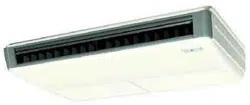
Nitrogen should be set to 2.9 psi with a pressure-reducing •
valve if brazing while inserting nitrogen into the pipe.
(Refer to Fig. 15)
Refrigerant pipe
Part to be
brazed
Taping
Pressure-reducing
valve
hands valve
Nitrogen
Nitrogen
Fig. 15
DANGER
Use of oxygen may cause an explosion resulting in serious •
injury or death. Only use nitrogen gas.
CAUTION
Be sure to insulate any fi eld piping all the way to the piping •
connection inside the unit. Any exposed piping may cause
condensate or a burn if touched.
PIPING INSULATION6-4
Make absolutely sure to execute thermal insulation works on •
the pipe-connecting section after checking gas leakage by
thoroughly studying the following fi gure and using the insula-
tion pipe cover (6) and (7). (Fasten both ends with the clamps
(4).) (Refer to Fig. 16)
Wrap the small sealing pad (9) only around the insulation for •
the joints on the gas piping side. (Refer to Fig. 16)
Insulation pipe cover for gas pipe (6)
Gas pipe
Liquid pipe
Insulation pipe cover for liquid pipe (7)
Clamp (4) (× 4)
Attach to the bottom
(For both gas pipe and liquid pipe)
Procedure for thermal insulation of liquid-side pipe
Insulation pipe cover for
liquid pipe (7)
Orient so that the end of
the wrapped insulation
material is facing up
Flare nut connection
Insulation pipe cover (main unit)
Attach to base
Main unit
Main unit
Clamp (4)
Clamp (4)
Insulation pipe cover
(Locally procured)
Procedure for thermal insulation of gas-side pipe
Insulation pipe cover
for gas pipe (6)
Insulation pipe
cover (main unit)
Attach to base
Orient so that the end of
the wrapped insulation
pipe cover is facing up
Flare nut connection
Insulation pipe cover
(Locally procured)
Wind around the
pipe, beginning at
the base.
Small sealing
pad (9)
Fig. 16
For piping facing back.(1)
Remove the rear metal plate for pipe. (Refer to Fig. 17)
The fi gure of the direction of back shows when both the pip- •
ing and drain pipe are set backward.
When setting the piping to face up or right, attach the rear
metal plate for refrigerant pipe and plug a hole for drain pipe.
(See “4 PREPARATIONS BEFORE INSTALLATION” (3-3) on
page 6)
For piping facing up.(2)
When setting the piping to face up, the L-shaped branch •
pipe kit sold separately is required.
Removing the top penetration lid and use the L-shaped branch •
pipe kit sold separately to set the pipe. (Refer to Fig. 18, 19)
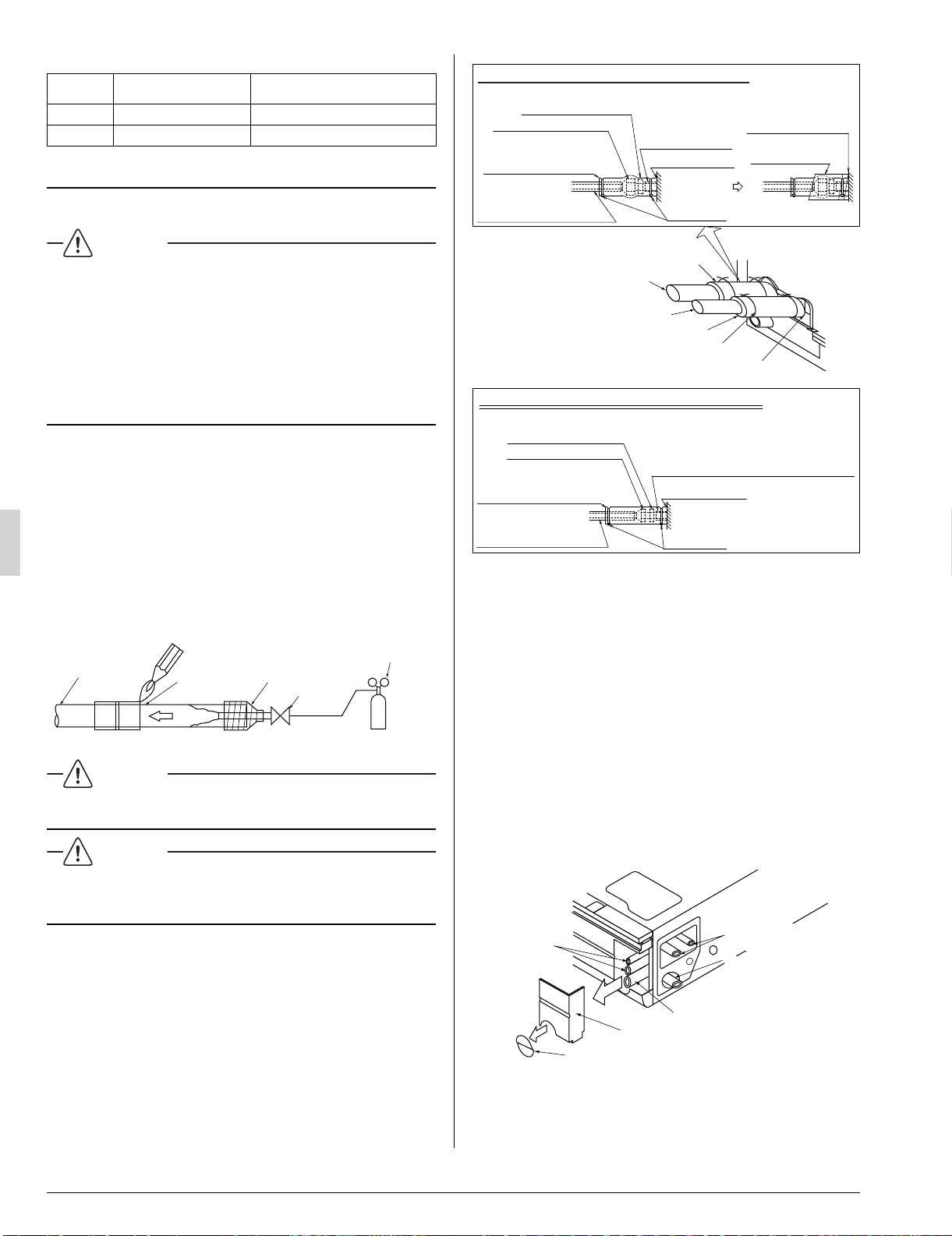
For piping facing right.(3)
Cut out a slit hole on the decoration panel (right) and set the •
pipe. (Refer to Fig. 17)
Right-facing drain pipe
Right-facing
refrigerant
piping
Decoration panel (right) removable part
If only setting the drain pipe to
face right, cut this section only.
Fig. 17
Rear-facing
refrigerant pipe
Rear right-facing
drain pipe
3PN0624012MEN.indd83PN0624012MEN.indd8 2008/12/2613:22:532008/12/2613:22:53
Loading ...
Loading ...
Loading ...