
English
Français
Español
OPERATION MANUAL
SPLIT SYSTEM Air Conditioners
MODEL
Ceiling suspended type
FHQ18PVJU
FHQ24PVJU
FHQ30PVJU
Read these instructions carefully before installation.
Keep this manual in a handy place for future reference.
This manual should be left with the equipment owner.
Lire soigneusement ces instructions avant l’installation.
Conserver ce manuel à portée de main pour référence ultérieure.
Ce manuel doit être donné au propriétaire de l’équipement.
Lea cuidadosamente estas instrucciones antes de instalar.
Guarde este manual en un lugar a mano para leer en caso de tener alguna duda.
Este manual debe permanecer con el propietario del equipo.
00_CV_3PN07753-11N.indd 100_CV_3PN07753-11N.indd 1 12/19/2008 7:43:45 PM12/19/2008 7:43:45 PM
[1]
TEST
F
hr
hr
TEST
NOT
AVAILABLE
L H
2
9
10
3
1
4
5
6
7
13
14
15
16
17
18
19
20
21
11
8
12
1
j
a
i
h
f
c
e
e
d
d
g
b
d
f
e
k
3
F
hr
H
2 4
00_CV_3PN07753-11N.indd Sec.1100_CV_3PN07753-11N.indd Sec.11 12/19/2008 7:43:46 PM12/19/2008 7:43:46 PM
1 English
CONTENTS
ILLUSTRATIONS .............................................. [1]
1. WHAT TO DO BEFORE OPERATION ......... 1
2. SAFETY CONSIDERATIONS ...................... 1
3. OPERATION RANGE ................................... 4
4. INSTALLATION SITE ................................... 4
5. NAME AND FUNCTION OF EACH SWITCH
AND DISPLAY ON THE REMOTE
CONTROLLER ............................................. 5
6. OPERATION PROCEDURE ........................ 5
7. OPTIMUM OPERATION .............................. 8
8. MAINTENANCE
(FOR SERVICE PERSONNEL) ................... 8
9. NOT MALFUNCTION OF THE AIR
CONDITIONER .......................................... 10
10. TROUBLE SHOOTING .............................. 11
WHAT TO DO BEFORE 1.
OPERATION
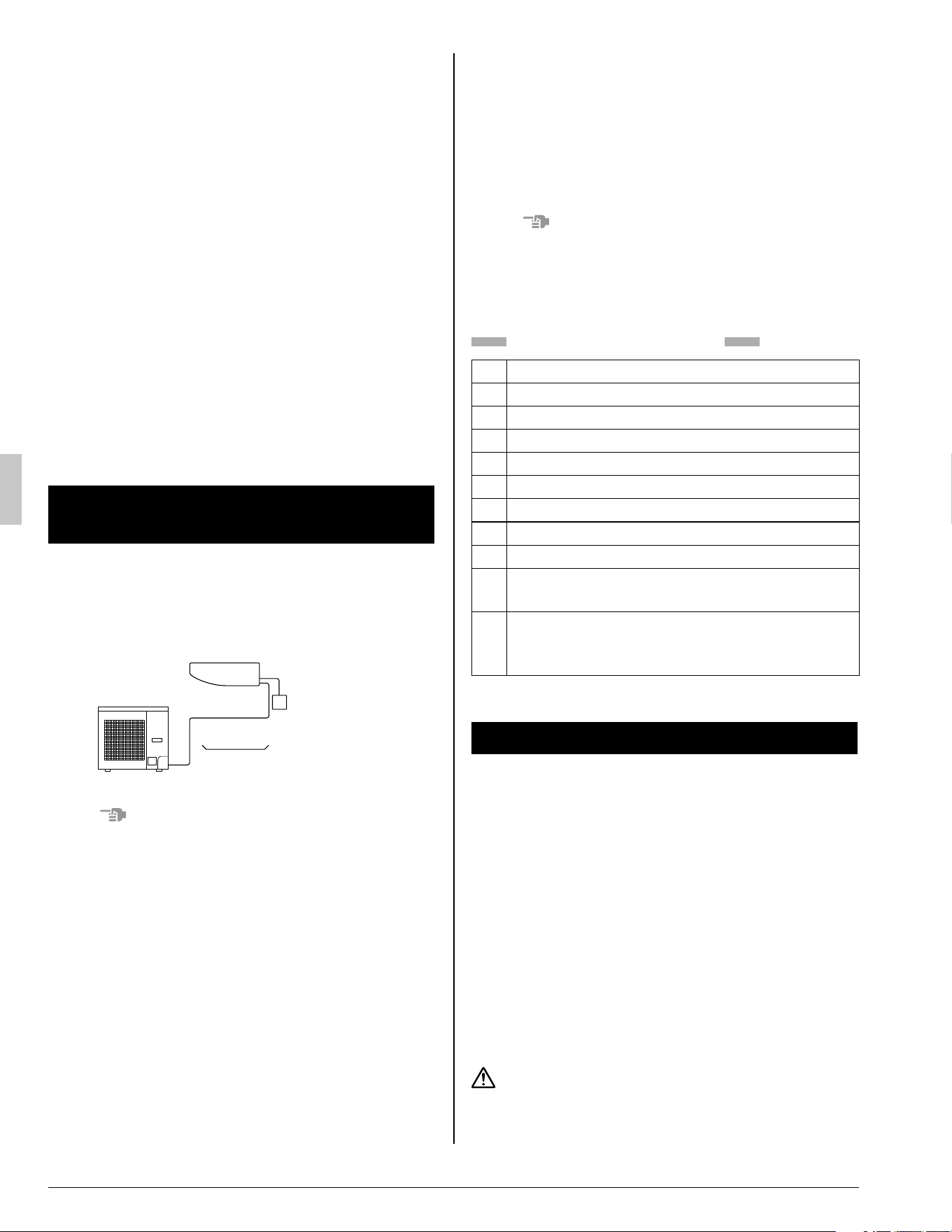
This operation manual is for the following system
with standard control. Before initiating operation,
contact your dealer for the operation that corre-
sponds to your system.
Indoor unit
Unit with remote controller
Outdoor unit
NOTE
If the unit you purchased is controlled by a wire-•
less remote controller, also refer to the wireless
remote controller’s operation manual.
If your installation has a customized control sys-
tem, ask your dealer for the operation that corre-
sponds to your system.
TWO REMOTE CONTROLLERS CONTROL
SYSTEM
Confi rm the following if your unit is the following
control system type.
2 remote controllers control system•
2 remote controllers control 1 indoor unit.
The unit is individually operated.
NOTE
Contact your dealer in case of 2 remote control-•
lers control system.
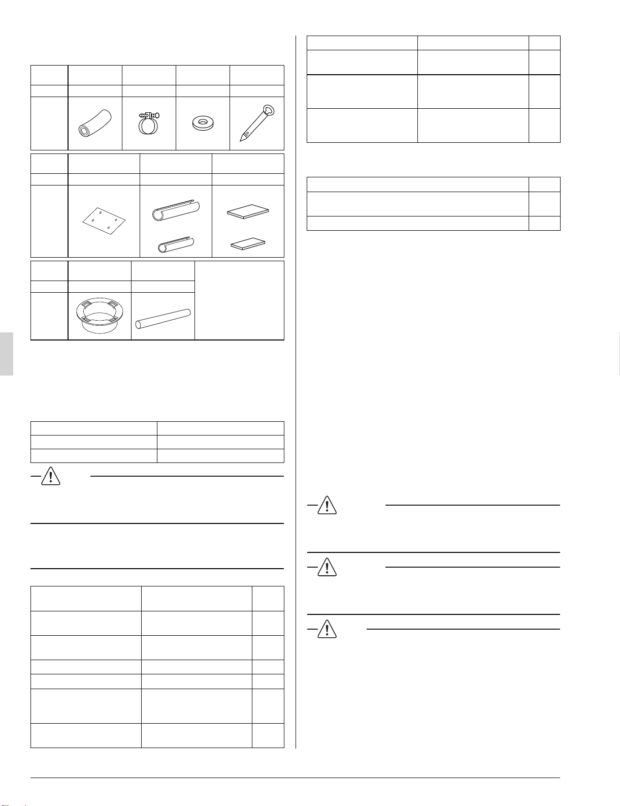
Names and functions of parts
Refer to Fig. 2 on page [1]
a
Indoor unit
b
Outdoor unit
c
Remote controller
d
Inlet air
e
Discharge air
f
Air outlet
g
Air fl ow fl ap (at air outlet)
h
Refrigerant pipe, connection electric wire
i
Drain pipe
j
Air inlet
The built-in air fi lter removes dust and dirt.
k
Ground wire
Wire to ground from the indoor and outdoor
unit to prevent electrical shocks.
SAFETY CONSIDERATIONS2.
Please read these “SAFETY CONSIDERATIONS”
carefully before installing air conditioning equip-
ment and be sure to install it correctly. After com-
pleting the installation, make sure that the unit
operates properly during the start-up operation.
Please instruct the customer on how to operate the
unit and keep it maintained.
Also, inform customers that they should store this
operation manual along with the installation manu-
al for future reference.
This air conditioner comes under the term “appli-
ances not accessible to the general public”.
Meaning of danger, warning, caution and note
symbols.
DANGER .......... Indicates an imminently haz-
ardous situation which, if not
avoided, will result in death or
serious injury.
01_EN_3PN07753-11N.indd 101_EN_3PN07753-11N.indd 1 12/19/2008 8:00:29 PM12/19/2008 8:00:29 PM
English 2
WARNING ........ Indicates a potentially hazard-
ous situation which, if not
avoided, could result in death
or serious injury.
CAUTION ......... Indicates a potentially hazard-
ous situation which, if not
avoided, may result in minor or
moderate injury. It may also be
sued to alert against unsafe
practices.
NOTE ................ Indicates situation that may
result in equipment or proper-
ty-damage-only accidents.
Keep these warning sheets handy so that you
can refer to them if needed.
Also, if this equipment is transferred to a new user,
make sure to hand over this operation manual to
the new user.
DANGER
Do not install the unit in an area where fl am-•
mable materials are present due to risk of
explosion resulting in serious injury or death.
Any abnormalities in the operation of the air •
conditioner such as smoke or fi re could re-
sult in severe injury or death.
Turn off the power and contact your dealer
immediately for instructions.
Refrigerant gas may product toxic gas if it •
comes in contact with fi re such a from a fan,
heater, stove or cooking device. Exposure to
this gas could cause severe injury or death.
For refrigerant leakage, consult your dealer.•
Refrigerant gas is heavier than air and replaces
oxygen. A massive leak could lead to oxygen
depletion, especially in basements, and an as-
phyxiation hazard could occur leading to serious
injury or death.
Safely dispose of the packing materials.•
Packing materials, such as nails and other metal
or wooden parts, may cause stabs or other inju-
ries.
Tear apart and throw away plastic packaging
bags so that children will not play with them.
Children playing with plastic bags face the dan-
ger of death by suffocation.
If equipment utilizing a burner is used in the •
same room as the air conditioner, there is
the danger of oxygen defi ciency which could
lead to an asphyxiation hazard resulting in
serious injury or death.
Be sure to ventilate the room suffi ciently to avoid
this hazard.
WARNING
It is not good for your health to expose your •
body to the air fl ow for a long time.
Ask your dealer for installation of the air •
conditioner.
Incomplete installation performed by yourself
may result in a water leakage, electric shock,
and fi re.
Ask your dealer for improvement, repair, and •
maintenance.
Incomplete improvement, repair, and mainte-
nance may result in a water leakage, electric
shock, and fi re.
Improper installation or attachment of equip-•
ment or accessories could result in electric
shock, short-circuit, leaks, fi re or other dam-
age to the equipment. Be sure only to use
accessories made by Daikin which are spe-
cifi cally designed for use with the equipment
and have them installed by a professional.
Ask your dealer to move and reinstall the air •
conditioner.
Incomplete installation may result in a water
leakage, electric shock, and fi re.
Never let the indoor unit or the remote con-•
troller get wet.
It may cause an electric shock or a fi re.
Never use fl ammable spray such as hair •
spray, lacquer or paint near the unit.
It may cause a fi re.
Never replace a fuse with that of wrong am-•
pere ratings or other wires when a fuse
blows out.
Use of wire or copper wire may cause the unit to
break down or cause a fi re.
Never remove the fan guard of the unit.•
A fan rotating at high speed without the fan
guard is very dangerous.
Never inspect or service the unit by yourself.•
Ask a qualifi ed service person to perform this
work.
Cut off all power supply before maintenance.•
To avoid the risk of serious electrical shock, •
never sprinkle or spill water or liquids on the
unit.
01_EN_3PN07753-11N.indd 201_EN_3PN07753-11N.indd 2 12/19/2008 8:00:30 PM12/19/2008 8:00:30 PM
3 English
Do not install the air conditioner at any place •
where fl ammable gas may leak out.
If the gas leaks out and stays around the air
conditioner, a fi re may break out.
Operating the air conditioner with wet hands •
could result in a shock hazard.
Check the unit stand for damage on a con-•
tinuous basis.
If left in a damaged condition the unit may fall
and cause injury.
Do not allow children to play on or around •
the unit as they could be injured.
Placing a fl ower vase or other containers •
with water or other liquids on the unit could
result in a shock hazard or fi re if a spill oc-
curs.
Do not put a fi nger or other objects into the •
air inlet or air outlet.
The fan is rotating at high speed and will
cause injury.
The heat exchanger fi ns are sharp enough to •
cut.
To avoid injury wear gloves or cover the fi ns
while working around them.
Be sure to establish an earth.•
Do not earth the unit to a utility pipe, arrester, or
telephone earth.
Incomplete earth may cause electrical shock, or
fi re.
A high surge current from lightning or other
sources may cause damage to the air condition-
er.
Be sure to install an earth leakage breaker.•
Failure to install an earth leakage breaker may
result in electric shocks, or fi re.
Never touch the internal parts of the control-•
ler.
Do not remove the front panel because some
parts inside are dangerous to touch. In addition,
some parts may be damaged. For checking and
adjusting internal parts, contact your dealer.
Do not touch the air outlet or horizontal •
blades while the swing fl ap is in operation
because fi ngers could get caught and in-
jured.
CAUTION
Do not use the air conditioner for other pur-•
poses.
In order to avoid any quality deterioration, do not
use the unit for cooling precision instruments,
food, plants, animals or works of art.
Do not place items under the indoor unit •
which may be damaged by water.
Condensation may form if the humidity is above
80%, or if the drain outlet gets blocked.
Avoid placing the controller in a spot •
splashed with water.
Water coming inside the air conditioner may
cause an electric leak or may damage the inter-
nal electronic parts.
Do not operate the air conditioner when us-•
ing a room fumigation - type insecticide.
Failure to observe could cause the chemicals to
become deposited in the unit, which could en-
danger the health of those who are hypersensi-
tive to chemicals.
Do not turn off the power immediately after •
stopping operation.
Always wait at least 5 minutes before turning off
the power. Otherwise, water leakage and trouble
may occur.
The appliance is not intended for use by •
young children or infi rm persons without
supervision.
The remote controller should be installed in •
such away that children cannot play with it.
Consult with installation contractor for clean-•
ing the inside of the air conditioner.
Wrong cleaning may make the plastics parts
broken or cause failure of water leakage or elec-
tric shock.
Do not touch the air inlet or aluminium fi n of •
the air conditioner.
Otherwise, injury may be caused.
Do not place objects in direct proximity of •
the outdoor unit and do not let leaves and
other debris accumulate around the unit.
Leaves are a hotbed for small animals which can
enter the unit. Once in the unit, such animals can
cause malfunctions, smoke or fi re when making
contact with electrical parts.
NOTE
Never press the button of the remote control-•
ler with a hard, pointed object.
The remote controller may be damaged.
Never pull or twist the electric wire of the •
remote controller.
It may cause the unit to malfunction.
Do not place appliances which produce open •
fi re in places exposed to the air fl ow from the
unit or under the indoor unit. It may cause
incomplete combustion or deformation of the
unit due to the heat.
01_EN_3PN07753-11N.indd 301_EN_3PN07753-11N.indd 3 12/19/2008 8:00:30 PM12/19/2008 8:00:30 PM
English 4
Arrange the drain pipe to ensure smooth •
drainage. Incomplete drainage may cause
wetting of the building, furniture etc.
Do not place the controller exposed to direct •
sunlight.
The LCD display may get discolored, failing to
display the data.
Do not wipe the controller operation panel •
with benzine, thinner, chemical dustcloth, etc.
The panel may get discolored or the coating
peeled off. If it is heavily dirty, soak a cloth in
water-diluted neutral detergent, squeeze it well
and wipe the panel clean. And wipe it with an-
other dry cloth.
Dismantling of the unit, treatment of the re-•
frigerant, oil and eventual other parts, should
be done in accordance with the relevant local
and national regulations.
Do not dry the fi lter by exposing it to direct •
sunlight or warming it using fi re, etc. Doing
so can result in the deformation of the fi lter.
OPERATION RANGE3.
If the temperature or the humidity is beyond the
following conditions, safety devices may work and
the air conditioner may not operate, or sometimes,
water may drop from the indoor unit.
OUTDOOR
UNIT
OPERATION
TEMPERATURE (°F)
OUTDOOR INDOOR
RZQ18·24·
30PVJU
COOLING 23 to 115 (DB) 57 to 77 (WB)
HEATING 0 to 60 (WB) 59 to 80.5 (DB)
D B: Dry bulb temperature (°F)
WB: Wet bulb temperature (°F)
The setting temperature range of the remote con-
troller is 60°F to 90°F.
INSTALLATION SITE4.
Regarding places for installation
Is the air conditioner installed at a well-venti-•
lated place where there are no obstacles
around?
Do not use the air conditioner in the follow-•
ing places.
a. Filled with much mineral oil such as cutting oil
b. Where there is much salt such as a beach
area
c. Where sulfured gas exists such as a hot-
spring resort
d. Where there are considerable voltage fl uctua-
tions such as a factory or plant
e. Vehicles and vessels
f . Where there is much spray of oil and vapor
such as a cookery, etc.
g. Where there are machines generating electro-
magnetic waves
h. Filled with acid and/or alkaline steam or vapor
Is a snow protection measure taken?•
For details, consult your dealer.
Regarding wiring
All wiring must be performed by an autho-•
rized electrician.
To do wiring, ask your dealer. Never do it by
yourself.
Make sure that a separate power supply cir-•
cuit is provided for this air conditioner and
that all electrical work is carried out by quali-
fi ed personnel according to local laws and
regulations.
Pay attention to running noises, too
Are the following places selected?•
a. A place that can suffi ciently withstand the
weight of the air conditioner with less running
noises and vibrations.
b. A place where the hot wind discharged from
the air outlet of the outdoor unit and the run-
ning noises.
Are you sure that there are no obstacles near •
the air outlet of the outdoor unit?
Such obstacles may result in declined perfor-
mance and increased running noises.
If abnormal noises occur in use, consult your •
dealer.
01_EN_3PN07753-11N.indd 401_EN_3PN07753-11N.indd 4 12/19/2008 8:00:30 PM12/19/2008 8:00:30 PM
5 English
Regarding drainage of drain pipe
Is the drain pipe executed to perform com-•
plete drainage?
If proper drainage is not carried out from the
outdoor drain pipes during air-conditioning op-
eration, chances are that dust and dirt are
clogged in the pipe. This may result in a water
leakage from the indoor unit. Under such circum-
stances, stop the operation of the air conditioner,
and then consult your dealer or our service sta-
tion.
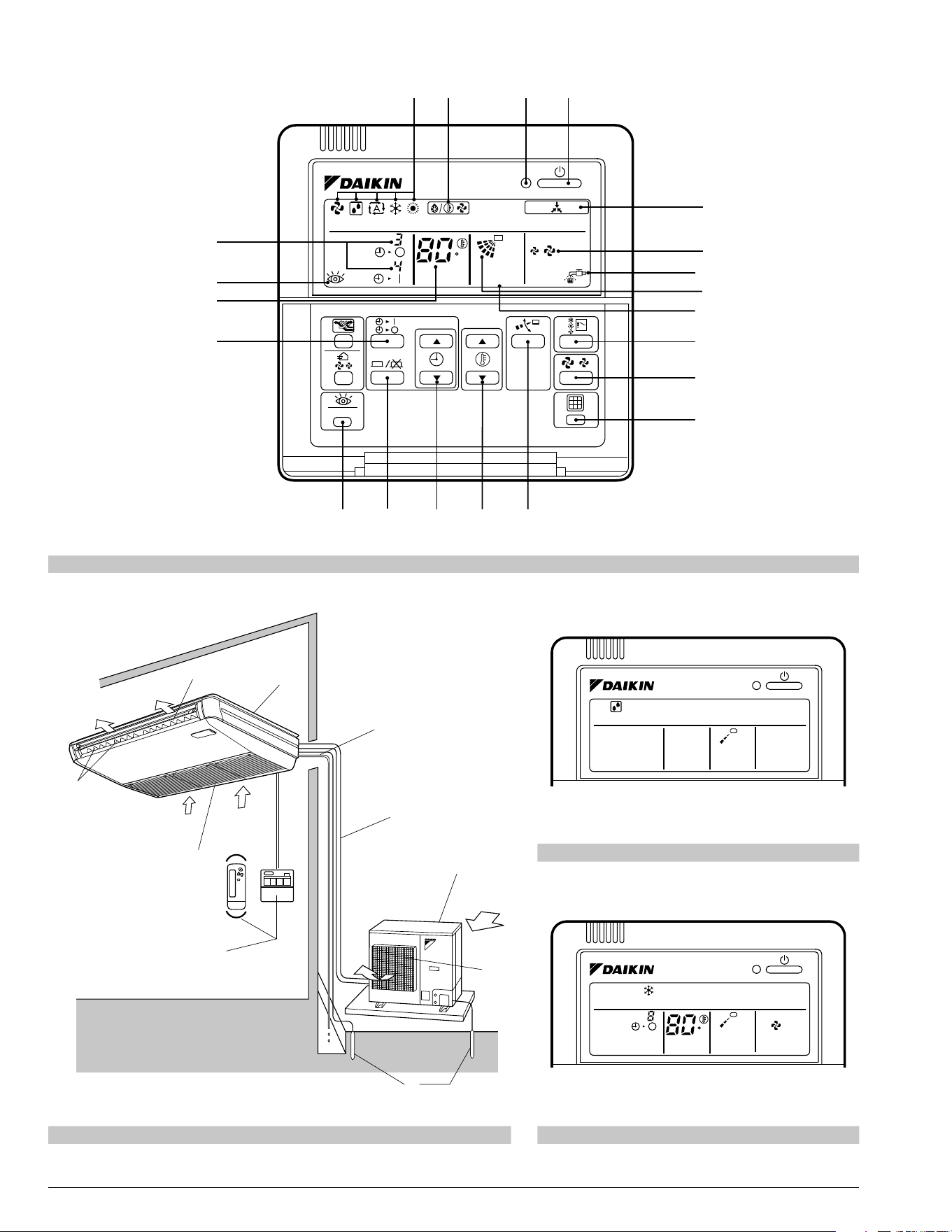
NAME AND FUNCTION OF 5.
EACH SWITCH AND DISPLAY
ON THE REMOTE CONTROLLER
Refer to Fig. 1 on page [1]
The illustrations in this operating manual corre-
spond to the remote control format BRC1C type.
1
ON/OFF BUTTON
Press the button and the system will start.
Press the button again and the system will
stop.
2
OPERATION LAMP (RED)
The lamp lights up during operation.
3
DISPLAY “
” (UNDER CENTRAL-
IZED CONTROL)
When this display shows, the system is UN-
DER CENTRALIZED CONTROL.
4
DISPLAY “
” “ ” “ ” “ ” “ ”
(OPERATION MODE)
This display shows the current OPERATION
MODE.
5
DISPLAY “
TEST ” (INSPECTION/TEST
OPERATION)
When the INSPECTION/TEST OPERATION
BUTTON is pressed, the display shows the
system mode is in.
6
DISPLAY “
” (PROGRAMMED TIME)
This display shows the PROGRAMMED
TIME of the system start or stop.
7
DISPLAY “
” (SET TEMPERATURE)
This display shows the set temperature.
8
DISPLAY “
” (FAN SPEED)
This display shows the set fan speed.
9
DISPLAY “
” (AIR FLOW FLAP)
Refer to “AIR FLOW DIRECTION ADJUST”.
10
DISPLAY “
” (TIME TO CLEAN AIR
FILTER)
Refer to “HOW TO CLEAN THE AIR FILTER”.
11
DISPLAY “
” (DEFROST)
Refer to “DEFROST OPERATION”.
12
NON-FUNCTIONING DISPLAY
If that particular function is not available,
pressing the button may display the words
“NOT AVAILABLE” for a few seconds.
13
TIMER MODE START/STOP BUTTON
Refer to “PROGRAM TIMER OPERATION”.
14
TIMER ON/OFF BUTTON
Refer to “PROGRAM TIMER OPERATION”.
15
INSPECTION/TEST OPERATION BUTTON
This button is used only by qualifi ed service
persons for maintenance purposes.
16
PROGRAMMING TIME BUTTON
Use this button for programming “START
and/or STOP” time.
17
TEMPERATURE SETTING BUTTON
Use this button for SETTING TEMPERA-
TURE.
18
FILTER SIGN RESET BUTTON
Refer to “HOW TO CLEAN THE AIR FILTER”.
19
FAN SPEED CONTROL BUTTON
Press this button to select the fan speed,
HIGH or LOW, of your choice.
20
OPERATION MODE SELECTOR BUTTON
Press this button to select OPERATION
MODE.
21
AIR FLOW DIRECTION ADJUST BUTTON
Refer to “AIR FLOW DIRECTION ADJUST”.
NOTE
For the sake of explanation, all indications are •
shown on the display in Fig. 1 on page [1] con-
trary to actual running situations.
OPERATION PROCEDURE6.
Refer to Fig. 1 on page [1]
To protect the unit, turn on the main power •
switch 6 hours before operation.
If the main power supply is turned off during •
operation, operation will restart automatically
after the power turns back on again.
01_EN_3PN07753-11N.indd 501_EN_3PN07753-11N.indd 5 12/19/2008 8:00:30 PM12/19/2008 8:00:30 PM
English 6
COOLING, HEATING, AUTOMATIC, FAN,
AND PROGRAM DRY OPERATION
Operate in the following order.
1
OPERATION MODE
SELECTOR
Press OPERATION MODE SELECTOR
button several times and select the
OPERATION MODE of your choice as
follows.
COOLING OPERATION ............................... “ ”
HEATING OPERATION ................................. “
”
AUTOMATIC OPERATION ............................ “
”
In this operation mode, COOL/HEAT change-•
over is automatically conducted.
FAN OPERATION ......................................... “
”
DRY OPERATION ......................................... “
”
The function of this program is to decrease the •
humidity in your room with the minimum tem-
perature decrease.
Micro computer automatically determines •
TEMPERATURE and FAN SPEED.
This system does not go into operation if the •
room temperature is below 60°F.
Refer to Fig. 3 on page [1]
2
ON/OFF
Press ON/OFF button.
OPERATION lamp lights up or goes off and the
system starts or stops OPERATION.
[EXPLANATION OF HEATING OPERATION]
DEFROST OPERATION
As the frost on the coil of an outdoor unit in-•
crease, heating effect decreases and the system
goes into DEFROST OPERATION.
The indoor unit fan stops and the remote control-•
ler display shows “
”.
After 6 to 8 minutes (maximum 10 minutes) of •
DEFROST OPERATION, the system returns to
HEATING OPERATION.
Regarding outside air temperature and
heating capacity
The heating capacity of the air conditioner de-•
clines as the outside air temperature falls. In this
case, use the air conditioner in combination with
other heating systems.
A warm air circulating system is employed, and •
therefore it takes some time until the entire room
is warmed up after the start of operation.
An indoor fan runs to discharge a gentle wind •
automatically until the temperature inside the air
conditioner reaches a certain level. At this time,
the remote controller displays “
”. Leave it
as it stands and wait for a while.
When the warm air stays under the ceiling and •
your feet are cold, we recommend that you use a
circulator (a fan to circulate the air inside the
room). For details, consult your dealer.
ADJUSTMENT
For programming TEMPERATURE, FAN SPEED
and AIR FLOW DIRECTION, follow the procedure
shown below.
TEMPERATURE SETTING
Press TEMPERATURE SETTING button and
program the setting temperature.
Each time this button is pressed,
setting temperature rises 1°F.
Each time this button is pressed,
setting temperature lowers 1°F.
The setting is impossible for fan operation.•
NOTE
The setting temperature range of the remote •
controller is 60°F to 90°F.
FAN SPEED CONTROL
Press FAN SPEED CONTROL button.
High or Low fan speed can be selected.
The micro computer may sometimes control the
fan speed in order to protect the unit.
01_EN_3PN07753-11N.indd 601_EN_3PN07753-11N.indd 6 12/19/2008 8:00:31 PM12/19/2008 8:00:31 PM
7 English
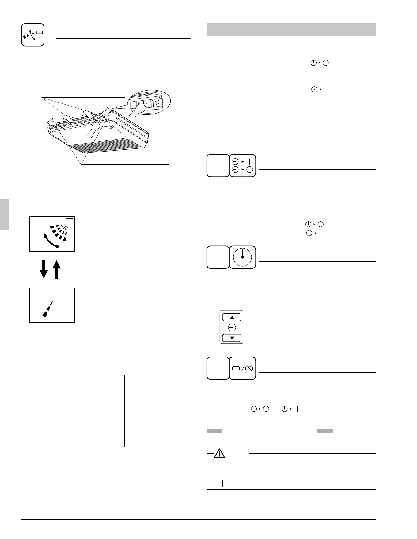
AIR FLOW DIRECTION ADJUST
There are 2 ways of adjusting the air discharge •
angle.
A. Up and down direction1.
B. Left and right direction2.
A. Up and down direction
B. Left and right direction
A. UP AND DOWN DIRECTION
Press the AIR FLOW DIRECTION ADJUST
button to select the air direction as shown
below.
swing
The AIR FLOW FLAP display
swings as shown below and the
air fl ow direction continuously
varies. (Automatic swing setting)
Press AIR FLOW DIRECTION
ADJUST button to select the air
direction of your choice.
The AIR FLOW FLAP display
stops swinging and the air fl ow
direction is fi xed (Fixed air fl ow
direction setting).
MOVEMENT OF THE AIR FLOW FLAP
For the following conditions, micro computer con-
trols the air fl ow direction so it may be different
from the display.
Operation
mode
Cooling Heating
Operation
condition
When operating •
continuously at
downward air
fl ow direction
When room •
temperature is
higher than the
set temperature
At defrost opera-•
tion
Operation mode includes automatic operation.
PROGRAM TIMER OPERATION
Operate in the following order.
The timer is operated in the following two ways.•
Programming the stop time ( • ) ....
The system stops operating after the set time
has elapsed.
Programming the start time ( •
) ....
The system starts operating after the set time
has elapsed.
The timer can be programmed a maximum of •
72 hours.
The start and the stop time can be simultane-•
ously programmed.
1
TIMER MODE START/STOP
Press the TIMER MODE START/STOP
button several times and select the mode
on the display.
The display fl ashes.
For setting the timer stop .... “
”
For setting the timer start .... “
”
2
PROGRAMMING TIME
Press the PROGRAMMING TIME button and
set the time for stopping or starting the
system.
When this button is pressed, the time
advances by 1 hour.
When this button is pressed, the time
goes backward by 1 hour.
3
TIMER ON/OFF
Press the TIMER ON/OFF button.
The timer setting procedure ends.
The display “
or ” changes from fl ash-
ing light to a constant light.
Refer to Fig. 4 on page [1]
NOTE
When setting the timer Stop and Start at the •
same time, repeat the above procedure from
1
to
3
once again.
01_EN_3PN07753-11N.indd 701_EN_3PN07753-11N.indd 7 12/19/2008 8:00:31 PM12/19/2008 8:00:31 PM
English 8
When the timer is programmed to stop the system
after 3 hours and start the system after 4 hours,
the system will stop after 3 hours and then 1 hour
later the system will start.
After the timer is programmed, the display shows •
the remaining time.
Press the TIMER ON/OFF button once again to •
cancel programming. The display vanishes.
OPTIMUM OPERATION7.
Observe the following precautions to ensure the
system operates.
Adjust the room temperature properly for a com-•
fortable environment. Avoid excessive heating or
cooling.
Prevent direct sunlight from entering a room •
during cooling operation by using curtains or
blinds.
Ventilate the room regularly.•
Using the unit for long periods of time requires
attentive ventilation of the room.
Keep doors and windows closed. If the doors •
and windows remain open, room air will fl ow out
and cause to decrease the effect of cooling and
heating.
Do not place other heaters directly below the •
indoor unit.
They may deform due to the heat.
Never place objects near the air inlet and the air •
outlet of the unit. It may cause deterioration in
the effect or stop in the operation.
Turn off the main power supply switch when it is •
not used for long periods of time. When the main
power switch is turned on, some watts of elec-
tricity is being used even if the system is not
operating. Turn off the main power supply switch
for saving energy. When reoperating, turn on the
main power supply switch 6 hours before opera-
tion for smooth running (Refer to “MAINTE-
NANCE”).
When the display shows “ •
” (TIME TO
CLEAN AIR FILTER), ask a qualifi ed service
person to clean the fi lters (Refer to “MAINTE-
NANCE”).
MAINTENANCE8.
(FOR SERVICE PERSONNEL)
ONLY A QUALIFIED SERVICE PERSON IS
ALLOWED TO PERFORM MAINTENANCE
IMPORTANT!
BEFORE OBTAINING ACCESS TO TERMINAL •
DEVICES, ALL POWER SUPPLY CIRCUITS
MUST BE INTERRUPTED
To clean the air conditioner, be sure to stop op-•
eration, and turn the power switch off. Otherwise,
an electric shock and injury may result.
Do not wash the air conditioner with water.•
Doing so may result in an electric shock.
Be careful with a scaffold or staging.•
Caution must be exercised because of work at a
high place.
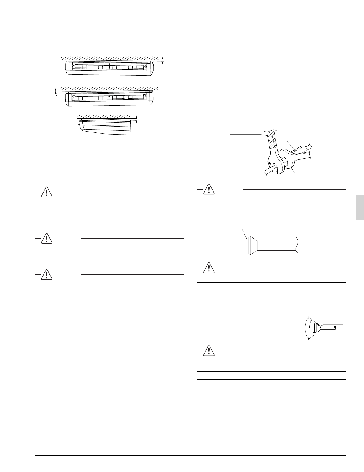
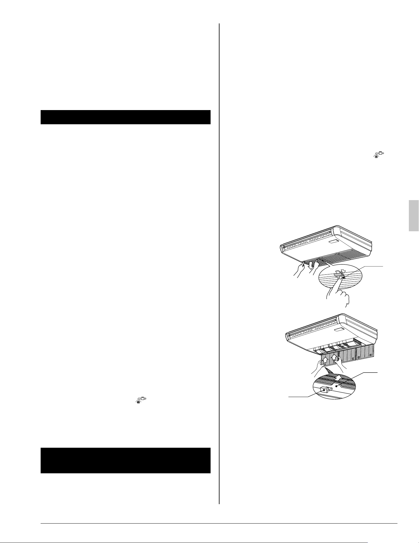
HOW TO CLEAN THE AIR FILTER
Clean the air fi lter when the display shows “ ”
(TIME TO CLEAN AIR FILTER).
Increase the frequency of cleaning if the unit is
installed in a room where the air is extremely
contaminated.
If the dirt becomes impossible to clean, change the
air fi lter (Contact your dealer when you exchange
air fi lter.).
Fig.5
Knob
Fig.6
Ta b
Hook
Open the suction grille.1.
Slide knobs (×2) simultaneously as shown and
then pull them downward. (Do the same proce-
dure for closing.) (Refer to Fig. 5)
Remove the air fi lters.2.
Push the 2 tabs up, and remove slowly lower
the air fi lter. (Refer to Fig. 6)
01_EN_3PN07753-11N.indd 801_EN_3PN07753-11N.indd 8 12/19/2008 8:00:32 PM12/19/2008 8:00:32 PM
9 English
Clean the air fi lter.3.
Use vacuum cleaner A) or wash the air fi lter
with water B).
A) Using a vacuum cleaner
(Do not use air of 120°F or
higher.)
B) Washing with water
When the air fi lter is very dirty,
use soft brush and neutral
detergent.
(Do not use water of 120°F or
higher.)
Remove water and dry in the shade.
NOTE
Do not wash the air conditioner with hot water of •
more than 120°F, as doing so may result in dis-
coloration and/or deformation.
Do not expose it to fi re, as doing so may result in •
burning.
Fix the air fi lter.4.
Set the tab of the air fi lter to the hook of the
suction grille, and fi x the air fi lter. (By the meth-
od opposite to removing.)
Shut the suction grille by the method oppo-5.
site to opening.
Press the FILTER SIGN RESET BUTTON on 6.
the remote controller.
The display “
” (TIME TO CLEAN AIR FIL-
TER) vanishes.
HOW TO CLEAN AIR OUTLET AND
OUTSIDE PANELS
Clean with soft cloth•
When it is diffi cult to remove stains, use water or •
neutral detergent.
WARNING
Do not let the indoor unit get wet as it may cause •
an electric shock or fi re.
NOTE
Do not use gasoline, benzene, thinner, polishing •
powder, liquid insecticide. It may cause discolor-
ing or warping.
Do not scrub fi rmly when washing the blade with •
water.
The surface sealing may peel off.
Do not use water or air of 120 • °F or higher for
cleaning air fi lters and outside panels.
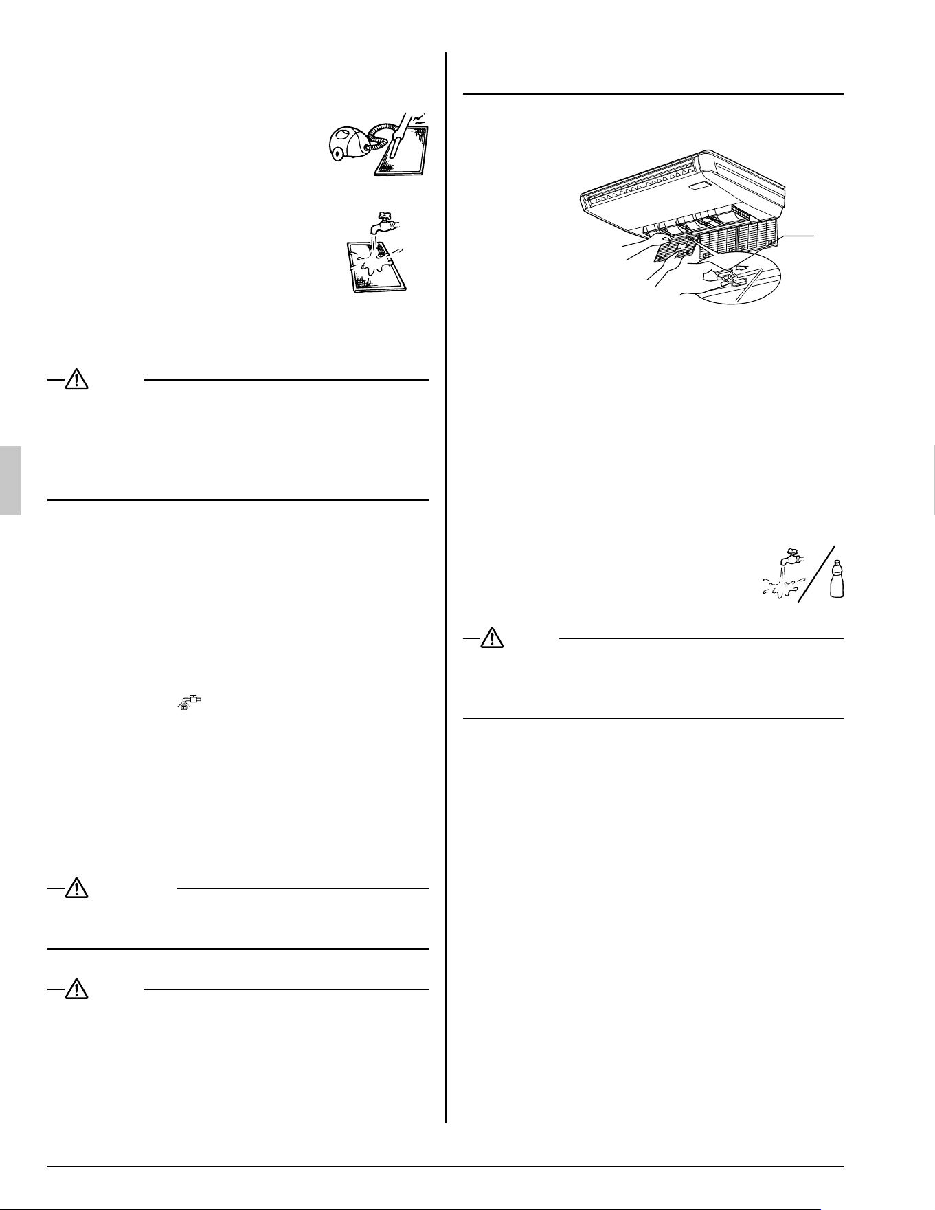
HOW TO CLEAN THE SUCTION GRILLE
Fig.7
Clip
Open the suction grille.1.
Refer to “HOW TO CLEAN THE AIR FILTER”.
(Refer to Fig. 5)
Remove the air fi lter.2.
Refer to “HOW TO CLEAN THE AIR FILTER”.
(Refer to Fig. 6)
Detach the suction grille.3.
Pull the clips (×2) on the back of the suction
grille forward. (Refer to Fig. 7)
4. Clean the suction grille.
Wash with a soft bristle brush and
neutral detergent or water, and dry
throughly.
NOTE
Do not wash the suction grille with hot water of •
more than 120°F, as doing so may result in dis-
coloration and/or deformation.
Fix the air fi lter.5.
Refer to “HOW TO CLEAN THE AIR FILTER”.
Attach the suction grille by the method 6.
opposite to removing.
Shut the suction grille by the method oppo-7.
site to opening.
START UP AFTER A LONG STOP
Confi rm the following
Check that the air inlet and outlet are not •
blocked.
Remove any obstacle.
Check if the earth is connected.•
Might there be a broken wire somewhere?
Contact your dealer if there are any problems.
01_EN_3PN07753-11N.indd 901_EN_3PN07753-11N.indd 9 12/19/2008 8:00:32 PM12/19/2008 8:00:32 PM
English 10
Clean the air fi lter and outside panels
After cleaning the air fi lter, make sure to attach it.•
Turn on the main power supply switch
The display on the remote controller will be •
shown when the power is turned on.
To protect the unit, turn on the main power •
switch at least 6 hours before operation.
WHAT TO DO WHEN STOPPING THE
SYSTEM FOR A LONG PERIOD
Turn on FAN OPERATION for a half day and dry
the unit.
Refer to “FAN OPERATION”.•
Cut off the power supply.
When the main power switch is turned on, some •
watts of electricity is being used even if the sys-
tem is not operating.
Turn off the main power supply switch for saving
energy.
The display on the remote controller will vanish •
when the main power switch is turned off.
Clean the air fi lter and the exterior.
Be sure to replace the air fi lter to its original •
place after cleaning. Refer to “MAINTENANCE”.
NOT MALFUNCTION OF THE AIR 9.
CONDITIONER
The following symptoms do not indicate air condi-
tioner malfunction.
THE SYSTEM DOES NOT OPERATEI.
The system does not restart immediately •
after the ON/OFF button is pressed.
If the OPERATION lamp lights, the system is in
normal condition.
It does not restart immediately because a
safety device operates to prevent overload of
the system. After 3 minutes, the system will
turn on again automatically.
The system does not restart immediately •
when TEMPERATURE SETTING button is
returned to the former position after push-
ing the button.
If the OPERATION lamp lights, the system is in
normal condition.
It does not restart immediately because a
safety device operates to prevent overload of
the system. After 3 minutes, the system will
turn on again automatically.
The system does not start when the display •
shows “
” (UNDER CENTRALIZED
CONTROL) and it fl ashes for a few seconds
after pressing an operation button.
This is because the system is under central-
ized control. Flashes on the display indicates
that the system cannot be controlled by the
remote controller.
The system does not start immediately •
after the power supply is turned on.
At least wait 5 minutes until the micro comput-
er is prepared for operation.
The outdoor unit is stopped•
This is because the room temperature has
reached the set temperature. The indoor unit
switches to fan operation.
This is to prevent the cool air from being blown
directly onto anyone in the room.
AIR FLOW DIRECTION IS NOT AS SPECI-II.
FIED.
Actual air blow direction is not as shown on •
the remote controller.
Automatic swing setting does not work.•
Refer to “AIR FLOW DIRECTION ADJUST”.
WHITE MIST COMES OUT OF A UNITIII.
When humidity is high during cooling op-•
eration. (In oily or dusty places)
If the inside of an indoor unit is extremely con-
taminated, the temperature distribution inside a
room becomes uneven. It is necessary to clean
the inside of the indoor unit. Ask your dealer for
details on cleaning the unit. This operation
requires a qualifi ed service person.
When the system is changed over to HEAT-•
ING OPERATION after DEFROST OPERA-
TION.
Moisture generated by DEFROST becomes
steam and exists.
NOISE OF AIR CONDITIONERSIV.
A ringing sound after the unit is started.•
This sound is generated by the temperature
regulator working.
It will quiet down after about a minute.
A continuous fl ow “Shuh” sound is heard •
when the systems is in COOLING or DE-
FROST OPERATION.
This is the sound of refrigerant gas fl owing
through both indoor and outdoor units.
01_EN_3PN07753-11N.indd 1001_EN_3PN07753-11N.indd 10 12/19/2008 8:00:33 PM12/19/2008 8:00:33 PM
11 English
A “Shuh” sound which is heard at the start •
or immediately after the stop of operation
or which is heard at the start or immediate-
ly after the stop of DEFROST OPERATION.
This is the noise of refrigerant caused by fl ow
stop and fl ow change.
A “Pishi-pishi” squeaking sound is heard •
when the system is in operation or after the
stop of operation.
Expansion and contraction of plastic parts
caused by temperature change makes this
noise.
DUST FROM THE UNITSV.
Dust may blow out from the unit after start-•
ing operation from long resting time.
Dust absorbed by the unit blows out.
THE UNITS GIVE OFF ODORSVI.
The unit absorbs the smell of rooms, furniture,
cigarettes, etc., and then emits them.
THE LIQUID CRYSTAL OF THE REMOTE VII.
CONTROLLER SHOW “
”
It happens immediately after the main pow-•
er supply switch is turned on.
This shows that the remote controller is in
normal condition.
This continues temporary.
TROUBLE SHOOTING10.
If one of the following malfunctions occurs, I.
take the measures shown below and contact
your dealer.
The system must be repaired by a qualifi ed service
person.
WARNING
When the air conditioner is in abnormal con-•
ditions (smell of something burning, etc),
unplug the power cord from the outlet, and
contact your dealer
Continued operation under such circumstances
may result in a failure, electric shock, and fi re.
If a safety device such as a fuse, a breaker or an •
earth leakage breaker frequently actuates;
Measure: Do not turn on the main power switch.
If the ON/OFF switch does not properly work;•
Measure: Turn off the main power switch.
If water leaks from unit.•
Measure: Stop the operation.
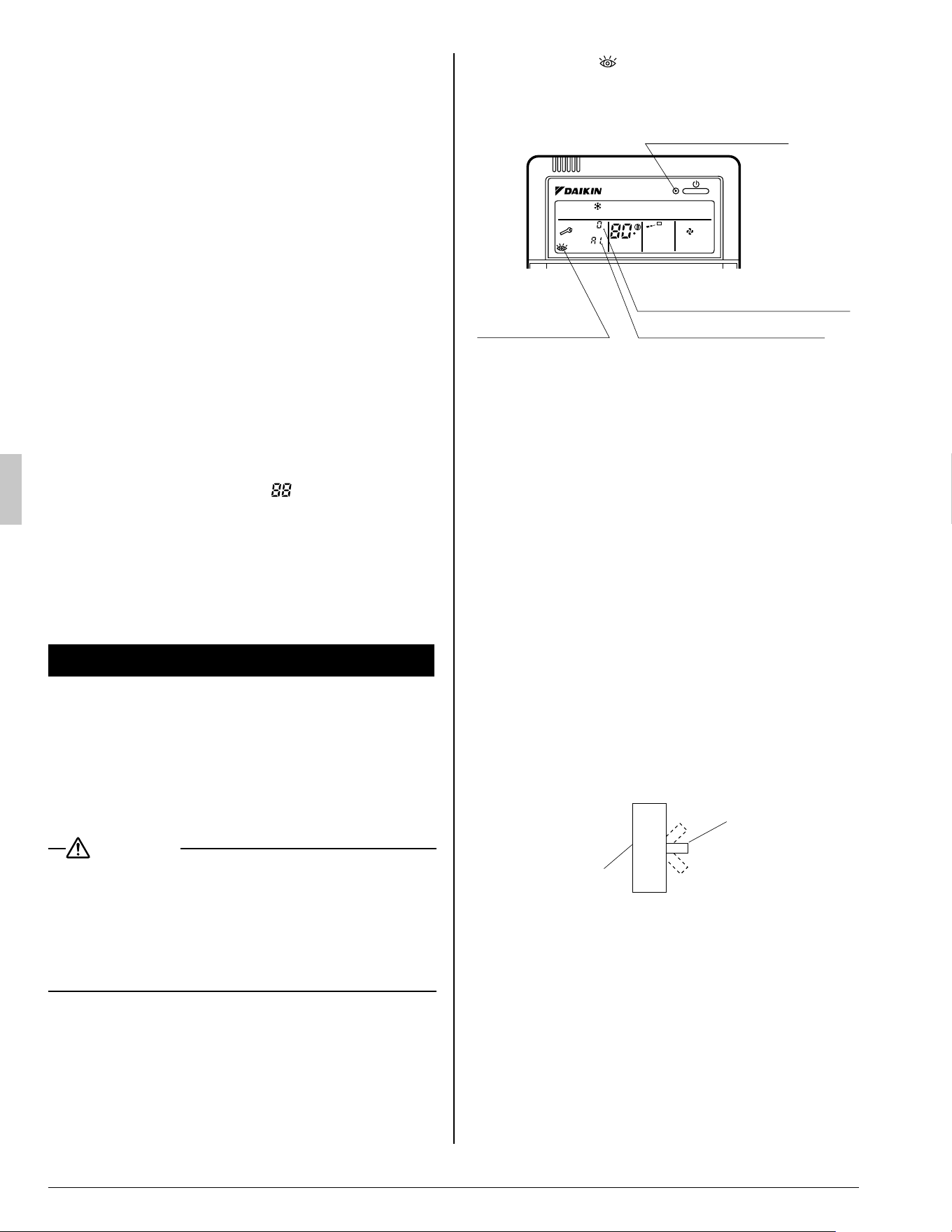
If the display “ •
” (INSPECTION), “UNIT No.”,
and the OPERATION lamp fl ash and the “MAL-
FUNCTION CODE” appears.
OPERATION lamp
INSPECTION
display
MALFUNCTION CODE
INDOOR UNIT No. in
which a malfunction occurs
UNIT No.
F
L H
Measure: Notify your dealer and inform him/her
of the display.
If the system does not properly operate II.
except for the above mentioned case, and
none of the above mentioned malfunctions
is evident, investigate the system according
to the following procedures.
If the system does not operate at all.1.
Check if there is a power failure.•
Wait until power is restored. If power failure
occurs during operation, the system auto-
matically restarts immediately after the power
supply recovers.
Check if a fuse has blown.•
Turn off the power supply.
Is the breaker blown?•
Turn the power on with the breaker switch in
the off position.
Do not turn the power on with the breaker
switch in the trip position.
(Contact your dealer.)
Switch
ON
OFF
Trip position
Breaker
If the system stops operating after operat-2.
ing the system.
Check if the air inlet or outlet of outdoor or •
indoor unit is blocked by obstacles.
Remove the obstacle and make it well-venti-
lated.
Check if the air fi lter is clogged.•
Ask a qualifi ed service person to clean the
air fi lters.
(Refer to “MAINTENANCE”)
01_EN_3PN07753-11N.indd 1101_EN_3PN07753-11N.indd 11 12/19/2008 8:00:33 PM12/19/2008 8:00:33 PM

English 12
The system operates but it does not suffi -3.
ciently cool or heat.
If the air inlet or outlet of the indoor or the •
outdoor unit is blocked with obstacles.
Remove the obstacle and make it well-venti-
lated.
If the air fi lter is clogged.•
Ask a qualifi ed service person to clean the
air fi lters.
(Refer to “MAINTENANCE”)
If the set temperature is not proper. •
(Refer to “ADJUSTMENT”)
If the FAN SPEED button is set to LOW •
SPEED.
(Refer to “ADJUSTMENT”)
If the air fl ow direction is not proper. •
(Refer to “AIR FLOW DIRECTION ADJUST”)
If the doors or the windows are open. •
Shut doors or windows to prevent wind from
coming in.
If direct sunlight enters the room (when cool-•
ing).
Use curtains or blinds.
When there are too many inhabitants in the •
room (when cooling).
Cooling effect decreases if heat gain of the
room is too large.
If the heat source of the room is excessive •
(when cooling).
Cooling effect decreases if heat gain of the
room is too large.
01_EN_3PN07753-11N.indd 1201_EN_3PN07753-11N.indd 12 12/19/2008 8:00:33 PM12/19/2008 8:00:33 PM
3PN07753-11N
EM08A092
(0902)
HT
00_CV_3PN07753-11N.indd 200_CV_3PN07753-11N.indd 2 12/19/2008 7:43:46 PM12/19/2008 7:43:46 PM