
P360 Ultra
User Guide

Read this first
Before using this documentation and the product it supports, ensure that you read and understand the
following:
• Safety and Warranty Guide
• Generic Safety and Compliance Notices
• Setup Guide
First Edition (June 2022)
© Copyright Lenovo 2022.
LIMITED AND RESTRICTED RIGHTS NOTICE: If data or software is delivered pursuant to a General Services
Administration “GSA” contract, use, reproduction, or disclosure is subject to restrictions set forth in Contract No. GS-
35F-05925.

Contents
Discover your Lenovo computer . . . . iii
Chapter 1. Meet your computer. . . . . 1
Front . . . . . . . . . . . . . . . . . . . . 1
Rear . . . . . . . . . . . . . . . . . . . . 3
Features and specifications . . . . . . . . . . . 5
USB specifications . . . . . . . . . . . . . . 6
Chapter 2. Get started with your
computer . . . . . . . . . . . . . . . . . 7
Get started with Ubuntu Desktop . . . . . . . . . 7
Access networks . . . . . . . . . . . . . . . 7
Connect to the wired Ethernet . . . . . . . . 7
Connect to Wi-Fi networks (for selected
models) . . . . . . . . . . . . . . . . . 7
Connect an external display . . . . . . . . . . . 8
Manage cables with a smart cable clip . . . . . . . 8
Chapter 3. Explore your computer . . . 9
Set the power plan . . . . . . . . . . . . . . 9
Transfer data . . . . . . . . . . . . . . . . . 9
Connect to a Bluetooth-enabled device (for
selected models) . . . . . . . . . . . . . . . 9
Purchase accessories . . . . . . . . . . . . 10
Chapter 4. Secure your computer
and information . . . . . . . . . . . . 11
Lock the computer . . . . . . . . . . . . . 11
UEFI BIOS passwords . . . . . . . . . . . . 11
Certificate based BIOS management . . . . . . 12
Computrace Agent software embedded in
firmware (for selected models) . . . . . . . . . 13
Use BIOS security solutions . . . . . . . . . . 13
Wipe the storage drive data . . . . . . . . 13
Cover presence switch . . . . . . . . . . 14
Intel BIOS guard . . . . . . . . . . . . . 14
Smart USB Protection . . . . . . . . . . 14
Chapter 5. UEFI BIOS . . . . . . . . . 15
What is UEFI BIOS. . . . . . . . . . . . . . 15
Enter the BIOS menu. . . . . . . . . . . . . 15
Navigate in the BIOS interface . . . . . . . . . 15
Change the display language of UEFI BIOS . . . . 15
Change the display mode of UEFI BIOS (for
selected models) . . . . . . . . . . . . . . 16
Set the system date and time . . . . . . . . . 16
Change the boot priority order . . . . . . . . . 16
Enable or disable the configuration change
detection feature . . . . . . . . . . . . . . 17
Enable or disable the automatic power-on
feature . . . . . . . . . . . . . . . . . . 17
Enable or disable the smart power-on feature (for
selected models) . . . . . . . . . . . . . . 17
Change BIOS settings before installing a new
operating system . . . . . . . . . . . . . . 17
Update UEFI BIOS. . . . . . . . . . . . . . 18
Recover from a BIOS update failure . . . . . . . 18
Clear CMOS . . . . . . . . . . . . . . . . 19
Chapter 6. RAID . . . . . . . . . . . . 21
What is RAID . . . . . . . . . . . . . . . . 21
RAID Level. . . . . . . . . . . . . . . . . 21
Configure the system BIOS to enable SATA/NVMe
RAID functionality . . . . . . . . . . . . . . 21
Configure RAID in UEFI mode . . . . . . . . . 22
Chapter 7. CRU replacement . . . . . 23
CRU list . . . . . . . . . . . . . . . . . . 23
Remove or replace a CRU . . . . . . . . . . . 23
Power adapter and power cord . . . . . . . 24
Chassis . . . . . . . . . . . . . . . . 24
Hard disk drive . . . . . . . . . . . . . 26
M.2 solid-state drive thermal kit . . . . . . . 28
M.2 solid-state drive . . . . . . . . . . . 29
System Fan . . . . . . . . . . . . . . 30
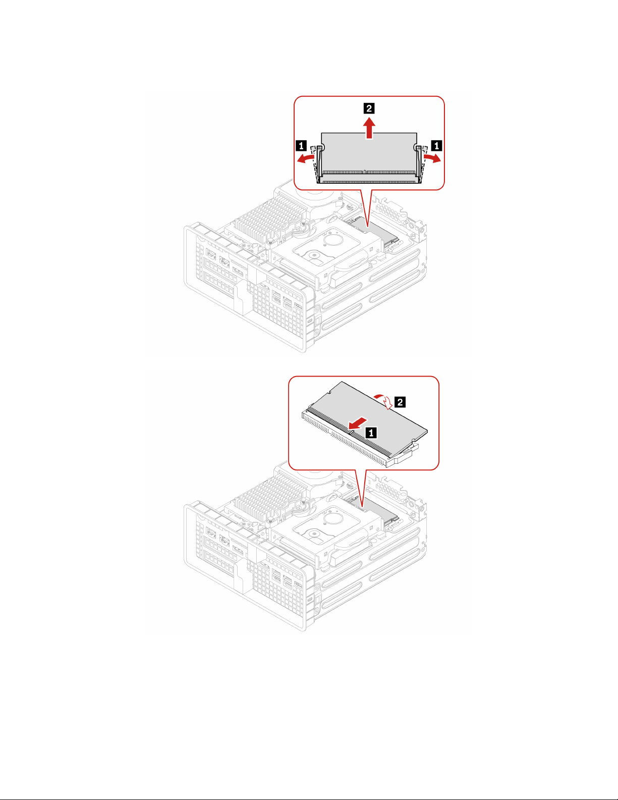
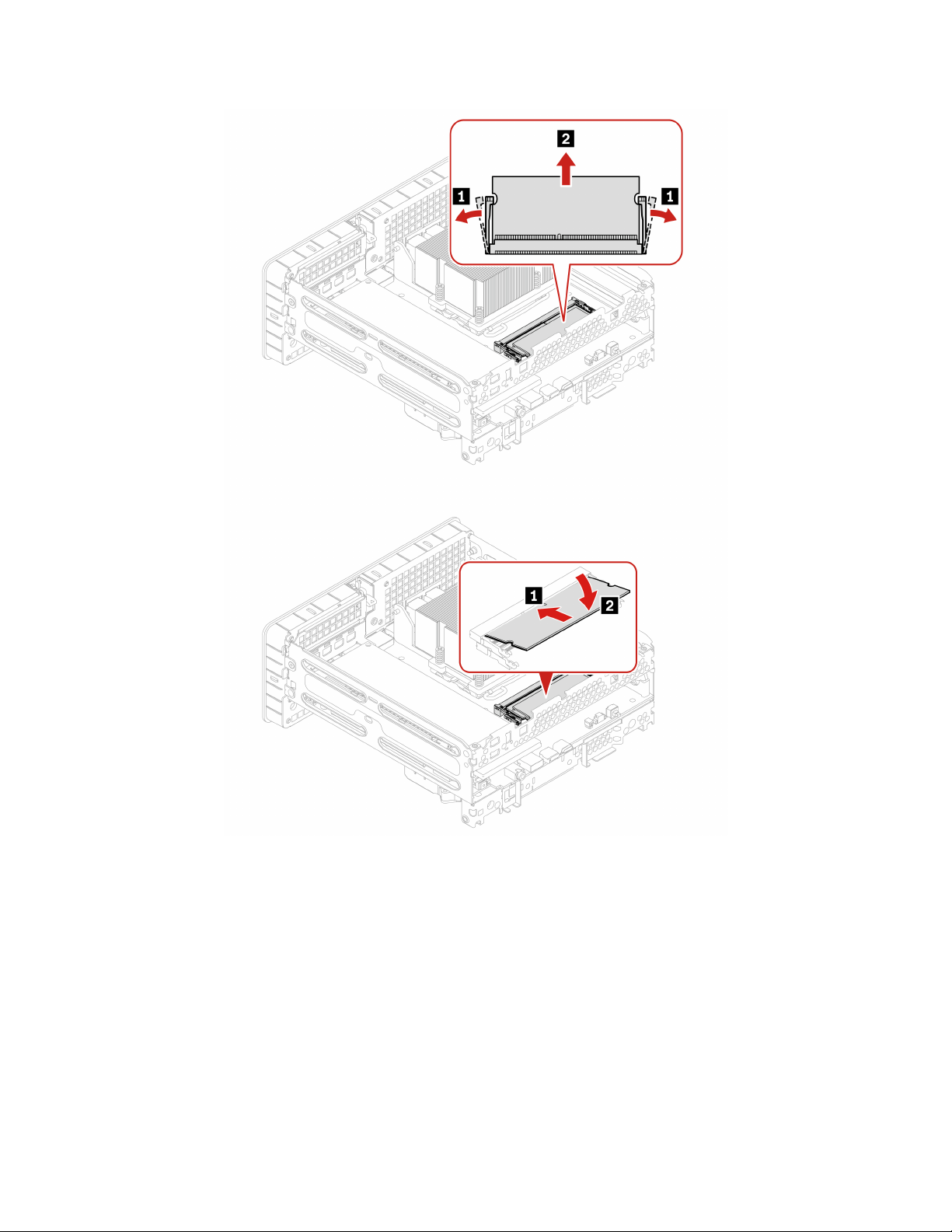
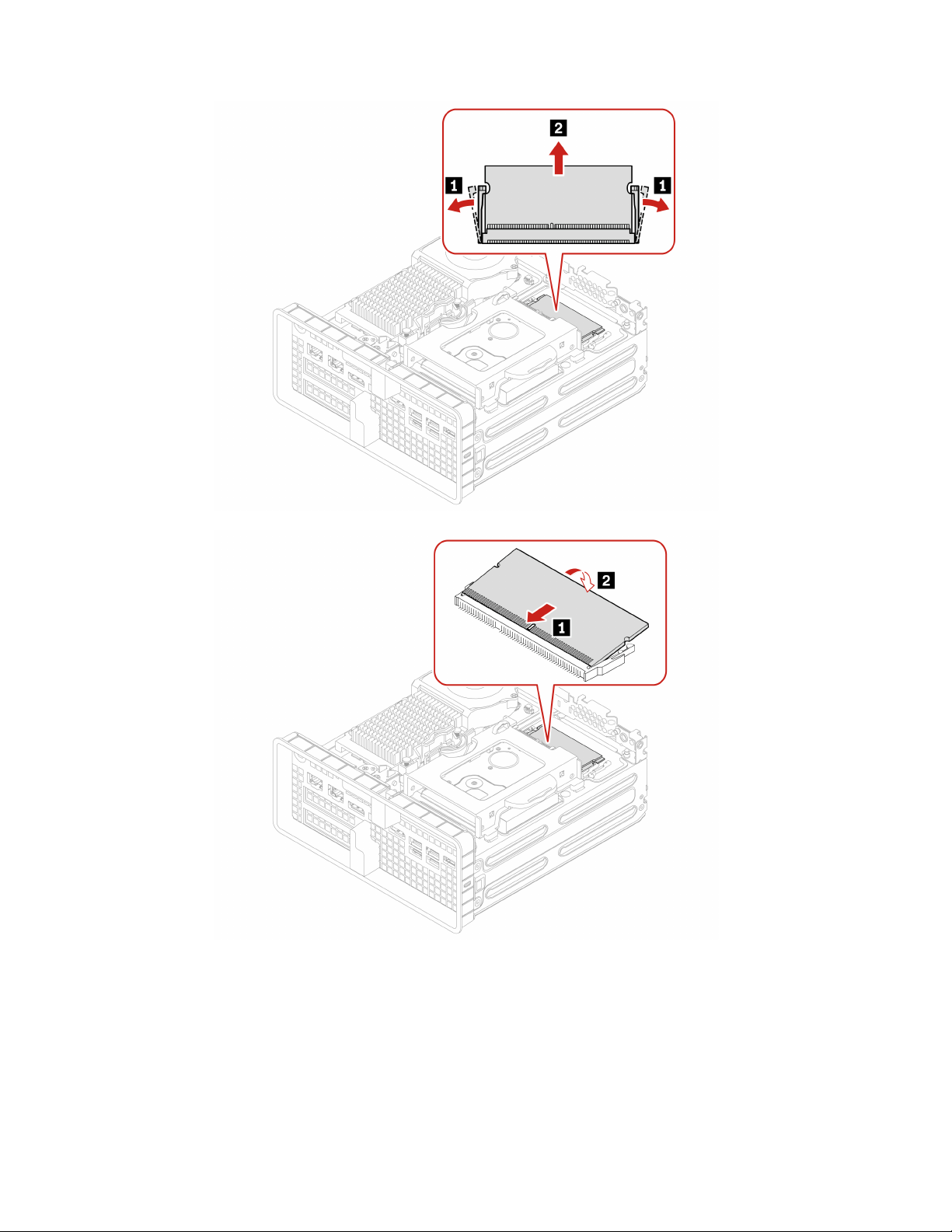
Memory module . . . . . . . . . . . . . 32
PCI-Express card . . . . . . . . . . . . 36
Chapter 8. Help and support . . . . . 41
Self-help resources . . . . . . . . . . . . . 41
Lenovo diagnostic tools . . . . . . . . . . . 41
Call Lenovo . . . . . . . . . . . . . . . . 42
Before you contact Lenovo . . . . . . . . 42
Lenovo Customer Support Center . . . . . . 42
Purchase additional services. . . . . . . . . . 43
Appendix A. System memory
speed. . . . . . . . . . . . . . . . . . 45
Appendix B. Supplemental
information about the Ubuntu operating
system . . . . . . . . . . . . . . . . . 47
Appendix C. Compliance
information . . . . . . . . . . . . . . . 49
Appendix D. Notices and
trademarks . . . . . . . . . . . . . . . 51
© Copyright Lenovo 2022 i

ii P360 Ultra User Guide

Discover your Lenovo computer
Thank you for choosing a Lenovo computer! We are dedicated to delivering the best solution to you.
Before starting your tour, please read the following information:
• Illustrations in this documentation might look different from your product.
• Depending on the model, some optional accessories, features, software programs, and user interface
instructions might not be applicable to your computer.
• Documentation content is subject to change without notice. To get the latest documentation, go to
https://
pcsupport.lenovo.com
.
© Copyright Lenovo 2022 iii

iv P360 Ultra User Guide
Chapter 1. Meet your computer
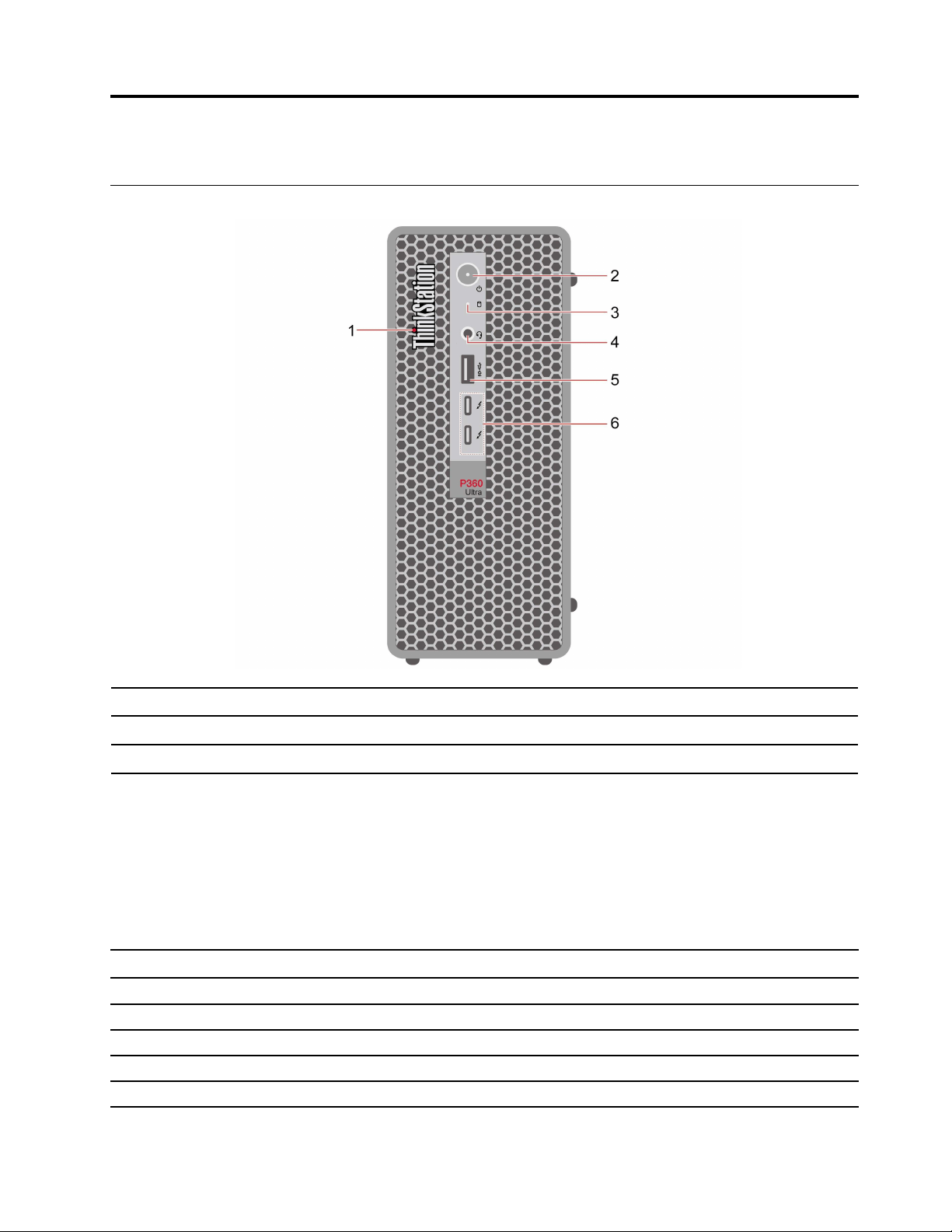
Front
1. ThinkStation® LED
2. Power button with power indicator
3. Storage drive activity indicator
4. Headset audio connector
5. USB 3.2 connector Gen 2
* for selected models
Statement on USB transfer rate
Depending on many factors such as the processing capability of the host and peripheral devices, file
attributes, and other factors related to system configuration and operating environments, the actual transfer
rate using the various USB connectors on this device will vary and will be slower than the data rate listed
below for each corresponding
6. USB-C (Thunderbolt™ 4) connector
device.
USB device Data rate (Gbit/s)
3.2 Gen 1
5
3.2 Gen 2
10
3.2 Gen 2 × 2
20
Thunderbolt 3 40
Thunderbolt 4 40
© Copyright Lenovo 2022 1

Power indicator
Show the system status of your computer.
• Blinking for three times: The computer is initially connected to power.
• On: The computer is starting up or working.
• Off: The computer is off or in hibernation mode.
• Blinking rapidly: The computer is entering sleep or hibernation mode.
• Blinking slowly: The computer is in sleep mode.
Headset connector
The headset connector is compatible with:
• Headphones or earphones with a 3.5mm (0.14 inch), TRS (3-pole) plug
• Headsets with a 3.5mm (0.14 inch), CTIA-compliant TRRS (4-pole) plug
Note: This headset connector does not support standalone external microphones with a TRS (3-pole) plug
or headsets with an OMTP-compliant TRRS (4-pole) plug.
Related topics
• “USB specifications” on page 6.
2
P360 Ultra User Guide
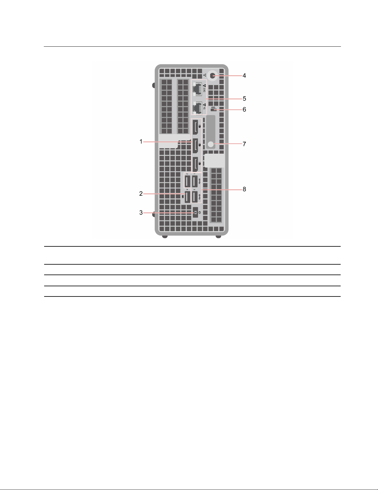
Rear
1. DisplayPort
™
out connectors
2. USB 3.2 connector Gen 2 (with smart power-on
feature)
3. Power cord connector 4. Wi-Fi® antenna slot
5. Ethernet connectors
6. Security-lock slot
7. Chassis latch 8. USB 3.2 connectors Gen 2
* for selected models
Optional connector
Depending on the computer model, the connector might be a DisplayPort out connector, or a USB-C
connector.
Always On USB 3.2 connector Gen 2
With the Always On USB feature enabled, the Always On USB 3.2 connector Gen 2 can charge a USB-
compatible device when the computer is on, off, in sleep mode, or in hibernation mode.
To enable the Always On USB feature, do the following:
1. Enter the UEFI BIOS menu. See “Enter the BIOS menu” on page 15.
2. Click Devices ➙ USB Setup ➙ Front USB Ports ➙ USB Port 2 to enable the Always On USB feature.
Related topics
• “USB specifications” on page 6.
• “Lock the computer” on page 11.
Chapter 1. Meet your computer 3

4 P360 Ultra User Guide

Features and specifications
For detailed specifications of your computer, go to
https://psref.lenovo.com.
Dimensions
• Width: 87 mm (3.43 inches)
• Height: 202 mm (7.95 inches)
• Depth: 223 mm (8.78 inches)
Weight (without packaging) Maximum configuration as shipped: 3.6 kg (7.94 lb)
Hardware configuration
1. Open the system menu from the top-right corner and click Settings.
2. Click About.
Power supply
• 170-watt automatic voltage-sensing power supply
• 230-watt automatic voltage-sensing power supply
• 300-watt automatic voltage-sensing power supply
Electrical input
• Input voltage: From 100 V ac to 240 V ac
• Input frequency: 50/60 Hz
Adaptability for power supply
• Mainland China: 220 V±22 V, 50 Hz±1 Hz
• Adaptive voltage positioning: 90 V to 264 V, 50/60 Hz
• With voltage selection switch: 90 V to 264 V, 50 Hz±1 Hz
Microprocessor
To view the microprocessor information of your computer, enter Settings and
click About.
Memory
Up to four double data rate 5 (DDR5) small outline dual in-line memory module
(SODIMM)
Maximum memory capacity: 128GB
Storage device
• 2.5-inch form factor height hard disk drive*
• Up to two M.2 solid-state drives*
To view the storage drive capacity of your computer, use the Disks application.
Note: The storage drive capacity indicated by the system is less than the nominal
capacity.
Video features
• The integrated graphics card supports the DisplayPort out connector.
• The optional discrete graphics card provides an enhanced video experience
and extended capabilities.
Expansion
• PCI Express slots
Network features
• Bluetooth*
• Ethernet LAN
• Wireless LAN*
* for selected models
Chapter 1. Meet your computer 5
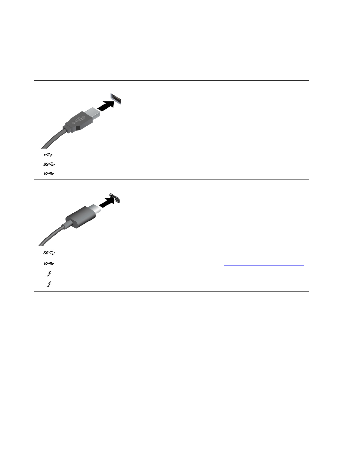
USB specifications
Note: Depending on the model, some USB connectors might not be available on your computer.
Connector name
Description
• USB 2.0 connector
•
USB 3.2 connector Gen 1
•
USB 3.2 connector Gen 2
Connect USB-compatible devices, such as a USB
keyboard, USB mouse, USB storage device, or USB
printer.
• USB-C (3.2 Gen 1) connector
•
USB-C (3.2 Gen 2) connector
•
USB-C (Thunderbolt 3) connector
•
USB-C (Thunderbolt 4) connector
• Charge USB-C compatible devices with the output
voltage and current of 5 V and 3 A.
• Connect to an external display:
– USB-C to VGA: 1920 x 1200 pixels, 60 Hz
– USB-C to DP: 3840 x 2160 pixels, 60 Hz
• Connect to USB-C accessories to help expand your
computer functionality. To purchase USB-C
accessories, go to
https://www.lenovo.com/accessories.
6 P360 Ultra User Guide
Chapter 2. Get started with your computer
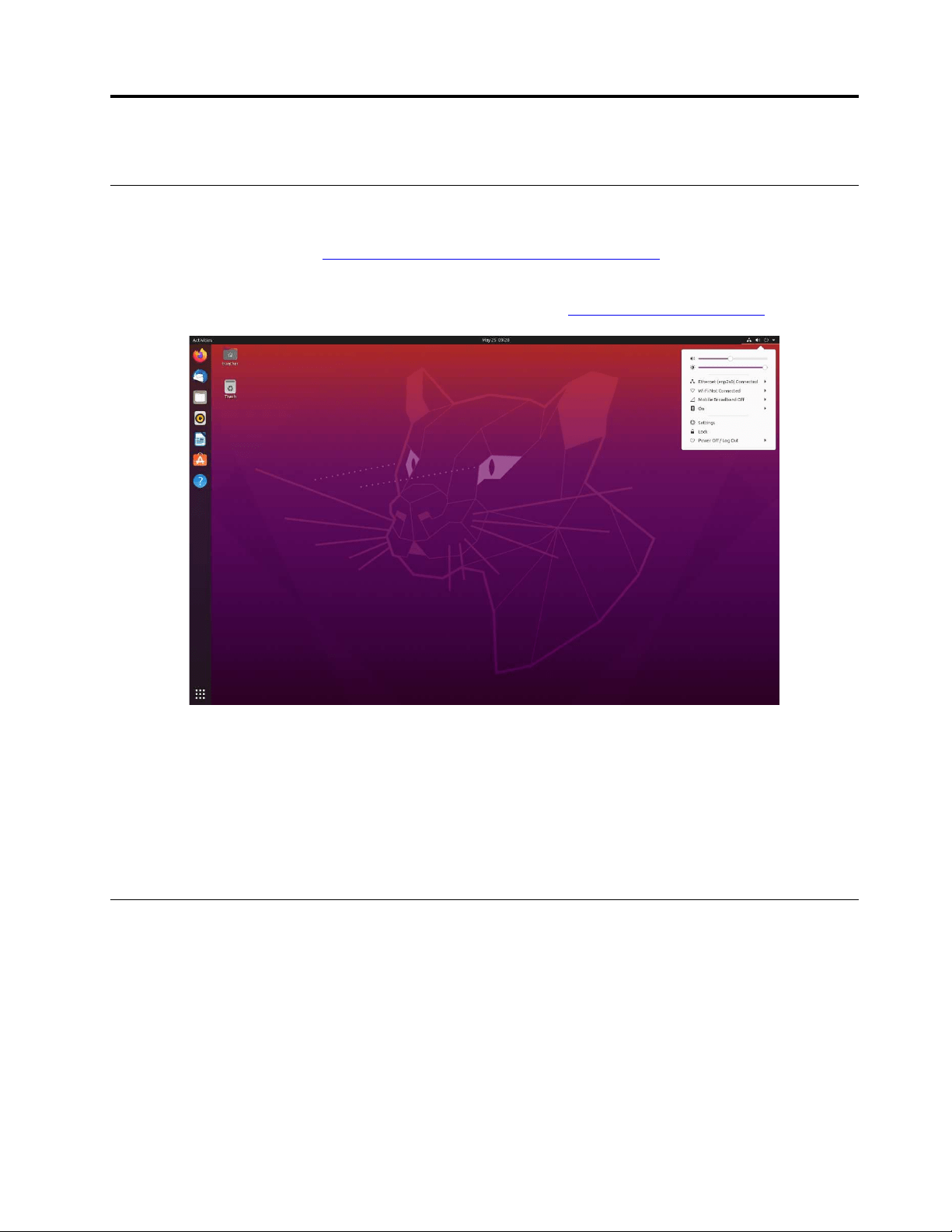
Get started with Ubuntu Desktop
Learn the basics of Ubuntu and start working with it right away. For more information about Ubuntu, see the
Ubuntu documentation site at:
https://help.ubuntu.com/lts/ubuntu-help/index.html.
The Gnome desktop is installed by default and is designed to be simple and easy to use. Details on using
Gnome are available by launching the Help application or online at
https://help.gnome.org/users/.
Launch an app
• Press the Super key (with the Windows logo) or open the Activities menu on the top left and type in the
name of the application you want to launch.
• Click the Show Applications button on the lower left, and select the application you want to launch.
Launch settings
Open the system menu from the top-right corner and click Settings.
Access networks
This section helps you access networks through connecting to a wired or wireless network.
Connect to the wired Ethernet
Connect your computer to a local network through the Ethernet connector on your computer with an
Ethernet cable.
Connect to Wi-Fi networks (for selected models)
If your computer includes a wireless LAN module, you can connect your computer to Wi-Fi
®
networks.
© Copyright Lenovo 2022 7
1. Open the system menu from the top-right corner and expand the Wi-Fi section of the menu.
2. Click Select Network. A list of available wireless networks is displayed.
3. Select a network available for connection. Provide required information, if needed.
Connect an external display
Connect a projector or a monitor to your computer to give presentations or expand your workspace.
Change display settings
Right-click a blank area on the desktop and select Display settings. Then, you can change display settings
as you prefer.
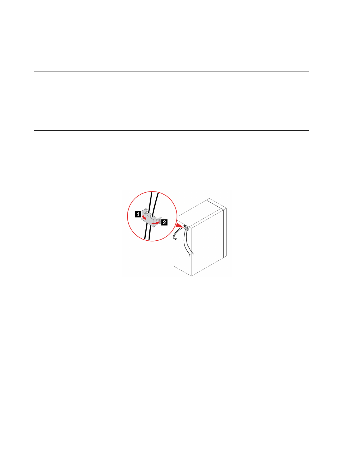
Manage cables with a smart cable clip
Note: You can purchase a smart cable clip from Lenovo.
To manage cables of devices (such as the keyboard and the mouse) with a smart cable clip:
1. Pull the cables through the dents in the clip.
2. Install the clip as shown.
8 P360 Ultra User Guide
Chapter 3. Explore your computer
Set the power plan
For ENERGY STAR
®
compliant computers, the following power plan takes effect when your computers have
been idle for a specified duration:
• turn off the display: After 5 minutes
• put the computer to sleep: After 20 minutes
To awaken the computer from Sleep mode, press any key on your keyboard.
To reset the power plan to achieve the best balance between performance and power saving:
1. Open the system menu from the top-right corner and click Settings.
2. Click Power.
3. Choose or customize a power plan of your preference.
Transfer data
Quickly share your files using the built-in Bluetooth technology among devices with the same features. You
also can install a disc or media card to transfer data.
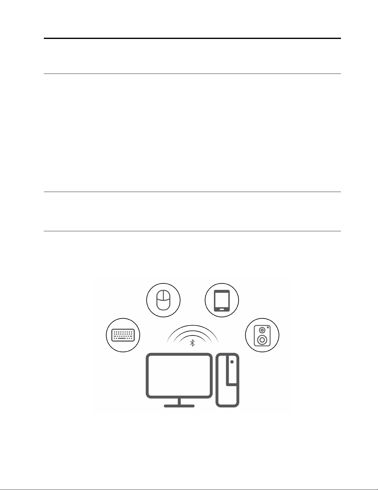
Connect to a Bluetooth-enabled device (for selected models)
You can connect all types of Bluetooth-enabled devices to your computer, such as a keyboard, a mouse, a
smartphone, or speakers. Place the device that you are attempting to connect to less than 10 meters (33
feet) from the computer.
1. Turn on Bluetooth on the computer.
a. Open the system menu from the top-right corner and then click Settings ➙ Bluetooth.
b. In the Bluetooth section enable Bluetooth with the toggle button at the top.
© Copyright Lenovo 2022 9

2. Any discoverable devices will be shown in the Devices list.
3. Select a Bluetooth device, and then follow the on-screen instructions.
Purchase accessories
Lenovo has a number of hardware accessories and upgrades to help expand the capabilities of your
computer. Options include memory modules, storage devices, network cards, power adapters, keyboards,
mice, and more.
To shop at Lenovo, go to
https://www.lenovo.com/accessories.
10
P360 Ultra User Guide
Chapter 4. Secure your computer and information
Lock the computer
Note: Lenovo makes no comments, judgments, or warranties about the function, quality, or performance of
the locking device and security feature. You can purchase computer locks from Lenovo.
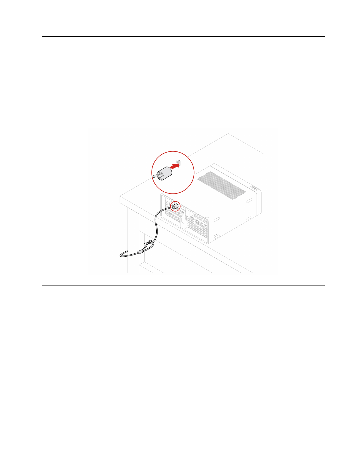
Kensington-style cable lock
Lock your computer to a desk, table, or other fixtures through a Kensington-style cable lock.
UEFI BIOS passwords
You can set passwords in UEFI (Unified Extensible Firmware Interface) BIOS (Basic Input/Output System) to
strengthen the security of your computer.
Password types
You can set a power-on password, supervisor password, system management password, or hard disk
password in UEFI BIOS to prevent unauthorized access to your computer. However, you are not prompted to
enter any UEFI BIOS password when your computer resumes from sleep mode.
• Power-on password
When a power-on password is set, you are prompted to enter a valid password each time the computer is
turned on.
• Supervisor password
Setting a supervisor password deters unauthorized users from changing configuration settings. If you are
responsible for maintaining the configuration settings of several computers, you might want to set a
supervisor password.
When a supervisor password is set, you are prompted to enter a valid password each time you try to enter
the BIOS menu.
© Copyright Lenovo 2022 11

If both the power-on password and supervisor password are set, you can enter either password.
However, you must use your supervisor password to change any configuration settings.
• Hard disk password
Setting a hard disk password prevents unauthorized access to the data on the storage drive. When a hard
disk password is set, you are prompted to enter a valid password each time you try to access the storage
drive.
Note: After you set a hard disk password, your data on the storage drive is protected even if the storage
drive is removed from one computer and installed in another.
• System management password (for selected models)
You can enable the system management password to have the same authority as the supervisor
password to control security related features. To customize the authority of the system management
password through the UEFI BIOS menu:
1. Restart the computer. When the logo screen is displayed, press F1 or Fn+F1.
2. Select Security ➙ System Management Password Access Control.
3. Follow the on-screen instructions.
If you have set both the supervisor password and the system management password, the supervisor
password overrides the system management password.
Set, change, and remove a password
Before you start, print these instructions.
1. Restart the computer. When the logo screen is displayed, press F1 or Fn+F1.
2. Select Security.
3. Depending on the password type, select Set Supervisor Password, Set Power-On Password, Set
System Management Password, or Hard Disk Password and press Enter.
4. Follow the on-screen instructions to set, change, or remove a password.
5. Press F10 or Fn+F10 to save the changes and exit.
You should record your passwords and store them in a safe place. If you forget the passwords, contact a
Lenovo-authorized service provider to have the passwords removed.
Note: If the hard disk password is forgotten, Lenovo cannot remove the password or recover data from the
storage drive.
Certificate based BIOS management
Certificate-based BIOS authentication (also called the password-less management mode) provides more
secure UEFI BIOS management with password-free solution. It is used to replace the supervisor password /
system management password for authentication if you have set one.
Note: Supervisor password / system management password are disabled automatically when certificate
mode is enabled. But the power-on password / hard disk password still can be used normally in certificate
mode if you have set one.
For certificate enrollment, see Certificate Enrollment Guide at:
https://support.lenovo.com/docs/certificate_
enrollment_guide
Enter the BIOS menu with certificate
Once you have enrolled the certificate, you can enter the BIOS menu with the certificate.
1. Restart the computer. When the logo screen is displayed, press F1 or Fn+F1 to enter the BIOS menu.
12
P360 Ultra User Guide

2. The request data is displayed. Click Save to File to save the request data in a USB key and send the
request data to IT admin by e-mail or phone.
3. Enter the unlock code provided by IT admin and click OK.
Notes:
• The unlock encode is a one-time password and is valid only during logon prompt (in one power-on cycle)
for up to two hours.
• If you click Skip, you can enter the BIOS setup menu without BIOS management authority. But certificate
reset is allowed.
Reset certificate
The enrolled certificate cannot be disabled. You can reset or remove it:
1. Restart the computer. When the logo screen is displayed, press F1 or Fn+F1.
2. Enter the BIOS menu with the certificate or skip the certification authentication process.
3. Select Security ➙ Reset Certificate.
4. Follow the on-screen instructions to enter the reset code provided by IT admin.
Computrace Agent software embedded in firmware (for selected
models)
The Computrace Agent software is an IT asset management and computer theft recovery solution. The
software detects if changes have been made on the computer, such as hardware, software, or the computer
call-in location. You might have to purchase a subscription to activate the Computrace Agent software.
Use BIOS security solutions
This section provides BIOS solutions to secure your computer and information.
Wipe the storage drive data
It is recommended that you wipe the storage drive data before recycling the storage drive or the computer.
To wipe the storage drive data:
1. Restart the computer. When the logo screen is displayed, press F1 or Fn+F1.
2. Select Security ➙ secure wipe ➙ Enabled.
3. Press F10 or Fn+F10 to save the changes and exit.
4. Restart the computer. When the logo screen is displayed, press F12 or Fn+F12.
5. Select App Menu ➙ secure wipe and press Enter.
6. Select the storage drive you will wipe and click NEXT.
7. Select the entire storage drive or partition to wipe as desired.
8. Select the method as desired and click NEXT.
9. Click Yes to confirm your option when the prompting window is displayed.
10. If you have set a hard disk password for the storage drive, enter the password. Otherwise, set a
temporary password following the on-screen instructions. Then, click NEXT. The wiping process begins.
Note: Duration of the wiping process varies depending on the storage drive capacity.
11. Click Reboot when you are prompted to reset the system, and then one of the following will happen:
• If the system storage drive data is wiped, you will be prompted that no operating system is found.
Chapter 4. Secure your computer and information 13

• If the non-system storage drive data is wiped, the computer restarts automatically.
Cover presence switch
The cover presence switch prevents the computer from logging in to the operating system when the
computer cover is not properly installed or closed.
To enable the cover presence switch connector on the system board:
1. Restart the computer. When the logo screen is displayed, press F1 or Fn+F1.
2. Select Security ➙ Cover Tamper Detected and press Enter.
3. Select Enabled and press Enter.
4. Press F10 or Fn+F10 to save the changes and exit.
If the cover presence switch is enabled and the computer cover is not correctly installed or closed, an error
message will be displayed when you turn on the computer. To bypass the error message and log in to the
operating system:
1. Properly install or close the computer cover.
2. Enter the BIOS menu, save and then exit.
Intel BIOS guard
The Intel BIOS Guard module cryptographically verifies all BIOS updates. This hardware-based security
helps prevent software and malware attacks on the computers BIOS.
Smart USB Protection
The Smart USB Protection function is a security function that helps prevent data from being copied from the
computer to USB storage devices connected to the computer. You can set the Smart USB Protection
function to one of the following modes:
• Disabled (default setting): You can use the USB storage devices without limitation.
• Read Only: You cannot copy data from the computer to the USB storage devices. However, you can
access or modify data on the USB storage devices.
• No Access: You cannot access the USB storage devices from the computer.
To configure the Smart USB Protection function:
1. Restart the computer. When the logo screen is displayed, press F1 or Fn+F1.
2. Select Security ➙ Smart USB Protection and press Enter.
3. Select the desired setting and press Enter.
4. Press F10 or Fn+F10 to save the changes and exit.
14
P360 Ultra User Guide

Chapter 5. UEFI BIOS
This chapter provides information about configuring and updating UEFI BIOS, and clearing CMOS.
What is UEFI BIOS
Note: The operating system settings might override any similar settings in UEFI BIOS.
UEFI BIOS is the first program that the computer runs when the computer is turned on. UEFI BIOS initializes
the hardware components and loads the operating system and other programs. Your computer comes with a
setup program with which you can change UEFI BIOS settings.
Enter the BIOS menu
Restart the computer. When the logo screen is displayed, press F1 or Fn+F1 to enter the BIOS menu.
Note: If you have set BIOS passwords, enter the correct passwords when prompted. You also can select No
or press Esc to skip the password prompt and enter the BIOS menu. However, you cannot change the
system configurations that are protected by passwords.
Navigate in the BIOS interface
Attention: The default configurations are already optimized for you in boldface. Improper change of the
configurations might cause unexpected results.
Depending on your keyboard, you can navigate in the BIOS interface by pressing the following keys, or
combinations of Fn and the following keys:
Key Function
F1 or Fn+F1 General Help
Esc or Fn+Esc Exit the submenu
↑↓ or Fn+↑↓ Locate an item
← → or Fn+← → Move keyboard focus
+/– or Fn++/– Change value
Enter Enter the submenu
F9 or Fn+F9
Setup Defaults
F10 or Fn+F10 Save and exit
Change the display language of UEFI BIOS
UEFI BIOS supports three or four display languages: English, French, simplified Chinese, and Russian (for
selected models).
To change the display language of UEFI BIOS:
1. Select Main ➙ Language and press Enter.
2. Set the display language as desired.
© Copyright Lenovo 2022 15

Change the display mode of UEFI BIOS (for selected models)
You can use UEFI BIOS in the graphic mode or the text mode according to your needs.
The keys on the keyboard used to perform various tasks are displayed at the bottom of the screen. In
addition to the keyboard, you also can use the mouse to make selections.
To change the display mode of UEFI BIOS:
1. Restart the computer. When the logo screen is displayed, press F1 or Fn+F1.
2. Select Main ➙ Setup Mode Select and press Enter.
3. Set the display mode as desired.
Set the system date and time
1. Restart the computer. When the logo screen is displayed, press F1 or Fn+F1.
2. Select Main ➙ System Time & Date and press Enter.
3. Set the system date and time as desired.
4. Press F10 or Fn+F10 to save the changes and exit.
Change the boot priority order
If the computer does not boot from a device as expected, you can change the boot priority order
permanently or select a temporary boot device.
Change the boot priority order permanently
1. Depending on the type of the storage device, do one of the following:
• If the storage device is internal, go to step 2.
• If the storage device is a disc, ensure that the computer is on or turn on the computer. Then, insert
the disc into the optical drive.
• If the storage device is an external device other than a disc, connect the storage device to the
computer.
2. Restart the computer. When the logo screen is displayed, press F1 or Fn+F1.
3. Select Startup ➙ Boot Priority Order, and then follow the on-screen instructions to change the boot
priority order.
4. You can also select the first priority device group by selecting Startup ➙ First Boot Device, and then
follow the on-screen instructions to select the first boot device within this group. Your computer will
boot from the first boot device before trying the boot priority order you set in the previous step.
5. Press F10 or Fn+F10 to save the changes and exit.
Select a temporary boot device
Note: Not all discs and storage drives are bootable.
1. Depending on the type of the storage device, do one of the following:
• If the storage device is internal, go to step 2.
• If the storage device is a disc, ensure that the computer is on or turn on the computer. Then, insert
the disc into the optical drive.
• If the storage device is an external device other than a disc, connect the storage device to the
computer.
16
P360 Ultra User Guide

2. Restart the computer. When the logo screen is displayed, press F12 or Fn+F12.
3. Select the storage device as desired and press Enter.
If you want to change the boot priority order permanently, select Enter Setup on Startup Device Menu and
press Enter to enter the BIOS menu.
Enable or disable the configuration change detection feature
If you enable configuration change detection, when the POST detects configuration changes of some
hardware devices (such as storage drives or memory modules), an error message will be displayed when you
turn on the computer.
To enable or disable the configuration change detection feature:
1. Restart the computer. When the logo screen is displayed, press F1 or Fn+F1.
2. Select Security ➙ Configuration Change Detection and press Enter.
3. Enable or disable the feature as desired.
4. Press F10 or Fn+F10 to save the changes and exit.
To bypass the error message and log in to the operating system, press F2 or Fn+F2. To clear the error
message, enter the BIOS menu, save and then exit.
Enable or disable the automatic power-on feature
The Automatic Power On item in UEFI BIOS provides various options for you to make your computer start up
automatically.
To enable or disable the automatic power-on feature:
1. Restart the computer. When the logo screen is displayed, press F1 or Fn+F1.
2. Select Power ➙ Automatic Power On and press Enter.
3. Select the feature as desired and press Enter.
4. Enable or disable the feature as desired.
5. Press F10 or Fn+F10 to save the changes and exit.
Enable or disable the smart power-on feature (for selected models)
Ensure that the keyboard is connected to a USB connector supporting the smart power-on feature. With the
smart power-on feature enabled, you can start up or wake up the computer from the hibernation mode by
pressing Alt+P.
To enable or disable the smart power-on feature:
1. Restart the computer. When the logo screen is displayed, press F1 or Fn+F1.
2. Select Power ➙ Smart Power On and press Enter.
3. Enable or disable the feature as desired.
4. Press F10 or Fn+F10 to save the changes and exit.
Change BIOS settings before installing a new operating system
BIOS settings vary by operating system. Change the BIOS settings before installing a new operating system.
To change the BIOS settings:
Chapter 5. UEFI BIOS 17

1. Restart the computer. When the logo screen is displayed, press F1 or Fn+F1.
2. From the main interface, select Security ➙ Secure Boot and press Enter.
3. Depending on the operating system to be installed, do one of the following:
• To install the Windows 10 (64-bit) and most of Linux operating system, select Enabled for Secure
Boot.
• To install an operating system that does not support secure boot, select Disabled for Secure Boot.
4. Press F10 or Fn+F10 to save the changes and exit.
Update UEFI BIOS
When you install a new program, device driver, or hardware component, you might need to update UEFI
BIOS. You can update the BIOS from your operating system or a flash update disc (supported only on
selected models).
Download and install the latest UEFI BIOS update package by one of the following methods:
• Using the built-in software update service:
Ubuntu software update will check the LVFS site for any firmware updates and notify you when updates
are available.
• From the Lenovo Support Web site:
1. Go to
https://pcsupport.lenovo.com.
2. Download the flash BIOS update driver for the operating system version or the ISO image version
(used to create a flash update disc). Then, download the installation instructions for the flash BIOS
update driver you have downloaded.
3. Print the installation instructions and follow the instructions to update the BIOS.
Recover from a BIOS update failure
1. Remove all media from the drives and turn off all connected devices.
2. Insert the BIOS update disc into the optical drive, and then turn off the computer.
3. Disconnect all power cords from electrical outlets. Then, remove any parts that impede access to the
Clear CMOS /Recovery jumper.
4. Move the jumper from the standard position to the maintenance position.
5. Reconnect the power cords for the computer and the monitor to electrical outlets.
6. Turn on the computer and the monitor. When the computer beeps, the recovery process begins.
7. After the recovery process is completed, the computer will be turned off automatically.
Note: Depending on the computer model, the recovery process will take two to three minutes.
8. Disconnect all power cords from electrical outlets.
9. Move the jumper back to the standard position.
10. Reinstall all the parts that have been removed. Then, reconnect the power cords for the computer and
the monitor to electrical outlets.
11. Turn on the computer and the monitor. When the logo screen is displayed, press F1 or Fn+F1.
12. To prevent data loss, ensure that BIOS settings are restored to an earlier point. For BIOS configurations,
see Chapter 5 “UEFI BIOS” on page 15.
18
P360 Ultra User Guide

Clear CMOS
1. Remove all media from the drives and turn off all connected devices and the computer.
2. Disconnect all power cords from electrical outlets. Then, remove any parts that impede access to the
Clear CMOS /Recovery jumper.
3. Move the jumper from the standard position to the maintenance position.
4. Reconnect the power cords for the computer and the monitor to electrical outlets.
5. Turn on the computer and the monitor. When the computer beeps, wait for approximately 10 seconds.
6. Turn off the computer by holding the power button for approximately four seconds.
7. Disconnect all power cords from electrical outlets.
8. Move the jumper back to the standard position.
9. Reinstall all the parts that have been removed. Then, reconnect the power cords for the computer and
the monitor to electrical outlets.
10. Turn on the computer and the monitor. When the logo screen is displayed, press F1 or Fn+F1.
11. To prevent data loss, ensure that BIOS settings are restored to an earlier point. For BIOS configurations,
see Chapter 5 “UEFI BIOS” on page 15.
Chapter 5. UEFI BIOS 19

20 P360 Ultra User Guide

Chapter 6. RAID
What is RAID
Redundant Array of Independent Disks (RAID) is a technology that provides increased storage functions and
reliability through redundancy. It also can improve data storage reliability and fault tolerance compared with
single-drive storage systems. Data loss resulting from a drive failure can be prevented by reconstructing
missing data from the remaining drives.
When a group of independent physical storage drives is set up to use RAID technology, they are in a RAID
array. This array distributes data across multiple storage drives, but the array appears to the host computer
as one single storage unit. Creating and using RAID arrays provides high performance, such as the expedited
I/O performance, because several drives can be accessed simultaneously.
RAID Level
Your computer must have the minimum number of SATA storage drives installed for the supported level of
RAID below:
• RAID 0: striped disk array
– Consists of at least two SATA storage drives
– Supported strip size: 4 KB, 8 KB, 16 KB, 32 KB, 64 KB, or 128 KB
– Better performance without fault tolerance
• RAID 1: mirrored disk array
– Consists of two SATA storage drives
– Improved reading performance and 100% redundancy
• RAID 5: block-level striped disk array with distributed parity
– Consists of at least three SATA storage drives
– Supported strip size: 16 KB, 32 KB, 64 KB, or 128 KB
– Better performance and fault tolerance
• RAID 10: striped and mirrored disk array
– Consists of at least four SATA storage drives
– Supported strip size: 4 KB, 8 KB, 16 KB, 32 KB, or 64 KB
– Better performance without fault tolerance
– Improved reading performance and 100% redundancy
Configure the system BIOS to enable SATA/NVMe RAID functionality
To enable SATA/NVMe RAID functionality:
1. Restart the computer. When the logo screen is displayed, press F1 or Fn+F1.
2. Select Devices ➙ ATA Drive Setup and press Enter.
3. Select Configure SATA as and press Enter.
4. Select RAID and press Enter.
5. Press F10 or Fn+F10 to save the changes and exit.
© Copyright Lenovo 2022 21

Configure RAID in UEFI mode
This section provides instructions on how to configure RAID in UEFI mode.
Create RAID volumes in UEFI mode
Attention: All the existing data stored on the selected drives will be erased while the RAID volume is being
created.
To create RAID volumes:
1. Restart the computer. When the logo screen is displayed, press F1 or Fn+F1.
2. Select Devices ➙ ATA Drive Setup and press Enter.
3. Select Intel (R) Rapid Storage Technology and press Enter.
4. Select Create RAID Volume and press Enter.
5. Select Name and press Enter. When prompted, type a proper RAID Volume name in the field.
6. Select RAID Level and press Enter. When prompted, select a RAID level in the field.
7. Use the arrow keys and the space key to mark individual physical storage drives to be added in the RAID
volume.
8. Select Strip Size and press Enter. When prompted, select a strip size in the field.
9. Select Capacity and type a volume size in the field.
10. Select Create Volume and press Enter to initiate volume creation.
Delete RAID volumes in UEFI mode
Attention: All the existing data stored on the selected drives will be erased after you delete RAID volumes.
To delete RAID volumes:
1. Restart the computer. When the logo screen is displayed, press F1 or Fn+F1.
2. Select Devices ➙ ATA Drive Setup and press Enter.
3. Select Intel (R) Rapid Storage Technology and press Enter.
4. Select the RAID volume to be deleted and press Enter.
5. Select Delete and press Enter.
6. Select Yes to confirm the deletion of the selected RAID volume. Deleting a RAID volume will reset the
storage drives to non-RAID.
Reset storage drives to non-RAID in UEFI mode
To reset your storage drives to non-RAID:
1. Restart the computer. When the logo screen is displayed, press F1 or Fn+F1.
2. Select Devices ➙ ATA Drive Setup and press Enter.
3. Select Intel (R) Rapid Storage Technology and press Enter.
4. Select the RAID volumes and press Enter to view the detailed information. Select the storage drives you
want to reset to non-RAID and then press Enter.
5. Select Reset to Non-RAID and press Enter.
6. Select Yes to reset the storage drives to non-RAID.
22
P360 Ultra User Guide

Chapter 7. CRU replacement
Customer Replaceable Units (CRUs) are parts that can be upgraded or replaced by the customer. Lenovo
computers contain the following types of CRUs:
• Self-service CRUs: Refer to parts that can be installed or replaced easily by customer themselves or by
trained service technicians at an additional cost.
• Optional-service CRUs: Refer to parts that can be installed or replaced by customers with a greater skill
level. Trained service technicians can also provide service to install or replace the parts under the type of
warranty designated for the customer’s machine.
If you intend on installing the CRU, Lenovo will ship the CRU to you. CRU information and replacement
instructions are shipped with your product and are available from Lenovo at any time upon request. You
might be required to return the defective part that is replaced by the CRU. When return is required: (1) return
instructions, a prepaid shipping label, and a container will be included with the replacement CRU; and (2) you
might be charged for the replacement CRU if Lenovo does not receive the defective CRU within thirty (30)
days of your receipt of the replacement CRU. For full details, see the Lenovo Limited Warranty
documentation at:
https://www.lenovo.com/warranty/llw_02
CRU list
The following is the CRU list of your computer.
Self-service CRUs
• 2.5–inch hard disk drive*
• 2.5–inch hard disk drive bracket*
• ac power adapter
• Chassis
• System fan
• Keyboard*
• Memory module
• Mouse*
• Power cord
Optional-service CRUs
• M.2 solid-state drive*
• M.2 solid-state drive thermal kit*
• PCIe card*
• PCIe converter*
* for selected models
Remove or replace a CRU
This section provides instructions on how to remove or replace a CRU.
© Copyright Lenovo 2022 23
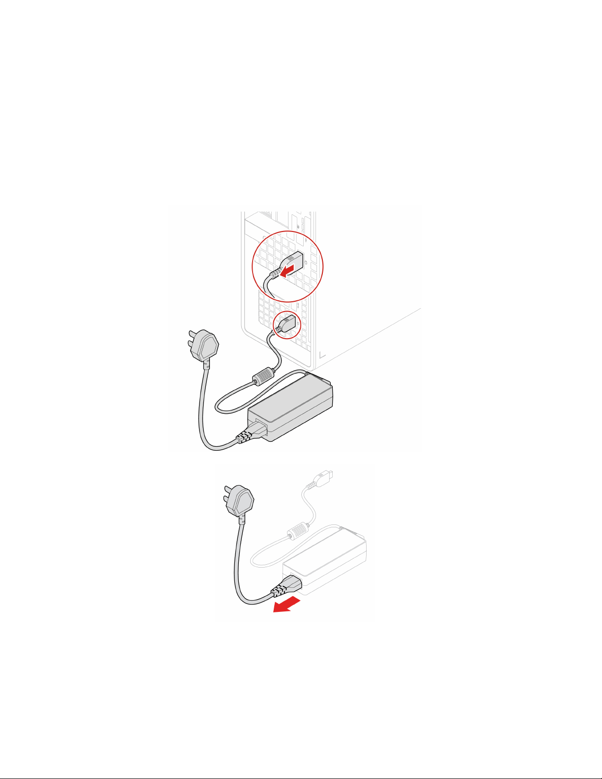
Power adapter and power cord
Prerequisite
Before you start, read Generic Safety and Compliance Notices, and print the following instructions.
For access, do the following:
1. Turn off the computer and remove all connected devices and cables.
2. Disconnect the computer from ac power.
Removal steps
Chassis
Prerequisite
Before you start, read Generic Safety and Compliance Notices, and print the following instructions.
24 P360 Ultra User Guide
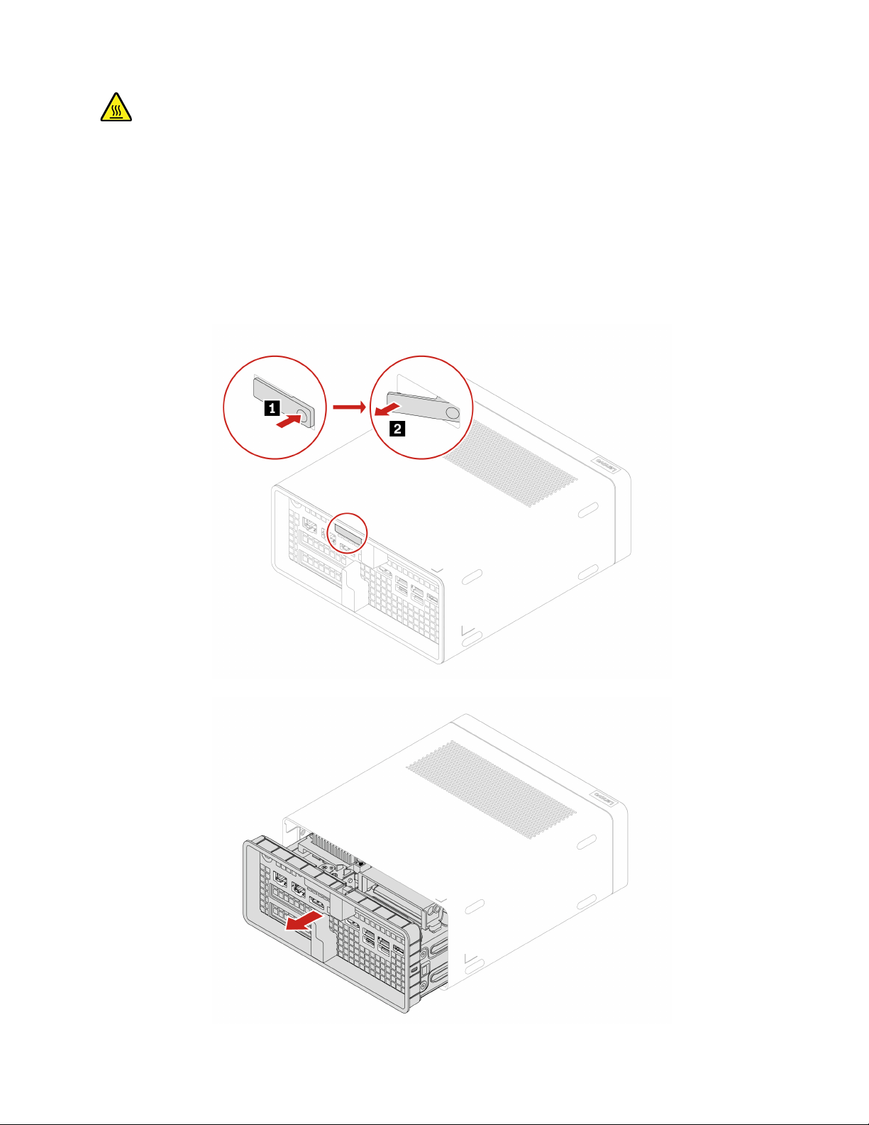
Before you remove the chassis, turn off the computer and wait several minutes until the computer is cool.
For access, do the following:
1. Remove any media from the drives and turn off all connected devices and the computer.
2. Remove power cords from electrical outlets.
3. Disconnect all cables from the computer.
4. Unlock any locking device that secures the computer chassis.
Replacement steps
Chapter 7. CRU replacement 25
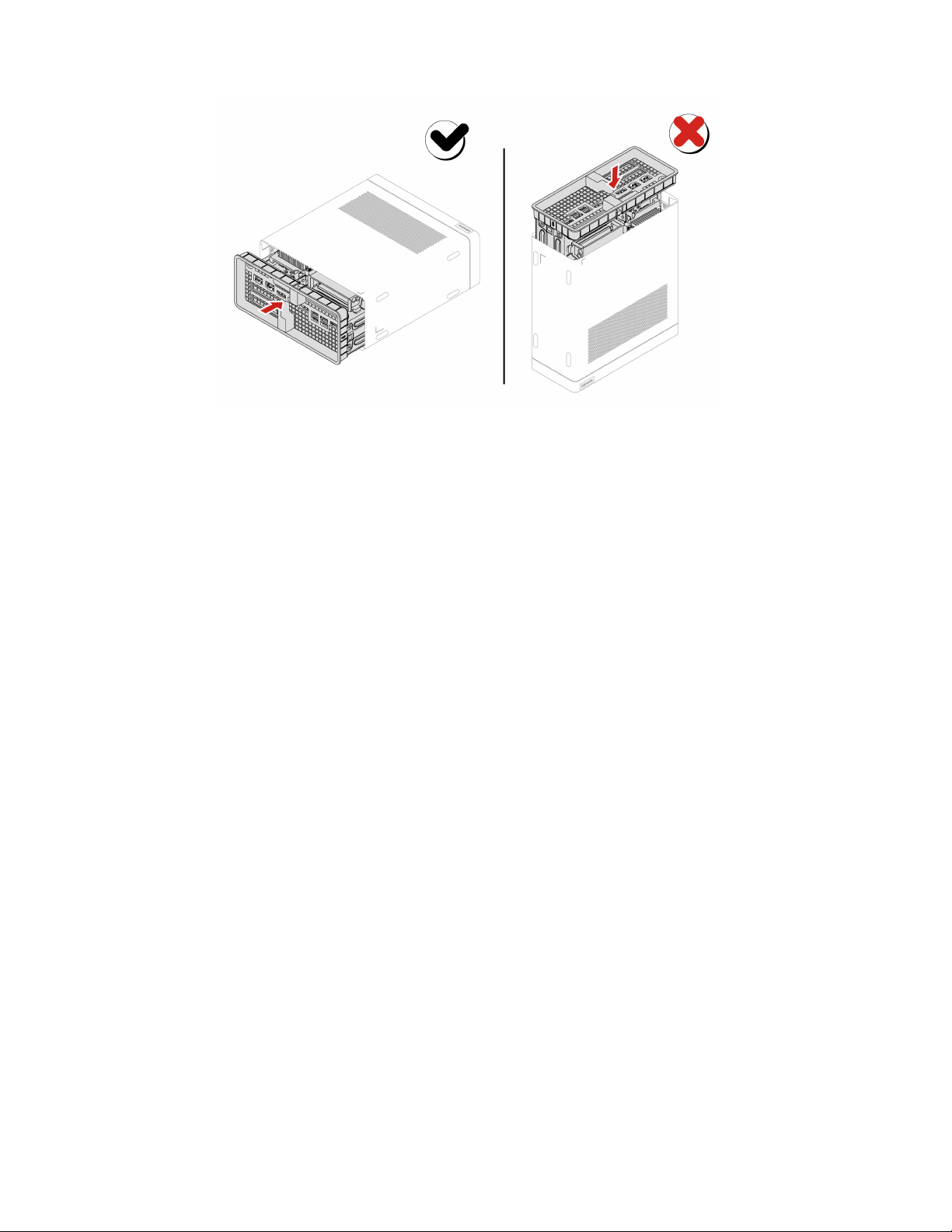
Note: Please push parts into the chassis completely until hear the sound of click.
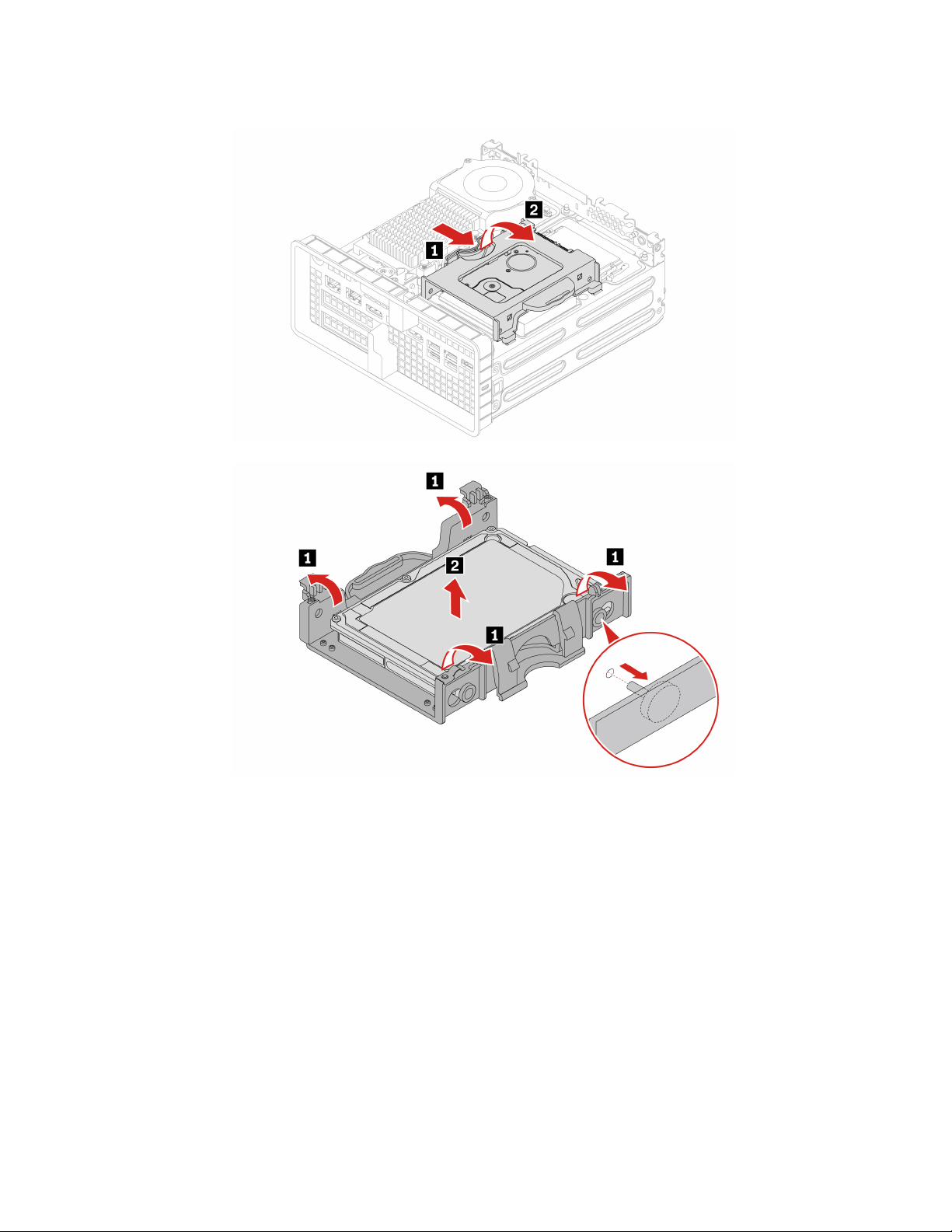
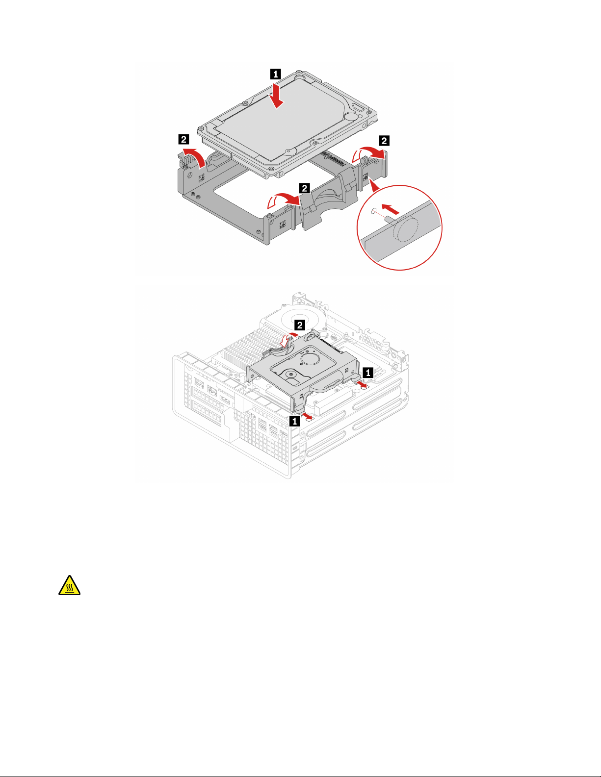
Hard disk drive
Prerequisite
Before you start, read Generic Safety and Compliance Notices, and print the following instructions.
Attention: The internal storage drive is sensitive. Inappropriate handling might cause damage and
permanent loss of data. When handling the internal storage drive, observe the following guidelines:
• Replace the internal storage drive only for upgrade or repair. The internal storage drive is not designed for
frequent changes or replacement.
• Before replacing the internal storage drive, make a backup copy of all the data that you want to keep.
• Do not touch the contact edge of the internal storage drive. Otherwise, the internal storage drive might get
damaged.
• Do not apply pressure to the internal storage drive.
• Do not make the internal storage drive subject to physical shocks or vibration. Put the internal storage
drive on a soft material, such as cloth, to absorb physical shocks.
For access, do the following:
1. Remove the power adapter and cord. See “Power adapter and power cord” on page 24.
2. Remove the chassis. See “Chassis” on page 24.
3. Disconnect the signal cable and the power cable from the storage drive.
26
P360 Ultra User Guide
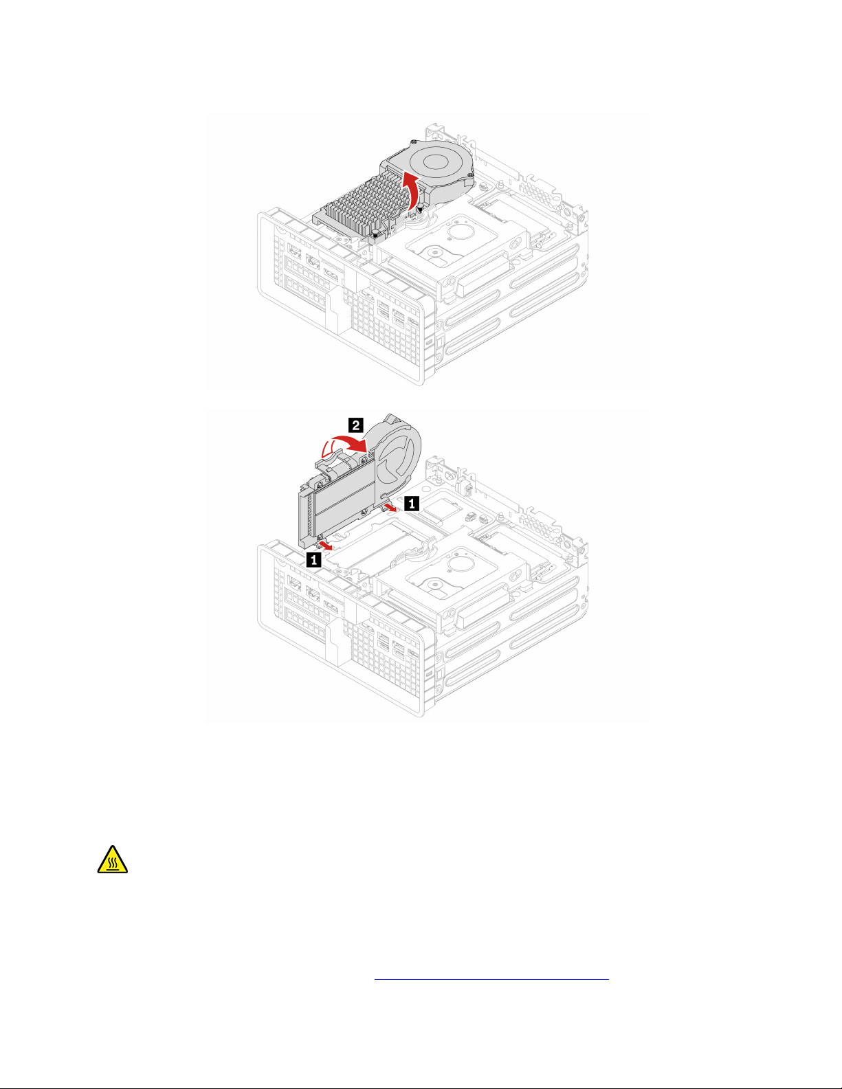
M.2 solid-state drive thermal kit
Prerequisite
Before you start, read Generic Safety and Compliance Notices, and print the following instructions.
The heat sink might be very hot. Before you open the computer cover, turn off the computer and wait several
minutes until the computer is cool.
For access, remove the following parts in order:
• “Power adapter and power cord” on page 24.
• “Chassis” on page 24.
28
P360 Ultra User Guide
Replacement steps
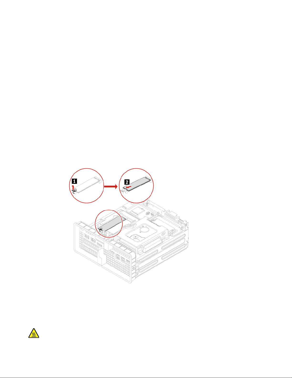
M.2 solid-state drive
Prerequisite
Before you start, read Generic Safety and Compliance Notices, and print the following instructions.
The heat sink might be very hot. Before you open the computer cover, turn off the computer and wait several
minutes until the computer is cool.
Attention:
• To replace the Intel Optane memory, go to
https://support.lenovo.com/docs/tg_ssd.
Chapter 7. CRU replacement 29
• Do not attempt to replace the Intel Optane memory in the M.2 solid-state drive slot. Replacement of the
Intel Optane memory must be done by a Lenovo-authorized repair facility or technician.
• The internal storage drive is sensitive. Inappropriate handling might cause damage and permanent loss of
data. When handling the internal storage drive, observe the following guidelines:
– Replace the internal storage drive only for upgrade or repair. The internal storage drive is not designed
for frequent changes or replacement.
– Before replacing the internal storage drive, make a backup copy of all the data that you want to keep.
– Do not touch the contact edge of the internal storage drive. Otherwise, the internal storage drive might
get damaged.
– Do not apply pressure to the internal storage drive.
– Do not make the internal storage drive subject to physical shocks or vibration. Put the internal storage
drive on a soft material, such as cloth, to absorb physical shocks.
For access, remove these parts in order, if any:
• “Power adapter and power cord” on page 24.
• “Chassis” on page 24.
• “M.2 solid-state drive thermal kit” on page 28.
Removal steps
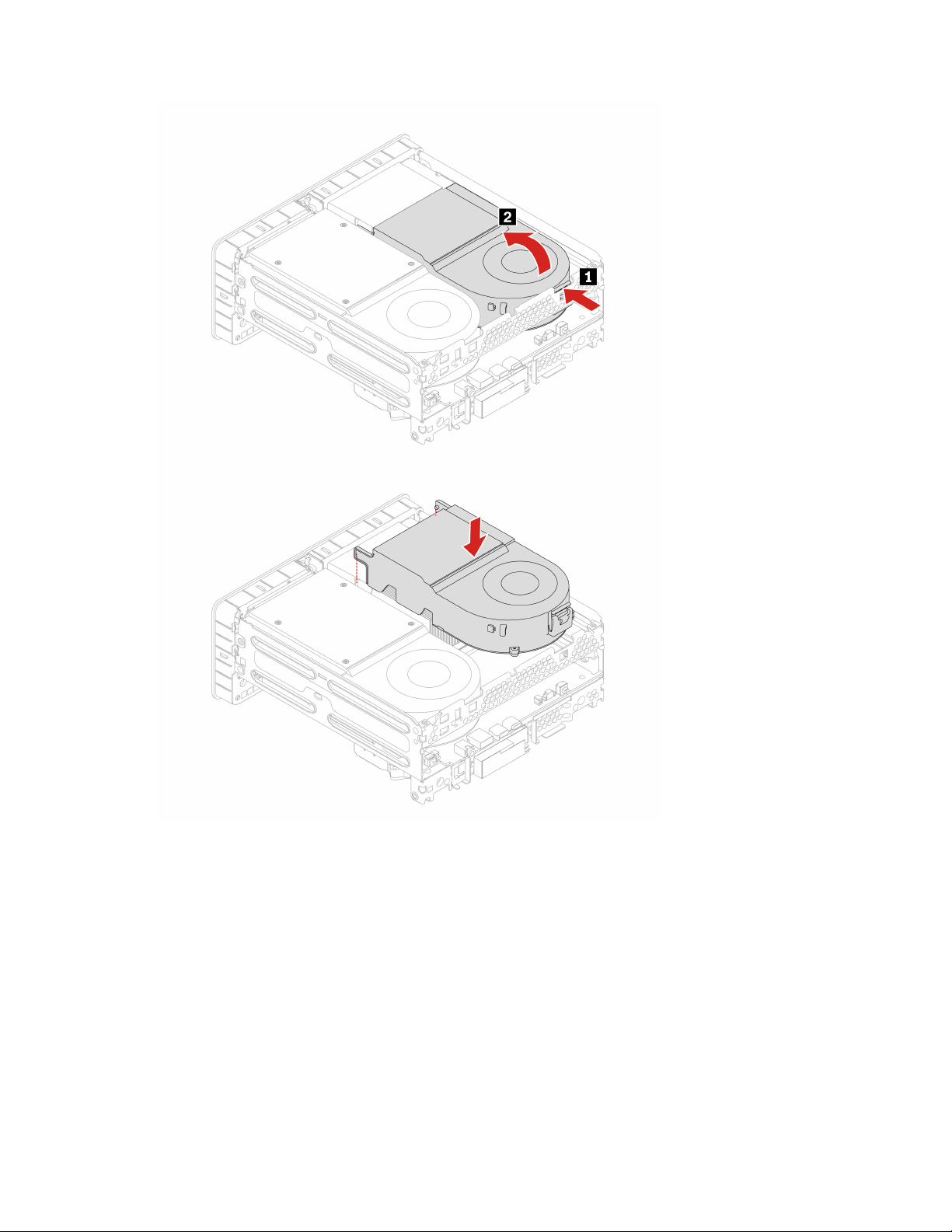
System Fan
Prerequisite
Before you start, read Generic Safety and Compliance Notices, and print the following instructions.
30 P360 Ultra User Guide
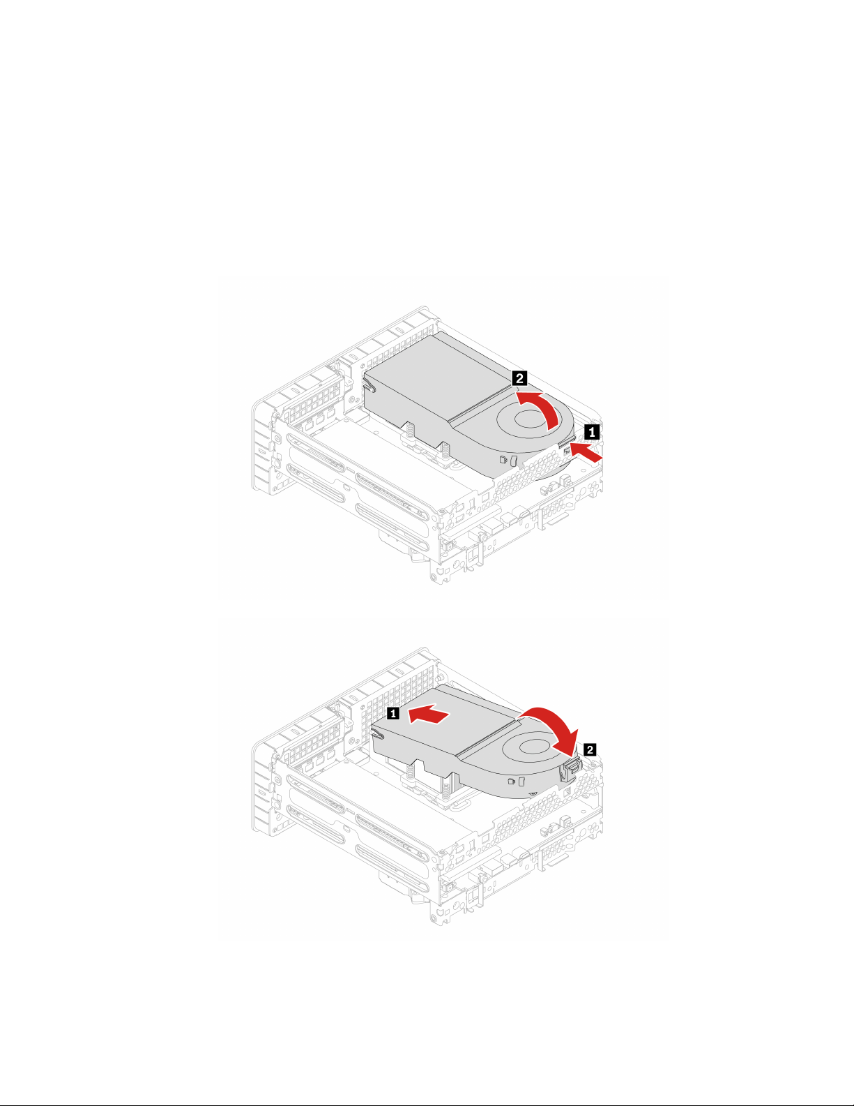
The system Fan might be very hot. Before you open the computer cover, turn off the computer and wait
several minutes until the computer is cool.
For access, do the following:
1. Remove the power adapter and cord. See “Power adapter and power cord” on page 24.
2. Remove the chassis. See “Chassis” on page 24.
Removal steps
• Type 1
Chapter 7. CRU replacement 31
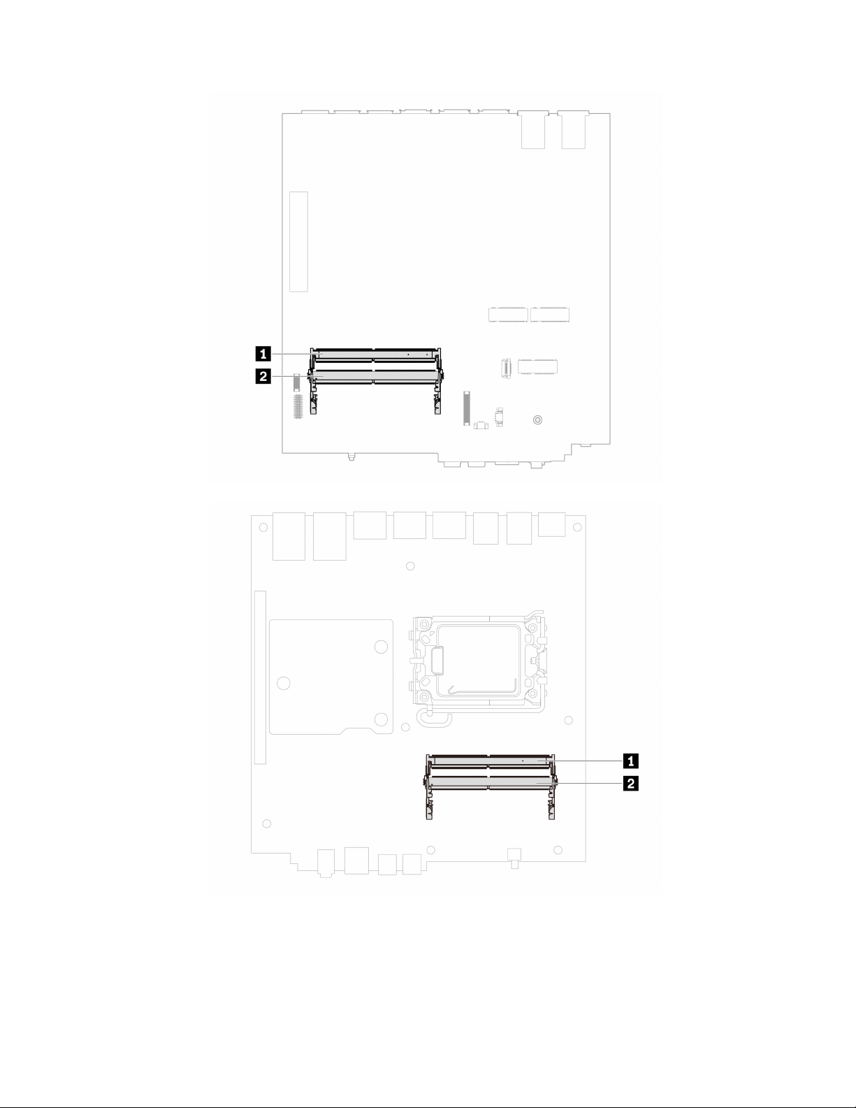
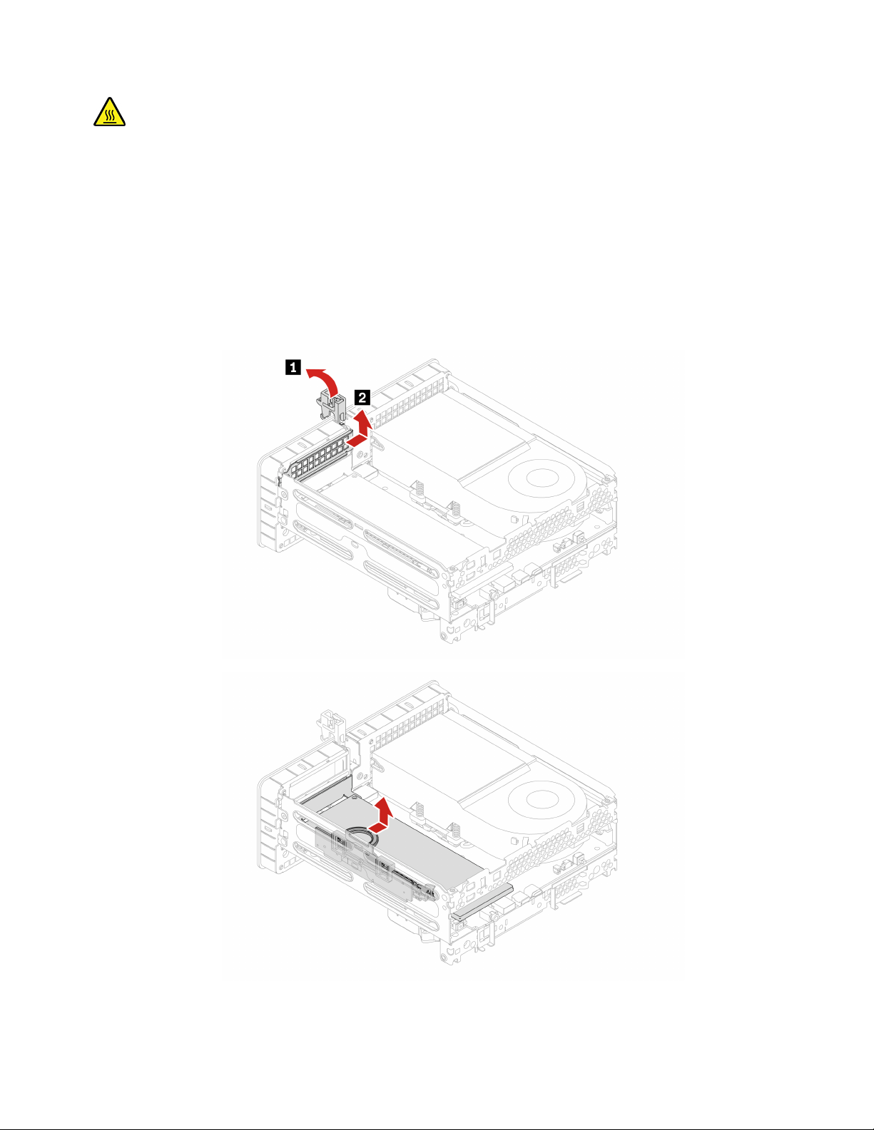
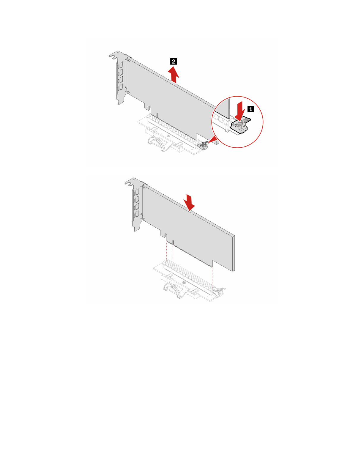
38 P360 Ultra User Guide
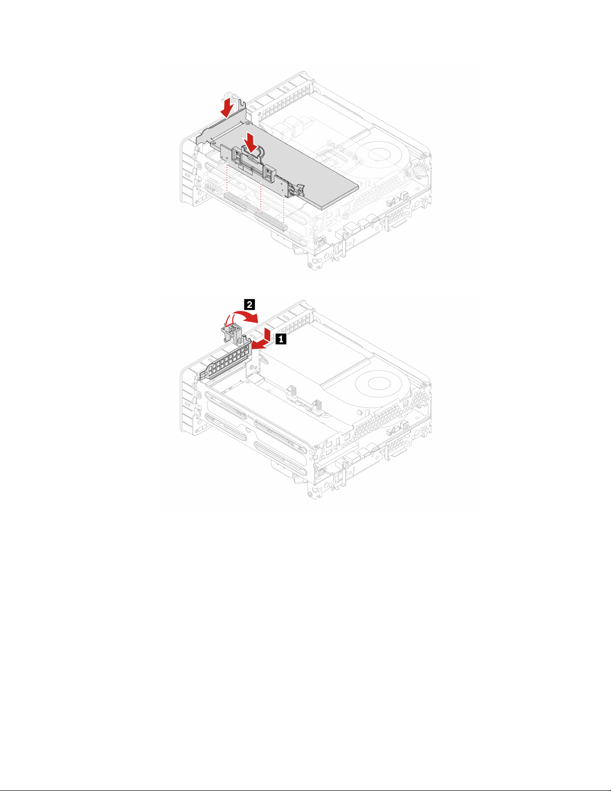
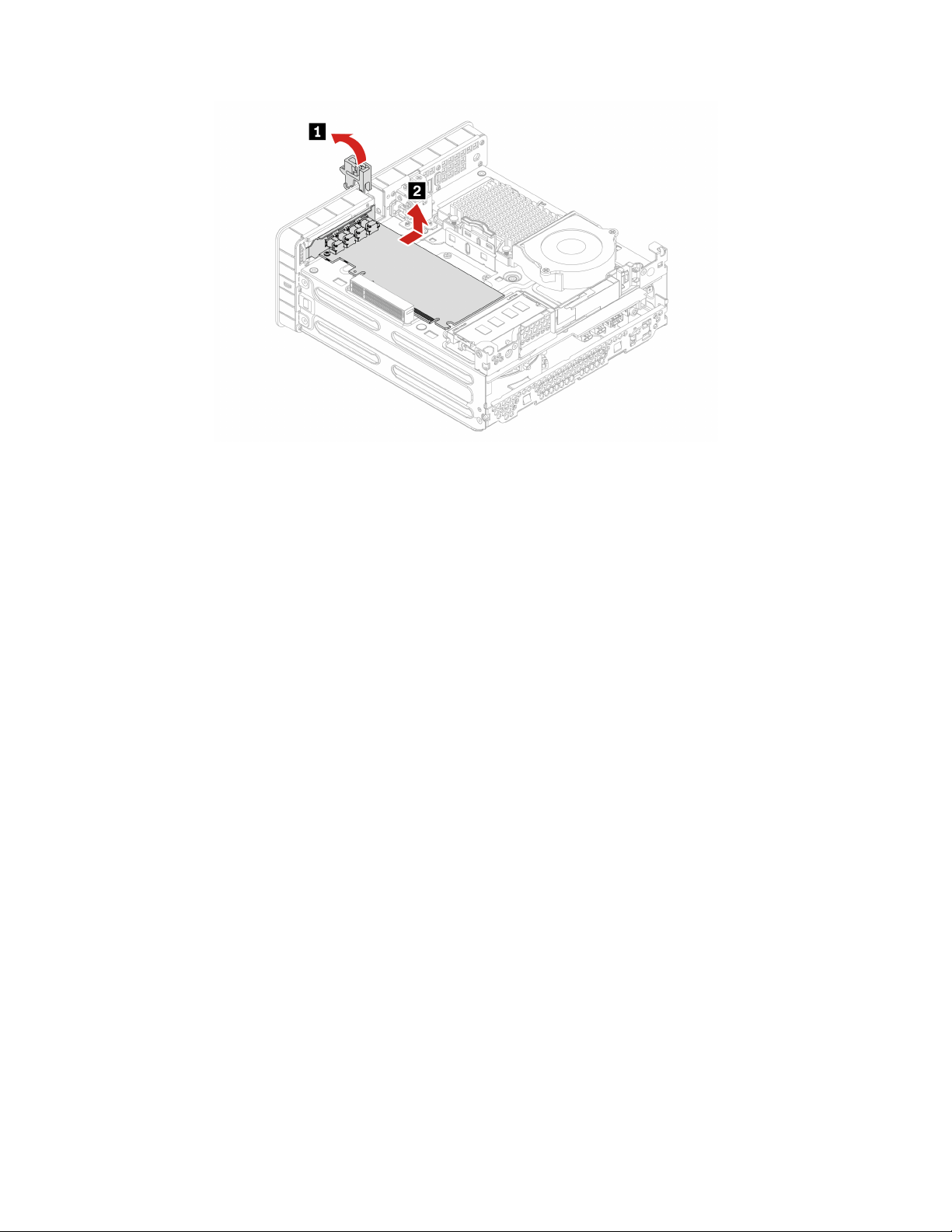
Note: Before installing a new PCI-Express card, remove any PCI-Express connector cables that impede the
installation.
40
P360 Ultra User Guide

Chapter 8. Help and support
Self-help resources
Use the following self-help resources to learn more about the computer and troubleshoot problems.
Resources How to access?
Product documentation:
• Safety and Warranty Guide
• Generic Safety and Compliance Notices
• Setup Guide
• This User Guide
• Regulatory Notice
Go to
https://pcsupport.lenovo.com. Then, follow the on-
screen instructions to filter out the documentation you
want.
Lenovo Support Web site with the latest support
information of the following:
• Drivers and software
• Diagnostic solutions
• Product and service warranty
• Product and parts details
• Knowledge base and frequently asked questions
https://pcsupport.lenovo.com
Ubuntu help information
https://help.ubuntu.com/lts/ubuntu-help/index.html
Lenovo diagnostic tools
For information about Lenovo diagnostic tools, go to:
https://pcsupport.lenovo.com/lenovodiagnosticsolutions
© Copyright Lenovo 2022 41
Call Lenovo
If you have tried to correct the problem yourself and still need help, you can call Lenovo Customer Support
Center.
Before you contact Lenovo
Prepare the following before you contact Lenovo:
1. Record the problem symptoms and details:
• What is the problem? Is it continuous or intermittent?
• Any error message or error code?
• What operating system are you using? Which version?
• Which software applications were running at the time of the problem?
• Can the problem be reproduced? If so, how?
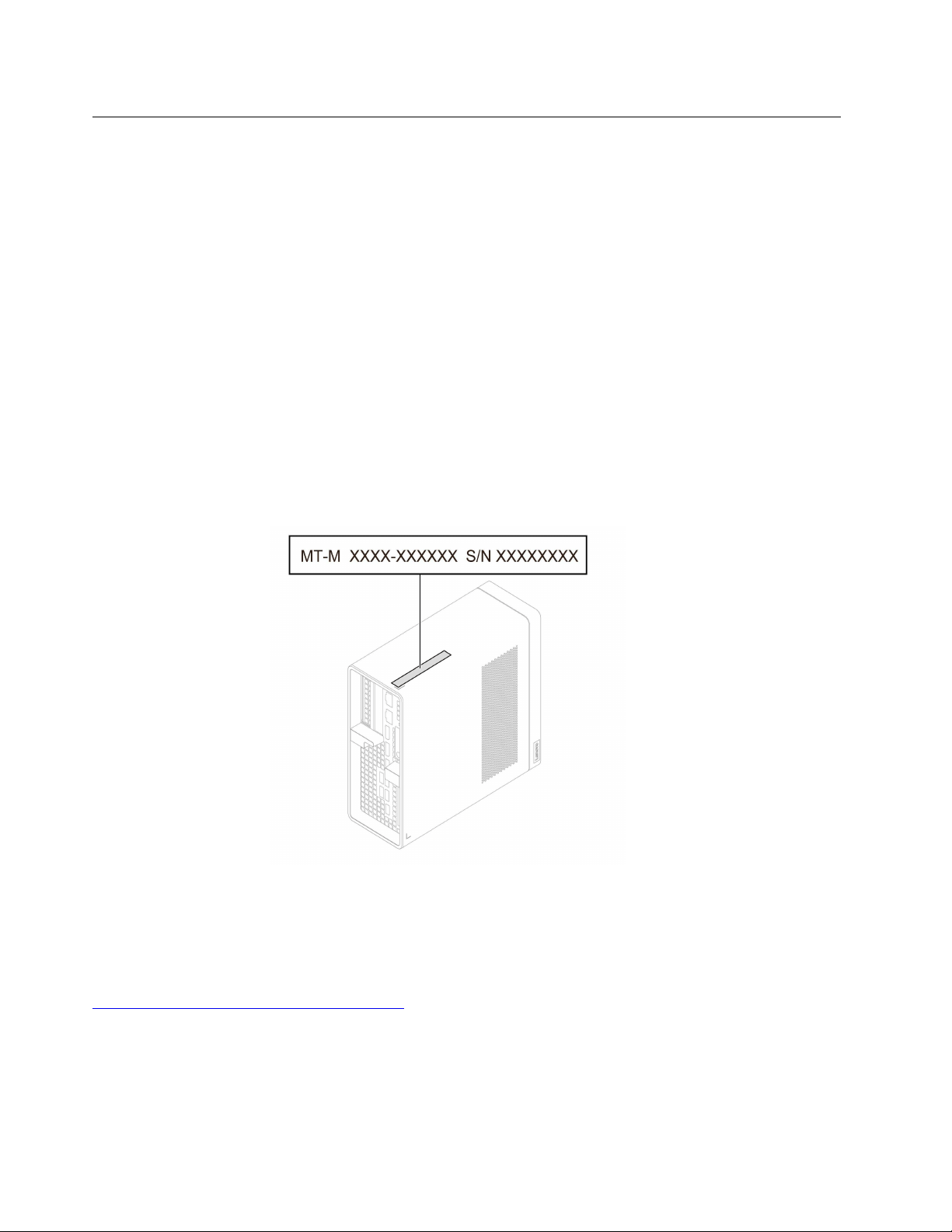
2. Record the system information:
• Product name
• Machine type and serial number
The following illustration shows where to find the machine type and serial number of your computer.
Lenovo Customer Support Center
During the warranty period, you can call Lenovo Customer Support Center for help.
Telephone numbers
For a list of the Lenovo Support phone numbers for your country or region, go to:
https://pcsupport.lenovo.com/supportphonelist
Note: Phone numbers are subject to change without notice. If the number for your country or region is not
provided, contact your Lenovo reseller or Lenovo marketing representative.
42
P360 Ultra User Guide

Services available during the warranty period
• Problem determination - Trained personnel are available to assist you with determining if you have a
hardware problem and deciding what action is necessary to fix the problem.
• Lenovo hardware repair - If the problem is determined to be caused by Lenovo hardware under warranty,
trained service personnel are available to provide the applicable level of service.
• Engineering change management - Occasionally, there might be changes that are required after a product
has been sold. Lenovo or your reseller, if authorized by Lenovo, will make selected Engineering Changes
(ECs) that apply to your hardware available.
Services not covered
• Replacement or use of parts not manufactured for or by Lenovo or nonwarranted parts
• Identification of software problem sources
• Configuration of UEFI BIOS as part of an installation or upgrade
• Changes, modifications, or upgrades to device drivers
• Installation and maintenance of network operating systems (NOS)
• Installation and maintenance of programs
For the terms and conditions of the Lenovo Limited Warranty that apply to your Lenovo hardware product,
see Safety and Warranty Guide that comes with your computer.
Purchase additional services
During and after the warranty period, you can purchase additional services from Lenovo at:
https://pcsupport.lenovo.com/warrantyupgrade
Service availability and service name might vary by country or region.
Chapter 8. Help and support 43

44 P360 Ultra User Guide

Appendix A. System memory speed
The Intel Xeon
®
or Intel Core
™
microprocessor families compatible with this ThinkStation computer feature
an integrated memory controller. The memory controller provides the microprocessor with direct access to
the system memory. Therefore, the system memory speed will be determined by the memory module type,
frequency, size (capacity), the number of memory modules installed, and the microprocessor model.
Notes:
• The actual system memory speed of the memory modules varies depending on the microprocessor
model. For example, your computer comes with 4800 MT/s memory modules, but the microprocessor
only supports up to 4000 MT/s memory modules. Then the system memory speed will be no faster
than 4000 MT/s.
• The microprocessor models supported in your computer might vary. For a list of supported
microprocessor models, contact the Lenovo Customer Support Center.
• The ECC memory modules are not supported on the computer models with Intel Core i5 or i7
microprocessors.
Refer to the following information about the system memory speed:
• Memory module types:
– DDR5 ECC 4800 SoDIMM
– DDR5 non-ECC 4800 SoDIMM
• Memory module operating voltage: 1.1 V
• Memory module frequency: 4800 MT/s
© Copyright Lenovo 2022 45

46 P360 Ultra User Guide

Appendix B. Supplemental information about the Ubuntu
operating system
In limited countries or regions, Lenovo offers customers an option to order computers with the preinstalled
Ubuntu
®
operating system.
If the Ubuntu operating system is available on your computer, read the following information before you use
the computer. Ignore any information related to Windows-based programs, utilities, and Lenovo preinstalled
applications in this documentation.
Access the Lenovo Limited Warranty
This product is covered by the terms of the Lenovo Limited Warranty (LLW), version L505-0010-02 08/2011.
You can view the LLW in a number of languages from the following Web site. Read the Lenovo Limited
Warranty at:
https://www.lenovo.com/warranty/llw_02
The LLW also is preinstalled on the computer. To access the LLW, go to the following directory:
/opt/Lenovo
If you cannot view the LLW either from the Web site or from your computer, contact your local Lenovo office
or reseller to obtain a printed version of the LLW.
Access the Ubuntu help system
The Ubuntu help system provides information about how to use the Ubuntu operating system. To access the
help system from Home Screen, move your pointer to the Launch bar, and then click the Help icon. If you
cannot find the Help icon from the Launch bar, click the Search icon on the bottom left, and type Help to
search it.
To learn more about the Ubuntu operating system, go to:
https://www.ubuntu.com
Get support information
If you need help, service, technical assistance, or more information about the Ubuntu operating system or
other applications, contact the provider of the Ubuntu operating system or the provider of the application. If
you need the service and support for hardware components shipped with your computer, contact Lenovo.
For more information about how to contact Lenovo, refer to the User Guide and Safety and Warranty Guide.
To access the latest User Guide and Safety and Warranty Guide, go to:
https://pcsupport.lenovo.com
Access open-source information
This device includes software made publicly available by Lenovo, including software licensed under the
General Public License and/or the Lesser General Public License (the open source software).
You may obtain a copy of the corresponding source code for any such open source software licensed under
the General Public License and/or the Lesser General Public License (or any other license requiring us to
make a written offer to provide corresponding source code to you) from Lenovo for a period of three years
without charge except for the cost of media, shipping, and handling, upon written request to Lenovo. This
offer is valid to anyone in receipt of this device.
© Copyright Lenovo 2022 47

You may send your request in writing to the address below accompanied by a check or money order for $15
to:
Lenovo Legal Department
Attn: Open Source Team / Source Code Requests
8001 Development Dr.
Morrisville, NC 27560
Please include the version of the OS and the version of the Linux Kernel pre-shipped on this Device as part of
your request. Be sure to provide a return address.
The open source software is distributed in hope it will be useful, but WITHOUT ANY WARRANTY; without
even the implied warranty of MERCHANTABILITY or FITNESS FOR A PARTICULAR PURPOSE. See for
example the GNU General Public License and/or the Lesser General Public License for more information.
To view additional information regarding licenses, acknowledgments and required copyright notices for the
open source software shipped on your Device, go to /usr/share/doc/*/copyright.
48
P360 Ultra User Guide

Appendix C. Compliance information
Note: For more compliance information, refer to Generic Safety and Compliance Notices at
https://
pcsupport.lenovo.com
.
Certification-related information
Product name: ThinkStation P360 Ultra
Machine types: 30G0,30G1,30G2,30G3,30G4,30G5,30G6,30G7,30G8, and 30FY
Further compliance information related to your product is available at
https://www.lenovo.com/compliance.
Operating environment
Maximum altitude (without pressurization)
• Operating: From 0 m (0 ft) to 3048 m (10 000 ft)
• Storage: From 0 m (0 ft) to 12192 m (40 000 ft)
Temperature
• Operating: From 10°C (50°F) to 35°C (95°F)
• Storage: From -40°C (-40°F) to 60°C (140°F)
Relative humidity
• Operating: 20%-80% (non-condensing)
• Storage: 10%–90% (non-condensing)
© Copyright Lenovo 2022 49

50 P360 Ultra User Guide

Appendix D. Notices and trademarks
Notices
Lenovo may not offer the products, services, or features discussed in this document in all countries. Consult
your local Lenovo representative for information on the products and services currently available in your
area. Any reference to a Lenovo product, program, or service is not intended to state or imply that only that
Lenovo product, program, or service may be used. Any functionally equivalent product, program, or service
that does not infringe any Lenovo intellectual property right may be used instead. However, it is the user's
responsibility to evaluate and verify the operation of any other product, program, or service.
Lenovo may have patents or pending patent programs covering subject matter described in this document.
The furnishing of this document does not give you any license to these patents. You can send license
inquiries, in writing, to:
Lenovo (United States), Inc.
8001 Development Drive
Morrisville, NC 27560
U.S.A.
Attention: Lenovo Director of Licensing
LENOVO PROVIDES THIS PUBLICATION "AS IS" WITHOUT WARRANTY OF ANY KIND, EITHER EXPRESS
OR IMPLIED, INCLUDING, BUT NOT LIMITED TO, THE IMPLIED WARRANTIES OF NON-INFRINGEMENT,
MERCHANTABILITY OR FITNESS FOR A PARTICULAR PURPOSE. Some jurisdictions do not allow
disclaimer of express or implied warranties in certain transactions, therefore, this statement may not apply to
you.
Changes are made periodically to the information herein; these changes will be incorporated in new editions
of the publication. To provide better service, Lenovo reserves the right to improve and/or modify the
products and software programs described in the manuals included with your computer, and the content of
the manual, at any time without additional notice.
The software interface and function and hardware configuration described in the manuals included with your
computer might not match exactly the actual configuration of the computer that you purchase. For the
configuration of the product, refer to the related contract (if any) or product packing list, or consult the
distributor for the product sales. Lenovo may use or distribute any of the information you supply in any way it
believes appropriate without incurring any obligation to you.
The products described in this document are not intended for use in implantation or other life support
applications where malfunction may result in injury or death to persons. The information contained in this
document does not affect or change Lenovo product specifications or warranties. Nothing in this document
shall operate as an express or implied license or indemnity under the intellectual property rights of Lenovo or
third parties. All information contained in this document was obtained in specific environments and is
presented as an illustration. The result obtained in other operating environments may vary.
Lenovo may use or distribute any of the information you supply in any way it believes appropriate without
incurring any obligation to you.
Any references in this publication to non-Lenovo Web sites are provided for convenience only and do not in
any manner serve as an endorsement of those Web sites. The materials at those Web sites are not part of the
materials for this Lenovo product, and use of those Web sites is at your own risk.
© Copyright Lenovo 2022 51

Any performance data contained herein was determined in a controlled environment. Therefore, the result
obtained in other operating environments may vary significantly. Some measurements may have been made
on development-level systems and there is no guarantee that these measurements will be the same on
generally available systems. Furthermore, some measurements may have been estimated through
extrapolation. Actual results may vary. Users of this document should verify the applicable data for their
specific environment.
This document is copyrighted by Lenovo and is not covered by any open source license, including any Linux
agreement(s) which may accompany software included with this product. Lenovo may update this document
at any time without notice.
For the latest information or any questions or comments, contact or visit the Lenovo Web site:
https://pcsupport.lenovo.com
Trademarks
LENOVO, LENOVO logo, THINKSTATION, and THINKSTATION logo are trademarks of Lenovo. Intel,
Optane, Core, and Thunderbolt are trademarks of Intel Corporation or its subsidiaries in the U.S. and/or other
countries. Windows is a trademark of the Microsoft group of companies. DisplayPort is a trademark of the
Video Electronics Standards Association. Wi-Fi, Wi-Fi Alliance, and Miracast are registered trademarks of Wi-
Fi Alliance. USB-C is a registered trademark of USB Implementers Forum. All other trademarks are the
property of their respective owners.
52
P360 Ultra User Guide