Loading ...
Loading ...
Loading ...

8
INSTALLATION
studs or lumbers. If the pre-drilled holes don't
align with the studs or lumbers, drill new holes
on the backplate instead.
Connecting the Vent System
• Use 6” or 8" round, or 3-1/4 x 10” rectangular metal
duct (or semi-rigid aluminum duct, follow the local
building codes) to connect the exhaust on the hood
to the duct-work above.
• Use foil tape or duct tape to seal all connections.
Electrical Connection
WARNING: Electrical Shock Hazard. Disconnect power
before servicing.
• In case of a direct connection to the house wiring is
preferred, do the following:
• Disconnect the power.
• Cut off the plug from the power cord.
• Connect the wires from the power cord to the
wires from the house wiring using UL listed
wire connectors.
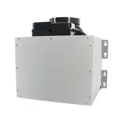
Installing the Blower Unit
• Install the mounting brackets to the edges of
the Blower Unit with the screws provided.
• Install the Blower Unit onto the lumbers in the
attic.
• Route the Speed Control Cord and Duct to the
Blower Unit. Use duct elbows to make turns
only when it's needed. Cut and remove the
excess length when done routing.
• Connect the duct to the Blower Unit's vent in
adapter routed from the Hood Unit.
• Connect the duct from the Blower Unit's vent
out adapter to the roof or wall vent out.
• Connect the Duct from the roof to the vent
opening next to the Black Connection Box.
• Use foil tape or duct tape to seal all connections.
• Connect the Speed Control Cord from the Hood
Unit to the Connection Box on the Blower Unit.
See Electrical Connection section below for how
to properly connect the wires
.
CAUTION
For safety purpose, please connect a separate
Gound Wire to the Blower Unit Chassis screw.
(
Note, don't connect the Ground wire to Blower
Unit's Green Speed Wire!!!)
Important
• If you have an
Awoco Exterior Blower Unit, or any
Blower Unit from other Brands
:
• DO NOT
CONNECT
the wires as shown in the
Wiring Diagram. Any damage from false wiring is
not covered by the warranty.
• Refer to your Blower Unit's USER MANUAL
for
how to properly connect the wires.
Electrical Connection
• Connecting
the
Blower Unit
to the
Hood Unit
is as
simple as "
Match Colors and Connect
":
Simply pick the wires with the same color from
both ends and secure them with a wire nut
connector
. (Refer to the Wiring Diagram in the Test
Run section for how to connect the wires properly.)
• This range hood comes with a power cord with
a 3-prong plug. Connect the power cord to a
designated grounded standard 110V outlet.
Warning
Before Plugging the Power Cord to the Outlet:
• Make sure all wires are connected properly between
the Hood Unit and the Blower Unit.
• Insolate any spare wires with electrical tape to prevent
them from touching each other which will result in a
short circuit.
Loading ...
Loading ...
Loading ...