
MODEL:
E328
E438
E498
E558
E658

Important Information �����������������������������������������������������������2 Recommended Use & Maintenance ������������������������������������9
Setup Overview ������������������������������������������������������������������11
Mounting (for Customer) ����������������������������������������������������14
Prevent Tipping ������������������������������������������������������������������14
Mounting (for Trained Installers) ����������������������������������������15
Mounting Location �������������������������������������������������������������� 16
Orientation ��������������������������������������������������������������������������17
Ventilation Requirements ����������������������������������������������������18
Mounting on Walls or Ceilings �������������������������������������������� 19
Installing and Removing the Optional Table Top Stand �����20
Control Panel ����������������������������������������������������������������������22
Terminal Panel �������������������������������������������������������������������� 23
Wireless Remote Control ����������������������������������������������������24
Wiring Diagram �������������������������������������������������������������������26
Headphones Connection ���������������������������������������������������26
Connecting to a Personal Computer ����������������������������������27
Connecting to a Media Device with HDMI �������������������������28
HDMI-CEC Command ��������������������������������������������������������30
Internal Video Sources �������������������������������������������������������31
Media Player �����������������������������������������������������������������������31
Connecting a USB Device ��������������������������������������������������32
Power On and Off Modes ��������������������������������������������������� 34
Power indicator status ��������������������������������������������������������34
Energy Mode ����������������������������������������������������������������������34
When [RS-232C] is selected for control, [Power supply]
and [Quick Start] are set to [Off] ����������������������������������������34
When [LAN] is selected for control, [Power supply] and
[Quick Start] are set to [Off] �����������������������������������������������35
Operating Range for the Remote Control ���������������������������36
Showing the Information OSD ��������������������������������������������37
Switching Between Sound Modes ��������������������������������������37
Switching Between Picture Modes ������������������������������������� 37
Setting the Aspect Ratio ����������������������������������������������������� 38
OSD (On-Screen Display) Controls ������������������������������������ 39
Using the Media Player Menu ��������������������������������������������41
Creating a Power Schedule ������������������������������������������������45
Using Picture Modes ����������������������������������������������������������46
Setting Security and Locking the Monitor Controls ������������47
Locking the Button Controls �����������������������������������������������48

Controlling the Monitor via RS-232C ����������������������������������51
Controlling the Monitor via LAN ������������������������������������������52
HTTP Browser ���������������������������������������������������������������������53
Commands �������������������������������������������������������������������������57
When a problem occurs with the monitor��� ������������������������59
Nothing is displayed��� ��������������������������������������������������������59
The image is not displayed correctly��� ������������������������������60
An instruction or caution screen is displayed��� �����������������61
Others (when connected to a computer) ���������������������������61
Others (remote control, speakers) �������������������������������������61
Others (when connected via RS-232C or LAN) �����������������62
When using a media player ������������������������������������������������62
When using a video device ������������������������������������������������62
Compatible Signal List �������������������������������������������������������64
E328 �����������������������������������������������������������������������������������66
E438 �����������������������������������������������������������������������������������67
E498 �����������������������������������������������������������������������������������68
E558 �����������������������������������������������������������������������������������69
E658 �����������������������������������������������������������������������������������70
Video Settings ��������������������������������������������������������������������74
Audio Settings ��������������������������������������������������������������������76
Channels ����������������������������������������������������������������������������77
Setup ����������������������������������������������������������������������������������78
Control Settings ������������������������������������������������������������������81
Media Player �����������������������������������������������������������������������82
Schedule ����������������������������������������������������������������������������83
Disposing of your old NEC product �����������������������������������85
Energy Saving ��������������������������������������������������������������������85
About Conversion Cables Used with the AV Terminal �������86

English - 1
To assure continued compliance and prevent possible undesirable interference, ferrite cores may be used when connecting this LCD TV to
video equipment; and maintain at least 400mm spacing to other peripheral device.
Use the attached specied cables with the E658 / E558 / E498 / E438 / E328 of LCD TV so as not to interfere with radio and television
reception.
(1) Please use the supplied power cord.
(2) Please use the supplied shielded HDMI signal cable.
(3) For AV, please use a shielded signal cable.
(4) For mini D-Sub 15-pin and USB, please use a shielded signal cable with ferrite core.
(5) For D-sub 9-pin and Coaxial, please use a shielded signal cable.
(6) Connections to this device must be made with shielded cables with metallic RF / EMI connector hoods to maintain compliance with FCC
Rules and Regulations.
The Federal Communications Commission does not allow any modications or changes to the unit EXCEPT those specied by NEC Display
Solutions of America, Inc. in this manual. Failure to comply with this government regulation could void your right to operate this equipment.
This equipment has been tested and found to comply with the limits for a Class B digital device, pursuant to part 15 of the FCC Rules.
These limits are designed to provide reasonable protection against harmful interference in a residential installation.
This equipment generates, uses and can radiate radio frequency energy, and, if not installed and used in accordance with the instructions, may
cause harmful interference to radio communications.
However, there is no guarantee that interference will not occur in a particular installation.
If this equipment does cause harmful interference to radio or television reception, which can be determined by turning the equipment off and on,
the user is encouraged to try to correct the interference by one or more of the following measures:
• Reorient or relocate the receiving antenna.
• Increase the separation between the equipment and receiver.
• Connect the equipment into an outlet on a circuit different from that to which the receiver is connected.
• Consult the dealer or an experienced radio/TV technician for help.
This device complies with Part 15 of FCC Rules. Operation is subject to the following two conditions.
(1) This device may not cause harmful interference, and (2) this device must accept any interference received, including interference that may
cause undesired operation.
Type of Product: LCD TV
Equipment Classication: Class B Peripheral
Model: E658 E558 E498 E438 E328
Cable-Compatible Analog and Digital Television Receiving Apparatus — Appareil de réception de télévision analogique et numérique
câblocompatible, Canada BETS-7 / NTMR-7.
(1) The contents of this manual may not be reprinted in part or whole without permission.
(2) The contents of this manual are subject to change without notice.
(3) Great care has been taken in the preparation of this manual; however, should you notice any questionable points, errors or
omissions, please contact us.
(4) The image shown in this manual is indicative only. If there is inconsistency between the image and the actual product, the actual
product shall govern.
(5) Notwithstanding articles (3) and (4), NEC will not be responsible for any claims on loss of prot or other matters deemed to result
from using this device.
(6) This manual is commonly provided to all regions so they may contain descriptions that are pertinent for other countries.
English - 2
FOR OPTIMUM PERFORMANCE, PLEASE NOTE
THE FOLLOWING WHEN SETTING UP AND
USING THE LCD TV:
To ensure safe and proper use of the product, this manual uses a number of symbols to prevent injury to you and
others as well as damage to property. The symbols and their meanings are described below. Be sure to understand
them thoroughly before reading this manual.
Failing to heed this symbol and handling the product incorrectly could result in accidents
leading to major injury or death.
Failing to heed this symbol and handling the product incorrectly could result in personal
injury or damage to surrounding property.
Indicates a warning or caution.
This symbol indicates you should be careful of electric shocks.
Indicates a prohibited action.
This symbol indicates something that must be prohibited.
Indicates a mandatory action.
This symbol indicates that the power cord should be unplugged from the power outlet.
UNPLUG THE
POWER CORD
Unplug the power cord if the product malfunctions.
Should the product emit smoke or strange odors or sounds, or if the product has been
dropped or the cabinet broken, turn off the product’s power, then unplug the power cord
from the power outlet. Failure to do so could not only lead to re or electric shock, it
could also result in burn impairment. Contact your dealer for repairs.
Never try to repair the product on your own. Doing so is dangerous.
Do not open or remove the product’s cabinet.
Do not disassemble the product.
There are high voltage areas in the product. Opening or removing product covers and
modifying the product may expose you to electric shock, re, or other risks.
Refer all servicing to qualied service personnel.
Do not use the product if it has structural damage.
If you notice any structural damage such as cracks or unnatural wobbling, please refer
servicing to qualied service personnel. If the product is used in this condition, the
product may fall or cause personal injury.

English - 3
Handle the power cord with care. Damaging the cord could lead to re or electric shock.
• Do not place heavy objects on the cord.
• Do not place the cord under the product.
• Do not cover the cord with a rug, etc.
• Do not scratch or modify the cord.
• Do not bend, twist or pull the cord with excessive force.
• Do not apply heat to the cord.
Should the cord be damaged (exposed core wires, broken wires, etc.), ask your dealer
to replace it.
Do not touch the power plug if you hear thunder. Doing so could result in electric shock.
Please use the power cord provided with this product in accordance with the power
cord table.
If a power cord is not supplied with this product, please contact NEC. For all other
cases, please use the power cord with the plug style that matches the power socket
where the product is located. The compatible power cord corresponds to the AC voltage
of the power outlet and has been approved by, and complies with, the safety standards
in the country of purchase.
For proper installation it is strongly recommended to use a trained service person.
Failure to follow the standard installation procedures could result in damage to the
product or injury to the user or installer.
Please install the product in accordance with the following information.
This product cannot be used or installed without the table top stand or other mounting
accessory for support.
• When installing the optional table top stand, lay this product down on a mat, a
blanket, or another soft material so that the panel is facing downward.
When transporting, moving, or installing the product, please use as many people (two
or more people for the E328/E438/E498/E558 and four or more people for the E658) as
necessary to be able to lift the product without causing personal injury or damage to the
product.
Please refer to the instructions included with the optional mounting equipment for
detailed information about attaching or removing.
Do not cover the vent on the product. Improper installation of the product may result in
damage to the product, an electric shock or re.
Do not install the product in the locations below:
• Poorly ventilated spaces.
• Near a radiator, other heat sources, or in direct sunshine.
• Continual vibration areas.
• Humid, dusty, steamy, or oily areas.
• Outdoors.
• High-temperature environment where humidity changes rapidly and condensation is
likely to occur.
• A ceiling or wall that is not strong enough to support the product and mounting
accessories.
Do not mount the product upside down.
English - 4
9
Prevent tipping and falling for earthquakes or other shocks.
To prevent personal injury or damage to the product caused by tipping over due to
earthquakes or other shocks, make sure to install the product in a stable location and
take measures to prevent falling.
The measures to prevent falling and tipping are intended for reducing the risk of injury,
but may not guarantee the effectiveness against all earthquakes.
• When using the product with the optional table top stand, fasten the product to a wall
using a cord or chain that can support the weight of the product in order to prevent
the product from falling.
Depending on the table top stand, the stand has the structure for preventing tipping.
Please refer to the table top stand manual.
• Use commercially-available clamps and screws (M6) to secure it to the product.
• Be sure to remove the cord or chain from the wall before moving the product to
prevent personal injury or damage to the product.
• Do not attempt to hang the product using an installation safety wire.
• Please install the product in an area on the wall or ceiling strong enough to support
the weight of the product.
• Prepare the product using mounting accessories, such as hook, eyebolt, or mounting
parts, and then secure the product with a safety wire. The safety wire must not be
tight.
• Please make sure the mounting accessories are strong enough to support the
product weight and size before installing it.
Stability Hazard.
The product may fall, causing serious personal injury or death. To prevent injury, this
product must be securely attached to the oor/wall in accordance with the installation
instructions.
Many injuries, particularly to children, can be avoided by taking simple precautions such
as:
• ALWAYS use stands or installation methods recommended by the manufacturer of
the product set.
• ALWAYS use furniture that can safely support the product.
• ALWAYS ensure the product is not overhanging the edge of the supporting furniture.
• ALWAYS educate children about the dangers of climbing on furniture to reach the
product or its controls.
• ALWAYS route cords and cables connected to your product so they cannot be tripped
over, pulled or grabbed.
• NEVER place a product in an unstable location.
• NEVER place the product on tall furniture (for example, cupboards or bookcases)
without anchoring both the furniture and the product to a suitable support.
• NEVER place the product on cloth or other materials that may be located between
the product and supporting furniture.
• NEVER place items that might tempt children to climb, such as toys and remote
controls, on the top of the product or furniture on which the product is placed.
If the existing product is going to be retained and relocated, the same considerations as
above should be applied.
English - 5
Do not place this product on a sloping or unstable cart, stand or table. Doing so could
lead to falling or tipping and cause personal injury.
Do not insert objects of any kind into the cabinet slots. It may cause electric shock, re,
or product failure. Keep objects away from children and babies.
Do not spill any liquids into the cabinet or use your product near water.
Immediately turn off the power and unplug your product from the wall outlet, then refer
servicing to qualied service personnel. It may cause an electric shock or start a re.
Do not use ammable gas sprays to remove dust when cleaning the product. Doing so
could lead to a re.
TO PREVENT FIRE OR SHOCK HAZARDS, DO NOT EXPOSE THIS UNIT TO RAIN OR MOISTURE. ALSO, DO NOT
USE THIS UNIT’S POLARIZED PLUG WITH AN EXTENSION CORD RECEPTACLE OR OTHER OUTLETS UNLESS THE
PRONGS CAN BE FULLY INSERTED.
REFRAIN FROM OPENING THE CABINET AS THERE ARE HIGH VOLTAGE COMPONENTS INSIDE.
REFER SERVICING TO QUALIFIED SERVICE PERSONNEL.
English - 6
Handling the power cord.
Handle the power cord with care. Damaging the cord could lead to re or electric shock.
• When connecting the power cord to the product’s AC IN terminal, make sure the
connector is fully and rmly inserted.
• Fasten the power cord to the product by attaching the clamp to prevent loose
connection.
• Do not connect or disconnect the power cord with wet hands.
• When connecting or disconnecting the power cord, pull the power cord out by holding
onto its plug.
• When cleaning the product, for safety purposes, unplug the power cord from the
power outlet beforehand. Regularly dust off the power cord by using a soft dry cloth.
• Before moving the product, make sure the product power is off, then unplug the
power cord from the power outlet and check that all cables connecting the product to
other devices are disconnected.
• When you are not planning to use the product for an extended period of time, always
unplug the power cord from the power outlet.
Do not bind the power cord and the USB cable. It may trap heat and cause a re.
Do not connect to a LAN with excessive voltage.
When using a LAN cable, do not connect to a peripheral device with wiring that might
have excessive voltage. Excessive voltage on the LAN port may cause an electric
shock.
Do not climb on the table where the product is installed. Do not install the product on
a wheeled table if the wheels on the table have not been properly locked. The product
may fall, causing damage to the product or personal injury.
Installation, removal, and height adjustment of the optional table top stand.
• When installing the table top stand, handle the unit with care to avoid pinching your
ngers.
• Installing the product at the wrong height can cause tipping.
Please install your product at proper height to prevent personal injury or damage to
the product.
Do not push or climb on the product. Do not grab or hang onto the product.
The product may fall, causing damage to the product or personal injury.
Do not impact the LCD panel surface, it can cause serious damage to the product or
personal injury.
English - 7
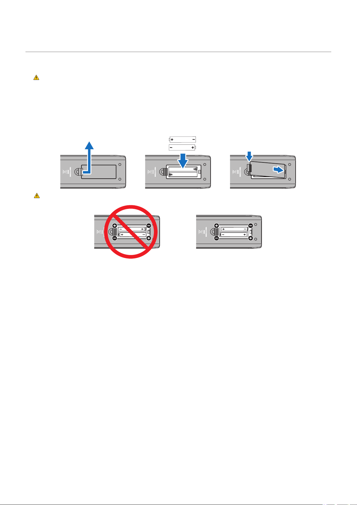
Incorrect usage of batteries can result in leaks or bursting.
• Insert batteries matching the (+) and (–) signs on each battery to the (+) and (–) signs
of the battery compartment.
• Do not mix battery brands.
• Do not combine new and old batteries. This can shorten battery life or cause liquid
leakage of batteries.
• Remove dead batteries immediately to prevent battery acid from leaking into the
battery compartment.
• Do not touch exposed battery acid, it may injure your skin.
• Disposal of a battery into re or a hot oven, or mechanically crushing or cutting of a
battery, can result in an explosion.
• Leaving a battery in an extremely high temperature surrounding environment, or
a battery subject to extremely low air pressure, can result in an explosion or the
leakage of ammable liquid or gas.
• Contact your dealer or local authorities when disposing of batteries.
9
Suitable for entertainment purposes at controlled luminous environments, to avoid
disturbing reections from the screen.
We recommend wiping clean the ventilation holes a minimum of once a month. Failure
to do so could lead to re or electric shock or damage to the product.
To ensure the product’s reliability, please clean the ventilation holes at the rear side of
the cabinet at least once a year to remove dirt and dust. Failure to do so could lead to
re or electric shock or damage to the product.
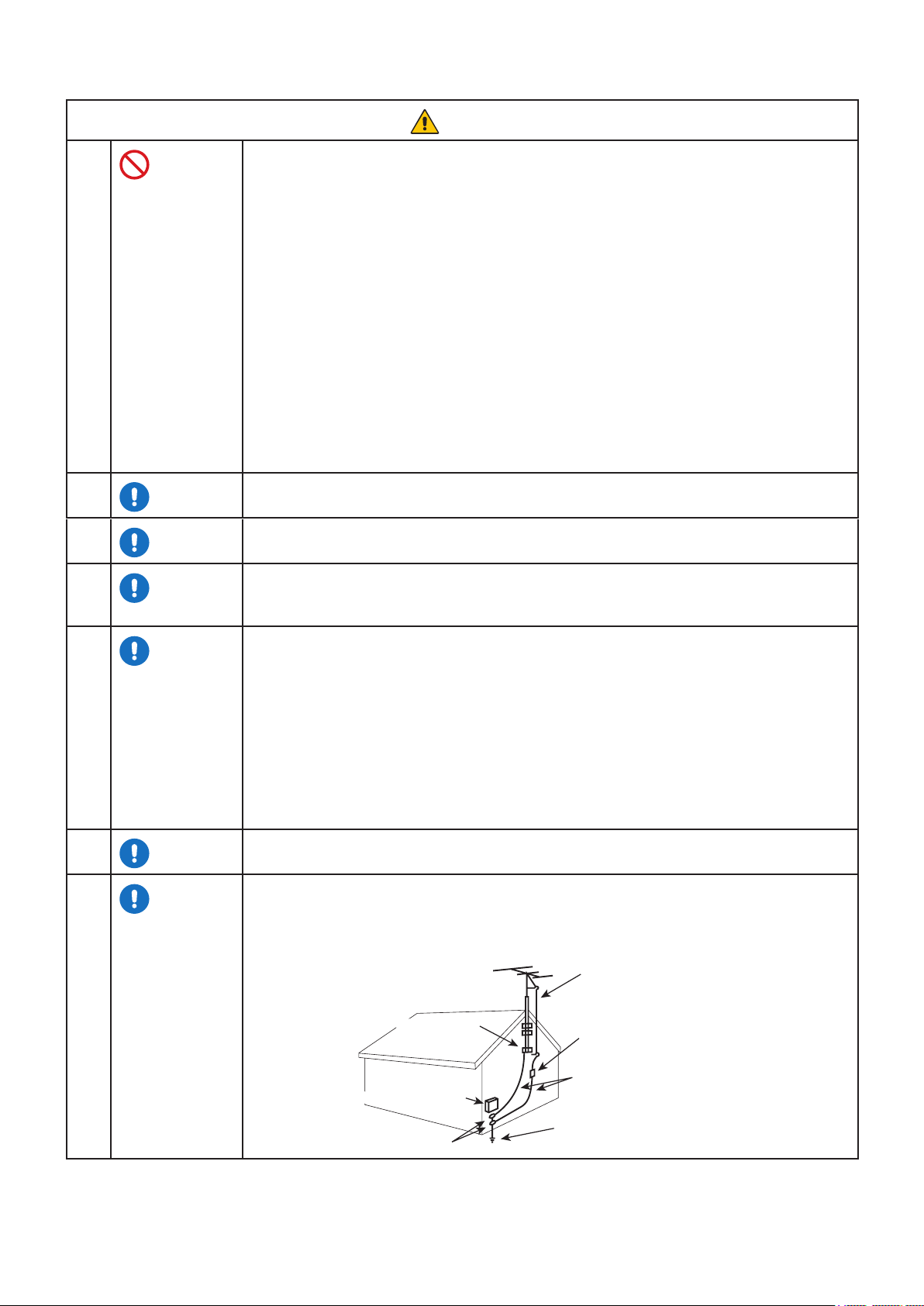
If an outside antenna is connected to the receiver, conrm that the antenna system is
grounded to protect against voltage surges and built up static charges. Section 810 of
the National Electric Code, ANSI / NFPA No. 70-1984, provides information with respect
to proper grounding for the mast and supporting structure, grounding of the lead-in
wire to an antenna discharge unit, size of grounding connectors, location of antenna
discharge unit, connection to grounding electrodes and requirements for the grounding
electrode.
The cable distribution system should be grounded (earthed) in accordance with ANSI/
NFPA 70. the National Electrical Code (NEC), in particular Section 820.93, Grounding of
Outer Conductive Shield of a Coaxial Cable.
Rest your eyes periodically by focusing on an object at least 5 feet away. Blink often.
To the TV system installer: This reminder is provided to call attention to Article 820-
44 of the National Electric Code that provides guidelines for proper grounding and, in
particular, species that the cable ground shall be connected to the grounding system of
the facility, as reasonably close to the point of cable entry as possible.
Antenna lead-in wire
Antenna discharge unit
(NEC Section 810-20)
Grounding conductors
(NEC Section 810-21)
Power service grounding
electrode system (NEC Art 250 Part H)
NEC National Electric Code
Ground clamp
Electric service equipment
Ground clamps
English - 8
CAUTION: TO REDUCE THE RISK OF ELECTRIC SHOCK, MAKE SURE POWER CORD IS UNPLUGGED FROM WALL
SOCKET. TO FULLY DISENGAGE THE POWER TO THE UNIT, PLEASE DISCONNECT THE POWER CORD
FROM THE AC OUTLET. DO NOT REMOVE COVER (OR BACK). NO USER SERVICEABLE PARTS INSIDE.
REFER SERVICING TO QUALIFIED SERVICE PERSONNEL.
This symbol warns user that uninsulated voltage within the unit may have sufcient magnitude to cause electric
shock. Therefore, it is dangerous to make any kind of contact with any part inside this unit.
This symbol alerts the user that important literature concerning the operation and maintenance of this unit has
been included. Therefore, it should be read carefully in order to avoid any problems.
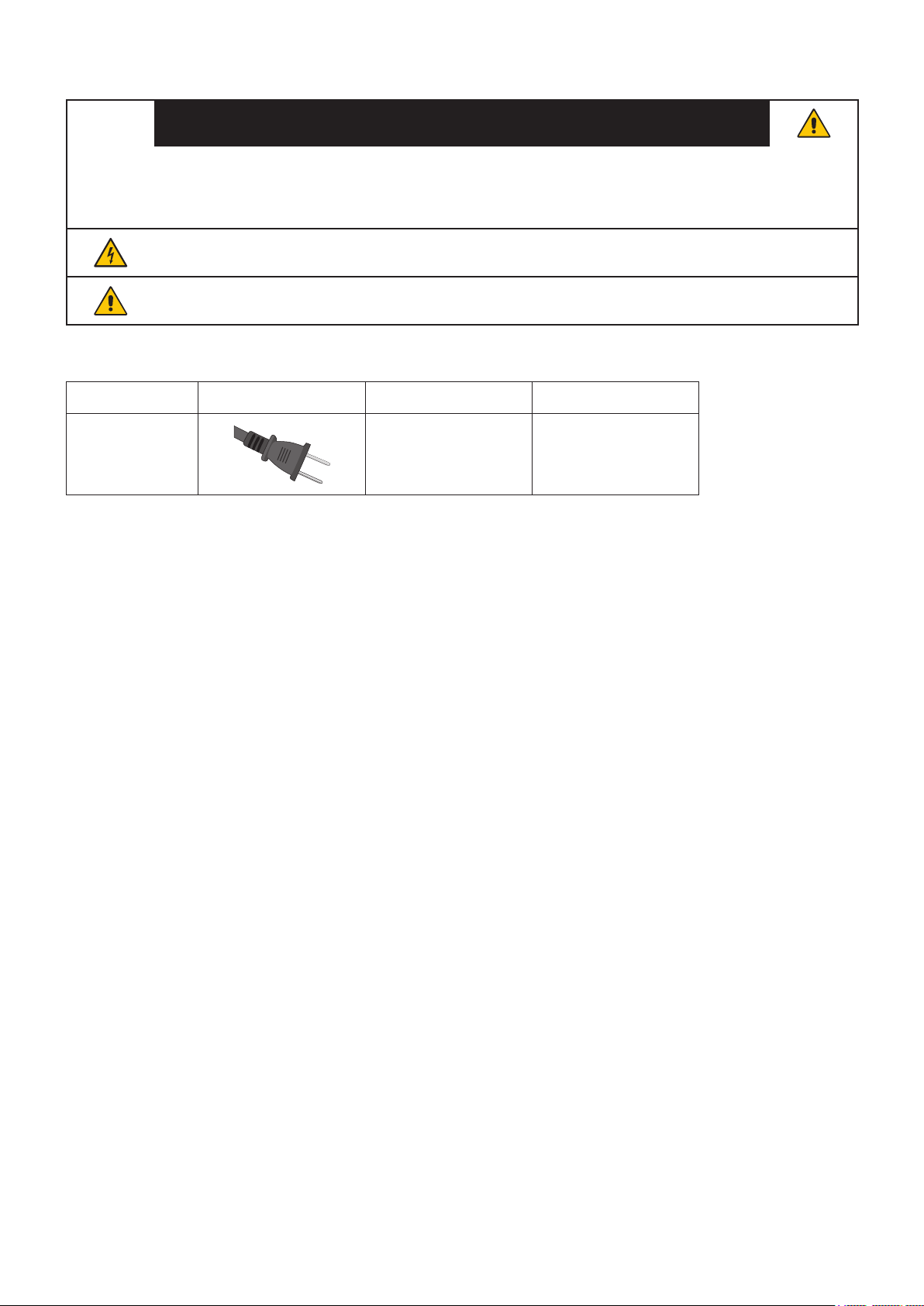
Please use the power cord provided with this TV in accordance with the table below. If a power cord is not supplied
with this equipment, please contact your supplier.
U.S.A./Canada AC 120 V
This LCD TV operates on 120 volts 60 Hz, AC current. Insert the power cord into a 120 volts 60 Hz outlet. The
mains plug is used as the disconnect device and shall remain readily operable.
To prevent electric shock from the TV, do not use with an extension cord, receptacle, or other outlet unless the
blades and ground terminal can be fully inserted to prevent blade exposure.
Never connect the LCD TV to 50 Hz, direct current, or anything other than the specied voltage.

English - 9
To realize the maximum ergonomic benets, we recommend the following:
• For optimum performance of the monitor, allow 20 minutes for warming up. Avoid reproduction of still patterns on the monitor
for long periods of time to avoid image persistence (after image effects).
• Rest your eyes periodically by focusing on an object at least 5 feet away. Blink often.
• Position the monitor at a 90° angle to windows and other light sources to minimize glare and reections.
• Adjust the monitor’s brightness, contrast and sharpness controls to enhance readability.
• Get regular eye checkups.
• Use the preset Size and Position controls with standard input signals.
• Use the preset color settings.
• Use non-interlaced signals.
• Do not view the primary color blue on a dark background. It is difcult to see and may cause eye fatigue due to insufcient
contrast.
• When the LCD screen is dusty, please gently wipe with a soft cloth.
• Clean the LCD screen surface with a lint-free, non-abrasive cloth. Avoid using any cleaning solution or glass cleaner!
• Please do not rub the LCD screen with a hard or abrasive material.
• Please do not apply pressure to the LCD screen surface.
• Please do not use OA cleaner as it will cause deterioration or discoloration on the LCD screen surface.
• Unplug the power supply.
• Gently wipe the cabinet with a soft cloth.
• To clean the cabinet, dampen the cloth with a neutral detergent and water, wipe the cabinet and follow with a dry cloth.
DO NOT clean with benzene thinner, alkaline detergent, alcoholic system detergent, glass cleaner, wax, polish cleaner,
soap powder, or insecticide. Rubber or vinyl should not be in contact with the cabinet for an extended period of time.
These types of uids and materials can cause the paint to deteriorate, crack or peel.
Continuous operating time and warranty.
This product is designed for a maximum daily use of 16 hours. Continual use in excess of 16 hours per day is not
covered by the warranty.

English - 10
Chapter 1 Installation
>
"Setup Overview" on page 11
>
"Mounting (for Customer)" on page 14
>
"Prevent Tipping" on page 14
>
"Mounting (for Trained Installers)" on page 15
>
"Mounting Location" on page 16
>
"Orientation" on page 17
>
"Ventilation Requirements" on page 18
>
"Mounting on Walls or Ceilings" on page 19
>
"Installing and Removing the Optional Table Top Stand" on page 20
For box contents, please refer to the Setup Manual.
Product warranty does not cover damage caused by improper installation.
English - 11
1. Determine the installation location
Please refer to “WARNING 7”, “WARNING 8”, “WARNING 9”, “WARNING 10”, and “WARNING 12”.
To avoid scratching the LCD panel, always place a soft cloth, such as a blanket that is larger than the monitor’s
screen area, on the table before laying the monitor face down when installing the monitor stand or mounting
accessories.
2. Install the remote control batteries
The remote control is powered by two 1.5 V AAA batteries.
To install or replace batteries:
1
3
4
2
Please refer to “CAUTION 8”.
• The batteries supplied with the remote control may become empty quickly depending on their condition.
Therefore, replace them with new batteries early.
If you do not intend to use the remote control for a long period of time, remove the batteries.
3. Connect external equipment
• To protect the external equipment, disconnect the power cord of the monitor before making connections.
• Refer to the user’s manual of your equipment for further information.
Do not connect or disconnect cables when the monitor’s main power or other external equipment’s power is turned
on.
English - 12
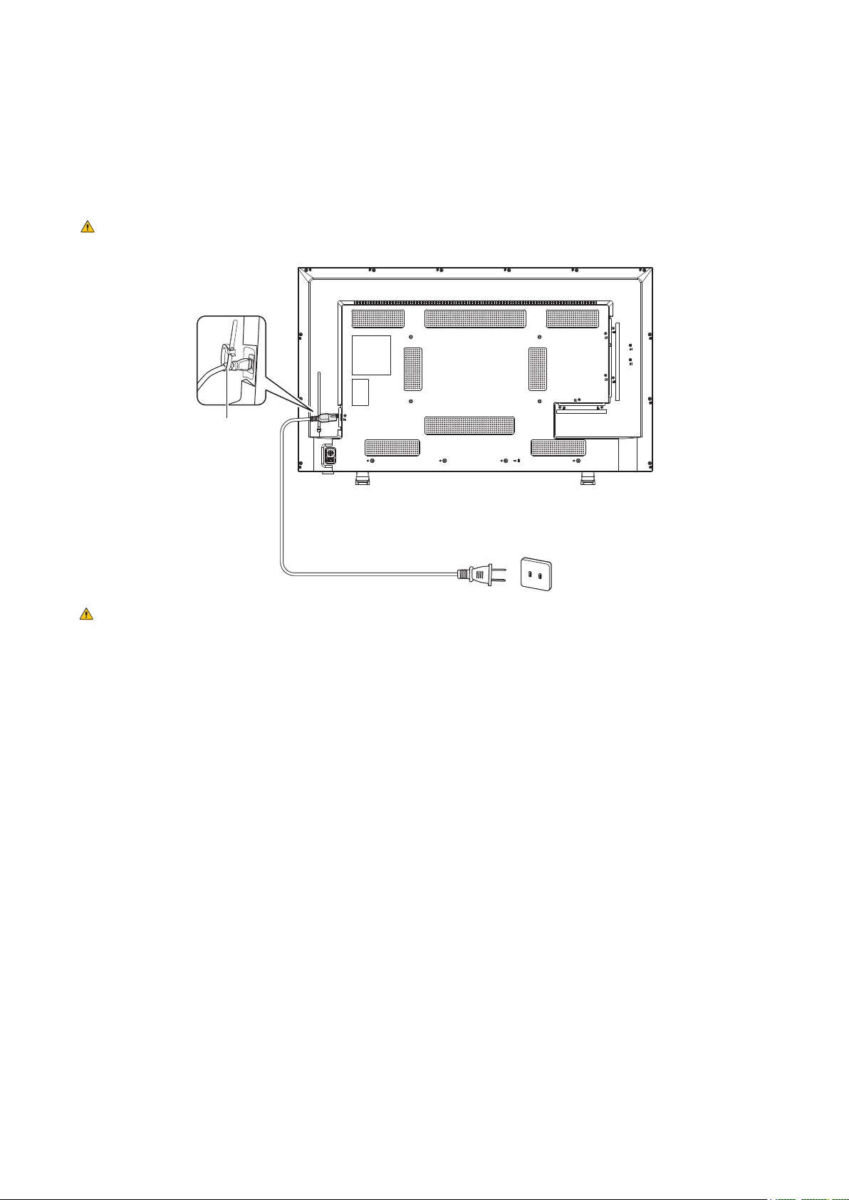
4. Connect the supplied power cord
• Make sure that enough power is supplied to the monitor. Refer to “Power Supply” in the specication.
Connect the power cord to the monitor before plugging it into the power outlet.
1. Connect one extremity of the power cord to the power input terminal of the monitor.
Plug it completely inside.
Please refer to
“CAUTION 1”and “CAUTION 2”.
2. Connect the power plug to an AC power outlet.
Clamp
Please refer to “WARNING 4”, “WARNING 5”, “WARNING 6”, and “WARNING 7”.
The monitor should be installed close to an easily accessible power outlet.
5. Cable information
Use the provided specied cables with this product so as not to interfere with radio and television reception.
For mini D-Sub 15-pin and USB, use shielded signal cables with ferrite core.
For the HDMI and AV cables, use shielded signal cables.
The use of other types of cables and adapters may cause reception problems.
6. Turn the power button on
Switch on the monitor power before turning the computer or external equipment on.
7. Operate the connected external equipment
Select the input source for the monitor to display the video from the external equipment on the screen.
8. Adjust the sound
Make volume adjustments when required.
English - 13
9. Adjust the picture settings
• When using video input terminals (HDMI1, HDMI2, HDMI3, Media Player), adjustment is not required.
• When using an HDMI input terminal, select the appropriate setting between [Mode 0], [Mode 1], and [Mode 2] in [EDID]
under [HDMI Settings] in the [Setup] OSD menu.
10. For long-term use
The backlight used for this monitor has a limited life and its brightness decreases with the usage time.
Also, if the same still image is shown for a long time, “Image Persistence” may occur. “Image Persistence” is a phenomenon
in which the image of an LCD remains visible after the image has been changed.
The “Image Persistence” is gradually eliminated by changing the screen, but if the same screen is shown for too long, the
“Image Persistence” will not disappear.
To avoid shortening the monitor’s lifetime, consider the following:
• Turn off the main power of the monitor when not in use.
• Use the
button on the main unit or the button on the remote control to put the monitor in standby mode.
• If you cover the panel surface of the main unit with a protective cover made of glass or acrylic, the panel surface will be
sealed and the internal temperature will rise.
Use the computer’s power management function or reduce the monitor’s brightness to prevent the internal temperature
from rising.
• Use [Schedule] in the OSD menu to automatically turn the monitor on or in standby mode as required.
When using the schedule function, be sure to set [Current Time settings] in the [Schedule] OSD menu.
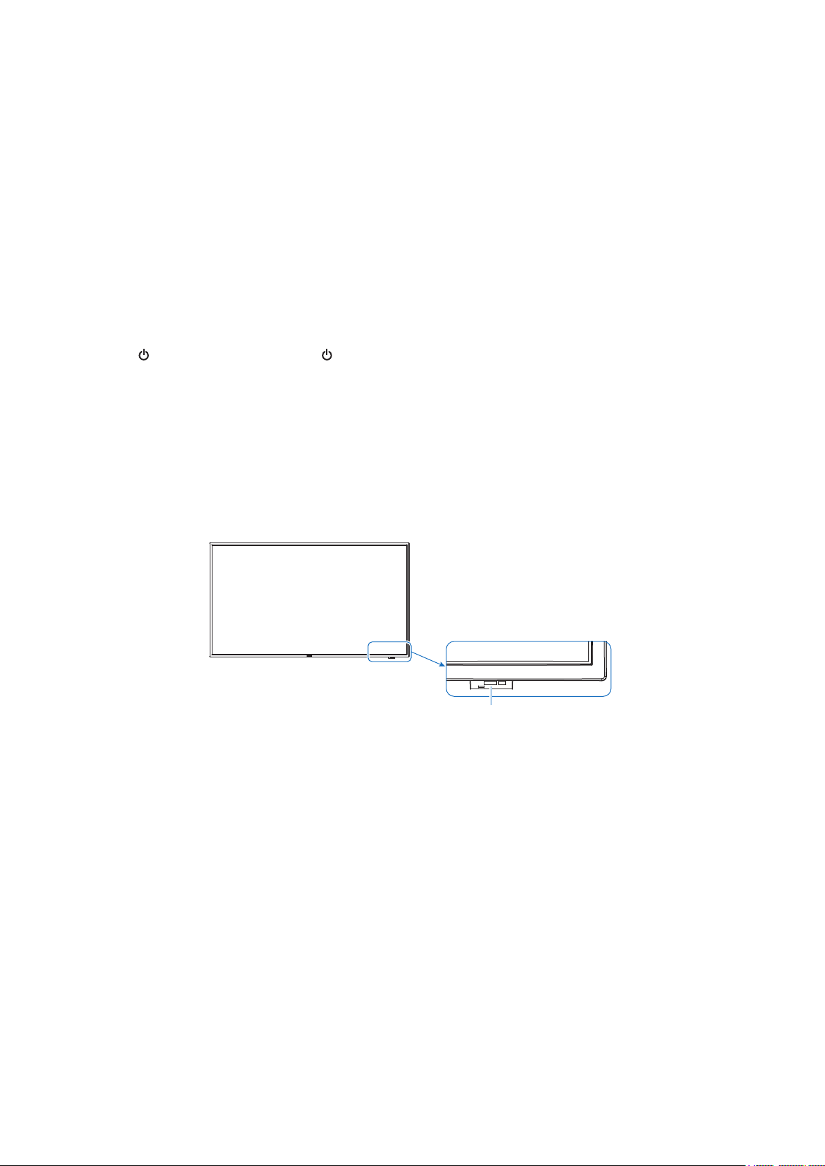
11. Remote control sensor
Be careful not to damage the remote control sensor during installation.
Remote control sensor
English - 14
Please refer to “WARNING 7”, “WARNING 8”, “WARNING 9”, “WARNING 10”, and “WARNING 12”.
Contact your supplier as they may be able to provide a list of qualied installation professionals. Mounting the product on a wall
or ceiling and hiring a technician are the customer’s responsibility.
• Periodically check for loose screws, gaps, distortions, or other problems that may occur with the mounting equipment. If a
problem is detected, refer to the qualied personnel or the supplier for service.
• Depending on the environment, the mounting location may weaken due to natural degradation. Regularly ask the qualied
personnel to inspect the mounting location and carry out maintenance.
NEC Display Solutions assumes no responsibility regarding any damage that may be caused by inadequate installation, misuse,
modication of the product, natural disasters, or other such causes.
When asking the qualied personnel for installation, inform them of the precautions mentioned in “Mounting (for Trained
Installers)”.
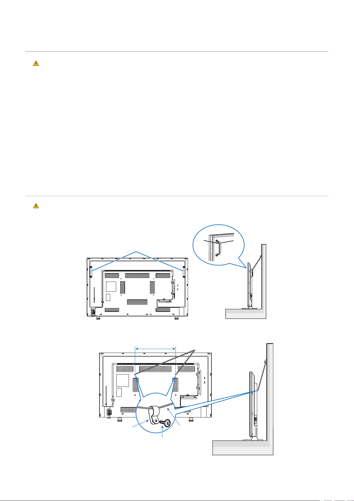
Please refer to “WARNING 7”, “WARNING 9”, and “WARNING 10”.
Commercially-available cord or chain
E498/E438: 400 mm
E328: 100 mm
Screw hole
Commercially-available
cord or chain
Commercially-available screw
(M6, 15 mm)
Commercially-available
clamp
English - 15
Carefully inspect the location where the unit is to be mounted. Not all walls or ceilings are capable of supporting the weight of
the monitor.
The weight of this monitor is provided in the specications.
The product warranty does not cover damage caused by improper installation, re-modeling, or natural disasters.
Failure to comply with these recommendations could result in voiding the warranty.
Pay attention not to obstruct the air vents with the mounting brackets.
Please refer to the
"Important Information" section.
• When using commercially-available mounting brackets, make sure that they
comply with the VESA Flat Display Mounting Interface Standard (FDMI).
• Check that the surface where the brackets will be attached is strong enough.
• Choose commercially-available mounting brackets strong enough to support the
weight of the monitor.
• Prior to mounting, inspect the installation location to ensure that it is strong
enough to guaranty safety.
• Pay attention not to obstruct part of the air vents of the monitor with the brackets.
• For detailed information, refer to the instructions included with the mounting
equipment.
• There are 4 installation holes on the back. Mount the monitor evenly at the four
locations.
(See “Mounting on Walls or Ceilings” for recommended installation examples.)
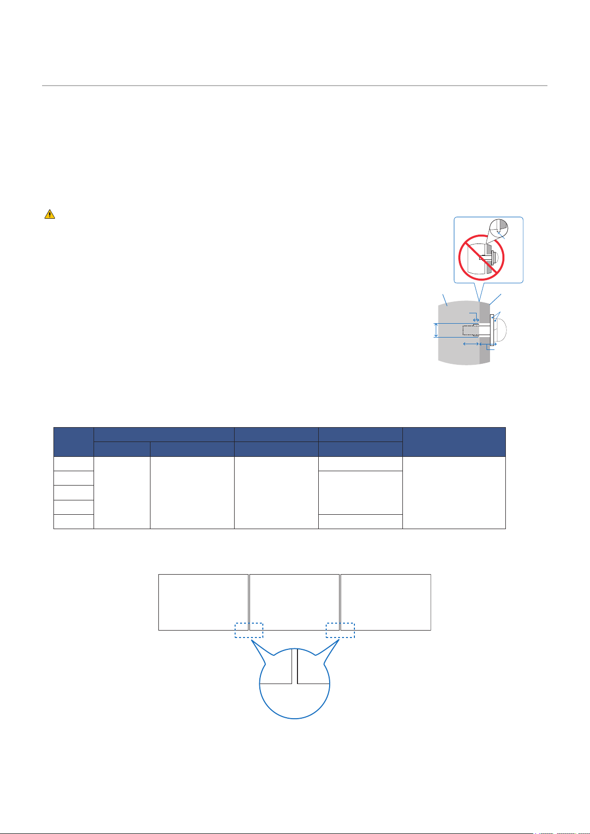
• Use screws of the sizes mentioned below to x the brackets to the monitor. Tighten the screws securely.
E328
M6 13-15 mm ≤ Ø 8.5 mm
2.3 mm
390-520 N•cm
E438
4 mmE498
E558
E658 4.5 mm
When used in a video wall conguration for a long time, a slight expansion of the monitors may happen due to
temperature changes. It is recommended that a gap of over one millimeter is kept between adjacent monitor
edges.
> 1.0 mm
Screw (A)
Monitor
Diameter (C)
Gap
Washers
Mounting
bracket
No thread (D)
Thickness of
the bracket
and washers
(B)
English - 16
When installing the monitor to a wall or a ceiling, use commercially-available wall or ceiling mounting brackets, but also a safety
wire.
Please refer to
“WARNING 9”.
Please refer to
“CAUTION 7”.
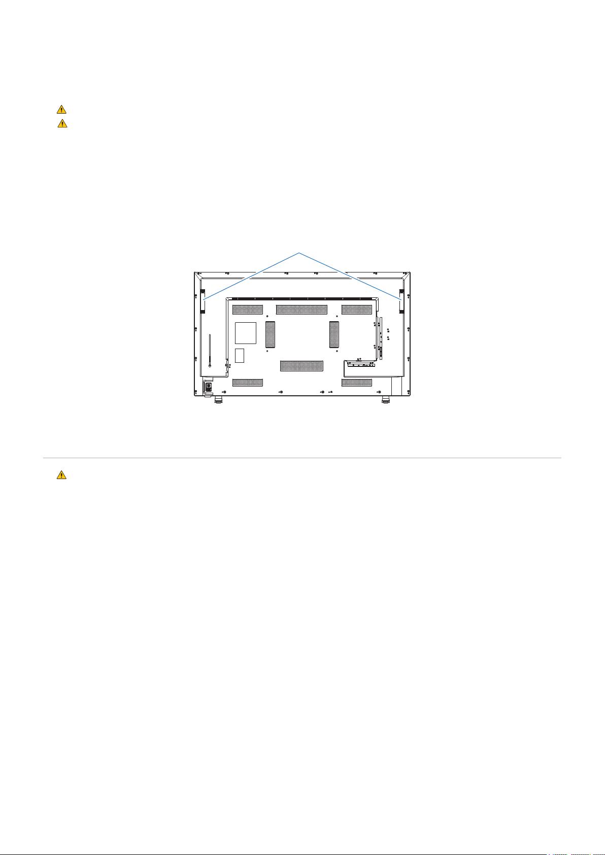
When attaching the safety wire to the monitor’s handle, use the handle locations shown in the gure below.
(Fasten Force: 120 - 190 N•cm)
Attach the safety wire to the handles shown in the gure below.
Safety wire
Please refer to “WARNING 8”.
Allow for adequate ventilation or provide air conditioning around the monitor, so that heat can properly dissipate
away from the monitor and from the mounting equipment.
English - 17
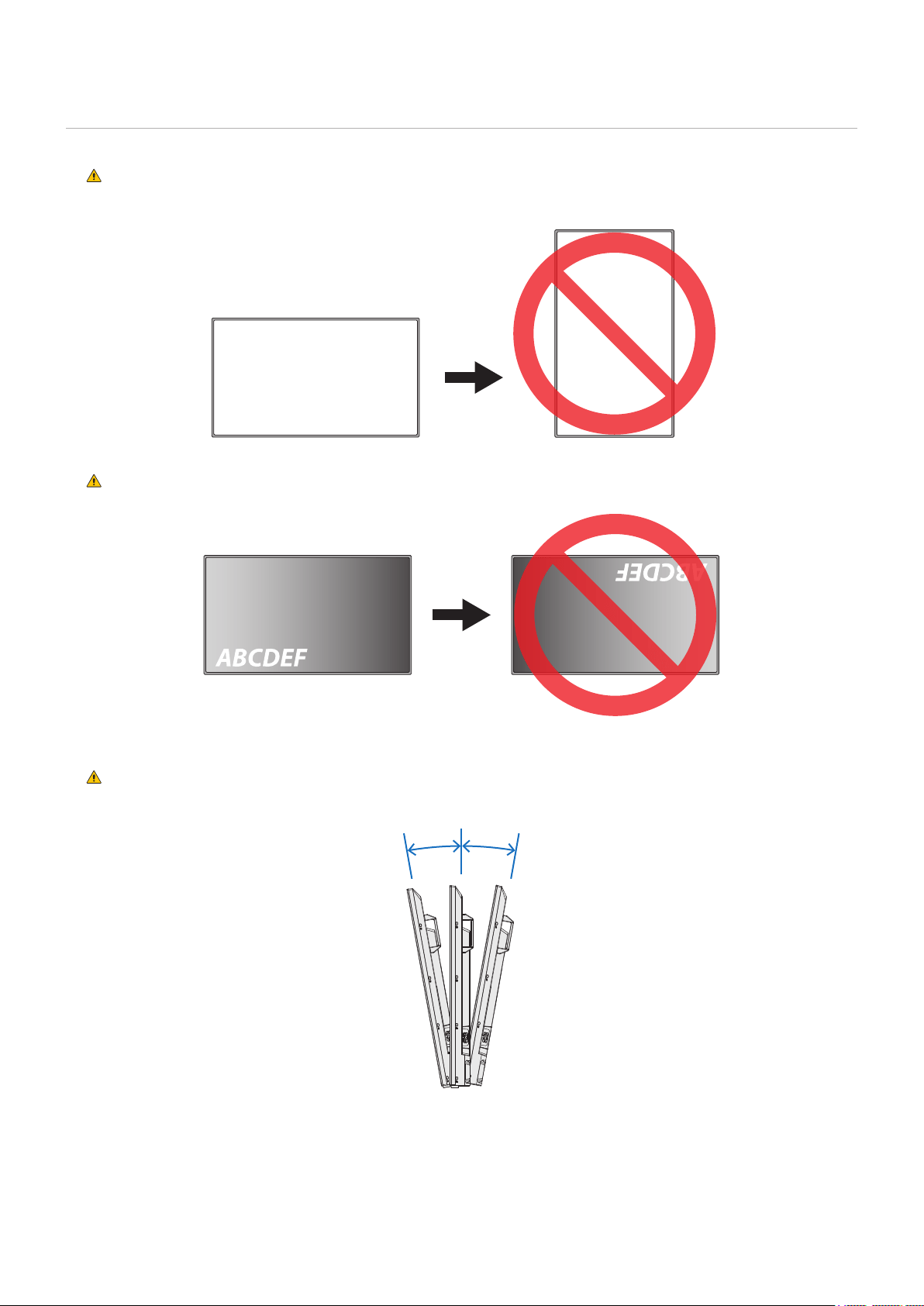
The monitor cannot be used in the portrait orientation.
Do not install it in the portrait orientation.
Otherwise, it may cause a malfunction.
Do not install the monitor upside down.
The monitor cannot be used when inclined 10° or more.
Installing the monitor at an angle of 10° or more may cause a malfunction.
Within 10°Within 10°
English - 18
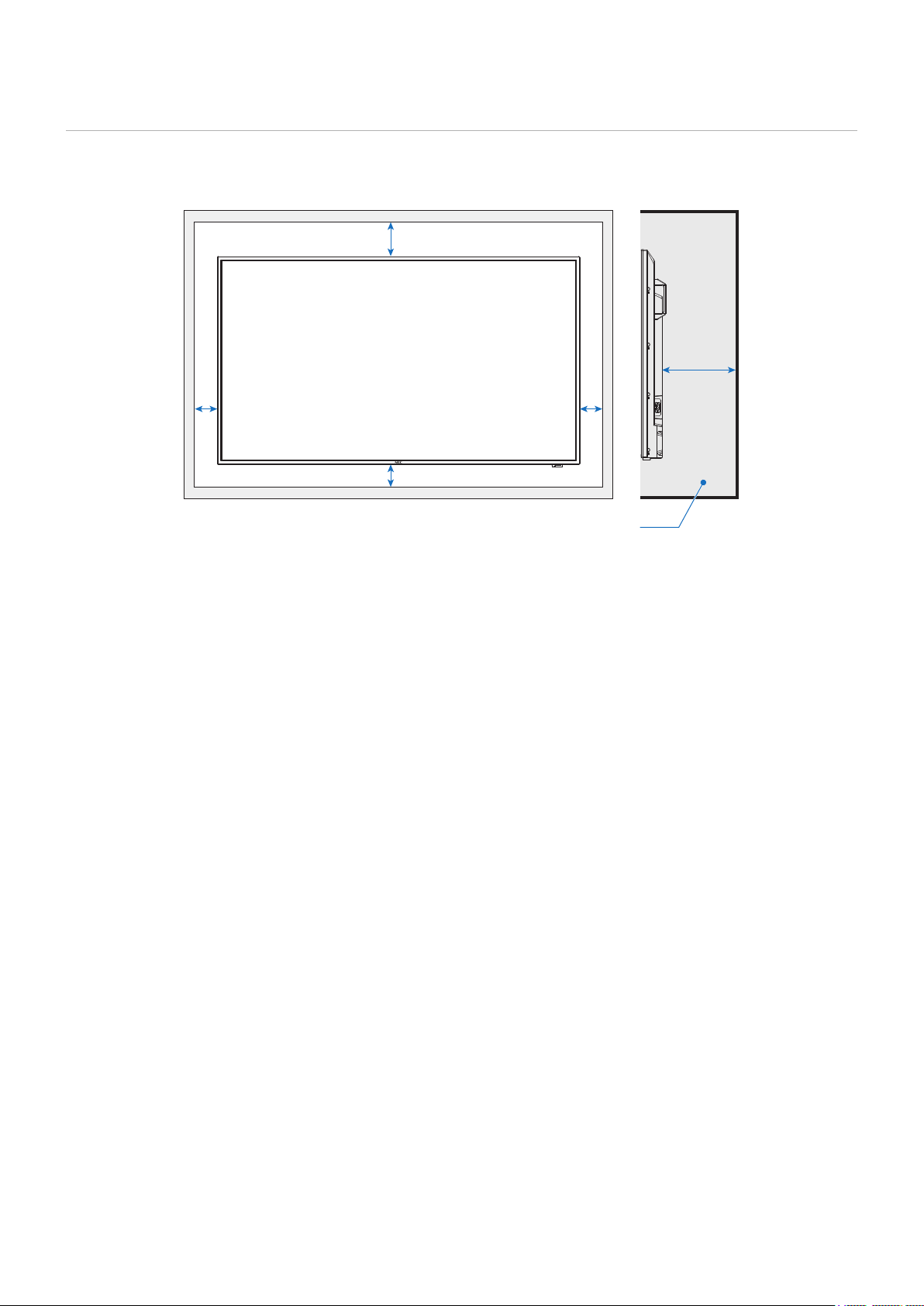
When mounting the monitor in an enclosed space or recessed area, leave adequate room between the monitor and the
enclosure to allow heat to disperse, as shown below.
≤ 40°C
100 mm
100 mm
100 mm
300 mm
60 mm
The maximum environmental operating temperature of the monitor is 40 °C.
This monitor has internal temperature sensors.
If the monitor overheats, a “Warning” appears. If a “Warning” appears, stop using the monitor, turn off the power
and allow it to cool.
For more information on this function, see “Thermal Management” (
page 80).
If the monitor is used in an enclosed area or if the LCD panel is covered with an acrylic protective sheet, check the
temperature around the monitor.
English - 19
Please refer to “WARNING 9”.
Be sure to read this section before mounting the monitor on a wall or a ceiling to guarantee safety.
• It may not be possible to mount the monitor on some walls or ceilings depending on their structure or strength. Ask the
qualied personnel or the supplier to check the mounting location.
Please refer to “WARNING 8”.
1. Place a soft cloth on the table or another at location where the monitor will be laid.
• Make sure that the surface where you will lay the monitor is larger than the monitor screen.
When installing, do not apply excessive force to any part of the monitor by pushing or leaning on it. This may
deform the monitor.
2. Place the monitor on top of the soft cloth.
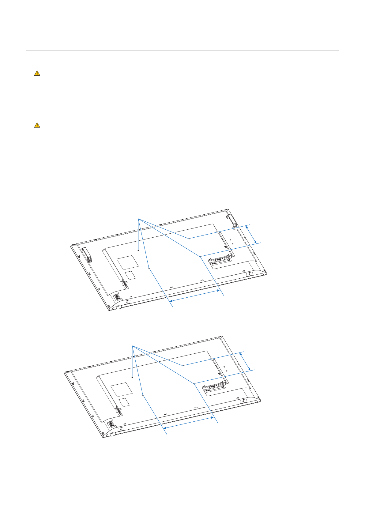
3. Install the commercially-available mounting brackets.
4 installations holes M6 (E558/E658)
200 mm (E558)
400 mm (E658)
400 mm (E558)
600 mm (E658)
4 installations holes M6 (E328/E438/E498)
100 mm (E328)
200 mm (E438/E498)
100 mm (E328)
400 mm (E438/E498)
English - 20
Please refer to “WARNING 9”.
Please refer to
“CAUTION 5”.
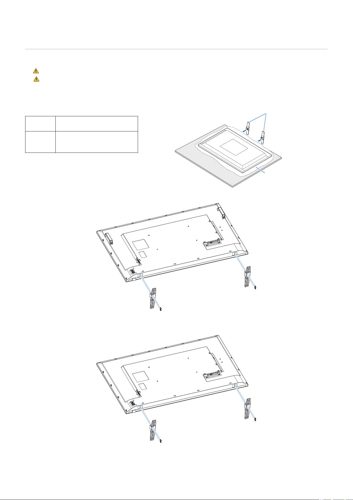
Lay the monitor down on a mat, a blanket, or another soft material so that the panel is facing downward.
The monitor can only be used in the landscape orientation with the table top stand.
E658
E558
ST-55E (screws are included)
E498
E438
E328
ST-32E2 (screws are included)
Stand screw x 4
M5 (17 mm)
Stand screw x 4
M5 (17 mm)
Blanket
Table top stand
Table

English - 22
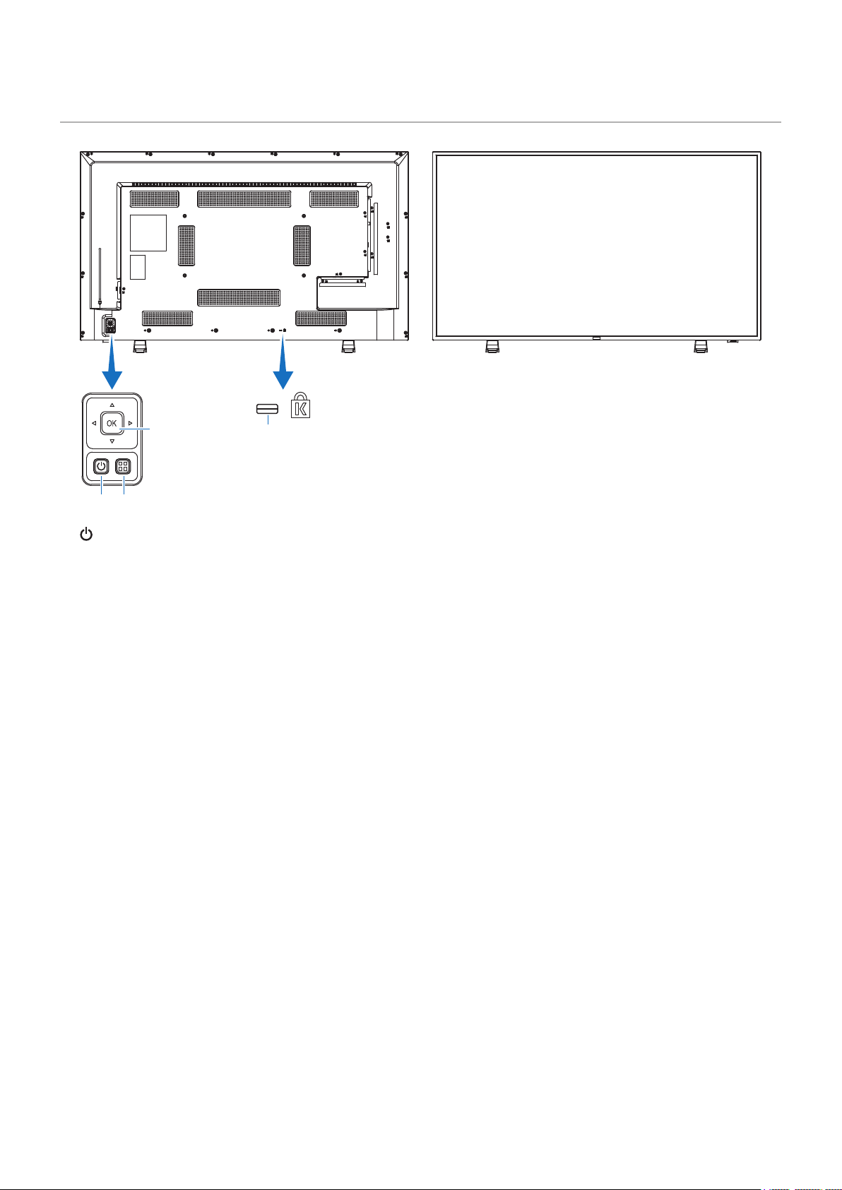
1
4
2
3
1
Switches between power on and standby.
2
Opens the OSD menu when the OSD menu is closed.
Returns to the previous OSD menu when the OSD menu is open.
3
Operates as the setting button to execute the function selected when the OSD menu is open.
Move to the right or left of the OSD control menu.
Moving the left/right keys left and right increases or decreases the adjustment values.
Move up and down in the OSD control menu.
Pressing the left/right keys when the OSD menu is closed directly adjusts the volume.
4
English - 23
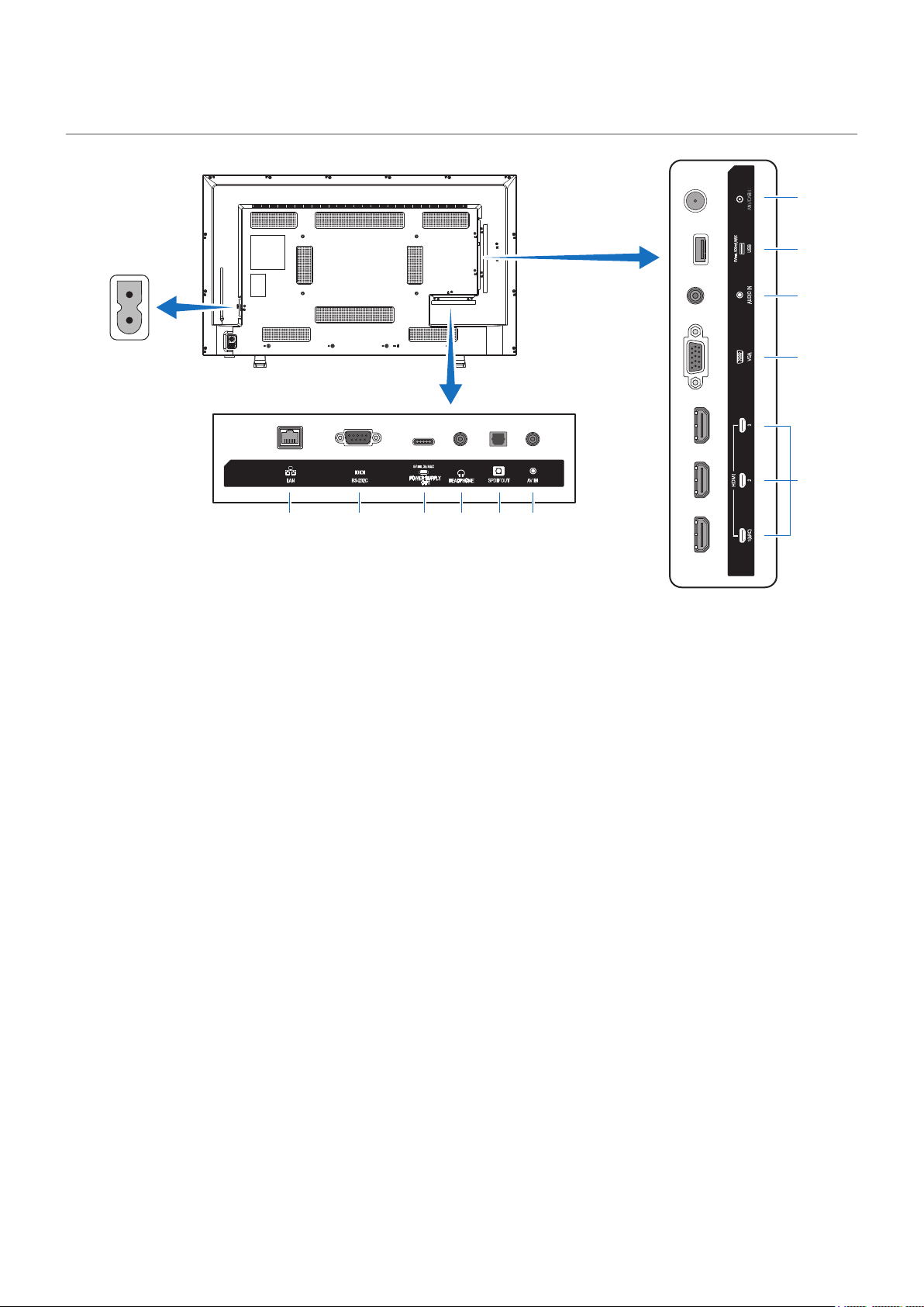
1 2 3 4 5 6
0
!
9
8
7
1
Use the HTTP server function and a Web browser on a
computer to manage the LAN settings of the monitor.
The LAN port of the monitor is not intended
to be connected directly to a public network
(including via routers rented by an Internet
service provider). This is the reason why
connecting the wired LAN port directly to a
public network is forbidden according to the
Telecommunications Business Act.
2
For connection to a computer. Receives control commands
from the computer.
3
Check the shape of the connectors when connecting a USB
cable. When supplying power via the USB Type-C port, use
a USB cable supporting 3 A.
Do not tie the USB cable. Otherwise, it may cause
overheating or re.
4
Outputs the selected audio signal.
5
For connection to an audio device equipped with a digital
audio input terminal.
6
For connection to a video output terminal (composite) of a
video player or other devices.
7
For connection to devices with digital video interface
complying with the HDMI standard. HDMI1 terminal also
supports ARC (Audio Return Channel) for audio output.
Connect an HDMI cable supporting ARC to this terminal.
Connect audio devices supporting ARC to the HDMI1 (ARC)
terminal.
ARC sends the monitor’s sound to the audio
equipment from the HDMI1 ARC terminal.
Use the included ARC-supported HDMI cable.
The audio equipment supporting ARC, such as
AV ampliers, will output the monitor’s audio.
The volume and other functions of the audio
equipment can be controlled with the included
remote control.
8
For connection to the video output terminal (analog) of a
computer.
When connecting the monitor to the video output terminal
(component) of a video player or another device, go to
[Setup] in the OSD menu -> [VGA Options] -> [VGA Mode],
and select [YPbPr].
9
For connection to the audio output terminal of a computer or
another device.
0
Can be used to display photos (still images) and play video
and music les stored in a USB storage device.
Check the shape of the connectors when connecting a USB
storage device or USB cable.
!
Connect to an RF antenna or Analog Cable system.
English - 24
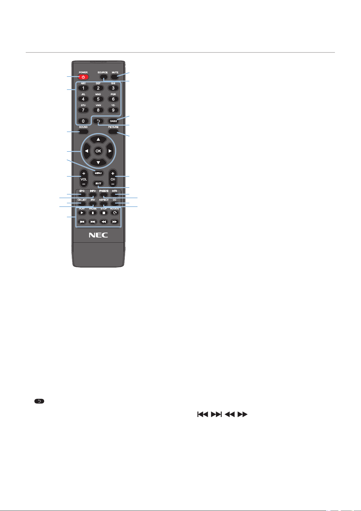
1
7
9
0
$
=
%
#
&
!
4
3
6
8
2
5
@
^
*
(
-
)
1
Switches between power on and off (standby).
To completely turn the power off, disconnect
the power plug from the outlet.
2
Cycles through the available inputs.
The input names are shown as their factory preset name.
3
Silences the audio signal. Press the button again to restore
the previous volume.
4
Press the buttons to enter numerical values, such as the
passwords.
5
Return to previous channel.
6
Press to select different programs under the same channel.
7
Selects the sound mode.
Available sound modes are [Standard], [Music], [Movie], and
[Custom].
8
Selects the picture mode.
Available picture modes are [Dynamic], [Standard], [Energy
Savings], [Conferencing], [HighBright], [Custom], and [HDR
Video].
9
pqtu
Used to navigate inside and select the menus.
0
Increases or decreases the audio output level.
!
Opens and closes the OSD menu.
@
Closes the OSD menu.
#
Press + or - to browse through the channels.
$
Show the program list in DTV source.
%
Shows/Hides the information OSD.
^
Turns the still image function on/off.
&
Press to activate the NTSC tuner sounds such as Stereo,
SAP, Monotone, and languages of the digital tuner.
*
Press to display the Channel List.
(
Press to display the Favorite List.
)
Selects the aspect ratio of the image between [Normal],
[1:1], [Full], and [Zoom].
-
Press to activate the Closed Caption.
=
Used to operate the media player functions and the HDMI
CEC function.

English - 25
Chapter 3 Connections
>
"Wiring Diagram" on page 26
>
"Headphones Connection" on page 26
>
"Connecting to a Personal Computer" on page 27
>
"Connecting to a Media Device with HDMI" on page 28
>
"HDMI-CEC Command" on page 30
>
"Internal Video Sources" on page 31
>
"Media Player" on page 31
>
"Connecting a USB Device" on page 32
• Turn off the power of the monitor, the computer and the external equipment before connecting the monitor to the computer.
• Refer to the externals equipment’s user manuals for available connection types and instructions for each piece of
equipment.
• When the audio output connector of the connected audio device or computer is a stereo mini jack, use an audio
cable without a resistor.
Using an audio cable with a built-in resistor may make it impossible to increase the volume or mute the sound.
We recommend turning off the monitor’s main power before connecting or disconnecting a USB storage device.
Do not connect or disconnect cables when the monitor’s main power or other external equipment’s power is
turned on.
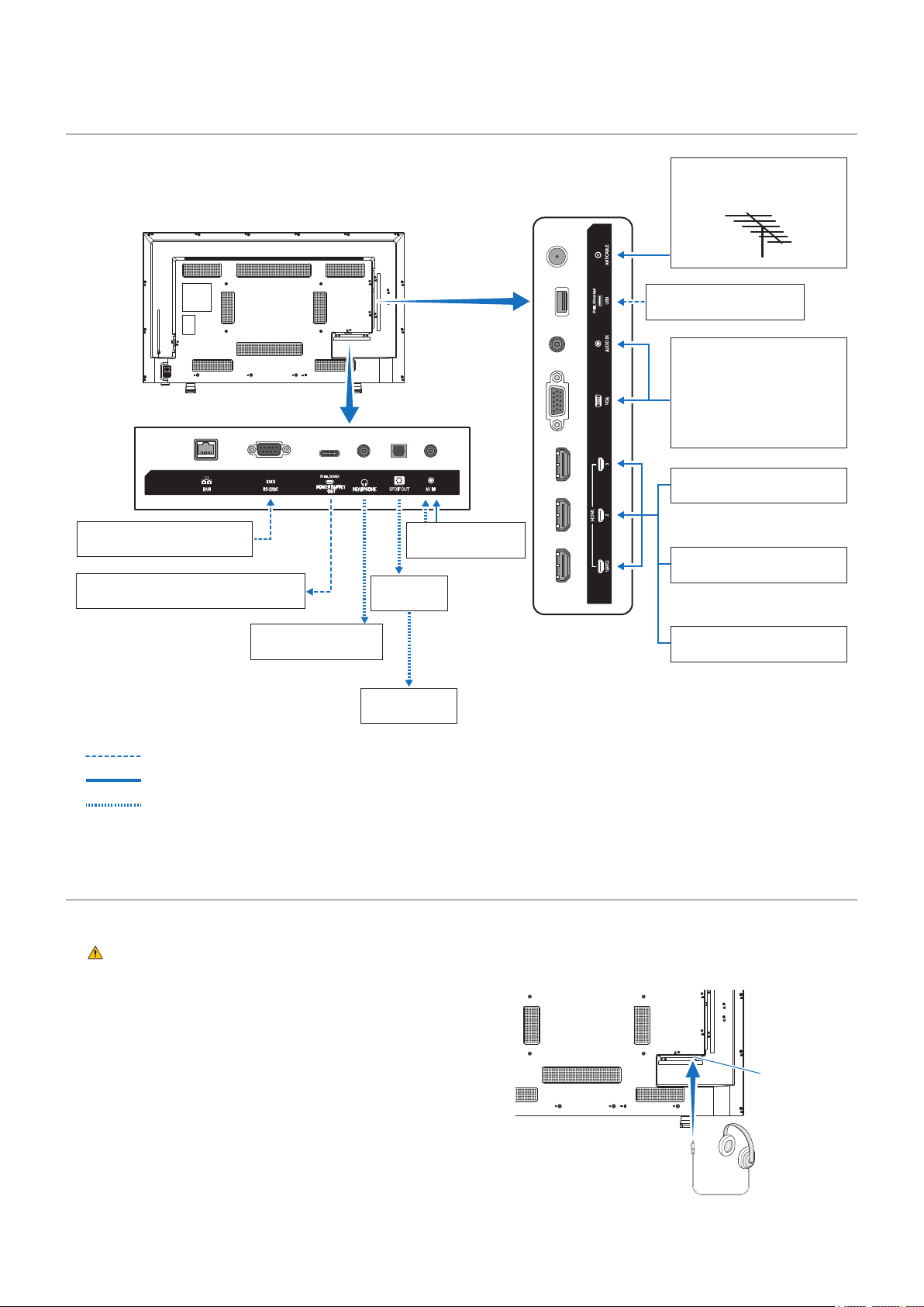
English - 26
Computer (RS-232C)
Video player
(composite)
Computer (HDMI)
Computer (stereo mini jack)
Computer (D-sub)
Video player (stereo mini-jack)
Video player (component)
USB storage device
VHF/UHF Antenna or Cable
TV Use 75-Ohm coaxial
cable
Video player (HDMI)
Blu-ray or DVD player (HDMI)
AV amplier
External
speakers
Headphones
Power supply to external equipment: 5
V/3 A (max)
: Other signals
: Video signal
: Audio signal
When using headphones, connect them to the HEADPHONE terminal of the monitor.
Do not connect the headphones while wearing them.
Otherwise, your ears may be injured depending on the sound volume.
• Headphones with a stereo mini jack plug can
be connected to the monitor. If the plug of your
headphones is too large to enter the connector, buy
a 6.35 mm stereo jack plug to stereo mini jack plug
adapter in your audio store.
The sound from the speakers is muted when
headphones are connected.
Adjustment of the volume control as well as the
equalizer to other settings than the center position
may increase the ear-/headphones output voltage and
therefore the sound pressure level.
When connecting the product to the video
output connector (component) of a video player
or another device, go to [Setup] in the OSD
menu -> [VGA Options] -> [VGA Mode], and
select [YPbPr].
HEADPHONE
terminal

English - 27
The monitor can be connected to and used with video players and computers equipped with an HDMI output. For more
information, refer to the user’s manual of the player or the other devices.
• Use an HDMI cable with the HDMI logo.
• It may take a moment for the signal to appear after turning on the device outputting the HDMI signal.
• Depending on the video card or driver used, the image may not be shown correctly.
• When you use a computer with HDMI, go to the OSD menu [Video] -> [Advanced Video] and set [Overscan] to [Auto] or
[Off].
• If the monitor’s main power is turned on after the connected computer has been turned on, the image may not be
displayed. In this case, turn off the computer then turn it on again.
• If the source signal is 4K (50 Hz/60 Hz), HDCP 2.2 or HDR, got to the OSD menu [Setup] -> [HDMI Settings] -> [EDID]
and set [Mode 2].
• When inputting a 4K signal, use a high-speed or premium high-speed HDMI cable.

English - 28
The monitor can be connected using a single HDMI cable to Blu-ray players, streaming media players, or game consoles for the
highest picture and audio quality. 4K UHD content is shown when the connected media player also supports 4K content.
Supports HDCP (High-bandwidth Digital Contents Protection) coding, a type of digital rights management that prevents high-
denition content, in Blu-ray discs, DVDs and streaming media, from being copied or broadcast illegally.
• Supports 1080p, 1080i, 720p@50 Hz/60 Hz, 480p@60 Hz, 576p@50 Hz, 480i@60 Hz, 576i@50 Hz,
3840×2160 (24 Hz/25 Hz/30 Hz [Mode 1]), 3840×2160 (50 Hz/60 Hz [Mode 2]), 4096×2160 (24 Hz/25 Hz/30 Hz
[Mode 1]), 4096×2160 (50 Hz/60 Hz [Mode 2]).
Connect the HDMI cable when both the media player and the monitor are powered off.
Use an HDMI cable with the HDMI logo.
Some HDMI cables and devices may not show the image correctly due to different HDMI specications.
With the implementation of HDCP, there may be cases in which certain content is protected by HDCP and might
not be displayed. This is not a malfunction.
When audio equipment with the ARC function is connected to the HDMI1 (ARC) terminal of the monitor using the included ARC-
supported HDMI cable, the speakers connected to the audio equipment outputs the monitor’s sound.
• The sound output via HDMI1 (ARC) is not adjustable with the OSD menu.
• When the ARC function is activated, the monitor’s internal speakers are muted.
• The sound of the video displayed on the screen is output to the audio equipment via the HDMI1 (ARC) terminal. Audio
signals not supported by the input terminal used for the video being displayed are not output by the HDMI1 (ARC)
terminal. Refer to “Specications” for the supported signal of each input terminal.
HDMI-CEC provides compatible video devices connected via HDMI with the ability to communicate and allows limited control
between the device and the monitor. For example, turning on a Blu-ray player can immediately switch input to the Blu-ray player
without using the remote control. Not all devices are fully compatible, and, in some cases, the media device manufacturer may
only provide compatibility with its own monitors or TVs. See “HDMI-CEC Command” (page 30).
When supported, the monitor’s remote control can be used to control the video device.

English - 29
1. Connect an HDMI-CEC compatible device to the HDMI terminal.
Press the HDMI button of the remote control.
2. Press the MENU button to open the OSD menu.
3. In the OSD menu, go to [Setup] -> [HDMI Settings] -> and select [On] in [CEC].
4. In the OSD menu, go to [Setup] -> [HDMI Settings] -> [Device list] and press the OK button of the remote control.
When the device search is complete, connected devices are shown by their names.
5. In the OSD menu, select [Yes] under [Search device].
When the device search is complete, the HDMI terminals to which a device is connected are shown with the device name.
If no HDMI-CEC compatible device is found, make sure the device is connected, turned on, that it supports CEC, and that
CEC is enabled.Depending on the manufacturer, the CEC feature may have a different name. Refer to the device’s user
manual.
6. Press the EXIT button of the remote control.
English - 30
Connect an HDMI-CEC compatible device to the HDMI terminal.
CEC
(Consumer
Electronics
Control)
One Touch Play When an HDMI-CEC compatible deviceis
turned on, the monitor connected to
the device with an HDMI cable also
automatically turns on.
After the monitor powers on, Input
terminal automatically switches.
If the monitor is already turned on when
the HDMI-CEC compatible device is
turned on, it only changes the Input
terminal.
Setup
HDMI1
CEC
Auto Turn Off
Audio Receiver
Device list
Off
On
In the OSD menu, go to [Setup] -> [HDMI
Settings] -> and select [On] in [CEC].
Remote Control Pass
Through
The monitor’s remote control button
operation can function with HDMI-CEC
compatible devices connected with an
HDMI cable.
For example, part of the HDMI-CEC
compatible device menu can be operated
using the remote control.
Power Status The connected HDMI-CEC compatible
devices can obtain the monitor’s power
status, such as if the monitor is in standby
mode or on.
System Information This function obtains information from a
connected HDMI-CEC compatible device
(CEC version, physical address, etc.).
Auto Turn Off System Standby If the monitor is set to standby using the
remote control, the HDMI-CEC compatible
device connected with an HDMI cable
also goes into standby at the same time.
If the monitor goes into standby while
an HDMI-CEC compatible device is
recording, the device remains on.
Refer to the user’s manual supplied with
the HDMI-CEC compatible device for
further information.
In the OSD menu, go to [Setup] -> [HDMI
Settings] -> [CEC] and select [Enable] in
[Auto Turn Off].
Audio
Receiver
System Audio
Control
Connect audio equipment with the ARC
function to the HDMI1 (ARC) terminal
using the included ARC-supported HDMI
cable. The Volume buttons of the remote
control can control the volume of the
connected HDMI ARC audio equipment.
While this function is active, the monitor’s
internal speakers are automatically set to
MUTE.
In the OSD menu, go to [Setup] -> [HDMI
Settings] -> [CEC] and select [Enable] in
[Audio Receiver].
Search device Device OSD Name
Transfer
This function is used to obtain the name
of the connected devices.
In the OSD menu, go to [Setup] ->
[HDMI Settings] -> [CEC] -> [Device list]
and press the OK button of the remote
control.
Routing Control By selecting a device name, the HDMI-
CEC compatible device input switches to
the input you selected. After selecting the
device, the remote control operates for
the selected device.
Depending on the connected device, sometimes the device does not work properly.
English - 31
The internal Media Player will play audio and video les that are stored on a USB storage device. See page page 41 for
instructions on using the Media Player.
If the USB storage device connected to the monitor is not recognized, check its format. The USB storage device used with the
Media Player should be in the FAT32 or FAT16 format. For more information on how to format a storage device, see the manual
or the help section of your Windows
®
.
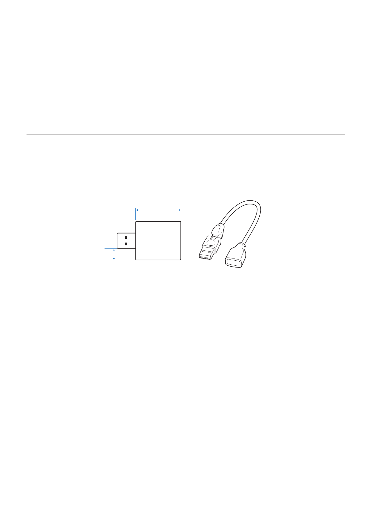
Use a USB storage device of the correct size in accordance with the drawing below.
If the physical size of the USB storage device is larger than the supported size shown below, use a commercially-available USB
extension cable.
Connect the USB storage device to the USB Type-A port of the monitor.
≤ 70 mm
≤ 5 mm
USB storage device
USB extension cable
• The monitor is not guaranteed to work with all USB storage devices sold commercially.
Check that the USB storage device is connected to the USB Type-A port of the monitor.
English - 32
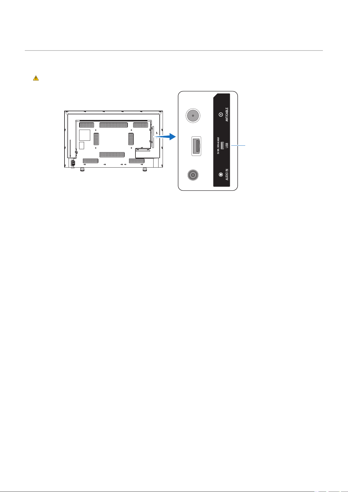
Connect a USB storage device to the USB Type-A of the monitor as shown in the gure below to display images and videos
using the Media Player function.
Please refer to
“CAUTION 2”.
USB Type-A port
• Check the connector shape and orientation when connecting the USB device or cable.
Do not connect a USB storage device to the monitor when the monitor is turned on. To prevent damage to the
monitor and possible corruption of the connected device’s data les, the monitor’s main power switch should be
off before making connections.

English - 33
Chapter 4 Basic Operation
>
"Power On and Off Modes" on page 34
>
"Operating Range for the Remote Control" on page 36
>
"Showing the Information OSD" on page 37
>
"Switching Between Sound Modes" on page 37
>
"Switching Between Picture Modes" on page 37
>
"Setting the Aspect Ratio" on page 38
>
"OSD (On-Screen Display) Controls" on page 39
>
"Using the Media Player Menu" on page 41
>
"Using the Media Player Menu" on page 41
English - 34
The monitor operates as follows in On mode when no signal is input from an external device.
Power indicator Lit blue Flashing red Lit red
The three following modes are available on the monitor.
Setup
Move Select
HDMI1
Energy Mode
Power Save
Quick Start
Auto Power Down
Home
OK
Return
MENU
EXIT
EXIT
Retail
Office
LAN and RS-232C can be selected for the monitor control. The way the energy modes operate varies depending on the
selected control method.
• When no signal is input, “No signal” is displayed and the monitor enters the auto standby mode after a while.
• When a signal is input into the selected input terminal, the On mode is resumed.
When the AV terminal and VGA (YPbPr) terminal are selected, the On mode is not resumed even if a signal is input. In this
case, enable the Quick Start function. (With this function enabled, the On mode is resumed.)
• The monitor does not enter the energy-saving mode when no signal is input. (The On mode is maintained.)
During auto standby mode, if the power cord is disconnected and then plugged again, the monitor will be in
the auto standby mode.

English - 35
• When no signal is input, “No signal” is displayed and the monitor enters the auto power save mode after a while.
• During auto power save mode, the monitor enters the auto standby mode if no LAN signal is received for 3 minutes.
If a LAN signal is input during auto standby mode, the auto power save mode is not resumed. To maintain the auto power
save mode, use the Ofce mode.
• When a signal is input into the selected input terminal, the On mode is resumed.
When the AV terminal and VGA (YPbPr) terminal are selected, the On mode is not resumed even if a signal is input. In this
case, enable the Quick Start function. (With this function enabled, the On mode is resumed.)
• The monitor does not enter the energy-saving mode when no signal is input. (The On mode is maintained.)
• When no signal is input, “No signal” is displayed and the monitor enters the auto power save mode after a while.
The auto power save mode is maintained regardless of LAN signal input.
• When a signal is input into the selected input terminal, the On mode is resumed.
When the AV terminal and VGA (YPbPr) terminal are selected, the On mode is not resumed even if a signal is input. In this
case, enable the Quick Start function. (With this function enabled, the On mode is resumed.)
During auto power save mode and standby mode, if the power cord is disconnected and then plugged
again, the On mode will not be resumed automatically when a signal is detected.
English - 36
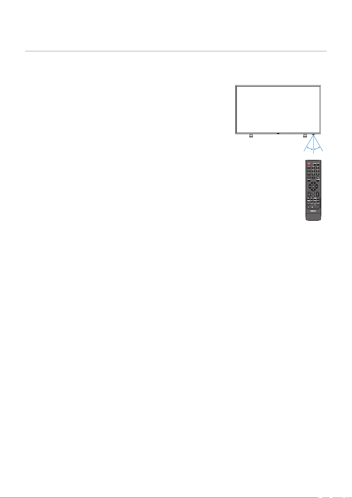
Point the top of the remote control toward the monitor’s remote control sensor during button operation.
Use the remote control within a distance of about 7 m (23 ft.) from the remote control sensor, or within a horizontal and vertical
angle of 30° and within a distance of about 3.5 m (10 ft.).
The remote control system may not function when direct sunlight or
strong illumination strikes the remote control sensor, or near uorescent
lamps.
• Do not expose to strong shock.
• Do not allow water or other liquid to splash on the remote control. If the remote
control gets wet, wipe it dry immediately.
• Avoid exposure to heat and steam.
• Ask your supplier or your municipality for information on how to dispose of the
batteries.
• Do not open the remote control, except to install the batteries.
30°30°
English - 37
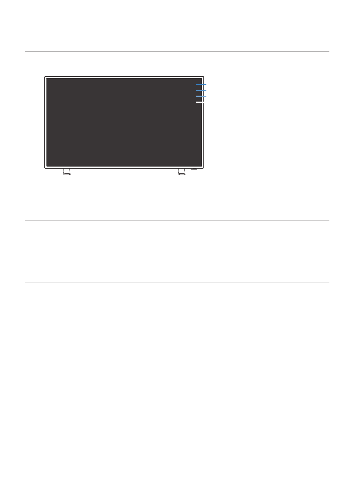
The Information OSD provides information such as the selected video input terminal, resolution, and IP address. Press the INFO
button of the remote control to bring up the information OSD.
1
2
3
4
* When [Information OSD] is set to [On]:
White: Connected to a LAN
Red: Not connected to a LAN
HDMI1
1080p@60Hz
SDR
IP ADDRESS : 192.xxx.x.xx
2
3
4
1
When the input signal is [Media Player], the information OSD will not be displayed.
Press the SOUND button of the remote control to change the Sound Mode setting between Standard, Music, Movie, and
Custom.
Press the PICTURE button of the remote control to change the Picture Mode setting between Dynamic, Standard, Energy
Savings, Conferencing, HighBright, Custom, and HDR Video*.
* HDR Video can be selected only when an HDR signal is input.
English - 38
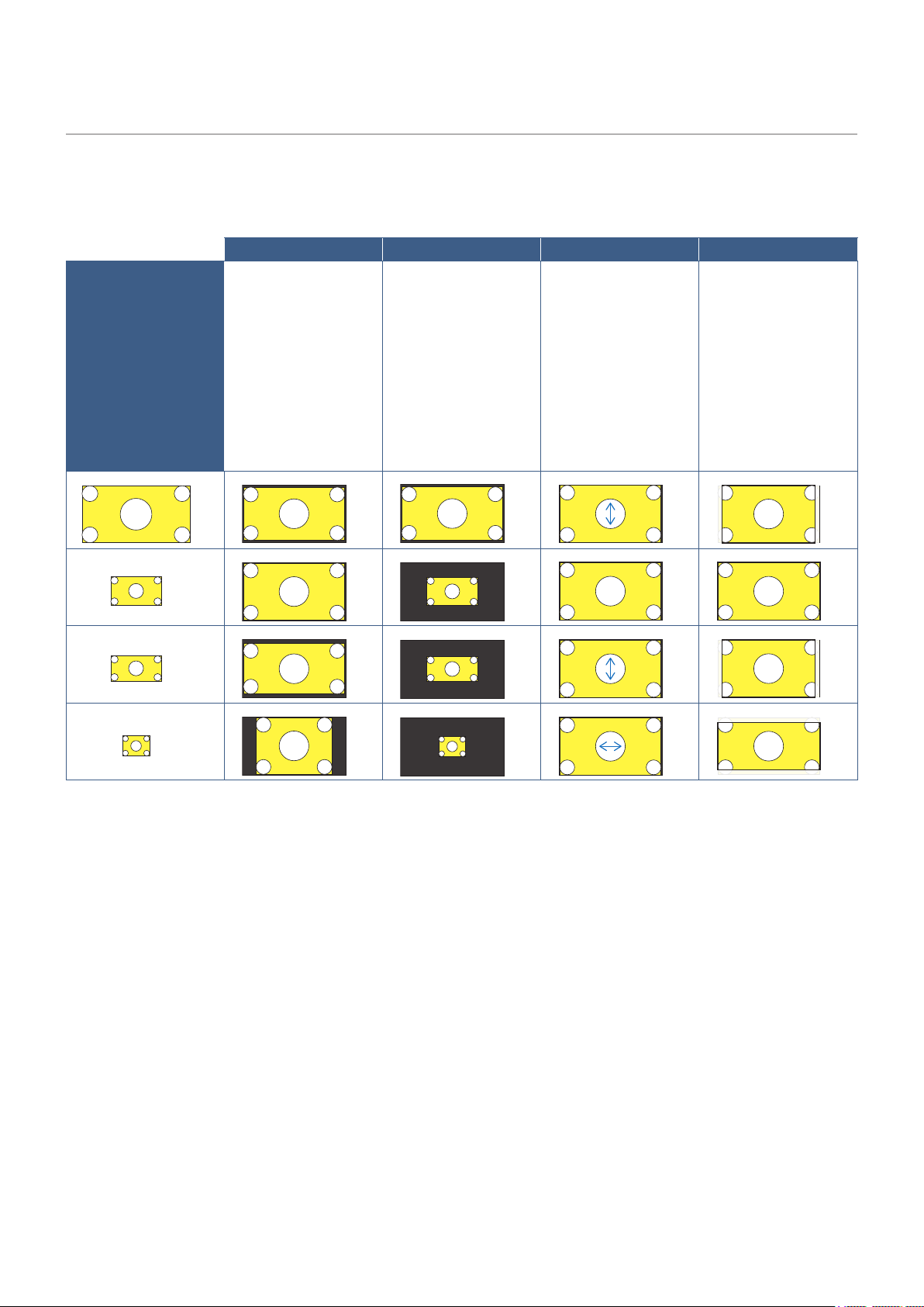
Press the ASPECT button of the remote control to change the Aspect Ratio setting between Normal, 1:1, Full, and Zoom.
This setting cannot be changed when [Media Player] is selected for the input signal.
The aspect ratio of
the input signal is
maintained and the
image is enlarged/
reduced.
• Black bars are
added vertically or
horizontally.
• The screen is not cut,
neither vertically nor
horizontally.
The image is displayed
with the number of panel
pixels corresponding
to the resolution of the
input signal.
When the input signal
is larger than the
number of the panel
pixels, the aspect ratio
is maintained and the
image is reduced.
The aspect ratio of the
input signal is ignored
and the image is
enlarged.
• There are no black
bars, neither vertically
nor horizontally.
• The screen is not cut,
neither vertically nor
horizontally.
The aspect ratio of
the input signal is
maintained and the
image is enlarged.
• There are no black
bars, neither vertically
nor horizontally.
• Part of the image,
vertically or
horizontally, is not
displayed.
4096
2160
3840
2025
3840
2025
3840
2160
3840
2160
1920
1080
3840
2160
1920
1080
3840
2160
3840
2160
1920
960
3840
1920
1920
960
3840
2160
3840
2160
1024
768
2880
2160
1024
768
3840
2160
3840
2160
Note that changing the aspect ratio to compress or stretch an image and display it publicly or for commercial
purposes in coffee shops, hotels, or other such places, may violate the rights of the copyright holder.
English - 39
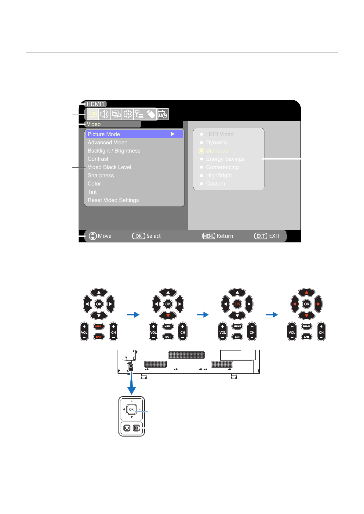
The monitor features an OSD (On-Screen Display) function that allows the user to easily adjust the screen.
By operating the menu displayed at the top of the screen, you will be able to adjust the brightness and the other screen settings.
The OSD screen is composed of the following elements.
Video
Move Select
HDMI1
Picture Mode
Advanced Video
Backlight / Brightness
Contrast
Video Black Level
Sharpness
Color
Tint
Reset Video Settings
HDR Video
Dynamic
Standard
Energy Savings
Conferencing
HighBright
Custom
OK
Return
MENU
EXIT
EXIT
Input source
Selected
main menu
Sub menu
Adjustment
settings
Key guide
Main menu icons
Wireless
Remote
Control
Press MENU to open and
close the OSD menu.
Press the EXIT button to close
the OSD menu et stop OSD
operations.
Press
q
to navigate
through the sub menus.
Press the OK button to
select an item.
Press
p
,
q
,
t
, and
u
to select an adjustment
item and adjust the
values.
Monitor’s control panel
Press
p
,
q
,
t
, and
u
to select an adjustment item and adjust the values.
Press the OK button to select an item.
Press MENU/EXIT to open and close the OSD menu.
English - 40
The function of each OSD menu element is briey explained below. For more details on the content of the menu, see “OSD
Controls List” (
page 73).
Select one of the default picture modes, manually adjust the color settings, adjust the aspect
ratio, and adjust the other settings related to the image.
Adjust the volume, balance, equalizer, and the other settings related to the audio.
Congure the Channels and Time Zone settings.
Display the monitor information, select the language, or return the settings to their default
values.
Congure settings such as the network information.
Congure the USB Demo Mode and other settings.
Create auto power on/off schedules for the monitor and set the sleep timer.
English - 41
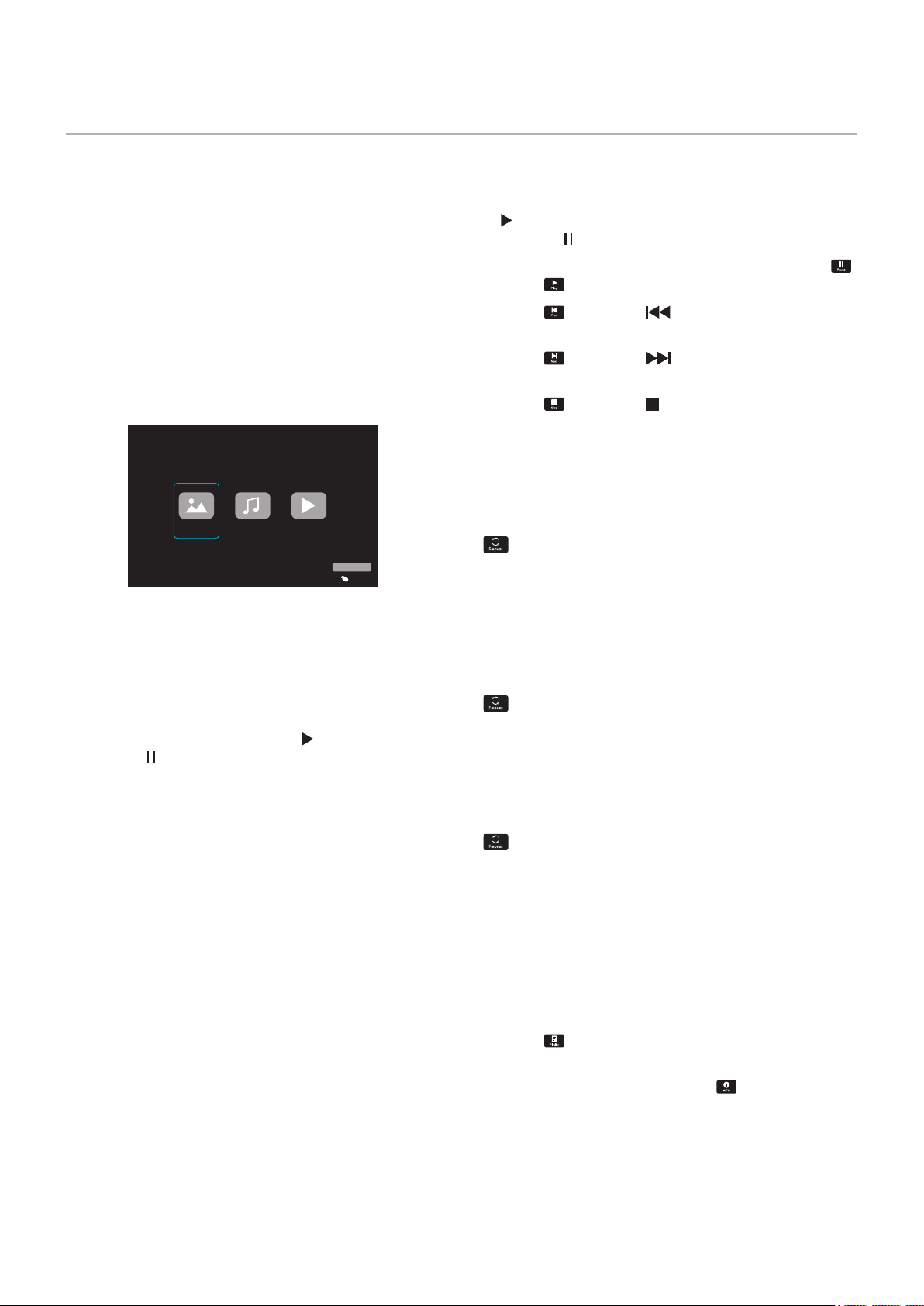
The Media Player plays image, video, and music les
located on a USB storage device connected to the USB
Type-A port of the monitor (
page 23).
To open the Media Player menu, press the SOURCE button
of the remote control and select [Media Player].
Connect the USB storage device where the
les are stored to the USB Type-A port of the
monitor.
This function can be used to display photos (still images)
and play video and music les stored in the USB storage
device.
Photo
Music Movie
USB
Input Select
Select the type of the le you want to play between [Photo],
[Music], and [Movie].
• Playing a le
Select a le using the
p
,
q
,
t
, and
u
buttons of the
remote control, and then press the
button.
Press the
button to pause the playback.
• Playing multiple les
1. Select les using the
p
,
q
,
t
, and
u
buttons of the
remote control.
2. Press the OK button of the remote control to add a
checkmark next to each le.
3. This saves the les as a playlist in the USB storage
device.
• The selected les play in the order they are
displayed in the folder.
File names must contain only alphanumeric
characters.
• Press the OK button of the remote control while playing
a le to display the OSD operation menu on the screen.
• Press the
t
,
u
buttons to highlight an item in the
operation menu and then press the OK button to select it.
• Press the
q
button of the remote control to close the
operation menu.
• Select les using the
p
,
q
,
t
,
u
buttons and press the
button to start a slideshow.
Press the
button to pause the slideshow.
• To pause the slideshow using the OSD menu, select
.
Select
to resume the slideshow.
• Select
or press the button of the remote control
to return to the previous image.
• Select
or press the button of the remote control
to go to the next image.
• Select
or press the button of the remote control to
stop the slideshow.
Repeat setting can be congured for le playback. The
following modes can be selected.
N
- Repeat off
• No selected les.
- All les in the folder are played once, in the sorted
order.
• One or more selected les.
- Any les you checked are played once, in the sorted
order.
1
- Repeat one le
• - A le is playing: the current le plays on a loop. - No
le is playing: the highlighted le in the folder plays on a
loop.
• One or more selected les.
The rst checked le in the sorted order plays on a loop.
A
- Repeat all les
• No selected les.
- All les in the folder are played on a loop, in the sorted
order.
• One or more selected les.
- The selected les are played on a loop, in the sorted
order.
• Select to view the playlist of les.
You can also select the les to play from the list.
• While a le is being played, select
to show
information on the le being displayed.

English - 42
• Select les using the
p
,
q
,
t
,
u
buttons of the remote
control and press the
button to start playback.
Press the
button to pause the playback.
• To pause the playback using the OSD menu, select
.
Select
to resume the playback.
• Select
to start fast forward.
,
,
,
,
(The sound is not output.)
(FF32X can be selected only when a video le is played.)
• Select
to start fast backward.
,
,
,
,
(The sound is not output.)
(FB32X can be selected only when a video le is played.)
• Select
or press the button of the remote control
to return to the previous le.
• Select
or press the button of the remote control
to return to go to the next le.
• Select
or press the button of the remote control to
stop the playback.
Repeat setting can be congured for le playback. The
following modes can be selected.
N
- Repeat off
• No selected les.
- All les in the folder are played once, in the sorted
order.
• One or more selected les.
- Any les you checked are played once, in the sorted
order.
1
- Repeat one le
• - A le is playing: the current le plays on a loop. - No
le is playing: the highlighted le in the folder plays on a
loop.
• One or more selected les.
The rst checked le in the sorted order plays on a loop.
A
- Repeat all les
• No selected les.
- All les in the folder are played on a loop, in the sorted
order.
• One or more selected les.
- The selected les are played on a loop, in the sorted
order.
• Select
to view the playlist of les.
You can also select the les to play from the list.
• While a le is being played, select
to show
information on the le being played.
• Only use USB mass storage class devices.
We cannot guarantee to support all
commercially-available USB mass storage
devices.
Do not use a USB hub.
Do not use a multi-partition USB storage
device.
The USB Type-A port of the monitor
supports 5 V / 500 mA. When using a
USB device of more than 500 mA, we
recommend using the AC adapter supplied
with the USB device.
When connecting a USB device formatted
as FAT16 or FAT32 to a computer, a
message prompting you to scan and x
the USB device may appear. If that occurs,
execute “Scan and x”.
English - 43
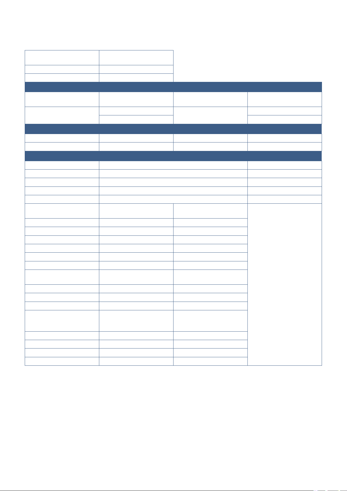
FAT16 (max 2 GB),
FAT32 (max 4 GB)
9
997
JPEG, JPG, JPE Baseline JPEG 75 x 75 pixels 15,360 x 8,640 pixels
Non-interlaced 9,600 x 6,400 pixels
MP3 MPEG1/2 Layer3 (MP3) 320 kbps 2 ch
MPG, MPEG MPEG1, MPEG2, MPEG4 LPCM, MP3, AAC
TS MPEG2, H.264, HEVC/H.265 LPCM, MP3, AAC
MP4 MPEG2, MPEG4, H.263, H.264, HEVC/H.265 LPCM, MP3, AAC
WMV H.264, Windows Media Video 9 WMA 9, WMA 10 Pro
MPEG1 40 Mbps 1920 x 1080 @30 Hz
MPEG2 40 Mbps 1920 x 1080 @30 Hz
MPEG4 40 Mbps 1920 x 1080 @30 Hz
H.263 40 Mbps 1920 x 1080 @30 Hz
H.264 135 Mbps 3840 x 2160 @60 Hz
HEVC/H.265 100 Mbps 3840 x 2160 @60 Hz
Windows Media Video 9
(WMV3)
40 Mbps 1920 x 1080 @30 Hz
LPCM 1.5 Mbps 5.1 ch*
1
MPEG1/2 Layer3 (MP3) 320 kbps 2 ch
AAC AAC-LC: 576 kbps
HE-AAC v1: 288 kbps
HE-AAC v2: 144 kbps
5.1 ch*
1
WMA 9 Standard 320 kbps 2 ch
WMA 10 Pro M0 192 kbps 2 ch
WMA 10 Pro M1 384 kbps 5.1 ch*
1
WMA 10 Pro M2 768 kbps 5.1 ch*
1
*1: It is played with down-converted to 2 ch.
*2: It may not play smoothly with a combination of max bit rate of video and audio.
Sometimes, it may not be possible to play a video le even when the conditions above are met.
The le may not be played properly depending on the bit rate.
Video les made with a codec not supported by the monitor cannot be played.

English - 45
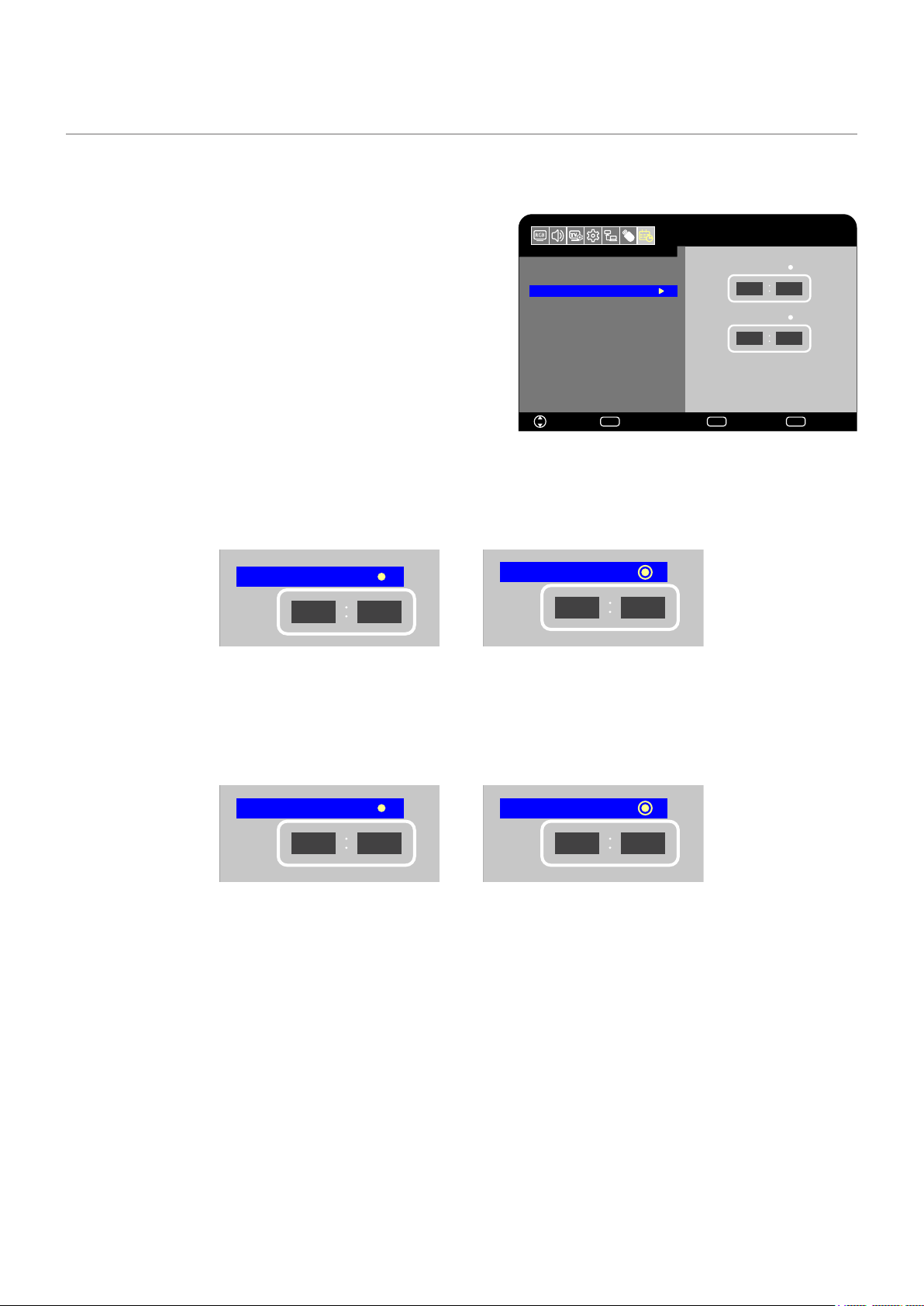
The schedule function allows the monitor to automatically switch between power on and standby mode at different times.
1. Enter the [SCHEDULE] menu in the OSD menu.
a. Use the
p
/
q
buttons of the remote control to select [Current
Time settings].
b Press the OK button of the remote control. Press the
t
,
u
buttons of the remote control to move between the hours and
minutes elds.
c Use the
p
/
q
buttons of the remote control to set the time.
2. After setting the time, press the MENU button of the remote
control.
3. Use the
p
/
q
buttons of the remote control to select [Schedule
settings].
a. Press the OK button of the remote control. Place the cursor on [Power On] and press the OK button of the remote control
to enable the [Power On]. Press the
t
,
u
buttons of the remote control to move between the hours and minutes elds.
Use the
p
/
q
buttons of the remote control to set the time.
Power On
12
00
Power On
Power Off
12
00
Power On disabled Power On enabled
b Use the
t
,
u
buttons of the remote control to place the cursor on [Power Off] and then press the OK button of the remote
control to enable [Power Off]. Press the
t
,
u
buttons of the remote control to move between the hours and minutes
elds.
Use the
p
/
q
buttons of the remote control to set the time.
Power Off
12
00
Power Off
12
00
Power Off disabled Power Off enabled
4. After setting the schedule, press the MENU button of the remote control to return to the previous menu or press the EXIT
button to close the OSD menu.
HDMI1
Schedule
Sleep Timer
Current Time settings
Schedule settings
Power On
Power Off
Move Select
OK
Return
MENU
EXIT
EXIT
12
00
12
00
English - 46
There are different picture modes available. They have been congured for different applications as described in the “Picture
Mode Types” table below.
In the OSD menu, go the [Video] -> [Picture Mode], or press the PICTURE button of the remote control to select a mode.
HDR Video -> Dynamic -> Standard -> Energy Savings -> Conferencing -> HighBright -> Custom
HDR Video Setting for HDR format video (can be selected only when an HDR signal is input)
Dynamic High-contrast video setting
Standard Standard video setting
Energy Savings Video setting complying with the International Energy Star standard.
Conferencing Video setting suited for video conferences
HighBright Video setting suited for brighter environments
Custom Customizable settings

English - 47
Under normal operation, the monitor can be controlled by any person using the remote control or the monitor control panel. You
can prevent unauthorized use and changes to the monitor settings by enabling the security and lock settings.
The security and locking functions covered in this section are:
• Locking the monitor control panel buttons
• Locking the remote control buttons
English - 48
The lock settings prevent the monitor from responding to button presses on the remote control or monitor control panel. When
locking the button controls, some buttons can be congured to remain unlocked. Locking and unlocking the button controls do
not require a password.
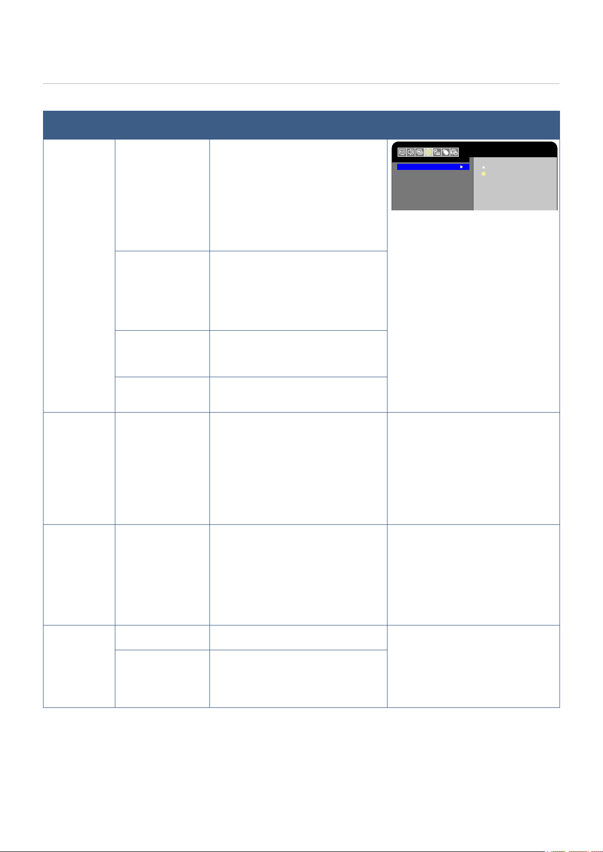
The [Key Lock Settings] prevent the monitor from being controlled using the buttons on the monitor control panel.
Setup
Move Select
Input Labels
Key Lock Settings
IR Lock Settings
Power supply
LED Indicator
Mute Settings
Thermal Management
Signal Information
Off
Mode 1
Mode 2
HDMI1
OK
Return
MENU
EXIT
EXIT
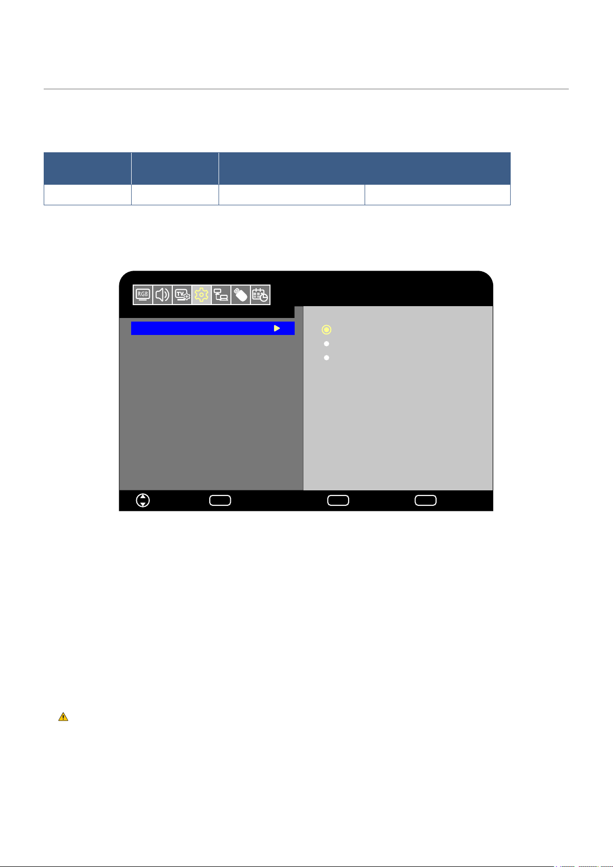
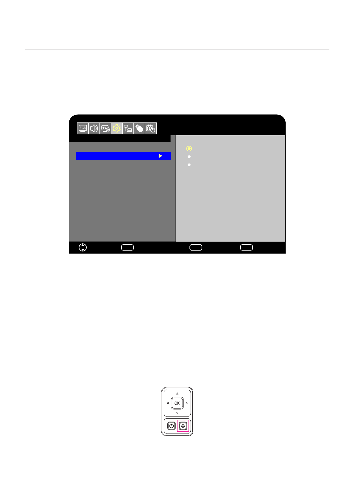
1. In the OSD menu, go to [Setup] -> [Other settings] and select [Key Lock Settings].
2. Select the key lock range.
• All buttons operate normally.
• Only the power button and the input switching function operate.
• All buttons are locked. (Only the power button can be used during standby mode.)
The buttons are locked 3 seconds after Mode1 or Mode2 has been selected.
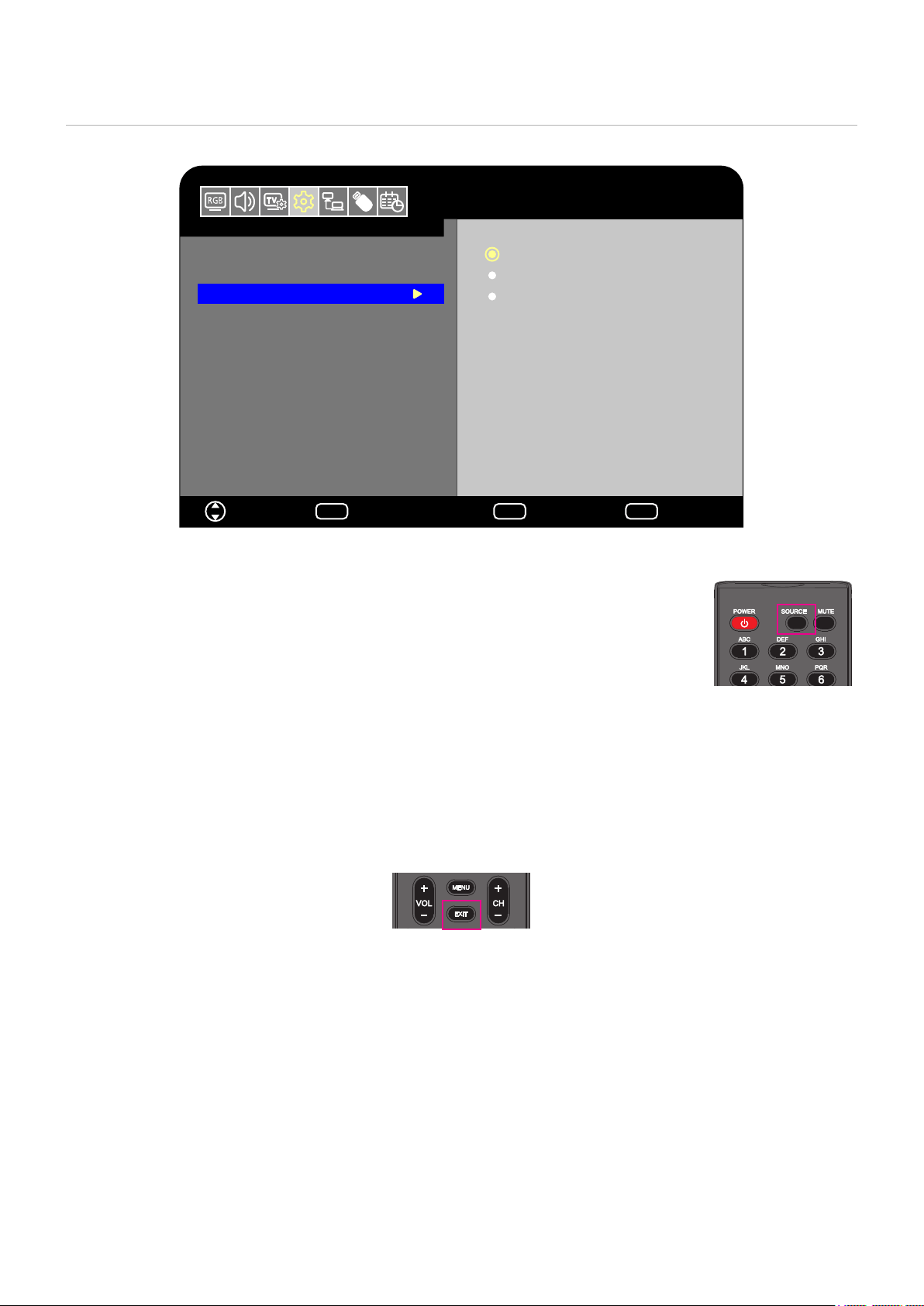
Carry out the following with the monitor in On mode.
•
To remove the lock and restore normal button operation, set the [Key Lock Settings] to [Off] using the remote
control.
•
To remove the lock and restore normal button operation, hold the MENU button pressed for 5 seconds or
more.
English - 49
The [IR Lock Settings] prevent the monitor from being controlled using the remote control.
Setup
Move Select
HDMI1
Input Labels
Key Lock Settings
IR Lock Settings
Power supply
LED Indicator
Mute Settings
Thermal Management
Signal Information
Off
OK
Return
MENU
EXIT
EXIT
Mode 1
Mode 2
1. In the OSD menu, go to [Setup] -> [Other settings] and select [IR Lock Settings].
2. Select the key lock range.
• All buttons operate normally.
• Only the POWER and the SOURCE buttons operate.
• All buttons are locked. (Only the power button can be used during standby mode.)
The buttons are locked 3 seconds after Mode1 or Mode2 has been selected.
Carry out the following with the monitor in On mode.
•
To remove the lock and restore normal button operation, set the [IR Lock Settings] to [Off] using the monitor
buttons.
•
To remove the lock and restore normal button operation, hold the EXIT button pressed for 5 seconds or
more.

English - 50
Chapter 6 External Control
>
"Controlling the Monitor via RS-232C" on page 51
>
"Controlling the Monitor via LAN" on page 52
>
"HTTP Browser" on page 53
>
"Commands" on page 57
There are two options to connect an external device to control the monitor.
• RS-232C Interface
Connecting an external device to the RS-232C terminal of the monitor.
• Network (LAN) Interface
Connecting a network to the LAN port of the monitor with a LAN cable.
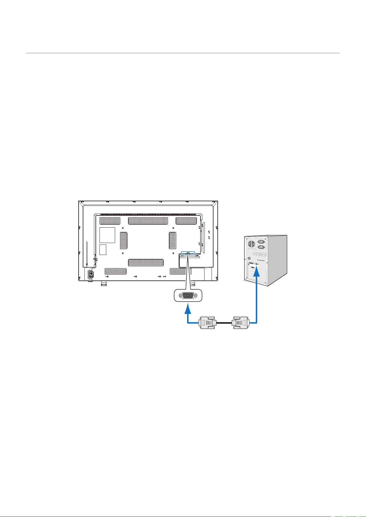
English - 51
This monitor can be controlled by connecting a personal computer with an RS-232C terminal to the RS-232C terminal of the
monitor with a commercially-available RS-232C crossover cable. The following operations are possible.
• Turning the monitor on or putting it into standby.
• Switching between input signals.
• Switching between mute On and Off.
Set [Control Interface] under [Control Settings] to [RS-232C]
(page 81).
Monitor + computer.
• Turn off the monitor and the computer before connecting a computer to the monitor.
• First, turn the computer on, and then turn the monitor on. (Otherwise the COM port may not operate properly.)
• To control the monitor via commands sent from a computer connected with an RS-232C cable, use the control commands.
Instructions for the control commands can be found in “Commands” in “External Control” in this manual or in “External_
Control.pdf” (see “Appendix B External Resources”
page 72).
RS-232C Cable
Computer
RS-232C
• If your computer is equipped only with a 25-pin serial port connector, a 25-pin serial port adapter is required.
Contact your supplier for details.
For the pin assignment, see “Pin Assignment RS-232C input/output”.
This monitor uses RXD, TXD and GND lines for RS-232C control.
A commercially-available crossover cable (not included) should be used for RS-232C control.
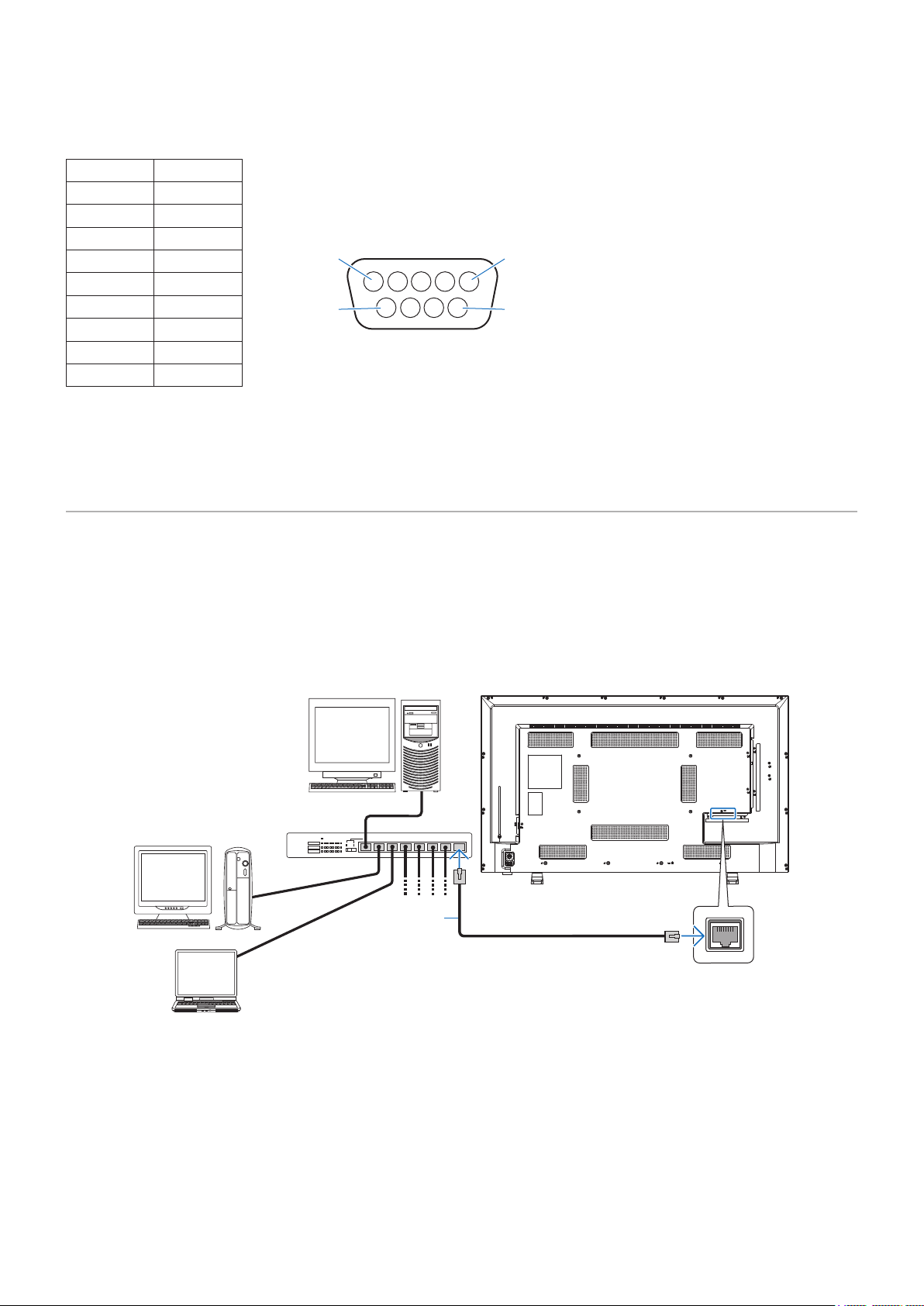
English - 52
RS-232C input / output
Pin No. Name
1 NC
2 RXD
3 TXD
4 NC
5 GND
6 NC
7 NC
8 NC
9 NC
This monitor uses RXD, TXD and GND lines for RS-232C control.
The monitor is equipped with a LAN port (RJ-45). Connecting the monitor to a network allows you to receive email notications
from the monitor and control the monitor from a computer via a network. To use a LAN connection, you are required to assign an
IP address to the monitor (page 81).
The monitor will obtain an IP address automatically when connected to a DHCP network.
Set [Control Interface] under [Control Settings] to [LAN]
(page 81).
Server
Hub
NOTE: Use a category 5 or higher LAN cable.
LAN cable
(commercially available)
D-sub 9-pin (monitor side)
1
6
5
9

English - 53
Connect the monitor with a commercially-available LAN cable to congure the LAN settings using the HTTP server function.
This monitor uses “JavaScript” and “Cookies” and the browser should be set to accept these functions. Refer to the help les for
the Web browser to change the settings to use JavaScript and Cookies.
To access the HTTP server, launch a web browser on a computer connected to the same network as the monitor and enter the
following URL in the Web address eld.
http://<Address IP of the monitor>
• The control software can be downloaded from the NEC Display website.
By default, the IP address of the monitor is set automatically. After a reset, the IP address is obtained
automatically.
Depending on the network environment, the display speed and response to commands or clicks on buttons may
be slow, or the operations may not be recognized. In such a case, consult your network administrator.
The monitor may not respond if the buttons shown on the browser are repeatedly pressed in rapid intervals. In
such a case, wait a moment and try again. If you still can’t get a response, turn the monitor off and then back on.
If the monitor Network Settings screen does not appear in the Web browser, press the Ctrl+F5 keys to refresh
your Web browser.
To control the monitor via a LAN, see “External_Control.pdf” in our Website (see “Appendix B External
Resources”
page 72). If the screen does not appear, clear the cache of the Web browser.
Connect the monitor to the network using a commercially-available LAN cable before attempting to use browser operations.
Operation with a browser that uses a proxy server may not be possible depending on the type of proxy server and the setting
method. Although the type of the proxy server will be a factor, it is possible that items that have been set will not be shown
depending on the effectiveness of the cache, and the settings congured from the browser may not be reected in operation. It
is recommended that a proxy server is not used unless the network environment requires it.
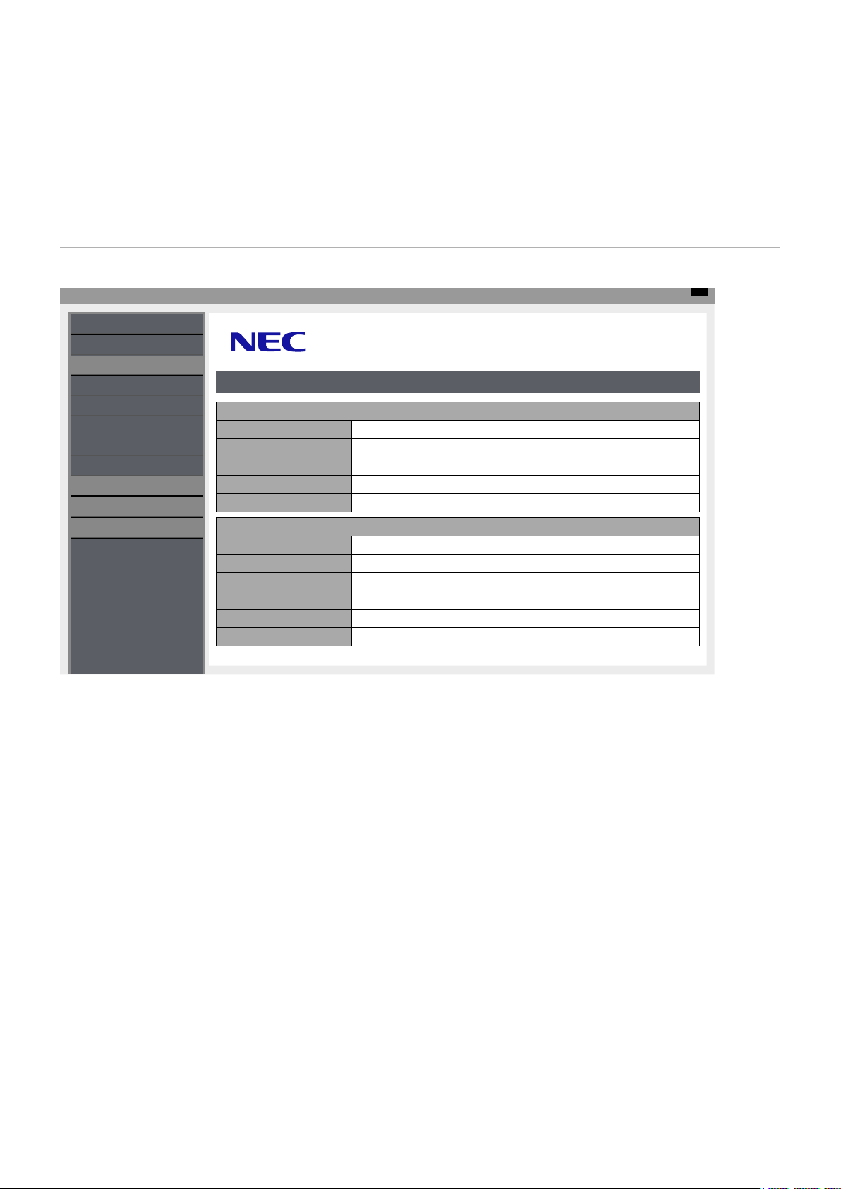
English - 54
Access the following address to show HOME. Click the links on the left-hand column on the HOME screen to access the setting
screens.
http://<Address IP of the monitor>
The default login password is “admin”.
The functions related to the network can be congured the same way as in the OSD menu using the links below.
Top
INPUT SOURCE: HDMI1
STATUS
PROTOCOL
STATUS
SYSTEM
MODEL NAME E438
SERIAL XX3XXXXXXX
FIRMWARE VERSION Vx.x.x / Vx.x.x
LOCAL TIME WWW MMM DD XX:XX:XX 20YY
UPTIME XXh XXm XXs
NETWORK
IP ADDRESS 192.168.0.10
SUBNET MASK 255.255.255.0
DEFAULT GATEWAY 0.0.0.0
DNS PRIMARY 0.0.0.0
DNS SECONDARY 0.0.0.0
MAC Address XX:XX:XX:XX:XX:XX
NETWORK
SYSTEM
LOGOUT
TCP
ROOMVIEW
CRESTRON CONTROL
AMX
NAME
OVERVIEW
The Crestron functions are only available on monitors that have a serial number with a third-digit of "3" or
higher (xx3xxxxxxx).
You can check the monitor's serial number at [Setup]->[Monitor Information]->[SN:].
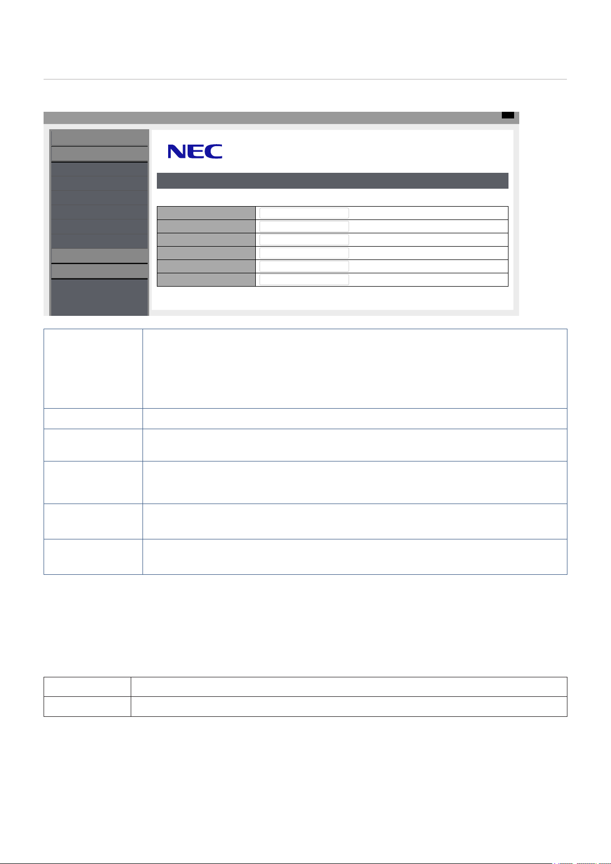
English - 55
Click on “NETWORK” on the left-hand column on the HOME screen to enter the setting screen.
Top
INPUT SOURCE: HDMI1
STATUS
PROTOCOL
NETWORK SETTINGS
DHCP
INTERFACE
IP ADDRESS
192.168.0.10
Off
SUBNET MASK 255.255.255.0
DEFAULT GATEWAY 0.0.0.0
DNS PRIMARY 0.0.0.0
DNS SECONDARY 0.0.0.0
NETWORK
SYSTEM
LOGOUT
TCP
ROOMVIEW
CRESTRON CONTROL
AMX
NAME
DHCP Select a method for setting the IP ADDRESS.
Off: Sets xed network settings.
On: Obtains the network settings from the DHCP server on the network.
Manual DNS: Obtains the network settings from the DHCP server on the network but the DNS
is set manually.
Consult your network administrator if you have any trouble with the connection.
IP ADDRESS Set the IP address for the monitor connected to the network when [Off] is selected for [DHCP].
SUBNET MASK Set the subnet mask for the network to which the monitor is connected when [Off] is selected for
[DHCP].
DEFAULT GATEWAY Set the default gateway for the network to which the monitor is connected when [Off] is selected for
[DHCP].
Enter [0.0.0.0] to delete the setting.
DNS PRIMARY Enter the IP address of the primary DNS server of the network connected to the monitor.
Enter [0.0.0.0] to delete the setting.
DNS SECONDARY Enter the IP address of the secondary DNS server of the network connected to the monitor.
Enter [0.0.0.0] to delete the setting.
Click on “ROOMVIEW” on the left column below HOME.
The monitor supports Crestron’s ROOMVIEW, allowing multiple devices connected in the network to be managed and controlled
from a computer or a controller.
ROOMVIEW
Enables or Disables managing from the computer.
PORT Sets the Crestron port used for Ethernet communication.
For further information, visit http://www.crestron.com
English - 56
Click on “CRESTRON CONTROL” on the left column below HOME.
CRESTRON CONTROL
Enables or Disables managing from the controller.
CONTROLLER IP ADDRESS Sets the IP address of the CRESTRON SERVER.
IP ID Sets your CRESTRON SERVER IP ID.
PORT Sets the Crestron port used for Ethernet communication.
The CRESTRON CONTROL settings are required only for use with Crestron’s ROOMVIEW.
For further information, visit
http://www.crestron.com
Click on “AMX” on the left-hand column on the HOME screen to enter the setting screen.
AMX BEACON
When the monitor is connected to a network supporting the NetLinx control system by AMX, enables or
disables the function to send a beacon to the system from AMX Device Discovery.
When using a device that supports AMX Device Discovery, all AMX NetLinx control systems will recognize the
device and download the appropriate Device Discovery Module from an AMX server.
English - 57
Connecting the monitor to a computer via RS-232C or to a network via LAN allows for the transmission of commands to the
monitor, providing remote control of the monitor from a connected device. Instructions for each command format can be found in
“External_Control.pdf” in our Website (see “Appendix B External Resources”
page 72).
PROTOCOL RS-232C
BAUD RATE 9600 [bps]
DATA LENGTH 8 [bits]
PARITY NONE
STOP BIT 1 [bit]
FLOW CONTROL NONE
PROTOCOL TCP
PORT NUMBER 7142
COMMUNICATION SPEED AUTO setting (10/100Mbps)

English - 58
Chapter 7 Troubleshooting
>
"When a problem occurs with the monitor���" on page 59
>
"Nothing is displayed���" on page 59
>
"The image is not displayed correctly���" on page 60
>
"An instruction or caution screen is displayed���" on page 61
>
"Others (when connected to a computer)" on page 61
>
"Others (remote control, speakers)" on page 61
>
"Others (when connected via RS-232C or LAN)" on page 62
>
"When using a media player" on page 62
>
"When using a video device" on page 62
English - 59
In such a case, refer to the following.
The power indicator is off
In the OSD menu, [Setup]
-> [Other Settings] -> [LED
Indicator] is set to [On]
Check that the power cord is properly connected.
P.12
Use another device to check that power is correctly supplied
to the outlet.
The power indicator is lit
blue
A terminal to which no signal is input may be selected. Press
the input switch button to select a different input terminal.
P.22
Display the OSD menu and check the following settings. P.39
● If the OSD menu does not appear, the monitor may
malfunction.
Contact your supplier.
● If the OSD menu is displayed properly, the monitor is
not malfunctioning. Adjust [Backlight / Brightness] and
[Contrast] in the [Video] settings.
P.75
● If the image is not displayed after adjusting [Backlight /
Brightness] and [Contrast] in the OSD menu, check that
the connected device operates correctly. If the monitor is
connected to a computer, check the frequency, resolution,
and type of output signal on the computer.
P.27
The power indicator is lit
a color other than blue or
is ashing.
The power management function may be functioning. Press
any button on the keyboard, move the mouse, or press the
POWER button on the power cable or the remote control.
P.24,
P.34
Check that the signal cable is correctly connected to the
input and output terminals of the monitor and the connected
device.
P.26
Check that the power adaptor is properly connected. P.27
Check that the connected computer or video device is turned
on.
The screen, on which
the image was correctly
displayed, turned black,
started to blink, or did not
display anything.*
The LCD panel needs to be replaced. Contact your supplier.
* The lifespan of the backlight used in the monitor may end.
English - 60
This is due to the characteristics of LCD panels and is not a malfunction.
This may happen depending on the content displayed. This is due to the
characteristics of LCD panels and is not a malfunction.
This may happen depending on the content displayed. This is due to the
characteristics of LCD panels and is not a malfunction.
This may happen when detailed patterns are displayed. This is due to the
characteristics of LCD panels and is not a malfunction.
The tint may greatly vary depending on the viewing angle (the angle from
which the screen is viewed).
P.66-
69
The display condition changes gradually while the monitor is being used. The
ambient temperature may also have an impact on the display condition.
This is due to the characteristics of LCD panels and is not a malfunction.
P.24
When the same still image is displayed for a long time, this phenomenon of
persisting image may occur.
You may press the POWER button of the remote control or the
of the
monitor to put the monitor on standby, or display changing images for about
one day until the persisting image disappears naturally.
If the still image is
displayed for a really long time, the persisting image may not disappear. This
is not a malfunction. It is recommended to turn the monitor off when not using
it.
Display the OSD menu and check the following settings. P.39
● If the OSD menu is not displayed properly, the monitor may malfunction.
Contact your supplier.
● If the OSD menu is displayed properly, the monitor is not malfunctioning.
Select [Color] and adjust the colors as needed, or execute [Reset Video
Settings] under the [Video] settings to return the settings to their default
values.
P.75,
P.75
● If the OSD menu is displayed properly and the computer screen does not
appear correctly after executing [Reset Video Settings] under [Video],
check the connection to the computer as well as the frequency, resolution
and output signal type setting on the computer.
P.26,
P.64
The image quality may decrease or the video may be interrupted if a
transponder, a splitter, or a long cable is used. Replace the cable you are
using with a shielded cable, or connect directly to the monitor without using
a transponder or a splitter. If a twisted pair cable extender is used, make
sure it supports shielded cables. Noise may also appear on the screen or
the video may be interrupted depending on the usage environment and the
cable used.
In such a case, see the “Precautions regarding display installation and
connection” in the NEC Display Solutions Website.
Display the OSD menu and check the following settings.
P.39
● If the OSD menu is not displayed properly, the monitor may malfunction.
Contact your supplier.
● If the video is interrupted when an HDMI signal with the 3840 x 2160 or
4096 x 2160 resolution is input, use an HDMI cable supporting 4K.
Check the setting in [Setup] -> [Power save settings] -> [Auto Power Down].
Set the [CEC] setting under [Setup] -> [HDMI Settings] to [Off].
Check the setting in [Schedule] -> [Sleep Timer].
P.78,
P.83
Check the setting in [Schedule] -> [Current Time settings].
Enable [Power On] under [Schedule] -> [Schedule settings].
Enable [Power Off] under [Schedule] -> [Schedule settings].
P.83
The display may be disturbed when power is turned on or when the settings
have been changed. This is not a malfunction.
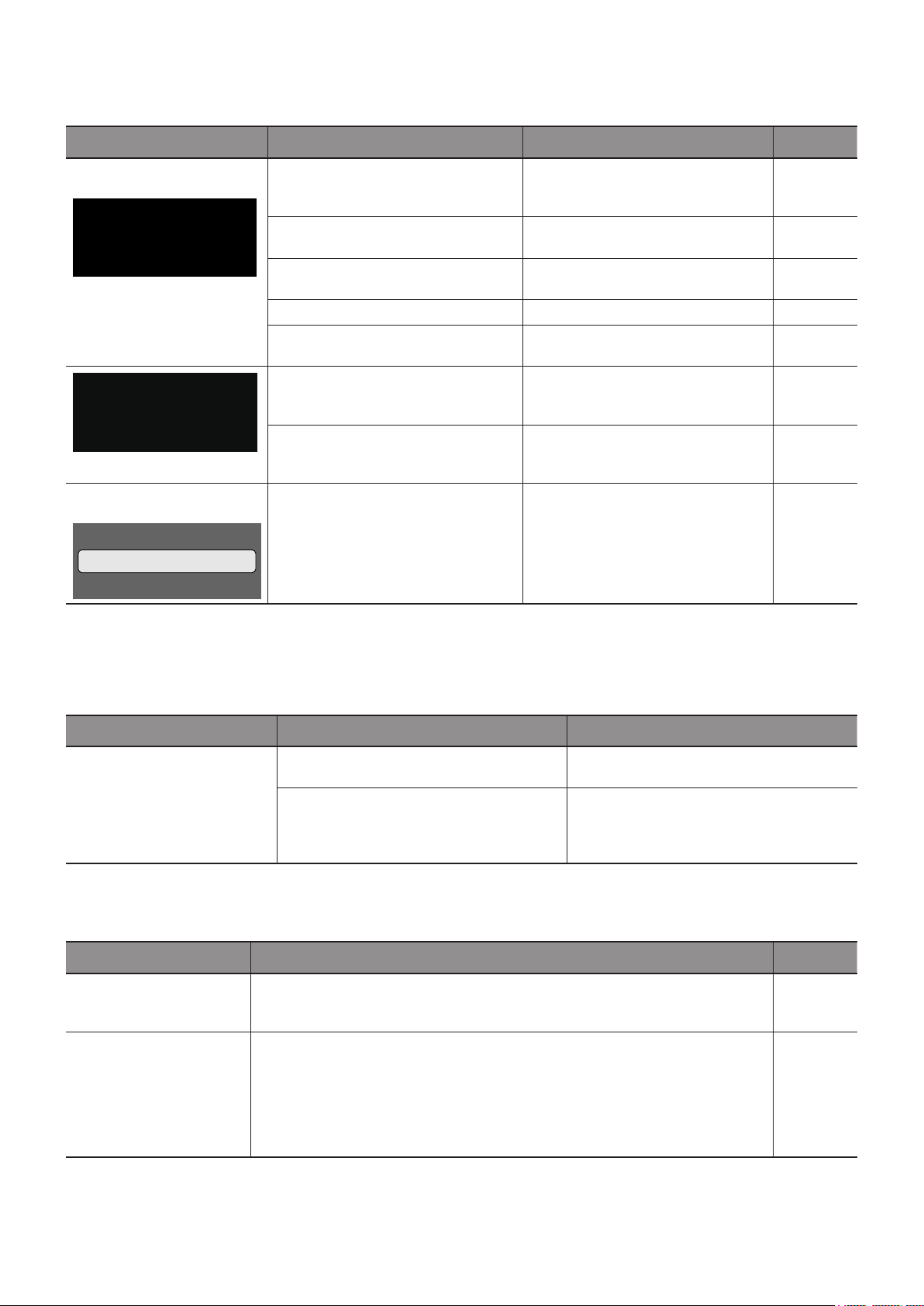
English - 61
Attention !
No Signal
Please check input signal or Connection.
The signal cable may not be connected
properly to the input or output terminals
of the monitor or the computer.
Connect properly the signal cable to
the input and output terminals of the
monitor and the computer.
P.26
The HDMI input may have switched. Set the [CEC] setting under [Setup] ->
[HDMI Settings] to [Off].
P.79
The signal cable may be damaged. Check that the signal cable is not
damaged.
The computer may be turned off. Check that the computer is turned on.
The power management function of
the computer may be functioning.
Move the mouse or press a key on the
keyboard.
Out of Range
An improper signal may be input to the
monitor.
Change the frequency of the input
signal or the resolution of the
computer.
P.64
A signal with a resolution higher than
the resolution supported by the monitor
may be input.
Change the frequency of the input
signal or the resolution of the
computer.
P.64
Warning!!
The internal temperature is high.
Please check the ambient temperature.
The ambient temperature exceeds the
operation guaranteed temperature.
Turn off the power of the monitor since
this problem may cause a malfunction.
P.80
*1 Depending on the computer, a proper signal may not be output immediately after changing the resolution or the frequency and the caution
may be displayed for a while. In such a case, wait for a while. If the screen display returns to normal, it means the input signal is proper.
Sometimes, the signal cannot be input and
output.
Restart the monitor and the computer.
The driver of the video card may not be
correctly recognized by the OS.
Reinstall the video card driver. For more
information on the reinstallation procedure,
refer to the computer manual or the support
service for the computer.
● The batteries may be at.
● Check that the batteries are inserted correctly (check the + and - sides).
● The [IR Lock Settings] may be set to [Mode 1] or [Mode 2].
P.11,
P.80
● Check that the audio cable is correctly connected. Check also that the audio
balance is not fully set to one side only. If the balance is set to one side only, set
it to the center.
● The sound may be muted. Press the MUTE button on the remote control or the
main unit and check that the sound is output.
● The volume may be set to the minimum. Adjust the volume using the + and -
buttons on the main unit or the VOL + and - buttons on the remote control.
P.23,
P.24,
P.76
English - 62
Check that the RS-232C crossover cable is correctly connected. P.51
Check that the LAN cable (Cat.5 or higher) is correctly connected. P.52
Check that the Network Settings are correctly congured. P.52
Check that a USB storage device is correctly connected to the USB port. P.31
Check that the external device (video player, etc.) is correctly connected and
operates properly. For more information, see the manual of the external device.
P.26
The power management function of the monitor may be functioning. Check that
the external device is operating (playing).
Adjust the [Color] setting.
P.75

English - 64
640 x 480p 60 ● ●
720 x 480i 60 ● ●
720 x 480p 60 ● ●
720 x 576i 50 ● ●
720 x 576p 50 ● ●
1280 x 720p 50 ● ●
1280 x 720p 60 ● ●
1920 x 1080i
50
● ●
60
24
25
1920 x 1080p 30 ● ●
50
60
24 — — ● ● ● ●
25 — — ● ● ● ●
3840 x 2160p 30 — — ● ● ● ●
50 — — ● ● ● ●
60 — — ● ● ● ●
24 — — ● ● ● ●
25 — — ● ● ● ●
4096 x 2160p 30 — — ● ● ● ●
50 — — ● ● ● ●
60 — — ● ● ● ●

English - 65
720 x 400 70 ● ●
640 x 480 60 ● ●
800 x 600
56 ● ●
60 ● ●
1024 x 768 60 ● ●
1280 x 720 60 ● ●
1280 x 800 60 ● ●
1280 x 960 60 ● ●
1280 x 1024
60 ● ●
75 ● ●
1400 x 1050 60 (RB*) ● ●
1440 x 900 60 ● ●
1600 x 1200 60 ● ●
1680 x 1050 60 ● ●
1920 x 1080 60 ● ●
3840 x 2160
30 — — ● ● ● ●
60 — — ● ● ● ●
1366 x 768 60 — ● ● ● ● ●
1920 x 1440 60 — — ● ● ● ●
2560 x 1600 60 — — ● ● ● ●
* RB: Reduced blanking signal
• Depending on the input signal’s resolution, characters may look blurred or gures may be distorted.
Depending on the video card or driver used, the image may not be shown correctly.
English - 66
Size (display size) 32”/801.3 mm diagonal
Type of LCD Active Matrix Color TFT LCD
Viewable Size 698.40 x 392.85 mm
Resolution 1920 x 1080
Pixel Pitch 0.364 mm
Color Approx. 16.77 million colors (depends on the video card)
Brightness 350 cd/m
2
(Max.) (@25 °C)
Frequency
Horizontal
31 - 83 kHz (analog input)
15.625/15.734 kHz, 31 - 136 kHz (digital input)
Vertical
56 Hz, 60 Hz, 70 Hz, 75 Hz (analog input)
24 Hz, 30 Hz, 50 Hz, 60 Hz, 70 Hz, 75 Hz (digital input)
Pixel Clock
13.5 MHz, 25 MHz - 156 MHz (analog input)
25 MHz - 600 MHz (digital input)
Input
Terminals
TV RF terminal ATSC, NTSC VHF/UHF Antenna or Cable TV Service
VGA (RGB)
*2
15 Pin D-sub Analog RGB signal 0.7 Vp-p/75 Ω
VGA (YPbPr)
*2
15 Pin D-sub Component signal Luma Y: 1.0 Vp-p/75 Ω, Color Cb/Cr (Pb/Pr): 0.7 Vp-p/75 Ω
Video 3.5φ Mini Jack Composite signal 1.0 Vp-p/75 Ω
HDMI HDMI terminal
Digital YUV
Digital RGB
HDCP 1.4/2.2
Audio
Terminals
Audio input
Stereo Mini Jack 3.5 mm Ø Analog audio signal Stereo L/R 0.5 Vrms
HDMI terminal Digital audio signal PCM 2 ch 32, 44.1, 48 kHz (16/20/24 bits)
Audio output
Stereo Mini Jack 3.5 mm Ø Analog audio signal For headphones output
S/PDIF terminal Digital audio signal For digital audio output
HDMI (ARC) terminal
*3
Digital audio signal PCM 2 ch 32, 44.1, 48 kHz (16/20/24 bits)
Speaker
Output
Internal Speakers 5 W + 5 W (Stereo)
Control
Terminals
RS-232C 9 Pin D-sub x1
LAN RJ-45 10BASE-T / 100BASE-TX
USB Terminal
USB Type-A port For media player, DC 5 V
/ 500 mA (max)
USB Type-C port For power supply, DC 5 V / 3 A (max)
Operational
Environment
Temperature 0 - 40 °C / 32 - 104 °F
Humidity 20 - 80 % (without condensation)
Altitude 0 - 3000 m
Storage
Environment
Temperature –20 - 60 °C / –4 - 140 °F
Humidity 10 - 80 % (without condensation)
Power Supply
Power input AC 120 - 127 V 50/60Hz
Input current 0.8 A
Consumption
Full operation 80 W
During power save 2.0 W or less
*1
During standby 0.5 W or less
*1
Weight
With the stand Approx. 5.9 kg (13 lbs)
Without the stand Approx. 5.7 kg (12.5 lbs)
Inclination Angle ±10°
Dimensions
*1 When used with the default
settings.
*2 Common terminal.
*3 HDMI1 only.
726.6
67.1
40.5
196.0
422.4
Technical specications are subject to change without notice. Unit: mm
English - 67
Size (display size) 43”/1080 mm diagonal
Type of LCD Active Matrix Color TFT LCD
Viewable Size 941.18 x 529.42 mm
Resolution 3840 x 2160
Pixel Pitch 0.245 mm
Color Over 1073 million colors
Brightness 350 cd/m
2
(Max.) (@25 °C)
Frequency
Horizontal
31 - 83 kHz (analog input)
15.625/15.734 kHz, 31 - 136 kHz (digital input)
Vertical
56 Hz, 60 Hz, 70 Hz, 75 Hz (analog input)
24 Hz, 30 Hz, 50 Hz, 60 Hz, 70 Hz, 75 Hz (digital input)
Pixel Clock
13.5 MHz, 25 MHz - 162 MHz (analog input)
25 MHz - 600 MHz (digital input)
Input
Terminals
TV RF terminal ATSC, NTSC VHF/UHF Antenna or Cable TV Service
VGA (RGB)
*2
15 Pin D-sub Analog RGB signal 0.7 Vp-p/75 Ω
VGA (YPbPr)
*2
15 Pin D-sub Component signal Luma Y: 1.0 Vp-p/75 Ω, Color Cb/Cr (Pb/Pr): 0.7 Vp-p/75 Ω
Video 3.5φ Mini Jack Composite signal 1.0 Vp-p/75 Ω
HDMI HDMI terminal
Digital YUV
Digital RGB
HDCP 1.4/2.2
Audio
Terminals
Audio input
Stereo Mini Jack 3.5 mm Ø Analog audio signal Stereo L/R 0.5 Vrms
HDMI terminal Digital audio signal PCM 2 ch 32, 44.1, 48 kHz (16/20/24 bits)
Audio output
Stereo Mini Jack 3.5 mm Ø Analog audio signal For headphones output
S/PDIF terminal Digital audio signal For digital audio output
HDMI (ARC) terminal
*3
Digital audio signal PCM 2 ch 32, 44.1, 48 kHz (16/20/24 bits)
Speaker
Output
Internal Speakers 10 W + 10 W (Stereo)
Control
Terminals
RS-232C 9 Pin D-sub x1
LAN RJ-45 10BASE-T / 100BASE-TX
USB Terminal
USB Type-A port For media player, DC 5 V / 500 mA (max)
USB Type-C port For power supply, DC 5 V / 3 A (max)
Operational
Environment
Temperature 0 - 40 °C / 32 - 104 °F
Humidity 20 - 80 % (without condensation)
Altitude 0 - 3000 m
Storage
Environment
Temperature –20 - 60 °C / –4 - 140 °F
Humidity 10 - 80 % (without condensation)
Power Supply
Power input AC 120 - 127 V 50/60Hz
Input current 1.3 A
Consumption
Full operation 130 W
During power save 2.0 W or less
*1
During standby 0.5 W or less
*1
Weight
With the stand Approx. 10.4 kg (22.9 lbs)
Without the stand Approx. 10.2 kg (22.4 lbs)
Inclination Angle ±10°
Dimensions
*1 When used with the default
settings.
*2 Common terminal.
*3 HDMI1 only.
970.2
71.0
43.3
196
559.8
Technical specications are subject to change without notice. Unit: mm
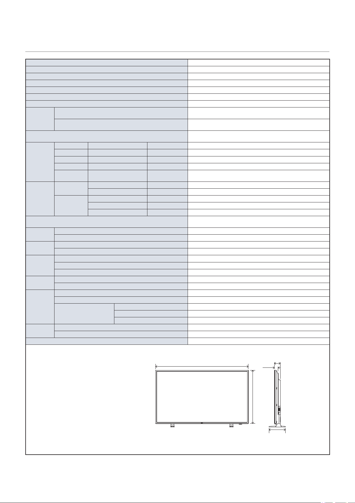
English - 68
Size (display size) 49”/1232 mm diagonal
Type of LCD Active Matrix Color TFT LCD
Viewable Size 1073.80 x 604.00 mm
Resolution 3840 x 2160
Pixel Pitch 0.280 mm
Color Over 1073 million colors
Brightness 350 cd/m
2
(Max.) (@25 °C)
Frequency
Horizontal
31 - 83 kHz (analog input)
15.625/15.734 kHz, 31 - 136 kHz (digital input)
Vertical
56 Hz, 60 Hz, 70 Hz, 75 Hz (analog input)
24 Hz, 30 Hz, 50 Hz, 60 Hz, 70 Hz, 75 Hz (digital input)
Pixel Clock
13.5 MHz, 25 MHz - 162 MHz (analog input)
25 MHz - 600 MHz (digital input)
Input
Terminals
TV RF terminal ATSC, NTSC VHF/UHF Antenna or Cable TV Service
VGA (RGB)
*2
15 Pin D-sub Analog RGB signal 0.7 Vp-p/75 Ω
VGA (YPbPr)
*2
15 Pin D-sub Component signal Luma Y: 1.0 Vp-p/75 Ω, Color Cb/Cr (Pb/Pr): 0.7 Vp-p/75 Ω
Video 3.5φ Mini Jack Composite signal 1.0 Vp-p/75 Ω
HDMI HDMI terminal
Digital YUV
Digital RGB
HDCP 1.4/2.2
Audio
Terminals
Audio input
Stereo Mini Jack 3.5 mm Ø Analog audio signal Stereo L/R 0.5 Vrms
HDMI terminal Digital audio signal PCM 2 ch 32, 44.1, 48 kHz (16/20/24 bits)
Audio output
Stereo Mini Jack 3.5 mm Ø Analog audio signal For headphones output
S/PDIF terminal Digital audio signal For digital audio output
HDMI (ARC) terminal
*3
Digital audio signal PCM 2 ch 32, 44.1, 48 kHz (16/20/24 bits)
Speaker
Output
Internal Speakers 10 W + 10 W (Stereo)
Control
Terminals
RS-232C 9 Pin D-sub x1
LAN RJ-45 10BASE-T / 100BASE-TX
USB Terminal
USB Type-A port For media player, DC 5 V / 500 mA (max)
USB Type-C port For power supply, DC 5 V / 3 A (max)
Operational
Environment
Temperature 0 - 40 °C / 32 - 104 °F
Humidity 20 - 80 % (without condensation)
Altitude 0 - 3000 m
Storage
Environment
Temperature –20 - 60 °C / –4 - 140 °F
Humidity 10 - 80 % (without condensation)
Power Supply
Power input AC 120 - 127 V 50/60Hz
Input current 1.8 A
Consumption
Full operation 180 W
During power save 2.0 W or less
*1
During standby 0.5 W or less
*1
Weight
With the stand Approx. 12.4 kg (27.3 lbs)
Without the stand Approx. 12.1 kg (26.7 lbs)
Inclination Angle ±10°
Dimensions
*1 When used with the default
settings.
*2 Common terminal.
*3 HDMI1 only.
1102.8
71.6
44.3
196
634.4
Technical specications are subject to change without notice. Unit: mm
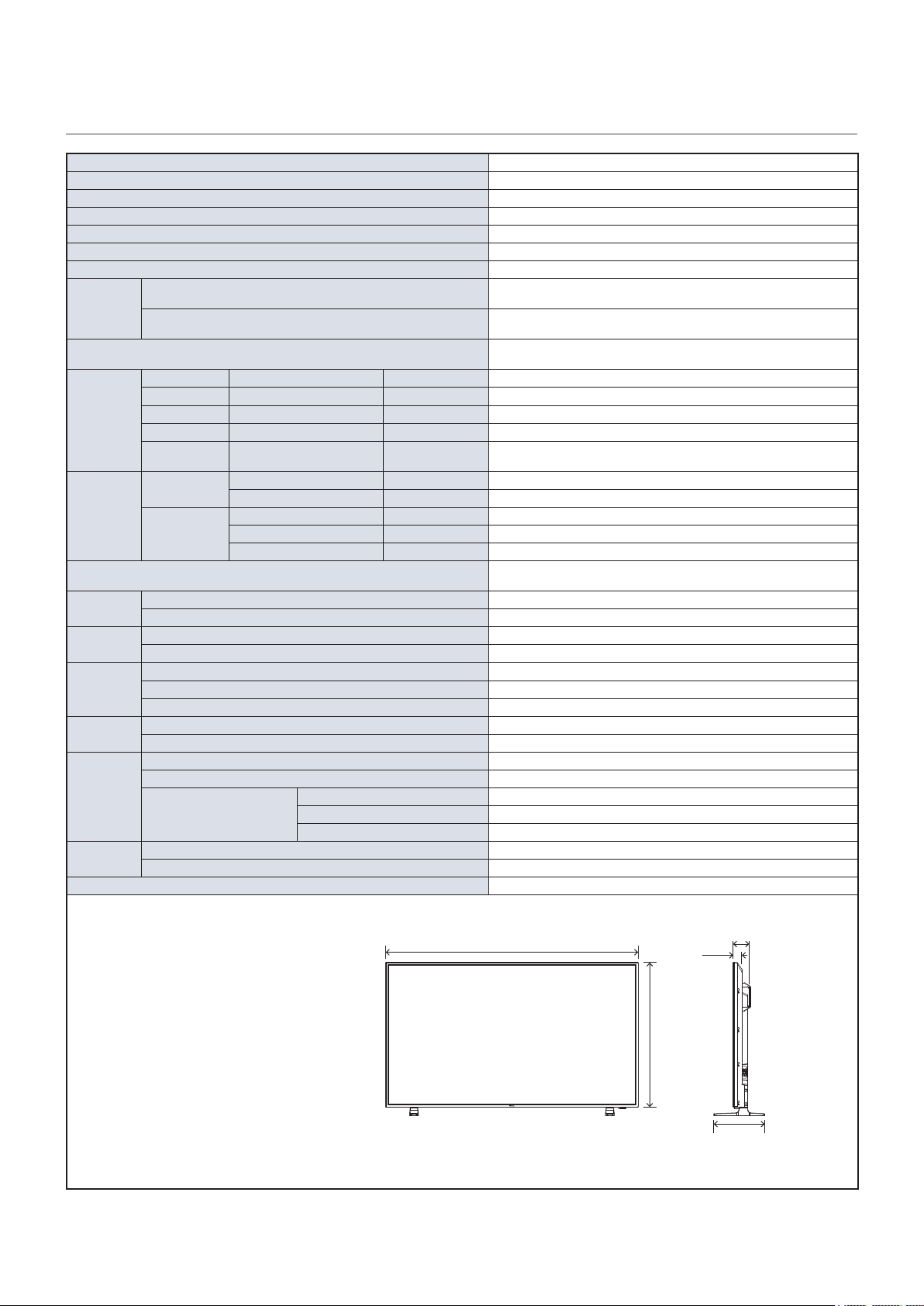
English - 69
Size (display size) 55”/1388 mm diagonal
Type of LCD Active Matrix Color TFT LCD
Viewable Size 1209.60 x 680.40 mm
Resolution 3840 x 2160
Pixel Pitch 0.315 mm
Color Over 1073 million colors
Brightness 350 cd/m
2
(Max.) (@25 °C)
Frequency
Horizontal
31 - 83 kHz (analog input)
15.625/15.734 kHz, 31 - 136 kHz (digital input)
Vertical
56 Hz, 60 Hz, 70 Hz, 75 Hz (analog input)
24 Hz, 30 Hz, 50 Hz, 60 Hz, 70 Hz, 75 Hz (digital input)
Pixel Clock
13.5 MHz, 25 MHz - 162 MHz (analog input)
25 MHz - 600 MHz (digital input)
Input
Terminals
TV RF terminal ATSC, NTSC VHF/UHF Antenna or Cable TV Service
VGA (RGB)
*2
15 Pin D-sub Analog RGB signal 0.7 Vp-p/75 Ω
VGA (YPbPr)
*2
15 Pin D-sub Component signal Luma Y: 1.0 Vp-p/75 Ω, Color Cb/Cr (Pb/Pr): 0.7 Vp-p/75 Ω
Video 3.5φ Mini Jack Composite signal 1.0 Vp-p/75 Ω
HDMI HDMI terminal
Digital YUV
Digital RGB
HDCP 1.4/2.2
Audio
Terminals
Audio input
Stereo Mini Jack 3.5 mm Ø Analog audio signal Stereo L/R 0.5 Vrms
HDMI terminal Digital audio signal PCM 2 ch 32, 44.1, 48 kHz (16/20/24 bits)
Audio output
Stereo Mini Jack 3.5 mm Ø Analog audio signal For headphones output
S/PDIF terminal Digital audio signal For digital audio output
HDMI (ARC) terminal
*3
Digital audio signal PCM 2 ch 32, 44.1, 48 kHz (16/20/24 bits)
Speaker
Output
Internal Speakers 10 W + 10 W (Stereo)
Control
Terminals
RS-232C 9 Pin D-sub x1
LAN RJ-45 10BASE-T / 100BASE-TX
USB Terminal
USB Type-A port For media player, DC 5 V / 500 mA (max)
USB Type-C port For power supply, DC 5 V / 3 A (max)
Operational
Environment
Temperature 0 - 40 °C / 32 - 104 °F
Humidity 20 - 80 % (without condensation)
Altitude 0 - 3000 m
Storage
Environment
Temperature –20 - 60 °C / –4 - 140 °F
Humidity 10 - 80 % (without condensation)
Power Supply
Power input AC 120 - 127 V 50/60Hz
Input current 1.8 A
Consumption
Full operation 180 W
During power save 2.0 W or less
*1
During standby 0.5 W or less
*1
Weight
With the stand Approx. 17.1 kg (37.7 lbs)
Without the stand Approx. 16.8 kg (37.0 lbs)
Inclination Angle ±10°
Dimensions
*1 When used with the default
settings.
*2 Common terminal.
*3 HDMI1 only.
1238.6
72.0
44.3
250
710.8
Technical specications are subject to change without notice. Unit: mm

English - 70
Size (display size) 65”/1639 mm diagonal
Type of LCD Active Matrix Color TFT LCD
Viewable Size 1428.48 x 803.52 mm
Resolution 3840 x 2160
Pixel Pitch 0.372 mm
Color Over 1073 million colors
Brightness 350 cd/m
2
(Max.) (@25 °C)
Frequency
Horizontal
31 - 83 kHz (analog input)
15.625/15.734 kHz, 31 - 136 kHz (digital input)
Vertical
56 Hz, 60 Hz, 70 Hz, 75 Hz (analog input)
24 Hz, 30 Hz, 50 Hz, 60 Hz, 70 Hz, 75 Hz (digital input)
Pixel Clock
13.5 MHz, 25 MHz - 162 MHz (analog input)
25 MHz - 600 MHz (digital input)
Input
Terminals
TV RF terminal ATSC, NTSC VHF/UHF Antenna or Cable TV Service
VGA (RGB)
*2
15 Pin D-sub Analog RGB signal 0.7 Vp-p/75 Ω
VGA (YPbPr)
*2
15 Pin D-sub Component signal Luma Y: 1.0 Vp-p/75 Ω, Color Cb/Cr (Pb/Pr): 0.7 Vp-p/75 Ω
Video 3.5φ Mini Jack Composite signal 1.0 Vp-p/75 Ω
HDMI HDMI terminal
Digital YUV
Digital RGB
HDCP 1.4/2.2
Audio
Terminals
Audio input
Stereo Mini Jack 3.5 mm Ø Analog audio signal Stereo L/R 0.5 Vrms
HDMI terminal Digital audio signal PCM 2 ch 32, 44.1, 48 kHz (16/20/24 bits)
Audio output
Stereo Mini Jack 3.5 mm Ø Analog audio signal For headphones output
S/PDIF terminal Digital audio signal For digital audio output
HDMI (ARC) terminal
*3
Digital audio signal PCM 2 ch 32, 44.1, 48 kHz (16/20/24 bits)
Speaker
Output
Internal Speakers 10 W + 10 W (Stereo)
Control
Terminals
RS-232C 9 Pin D-sub x1
LAN RJ-45 10BASE-T / 100BASE-TX
USB Terminal
USB Type-A port For media player, DC 5 V / 500 mA (max)
USB Type-C port For power supply, DC 5 V / 3 A (max)
Operational
Environment
Temperature 0 - 40 °C / 32 - 104 °F
Humidity 20 - 80 % (without condensation)
Altitude 0 - 3000 m
Storage
Environment
Temperature –20 - 60 °C / –4 - 140 °F
Humidity 10 - 80 % (without condensation)
Power Supply
Power input AC 120 - 127 V 50/60Hz
Input current 2.3 A
Consumption
Full operation 220 W
During power save 2.0 W or less
*1
During standby 0.5 W or less
*1
Weight
With the stand Approx. 23.6 kg (52.0 lbs)
Without the stand Approx. 23.3 kg (51.3 lbs)
Inclination Angle ±10°
Dimensions
*1 When used with the default
settings.
*2 Common terminal.
*3 HDMI1 only.
1457.5
73.0
47.0
250
833.9
Technical specications are subject to change without notice. Unit: mm

English - 71
Appendix A Trademark and Software
License
Microsoft
®
and Windows
®
are either registered trademarks or trademarks of Microsoft Corporation in the United States and/or
other countries.
The terms HDMI and HDMI High-Denition Multimedia Interface, and the HDMI Logo are trademarks or registered trademarks
of HDMI Licensing Administrator, Inc. in the United States and other countries.
Manufactured under license from Dolby Laboratories.
Dolby, Dolby Audio, Pro Logic, and the double-D symbol are trademarks of Dolby Laboratories Licensing Corporation.
NaViSet is a trademark or registered trademark of NEC Display Solutions, Ltd. in Japan and other countries.
CRESTRON and CRESTRON ROOMVIEW are trademarks or registered trademarks of Crestron Electronics, Inc. in the United
States and other countries.
Blu-ray is a trademark of Blu-ray Disc Association.
All other brands and product names are trademarks or registered trademarks of their respective owners.
1. MPEG AVC
THIS PRODUCT IS LICENSED UNDER THE AVC PATENT PORTFOLIO LICENSE FOR THE PERSONAL USE OF
A CONSUMER OR OTHER USES IN WHICH IT DOES NOT RECEIVE REMUNERATION TO (i) ENCODE VIDEO IN
COMPLIANCE WITH THE AVC STANDARD (“AVC VIDEO”) AND/OR (ii) DECODE AVC VIDEO THAT WAS ENCODED BY
A CONSUMER ENGAGED IN A PERSONAL ACTIVITY AND/OR WAS OBTAINED FROM A VIDEO PROVIDER LICENSED
TO PROVIDE AVC VIDEO. NO LICENSE IS GRANTED OR SHALL BE IMPLIED FOR ANY OTHER USE. ADDITIONAL
INFORMATION MAY BE OBTAINED FROM MPEG LA, L.L.C. SEE HTTP://WWW.MPEGLA.COM
2. MPEG-4 Visual
THIS PRODUCT IS LICENSED UNDER THE MPEG-4 VISUAL PATENT PORTFOLIO LICENSE FOR THE PERSONAL AND
NON-COMMERCIAL USE OF A CONSUMER FOR (i) ENCODING VIDEO IN COMPLIANCE WITH THE MPEG-4 VISUAL
STANDARD (“MPEG-4 VIDEO”) AND/OR (ii) DECODING MPEG-4 VIDEO THAT WAS ENCODED BY A CONSUMER
ENGAGED IN A PERSONAL AND NONCOMMERCIAL ACTIVITY AND/OR WAS OBTAINED FROM A VIDEO PROVIDER
LICENSED BY MPEG LA TO PROVIDE MPEG-4 VIDEO. NO LICENSE IS GRANTED OR SHALL BE IMPLIED FOR
ANY OTHER USE. ADDITIONAL INFORMATION INCLUDING THAT RELATING TO PROMOTIONAL, INTERNAL AND
COMMERCIAL USES AND LICENSING MAY BE OBTAINED FROM MPEG LA, LLC. SEE HTTP://WWW.MPEGLA.COM.

English - 72
Appendix B External Resources
Additional specication documents and accessories, and optional software applications referenced in this product manual are
listed below.
Global: https://www.nec-display.com/global/
Asia-Pacic: https://www.nec-display.com/ap/contact/
North America: https://www.necdisplay.com
Europe, Russia, Middle East and Africa: https://www.nec-display-solutions.com
Japan: https://www.nec-display.com/jp/
This document denes the communications protocol for externally controlling and querying the monitor via either RS-232C or
LAN. The protocol uses encoded binary and requires calculation of checksums, and most functionality in the monitor can be
controlled using these commands.
This document is available for download from the NEC Display Solutions Website in your region.
Software is available for download on the NEC Display Solutions global Website.
https://www.nec-display.com/dl/en/dp_soft/lineup.html
This free software is an advanced and powerful network-based control, monitoring and asset management system
for NEC Display monitors and projectors. The software is available for Microsoft Windows and macOS.
The latest version of the NaViSet Administrator software is available on the NEC Display Solutions Website.


English - 74
Video
Picture Mode Provides pre-congured video settings suitable for various environments where this device
may be used, or customize settings to your preference.
HDR Video Video setting for the HDR format. (Can be selected only when an HDR signal is input.)
Dynamic High-contrast video setting.
Standard Standard setting.
Energy Savings Video setting complying with International Energy Star standard.
Conferencing Video setting suited for video conferences.
HighBright Maximum backlight brightness with higher color temperature for brighter ambient environments.
Custom Customizable settings.
Advanced Video Menu used to adjust detailed video settings.
Aspect Ratio Select the aspect ratio of the screen image. For more information, see “Setting the Aspect
Ratio” in this manual.
• [Zoom] cannot be used when a 4K signal is input. (E438/E498/E558/E658)
[Zoom] cannot be used when an FHD signal is input. (E328)
Normal Maximizes the size without changing the aspect ratio.
1:1 Shows the image in a 1 by 1 pixel format. (If the input resolution is higher than the
recommended resolution, the image will be scaled down to t the screen).
Full Fills the entire screen even if the aspect ratio needs to be changed.
Zoom Fills the entire screen without changing the aspect ratio.
The areas of the image that are outside of the active screen area are not shown.
Overscan Selects the image display area.
Auto The image display area is set automatically.
On Approximately 95 % of the image will be shown on the screen.
Off The whole image is displayed within the screen area. This setting may cause noise at the
edges of the screen depending on the signal.
When you use a computer with an HDMI output, set it to [OFF].
Dimming Setting The brightness of the backlight is optimized, while the contrast can be increased and the
consumption reduced.
Off The backlight is not controlled.
Dynamic Backlight Automatically adjusts the brightness level of the entire screen according to the input signal.
Local Dimming Automatically adjusts each of the clusters of the LCD backlight independently according to the
input signal.
(All models except E328)

English - 75
Video
Color Temperature Adjusts the color temperature of the entire screen.
A low color temperature will result in a reddish screen. A high color temperature will make the
screen bluish.
If a temperature needs further adjustment, the individual R/G/B/ levels of the white point can
be adjusted.
Cool High color temperature setting. The screen will be bluish.
Normal Intermediate setting.
Warm Low color temperature setting. The screen will be reddish.
Native Turns the color temperature adjustment off and displays the image with the panel
characteristics.
Custom Customizable settings.
Noise Reduction Reduces the image noise.
Adaptive Contrast Adjusts automatically the contrast according to the image. If [High] is set, the image is shown
clearly but the brightness variation may appear not natural.
Gamma Adjusts the brightness of gray and other intermediate colors. (SDR)
Native Gamma correction is handled by the LCD panel.
2.2 Typical monitor gamma for use with a computer.
2.4 Typical gamma settings for use with video devices, such as DVDs and Blu-rays.
Ambient Light Sensing Adjusts automatically the brightness of the screen depending on ambient light within the room.
When set to [On], the brightness of the screen is adjusted automatically according to the room
brightness.
When set to [ON], [Backlight / Brightness] cannot be changed.
Color Enhance Changes the colors of the image and the saturation to create a more colorful image.
HDR Mode When the monitor detects an HDR signal, you can select preferred gamma correction from
[Low], [Mid] and [High].
Backlight / Brightness Adjusts the brightness of the image using the backlight.
Press the
t
and
u
the buttons to adjust the brightness. In general, use this function to adjust
the brightness.
When [On] is selected in [Ambient Light Sensing], this function cannot be
changed.
Contrast Adjusts the contrast.
Press the
t
and
u
the buttons to adjust the contrast.
Video Black Level Set the black level of the screen. When the setting is too low to show, the OSD characters are
changed to green.
Sharpness Adjusts the sharpness of the image.
Press the
u
button to sharpen the image, or the
t
button to soften it.
The lines may appear as double lines depending on the setting. In such a case,
lower the sharpness setting.
Color Adjusts the color density of the screen.
Press the
u
button to increase the density, or the
t
button to decrease it.
Tint Adjusts the tint of the image between R0-R50 and G0-G50.
Reset Video Settings Returns all settings in the Video menu to their default values.

English - 76
Audio
Sound Mode Set pre-congured audio settings suitable for various environments where the monitor may be
used, or customize settings to your preference.
Standard Standard sound setting.
Music Optimized settings for music playback or audio in conference rooms.
Movie Surround sound for clarity in retail stores and other signage applications.
Custom Customizable settings.
Balance Press the
u
button to move the audio signal to the right. Press the
t
button to move the audio
signal to the left.
Surround Articially produces surround sound audio.
Internal Speakers Congures the settings for the internal speakers output.
Auto The sound is not output from the speakers when a cable is connected to the HEADPHONE
terminal.
Off Sound is not output from the speakers.
On Sound is always output from the speakers.
Digital Output Select the optical digital audio format of the S/PDIF terminal.
Outputs in the RAW format.
Outputs in the PCM format.
Audio Input Selects whether to use the audio signal of the Audio In terminal when the audio signal is not
included in the HDMI signal (DVI signals, etc.).
The HDMI terminal is used.
The Audio in terminal is used.
Audio Delay Adjusts the delay time until the audio is output.
Audio Source (MTS) Select audio sources in analog channels.
Visually Impaired Select to turn On/Off support methods for visual impaired. (Only available for digital channels)
Menu Speech (TTS) Enable speech function for OSD menu and certain operations.
Audio Language Select language options in digital channels. (Only available for digital TV programs)
Reset Audio Settings Returns all settings in the Audio menu to their default values.

English - 77
Channels
Auto Channel Scan Automatically search the available channels.
Add / Skip Channels Manually add or skip channels to the channel list.
Favorite Channels Add channels to your favorite channel list.
Channel Labels Create labels to any channel.
Time Zone Select the time zone area where your TV is installed. For NAFTA TV models only.

English - 78
Setup
OSD Settings
Language Select the language used in the OSD.
Transparency Set the transparency level of the OSD menu between 30%, 50%, 70% and Off.
The higher the percentage, the more transparent is the OSD menu.
Information OSD Displays or hides the Information OSD.
Information OSD contains the messages that are displayed on the screen when the input is
switched or when the state of the input signal changes.
Parental Controls Set TV parental controls. This function blocks out the picture and sound of the selected rating
levels.
The factory preset password to enter Parental Controls feature is a 4-digit number 0000.
Block Unrated TV Block or unblock the unrated programs.
US Set the parental control level using [Movie Ratings] memu or [US TV ratings lock] memu.
Canadian Set the parental control level using [Canadian English] memu or [Canadian French] memu.
Change Password Change the 4-digit password. You will have to enter the new password rst,
then enter again the new password to conrm. Make sure to keep your new password.
RRT5 Use Region 5 to block various types of movies and television programs based on ratings
systems used in the USA that you feel may be inappropriate due to its content.
The Region 5 option will operate for Digital Channels (ATSC) only.
Reset RRT5 Clear the downloaded RRT5 rating information and restore to the factory default settings.
Closed Caption Adjust the Closed Caption settings.
/
/
/
Power save settings
Energy Mode Select a mode between Home, Retail, and Ofce.
For more information, see “Energy Mode”
page 34
.
Power Save Sets the time until the monitor enters the Power Save mode. When the set time has elapsed
after the input signal has been lost, the Power Save function is activated.
Quick Start When set to [On], the monitor consumes more power but the display recovery time is
shortened when a video signal is input.
Auto Power Down When turned On, the monitor turns automatically off after 4 hours without any operation.
Auto Input Change When there are several inputs, this function switches automatically to the terminal to which a
signal is input.
Press the INFO button of the remote control to display the selected input terminal on the
Information OSD.
None The input terminal is changed manually.
First If the signal is lost in the input terminal being displayed, the monitor searches automatically
another terminal with an input signal and switches to it.
The display does not change if a new signal is input into a terminal different from the terminal
currently being displayed.
Custom The input terminals included in the search performed by the monitor can be selected.
When the AV terminal and VGA (YPbPr) terminal are selected, the On mode
is not resumed even if a signal is input in the energy-saving mode.

English - 79
Setup
HDMI Settings
CEC This function makes it possible to control a device supporting HDMI CEC connected to the
HDMI terminal.
When set to On, HDMI CEC is enabled.
EDID Sets the HDMI mode.
Max resolution is 1920 x 1080 (60 Hz).
Max resolution is 3840 x 2160 (30 Hz).
Max resolution is 3840 x 2160 (60 Hz), HDCP 2.2, or HDR.
Video Range Adjust the gradation range to be shown according to the video signal to improve the whiteout
and blackout of the image.
HPD Delay This function makes it possible to control the time until the video from the HDMI terminal is
displayed.
When set to Off, the time until the video is output can be reduced but the video may not be
output depending on the device. In such a case, set [HPD Delay] to On.
VGA Options Enabled when a VGA signal is input.
VGA Mode Select [RGB] or [YPbPr] depending on the signal received into the VGA input terminal.
Auto Adjust Automatically adjusts settings such as the image position.
H.Position Adjusts the horizontal position of the screen.
Press the
u
button to move the screen to the right or the
t
button to move it to the left.
V.Position Adjusts the vertical position of the screen.
Press the
u
button to move the screen to the top or the
t
button to move it to the bottom.
Clock Adjust this setting when vertical lines appear on the screen or when the size differs at the right
and left of the screen.
Phase Adjust this setting when noise appears in the horizontal direction, when the characters are
blurred, or when the contours are not sharp.
H.Resolution The video can be enlarged/reduced in the horizontal direction using this function only when
[Standard] is selected in [Aspect Ratio].
This function may not operate depending on the input signal.
V.Resolution The video can be enlarged/reduced in the vertical direction using this function only when
[Standard] is selected in [Aspect Ratio].
This function may not operate depending on the input signal.
Reset VGA Options Resets the VGA Options settings to their default values.

English - 80
Setup
Other settings
Input Labels Renames the input terminal currently being displayed. Letters (A-Z), numbers (0-9), and some
symbols can be used.
Key Lock Settings Prevents the monitor from being controlled using the buttons on the monitor control panel.
All buttons operate normally.
Only the power button and the input switching function operate.
All buttons are locked. (Only the power button can be used during standby mode.)
IR Lock Settings Prevents the monitor from being controlled using the remote control.
All buttons operate normally.
Only the POWER and the SOURCE buttons operate.
All buttons are locked. (Only the power button can be used during standby mode.)
Power supply You can congure the power supply to the USB Type-C port.
The power consumption increases when set to [On].
LED Indicator Set it to Off to turn off the power indicator when the monitor is turned on (normally lit blue).
Mute Settings You can change the effect of the MUTE button of the remote control.
Mutes only the audio les.
Mutes only the video les.
Mutes the audio and the video les.
Thermal Management The monitor is equipped with thermal sensors and displays a warning when the ambient
temperature exceeds the operation guaranteed temperature. If a warning is displayed, turn the
monitor off since using the monitor in such environment may cause a malfunction.
A temperature warning is displayed on the screen when the internal
temperature has exceeded the operation guaranteed temperature.
The monitor turns off automatically when the internal temperature has
exceeded the operation guaranteed temperature.
Signal Information Displays the information regarding the input signal.
Monitor Information Displays the information regarding the monitor.
Factory Reset All settings except network are returned to factory default.

English - 81
Control Settings
Control Interface Only one method, LAN or RS-232, can be used at the same time.
LAN Sets network (LAN) control.
RS-232C Sets RS-232C control.
Network Settings Congures the network settings of the monitor.
DHCP
Obtains the network settings from the DHCP server on the network.
Sets xed networks settings.
Obtain the network settings from the DHCP server on the network but the DNS
is set manually.
IP ADDRESS Set the IP address of the monitor when [DHCP] is set to [Off].
SUBNET MASK Set the subnet mask for the network to which the monitor is connected when [Off] is selected
for [DHCP].
DEFAULT GATEWAY Set the default gateway for the network to which the monitor is connected when [Off] is
selected for [DHCP].
DNS PRIMARY Enter the IP address of the primary DNS server of the network connected to the monitor.
Enter [0.0.0.0] to delete the setting.
DNS SECONDARY Enter the IP address of the secondary DNS server of the network connected to the monitor.
Enter [0.0.0.0] to delete the setting.
MAC ADDRESS Shows the monitor’s MAC ADDRESS.
This cannot be changed.
SAVE Saves the settings.
Monitor ID Sets an ID number for control.
The monitor ID number can be set between 1 and 100.
Reset Network Settings Returns the network settings to their default values.

English - 82
Media Player
USB Demo Mode Photos (still pictures), music and video les saved in the “NDS_DEMO” folder in the USB
storage device can be played automatically.
You can select the types of les to play in the USB Demo Mode.
To enable the USB Demo Mode, [Energy Mode] in the [Setup] menu must be set to [Retail].
The playback of the les starts automatically under the following conditions.
• The USB Demo Mode has been enabled.
• A folder named “NDS_DEMO” exists in the USB storage device.
• No signal is being input in a terminal other than the USB port.
• There was no user operation for 10 seconds or more.
• The POWER, VOLUME, and MUTE buttons of the remote control operate normally. If other buttons
are pressed, the playback stops and the input returns to the terminal used previously.
• The playback is also stopped is the USB storage device is removed.
• If the monitor is turned off during playback in USB Demo Mode, the next time the monitor is turned
on, playback will start automatically if the USB storage device is still connected.
UnPlug USB Device Select [Execute] before removing the USB device.
Caution Window Sets whether to display a caution window (On) or not (Off) when a le with a format or a codec
not supported by the monitor is played.

English - 83
Schedule
Sleep Timer Sets the time until the monitor turns off automatically.
,
,
,
,
,
,
,
,
can be selected.
Current Time settings Sets the current time.
If the monitor remains for two weeks or more with the power cord unplugged, the
clock will not show the correct time.
In this case, set the [Current Time settings] again.
Schedule settings
Sets the time when the monitor will turn on.
Sets the time when the monitor will turn off.

English - 84
Appendix D Manufacturer’s Recycling and
Energy Information
>
"Disposing of your old NEC product" on page 85
>
"Energy Saving" on page 85
>
"About Conversion Cables Used with the AV Terminal" on page 86
NEC DISPLAY SOLUTIONS is strongly committed to environmental protection and sees recycling as one of the company’s top
priorities in trying to minimize the burden placed on the environment. We are engaged in developing environmentally friendly
products, and always strive to help dene and comply with the latest independent standards from agencies such as ISO
(International Organization for Standardization) and TCO (Swedish Trades Union).

English - 85
The aim of recycling is to gain an environmental benet by means of re-use, upgrading, reconditioning or
reclamation of material. Dedicated recycling sites ensure that environmentally harmful components are properly
handled and securely disposed. To ensure the best recycling of our products, NEC DISPLAY SOLUTIONS offers a
variety of recycling procedures and gives advice on how to handle the product in an environmentally sensitive way,
once it has reached the end of its life.
All required information concerning the disposal of the product and country-specic information on recycling
facilities can be found on our following websites:
https://www.nec-display-solutions.com/p/greenvision/en/greenvision.xhtml (in Europe)
https://www.nec-display.com (in Japan)
https://www.necdisplay.com (in USA).
This monitor features an advanced energy saving capability. When a Display Power Management signal is sent to
the monitor, the Energy Saving mode is activated. The monitor enters a single Energy Saving mode.
For additional information visit:
https://www.necdisplay.com/ (in USA)
https://www.nec-display-solutions.com/ (in Europe)
https://www.nec-display.com/global/index.html (Global)
For ErP requirement/For ErP (Network standby) requirement:
Except for conditions below:
[Energy Mode] is set to [Retail mode] or [Ofce mode].
[Quick Start] is set to [On].
[Auto Input Change] is set to [First] or [Custom].
[Power supply] is set to [On].
Power consumption (Flashing red): 2.0 W or less.
Time for power management function: 60 sec. (Default setting).
Power consumption (Lit red): 0.5 W or less.
Time for power management function: 3 min. (Default setting).
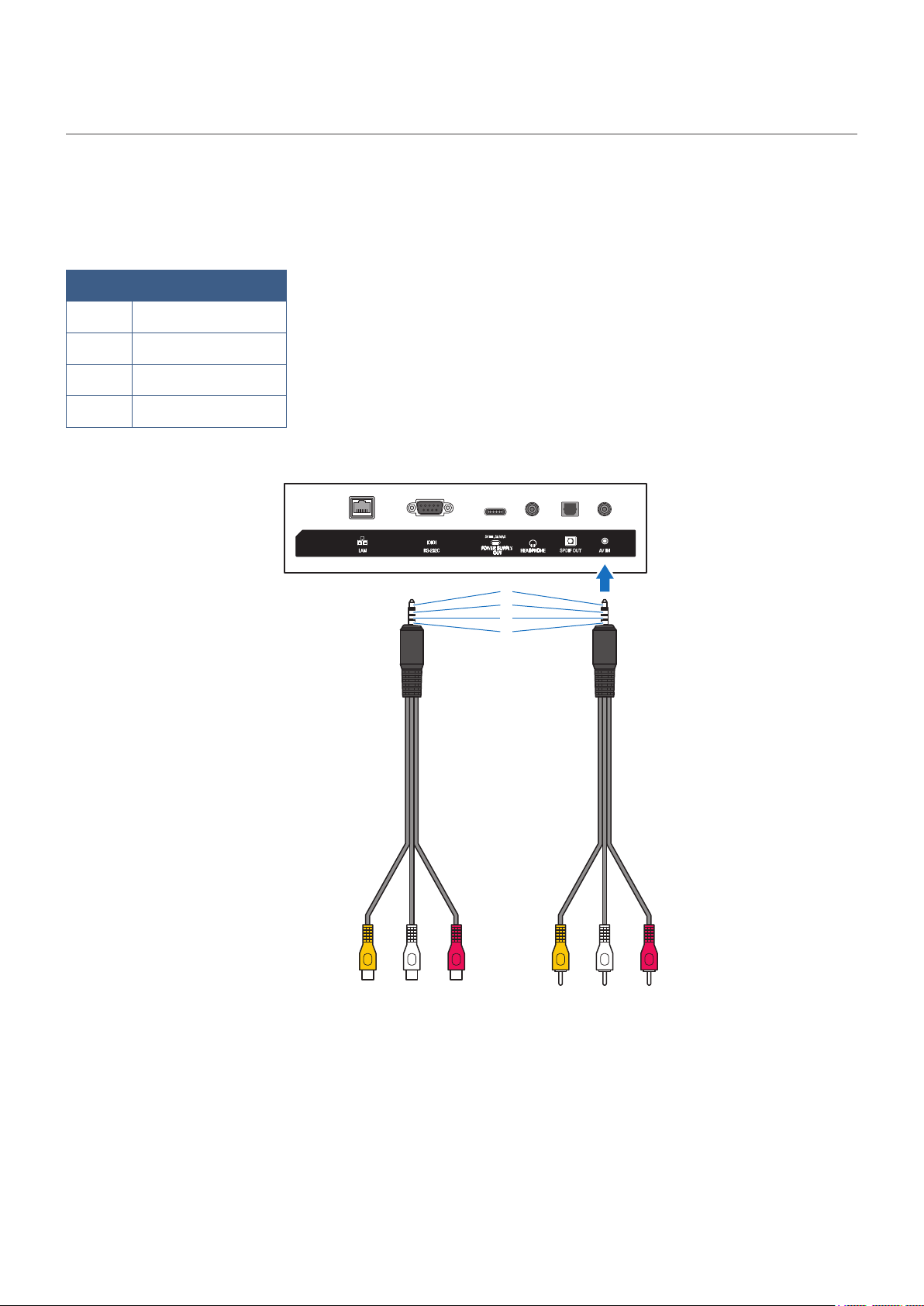
English - 86
Use a commercially-available video cable with a 4-contact mini jack (φ3.5 mm) at one extremity for conversion cables to
connect to the AV terminal.
Check the wiring specication of the cable in advance and choose a proper cable.
*Different wiring specications may exist for 4-contact mini jack cables.
1 Video
2 Audio (left)
3 Audio (right)
4 GND
1
2
3
4
Example of RCA
connectors (male) -
4-contact mini jack cable
Example of RCA
connectors (female) -
4-contact mini jack cable

English - 87
Rev.3