KOMODO-X 6K S35 | V1.0
RED.COM
KOMODO-X™
OPERATION GUIDE

DISCLAIMER IV
SAFETY INSTRUCTIONS VI
1. INTRODUCTION
RED KOMODO-X™ 1
2. QUICK REFERENCE
PREPARING THE CAMERA HARDWARE 4
PREPARING THE CAMERA SYSTEM 4
RECORDING 4
PROCESSING FOOTAGE 4
3. CAMERA COMPONENTS
CAMERA BODY 5
CAMERA BODY CONTROLS AND FEATURES 5
FRONT 5
TOP 6
LEFT 7
RIGHT 8
BACK 9
BOTTOM 10
CAMERA BODY LEDS 11
LENSES AND ADAPTERS 15
COMPATIBLE LENSES 16
COMPATIBLE MOUNT ADAPTERS 16
ATTACHING LENSES 16
REMOVING LENSES 16
ONBOARD LCD TOUCHSCREEN 17
STATUS BAR 21
STATUS PAGE 25
MONITORING TOOLS 26
HISTOGRAM 30
AUDIO TOOLS 31
PLAYBACK 33
4. MENUS
IMAGE / LUT MENU 38
ISO 39
SHUTTER 40
WHITE BALANCE 42
ND 45
OUTPUT COLOR SPACE 46
OUTPUT TONE MAP 46
HIGHLIGHT ROLL-OFF 47
DISPLAY PRESET 48
3D LUT 49
CDL 51
FILM GRADE AND VIDEO GRADE 52
EXPOSURE ADJUST 57
PROJECT SETTINGS MENU 58
FORMAT 59
RECORDING FRAME RATE 63
PROJECT TIME BASE 65
FILE FORMAT 65
R3D QUALITY 68
PRORES RESOLUTION 69
PRORES CODEC 70
PRORES COLOR PROFILE 70
COPYRIGHT © 2023 RED.COM, LLC 955-0218, REV A | ii
TABLE OF CONTENTS
PRE-RECORD 71
RECORDING MODE 73
TIMELAPSE 74
FRAME LIMIT 75
SLATE 76
AUDIO / TC MENU 81
AUDIO SOURCE 83
INTERNAL MICROPHONE 84
EXTERNAL AUDIO 85
HEADPHONE 86
TIMECODE SOURCE 87
TIMECODE DISPLAY MODE 88
MONITORING MENU 89
ONBOARD LCD 90
TOP LCD 93
SDI 96
LIVE STREAM 107
TOOLS 108
GUIDES 116
MEDIA MENU 124
EJECT 124
MEDIA INFO 125
SECURE FORMAT 125
USER SETTINGS MENU 129
PRESETS 129
USER BUTTONS 132
AUTOFOCUS MENU 136
ENABLE 136
MODE 137
SIZE 137
POSITION 137
AF TOGGLE 138
COMMUNICATION MENU 139
CAMERA 139
CONNECTIONS 140
CLIENTS & SERVICES 155
CLOUD UPLOAD 158
SYSTEM SETTINGS MENU 163
DATE / TIME 164
LICENSES 167
LENS 168
POWER 170
SENSOR 171
INDICATORS 172
GPO FUNCTION 174
STATUS SETTINGS 175
SYSTEM STATUS 179
LANGUAGE MENU 181
MAINTENANCE MENU 181
CALIBRATE 182
CALIBRATION 183
SAVE LOG 184
RESET DEFAULTS 185
FACTORY RESET 185
UPGRADE 186
KOMODO-X
®
OPERATION GUIDE

5. HOW TO
WI-FI CONFIGURATION 187
CONNECTING WIRELESSLY TO AN EXISTING
WI-FI NETWORK 187
FTPS CONFIGURATION 190
CAMERA SET-UP 191
SOFTWARE SET-UP (FILEZILLA) 192
ADDITIONAL INFORMATION 193
USB-C CONFIGURATION 194
USB-C APPLE CONFIGURATION 195
USB-C ANDROID CONFIGURATION 202
USB-C ETHERNET CONFIGURATION 208
POWER 211
ATTACHING THE BATTERY 211
REMOVING THE BATTERY 211
POWER COMPONENTS 211
AUTO BOOT ON POWER 211
POWER CONSUMPTION 212
POWER PRIORITY 212
TURNING ON THE CAMERA 212
TURNING OFF THE CAMERA 213
MEDIA MANAGEMENT 213
EJECTING (UNMOUNTING) MEDIA 213
INSERTING THE MEDIA 215
SECURE FORMAT 217
MEDIA INFORMATION 218
FILE SYSTEM 219
CLIP NAMING CONVENTION 219
CLIP METADATA 219
MEDIA BEST PRACTICES 220
RED MONITOR INTERFACE CABLE 221
MONITORING 222
ONBOARD LCD TOUCHSCREEN 222
SDI OUTPUT TO A MONITOR 223
RED CONTROL 225
EXPOSURE 226
FALSE COLOR EXPOSURE TOOLS 228
FOCUS 229
FOCUS PEAKING MODE 229
EDGE PEAKING MODE 229
PEAKING PEAKING MODE 229
TIMECODE 230
TIME OF DAY 230
EDGECODE 231
ZEBRA MODES 233
ZEBRA OVERVIEW 233
PRE-RECORDING CONTENT 234
CALIBRATING THE SENSOR 235
WHEN TO CALIBRATE THE SENSOR 235
UPGRADING THE FIRMWARE 235
VERIFYING THE FIRMWARE VERSION 235
UPGRADING THE FIRMWARE 235
UPGRADING THE DSMC3™ RED® TOUCH
7.0" LCD FIRMWARE 238
UPDATING AUTOMATICALLY THROUGH THE
CAMERA 238
UPDATING MANUALLY THROUGH SMALLHD 238
SYSTEM MAINTENANCE 239
EXTERIOR SURFACES 239
COPYRIGHT © 2023 RED.COM, LLC 955-0218, REV A | iii
STORAGE 239
ONBOARD LCD SCREEN 240
WATER DAMAGE 240
6. TROUBLESHOOTING
GENERAL TROUBLESHOOTING TIPS 241
CONTACT SUPPORT 241
STATUS ICONS 242
A. MECHANICAL DRAWINGS
FRONT VIEW 244
BACK VIEW 245
RIGHT SIDE VIEW 246
LEFT SIDE VIEW 247
TOP VIEW 248
BOTTOM VIEW 249
FEMALE RP SMA PORT 250
USB TYPE-C PORT 251
12G-SDI 252
HEADPHONE JACK 254
AUDIO PORT 255
EXTENSION PORT 256
6-PIN DC-IN 257
B. MENU MAP 258
C. TECHNICAL SPECIFICATIONS 260
D. ACCESSORIES
REDVOLT® NANO-V BATTERY 263
REDVOLT® MICRO-V BATTERY 264
RED® COMPACT DUAL V-LOCK CHARGER 265
CFEXPRESS TYPE B MEDIA 266
RED® CFEXPRESS TYPE B READER 267
KOMODO-X™ RF TO PL ADAPTER PACK 268
KOMODO-X™ RF TO PL WITH ELECTRONIC
ND ADAPTER PACK 269
DSMC3™ RED® TOUCH 7.0" LCD 270
DSMC3™ RED® TOUCH 7.0" LCD HOOD 271
KOMODO-X™ POWER ADAPTOR 272
OUTRIGGER HANDLE 272
KOMODO® WING GRIP 272
RED® COMPACT TOP HANDLE AND
EXTENSIONS 273
DSMC3™ RED® 5-PIN TO SINGLE 3.5 MM
ADAPTER 274
DSMC3™ RED® 5-PIN TO DUAL XLR
ADAPTER 274
RED® PRO I/O MODULE 275
RED CONTROL APPS 276
RED CONTROL 276
RED CONTROL PRO 277
RED CONNECT 277
KOMODO-X
®
OPERATION GUIDE
DISCLAIMER
RED
®
has made every effort to provide clear and accurate information in
this document, which is provided solely for the user’s information. While
thought to be accurate, the information in this document is provided
strictly “as is” and RED will not be held responsible for issues arising
from typographical errors or user’s interpretation of the language used
herein that is different from that intended by RED. All information is
subject to change as a result of changes in local, federal or other
applicable laws.
RED reserves the right to revise this document and make changes from
time to time in the content hereof without obligation to notify any person
of such revisions or changes. In no event shall RED, its employees or
authorized agents be liable to you for any damages or losses, direct or
indirect, arising from the use of any technical or operational information
contained in this document.
This document was generated on 6/27/2023. To see earlier versions of
this document, submit a Support ticket at https://support.red.com.
For comments or questions about content in this document, send a
COPYRIGHT NOTICE
COPYRIGHT© 2023 RED.COM, LLC
All trademarks, trade names, logos, icons, images, written material,
code, and product names used in association with the accompanying
products are the copyrights, trademarks, or other intellectual property
owned and controlled exclusively by RED.COM, LLC. For a
comprehensive list, see www.red.com/trademarks.
TRADEMARK DISCLAIMER
All other company, brand, and product names are trademarks or
registered trademarks of their respective holders. RED has no affiliation
to, is not associated with or sponsored by, and has no express rights in
third-party trademarks. Adobe and Adobe Premiere Pro are registered
trademarks of Adobe Systems Incorporated. DaVinci and DaVinci
Resolve are registered trademarks of Blackmagic Design in the U.S. and
other countries. Leica is a registered trademark of Leica Microsystems.
Canon is a registered trademark of Canon, U.S.A. Apple, iOS,
Macintosh, Final Cut Pro, and QuickTime are registered trademarks of
Apple Inc. in the U.S. and other countries. Windex is a registered
trademark of S. C. Johnson & Son, Inc. Windows is a registered
trademark of Microsoft Corporation. Avid is a registered trademark of
Avid Technology, Inc. FileZilla is a registered trademark of its respective
owners. Nuke™ is a trademark of The Foundry Visionmongers Ltd.
SCRATCH is a registered trademark ® of ASSIMILATE, 2006. SCRATCH
SCAFFOLDS, SCRATCH EXTENSIONS, and SCRATCH Digital
Intermediate Process Solution are all trademarks and registered
trademarks of ASSIMILATE, 2006, All rights reserved. Autodesk, the
Autodesk logo, Flame are registered trademarks or trademarks of
Autodesk, Inc., and/or its subsidiaries and/or affiliates in the USA and/or
other countries.
COMPLIANCE STATEMENTS
INDUSTRIAL CANADA EMISSION COMPLIANCE STATEMENTS
This device complies with Industry Canada license-exempt RSS
standards RSS 139 and RSS 210. Operation is subject to the following
two conditions: (1) this device may not cause interference, and (2) this
device must accept any interference, including interference that may
cause undesired operation of the device.
This Class B digital apparatus complies with Canadian ICES-003.
To comply with FCC and Industry Canada RF exposure limits for general
population/ uncontrolled exposure, the antenna(s) used for this
transmitter must be installed to provide a separation distance of 70 mm
from all persons and operating in conjunction with any other antenna or
COPYRIGHT © 2023 RED.COM, LLC 955-0218, REV A | iv
transmitter, except in accordance with FCC multi-transmitter product
procedures.
Other user manual statements may apply.
Le présent appareil est conforme aux CNR d’Industrie Canada
applicables aux appareils radio exempts de licence. L’exploitation est
autorisée aux deux conditions suivantes : (1) l’appareil ne doit pas
produire de brouillage, et (2) l’utilisateur de l’appareil doit accepter tout
brouillage radioélectrique subi, même si le brouillage est susceptible
d’en compromettre le fonctionnement.
Cet appareil numérique de la classe B est conforme à la norme NMB-
003 du Canada.
Pour se conformer aux limites d’exposition aux RF de la FCC et
d’industries Canda pour la population générale/ exposition non
controlee, l’antenne(s) utilisée pour ce transmetteur doit être installé
pour fournir une distance de separation d’au moins 70 mm de toutes les
personnes et fonctionnant conjointement avec une autre antenne ou
émetteur, saufen conformité avec les proceédures de produits multi-
émetteur FCC.
Autres d’eclarations manuel de l’utilisateur peuvent s’appliquer.
FEDERAL COMMUNICATIONS COMMISSION (FCC) STATEMENTS
This equipment has been tested and found to
comply with the limits for a Class A digital device,
pursuant to part 15 of the FCC Rules. These
limits are designed to provide reasonable
protection against harmful interference when the
equipment is operated in a commercial
environment. This equipment generates, uses, and can radiate radio
frequency energy and, if not installed and used in accordance with the
instruction manual, may cause harmful interference to radio
communications. Operation of this equipment in a residential area is
likely to cause harmful interference in which case the user will be
required to correct the interference at his own expense.
To maintain compliance with FCC regulations, shielded cables must be
used with this equipment. Operation with non-approved equipment or
unshielded cables is likely to result in interference to radio and TV
reception. The user is cautioned that changes and modifications made
to the equipment without the approval of manufacturer could void the
user's authority to operate this equipment.
This device complies with Part 15 of the FCC Rules.
Operation is subject to the following two conditions (1) this device may
not cause harmful interference, and (2) this device must accept any
interference received, including interference that may cause undesired
operation.
CAUTION: Exposure to Radio Frequency Radiation.
The device shall be used in such a manner that the potential for human
contact is minimized.
This equipment complies with FCC radiation exposure limits set forth for
an uncontrolled environment. This equipment should be installed and
operated with a minimum distance of 20 cm between the radiator and
your body.
CAUTION: Regulations of the FCC and FAA prohibit airborne
operation of radio-frequency wireless devices because their
signals could interfere with critical aircraft instruments.
CAUTION: If the device is changed or modified without
permission from RED, the user may void his or her authority
to operate the equipment.
AUSTRALIA AND NEW ZEALAND STATEMENTS
RED declares that the radio equipment described in this document
complies with the following international standards:
KOMODO-X
®
OPERATION GUIDE
IEC 62368-1 – Product Safety
ETSI EN 300 328 – Technical requirement for radio equipment
RED declares digital devices described in this document comply with
the following Australian and New Zealand standards:
AS/NZS CISPR 32 – Electromagnetic Interference
AS/NZS 61000.3.2 – Power Line Harmonics
AS/NZS 61000.3.3 – Power Line Flicker
SOUTH KOREA STATEMENTS
1. Equipment Name/Model Name: Komodo-X / Komodo-X
2. Registration No.: R-R-DV5-2023KX001, R-R-R3d-2022LSR001
3. Applicant Name:㈜ 디브이인사이드
4. Manufacture Date: 2023
5. Manufacturer/Country of Origin: RED Digital Cinema, LLC / USA
JAPAN STATEMENTS
This equipment contains specified radio equipment that has been
certified to the Technical Regulation Conformity Certification under the
Radio Law.
EUROPEAN UNION COMPLIANCE STATEMENTS
RED declares that the radio equipment described
in this document complies with the EMC Directive
(2014/30/EU) and the Low Voltage Directive
(2014/35/EU) issued by the Commission of the
European Community.
Compliance with this directive implies conformity to the following
European Norms (in brackets are the equivalent international standards).
EN 62368-1 (IEC 62368-1) – Product Safety
ETSI EN 300 328 Technical requirement for radio equipment
ETSI EN 301 489 General EMC requirements for radio equipment
EN 55032 (CISPR 32) Electromagnetic Compatibility
EN 55035 (CISPR 35) Immunity Requirements
EN 61000-3-2 (IEC 61000-3-2) Harmonic Current Emissions
EN 61000-3-3 (IEC 61000-3-3) Voltage changes, voltage fluctuations
and flicker
EU 2015/863 RoHS Directive
COPYRIGHT © 2023 RED.COM, LLC 955-0218, REV A | v
WASTE ELECTRICAL AND ELECTRONIC EQUIPMENT (WEEE)
The Waste Electrical and Electronic Equipment
(WEEE) mark applies only to countries within the
European Union (EU) and Norway. This symbol,
on the product and accompanying documents,
means that used electrical and electronic
products should not be mixed with general
household waste. For proper treatment, recovery
and recycling, take this product to designated
collection points where it will be accepted free of
charge. Alternatively, in some countries you may
be able to return your products to your local retailer upon purchase of
an equivalent new product.
Disposing of this product correctly will help save valuable resources and
prevent any potential negative effects on human health and the
environment, which could otherwise arise from inappropriate waste
handling. Contact your local authority for further details of your nearest
designated collection point. Penalties may be applicable for incorrect
disposal of this waste, in accordance with your national legislation.
For business users in the European Union, if you wish to discard
electrical and electronic equipment, contact your dealer or supplier for
further information.
RESPONSIBLE PARTY
RED Digital Cinema
94 Icon
Foothill Ranch, CA 92610
USA
KOMODO-X
®
OPERATION GUIDE
SAFETY INSTRUCTIONS
This equipment is intended to be used by instructed personnel and is
not intended to be used by children.
DO NOT use the camera or accessories near water. Avoid exposing
your camera to moisture. The unit is not waterproof, so contact with
water could cause permanent damage to the unit as well as electric
shock and serious injury to the user. DO NOT use the camera in the
rain or under other conditions with high moisture without appropriate
protection, and immediately remove power source if camera or
accessories are exposed to moisture.
WARNING: To reduce the risk of fire or electric shock, do not
expose the camera to rain or moisture.
DO NOT point the camera directly into extreme light sources such as
the sun or lasers. Permanent damage to optical path or sensor may
occur, which is not covered by manufacturer’s warranty.
DO NOT expose your camera to excessive vibration or impact
(shock). Be careful not to drop your camera. Internal mechanisms
may be damaged by severe shock. Mechanical alignment of optical
elements may be affected by excessive vibration.
ELECTROMAGNETIC INTERFERENCE: The use of devices using
radio or other communication waves may result in the malfunction or
interference with the unit and/or with audio and video signals.
Clean only using a dry cloth. When cleaning your camera, remember
that it is not waterproof and moisture can damage electronic circuitry.
DO NOT rinse or immerse any element of the camera, lens or other
accessory, keep them dry at all times. DO NOT use soaps,
detergents, ammonia, alkaline cleaners, and abrasive cleaning
compounds or solvents. These substances may damage lens
coatings and electronic circuitry.
Maintain sufficient ventilation—DO NOT block any ventilation
openings or obstruct cooling fan airflow.
CAUTION: Proper camera ventilation requires a minimum
0.5" (1.25 cm) clearance between the camera ventilation
openings and external surfaces. Verify that objects that can
block the fan intake and exhaust ports do not impede airflow.
Failure to permit adequate airflow may result in overheating of
the camera, degraded operation, and in extreme situations,
damage to the camera.
WARNING: Media cards can become very hot during
prolonged recording sessions. When ejecting the media card,
let it cool before touching it with bare fingers.
DO NOT operate or store near any heat sources such as radiators,
heat registers, stoves, or any other apparatuses that produce heat.
Store in a protected, level and ventilated place. Avoid exposure to
temperature extremes, damp, severe vibration, strong magnetic fields,
direct sunlight or local heat sources during storage. Remove any
batteries from the camera before storage. Recommended storage
and usage temperatures for your camera, lenses and other
accessories are:
Operating range: 32° F to 104° F (0° C to 40° C)
Storage range: –4° F to 122° F (–20° C to 50° C)
If there are any performance issues with your camera or accessories
when operating within this temperature range, submit a support ticket
to https://support.red.com.
COPYRIGHT © 2023 RED.COM, LLC 955-0218, REV A | vi
DO NOT bypass the third prong of the grounding-type plug on the
power cord of the included power adaptor. A grounding-type plug
has two blades and a third “grounding” prong. The third prong is
provided for your safety. You must connect the plug to an outlet with
a protective earth connection. If the grounding-type plug does not fit
into your outlet, do not attempt to modify the plug or outlet, consult a
qualified electrician.
Protect all power cords from being pinched, walked on, or driven over
by a vehicle. Replace any power cords suspected of sustaining
damage due to crushing or other forms physical damage.
CAUTION: Install this camera in a proper support system that
can handle the entire weight of the camera and the
accessories. Secure the camera by using the ¼-20 and/or the
3/8-16 mounting points located on the bottom of the camera.
Always verify that the screws are tightened properly. When
the camera is not properly attached, or is placed on an
unstable surface, the camera can fall and cause injury or be
damaged.
CAUTION: Products marked with this symbol are Class 2
devices. These double insulated devices are not provided
with a grounding type plug.
CAUTION: The power cord plug for the included power
adaptor is used as the power disconnect. To disconnect all
power from the power adaptor, unplug the power cord plug
from the wall outlet. During use, the power cord plug should
remain easily accessible at all times.
Lithium-ion batteries may be subject to special handling requirements
pursuant to federal and local laws. Refer to specific shipping
instructions included with your battery regarding proper transport of
your battery. Do not handle your battery if it is damaged or leaking.
Disposal of batteries must be in accordance with local environmental
regulations. For example, California law requires that all rechargeable
batteries must be recycled by an authorized recycle center. Storing
batteries fully charged or in high temperature conditions may
permanently reduce the life of the battery. Available battery capacity
may also be temporarily lessened after storage in low temperature
conditions.
WARNING: DO NOT expose the battery to excessive heat.
CAUTION: Refer all service and repair to qualified RED
service personnel. To reduce the risk of electric shock, and
damage to the camera or accessories, DO NOT attempt to
perform any servicing other than any procedures that are
recommended in the operating instructions.
INDOOR USE ONLY: This device is designed primarily for
indoor use.
El aparato no debe quedar expuesto a goteo o salpicadureas por
líquidos.
BATTERY STORAGE AND HANDLING
WARNING: Failure to read, understand, and follow these
instructions may result in overheating, chemical leakage,
smoke emission, fire, or other potentially harmful results.
WARNING: Only replace the battery with a battery of the
same type, or with a battery that is equivalent.
Read and adhere to all safety instructions provided by the
manufacturer of the batteries.
KOMODO-X
®
OPERATION GUIDE
Always follow proper battery handling and storage practices.
Improper handling and failure to abide by proper storage instructions
may cause permanent damage to batteries, or degrade battery
charge holding capacity. Improper handling practices or failure to
comply with instructions may also put you at risk.
Lithium-Ion batteries, like the REDVOLT Micro-V, self-discharge over
time. When storing for long periods of time, store batteries separately
from the camera or charger and remember to charge batteries to a
capacity level of 40% to 60%. If batteries will be stored for long
periods of time, RED recommends that you check the charge level at
least once every six (6) months, and recharge batteries to a capacity
level of 40% to 60%.
When not in use, remove the battery from the camera or charger and
store the battery in a cool, dry place. Avoid extreme hot temperatures
(such as inside a hot car), corrosive gas, and direct sunlight. The
optimal storage temperature for batteries is between
–4° F to 68° F (–20° C to 20° C).
WARNING: Batteries stored in a discharged state for long
periods of time may self-discharge and lose the ability to hold
a charge.
WARNING: If recharging operation fails to complete even
after a specified recharging time has elapsed, immediately
stop further recharging.
DO NOT store batteries in a fully charged state for extended periods
of time.
DO NOT store batteries in a fully discharged state for extended
periods of time.
DO NOT store batteries in the camera or in a charger for extended
periods of time.
DO NOT use batteries for purposes other than their intended use.
DO NOT store batteries in extreme hot or cold temperatures.
DO NOT store batteries in direct sunlight.
DO NOT disassemble or modify the battery.
DO NOT overcharge batteries. Overcharging may increase internal
temperature beyond the recommended limits and cause permanent
damage to the battery.
DO NOT connect the positive (+) and negative (–) terminals to a metal
object such as a wire.
DO NOT transport or store the battery together with metal objects
such as jewelry, hairpins, etc. as they may generate heat if they come
into contact with the battery.
DO NOT discard the battery into fire or heat.
DO NOT store, use, or recharge the battery near a heat source such
as a fire or a heater.
DO NOT allow the battery to get wet.
DO NOT pierce the battery with pointed or other sharp objects.
DO NOT step on, throw, or strike the battery with a hammer.
DO NOT use a battery that appears to be deformed or damaged.
DO NOT directly solder the battery.
DO NOT put the battery into a microwave oven or a pressurized
container.
DO NOT use or subject the battery to intense sunlight or hot
temperatures such as in a car in hot weather.
DO NOT use it in a location where static electricity may be present.
DO NOT exceed the recharging temperature range of 32˚ F to 104˚ F
(0˚ C to 40˚ C).
Store the battery in a location where children cannot reach it.
If the battery leaks or gives off a bad odor, discontinue use
immediately.
If the battery gives off an odor, generates heat, becomes discolored
or deformed, or in any way appears abnormal during use, recharging
or storage, immediately remove it from the equipment or battery
charger and discontinue use.
If electrolyte begins leaking from the battery and comes into contact
with your skin or clothing, immediately wash it away with running
water. Failure to do this may result in skin inflammation.
COPYRIGHT © 2023 RED.COM, LLC 955-0218, REV A | vii
If the battery leaks and the electrolyte reaches the eyes, do not rub
them. Instead, rinse the eyes with clean running water and
immediately seek medical attention. Failure to do this may result in
eye injury.
KOMODO-X
®
OPERATION GUIDE
COPYRIGHT © 2023 RED.COM, LLC 955-0218, REV A | 1
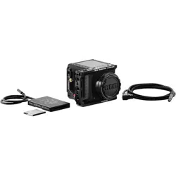
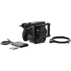
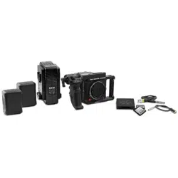
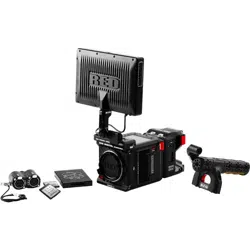
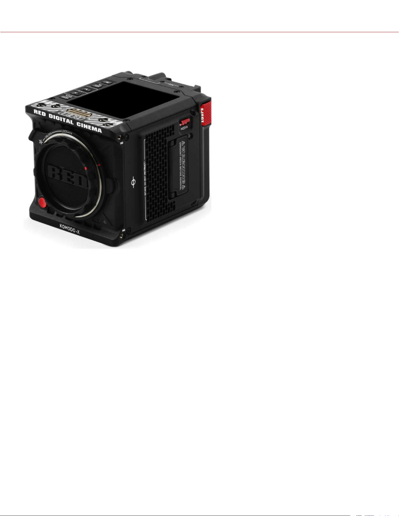
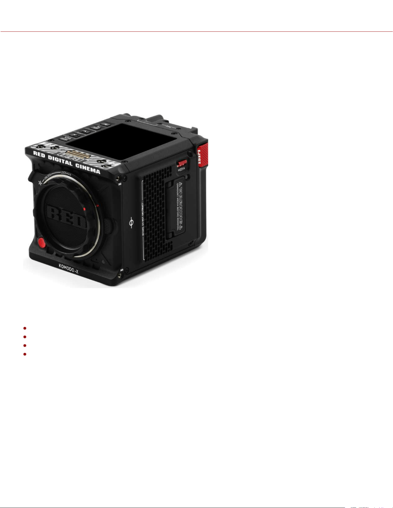
1. INTRODUCTION
Figure: RED KOMODO-X™ camera
RED KOMODO-X™
KOMODO-X is the next evolution in the KOMODO family, multiplying the frame rates, dynamic range, and usability of
the original KOMODO to break new grounds.
NEXT GENERATION KOMODO SENSOR
KOMODO-X features the same sized 6K S35 Global Shutter sensor as the KOMODO, but with a ground up redesign
and key architecture improvements.
Improved detail and color in shadows, paired with double the frame rates at 6K 80P and 4K 120P makes KOMODO-X
an even more powerful tool for creatives.
ENHANCED BODY AND I/O
With key improvements for professional workflows, the KOMODO-X now shares many features with the DSMC3 line
while still maintaining the impressively small KOMODO form factor. An integrated micro V-Lock allows for direct
attachment of professional micro V-Lock batteries without the need for adapters and is also compatible with the
upcoming RED PRO I/O Module to provide auxiliary power and compatibility with full sized V-Lock and Gold Mount
batteries.
A reinforced RF lens mount with locking mechanism maintains the flexibility of toolless switching between multiple lens
mount types, while providing the stability and rigidity professionals need. KOMODO-X is also fully compatible with /i PL
lenses using the RED RF to PL Adapter.
12G SDI, full sized DC-IN, USB Type-C, and a phantom powered locking audio connector further enables KOMODO-X
to seamlessly integrate into any professional workflow. KOMODO-X is compatible with DSMC3™ RED® 5-Pin to Single
3.5 mm Adapter to support existing KOMODO microphones, or the DSMC3™ RED® 5-Pin to Dual XLR Adapter for
general purpose XLR microphones.
KOMODO-X
®
OPERATION GUIDE

An integrated 2.9” LCD allows for simplified control and image preview in compact setups. For more precise monitoring,
KOMODO-X supports the DSMC3 7” Touch LCD which provides a daylight viewable, high-resolution, camera top
monitor and control solution without the mess of cables.
IP CONNECTED
KOMODO-X is a powerful platform for any IP based workflow, from Virtual Production to Live Broadcast. With
integrated USB Type-C connection and built-in Wi-Fi, remotely control the camera using RED Control or RED Control
Pro, as well as IP media offloading using FTPS or in-camera Cloud Uploading functionality. In addition, KOMODO-X
supports frame-accurate PTP synchronization or tri-level genlock sensor sync with the ability to offset on the fly to
support multi-camera LED volume productions.
KOMODO-X also supports RED Connect, a licensed feature that allows for live broadcasting of 6K images directly from
the camera over IP, expanding RED’s cinematic imagery into boundless new uses.
QUICK REFERENCE
Refer to the Quick Reference section to get familiar with this guide and the camera.
R3D FILE FORMAT AND REDCODE
All videos and frames are recorded to the R3D
®
file format. The R3D file format was developed by RED to provide an
efficient and manageable RAW video data format that promotes advanced post-production editing capabilities. In the
R3D file format, the digital image received from the sensor is formatted as a pixel-defect corrected (but in all other
aspects unprocessed) 16-bit per pixel RAW data frame. Each RAW frame, or sequence of RAW frames in a clip, is
compressed using proprietary REDCODE
®
RAW compression, then stored to media.
RAW data is recorded independently of any RGB domain color processing such as ISO, White Balance, or other RGB
color space settings. Instead, color parameters are saved as reference metadata; that is, color is not burned into the
recorded RAW data. This innovative recording technique promotes flexibility in RGB color processing. It allows you to
defer color correction to post-production, or to adjust the image color in the field, without changing the recorded RAW
data image quality or dynamic range.
REDCODE is a compression codec that reduces R3D RAW files down to a manageable size, allowing the media to
record longer. The ability to compress RAW data is one of the significant technological advances that RED has brought
to the motion picture industry.
GLOBAL SHUTTER
This camera employs global shutter technology. This technology exposes all of the sensor's pixels in each frame
simultaneously, unlike a rolling shutter that exposes lines of pixels (each with a delay) causing image artifacts on fast-
moving objects. Global shutter technology not only improves the visual appearance of this camera's images, it also
eliminates tracking and matte-painting distortions during post production.
IMAGE PROCESSING PIPELINE
This camera uses RED's Image Processing Pipeline 2 (IPP2). In IPP2, the advanced RED color space
(REDWideGamutRGB) allows the camera to use every color that the sensor can generate up to the clipping threshold.
Then the camera encodes the image using Log3G10, a gamma curve that retains extreme highlight and shadow detail.
Using the advanced color space and gamma curve, RED IPP2 allows you to grade and make color adjustments in post-
production, instead of in-camera. IPP2 also allows the camera to use a CDL for grading. For more information about
IPP2, refer to the RED IPP2 support page.
SHOOT FOR VIDEO AND STILLS
High resolution video, such as the digital footage captured by the camera, has surpassed the detail necessary to
produce professional full-sized prints. Because the camera is able to record RAW video at high frame rates and
resolution, this camera is ideally suited to capture video and still images simultaneously while still preserving the full
flexibility that RAW still photographers have come to expect.
COPYRIGHT © 2023 RED.COM, LLC 955-0218, REV A | 2
KOMODO-X
®
OPERATION GUIDE
POST-PRODUCTION
Many non-linear editing systems (NLEs) can open and edit RED footage, allowing full RAW control and flexibility without
any need to re-transcode. Each NLE version may have specific compatibility requirements, such as camera firmware
version or camera type. Before shooting, make sure you check all of the compatibility requirements.
You can open and/or edit R3D files by using one of the following products:
REDCINE-X PRO: RED's proprietary application. Download REDCINE-X PRO for Windows or REDCINE-X PRO for
Mac from www.red.com/downloads.
Adobe Premiere Pro
Avid Media Composer
DaVinci Resolve
Final Cut Pro X: Requires you to download the RED Apple Workflow Installer from www.red.com/downloads.
Foundry Nuke
Assimilate Scratch
AutoDesk Flame
ColorFront Transkoder (beta for latest support)
Pomfort Silverstack
NOTE: Third-party applications may have limited compatibility with R3D files. Third-party developers must use the most
recent R3D SDK to offer compatibility with the latest RED firmware.
POST-PRODUCTION WITH REDCINE-X PRO
REDCINE-X PRO is a professional one-light coloring tool set, equipped with an integrated time line, and with a
collection of post effects software. REDCINE-X PRO provides the ideal environment to review recorded footage, edit
metadata, organize projects, and prepare your R3D files. You can use REDCINE-X PRO or any of the compatible third-
party NLEs to edit R3D files.
ADDITIONAL RESOURCES
RED.com: Visit the official RED website for the latest information about RED products.
RED Downloads: Go to RED Downloads to download the latest firmware, operation guides, and post-production
software.
RED 101 Articles: RED offers in-depth technical articles about RED cameras, post-production, and digital
cinematography.
RED TECH Videos: RED offers videos about understanding and using RED cameras.
RED Support: Visit the RED SUPPORT site for support articles or to file a support ticket.
COPYRIGHT © 2023 RED.COM, LLC 955-0218, REV A | 3
KOMODO-X
®
OPERATION GUIDE
COPYRIGHT © 2023 RED.COM, LLC 955-0218, REV A | 4
2. QUICK REFERENCE
Congratulations new RED KOMODO-X™ 6K S35 camera owner. This quick reference topic helps you get familiar with
this guide and the Camera Body. It includes links to topics about configuring the camera to fit your recording
requirements, and for learning the basic operation of the camera.
PREPARING THE CAMERA HARDWARE
Prepare the camera hardware for recording by:
Attaching accessories (refer to Accessories)
Installing Lenses and Adapters
Inserting the Media
Connecting a power source (refer to Power or Accessories)
Turning On the Camera
PREPARING THE CAMERA SYSTEM
Configure the camera settings to prepare for recording by:
Configuring the camera system settings (refer to the System Settings Menu)
Upgrading the Firmware and Upgrading the DSMC3™ RED® Touch 7.0" LCD Firmware
Calibrating the camera using the Calibrate feature
Formatting the media (refer to Secure Format)
Specifying the desired recording resolution (refer to Format)
Configuring the Recording Frame Rate and Project Time Base
Setting the exposure (refer to Shutter)
Configuring the monitoring tools and reviewing the monitored image (refer to the Monitoring Menu)
Reviewing the camera status (refer to System Status)
RECORDING
Start recording your project.
Record by pressing the REC button on the Camera Body, Outrigger Handle, or RED® Compact Top Handle and
Extensions
Record by using the Top LCD (refer to DSMC3™ RED® Touch 7.0" LCD)
Record by using an external trigger (refer to Extension Port)
Start, stop, and control the camera by using USB-C (refer to USB-C Configuration)
Start, stop, and control the camera by using Wi-Fi (refer to How To)
PROCESSING FOOTAGE
Perform post-production using any of the standard applications.
Adobe
®
Premiere
®
Pro
Avid
®
Media Composer
®
DaVinci Resolve
®
Final Cut Pro X
®
NOTE: Third-party applications may have limited compatibility with R3D files. Third-party developers must use the most
recent R3D SDK (8.3 or later) to offer compatibility with the latest RED firmware.
KOMODO-X
®
OPERATION GUIDE
COPYRIGHT © 2023 RED.COM, LLC 955-0218, REV A | 5
3. CAMERA COMPONENTS
CAMERA BODY
This section describes the Front, Top, Left, Right, Back, and Bottom of the camera, and identifies the controls, buttons,
Camera Body LEDs, and the lens mount on the body.
CAMERA BODY CONTROLS AND FEATURES
This section describes the controls and features of the camera.
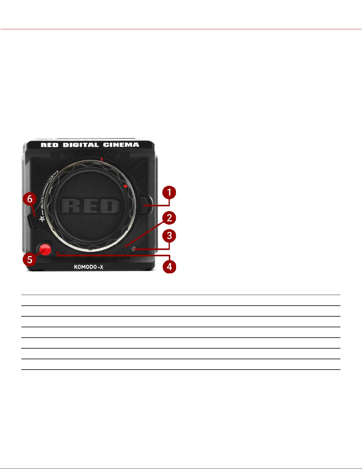
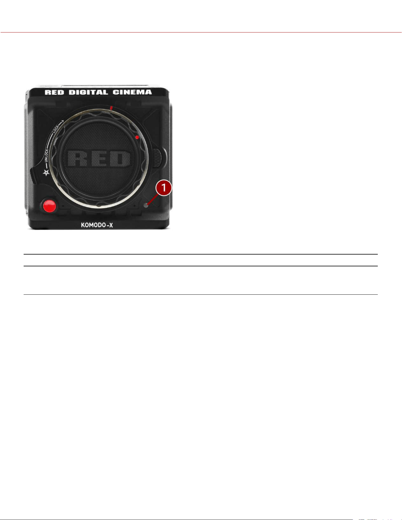
FRONT
Figure: Camera Body Front Controls and Features
#
ITEM DESCRIPTION
1
Lens release Press to release RF-type lenses
2
Mic 1 Left Internal Microphone channel
3
Tally light Tally light (refer to Camera Body LEDs and Indicators)
4
Mic 2 Right Internal Microphone channel
5
Front REC button Press and release the REC button to toggle between record start and stop
6
Lens locking ring Rotate to lock and unlock lenses
KOMODO-X
®
OPERATION GUIDE
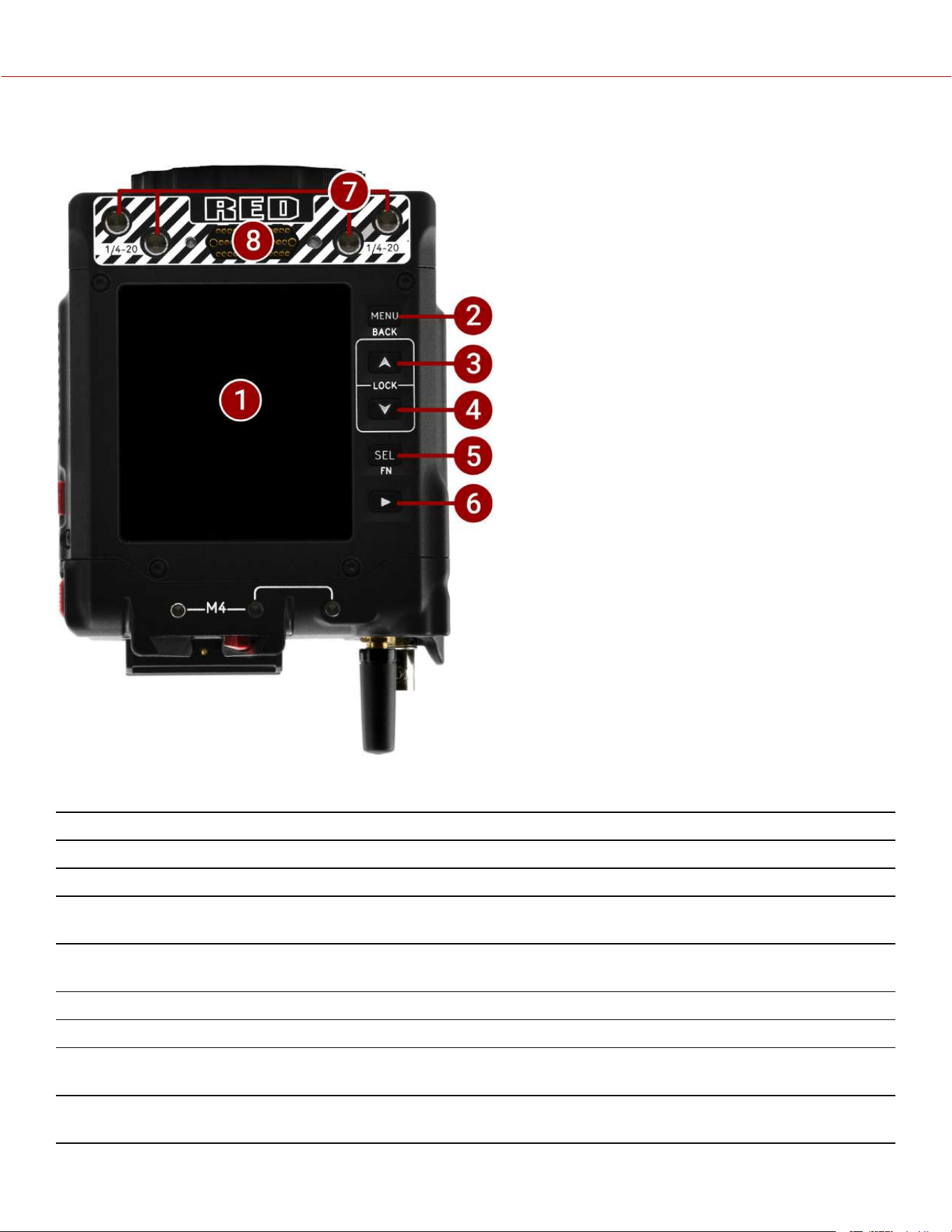
TOP
Figure: Camera Body Top Controls and Features
#
ITEM DESCRIPTION
1
LCD Touchscreen Camera Onboard LCD Touchscreen
2
MENU (BACK) Button Menu button, Back button
3
Up Arrow (LOCK)
Button
Navigates up in the menu and locks/unlocks the UI when pressed along with the other
Lock button
4
Down Arrow (LOCK)
Button
Navigates down in the menu and locks/unlocks the UI when pressed along with the other
Lock button
5
Select Button Selects the highlighted menu item
6
Playback Button Opens the Playback screen
7
1/4-20 Mounting
Holes
1/4-20 mounting holes for optional accessories (refer to Outrigger Handle, DSMC3™
RED® Touch 7.0" LCD)
8
Accessory Port Connection port for accessories (refer to Outrigger Handle, DSMC3™ RED® Touch 7.0"
LCD)
COPYRIGHT © 2023 RED.COM, LLC 955-0218, REV A | 6
KOMODO-X
®
OPERATION GUIDE
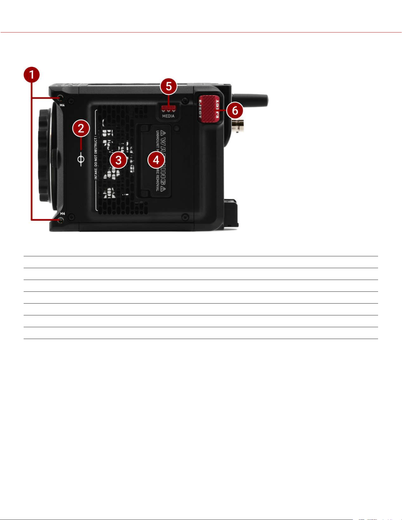
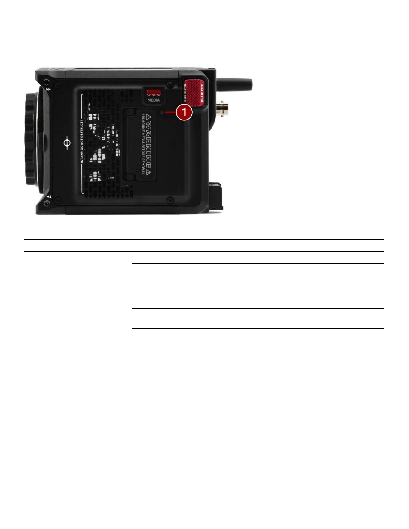
LEFT
Figure: Camera Body Left Controls and Features
#
ITEM DESCRIPTION
1
M4 Mounting Holes Two (2) M4 mounting points for accessories
2
Focus Plane Focus plane indicator symbol
3
Air intake Air intake for thermal management
4
Media compartment CFexpress Type B compartment
5
Access media Latch for the CFexpress Type B media compartment door
6
EJECT Button Micro-V battery eject button
COPYRIGHT © 2023 RED.COM, LLC 955-0218, REV A | 7
KOMODO-X
®
OPERATION GUIDE
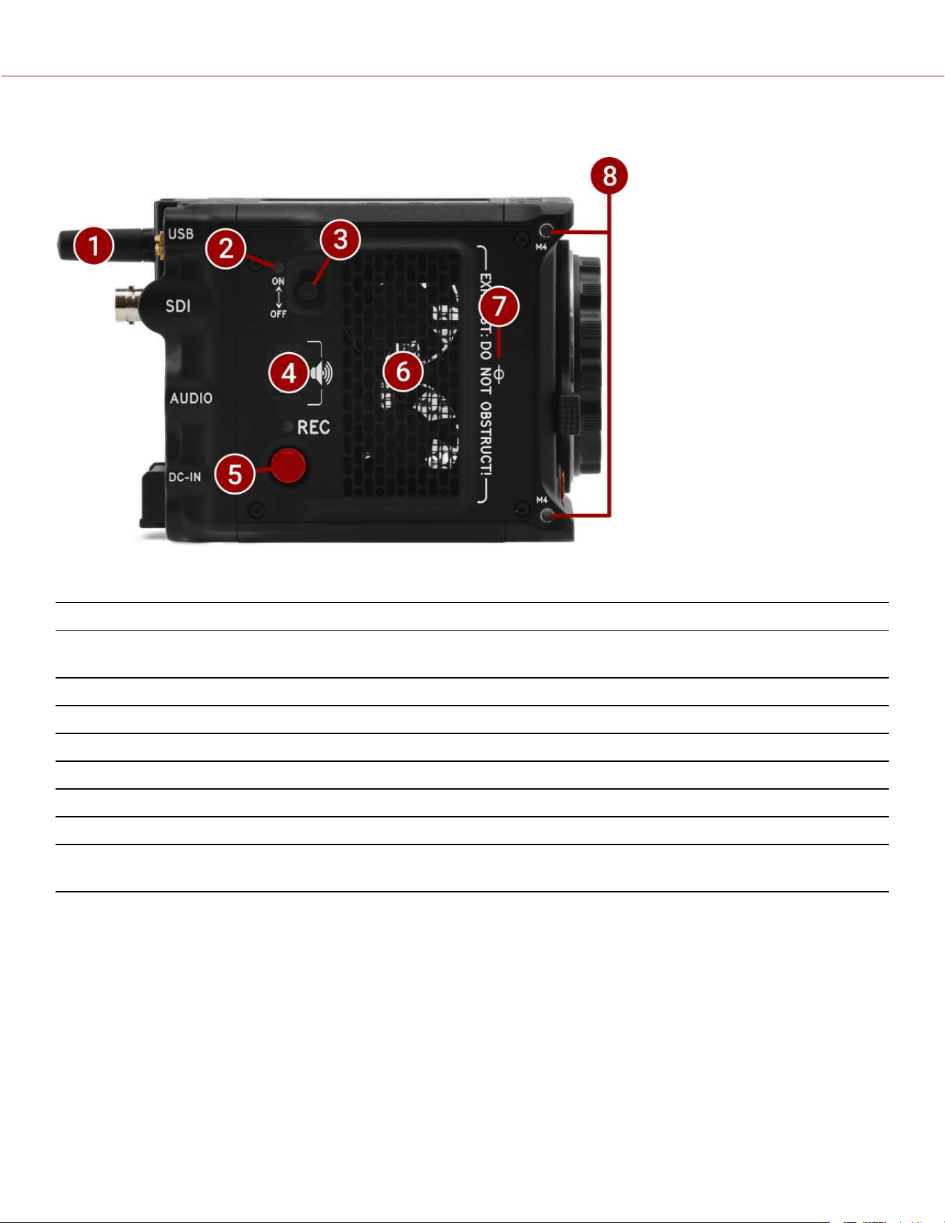
RIGHT
Figure: Camera Body Right Controls and Features
#
ITEM DESCRIPTION
1
Wireless antenna Wi-Fi antenna mounted to a female RP-SMA connector. Supports dual band 2.4 GHz or 5
GHz
2
Power LED Displays the camera ready status (refer to Camera Body LEDs)
3
ON/OFF switch Slide up to turn on the camera and slide down to turn off the camera
4
Speaker Beep speaker for audible feedback
5
Right REC button Assignable full-press and half-press button
6
Exhaust Exhaust for thermal control
7
Focus plane Focus plane indicator symbol
8
M4 mounting
holes
Two (2) M4 mounting points for accessories
COPYRIGHT © 2023 RED.COM, LLC 955-0218, REV A | 8
KOMODO-X
®
OPERATION GUIDE
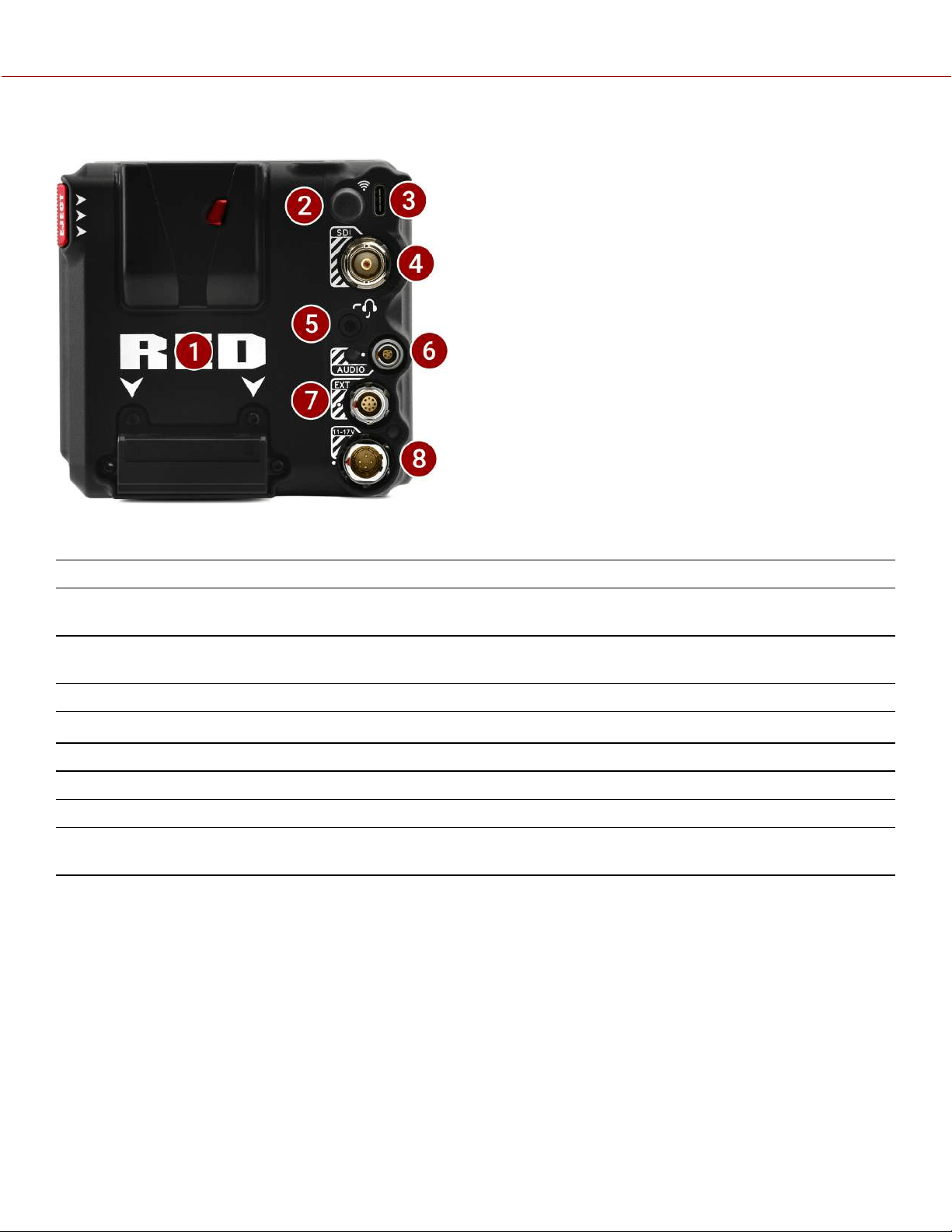
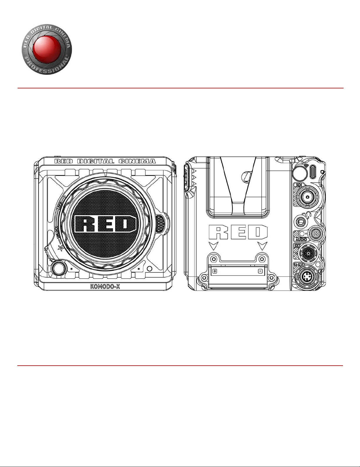
BACK
Figure: Camera Body Rear Controls and Features
#
ITEM DESCRIPTION
1
Micro V-Lock battery
mount
14.4 V Micro V-Lock mount(refer to REDVOLT® MICRO-V Battery and REDVOLT®
NANO-V Battery)
2
Wireless antenna Wi-Fi antenna mounted to a female RP-SMA connector. Supports dual band 2.4 GHz or
5 GHz
3
USB Type-C port USB Type-C Port for USB-C connection
4
12G-SDI port Full-size 12G-SDI BNC port for SDI monitor connection
1,2
5
Headphone port 3.5 mm stereo headphone output
6
Audio port and LED 5-Pin 00B ODU for 2 channel audio (Line, Mic, and +48V)
7
9-pin Extension Port 9-pin 0B ODU port (refer to Extension Port)
8
6-pin DC-IN port and
LED
6-pin 1B ODU for DC-IN (11-17 Volts) and power status LED (refer to 6-pin DC-IN)
1. Use certified 12G-SDI cables.
2. WARNING: Always connect the accessories' DC power cable (or batteries) before connecting the BNC SDI cable. Always remove the BNC SDI
cable before removing the accessories' DC power cable (or batteries). For more information, refer to Preventing Damage to SDI Outputs.
COPYRIGHT © 2023 RED.COM, LLC 955-0218, REV A | 9
KOMODO-X
®
OPERATION GUIDE
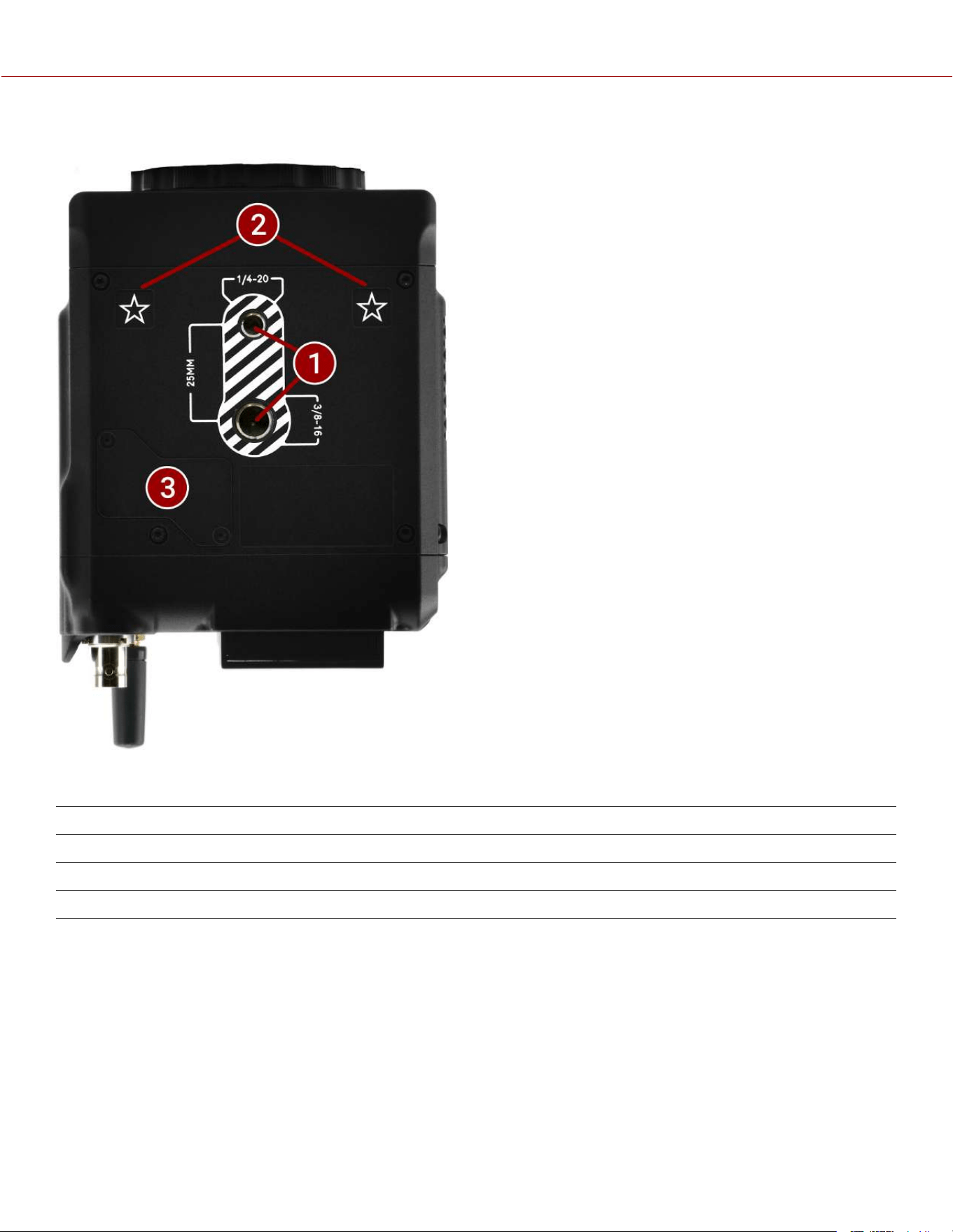
BOTTOM
Figure: Camera Body Bottom Controls and Features
# ITEM DESCRIPTION
1 Mounting Points One (1) 1/4"-20 mounting hole and one (1) 3/8"-16 mounting hole
2 Registration Points Indented alignment points
3 Service Port For RED service only - DO NOT REMOVE
COPYRIGHT © 2023 RED.COM, LLC 955-0218, REV A | 10
KOMODO-X
®
OPERATION GUIDE
LEFT SIDE LED
Figure: Camera LED, Left Side
#
ITEM COLOR/FLASHING DESCRIPTION
1
CFexpress Media LED Off No media mounted
Green Preview; media mounted with > 10% of
media space available
Amber Recording finalizing or playback mode
Amber flashing slow Formatting media
Red flashing slow Media mounted with >5% and <= 10% of
media space available
Red flashing fast Media mounted with <= 5% of media space
available
Red Recording
COPYRIGHT © 2023 RED.COM, LLC 955-0218, REV A | 12
KOMODO-X
®
OPERATION GUIDE
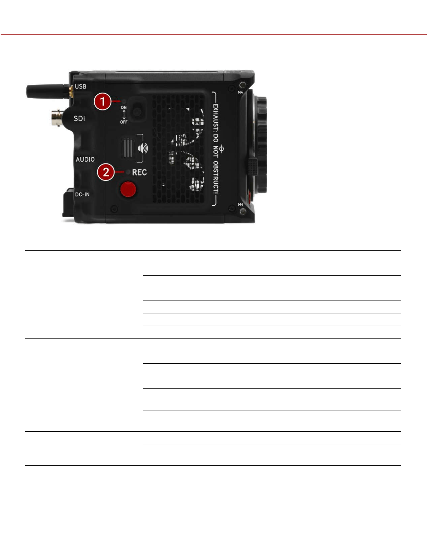
RIGHT SIDE LEDS
Figure: Camera LED, Right Side
#
ITEM COLOR/FLASHING DESCRIPTION
1
Power Status (ON) Off Camera OFF
Amber Camera booting
Green Camera ON
Amber flashing Camera on; 5 to 10 min of battery time available
Red flashing Camera on; < 5 min of battery time available
Red Camera shutting down
2
Record Status (REC) Off No media present
Green Ready to record
Red Recording
Amber Finalizing
Red flashing slow Media mounted with >5% and <= 10% of media
space available
Red flashing fast Media mounted with <= 5% of media space
available
3
Power (firmware update) Flashing green Firmware update in progress
Flashing red Firmware update error (refer to Upgrading the
Firmware)
COPYRIGHT © 2023 RED.COM, LLC 955-0218, REV A | 13
KOMODO-X
®
OPERATION GUIDE

BACK LEDS
Figure: Camera LEDs, Rear
#
ITEM COLOR DESCRIPTION
1
Phantom
power
Blue Indicates that the +48 V Phantom Power is enabled
2
DC-IN Green DC-IN is present and / or the battery is fully charged
Flashing Amber Communicating with, and evaluating the battery
Amber Charging connected batteries
Red Error charging the batteries
COPYRIGHT © 2023 RED.COM, LLC 955-0218, REV A | 14
KOMODO-X
®
OPERATION GUIDE
LENSES AND ADAPTERS
This section lists the compatible lenses and adapters for the camera. It also provides the steps for Attaching Lenses
and Removing Lenses.
For more information on a specific lens or adapter, refer to the original manufacturer’s instructions.
WARNING: When the camera is not in use, protect lenses and the camera sensor by attaching the lens caps and
camera mount cap.
Figure: Camera with mount cap installed.
Incompatible lenses may not register on the camera UI or show any UI lens information or menu controls. The camera
can control compatible lenses electronically, including the following features:
Iris - The UI menu is enabled and the camera can control the lens Iris
Autofocus - The UI menu is enabled for lenses that support autofocus
Image Stabilization - The UI indicates that image stabilization is present
Control Ring - The UI menu is enabled and the camera can use the control ring
For more information, refer to the Lens menu.
COPYRIGHT © 2023 RED.COM, LLC 955-0218, REV A | 15
KOMODO-X
®
OPERATION GUIDE
COMPATIBLE LENSES
The latest RED-tested and approved lenses are listed on the KOMODO-X section of RED Support.
LENS WEIGHT AND LENS SUPPORT
Use a lens support system when mounting heavy or long lenses to your camera.
When mounting a heavy or long lens, ensure that the full weight of the lens is never directly on the camera or lens
mount. Mount the lens to the support system first, and then carefully mount the lens to the camera.
COMPATIBLE MOUNT ADAPTERS
RED tested the following adapters and determined that they are compatible with the camera:
KOMODO-X™ RF to PL Adapter (refer to KOMODO-X™ RF to PL Adapter Pack)
Canon Mount Adapter EF-EOS R
Canon Drop-In Filter Mount Adapter EF-EOS R with Variable ND Filter / Clear Filter / Circular Polarizer
ATTACHING LENSES
1. Unlock the locking ring by rotating it to the fully counterclockwise position.
2. Press and hold the lens release button on the camera. While holding the lens release button, turn the camera lens
mount cap counter-clockwise until it stops, and remove it from the camera. If the lens locking ring rotates while
removing the cap, make sure that you hold the locking ring tab in place while rotating the cap.
3. Remove the rear lens cap from the mount end of the lens.
4. Align the red dot on the lens mount with the red dot on the camera lens mount, and insert the lens mount of the lens
in the camera lens mount opening.
5. Turn the lens clockwise until it clicks in place. If the lens locking ring rotates while attaching the lens, make sure that
you hold the locking ring tab in place while rotating the lens or adapter.
6. Gently tighten the locking ring. DO NOT OVER-TIGHTEN THE LOCKING RING.
7. Store the camera lens mount cap and the rear lens cap together in a dust free location.
REMOVING LENSES
1. Loosen the locking ring gently.
2. Press and hold the lens release button on the camera. While holding the lens release button, turn the lens counter-
clockwise until it stops, and remove it from the camera. If the lens locking ring rotates while removing the lens, make
sure that you hold the locking ring tab in place while rotating the lens or adapter.
3. Align the red dot on the camera lens mount cap with the red dot on the camera lens mount, and attach the cap to the
camera.
4. Gently tighten the locking ring. DO NOT OVER-TIGHTEN THE LOCKING RING.
5. Attach the rear lens cap to the lens.
6. Store the lens with the front and rear caps attached.
COPYRIGHT © 2023 RED.COM, LLC 955-0218, REV A | 16
KOMODO-X
®
OPERATION GUIDE
ONBOARD LCD TOUCHSCREEN
This section describes the structure and layout of the graphical user interface
(GUI) for the Onboard LCD touchscreen. Advanced GUI menu controls
enable convenient access to menus, camera features, and critical camera
information.
NOTE: After 1 hour of inactivity, the touchscreen will go to sleep. Tap the
touchscreen or touch any button to wake the touchscreen. The touchscreen
will not sleep while the camera is recording.
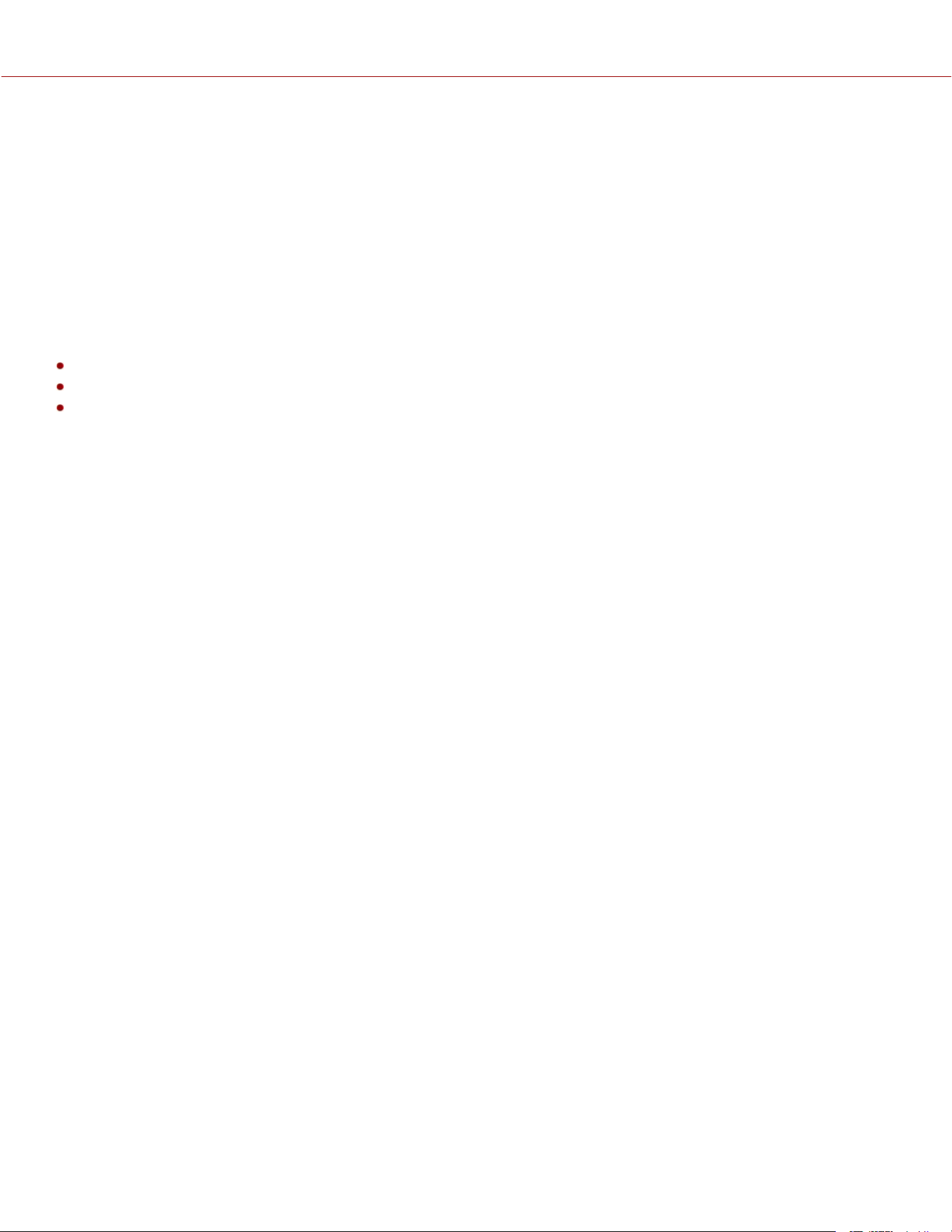
The Onboard LCD Touchscreen home page contains the following features:
STATUS BAR
The Status Bar contains the button for displaying the Home screen and Menu screen. It also contains status icons for
various camera settings and inputs.
When you tap the Home/Menu toggle button (RED logo), the camera toggles the display between the menu page and
the home page:
COPYRIGHT © 2023 RED.COM, LLC 955-0218, REV A | 17
KOMODO-X
®
OPERATION GUIDE
When you tap the Status bar icons the Status Page displays:
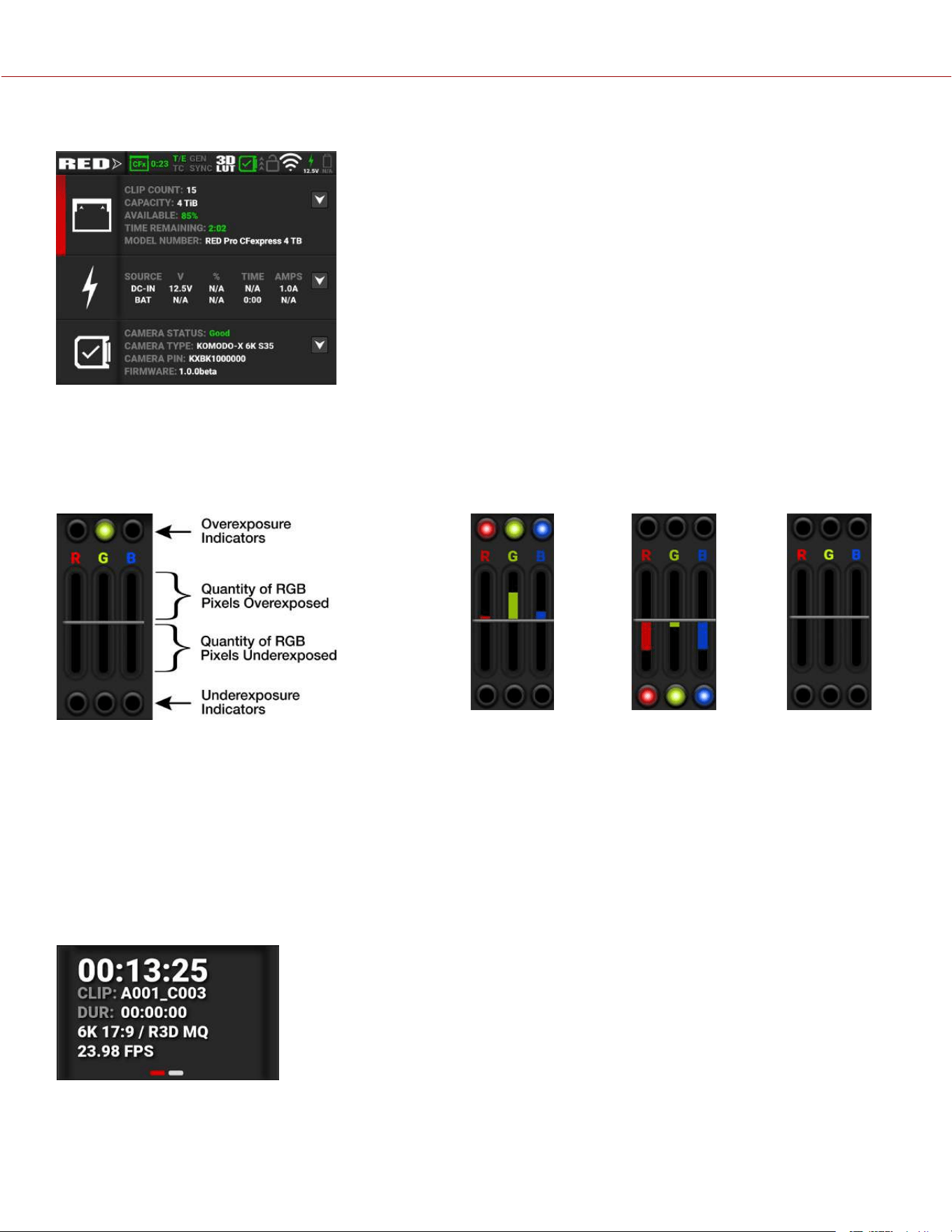
EXPOSURE
The Exposure section of the Onboard LCD home page displays the RGB exposure levels for the camera.
Exposure
Meter
Overexposed
Example
Underexposed
Example
Balanced
Example
RGB Exposure displays the pixel exposure quantity of the separate RGB channels and indicates when a channel is
underexposed or overexposed. This meter measures the raw image data regardless of the ISO and LUT settings.
The top and bottom RGB lights illuminate when a small number of pixels on the sensor are overexposed or
underexposed. This indicates that a small bright or dark area is in the image.
The level bars show the levels of overexposed and underexposed RGB pixels on the sensor. Adjust the settings on the
camera to compensate.
Tap the Exposure section to toggle between this display and the Monitoring Tools page display.
MEDIA / HISTOGRAM
The Media section of the
Onboard
LCD home page displays the Timecode or
Edgecode, clip ID, clip duration, resolution/format, and frame rate for the camera.
Tap the Media section to toggle between this display and the Histogram display.
COPYRIGHT © 2023 RED.COM, LLC 955-0218, REV A | 18
KOMODO-X
®
OPERATION GUIDE
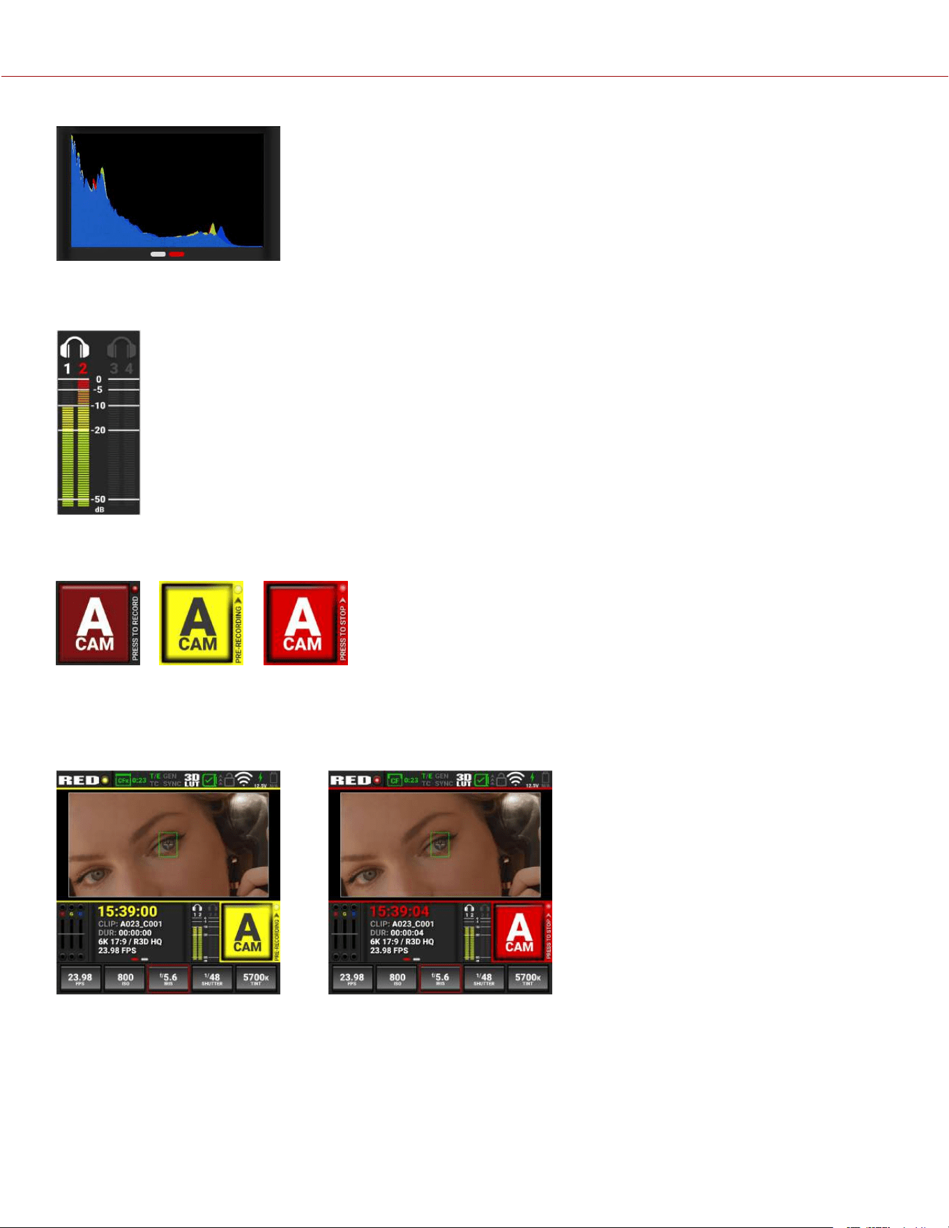
The Histogram section of the Onboard LCD home page displays the image color
histogram. Tap this area to toggle between this display and the Media display. For
more information, refer to Histogram.
AUDIO
The Audio section of the Onboard LCD home page displays the audio levels for the camera. Tap the
Audio section to toggle between this display and the Audio Tools display.
The Audio VU meters display the audio levels in decibel (dB) for the selected channels. Refer to the
Audio / TC Menu section for more information about the audio channels.
In this example, channel 2 displays the VU meter clipping at maximum dB.
CAMERA DESIGNATION AND REC BUTTON
The Camera Designation and Record button on the Onboard LCD touchscreen home page displays the camera letter
assigned to the camera (refer to Slate and Camera ID). You can tap this area to start pre-recording, and to start and
stop recording.
Pre-recording: Recording:
COPYRIGHT © 2023 RED.COM, LLC 955-0218, REV A | 19
KOMODO-X
®
OPERATION GUIDE
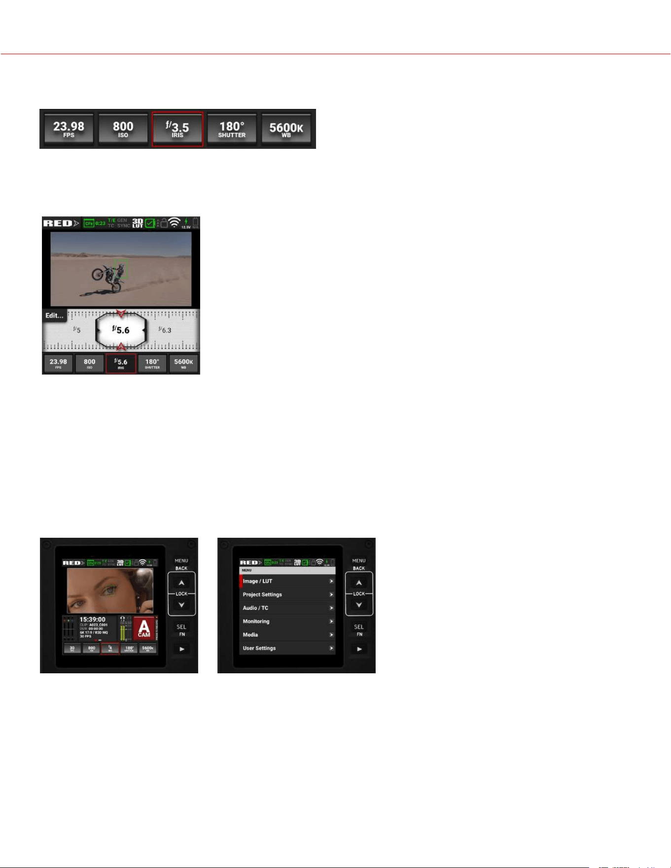
QUICK SETTINGS
The Quick Settings section of the Onboard LCD home page displays the Quick Settings buttons for changing the most
often used camera settings. These settings include Recording Frame Rate, ISO, IRIS (refer to Lens), Shutter, and White
Balance.
Tap on a Quick Setting button to change the settings.
Swipe the setting left or right to make a selection.
Tap Edit to manually enter a value.
Tap List to manage which values display in this tool.
Tap on the Quick Setting button to close the selection screen.
Tap and hold the Shutter button to quickly toggle between Time and Angle settings.
Tap and hold the White Balance (WB) button to quickly switch between Kelvin and
Presets.
BUTTON NAVIGATION
Pressing the Menu button next to the Onboard LCD touchscreen opens the main menu page. You can select the
desired menu items by using the Up, Down, and Select (SEL) buttons. Pressing the Menu button also navigates
backwards (BACK) from submenus in the menu tree.
Pressing the Up arrow and the Down arrow simultaneously locks/unlocks the touchscreen and the menu buttons. The
Lock icon in the Status bar displays the lock status. The REC button is not locked and it functions normally.
Pressing the Playback button starts and stops playback (refer to Playback for more information).
Home Screen Menu Screen
COPYRIGHT © 2023 RED.COM, LLC 955-0218, REV A | 20
KOMODO-X
®
OPERATION GUIDE
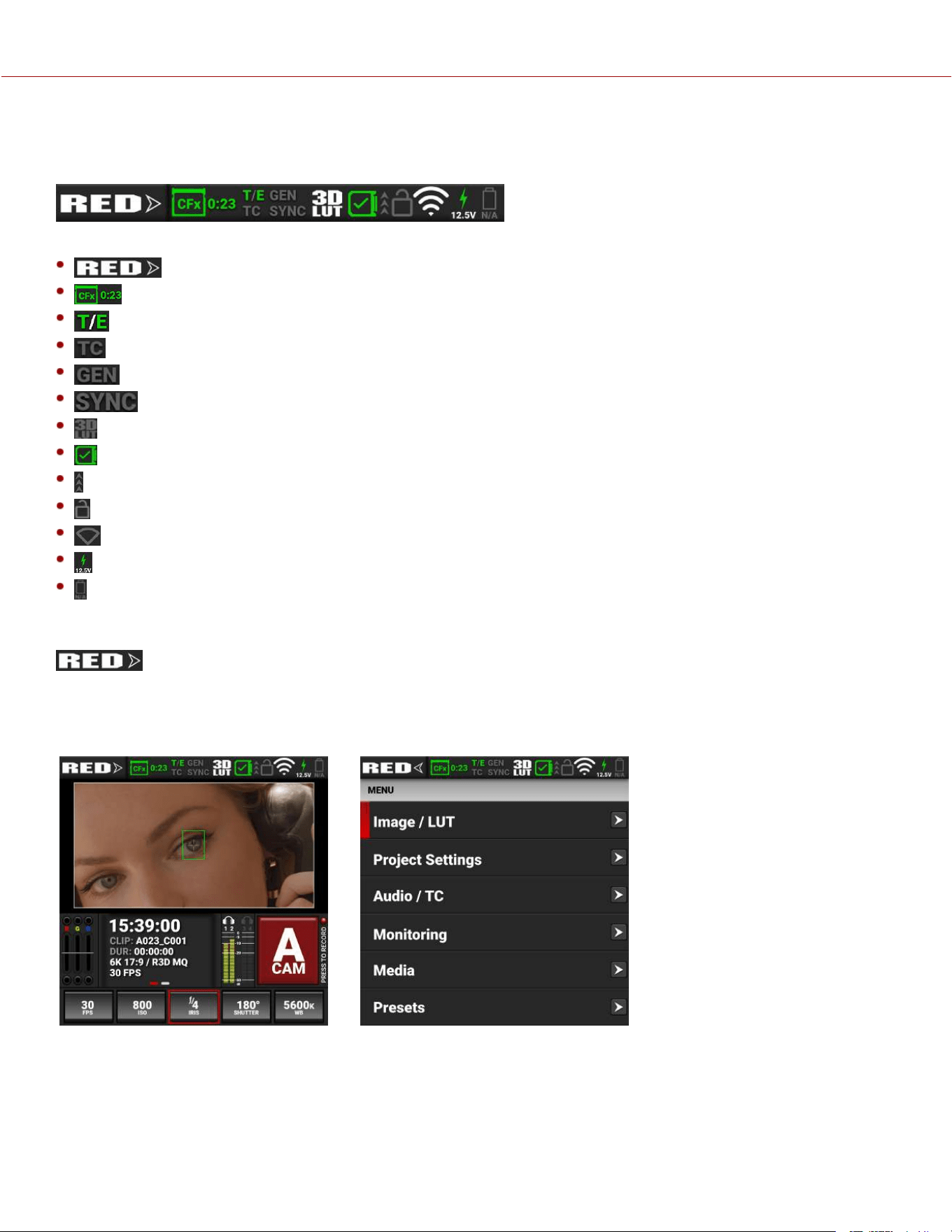
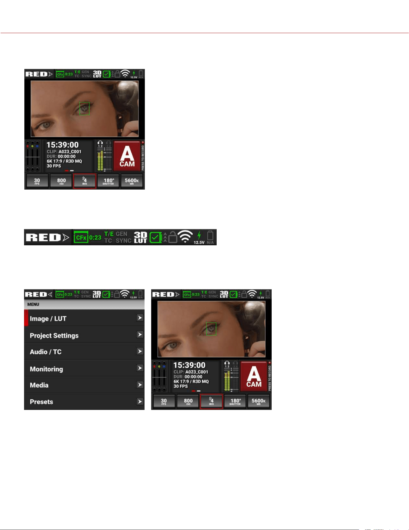
STATUS BAR
The top of the Onboard LCD screen displays the camera status bar.
The Status Bar contains the following button and icons:
Home / Menu Button
Media Status Icon
Temperature / Exposure Icon
Timecode Icon
Genlock Icon
SYNC Icon
Status Bar
3D LUT Icon
Network Activity Icon
LCD Lock Icon
Wi-Fi Icon
DC-In Icon
Battery Icon
HOME / MENU BUTTON
This button toggles the Onboard LCD display between the Home screen and the Menu screen. The arrow on the button
changes direction when toggled.
Home Screen: Menu Screen:
COPYRIGHT © 2023 RED.COM, LLC 955-0218, REV A | 21
KOMODO-X
®
OPERATION GUIDE
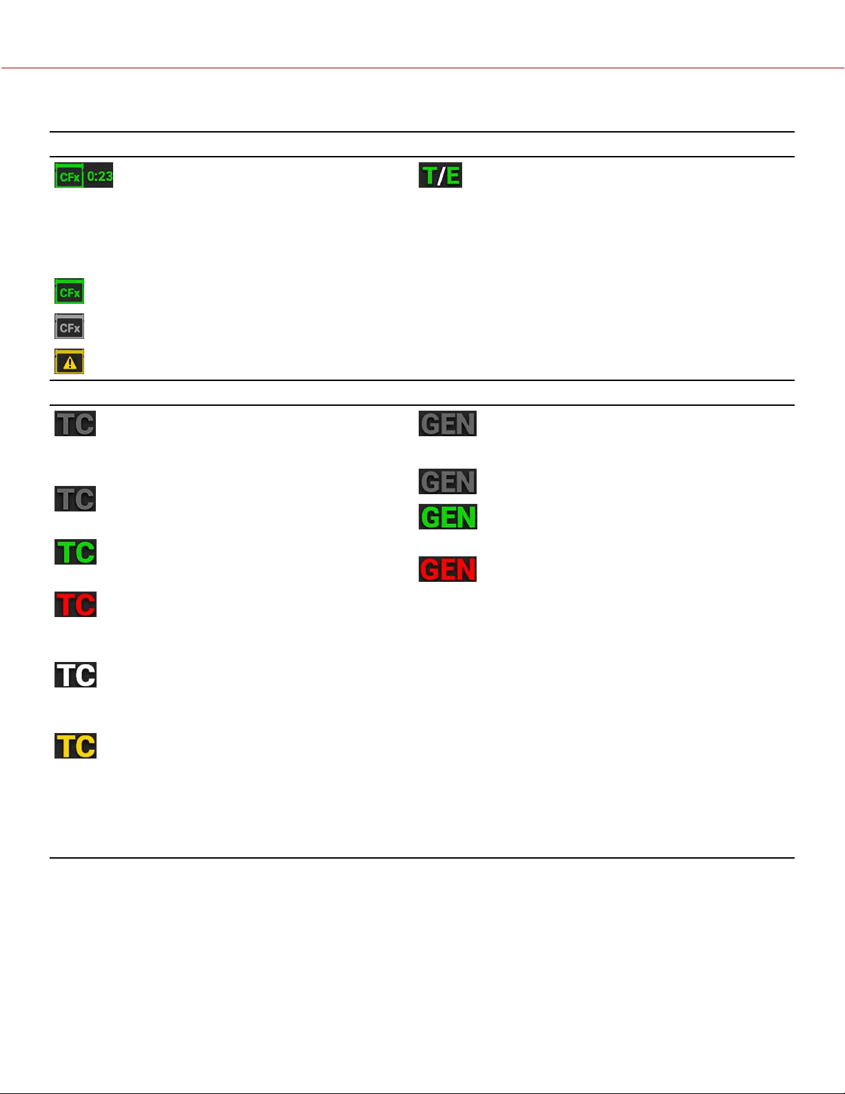
MEDIA STATUS ICON TEMPERATURE / EXPOSURE ICON
This icon displays the status of the CFexpress Type
B media card, and it displays the recording time
remaining for the current camera settings.
The status displayed includes:
Good
Missing
Incompatible
This icon displays the temperature (T) and exposure (E)
calibration indicators.
• When T is yellow or red, it indicates that the camera
requires sensor re-calibration at the current ambient
temperature.
• When E is yellow or red, it indicates that the camera
requires sensor re-calibration at the current shutter
speed.
Refer to Calibrating the Sensor.
TIMECODE ICON GENLOCK ICON
This icon indicates the state of the Timecode
generator connection.
Gray indicates that no Timecode generator
signal is detected.
Green indicates that the Timecode source is
connected and jammed.
Red indicates that the selected Timecode
Source is not present, or not jammed in the last 12
hours.
White indicates that the selected Timecode
source is not currently connected but was jammed
during the current camera boot.
Yellow indicates that the selected Timecode
source has not been jammed in current camera boot
but has been within the last 12 hours, or that
timecode source is cross-jammed (at a different
Project Time Base).
This icon indicates the state of the Genlock connection.
Gray indicates that no Genlock signal is detected.
Green indicates that the camera is receiving a
Genlock signal.
Red indicates that the camera is receiving and is
not locked to a Genlock signal.
COPYRIGHT © 2023 RED.COM, LLC 955-0218, REV A | 22
KOMODO-X
®
OPERATION GUIDE
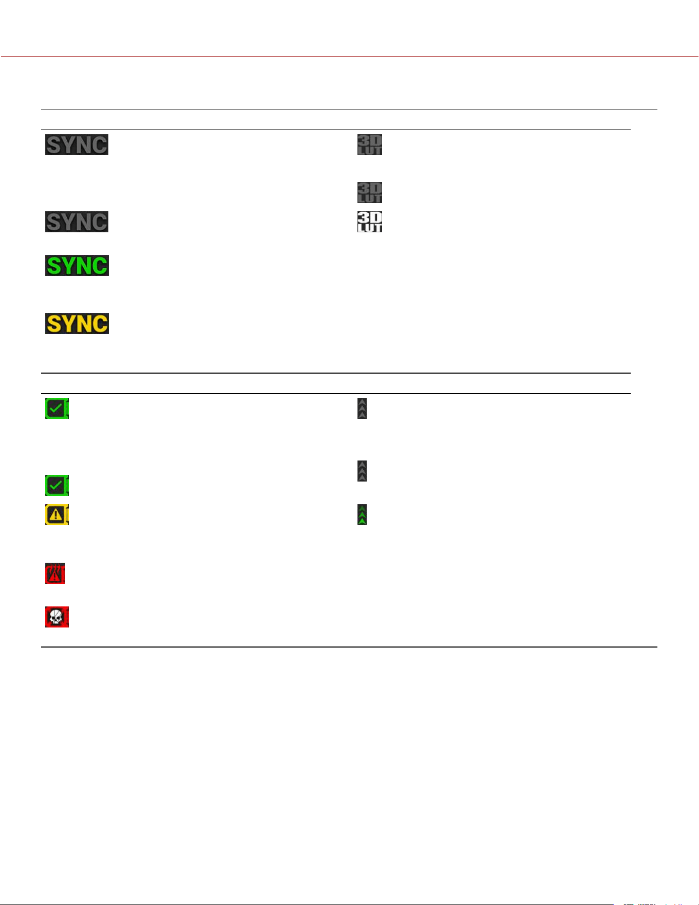
SYNC ICON 3D LUT ICON
This icon indicates that the Timecode and Genlock
signals are synchronized to the camera's frames per
second (FPS) settings.
Gray indicates that no synchronization is
detected.
Green indicates that the camera is
synchronized with the Timecode and Genlock
signals.
Yellow indicates that the camera is
synchronized using Genlock but not Timecode.
This icon indicates the activation status of 3D LUTs.
Gray indicates that no 3D LUTs are in use.
White indicates that the camera is using a 3D
LUT.
CAMERA STATUS ICON NETWORK ACTIVITY ICON
This icon indicates the state of the camera hardware.
The different icons and their corresponding status
include:
Good: Camera operating as expected.
Attention Required: Camera's calibration
requires attention or camera is nearing overheated
state.
Overheating: Camera has reached temperature
threshold and shut down is imminent.
Shutting Down: Camera is shutting down due to
overheating.
This icon indicates the state of FTPS or Cloud data
transfer.
Gray indicates that no network data transfer is
occurring.
Green indicates that the camera is transferring
FTPS or Cloud data.
COPYRIGHT © 2023 RED.COM, LLC 955-0218, REV A | 23
KOMODO-X
®
OPERATION GUIDE
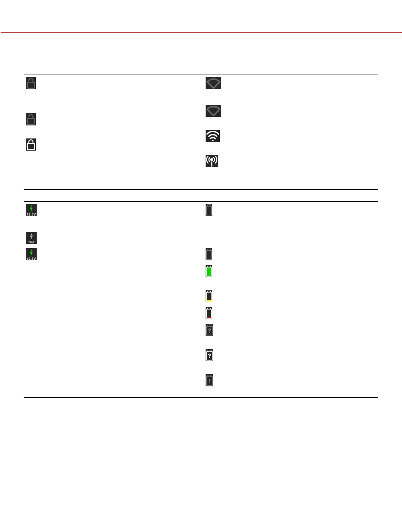
LCD LOCK ICON WI-FI ICON
This icon indicates the state of the Onboard LCD
Lock. The states include:
Gray and open indicates that the camera
Onboard LCD is unlocked.
White and closed indicates that the camera
Onboard LCD is locked.
This icon indicates the state of Wi-Fi connection.
Gray and empty indicates that no Wi-Fi signal is
detected.
White bars indicate that Wi-Fi signal is detected
(Infrastructure).
White antenna indicates that Wi-Fi signal is
broadcasting (Ad-hoc).
DC-IN ICON BATTERY ICON
This icon indicates the state of DC power connection.
Gray indicates that no DC power is connected.
Green indicates that the camera is receiving DC
power and the voltage number is displayed.
This icon indicates the state of the battery connection
and charge level. When the voltage is low, it displays the
voltage in red.
Gray indicates that no battery is connected.
White indicates that the battery is connected and
green shows the relative level of charge remaining.
Yellow indicates 10 minutes of power remaining.
Red indicates less then 5 minutes of power remaining.
Gray question mark indicates no communication with
the battery and no power.
White question mark indicates no communication with
the battery and power.
Gray exclamation point indicates error communicating
with the battery and no power.
COPYRIGHT © 2023 RED.COM, LLC 955-0218, REV A | 24
KOMODO-X
®
OPERATION GUIDE
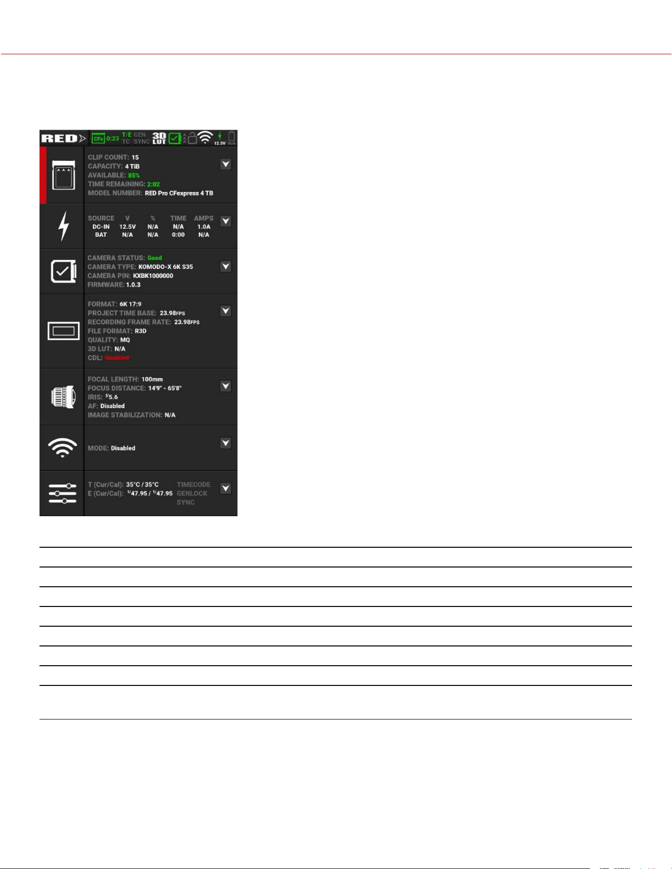
STATUS PAGE
The Status page contains camera status information and shortcuts to the associated camera menus:
The camera status and menu shortcuts include:
ITEM DETAILS
Media Displays the media status and a link to the Media Menu
Power Displays the power status and a link to the Power settings menu
System Status Displays the camera temperature status and a link to the System Status menu
Project Settings Displays the project status and a link to the Project Settings Menu
Lens Displays the lens status and a link to the Lens settings menu
Wi-Fi Displays the communication status and a link to the Wi-Fi settings menu
Maintenance Displays the Temperature and Exposure calibration, the external connection status, and a link
to the Maintenance Menu
COPYRIGHT © 2023 RED.COM, LLC 955-0218, REV A | 25
KOMODO-X
®
OPERATION GUIDE
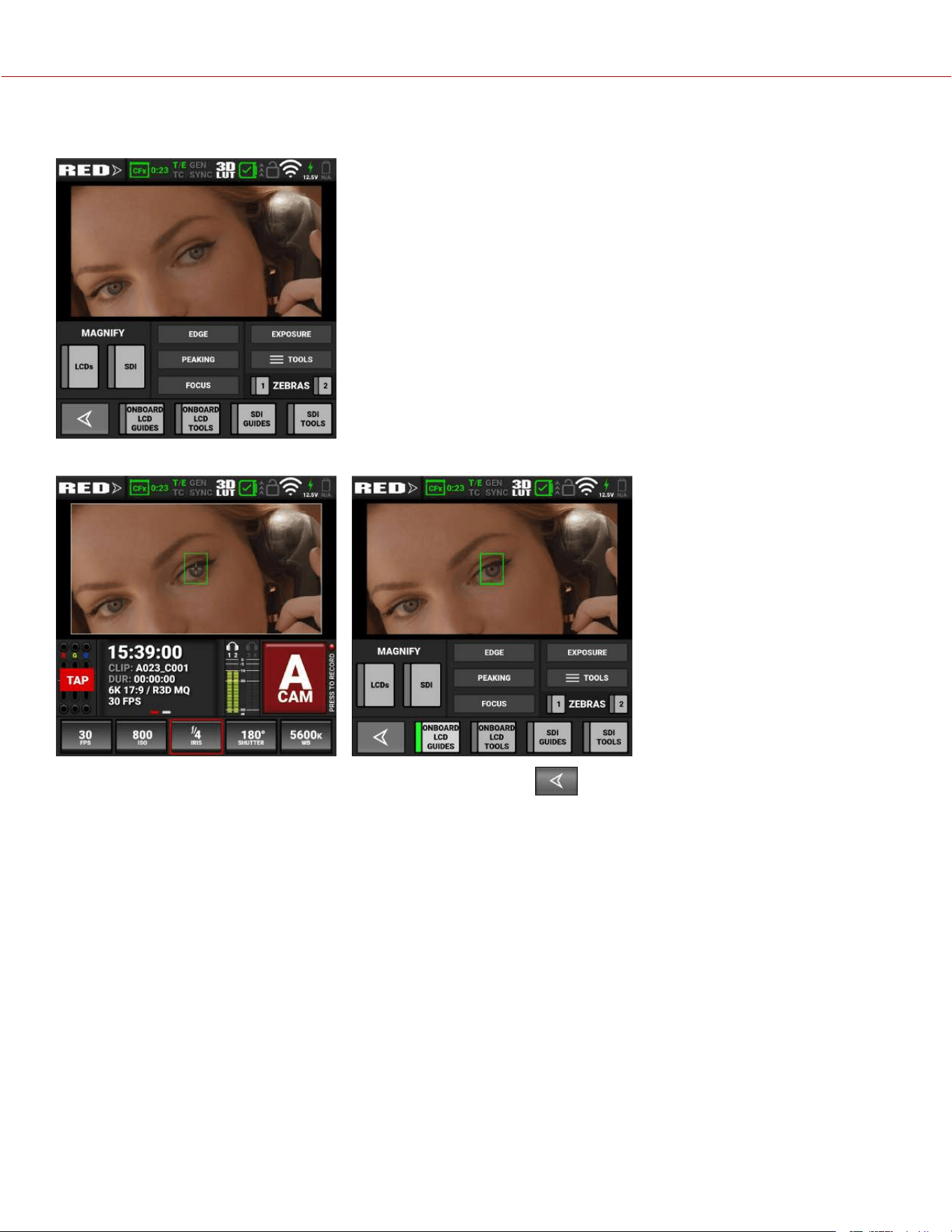
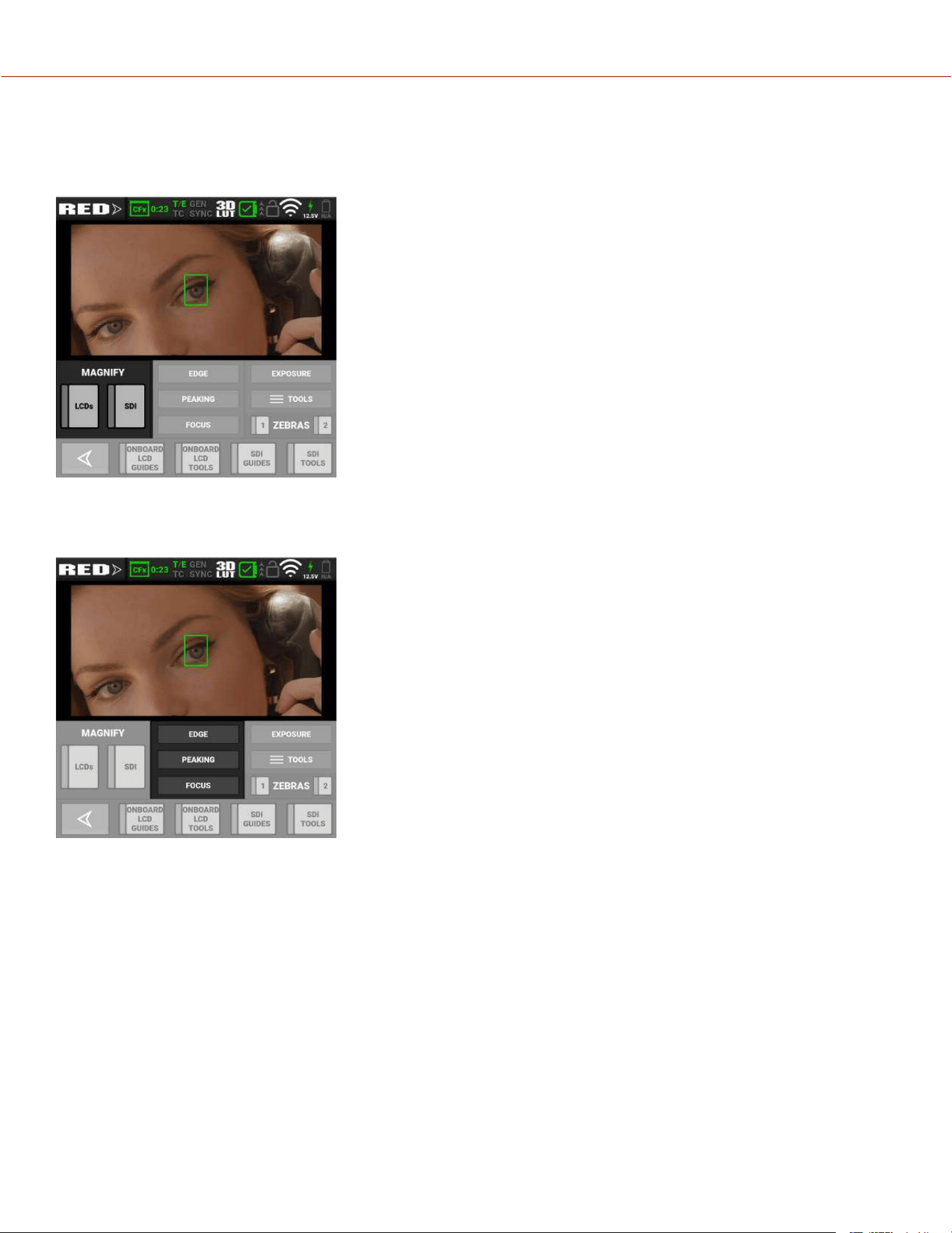
MONITORING TOOLS
Open the Monitoring tools by tapping on the Exposure section of the Onboard LCD home page.
Return to the Onboard LCD home page by tapping the arrow button
The Monitoring tools provide an easy way to toggle many of the monitoring features on and off.
When the features are selected, the buttons indicate the selection.
COPYRIGHT © 2023 RED.COM, LLC 955-0218, REV A | 26
KOMODO-X
®
OPERATION GUIDE
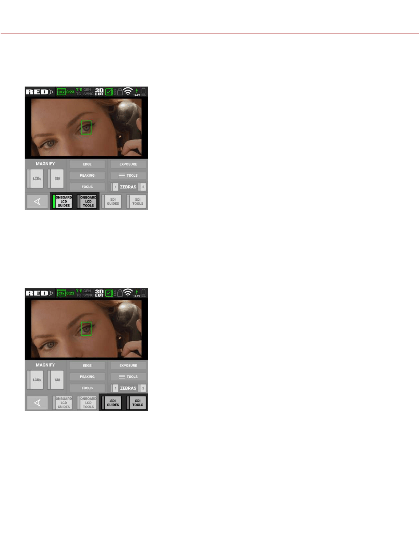
ONBOARD LCD SWITCHES
The Onboard LCD switches allow you to view or hide the enabled LCD monitor Guides and Tools on the Onboard LCD
screen.
When the switches are selected, the gray bar turns green on the left side of the switch.
The Onboard LCD Guides switch displays the Monitoring Guides (frame guides and center guide) on the Onboard LCD.
The Onboard LCD Tools switch displays the Monitoring Tools (false color, peaking, zebra) on the Onboard LCD and on
Live Stream.
SDI SWITCHES
The SDI switches allow you to view or hide the enabled SDI monitor Guides and Tools on the Onboard LCD screen.
When the switches are selected, the gray bar turns green on the left side of the switch.
The SDI Guides switch displays the Monitoring Guides (frame guides and center guide) on the SDI output.
The SDI Tools switch displays the Monitoring Tools (false color, peaking, zebra) on the SDI output.
COPYRIGHT © 2023 RED.COM, LLC 955-0218, REV A | 27
KOMODO-X
®
OPERATION GUIDE
MAGNIFY
The Magnify section allows you to enable or disable magnification on the camera's LCDs (Onboard LCD and Top LCD)
and the SDI monitor output. When the switches are selected, the gray bar turns green on the left side of the switch.
FOCUS
The Focus section allows you to enable or disable one of the focus tools. The focus tool button you select will turn red.
For information about using the Focus tools, refer to Tools.
COPYRIGHT © 2023 RED.COM, LLC 955-0218, REV A | 28
KOMODO-X
®
OPERATION GUIDE
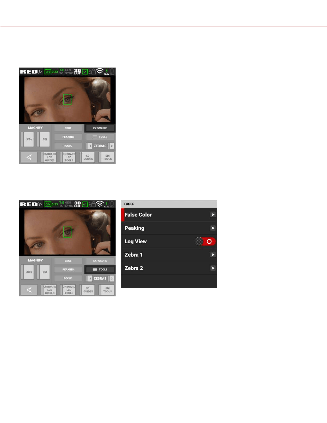
EXPOSURE
The Exposure section allows you to enable or disable one of the exposure tools. The Exposure tool button you select
will turn red.
For information about using the Exposure tools, refer to Tools.
TOOLS
The Tools section allows you to open the Monitor Tools menu.
For information about the Monitor Tools menu, refer to Tools.
COPYRIGHT © 2023 RED.COM, LLC 955-0218, REV A | 29
KOMODO-X
®
OPERATION GUIDE
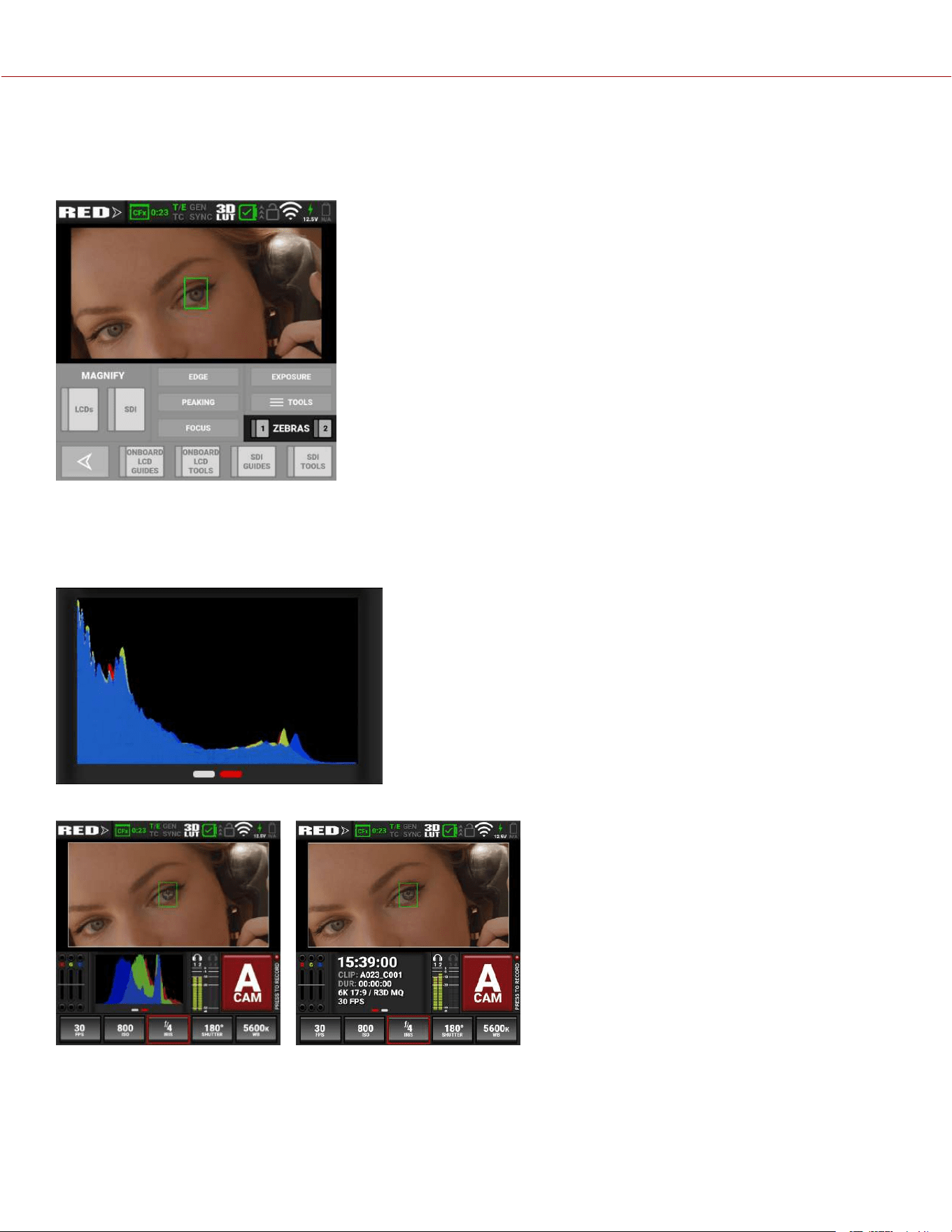
ZEBRA
The Zebra section allows you to enable or disable the Zebra 1 and Zebra 2 modes. When the modes are selected, the
gray bar turns green on the left side of the switch.
For information about using the two Zebra modes, refer to Zebra 1 and Zebra 2.
HISTOGRAM
NOTE: The Histogram feature is disabled on Monochrome cameras.
Tap the histogram area to toggle between the Histogram display and the Media display.
COPYRIGHT © 2023 RED.COM, LLC 955-0218, REV A | 30
KOMODO-X
®
OPERATION GUIDE
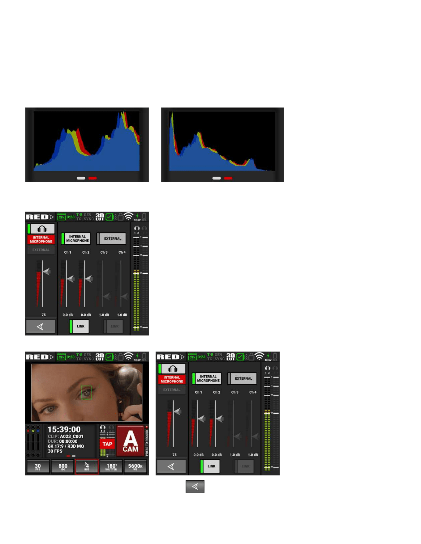
The Histogram area of the LCD home page displays an RGB exposure distribution histogram of the final image as it
appears on screen. The histogram takes into account exposure elements such as ISO, LUTs, and white balance.
The histogram displays the darkest image elements at the far left, the midtones in the middle, and the lightest image
elements at the far right. This provides a quick visual tool you can use to determine your overall image exposure levels.
Overexposed Example Underexposed Example
AUDIO TOOLS
Open the Audio tools by tapping on the Audio section of the LCD home page.
Return to the LCD home page by tapping the arrow .
The Audio tools provide an easy way to control many of the audio features.
When the features are selected, the buttons indicate the selection.
COPYRIGHT © 2023 RED.COM, LLC 955-0218, REV A | 31
KOMODO-X
®
OPERATION GUIDE
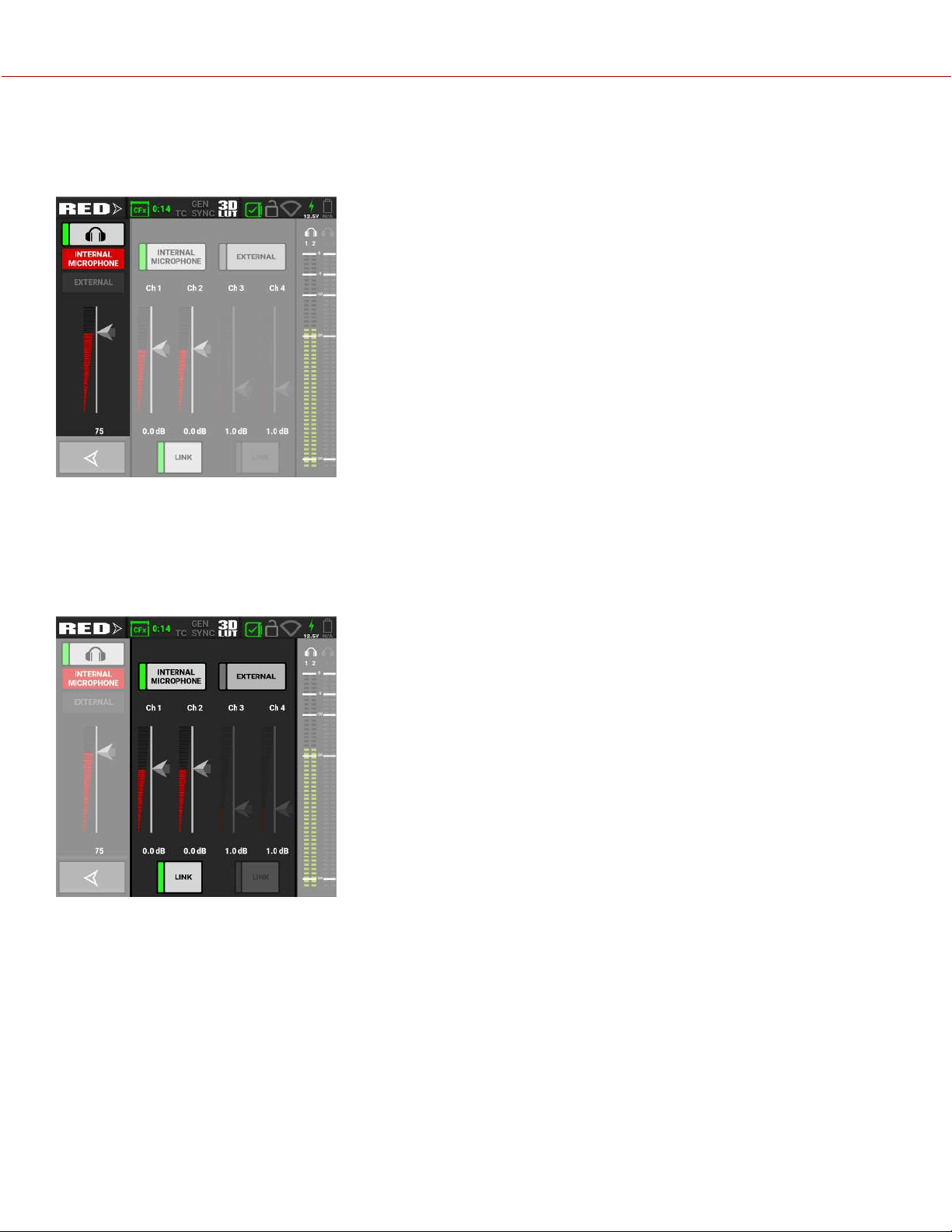
HEADPHONE
The headphone section allows you to enable/disable the headphone output, to select input from Internal Microphone, or
External, and to adjust the headphone volume with a slider.
AUDIO SOURCE
The Audio Source section allows you to select the audio source the camera will record to the clip. You can select
Internal Microphone, External, both, or none. Use the sliders to adjust the gain for each channel. You can use the Link
button to link channels 1 and 2, or to link channels 3 and 4. This allows you to adjust both of the internal or external
channels together.
COPYRIGHT © 2023 RED.COM, LLC 955-0218, REV A | 32
KOMODO-X
®
OPERATION GUIDE
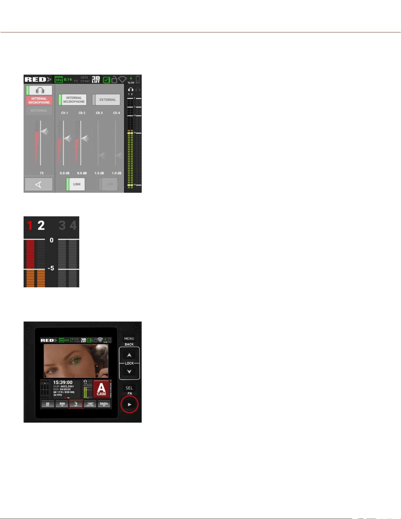
AUDIO VU METER
The Audio VU Meter section displays the audio input received by the camera from the four channels.
As the input increases, the level indicator changes from green to yellow to orange to red. When the audio input clips,
the channel number at the top of the VU meter turns red:
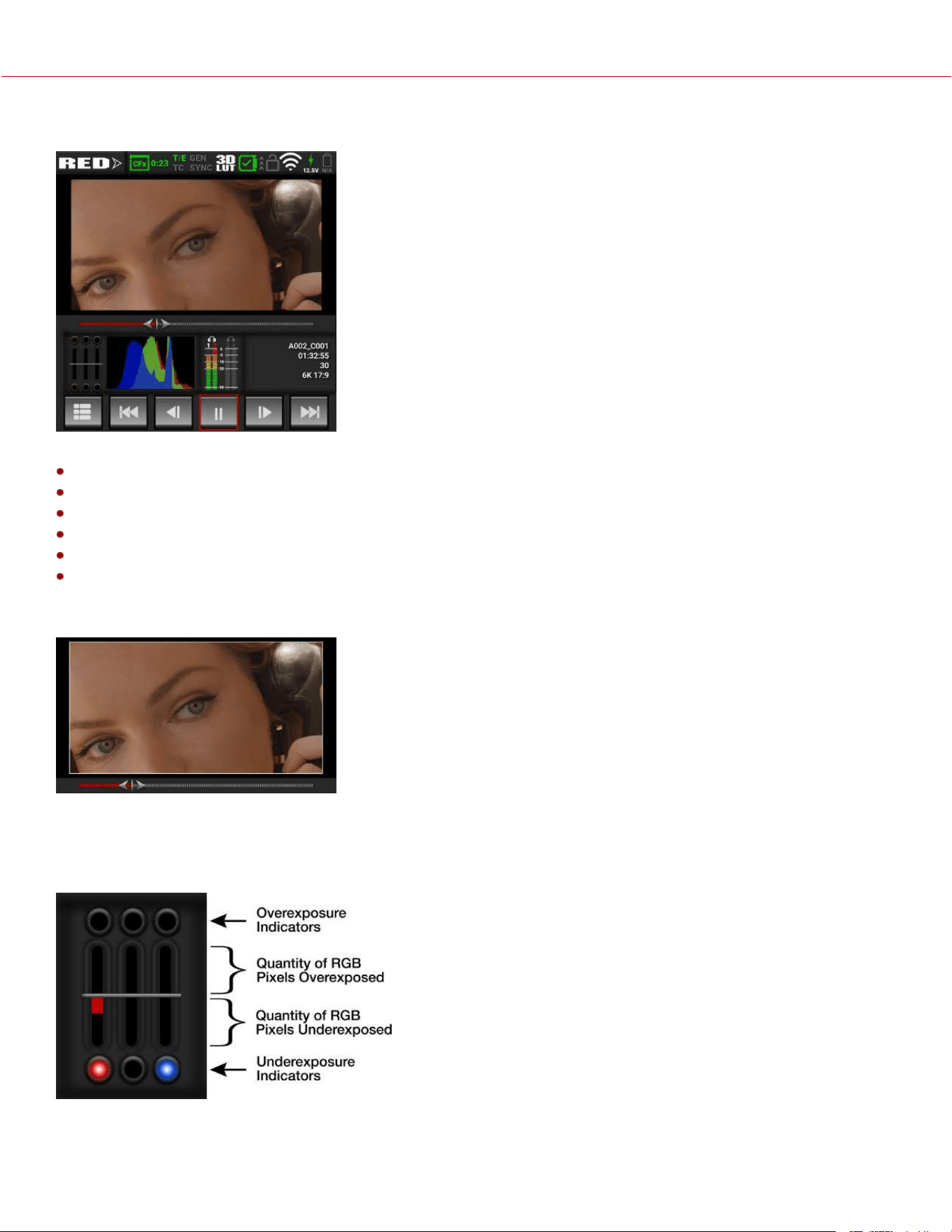
PLAYBACK
When you press on the Playback button, the Onboard LCD Touchscreen displays the Playback screen.
To close the Playback screen, press the Playback button.
NOTE: When you open playback, it disables many of the menu settings.
COPYRIGHT © 2023 RED.COM, LLC 955-0218, REV A | 33
KOMODO-X
®
OPERATION GUIDE
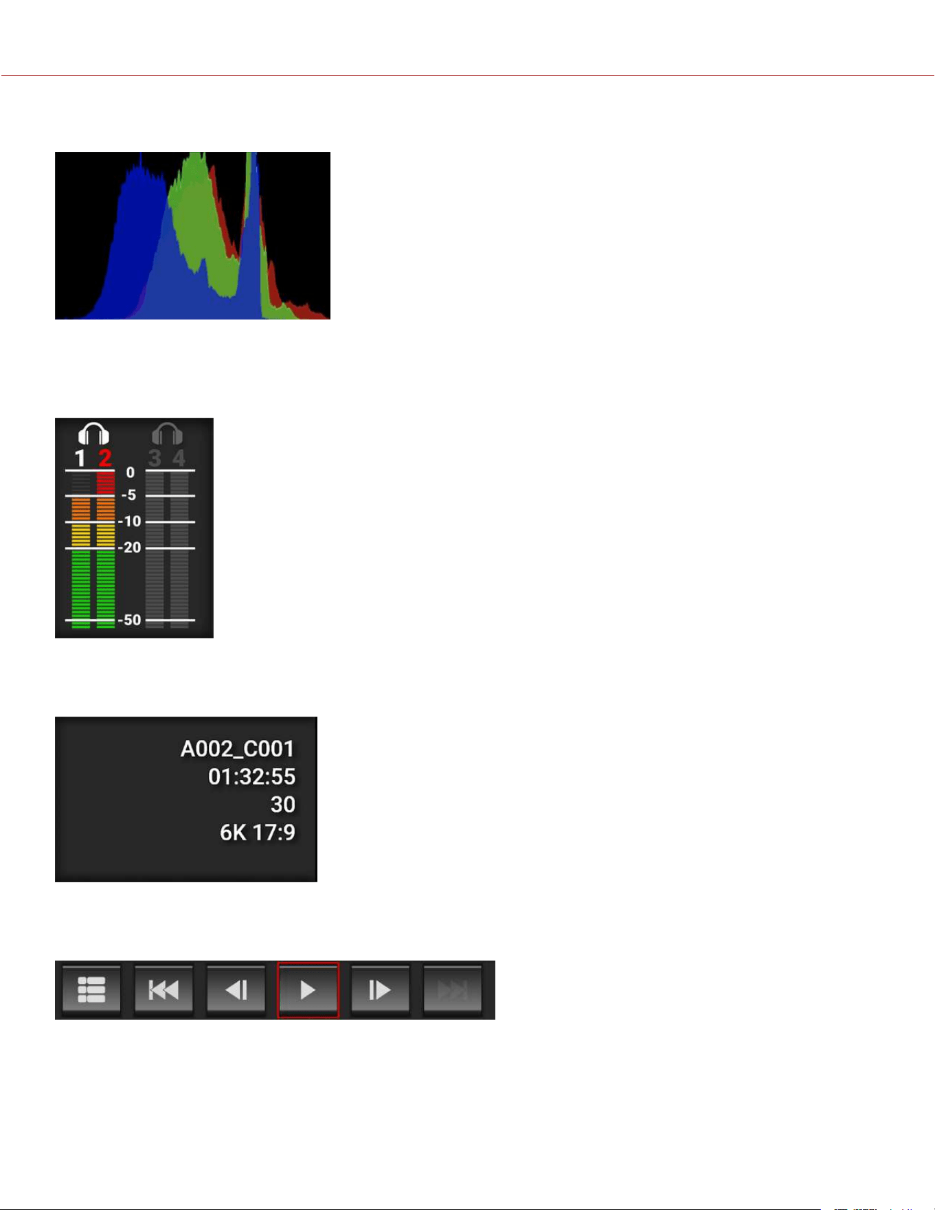
PLAYBACK SCREEN
The Playback screen displays the clip image along with the following:
Clip Slider
RGB Exposure
Histogram
Audio VU Meters
Clip Information
Playback Screen Buttons
CLIP SLIDER
Use your finger to move forward and backward through the frames by swiping the image to the left and the right. The
Clip Slider shows where in the timeline the displayed frame is located in the clip.
RGB EXPOSURE
RGB Exposure displays the exposure levels of the separate RGB channels and indicates when a channel is
underexposed or overexposed. This meter measures the raw image data regardless of the ISO and LUT settings.
COPYRIGHT © 2023 RED.COM, LLC 955-0218, REV A | 34
KOMODO-X
®
OPERATION GUIDE
HISTOGRAM
The histogram displays the darkest image elements at the far left, the midtones in the middle, and the lightest image
elements at the far right. This gives you a quick way to view your overall image exposure levels.
AUDIO VU METERS
The Audio VU meters display the audio levels in the played clip.
CLIP INFORMATION
The Clip Information displays the name, duration, time base, and format of the clip.
PLAYBACK SCREEN BUTTONS
With the Playback screen buttons you can view the Clip list, move one clip back, move one frame back, play/pause,
move one frame forward, and move one clip forward.
COPYRIGHT © 2023 RED.COM, LLC 955-0218, REV A | 35
KOMODO-X
®
OPERATION GUIDE
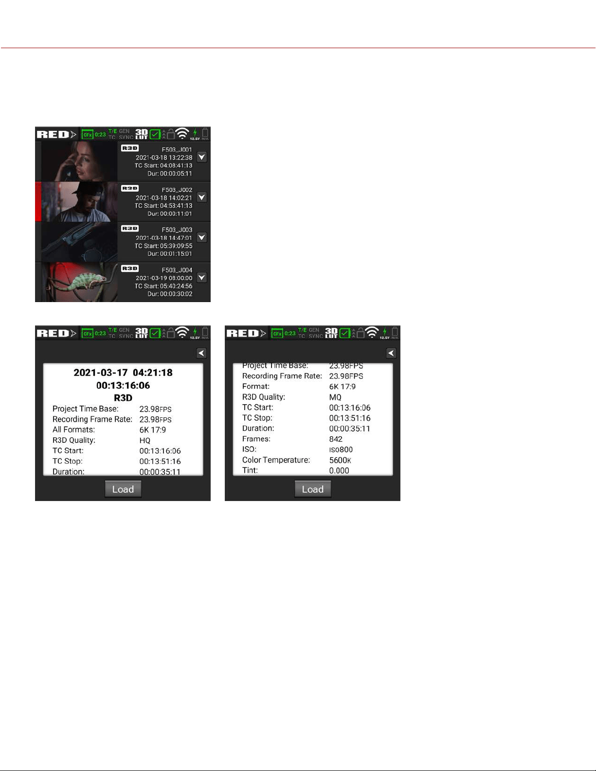
CLIP LIST
The Clip List button displays the list of clips recorded on the media card.
Each clip displays the first frame of the clip, the clip information, and the clip file format.
Swipe up and down to scroll through the list of clips. Tap the down arrow to open the clip information screen.
When you tap the Load button, the camera loads the clip to the Playback screen.
COPYRIGHT © 2023 RED.COM, LLC 955-0218, REV A | 36
KOMODO-X
®
OPERATION GUIDE

COPYRIGHT © 2023 RED.COM, LLC 955-0218, REV A | 37
4. MENUS
This section describes the menus and sub-menus for the camera. To access the menus, navigate to a menu item from
the Onboard LCD Touchscreen.
MENUS DETAILS
Image / LUT Menu ISO, Shutter, White Balance, Output Color Space, Output Tone Map, Highlight Roll-Off,
Display Preset, 3D LUT, CDL, Exposure Adjust
Project Settings Menu Format, Recording Frame Rate, Project Time Base, File Format, R3D Quality,
ProRes Resolution, ProRes Codec, ProRes Color Profile, Pre-Record, Recording Mode,
Timelapse, Frame Limit, Slate
Audio / TC Menu Audio Source, Internal Mic, External Audio, Headphone, Timecode Source,
Auto-Jam Toggle, Jam Timecode to TOD, Manual Timecode, Timecode Display Mode
Monitoring Menu Onboard LCD, Top LCD, SDI, Live Stream, Tools, Guides
Media Menu Eject, Media Info, Secure Format
User Settings Menu Create Presets and assign User Button functions
Autofocus Menu Enable AF, Mode, Size, Position, AF Toggle
Communication Menu Camera, Connections (USB-C, Wi-Fi, Serial), Clients & Services (FTPS, PTP), Cloud
Upload (Frame.io, AWS S3)
System Settings Menu Date / Time, Licenses, Lens, Power, Sensor, Indicators, GPO, Status Settings, System
Status
Language Menu English, Chinese, French, German, Japanese, Spanish
Maintenance Menu Calibrate, Calibration, Save Log, Reset Defaults, Factory Reset, Upgrade FW
KOMODO-X
®
OPERATION GUIDE
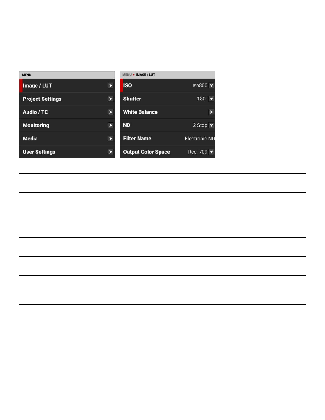
IMAGE / LUT MENU
The Image / LUT menu contains the settings you use to configure your image.
From the Onboard LCD touchscreen menu, tap Image / LUT:
Use the Image / LUT menu to configure the camera's image and lookup table (LUT) settings:
ITEM DETAILS
ISO Adjusts the image’s brightness in the monitoring path
Shutter Adjusts the amount of time the sensor is exposed to light
White Balance Adjusts the colors to compensate for the light source temperature
ND When attached, you can adjust the ND value for the RF to PL Adapter w/
Electronic ND
Filter Name When attached, this displays the name of the PL filter.
Output Color Space Adjusts on-set working color space
Output Tone Map Adjusts the image contrast
Highlight Roll-Off Adjusts image highlight compression
Display Preset Select the displayed preview image gamma for the SDI port
3D LUT Manage the camera's look up tables (LUTs).
CDL Opens the Color Decision List (CDL) menu
Exposure Adjust Manually fine-tunes the midtone exposure level
COPYRIGHT © 2023 RED.COM, LLC 955-0218, REV A | 38
KOMODO-X
®
OPERATION GUIDE
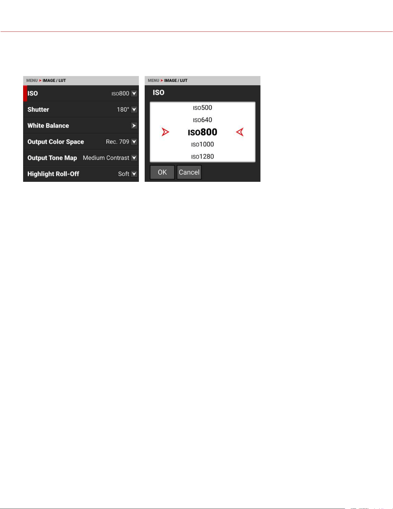
ISO
Use the ISO setting to adjust the image’s exposure in the monitoring path.
The ISO range is ISO 250 to ISO 12,800. The default ISO is ISO 800 for color and ISO 2000 for Monochrome.
Higher ISO values create brighter images in the monitor path, and lower ISO values create darker images in the monitor
path.
When you record, the ISO settings are stored as metadata and you can adjust them non-destructively in post-
processing with REDCINE-X PRO or other editing tools that support R3D files.
RED recommends setting the ISO to the default of 800, then adjusting the aperture and lighting to match. You can
adjust the ISO later for fine-tuning.
NOTE: When you set the File Format to ProRes, the ISO is baked-in the image.
COPYRIGHT © 2023 RED.COM, LLC 955-0218, REV A | 39
KOMODO-X
®
OPERATION GUIDE
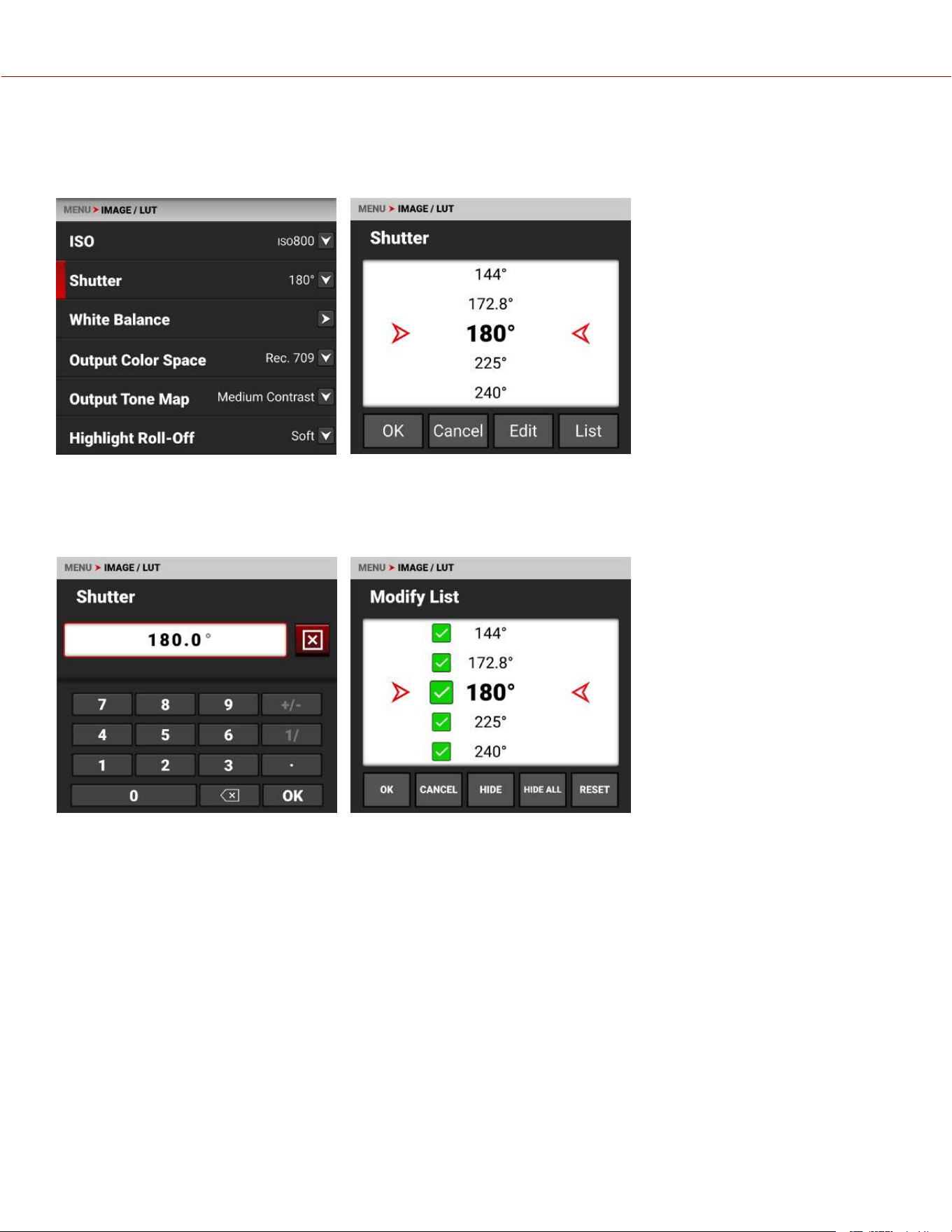
SHUTTER
Use Shutter to select the exposure time (shutter speed / shutter angle). The camera allows you to change the shutter
settings while recording.
You can switch between Angle and Time settings by holding down the Onboard LCD Shutter quick setting button on
the main menu, or by changing the Shutter Display mode in the Status Settings menu.
You can tap Edit to change the Shutter
menu values manually.
You can tap List to choose which values you
want to display on the menu list.
COPYRIGHT © 2023 RED.COM, LLC 955-0218, REV A | 40
KOMODO-X
®
OPERATION GUIDE

SHUTTER ANGLE
Enter the exposure value as a shutter angle (xx°). The shutter angle range is 1° to 360°. The default shutter angle is
180°. Click Edit to enter an exact shutter angle or shutter speed.
EXPOSURE CONVERSIONS
The table below lists common shutter angle and shutter speed equivalents. The calculations in the table use a recording
frame rate of 23.98 fps.
SHUTTER
ANGLE (°)
SHUTTER SPEED
(1/XX SEC)
SHUTTER
ANGLE (°)
SHUTTER SPEED
(1/XX SEC)
360˚ 1/23.98 105˚ 1/82.20
288˚ 1/29.97 90˚ 1/95.90
270˚ 1/31.97 72˚ 1/119.88
240˚ 1/35.96 45˚ 1/191.81
225˚ 1/38.36 22.5˚ 1/383.62
180˚ 1/47.95 11.2˚ 1/770.66
172.8˚ 1/49.95 8.6˚ 1/1003.65
144˚ 1/59.94 4˚ 1/2157.84
135˚ 1/63.95 1˚ 1/8000 (max)
120˚ 1/71.93
SHUTTER SPEED
Enter the exposure value as a shutter speed (1/xx sec).
The slowest shutter speed is 1/(recording frame rate). For example, if the recording frame rate is 23.98 fps, the slowest
available shutter speed is 1/23.98 sec. The slowest available shutter speed in the camera is 1/5.99 sec when the
recording frame rate is set to 5.99 fps. The fastest shutter speed is 1/8000 sec. The default shutter speed is 1/47.95
sec.
CONVERT SHUTTER SPEED TO SHUTTER ANGLE
Shutter Angle = (Shutter Speed x Frame Rate x 360)
Example: (1/47.95 x 23.98 x 360) = 180
CONVERT SHUTTER ANGLE TO SHUTTER SPEED
Shutter Speed = 1/(Frame Rate x 360/Angle)
Example: 1/(23.98 x 360/180) = 1/47.95
COPYRIGHT © 2023 RED.COM, LLC 955-0218, REV A | 41
KOMODO-X
®
OPERATION GUIDE
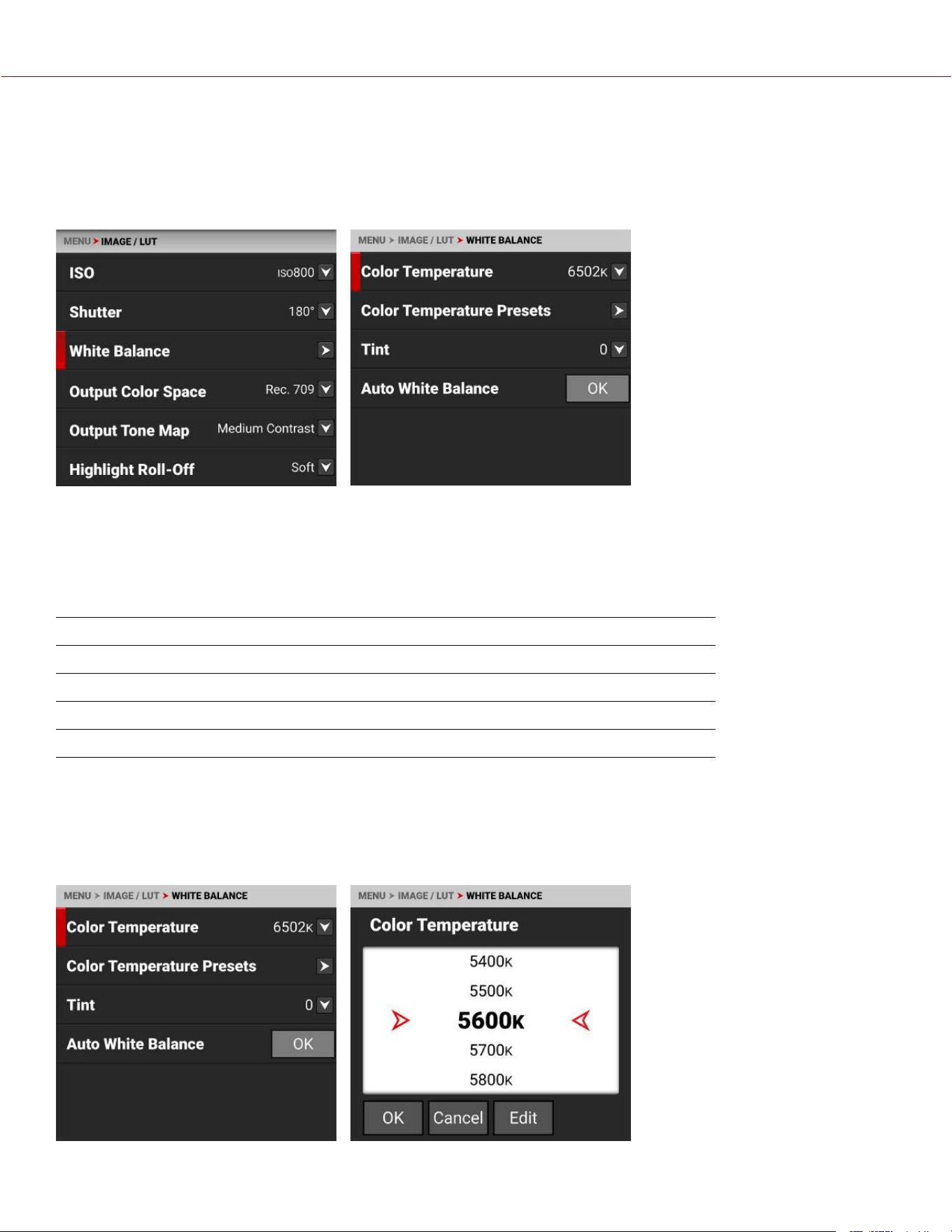
WHITE BALANCE
Use the White Balance menu to adjust the Color Temperature, Color Temperature Presets, Tint and execute the Auto
White Balance.
NOTE: Color temperature is disabled on Monochrome cameras.
You can switch between Kelvin and Presets by holding down the Onboard LCD WB quick setting button on the main
menu, or by changing the White Balance List mode in the Status Settings menu.
When shooting in R3D format, the camera stores white balance as metadata, which you can adjust non-destructively in
post-production after filming.
Use the White Balance menu to configure the color temperature and tint settings for your image:
ITEMS DETAILS
Color Temperature Image color temperature correction
Color Temperature Presets Tap a button to select a preset color temperature
Tint Adjust magenta-green color component
Auto White Balance The camera automatically sets the color temperature and tint
NOTE: When you set the File Format to ProRes, White Balance is baked-in the image.
COLOR TEMPERATURE
Use Color Temperature to adjust the image's color temperature in Kelvin units (K) or by selecting presets.
NOTE: Color temperature is disabled on Monochrome cameras.
COPYRIGHT © 2023 RED.COM, LLC 955-0218, REV A | 42
KOMODO-X
®
OPERATION GUIDE
When the image's light source color temperature is warm, you can compensate by setting the camera to a warmer color
temperature. When the image's light source color temperature is cool, you can compensate by setting the camera to a
cooler temperature.
The color temperature range is 1,700 K to 10,000 K. The default color temperature is 5600 K.
When the White Balance List Mode (refer to Status Settings) is set to Presets, the Color Temperature menu list uses the
preset temperatures instead of the Kelvin temperatures.
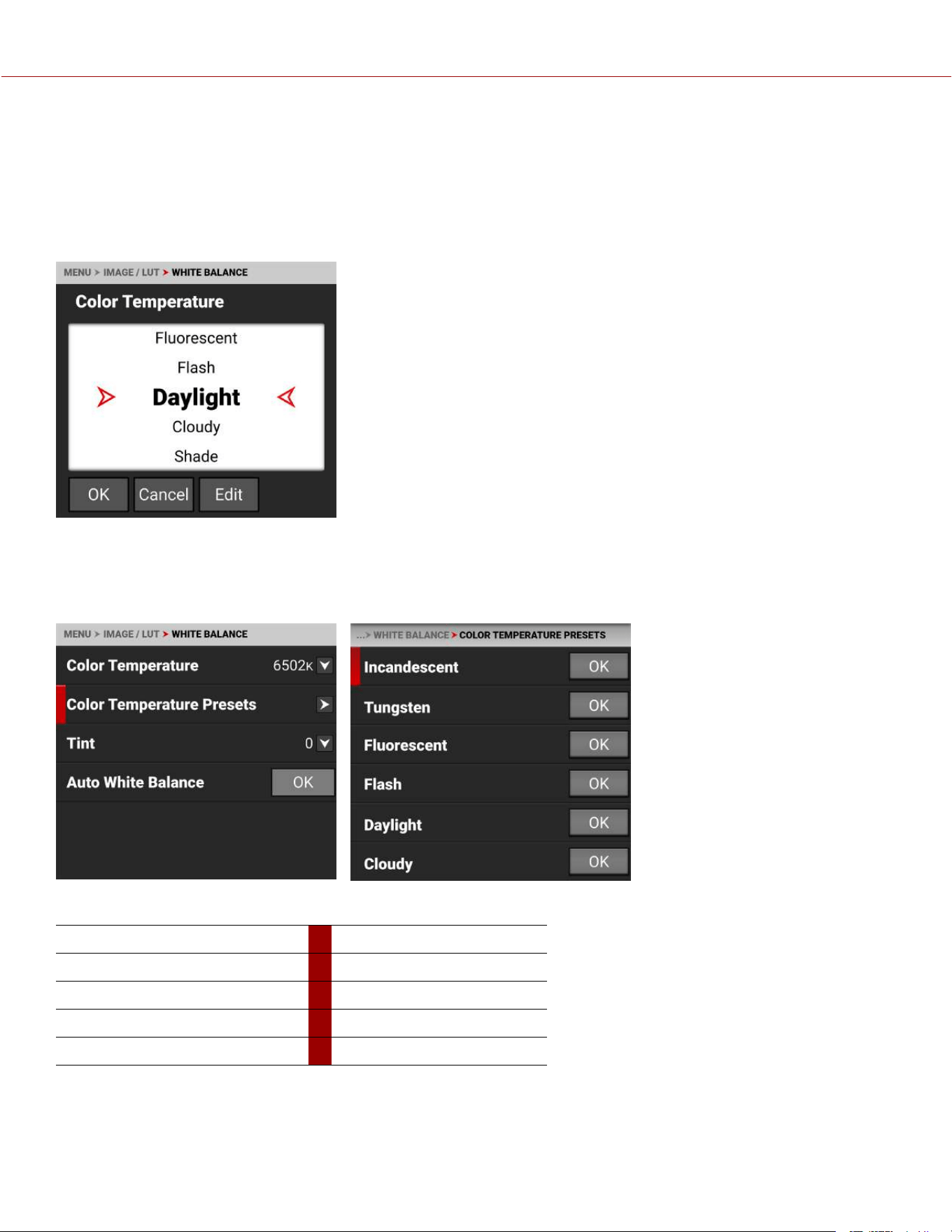
COLOR TEMPERATURE PRESETS
Use Color Temperature Presets to select a pre-configured color temperature.
NOTE: Color temperature is disabled on Monochrome cameras.
The color temperature presets you can select include:
ITEMS DETAILS ITEMS DETAILS
Incandescent 2800 K Daylight 5600 K
Tungsten 3200 K Cloudy 7500 K
Fluorescent 4500 K Shade 9000 K
Flash 5500 K
COPYRIGHT © 2023 RED.COM, LLC 955-0218, REV A | 43
KOMODO-X
®
OPERATION GUIDE
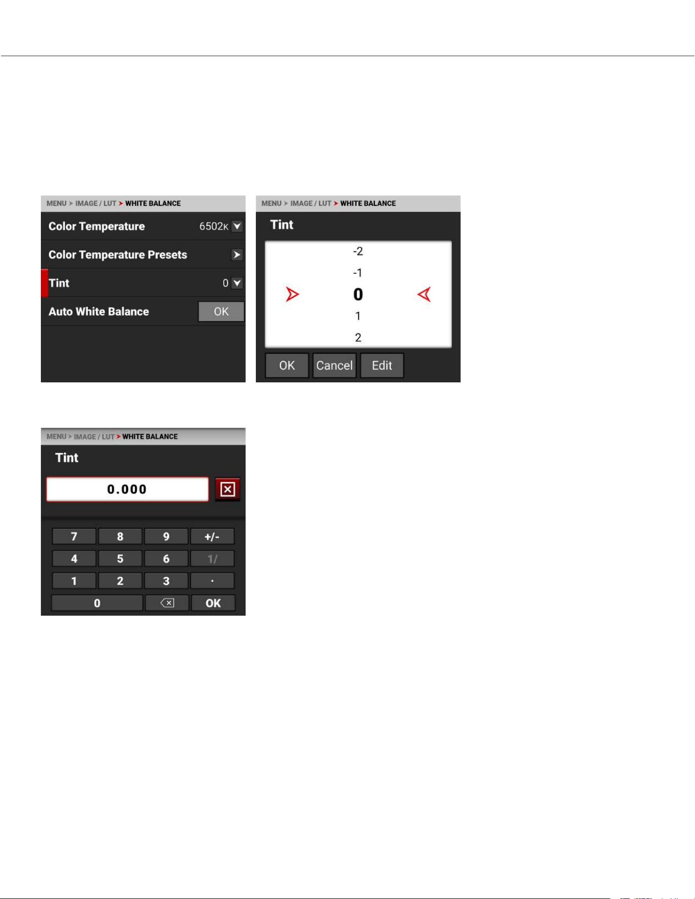
TINT
Use Tint to adjust the image's color tint.
NOTE: Tint is disabled on Monochrome cameras.
Color temperature calculations assume a pure light source that may not be true in the specific scene the camera is
imaging. To compensate for any residual colorcast, the Tint setting adjusts the RGB color balance with a compensating
magenta-green color component.
Tint range is –100 to 100. The default Tint setting is 0.
Use Edit to open the keypad screen where you can enter a specific Tint value.
COPYRIGHT © 2023 RED.COM, LLC 955-0218, REV A | 44
KOMODO-X
®
OPERATION GUIDE
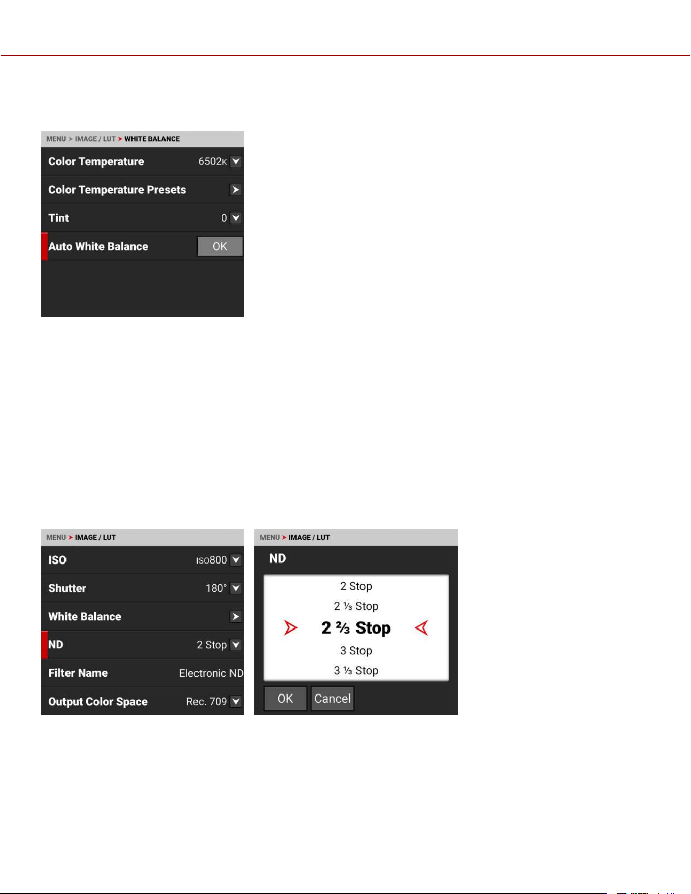
AUTO WHITE BALANCE
Use Auto White Balance to use the camera's automatic white balance adjustment.
When shooting in R3D format, the camera stores white balance as metadata, which you can adjust non-destructively in
post-production after filming.
To use Auto White Balance:
1. Place an 18% gray chart in the center of the image under the correct exposure.
2. From the White Balance menu tap OK next to Auto White Balance.
3. The camera automatically sets the color temperature and tint settings.
NOTE: Place the chart in the same location as your subject, and illuminate it with the same lighting. Make sure that you
center the chart, and that it fills at least 25% of the sensor area.
ND
When the RF to PL Adapter w/ Electronic ND is attached, and the Electronic ND filter is inserted, you can use this menu
to select the density of the ND filter.
The ND filter range is 2-7 stops or 0.6 to 2.1 density. From the Status Settings menu, you can use the ND Display Mode
submenu to select Stops or Density units, and you can use the ND Increments submenu to select the size of the
NDincrements displayed on the camera (refer to Status Settings for more information).
COPYRIGHT © 2023 RED.COM, LLC 955-0218, REV A | 45
KOMODO-X
®
OPERATION GUIDE
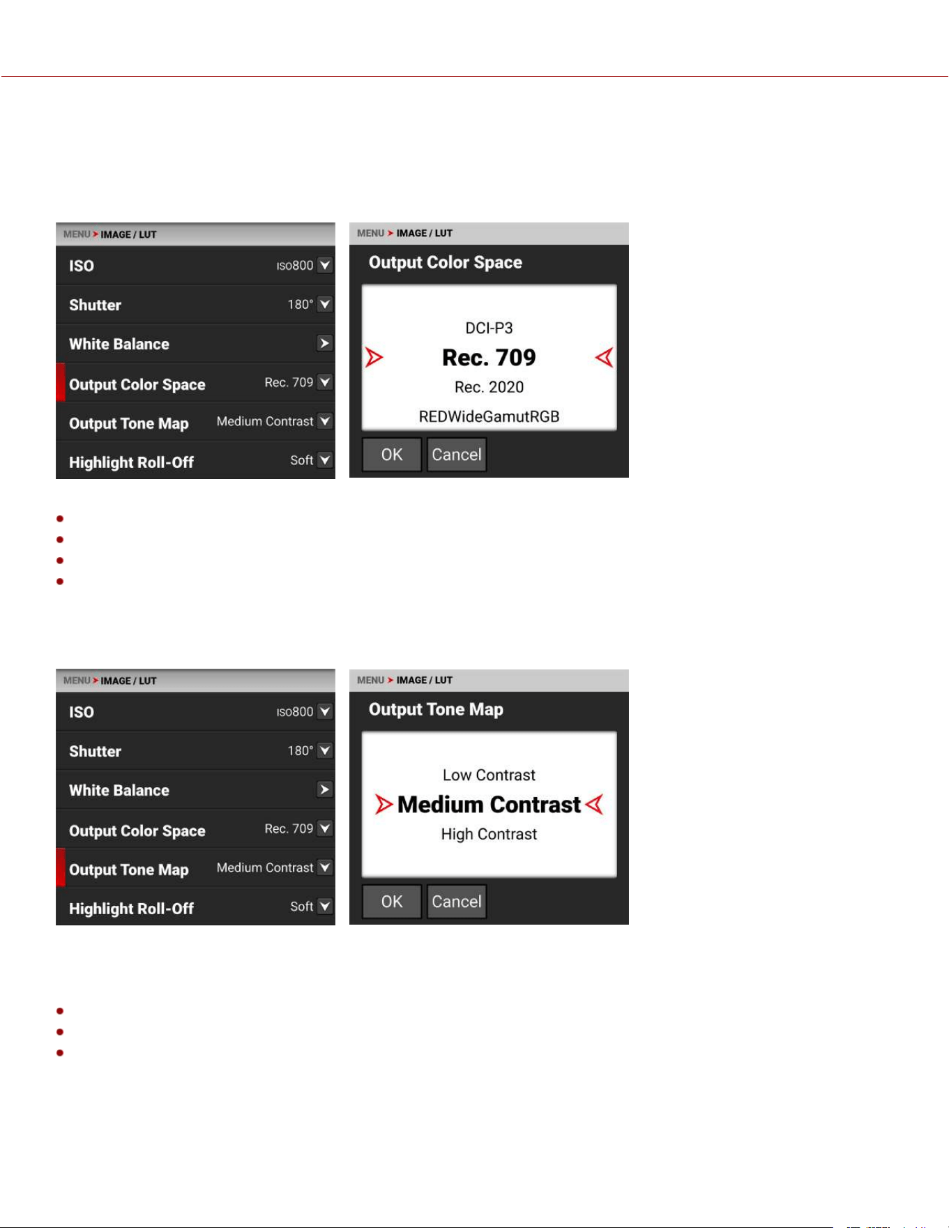
OUTPUT COLOR SPACE
Use Output Color Space to select the desired color space associated with the clip. When the camera file format is R3D,
it saves this color space as metadata, which you can adjust in post-processing. When the camera uses the ProRes file
format, and the ProRes Color Profile is Image/LUT, the camera bakes the color space in the resulting image.
The Output Color Space selections include:
DCI-P3 - Digital Cinema Initiatives theater projector standard color space
Rec. 709 - Standard Color Space for HDTV (default)
Rec. 2020 - Standard Color Space for UHD and HDR
REDWideGamutRGB - Color space encompassing all of the colors the RED camera can generate without clipping.
OUTPUT TONE MAP
Use Output Tone Map to adjust the image contrast when displaying the camera output.
When shooting in R3D format, the camera stores this as metadata, which you can adjust non-destructively in post-
production after filming.
The Output Tone Map selections include:
Low Contrast - Low contrast is applied to the image
Medium Contrast - Medium contrast is applied to the image (default)
High Contrast - High contrast is applied to the image.
COPYRIGHT © 2023 RED.COM, LLC 955-0218, REV A | 46
KOMODO-X
®
OPERATION GUIDE
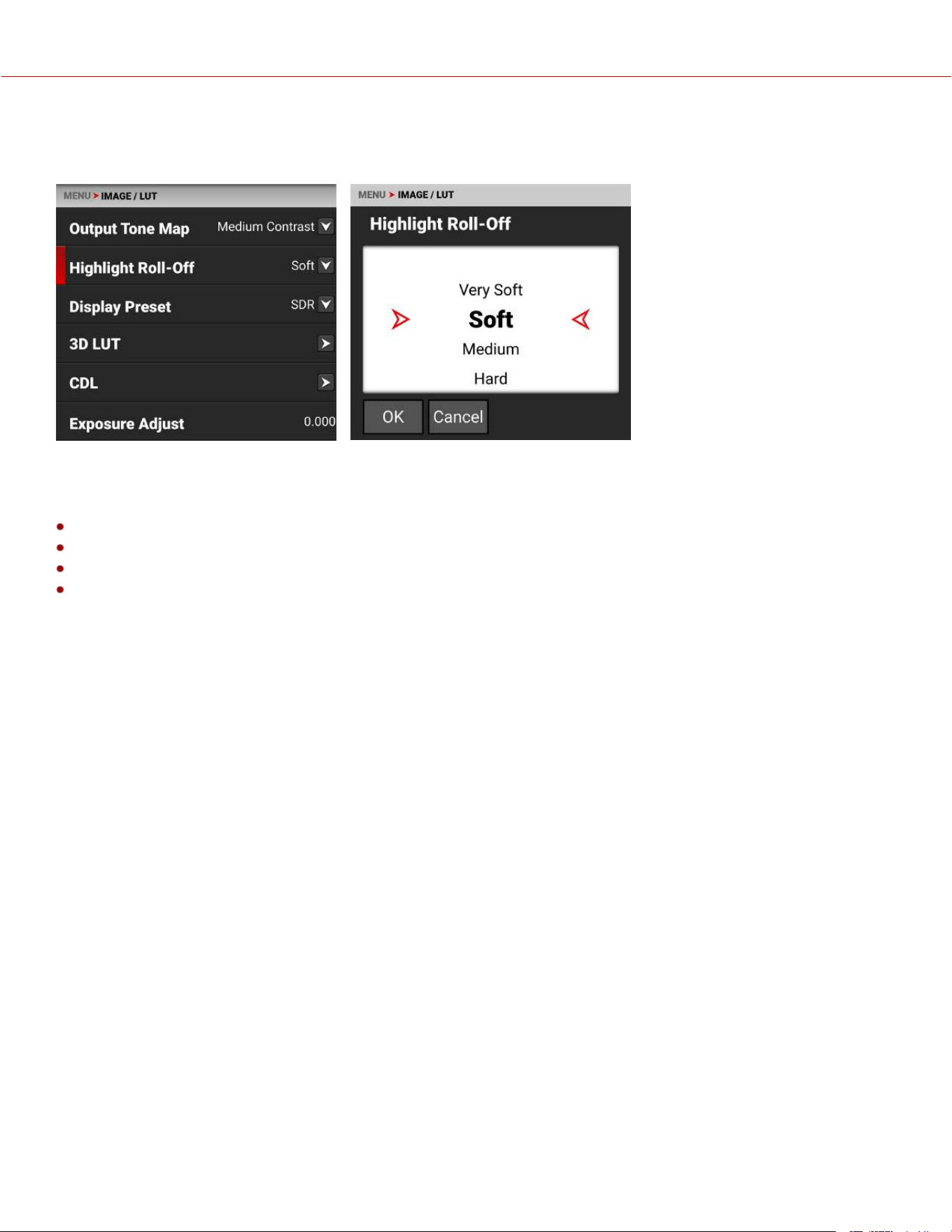
HIGHLIGHT ROLL-OFF
Use Highlight Roll-Off to select the desired highlight compression to use when displaying the camera output.
When shooting in R3D format, the camera stores this as metadata, which you can adjust non-destructively in post-
production after filming.
The Highlight Roll-Off selections include:
Very Soft - The lightest compression is applied to the image highlights
Soft - Soft compression is applied to the image highlights (default)
Medium - Medium compression is applied to the image highlights
Hard - The highest compression is applied to the image highlights.
COPYRIGHT © 2023 RED.COM, LLC 955-0218, REV A | 47
KOMODO-X
®
OPERATION GUIDE
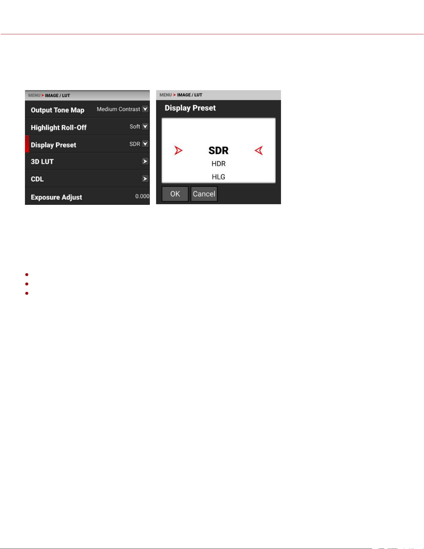
DISPLAY PRESET
Use Display Preset to select the gamma of the displayed preview image for the SDI port:
When shooting in R3D format, the camera stores this as metadata, which you can adjust non-destructively in post-
production after filming.
The Display Preset allows you to select the gamma for the camera preview and monitor output.
Each monitor is designed to display using a specific gamma. Most monitors use SDR. However, some support HDR and
HLG gamma signals. Select the display preset that works best with your monitor.
The selections are:
SDR - Standard Dynamic Range (default)
HDR - High Dynamic Range
HLG - Hybrid Log-Gamma
Standard-dynamic-range (SDR) video describes images or video using a conventional gamma curve signal.
High-dynamic-range (HDR) video images are recorded using the SMPTE-2084 PQ curve. This technology captures and
outputs a greater range of luminance than images recorded using standard-dynamic-range (SDR) methods.
Hybrid log-gamma (HLG) delivers HDR resolution without the need for metadata. This allows HLG to display well on
SDR and HDR monitors.
COPYRIGHT © 2023 RED.COM, LLC 955-0218, REV A | 48
KOMODO-X
®
OPERATION GUIDE
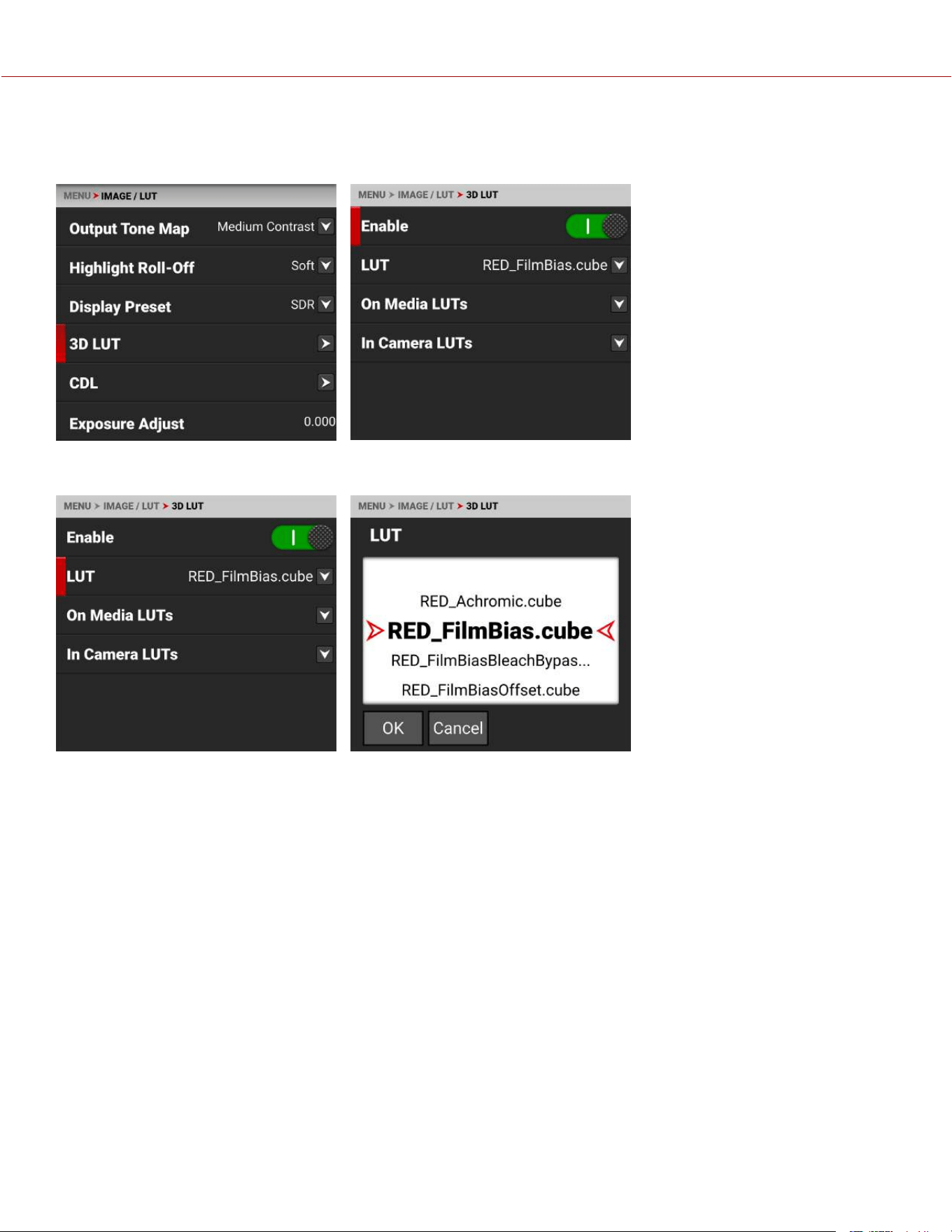
3D LUT
Use the 3D LUT menu to apply and manage the camera's Look-Up Tables (LUTs).
LUT
When you are recording in the ProRes format, you can choose to irreversibly encode (bake) the 3D LUT into the
recorded file. For more information, refer to the ProRes Color Profile section.
When you are recording in the R3D format, this LUT will be saved along with each clip on which it is activated during
recording. The output file name format for the LUT is clip_LUT Name.cube.
The LUT is non-destructive, and it is reversible, when recording in the R3D format.
To apply a 3D LUT, follow the instructions below:
1. Go to MENU > IMAGE / LUT > 3D LUT > LUT.
2. Select a LUT from the LUT list.
COPYRIGHT © 2023 RED.COM, LLC 955-0218, REV A | 49
KOMODO-X
®
OPERATION GUIDE
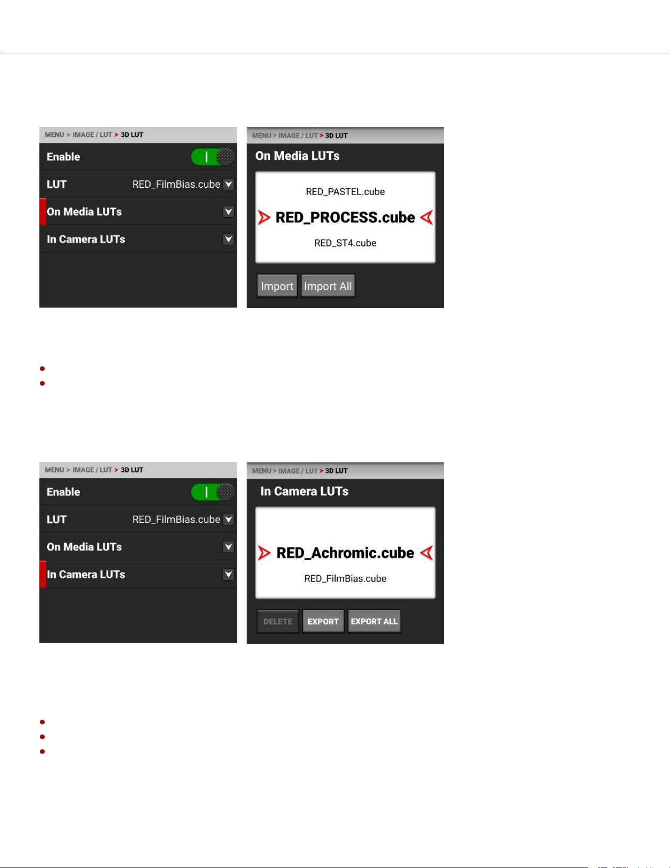
ON MEDIA LUTS
To import 3D LUTs from media, go to MENU > IMAGE / LUT > 3D LUT > On Media LUTs.
3D LUTs can be imported from media to the camera. When importing 3D LUTs from media to the camera, the 3D LUTs
must be saved on the root path of your media, in a folder titled "luts." The camera only supports 33x33x33 LUTs.
From On Media LUTs, you can:
Import the selected 3D LUT from the media to the camera
Import all 3D LUTs from the media to the camera.
When you copy LUTs from a computer to the media, make sure that the card reader is not set to read only.
IN CAMERA LUTS
To export and delete 3D LUTs stored in the camera, go to MENU > IMAGE / LUT > 3D LUT > In Camera LUTs.
You can export 3D LUTs stored on the camera, to media, to use on other cameras. When you export 3D LUTs from the
camera to media, the 3D LUTs are saved to a folder on the media called “luts.”
NOTE: When a LUT is active during record, the camera will automatically save the LUT along with the recorded clip.
From In Camera LUTs you can:
Delete a selected 3D LUT from the camera
Export a selected 3D LUT from the camera to the media
Export all 3D LUTs from the camera to the media.
COPYRIGHT © 2023 RED.COM, LLC 955-0218, REV A | 50
KOMODO-X
®
OPERATION GUIDE
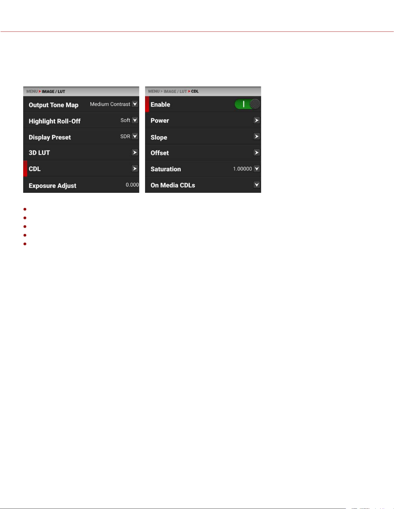
CDL
The Color Decision List (CDL) allows you to define the look of the camera's colors in your project.
NOTE: The CDL menu is disabled on Monochrome cameras.
Use the CDL menu to:
Enable the CDLs
Configure CDL Power
Configure CDL Slope
Configure CDL Offset
Configure CDL Saturation
MANAGE CDLS
Use the CDLs menu to import and export CDLs.
CDLs can be stored on the camera or transferred to media to be shared with other cameras. When exporting CDLs from
camera to media, the CDLs are saved to a folder on the media called “cdls”. When importing CDLs from media to the
camera, the CDLs must be stored on the media in a folder called “cdls.”
When you record with a CDL in ProRes format, the CDL is baked-in with the ProRes file. When you record with a CDL in
R3D format, the camera automatically saves the CDL file along with the R3D files.
To export selected CDLs from the camera to the media, refer to the In Camera CDLs section.
To import selected CDLs from the media to the camera, refer to the On Media CDL section.
CDL OVERVIEW
A Color Decision List (CDL) is a metadata file format developed by the American Society of Cinematographers (ASC) to
exchange standard color correction information between post production tools. This non-destructive color adjustment
layer simplifies the versioning of looks by updating simple metadata without the need to re-transfer the image data.
COPYRIGHT © 2023 RED.COM, LLC 955-0218, REV A | 51
KOMODO-X
®
OPERATION GUIDE

CDLs are very common in VFX workflows because the VFX artist needs both the ungraded shot and the intended look.
The ungraded shot allows the artist to comp in truly linear light, and the intended look is needed to confirm that the
individual plates still hold together after the grade is applied.
SLOPE, OFFSET AND POWER
The three CDL tone curve parameters are Slope, Offset and Power. These algorithms allow the camera to modify the
recorded image.
Slope multiplies the incoming data
Offset is sum of the incoming data
Power is a power function to the incoming data
These three relate to Gain, Lift, and Gamma in the following ways:
Slope = Gain
Gain Adjusts highlights.
Offset = Lift
Lift Increases the value of dark colors.
Power = Gamma
Gamma adjusts midtones.
These three relate to each other in the following ways:
Slope= input x slope
Offset= (input x slope) + offset
Power= ((input x slope) + offset) ^ power
The formula for ASC CDL color correction is:
where
is the color graded pixel code value
is the input pixel code value (0=black, 1=white)
is slope (any number 0 or greater, nominal value is 1.0)
is offset (any number, nominal value is 0)
is power (any number greater than 0, nominal value is 1.0)
The formula is applied to the three color values for each pixel using the corresponding slope, offset, and power
numbers for each color channel.
SATURATION
A fourth parameter “Saturation” is achieved by converting the out data in a Luma and Chroma component. The Chroma
Signal is then multiplied by the “Saturation” parameter.
FILM GRADE AND VIDEO GRADE
With Slope and Offset you can produce both a Film Grade “Exposure” and “Contrast” and a Video Grade “Lift” and
“Gain.”
Exposure is achieved by Offset
Contrast is achieved by a combination of Offset and Slope
Gain is achieved by Slope
Lift is achieved by a combination of Offset and Slope
Gamma is achieved by Power
COPYRIGHT © 2023 RED.COM, LLC 955-0218, REV A | 52
KOMODO-X
®
OPERATION GUIDE
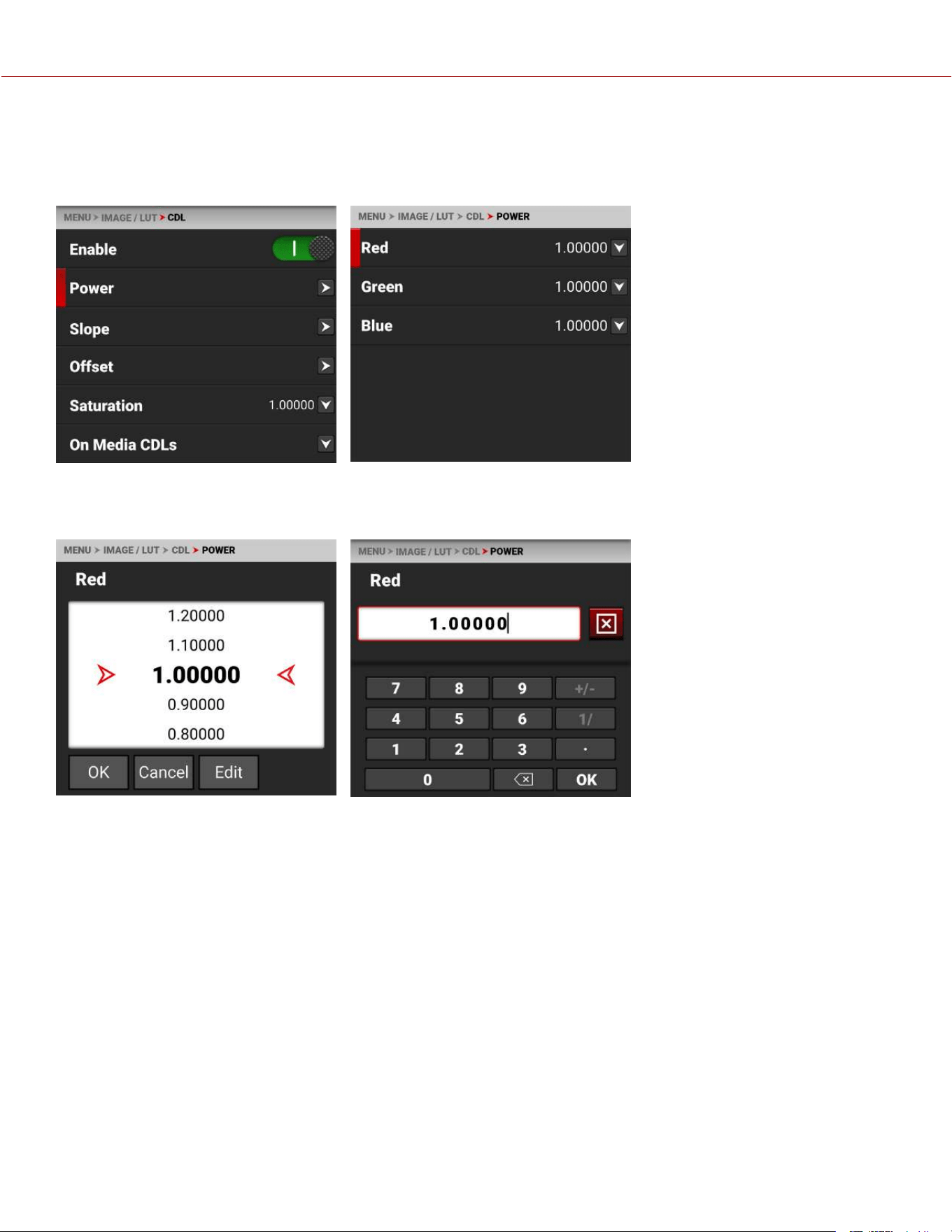
CDL POWER
The CDL Power settings control the power of the Red, Green, and Blue, color data.
NOTE: The CDL options are disabled on Monochrome cameras.
Use the CDL Power menu to adjust the power of the Red, Green, and Blue CDL data.
CDL POWER SETTINGS
The CDL Power settings range from 0.00000 to 4.00000. The default CDL Power setting for each color is 1.00000. The
Edit button opens the keypad where you can enter a specific CDL Power value.
COPYRIGHT © 2023 RED.COM, LLC 955-0218, REV A | 53
KOMODO-X
®
OPERATION GUIDE
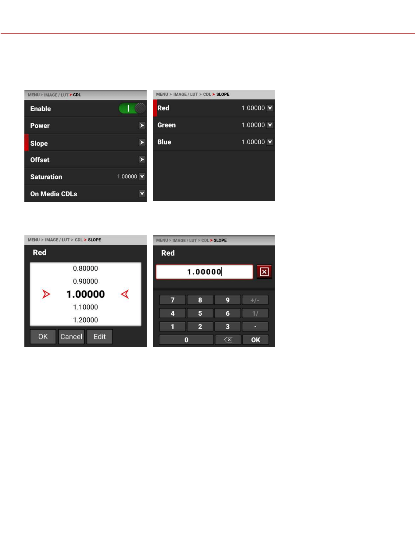
CDL SLOPE
The CDL Slope settings multiply the incoming RGB data.
NOTE: The CDL options are disabled on Monochrome cameras.
Use the CDL Slope menu to set the slope of the Red, Green, and Blue signals.
SLOPE SETTINGS
The CDL Slope settings range from 0.00000 to 2.00000. The default CDL Slope settings are 1.00000. The Edit button
opens a keypad where you can enter a specific CDL Slope value.
COPYRIGHT © 2023 RED.COM, LLC 955-0218, REV A | 54
KOMODO-X
®
OPERATION GUIDE
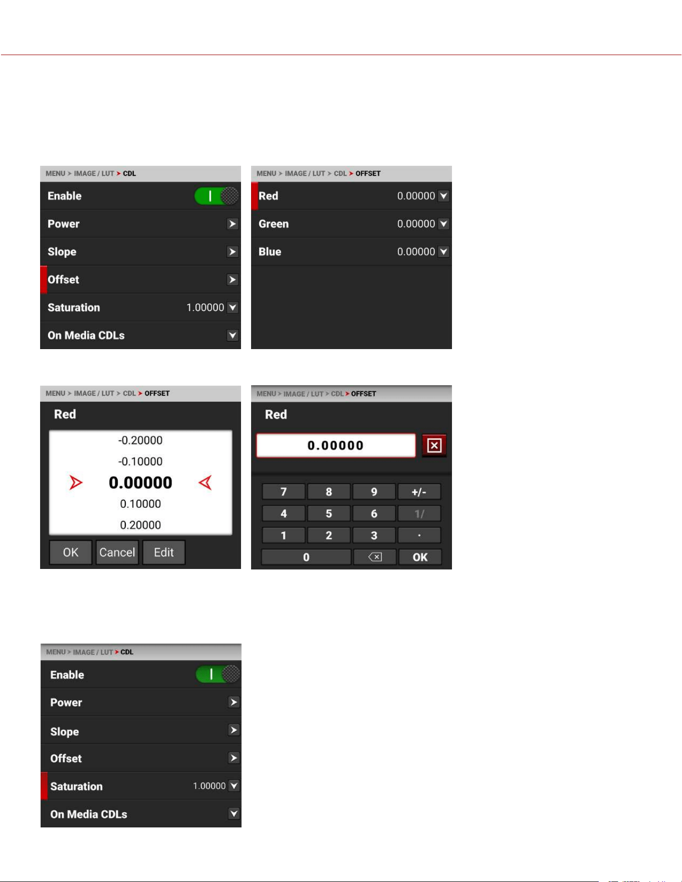
CDL OFFSET
The CDL Offset settings control the offset of the RGB color data.
NOTE: The CDL options are disabled on Monochrome cameras.
The Camera LCD Menu for CDL Offset:
Use the CDL Offset menu to adjust
the offset of the CDL Slope for the
Red, Green, and Blue CDL data.
RED GREEN AND BLUE OFFSETS
These CDL Offset settings range from -1.00000 to 1.00000. The default CDL Offset setting for each is 0.00000. The Edit
button opens the keypad, where you can enter a specific CDL Offset value.
CDL SATURATION
The CDL Saturation settings control the intensity of the color data.
COPYRIGHT © 2023 RED.COM, LLC 955-0218, REV A | 55
KOMODO-X
®
OPERATION GUIDE
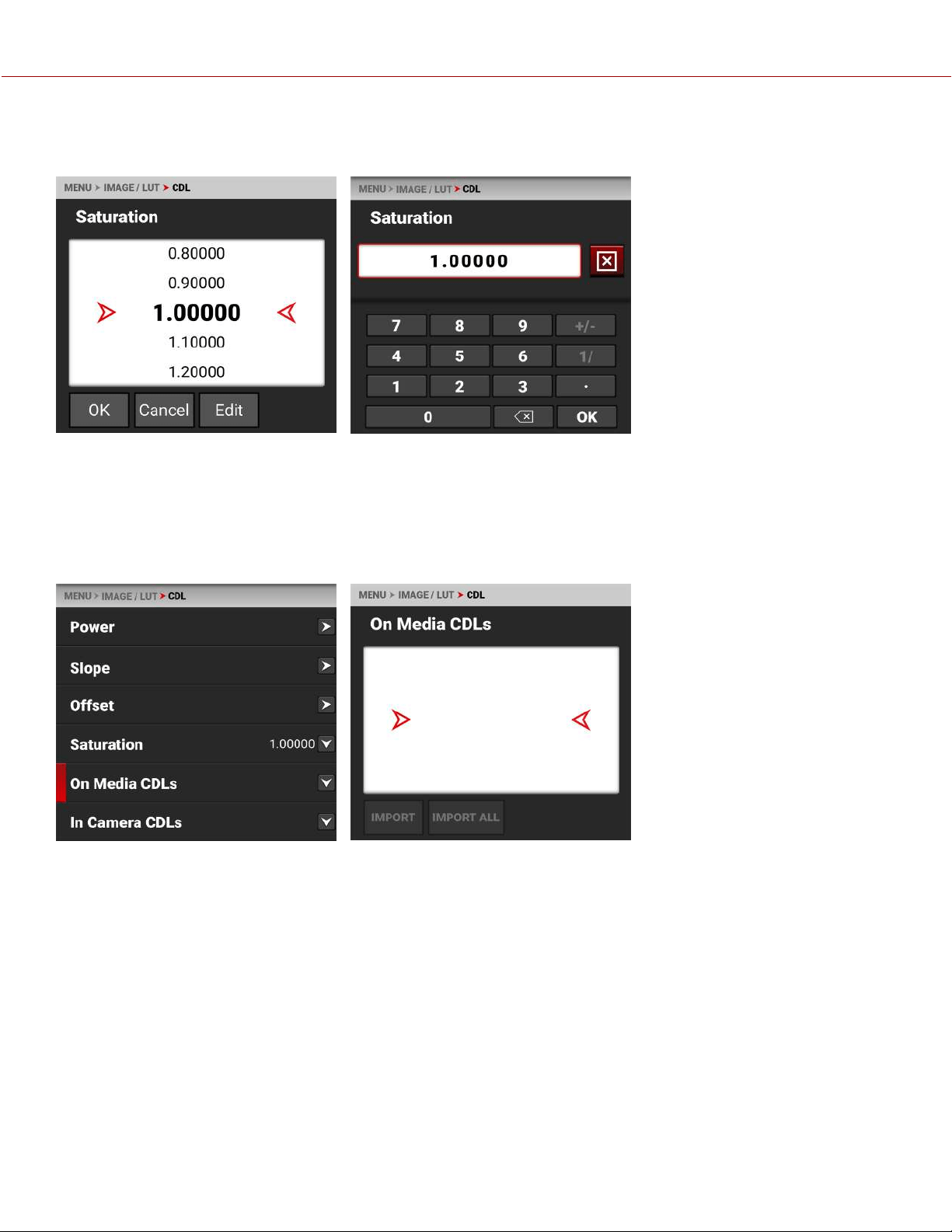
NOTE: The CDL options are disabled on Monochrome cameras.
Use the CDL Saturation menu to adjust the intensity of the image color.
The CDL Saturation settings range from 0.00000 to 4.00000. The default CDL Saturation setting is 1.00000. The Edit
button opens a keypad where you can enter a specific CDL Saturation value.
ON MEDIA CDL
Use On Media CDLs to import CDLs from the media to the camera.
NOTE: The CDL options are disabled on Monochrome cameras.
When importing CDLs from media
to the camera, the CDLs are saved
to a folder on the camera called
“cdls”.
From On Media CDLs you can
import a selected CDL from the
media to the camera, or you can
import all of the CDLs from the
media to the camera.
When you copy CDLs from a
computer to the media, make sure
that the card reader is not set to
Read Only.
COPYRIGHT © 2023 RED.COM, LLC 955-0218, REV A | 56
KOMODO-X
®
OPERATION GUIDE
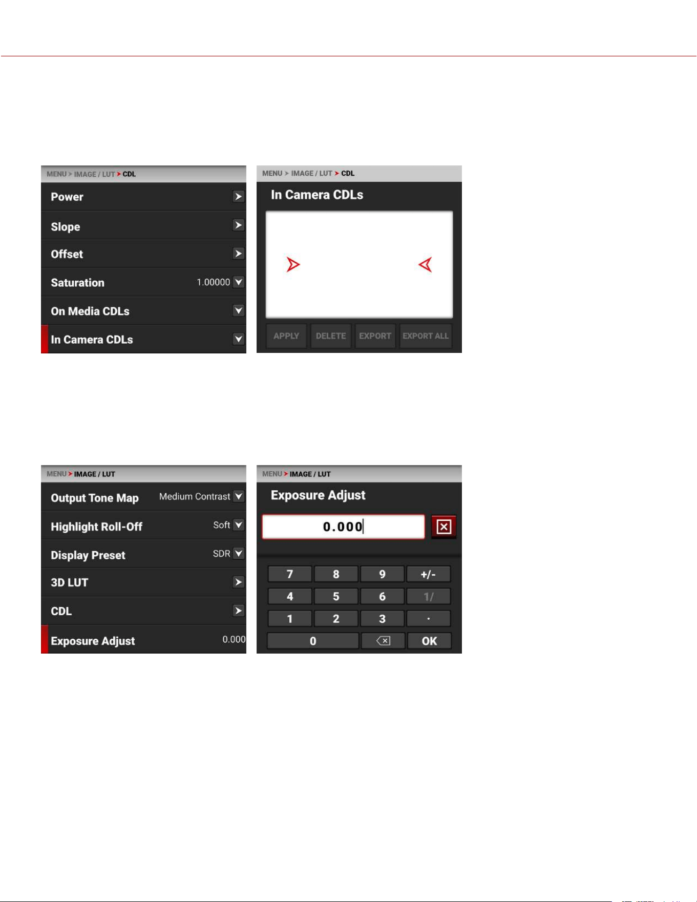
IN CAMERA CDLS
Use In Camera CDLs to export CDLs from the camera to the media. You can also select which stored CDL you want to
apply to the camera.
NOTE: The CDL options are disabled on Monochrome cameras.
When exporting CDLs from the camera to the media, the CDLs are saved to a folder on the media called “cdls.”
From In Camera CDLs, you can apply the selected CDL to the camera, delete the selected CDL from the camera, export
the selected CDL from the camera to the media, or export all of the CDLs from the camera to the media.
EXPOSURE ADJUST
Use Exposure Adjust to manually fine-tune the midtone exposure level.
The Exposure Adjust range is –8.000 to 8.000. The default is 0.000.
Exposure Adjust allows you to adjust the midtone exposure levels while preserving the highlights and shadows, even
when changed substantially. The Exposure Adjust setting is expressed in terms of relative exposure value (EV), where
each unit represents a 1-stop change in midtone exposure level.
COPYRIGHT © 2023 RED.COM, LLC 955-0218, REV A | 57
KOMODO-X
®
OPERATION GUIDE
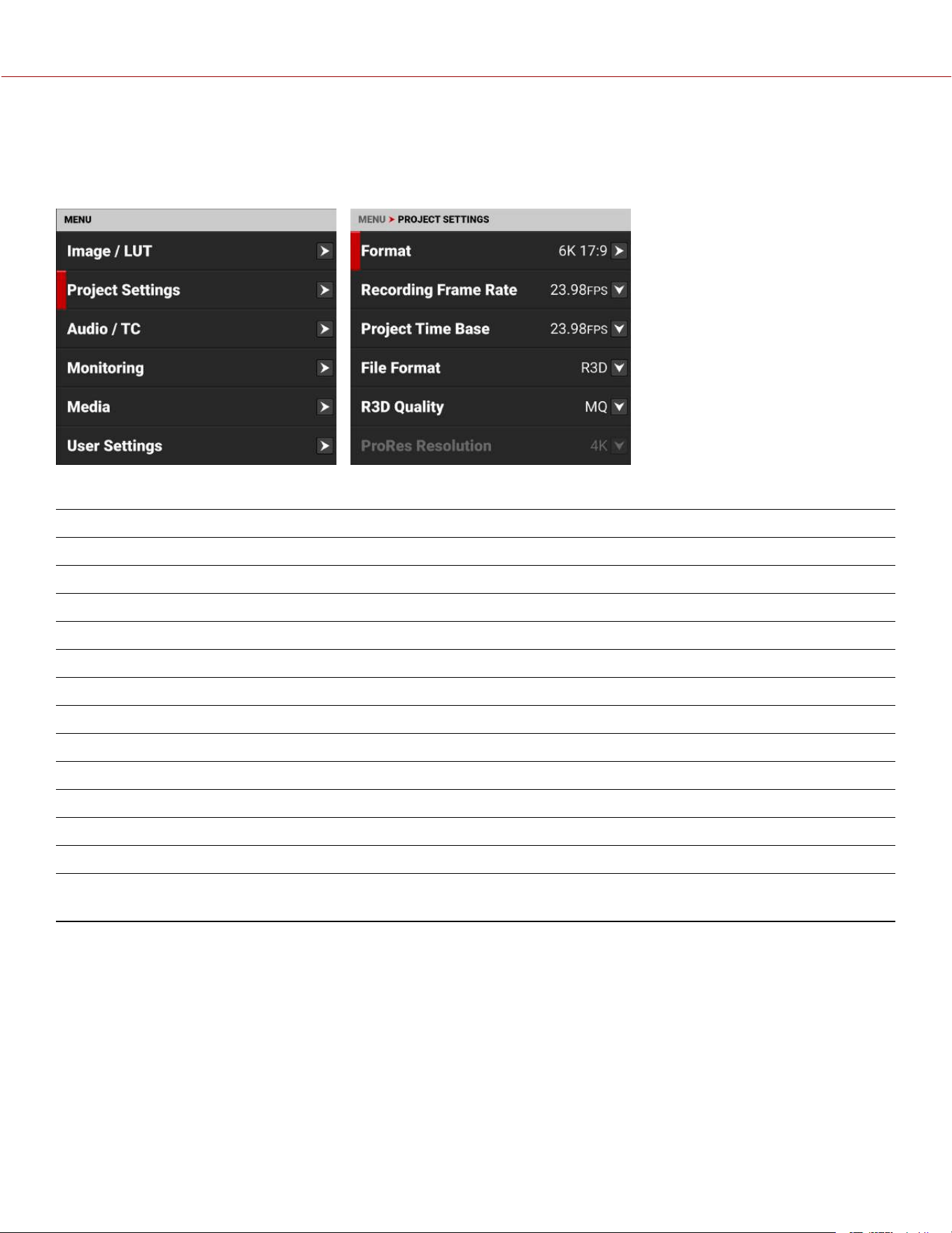
PROJECT SETTINGS MENU
The Project Settings menu contains the camera's main recording configuration settings.
From the Onboard LCD touchscreen menu, tap Project Settings:
Use the Project Settings menu to configure the recording settings:
ITEMS DETAILS
Format Size of the area captured by the sensor
Recording Frame Rate Frames recorded per second
Project Time Base Image playback rate
File Format R3D or ProRes file formats
R3D Quality Compression level of the recorded image file
ProRes Resolution Resolution of the recorded ProRes image file
ProRes Codec ProRes codec selection
ProRes Color Profile RWG / Log3G10 or Image / LUT settings
Pre-Record Enable and configure a pre-record clip
Recording Mode Select Motion or Timelapse mode
Timelapse Interval Time and Frames per Interval
Frame Limit Enable, Frames, and Playback Duration
Slate Enter the Camera ID, Camera Position, Camera Operator, Scene,
Shot, Take, Production, Director, DoP, and Unit
COPYRIGHT © 2023 RED.COM, LLC 955-0218, REV A | 58
KOMODO-X
®
OPERATION GUIDE
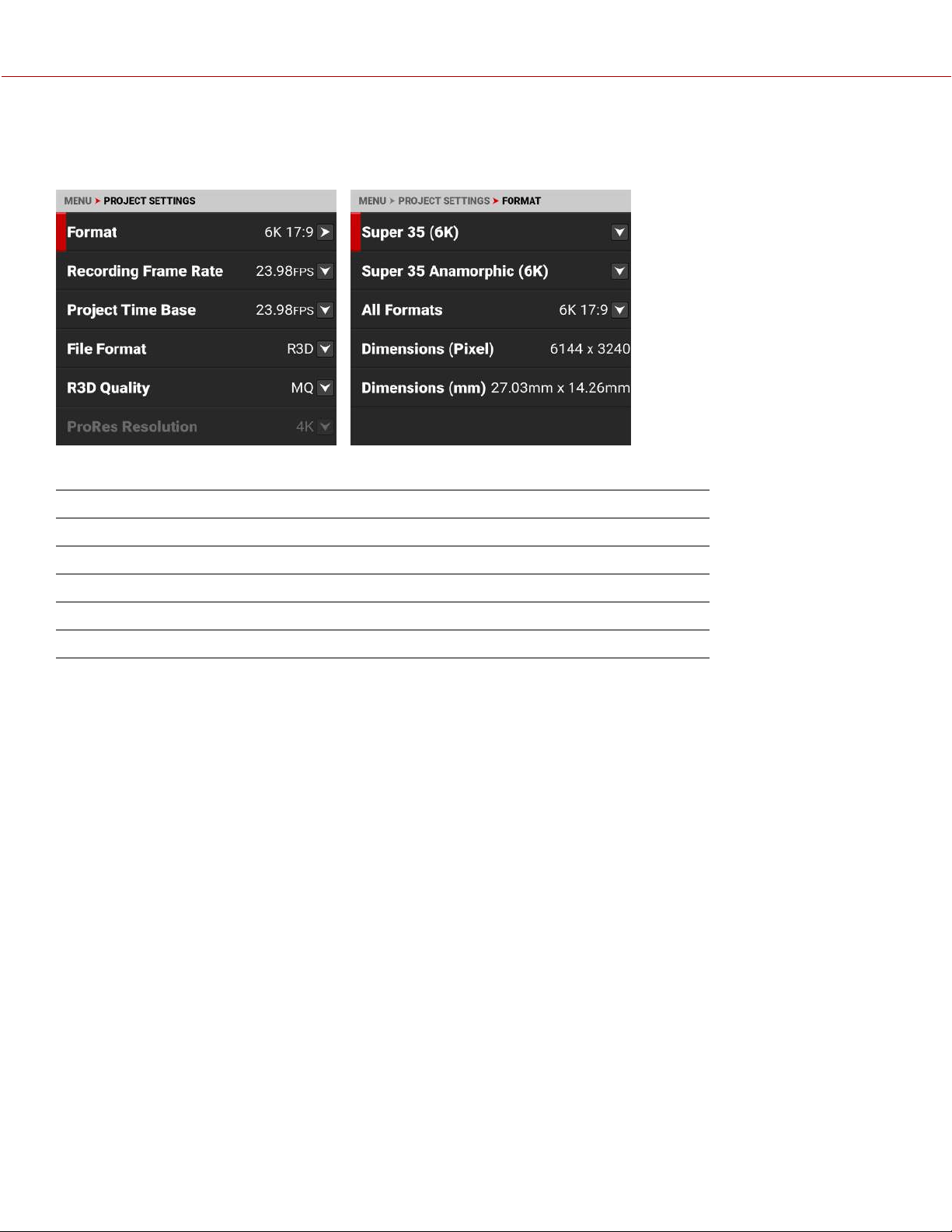
FORMAT
Use the Format setting to designate how much of the sensor the camera should use to capture images.
Use the Format menu to configure the camera's sensor capture area settings:
ITEMS DETAILS
Super 35 (6K) Select from Super 35 sensor capture areas
Super 35 Anamorphic (6K) Select from Super 35 anamorphic sensor capture areas
All Formats Select from all sensor capture areas
Dimensions (Pixel) Displays the dimensions of the selected format in pixels
Dimensions (mm) Displays the dimensions of the selected format in millimeters
The available aspect ratios are determined by the selected resolution. The default format setting is 6K 17:9.
When you lower the resolution in the Format menu, only a portion of the sensor is used. The camera does not
downscale from the 6K 17:9 format when recording RAW.
COPYRIGHT © 2023 RED.COM, LLC 955-0218, REV A | 59
KOMODO-X
®
OPERATION GUIDE
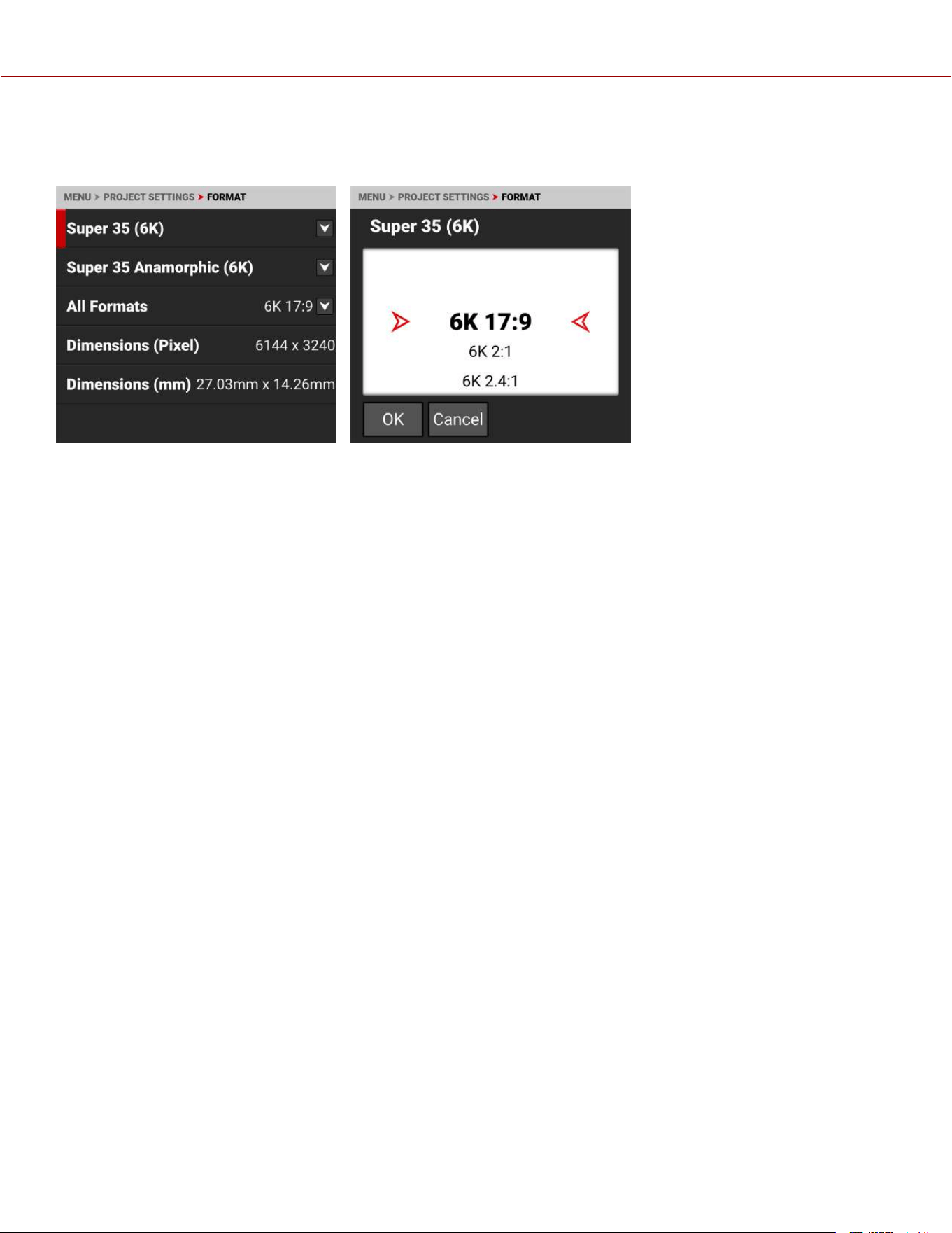
SUPER 35 (6K)
Use the Super 35 (6K) format setting to designate how much of the sensor the camera should use to capture images.
The available aspect ratios are determined by the selected resolution.
When you lower the resolution on the camera, only a portion of the sensor is used. The camera does not downscale
from the 6K 17:9 format when recording RAW.
SUPER 35 (6K) FORMAT SPECIFICATIONS
This table contains the dimensions of the sensor area in Pixels and in Millimeters used by each Super 35 (6K) format.
The default format is 6K 17:9.
FORMAT DIMENSION (PIXELS) DIMENSIONS (MM)
Width Height Width Height Diagonal
6K 17:9
6144 3240 27.03 14.26 30.56
6K 2:1
6144 3072 27.03 13.52 30.22
6K 2.4:1
6144 2592 27.03 11.40 29.34
6K 16:9
5760 3240 25.34 14.26 29.08
6K 1:1
3240 3240 14.26 14.26 20.17
COPYRIGHT © 2023 RED.COM, LLC 955-0218, REV A | 60
KOMODO-X
®
OPERATION GUIDE
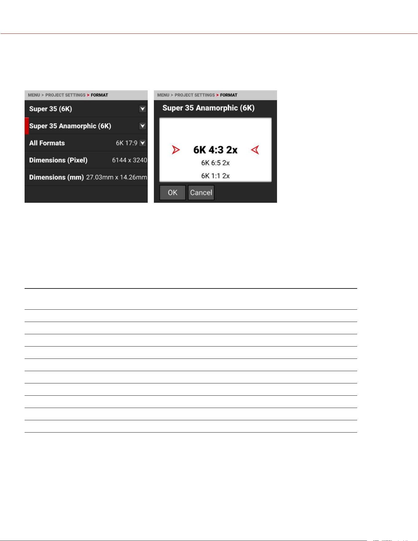
SUPER 35 ANAMORPHIC (6K)
Use the Super 35 Anamorphic Format setting to designate how much of the sensor the camera should use to capture
images.
The available aspect ratios are determined by the selected resolution.
When you lower the resolution on the camera, only a portion of the sensor is used. The camera does not downscale
from the 6K 17:9 format when recording RAW.
SUPER 35 ANAMORPHIC (6K) FORMAT SPECIFICATIONS
This table contains the effective dimensions of the sensor area in Pixels and in Millimeters used by each Super 35
Anamorphic (6K) format.
The default setting is 6K 4:3 2x.
FORMAT DIMENSION (PIXELS) DIMENSION DE-SQUEEZED
(PIXELS)
DIMENSIONS (MM)
WIDTH HEIGHT WIDTH HEIGHT WIDTH HEIGHT DIAGONAL
6K 4:3 2x
4320 3240 8640 3240 19.01 14.26 23.76
6K 6:5 2x
3888 3240 7776 3240 17.11 14.26 22.27
6K 1:1 2x
3240 3240 6480 3240 14.26 14.26 20.17
6K 3:2 1.8x
4860 3240 8748 3240 21.38 14.26 25.70
6K 4:3 1.8x
4320 3240 7776 3240 19.01 14.26 23.76
6K 3:2 1.6x
4860 3240 7776 3240 21.38 14.26 25.70
6K 16:9 1.5x
5760 3240 8640 3240 25.34 14.26 29.08
6K 17:9 1.3x
6144 3240 8192 3240 27.03 14.26 30.56
6K 17:9 1.25x
6144 3240 7680 3240 27.03 14.26 30.56
COPYRIGHT © 2023 RED.COM, LLC 955-0218, REV A | 61
KOMODO-X
®
OPERATION GUIDE
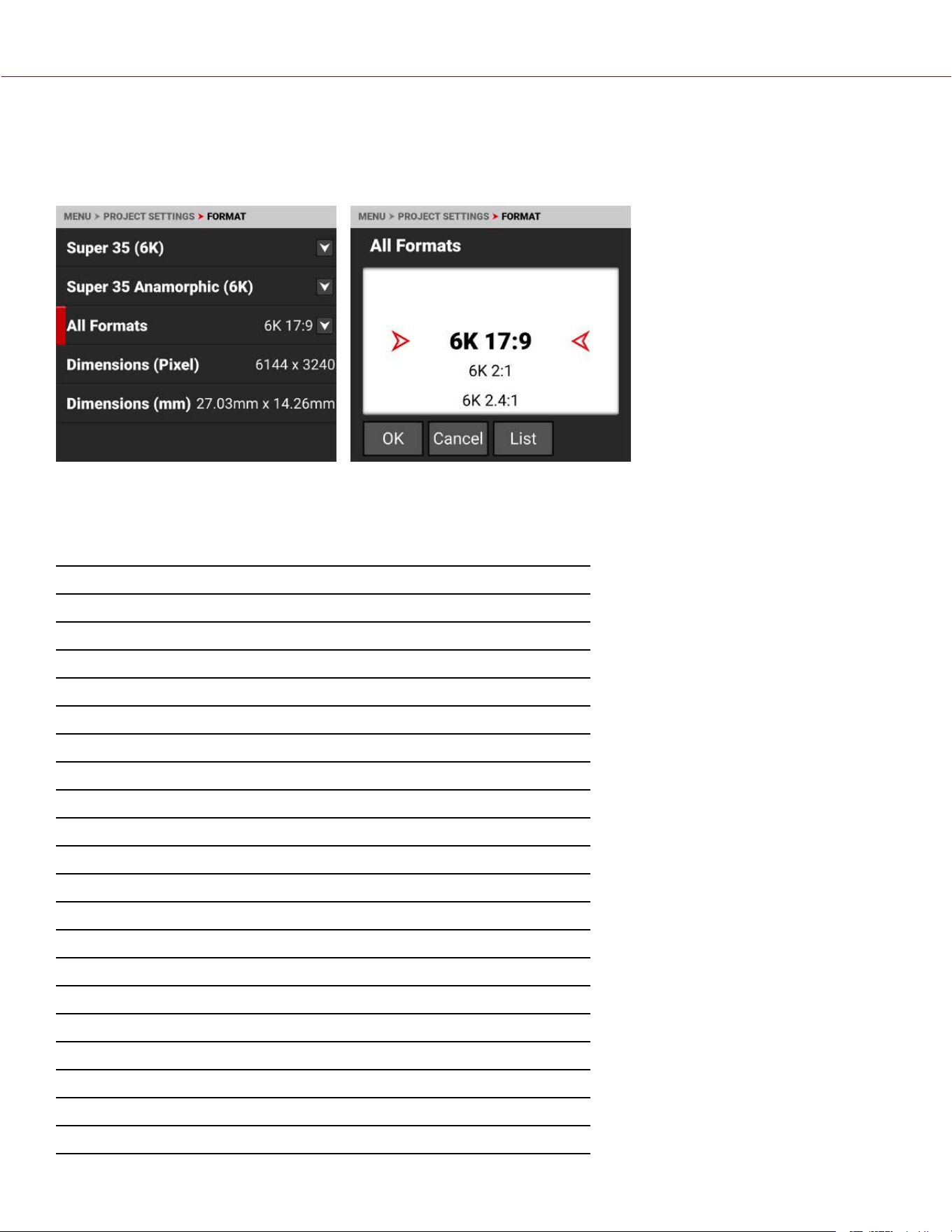
ALL FORMATS
Use the All Formats setting to select from all of the possible formats to designate how much of the sensor the camera
should use to capture images.
The available aspect ratios are
determined by the selected
resolution.
When you lower the resolution on
the camera, only a portion of the
sensor is used. The camera does
not downscale from the 6K 17:9
format when recording RAW.
FORMAT SPECIFICATIONS
This table contains the dimensions of the sensor area in Pixels and in Millimeters used by all of the camera formats. The
default setting is 6K 17:9.
FORMAT DIMENSION (PIXELS) DIMENSIONS (MM)
WIDTH HEIGHT WIDTH HEIGHT DIAGONAL
6K 17:9
6144 3240 27.03 14.26 30.56
6K 2:1
6144 3072 27.03 13.52 30.22
6K 2.4:1
6144 2592 27.03 11.40 29.34
6K 16:9
5760 3240 25.34 14.26 29.08
6K 1:1
3240 3240 14.26 14.26 20.17
6K 4:3 2x
4320 3240 19.01 14.26 23.76
6K 6:5 2x
3888 3240 17.11 14.26 22.27
6K 1:1 2x
3240 3240 14.26 14.26 20.17
6K 3:2 1.8x
4860 3240 21.38 14.26 25.70
6K 4:3 1.8x
4320 3240 19.01 14.26 23.76
6K 3:2 1.6x
4860 3240 21.38 14.26 25.70
6K 16:9 1.5x
5760 3240 25.34 14.26 29.08
6K 17:9 1.3x
6144 3240 27.03 14.26 30.56
6K 17:9 1.25x
6144 3240 27.03 14.26 30.56
5K 17:9
5120 2700 22.53 11.88 25.47
5K 16:9
4800 2700 21.12 11.88 24.23
4K 17:9
4096 2160 18.02 9.50 20.37
4K 16:9
3840 2160 16.90 9.50 19.39
2K 17:9
2048 1080 9.01 4.75 10.19
COPYRIGHT © 2023 RED.COM, LLC 955-0218, REV A | 62
KOMODO-X
®
OPERATION GUIDE
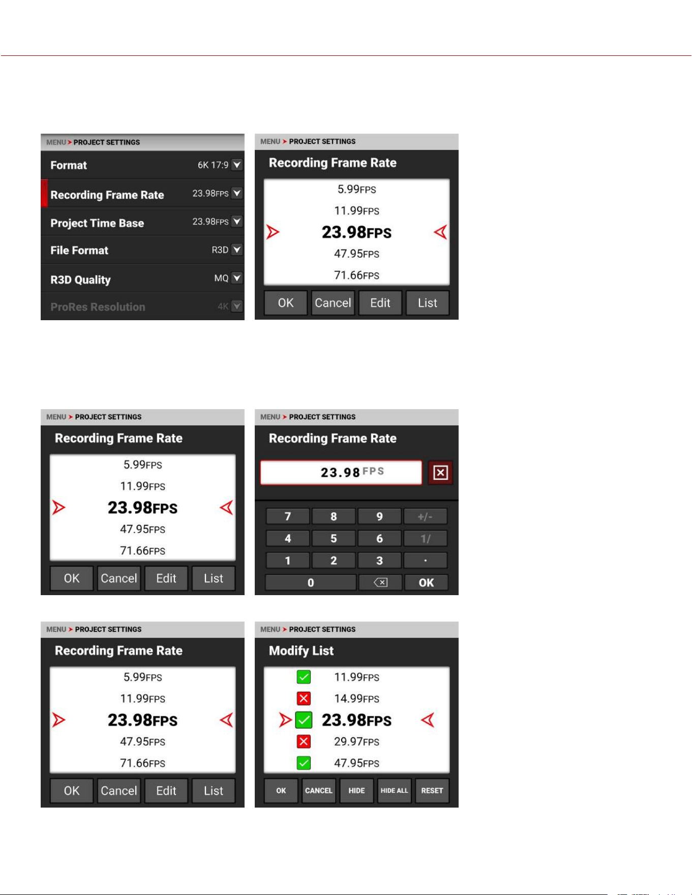
RECORDING FRAME RATE
Use Recording Frame Rate to select the recording frame rate (also referred to as the capture frame rate).
The recording frame rate is the number of frames per second (FPS) that are recorded. The recording frame rate is
different from the project time base, which is the rate at which the footage will be played back. Lower values than the
project time base will result in under-cranking (fast motion playback) and values larger than the project time base will
result in over-cranking (slow motion playback).
You can tap EDIT to change the Recording Frame Rate menu values manually.
You can tap LIST to choose which values you want to display on the menu list.
The maximum frame rate for each format is determined by Project Time Base and Format.
COPYRIGHT © 2023 RED.COM, LLC 955-0218, REV A | 63
KOMODO-X
®
OPERATION GUIDE
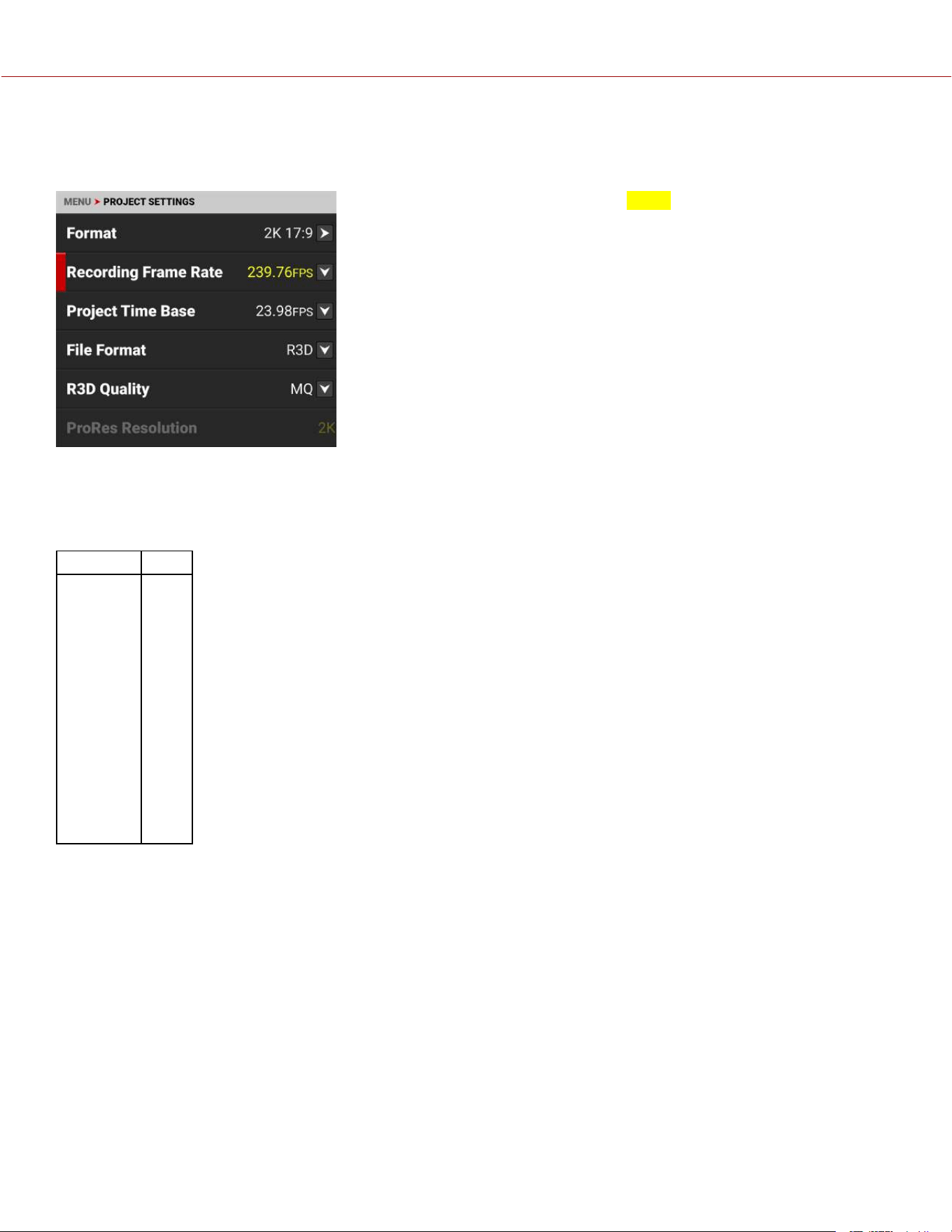
When you select a Project Time Base, the camera automatically selects a matching Recording Frame Rate and an R3D
Quality (when possible). You must change the Recording Frame Rate and R3D Quality after the Project Time Base to
select a different setting.
A Recording Frame Rate highlighted in yellow will result in playback occurring
at a different frame rate than the original recording, and will record varispeed
audio.
FORMATS AND FRAME RATES
This table lists the camera's maximum recording frame rates. These rates are based on a Project Time Base setting of
24 frames per second (24 FPS).
FORMAT FPS
6K 17:9
80
6K 2:1
84
6K 2.4:1
100
6K 16:9
80
6K 1:1
80
5K 17:9
96
5K 16:9
96
4K 17:9
120
4K 16:9
120
2K 17:9
240
COPYRIGHT © 2023 RED.COM, LLC 955-0218, REV A | 64
KOMODO-X
®
OPERATION GUIDE
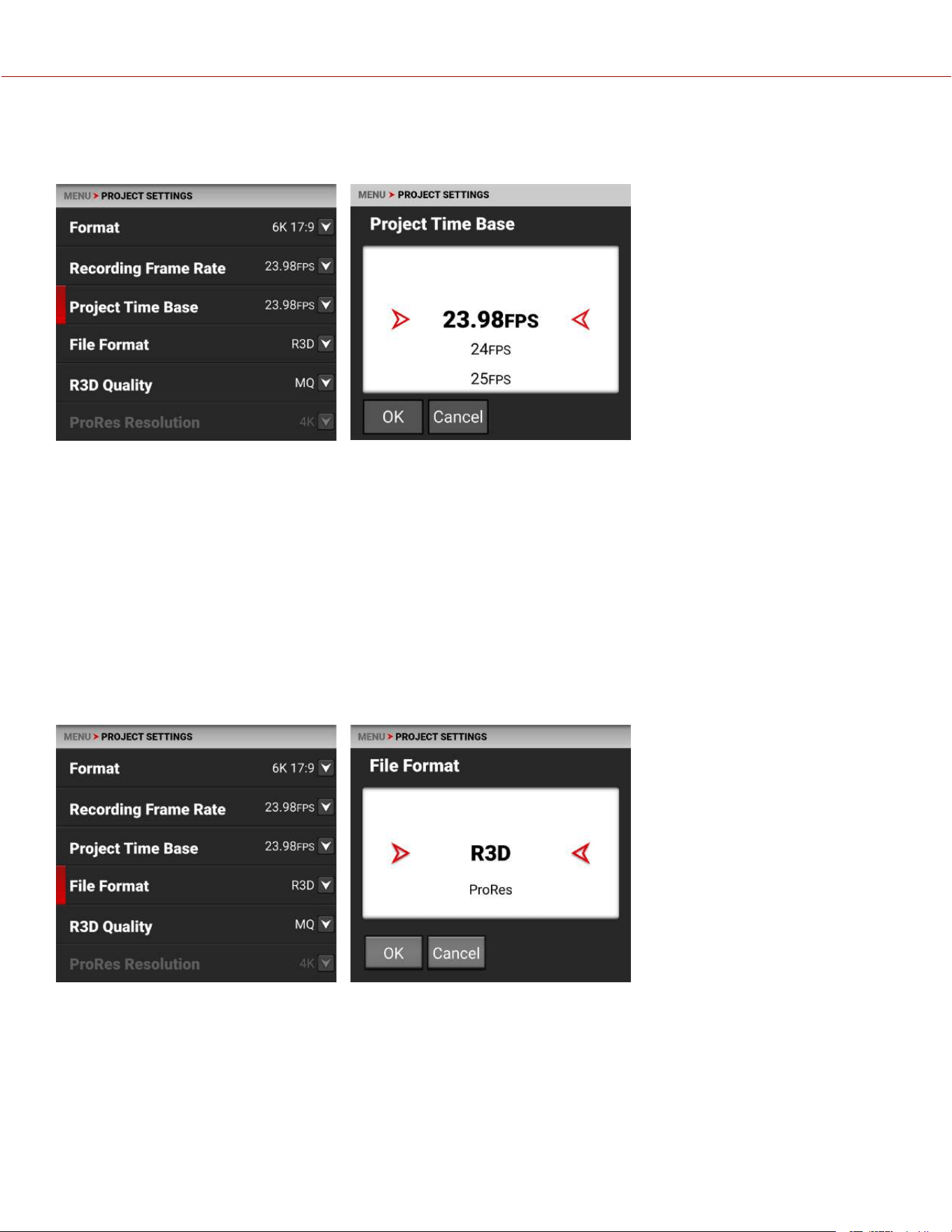
PROJECT TIME BASE
Use the Project Time Base setting to choose the playback rate for the recorded footage.
The following project time bases are available:
• 23.98 FPS (Default) • 25.00 FPS • 30.00 FPS • 59.94 FPS
• 24.00 FPS • 29.97 FPS • 50.00 FPS • 60.00 FPS
When you select the Project Time Base, it changes the Recording Frame Rate to the same setting (when possible).
When you change the Format, the Recording Frame Rate and Project Time Base do not automatically update. You must
select the Project Time Base after you change the Format setting.
NOTE: When the Recording Frame Rate is set to a higher speed than the Project Time Base setting, audio is recorded
as varispeed audio (refer to Audio / TC Menu).
FILE FORMAT
Use File Format to select the format that the camera uses to record image files.
COPYRIGHT © 2023 RED.COM, LLC 955-0218, REV A | 65
KOMODO-X
®
OPERATION GUIDE
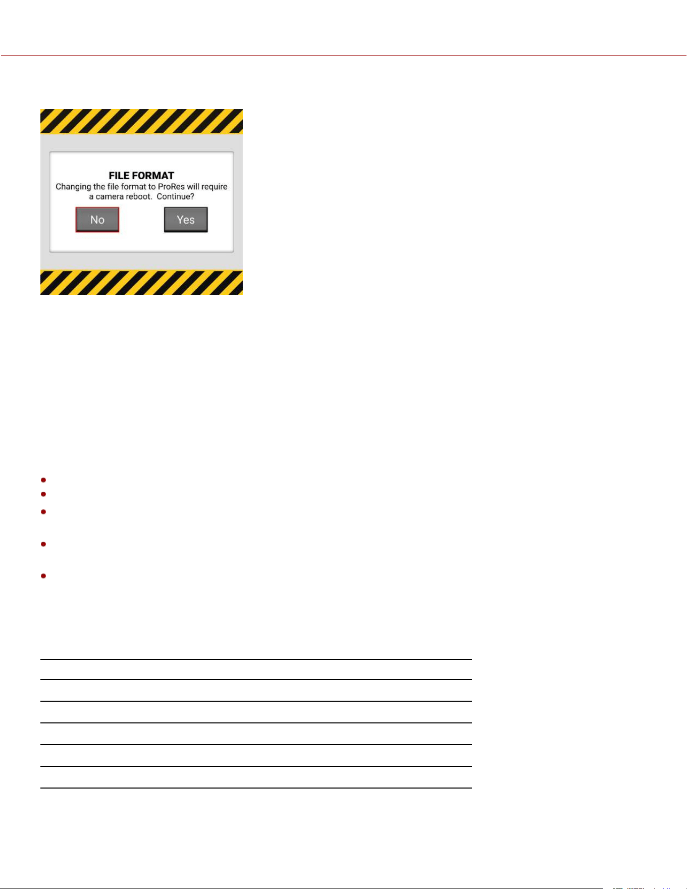
When you change the file format, a message warns you that the camera must be rebooted to complete the change:
R3D REDCODE FILE FORMAT
The RED R3D file format records images in a compressed RAW format. In comparison to Apple ProRes, REDCODE
RAW data does not bake in image settings like ISO, saturation, or LUTs, allowing more flexibility in post-processing
workflows without reducing image quality or dynamic range. Instead R3D files store the image settings as Metadata.
You can open and process R3D files with REDCINE-X PRO or with non-linear editing (NLE) software that supports the
RED SDK.
R3D is the camera's default file format.
APPLE PRORES FORMAT
This section provides general information about recording Apple ProRes files with the camera, including:
The maximum recording frame rate in ProRes is 120 frames per second (FPS).
QuickTime files have the same metadata as the REDCODE RAW files. The metadata is per clip, and not per frame.
You can select a Format from the Project Settings Menu and the camera will scale it to the target resolution you
select in ProRes Resolution.
Recording 4K ProRes files requires 4K and above formats in 17:9. When in ProRes, formats below 4K will
automatically be recorded as 2K or HD.
For more information about Apple ProRes, including the data rates for each codec, refer to the Apple ProRes White
Paper.
APPLE PRORES DESCRIPTION
The table below describes each supported Apple ProRes codec.
NAME CHROMA SAMPLING DATA RATE
ProRes 4444 XQ Y' C
b
C
r
+α 4:4:4:4 1697 Mbps at 4K 17:9 and 24 FPS
ProRes 4444 Y' C
b
C
r
+α 4:4:4:4 1131 Mbps at 4K 17:9 and 24 FPS
ProRes 422 HQ Y' C
b
C
r
4:2:2 754 Mbps at 4K 17:9 and 24 FPS
ProRes 422 Y' C
b
C
r
4:2:2 503 Mbps at 4K 17:9 and 24 FPS
ProRes 422 LT Y' C
b
C
r
4:2:2 350 Mbps at 4K 17:9 and 24 FPS
COPYRIGHT © 2023 RED.COM, LLC 955-0218, REV A | 66
KOMODO-X
®
OPERATION GUIDE
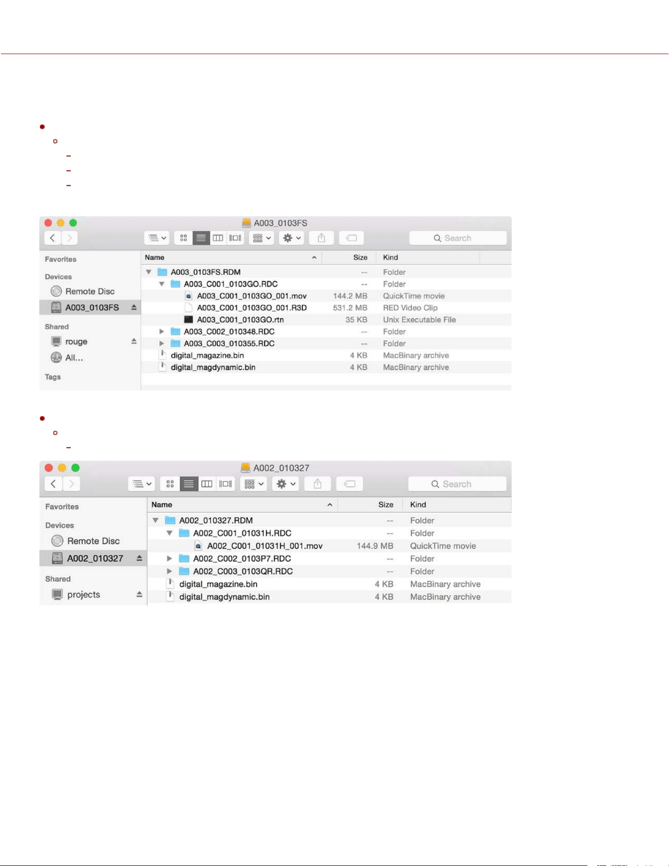
FILE STRUCTURE OF RECORDED APPLE PRORES FILES
When you record using R3D + ProRes Proxy, this is the file structure of the recorded files on the media:
.RDM Folder
.RDC Folder
.mov
.R3D
.rtn (RED Thumbnail file)
NOTE: The camera creates multiple .mov files, similar to how the camera creates multiple R3D files.
When you record using ProRes format, this is the file structure of the recorded files on the media:
.RDM Folder
.RDC Folder
.mov
COPYRIGHT © 2023 RED.COM, LLC 955-0218, REV A | 67
KOMODO-X
®
OPERATION GUIDE
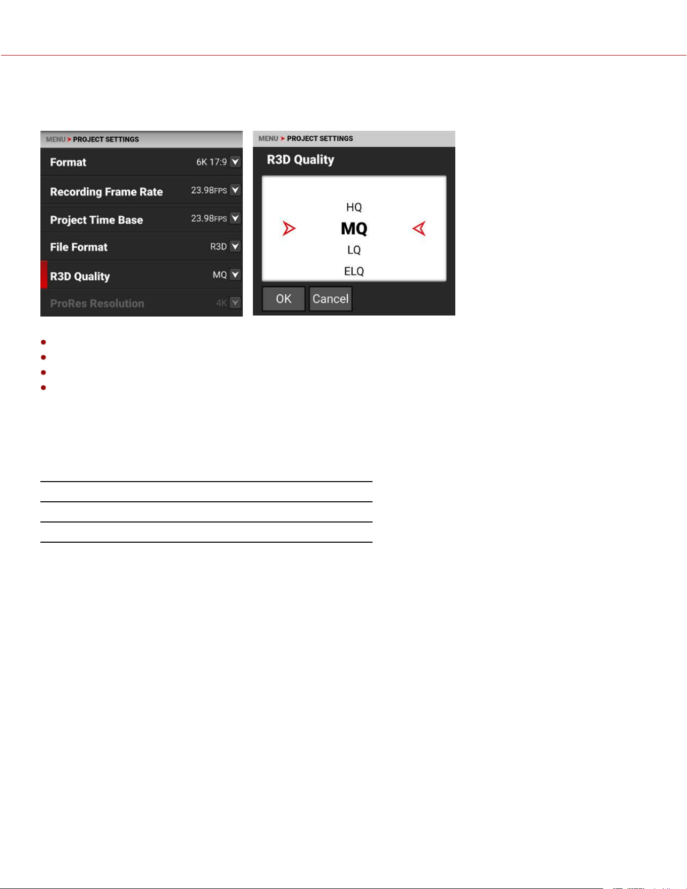
R3D QUALITY
Use R3D Quality to select the R3D data rate the camera uses to record the image files.
The R3D Quality selections include:
HQ - High data rate and less recording time
MQ - Medium data rate (default) and longer recording time
LQ - Low data rate and long recording time
ELQ - Lowest data rate and longest recording time
For high complexity scenes, VFX, and stills from motion workflows, RED recommends the HQ setting. For cinema (non-
VFX) and high-end TV, RED recommends the MQ setting. For TV, online content, documentary and interviews, RED
recommends the LQ setting. ELQ compression mode provides nearly 50% more recording time than LQ, and RED
recommends using ELQ for scenes where the complexity is low or the final delivery resolution is lower than the
acquisition resolution (downsampling).
R3D QUALITY DATA RATES
FORMAT 24P HQ 24P MQ 24P LQ 24P ELQ
6K 17:9 239 MB/s 168 MB/s 105 MB/s 65 MB/s
COPYRIGHT © 2023 RED.COM, LLC 955-0218, REV A | 68
KOMODO-X
®
OPERATION GUIDE
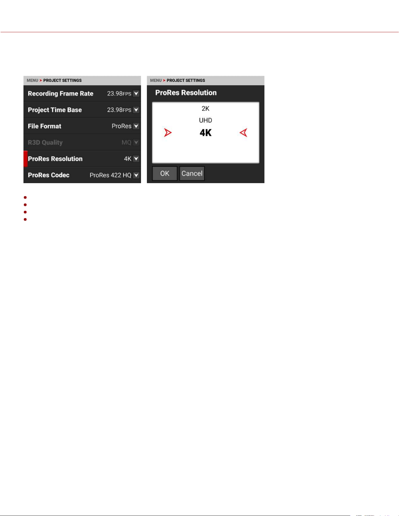
PRORES RESOLUTION
When you enable ProRes as the File Format you can select the ProRes resolution.
The ProRes Resolution selections include:
HD (16:9)
2K (17:9)
UHD (16:9)
4K (17:9, default).
The camera will downscale to achieve the selected ProRes resolution when the aspect ratios of your format and ProRes
resolution do not match. It is recommended to shoot 4K or 2K ProRes when the format is 17:9, and to shoot UHD or HD
when the format is 16:9.
COPYRIGHT © 2023 RED.COM, LLC 955-0218, REV A | 69
KOMODO-X
®
OPERATION GUIDE
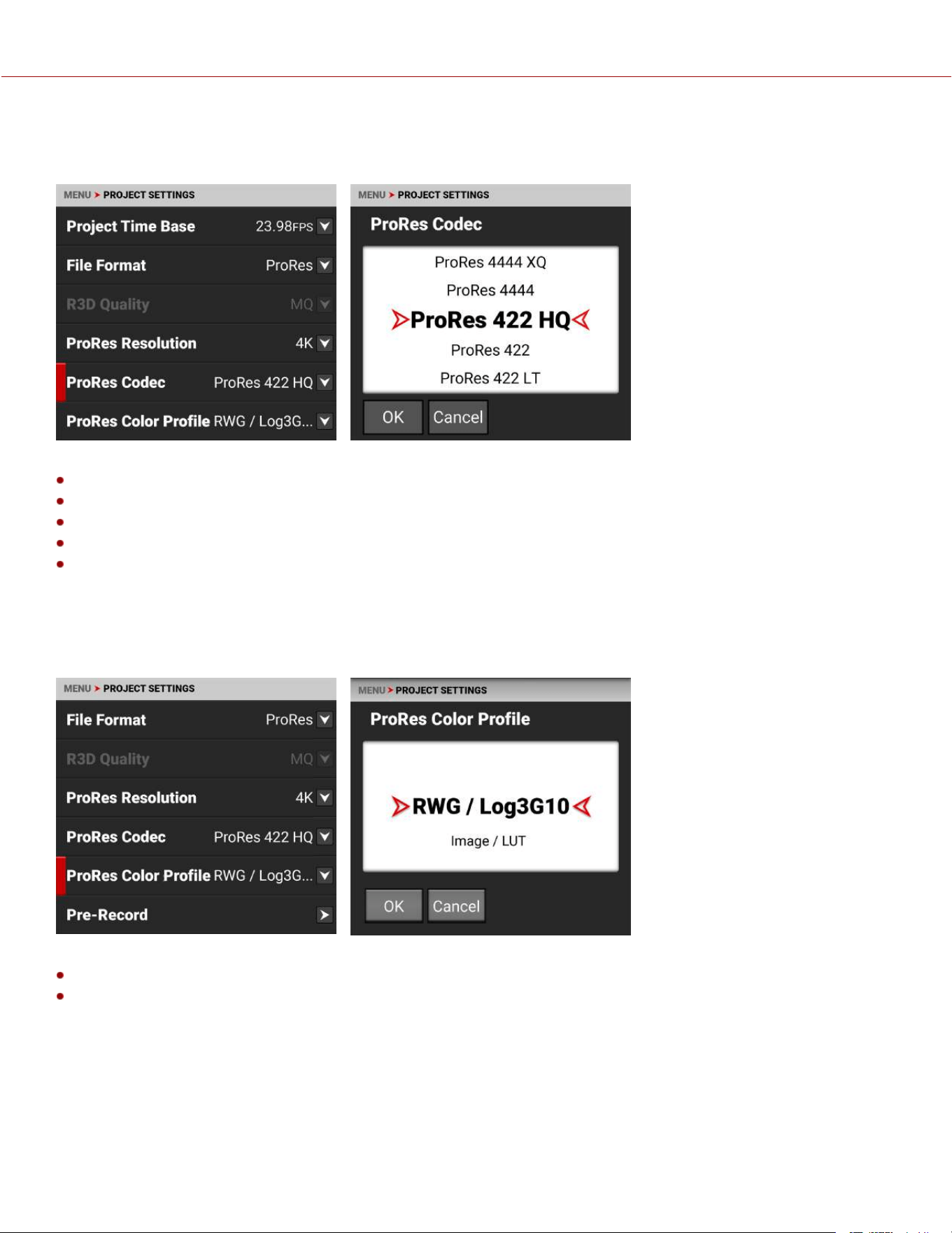
PRORES CODEC
When you enable ProRes as the File Format you can select the ProRes Codec.
The ProRes Codec selections include:
ProRes 4444 XQ
ProRes 4444
ProRes 422 HQ
ProRes 422
ProRes 422 LT
NOTE: Some ProRes codec selections are not available in all frame rates.
PRORES COLOR PROFILE
When you enable ProRes as the File Format you can select the color profile.
The ProRes Color Profile settings include:
RWG/Log3G10 - REDWideGamutRGB color space and Log3G10 gamma curve
Image / LUT - Applies all Image / LUT settings for Output Color Space, Display Preset, 3D LUT, and CDL.
NOTE: All ProRes Color Profile settings bake in both the ISO and the White Balance settings.
COPYRIGHT © 2023 RED.COM, LLC 955-0218, REV A | 70
KOMODO-X
®
OPERATION GUIDE
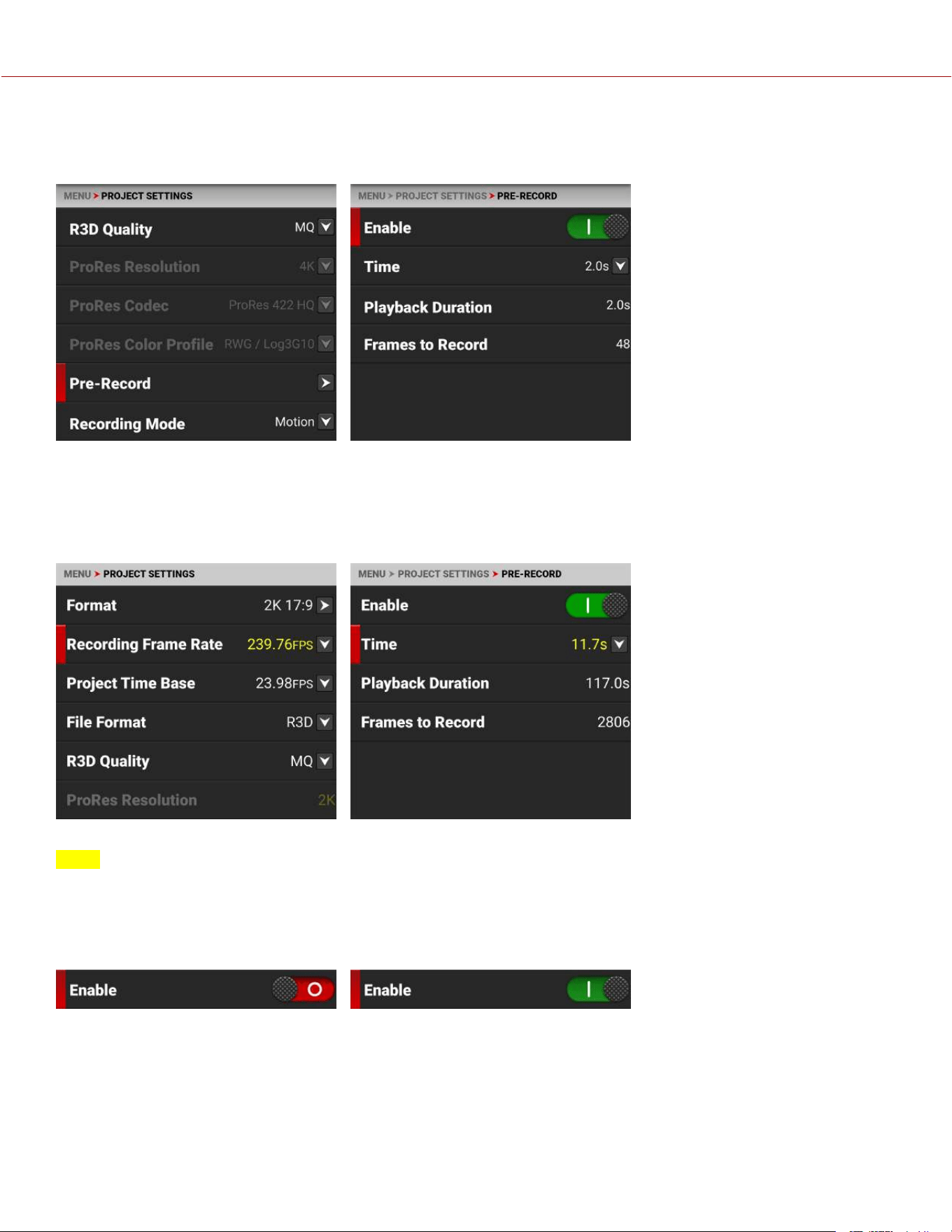
PRE-RECORD
Use the Pre-Record menu to enable or disable Pre-Record, and to adjust the length of the Pre-Recorded clip.
Pre-Record allows you to continually capture images to a small amount of memory while waiting to begin recording.
This allows you to capture unexpected events such as, a whale breaching the water, or an athlete scoring a goal. When
you finish recording, the pre-recorded clip is added to the beginning of the recording.
You can set the Pre-Record clip to record from half a second up to 30 seconds, depending on the format, file type,
resolution, and quality. The default setting is 2 seconds at the default Project Time Base of 23.98 FPS.
When the selected pre-record time is not possible in the selected format, the closest time available will be shown in
yellow.
For more information, refer to Pre-Recording Content.
ENABLE
Select Enable to toggle Pre-Record on and off.
COPYRIGHT © 2023 RED.COM, LLC 955-0218, REV A | 71
KOMODO-X
®
OPERATION GUIDE
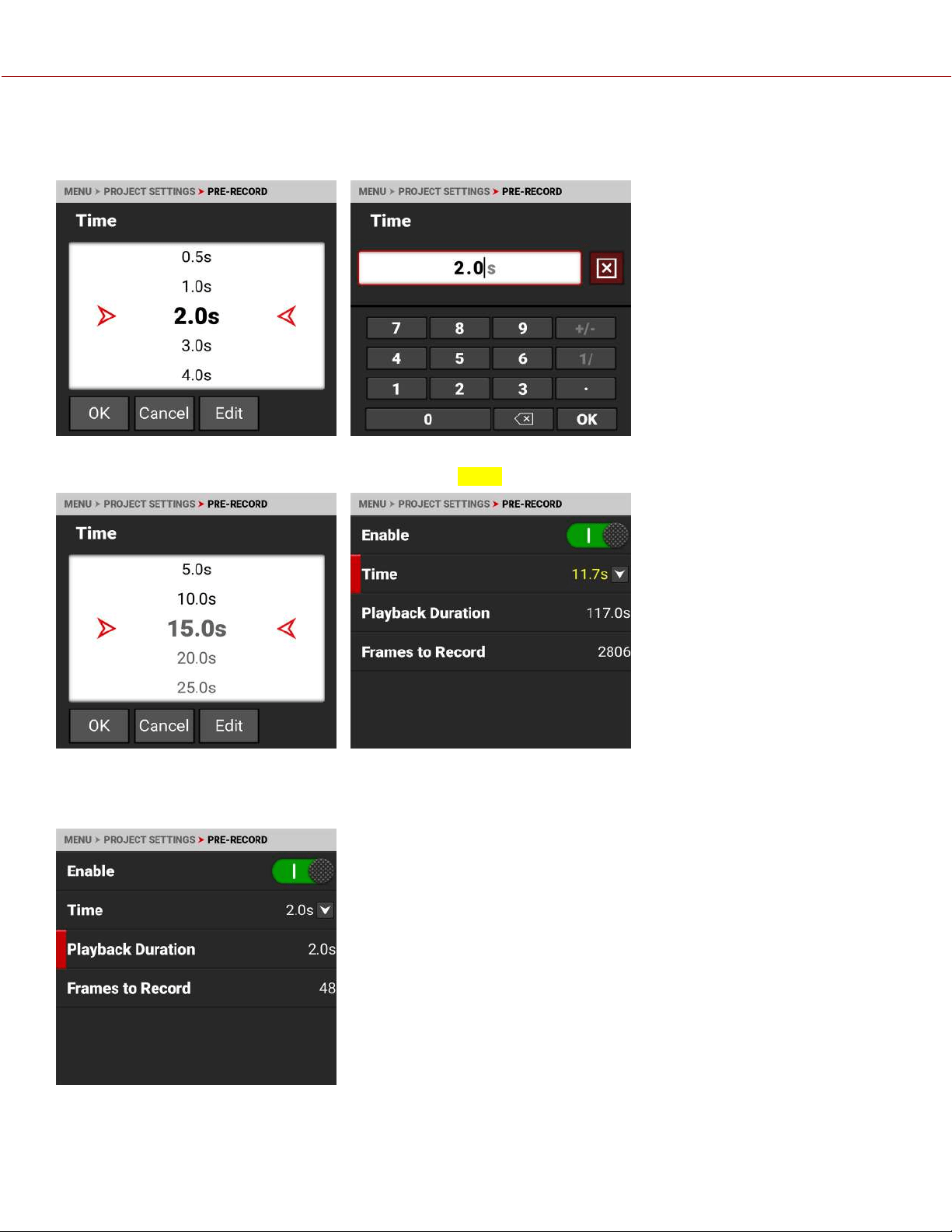
TIME
Select Time to choose or enter the number of seconds to pre-record.
When you select a Time value larger than the current settings allow, the camera changes the Time value to the
maximum value it can support and highlights the value in yellow.
PLAYBACK DURATION
Playback Duration displays the duration in seconds that the pre-record clip will last in playback.
COPYRIGHT © 2023 RED.COM, LLC 955-0218, REV A | 72
KOMODO-X
®
OPERATION GUIDE
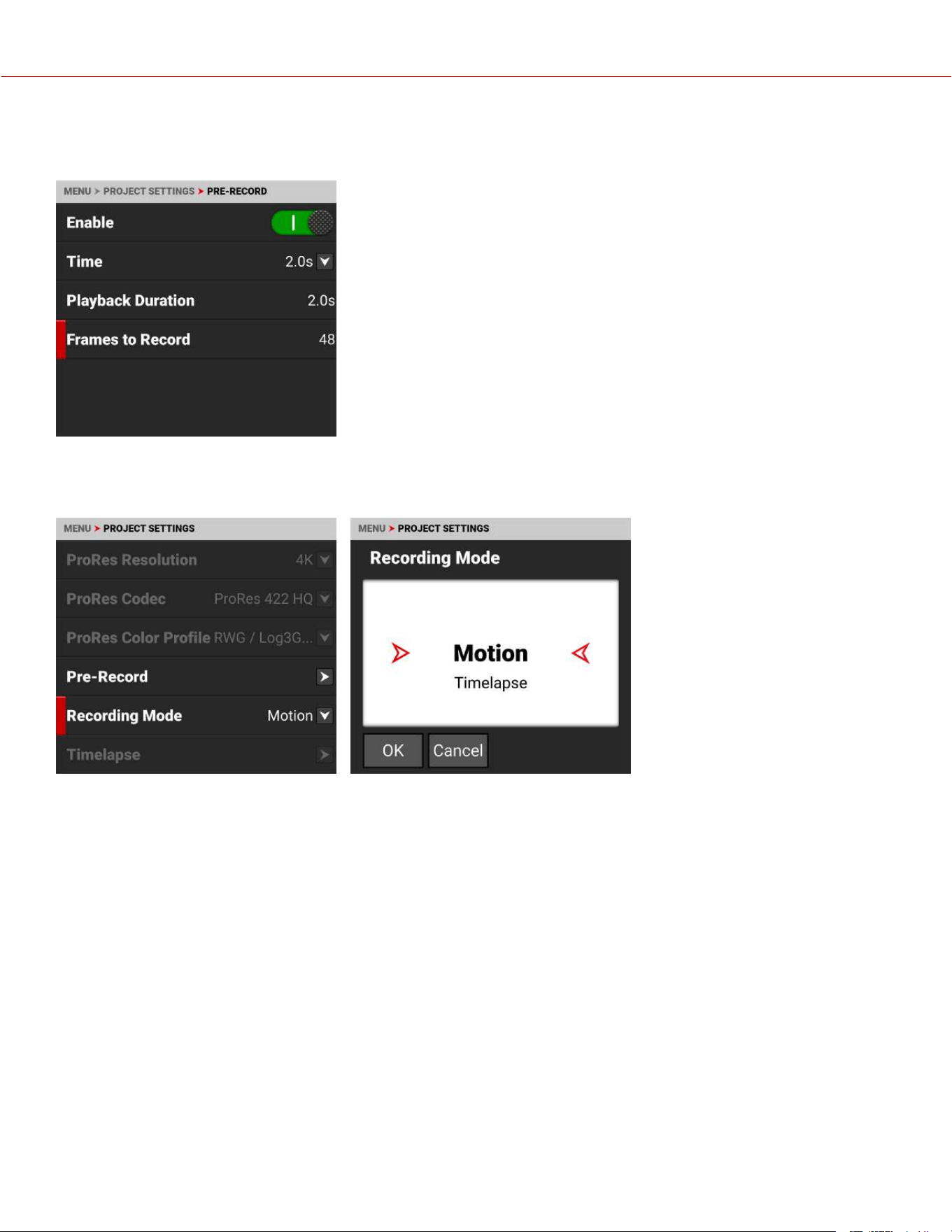
FRAMES TO RECORD
Frames to Record displays the number of frames the pre-recorded clip will contain at the current settings.
RECORDING MODE
Use Recording Mode to select between normal motion recording or timelapse recording.
When you select Timelapse, the Timelapse option is enabled on the menu.
COPYRIGHT © 2023 RED.COM, LLC 955-0218, REV A | 73
KOMODO-X
®
OPERATION GUIDE
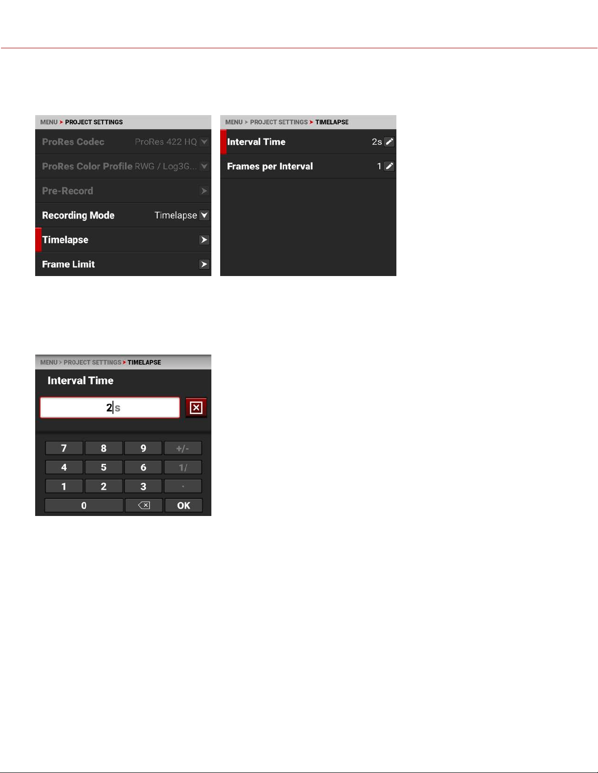
TIMELAPSE
Use Timelapse to select the timelapse settings.
From Timelapse you can select the interval time between the group of frames per interval, and you can select the
number of frames captured per interval.
INTERVAL TIME
Select Interval Time to enter the elapsed time between the group of frames per interval.
For example:
60s = 1 minute
3600s = 1 hour
86400s = 1 day
COPYRIGHT © 2023 RED.COM, LLC 955-0218, REV A | 74
KOMODO-X
®
OPERATION GUIDE

FRAMES PER INTERVAL
Select Frames Per Interval to enter the number of frames to record per interval.
Adding more frames per interval allows you to have more flexibility in post (for example: image stacking).
FRAME LIMIT
Use Frame Limit to limit the total number of frames recorded per clip. Frame limit applies to both Motion and Timelapse
recording modes.
The Frame Limit selections include Enable, Frames, and Playback Duration.
ENABLE
Select Enable to toggle the activation of the Frame Limit feature.
COPYRIGHT © 2023 RED.COM, LLC 955-0218, REV A | 75
KOMODO-X
®
OPERATION GUIDE
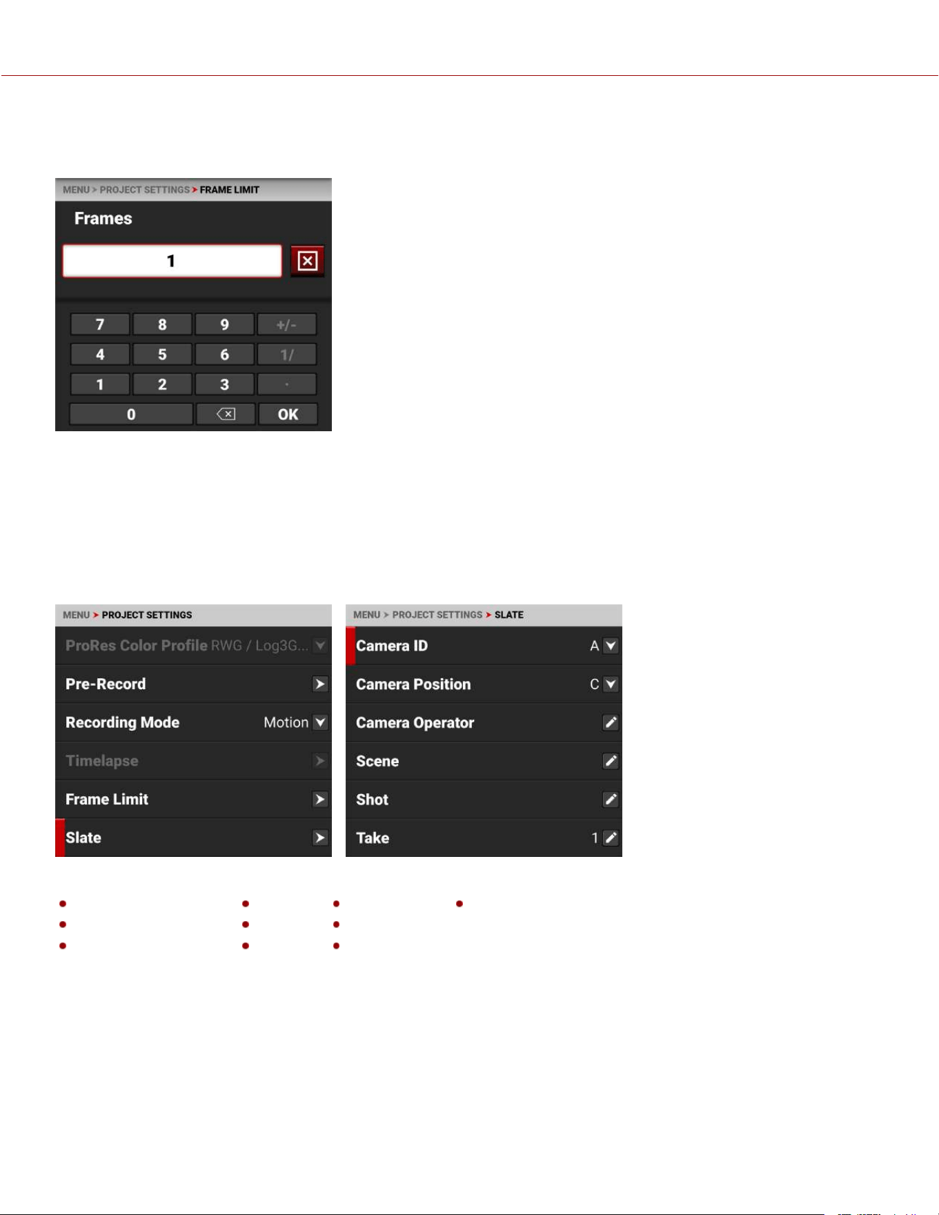
FRAMES
Use frames to enter the maximum number of frames the clip can record.
PLAYBACK DURATION
Playback Duration displays the calculated playback duration of the clip with the selected Frame Limit and FPS.
For example, using 1440 Frames as a Frame Limit at 24 FPS results in one minute of playback duration.
SLATE
Use the Slate menu to assign a camera ID and camera position to the clip.
The information you can add to a clip includes:
Camera ID Scene Production Unit
Camera Position Shot Director
Camera Operator Take DoP
NOTE: When you set the Camera ID and Camera Position, they are also set in the Media>Secure Format menu items.
COPYRIGHT © 2023 RED.COM, LLC 955-0218, REV A | 76
KOMODO-X
®
OPERATION GUIDE
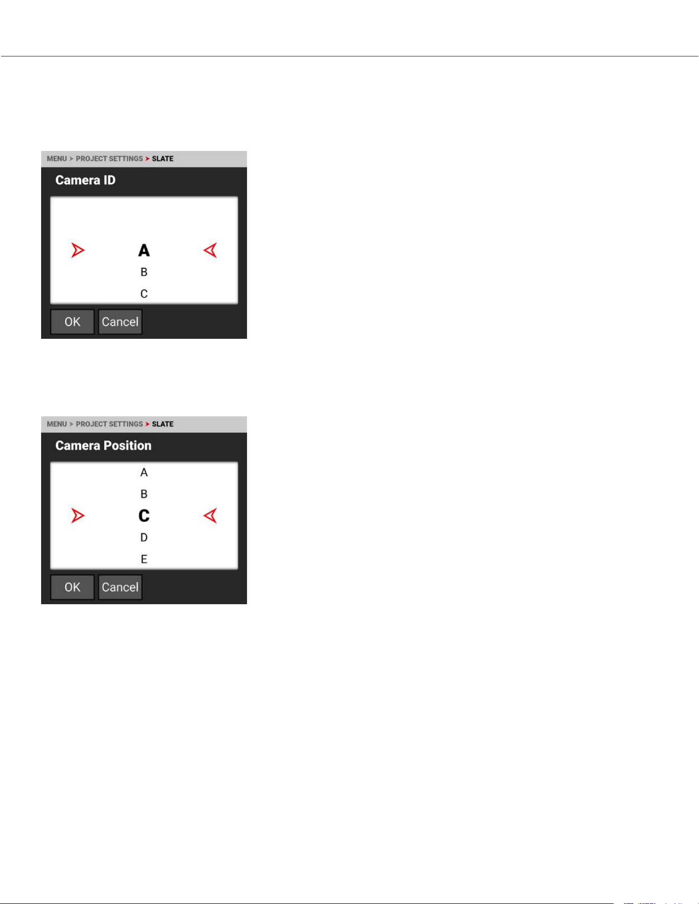
CAMERA ID
Use Camera ID to assign a camera ID when the camera records clips.
NOTE: You can also change the Camera ID by using Secure Format (refer to Secure Format).
The camera IDs you can assign when recording a clip include the letters A-Z.
CAMERA POSITION
Use Camera Position to assign a camera position letter when the camera records clips.
The camera positions you can assign when recording a clip include the letters A-Z.
COPYRIGHT © 2023 RED.COM, LLC 955-0218, REV A | 77
KOMODO-X
®
OPERATION GUIDE
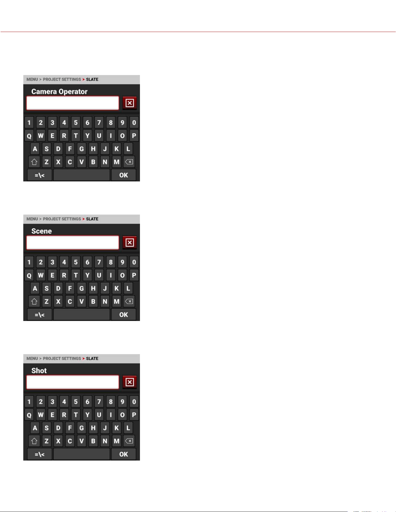
CAMERA OPERATOR
Use Camera Operator to enter the name of the camera operator.
SCENE
Use Scene to enter the scene name.
SHOT
Use Shot to enter the number of the shot.
COPYRIGHT © 2023 RED.COM, LLC 955-0218, REV A | 78
KOMODO-X
®
OPERATION GUIDE
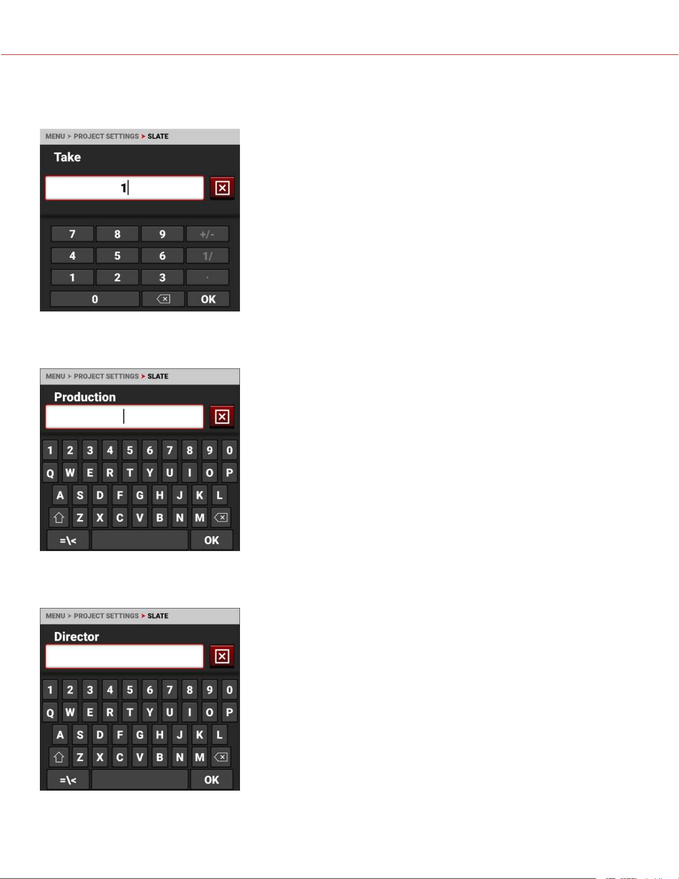
TAKE
Use Take to enter the number of the take.
PRODUCTION
Use Production to enter the name of the production.
DIRECTOR
Use Director to enter the name of the director.
COPYRIGHT © 2023 RED.COM, LLC 955-0218, REV A | 79
KOMODO-X
®
OPERATION GUIDE
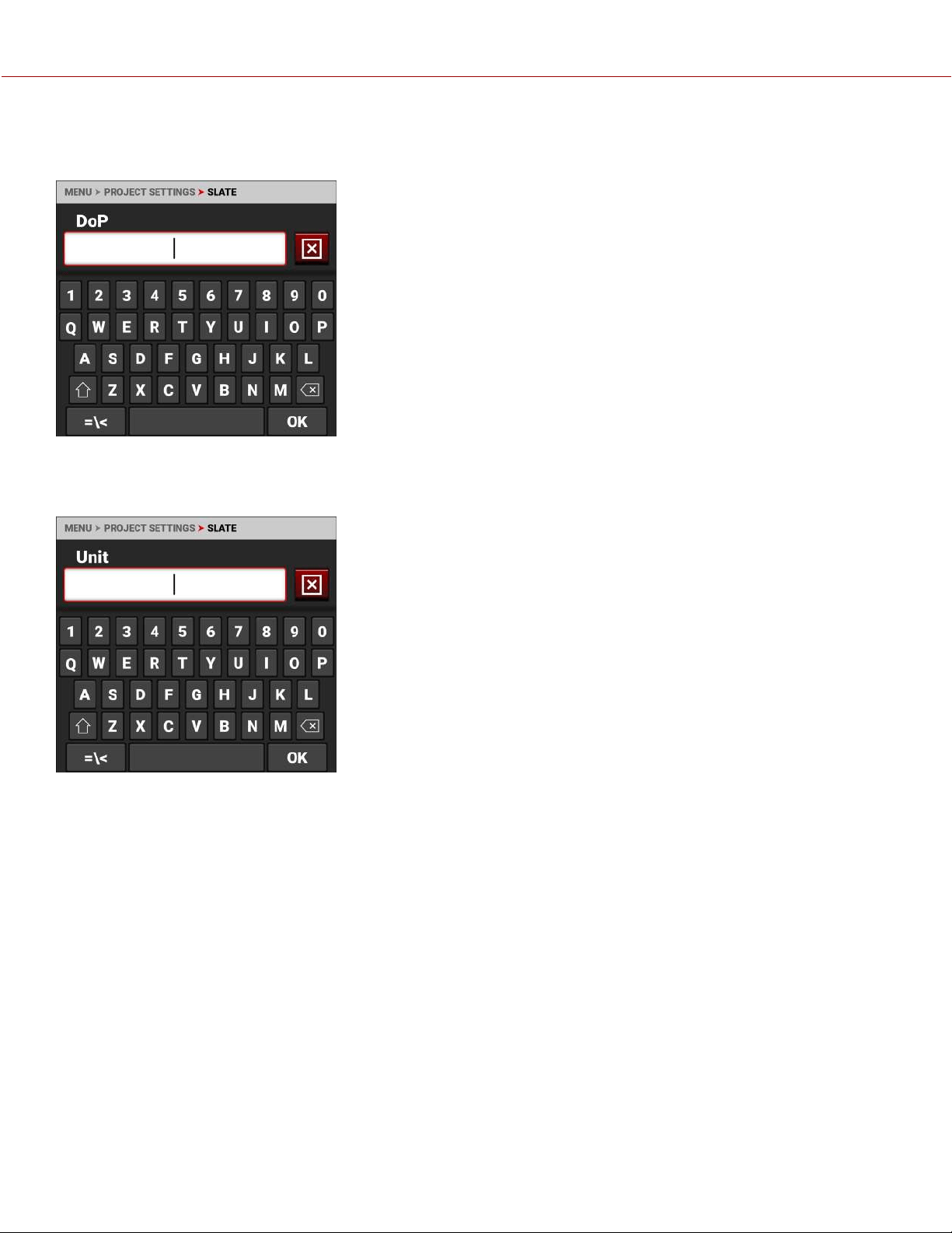
DOP
Use DoP to enter the name of the director of photography.
UNIT
Use Unit to enter the name of the production unit.
COPYRIGHT © 2023 RED.COM, LLC 955-0218, REV A | 80
KOMODO-X
®
OPERATION GUIDE
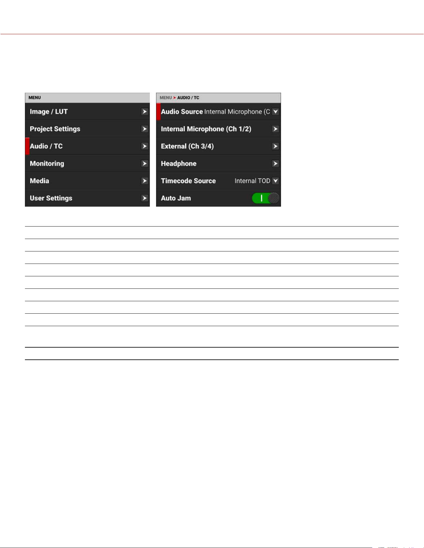
AUDIO / TC MENU
The Audio / TC menu contains the settings you use to configure your camera audio and Timecode.
From the Onboard LCD touchscreen menu, select Audio / TC:
Use the Audio / TC menu to configure the audio and Timecode settings for the camera:
ITEM DETAILS
Audio Source Audio input source
Internal Microphone (Ch 1/2) Left and right internal microphone levels
External (Ch 3/4) Left and right external audio levels
Headphone Headphone volume level
Timecode Source Timecode source
Auto Jam Button to enable auto-jamming Timecode to time-of-day (TOD) Timecode
Jam Timecode to TOD Button to jam Timecode to time-of-day (TOD)
Manual Timecode Button to jam to the camera's internal Timecode generator and edit the
Timecode starting number
Timecode Display Mode Timecode type to display
AUDIO DETAILS
The camera is equipped with two integrated microphones suitable for scratch-track audio (Ch 1 and 2), and it is
equipped with a 5-Pin ODU audio connector that accepts 2-channel audio, which is configurable for Line or Mic level
inputs, and can provide +48V Phantom power (Ch 3 and 4).
You can link the gain for the two internal channels together and you can link the two external channels together. This
allows you to adjust the two internal (or external) channels together as one.
You can record audio from the internal microphones, from the external audio connector (2-channel recording), or from
internal and external sources combined as four 24-bit 48 kHz uncompressed audio tracks.
You can adjust the external audio by using the appropriate camera gain-settings. The default camera gain setting is 1
dB.
The camera's audio data is synchronized with video and timecode, and it is embedded in the R3D file. You can export
the audio data as separate audio files by using REDCINE-X PRO, if needed. The camera also embeds the audio in the
SDI output.
You can monitor the audio during recording and playback by using the equipped 3.5 mm stereo headphone port.
COPYRIGHT © 2023 RED.COM, LLC 955-0218, REV A | 81
KOMODO-X
®
OPERATION GUIDE
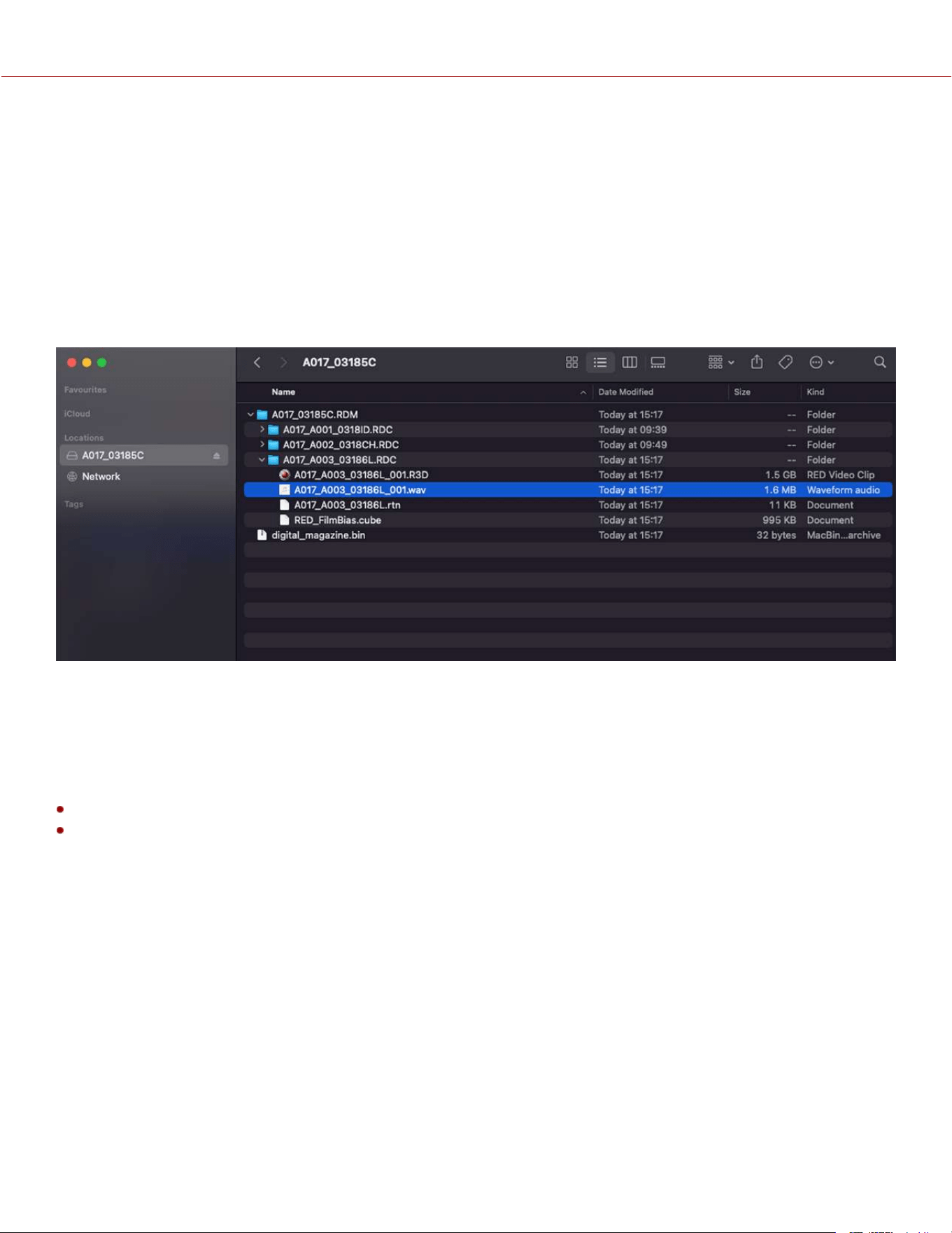
SDI AUDIO
When you select Internal Microphone (Ch 1/2) as the audio source, the camera routes the Internal Microphone signals to
SDI channels 1 and 2. When you select External (Ch 3/4), the camera routes the External audio signal to SDI channels 1
and 2. When you select Internal + External, the camera routes the Internal Microphone signal to SDI channels 1 and 2,
and the External Audio signal to SDI channels 3 and 4.
VARISPEED AUDIO
This camera has the ability to record audio when the camera's Recording Frame Rate is set to a higher speed than the
Project Time Base setting (Varispeed mode).
NOTE: The camera records the audio as a separate WAV file and stores it in the clip's RDC folder on the media drive.
TIMECODE DETAILS
Timecode provides a mechanism to reference frames from the camera's recorded clips to external devices, such as
other cameras or audio recorders. Some devices can also gather additional data such as, lens metadata, or camera
orientation, which Timecode can later use for merging the data back together in post-processing.
The camera provides two separate Timecode formats:
Time Of Day (TOD) - The camera records the time of day as the Timecode for each clip
Edgecode - The camera records elapsed time as the Timecode for each clip. The time is reset to 01:00:00 when a
new media card is inserted in the camera. All of the clips on the media will have a continuous Timecode track.
However, each new media card will default to a Timecode track starting at 01:00:00. Edgecode is equivalent to RUN
RECORD as used on broadcast cameras. You can change the Edgecode to begin at any desired time by using the
Media Format menu (refer to Edgecode).
The camera synchronizes (jams) the TOD Timecode to an external Timecode generator (when one is connected to the
camera) or it jams the Timecode to its internal real-time clock.
When using Internal TOD, a jam between the running timecode and a real time clock is required. The time at which this
jam occurs will have an effect on the overall timecode drift over a 24-hour period due to the nature of non-drop-frame
(NDF) timecode. By enabling Auto-Jam, the camera automatically jams its timecode, ensuring repeatable drift across
multiple cameras and days.
When Auto Jam is disabled, you can manually pick the instant in which you want to jam timecode to the real time clock.
The camera stores TOD and Edge Timecode in the R3D file. You can select which one you want to display on the side
LCD (refer to Timecode Display Mode).
COPYRIGHT © 2023 RED.COM, LLC 955-0218, REV A | 82
KOMODO-X
®
OPERATION GUIDE
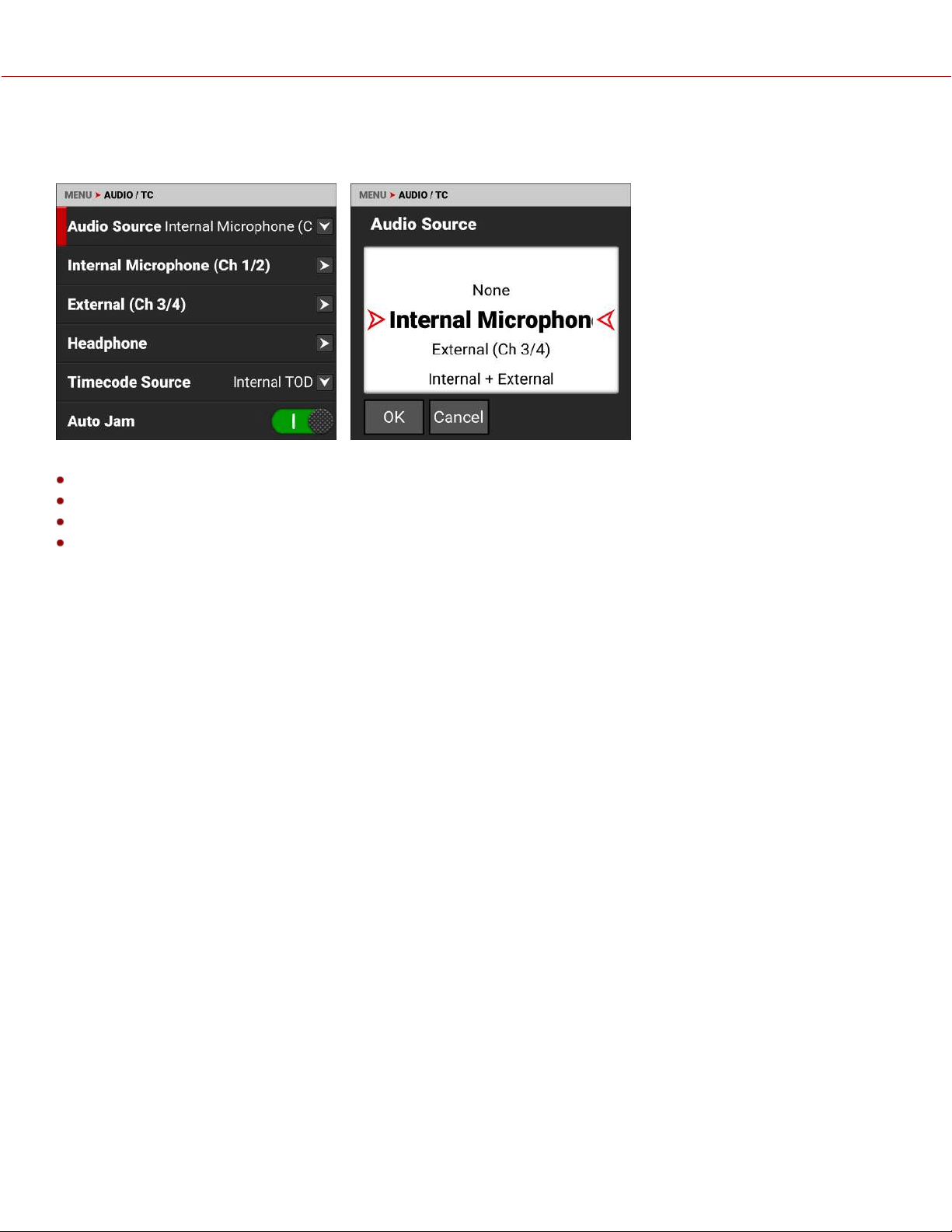
AUDIO SOURCE
Use the Audio Source settings to select the audio input source.
The audio input sources include:
None
Internal Microphone - enables the Internal Microphone channels 1 and 2 (default)
External - enables the 5-pin 00B Audio Input port for External Audio channels 3 and 4
Internal and External - enables the Internal Microphone and the 5-pin 00B Audio Port for all channels 1 through 4.
NOTE: The headphones can only monitor two channels. You can either monitor channels 1 and 2 (internal
microphone) or you can monitor channels 3 and 4 (external port). Refer to Audio Tools for more information.
COPYRIGHT © 2023 RED.COM, LLC 955-0218, REV A | 83
KOMODO-X
®
OPERATION GUIDE
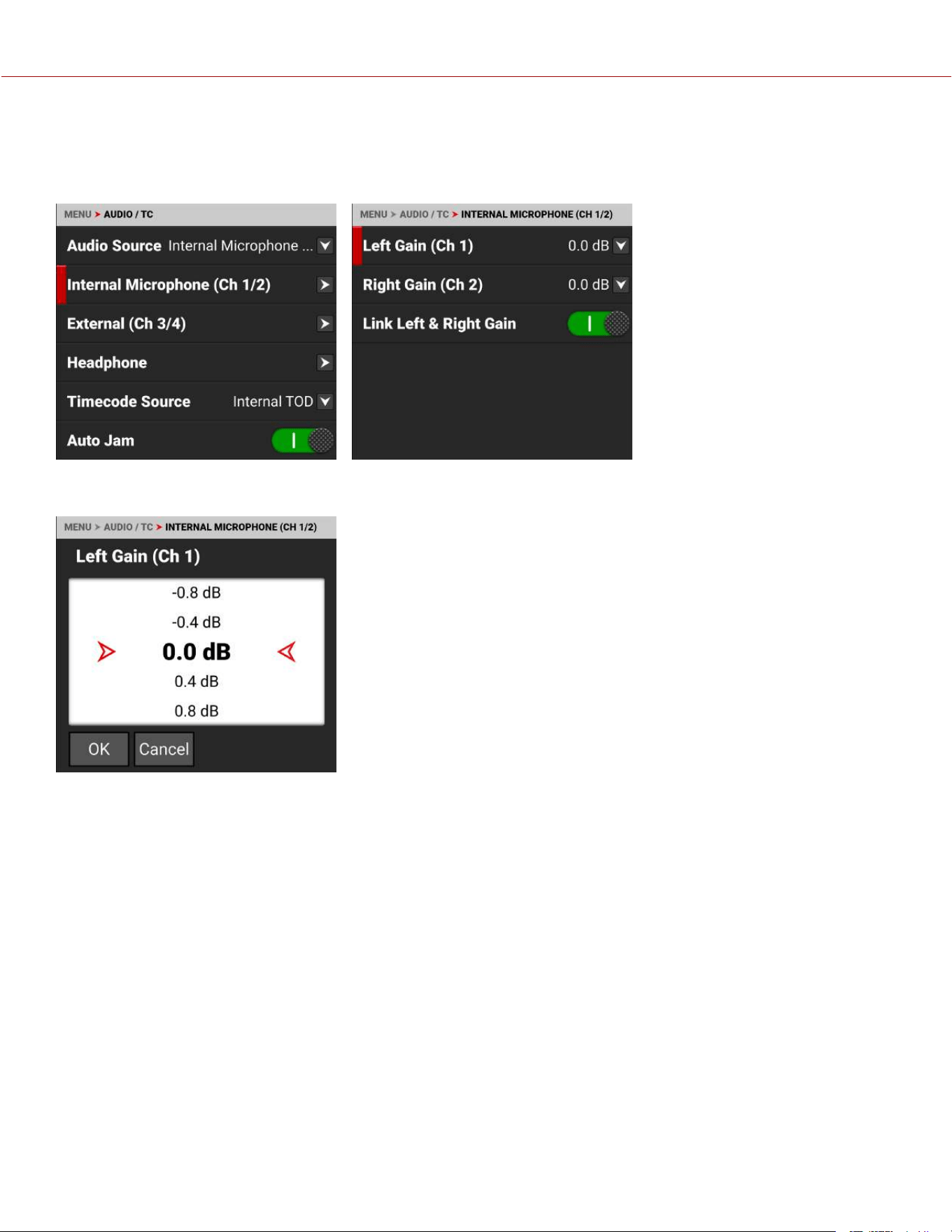
INTERNAL MICROPHONE
Use the Internal Microphone settings to set the left and right internal microphone levels. This menu is only enabled when
the Audio Source is set to Internal Microphone or Internal and External.
The Internal Microphone is represented as Channels 1 and 2 on the UI VU Meters (refer to Playback for more
information). The left channel is channel 1 (Ch 1) and the right channel is channel 2 (Ch 2).
You can adjust the internal audio levels for left and right from -52.5 dB to 36.0 dB.
The default setting is 0 dB.
When you enable Link Left & Right Gain, the adjustments you make to either channel of gain will adjust both channels to
the same setting.
COPYRIGHT © 2023 RED.COM, LLC 955-0218, REV A | 84
KOMODO-X
®
OPERATION GUIDE
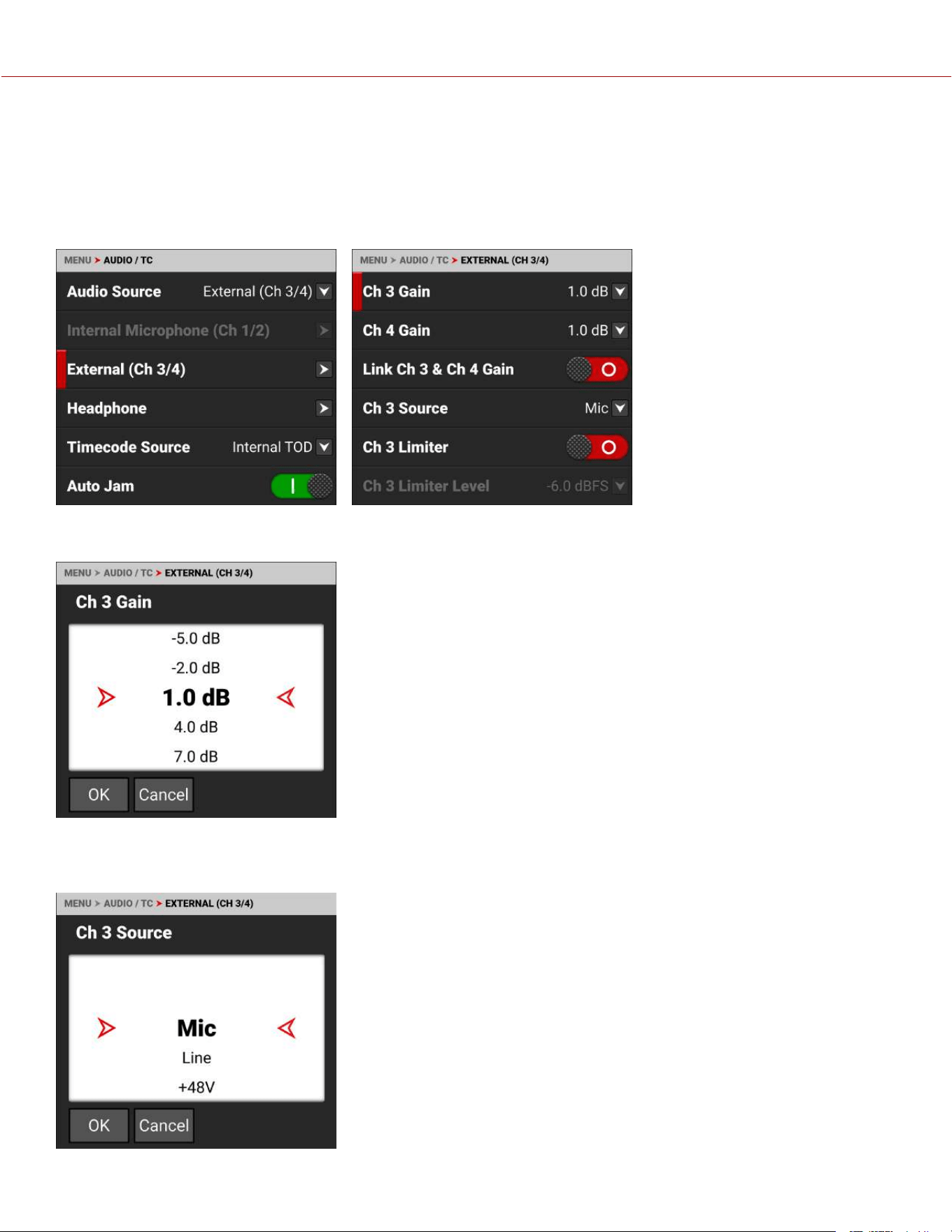
EXTERNAL AUDIO
Use the External Audio settings to set the left and right external audio levels. This menu is only enabled when the Audio
Source is set to External or set to Internal and External.
NOTE: When the Recording Frame Rate is set to a higher speed than the Project Time Base setting, audio is recorded
as varispeed audio.
The External Microphone is represented as Channels 3 and 4 on the UI VU Meters (refer to Playback for more
information).
You can adjust the external audio levels for Ch 3 and Ch 4 from -8.0 dB to
34.0 dB.
The default setting is 1.0 dB.
When you enable Link Ch 3 & Ch 4 Gain, the adjustments you make to either
channel of gain will adjust both channels to the same setting.
SOURCE
Use Source to select the type of input connected to external audio channel 3 and 4 ports.
You can select microphone, line, or +48V phantom power.
The default setting is microphone (Mic).
COPYRIGHT © 2023 RED.COM, LLC 955-0218, REV A | 85
KOMODO-X
®
OPERATION GUIDE
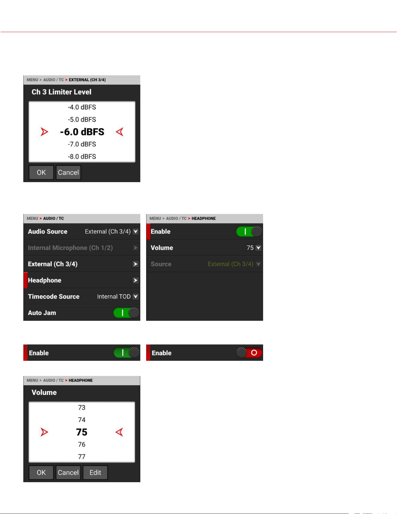
LIMITER
When enabled, use the limiter to place a limit past which the audio level for channels 3 and 4 cannot exceed.
You can select from -2.0 to -12.0 Decibel Full Scale (dBFS) as the limit.
The default limit is -6.0 dBFS.
HEADPHONE
Use the Headphone settings to enable the headphone jack and to adjust the headphone volume.
You can enable and disable the headphone audio jack by tapping the Enable toggle to the right (green) and to the left
(red).
You can adjust the headphone volume from 0 to 100. The default is 75.
COPYRIGHT © 2023 RED.COM, LLC 955-0218, REV A | 86
KOMODO-X
®
OPERATION GUIDE
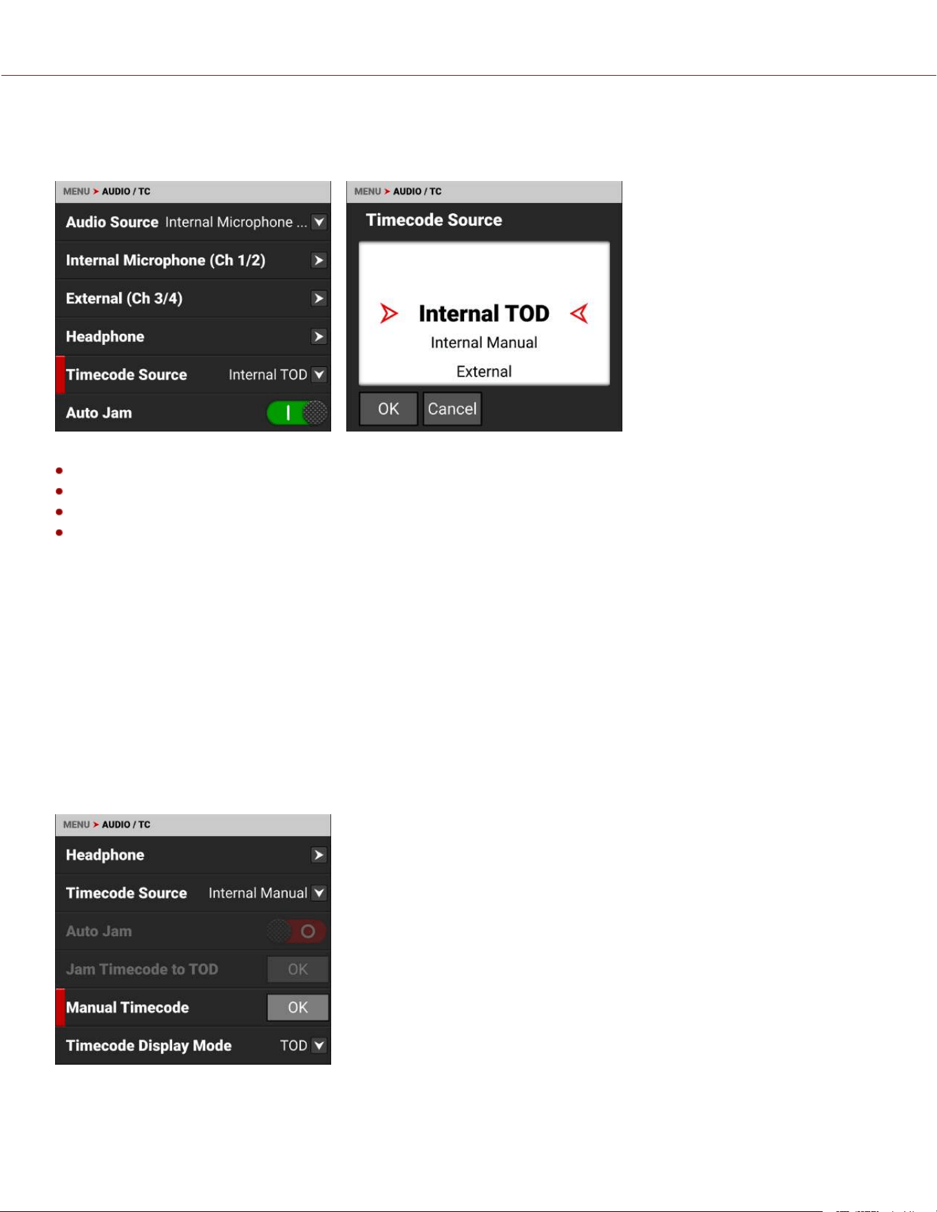
TIMECODE SOURCE
Use Timecode source to configure the Timecode source the camera applies to the recordings.
You can select the following Timecode sources:
Internal Time of Day (TOD)
Internal Manual
External
Precision Time Protocol (PTP)
INTERNAL TOD
Use Internal Time of Day (TOD) to JAM to the camera's internal Timecode generator. When using Internal TOD, a jam
between the running timecode and a real time clock is required. The time at which this jam occurs will have an effect on
the overall timecode drift over a 24-hour period due to the nature of non-drop-frame (NDF) timecode.
By enabling Auto-Jam, the camera automatically jams its timecode, ensuring repeatable drift across multiple cameras
and days. When Auto Jam is disabled, you can manually pick the instant in which you want to jam timecode to the real
time clock.
INTERNAL MANUAL
Use Internal Manual to JAM to the camera's internal Timecode generator and edit the Timecode starting number.
Select Manual Timecode OK to open the JAM and editing options:
COPYRIGHT © 2023 RED.COM, LLC 955-0218, REV A | 87
KOMODO-X
®
OPERATION GUIDE
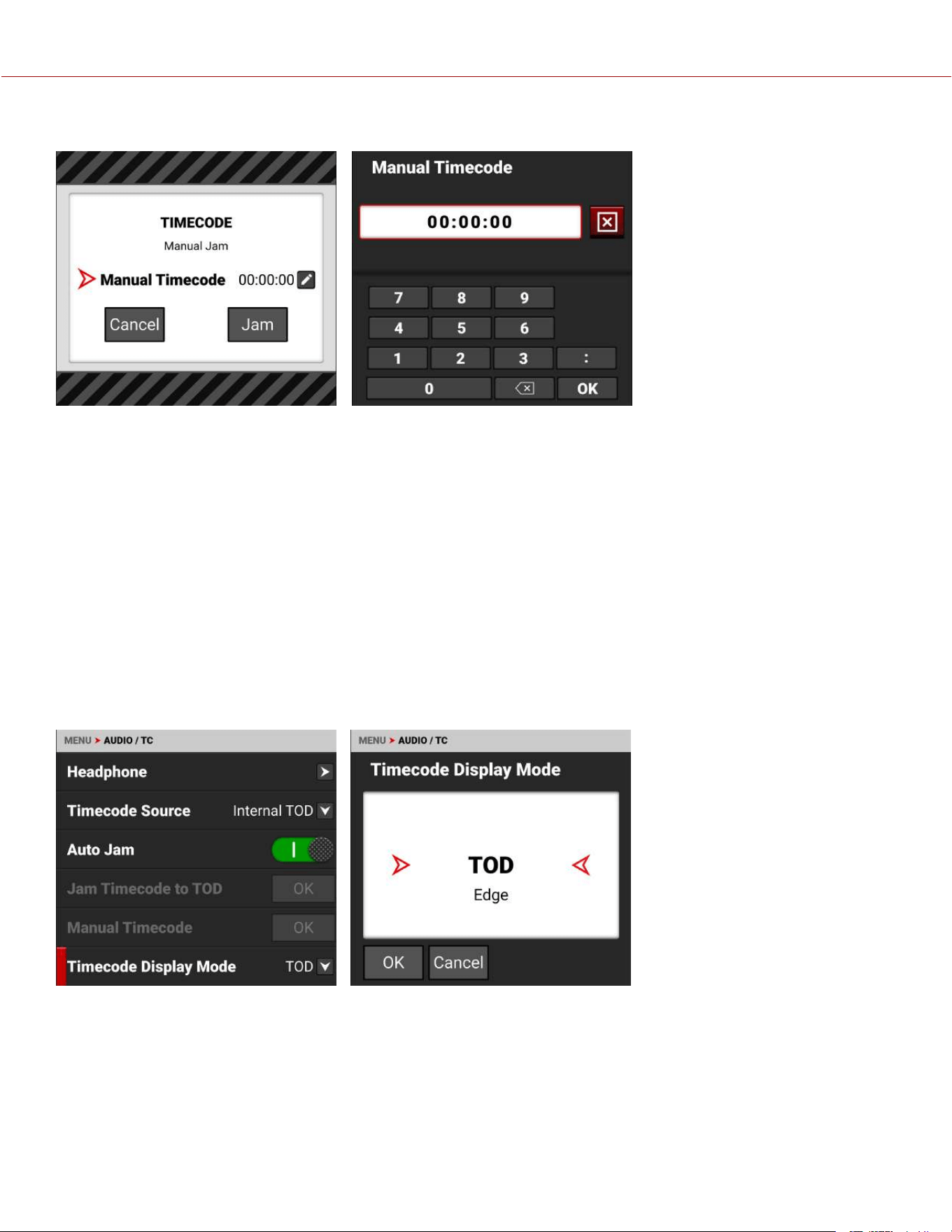
Select JAM to jam to the internal Timecode or select Manual Timecode to open the editing screen:
Enter the desired Timecode number and select OK. Select JAM to jam to the edited Timecode number.
EXTERNAL
Use External to connect an external Timecode generator to the 9-contact 0B Extension port (refer to Camera Body and
Extension Port for more information).
PRECISION TIME PROTOCOL (PTP)
Precision Time Protocol (SMPTE 2059-1) is a network-based synchronization method which when configured using a
USB-C to Ethernet adapter offers a level of precision that supports frame-accurate camera synchronization over IP. PTP
in the KOMODO-X camera body only offers frame-level precision and therefore cannot be used for sensor scan
synchronization. PTP Timecode can be sent over USB-C through an Ethernet adapter.
TIMECODE DISPLAY MODE
Use Timecode Display Mode to configure the Timecode display type that the camera applies to the recordings.
You can set the Timecode Display Mode as Time of Day (TOD) or Edge.
TOD DISPLAY MODE
Time of Day (TOD) display mode displays the Timecode as the time of day that the frame was recorded.
EDGE DISPLAY MODE
Edge display mode displays the Timecode as the sequential recording time that has elapsed starting with the first
frame.
COPYRIGHT © 2023 RED.COM, LLC 955-0218, REV A | 88
KOMODO-X
®
OPERATION GUIDE
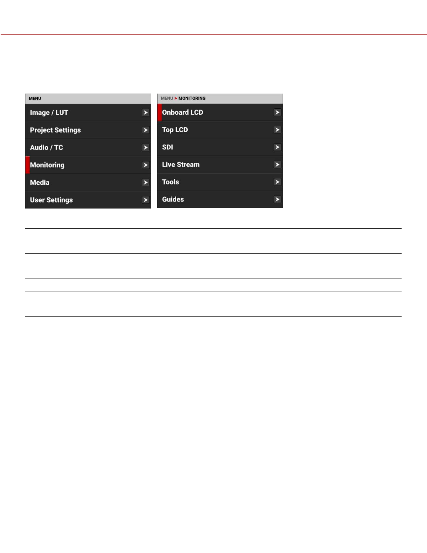
MONITORING MENU
The Monitoring menu contains the settings you use to configure your camera monitoring options.
From the Onboard LCD Touchscreen menu, select Monitoring:
Use the Monitoring menu to configure the monitoring settings:
ITEMS DETAILS
Onboard LCD Onboard LCD Touchscreen settings
Top LCD DSMC3™ RED® Touch 7.0" LCD settings
SDI SDI port resolution, frequency, look, guides, tools, overlay, and overlay mode
Live Stream Enable or disable Wi-Fi live streaming
Tools Various monitoring tools including False Color, Peaking, and Zebra Modes
Guides Frame guides and a center guide
COPYRIGHT © 2023 RED.COM, LLC 955-0218, REV A | 89
KOMODO-X
®
OPERATION GUIDE
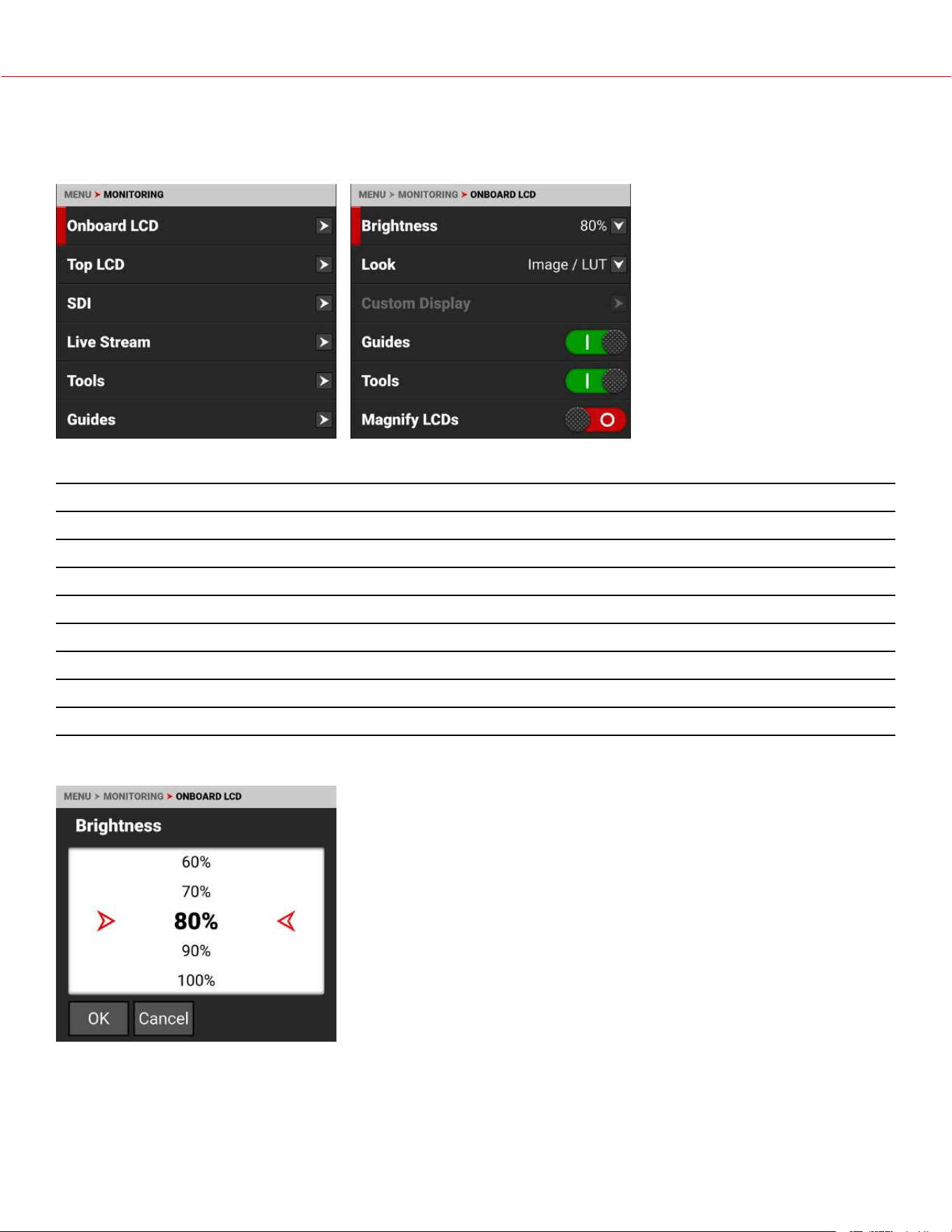
ONBOARD LCD
Use Onboard LCD to configure the Onboard LCD Touchscreen settings.
The LCD settings you can configure include:
ITEMS DETAILS
Brightness Adjust the Onboard LCD touchscreen brightness
Look Select the Image / LUT, RWG, Log3G10, or a Custom Display image preview
Custom Display Configure the Custom Display settings when enabled
Guides Enable or disable the camera guides
Tools Enable or disable the camera tools
Magnify LCDs Enable or disable LCDs magnification
Magnify Position (Global) Select the magnification area position
Prism Finder Mode Enable or disable the prism finder mode (horizontally flip the LCD)
BRIGHTNESS
You can adjust the camera's top LCD brightness from 10% to 100%. The default is 80%
COPYRIGHT © 2023 RED.COM, LLC 955-0218, REV A | 90
KOMODO-X
®
OPERATION GUIDE

LOOK
You can select the look of the image preview signal sent to the Top
LCD.
The selections include:
• Image / LUT (default)
• REDWideGamutRGB / Log3G10
• Custom Display (enables the Custom Display menu)
CUSTOM DISPLAY
Use Custom Display (enabled from the Look menu) to select the Onboard
LCD's Image/LUT settings.
Refer to Image / LUT Menu for more information about the specific look
settings and menus.
GUIDES
Use the toggle to enable (default) or disable the camera guides.
COPYRIGHT © 2023 RED.COM, LLC 955-0218, REV A | 91
KOMODO-X
®
OPERATION GUIDE
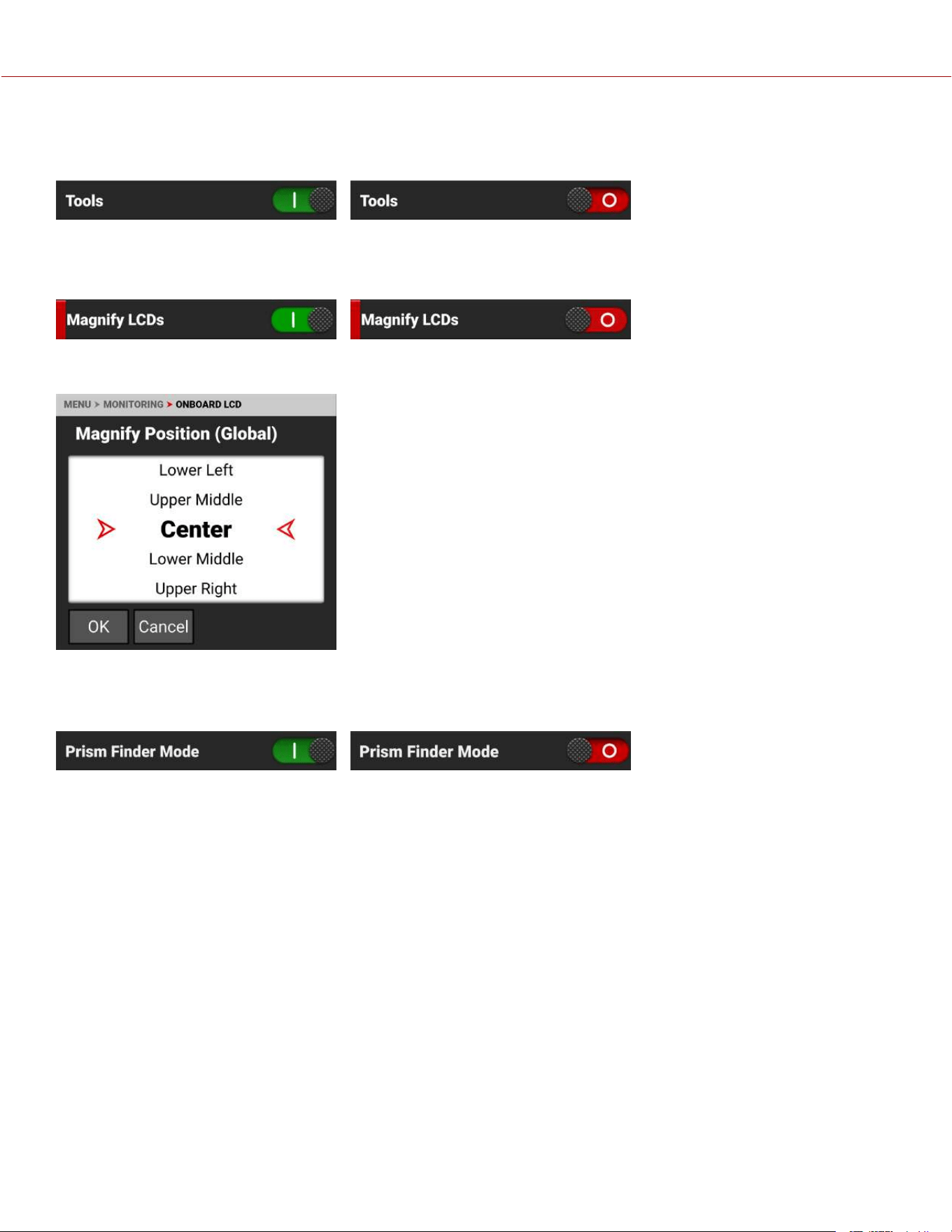
TOOLS
Use the toggle to enable (default) or disable the camera tools.
MAGNIFY LCDS
Use the toggle to enable or disable (default) Onboard LCD and Top LCD magnification.
MAGNIFY POSITION (GLOBAL)
Use Magnify Position (Global) to select the position of the magnified area for
all LCD magnification.
PRISM FINDER MODE
Use the toggle to enable or disable (default) the LCD flip view.
COPYRIGHT © 2023 RED.COM, LLC 955-0218, REV A | 92
KOMODO-X
®
OPERATION GUIDE
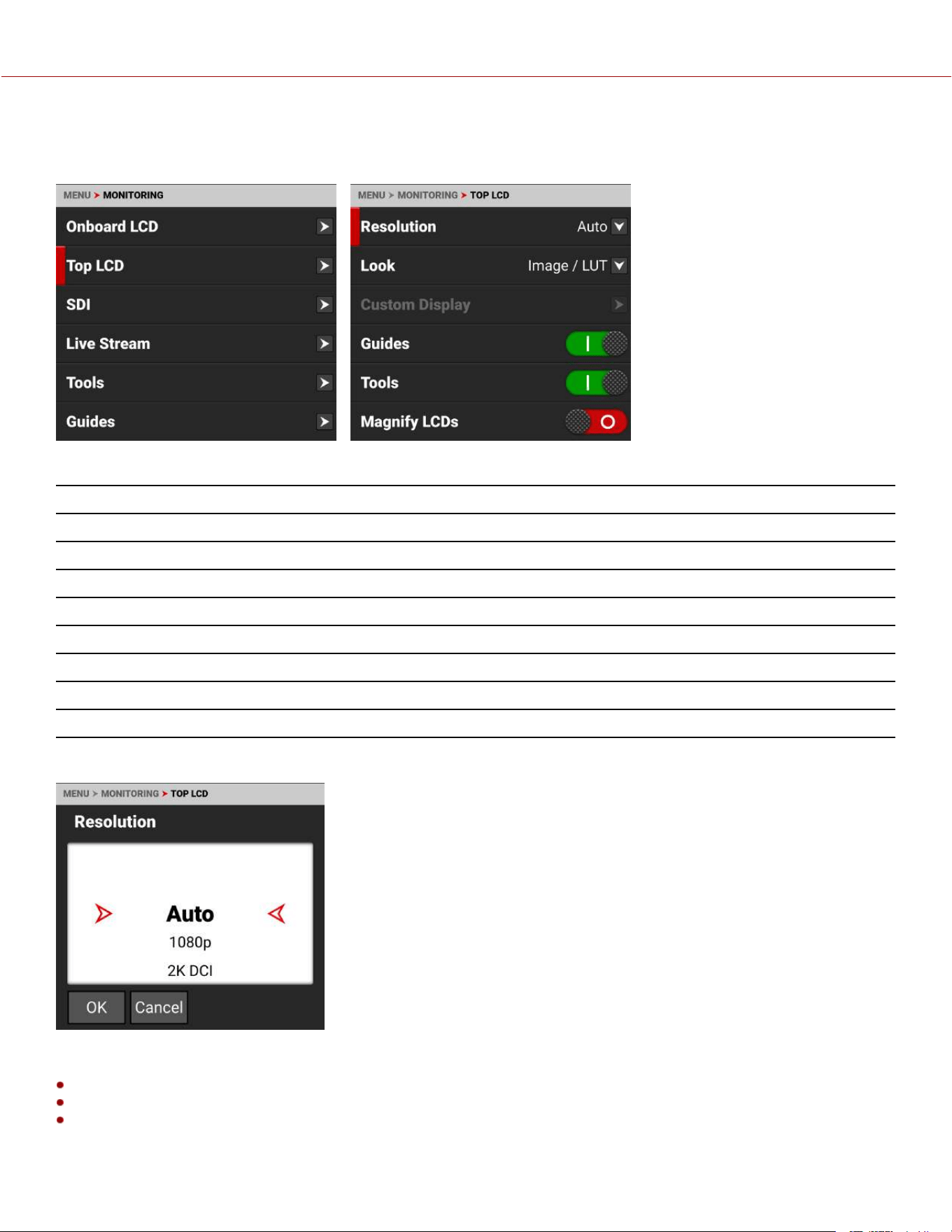
TOP LCD
Use Top LCD to configure the DSMC3™ RED® Touch 7.0" LCD settings.
The LCD settings you can configure include:
ITEMS DETAILS
Resolution Adjust the RED® Touch 7.0" LCD resolution
Look Select the Image / LUT, RWG, Log3G10, or a Custom Display image preview
Custom Display Configure the Custom Display settings when enabled
Guides Enable or disable the camera guides
Tools Enable or disable the camera tools
Magnify LCDs Enable or disable LCD magnification
Magnify Position (Global) Select the LCD magnification area position
Prism Finder Mode Enable or disable the prism finder mode (horizontally flip the LCD)
RESOLUTION
You can select the resolution of the Top LCD.
The selections include:
Auto (default)
1080p
2K DCI
COPYRIGHT © 2023 RED.COM, LLC 955-0218, REV A | 93
KOMODO-X
®
OPERATION GUIDE
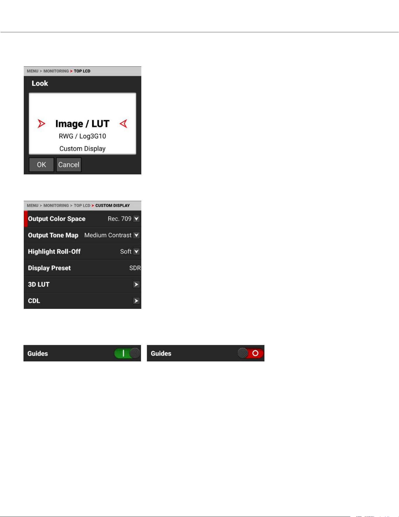
LOOK
You can select the look of the image preview signal sent to the Top LCD.
The selections include:
• Image / LUT (default)
• REDWideGamutRGB / Log3G10
• Custom Display (enables the Custom Display menu)
CUSTOM DISPLAY
Use Custom Display to configure the Top LCD independently of the
camera's Image / LUT settings or other monitor output configurations.
Refer to Image / LUT Menu for more information about the Image/LUT
settings and menus.
GUIDES
Use the toggle to enable (default) or disable the camera guides.
COPYRIGHT © 2023 RED.COM, LLC 955-0218, REV A | 94
KOMODO-X
®
OPERATION GUIDE
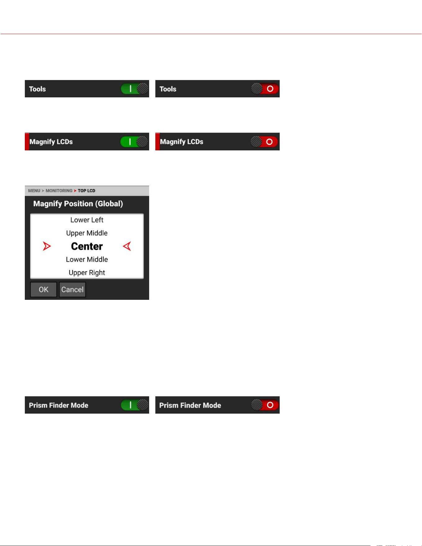
TOOLS
Use the toggle to enable (default) or disable the camera tools.
MAGNIFY LCDS
Use the toggle to enable or disable (default) LCD magnification.
MAGNIFY POSITION (GLOBAL)
Use Magnify Position (Global) to select the position of the magnified area for all LCD magnification.
Use Magnify Position to globally select the area of the image you want to magnify.
The selections include:
• Left • Upper Middle • Upper Right
• Upper Left • Center (default) • Lower Right
• Lower Left • Lower Middle • Right
PRISM FINDER MODE
Use the toggle to enable or disable (default) the LCD flip view.
COPYRIGHT © 2023 RED.COM, LLC 955-0218, REV A | 95
KOMODO-X
®
OPERATION GUIDE
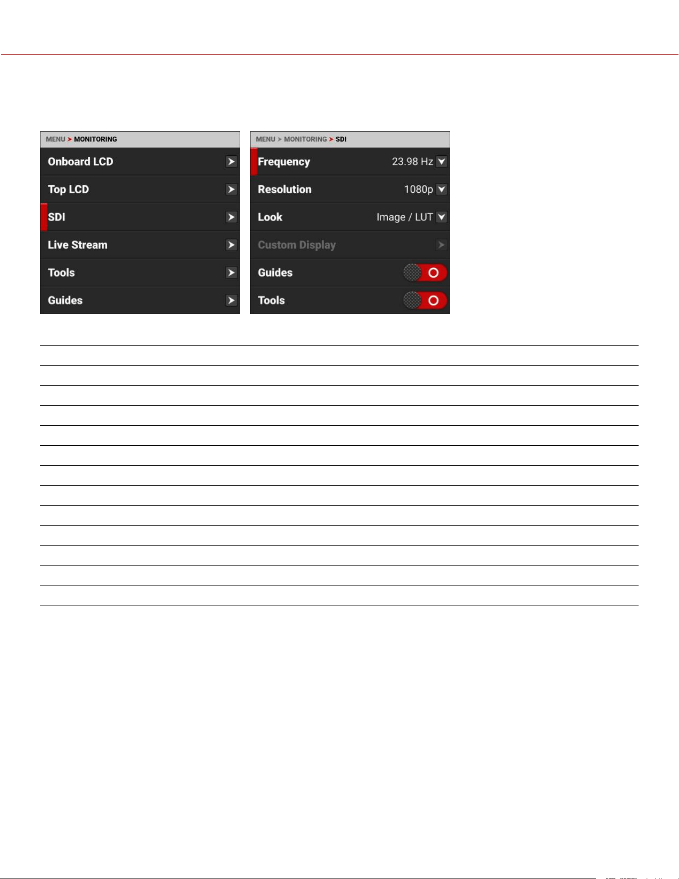
SDI
Use SDI to configure the SDI port settings.
The SDI port settings you can configure include:
ITEMS DETAILS
Frequency Select the SDI port frequency
Resolution Select the SDI port resolution
Look Select the Image / LUT, RWG, Log3G10, or a Custom Display image preview
Custom Display Configure the Custom Display settings when enabled
Guides Enable or disable the monitor guides
Tools Enable or disable the monitor tools
Magnify Enable or disable monitor magnification
Magnify Position (Global) Select the magnification area position
Overlay Enable or disable the monitor overlay
Overlay Mode Select the overlay type
Overlay Opacity Select the opacity of the overlay
Flip / Mirror Flip and mirror the image output to the monitor
WARNING: Under certain circumstances, it is possible for an SDI connector to incur damage when connected to an
accessory and powered without using shielded cables. RED recommends only using high quality, shielded BNC cables
that are rated for 12G-SDI signals and only using shielded power cables for powering SDI accessories.
Make sure power is connected to the SDI accessory at all times before you connect the BNC to the camera.
Ungrounded power from SDI accessories can damage the camera’s SDI port. To avoid this possible damage, attach the
power source to the accessory before attaching it to the BNC cable. When using RED Approved Third Party battery
plates, unplug the BNC cable prior to hot swapping.
When possible, avoid using P-Tap (also known as D-Tap) cables to power accessories. To avoid damage when using P-
Tap/D-Tap, it’s imperative that the connect/disconnect sequence (below) is followed precisely.
COPYRIGHT © 2023 RED.COM, LLC 955-0218, REV A | 96
KOMODO-X
®
OPERATION GUIDE
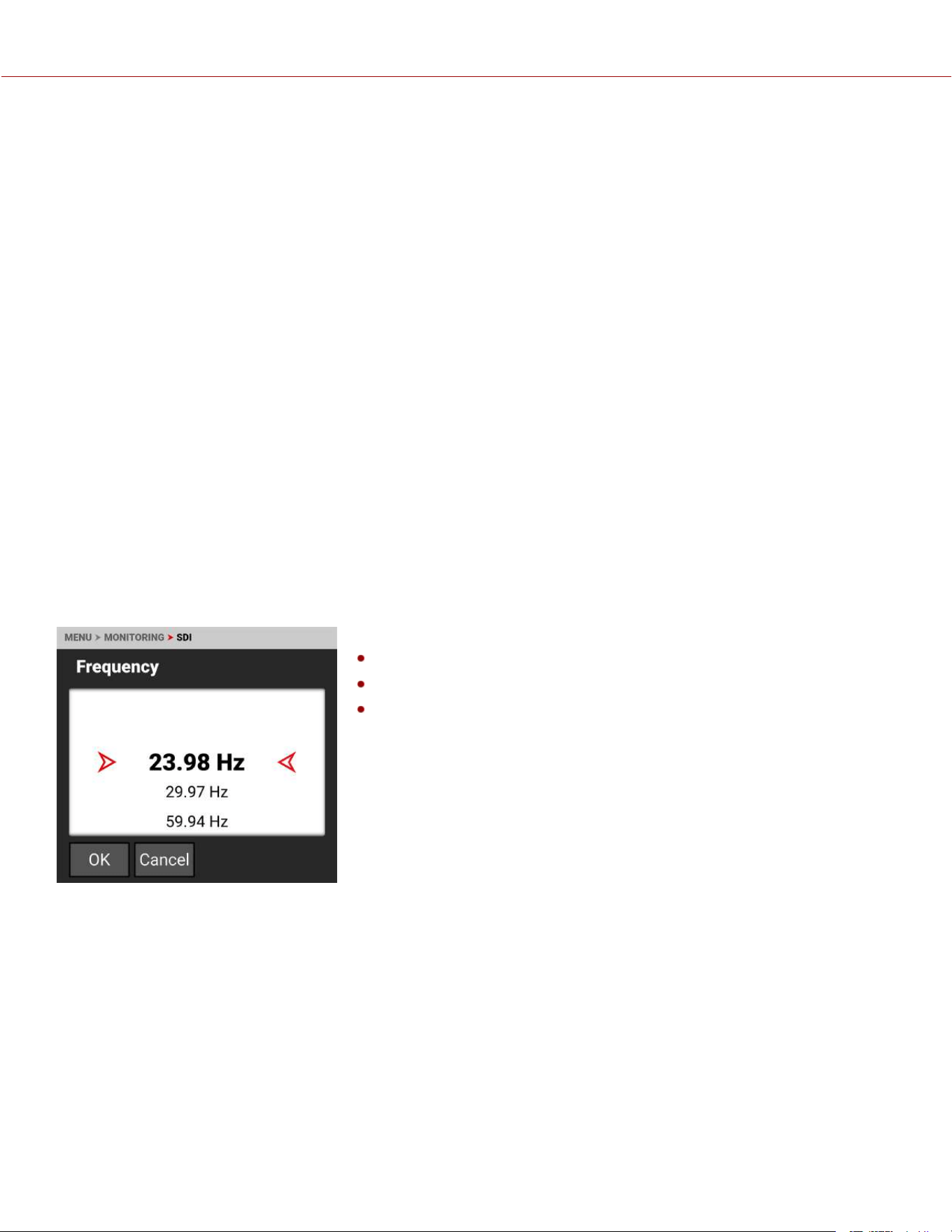
BNC ATTACHMENT INSTRUCTIONS
When attaching SDI accessories:
1. Connect a power source to the SDI accessory; power on the SDI accessory.
2. Ensure a power source is connected to the camera. This ensures both are grounded prior to connecting the BNC.
The camera's power state does not have an impact on SDI attachment sequence.
3. Connect the BNC cable to the accessory, then to the camera.
When detaching an accessory mounted to an SDI output, ensure that you remove the BNC connection to the camera
before removing power to the SDI device:
1. Shutdown the SDI accessory.
2. Disconnect the BNC cable from the camera.
3. Disconnect the power source from the SDI accessory.
When you need to swap out a battery on an accessory mounted to the camera’s SDI port, you must:
1. Shutdown the SDI accessory.
2. Disconnect the BNC cable from the camera.
3. Replace the battery on the SDI accessory.
4. Connect the BNC cable to the camera.
5. Power on the SDI accessory.
For more information, refer to Preventing Damage to SDI Outputs.
FREQUENCY
Use Frequency to select one of the following SDI port frequency settings:
23.98 Hz (default)
29.97 Hz
59.94 Hz
COPYRIGHT © 2023 RED.COM, LLC 955-0218, REV A | 97
KOMODO-X
®
OPERATION GUIDE
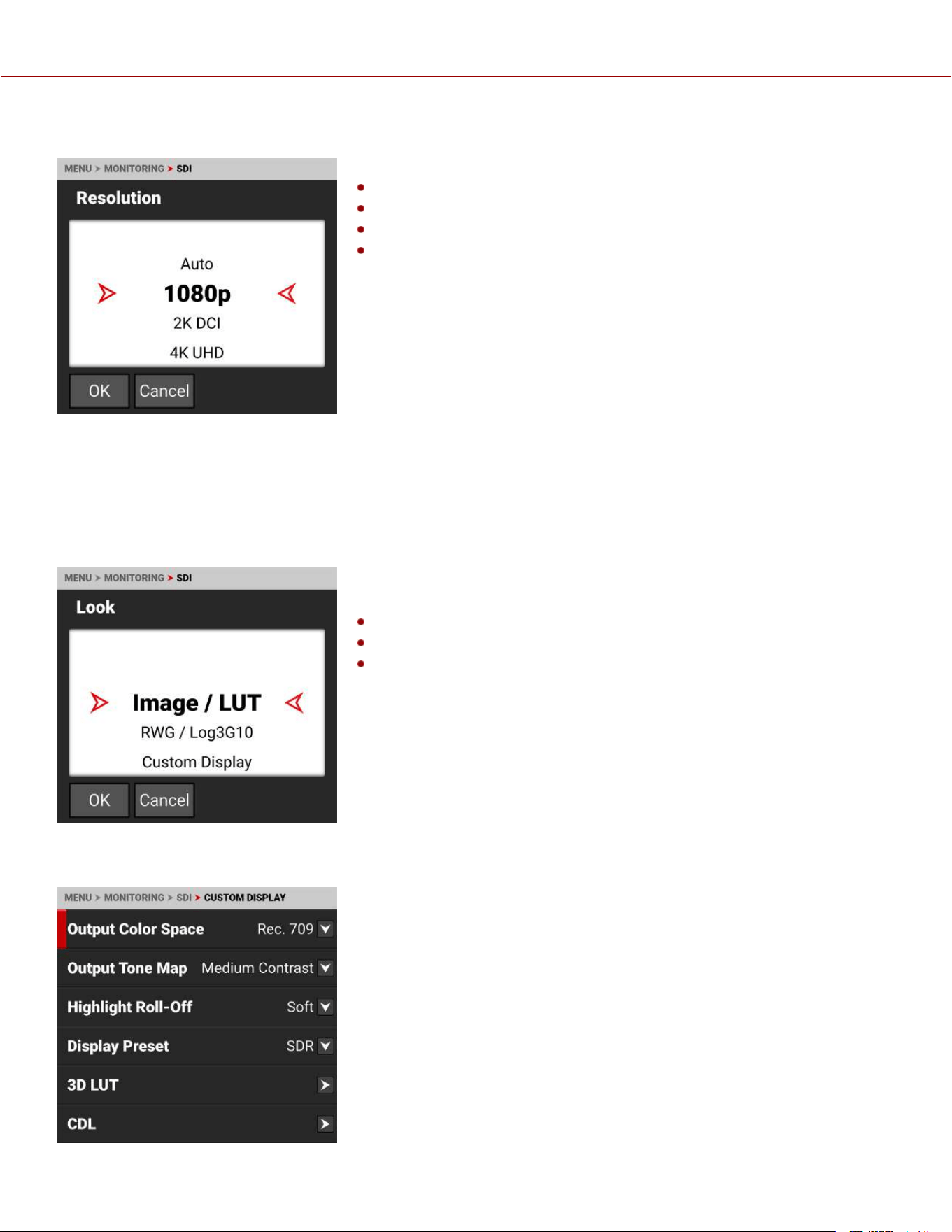
RESOLUTION
Use resolution to select one of the following SDI port resolution settings:
1080p (default)
2K DCI
4K UHD
4K DCI
The resolution selected here controls the SDI output resolution of the
preview page.
SCALING PREVIEW
When monitoring in 1080p or 4K UHD while capturing in a 17:9 format, the entire 17:9 image will be down-scaled to the
16:9 aspect ratio of 1080p or 4K UHD. Small black bars will only appear on the top and bottom of the frame in the
monitor path and not on the recorded image.
LOOK
You can select the look of the image preview signal sent to the SDI port.
The selections include:
Image / LUT (default)
REDWideGamutRGB / Log3G10
Custom Display (enables the Custom Display menu)
CUSTOM DISPLAY
Use Custom Display (enabled from the Look menu) to select the SDI's
isolated look settings.
Refer to Image / LUT Menu for more information about the specific look
settings and menus.
COPYRIGHT © 2023 RED.COM, LLC 955-0218, REV A | 98
KOMODO-X
®
OPERATION GUIDE
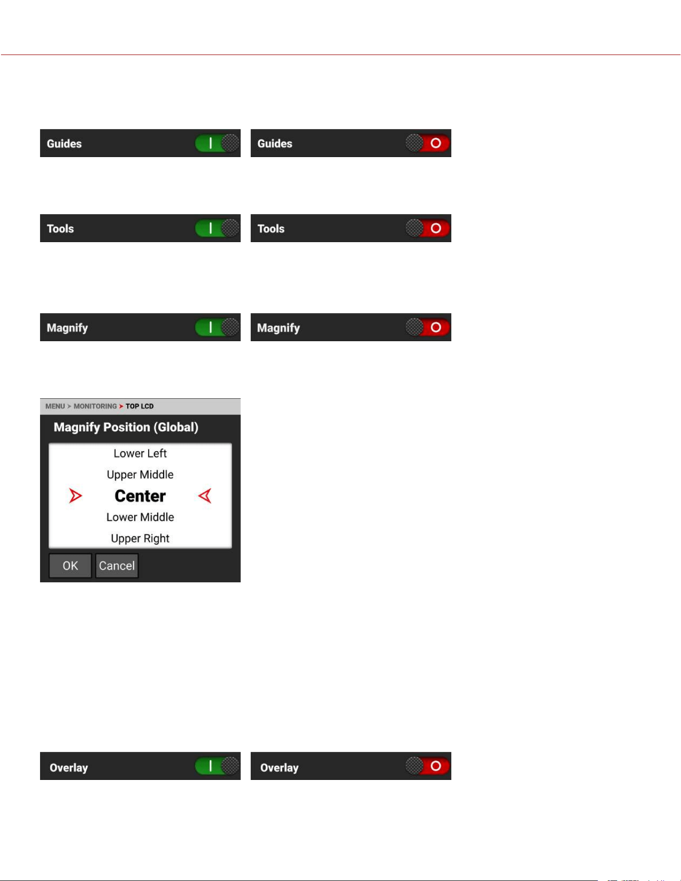
GUIDES
Use Guides to enable or disable (default) the viewing of guides. Tap the switch to toggle between enabled and disabled.
TOOLS
Use Tools to enable or disable (default) the viewing of tools. Tap the switch to toggle between enabled and disabled.
MAGNIFY
Use Magnify to enable or disable (default) monitor magnification. Tap the switch to toggle between enabled and
disabled.
MAGNIFY POSITION (GLOBAL)
Use Magnify Position (Global) to select the position of the magnified area for all magnification.
Use Magnify Position to globally select the area of the image you want to magnify.
The selections include:
• Left • Upper Middle • Upper Right
• Upper Left • Center (default) • Lower Right
• Lower Left • Lower Middle • Right
OVERLAY
Use Overlay to enable (default) or disable the viewing of the overlay. Tap the switch to toggle between enabled and
disabled.
COPYRIGHT © 2023 RED.COM, LLC 955-0218, REV A | 99
KOMODO-X
®
OPERATION GUIDE
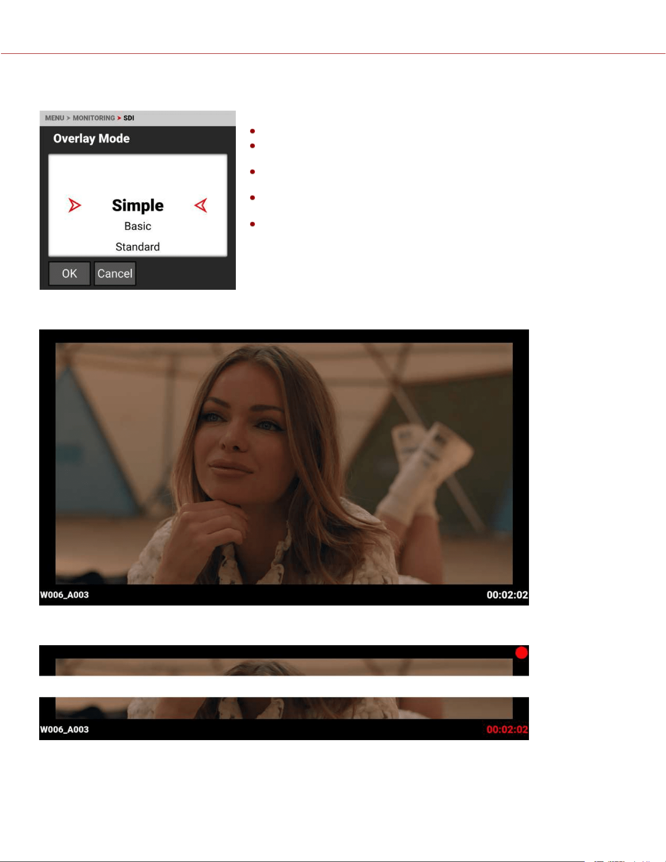
OVERLAY MODE
Use Overlay Mode to select one of the following SDI port overlay modes:
Simple - Minimal image information is displayed (refer to Simple Mode)
Basic - Simple plus time sensitive media and battery information (refer to
Basic Mode)
Standard - Industry standard image and camera details are displayed
(refer to Standard Mode)
Advanced - Standard plus exposure and audio meters (refer to Advanced
Mode)
Technical - Advanced plus lens focus distance and monitor look status
(refer to Technical Mode)
SIMPLE MODE
Simple mode displays the clip name and the current Timecode. When the camera is recording, the Timecode turns red,
and a red dot appears in the top right corner.
COPYRIGHT © 2023 RED.COM, LLC 955-0218, REV A | 100
KOMODO-X
®
OPERATION GUIDE
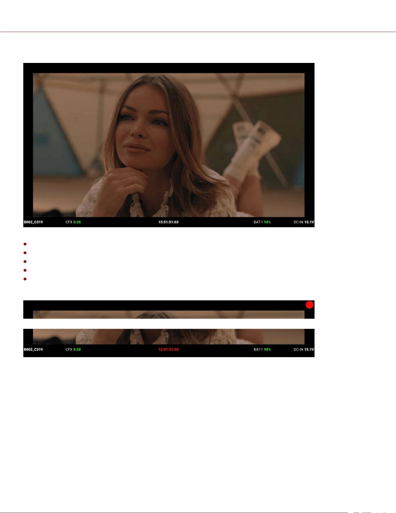
BASIC MODE
Basic mode displays the following:
Clip Name
CFexpress Time Remaining (at the current settings)
Timecode
Battery percentage remaining (at the current settings)
DC-IN
When the camera is recording, the Timecode turns red, and a red dot appears in the top right corner.
COPYRIGHT © 2023 RED.COM, LLC 955-0218, REV A | 101
KOMODO-X
®
OPERATION GUIDE
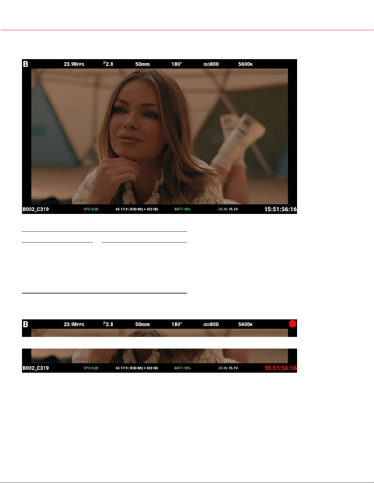
STANDARD MODE
Standard mode displays the following:
TOP BOTTOM
• Camera ID
• Recording Frame Rate
• f-Stop
• Focus Length
• Shutter Angle
• ISO
• White Balance
• Clip Name
• CFexpress Time Remaining
• Format, File Type, Rate
• Battery
• DC-IN
• Timecode
Lens items such as Focal Length and f-Stop will adaptively display depending on whether the lens data is available.
When the camera is recording, the Timecode turns red, and a red dot appears in the top right corner.
COPYRIGHT © 2023 RED.COM, LLC 955-0218, REV A | 102
KOMODO-X
®
OPERATION GUIDE
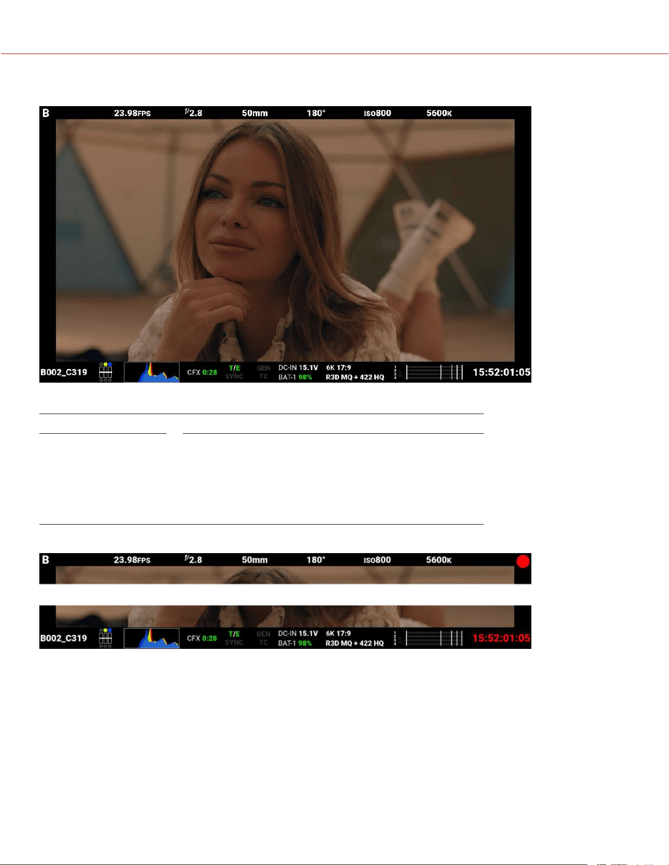
ADVANCED MODE
Advanced mode displays the following:
TOP BOTTOM
• Camera Number
• Recording Frame Rate
• f-Stop
• Focus Length
• Shutter Angle
• ISO
• White Balance
• Clip Name
• Exposure Meter
• Histogram
• CFexpress Time Remaining
• Temperature / Exposure
Calibration
• Timecode, Genlock, Synch
• DC-In, Battery
• Format, File Type, Rate
• VU Meter
• Timecode
When the camera is recording, the Timecode turns red, and a red dot appears in the top right corner.
COPYRIGHT © 2023 RED.COM, LLC 955-0218, REV A | 103
KOMODO-X
®
OPERATION GUIDE
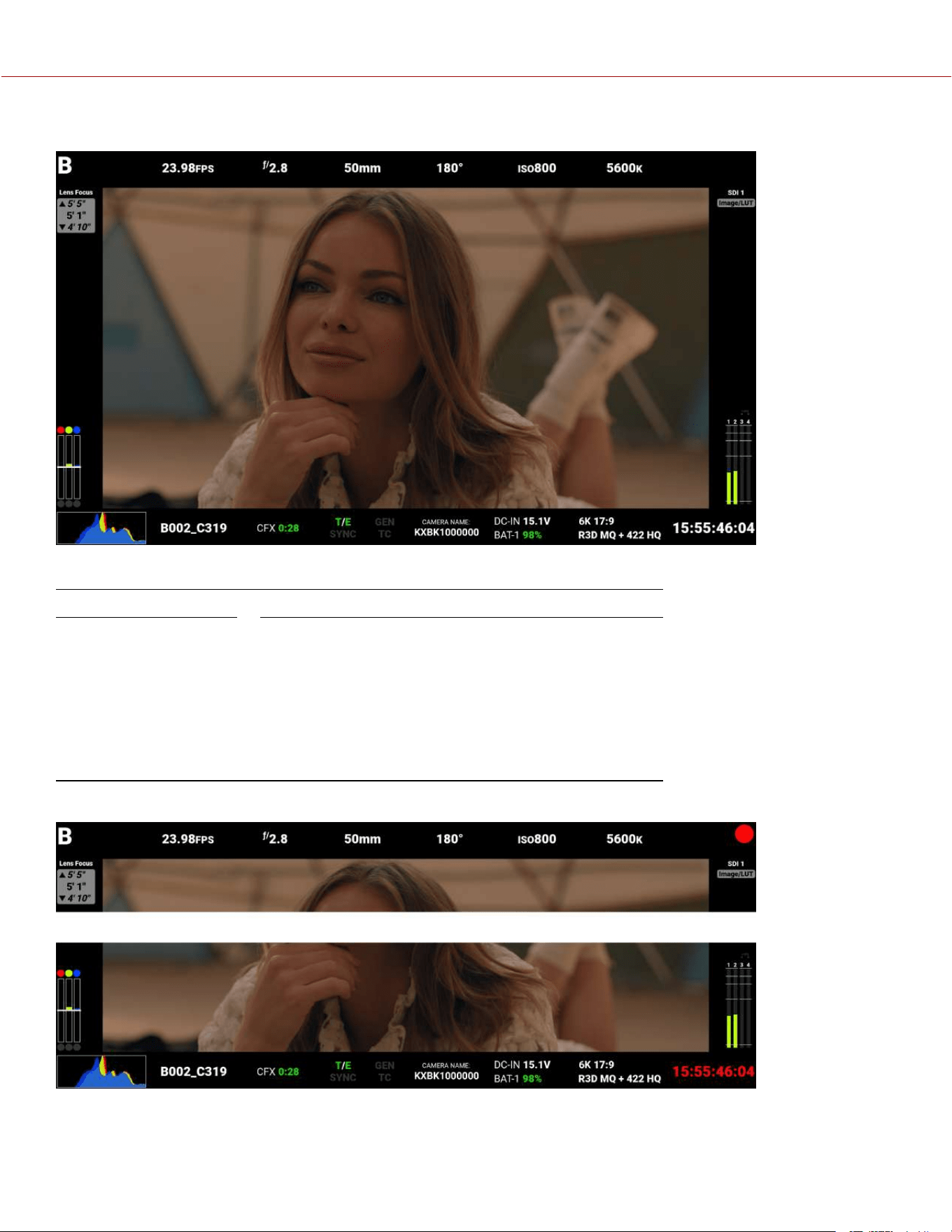
TECHNICAL MODE
Technical mode displays the following:
TOP BOTTOM
• Camera ID
• Recording Frame Rate
• f-Stop
• Focus Length
• Shutter Angle
• ISO
• White Balance
• SDI Look
• Exposure Meter
• Histogram
• Clip Name
• CFexpress Time Remaining
• Temperature / Exposure
Calibration
• Timecode, Genlock, Synch
• Camera Name
• DC-In, Battery
• Format, File Type, Rate
• Timecode
• VU Meter
When the camera is recording, the Timecode turns red, and a red dot appears in the top right corner.
COPYRIGHT © 2023 RED.COM, LLC 955-0218, REV A | 104
KOMODO-X
®
OPERATION GUIDE
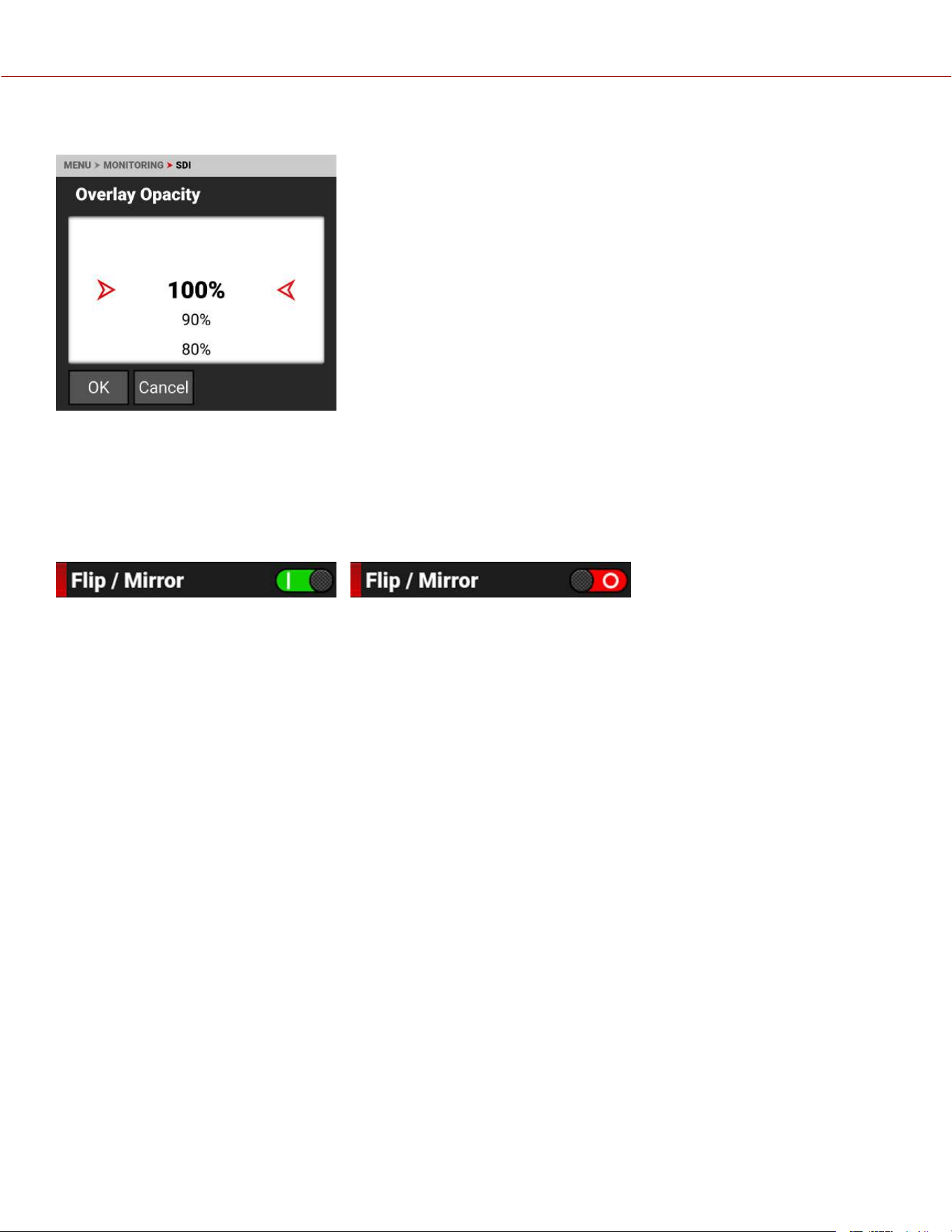
OVERLAY OPACITY
Use Overlay Opacity to select the percentage of opacity you want the overlay to display on the SDI output.
The opacity values the camera can display are between 100% and 0%.
FLIP / MIRROR
Use Flip / Mirror to enable or disable the flipped mirrored orientation of the SDI output. Press SEL to toggle between
enabled and disabled (default).
SDI PORT DESCRIPTION
The Serial Digital Interface (SDI) port allows the camera to deliver 12 Gbps of image bandwidth with greater resolution,
frame rates, and color fidelity. This single BNC cable solution makes it ideal for the 4Kp60 format. The output signal bit
depth is 10-bit 4:2:2.
WARNING: Under certain circumstances, it is possible for an SDI connector to incur damage when connected to an
accessory and powered without using shielded cables. RED recommends only using high quality, shielded BNC cables
that are rated for 12G-SDI signals and only using shielded power cables for powering SDI accessories.
Make sure power is connected to the SDI accessory at all times before you connect the BNC to the camera.
Ungrounded power from SDI accessories can damage the camera’s SDI port. To avoid this possible damage, attach the
power source to the accessory before attaching it to the BNC cable. When using RED Approved Third Party battery
plates, unplug the BNC cable prior to hot swapping.
When possible, avoid using P-Tap (also known as D-Tap) cables to power accessories. To avoid damage when using P-
Tap/D-Tap, it’s imperative that the connect/disconnect sequence (below) is followed precisely.
BNC ATTACHMENT INSTRUCTIONS
When attaching SDI accessories:
1. Connect a power source to the SDI accessory; power on the SDI accessory.
2. Ensure a power source is connected to the camera. This ensures both are grounded prior to connecting the BNC.
The camera's power state does not have an impact on SDI attachment sequence.
3. Connect the BNC cable to the accessory, then to the camera.
COPYRIGHT © 2023 RED.COM, LLC 955-0218, REV A | 105
KOMODO-X
®
OPERATION GUIDE
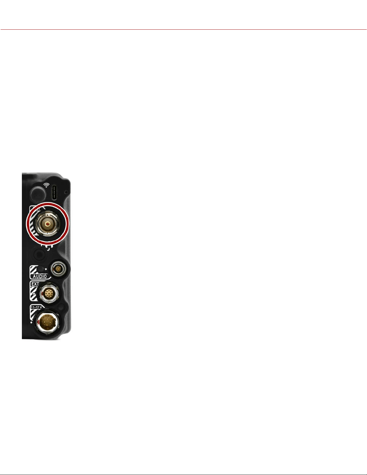
When detaching an accessory mounted to an SDI output, ensure that you remove the BNC connection to the camera
before removing power to the SDI device:
1. Shutdown the SDI accessory.
2. Disconnect the BNC cable from the camera.
3. Disconnect the power source from the SDI accessory.
When you need to swap out a battery on an accessory mounted to the camera’s SDI port, you must:
1. Shutdown the SDI accessory.
2. Disconnect the BNC cable from the camera.
3. Replace the battery on the SDI accessory.
4. Connect the BNC cable to the camera.
5. Power on the SDI accessory.
For more information, refer to Preventing Damage to SDI Outputs.
For more information about the SDI standard, refer to the SMPTE (Society of Motion Picture
and Television Engineers) standard SMPTE ST-2082.
COPYRIGHT © 2023 RED.COM, LLC 955-0218, REV A | 106
KOMODO-X
®
OPERATION GUIDE
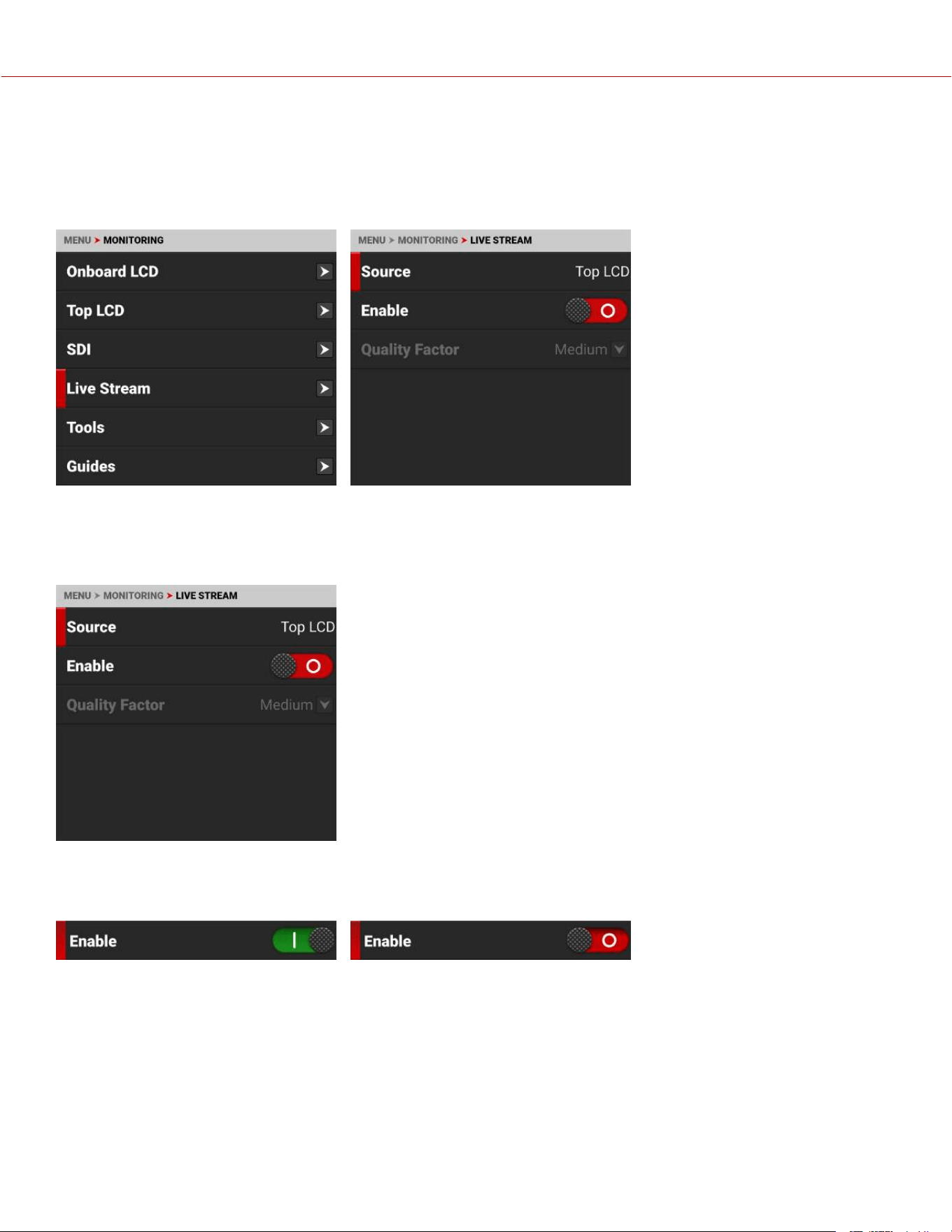
LIVE STREAM
Use Live Stream to enable or disable live streaming over Wi-Fi. The Live Stream image is controlled by the LCD
monitoring tools (the Guides are not displayed). Refer to Monitoring Tools for more information.
NOTE: When live streaming, select 5 GHz as the Wi-Fi band (refer to Ad-Hoc).
SOURCE
Source displays the source of the Live Stream image. Live stream displays the looks, tools, and magnification enabled
for that source.
ENABLE
Use Enable to enable or disable (default) the Live Stream feature.
COPYRIGHT © 2023 RED.COM, LLC 955-0218, REV A | 107
KOMODO-X
®
OPERATION GUIDE
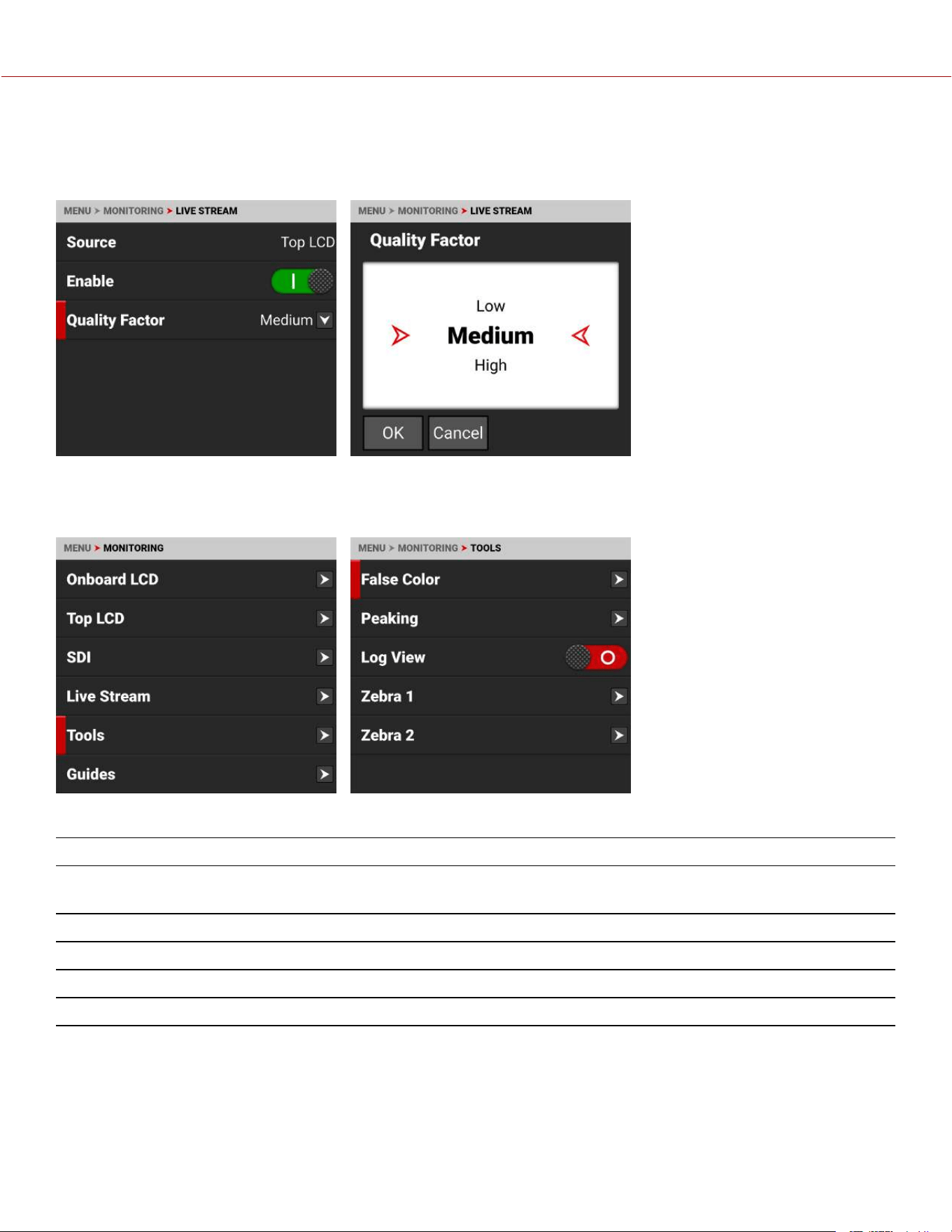
QUALITY FACTOR
Use Quality Factor, when Live Streaming is enabled, to control the video quality the camera's output stream. Lower
quality can stream over a longer distance.
TOOLS
The Tools menu provides access to the monitoring tools you use to monitor image exposure and focus.
The monitoring tools that you can use include:
ITEMS DETAILS
False
Color
Enable and configure the False Color Exposure Mode, False Color Video Mode, and the False Color Video
Mode
Peaking Enable and configure focus indicating modes
Log View Enable or disable (default) Log View
Zebra 1 Enable and configure Zebra 1 settings
Zebra 2 Enable and configure Zebra 2 settings
COPYRIGHT © 2023 RED.COM, LLC 955-0218, REV A | 108
KOMODO-X
®
OPERATION GUIDE
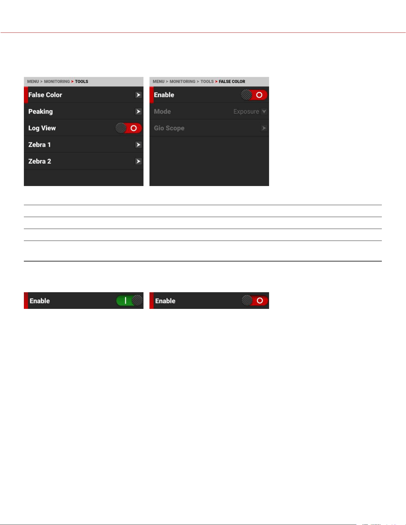
FALSE COLOR
Use False Color to configure the False Color tool settings.
The False Color tool settings you can configure include:
ITEMS DETAILS
Enable Enable or disable the False Color tool modes
False Color Mode Select the False Color tool mode
False Color Gio Scope
Mode
Identify 16+ increments within the dynamic range of the RAW sensor image.
ENABLE
Use Enable to enable or disable the False Color tool.
COPYRIGHT © 2023 RED.COM, LLC 955-0218, REV A | 109
KOMODO-X
®
OPERATION GUIDE
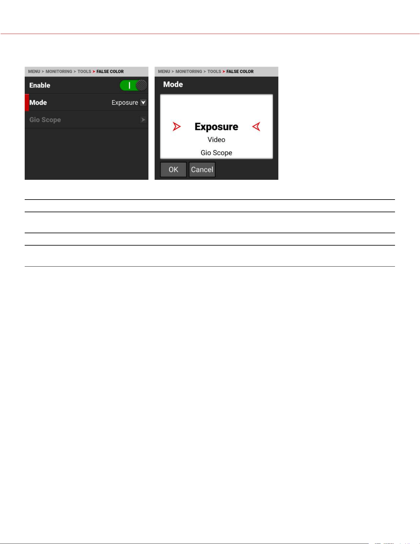
FALSE COLOR MODE
False Color Modes include:
ITEMS DETAILS
False Color Exposure Mode Use false colors to determine an optimal balance between overexposure and
underexposure.
False Color Video Mode Access scene exposure in varying light without relying on the LCD image brightness.
False Color Gio Scope
Mode
Identify 16+ increments within the dynamic range of the RAW sensor image.
NOTE: False Color modes display on video recorded through SDI to an external recorder when the Tools are enabled in
the Monitor menu. When recording through SDI, use False Color modes only to help determine scene exposure
settings, and then disable the mode before recording.
FALSE COLOR EXPOSURE MODE
When this monitoring False Color mode is activated, most of the tonal range will appear in monochrome.
The Exposure Mode is able to indicate exactly where middle gray is falling, and indicate which highlights or shadows
are problematic in the logarithmic representation of the image. Exposure mode is judging the exposure after ISO and
White Balance adjustments are made, and before any sort of LUT or transform is applied to the Log3G10 image.
RED FALSE COLOR OVERLAY
When the False Color Mode overlays the color red within the subject of interest, or anywhere except bright lights and
direct reflections, then the image is likely overexposed. When the False Color Mode does not overlay the color red on
the image, then the exposure is likely okay for the selected ISO.
PURPLE FALSE COLOR OVERLAY
When the False Color Mode overlays the color purple on key image detail that is not located in the shadows, then the
scene is likely underexposed. When the False Color Mode does not overlay the color purple on the image, then the
exposure is likely okay for the selected ISO.
For more information, refer to Exposure in the How To section.
COPYRIGHT © 2023 RED.COM, LLC 955-0218, REV A | 110
KOMODO-X
®
OPERATION GUIDE
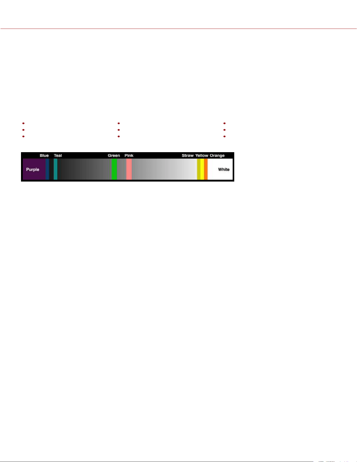
FALSE COLOR VIDEO MODE
NOTE: For best results, Video Mode should be viewed at or above ISO 800.
Video Mode displays a color overlay that indicates the video level of the RGB monitor path (calibrated to the SMPTE
test signal).
The colors used are based on the RGB levels of the video out signal (that is, the “cooked” look, and not RAW data). The
camera's RGB settings can change the appearance of the Video Mode colors.
The Video Mode colors represent the following IRE values (at all other values, the desaturated image represents the
luminance value of the ISO adjusted image):
Purple: IRE 0–4
Blue: IRE 5
Teal: IRE 10–12
Green: IRE 41–48
Pink: IRE 61–70
Straw: IRE 92–93
Yellow: IRE 94–95
Orange: IRE 96–98
Red: IRE 99–100
For more information, refer to Exposure in the How To section.
Green is where you will want 18% gray, Pink is typically the brightness of Caucasian skin tones, Straw, Yellow, and
Orange are strong highlights and increasingly closer to white, Teal is deep shadows and Blue is on the verge of
becoming untextured black. In general, Pink and Green are most helpful when calibrating based on a known reference,
whereas the other colors indicate the extremes of a tonal range.
A potential disadvantage of False Color Video mode is that all the false colors can distract from the underlying preview.
Many prefer to use this mode only during initial set-up, and then they use False Color Exposure Mode under a wider
range of scenarios.
IN PRACTICE
In False Color Exposure Mode, use the purple and red indicators to adjust your lighting or lens aperture. Use this
strategy to achieve an optimal balance between clipping from overexposure and image noise from underexposure. With
most scenes, you can often have a surprising range of exposure latitude before excessive red or purple indicators begin
to appear.
If necessary, use False Color Video mode or Zebra Modes to fine-tune how the scene will appear over SDI, or use it to
adjust your suggested look when sending footage for post-production.
The Zebra and Video modes are also an objective way to assess the scene exposure under varying ambient light
without relying on the LCD image to evaluate brightness.
FALSE COLOR GIO SCOPE MODE
Gio Scope mode displays a color overlay on top of a desaturated RAW sensor image, identifying 16 increments within
the dynamic range of the sensor. The RGB settings (color temperature, ISO, LUT, etc.) are not used by this mode.
Each number (1 to 16) indicates a different increment of dynamic range. Number 16 represents the top increment, and is
broken up into 1/8th sub-increments to show highlight roll-off. Each 1/8th increment is represented by a different shade
of red, ranging from light red (less light) to dark red (most light, clipping).
COPYRIGHT © 2023 RED.COM, LLC 955-0218, REV A | 111
KOMODO-X
®
OPERATION GUIDE
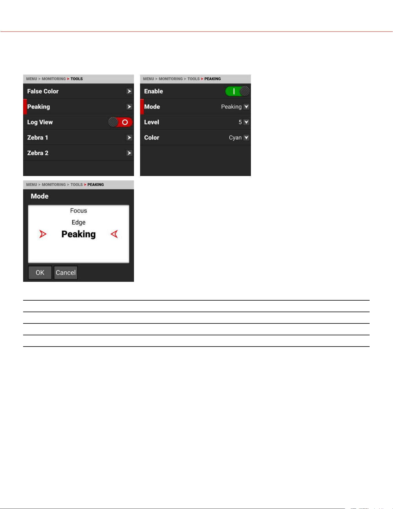
PEAKING
The Peaking tools display contrast, outlines, or colors to assist with focusing.
The Peaking modes you can use include:
ITEMS DETAILS
Focus Use enhanced contrast and edges for focusing
Edge Show outlines of focused objects
Peaking Select a colored overlay to indicate objects in focus
FOCUS PEAKING MODE
Focus Peaking mode emphasizes contrast and edges in the image without changing the brightness or the image
content. This mode makes it easier to judge focus. Adjust the zoom and focus to easily see which objects are coming
into focus.
COPYRIGHT © 2023 RED.COM, LLC 955-0218, REV A | 112
KOMODO-X
®
OPERATION GUIDE
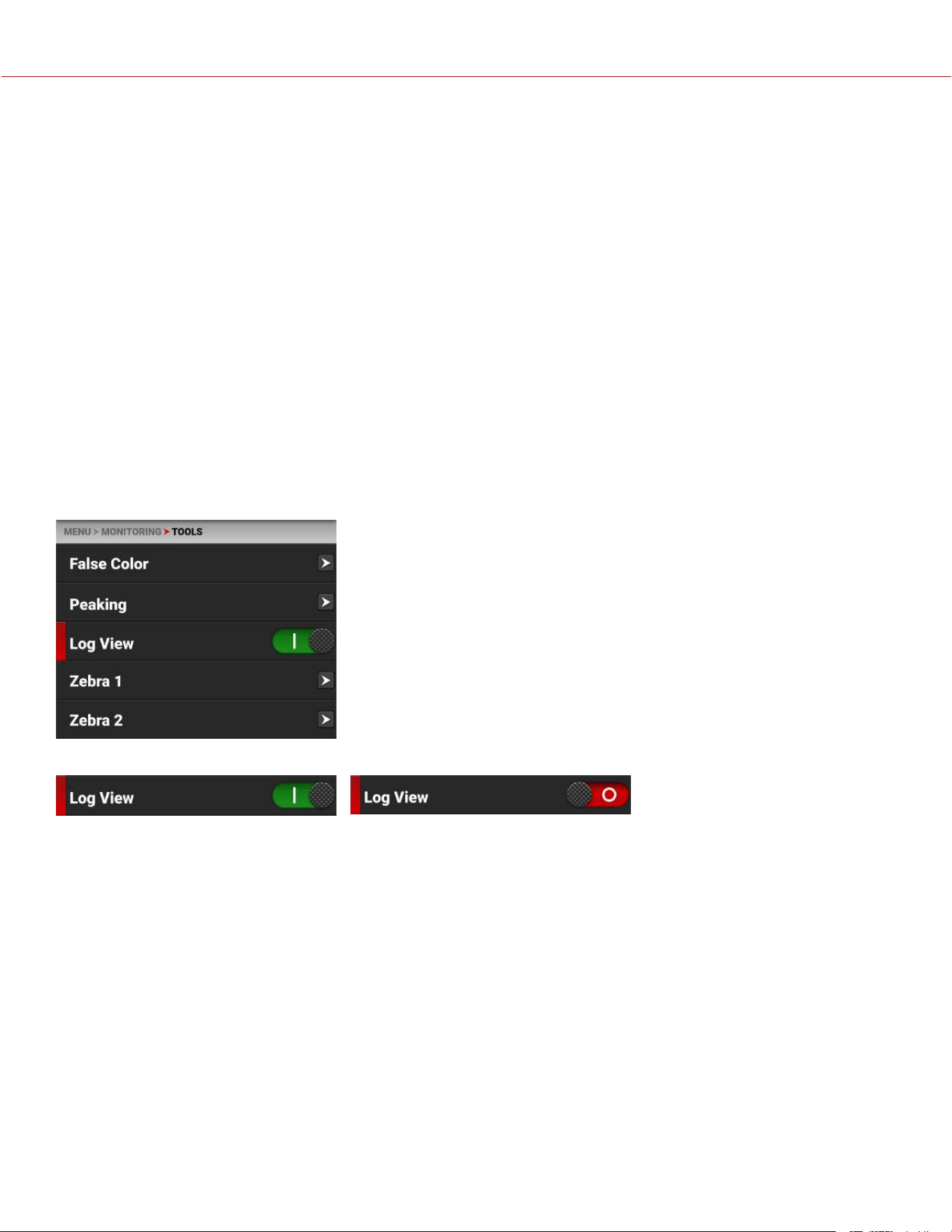
EDGE PEAKING MODE
When you enable Edge Peaking mode, the display shows the edges or outlines of objects that are in focus.
PEAKING PEAKING MODE
The Peaking Peaking mode displays a color overlay on top of in-focus edges. Select a Level of 1 to 10 (weak to strong)
for the intensity of the color overlay. The RGB settings can change the appearance of the selected color overlay.
The Peaking Peaking mode indicator is applied after the image is scaled to a monitor, making the indicators appear
differently on various monitors.
For more information about Peaking, refer to Focus in the How To section.
LOG VIEW
Use Log View to display camera images in REDWideGamutRGB and Log3G10 for the ISO, Exposure Adjust, Color
Temperature, and Tint settings. This allows you to quickly see ungraded footage that remains unaffected by creative
decisions such as the choice of 3D LUT or CDL.
Log View is passed through the SDI port when recording to an external recorder. You can view the Log image in
playback on the LCD and on the monitor. However, Log View is not recorded to the file recorded on the media card.
NOTE: Log View is only enabled on R3D files and not on ProRes files.
Use the toggle to switch from Enabled to Disabled:
COPYRIGHT © 2023 RED.COM, LLC 955-0218, REV A | 113
KOMODO-X
®
OPERATION GUIDE
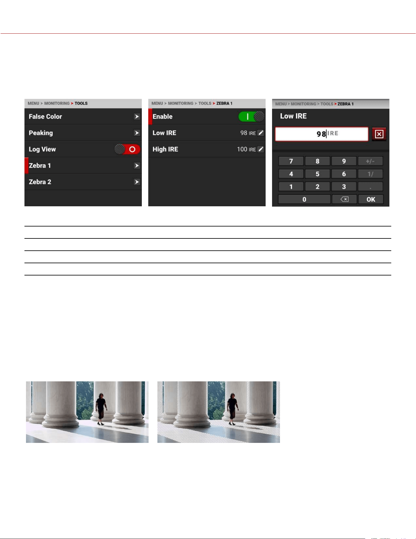
ZEBRA 1
Use Zebra 1 to display one set of diagonal stripes to indicate highlight exposure levels. For more information, refer to
Zebra Modes.
Zebra 1 is disabled by default.
The Zebra 1 mode includes:
ITEMS DETAILS
Enable Enables red zebra stripes to indicate highlight exposure
Low IRE Sets the lower threshold for the indicator
High IRE Sets the higher threshold for the indicator
ENABLE
The Enable toggle switch allows you to enable or disable the Zebra 1 stripes.
LOW IRE
Provides a keypad that allows you to set the low threshold for the Zebra stripe. The default setting is 98 IRE.
HIGH IRE
Provides a keypad that allows you to set the high threshold for the Zebra stripe. The default setting is 100 IRE.
NORMAL VIEW ZEBRA 1 VIEW
COPYRIGHT © 2023 RED.COM, LLC 955-0218, REV A | 114
KOMODO-X
®
OPERATION GUIDE
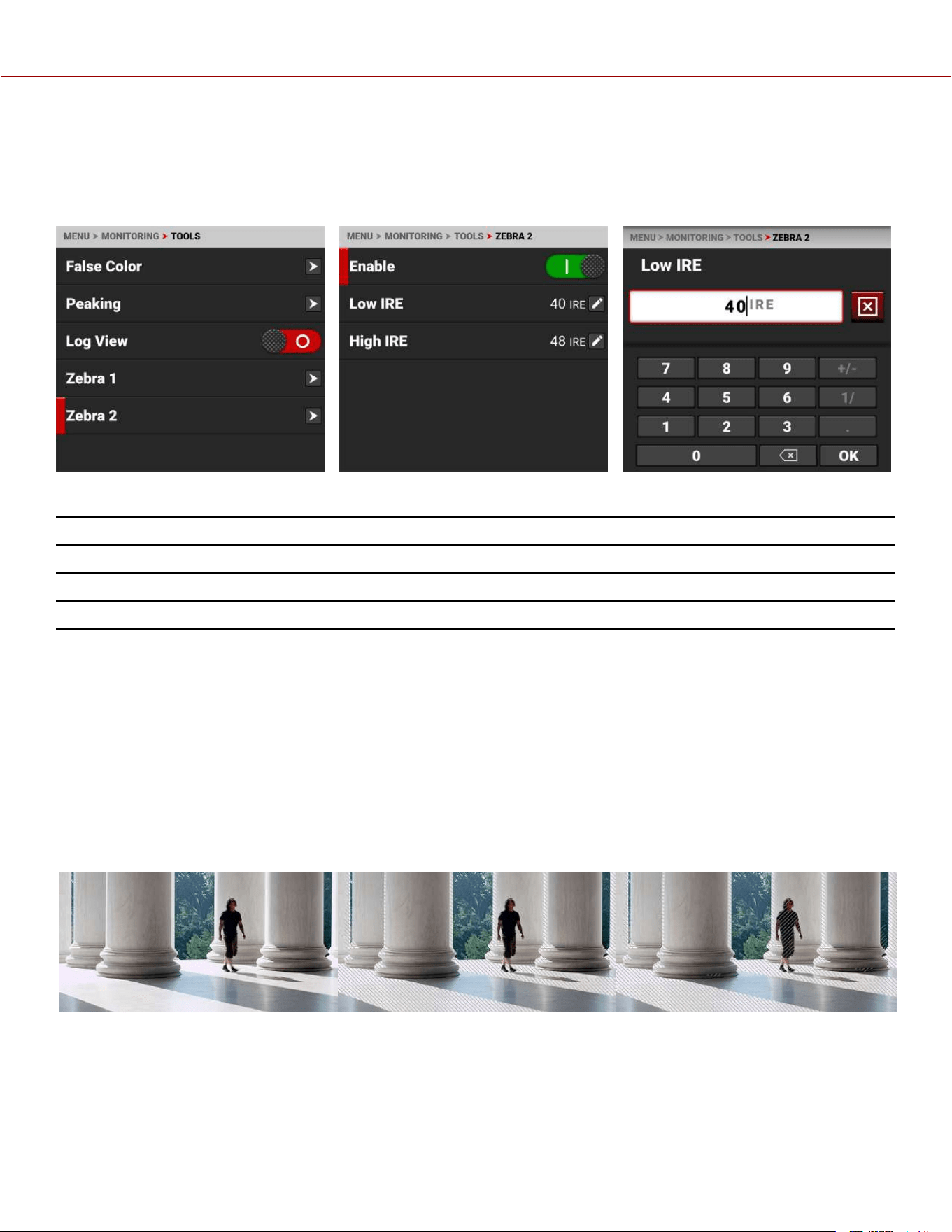
ZEBRA 2
Use Zebra 2 to display a second set of diagonal stripes to indicate mid-tone and shadow levels. For more information,
refer to Zebra Modes.
Zebra 2 is disabled by default.
The Zebra 2 mode includes:
ITEMS DETAILS
Enable Enables green zebra stripes to indicate mid-tone and shadow exposure
Low IRE Sets the lower threshold for the indicator
High IRE Sets the higher threshold for the indicator
ENABLE
The Enable toggle switch allows you to enable or disable the Zebra 2 stripes.
LOW IRE
Provides a keypad that allows you to set the low threshold for the Zebra stripe. The default setting is 40 IRE.
HIGH IRE
Provides a keypad that allows you to set the high threshold for the Zebra stripe. The default setting is 48 IRE.
NORMAL VIEW ZEBRA 1 VIEW ZEBRA 2 VIEW
COPYRIGHT © 2023 RED.COM, LLC 955-0218, REV A | 115
KOMODO-X
®
OPERATION GUIDE
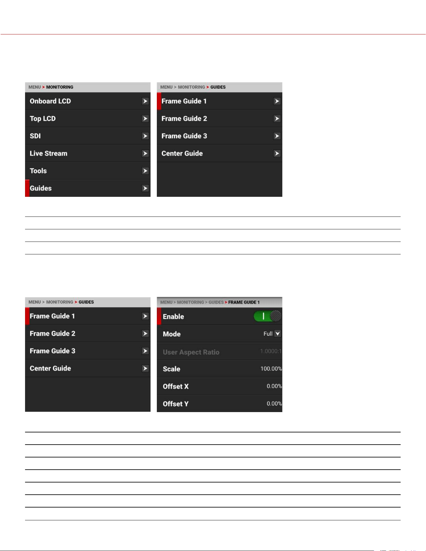
GUIDES
Use Guides to enable and configure the camera's monitoring guides.
The monitoring Guides that you can use include:
ITEMS DETAILS
Frame Guides Guides you can configure to aid in framing a shot
Center Guide A center cross hair or dot you can use to center your shot
FRAME GUIDES
Use Frame Guides to frame the scene using various shapes and sizes. You can configure up to 3 Frame Guides to
display on your monitor.
Configure the Frame Guides using the following:
ITEMS DETAILS
Enable Enables the Frame Guide
Mode Select aspect ratios, User, and Absolute modes
User Aspect Ratio Enabled by selecting User mode
Scale Percentage of the image the Frame Guide occupies
Offset X, Y Percentage of horizontal and vertical offset
Absolute X, Y, W, H Absolute mode - set the exact number of size and offset pixels
COPYRIGHT © 2023 RED.COM, LLC 955-0218, REV A | 116
KOMODO-X
®
OPERATION GUIDE
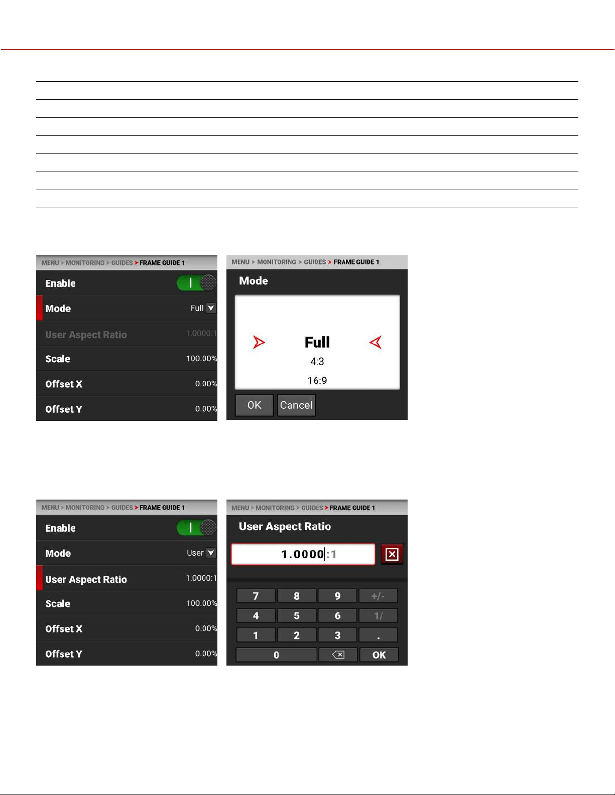
ITEMS DETAILS
Line Style Select the Frame Guide line type - solid, dashed or bracket
Line Color Select the Frame Guide line color
Line Opacity Select the Frame Guide line opacity percentage
Shade Outside Enables shading outside of the Frame Guide
Shade Color Select the shading color
Shade Opacity Select the shading opacity
MODE
Use Mode to select the Frame Guide mode you want to use to configure the frame guide.
The modes you can select include aspect ratios from Full to 2.4:1, User, and Absolute. The User and Absolute modes
enable settings that are specific to those modes.
USER ASPECT RATIO
This item is enabled when the User mode is selected.
Use the keypad to enter your desired aspect ratio.
COPYRIGHT © 2023 RED.COM, LLC 955-0218, REV A | 117
KOMODO-X
®
OPERATION GUIDE
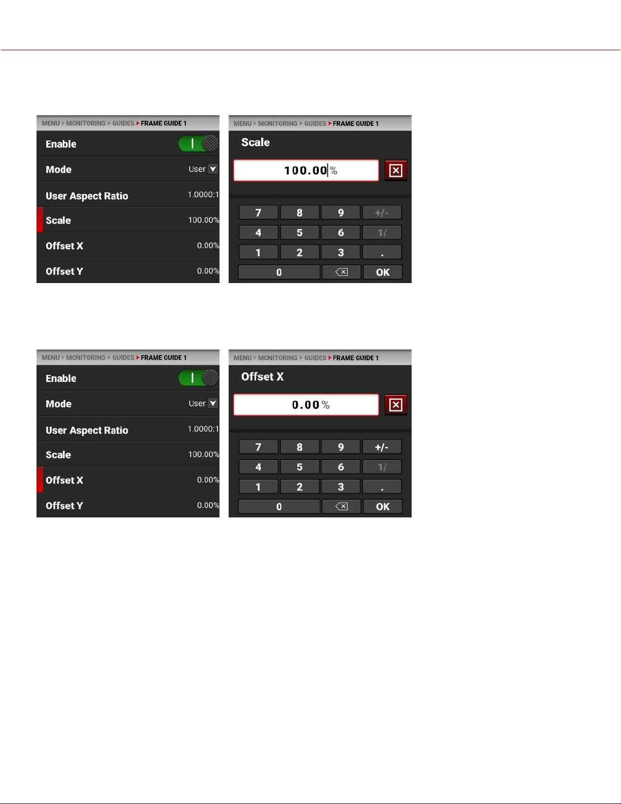
SCALE
Use scale to configure the percentage of the image area that the Frame Guide will frame.
Use the keypad to enter the percentage of the image the Frame Guide contains.
OFFSET X, Y
Use offset to configure the X and Y offset of the Frame Guide.
Use the keypad to enter the percentage of offset from center you want to apply to the Frame Guide.
COPYRIGHT © 2023 RED.COM, LLC 955-0218, REV A | 118
KOMODO-X
®
OPERATION GUIDE
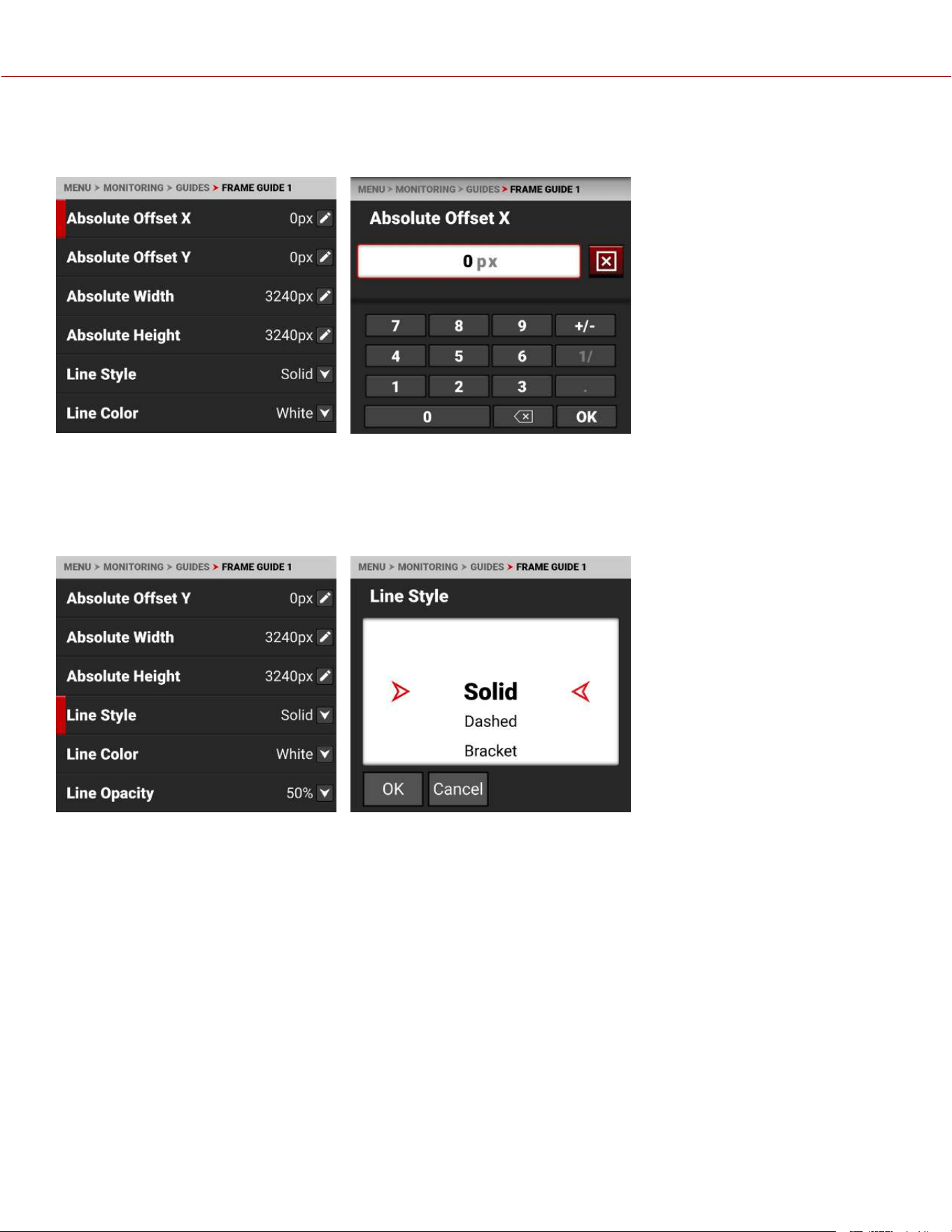
ABSOLUTE X, Y, W, H
Use the Absolute settings to configure the absolute dimensions and position of the Frame Guide.
Use the keypad to enter the number of pixels for X/Y offset and for the width and height of the Frame Guide. The
Absolute items are only enabled when you select Absolute Mode.
LINE STYLE
Use Line Style to select the type of line the Frame Guide uses.
Select Solid (default), Dashed, or Bracket for the Frame Guide line style.
COPYRIGHT © 2023 RED.COM, LLC 955-0218, REV A | 119
KOMODO-X
®
OPERATION GUIDE
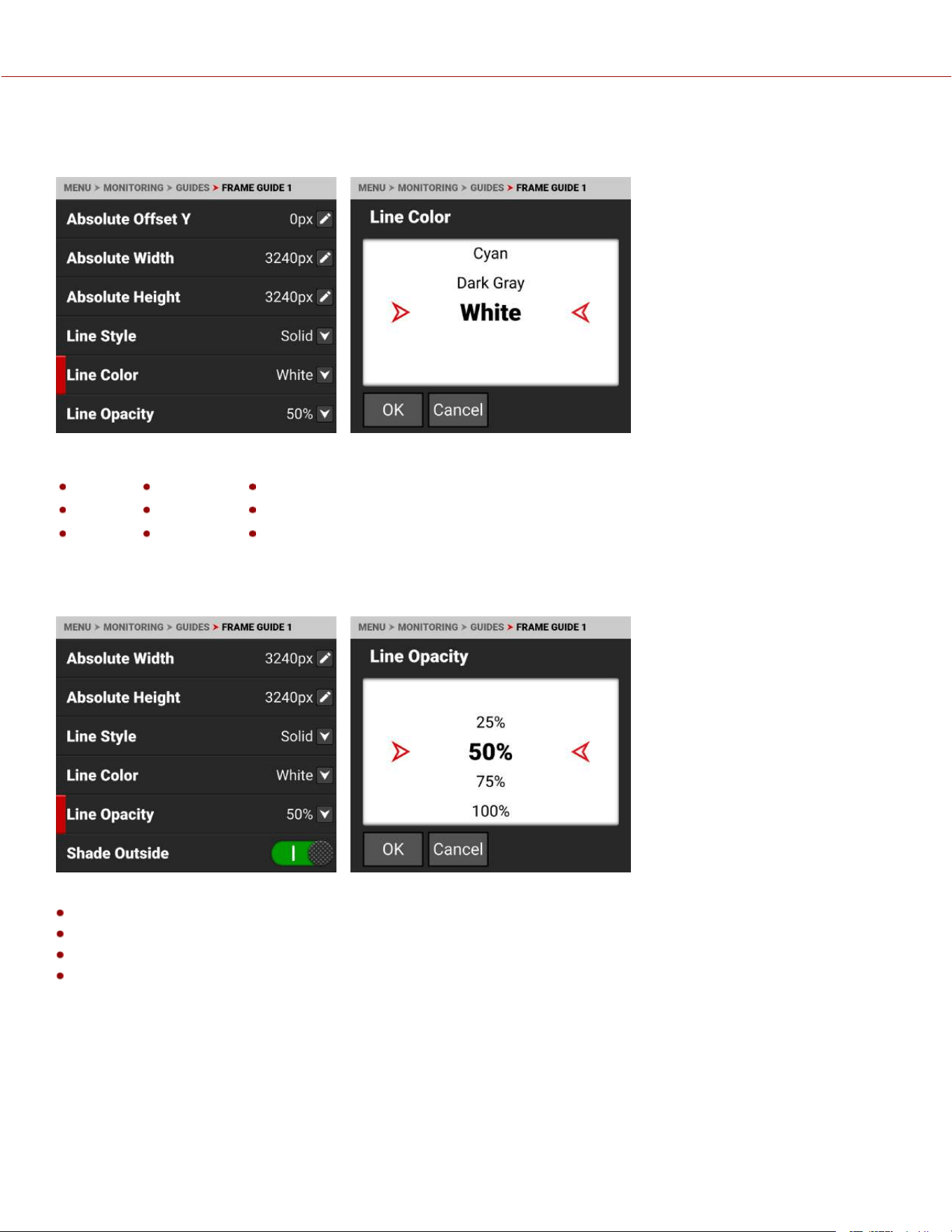
LINE COLOR
Use Line Color to select the color of the Frame Guide line.
Use Line Color to select one of the following colors for the Frame Guide line:
Black Green Cyan
Red Yellow Dark Gray
Blue Magenta White (default)
LINE OPACITY
Use Line Opacity to select how transparent the Frame Guide line appears.
Use Line Opacity to select the percentage of opacity for the Frame Guide line:
25%
50% (default)
75%
100%
COPYRIGHT © 2023 RED.COM, LLC 955-0218, REV A | 120
KOMODO-X
®
OPERATION GUIDE
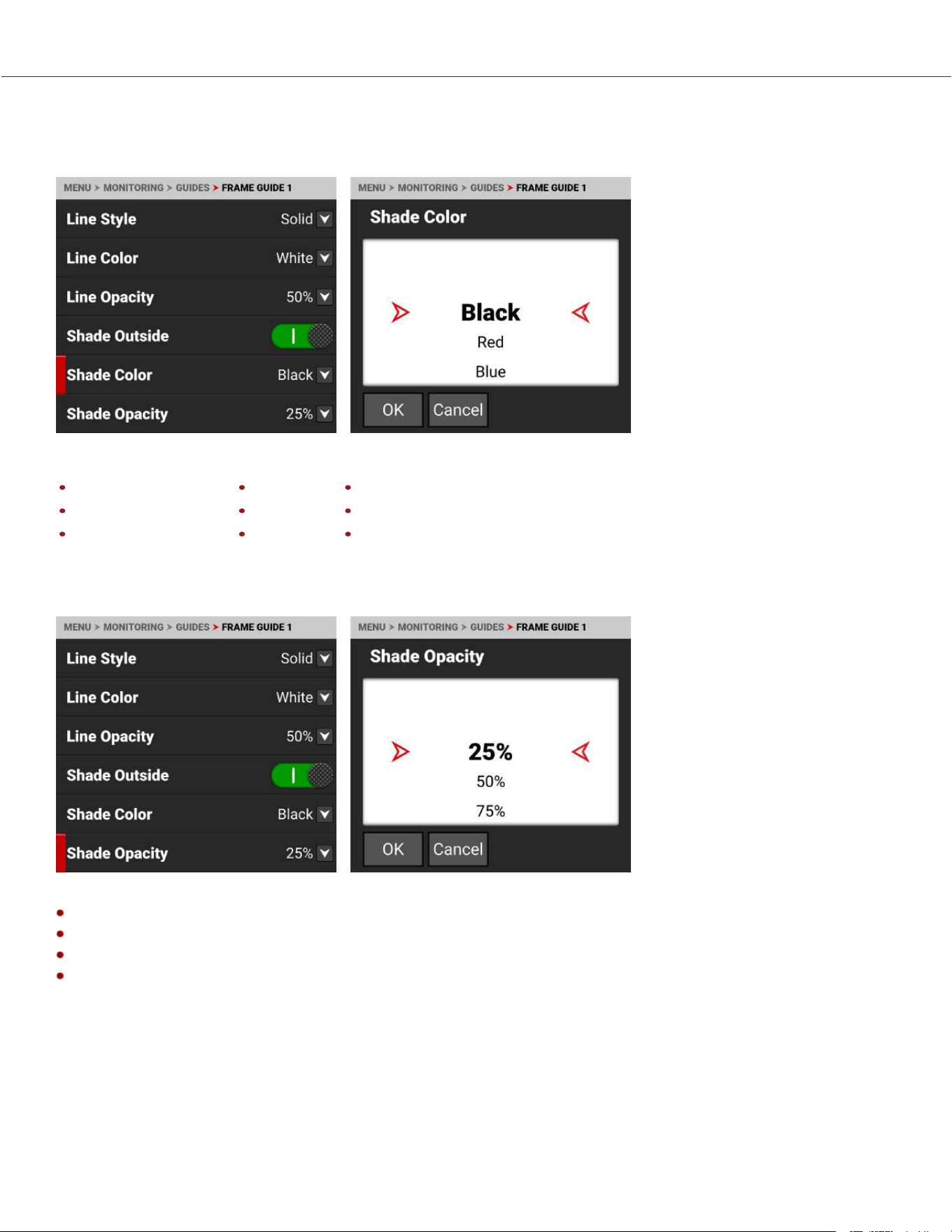
SHADE COLOR
Use Shade Color to select the color of shading to use outside of the Frame guide.
Use Shade Color to select one of the following colors for the outside shading:
Black (default) Green Cyan
Red Yellow Dark Gray
Blue Magenta White
SHADE OPACITY
Use Shade Opacity to select the opacity of the shading outside of the Frame guide.
Use Shade Opacity to select the percentage of opacity for the shading outside of the Frame Guide:
25% (default)
50%
75%
100%
COPYRIGHT © 2023 RED.COM, LLC 955-0218, REV A | 121
KOMODO-X
®
OPERATION GUIDE
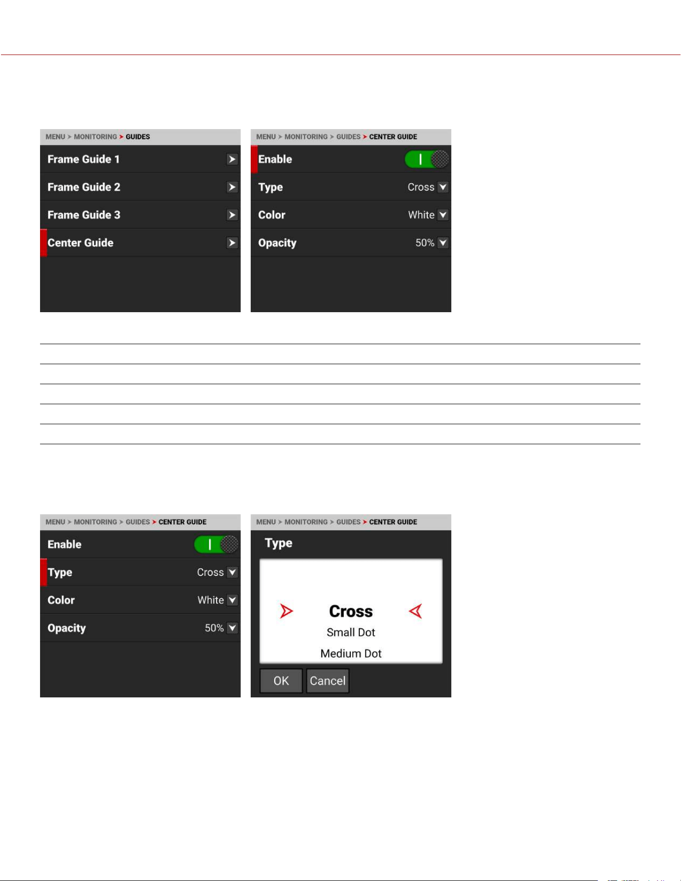
CENTER GUIDE
Use Center Guide to enable and configure the Center Guide.
Configure the Center Guide by using the following:
ITEMS DETAILS
Enable Enables the Center Guide
Type Select Center Guide type - dot or cross
Color Select a color for the Center Guide
Opacity Percentage of opacity of the guide color
TYPE
Use Type to select the type of Center Guide to display.
Use Type to select a center dot or cross (default) for the Center Guide.
COPYRIGHT © 2023 RED.COM, LLC 955-0218, REV A | 122
KOMODO-X
®
OPERATION GUIDE

COLOR
Use Color to select the color used by the Center Guide.
Use Color to select one of the following colors for the Center Guide:
Black Green Cyan
Red Yellow Dark Gray
Blue Magenta White (default)
OPACITY
Use Opacity to select how transparent the Center Guide appears.
Use Opacity to select the percentage of opacity for the Center Guide:
25%
50% (default)
75%
100%
COPYRIGHT © 2023 RED.COM, LLC 955-0218, REV A | 123
KOMODO-X
®
OPERATION GUIDE
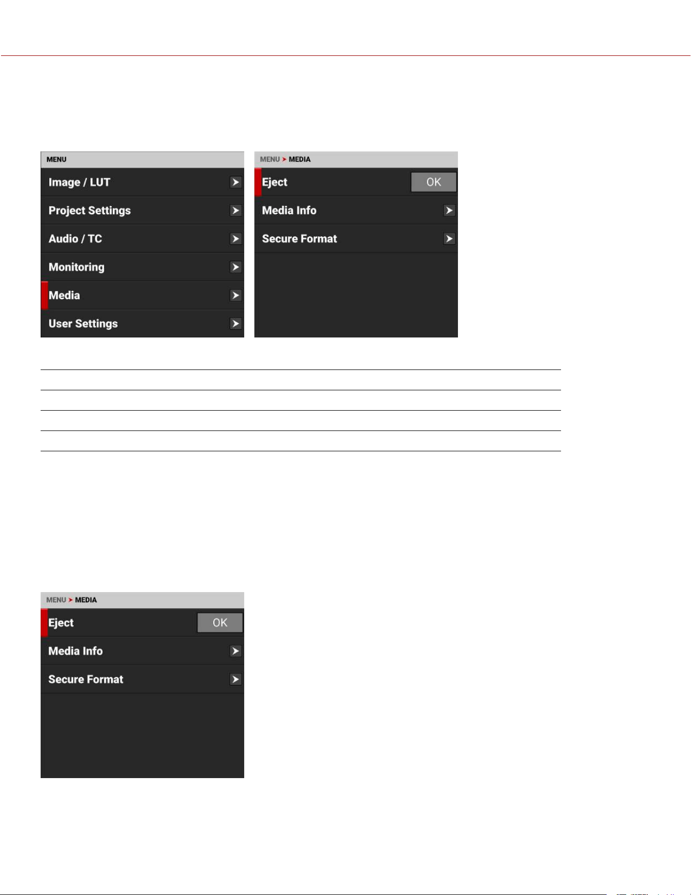
MEDIA MENU
The Media menu contains the settings you use to configure your media.
From the Onboard LCD touchscreen menu, tap Media:
Use the Media menu to configure the camera's storage media settings and to view the media information:
ITEMS DETAILS
Eject Eject the media card
Media Info View the media card information
Secure Format Performs a secure format of the media card
EJECT
Use Eject to safely unmount the media card electronically from the camera before removing it physically.
WARNING: The media can get extremely hot. Use caution when removing media.
WARNING: Do not attach a label to the media card. The heat generated by the media can weaken the label's adhesive,
causing the label to detach inside of the camera. Labels can also diminish heat dissipation and cause excessive wear to
the internal components. Removing a label from a media card can possibly deform the card body.
Access Eject from the Onboard LCD Touchscreen Media menu:
For more information, refer to Media Management.
COPYRIGHT © 2023 RED.COM, LLC 955-0218, REV A | 124
KOMODO-X
®
OPERATION GUIDE
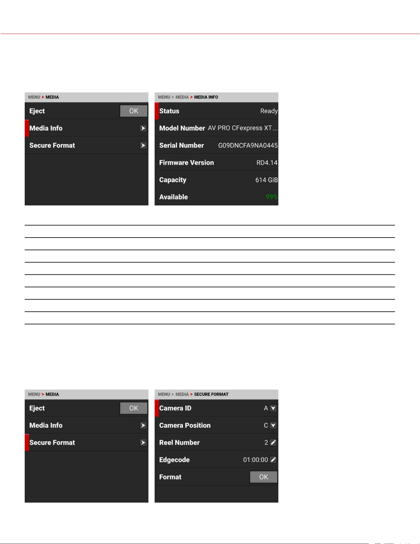
MEDIA INFO
Use Media Info to display the media card information.
Access Media Info from the Onboard LCD Touchscreen Media menu:
Media Info displays the following:
SETTING DETAILS
Status Displays the media card status
Model Number Displays the media card model number
Serial Number Displays the media card serial number
Firmware Version Displays the media card firmware version
Capacity Displays the media card total capacity
Available Displays the media card's remaining storage
Time Remaining Displays the recording time remaining on the media card
SECURE FORMAT
Use Secure Format to format the media card down to the file system level.
A secure format allows you to rebuild the card file system.
WARNING: Secure Format permanently deletes all information from the media card. Data cannot be recovered after a
Secure Format.
COPYRIGHT © 2023 RED.COM, LLC 955-0218, REV A | 125
KOMODO-X
®
OPERATION GUIDE
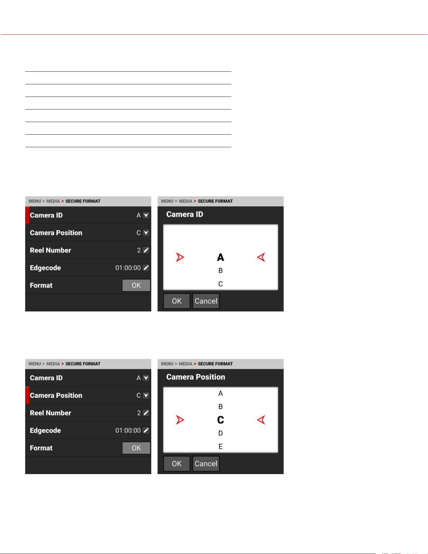
Use the Secure Format menu to update the following information:
SETTING DETAILS
Camera ID Select the camera ID (default is A)
Camera Position Select the camera position (default is C)
Reel Number Select the reel number (default is 1)
Edgecode Enter the time number (default is 01:00:00)
Format Starts the Secure formatting process
For more information, refer to Secure Format.
CAMERA ID
Use Camera ID to assign a camera ID letter to the media.
The Camera ID letters you can assign range from A-Z. For more information, refer to Secure Format.
CAMERA POSITION
Use Camera Position to select the camera position label for the media card.
The Camera Position letters you can assign range from A-Z. For more information, refer to Secure Format.
COPYRIGHT © 2023 RED.COM, LLC 955-0218, REV A | 126
KOMODO-X
®
OPERATION GUIDE
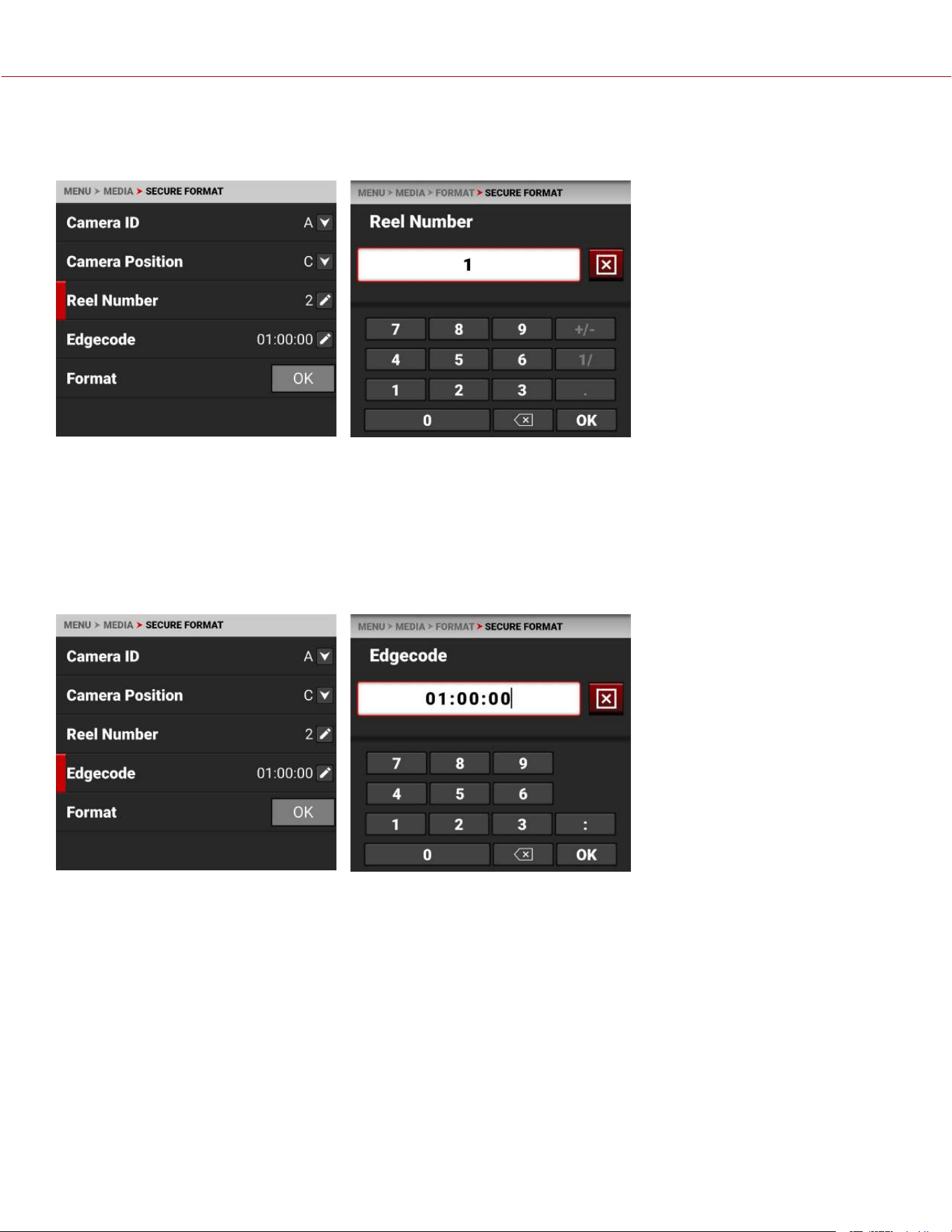
REEL NUMBER
Use Reel Number to assign a reel number to the media.
Use the keypad to enter a unique reel number to the media.
NOTE: It is best practice to keep your reel numbers to no longer than seven characters in length to conform with all edit
decision list (EDL) formats.
For more information, refer to Secure Format.
EDGECODE
Use Edgecode to assign an edgecode to the media.
Use the keypad to enter a unique edgecode number to the media.
Edgecode is a SMPTE Timecode track, which by default starts at 01:00:00 on the first frame of each media card. It is a
sequential code that is continuous from frame to frame and also between clips. Edgecode is equivalent to RUN
RECORD as used on broadcast cameras.
For more information, refer to Secure Format.
COPYRIGHT © 2023 RED.COM, LLC 955-0218, REV A | 127
KOMODO-X
®
OPERATION GUIDE
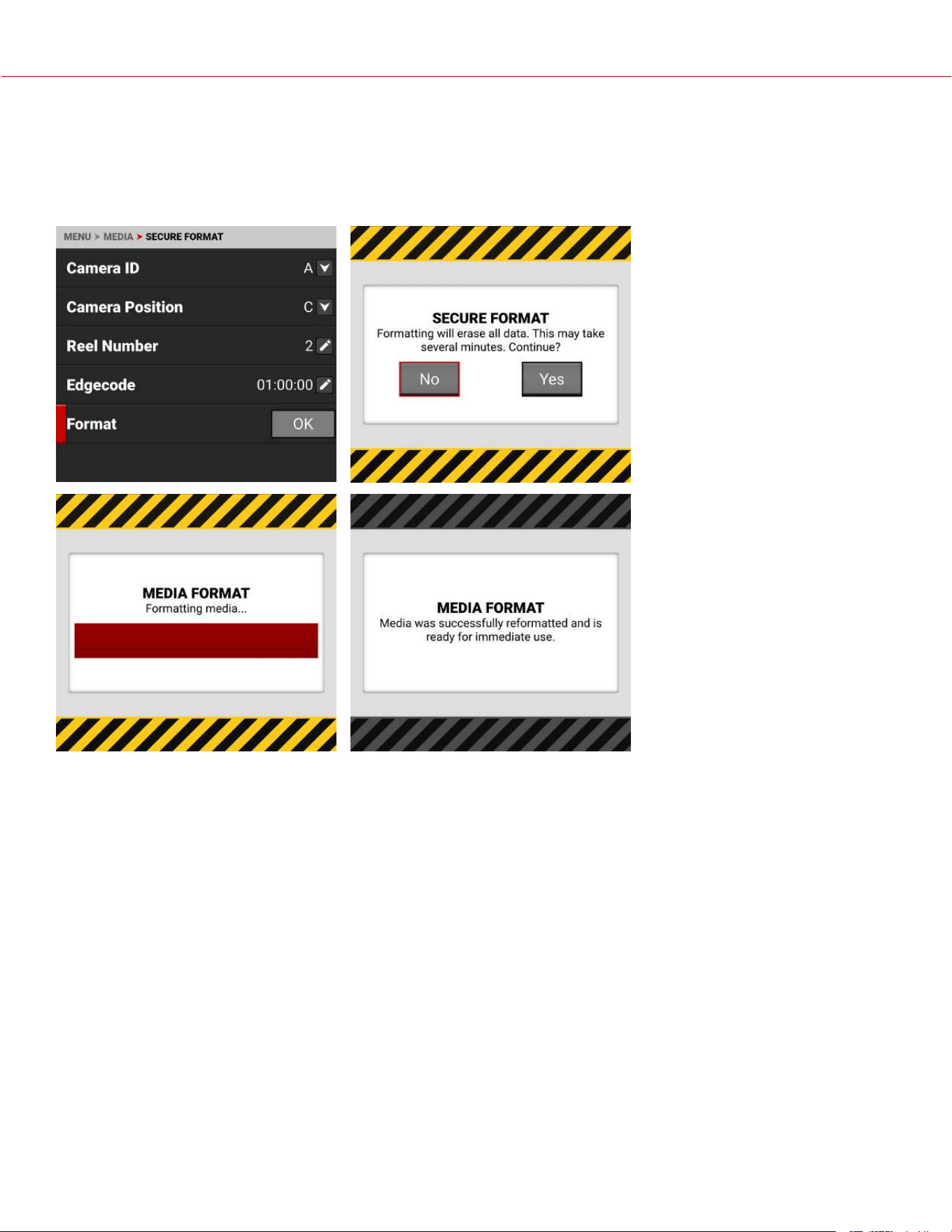
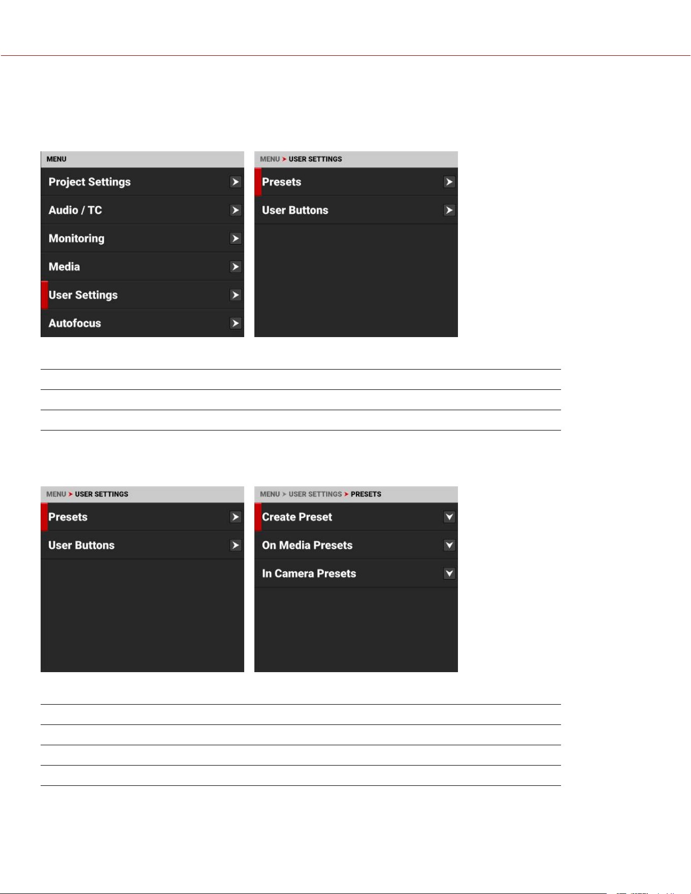
USER SETTINGS MENU
The User Settings menu contains the settings you use to create presets and assign User button functions.
From the Onboard LCD touchscreen menu, select User Settings:
Use the User Settings menu to configure presets and User buttons:
ITEMS DETAILS
Presets Configure and manage presets
User Buttons Assign functions to the user buttons
PRESETS
Use Presets to build and select pre-configured settings for the camera.
The Presets menu contains the following:
ITEMS DETAILS
Create Preset Create camera setting presets
On Media Presets Manage presets stored on the media
In Camera Presets Manage presets stored in the camera
COPYRIGHT © 2023 RED.COM, LLC 955-0218, REV A | 129
KOMODO-X
®
OPERATION GUIDE
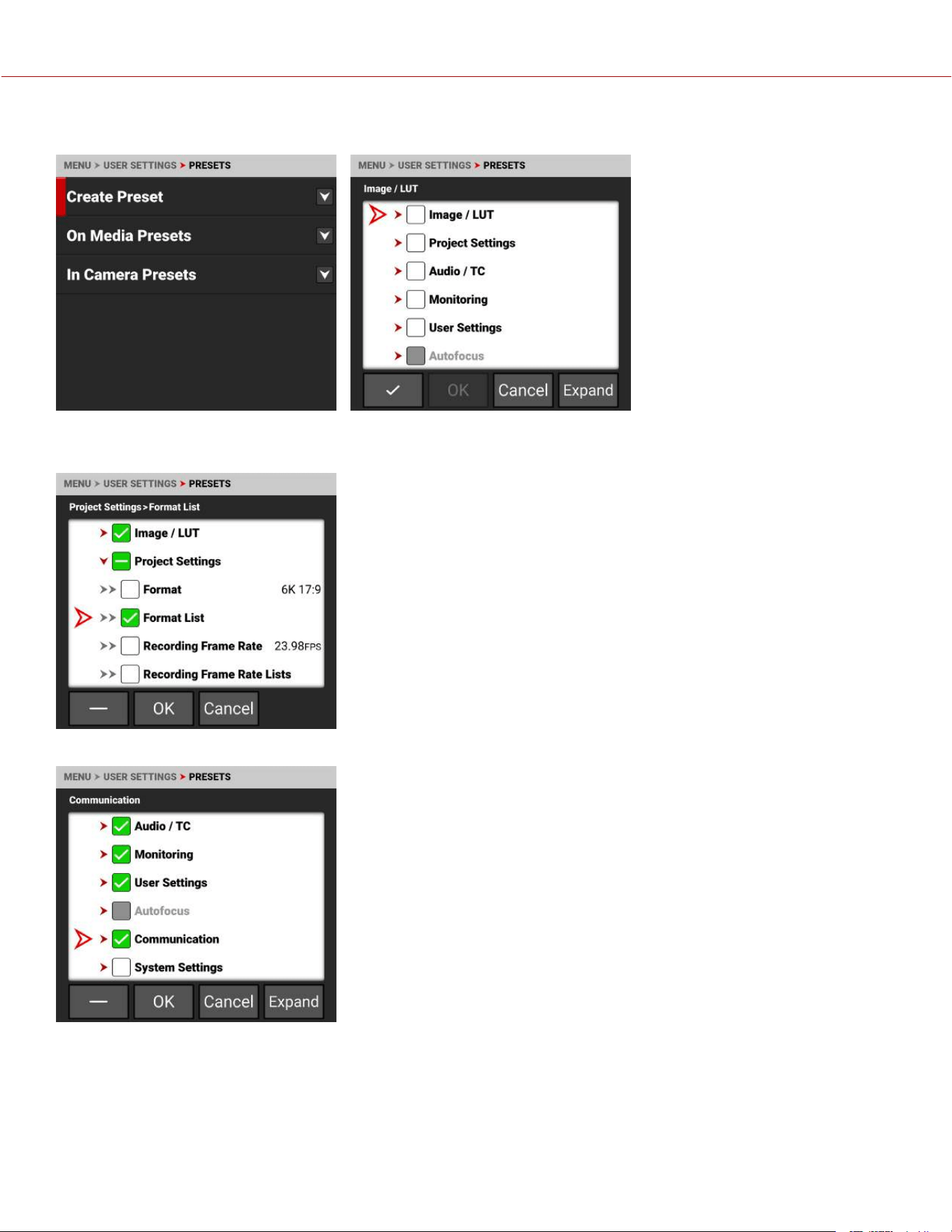
CREATE PRESET
Use Create Preset to select the current camera settings you want to use to create a preset list of settings.
You can select settings individually:
You can also use the menu checkmark button to select all of a menus settings as a preset:
COPYRIGHT © 2023 RED.COM, LLC 955-0218, REV A | 130
KOMODO-X
®
OPERATION GUIDE
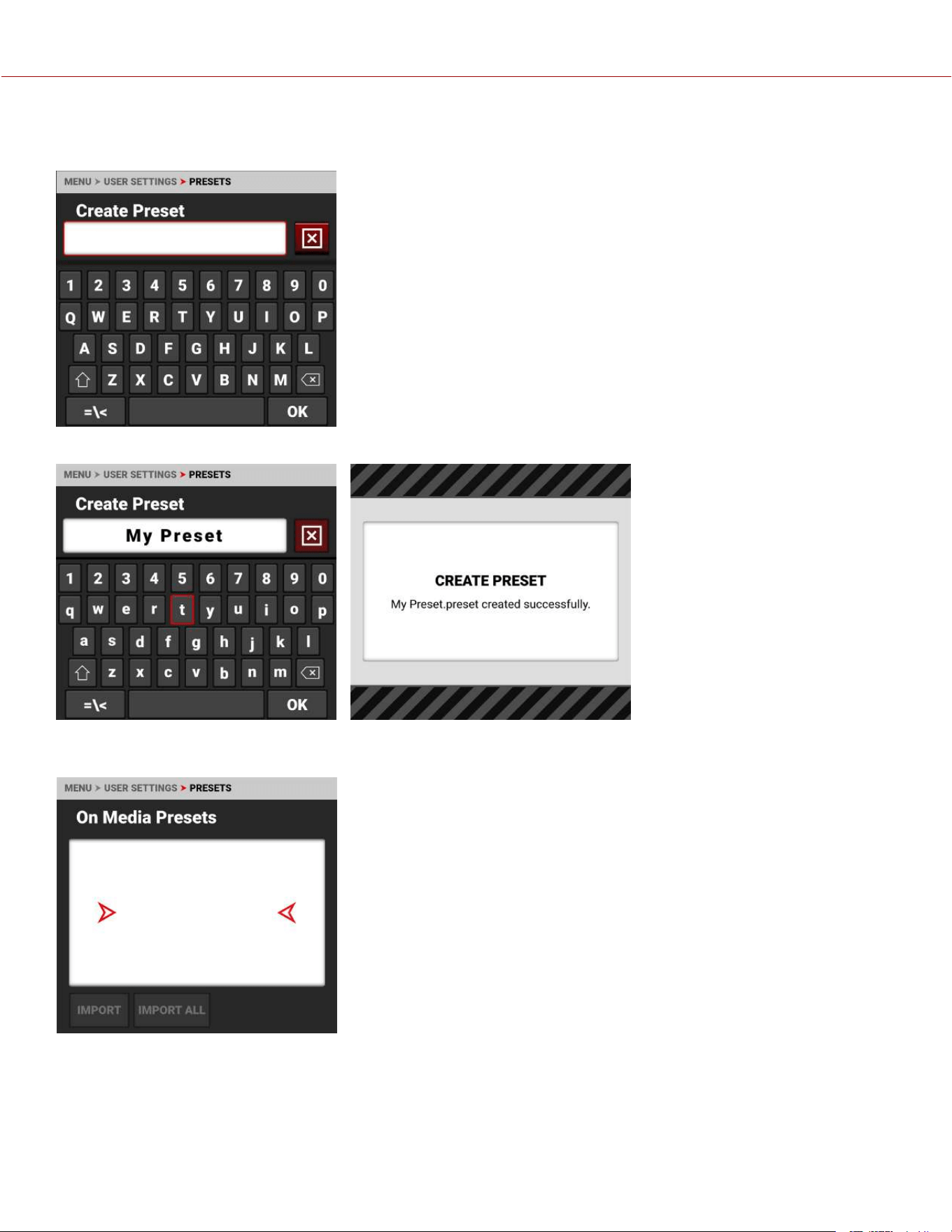
Click OK to create the preset. The Create Preset screen opens. Enter your Preset name and tap OK. The Preset is
saved to the camera.
Enter your Preset name and tap OK. The Preset is saved to the camera (refer to In Camera Presets).
ON MEDIA PRESETS
You can import presets from the media to the camera. When importing
presets from the media to the camera, the presets are saved to a folder on
the camera called “presets”.
From On Media Presets, you can import the selected preset from the media
to the camera or import all of the presets from the media to the camera.
COPYRIGHT © 2023 RED.COM, LLC 955-0218, REV A | 131
KOMODO-X
®
OPERATION GUIDE
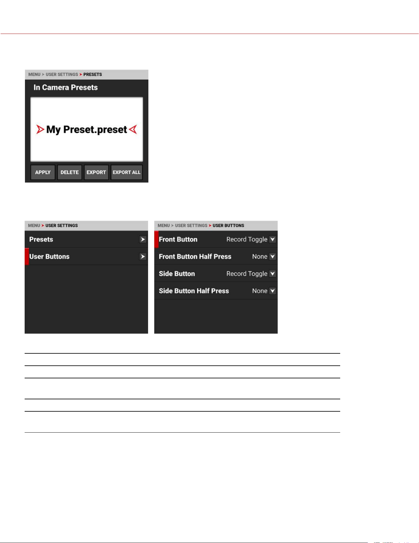
IN CAMERA PRESETS
You can export presets from the camera to the media. When exporting
presets from the camera to the media, the presets are saved to a folder on
the media called “presets”.
From In Camera Presets, you can apply the selected preset to the camera,
delete the selected preset from the camera, export the selected preset from
the camera to the media, or export all of the presets from the camera to the
media.
USER BUTTONS
Use User Buttons to assign functions to the front and side user buttons.
The User Buttons menu contains the following:
ITEMS DETAILS
Front Button Assign functions to the front user button
Front Button Half
Press
Assign functions to the front button half press
Side Button Assign functions to the side user button
Front Button Half
Press
Assign functions to the side user button half press
COPYRIGHT © 2023 RED.COM, LLC 955-0218, REV A | 132
KOMODO-X
®
OPERATION GUIDE
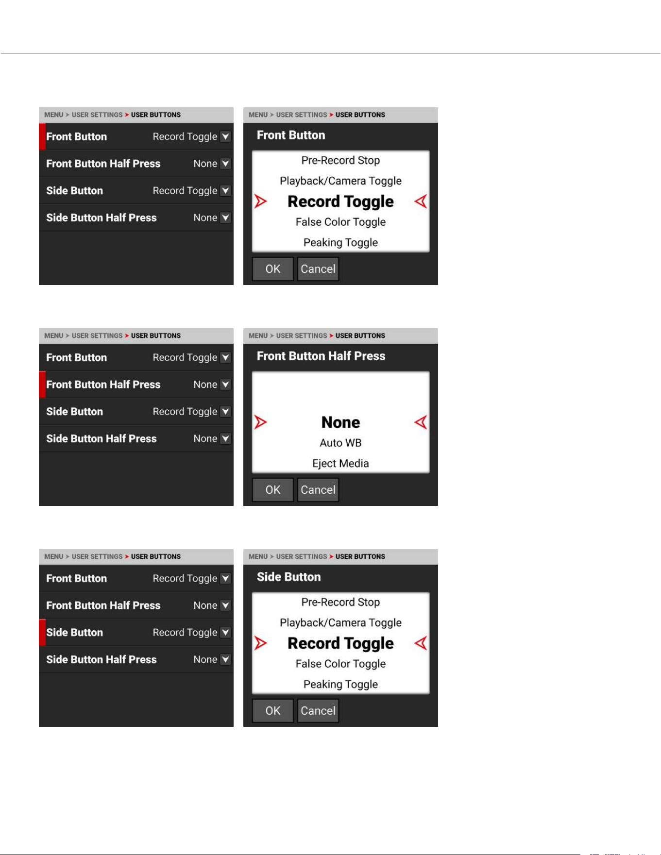
FRONT BUTTON
Use Front Button to select the
function you want assigned to the
front camera button.
The default setting is Record
Toggle.
Refer to User Button Assignable
Functions for the options.
FRONT BUTTON HALF PRESS
Use Front Button Half Press to
select the function you want
assigned to the front camera
button for a half press.
The default setting is None.
Refer to User Button Assignable
Functions for the options.
SIDE BUTTON
Use Side Button to select the
function you want assigned to the
side camera button.
The default setting is Record
Toggle.
Refer to User Button Assignable
Functions for the options.
COPYRIGHT © 2023 RED.COM, LLC 955-0218, REV A | 133
KOMODO-X
®
OPERATION GUIDE
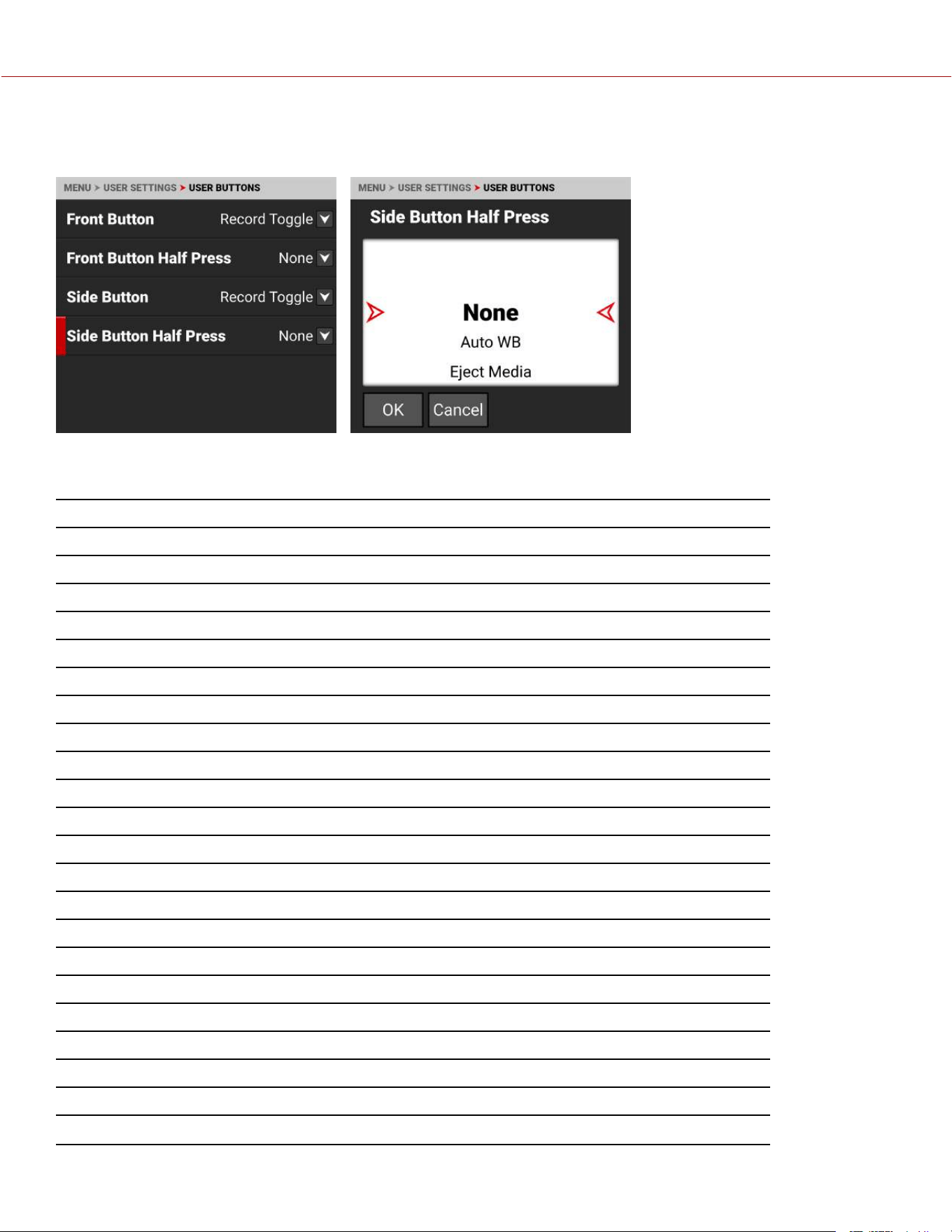
SIDE BUTTON HALF PRESS
Use Side Button Half Press to
select the function you want
assigned to the side camera button
for a half press.
The default setting is None.
Refer to User Button Assignable
Functions for the options.
USER BUTTON ASSIGNABLE FUNCTIONS
ITEM DETAILS
None Nothing is assigned to the User Slot
Apply Preset Apply the presets stored on the camera
Auto WB Camera automatically adjusts the White Balance
Eject Media Unmount the media in preparation for removal
Secure Format Format the media
Eject USB-C Drive Eject device connected to USB-C port
Jam TCto TOD Jam Timecode to time of day
AF Toggle Toggle the selected autofocus mode
AF Hold Activates autofocus while pressed
Save Log Save the log file to the media
LCDs Magnify Toggle Toggle the magnification feature on and off for all LCDs
SDI Magnify Toggle Toggle the SDI port magnification feature on and off
Pre-Record Toggle Toggle the Pre-Record feature on and off
Pre-Record Stop Stop the Pre-Record feature
Playback/Camera Toggle Toggle between camera output and clip playback
Record Toggle (default) Toggle record on and off
False Color Toggle Toggle the False Color tools on and off
Peaking Toggle Toggle the Peaking tools on and off
Log View Toggle Toggle Log view on and off
Zebra 1 Toggle Toggle Zebra 1 on and off
Zebra 2 Toggle Toggle Zebra 2 on and off
LCD Guides Toggle Toggle the Guides on and off on the Onboard LCD
COPYRIGHT © 2023 RED.COM, LLC 955-0218, REV A | 134
KOMODO-X
®
OPERATION GUIDE

ITEM DETAILS
LCD Tools Toggle Toggle the Tools on and off on the Onboard LCD
SDI Guides Toggle Toggle the Guides on and off on SDI output
SDI Tools Toggle Toggle the Tools on and off on the SDI output
SDI Overlay Toggle Toggle between the simple and advanced Overlay on the SDI output
Top LCD Guides Toggle Toggle the Guides on and off on the DSMC3™ RED® Touch 7.0" LCD
Top LCD Tools Toggle Toggle the Tools on and off on the DSMC3™ RED® Touch 7.0" LCD
Frame Guide 1 Toggle Toggle Frame Guide 1 on and off
Frame Guide 2 Toggle Toggle Frame Guide 2 on and off
Frame Guide 3 Toggle Toggle Frame Guide 3 on and off
Center Guide Toggle Toggle the Center Guide on and off
Iris Open Open the iris
Iris Close Close the iris
ND Increment Increase the ND setting by one increment
ND Decrement Decrease the ND setting by one increment
Shutter Decrement Decrease the shutter setting by one increment
Shutter Increment Increase the shutter setting by one increment
Sync Shift Increment (1) Increase the sync shift setting by one increment
Sync Shift Decrement (1) Decrease the sync shift setting by one increment
Sync Shift Increment (100) Increase the sync shift setting by 100 increments
Sync Shift Decrement (100) Decrease the sync shift setting by 100 increments
Sync Shift Increment (1000) Increase the sync shift setting by 1000 increments
Sync Shift Decrement (1000) Decrease the sync shift setting by 1000 increments
COPYRIGHT © 2023 RED.COM, LLC 955-0218, REV A | 135
KOMODO-X
®
OPERATION GUIDE
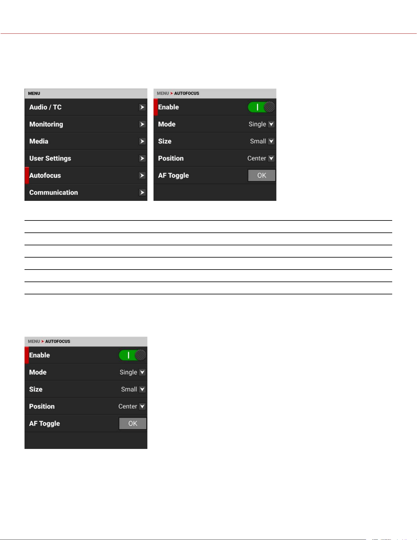
AUTOFOCUS MENU
Use Autofocus to enable and configure the camera's Autofocus feature. The lens must support autofocus for this
feature to work.
Use the Autofocus menu to perform camera autofocus tasks:
ITEM DETAILS
Enable Enable/Disable the Autofocus feature
Mode Select the Autofocus mode
Size Select the size of the Autofocus area
Position Select the position of the Autofocus area
AF Toggle Toggle the selected Autofocus mode off and on
ENABLE
Use Enable to enable or disable the Autofocus Menu feature. The lens must support autofocus for the camera to use
this feature.
COPYRIGHT © 2023 RED.COM, LLC 955-0218, REV A | 136
KOMODO-X
®
OPERATION GUIDE
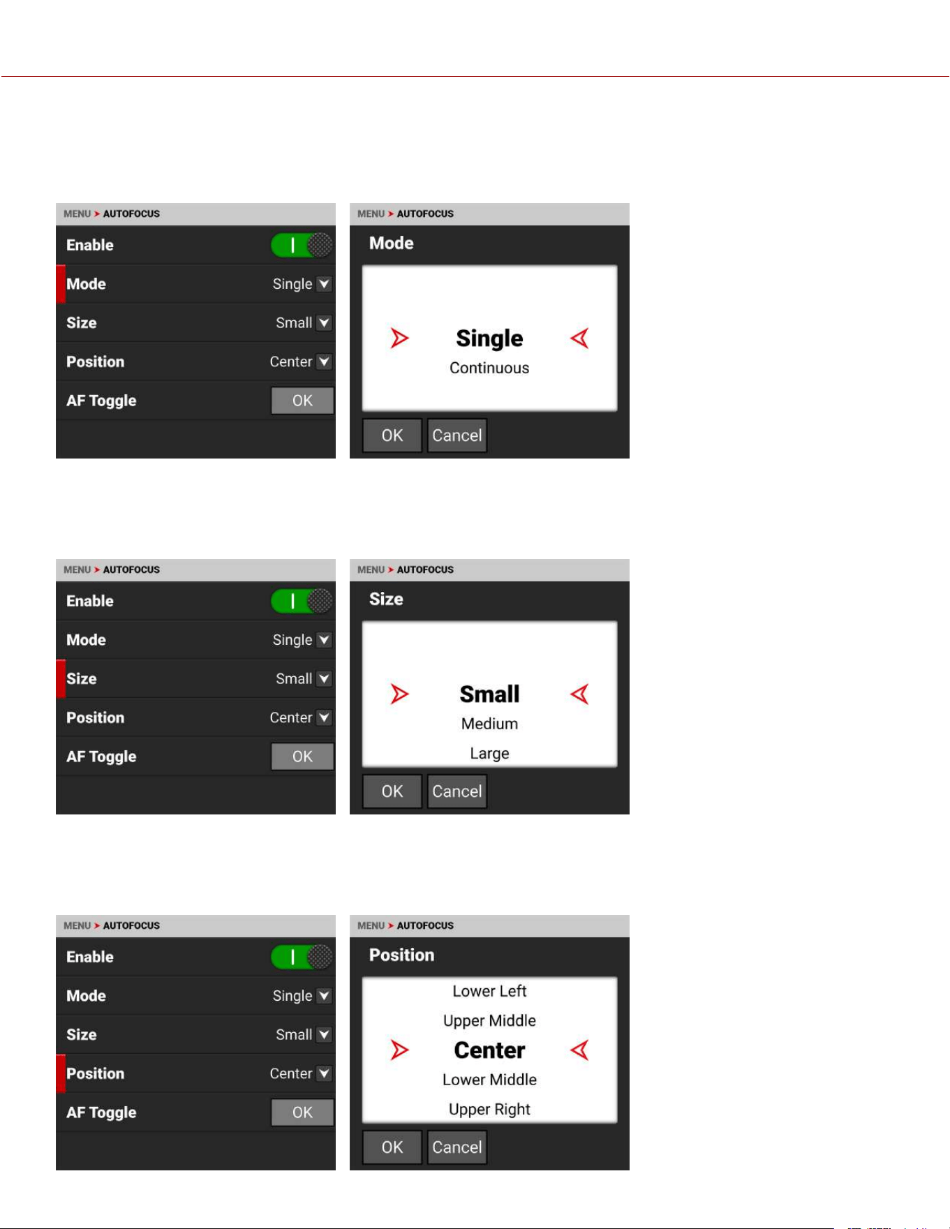
MODE
Use Mode to select the autofocus mode for the camera. The lens must support autofocus for the camera to use this
feature.
SINGLE MODE (DEFAULT)
Use single mode to autofocus and
then stop at that focus position.
CONTINUOUS MODE
Use Continuous mode to continue
to change focus to keep a moving
subject in focus.
SIZE
Use Size to choose what size area you want the camera to use for the autofocus feature. The lens must support
autofocus for the camera to use this feature.
The Size selections for the
autofocus area are Small (default),
Medium, Large, Wide, and Vertical.
POSITION
Use Position to specify the position of the autofocus area on the sensor. The lens must support autofocus for the
camera to use this feature.
COPYRIGHT © 2023 RED.COM, LLC 955-0218, REV A | 137
KOMODO-X
®
OPERATION GUIDE
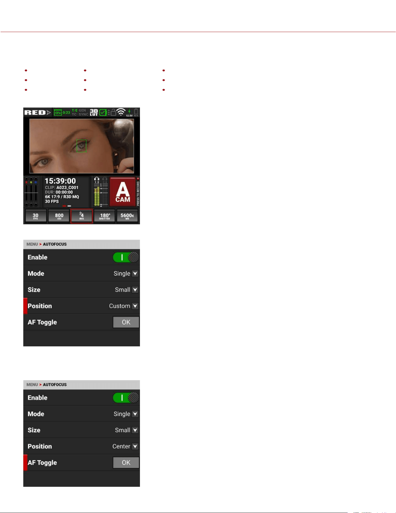
The Position selections include:
Left Upper Middle Upper Right
Upper Left Center (default) Lower Right
Lower Left Lower Middle Right
The Autofocus Position rectangle displays on the screen:
You can move the position manually on the LCD screen. The menu will change to display Custom.
AF TOGGLE
AF Toggle will have different behaviors depending on the Autofocus Mode.
Single Mode: AF Toggle activates a single autofocus command to focus on
the subject in the Autofocus box, and then it stops. Each activation of AF
Toggle repeats this process.
Continuous Mode: Continuous mode continuously focuses the camera on
the subject in the Autofocus box. AF Toggle allows you to stop and start this
feature. This control is helpful when you are moving the camera, such as
when panning from one subject to another. Tap AF Toggle to disable
Continuous autofocus during the pan, to ensure the camera does not attempt
to focus during the panning action, and then tap AF Toggle again once the
AF Box is over the subject on which you want focus.
COPYRIGHT © 2023 RED.COM, LLC 955-0218, REV A | 138
KOMODO-X
®
OPERATION GUIDE
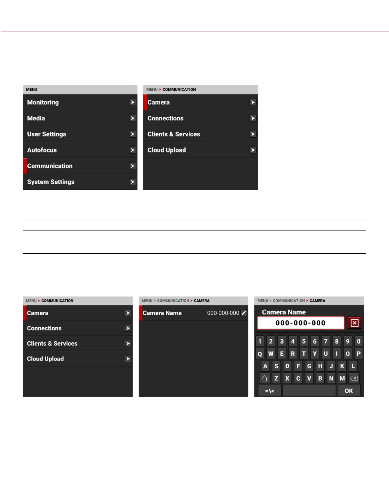
COMMUNICATION MENU
The Communication menu contains the settings you use to configure your camera to communicate with other devices.
From the camera LCD menu, navigate to, and tap, Communication:
Use the Communication menu to configure the camera's communication settings:
ITEM DETAILS
Camera Setting for the camera name
Connections Settings for USB-C, Wi-Fi, and Serial communication
Clients & Services Settings for FTPS and PTP communication
Cloud Upload Settings for Frame.io and AWS S3 communication
CAMERA
Use the Camera menu to view and edit the camera name. Select Camera Name to open the Camera Name editor.
COPYRIGHT © 2023 RED.COM, LLC 955-0218, REV A | 139
KOMODO-X
®
OPERATION GUIDE
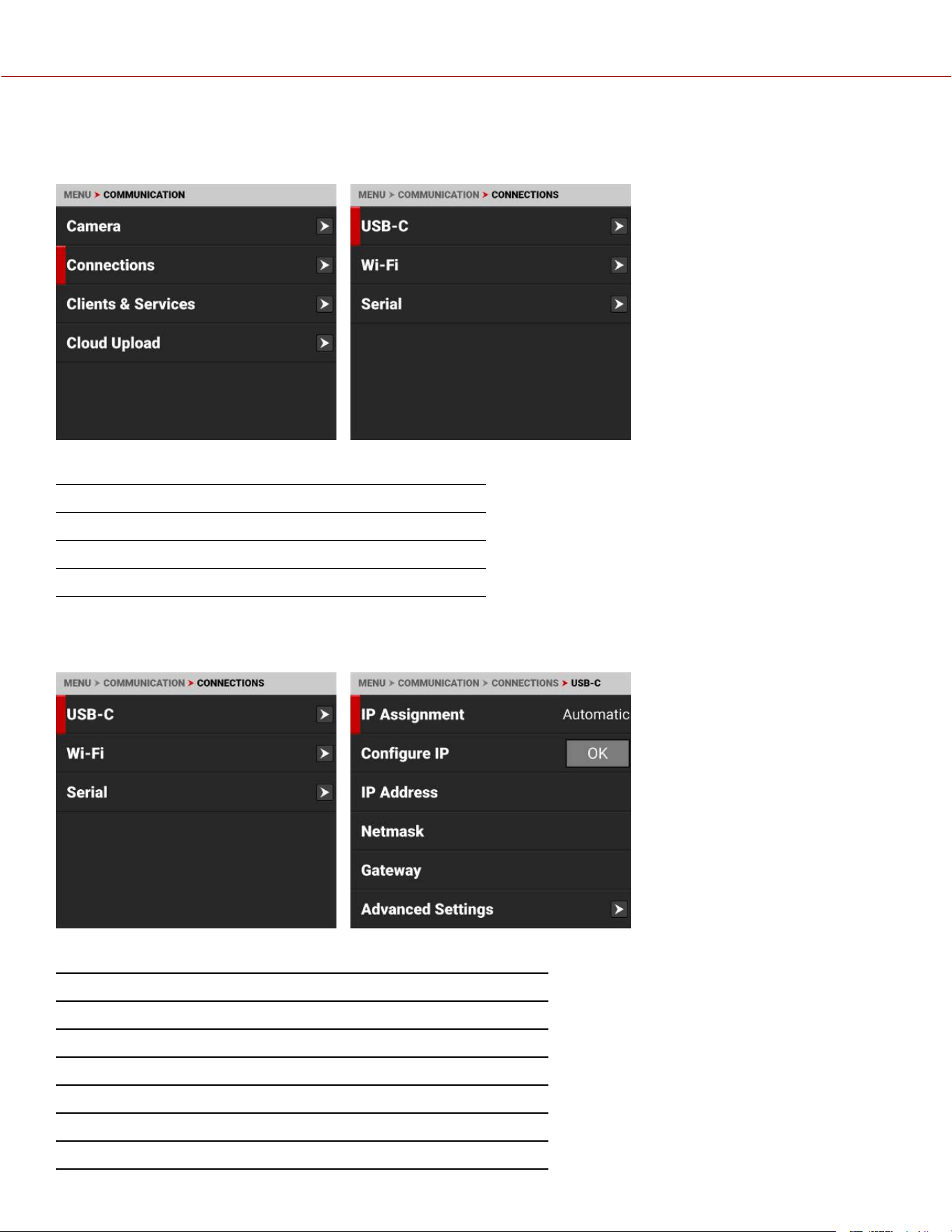
CONNECTIONS
Use the Connections menu to select the connection you want to configure.
Use the Connections menu to configure the camera's connection settings:
ITEM DETAILS
USB-C Select the camera USB-C connection settings
Wi-Fi Configure the camera Wi-Fi connection settings
Serial Configure the camera serial connection settings
USB-C
Use USB-C to configure the connection to the USB-C port.
The settings you can configure for the USB-C port include:
ITEM DETAILS
IP Assignment Displays the IP address assignment method
Configure IP IP Address modes and configuration settings
IP Address View or enter the network IP address
Netmask View or enter the network Netmask
Gateway View or enter the network Gateway
Advanced Settings Change the MTU size
COPYRIGHT © 2023 RED.COM, LLC 955-0218, REV A | 140
KOMODO-X
®
OPERATION GUIDE
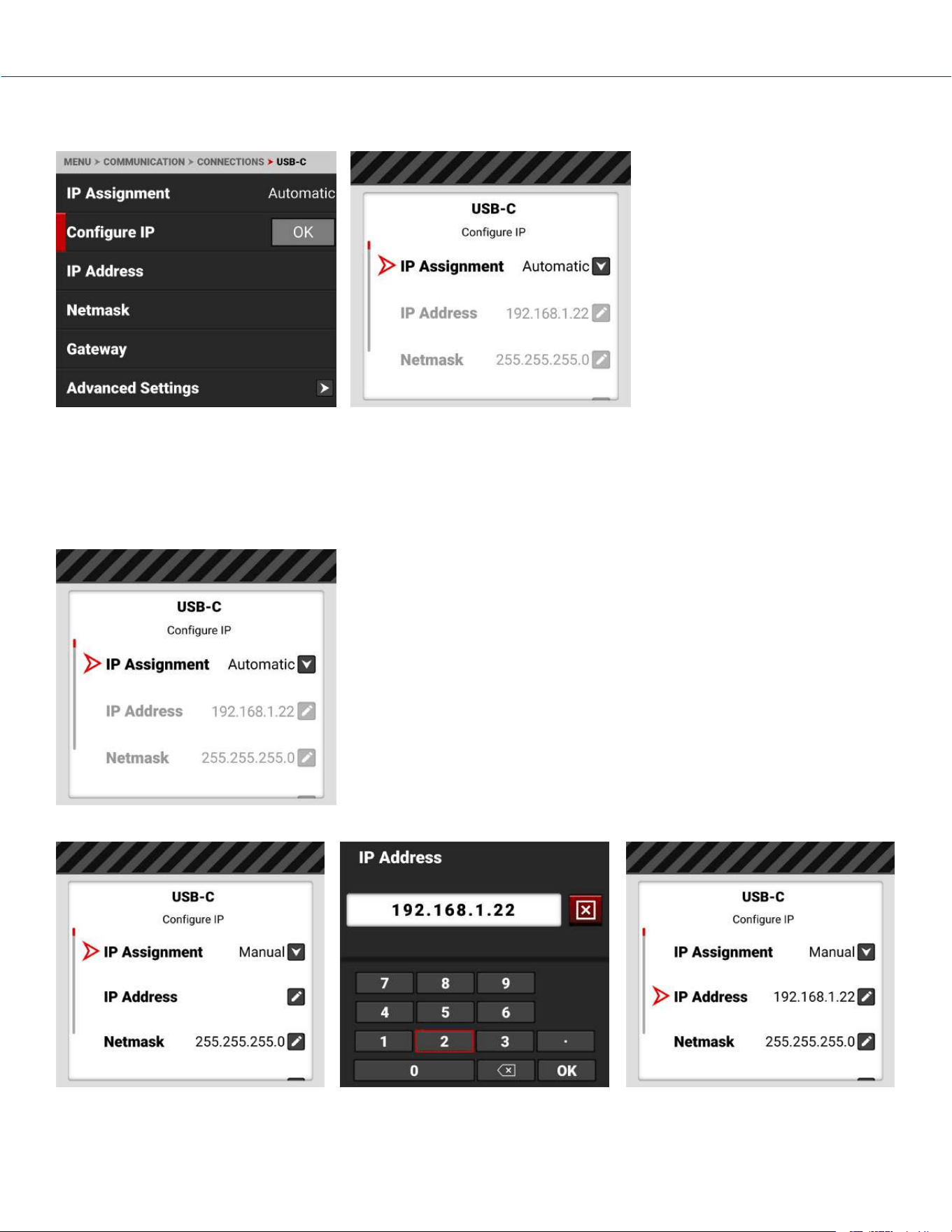
CONFIGURE IP
When connected to an Ethernet network, this allows you to automatically detect an IP address or to manually enter an
IP address, Netmask address, and Gateway (router) address.
IP ADDRESS
When connected to an Ethernet network and Automatic IP Assignment is enabled, IP Address displays the network IP
address.
When Manual IP Assignment is enabled, you can select IP Address and manually enter a static IP address.
COPYRIGHT © 2023 RED.COM, LLC 955-0218, REV A | 141
KOMODO-X
®
OPERATION GUIDE
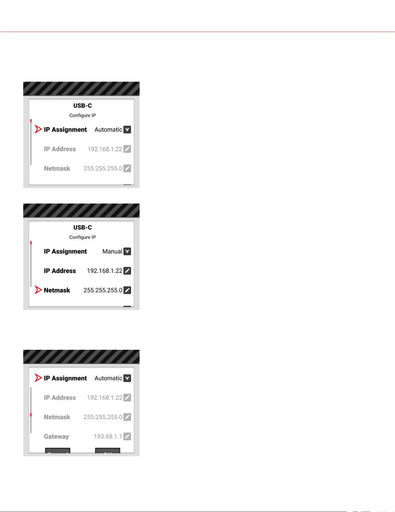
NETMASK
When connected to an Ethernet network and Automatic IP Assignment is enabled, Netmask displays the network
Netmask address.
When Manual IP Assignment is enabled, 255.255.255.0 is automatically populated as the Netmask address.
GATEWAY
When connected to an Ethernet network and Automatic IP Assignment is enabled, Gateway displays the network
Gateway address (router address).
COPYRIGHT © 2023 RED.COM, LLC 955-0218, REV A | 142
KOMODO-X
®
OPERATION GUIDE
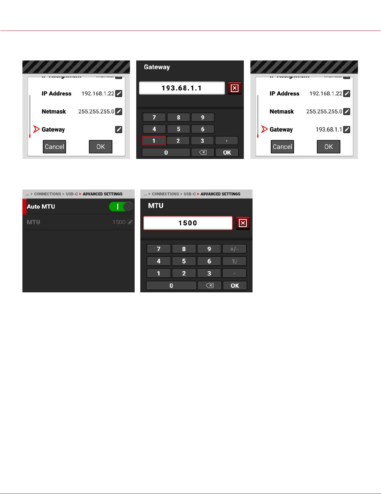
When Manual IP Assignment is enabled, you can select Gateway and manually enter a Gateway (router) address.
ADVANCED SETTINGS
The USB-C Advanced Settings menu allows you to change the MTU size.
The Auto setting MTU size is 1500 bytes. You can set the MTU to a size larger than the standard 1500 bytes. This
works best on fast Ethernet connections like Gigabit LAN. These large MTUs are known as Jumbo frames (as large as
9000 bytes) and they can increase data transmission efficiency and reduce overhead. However, Jumbo frame error
correction is slower as a result of re-sending larger packets.
COPYRIGHT © 2023 RED.COM, LLC 955-0218, REV A | 143
KOMODO-X
®
OPERATION GUIDE
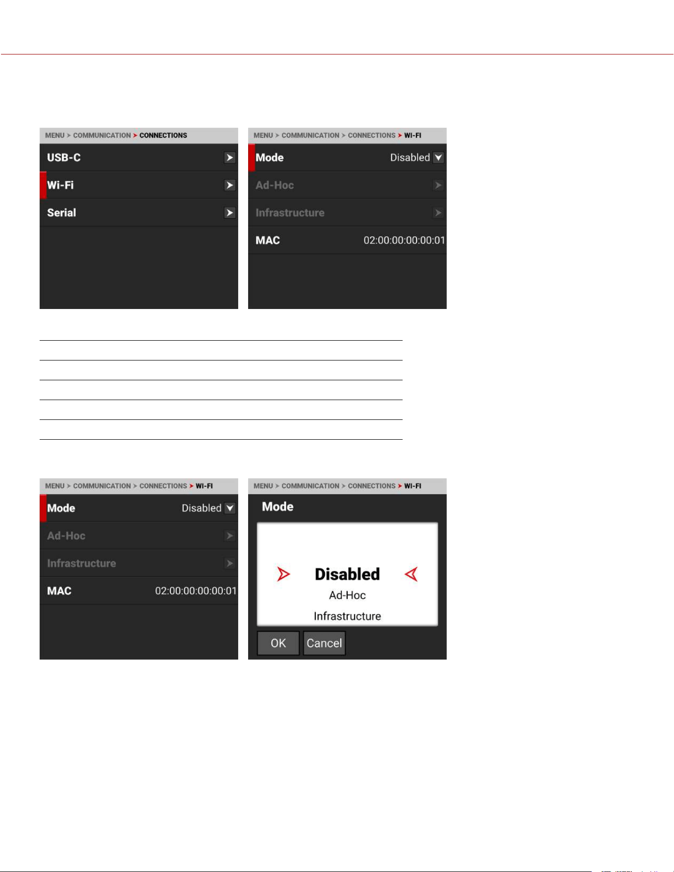
WI-FI
Use Wi-Fi to configure the camera to work with a Wi-Fi connection.
Use the Wi-Fi menu to configure the camera's Wi-Fi settings:
ITEM DETAILS
Mode Disable Wi-Fi or select the camera Wi-Fi settings
Ad-Hoc Configure the camera as a Wi-Fi hot spot
Infrastructure Settings for connecting to an existing Wi-Fi network
MAC Displays the camera device MAC address
MODE
From Mode you can disable the Wi-Fi network, or you can enable the camera's Ad-Hoc or Infrastructure Wi-Fi settings.
The default setting is Disabled.
COPYRIGHT © 2023 RED.COM, LLC 955-0218, REV A | 144
KOMODO-X
®
OPERATION GUIDE
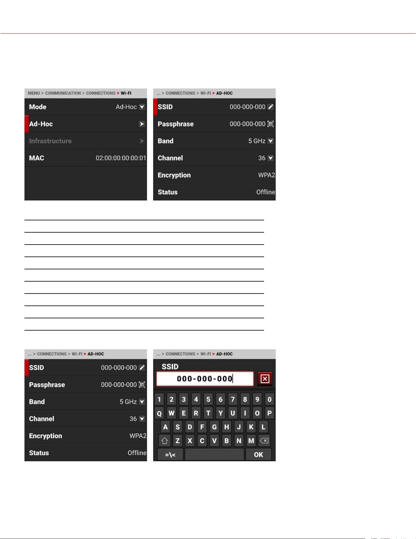
AD-HOC
Use Ad-Hoc to configure the camera as a Wi-Fi hot spot.
NOTE: The Ad-Hoc menu is enabled when the Wi-Fi Mode is set to Ad-Hoc.
Use the Ad-Hoc menu to configure the Wi-Fi hot spot settings:
ITEM DETAILS
SSID Enter the name of the Wi-Fi network the camera generates
Passphrase Enter the password for the Wi-Fi network
Band Select the Wi-Fi frequency band
Channel Select the optimal channel for the Wi-Fi band
Encryption Displays the encryption type
Status Displays the connection status
IP Address Displays the IP address
Netmask Displays the Netmask
SSID
Use the keypad to enter the camera's Wi-Fi network name.
COPYRIGHT © 2023 RED.COM, LLC 955-0218, REV A | 145
KOMODO-X
®
OPERATION GUIDE
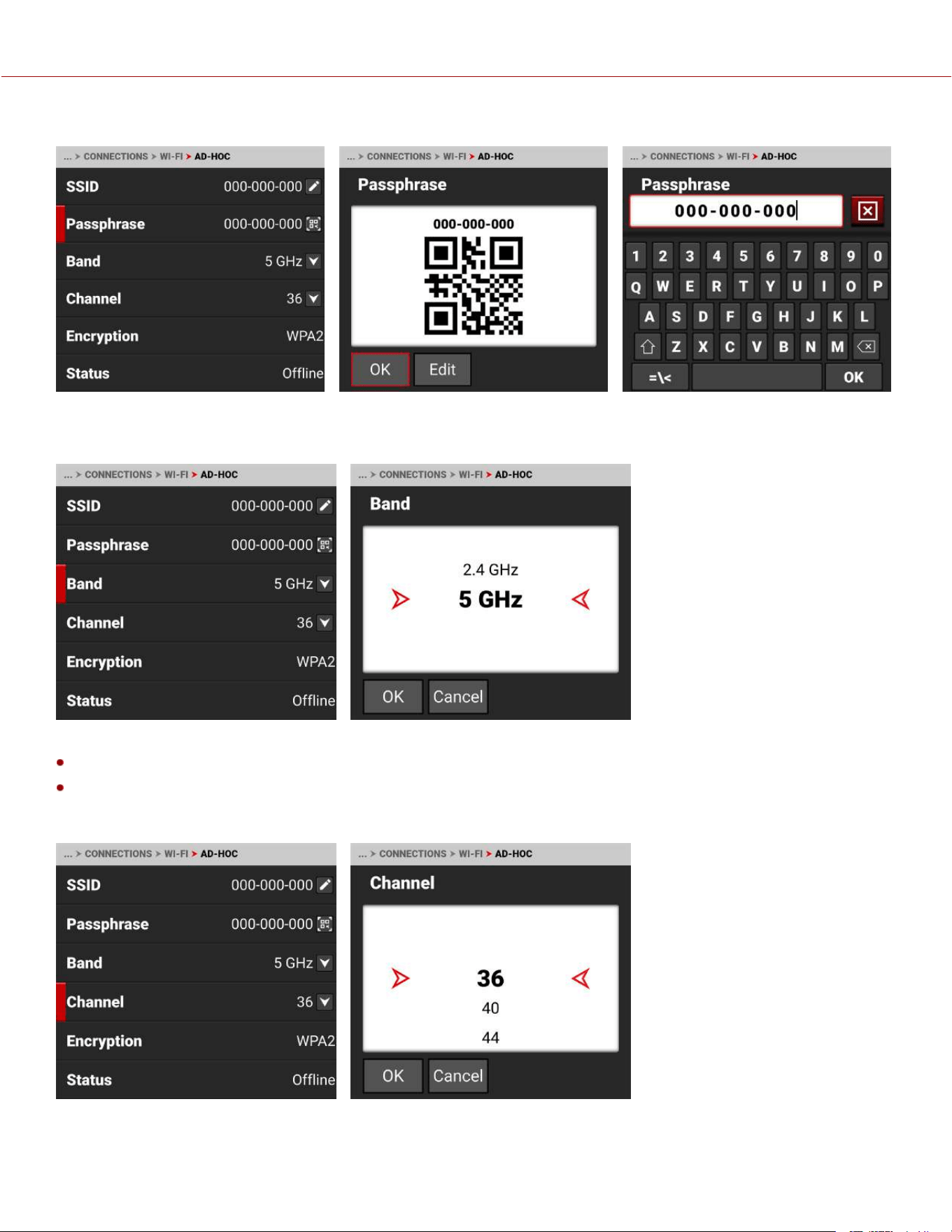
PASSPHRASE
Use the keypad to enter the camera's Wi-Fi passphrase. The camera creates a QR code version of the passphrase.
BAND
Select the camera's Wi-Fi network frequency band.
Use 5 GHz for optimal wireless video streaming performance (default)
Use 2.4 GHz for extended range remote control (when not utilizing wireless video streaming)
CHANNEL
Select the optimal channel for the selected band, one which receives the least interference from the surrounding Wi-Fi
signals.
COPYRIGHT © 2023 RED.COM, LLC 955-0218, REV A | 146
KOMODO-X
®
OPERATION GUIDE
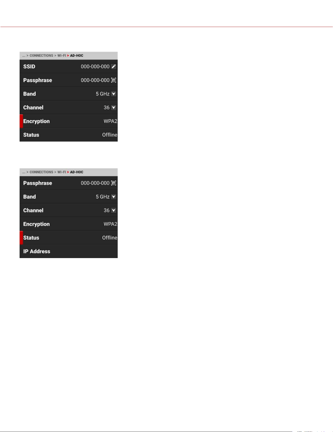
ENCRYPTION
The camera uses WPA2 security encryption.
STATUS
Status displays the camera's Ad-Hoc Wi-Fi connection status.
The Ad-Hoc status includes Offline and Online.
IP ADDRESS
When online and broadcasting a network, the camera displays an IP address.
NETMASK
When online and broadcasting a network, the camera displays the Netmask for the IP address.
COPYRIGHT © 2023 RED.COM, LLC 955-0218, REV A | 147
KOMODO-X
®
OPERATION GUIDE
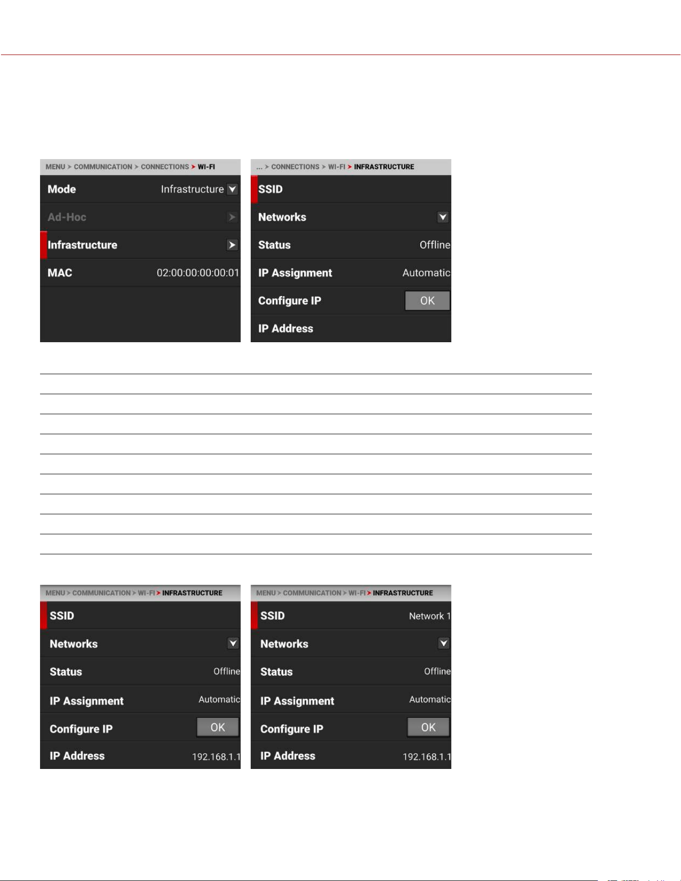
INFRASTRUCTURE
Use Infrastructure to configure the camera to connect to an existing Wi-Fi network.
NOTE: The Infrastructure menu is enabled when the Wi-Fi Mode is set to Infrastructure. Refer to the Wi-Fi section for
more information.
Use the Infrastructure menu to configure the Wi-Fi settings to connect to an existing Wi-Fi infrastructure:
ITEM DETAILS
SSID Displays the name of the connected Wi-Fi network
Networks Scan for, select, or enter the Wi-Fi network
Status Displays the Wi-Fi connection status
IP Assignment Displays the IP assignment method
Configure IP Select the IP Assignment mode and manually enter IP, Netmask, and Gateway addresses
IP Address View or enter the Wi-Fi network IP address
Netmask View or enter the Wi-Fi network Netmask
Gateway View or enter the Wi-Fi network Gateway
SSID
When a network is selected, the SSID displays the Wi-Fi network name (SSID).
COPYRIGHT © 2023 RED.COM, LLC 955-0218, REV A | 148
KOMODO-X
®
OPERATION GUIDE
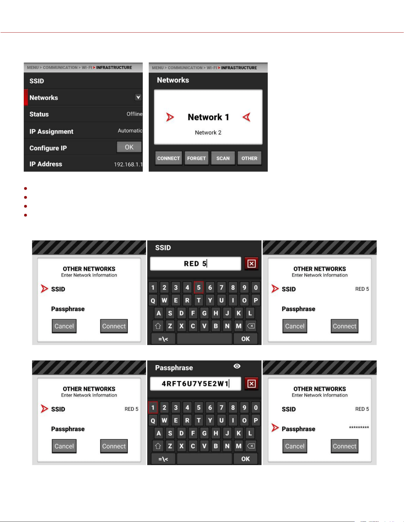
NETWORKS
Use Networks to select an existing network, scan for an available network, or to configure a new network.
CONNECT: The CONNECT button connects the camera to the selected network.
FORGET: The FORGET button erases the connection information for the selected network.
SCAN: The SCAN button searches for available networks.
OTHER: The OTHER button opens the OTHERNETWORKS screen where you can manually enter an SSID and a
Passphrase.
Tap SSID to open the SSID editing screen and enter the desired network SSID:
Tap Passphrase to open the Passphrase editing screen and enter the desired passphrase for the network:
COPYRIGHT © 2023 RED.COM, LLC 955-0218, REV A | 149
KOMODO-X
®
OPERATION GUIDE
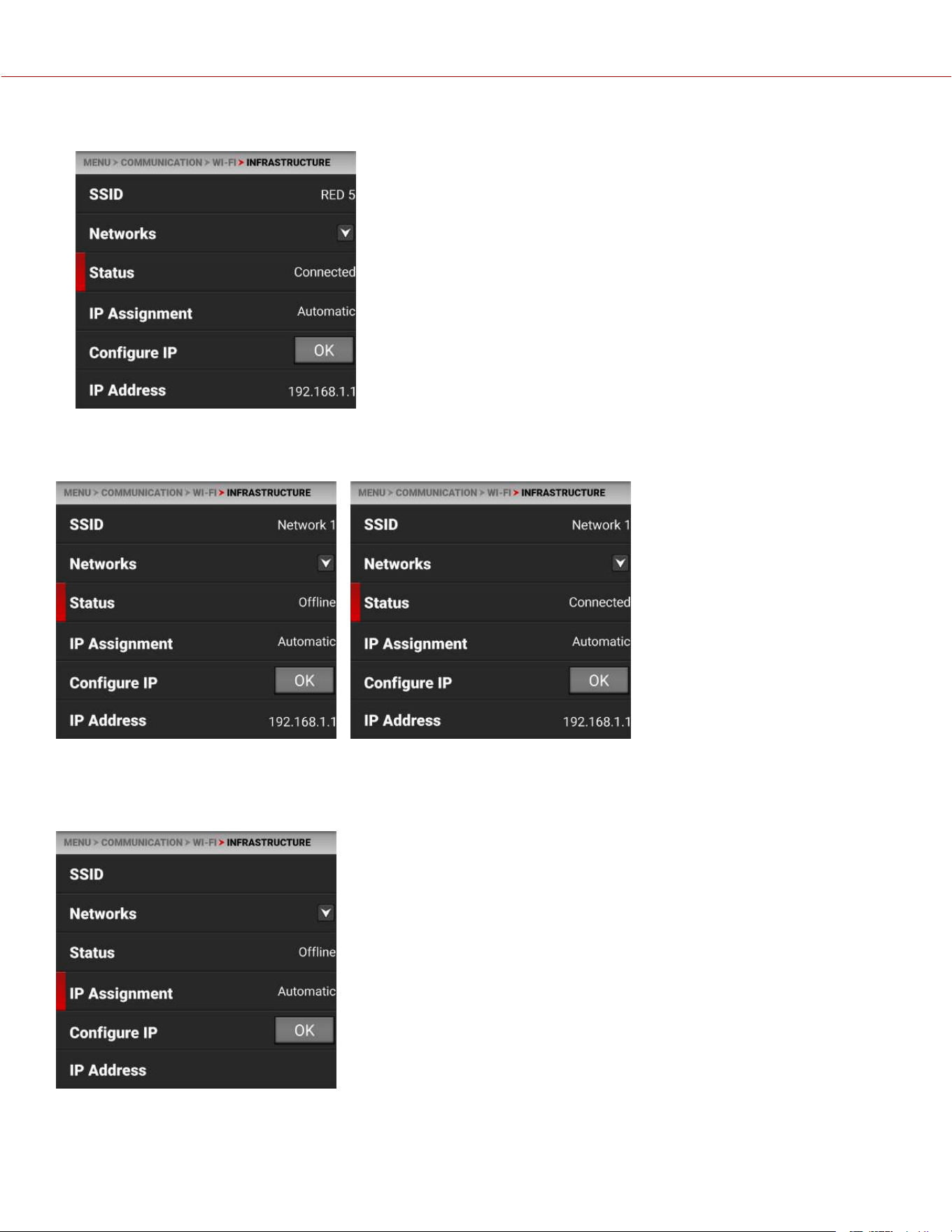
Tap Connect to connect to the new network:
STATUS
Displays the connection status of the camera to the selected Wi-Fi network.
IP ASSIGNMENT
IP Assignment displays the IP assignment mode. In Automatic mode, the camera automatically discovers the
Infrastructure IP Address. In Manual mode, you can manually enter the network addresses in the camera.
COPYRIGHT © 2023 RED.COM, LLC 955-0218, REV A | 150
KOMODO-X
®
OPERATION GUIDE
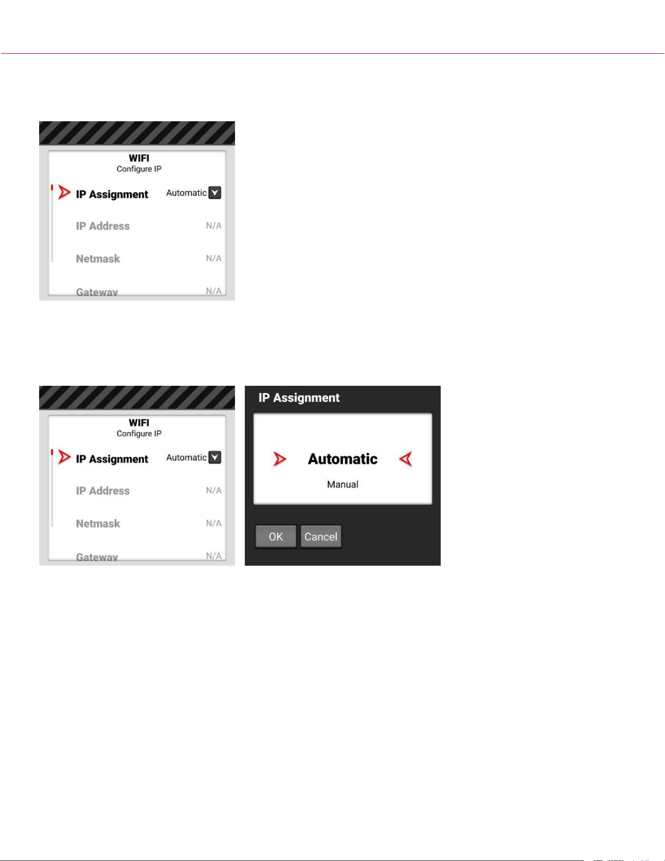
CONFIGURE IP
Tap OK to Open the Infrastructure Configure IP screen.
You use the Configure IP screen to select the IP Assignment mode, and to manually enter the IP, Netmask, and
Gateway addresses in Manual mode.
IP ASSIGNMENT SELECTION
IP Assignment allows you to select the Infrastructure IP Assignment mode.
The Automatic mode detects the available Infrastructure IP address. The Manual mode allows you to manually enter the
desired Infrastructure network addresses.
COPYRIGHT © 2023 RED.COM, LLC 955-0218, REV A | 151
KOMODO-X
®
OPERATION GUIDE

IP ADDRESS
When connected to a Wi-Fi network and Automatic IP Assignment is enabled, IP Address displays the Wi-Fi network IP
address.
When Manual IP Assignment is enabled, you can manually enter a static IP address.
NETMASK
When connected to an Ethernet network and Automatic IP Assignment is enabled, Netmask displays the network
Netmask address.
COPYRIGHT © 2023 RED.COM, LLC 955-0218, REV A | 152
KOMODO-X
®
OPERATION GUIDE
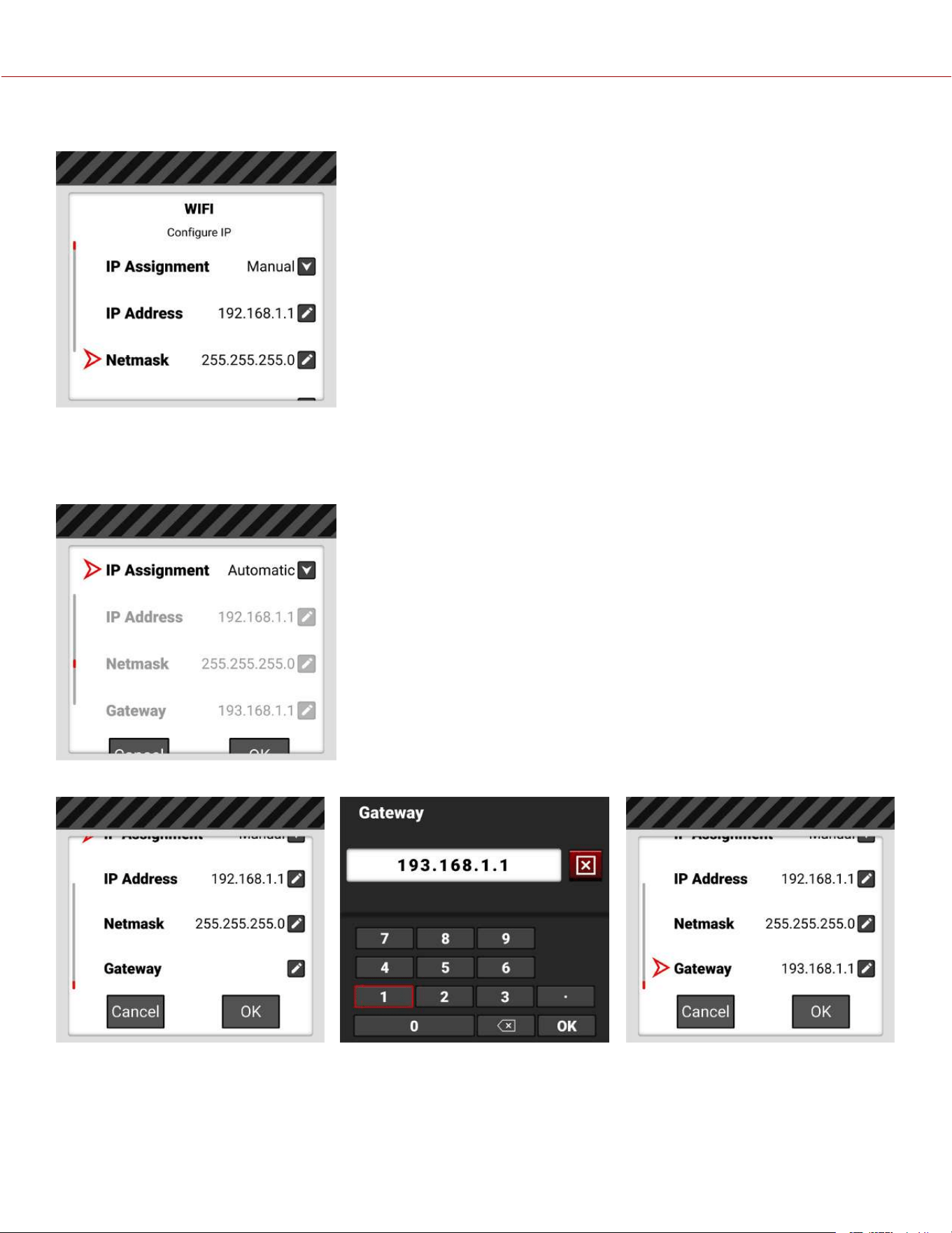
When Manual IP Assignment is enabled, 255.255.255.0 is automatically populated as the Netmask address.
GATEWAY
When connected to a Wi-Fi network and Automatic IP Assignment is enabled, Gateway displays the Wi-Fi network
Gateway address (router address).
When Manual IP Assignment is enabled, you can manually enter a Gateway address.
COPYRIGHT © 2023 RED.COM, LLC 955-0218, REV A | 153
KOMODO-X
®
OPERATION GUIDE
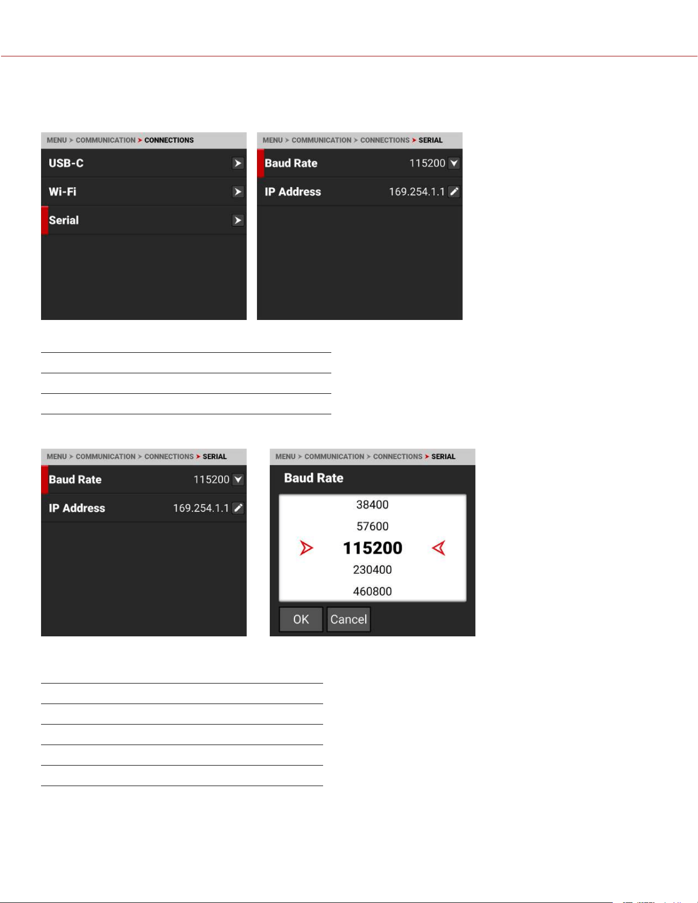
SERIAL
Use Serial to configure the serial connection to the Extension Port.
The settings you can configure for the serial connection through the Extension Port include:
ITEMS DETAILS
Serial Select the serial port baud rate
Serial Enter the IP address for the PPP protocol
BAUD RATE
The Baud rate controls how fast data is transmitted over the serial connection. The higher the speed, the more likely
that errors can occur. The Baud rates you can choose include:
BAUD RATES
9600 115200* 576000 1500000
19200 230400 921600 2000000
38400 460800 1000000 2500000
57600 500000 1152000 3000000
* Default
COPYRIGHT © 2023 RED.COM, LLC 955-0218, REV A | 154
KOMODO-X
®
OPERATION GUIDE
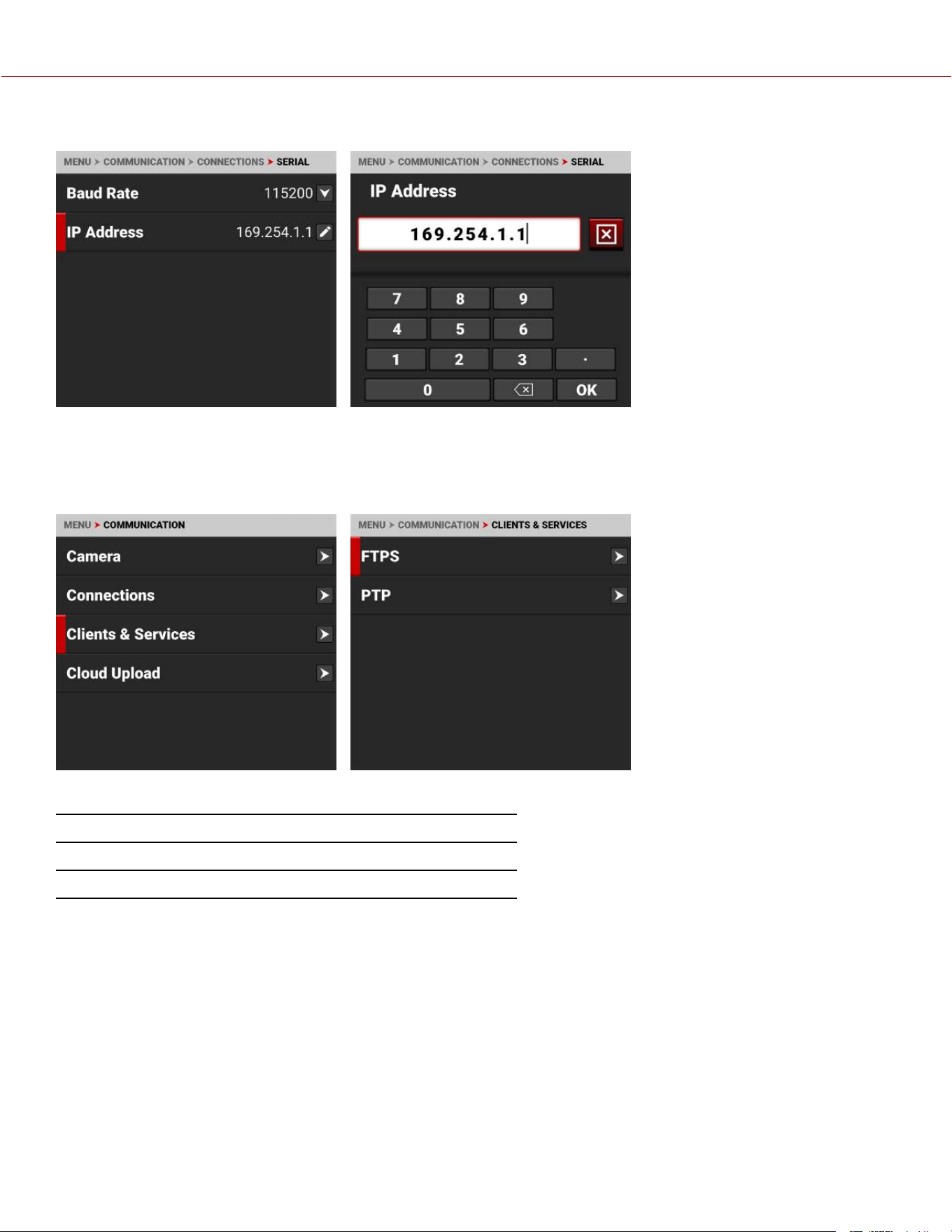
IP ADDRESS
Use the keypad to enter the internet provider's IP address.
CLIENTS & SERVICES
Use the Clients & Services menu to configure the client and service communications for the camera.
Use the Clients & Services menu to configure the camera's client and service settings:
ITEM DETAILS
FTPS Configure the camera FTPS communication settings
PTP Configure the camera PTP communications settings
COPYRIGHT © 2023 RED.COM, LLC 955-0218, REV A | 155
KOMODO-X
®
OPERATION GUIDE
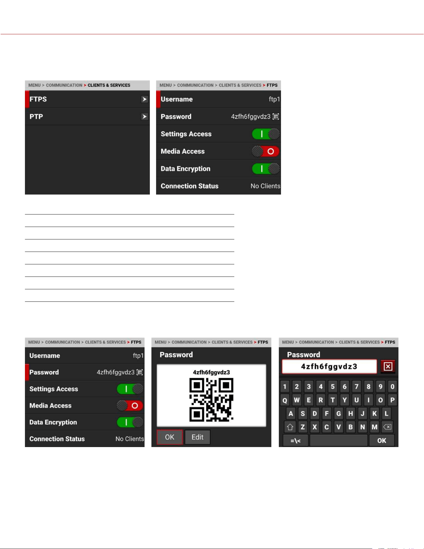
FTPS
Use FTPS to configure the camera to work with a secure File Transfer Protocol (FTPS) connection.
Use the FTPS menu to configure the camera's FTPS settings:
ITEM DETAILS
Username Static username ftp1
Password User-editable password and QR code
Settings Access Enable FTP access to the camera settings
Media Access Enable read-only access to the media
Data Encryption Encrypts the data stream
Connection Status Displays the FTPS actions occurring
PASSWORD
Use Password to enter an FTPS password. When you select Password, the FTPS Password QR code screen appears.
Select EDIT to open the FTPS Password editing screen. The password must contain a minimum of 8 characters. The
screen displays passwords shorter than 8 characters in a red font.
COPYRIGHT © 2023 RED.COM, LLC 955-0218, REV A | 156
KOMODO-X
®
OPERATION GUIDE
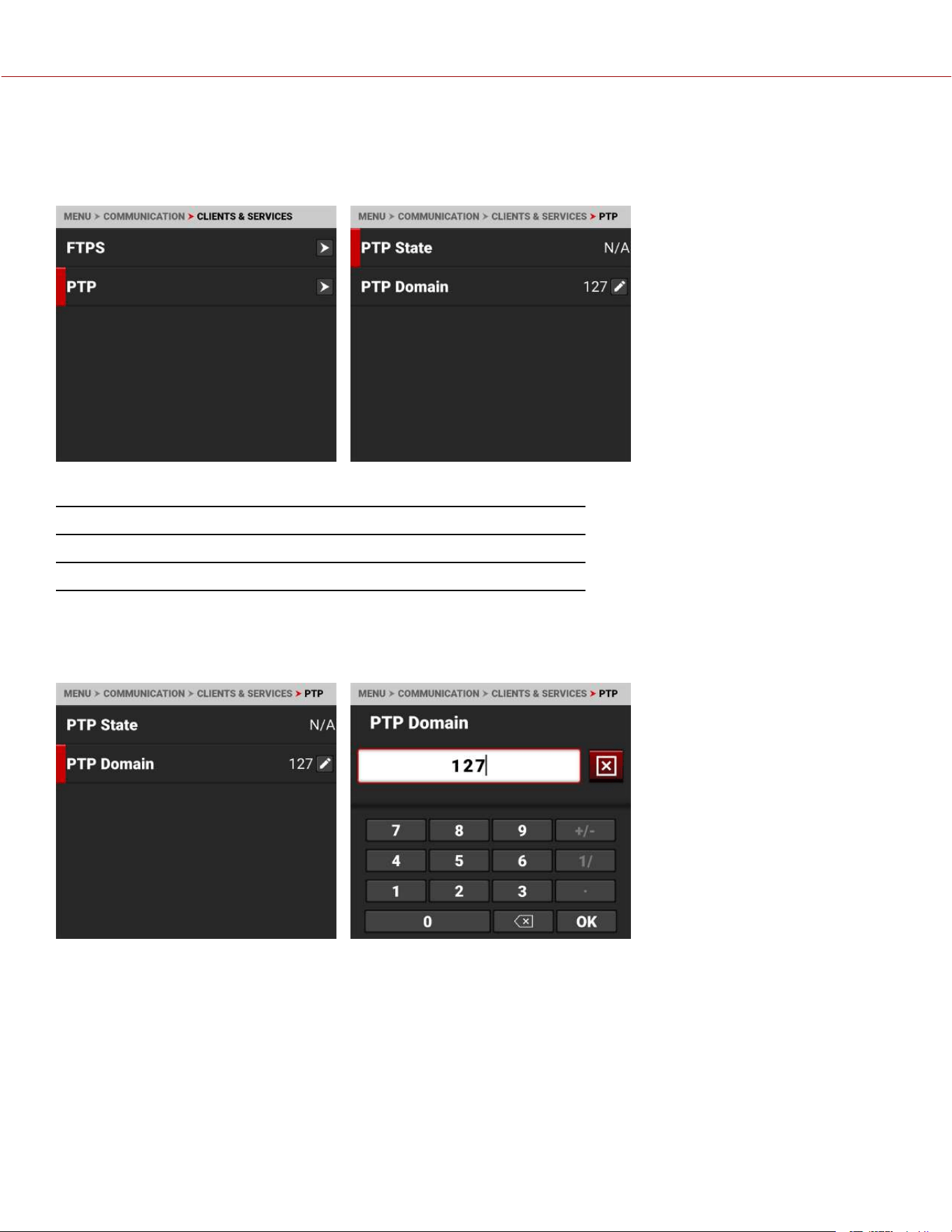
PTP
Use PTP to view the precision time protocol status and configure the precision time protocol IP domain.
Enable PTP in Audio/ TC > Timecode Source (refer to Timecode Source).
The settings you can configure for PTP include:
ITEM DETAILS
PTP State Displays the current status of the precision time protocol
PTP Domain Allows you to select the precision time protocol domain
PTP DOMAIN
Use PTP Domain to select the precision time protocol domain for the camera. The camera will only receive precision
time protocol communications addressed to the selected IP domain.
COPYRIGHT © 2023 RED.COM, LLC 955-0218, REV A | 157
KOMODO-X
®
OPERATION GUIDE
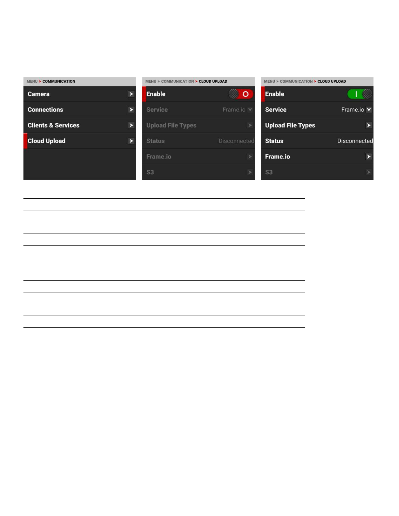
CLOUD UPLOAD
Use the Cloud Upload menu to configure the cloud upload communications for the camera.
Use the Cloud Upload menu to manage the camera's cloud uploading features:
ITEM DETAILS
Enable Enable or disable the Cloud Upload features
Service Select Frame.io or AWS S3 as the cloud upload service
Upload File Types Enable or disable the uploading of R3D, MOV, WAV, and CDL/LUT files
Status Displays the status of the cloud connection
Frame.io Configure the Frame.io settings when this service is selected
S3 Configure the AWS S3 settings when this service is selected
Clips Remaining Displays the number of clips remaining to upload
Time Remaining Displays the time remaining to upload
Upload Remaining Displays the size of the remaining upload
Upload Speed Displays the speed of the upload
COPYRIGHT © 2023 RED.COM, LLC 955-0218, REV A | 158
KOMODO-X
®
OPERATION GUIDE

SERVICE
Use Service to select the type of cloud upload service the camera uses.
The types of cloud upload services you can select for the camera include:
ITEM DETAILS
Frame.io Selects the Frame.io cloud collaboration service
S3 Selects the AWS S3 cloud data management service
UPLOAD FILE TYPES
Use Upload File Types to select the file types you want the camera to upload to the cloud.
The Upload File Types menu only allows you to enable the file types avalable on the camera. When they are not on the
camera they are grayed-out on the menu.
The Upload File Types you can select include:
ITEM DETAILS
R3D REDCODE RAW video file format
MOV ProRes video file
WAV Standard Waveform audio data file
CDL/LUT In camera CDL and LUT files
COPYRIGHT © 2023 RED.COM, LLC 955-0218, REV A | 159
KOMODO-X
®
OPERATION GUIDE
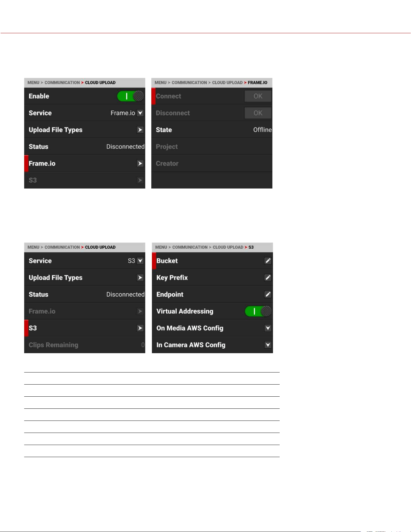
FRAME.IO
Use Frame.io to connect to, and disconnect from, your Frame.io project.
When you select Connect, the screen displays a time sensitive 6-digit code. Use this code to sync the camera to the
desired project on the Frame.io website.
S3
Use S3 to configure the camera S3 communications.
The S3 communications setting you can configure include:
ITEM DETAILS
Bucket Enter the S3 Bucket name
Key Prefix Enter the S3 Key Prefix (optional)
Endpoint Override the the default S3 Endpoint address (optional)
Virtual Addressing Enable or disable Virtual Addressing
On Media AWS Config Select the AWS configuration stored on the media
In Camera AWS Config Manage the AWS configurations saved to the camera
COPYRIGHT © 2023 RED.COM, LLC 955-0218, REV A | 160
KOMODO-X
®
OPERATION GUIDE
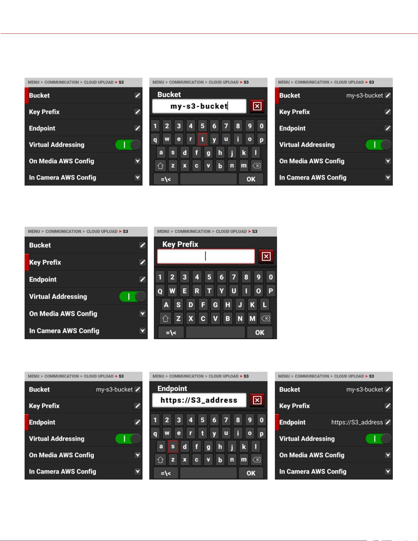
BUCKET
Use Bucket to enter the name of the S3 Bucket you want to use to upload your data to the cloud.
KEY PREFIX
When specified, the camera adds a prefix to the key (or path) of the uploaded objects to create a subfolder in the
bucket (optional).
ENDPOINT
Use Endpoint to override the default S3 endpoint address (optional).
VIRTUAL ADDRESSING
Virtual Addressing is typically enabled. However, you must disable it when interfacing with some S3-compatible storage.
Contact your S3 administrator for more information.
COPYRIGHT © 2023 RED.COM, LLC 955-0218, REV A | 161
KOMODO-X
®
OPERATION GUIDE
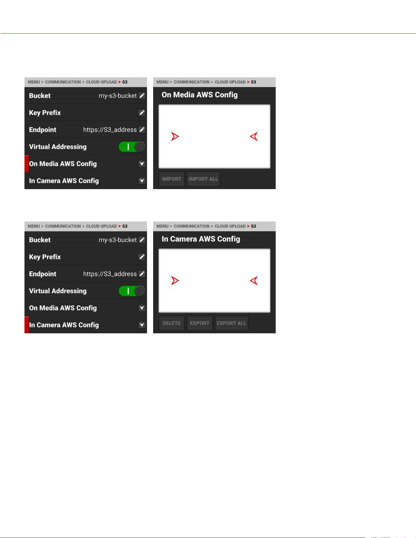
ON MEDIA AWS CONFIG
Use On Media AWS Config to select an AWS configuration stored on the media card in the aws folder (/aws).
IN CAMERA AWS CONFIG
Use In Camera AWS Config to export or delete AWS configurations stored on the camera.
AWS Configuration and Credentials files contain important information for connecting to the AWS bucket, such as
region, and access ID / key. AWS CLI tools generate these files when you enter "aws configure". You can also create
AWS Configuration and Credentials files manually.
Examples of the AWS configuration and credentials files:
config:
[default]
region = us-west-2
credentials:
[default]
aws_access_key_id = AKIAIOSFODNN7EXAMPLE
aws_secret_access_key = wJalrXUtnFEMI/K7MDENG/bPxRfiCYEXAMPLEKEY
COPYRIGHT © 2023 RED.COM, LLC 955-0218, REV A | 162
KOMODO-X
®
OPERATION GUIDE
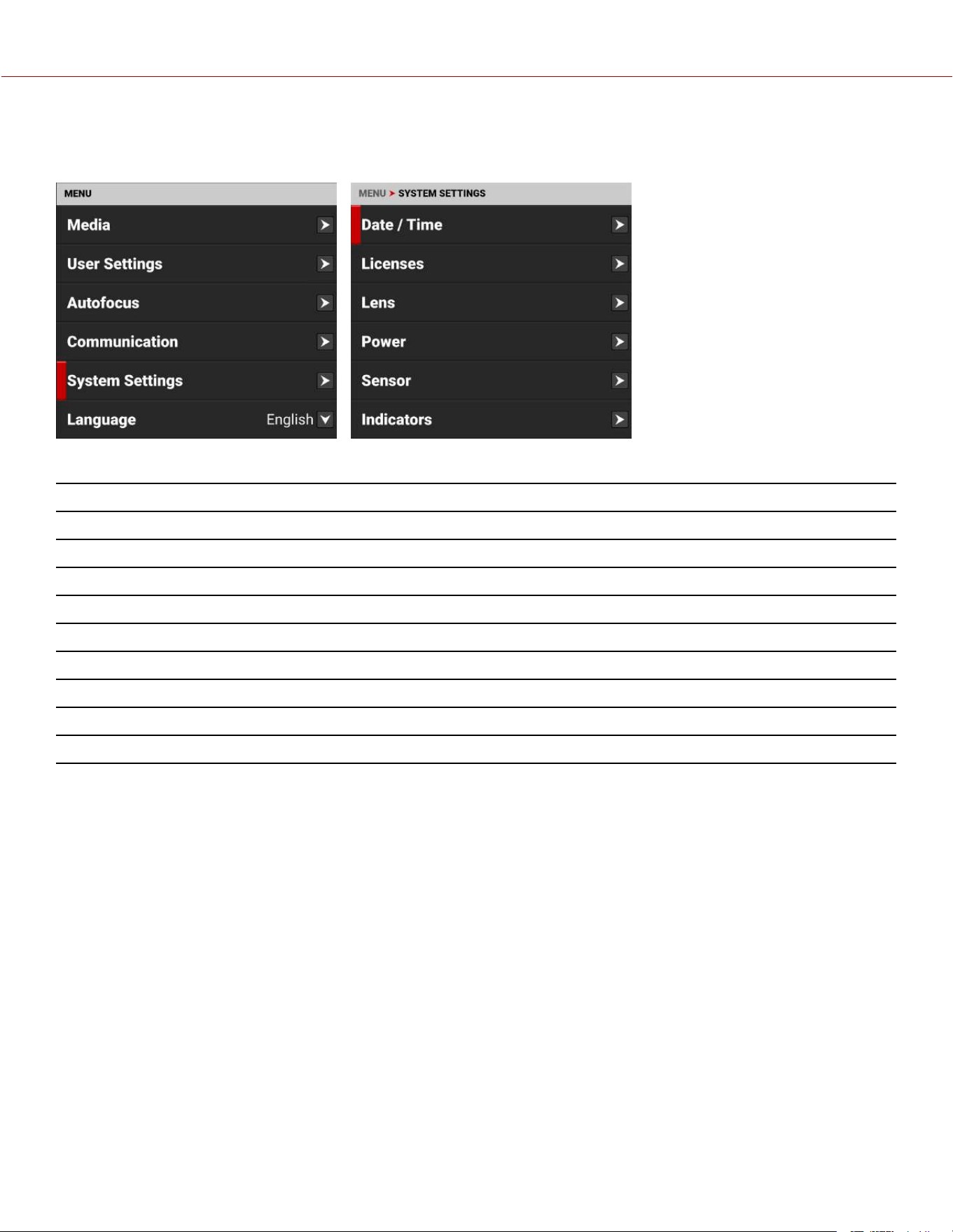
SYSTEM SETTINGS MENU
The System Settings menu contains the camera system configuration settings.
Use the System Settings menu to configure the camera system settings:
ITEMS DETAILS
Date / Time Date and time settings
Licenses Manage camera licenses
Lens View lens status information and access the lens adjustments
Power DC and battery status
Sensor Adjust sensor timing
Indicators Enable or disable the record sounds and the front Tally LED
GPO Function Select Sync Out function
Status Settings Shutter mode, aperture increments, and focus length units settings
System Status Information about the camera's type, PIN, FW, and runtime
COPYRIGHT © 2023 RED.COM, LLC 955-0218, REV A | 163
KOMODO-X
®
OPERATION GUIDE
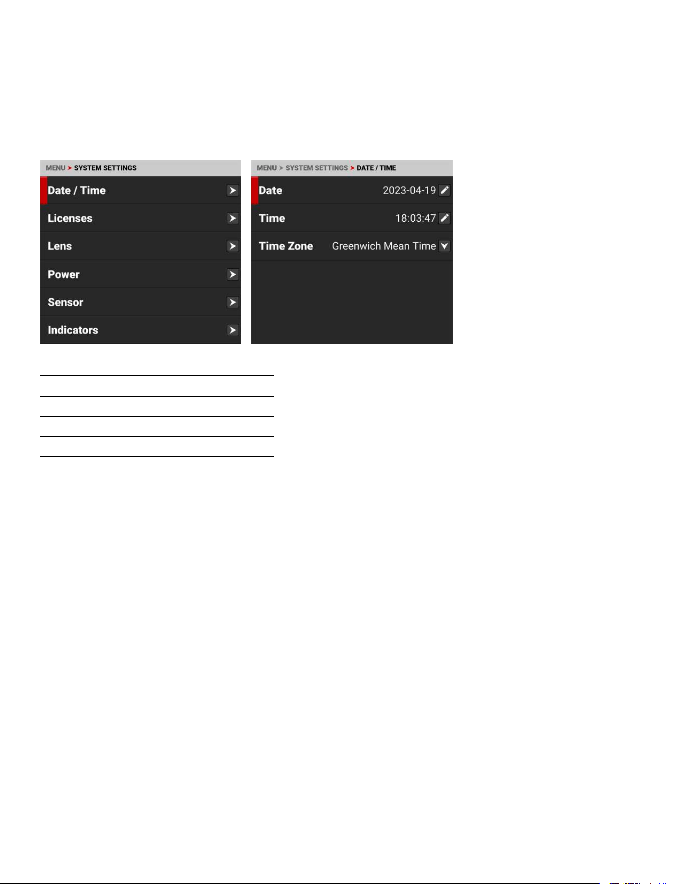
DATE / TIME
Use the Date / Time menu to reset the internal clock of the camera. The time and date are timestamped on R3D
®
files
when recording to the media. The camera uses the 24-hour clock convention (military time). For example, enter 2:35
p.m. as 14:35:00.
The Date / Time menu items include:
ITEMS DETAILS
Date Date in YYYY-MM-DD format
Time 24-hour format
Time Zone Global time zones
COPYRIGHT © 2023 RED.COM, LLC 955-0218, REV A | 164
KOMODO-X
®
OPERATION GUIDE
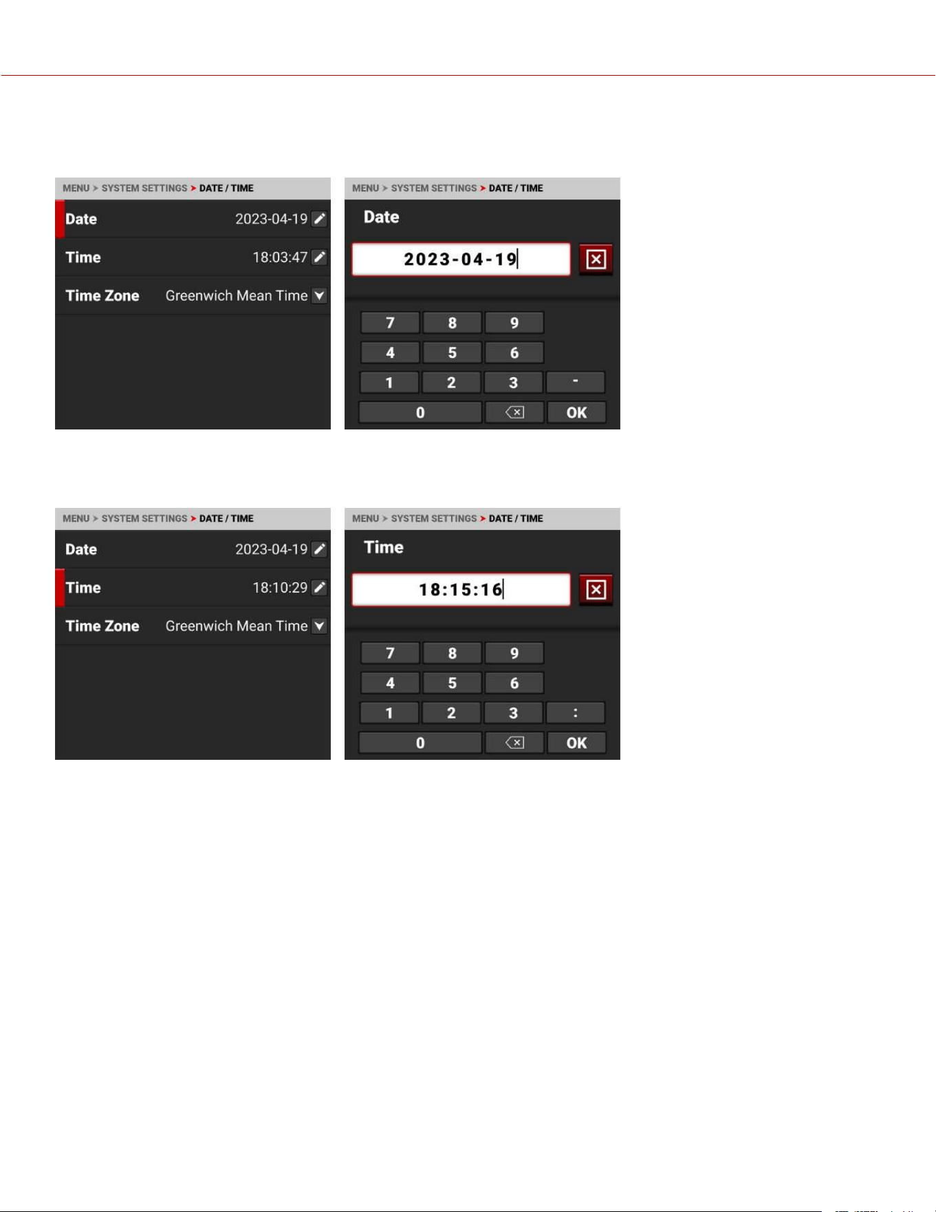
DATE
Use Date to enter the date using the touchscreen keypad:
TIME
Use Time to enter the time in 24-hour military format using the touchscreen keypad:
COPYRIGHT © 2023 RED.COM, LLC 955-0218, REV A | 165
KOMODO-X
®
OPERATION GUIDE
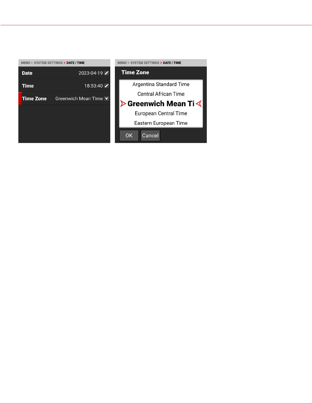
TIME ZONE
Use Time Zone to select the local time zone for where the camera is located.
COPYRIGHT © 2023 RED.COM, LLC 955-0218, REV A | 166
KOMODO-X
®
OPERATION GUIDE
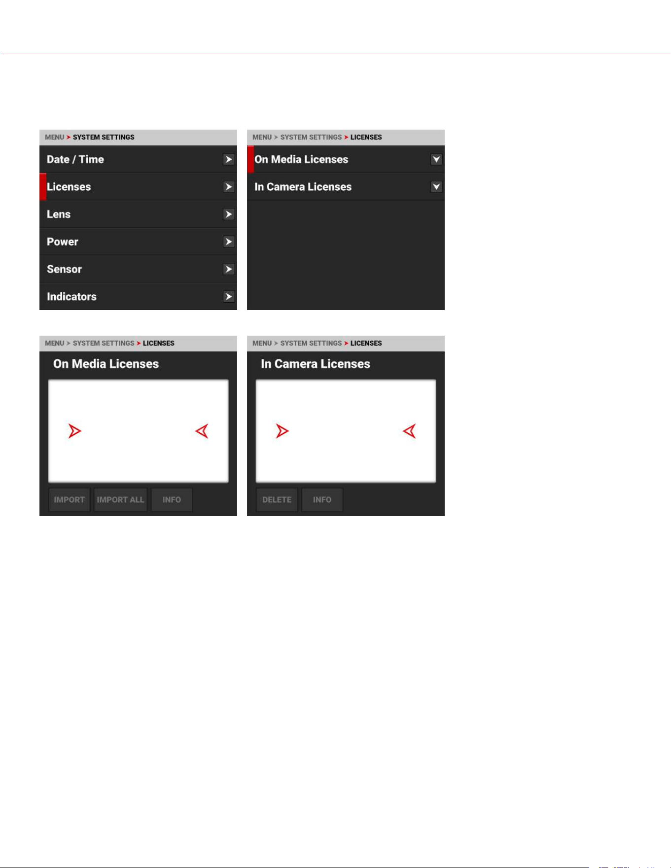
LICENSES
Use the Licenses menu to manage your RED camera licenses.
You can manage the licenses stored on the media card, and you can manage the licenses stored in the camera.
COPYRIGHT © 2023 RED.COM, LLC 955-0218, REV A | 167
KOMODO-X
®
OPERATION GUIDE
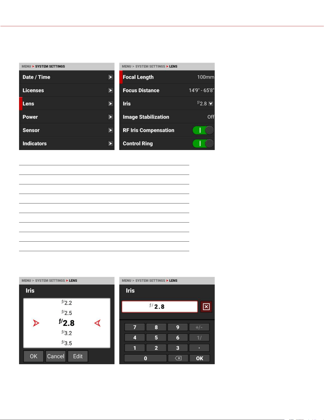
LENS
Use Lens to view information about the attached lens.
The information you can view from Lens includes:
ITEMS DETAILS
Focal Length Displays the lens focal length value
Focus Distance Displays the lens focal distance value
Iris Lens Iris menu
Image Stabilization Displays the lens image stabilization status
RF Iris Compensation Enables RF Iris Compensation
Control Ring Enables the lens control ring
Control Ring Mode Control Ring Mode settings
/i Data View the PL mount lens /i Data information
IRIS
Use the Iris menu to select the camera lens f-stop. Tap Edit to open the keypad and enter the f-stop manually.
COPYRIGHT © 2023 RED.COM, LLC 955-0218, REV A | 168
KOMODO-X
®
OPERATION GUIDE
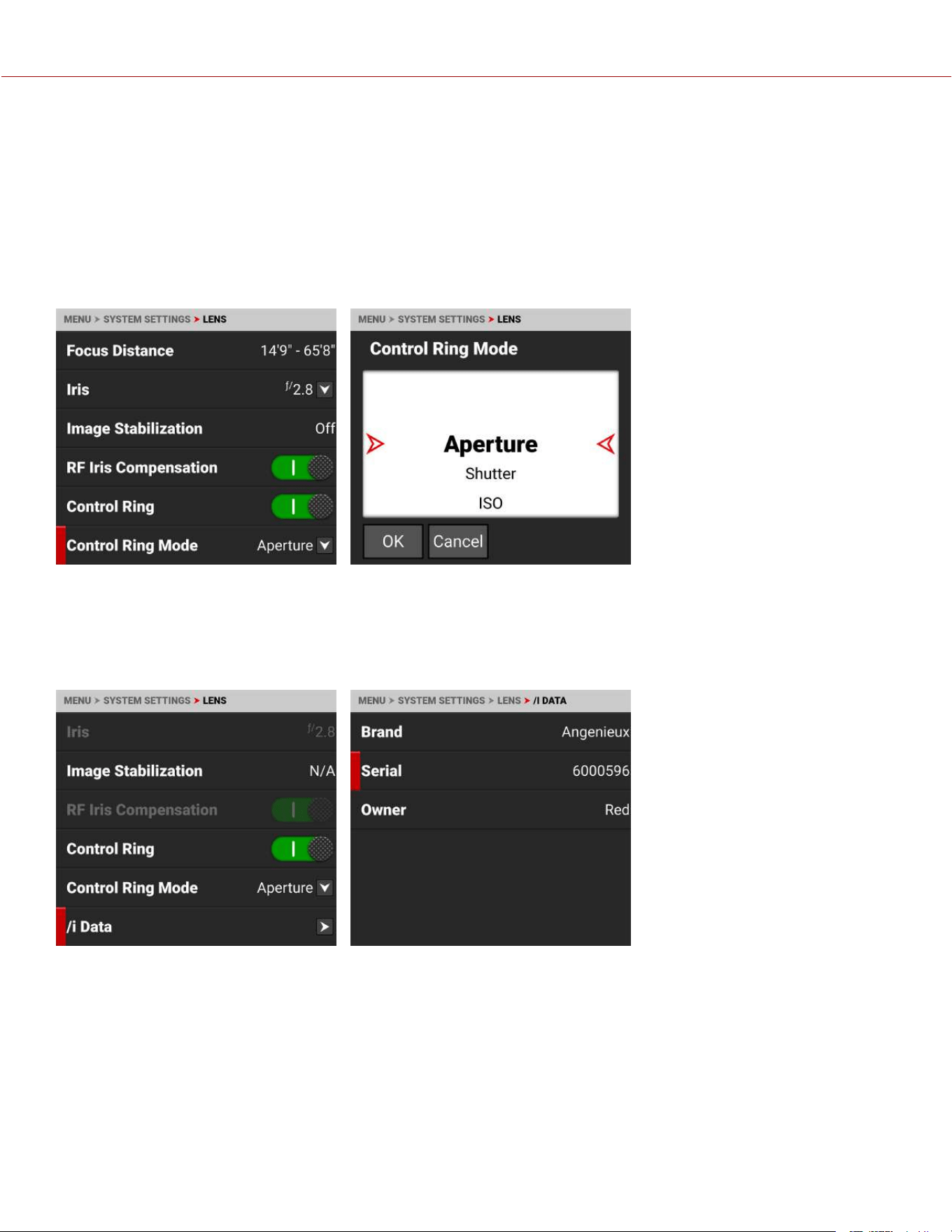
RF IRIS COMPENSATION
Use RF Iris Compensation to compensate for iris position shifting that can occur with certain RF zoom lenses as you
change the focal length. This compensation keeps the iris reasonably maintained when the focal length is changed after
you set the iris. When enabled, a small iris fluttering may be visible during zooming. You can disable RF Iris
Compensation to stop the iris fluttering.
CONTROL RING MODE
Use Control Ring Mode to select the camera setting you want the Control Ring to adjust.
The modes you can select include Aperture (Iris, default), Shutter, ISO, White Balance, LCD Magnify, SDI Magnify, LCDs
+ SDI Magnify, False Color Cycle, Peaking Cycle, and Tools Cycle.
/i DATA
Use /i Data to view the PL mount lens /i Data information.
You can view the lens Brand, Serial number, and Owner name.
COPYRIGHT © 2023 RED.COM, LLC 955-0218, REV A | 169
KOMODO-X
®
OPERATION GUIDE
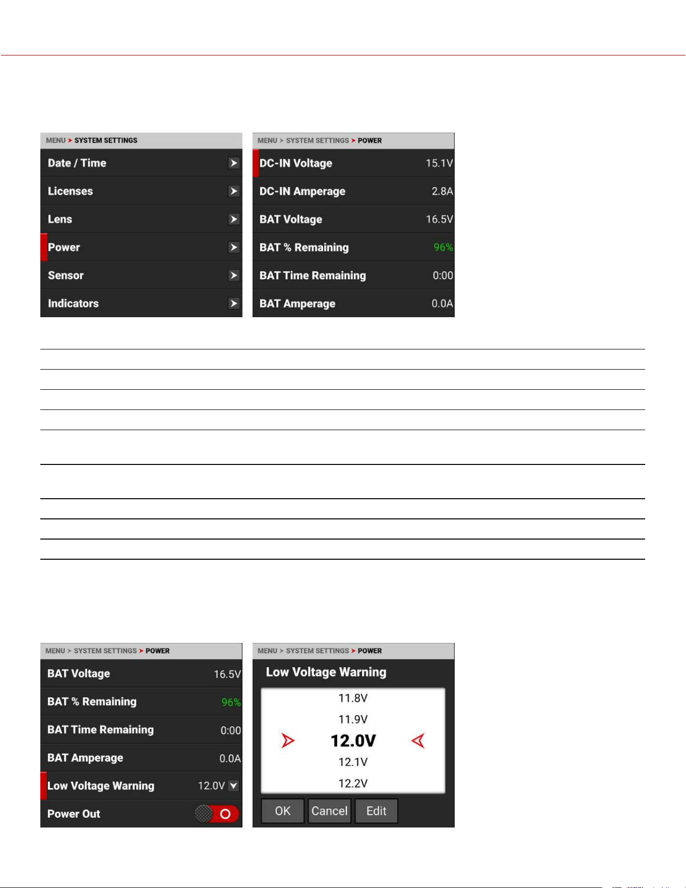
POWER
Use the Power menu to view the various camera power status indicators:
The Power indicators you can view include:
ITEMS DETAILS
DC-IN Voltage When DC is connected, this displays the DC Voltage
DC-IN Amperage When DC is connected, this displays the DC Amps
BAT Voltage When a battery is connected in the left #1 slot, this displays the battery Voltage
BAT % Remaining When a compatible battery is connected in the left #1 slot, this displays the % of battery
charge remaining
BAT Time Remaining When a battery is connected in the left #1 slot, this displays the camera operating time
remaining
BAT Amperage When a battery is connected in the left #1 slot, this displays the battery Amps
Low Voltage Warning Set the battery low voltage warning threshold
Power Out Enables or disables the 5 V / 500 mA power out of the Extension Port
LOW VOLTAGE WARNING
Use Low Voltage Warning to set the desired voltage level to trigger the low voltage warning. The warning displays on
the LCD and across Overlay Modes that contain battery status (refer to the Status Bar section for more information
about the status icons).
COPYRIGHT © 2023 RED.COM, LLC 955-0218, REV A | 170
KOMODO-X
®
OPERATION GUIDE
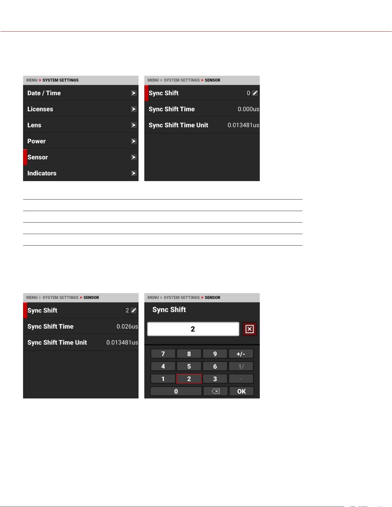
SENSOR
Use Sensor to shift the sync signal.
The Sensor menu includes:
ITEM DETAILS
Sync Shift Enter the desired amount of sync shift
Sync Shift Time Displays the Sync Shift time in microseconds (μs)
Sync Shift Time Unit Displays the units of microseconds (μs) used for the Sync Shift setting
SYNC SHIFT
Use Sync Shift to open the keypad and enter the number of Sync Shift Time Units you want to offset the sensor from
the external sync signal. Use this setting to resolve synchronization issues on set such as when working with LED
Volumes.
In this example, the Sync Shift is 2 x 0.013481 microseconds ≃ 0.026 microseconds.
COPYRIGHT © 2023 RED.COM, LLC 955-0218, REV A | 171
KOMODO-X
®
OPERATION GUIDE
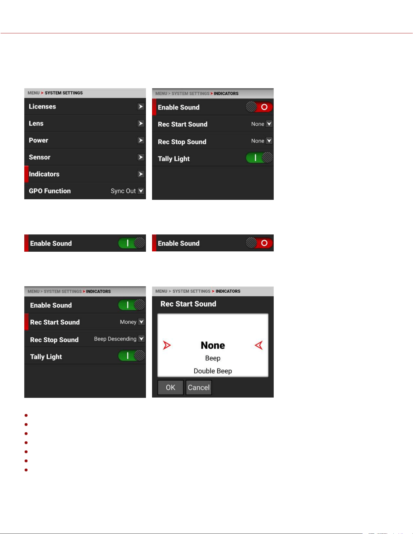
INDICATORS
Use the Indicators menu to enable or disable sound and the tally light (refer to the Camera Body section for more
information about the camera LEDs), and to select the record start indicator and record stop indicator sounds.
ENABLE SOUND
Use Enable Sound to allow the selected sounds to play.
REC START SOUND
Rec Start Sound allows you to select the sound to play when you begin a recording.
The sounds you can select include:
None
Beep
Double Beep
Beep Ascending
Beep Descending
Money
Shutter
COPYRIGHT © 2023 RED.COM, LLC 955-0218, REV A | 172
KOMODO-X
®
OPERATION GUIDE
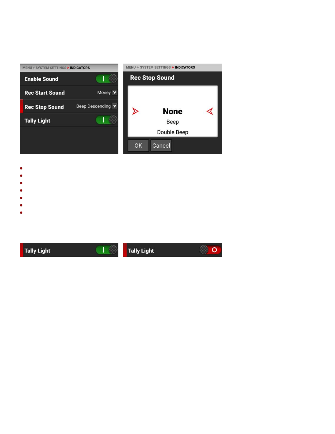
REC STOP SOUND
Rec Stop Sound allows you to select the sound to play when you end a recording.
The sounds you can select include:
None
Beep
Double Beep
Beep Ascending
Beep Descending
Money
Shutter
TALLY LIGHT
Use Tally Light to enable or disable the front recording tally LED.
For more information, refer to the Camera Body LED section.
COPYRIGHT © 2023 RED.COM, LLC 955-0218, REV A | 173
KOMODO-X
®
OPERATION GUIDE
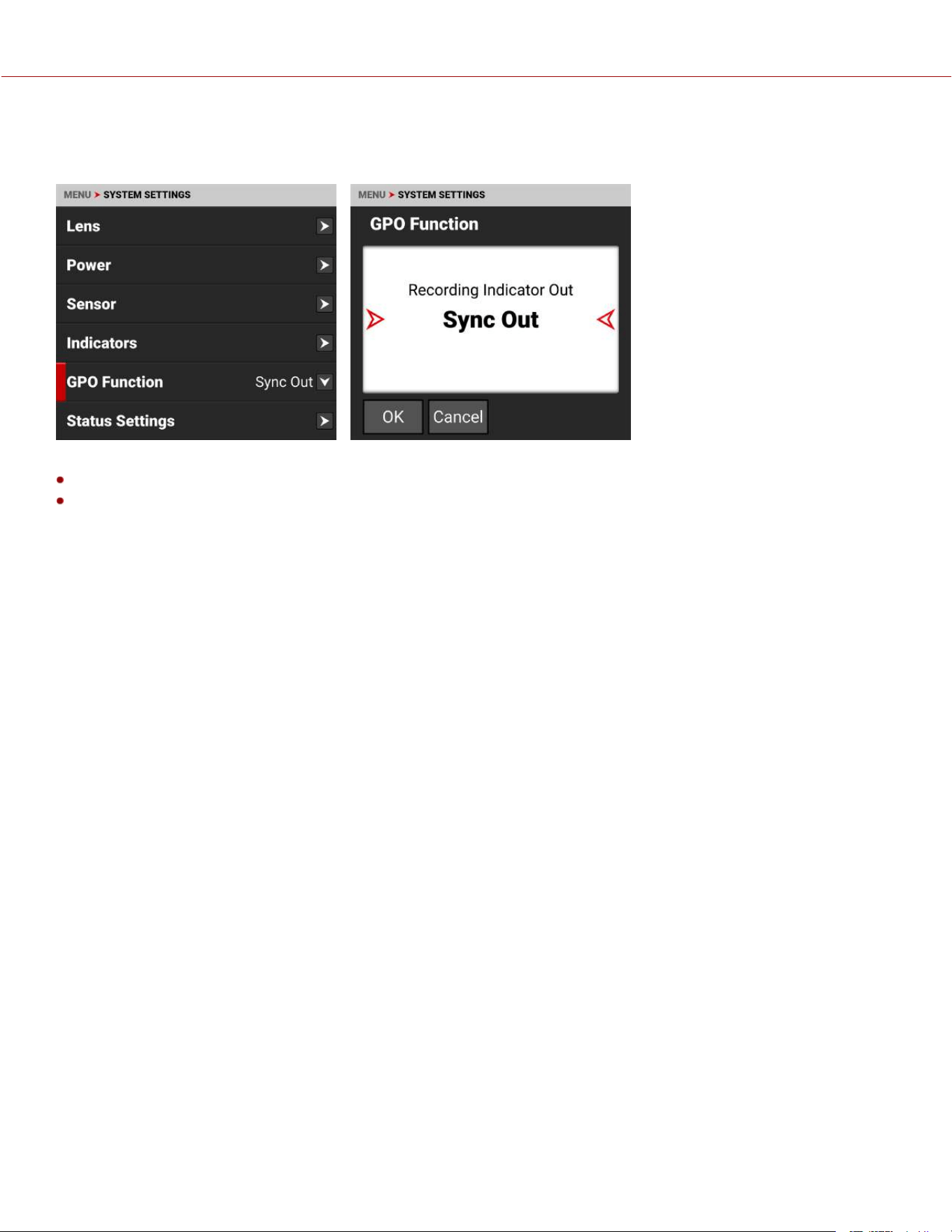
GPO FUNCTION
Use the GPO Function menu to select the GPO function of the Extension port.
You can select the following GPO functions for the Extension port:
Recording Indicator Out
Sync Out
RECORDING INDICATOR OUT
The Recording Indicator Out function sends a signal out of the Extension port GPO pin when the camera is recording.
SYNC OUT
The Sync Out function sends a Sync signal out of the Extension port GPO pin.
For more information, refer to Extension Port.
COPYRIGHT © 2023 RED.COM, LLC 955-0218, REV A | 174
KOMODO-X
®
OPERATION GUIDE
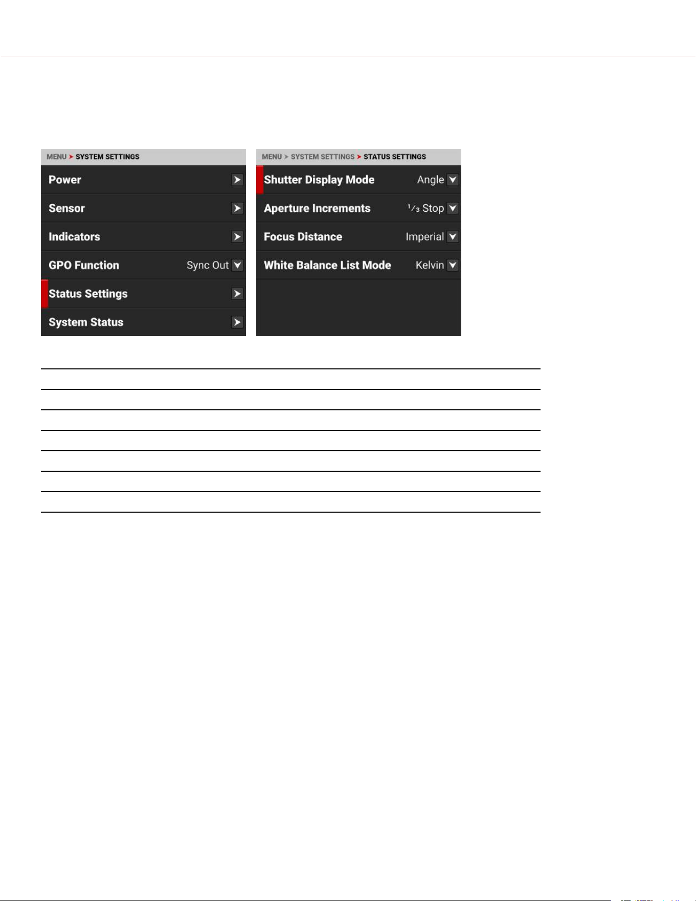
STATUS SETTINGS
Use the Status Settings menu to select the shutter display mode, aperture increment, and focus distance units
displayed in the camera's menus.
The Status Settings that you can configure include:
ITEMS DETAILS
Shutter Display Mode Select a time-fraction or an angle for the shutter menu display unit
Aperture Increments Select 1/4 or 1/3 f-stop increments
Focus Distance Select the focus distance units (Metric or Imperial)
White Balance List Mode Select Kelvin or White Balance Presets
ND Display Mode When attached, select ND filter Stops or Density display modes
ND Increments When attached, select the ND increment size
COPYRIGHT © 2023 RED.COM, LLC 955-0218, REV A | 175
KOMODO-X
®
OPERATION GUIDE
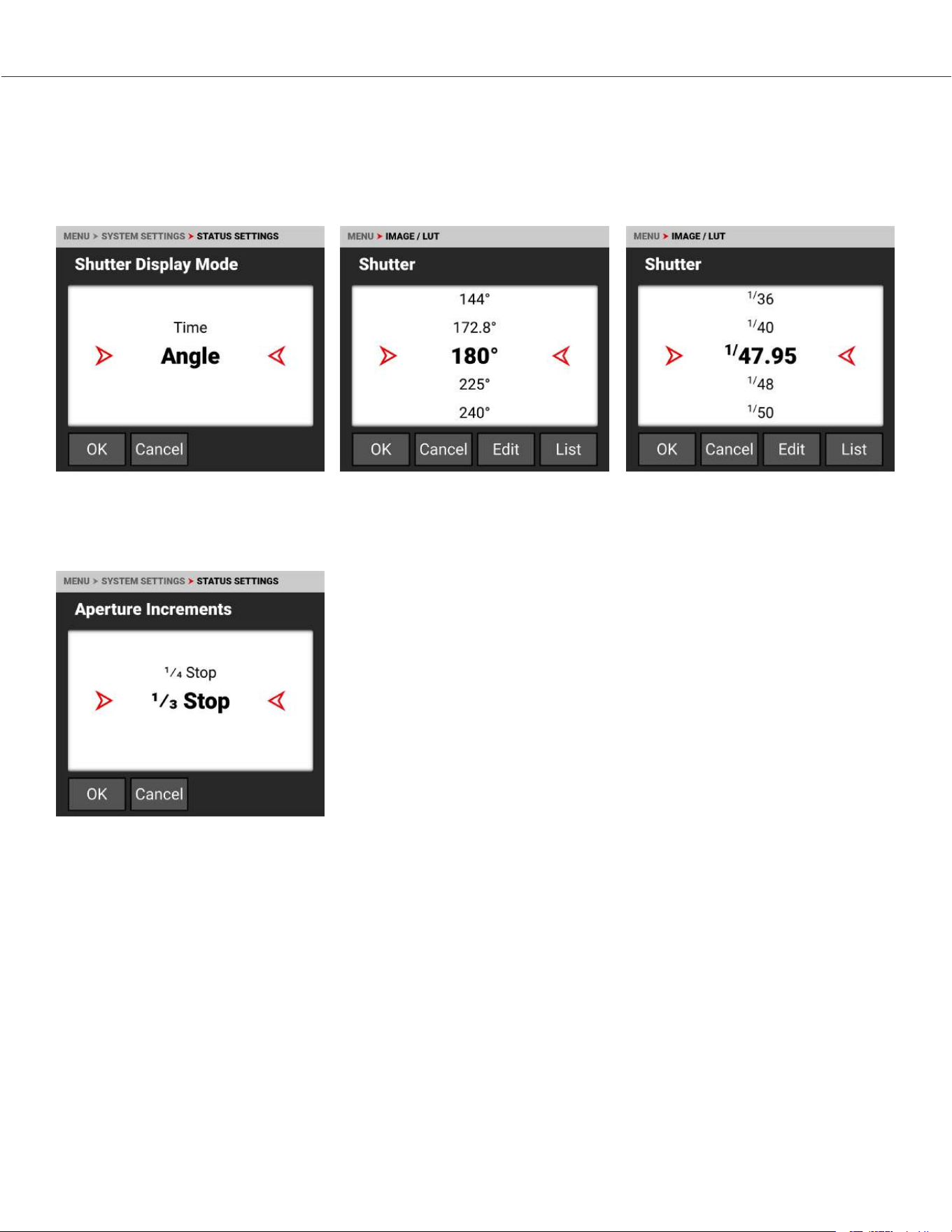
SHUTTER DISPLAY MODE
Use Shutter Display mode to select the way that the camera displays the Shutter setting in the menu.
When select Angle, the Shutter menu displays the choices in degrees. When you select Time, the Shutter menu displays
the choices in fractions of a second.
APERTURE INCREMENTS
Use Aperture Increments to select one fourth increments or one third increments for the camera f-stop settings. The
default is 1/3 Stop.
COPYRIGHT © 2023 RED.COM, LLC 955-0218, REV A | 176
KOMODO-X
®
OPERATION GUIDE
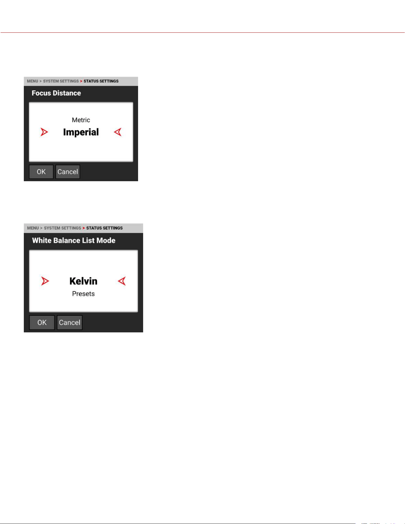
FOCUS DISTANCE
Use Focus Distance to select Imperial or Metric units for the Lens Focus Distance display. The default is Imperial.
WHITE BALANCE LIST MODE
Use White Balance List Mode to select Kelvin or Presets for the White Balance Color Temperature menu. The default is
Kelvin.
COPYRIGHT © 2023 RED.COM, LLC 955-0218, REV A | 177
KOMODO-X
®
OPERATION GUIDE
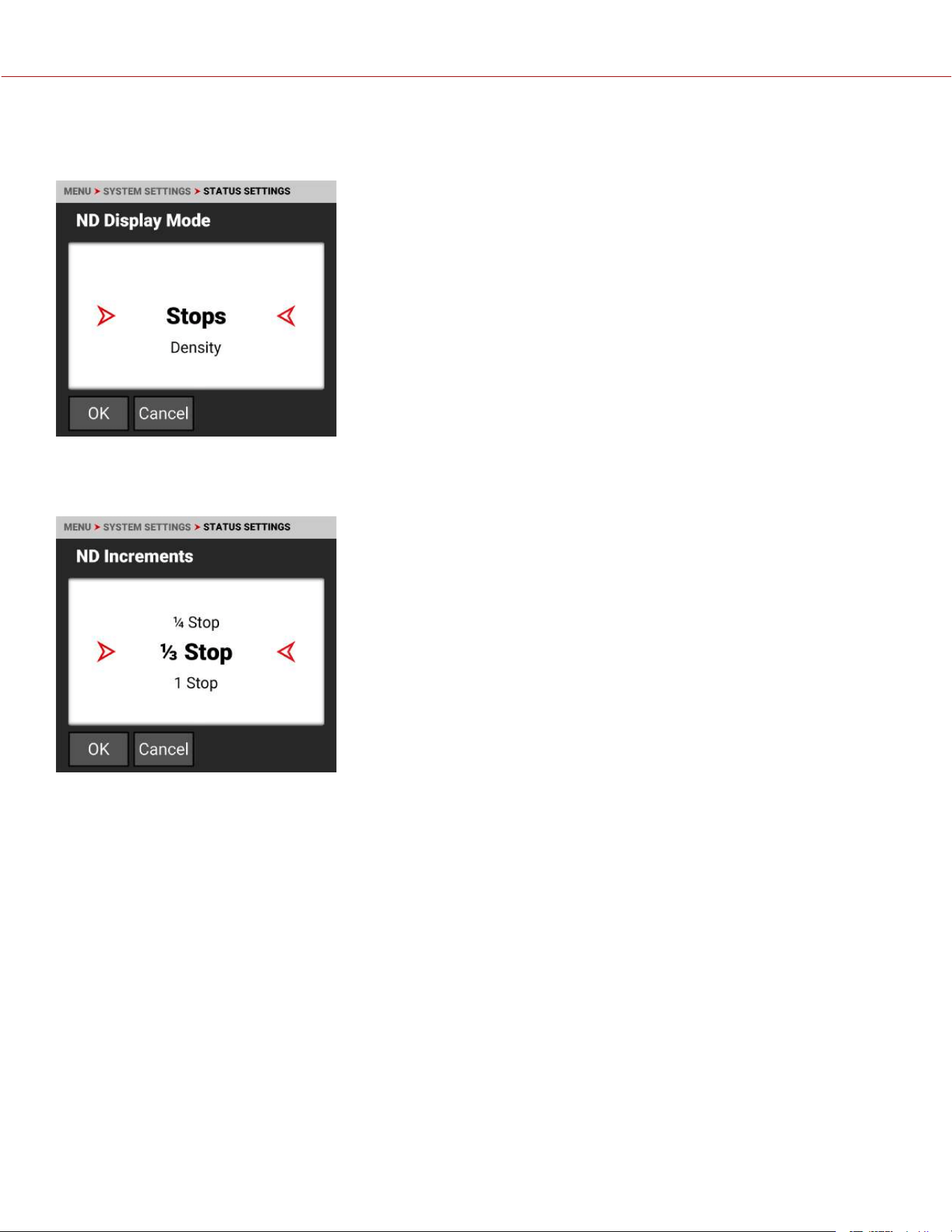
ND DISPLAY MODE
Use ND Display Mode to select Stops or Density display modes when displaying ND settings.
ND INCREMENTS
Use ND Increments to set the increment size for increasing or decreasing the ND stop.
COPYRIGHT © 2023 RED.COM, LLC 955-0218, REV A | 178
KOMODO-X
®
OPERATION GUIDE
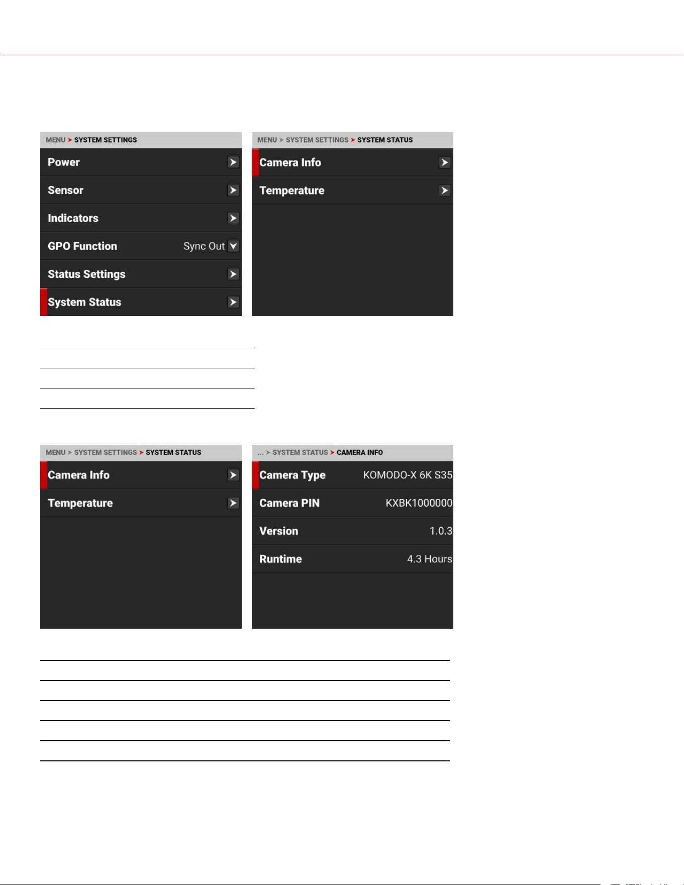
SYSTEM STATUS
Use the System Status menu to view camera information and to view temperature readings.
The system status information you can view includes:
ITEMS DETAILS
Camera Info Camera information
Temperature Camera temperatures
CAMERA INFO
The camera information you can view includes:
ITEMS DETAILS
Camera Type Displays the camera description
Camera PIN Displays the camera personal identification number (PIN)
Version Displays the firmware version number installed on the camera
Runtime Displays the total number of hours that the camera has run
COPYRIGHT © 2023 RED.COM, LLC 955-0218, REV A | 179
KOMODO-X
®
OPERATION GUIDE
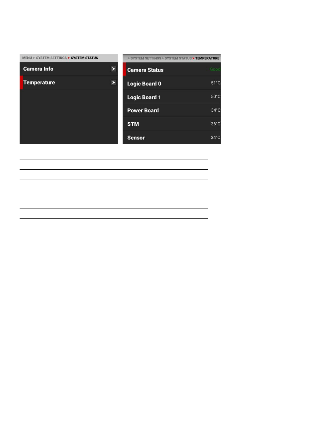
TEMPERATURE
The camera temperatures you can view include:
ITEMS DETAILS
Camera Status Displays Good (green) or Overheating (yellow)
Logic Board 0 Displays the Celsius temperature of Logic Board 0
Logic Board 1 Displays the Celsius temperature of Logic Board 1
Power Board Displays the Celsius temperature of the power IC board
STM Displays the Celsius temperature of the power STM IC
Sensor Displays the Celsius temperature of the sensor
COPYRIGHT © 2023 RED.COM, LLC 955-0218, REV A | 180
KOMODO-X
®
OPERATION GUIDE
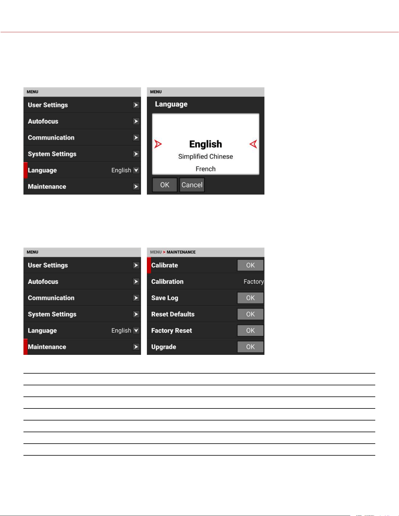
LANGUAGE MENU
The Language menu contains the languages you can select for the user interface (UI).
From the Onboard LCD touchscreen menu, tap Language:
The languages you can select
include:
• English
• Simplified Chinese
• French
• German
• Japanese
• Spanish
MAINTENANCE MENU
The Maintenance menu contains the settings you use to perform various maintenance tasks on your camera.
From the Onboard LCD touchscreen menu, tap Maintenance:
Use the Maintenance menu to perform the following camera maintenance tasks:
ITEM DETAILS
Calibrate Performs calibration
Calibration List of calibration options
Save Log Saves the camera log files to the media
Reset Defaults Resets the camera settings to their default settings
Factory Reset Restores the camera to the factory settings
Upgrade Updates the firmware
COPYRIGHT © 2023 RED.COM, LLC 955-0218, REV A | 181
KOMODO-X
®
OPERATION GUIDE
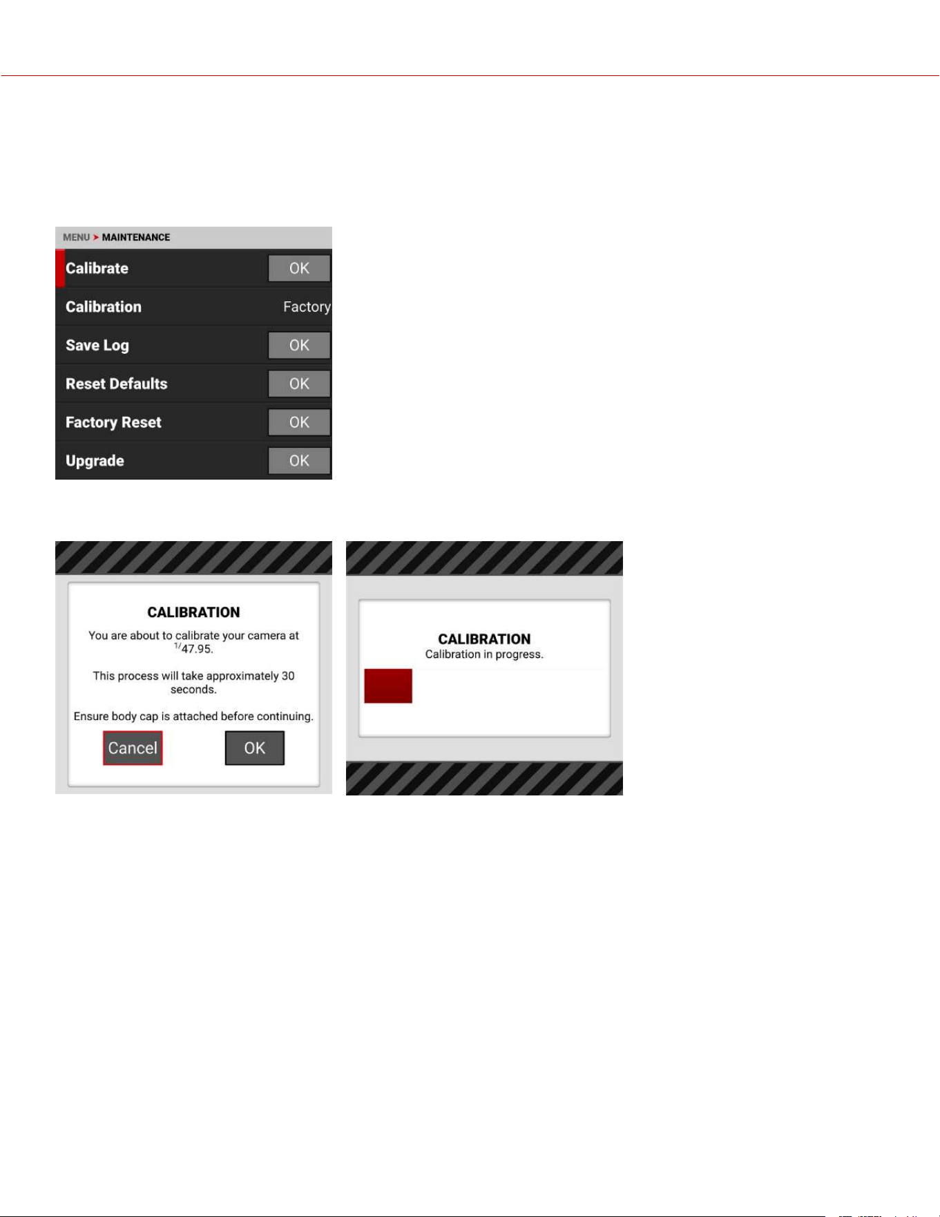
CALIBRATE
Use Calibrate to start the camera calibration process and create your User calibration profile.
Only calibrate the camera after it has reached its operational temperature. This occurs usually within ten minutes after
you turn on the camera in the filming environment. Do not calibrate immediately after powering on.
NOTE: Make sure that the mount cap is installed on the camera before you calibrate the camera.
Tap OK on the touchscreen to begin calibrating the camera.
COPYRIGHT © 2023 RED.COM, LLC 955-0218, REV A | 182
KOMODO-X
®
OPERATION GUIDE
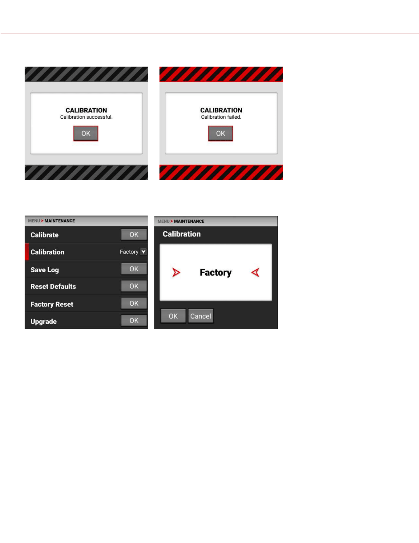
When the camera is finished calibrating, the touchscreen displays the Calibration status message:
or:
CALIBRATION
Use Calibration to select the active camera Calibration.
You should always select User calibration. The first time you calibrate the camera, the only choice is Factory. After you
perform a calibration, the User calibration profile is added to the list and the camera makes it the default calibration.
Every time you calibrate the camera, the User profile is updated. The only time the User profile is removed, is when you
perform a Factory Reset.
If User calibration is not available, the camera defaults to Factory calibration. Calibrate the camera to generate the new
User calibration profile.
COPYRIGHT © 2023 RED.COM, LLC 955-0218, REV A | 183
KOMODO-X
®
OPERATION GUIDE
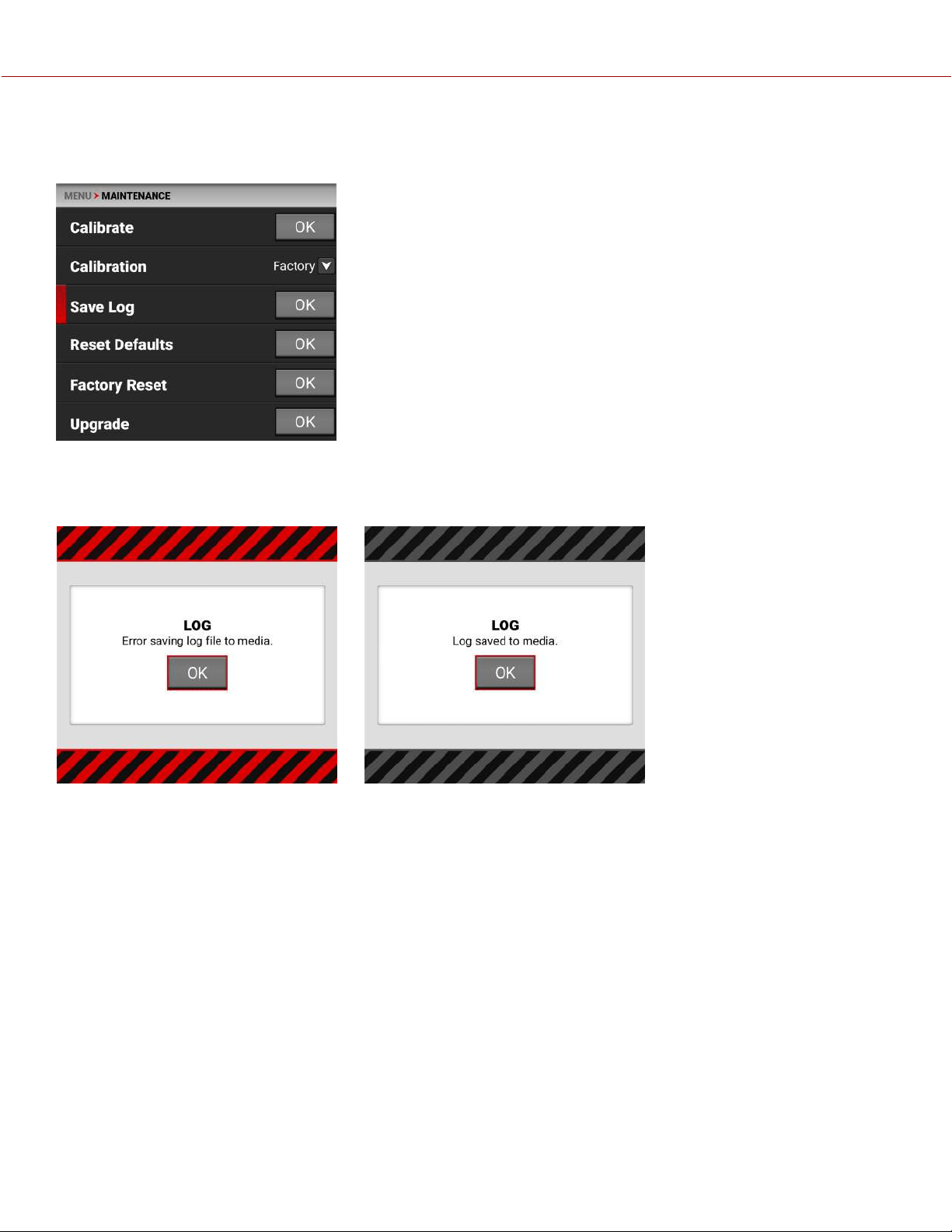
SAVE LOG
Use Save Log to save the camera log to the media.
When the media is full, or missing, the camera will display an error message. When there is no error, the success
message is displayed.
Error: Success:
COPYRIGHT © 2023 RED.COM, LLC 955-0218, REV A | 184
KOMODO-X
®
OPERATION GUIDE
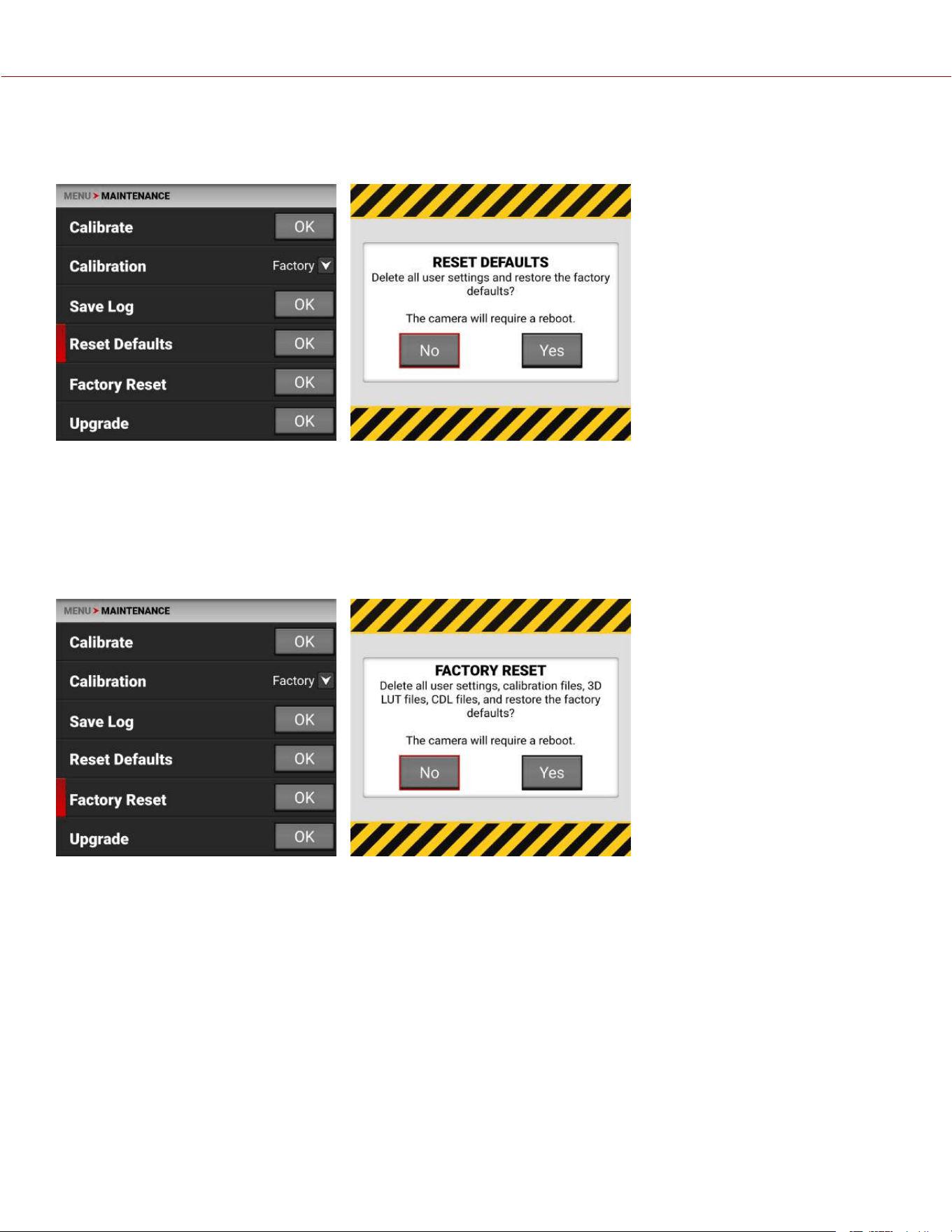
RESET DEFAULTS
Use Reset Defaults to reset the camera to the factory default settings.
NOTE: Resetting the camera will delete all of your menu settings.
NOTE: The camera turns off, and then back on to complete the reset process.
Tap Yes on the touchscreen to reset the camera menus to the default settings.
FACTORY RESET
Use Factory Reset to reset the camera to the factory settings.
NOTE: Resetting the camera will delete all of your settings and remove all imported files. The camera turns off, and then
back on to complete the reset process.
Tap Yes on the touchscreen to reset the camera to the factory settings.
COPYRIGHT © 2023 RED.COM, LLC 955-0218, REV A | 185
KOMODO-X
®
OPERATION GUIDE
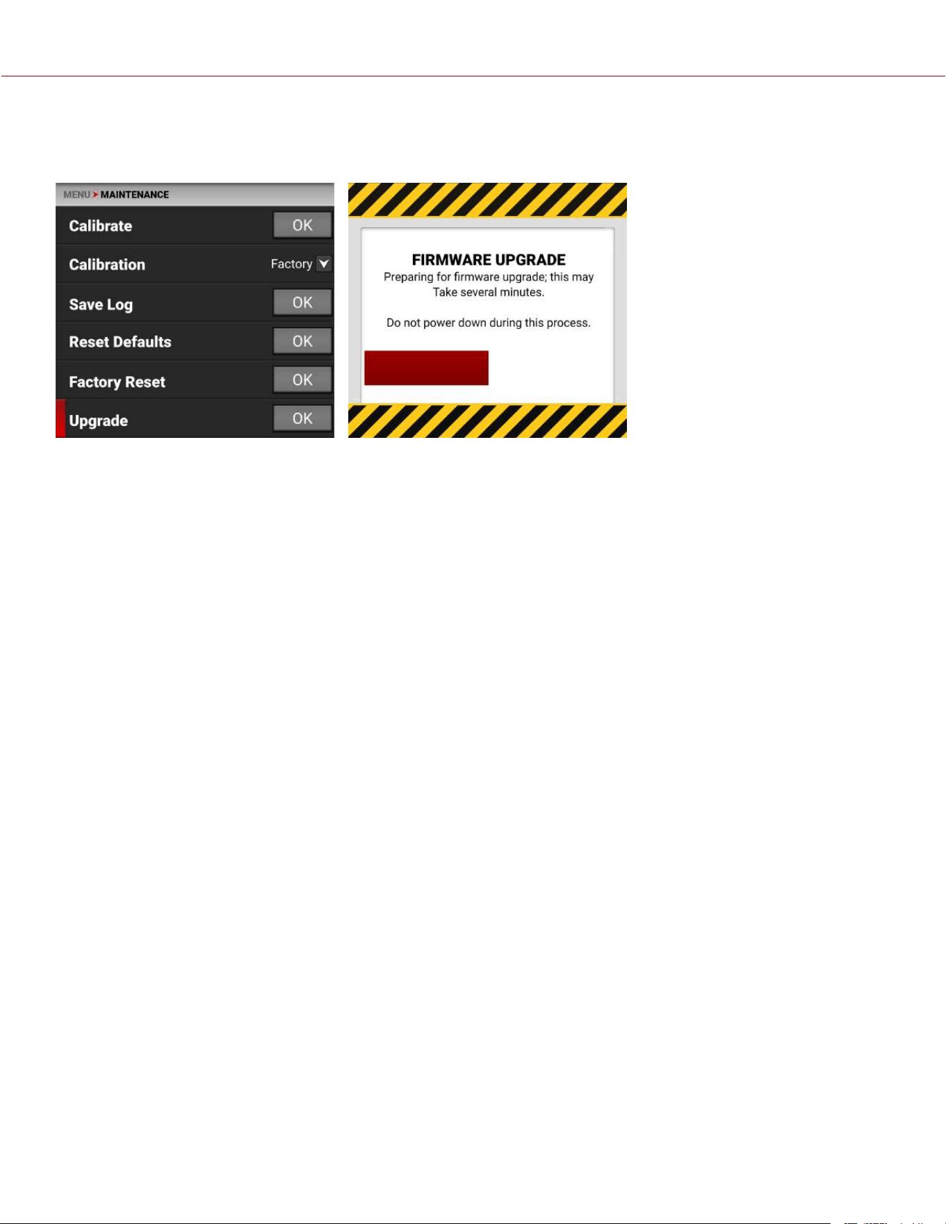
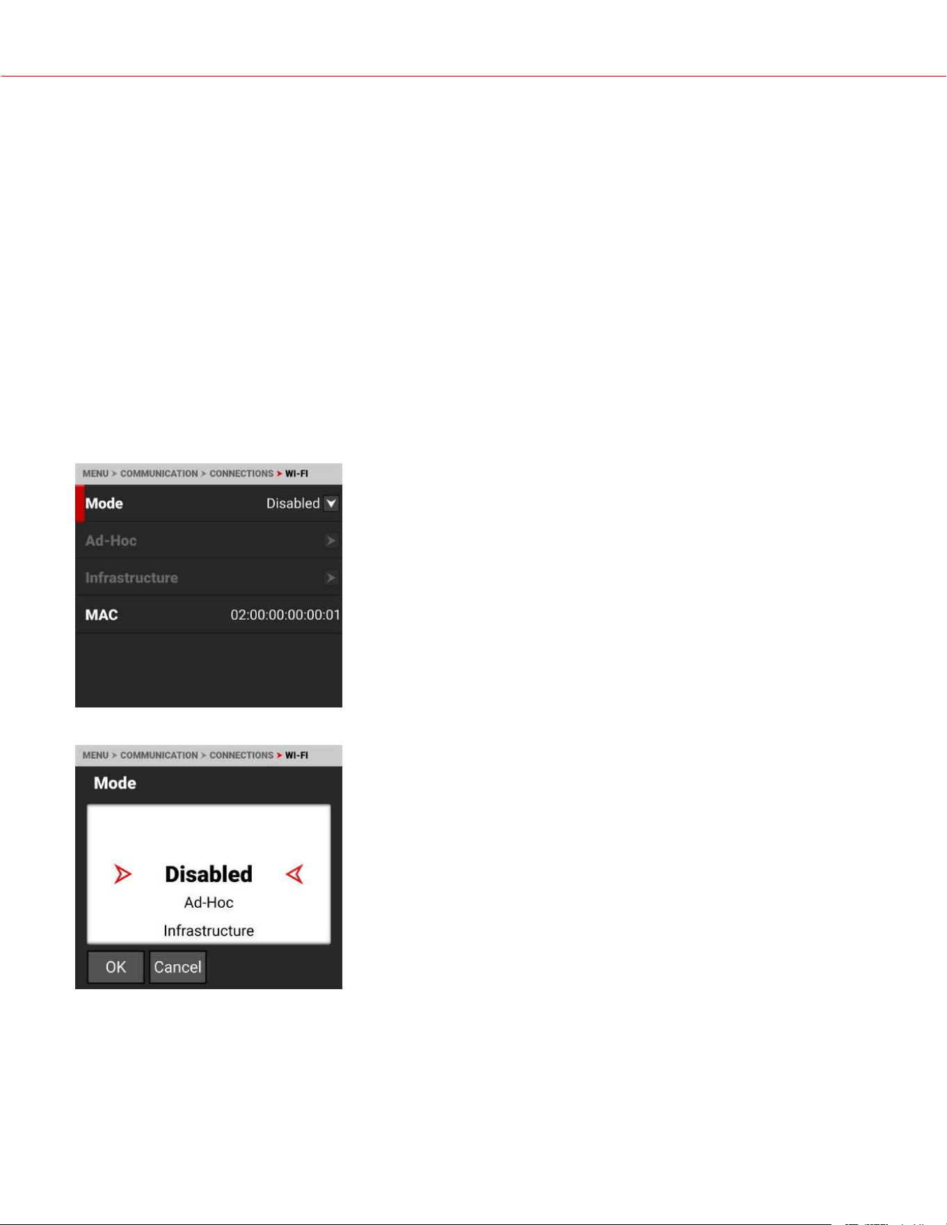
COPYRIGHT © 2023 RED.COM, LLC 955-0218, REV A | 187
5. HOW TO
This section describes how you can use the camera features.
WI-FI CONFIGURATION
The camera offers a wireless (802.11g) connection that provides communication support for third-party applications. As
with all wireless devices, the communication range varies with the environment and any radio frequency (RF)
interference that may be present. You can select a wireless frequency of 2.4 GHz or 5 GHz. For optimal performance,
do not obstruct the antenna with any accessory, mounting plate, or mounting rail.
The camera uses Ad-Hoc mode to set up the camera as a Wi-Fi hot spot.
The camera uses Infrastructure mode to connect to existing Wi-Fi infrastructure.
CONNECTING WIRELESSLY TO AN EXISTING WI-FI NETWORK
This camera uses the WPA2 Wi-Fi protocol.
1. Navigate to the Wi-Fi menu MENU > COMMUNICATION > Wi-Fi.
2. From the Mode option, select Infrastructure.
KOMODO-X
®
OPERATION GUIDE

3. From the Infrastructure menu, select Networks:
4. Select the network name from the Networks list menu:
or tap SCAN to scan for available networks and update the Networks list:
COPYRIGHT © 2023 RED.COM, LLC 955-0218, REV A | 188
KOMODO-X
®
OPERATION GUIDE
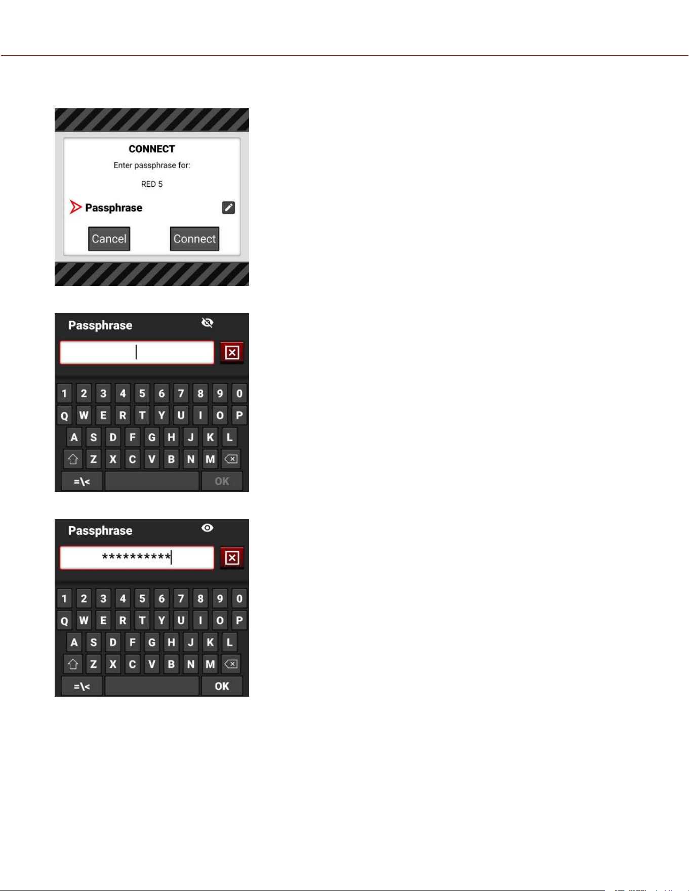
5. Tap CONNECT. The CONNECT screen displays:
6. Tap Passphrase. The Passphrase entry screen displays:
7. Enter the passphrase for the selected network. The passphrase must use a minimum of 8 characters.
COPYRIGHT © 2023 RED.COM, LLC 955-0218, REV A | 189
KOMODO-X
®
OPERATION GUIDE
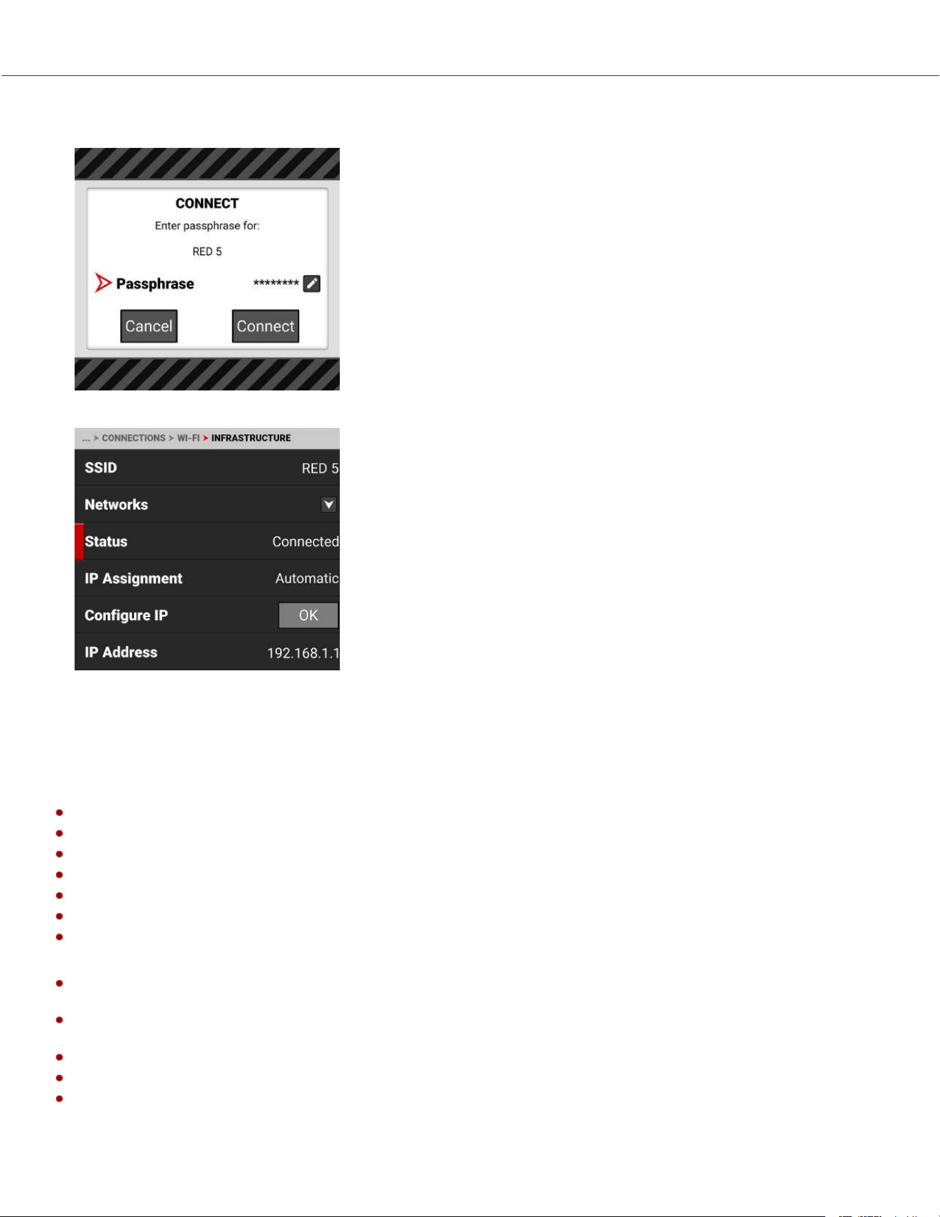
8. Tap OK on the completed Passphrase entry screen. The completed CONNECT screen displays.
9. Tap the Connect button. The camera connects to the selected network:
FTPS CONFIGURATION
The File Transfer Protocol Secure (FTPS) offers a fast and secure system for transferring data to and from the camera.
FTPS is supported by firmware versions 1.5 and higher. FTPS is available when the camera is enabled and connected
to a network over WiFi or through the USB-C port to an Ethernet adaptor.
The settings for using FTPS on the camera include:
Protocol: FTP or FTPS
Host: [IP address of the camera]
Port: 21
Encryption: TLS/SSL Explicit encryption
Username: [Username in FTPS menu settings]
Password: [Password in FTPS menu settings]
Logon Type: Normal
NOTE:
File transfer speeds may vary depending on the strength of the signal (when using WiFi) and the amount of network
traffic. For the fastest and most reliable data transfer, we recommend using a hard-wired connection.
Steps may differ depending on which FTP software you wish to use, consult your software’s user guide for additional
assistance.
When setting up FTP, make sure you use FTP or FTPS and not SFTP as these are different protocols.
For security reasons, the FTPS host name and password are only displayed on the camera FTPS menu.
Disabling encryption can increase transmission speeds.
COPYRIGHT © 2023 RED.COM, LLC 955-0218, REV A | 190
KOMODO-X
®
OPERATION GUIDE
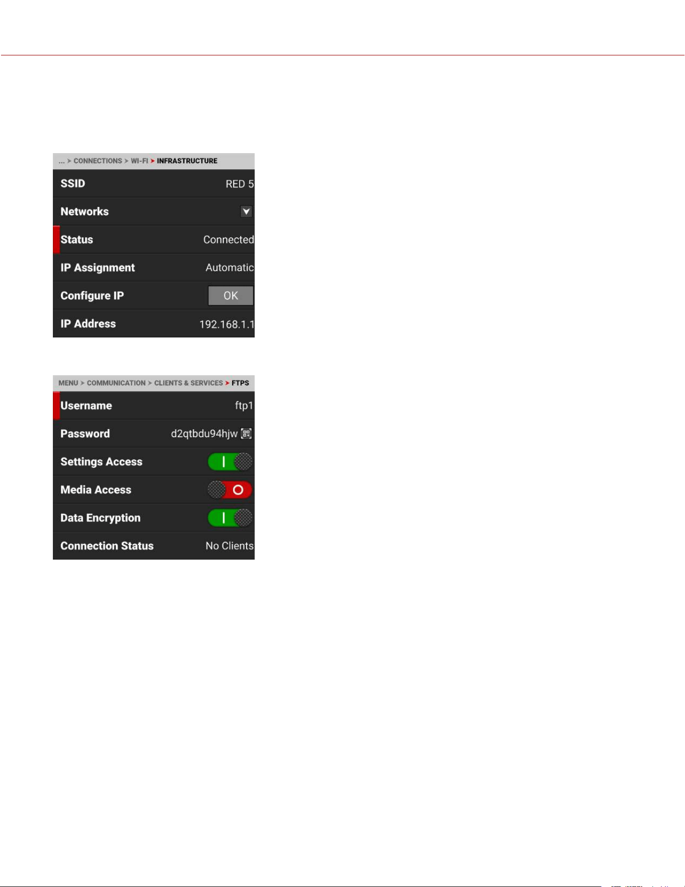
CAMERA SET-UP
1. Connect your camera to the network with the desired connection method (Ad-Hoc, Infrastructure or USB-C) and
verify the connection. A successful connection is confirmed when the camera displays an IP address in the WiFi or
USB-C settings menus.
2. Navigate to Menu > Communication > Clients & Services > FTPS. Take note of the username and password. You can
also enter a new password QR code.
3. Enable the permissions you want users to have access to by toggling Settings Access or Media Access to the on or
off position. The media folder will display as an empty folder on the FTP App when Media Access is disabled (off).
4. The camera is now set-up on FTPS.
COPYRIGHT © 2023 RED.COM, LLC 955-0218, REV A | 191
KOMODO-X
®
OPERATION GUIDE
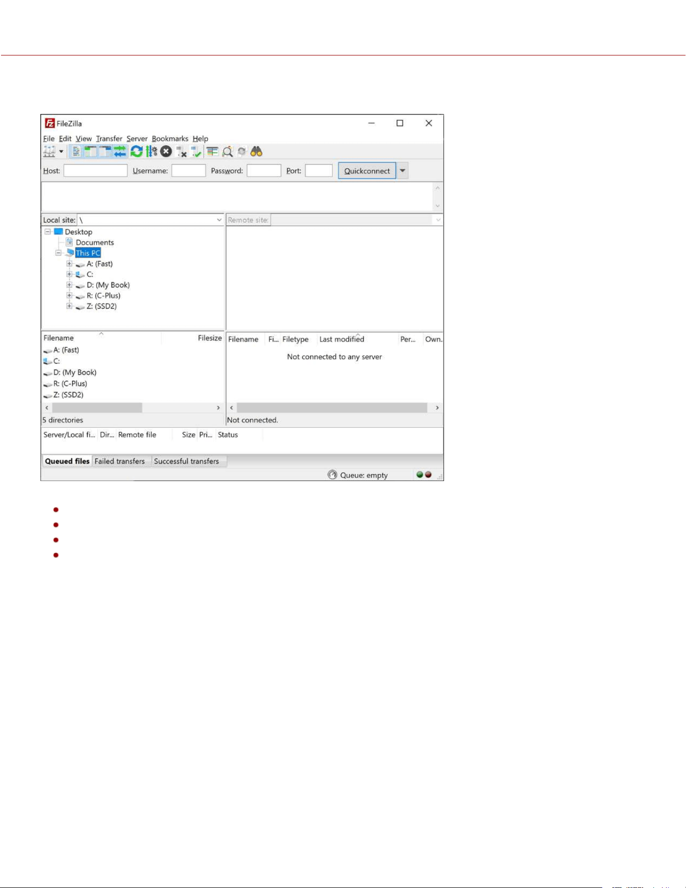
SOFTWARE SET-UP (FILEZILLA)
1. In FileZilla, enter the following settings:
Host: ftp://Camera's IP Address - Example: ftp://192.168.1.93
Username: Username displayed in the camera's FTPS menu
Password: Password displayed in the camera's FTPS menu
Port: leave blank
COPYRIGHT © 2023 RED.COM, LLC 955-0218, REV A | 192
KOMODO-X
®
OPERATION GUIDE
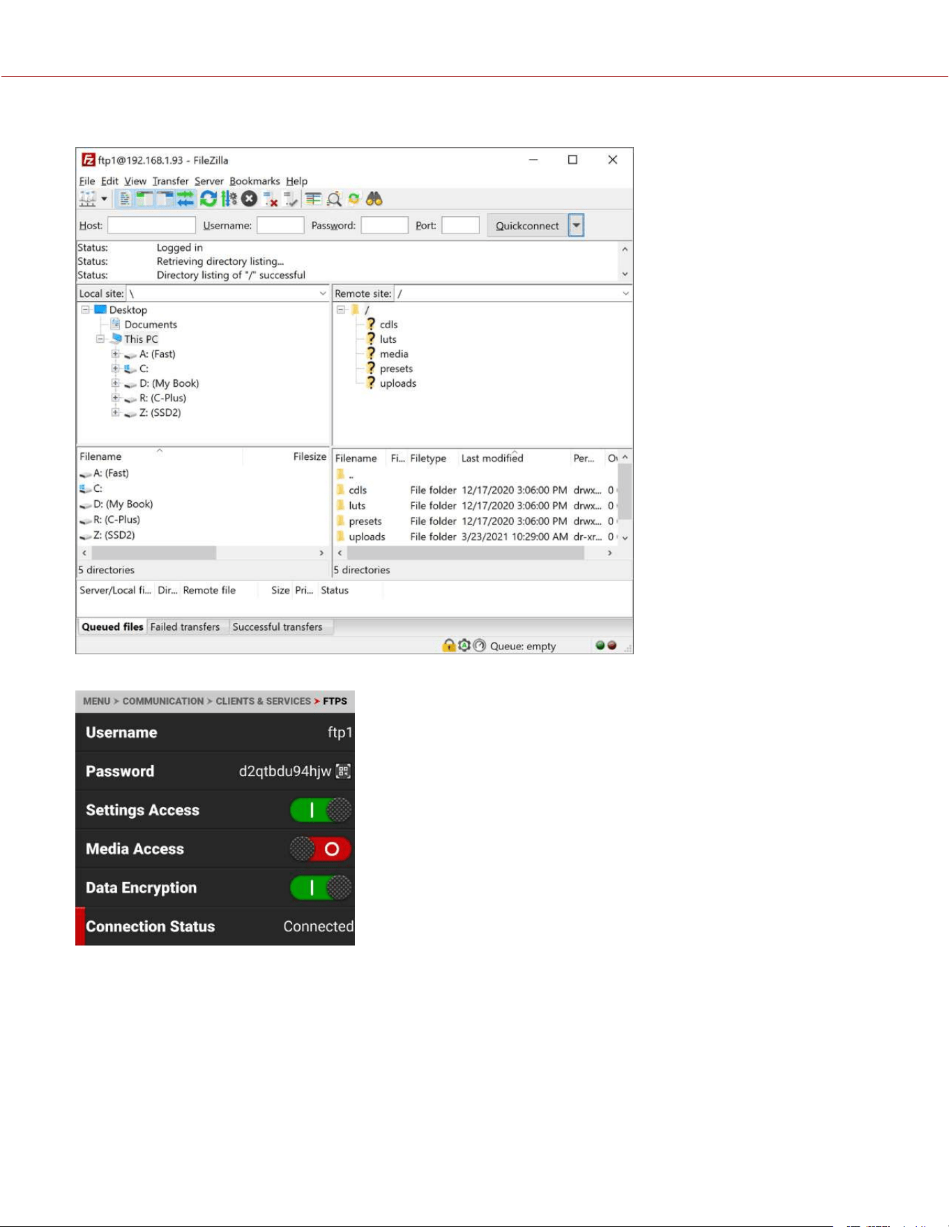
2. Press Quickconnect. Depending on the permissions you will now have access to the desired folders.
The camera FTPS menu Connection Status displays Connected:
ADDITIONAL INFORMATION
When uploading files to the camera make sure that you use the ‘upload’ folder & then the desired sub-directory of luts,
cdls, presets or upgrade. Media cannot be uploaded to the camera.
The data rate of the FTPS transfer with encryption maxes out at roughly Gigabit Ethernet speeds.
Estimated download time for a full 256 GB is approximately 47 minutes when using a wired connection.
COPYRIGHT © 2023 RED.COM, LLC 955-0218, REV A | 193
KOMODO-X
®
OPERATION GUIDE
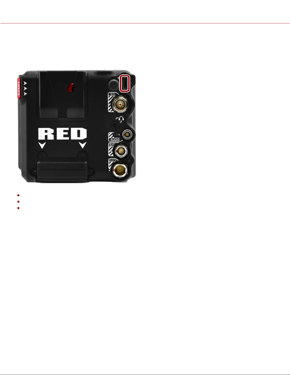
USB-C CONFIGURATION
KOMODO-X offers a USB-C 3.0 protocol connection that provides communication support for Android devices, Apple
devices, Ethernet devices, and R3D streaming with the RED Connect License (with 5 Gb/s Ethernet adapter).
For more information about RED Connect refer to: RED Connect.
This section includes instructions for:
USB-C Android Configuration
USB-C Apple Configuration
USB-C Ethernet Configuration
COPYRIGHT © 2023 RED.COM, LLC 955-0218, REV A | 194
KOMODO-X
®
OPERATION GUIDE
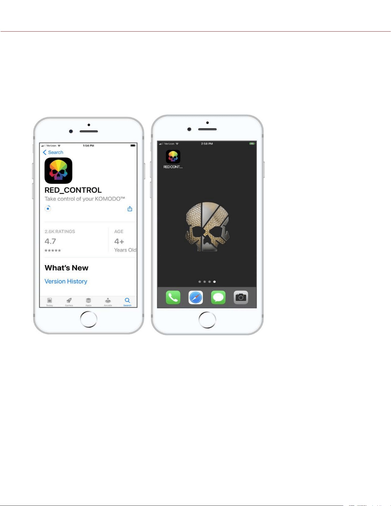
USB-C APPLE CONFIGURATION
The KOMODO-X offers a USB-C 3.0 protocol connection that provides communication support for Apple devices.
CONNECTING TO AN APPLE DEVICE
1. From the Apple store, download the RED Control Apps to the Apple device.
Note: Scroll to the bottom of the user agreement to accept the agreement.
2. Connect the Apple device to the camera with a USB-C cable. If the "Trust This Computer?" message displays, skip to
step 6.
COPYRIGHT © 2023 RED.COM, LLC 955-0218, REV A | 195
KOMODO-X
®
OPERATION GUIDE
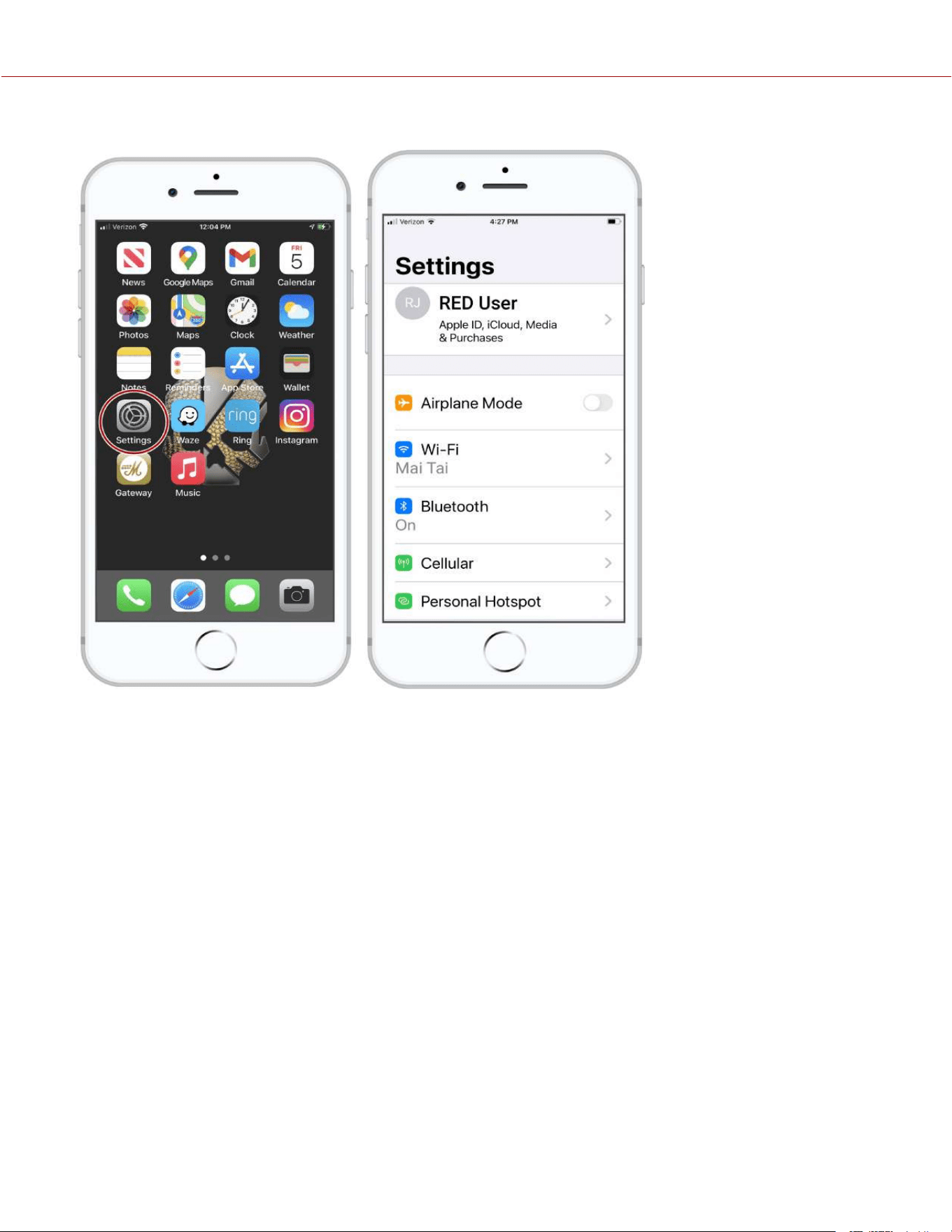
3. Open the Apple device settings by tapping the Settings icon.
COPYRIGHT © 2023 RED.COM, LLC 955-0218, REV A | 196
KOMODO-X
®
OPERATION GUIDE
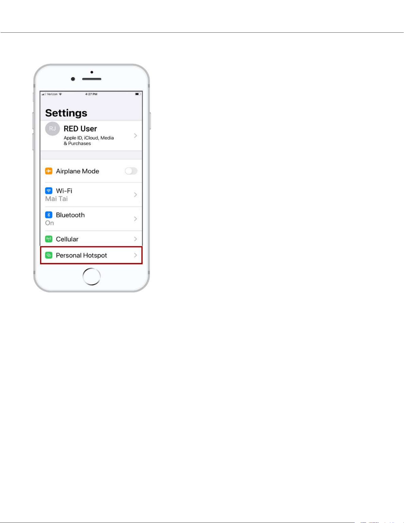
4. Select Personal Hotspot.
COPYRIGHT © 2023 RED.COM, LLC 955-0218, REV A | 197
KOMODO-X
®
OPERATION GUIDE
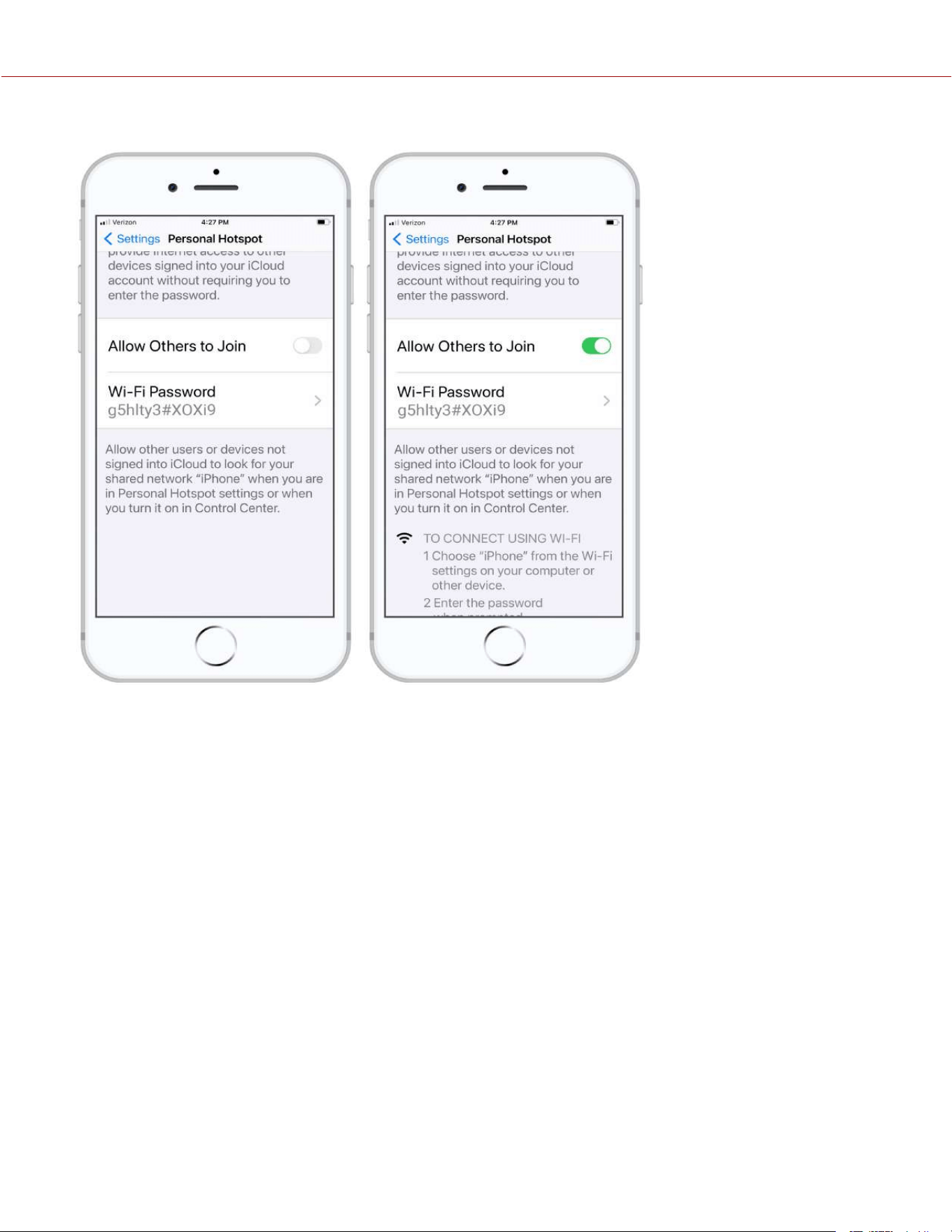
5. Allow others to join.
COPYRIGHT © 2023 RED.COM, LLC 955-0218, REV A | 198
KOMODO-X
®
OPERATION GUIDE
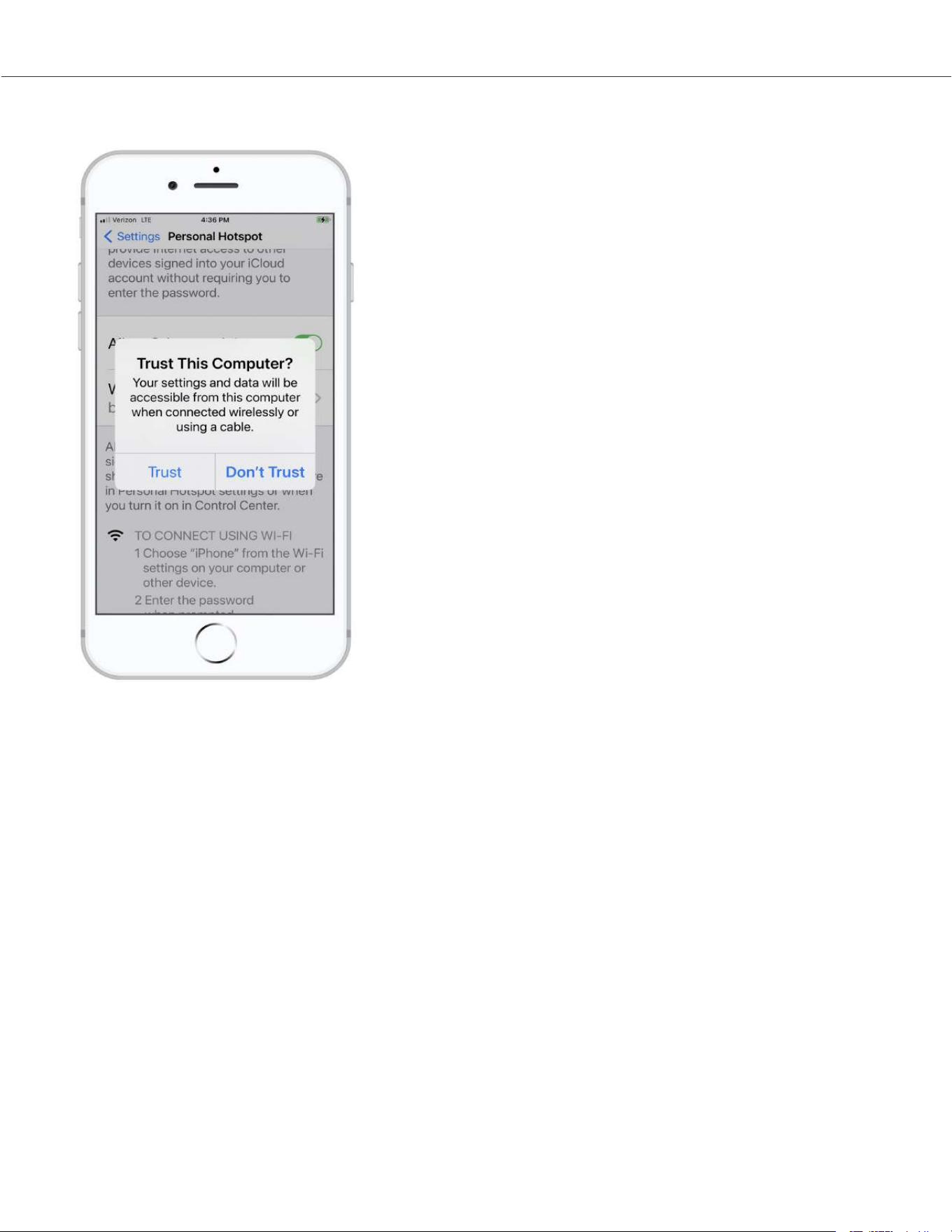
6. The Apple device prompts you to acknowledge that you trust the computer (camera).
COPYRIGHT © 2023 RED.COM, LLC 955-0218, REV A | 199
KOMODO-X
®
OPERATION GUIDE
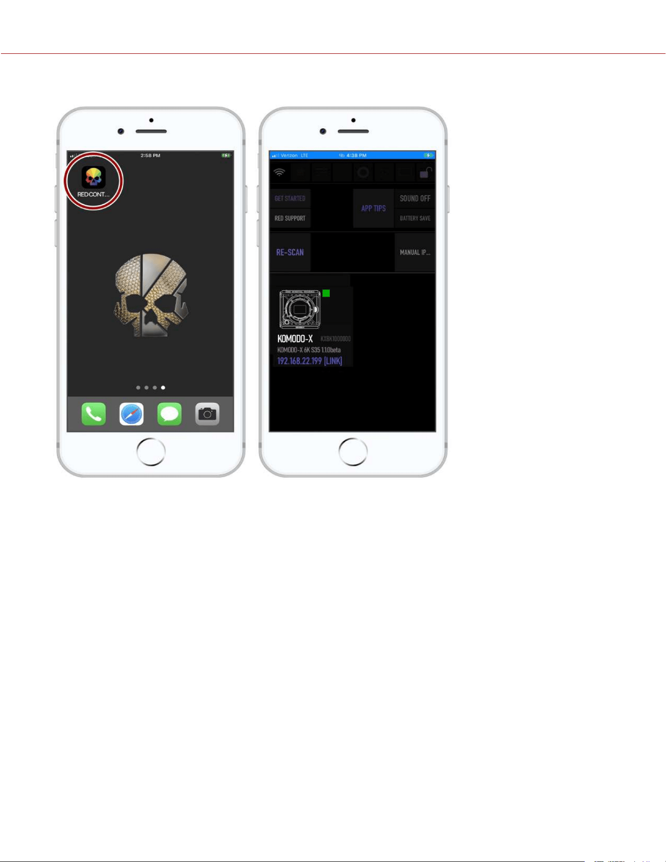
7. From the Apple device, tap the RED Control icon to open the RED Control app.
COPYRIGHT © 2023 RED.COM, LLC 955-0218, REV A | 200
KOMODO-X
®
OPERATION GUIDE

The RED Control app displays the camera connection icon. The word LINK is visible after the IP address.
8. Tap the icon to open the RED Control app tools for the connected camera.
From here you can use the RED Control Apps to monitor and control the camera.
COPYRIGHT © 2023 RED.COM, LLC 955-0218, REV A | 201
KOMODO-X
®
OPERATION GUIDE

USB-C ANDROID CONFIGURATION
The KOMODO-X offers a USB-C 3.0 protocol connection that provides communication support for Android devices.
CONNECTING TO AN ANDROID DEVICE
1. From the Google Play store, download the RED Control App to the Android device.
2. Connect the Android device to the camera with a USB-C cable.
COPYRIGHT © 2023 RED.COM, LLC 955-0218, REV A | 202
KOMODO-X
®
OPERATION GUIDE

3. Open the Android device settings by tapping the Settings icon (gear).
COPYRIGHT © 2023 RED.COM, LLC 955-0218, REV A | 203
KOMODO-X
®
OPERATION GUIDE
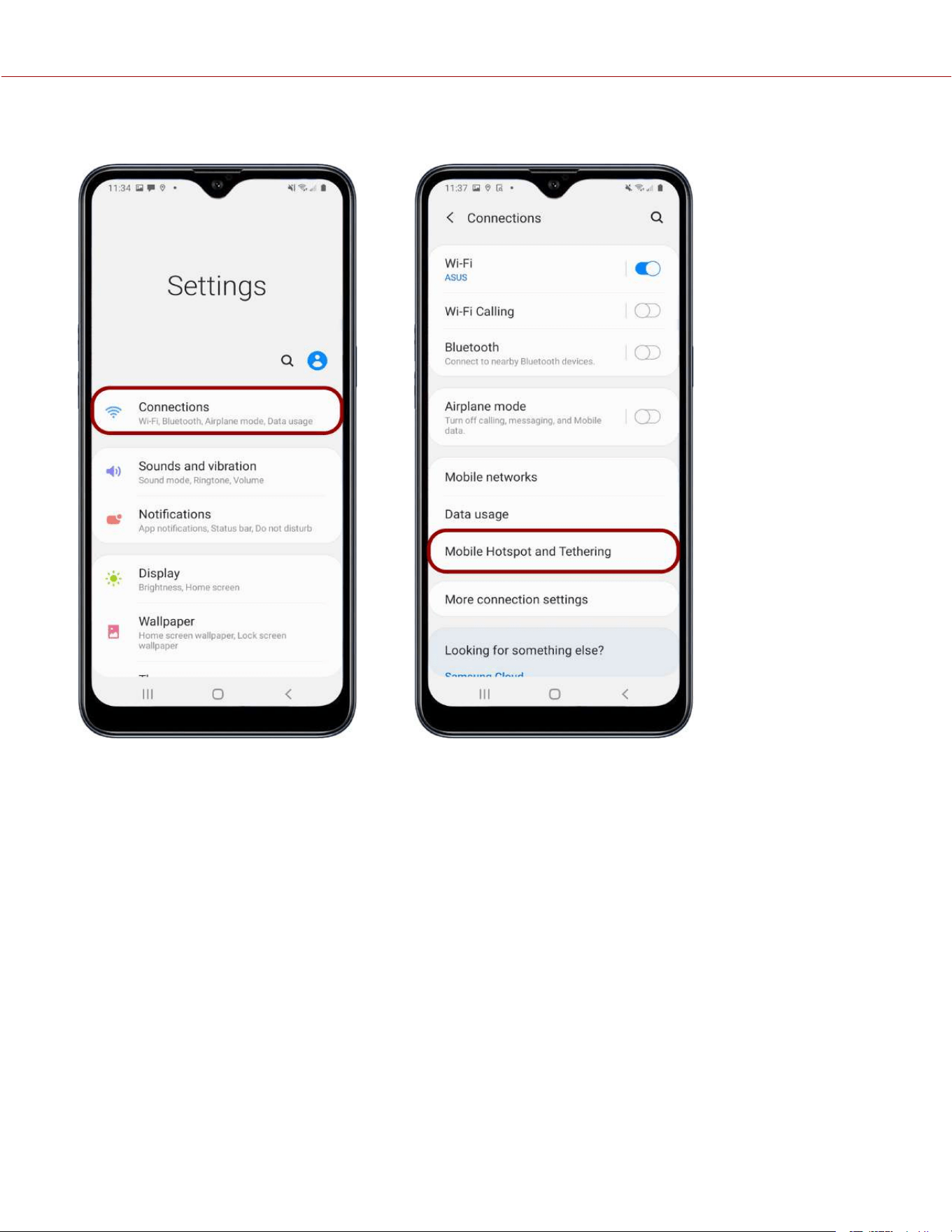
4. Select Connections. 5. Select Mobile Hotspot and Tethering.
NOTE: Mobile Hotspot and Tethering is only available on Android devices with cellular capability.
COPYRIGHT © 2023 RED.COM, LLC 955-0218, REV A | 204
KOMODO-X
®
OPERATION GUIDE
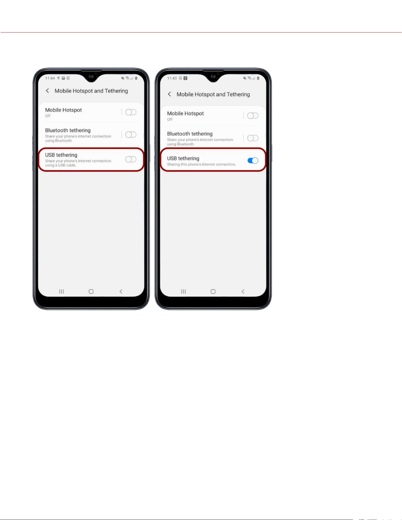
6. Enable USB Tethering.
COPYRIGHT © 2023 RED.COM, LLC 955-0218, REV A | 205
KOMODO-X
®
OPERATION GUIDE
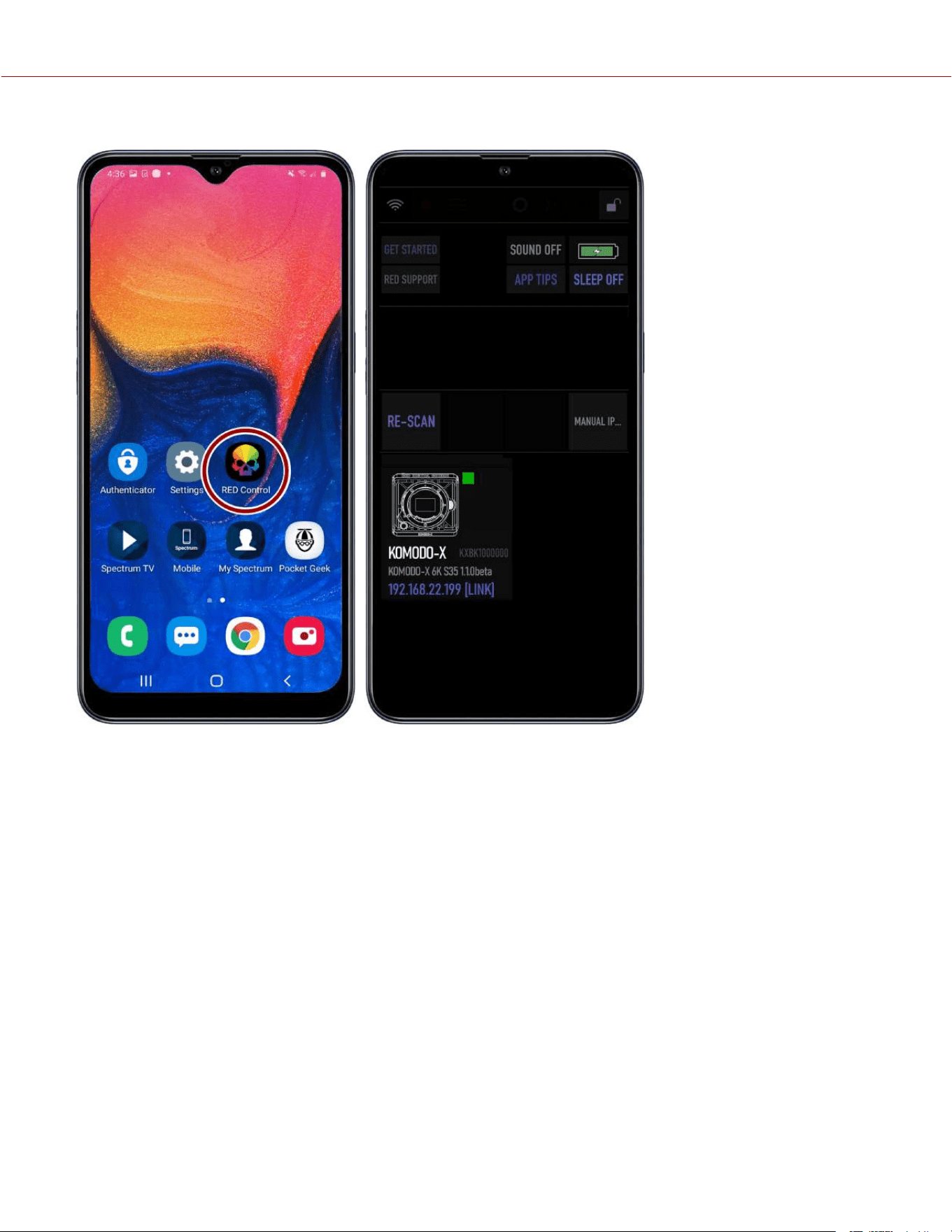
7. From the Android device, tap the RED Control icon to open the RED Control app.
COPYRIGHT © 2023 RED.COM, LLC 955-0218, REV A | 206
KOMODO-X
®
OPERATION GUIDE
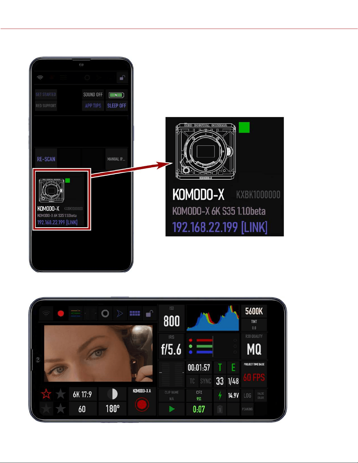
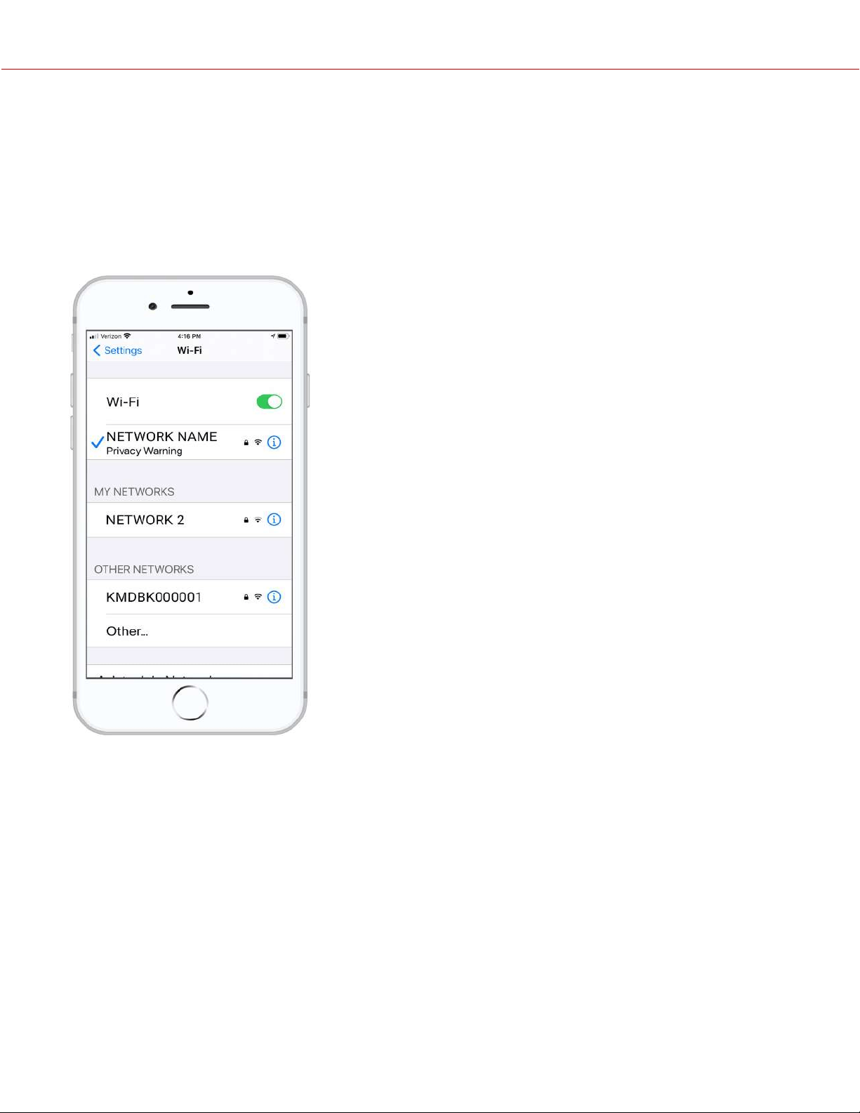
USB-C ETHERNET CONFIGURATION
The KOMODO-X offers a USB-C 3.0 protocol connection that provides communication support for Ethernet networks.
CONNECTING TO AN ETHERNET NETWORK
You must use a USB-C to Ethernet adapter to connect the camera to an Ethernet network.
1. Connect the camera to the Ethernet network using the USB-C to Ethernet adapter.
2. From a Wi-Fi-enabled device, select the Wi-Fi connection to which the camera is connected.
COPYRIGHT © 2023 RED.COM, LLC 955-0218, REV A | 208
KOMODO-X
®
OPERATION GUIDE
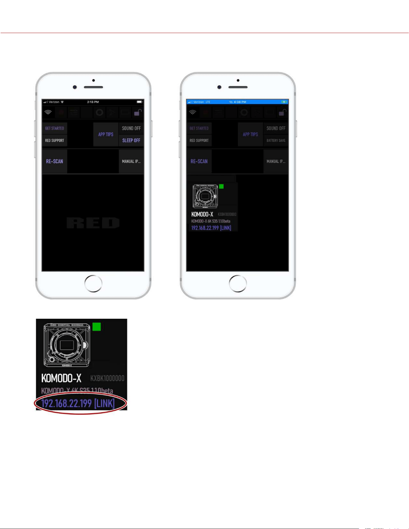
3. Open RED Control on the
Wi-Fi-enabled device.
4. Tap RE-SCAN.
The camera icon displays.
The camera icon displays the camera's Ethernet IP address:
COPYRIGHT © 2023 RED.COM, LLC 955-0218, REV A | 209
KOMODO-X
®
OPERATION GUIDE
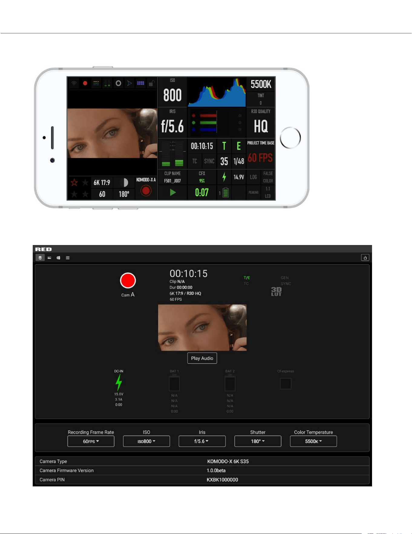
5. Tap the camera icon to open the RED Control app tools for the networked camera.
6. Open a browser from a computer connected to the Ethernet network.
7. In the browser address field, enter the camera IP address displayed on the RED Control camera icon or the camera
Communication menus (Ad-Hoc, Infrastructure). The RED Control tools are displayed in the browser.
COPYRIGHT © 2023 RED.COM, LLC 955-0218, REV A | 210
KOMODO-X
®
OPERATION GUIDE
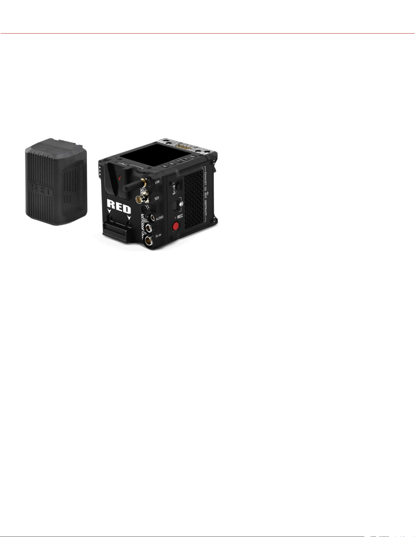
POWER
The camera accepts power through a DC-IN port and through an attached battery. The camera cannot accept power
through USB, or BNC ports. For more information, refer to 6-pin DC-IN, KOMODO-X™ Power AdaptorREDVOLT®
NANO-V Battery, and REDVOLT® MICRO-V Battery.
ATTACHING THE BATTERY
Attach a compatible V-Lock battery (refer to REDVOLT® NANO-V Battery and REDVOLT® MICRO-V Battery) in the V-
Lock battery mount. Slide the battery down until the locking mechanism clicks.
V-Lock batteries with a width greater than 2.95 in. (75
mm) are not compatible with the camera’s Micro V-
Lock plate and will require a battery adapter.
The camera can charge the installed battery when the
camera is off and the DC power Adaptor is
connected. The camera charges the batteries only
when the camera is off and the power Adaptor is
connected. While the battery is charging the DC
Power LED blinks amber until communication is
established. The LED is solid amber when
communication is established and the battery is
charging. The LED is green when communication is
not established (incompatible battery) and the battery
is not charging.
NOTE: An incompatible battery will not charge on the camera.
REMOVING THE BATTERY
Remove the battery when the charge is low or when you are storing the camera.
1. Turn off the camera.
2. While holding the attached battery, press the battery Eject Button.
3. Slide and lift the battery up.
POWER COMPONENTS
You can power the camera with the KOMODO-X™ Power Adaptor, an External DC Power Source, or with a rear-
mounted REDVOLT® MICRO-V Battery or REDVOLT® NANO-V Battery.
For information about charging, storing, or maintaining the batteries, refer to the manufacturer's instructions.
AUTO BOOT ON POWER
The camera supports the Auto Boot on Power feature. This means that if all power sources are removed, and the Power
Switch is set to ON, then when a power source is attached, the camera turns on.
COPYRIGHT © 2023 RED.COM, LLC 955-0218, REV A | 211
KOMODO-X
®
OPERATION GUIDE
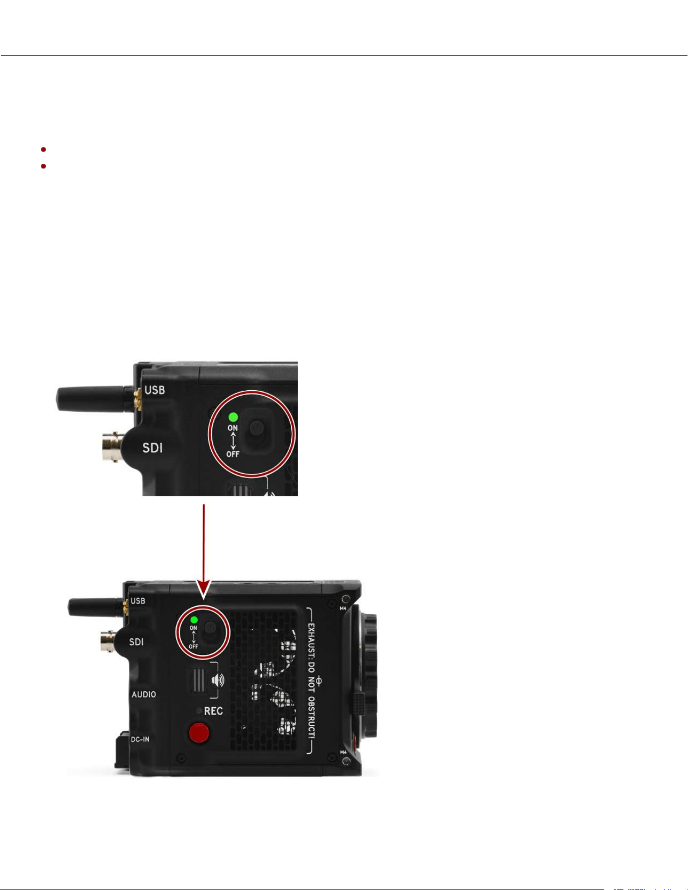
POWER CONSUMPTION
The camera draws various levels of power depending on the configuration and operating conditions. When there are no
auxiliary (AUX) power draws on the camera, the power consumption guidelines are:
28 Watts of power in the camera's basic recording configuration at room temperature, 6K, and 24 frames per second
45 Watts of power when using DSMC3 RED Touch 7", at room temperature, 6K, and 80 frames per second
POWER PRIORITY
When multiple power sources are connected to the camera, power consumption is prioritized in this sequence:
1. Any power supply connected to the DC IN port.
2. Attached V-Lock battery.
WARNING: Always attach the power or battery before attaching the SDI BNC cable. Always remove the SDI BNC cable
before removing the power or battery.
TURNING ON THE CAMERA
1. Attach a power source (REDVOLT® MICRO-V Battery or DC-Input) to the camera.
2. Slide the Power Switch up to the ON position.
COPYRIGHT © 2023 RED.COM, LLC 955-0218, REV A | 212
KOMODO-X
®
OPERATION GUIDE
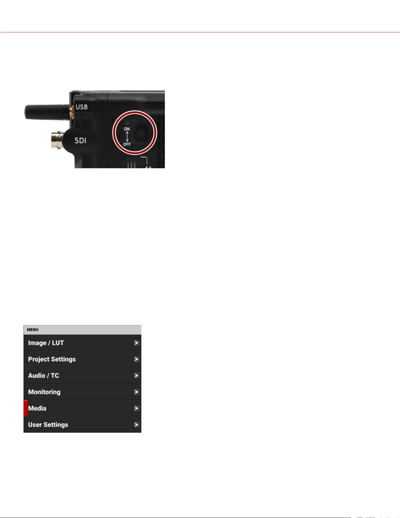
TURNING OFF THE CAMERA
NOTE: Do not turn off the camera while the camera is recording, or formatting media.
Slide the Power Switch down to the OFF position.
MEDIA MANAGEMENT
This section explains how to use, record, format, and offload media for the camera.
WARNING: Do not attach a label to the media card. The heat generated by the media can weaken the label's adhesive,
causing the label to detach inside of the camera. Labels can also diminish heat dissipation and cause excessive wear to
the internal components. Removing a label from a media card can possibly deform the card body.
The camera supports exFAT as the file system for the media card to accommodate larger files and data rates. exFAT is
supported both on macOS and MS Windows.
Format your media in the camera whenever possible (refer to Media Best Practices).
EJECTING (UNMOUNTING) MEDIA
IMPORTANT: To ensure data integrity, media must always be ejected (unmounted) prior to removal from the camera.
This ensures that power is removed from the media and any open data files are closed. Failure to properly eject
(unmount) media may result in lost data or corrupted files.
To eject (unmount) media from the camera, use the Onboard LCD Touchscreen and select Menu > Media.
COPYRIGHT © 2023 RED.COM, LLC 955-0218, REV A | 213
KOMODO-X
®
OPERATION GUIDE
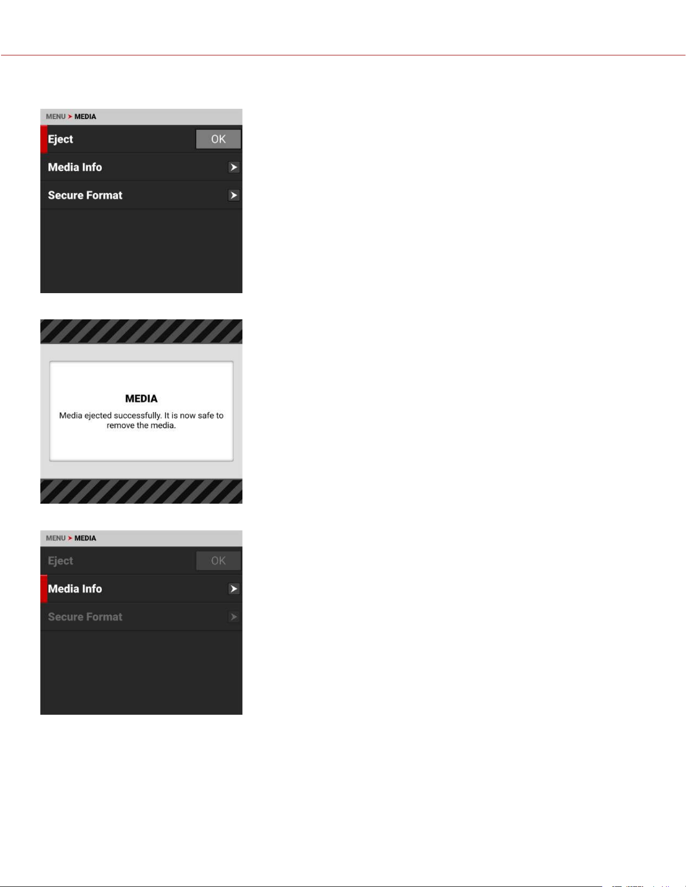
Tap the Eject OK button:
The Success message displays:
The media is now ejected (unmounted) and all media related items are grayed out in the menu.
WARNING: The media can get extremely hot. Use caution when removing
media.
Removing a media card without ejecting (unmounting) first does not damage
the media, however, it does increase the risk of file corruption. It is good
practice to eject the media before removing or disconnecting. Ejecting the
media provides the following benefits:
- Protects the integrity of your recorded data
- Mounts clips instantly to your workstation in post-production.
COPYRIGHT © 2023 RED.COM, LLC 955-0218, REV A | 214
KOMODO-X
®
OPERATION GUIDE
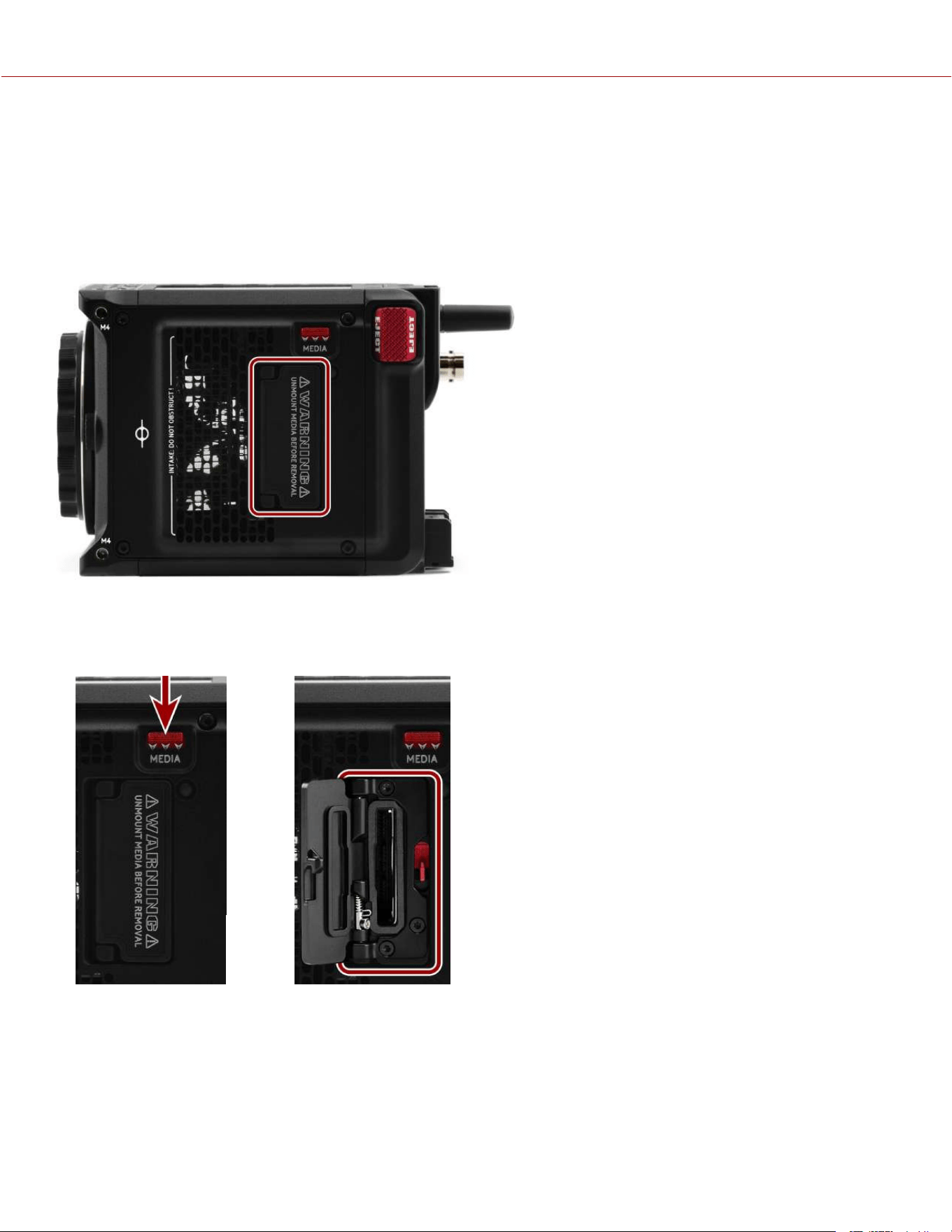
INSERTING THE MEDIA
The camera contains a covered compartment on the right side where you insert the CFexpress media card.
WARNING: Do not attach a label to the CFexpress media card. The heat generated by the media can weaken the
label's adhesive, causing the label to detach inside of the camera. Labels can also diminish heat dissipation and cause
excessive wear to the internal components. Removing a label from a CFexpress media card can possibly deform the
card body.
INSERTING THE MEDIA CARD
1. Press the media door latch down, and the media door opens.
2. Insert the CFexpress media card in the slot with the top of the card facing toward the front of the camera. Insert the
card until it is firmly seated.
3. Close the media door and make sure that the door latch clicks.
4. If needed, format the CFexpress media card. Refer to Secure Format for more information.
COPYRIGHT © 2023 RED.COM, LLC 955-0218, REV A | 215
KOMODO-X
®
OPERATION GUIDE
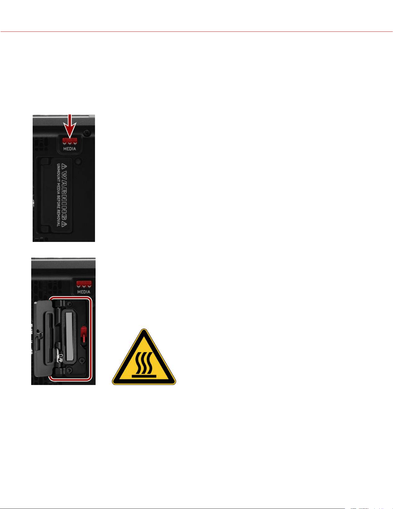
REMOVING THE MEDIA CARD
NOTE: Do not remove the CFexpress card while the camera is recording or formatting media. Refer to Media
Management for more information.
WARNING: The media can get extremely hot. Use caution when removing media.
1. If the camera is on, go to Menu >Media and select Eject.
2. Press the media door latch down, and the media door opens.
3. Press the CFexpress media card until you hear a click, and then release the card and it will slide out.
4. Let the CFexpress media card cool before gently pulling the card out of the slot.
WARNING: The media can get extremely hot. Use caution when removing media.
5. Close the media door and make sure that the door latch clicks.
COPYRIGHT © 2023 RED.COM, LLC 955-0218, REV A | 216
KOMODO-X
®
OPERATION GUIDE
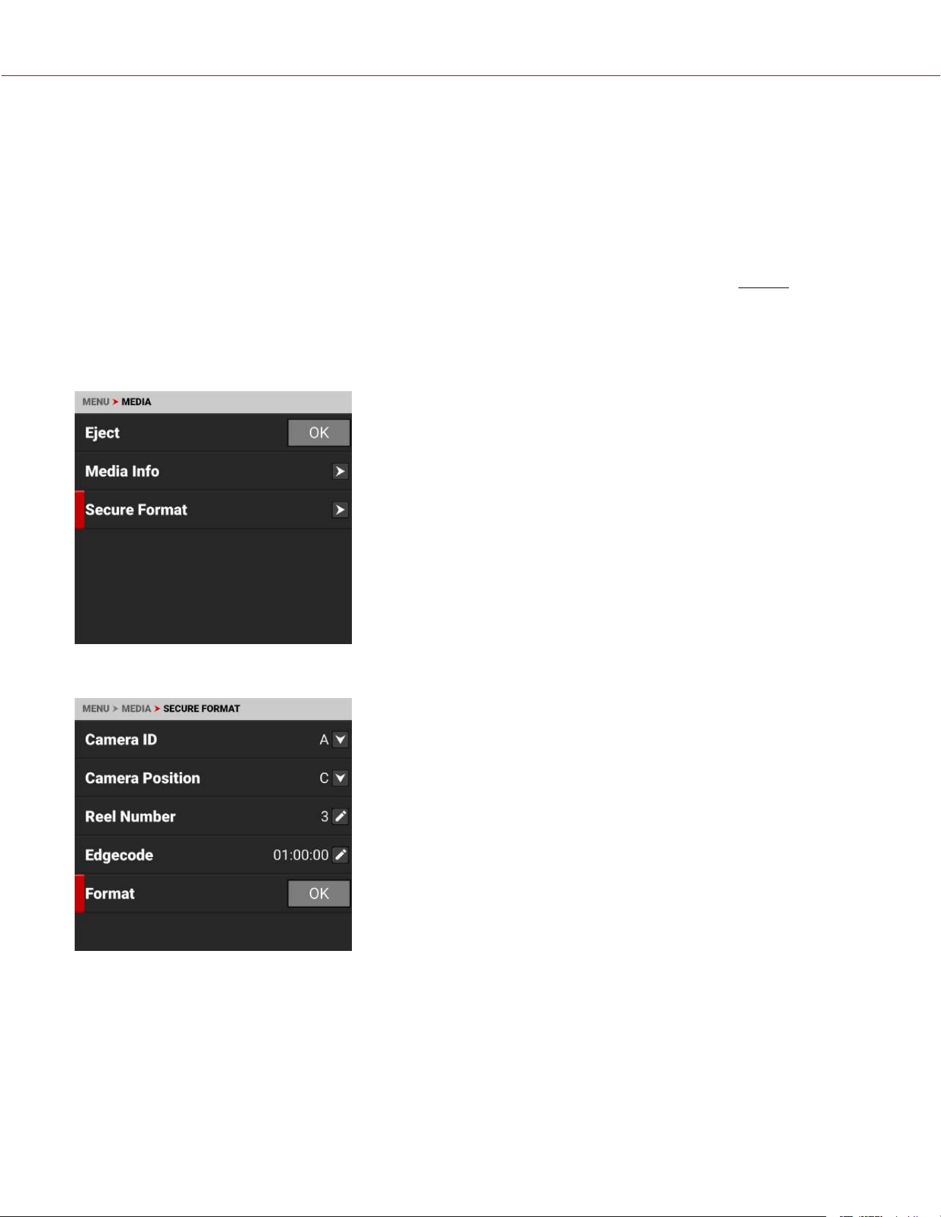
SECURE FORMAT
A secure format is a low-level format that rebuilds the media card file system. A secure format erases all data on the
card.
Perform a secure format when the camera is reporting media-related errors.
PERFORMING A SECURE FORMAT
CAUTION: Ensure all data is backed up before formatting a card. Data erased during formatting cannot be
recovered.
WARNING: The media can get extremely hot. Use caution when removing media.
To perform a secure format, follow the instructions below:
1. Go to MENU > MEDIA > SECURE FORMAT:
2. From the Secure Format menu, select the desired Camera ID, Camera Position, Reel Number and Edgecode. Tap the
Format button to start the Secure Format process:
COPYRIGHT © 2023 RED.COM, LLC 955-0218, REV A | 217
KOMODO-X
®
OPERATION GUIDE
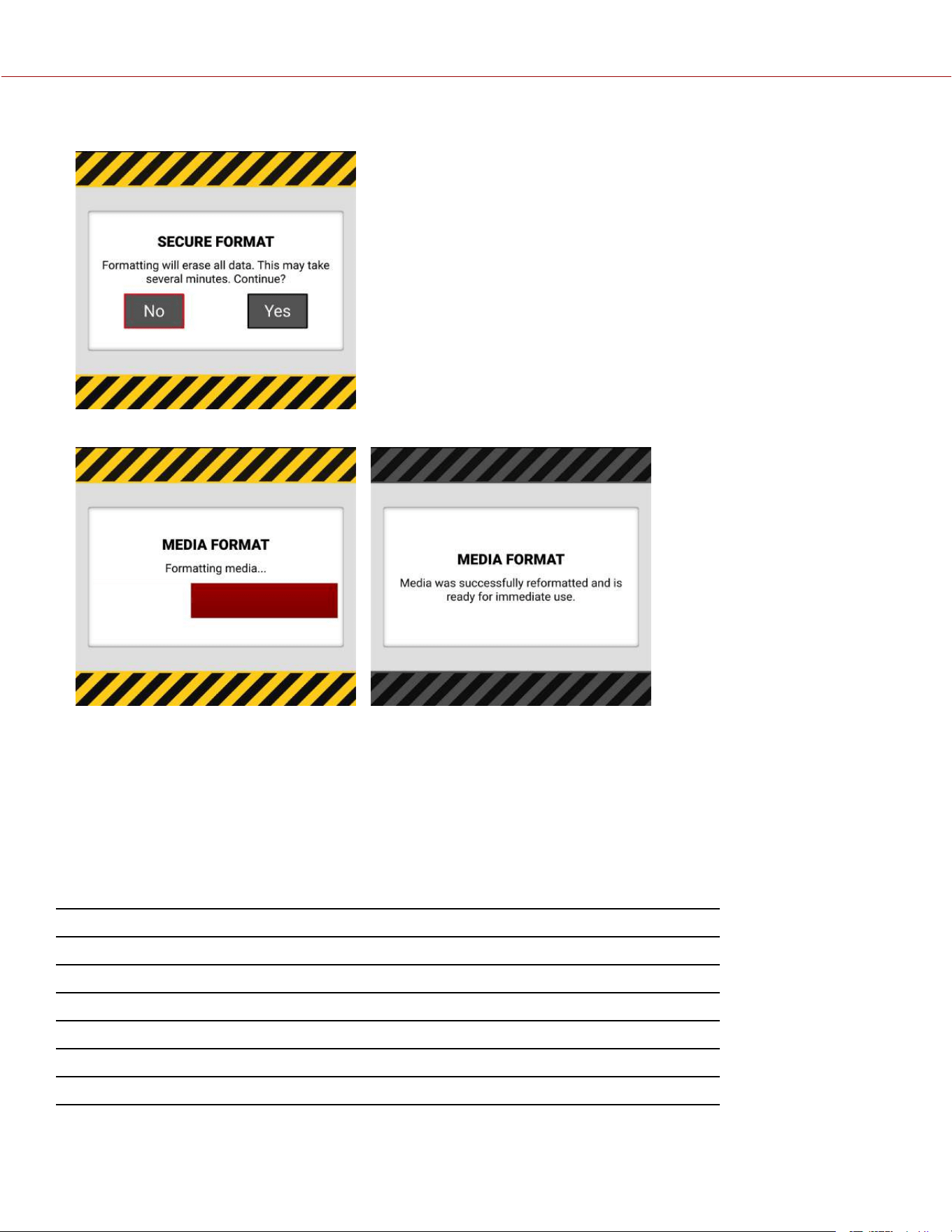
The confirmation message displays:
3. Tap Yes to begin formatting.
FORMATTING MEDIA ON A COMPUTER
RED recommends that you only format your media card from a computer when you cannot mount the media to the
camera (refer to Media Best Practices for more information).
MEDIA INFORMATION
Use the Media Info menu to display the media card information.
Media information includes the following:
SETTING DETAILS
Status Displays the media card status
Model Number Displays the media card model number
Serial Number Displays the media card serial number
Firmware Version Displays the media card firmware version
Percentage Remaining Displays the media card's remaining storage*
Time Remaining Displays the recording time remaining on the media card*
* with the current project settings
COPYRIGHT © 2023 RED.COM, LLC 955-0218, REV A | 218
KOMODO-X
®
OPERATION GUIDE
FILE SYSTEM
The camera formats the media card using the exFAT file system. Both Mac
®
and Windows
®
-based computers support
media cards with this system. Refer to the documentation for your operating system to determine whether there are any
limitations to its file system support.
CLIP NAMING CONVENTION
When you record a clip, the camera creates a unique name for the clip folder that uses the format described in the table
below:
ITEM DETAILS EXAMPLE
Camera ID The letter assigned to the camera (refer to Camera ID) A
Reel ID The reel number assigned to the media (refer to Reel Number) 004
Camera Position The camera position letter (A-Z) followed by three digits starting with 001 (refer
to Camera Position)
C001
Month Month that the clip is recorded (refer to Date / Time) 12
Day Day that the clip is recorded (refer to Date / Time) 04
Two Characters Two random alphanumeric characters generated by the camera to prevent any
possibility of duplicates
6M
.RDC Clip folder extension .RDC
For example, a sequence of clip folders within a media folder on Camera A may look like this:
A001_C001_12046M.RDC
A001_C002_1204CE.RDC
A001_C003_1204R5.RDC
CLIP METADATA
The following metadata is recorded for each frame of each clip:
Audio Data Lens Name, Brand, ID, Near Focus, Far Focus
Broadcast Wave File (BWF) Location
Clip LTC User Bits (3 32-bit word reg-dump from ISP)
Configuration, Camera Name, Network, Model,
Model ID, Serial Number
Media Serial Number
Production Name
Copyright
REDCODE
®
Date and GMT Reel
Filename Scene
Firmware Version Stereo Setup
Frame Guides Take
Jamsync Setting Timecode
Lens and Shutter Speed/Angle Parameters Unit
COPYRIGHT © 2023 RED.COM, LLC 955-0218, REV A | 219
KOMODO-X
®
OPERATION GUIDE
MEDIA BEST PRACTICES
This section describes best practices to ensure that your media cards continue to provide reliable storage and fast data
rates. Following these best practices may prevent your media card from becoming fragmented, which can lead to data
integrity errors.
The only files that should be saved from your computer to your media card are Preset files, Firmware Upgrade files,
and LUTs. DO NOT save other files, folders, or applications to your media.
DONOT back up your hard drive to the media card. When using a Mac, the system may ask if you want to back up
your files to the media card using Time Machine; DONOT use the media card as a backup disk.
DO NOT delete clips off of your media card using a computer. Delete clips only by formatting your media card in-
camera. For more information about formatting your media card, refer to Secure Format.
DO NOT format your media card using a computer, unless the media card cannot mount to the camera. For more
information, refer to Secure Format.
When ejecting the media card from a computer, ensure that the icon has completely disappeared from the Finder
window (Mac) or from Windows Explorer (Windows) before removing the media card. Sometimes, the pop-up saying
that the media card has ejected displays too early.
When the reader has a write-protect switch (such as the CFexpress Type B Media reader), it is recommended that
you set the card reader to write-protect when uploading clips to prevent connected devices from adding any
unwanted data to your media card.
INDEXING ON A MAC
NOTE: You can use the RED media reader with Write-Protect to prevent the Mac OS from indexing your media card.
Most newer versions of the Mac OS automatically index all external drives when you connect them. This includes when
you connect media cards.
Indexing makes the connection process take longer. While the media card connects to the Mac, DONOT remove the
card. Indexing writes hidden files to the media card. When you insert an indexed media card in the camera, it can take
the camera a while to recognize the hidden files and connect to the media card. While waiting for the media card to
connect, DONOT remove the card or turn off the camera. After the camera successfully connects to the media card,
perform a secure format to remove the hidden files. For more information, refer to Secure Format.
COPYRIGHT © 2023 RED.COM, LLC 955-0218, REV A | 220
KOMODO-X
®
OPERATION GUIDE
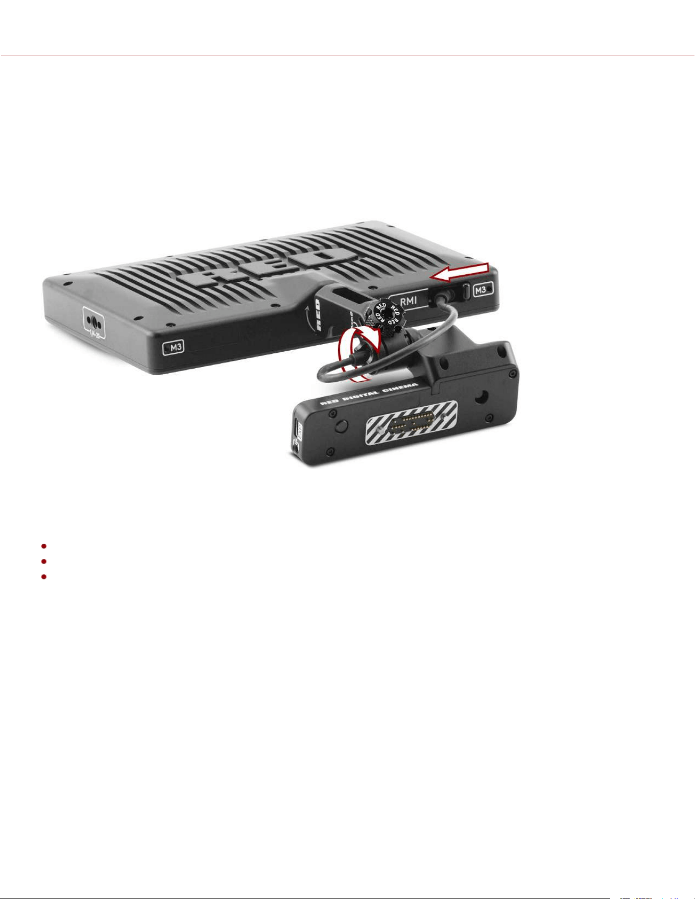
RED MONITOR INTERFACE CABLE
The DSMC3™ RED
®
Touch 7.0" LCD monitor includes a custom RED Monitor Interface (RMI) cable that provides
communication between the RMI and the monitor.
Where this cable attaches to the RMI and the monitor, there are special locking features that keep the cable from
accidentally detaching.
NOTE: The RMI cable is attached to the monitor at an angle, as shown in the image.
To unlock the cable locks, rotate the RMI cable lock and slide the monitor cable lock, as shown in the image:
NOTE: The USB-C-style DSMC3™ RMI cable is a custom-Pinned cable, which is not compatible with standard USB-C
cable ports (including the rear camera USB-C port). The EXP ports on the RMI are for future use and are not currently
supported.
Optional RED Monitor Interface (RMI) cables:
10" DSMC3™ RMI Cable
18" DSMC3™ RMI Cable
39" DSMC3™ RMI Cable
COPYRIGHT © 2023 RED.COM, LLC 955-0218, REV A | 221
KOMODO-X
®
OPERATION GUIDE
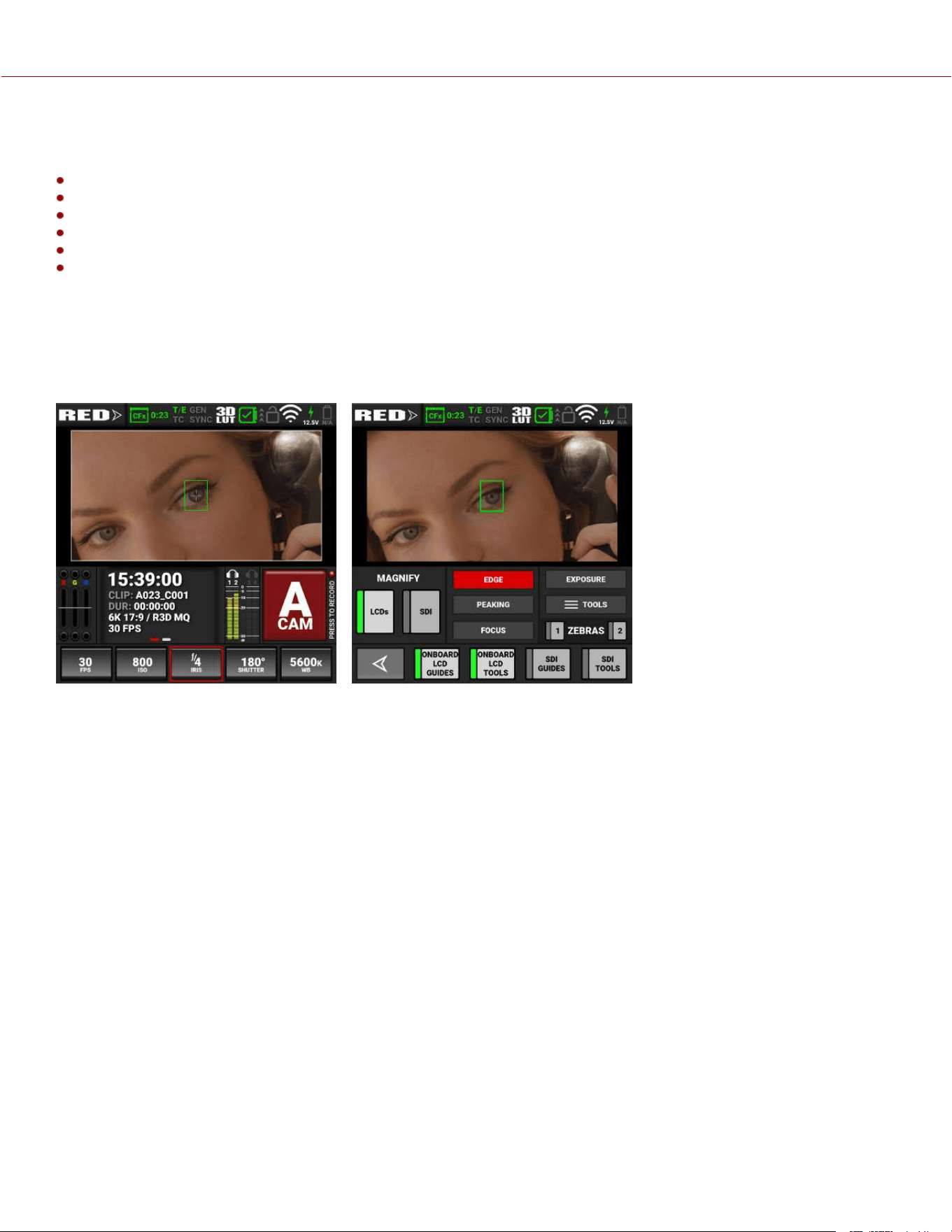
MONITORING
The camera provides several methods for monitoring the image. These monitoring methods include:
Onboard LCD touchscreen
DSMC3™ RED® Touch 7.0" LCD
SDI output to a monitor
RED Control over Wi-Fi to iOS or Android devices
USB-C to Ethernet adapter to a computer
1080 M-JPEG Live Stream
ONBOARD LCD TOUCHSCREEN
The Onboard LCD touchscreen provides a live image from the camera sensor. By using the Monitoring Tools menu, you
can display guides, exposure tools, focus tools, and a magnified image.
Tap on the Exposure meter to open the Monitoring tools.
In this example the LCD magnification and LCD guides are enabled. The Autofocus rectangle is also displayed.
COPYRIGHT © 2023 RED.COM, LLC 955-0218, REV A | 222
KOMODO-X
®
OPERATION GUIDE

SDI OUTPUT TO A MONITOR
The SDI port provides a 12G SDI signal, which allows you to view the camera image on a 4K SDI monitor at up to 60
fps.
Use the Monitor menu to select the settings for SDI output, Tools, and Guides (refer to Monitoring Menu
WARNING: Under certain circumstances, it is possible for an SDI connector to incur damage when connected to an
accessory and powered without using shielded cables. RED recommends only using high quality, shielded BNC cables
that are rated for 12G-SDI signals and only using shielded power cables for powering SDI accessories.
Make sure power is connected to the SDI accessory at all times before you connect the BNC to the camera.
Ungrounded power from SDI accessories can damage the camera’s SDI port. To avoid this possible damage, attach the
power source to the accessory before attaching it to the BNC cable. When using RED Approved Third Party battery
plates, unplug the BNC cable prior to hot swapping.
When possible, avoid using P-Tap (also known as D-Tap) cables to power accessories. To avoid damage when using P-
Tap/D-Tap, it’s imperative that the connect/disconnect sequence (below) is followed precisely.
BNC ATTACHMENT INSTRUCTIONS
When attaching SDI accessories:
1. Connect a power source to the SDI accessory; power on the SDI accessory.
2. Ensure a power source is connected to the camera. This ensures both are grounded prior to connecting the BNC.
The camera's power state does not have an impact on SDI attachment sequence.
3. Connect the BNC cable to the accessory, then to the camera.
When detaching an accessory mounted to an SDI output, ensure that you remove the BNC connection to the camera
before removing power to the SDI device:
1. Shutdown the SDI accessory.
2. Disconnect the BNC cable from the camera.
3. Disconnect the power source from the SDI accessory.
When you need to swap out a battery on an accessory mounted to the camera’s SDI port, you must:
1. Shutdown the SDI accessory.
2. Disconnect the BNC cable from the camera.
3. Replace the battery on the SDI accessory.
4. Connect the BNC cable to the camera.
5. Power on the SDI accessory.
For more information, refer to Preventing Damage to SDI Outputs.
COPYRIGHT © 2023 RED.COM, LLC 955-0218, REV A | 223
KOMODO-X
®
OPERATION GUIDE
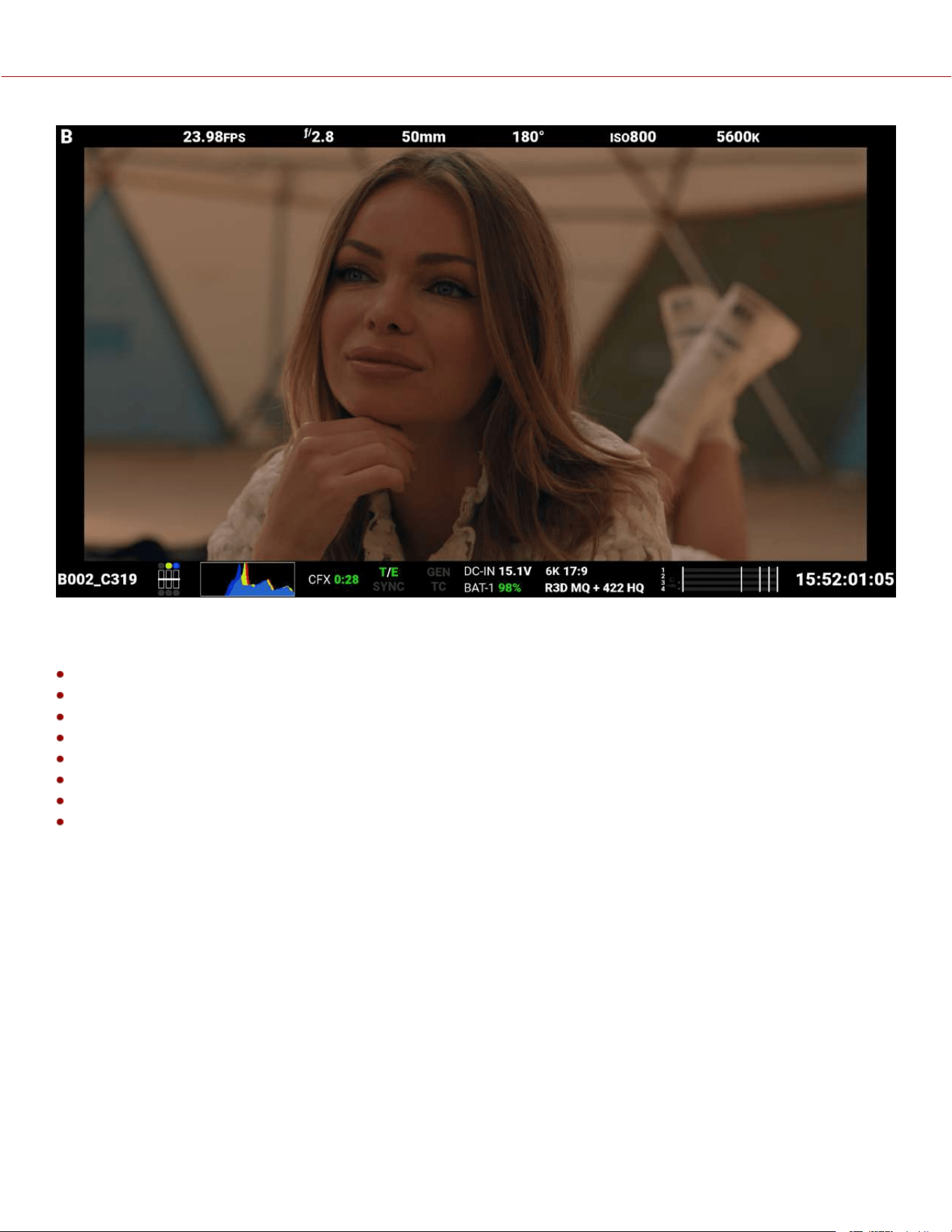
Figure: SDI monitor with SDI Advanced Mode enabled
SDI port specifications:
Integrated 12G-SDI with 6G-SDI, 3G-SDI, and 1.5G-SDI modes
12G-SDI: Up to 4096 × 2160 10-bit 4:2:2 for 60p
6G-SDI: Up to 4096 × 2160 10-bit 4:2:2 for 30p
3G-SDI: Up to 2048 × 1080 10-bit 4:2:2 for 60p
1.5G-SDI: Up to 2048 × 1080 10-bit 4:2:2 for 30p and 24p
SMPTE Timecode
HANC Metadata
24-bit 48 kHz Audio
You can enable or disable the image magnification, the focus and exposure tools, and the guides displayed on images
sent to the SDI monitor by using the Monitoring tools (refer to Monitoring Tools).
COPYRIGHT © 2023 RED.COM, LLC 955-0218, REV A | 224
KOMODO-X
®
OPERATION GUIDE
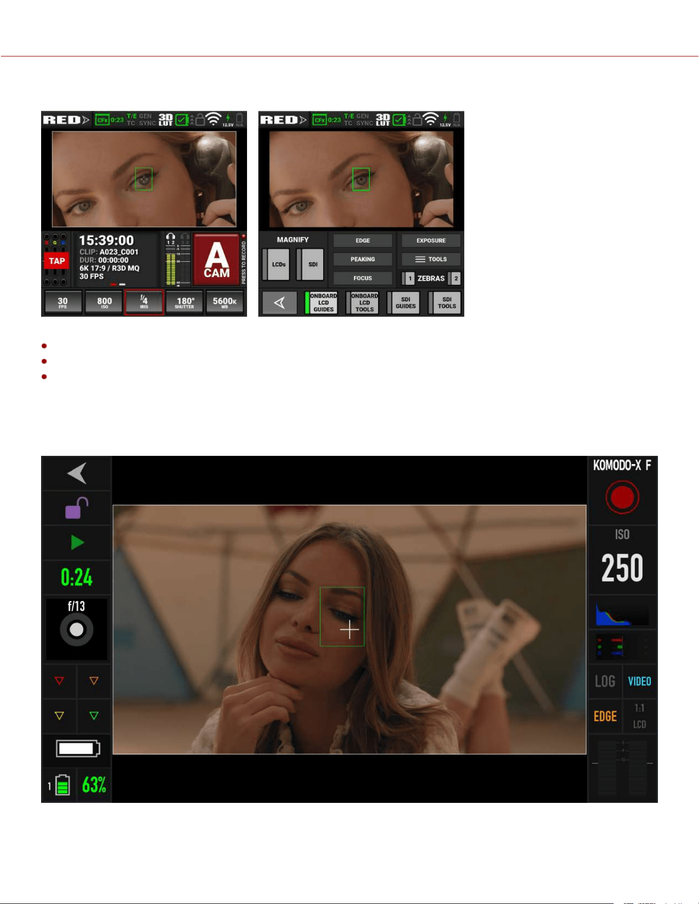
Tap on the Exposure meter to open the Monitoring tools.
You can enable the following monitoring tools on SDI:
Magnify
SDI Guides (refer to Guides)
SDI Tools (refer to Tools)
RED CONTROL
RED Control allows you to use Wi-Fi to connect to the camera and send monitor images to iOS and Android devices.
NOTE: You must enable live streaming under MENU > MONITORING > LIVE STREAM to enable the image feed.
Figure: RED Control phone monitor over Wi-Fi
COPYRIGHT © 2023 RED.COM, LLC 955-0218, REV A | 225
KOMODO-X
®
OPERATION GUIDE
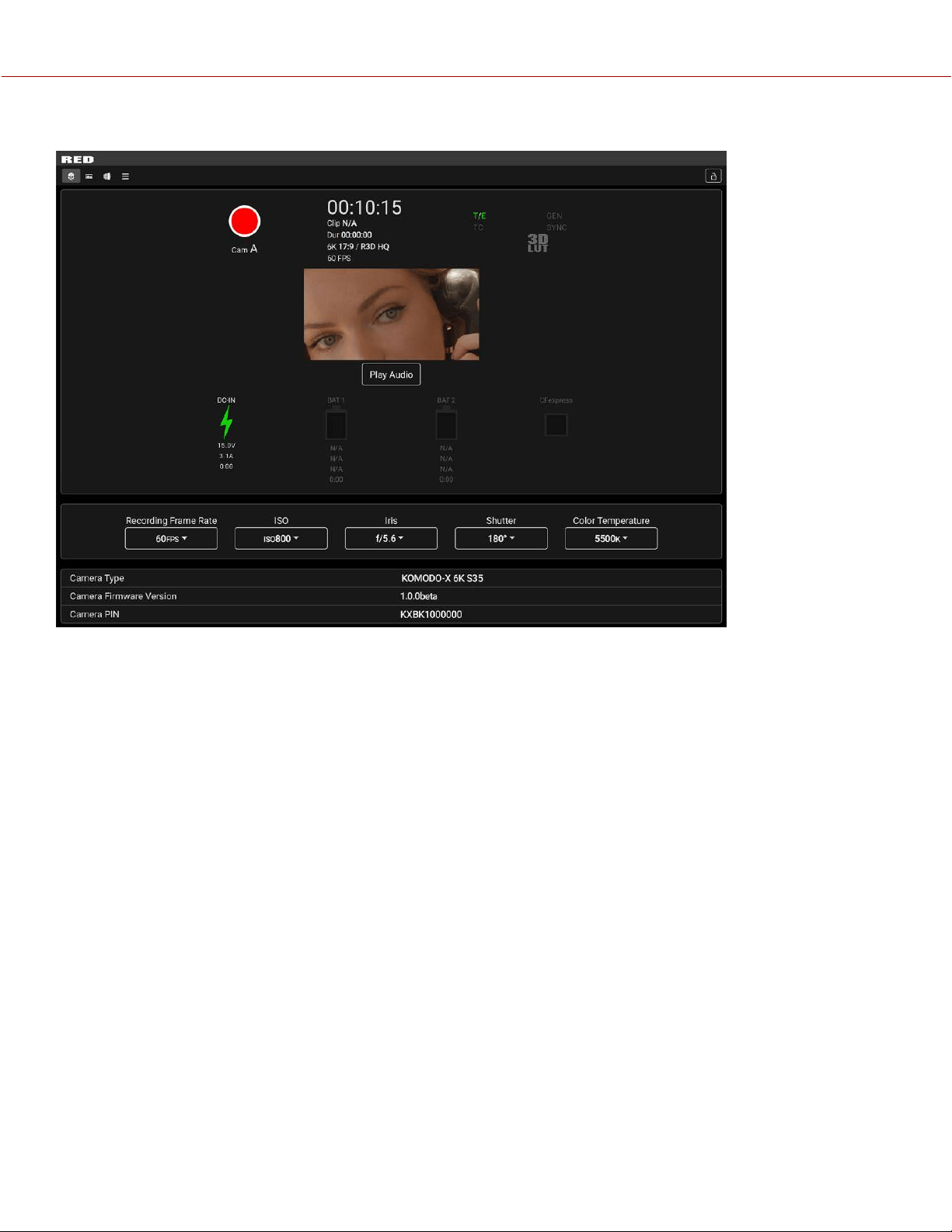
With the use of an Ethernet to USB-C adapter, you can also connect Ethernet devices.
Figure: USB-C Adaptor connected to an Ethernet web browser
You can add :9090 to the end of the URL in your browser to bring up an image-only feed for remote viewing.
NOTE: You must enable live streaming under MENU > MONITORING > LIVE STREAM to enable the image feed.
EXPOSURE
The camera offers multiple tools to determine the current image exposure levels and provides the tools to adjust the
exposure to the desired levels.
When using the R3D file format, you can correct color temperature and ISO settings at any time. The aperture and
exposure time however, are two of the parameters that you cannot corrected later in R3D files.
NOTE: ProRes file format burns in ISO and White Balance, and does not allow you to adjust these settings post-
recording like you can with the R3D format.
While the correct exposure is always an artistic decision, there are best practices for capturing the most dynamic range
while also allowing post production to preserve the intended image information.
The goal is to reduce clipping in the bright and dark parts of the image as much as possible. Otherwise the sensor
information is lost in the overexposed and underexposed areas.
The primary tool for determining the exposure levels is the histogram. It shows the exact luminance levels of the red,
green, and blue pixels after you apply the ISO and White Balance settings. Monitors have their own color gamuts and
brightness levels which makes the monitor less than optimal for determining the camera's exposure levels.
This camera includes a full Histogram and a simple RGB raw pixel exposure meter, which allows you to determine
proper exposure regardless of the set ISO or camera look (for more information refer to Onboard LCD Touchscreen).
COPYRIGHT © 2023 RED.COM, LLC 955-0218, REV A | 226
KOMODO-X
®
OPERATION GUIDE
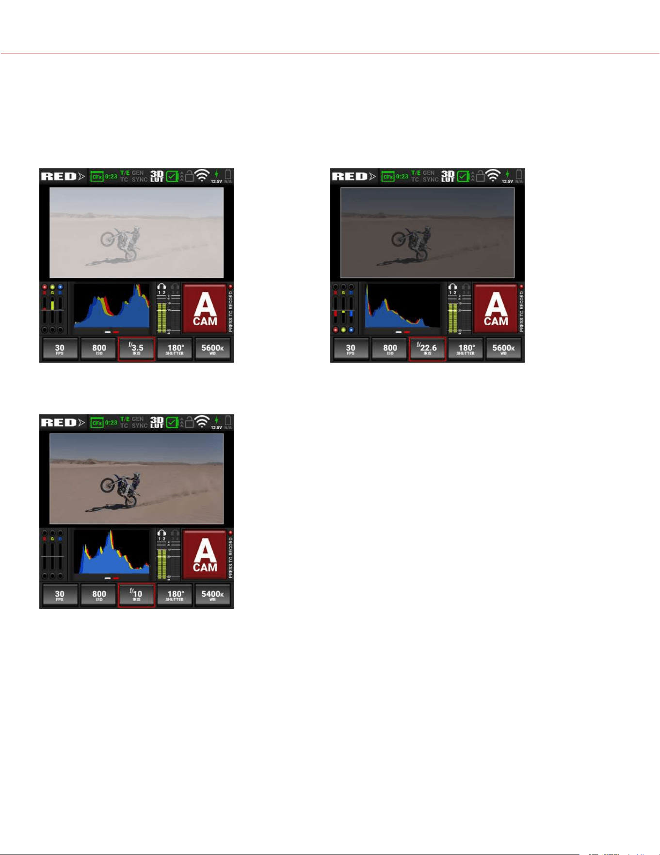
The full histogram provides information about how the brightness is distributed in the image. This allows you to see how
close a scene is to clipping in the light and dark areas, which makes it easy to choose aperture, exposure, and ND
filters solutions accordingly.
Example of overexposure
with histogram and exposure meter:
Example of underexposure
with histogram and exposure meter:
Example of a balanced exposure
with histogram and exposure meter:
COPYRIGHT © 2023 RED.COM, LLC 955-0218, REV A | 227
KOMODO-X
®
OPERATION GUIDE
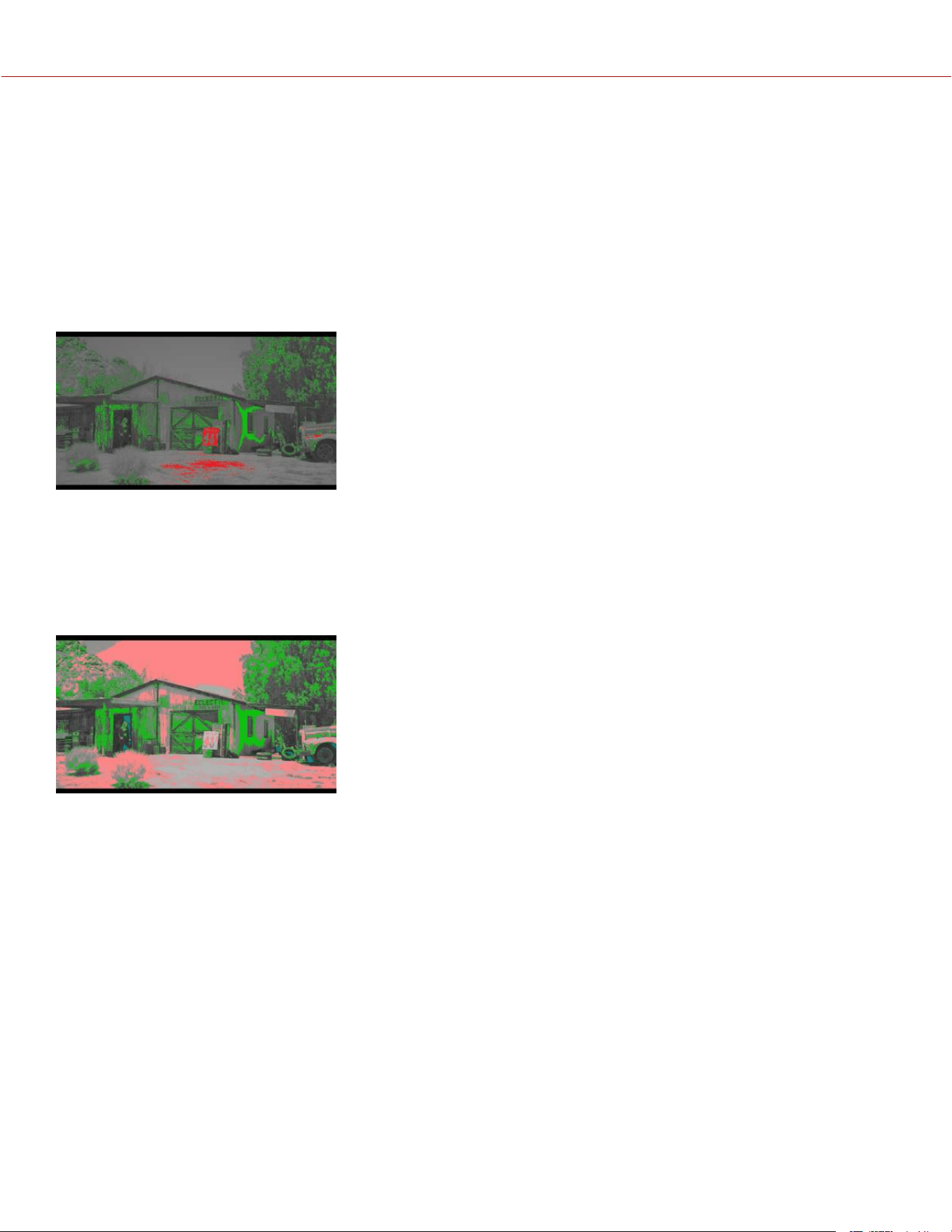
FALSE COLOR EXPOSURE TOOLS
While the histogram provides information about the brightness distribution and clipping of the image, it does not show
you the areas in the image that are near, or that have reached, clipping. For this, the camera provides image overlays
that provide false colors to indicate precise exposure levels.
FALSE COLOR EXPOSURE MODE
The False Color Exposure mode overlay provides information where the image is close to clipping or already clipping in
the highlights (red), midtones (green), and shadows (purple). For more information, refer to False Color Exposure Mode.
Example of Exposure Mode:
FALSE COLOR VIDEO MODE
The False Color Video mode provides more gradual information about the brightness in different parts of the image. This
is helpful when you want to expose skin color at the right level, while ignoring the fact that backgrounds might be
overexposed or underexposed (refer to False Color Video Mode).
Example of Video Mode:
FALSE COLOR GIO SCOPE MODE
Gio Scope mode displays a color overlay on top of a desaturated RAW sensor image, identifying 16 increments within
the dynamic range of the sensor. The RGB settings (color temperature, ISO, LUT, etc.) are not used by this mode.
Each number (1 to 16) indicates a different increment of dynamic range. Number 16 represents the top increment, and is
broken up into 1/8th sub-increments to show highlight roll-off. Each 1/8th increment is represented by a different shade
of red, ranging from light red (less light) to dark red (most light, clipping).
COPYRIGHT © 2023 RED.COM, LLC 955-0218, REV A | 228
KOMODO-X
®
OPERATION GUIDE
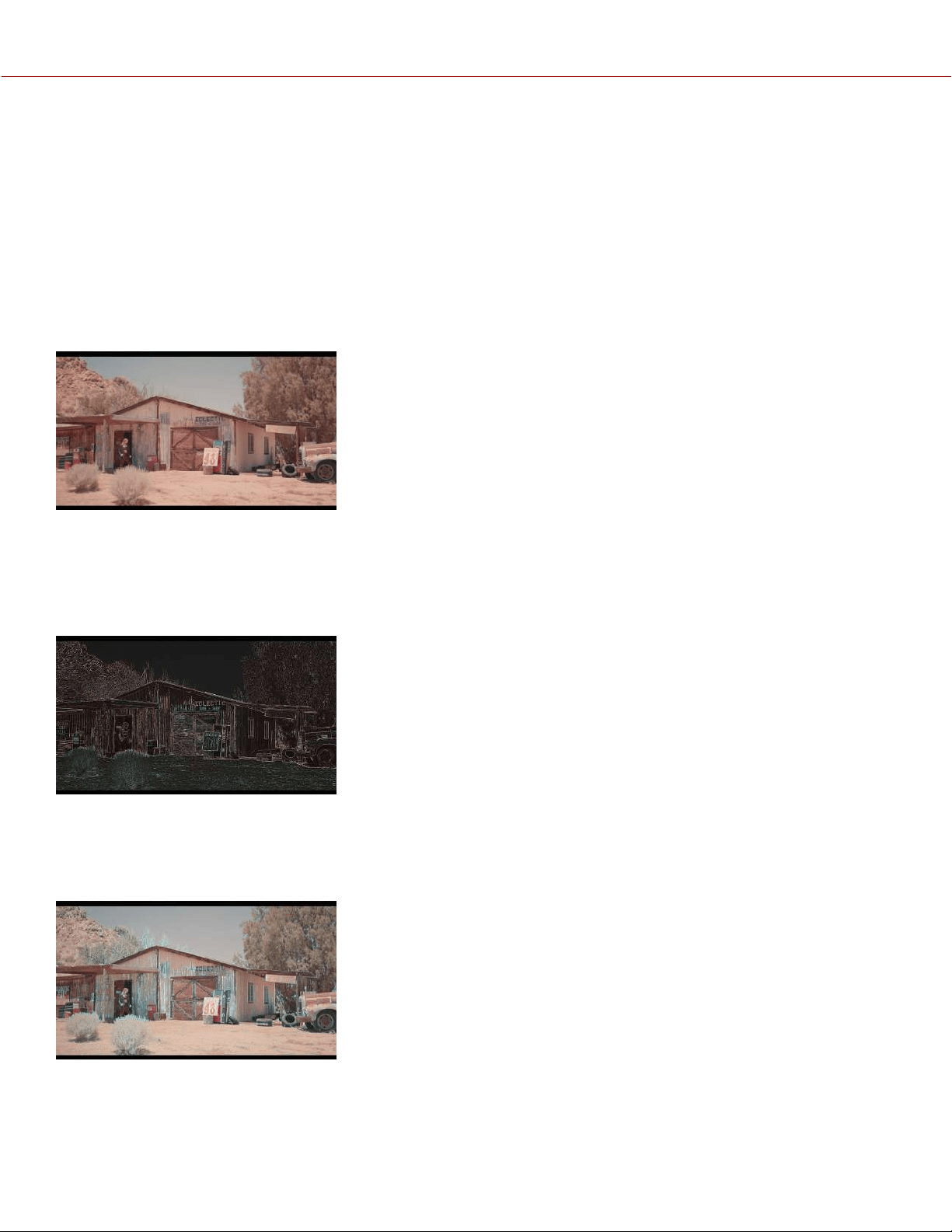
FOCUS
Focus, like Exposure and Recording Frame Rate is a property that cannot be fixed easily in post-production. To make
sure the camera is focused correctly when you begin recording, it is important to rely on focus tools that do not rely on
the visibility on the LCD Touchscreen or a monitor.
The camera interface includes the focus tools you can use to reach the desired image focus (refer to Peaking).
FOCUS PEAKING MODE
The Focus Peaking mode applies a sharpening filter to the image that emphasizes edges of the subject in focus.
Example of Focus Peaking:
EDGE PEAKING MODE
The Edge Peaking mode hides the image and only shows the edges. This provides the best visual representation of the
subject that is currently in focus.
Example of Edge Peaking mode:
PEAKING PEAKING MODE
The Peaking Peaking mode emphasizes the edges, and it also highlights them by using a selectable color.
Example of Peaking Peaking mode:
COPYRIGHT © 2023 RED.COM, LLC 955-0218, REV A | 229
KOMODO-X
®
OPERATION GUIDE
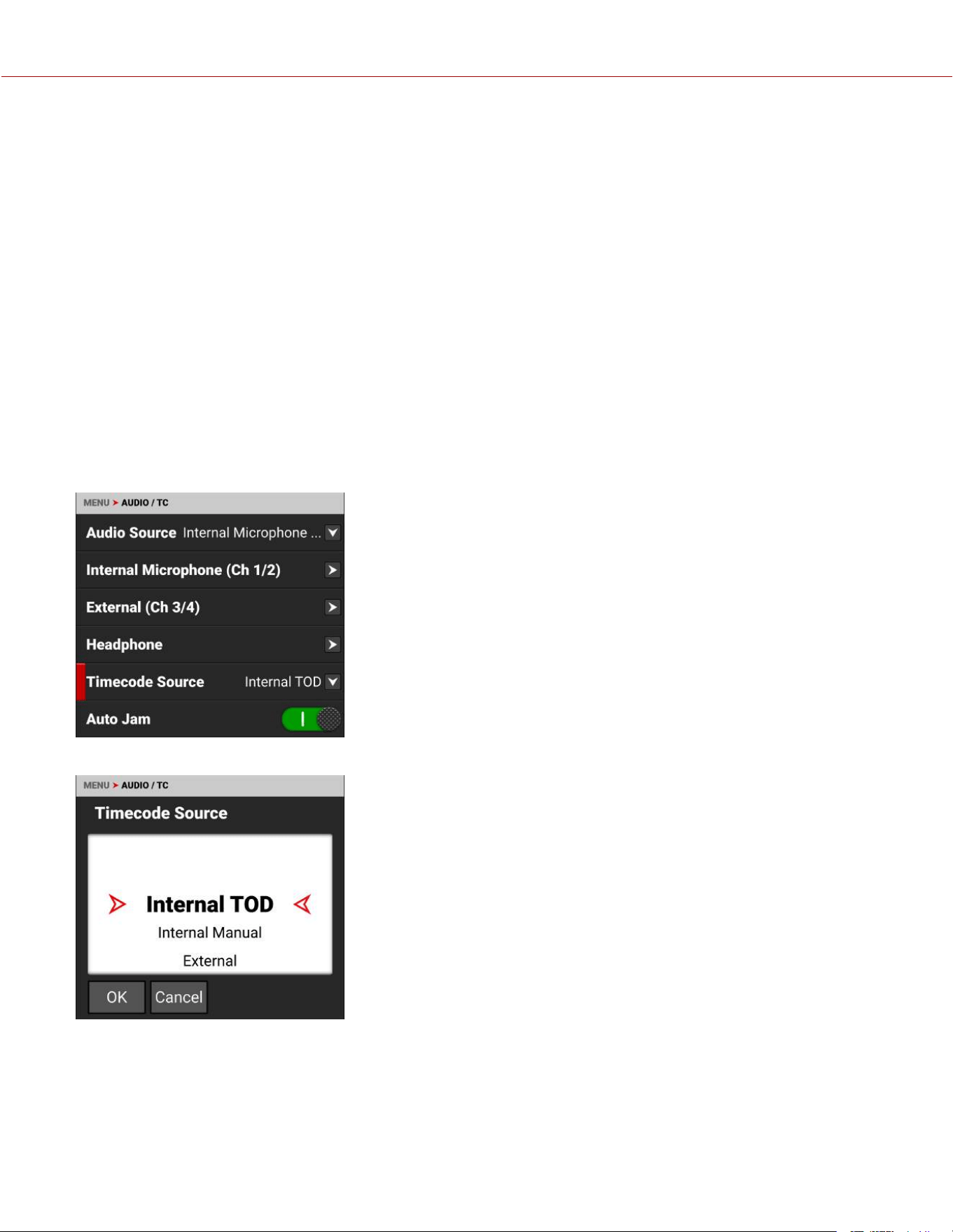
TIMECODE
Timecode provides a mechanism to reference frames from the camera's recorded clips to other devices like cameras
and audio recorders. Some devices can also gather other data like lens metadata or camera orientation that is
referenced by Timecode to merge the data back together in post-processing.
KOMODO provides two separate Timecode concepts: Time of Day (TOD) and Edgecode. Both TOD and Edgecode are
stored in the R3D file. The user can select which Timecode displays on the Onboard LCD Touchscreen by setting the
preference in Timecode Display Mode.
TIME OF DAY
TOD Timecode reflects the time and date the camera recorded each frame. KOMODO synchronizes the TOD Timecode
to an external Timecode generator (when one is connected to the Extension Port) or synchronizes to the internal real-
time clock of the camera.
SETTING UP TOD TIMECODE
To set up TOD Timecode on the camera, perform the following:
1. Open the Audio / Timecode menu: MENU > AUDIO / TC:
2. Select Timecode Source. The Timecode Source menu opens:
3. Select Internal TOD to use the camera's internal real time clock, select Internal Manual to specify a starting time for
the internal clock, or select External to use an external Timecode generator connected to the Extension Port.
COPYRIGHT © 2023 RED.COM, LLC 955-0218, REV A | 230
KOMODO-X
®
OPERATION GUIDE
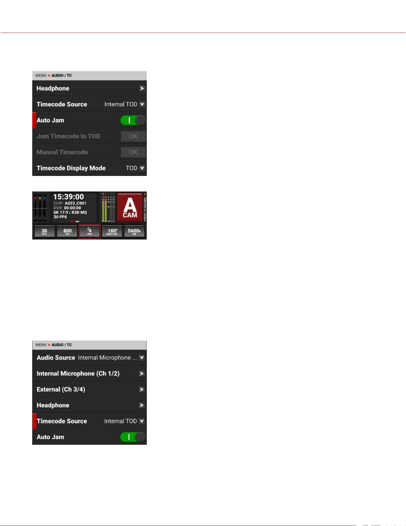
4. When you select Internal TOD, you can use the Auto Jam switch to enable the camera to automatically synchronize
the Timecode to the camera's internal clock.
The camera displays the Timecode on the Onboard LCD Touchscreen
NOTE: The timecode is reset when the camera is turned off, unless an external power source remains connected and
powered.
EDGECODE
Edgecode only advances while the camera is recording frames. Each frame is sequential. When the media is replaced,
the new media starts the timer over. You can set the Edgecode timer manually by using the Secure Format menu.
SETTING UP EDGECODE TIMECODE
To set up Edgecode Timecode on the camera, perform the following:
1. Open the Audio / Timecode menu: MENU > AUDIO / TC:
COPYRIGHT © 2023 RED.COM, LLC 955-0218, REV A | 231
KOMODO-X
®
OPERATION GUIDE
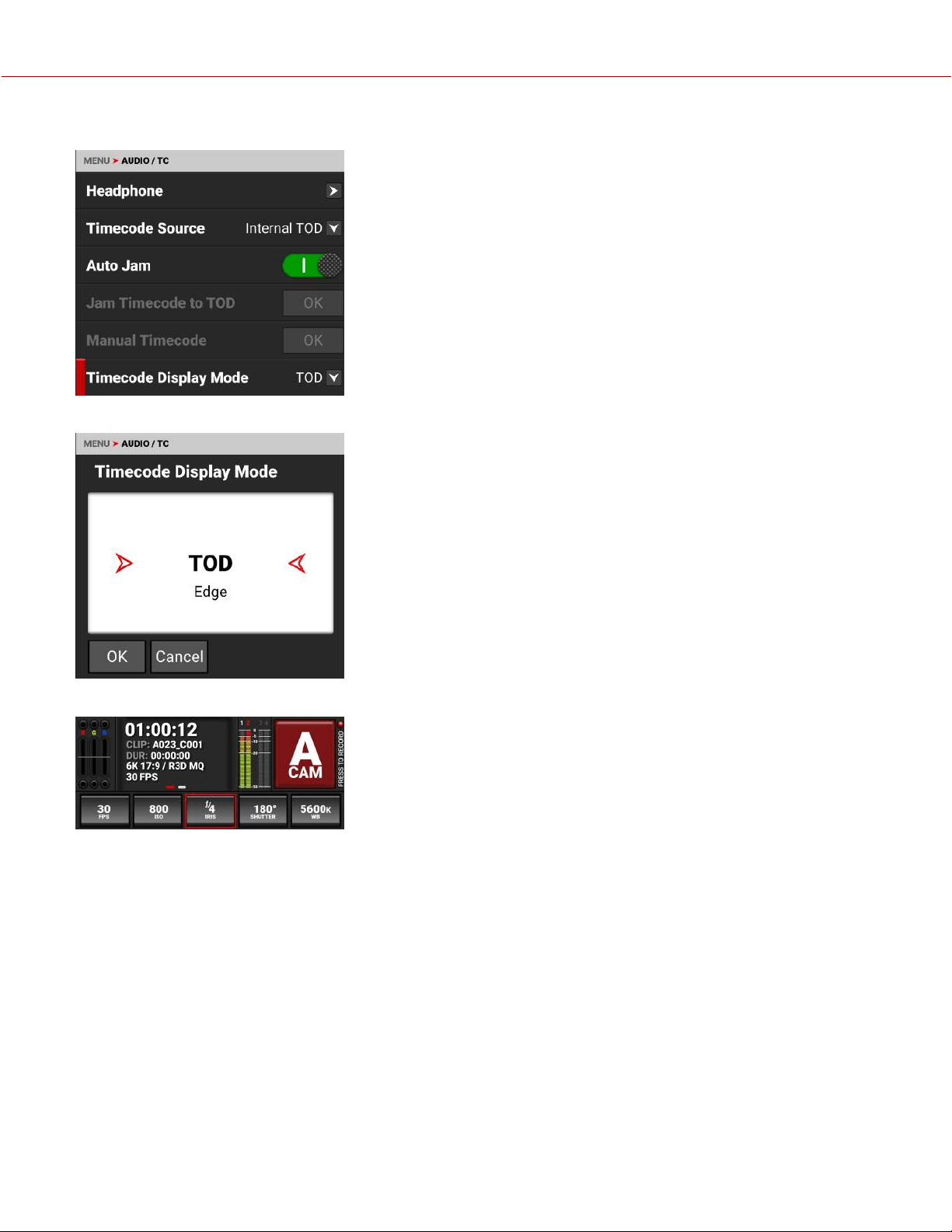
2. Swipe the touchscreen up to scroll down to Timecode Display Mode:
3. Select Timecode Display Mode. The Timecode Display Mode menu opens:
4. Select Edge and tap OK to use Edgecode. The camera displays the Edgecode on the Onboard LCD Touchscreen
COPYRIGHT © 2023 RED.COM, LLC 955-0218, REV A | 232
KOMODO-X
®
OPERATION GUIDE

ZEBRA MODES
Use Zebra mode to enable and adjust the upper and lower values for two (2) independent zebra indicators. Use Zebra 1
for highlight exposure, and use Zebra 2 for mid-tones or shadows. Zebras are disabled by default.
For more information, refer to the Exposure with RED Cameras: False Color and Zebra Tools article, available at
www.red.com/red-101/exposure-false-color-zebra-tools.
ENABLING THE ZEBRA 1 INDICATOR
1. Go to MENU > MONITORING > TOOLS and select ZEBRA 1.
2. Set a Low IRE of 98.
3. Set a High IRE of 100.
Areas of the image exposed within the IRE range are indicated by red diagonal lines at –45°.
The default settings are Low IRE = 98 and High IRE = 100.
ENABLING THE ZEBRA 2 INDICATOR
1. Go to MENU > MONITORING > TOOLS and select ZEBRA 2.
2. Set a Low IRE of 41.
3. Set a High IRE of 48.
Areas of the image exposed within the IRE range are indicated by green diagonal lines at 45°.
The default settings are Low IRE = 41 and High IRE = 48.
ZEBRA OVERVIEW
Zebra is a specialty mode that is capable of showing up to two customized overlays with arbitrary IRE ranges. Unlike
the other two modes, Zebra indicators appear as diagonal stripes, they are fully configurable, and they have the
advantage of preserving a full-color base image.
With traditional video cameras, many used a single zebra to indicate highlight detail. It would often be set at 70% (70
IRE), in part because this is where a white piece of paper would begin to have minimal texture when rendered using a
typical contrast curve. Skin tones or skies would be exposed to appear just darker or brighter than these lines. If
enabled, a second zebra would typically indicate either mid-tones or shadows. For deep shadows, you can set the
second indicator to below 10% intensity or 10 IRE, and set the first indicator to highlights above 85 IRE.
However, as with other IRE-based modes, Zebra mode is only applicable for the current ISO settings (such as with SDI
output), not for the raw image data. If anything is changed in post-production, the indicators won't be representative of
the final output tones. In those situations, Zebra mode is more of a preview and output brightness tool than an exposure
tool.
COPYRIGHT © 2023 RED.COM, LLC 955-0218, REV A | 233
KOMODO-X
®
OPERATION GUIDE
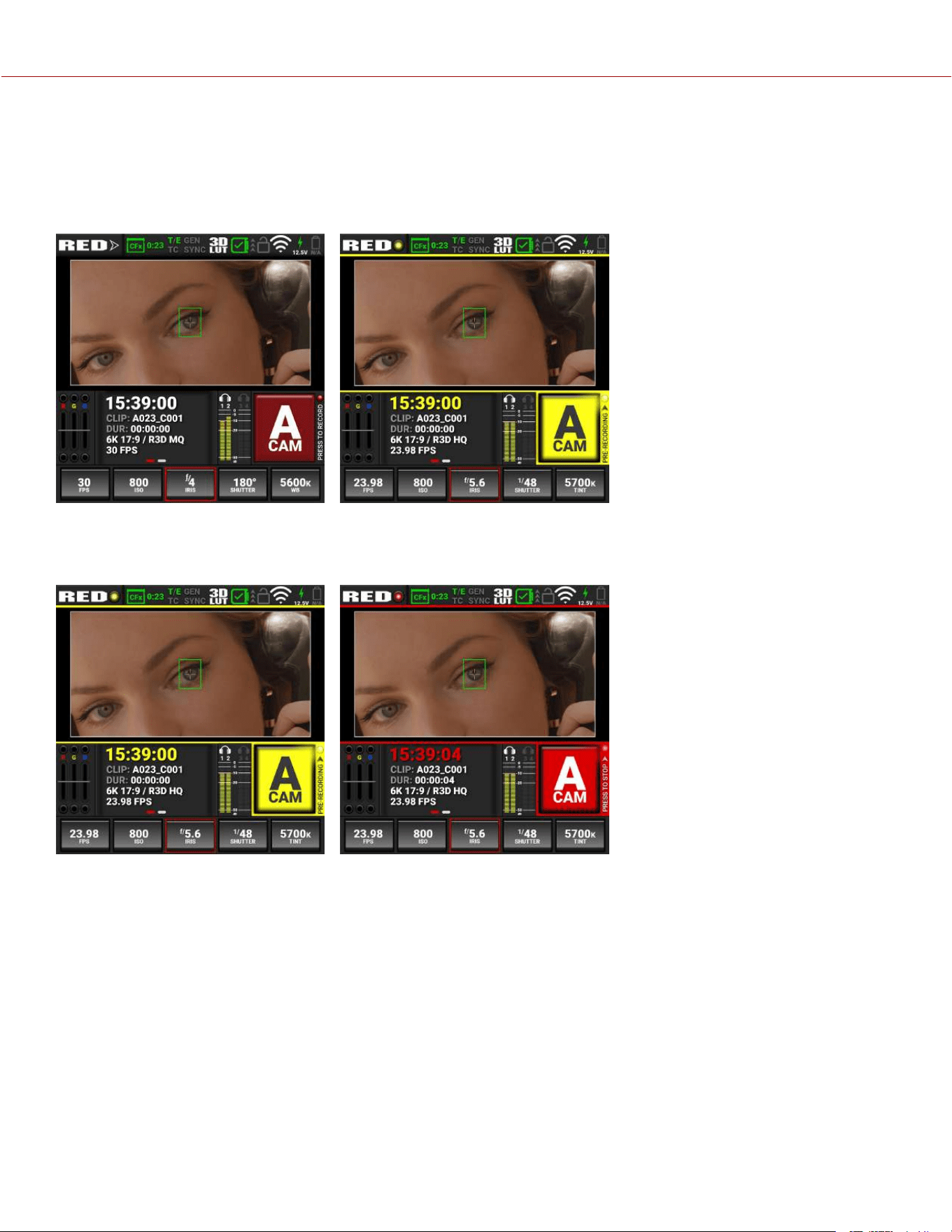
PRE-RECORDING CONTENT
This section explains how to use the Pre-Record feature.
To start pre-recording, press the Record button.
The LCD changes from the Ready appearance to the Pre-Record appearance:
Press the Record button again to start recording.
When you start recording, the appearance of the LCD changes from the Pre-Record appearance to the Record
appearance:
The camera adds the Pre-Record clip to the beginning of your recording.
You can touch and hold the record button on the Onboard LCD to stop Pre-Record. You can also assign physical
buttons on the camera to Pre-Record Stop to stop and erase the current Pre-Record segment, or Pre-Record Toggle to
completely disable or enable the Pre-Record function.
For information about enabling and configuring Pre-Record, refer to Pre-Record.
COPYRIGHT © 2023 RED.COM, LLC 955-0218, REV A | 234
KOMODO-X
®
OPERATION GUIDE
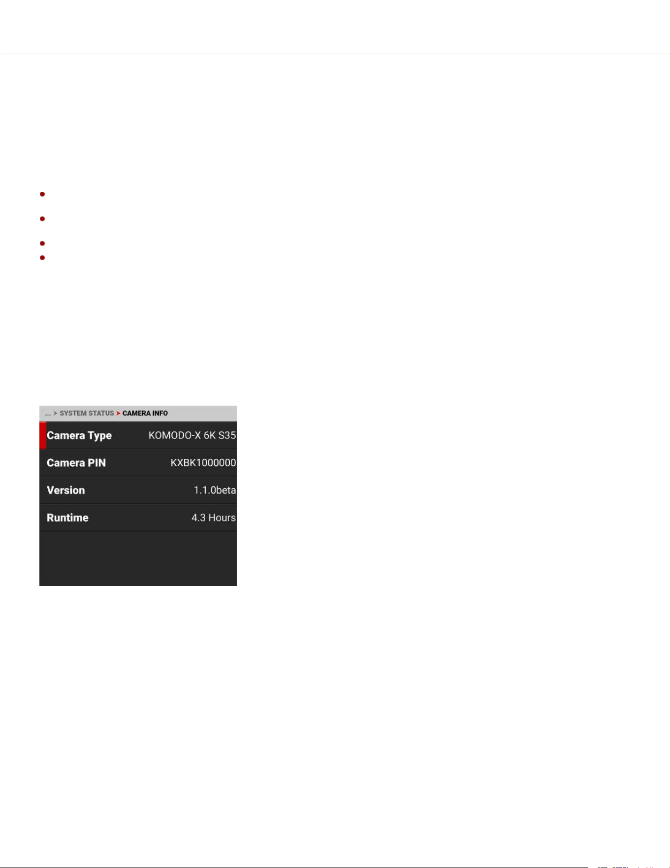
CALIBRATING THE SENSOR
Sensor calibration is a process during which the camera optimizes image quality by ensuring that pixel sensitivity
remains consistent throughout the sensor.
WHEN TO CALIBRATE THE SENSOR
Calibration is recommended:
When shooting in an environment where the temperature is significantly different (+/- 30° F...) from the current
calibration. The T in the T/E Status Bar indicator will turn yellow (refer to Status Bar for more information)
After an extreme change in exposure time (+/– 1/2 sec). The E in the T/E Status Bar indicator will turn yellow (refer to
Status Bar for more information)
After each firmware upgrade
When you have any image quality concerns
UPGRADING THE FIRMWARE
You can receive the best performance from your camera by installing the latest firmware. Make a habit of frequently
visiting RED Downloads at www.red.com/downloads to check for new versions of camera firmware, updated operation
guides, and post-production software.
VERIFYING THE FIRMWARE VERSION
To view the firmware version that is currently installed on your camera, open Menu > System Settings > System
Status > Camera Info:
Version displays the currently installed camera firmware. A higher number
reflects a newer release.
UPGRADING THE FIRMWARE
Install the most recent firmware. Unless otherwise specified in the release notes, you do not need to upgrade to any
firmware in between your current version and the most recent version available online.
You can upgrade the firmware by using an upgrade folder copied to a media card, or you can upgrade over an Ethernet
connection.
NOTE: You must calibrate the sensor after upgrading the camera. For more information, refer to Calibrating the Sensor.
COPYRIGHT © 2023 RED.COM, LLC 955-0218, REV A | 235
KOMODO-X
®
OPERATION GUIDE
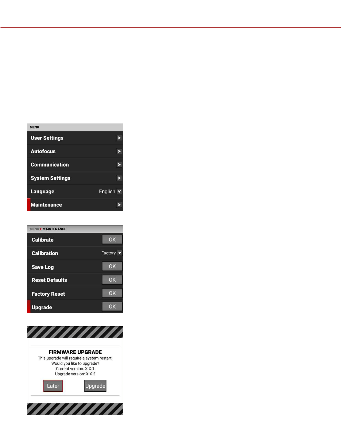
UPGRADING FROM A MEDIA CARD
1. Download the most recent firmware for your camera from RED Downloads at www.red.com/downloads.
2. Unzip the firmware zip file.
3. In the unzipped folder, navigate to the upgrade folder.
4. Copy the upgrade folder and its contents to the root level of the CFexpress media card directory.
5. Unmount the CFexpress media card from your computer and remove the media card from the media reader.
6. Insert the CFexpress media card in the camera. The camera detects the upgrade folder and prompts you to upgrade
the firmware.
7. From the camera UI, navigate to Menu > Maintenance.
8. From the Maintenance menu, navigate down to Upgrade and tap OK.
The Firmware Upgrade confirmation screen displays:
COPYRIGHT © 2023 RED.COM, LLC 955-0218, REV A | 236
KOMODO-X
®
OPERATION GUIDE
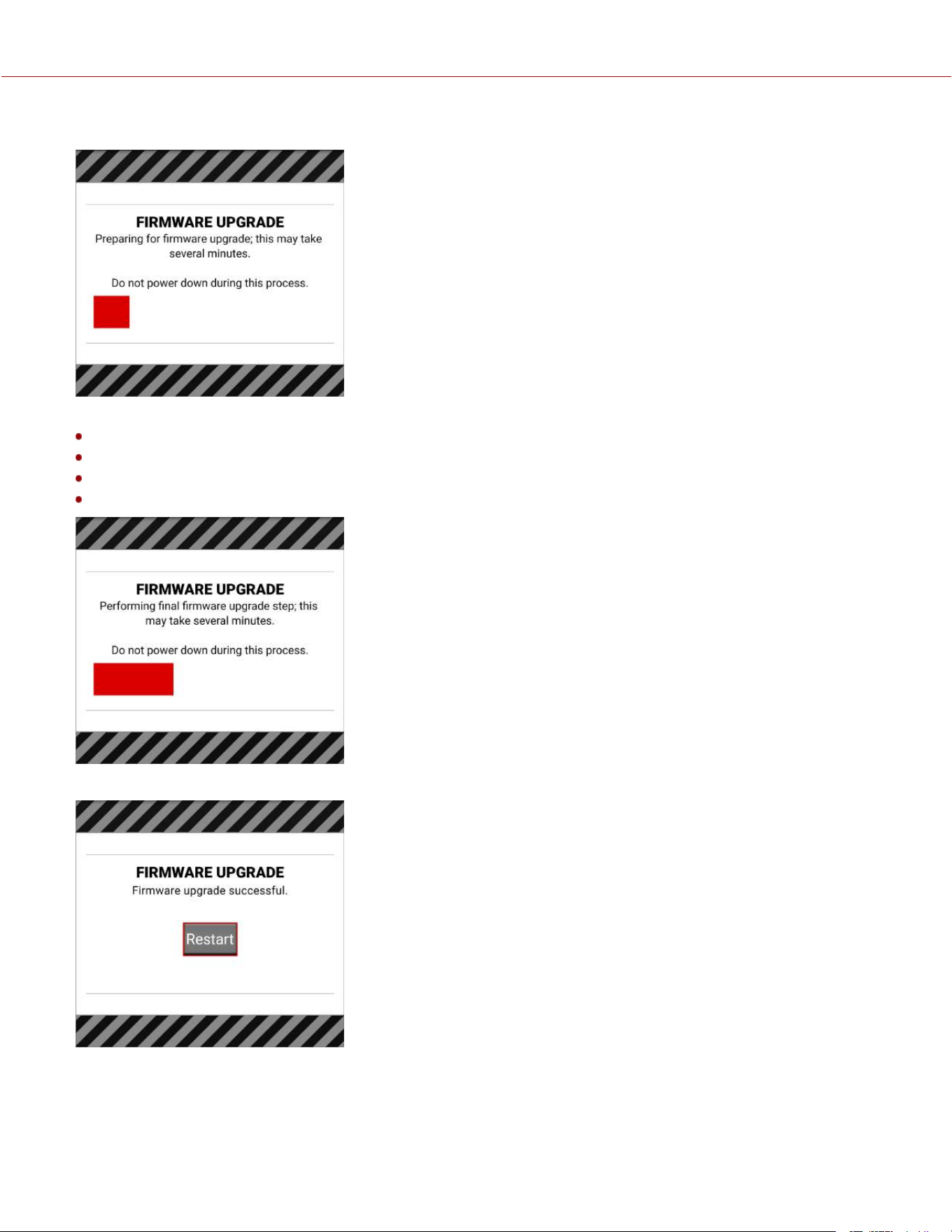
9. Tap Upgrade to confirm. The Firmware Upgrade progress screen displays:
During the upgrade, the fans run at high speed and the following occurs:
The camera displays the SHUTTINGDOWN screen and reboots
The camera restarts and displays the UPGRADING screen
The camera displays the INITIALIZING screen
The camera displays the FIRMWAREUPGRADE progress screen:
The Firmware Upgrade success message screen displays with a RESTART button:
10. Tap Restart. The camera displays the SHUTTINGDOWN screen and reboots again.
COPYRIGHT © 2023 RED.COM, LLC 955-0218, REV A | 237
KOMODO-X
®
OPERATION GUIDE
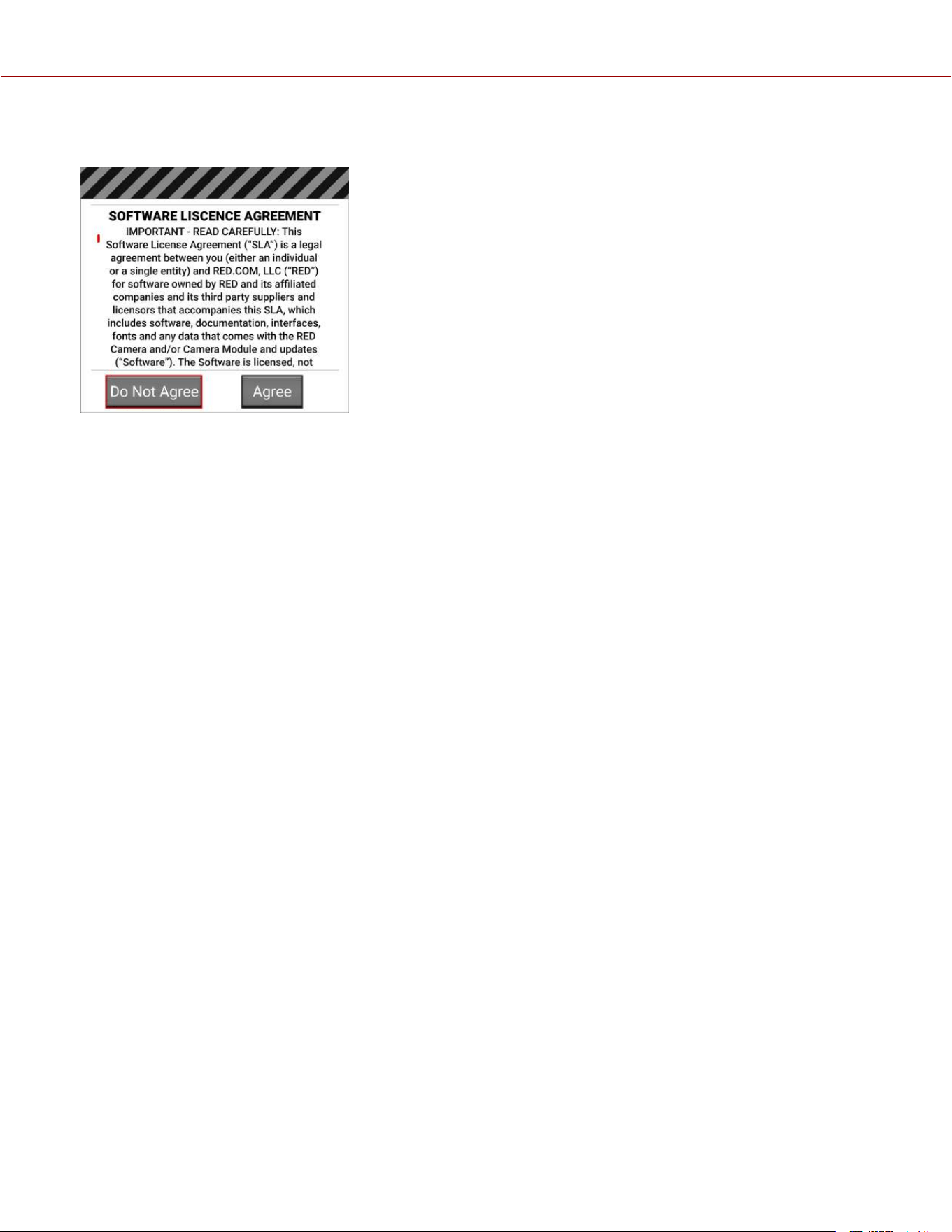
11. The camera restarts displaying the Start screen, the INITIALIZING screen, and then the Software License
Agreement (SLA) displays:
12. Tap Agree. If you do not agree to the SLA, the camera cannot be used. The SLA continues to display until it is
accepted.
13. Recalibrate the camera before recording. Refer to the Calibration section and Calibrating the Sensor for more
information.
UPGRADING THE DSMC3™ RED
®
TOUCH 7.0" LCD FIRMWARE
You can receive the best performance from your DSMC3™ RED
®
Touch 7.0" LCD monitor by installing the latest
firmware. Make a habit of frequently visiting RED Downloads at www.red.com/downloads to check for new versions of
DSMC3™ RED
®
Touch 7.0" LCD firmware, updated operation guides, and post-production software.
UPDATING AUTOMATICALLY THROUGH THE CAMERA
When a newer firmware is detected on the camera, the DSMC3™ RED
®
Touch 7.0" LCD will prompt you on each boot
to update the monitor. Follow the on-screen prompts to update the monitor.
UPDATING MANUALLY THROUGH SmallHD
When a newer monitor firmware is available directly from SmallHD, there are two ways you can upgrade the DSMC3™
RED
®
Touch 7.0" LCD firmware.
UPGRADE DIRECTLY FROM THE DSMC3™ RED
®
TOUCH 7.0" LCD
1. Download the DSMC3™ RED
®
Touch 7.0" LCD upgrade .bin file directly from downloads.smallhd.com, to the root
directory of a 2, 4, 8, or 16 GB SD card.
2. Insert the SD card in the monitor.
3. From the DSMC3™ RED
®
Touch 7.0" LCD Settings Panel, initiate the update.
UPGRADE THROUGH THE CAMERA
1. Download the DSMC3™ RED
®
Touch 7.0" LCD upgrade .bin file directly from downloads.smallhd.com.
2. Create a folder named “smallhd” on the root of the camera’s CFexpress media card.
3. Copy the firmware file to the "smallhd" folder.
4. Insert the CFexpress card in the camera, and initiate the update through the Settings Panel of the DSMC3™ RED
®
Touch 7.0" LCD.
NOTE: This method requires that the monitor be on at least firmware version 5.0.0 to work. If the monitor is on OS4,
use the Directly from the DSMC3™ RED
®
Touch 7.0" LCD firmware upgrade method.
COPYRIGHT © 2023 RED.COM, LLC 955-0218, REV A | 238
KOMODO-X
®
OPERATION GUIDE

SYSTEM MAINTENANCE
All RED products are designed for rugged durability, but precision instruments demand proper care. Follow the
instructions in this section to clean, maintain, and store your devices.
WARNING: DO NOT rinse or immerse the camera or other accessories in water. Keep dry at all times.
WARNING: DO NOT use soaps, detergents, ammonia, acetone, alkaline cleaners, abrasive cleaning compounds, or
solvents. These substances may damage lens coatings and electronic circuitry.
WARNING: DO NOT use an excess of cleaning solution.
WARNING: DO NOT reuse swabs or wipes.
WARNING: DO NOT attempt to clean the sensor or optical cavity for any reason. If the sensor becomes dirty, submit a
Support ticket at https://support.red.com.
WARNING: DO NOT attempt to modify, dismantle, or open the camera, lens, or other accessory as doing so may
expose you to electric shock and serious injury. There are no user-serviceable parts inside. Alteration or repairs made to
the camera or accessories, except by a RED authorized service facility, voids all warranties.
WARNING: Use caution with compressed air and gas dusters, since the high pressure, oily residue, cold air,
particulates, and moisture may cause damage. You may use a filtered, non-residue gas duster to clean non-critical
areas, such as around the fans and other recesses on the exterior of the camera. Damage to the camera or other
components of the camera system caused by using compressed air or gas dusters is not covered under warranty.
WARNING: DO NOT use compressed air and gas dusters on the sensor or on any optics.
WARNING: DO NOT use compressed air and gas dusters on or around the integrated microphones on the front of the
camera.
EXTERIOR SURFACES
Use a filtered, non-residue gas duster to clean non-critical areas, such as around the fans and other recesses on the
exterior of the camera.
Clean with a dry lint-free cloth. When cleaning your camera and accessories, remember that the devices are not
waterproof and moisture can damage electronic circuitry.
STORAGE
WARNING: DO NOT store the camera or accessories in any place with extreme temperatures, direct sunlight, high
humidity, severe vibration, or strong magnetic fields.
COPYRIGHT © 2023 RED.COM, LLC 955-0218, REV A | 239
KOMODO-X
®
OPERATION GUIDE
ONBOARD LCD SCREEN
This section explains how to clean the Onboard LCD screen.
APPROVED LCD SCREEN CLEANERS
Use only the following products to clean the Onboard LCD screen:
Ionized rubber air bulb
Delkin Devices Sensor Solution
®
Lens swabs
Dry optical wipes
NOTE: Before cleaning the screen with swabs or wipes and a cleaning solution, ALWAYS use an ionized rubber air bulb
to remove any solid particles. Cleaning the screen without removing solid particles increases the risk of scratching the
screen.
PROHIBITED LCD SCREEN CLEANERS
DO NOT use any of the items listed below to clean the Onboard LCD screen. These products have not been tested on
RED products and may cause damage or streaking.
• Windex• Solvents• Gas dusters• Compressed air• Rubbing alcohol• Isopropyl alcohol
• Third-party cleaning kits • Pancro Professional Lens Cleaner (or equivalent)
• Pre-packaged lens cleaner containing any additives, such as detergent, anti-static compounds, or fragrance.
WARNING: Damage to the Onboard LCD screen or other components of the camera system caused by using
prohibited cleaners is not covered under warranty.
WATER DAMAGE
If your device has come in contact with water or you suspect water damage, submit a Support ticket at
https://support.red.com immediately.
WARNING: DO NOT attempt to power any device that may have water damage.
WARNING: DO NOT place the device in a container of rice, silica gel, or desiccant packets in an attempt to dry the
device.
COPYRIGHT © 2023 RED.COM, LLC 955-0218, REV A | 240
KOMODO-X
®
OPERATION GUIDE
COPYRIGHT © 2023 RED.COM, LLC 955-0218, REV A | 241
6. TROUBLESHOOTING
GENERAL TROUBLESHOOTING TIPS
This section describes general troubleshooting tips:
1. Confirm the Firmware version currently installed on your camera. Each firmware release contains bug fixes and other
improvements. You may be experiencing a bug resolved in a later release.
You can find this under Menu>System Settings>System Status>Camera Info.
To confirm and download the latest firmware version, visit red.com/downloads.
If your current firmware is out-of-date, please upgrade to the latest release build found on red.com/downloads.
2. Reboot the camera by powering it off and back on.
3. Test the camera by installing an alternate or recently formatted CFexpress card.
4. Ensure that all of the cables and connections are fully seated and locked in place (if applicable).
5. Remove all attached accessories, RED and third-party. Ensure all contacts are clean, undamaged, and free of debris
before remounting. Try booting the camera using the AC power adaptor without any accessories attached to
determine whether the issue persists before reattaching any accessories.
6. Try rebooting the camera again after reattaching the accessories. If the camera boots without accessories and the
symptom reoccurs after reattaching, try adding the accessories one at a time to isolate the root cause. This helps
narrow down root causes to specific accessories and helps to ensure that a bad connection is not the source of the
issues.
7. Perform a Reset Defaults. This will restore all camera settings back to factory default settings and reduce the
possibility that applied settings caused the issue.
You can find this under Menu>Maintenance>Reset Defaults.
8. As a last resort, perform a Hard Restore. This will restore all camera settings back to factory default settings but
goes a step further to clear camera internal memory.
a. Remove all attached accessories, RED and third-party, leaving only an AC power adaptor attached.
b. Turn the camera off.
c. Press and hold the REC button and at the same time switch the power ON.
d. Continue to hold the REC button until the camera finishes booting and the license agreement displays.
This completes the hard restore.
CONTACT SUPPORT
If your camera continues to misbehave after you have performed these troubleshooting steps, submit a request for
Technical Support. Include the following with the request:
A detailed description of the issue and events that led up to its occurrence, including steps to replicate.
A description of the rate of occurrence confirming whether the symptom is rare, intermittent, or continuous.
A freshly saved camera Log File. The Log File can be saved through Menu>Maintenance>Save Log. Refer to Save
Log for more information.
Please confirm the firmware version currently installed. You can find the firmware version number under
Menu>System Settings>System Status>Camera Info.
A short video detailing the issue that is occurring, showing your camera setup and all attached accessories.
A detailed list of accessories (RED and third-party), lens, and modules attached at the time the issue occurred.
A description of how the camera and attached accessories were powered when the issue first occurred.
KOMODO-X
®
OPERATION GUIDE
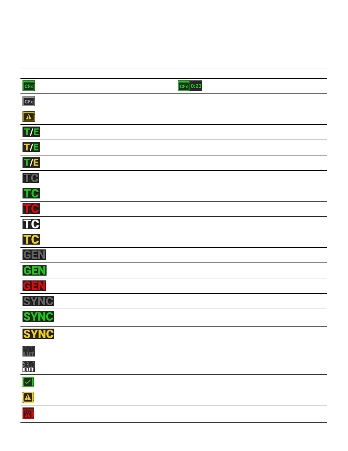
STATUS ICONS
The following is a table of the camera's status icons.
ICON DESCRIPTION
The CFexpress Type B media card is good ( and recording time remaining)
The media card is missing
The media card is incompatible
The sensor temperature (T) and exposure (E) calibration are good
The sensor temperature (T) requires calibration
The sensor exposure (E) requires calibration
Gray indicates that no Timecode generator signal is detected
Green indicates that the Timecode source is connected and jammed
Red indicates that the Timecode source is connected and not jammed
White indicates that the Timecode source is jammed and not connected
Yellow indicates that the Timecode source is cross-jammed (at a different Project Time Base)
Gray indicates that no Genlock signal is detected
Green indicates that the camera is receiving and is locked to a Genlock signal
Red indicates that the camera is receiving and is not locked to a Genlock signal
Gray indicates that no synchronization is detected
Green indicates that the camera's sensor is synchronized with Timecode and that the camera's output
is synchronized with a Genlock signal
Yellow indicates that the camera's sensor is NOT synchronized with Timecode and that the camera's
output is synchronized with a single camera or a Genlock signal
Gray indicates that no 3D LUTs are in use
White indicates that the camera is using a 3D LUT
Camera temperature is good
Camera overheating warning
Camera overheating
COPYRIGHT © 2023 RED.COM, LLC 955-0218, REV A | 242
KOMODO-X
®
OPERATION GUIDE
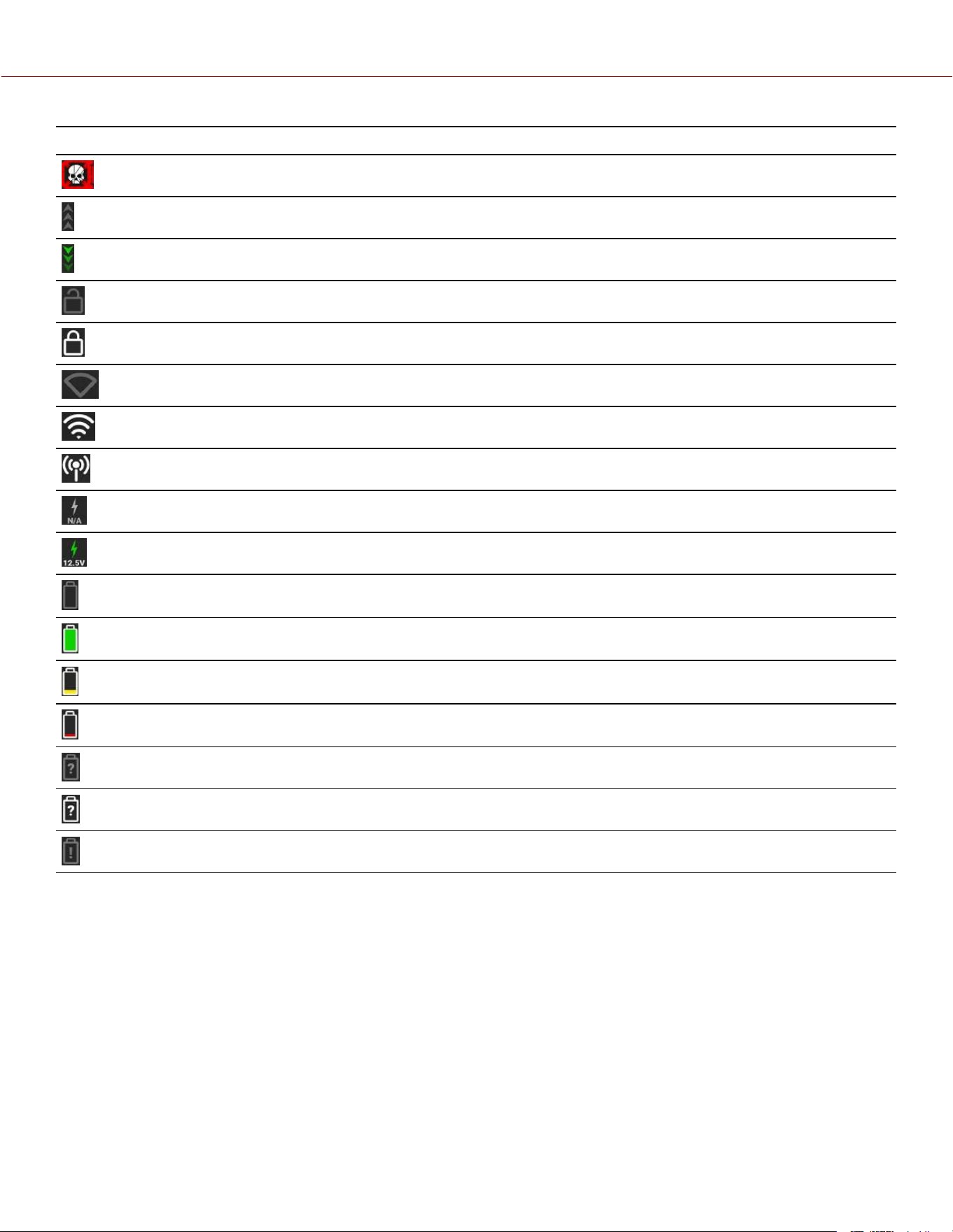
ICON DESCRIPTION
Camera shutting down
Gray indicates no FTPS data is transferring
Green arrows indicate FTPS data is transferring
Gray and open indicates that the camera LCD is unlocked
White and closed indicates that the camera LCD is locked
Gray and empty indicates that no Wi-Fi signal is detected
White bars indicate the strength of the Wi-Fi signal detected (Infrastructure)
White antenna indicates that Wi-Fi signal is broadcasting (Ad-hoc)
Gray indicates that no DC power is connected
Green indicates that the camera is receiving DC power
Gray indicates that no battery is connected
White indicates that the battery is connected and green shows the relative level of charge remaining
Yellow indicates 10 minutes of power remaining
Red indicates less than 5 minutes of power remaining
Gray question mark indicates no communication with the battery and no power
White question mark indicates no communication with the battery and power
Gray exclamation point indicates error communicating with the battery and no power
COPYRIGHT © 2023 RED.COM, LLC 955-0218, REV A | 243
KOMODO-X
®
OPERATION GUIDE
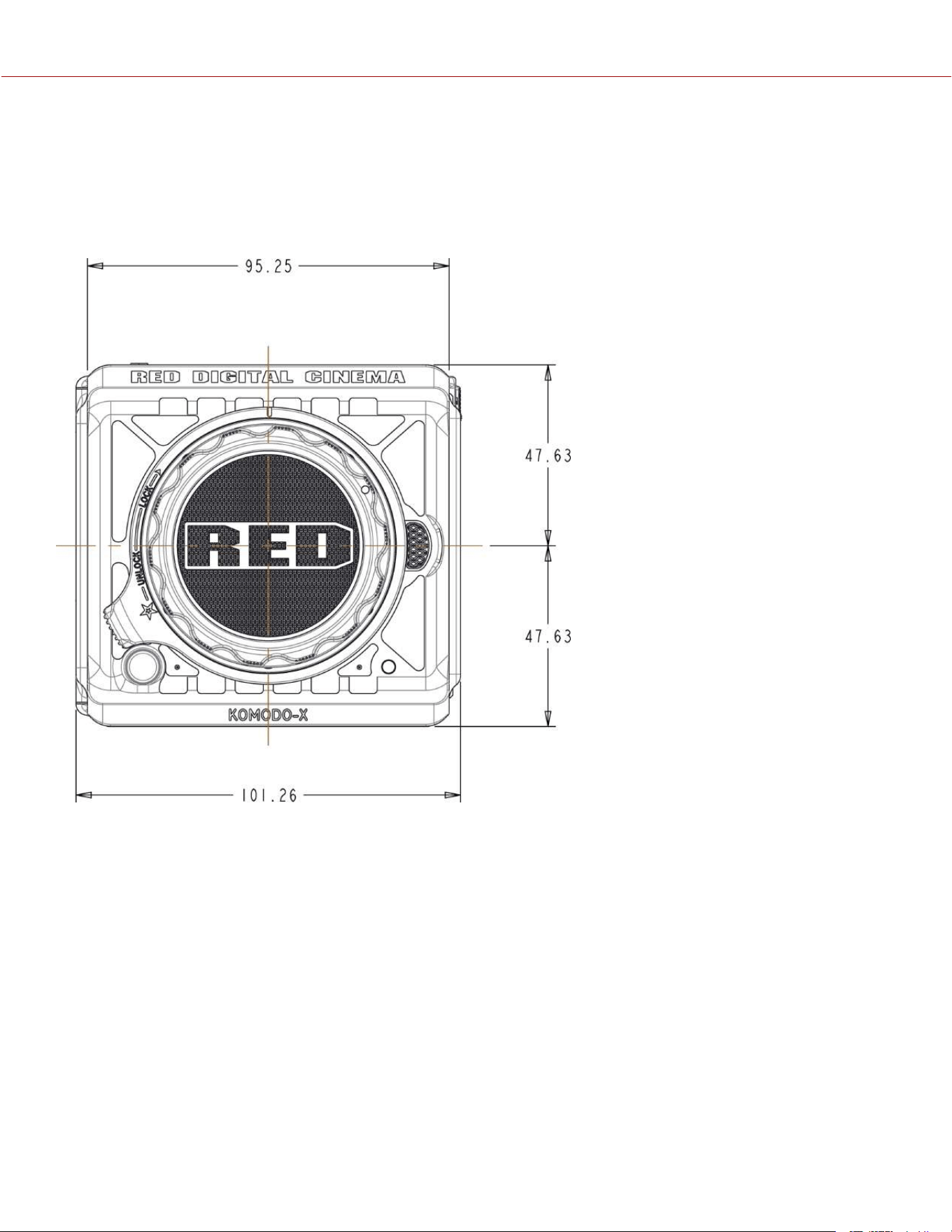
COPYRIGHT © 2023 RED.COM, LLC 955-0218, REV A | 244
A. MECHANICAL DRAWINGS
NOTE: Dimensions are shown in mm.
FRONT VIEW
Figure: Camera Front View
KOMODO-X
®
OPERATION GUIDE
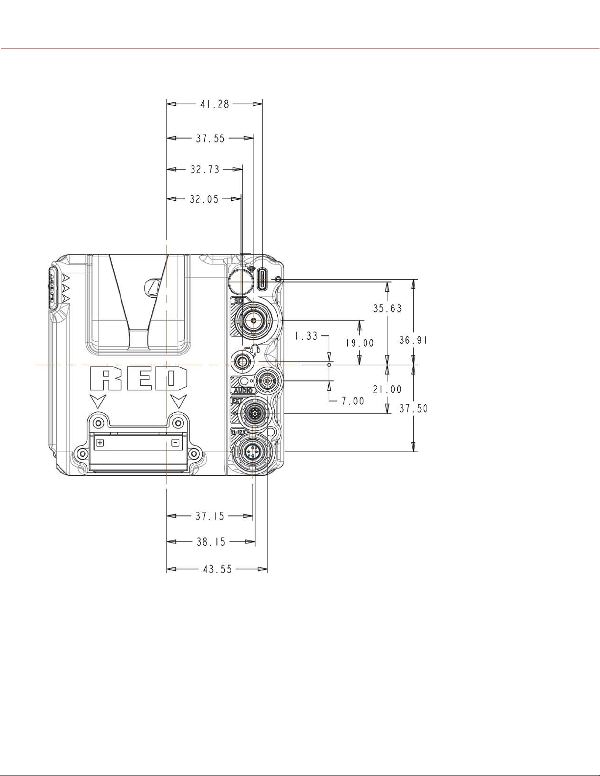
BACK VIEW
Figure: Camera Back View
COPYRIGHT © 2023 RED.COM, LLC 955-0218, REV A | 245
KOMODO-X
®
OPERATION GUIDE
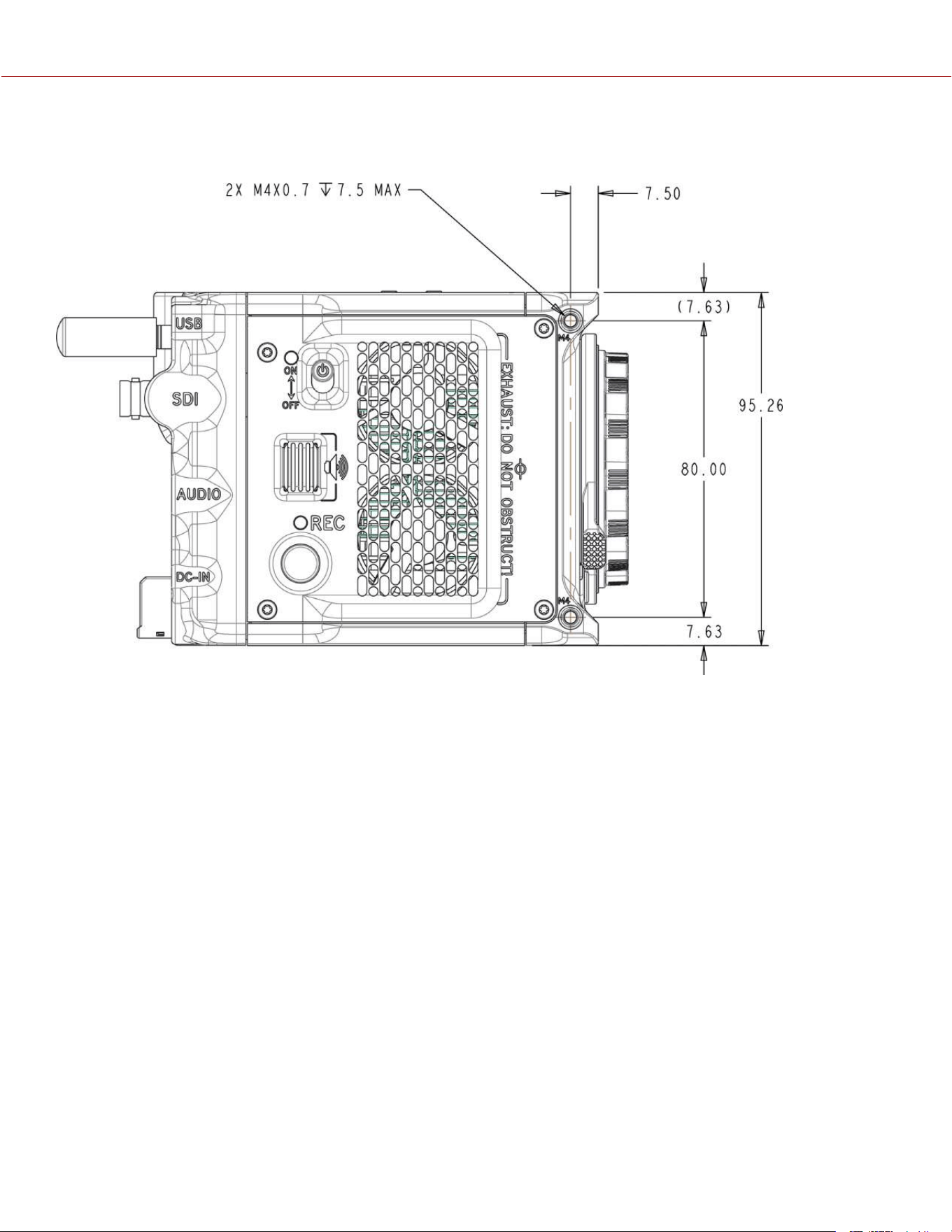
RIGHT SIDE VIEW
Figure: Camera Side View (Right)
COPYRIGHT © 2023 RED.COM, LLC 955-0218, REV A | 246
KOMODO-X
®
OPERATION GUIDE
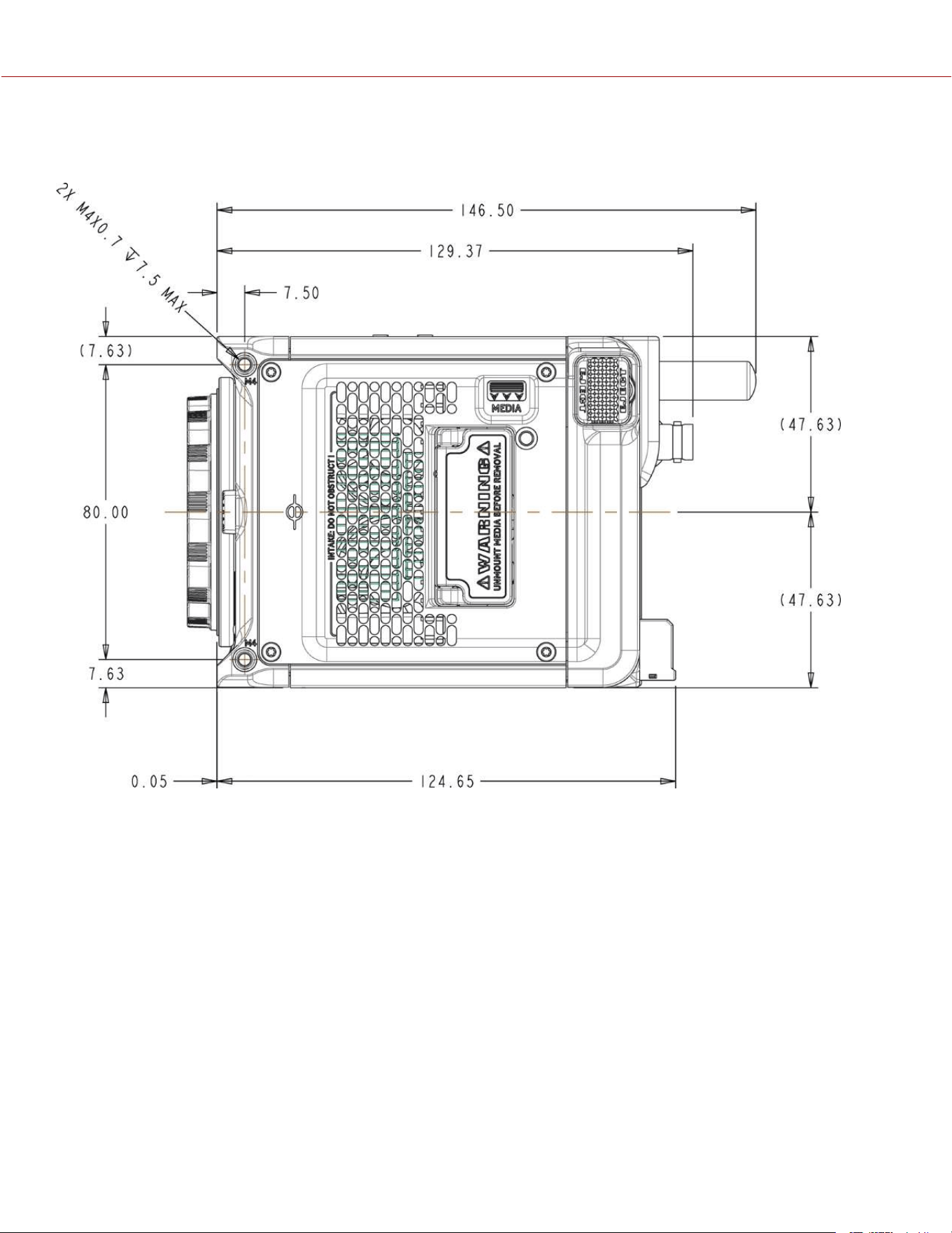
LEFT SIDE VIEW
Figure: Camera Side View (Left)
COPYRIGHT © 2023 RED.COM, LLC 955-0218, REV A | 247
KOMODO-X
®
OPERATION GUIDE

TOP VIEW
Figure: Camera Top View
COPYRIGHT © 2023 RED.COM, LLC 955-0218, REV A | 248
KOMODO-X
®
OPERATION GUIDE
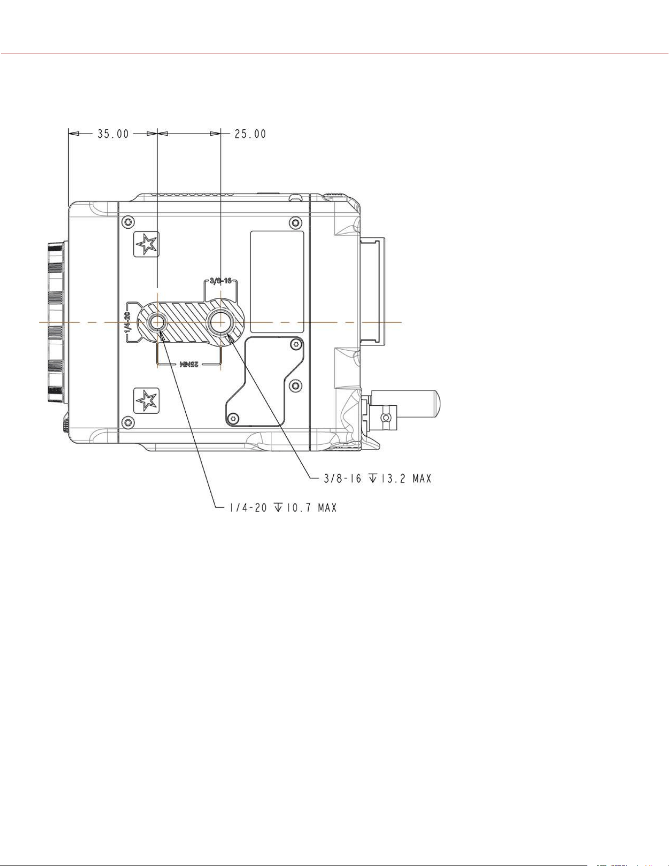
BOTTOM VIEW
Figure: Camera Bottom View
COPYRIGHT © 2023 RED.COM, LLC 955-0218, REV A | 249
KOMODO-X
®
OPERATION GUIDE
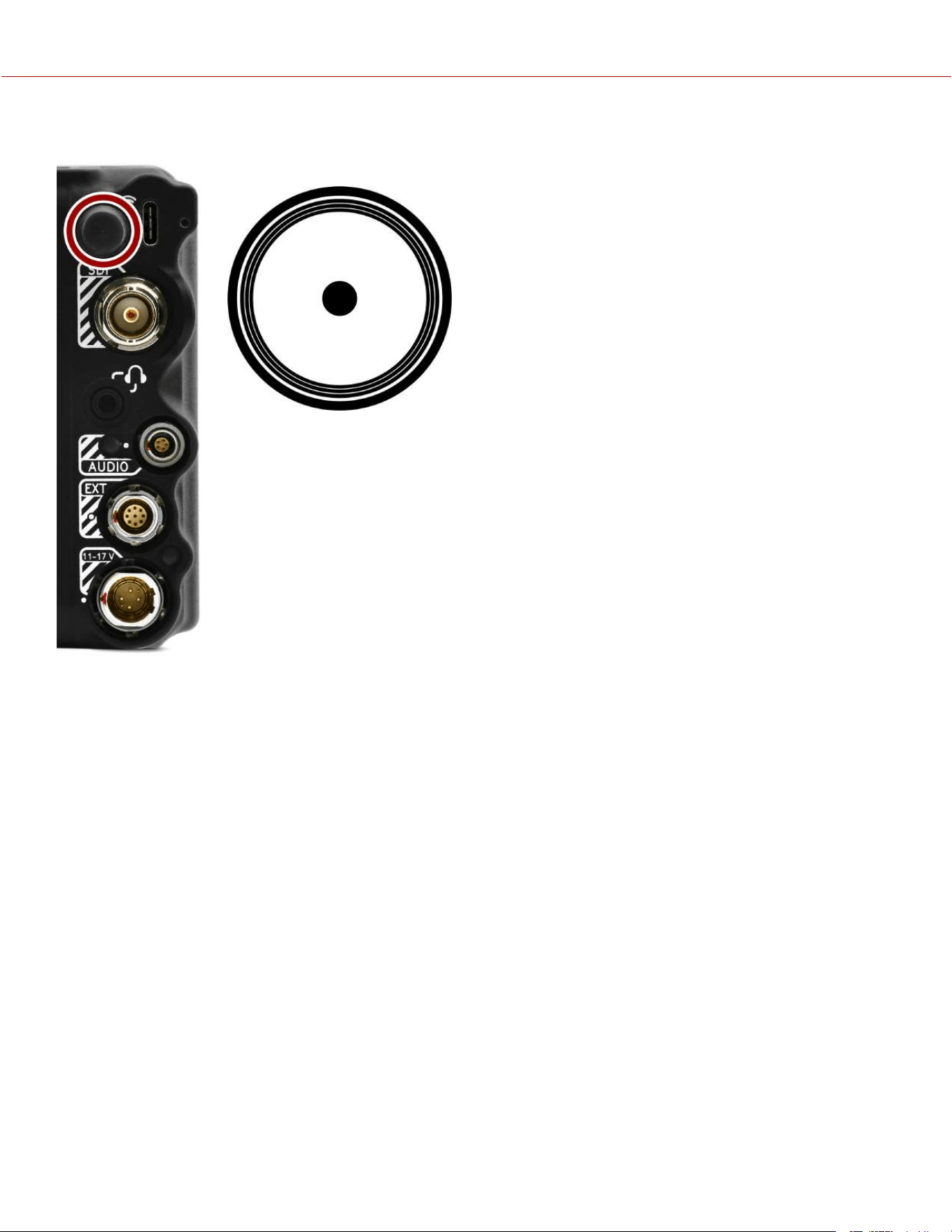
FEMALE RP SMA PORT
The female RP SMA connector provides an attachment for the male RP SMA Wi-Fi antenna.
Figure: Front face of the female RP SMA port (looking at the back of the camera).
NOTE: Mating connector is a Wi-Fi antenna with a standard male RP SMA connector.
COPYRIGHT © 2023 RED.COM, LLC 955-0218, REV A | 250
KOMODO-X
®
OPERATION GUIDE
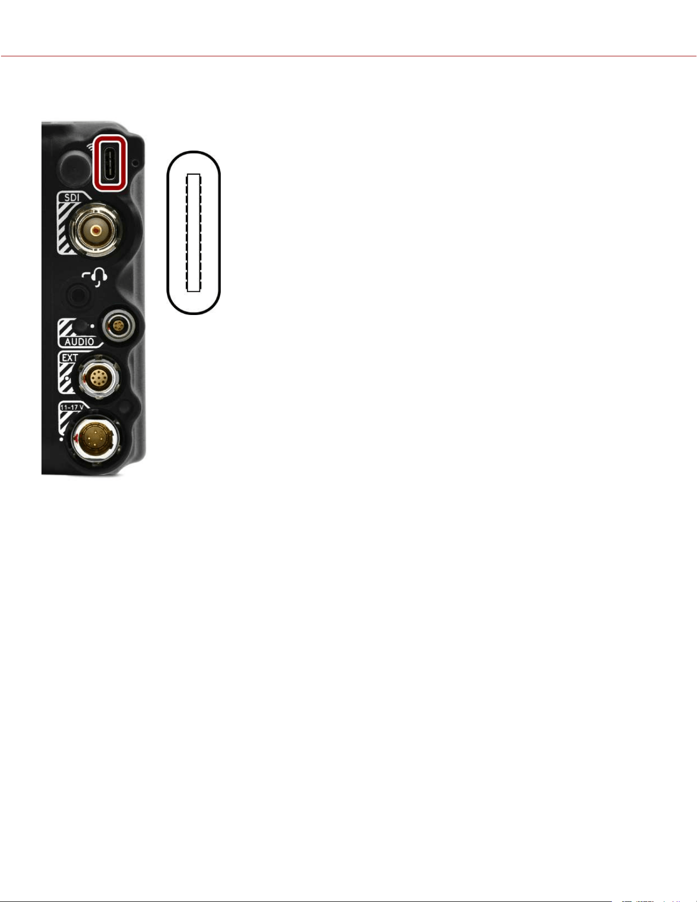
USB TYPE-C PORT
The USB Type-C port is used primarily for data connections. The USB Type-C port provides 5
volts at 0.5 amps.
Figure: Front face of the USB-C port (looking at the back of the camera).
NOTE: Mating connector is a standard USB-C male connector.
COPYRIGHT © 2023 RED.COM, LLC 955-0218, REV A | 251
KOMODO-X
®
OPERATION GUIDE
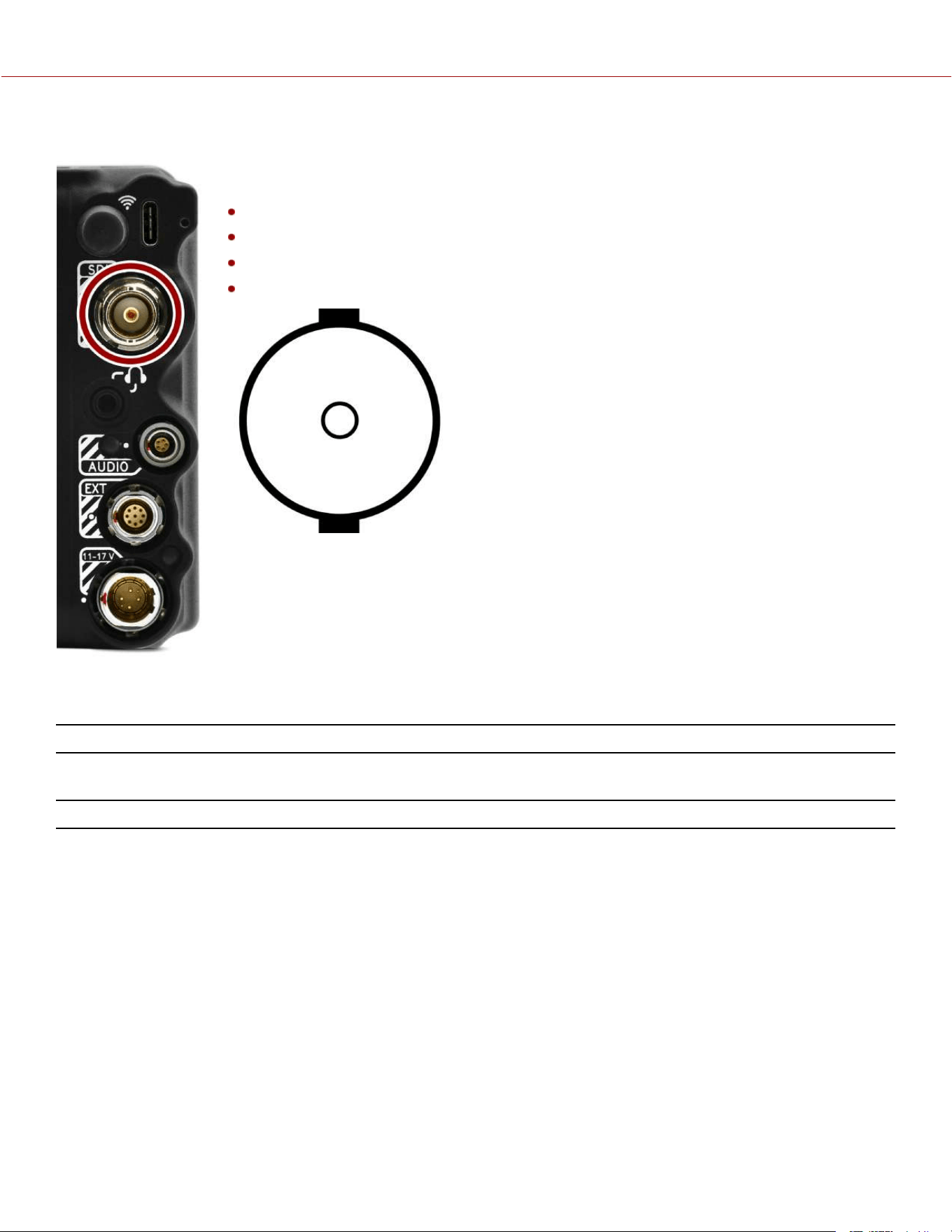
12G-SDI
The 12G-SDI male 75-ohm BNC port deliver 12, 6, 3, or 1.5 Gbps of image bandwidth ideal for
the 4Kp60 format. Other features include:
Up to Four (4) channels of embedded audio
Time of Day and Edge Timecode
Record Tally flag
Clip name information (as SMPTE RP-188 VITC2 HANC metadata)
Figure: Front face of the 12G-SDI male BNC connector (looking at the back of the camera).
12G-SDI 75-OHM MALE BNC CONNECTOR
PIN SIGNAL DESCRIPTION DIRECTION
Center 12/6/3/1.5 G-SDI
Signal
Up to 4096 x 2160: 422 for 60p - Log view or LUT view (SMPTE ST
2082)
Out
Shell Ground Common ground (camera ground) N/A
NOTE: Mating connector is standard 75-ohm female BNC connector rated for 12G-SDI.
WARNING: Under certain circumstances, it is possible for an SDI connector to incur damage when connected to an
accessory and powered without using shielded cables. RED recommends only using high quality, shielded BNC cables
that are rated for 12G-SDI signals and only using shielded power cables for powering SDI accessories.
Make sure power is connected to the SDI accessory at all times before you connect the BNC to the camera.
Ungrounded power from SDI accessories can damage the camera’s SDI port. To avoid this possible damage, attach the
power source to the accessory before attaching it to the BNC cable. When using RED Approved Third Party battery
plates, unplug the BNC cable prior to hot swapping.
When possible, avoid using P-Tap (also known as D-Tap) cables to power accessories. To avoid damage when using P-
Tap/D-Tap, it’s imperative that the connect/disconnect sequence (below) is followed precisely.
COPYRIGHT © 2023 RED.COM, LLC 955-0218, REV A | 252
KOMODO-X
®
OPERATION GUIDE

BNC ATTACHMENT INSTRUCTIONS
When attaching SDI accessories:
1. Connect a power source to the SDI accessory; power on the SDI accessory.
2. Ensure a power source is connected to the camera. This ensures both are grounded prior to connecting the BNC.
The camera's power state does not have an impact on SDI attachment sequence.
3. Connect the BNC cable to the accessory, then to the camera.
When detaching an accessory mounted to an SDI output, ensure that you remove the BNC connection to the camera
before removing power to the SDI device:
1. Shutdown the SDI accessory.
2. Disconnect the BNC cable from the camera.
3. Disconnect the power source from the SDI accessory.
When you need to swap out a battery on an accessory mounted to the camera’s SDI port, you must:
1. Shutdown the SDI accessory.
2. Disconnect the BNC cable from the camera.
3. Replace the battery on the SDI accessory.
4. Connect the BNC cable to the camera.
5. Power on the SDI accessory.
For more information, refer to Preventing Damage to SDI Outputs.
COPYRIGHT © 2023 RED.COM, LLC 955-0218, REV A | 253
KOMODO-X
®
OPERATION GUIDE
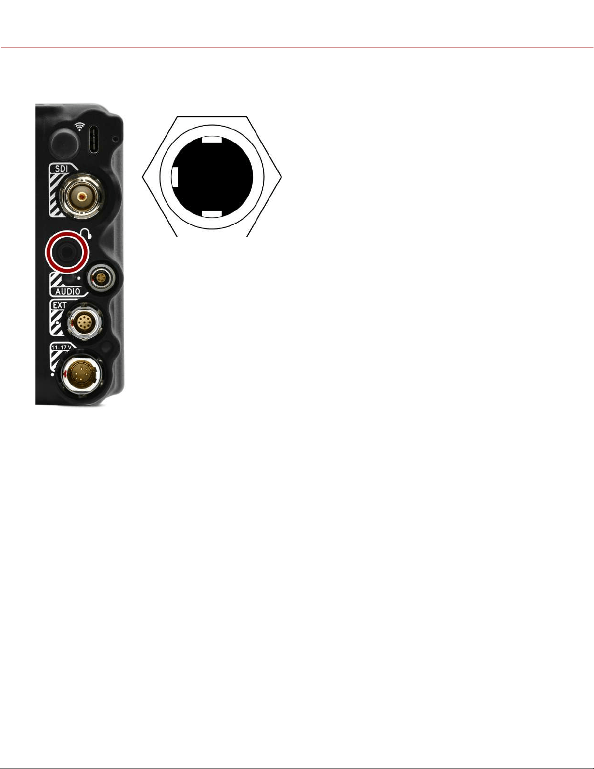
HEADPHONE JACK
The female stereo 3.5 mm headphone port provides an attachment for stereo headphones.
NOTE: Only use headphones with a 3-conductor jack. If you try to use a headset with a mic
and 4-conductor jack, it will produce unpredictable results.
Figure: Front face of the female 3.5 mm headphone port (looking at the back of the camera).
NOTE: Mating connector is a 3.5 mm stereo headphone plug.
COPYRIGHT © 2023 RED.COM, LLC 955-0218, REV A | 254
KOMODO-X
®
OPERATION GUIDE

AUDIO PORT
The female LEMO 5-Pin 00B audio connector accepts 2-channel audio, Line, Mic, and +48V
Phantom Power.
Figure: Front face of the female 5-Pin 00B audio connector (looking at the back of the camera).
LEMO 5-PIN 00B FEMALE AUDIO CONNECTOR
PIN
SIGNAL DESCRIPTION
1
Ground Ground to camera
2
Ch 3 + Channel 3 signal (positive)
3
Ch 3 - Channel 3 negative
4
Ch 4 + Channel 4 signal (positive)
5
Ch 4 - Channel 4 negative
NOTE: Mating connectors are FGG.00.305.CLAD35Z (5-Pin 00 circular push-pull connector, straight plug) and
FHG.00.305.CLAD35Z (5-Pin 00 circular push-pull connector, right-angle plug).
Accessories:
DSMC3™ RED® 5-Pin to Single 3.5 mm Adapter
DSMC3™ RED® 5-Pin to Dual XLR Adapter
COPYRIGHT © 2023 RED.COM, LLC 955-0218, REV A | 255
KOMODO-X
®
OPERATION GUIDE
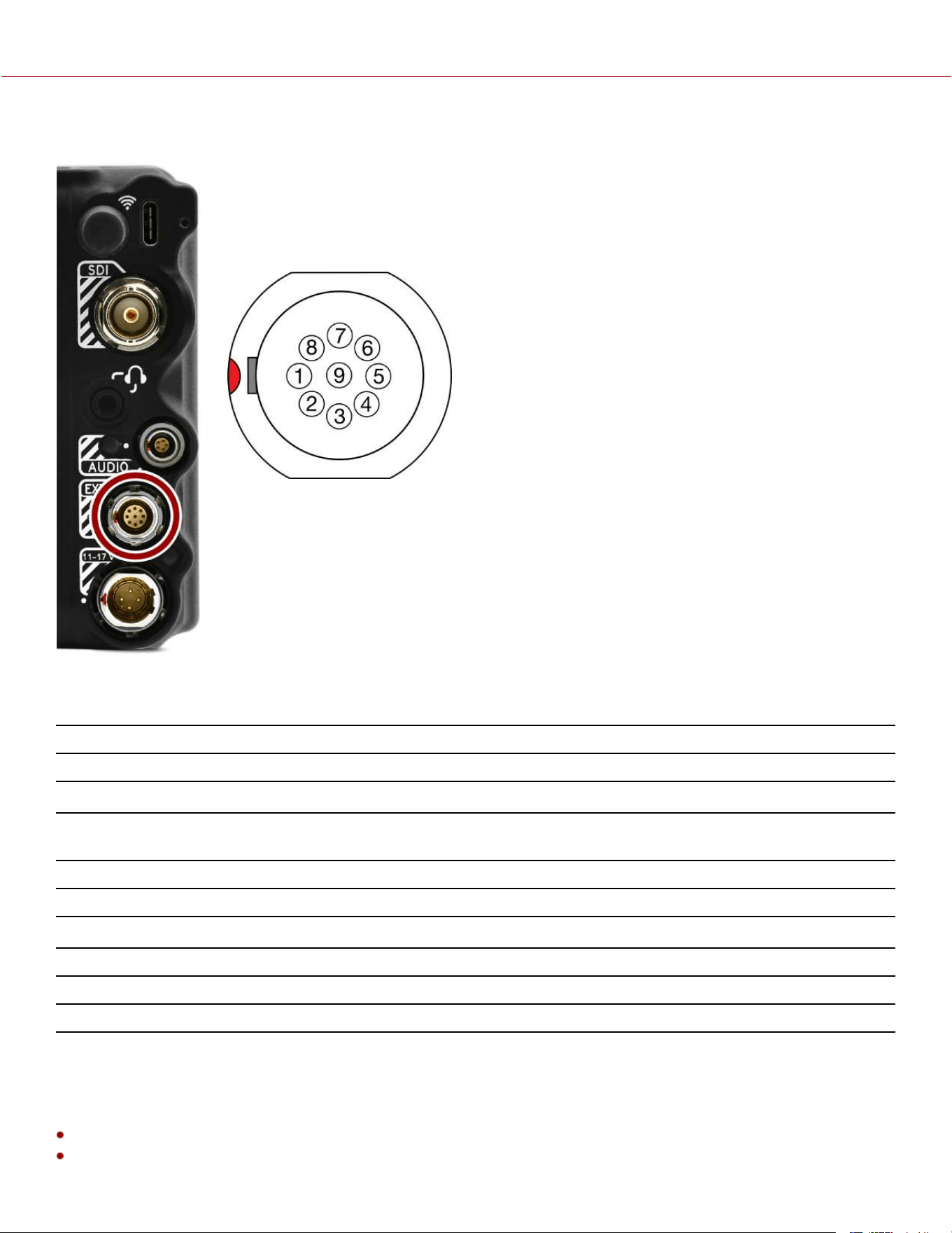
EXTENSION PORT
The female 9-contact 0B ODU Extension port supports serial (RS-232 RX and TX), a General
Purpose Input (GPI) trigger (active-low switch closure), General Purpose Output (GPO),
Timecode, and Genlock. The connector also offers auxiliary 5-Volt power out, with a maximum
sustained current draw of 500 mA.
To operate the GPI contact closure style trigger, short Pin 6 (GPI) to Pin 9 (ground).
Figure: Front face of the female 9-contact Extension port (looking at the back of the camera).
NOTE: The required mating connector is 9-Pin 0L Straight Plug Connector (ODU, part#
SX0L0X-P09MCC0-0001).
9-PIN 0B ODU EXTENSION PORT PINOUT
PIN
SIGNAL DETAILS
1
5 V AUX 5 Volt AUX (500 mA Max) enabled using the Power menu
2
Timecode Out Timecode Out – SMPTE 12M
1
3
GPO General Purpose Out: Recording Indicator Out, Sensor Sync Out using 3.3 volt
logic level
4
UART TX Serial RS-232 transmit (refer to the Serial menu)
5
UART RX Serial RS-232 receive (refer to the Serial menu)
6
GPI General Purpose In, 3.3-Volt logic level
2
7
Timecode In Timecode In – SMPTE 12M
8
Genlock Tri-Level Genlock In (SMPTE 296M and 274M)
9
GND Signal and power ground
1. Not currently supported.
2. The signal path includes a resistor pulling the signal high, which is designed to work with a closure switch connected to GND.
COMPATIBLE CABLES
790-0685: RED 9-Pin EXT to Flying Lead 1.3’
790-0674: RED EXT to Timecode 3'
COPYRIGHT © 2023 RED.COM, LLC 955-0218, REV A | 256
KOMODO-X
®
OPERATION GUIDE
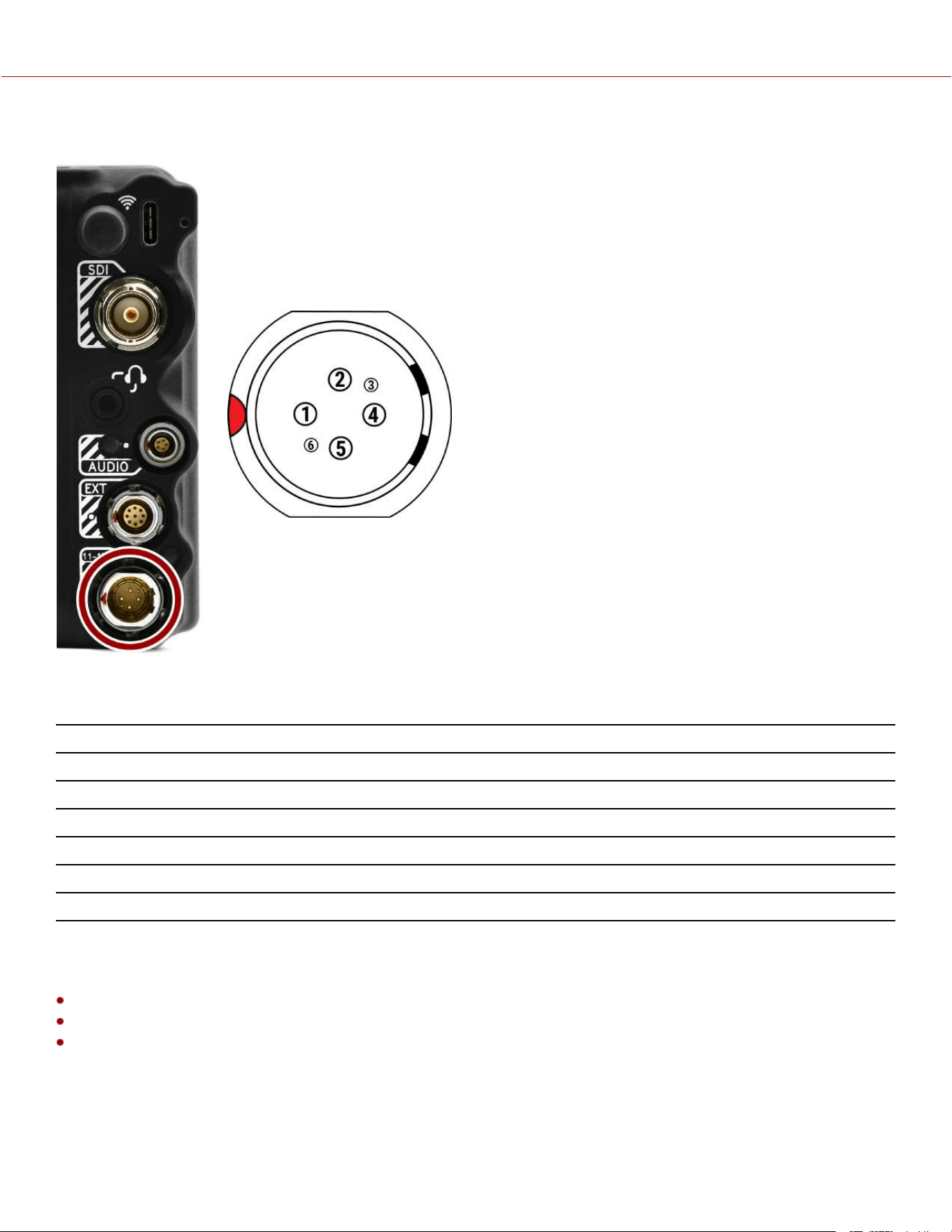
6-PIN DC-IN
The male 6-Pin 1B DC-IN connector accepts DC input power from 11 V DC to 17 V DC. A
built-in power conditioner protects against reverse-polarity connections, electrostatic
discharge (ESD), undervoltage, overvoltage, and overcurrent.
WARNING: Both pairs of +VBATT and GROUND pins must be wired. Using a third-party
power cable that wires only one (1) pair of +VBATT and GROUND pins may damage the power
supply or the camera. Damage to the power supply or other components of the camera
system caused by using an inappropriate power cable is not covered under warranty.
Figure: Front face of the male 6-Pin 1B DC power input connector (looking at the back of the
camera).
6-PIN 1B DC INPUT CONNECTOR
PIN
SIGNAL DESCRIPTION
1
+VBATT Power input, +11.5 to +17 V DC
2
+VBATT Power input, +11.5 to +17 V DC
3
SCL-BATT Battery SMBus SCL signal (3.3 V)
4
GROUND Power return (camera ground)
5
GROUND Power return (camera ground)
6
SDA-BATT Battery SMBus SDA signal (3.3 V)
NOTE: Mating connector is FGJ.1B.306.CWLD72Z.
COMPATIBLE CABLES
790-0638: DSMC AC Power Adaptor Pack
790-0164: XLR Power Cable (10')
790-0291: DSMC Battery Belt Clip
COPYRIGHT © 2023 RED.COM, LLC 955-0218, REV A | 257
KOMODO-X
®
OPERATION GUIDE
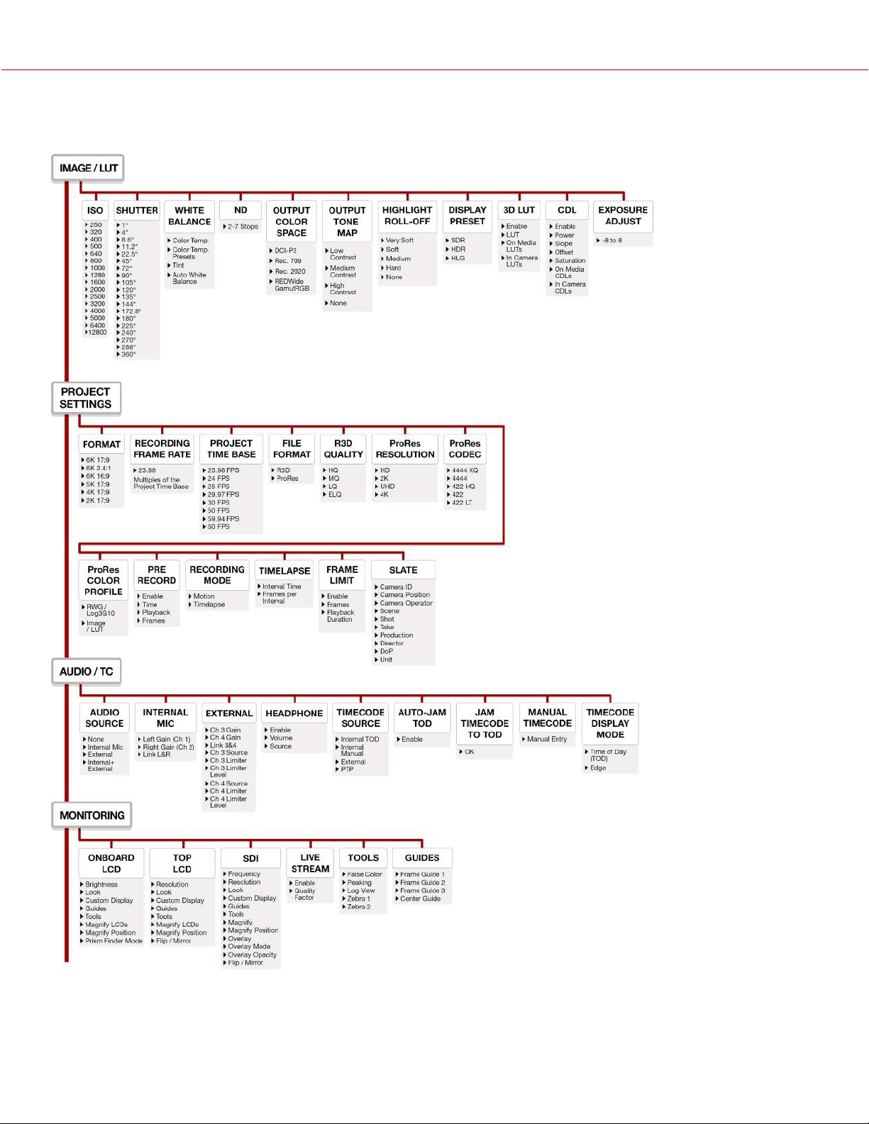
COPYRIGHT © 2023 RED.COM, LLC 955-0218, REV A | 258
B. MENU MAP
KOMODO-X
®
OPERATION GUIDE
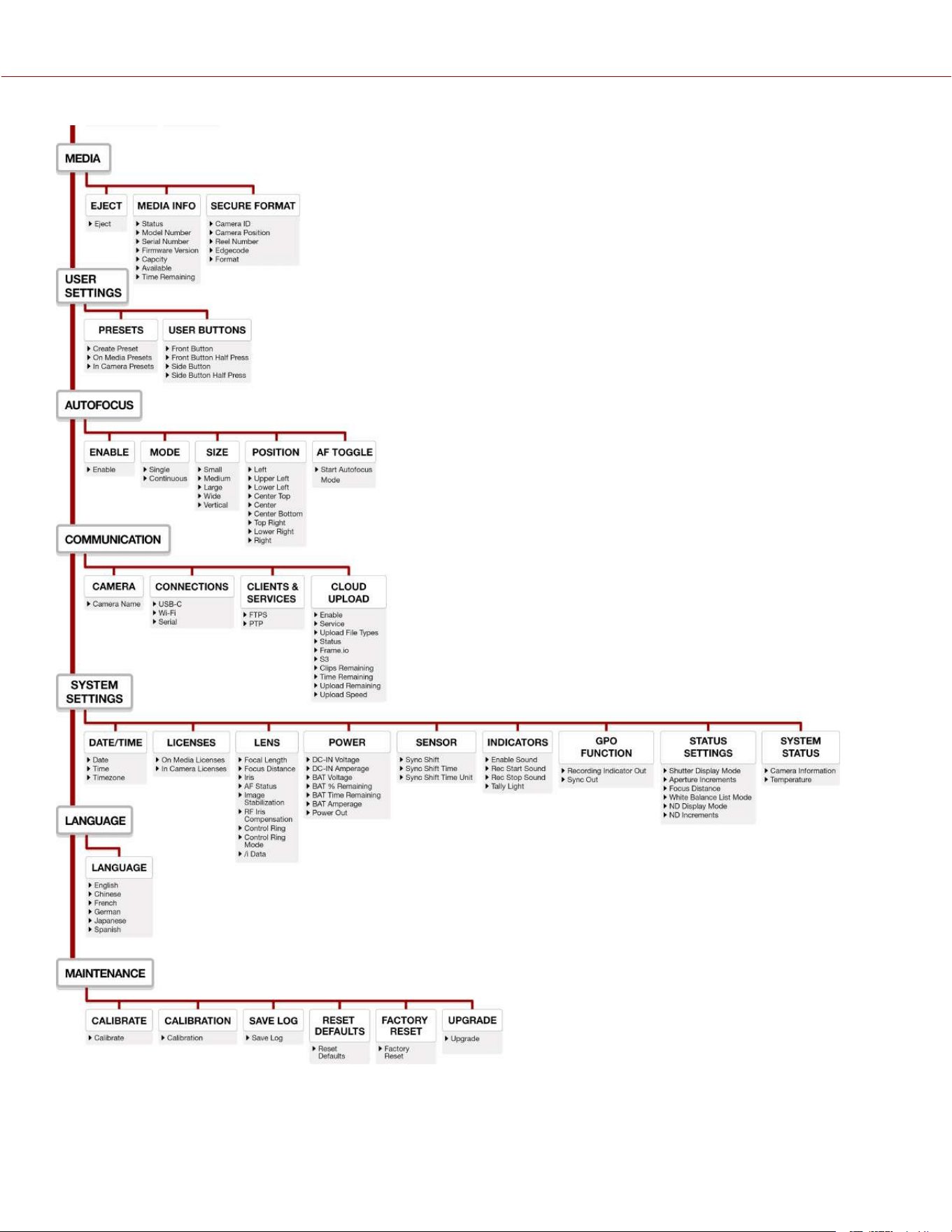
COPYRIGHT © 2023 RED.COM, LLC 955-0218, REV A | 259
KOMODO-X
®
OPERATION GUIDE
COPYRIGHT © 2023 RED.COM, LLC 955-0218, REV A | 260
C. TECHNICAL SPECIFICATIONS
Technical specifications reflect both current and projected information. Everything is subject to change.
RED KOMODO-X™ CAMERA
SPECIFICATION DESCRIPTION
Sensor Type KOMODO-X™ 19.9 MP Super 35 mm Global Shutter CMOS
Effective Pixels 6144 x 3240
Sensor Size 27.03 mm x 14.26 mm (Diagonal: 30.56 mm)
Dynamic Range 16.5+ stops
Mount Type Integrated locking RF mount with electronic communication
Supports /i PL lenses with RED RF to PL Adapters
Supports Canon EF adapter with communication and other adapters based on the RF mount
Max Data Rates Up to 560 MB/s using RED branded or other qualified CFexpress media cards
1
REDCODE
®
RAW
Maximum Frame Rates
80 fps at 6K 17:9 (6144 x 3240)
96 fps at 5K 17:9 (5120 x 2700)
120 fps at 4K 17:9 (4096 x 2160)
240 fps at 2K 17:9 (2048 x 1080)
Playback Frame Rates
(Project Time Base)
23.98, 24, 25, 29.97, 30, 50, 59.94, 60 fps, all resolutions
Best Available REDCODE
®
Settings
REDCODE HQ, MQ, LQ, and ELQ at 6K 17:9 (6144 x 3240) up to 80 fps
REDCODE HQ, MQ, LQ, and ELQ at 4K 17:9 (4096 x 2160) up to 120 fps
REDCODE HQ, MQ, LQ, and ELQ at 2K 17:9 (2048 x 1080) up to 240 fps
REDCODE
®
RAW Acquisition
Formats
6K 17:9 (6144 x 3240), 2:1, 2.4:1, 16:9. 1:1, and Anamorphic 2x, 1.8x, 1.6x, 1.5x, 1.3x, 1.25x
5K 17:9 (5120 x 2700) and 16:9
4K 17:9 (4096 x 2160) and 16:9
2K 17:9 (2048 x 1080)
Apple
®
ProRes Dedicated recording in 4K (4096 x 2160) ProRes 4444 XQ up to 60 fps, ProRes 4444 up to 80 fps,
and ProRes 422 HQ, ProRes 422, and ProRes 422 LT up to 120 fps
Construction Aluminum Alloy
Dimensions L x W x H = 5.1 in x 4 in x 3.8 in (129.37 mm x 101.26 mm x 95.26 mm) largest fixed dimensions
Weight 2.62 lb (without body cap and CFexpress card)
Media Type CFexpress Type B
Battery Type Integrated V-Lock battery interface optimized for Micro V-Lock Batteries
1
DC Power 11v-17v through a 6-pin DC-IN
Operating Temperature 0°C to 40°C (32°F to 104°F)
Storage Temperature –20°C to 50°C (–4°F to 122°F)
Relative Humidity 0% to 85% non-condensing
Color Management Image Processing Pipeline 2 (IPP2)
Supports 33×33×33 3D LUTs
Supports import and adjustment of CDLs
KOMODO-X
®
OPERATION GUIDE

RED KOMODO-X™ CAMERA
SPECIFICATION DESCRIPTION
Audio Integrated dual channel digital mono microphones, uncompressed, 24-bit 48 kHz
Integrated dual channel (mic/line/+48V) input through a 5-Pin 00B Audio Port, uncompressed, 24-
bit 48 kHz
3.5 mm stereo headphone port
Autofocus
Phase Detect and Contrast
Monitor Options Proprietary Top Accessory Port for Monitoring and Control
Integrated 2.9" 1440 x 1440 touchscreen LCD with preview and camera control
Integrated 12G-SDI with 6G-SDI, 3G-SDI and 1.5G-SDI modes
12G-SDI: Up to 4096 x 2160 4:2:2 for 60p
6G-SDI: Up to 4096 x 2160 4:2:2 for 30p
3G-SDI: Up to 2048 x 1080 4:2:2 for 60p
1.5G-SDI: Up to 2048 x 1080 4:2:2 for 30p, 24p
SMPTE Timecode, HANC Metadata, 24-bit 48 kHz Audio
Additional I/O Tri-Level Genlock Input through the 9-Pin EXT port
LTC Timecode Input through the 9-Pin EXT port
RS232 CTRL (using RCP2) through the 9-Pin EXT port
IP Connected Wi-Fi (2.4 GHz / 5 GHz) for camera control, video preview, and media offloading
Ethernet over USB Type-C for camera control, video preview, and media offloading
MJPEG 1080p live stream accessible through Wi-Fi and USB-C
PTP for frame level synchronization
R3D live broadcasting available with RED Connect license and 5Gbps Ethernet adapter
SOFTWARE
RED Control App
RED Control Pro App
Access full camera controls and live preview from iOS or Android devices
Pro App: Operate one or multiple cameras over an IP connection to synchronize settings, manage
media files locally or upload directly to FrameIO, develop custom looks with advanced CDL and
LUT controls, and more
Ideal for control of multi-camera arrays, multi-cam shoots, and live events, all from one central
location
Standard app available from the Apple App Store and Google Play Store
RED Control Pro available via Apple App store only and requires additional purchase
RED Control works wirelessly or wired over USB-C
1. For more information on approved mount adaptors, lenses, batteries, accessories and media cards, refer to RED Third-Party Accessories
COPYRIGHT © 2023 RED.COM, LLC 955-0218, REV A | 261
KOMODO-X
®
OPERATION GUIDE
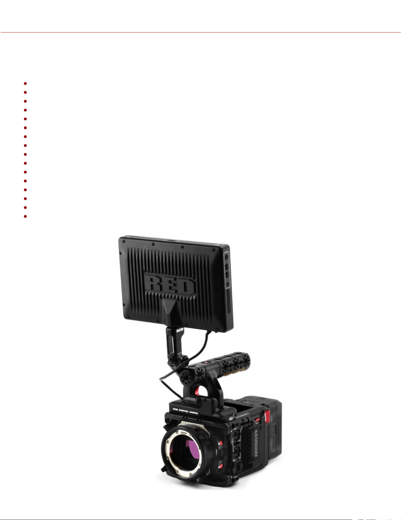
COPYRIGHT © 2023 RED.COM, LLC 955-0218, REV A | 262
D. ACCESSORIES
The following is a list of camera accessories. Some are optional, depending on the package you purchase:
REDVOLT® NANO-V Battery
REDVOLT® MICRO-V Battery
RED® Compact Dual V-Lock Charger
CFexpress Type B Media
KOMODO-X™ RF to PL Adapter Pack
KOMODO-X™ RF to PL with Electronic ND Adapter Pack
DSMC3™ RED® Touch 7.0" LCD
DSMC3™ RED® Touch 7.0" LCD Hood
KOMODO-X™ Power Adaptor
Outrigger Handle
KOMODO® Wing Grip
RED® Compact Top Handle and Extensions
DSMC3™ RED® 5-Pin to Single 3.5 mm Adapter
DSMC3™ RED® 5-Pin to Dual XLR Adapter
RED® Pro I/O Module
RED Control Apps
KOMODO-X
®
OPERATION GUIDE
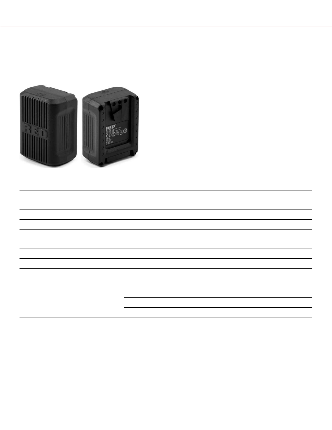
REDVOLT
®
NANO-V BATTERY
The REDVOLT NANO-V battery is a small, lightweight power solution for the KOMODO-X. Weighing in at only 0.63 lb
(288 g), it is ideal for gimbals, drones, and other setups where form factor and weight matter. The battery's dimensions
(66 mm x 88 mm x 44 mm) ensure the camera retains completely flat surfaces on the top and sides, allowing users to
attach various combinations of cages and plates, without issue.
Featuring a 49 Wh capacity and with a maximum output current of 6 amps, the battery can power the KOMODO-X and
DSMC3™ RED® Touch 7.0” LCD for short durations when you want to shoot in as light a configuration as possible.
ITEM DETAILS
Type Rechargeable Lithium-Ion Battery
Capacity 3300 mAh / 49 Wh
Battery output 12 to 16.8 V DC
Maximum load 6 Amps at 14 V DC
Operating temperature 50° F ~ 113° F (10° C ~ 45° C)
Charging temperature 32° F ~ 104° F (0° C ~ 40° C)
Storage temperature 68° F ~ 122° F (20° C ~ 50° C)
Charger RED Compact Dual V-Lock charger
Weight Approximately 0.63 lb (288 g)
Dimensions Height: 3.46 in. (88 mm)
Width: 2.60 in. (66 mm)
Depth: 1.30 in. (44 mm)
REDVOLT NANO-V was designed in partnership with Core SWX and is compatible with most cameras/modules that
accept V-Lock batteries. For issues or troubleshooting, please visit https://coreswx.supportsystem.com.
COPYRIGHT © 2023 RED.COM, LLC 955-0218, REV A | 263
KOMODO-X
®
OPERATION GUIDE
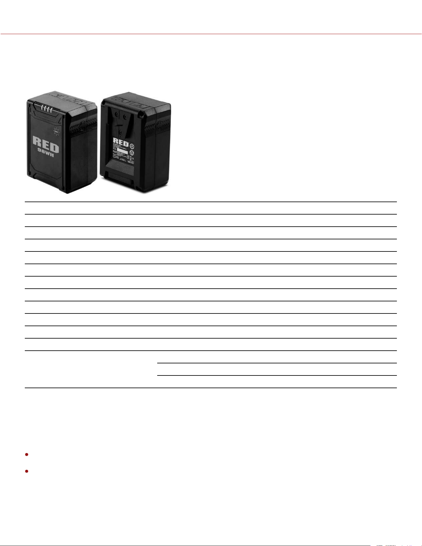
REDVOLT
®
MICRO-V BATTERY
The REDVOLT MICRO-V 14.7 Volt V-Lock battery includes an LED charge level indicator, a P-tap port, and a USB
power port.
ITEM DETAILS
Type Rechargeable Lithium-Ion Battery
Capacity 6600 mAh / 98 Wh
Battery output 14.8 V DC
P-tap output 12 V DC
USB output 5 V DC (3 Amps)
Maximum load 12 Amps at 14 V DC
Operating temperature 50° F ~ 113° F (10° C ~ 45° C)
Charging temperature 32° F ~ 104° F (0° C ~ 40° C)
Storage temperature 68° F ~ 122° F (20° C ~ 50° C)
Charger RED Compact Dual V-Lock charger
Weight Approximately 1.2 lb (544.3 g)
Dimensions Height: 3.93 in. (99.8 mm)
Width: 2.82 in. (71.6 mm)
Depth: 1.94 in. (49.3 mm)
COMPATIBLE BATTERIES
Compatible batteries are those that provide enough current (14.4 V with 6 A or greater) to power the RED KOMODO-X,
and that also fit the dimensions on the KOMODO-X's integrated Micro V-Lock plate.
RED chose the Micro V-Lock for the KOMODO-X to keep its form-factor compact. As a result, not all V-Lock batteries
are compatible with the camera.
NOTE:
V-Lock batteries with a width greater than 2.95 in. (75 mm) are not compatible with the camera’s Micro V-Lock plate
and will require the battery adapter.
The camera can charge a battery that supports SMBus communication directly. To charge the battery, the camera
must be powered off while connected to DC-IN power. You can also use the optional RED Compact Dual V-Lock
charger.
COPYRIGHT © 2023 RED.COM, LLC 955-0218, REV A | 264
KOMODO-X
®
OPERATION GUIDE
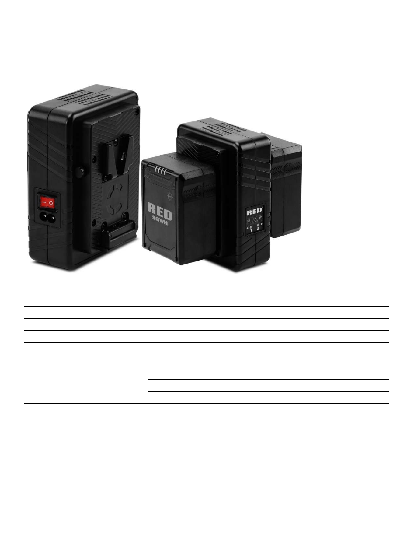
RED
®
COMPACT DUAL V-LOCK CHARGER
The optional RED Compact Dual V-Lock charger allows you to charge two REDVOLT batteries.
ITEM DETAILS
Input 100 V - 240 V AC 50 Hz to 60 Hz
Charge current One battery 3 Amps, two batteries 1.5 Amps
Charging temperature 32° F ~ 104° F (0° C ~ 40° C)
Storage temperature 68° F ~ 122° F (20° C ~ 50° C)
Battery compatibility REDVOLT MICRO-V 14.7 V DC
Weight Approximately 1 lb (453.5 g)
Dimensions Height: 4.5 in. (114.3 mm)
Width: 5.5 in. (139.7 mm)
Depth: 3 in. (76.2 mm)
COPYRIGHT © 2023 RED.COM, LLC 955-0218, REV A | 265
KOMODO-X
®
OPERATION GUIDE
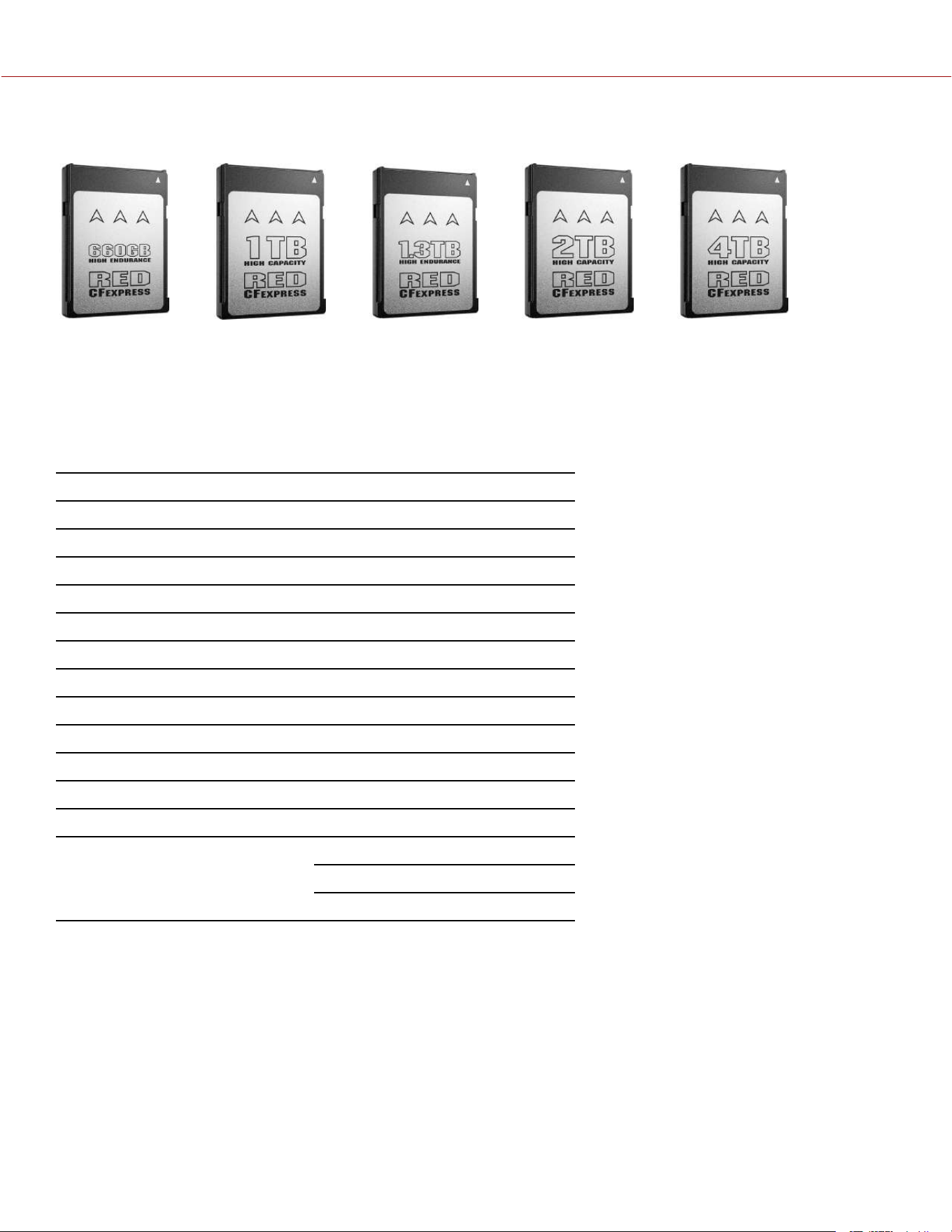
CFEXPRESS TYPE B MEDIA
The RED CFexpress Type B Media provides the camera with 660 gigabyte, 1, 1.3, 2, and 4 terabyte recording options.
The 2 TB and 660 GB cards use the same hardware as do the 1.3 TB and 4 TB. The differences come from the software
and firmware, which configure the media differently to prioritize different feature sets. The 1 TB, 2 TB and 4 TB prioritize
capacity while still providing excellent durability under normal use. The 660 GB and 1.3 TB are in an overprovisioned
configuration of the same media to prioritize extended write cycles and improved thermal performance for constant
writing and re-writing of data. The underlying hardware is identical.
ITEM DETAILS
Type CFexpress Type B Media
Capacity - 660 GB High Endurance 660,138,909,696 bytes
Capacity - 1 TB High Capacity 1,099,511,627,776 bytes
Capacity - 1.3 TB High Endurance 1,331,512,536,141 bytes
Capacity - 2 TB High Capacity 2,048,480,824,832 bytes
Capacity - 4 TB High Capacity 4,096,961,649,664 bytes
Operating temperature 14° F to 158° F (-10° C to 70° C)
Operating humidity 5% to 95%, non-condensing
Storage temperature -4° F to 185° F (-20° C to 85° C)
Shock resistance (operating) 50 g
Vibration resistance (operating) 15 g at 10 Hz to 2000 Hz
Weight Approximately 0.25 oz (7.1 g)
Dimensions Height: 1.52 in. (38.5 mm)
Width: 1.17 in. (29.6 mm)
Depth: 0.15 in. (3.8 mm)
COPYRIGHT © 2023 RED.COM, LLC 955-0218, REV A | 266
KOMODO-X
®
OPERATION GUIDE
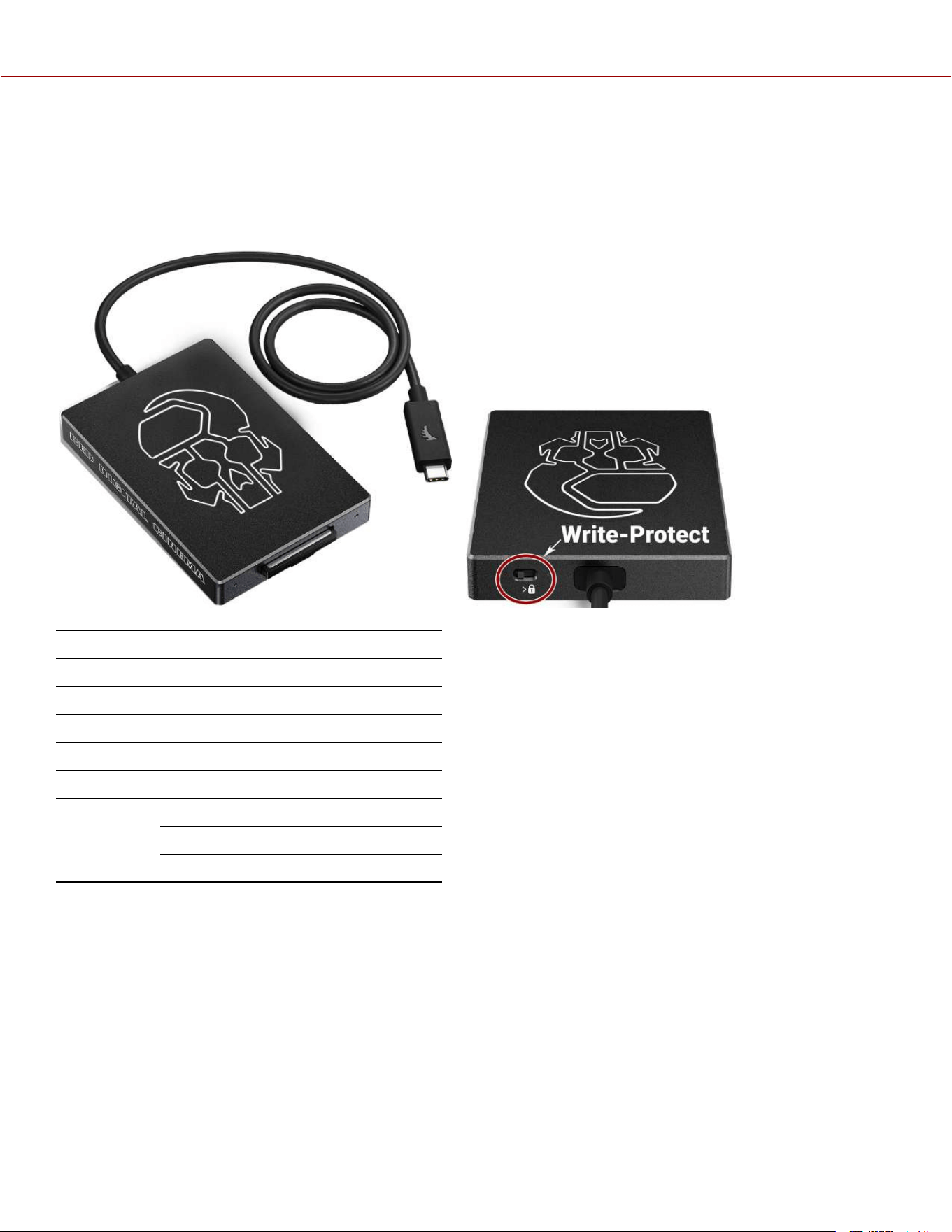
RED
®
CFEXPRESS TYPE B READER
The RED CFexpress Type B Card Reader provides a fast USB-C connection with the capability of write-protect.
Set the Write-Protect switch to the Lock position to prevent connected devices from adding any unwanted data to your
CFexpress Type B card.
ITEM DETAILS
Media read CFexpress Type B
Interface USB-C 3.2 cable to CFexpress Type B
Power USB bus power
Cable USB-C 3.2 cable type A to C adapter
Weight Approximately 4.2 oz (120 g)
Dimensions Height: 3.74 in. (95 mm)
Width: 2.56 in. (65 mm)
Depth: 0.47 in. (12 mm)
COPYRIGHT © 2023 RED.COM, LLC 955-0218, REV A | 267
KOMODO-X
®
OPERATION GUIDE
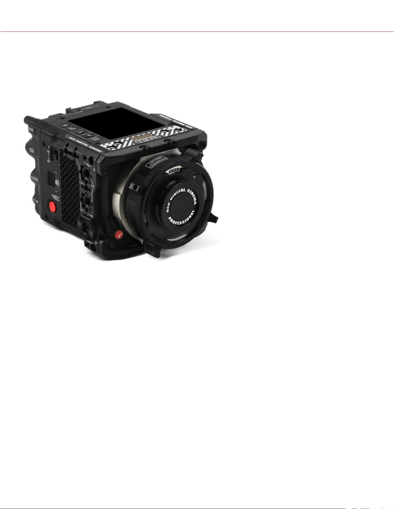
KOMODO-X™ RF TO PL ADAPTER PACK
The RED
®
KOMODO-X RF to PL Adapter Pack provides a robust PL mount solution for the RED KOMODO-X.
Supporting Cooke /i lens communication, power and record triggering, the RF to PL Adapter expands the functionality
of the camera's native RF lens mount for professional applications. Constructed of a titanium core, the shimmable RF to
PL Adapter is resistant to environmental temperature changes, providing consistent and precise back focus.
The RED KOMODO-X RF to PL Adapter Pack includes both the KOMODO-X Side Ribs and Adapter Support Brackets
to provide additional rigidity and a native-like mount experience.
NOTE: KOMODO-X RF to PL adapter is not compatible with Electronic Filters.
COPYRIGHT © 2023 RED.COM, LLC 955-0218, REV A | 268
KOMODO-X
®
OPERATION GUIDE
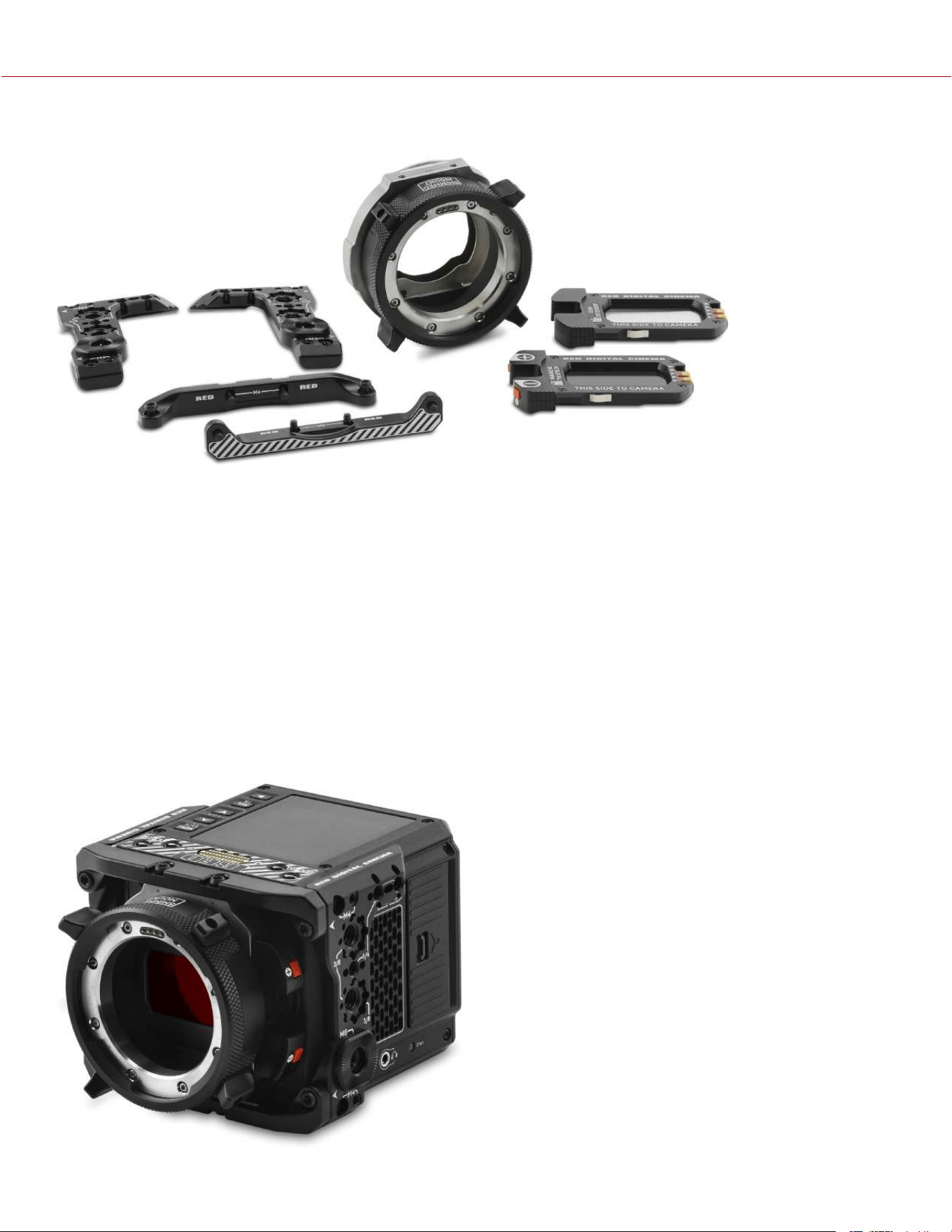
KOMODO-X™ RF TO PL WITH ELECTRONIC ND ADAPTER PACK
The RED
®
KOMODO-X RF to PL with Electronic ND Adapter Pack includes two filters; A clear filter for when no ND is
needed and an Electronic ND Filter with a 2-7 stop range. It features precise control of ¼, 1/3 or full stop increments
which allows choosing the exact exposure without compromising the intended aperture.
Each clear and electronic ND filters thickness are measured and paired together to ensure no back focus shifts when
switching between filters. ND can be controlled via the integrated buttons on the Electronic ND Filter, onboard LCD,
DSMC3™ RED
®
Touch 7.0” LCD, RED Control, RED Control Pro, web interface, or any other RCP2 compatible remote
control, allowing for easy access to exposure no matter how the camera is configured.
Supporting Cooke /i lens communication and record triggering, the RF to PL Adapter w/ Electronic ND expands the
functionality of the camera's native RF lens mount for professional applications. Constructed of a titanium core, the
shimmable RF to PL Adapter is resistant to environmental temperature changes, providing consistent and precise back
focus.
The RED KOMODO RF to PL Adapter w/ Electronic ND Filter Adapter Pack includes both the KOMODO
®
Side Ribs and
Adapter Support Brackets to provide additional rigidity and a native-like mount experience.
COMPATIBILITY: Only compatible with KOMODO and KOMODO-X.
COPYRIGHT © 2023 RED.COM, LLC 955-0218, REV A | 269
KOMODO-X
®
OPERATION GUIDE
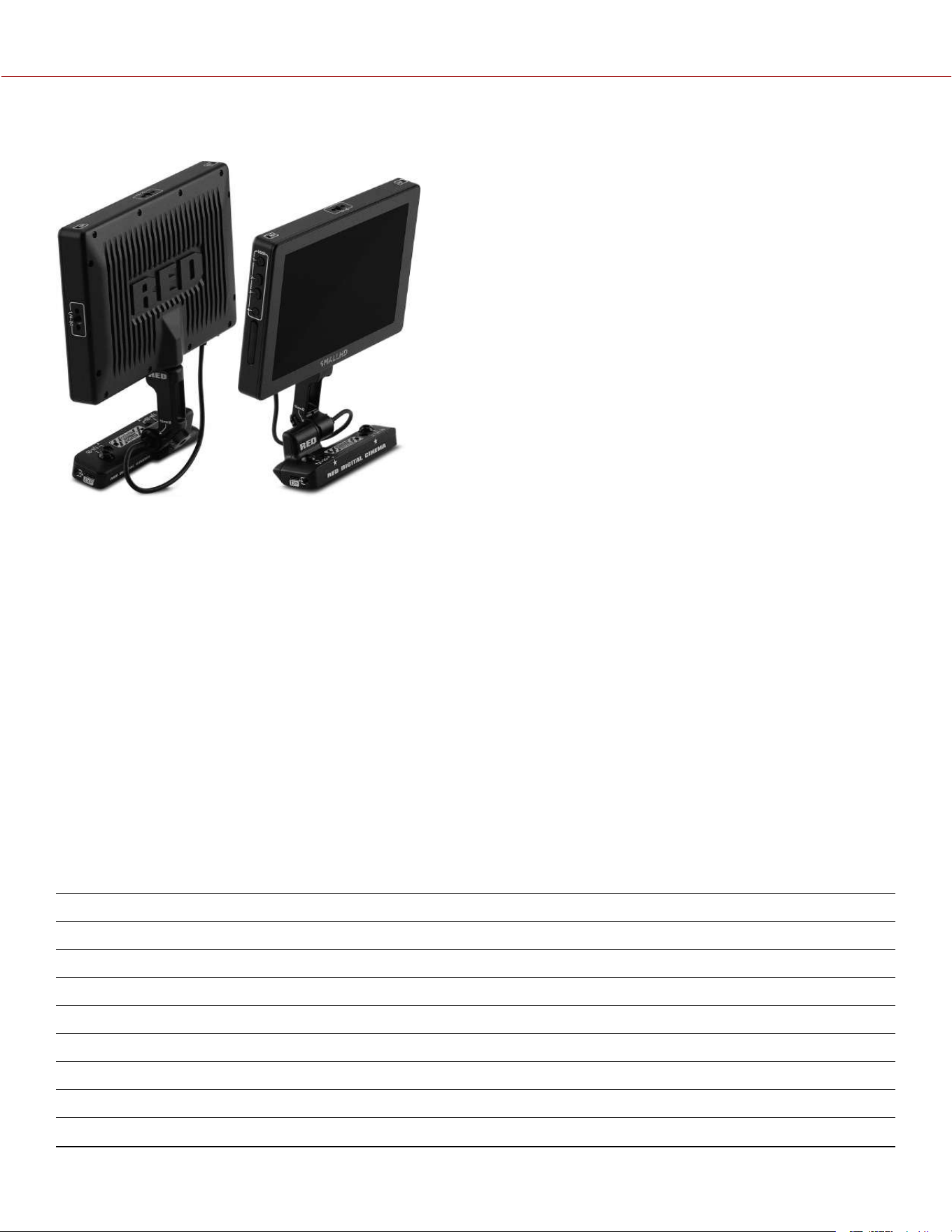
DSMC3™ RED
®
TOUCH 7.0" LCD
The optional DSMC3™ RED Touch 7.0" LCD offers an HD viewing experience for recording and viewing footage on the
V-RAPTOR™ XL camera. A 1920 x 1200 resolution display panel with peak brightness of 1300 nits and high pixel
density (at 322 ppi), not only provides the optimal experience when viewing footage, but also features 100% DCI-P3
color gamut coverage for tremendous color accuracy.
This monitor also features full control over the camera through the new responsive menu system powered by SmallHD
PageOS. The features include Waveform, Vectorscope, Histogram, False Color, Color Picker, Pixel Zoom, and more.
The lightweight display mounts to a removable integrated tilt arm with the capability to rotate 180 degrees for versatile
mounting options.
It also boasts the latest generation pogo pins to provide power and video to the monitor, and the ability to connect
through a single-locking USB-C-style DSMC3™ RMI cable for video and power. No additional SDI or power cables are
needed.
Refer to RED Monitor Interface Cable for more information.
NOTE: The USB-C-style DSMC3™ RMI cable is not a standard USB-C cable. The DSMC3™ RED Touch 7.0" LCD is
not compatible with DSMC
®
, DSMC2
®
, RED RANGER
®
or KOMODO
®
camera systems.
For more information, refer to the DSMC3™ RED
®
Touch 7.0" LCD User Guide.
SPECIFICATIONS
ITEM DETAILS
Material Aluminum alloy
Resolution 1920 x 1200
Pixel density 322 ppi
Refresh rate 60 Hz
Response time 25 ms
Contrast 1250:1
Brightness 1300 cd/m2
Color depth 10-bit (8-bit panel)
COPYRIGHT © 2023 RED.COM, LLC 955-0218, REV A | 270
KOMODO-X
®
OPERATION GUIDE
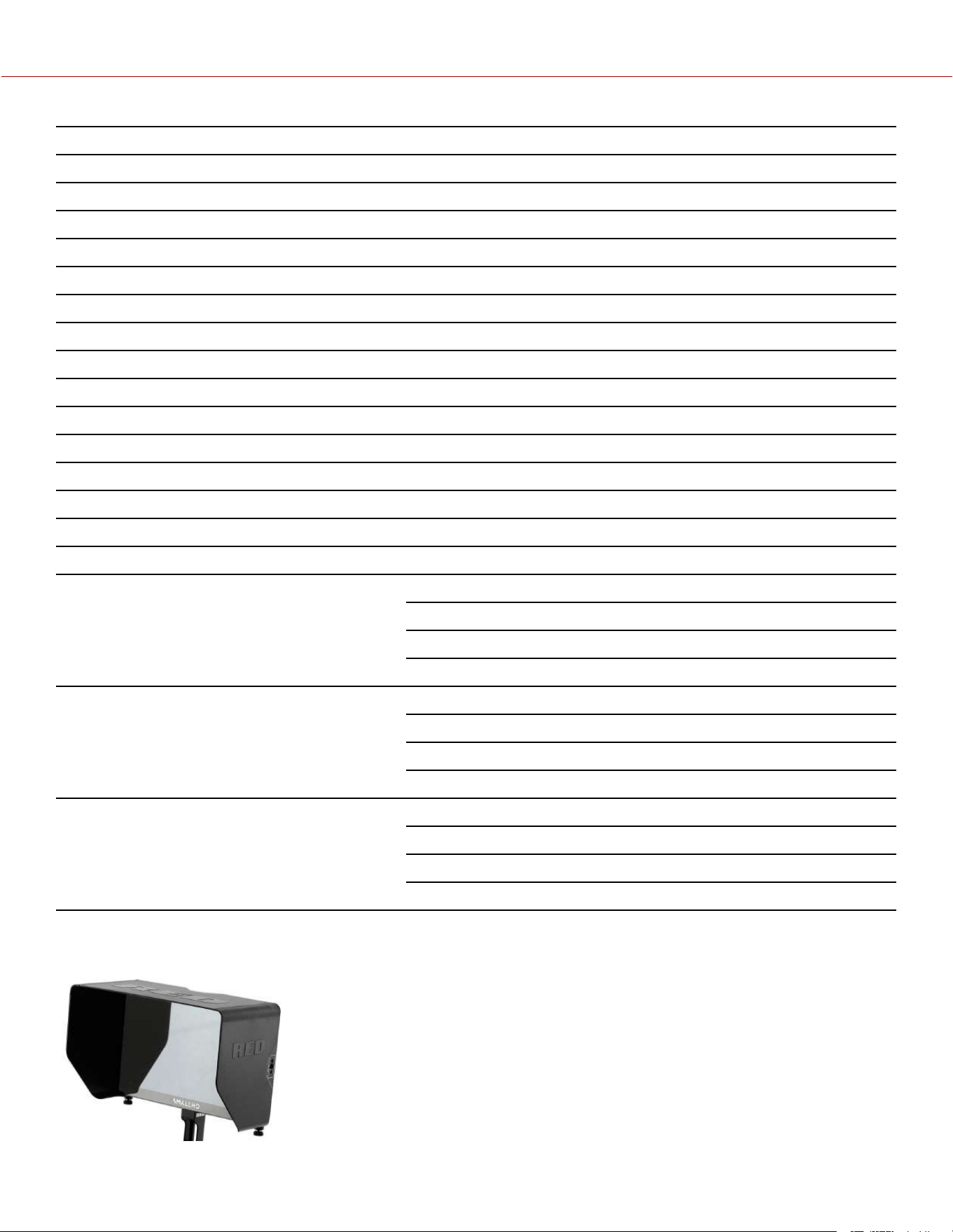
ITEM DETAILS
Colors 100% DCI-P3
Viewing angle ± 160° all axes
Display orientation Landscape, 180° rotation
Touch pCap Multi-Touch
Camera connection Power and communication through the RMI cable
Mounting 15 mm rail
Hood Mounting 4 x M3 mounting points
Buttons 4 buttons function 1, 2, 3 & 4
EXP Ports For future use, not currently supported
Power consumption 15.5 Watts
Operating temperature 32° F to 104° F (0° C to 38° C)
Storage temperature –0° F to 120° F (–18° C to 49° C)
Operating humidity 0% to 85%, non-condensing
Storage humidity 0% to 85%, non-condensing
Firmware requirement Compatible with V-RAPTOR firmware version 1.1 or later
Monitor dimensions Weight approximately 1.25 lb (568.0 g)
Height: 4.67 in. (118.70 mm)
Width: 7.09 in. (180.10 mm)
Depth: 1.13 in. (28.80 mm)
Arm dimensions Weight approximately 0.07 lb (30.1 g)
Height: 1.18 in. (30.00 mm)
Width: 2.40 in. (61.00 mm)
Depth: 0.70 in. (17.50 mm)
RED Monitor Interface (RMI) dimensions Weight approximately 0.28 lb (126 g)
Height: 1.67 in. (42.50 mm)
Width: 4.25 in. (108.00 mm)
Depth: 1.51 in. (38.23 mm)
DSMC3™ RED
®
TOUCH 7.0" LCD HOOD
The DSMC3™ RED® Touch 7.0” LCD Hood attaches easily and directly to the
DSMC3™ RED® Touch 7.0” LCD and can block out the sun to make viewing the
LCD easier in bright conditions.
COMPATIBILITY: The DSMC3™ RED® Touch 7.0” LCD Hood is only compatible with
the DSMC3™ RED® Touch 7.0” LCD.
COPYRIGHT © 2023 RED.COM, LLC 955-0218, REV A | 271
KOMODO-X
®
OPERATION GUIDE
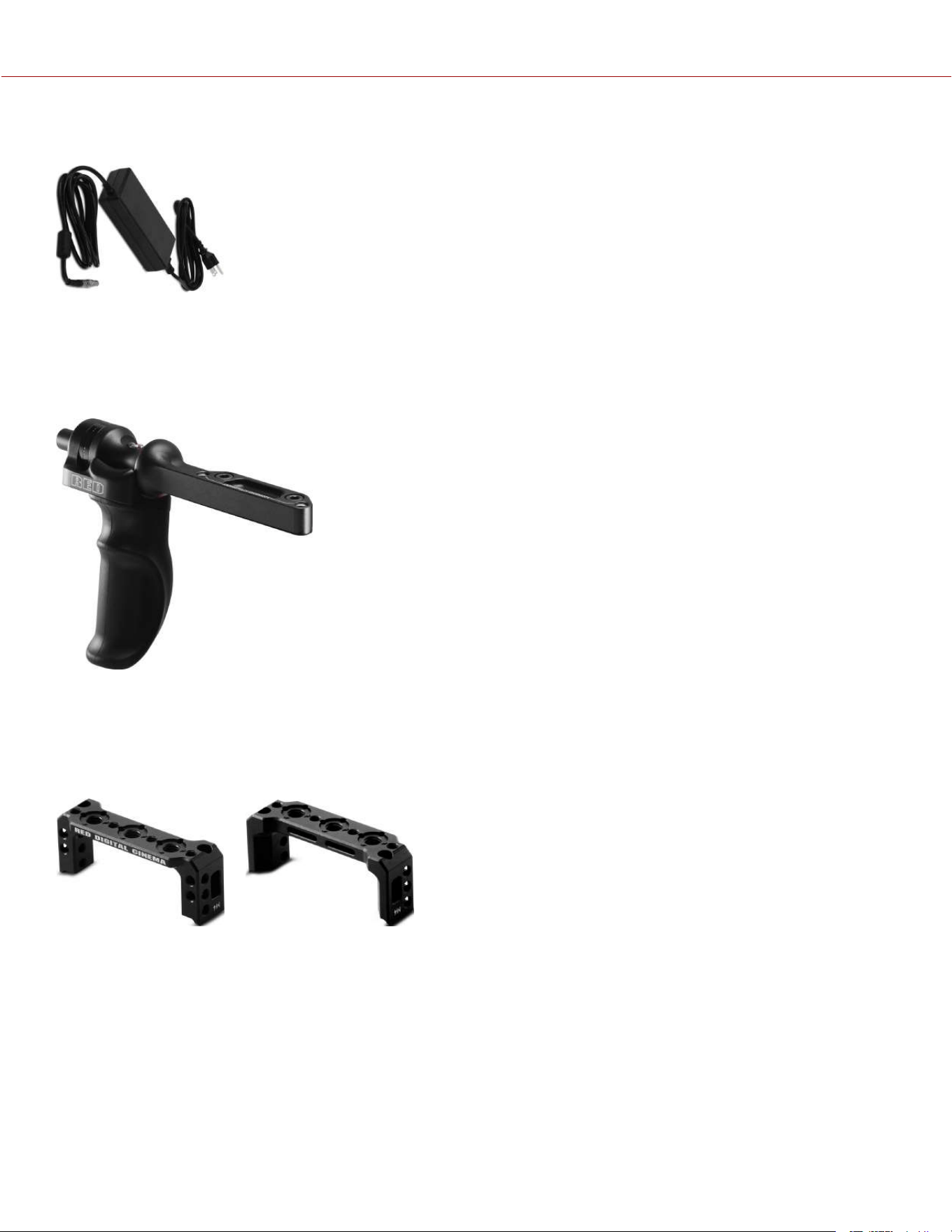
KOMODO-X
™
POWER ADAPTOR
The KOMODO-X 150-Watt AC power adaptor connects to the camera's port to provide DC
power for operating the camera and for recharging the attached REDVOLT® MICRO-V
Battery.
The camera charges the battery when the camera is off and the power adaptor is connected.
OUTRIGGER HANDLE
The Outrigger Handle offers a low profile, 360° adjustable ergonomic pistol grip and integrated Record Start/Stop
button. Mounted to the Top Handle Port on your camera, the Outrigger Handle provides comfort, stability, and
additional 1/4-20 mounting points for your peripheral camera components. The built-in Record button puts Start/Stop
functionality right at your fingertips. You are always ready to capture the perfect shot.
The Outrigger Handle is ideal for shooters who use one hand on the handle for grip and record button access, and the
other for lens adjustments or support.
KOMODO
®
WING GRIP
The KOMODO Wing Grip offers comfort and utility for carrying or shooting with your KOMODO.
Featuring an ergonomic machined grip with tactical 1/4-20 mounting points. It is lightweightand offers a seamless low-
profilehand-held option.
The KOMODO Wing Grip is a simple handle and that provides extra mounting options for your camera.
COPYRIGHT © 2023 RED.COM, LLC 955-0218, REV A | 272
KOMODO-X
®
OPERATION GUIDE
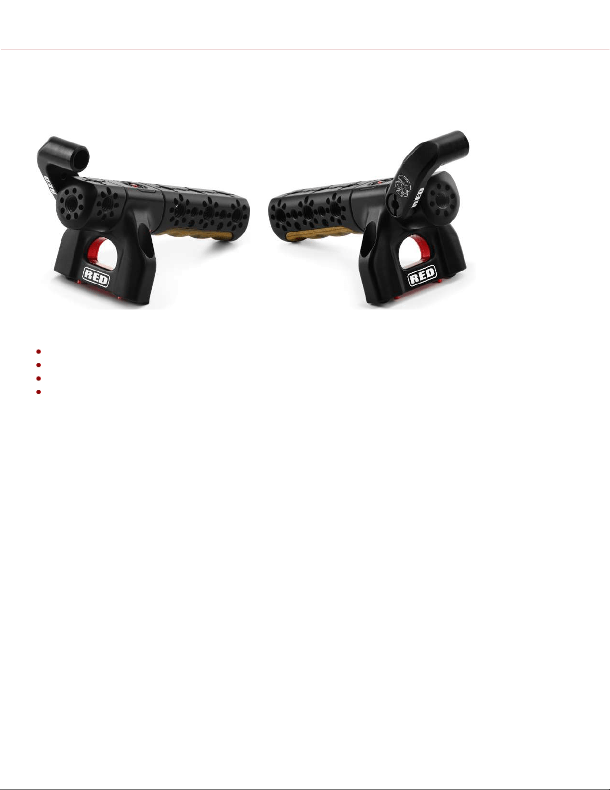
RED® COMPACT TOP HANDLE AND EXTENSIONS
The RED
®
Compact Top Handle easily mounts to the top of the KOMODO-X or V-RAPTOR camera bodies while
offering a combination of comfort and utility for carrying or shooting with your camera.
This top-mounted machined handle features ergonomic Bocote wood inlays with camera trigger control.
The handle includes:
Handle trigger
Rear 3” piece
Front 1” piece
15 mm monitor mount
COMPATIBILITY: The RED Compact Top Handle is not compatible with DSMC®, DSMC2® or RED RANGER® camera
systems.
INSTALLING THE DSMC3™ RED® TOUCH 7.0" LCD ON THE TOP HANDLE
To install the RED Touch LCD to the Top Handle:
1. Align a Top Handle Extension with front of the Top Handle.
2. Tighten the hex bolt to the Top Handle.
3. Align the 15 mm Monitor Mount extension bolt with the side 3/8-16 mount hole of the Top Handle extension.
4. Tighten the Monitor Mount bolt to the Top Handle extension.
5. Align the 15 mm hole on the Monitor rail to the 15 mm Monitor Mount.
6. Slip the 15 mm Monitor rail collar over the 15 mm Monitor mount post and tighten the knurled knob on the Monitor
rail to the desired monitor position.
COPYRIGHT © 2023 RED.COM, LLC 955-0218, REV A | 273
KOMODO-X
®
OPERATION GUIDE
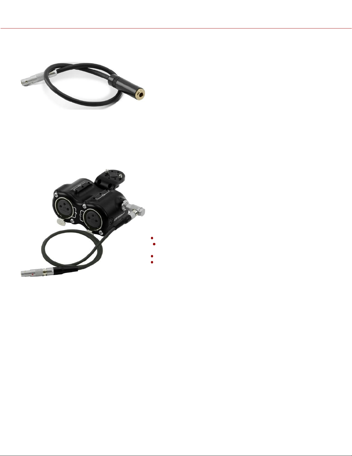
DSMC3™ RED
®
5-PIN TO SINGLE 3.5 MM ADAPTER
The DSMC3™ RED ® 5-Pin to Single 3.5 mm Adapter is a 11.3” (28.9
cm) cable designed to break out the 5-Pin Audio port to a single 3.5
mm TRS input allowing for 3.5 mm audio devices to be connected.
NOTES:
Length measured from end to end including connectors.
For replacement or additional components, such as screws, contact
COMPATIBILITY: The DSMC3™ RED 5-Pin to Single 3.5 mm Adapter is not compatible with DSMC®, DSMC2®, RED
RANGER® or KOMODO® camera systems.
DSMC3™ RED
®
5-PIN TO DUAL XLR ADAPTER
The DSMC3™ RED
®
5-Pin to Dual XLR Adapter is a compact
solution for breaking out the 5-Pin Audio port to dual 3-Pin XLR
ports. This adapter provides two industry standard XLR ports
providing 48-volt phantom power, and mic and line input that is easily
mounted to your camera.
The Dual XLR adapter's modular design provides several mounting
options for the camera.
The Dual XLR adapter includes the following:
Dual XLR adapter
L-shaped mounting bracket with 2 x 3/16 screws and 4 x
Anti-Rotate pins
A replacement ¼-20 mounting screw
18” Right angle-to-straight 5-Pin cable
To attach the L-shaped mounting bracket:
1. Determine the mounting position on or off of the camera. You may
need to re-position or remove the anti-rotate pins on the bracket depending on the orientation and position you want
to mount the bracket. You can also mount the bracket to the camera by using the replacement ¼-20 screw.
2. Screw one of the 3/16 screws in the Dual XLR adapter ensuring the anti-rotate pins line up with the desired position
of the Dual XLR adapter. Then attach the other side of the bracket to the position of your choice, confirming that the
anti-rotate pins align with holes on the camera.
NOTE: Make sure that you only pull on the knurled sleeve of the 90° angle connector on the 18” Right angle-to-straight
5-Pin cable when removing it from the Dual XLR adapter.
COPYRIGHT © 2023 RED.COM, LLC 955-0218, REV A | 274
KOMODO-X
®
OPERATION GUIDE
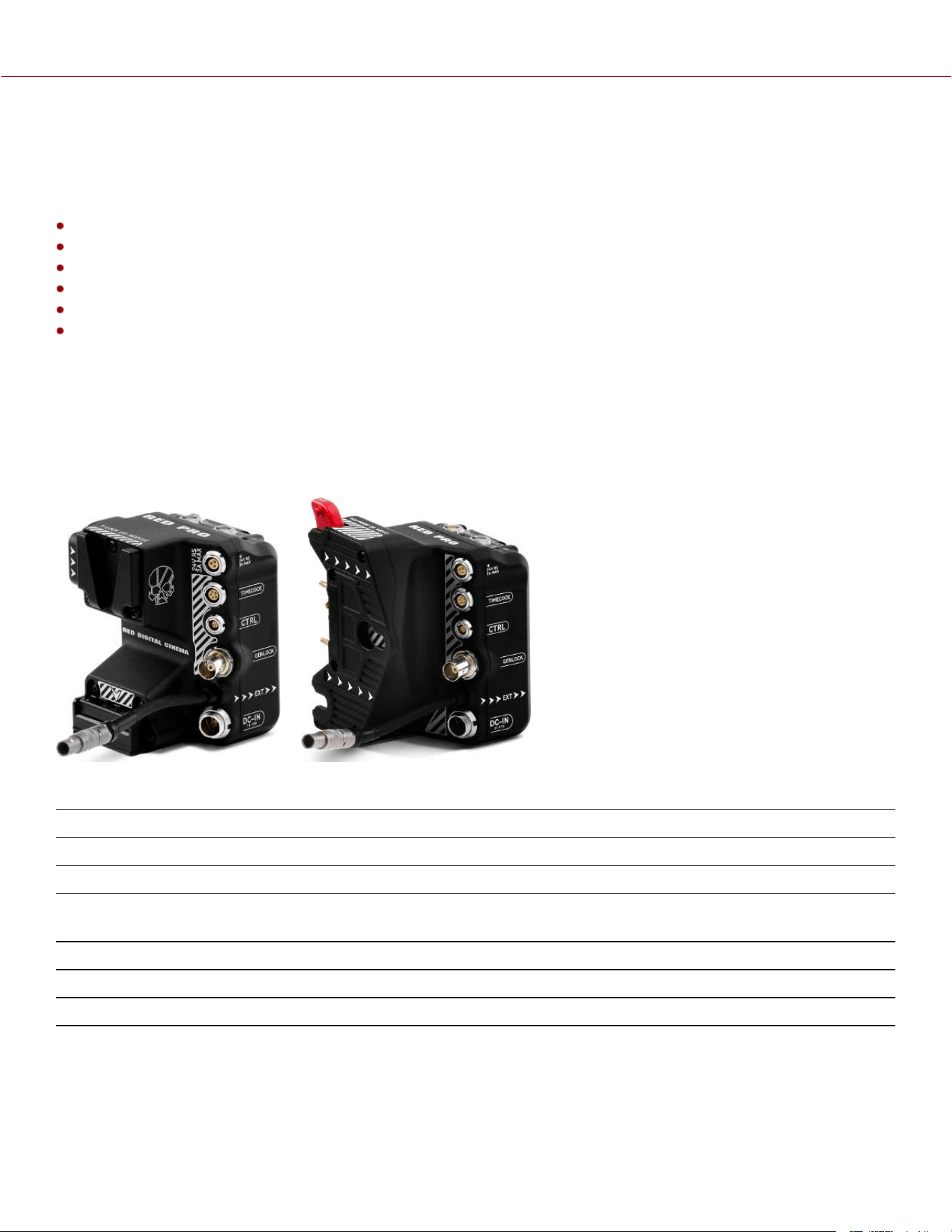
RED® PRO I/O MODULE
The RED
®
Pro I/O Module offers a variety of input/ output connections, and it also includes an industry standard V-Lock
or Gold mount to power your KOMODO-X™ with higher capacity batteries. This module mounts directly to the
KOMODO-X’s rear Micro V-Lock plate and 9-Pin EXT Port, and it offers connections for the following:
DC Power Input (DC-IN)
Genlock (BNC)
CTRL (4-Pin)
Timecode (5-pin)
1 x 3-Pin 24-volt (regulated) Fischer R/S port (3 A max)
2 x 2-Pin 12-volt (unregulated) AUX ports (3 A combined max)
The module also includes an operator-side screen which displays key power voltage and battery percentage information
(with compatible batteries) along with a power switch to cut power to the module when you want to leave a battery on
the module for long durations.
NOTE: The RED Pro V-Lock I/O Module is only compatible with KOMODO-X™. It is recommended to use 12 A Batteries
such a the REDVOLT
®
MICRO-V or REDVOLT
®
XL-V when using all AUX outputs simultaneously. When used with
REDVOLT
®
NANO-V the AUX power outputs will be disabled.
The RED
®
Pro I/O Module connects to the camera through the KOMODO-X Extension Port.
CONNECTOR CONNECTOR TYPE DETAILS
24V RS 3-pin Fischer 24-volt (regulated) Fischer R/S port (3 A max)
Timecode 5-pin Connection for external Timecode device
CTRL 4-pin 00B ODU CTRL (RS-232 Control) port for external RS-232
connection
Genlock BNC Connection for external Genlock device
Module cable 9-pin 0B ODU Attaches to the Extension Port
DC-IN 6-pin 1B socket Connection for external DC power
COPYRIGHT © 2023 RED.COM, LLC 955-0218, REV A | 275
KOMODO-X
®
OPERATION GUIDE
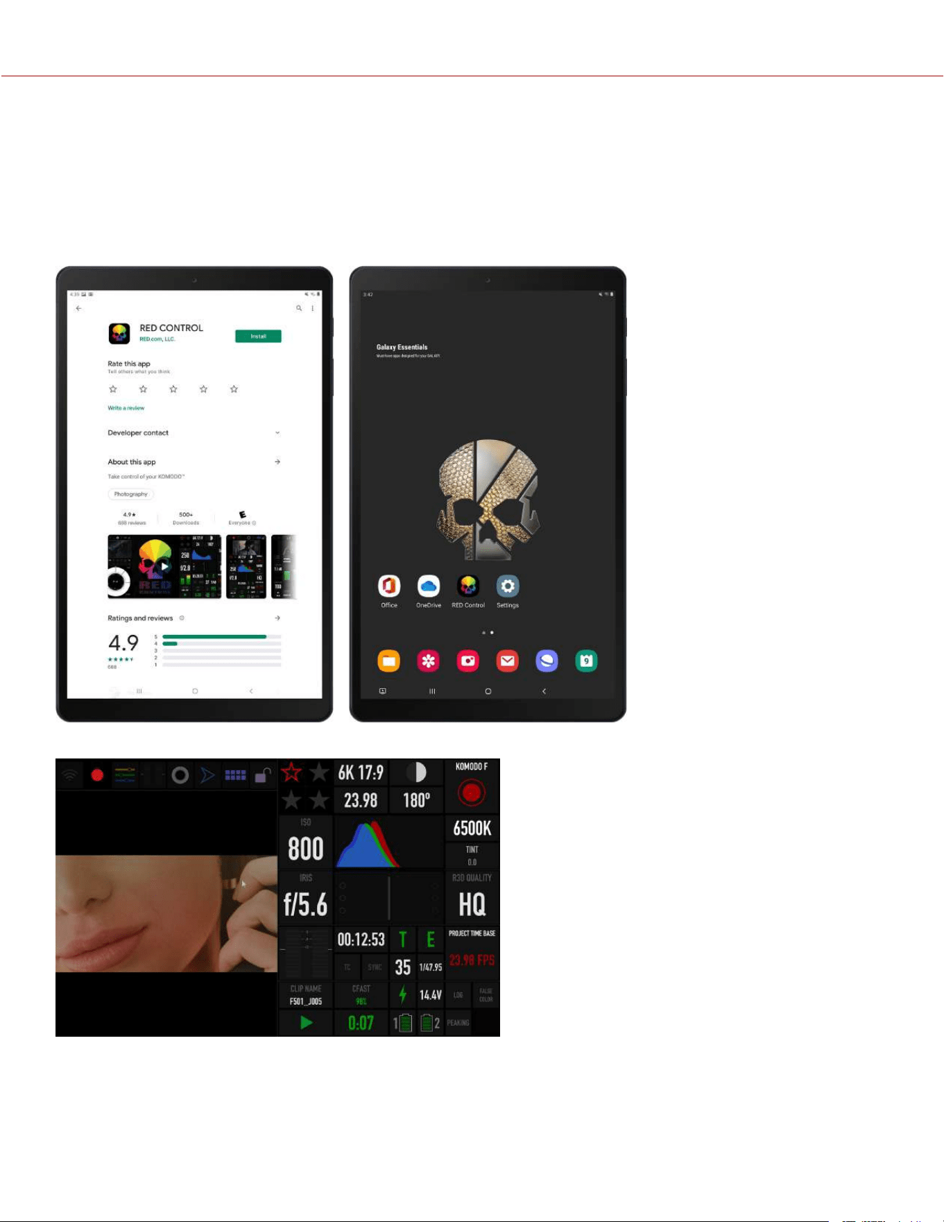
RED CONTROL APPS
The RED Control apps provides remote and tethered access to the camera from a device. Access is available through
Wi-Fi, USB-C, and Ethernet.
RED CONTROL
The RED Control app is free through the Google Play store and the Apple App store.
The RED Control app allows you to control all of the KOMODO features while viewing the image.
For more information about connecting the camera to RED Control, refer to the How To section (KOMODO Link
Adaptor).
COPYRIGHT © 2023 RED.COM, LLC 955-0218, REV A | 276
KOMODO-X
®
OPERATION GUIDE
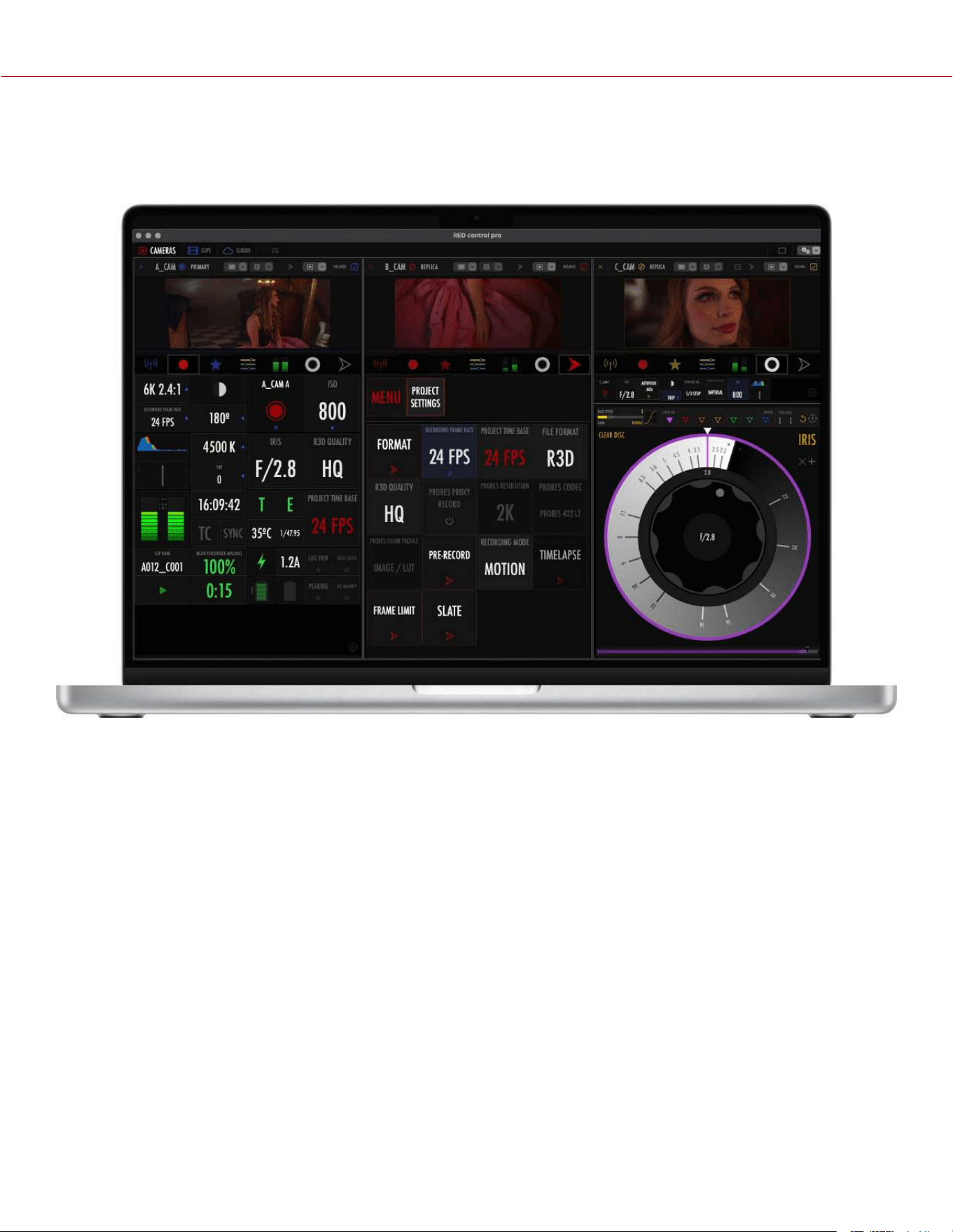
RED CONTROL PRO
RED Control Professional allows you to control multiple RED DSMC3 cameras from an Apple iPad or an Apple Mac.
RED Control Pro is a licensed application available from the Apple App Store.
RED CONNECT
RED Connect is a license enabled features available on either KOMODO-X, V-RAPTOR, or V-RAPTOR XL, which
streams full resolution live R3D video over an IP network by simply connecting the camera control unit (CCU) with an
Ethernet cable for KOMODO-X or with the RED Connect Module for V-RAPTOR and V-RAPTOR XL. This new feature
opens up an extraordinary range of creative applications from live broadcast to virtual production and true 8K VR (V-
RAPTOR, V-RAPTOR XL).
RED Connect Licenses are available with options for one year or perpetual.
For more information, refer to https://www.red.com/red-connect.
COPYRIGHT © 2023 RED.COM, LLC 955-0218, REV A | 277
KOMODO-X
®
OPERATION GUIDE