Loading ...
Loading ...
Loading ...
5
Height Adjustment (optional)
1. Measure the height of your cabinet opening. The top of
the compactor mounting screw head should be at least
1/8" (3 mm) from the top of the cabinet opening.
The rear wheels are preset for a cabinet height of 34
1
/
4
"
(87 cm). See Position “1” in the following picture.
To adjust for cabinet opening heights greater than 34
1
/
4
":
Loosen self-tapping screw just enough to clear stud
from hole in Position “1”.
Move the rear wheel and stud to Position “2” or “3”
as needed for your cabinet opening measurement:
Position “2”: 34
7
/
16
" to 34
11
/
16
" (87.5 to 88.1 cm)
Position “3”: 34
13
/
16
" to 35" (88.4 to 88.9 cm)
NOTE: To level the compactor in position “3”, you
may need to add shims under the front leveling legs.
The shims should be approximately 1/4" (6 mm) thick.
Tighten screw.
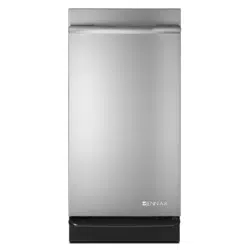
1
2
3
Locating stud
Position 1
Cabinet
Wheel bracket
assembly
Self-tapping screw (pivot)
2. Stand the compactor upright. If you are changing the rear
wheel height, move the corner posts to the opposite side
and lay the compactor on its other side. Adjust the other
rear wheel.
3. Use pliers to lower the front leveling legs away from the
compactor cabinet. Adjust the leveling legs to agree with
the position of the rear wheels.
Rear Wheel position:
“1”: 3/16" (4 mm) from bottom plate
“2”: 9/16" (14 mm) from bottom plate
“3”: 3/4" (19 mm) from bottom plate
Leveling leg
3/16" (4 mm) at
default position 1
Bottom plate
4. Stand the compactor upright. Dispose of/recycle all
packaging materials.
Undercounter Installation
Proper installation is your responsibility. Make sure you have
everything necessary for correct installation. It is the personal
responsibility and obligation of the customer to contact a
qualied installer to assure that electrical installation meets all
national and local codes and ordinances.
IMPORTANT:
To avoid damaging oor covering, slide compactor
onto cardboard or hardboard before moving compactor
across oor.
Do not allow the rear frame of the compactor to touch
the oor covering when lifting or moving compactor.
1. Move the compactor close to its nal location.
2. Remove cord clip from the back of the compactor. Plug into
a grounded 3 prong outlet.
3. Determine if you want the compactor cabinet frame or
drawer front ush with the kitchen cabinet face.
4. Rotate the two top retaining brackets 180°.
The screws are supplied in position “2”. If desired, adjust the
brackets to position “1” or “3” as described below:
If the compactor frame is to be ush with the cabinet
front, place retaining bracket screws through “1”.
If the compactor drawer front is to be ush with
the cabinet front, place retaining bracket screws
through “3”.
If the compactor is to be midway between “1” and
“3”, leave the retaining bracket screws through “2”.
1
2
3
Countertop
Retaining bracket
5. Slowly lift the front slightly and roll compactor into the
cabinet opening.
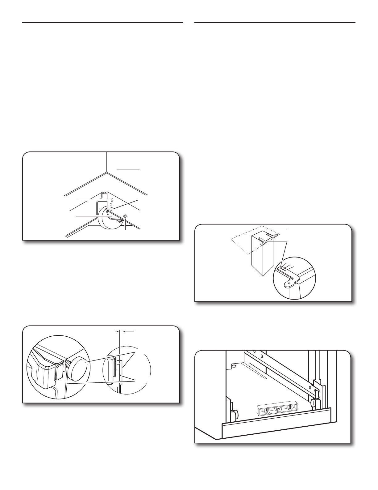
6. Adjust the leveling legs until the compactor is level and
stable. Place a level inside the bottom of the cabinet as
shown. Check the compactor leveling side to side and
back to back.
7. Using the two #8-18 x 1/2" (13 mm) screws (provided),
fasten the retaining brackets to the countertop with the
mounting screws.
Loading ...
Loading ...
Loading ...