Loading ...
Loading ...
Loading ...
User Manual
13
6 - AMPLIFIER MODULES
SRX900 products include a Class-D amplifier with built-in DSP providing optimum performance and a plug and play, easy-to-use experi-
ence. All speaker processing is performed using the internal processing, which includes the advanced LevelMax
TM
limiter suite, ensuring
proper, reliable operation under any conditions. The SRX900 Series DSP also offers a user-adjustable input section for equalization,
time alignment, and level adjustments. An LCD screen allows easy access to critical functions, including selecting operating modes,
adjusting networking parameters, and basic DSP access. Two Ethernet ports utilize Harman’s HControl protocol for external control
using standard off-the-shelf Ethernet and WiFi equipment.
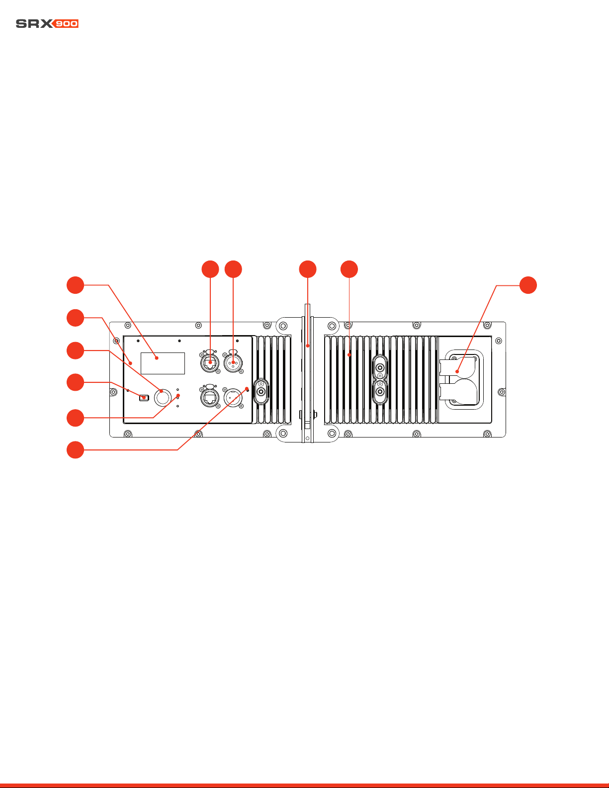
6.1 SRX906LA AND SRX910LA REAR PANEL
The SRX906LA and SRX910LA share the same rear panel layout and features. The illustrations and descriptions below apply to both
models.
1 - LCD Screen: Allows users to access speaker operating modes, DSP parameters, networking settings, and much more. Controlled
with the Encoder and the Back button. Refer to Section 15-LCD for more information on navigation and additional details on func-
tionality.
2 - Locate LED: Software-controlled LED for speaker identification. The speaker can be set to Locate mode via JBL Performance
software or from the LCD, for bidirectional visual identification of speaker. This is especially useful during setup, when physical speak-
ers are matched with software equivalents.
3 - Encoder: Controls the LCD menus and the master volume of the unit. Turn the knob to navigate through the menus. Press the
encoder to confirm an action or enter a menu. Refer to Section 15-LCD for more information on using the encoder to control the LCD
screen.
4 - Back Button: Used in conjunction with the encoder to control the LCD screen.
5 - Signal/Limit/Power LED: These three LEDs provide visual feedback for critical speaker parameters, including power state, signal,
and limiting and fault conditions. For additional information on LED functionality refer to Section 8.5 - Power LED and Section 9.1 -
Rear Panel Audio LEDs.
6 - etherCON Connectors: Allow use of standard Ethernet cable to network multiple units and control the system. An internal Ether-
net switch connects the two connectors together. Either connector can be used as the input or output. For more information on the
1
2
4
3
5
6 7 8 9
10
11
Loading ...
Loading ...
Loading ...