
2 Deutsch
Allgemeine Hinweise
Lesen Sie vor dem Einbau diese Montageanleitung
und handeln Sie danach.
Bewahren Sie die Montageanleitung für späteren Gebrauch und
für Nachbesitzer auf.
Beschreibung
Diese Montageanleitung beschreibt Einbau und Anschluss der
Rundumkennleuchte in die Maschine B 260.
Sicherheitshinweise
Gefahrenstufen
GEFAHR
● Hinweis auf eine unmittelbar drohende Gefahr, die zu schweren
Körperverletzungen oder zum Tod führt.
몇 WARNUNG
● Hinweis auf eine möglicherweise gefährliche Situation, die zu
schweren Körperverletzungen oder zum Tod führen kann.
몇 VORSICHT
● Hinweis auf eine möglicherweise gefährliche Situation, die zu
leichten Verletzungen führen kann.
ACHTUNG
● Hinweis auf eine möglicherweise gefährliche Situation, die zu
Sachschäden führen kann.
Sicherheitshinweise
ACHTUNG
Beschädigungsgefahr durch unsachgemäßen Einbau.
Bei unsachgemäßem Einbau bzw. Anschließen des Anbaugeräts
kann es zu Beschädigungen am Anbaugerät sowie am Fahrzeug
bzw. der Maschine kommen. Am Anbaugerät und Fahrzeug bzw.
Maschine können Fehlfunktionen und Ausfälle eintreten.
Lassen Sie Montage, Einbau und Anschluss des Anbaugeräts
nur von einer dafür qualifizierten Fachkraft durchführen.
ACHTUNG
Beschädigungsgefahr durch elektrostatische Entladung
(ESD)!
Elektrostatische Entladung (electrostatic discharge, ESD) kann
elektronische Bauteile beschädigen.
Ergreifen Sie vor Arbeiten an der Elektronik und Elektrik geeigne-
te Maßnahmen zur Ableitung elektrostatischer Aufladung.
ACHTUNG
Beschädigungsgefahr durch scharfkantige Gegenstände
und Verschmutzungen!
Scharfkantige bzw. verschmutzte Gegenstände können beim
Kontakt mit Bauteilen Beschädigungen wie Kratzer, Kerben und
Verformungen verursachen. Verschmutzte Werkzeuge, Lappen
und Arbeitsflächen können irreversible Verschmutzungen und
Farbveränderungen verursachen.
Verwenden Sie ausschließlich geeignete, unbeschädigte und
saubere Werkzeuge und Hilfsmittel und handeln Sie umsichtig.
Legen Sie Bauteile und Geräte ausschließlich auf sauberen, ge-
polsterten Unterlagen ab.
Aus Sicherheits- und Garantiegründen empfehlen wir, Montage,
Einbau und Anschluss durch den Kärcher-Service durchführen
zu lassen.
Bewahren Sie die Montageanleitung für späteren Gebrauch oder
für Nachbesitzer auf.
Hinweis
Beachten Sie auch die Betriebsanleitung des Fahrzeugs oder
Geräts, in welches das Anbaugerät eingebaut wird.
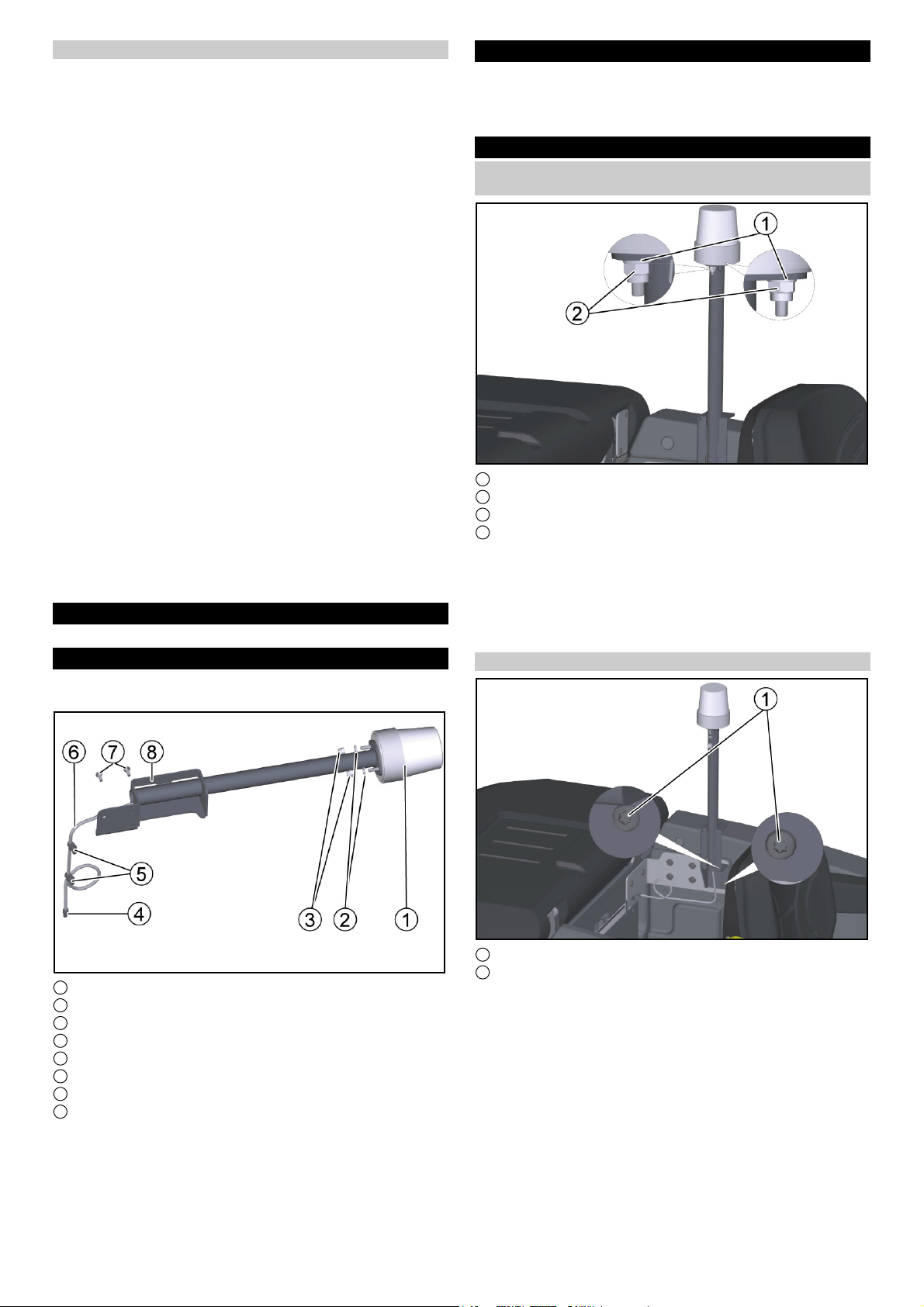
Bestellnummern und Ersatzteile
Alle Bestellnummern und Ersatzteile finden Sie in DISIS.
Übersicht
Der Anbausatz Rundumkennleuchte besteht aus folgenden Tei-
len:
1 Rundumkennleuchte orange (1 x)
2 Unterlegscheibe (2 x) und Sechskant
3 Sechskantmutter M6 (2 x)
4 Mizu-Stecker
5 Kabelbinder mit Clip
6 Kabelbaum
7 Schrauben M5x12 (2 x)
8 Halter Rundumkennleuchte
Vorarbeiten
● Programmwahlschalter in Stellung “0” drehen.
● KÄRCHER Intelligent Key (KIK) am Bedienpult abziehen.
● Batteriestecker trennen.
Montage
Rundumkennleuchte auf den Halter
Rundumkennleuchte montieren
1 Sechskantmutter M 6
2 Unterlegscheibe
3 Rundumkennleuchte
4 Halter Rundumkennleuchte
1. Den Leitungssatz der Rundumkennleuchte von oben durch
das Rohrstück schieben.
2. Die Rundumkennleuchte oben am Halter Rundumkennleuch-
te positionieren und mit der Unterlegscheibe und der Sechs-
kantmutter M 6 (2x) fixieren.
(Anzugsdrehmoment: 6Nm)

English 3
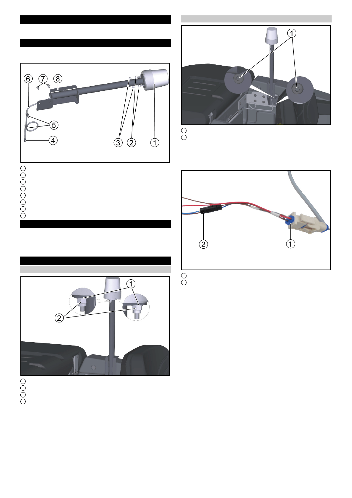
Rundumkennleuchte montieren
1
Halter Rundumkennleuchte
2
Schrauben M5x12
1. Den Halter Rundumkennleuchte mit der Schraube M 5 x 12 (2 x) fi-
xieren.
2. Den Kabelbaum der Rundumkennleuchte so weit abhängen, dass er
ohne Durchhang mit den Mizu-Stecker mit dem Adapter des Geräte-
kabelbaum verbunden werden kann.
1
Adapter Gerätekabelbaum
2
Mizu-Stecker
3. Den Kabelbaum der Rundumkennleuchte kürzen, abisolieren und mit
einem Quetschverbinder vercrimpen.
Hinweis
Auf die richtige Zuordnung der Kabelfarben (blau-blau und braun-braun)
achten.
4. Die Schrumpfschläuche der Quetschverbinder mit einem Heißluft-
föhn schrumpfen.
5. Den Mizu-Stecker in den Adapter Gerätekabelbaum stecken.
6. Den Kabelbaum mit dem Kabelbinder mit Clip (2 x) am Frischwasser-
tank fixieren.
1
Kabelbinder mit Clip
Anbausatz aktivieren
Hinweis
Zur Aktivierung des Anbausatzes wird der rote KIK benötigt.
1. Den roten KIK auflegen.
2. Den Info-Button drücken.
3. Das Menü “Anbausätze” auswählen.
4. Mit dem Info-Button auf den Anbausatz “Rundumkennleuchte”
drehen.
5. Den Info-Button drücken und den Anbausatz “Rundumkenn-
leuchte” aktivieren.
Nacharbeiten
● Ablassschlauch Schmutzwasser am Schmutzwassertank ein-
hängen.
● Deckel des Schmutzwassertanks schließen.
● Batteriestecker zusammenstecken (Maschinen ohne einge-
bautes Ladegerät).
● Masseleitung an den Minuspol der Batterie montieren (Ma-
schinen mit eingebautem Ladegerät).
Funktionsprüfung
1. Die Batterie anklemmen.
2. Das Gerät einschalten.
3. Den Knopf “Rundumkennleuchte” auf dem Bedienfeld drü-
cken.
4. Die Funktion von “Rundumkennleuchte” kontrollieren.
General notes
Read and adhere to these installation instructions
before installation.
Keep these installation instructions for future use and for future
owners.
Description
These installation instructions describe the installation and con-
nection of the flashing beacon in the machine B 260.
Safety instructions
Hazard levels
DANGER
● Indication of an imminent threat of danger that will lead to se-
vere injuries or even death.
몇 WARNING
● Indication of a potentially dangerous situation that may lead to
severe injuries or even death.
몇 CAUTION
● Indication of a potentially dangerous situation that may lead to
minor injuries.
ATTENTION
● Indication of a potentially dangerous situation that may lead to
damage to property.
4 English
Safety instructions
ATTENTION
Risk of damage due to improper installation.
Improper installation or connecting up of the attachment can
damage the attachment as well as the vehicle or the machine.
Malfunctions and failures can occur on the attachment and the
vehicle or machine.
Have the assembly, installation and connecting up of the attach-
ment carried out only by a qualified specialist.
ATTENTION
Risk of damage due to electrostatic discharge (ESD)!
Electrostatic discharge (ESD) can damage electronic compo-
nents.
Take suitable measures to discharge the electrostatic charge be-
fore all work on the device electronics.
ATTENTION
Risk of damage due to sharp-edged objects and soiling!
Sharp-edged or dirty objects can cause damage such as scratch-
es, notches and deformation when coming into contact with de-
vice components. Dirty tools, cloths and work surfaces can cause
irreversible soiling and discolouration.
Use only suitable, undamaged and clean tools and auxiliary ma-
terials and exercise care when working. Place components and
devices only on clean, padded surfaces.
For safety and warranty reasons, we recommend that you have
Kärcher Service perform the assembly, installation and connec-
tion.
Keep these installation instructions for future reference or for fu-
ture owners.
Note
Also adhere to the operating instructions for the vehicle or device
in which the attachment is installed.
Order numbers and spare parts
You can find all order numbers and spare parts in DISIS.
Overview
The flashing beacon attachment kit consists of the following
parts:
1 Flashing beacon, orange (1 x)
2 Washer (2 x) and hexagonal head
3 Hexagon nut M6 (2 x)
4 Mizu connector
5 Cable tie with clip
6 Cable harness
7 M5x12 screw (2 x)
8 Flashing beacon holder
Preparatory work
● Turn the programme selection switch to the “0” position.
● Pull out the KÄRCHER Intelligent Key (KIK) on the control
panel.
● Disconnect the battery plug.
Installation
Install the flashing beacon on the flashing beacon
holder
1 M 6 hexagon nut
2 Washer
3 Flashing beacon
4 Flashing beacon holder
1. Push the cable set of the flashing beacon through the pipe
section from above.
2. Position the flashing beacon on top of the flashing beacon
holder and affix it with the washer and the hexagon nut M 6
(2x).
(Tightening torque: 6Nm)
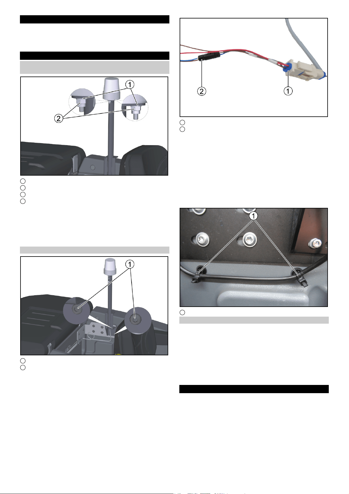
Install the flashing beacon
1 Flashing beacon holder
2 Screws M5x12
1. Affix the holder of the flashing beacon using the
M 5 x 12 screw (2 x).
2. Unhook the cable harness of the flashing beacon so far that it
can be connected with the Mizu connectors with the adapter
of the device cable harness without slack.

Français 5
1 Adapter, device cable harness
2 Mizu connector
3. Shorten the cable harness of the flashing beacon, strip it and
crimp it with a crimp connector.
Note
Make sure the cable colours (blue-blue and brown-brown) are as-
signed correctly.
4. Shrink the shrink sleeves of the crimp connectors with a hot air
gun.
5. Plug the Mizu connector into the device cable harness adapt-
er.
6. Secure the cable harness to the fresh water tank using the ca-
ble tie with clip (2 x).
1 Cable tie with clip
Activating the attachment kit
Note
The red KIK is required for activating the attachment kit.
1. Fit the red KIK.
2. Press the Info button.
3. Select the “Attachment kits” menu.
4. Turn to the attachment kit “Flashing beacon” with the Info but-
ton.
5. Press the Info button and activate the attachment kit “Flashing
beacon”.
Rework
● Hook the waste water drain hose onto the waste water tank.
● Close the cover of the waste water tank.
● Connect the battery connector (machines without built-in
charger).
● Install the ground wire on the negative pole of the battery (ma-
chines with built-in charger).
Function test
1. Connect the battery.
2. Switch the device on.
3. Press the “Flashing beacon” button on the control panel.
4. Check the function of “Flashing beacon”.
Remarques générales
Veuillez lire ces instructions de montage avant l’ins-
tallation et agissez en conséquence.
Conservez ces instructions de montage pour une utilisation ulté-
rieure et pour le propriétaire suivant.
Description
Ces instructions de montage décrivent l’installation et le raccor-
dement du gyrophare dans la machine B 260.
Consignes de sécurité
Niveaux de danger
DANGER
● Indique un danger immédiat qui peut entraîner de graves bles-
sures corporelles ou la mort.
몇 AVERTISSEMENT
● Indique une situation potentiellement dangereuse qui peut en-
traîner de graves blessures corporelles ou la mort.
몇 PRÉCAUTION
● Indique une situation potentiellement dangereuse qui peut en-
traîner des blessures légères.
ATTENTION
● Indique une situation potentiellement dangereuse qui peut en-
traîner des dommages matériels.
Consignes de sécurité
ATTENTION
Risque d’endommagement dû à une installation incorrecte.
Une installation ou un raccordement incorrect(e) de l’accessoire
peut l’endommager, ainsi que le véhicule ou la machine. Des dys-
fonctionnements et des pannes peuvent survenir sur l’accessoire
et le véhicule ou la machine.
Confiez le montage, l’installation et le raccordement de l’acces-
soire uniquement à un spécialiste qualifié à cet effet.
ATTENTION
Risque d'endommagement par décharge électrostatique
(ESD) !
Une décharge électrostatique (electrostatic discharge, ESD) peut
endommager les sous-ensembles électroniques.
Prendre les mesures nécessaires pour décharger les charges
électrostatiques du système électronique et électrique avant les
travaux.
ATTENTION
Risque d'endommagement dû aux objets tranchants et aux
encrassements !
En cas de contact avec les sous-ensembles, les objets tran-
chants ou encrassés peuvent provoquer des dommages tels que
des rayures, des entailles et des déformations. Les outils, chif-
fons et plans de travail encrassés peuvent provoquer des encras-
sements et des changement de couleur irréversibles.
Utiliser exclusivement des outils et des moyens auxiliaires adap-
tés, non endommagés et propres et agir avec prudence. Déposer
les sous-ensembles et les appareils uniquement sur des sup-
ports propres et rembourrés.
Pour des raisons de sécurité et de garantie, nous recommandons
de confier le montage, l’installation et le raccordement au person-
nel de service Kärcher.
Conservez ces instructions de montage pour une utilisation ulté-
rieure ou pour le propriétaire suivant.
Remarque
Tenez compte également du manuel d’utilisation du véhicule ou
de l’appareil dans lequel l’accessoire est monté.
6Français
Références et pièces de rechange
Vous trouverez toutes les références et pièces de rechange dans
le DISIS.
Aperçu
Le kit de montage du gyrophare se compose des pièces
suivantes :
1 Gyrophare orange (1 x)
2 Rondelle (2 x) et vis hexagonale
3 Écrou hexagonal M6 (2 x)
4 Fiche Mizu
5 Serre-câble avec clip
6 Faisceau de câbles
7 Vis M5x12 (2 x)
8 Support du gyrophare
Travaux préliminaires
● Tourner le sélecteur de programme en position « 0 ».
● Retirer la KÄRCHER Intelligent Key (KIK) du pupitre de com-
mande.
● Débrancher la fiche de la batterie.
Montage
Monter le gyrophare sur le support du gyrophare
1 Écrou hexagonal M 6
2 Rondelle
3 Gyrophare
4 Support du gyrophare
1. Pousser le kit de câbles du gyrophare par le haut à travers le
morceau de tube.
2. Positionner le gyrophare en haut du support de gyrophare et
le fixer avec la rondelle et les écrous hexagonaux M 6 (2x).
(Couple de serrage : 6Nm)
Monter le gyrophare
1 Support du gyrophare
2 Vis M5x12
1. Fixer le support du gyrophare avec la vis M 5 x 12 (2 x).
2. Décrocher le faisceau de câbles du gyrophare jusqu'à ce qu'il
puisse être connecté sans fléchir avec la fiche Mizu à l'adap-
tateur du faisceau de câbles de l'appareil.
1 Adaptateur faisceau de câble de l’appareil
2 Fiche Mizu
3. Raccourcir le faisceau de câbles du gyrophare, le dénuder et
le sertir avec un connecteur à sertir.
Remarque
Veiller à l’affectation correcte des couleurs de câble (bleu-bleu et
marron-marron).
4. Rétrécir les gaines thermorétractables des connecteurs à ser-
tir avec un pistolet à air chaud.
5. Brancher la fiche Mizu dans l'adaptateur du faisceau de câbles
de l'appareil.
6. Fixer le faisceau de câbles au réservoir d'eau propre à l'aide
du serre-câble avec clip (2 x).

Español 7
1 Serre-câble avec clip
Activer le kit de montage
Remarque
Le KIK rouge est nécessaire pour activer le kit de montage.
1. Mettre le KIK rouge.
2. Appuyer sur le bouton Info.
3. Sélectionner le menu « Kits de montage ».
4. Tourner le bouton d'information sur le kit de montage
« Gyrophare ».
5. Appuyer sur le bouton d'information et activer le kit de mon-
tage « Gyrophare ».
Travaux ultérieurs
● Accrocher le flexible de vidange des eaux usées au bac d’eau
sale.
● Fermer le couvercle du bac d’eau sale.
● Monter la fiche de la batterie (machines sans chargeur inté-
gré).
● Monter le câble de masse sur le pôle moins de la batterie (ma-
chines avec chargeur intégré).
Test de fonctionnement
1. Brancher la batterie.
2. Démarrer l’appareil.
3. Appuyer sur le bouton « Gyrophare » sur le tableau de com-
mande.
4. Contrôler le fonctionnement de « Gyrophare ».
Avisos generales
Lea estas instrucciones de montaje antes del mismo
y sígalas.
Conserve las instrucciones de montaje para su uso posterior o
para futuros propietarios.
Descripción
Estas instrucciones de montaje describen la instalación y la co-
nexión de la lámpara de advertencia omnidireccional en la má-
quina B 260.
Instrucciones de seguridad
Niveles de peligro
PELIGRO
● Aviso de un peligro inminente que produce lesiones corporales
graves o la muerte.
몇 ADVERTENCIA
● Aviso de una posible situación peligrosa que puede producir le-
siones corporales graves o la muerte.
몇 PRECAUCIÓN
● Aviso de una posible situación peligrosa que puede producir le-
siones corporales leves.
CUIDADO
● Aviso de una posible situación peligrosa que puede producir
daños materiales.
Instrucciones de seguridad
CUIDADO
Peligro de daños debido a una instalación incorrecta.
Una instalación o conexión incorrectas del accesorio pueden da-
ñarlo y dañar también el vehículo o la máquina. Pueden produ-
cirse averías y fallos de funcionamiento en el accesorio, el
vehículo o la máquina.
El montaje, la instalación y la conexión del accesorio deberán en-
cargarse exclusivamente a un personal especialista cualificado.
CUIDADO
Peligro de daños por descargas electrostáticas (ESD).
Las descargas electrostáticas (electrostatic discharge, ESD)
pueden dañar los componentes eléctricos.
Antes de realizar cualquier trabajo en el sistema electrónico y
eléctrico, tome las medidas pertinentes para disipar las cargas
electrostáticas.
CUIDADO
Peligro de daños por objetos con bordes afilados y sucie-
dad.
Los objetos con bordes afilados o sucios pueden provocar da-
ños, si entran en contacto con los componentes, como arañazos,
muescas y deformaciones. Las herramientas, superficies de tra-
bajo y paños sucios pueden provocar manchas y decoloraciones
irreversibles.
Utilice únicamente herramientas e instrumentos adecuados, en
buen estado y limpios y utilícelos de forma prudente. Deposite
los componentes y los equipos únicamente sobre bases limpias
y acolchadas.
Por motivos relacionados con la garantía y la seguridad, reco-
mendamos que el montaje, la instalación y la conexión los realice
el servicio técnico de Kärcher.
Conserve las instrucciones de montaje para su uso posterior o
para futuros propietarios.
Nota
También debe tenerse en cuenta el manual de instrucciones del
vehículo o el equipo en el que se va a montar el accesorio.
Referencias de pedido y recambios
En DISIS encontrará todas las referencias de pedido y recam-
bios.
Vista general
El juego de montaje de la lámpara de advertencia omnidireccio-
nal consta de las siguientes partes:
1 Lámpara de advertencia omnidireccional (1 unidad)
2 Arandela (2 unidades) y cabeza hexagonal
3 Tuerca hexagonal M6 (2 unidades)
4 Conector Mizu
5 Abrazadera de cables con clip
6 Mazo de cables
7 Tornillos M5x12 (2 unidades)
8 Soporte de la lámpara de advertencia omnidireccional
8 Español
Trabajos previos
● Gire el selector de programas a la posición “0”.
● Extraiga la KÄRCHER Intelligent Key (KIK) del terminal de
control.
● Desconectar el conector de la batería.
Montaje
Montaje de la lámpara de advertencia omnidireccional
en su soporte
1 Tuerca hexagonal M 6
2 Arandela
3 Lámpara de advertencia omnidireccional
4 Soporte de la lámpara de advertencia omnidireccional
1. Deslizar desde arriba el conjunto de cables de la lámpara de
advertencia omnidireccional en la sección de tubo.
2. Posicionar la lámpara de advertencia omnidireccional sobre
su soporte y fijarla con la arandela y la tuerca hexagonal M 6
(2 unidades).
(Par de apriete: 6 Nm).
Montaje de la lámpara de advertencia omnidireccional
1 Soporte de la lámpara de advertencia omnidireccional
2 Tornillos M5x12
1. Fijar el soporte de la lámpara de advertencia omnidireccional
con el tornillo M 5 x 12 (2 unidades).
2. Desenganchar el mazo de cables de la lámpara de adverten-
cia omnidireccional hasta que pueda conectarse sin comba al
adaptador del mazo de cables del equipo con los conectores
Mizu.
1 Adaptador del mazo de cables del equipo
2 Conector Mizu
3. Acortar el mazo de cables de la lámpara de advertencia omni-
direccional, aislarlo y engarzarlo con un conector tipo crimp.
Nota
Asegurarse de que los colores de los cables (azul-azul y marrón-
marrón) estén correctamente asignados.
4. Encoger los tubos termorretráctiles de los conectores tipo
crimp con la ayuda de un secador de aire caliente.
5. Insertar el conector Mizu en el adaptador del arnés del mazo
de cables del equipo.
6. Fijar el mazo de cables al depósito de agua fresca con la abra-
zadera de cables con clip (2 unidades).
1 Abrazadera de cables con clip
Activar el juego de montaje
Nota
El KIK rojo es necesario para activar el juego de montaje.
1. Colocar el KIK rojo.
2. Pulsar el botón de información.
3. Seleccionar el menú «Juegos de montaje».
4. Girar con el botón de información en el juego de montaje
«Lámpara de advertencia omnidireccional».
5. Pulsar el botón de información y activar el juego de montaje
«Lámpara de advertencia omnidireccional».
Trabajos de repaso
● Enganche la manguera de desagüe de aguas residuales al
depósito de agua sucia.
● Cierre la tapa del depósito de agua sucia.
● Enchufe el conector de la batería (máquinas sin cargador in-
corporado).
● Monte el cable de tierra en el polo negativo de la batería (má-
quinas con cargador incorporado).

Русский 9
Comprobación de funcionamiento
1. Conectar la batería.
2. Conectar el equipo.
3. Pulsar el botón "Lámpara de advertencia omnidireccional" en
el campo de control.
4. Comprobar la función de "Lámpara de advertencia omnidirec-
cional".
Общие указания
Перед установкой следует ознакомиться с
настоящей инструкцией по монтажу и
действовать в соответствии с ней.
Сохранить инструкцию по монтажу для дальнейшего
пользования и для следующего владельца.
Описание
В данной инструкции по монтажу описан процесс установки и
подключения проблескового маячка на машине B 260.
Указания по технике безопасности
Степень опасности
ОПАСНОСТЬ
● Указание относительно непосредственно грозящей
опасности, которая приводит к тяжелым травмам или к
смерти.
몇 ПРЕДУПРЕЖДЕНИЕ
● Указание относительно возможной потенциально
опасной ситуации, которая может привести к тяжелым
травмам или к смерти.
몇 ОСТОРОЖНО
● Указание на потенциально опасную ситуацию, которая
может привести к получению легких травм.
ВНИМАНИЕ
● Указание относительно возможной потенциально
опасной ситуации, которая может повлечь за собой
материальный ущерб.
Указания по технике безопасности
ВНИМАНИЕ
Опасность повреждения из-за неправильной
установки.
Неправильная установка или подключение навесного
оборудования может привести к повреждению навесного
оборудования, а также транспортного средства или
машины. На навесном оборудовании и транспортном
средстве или машине могут возникнуть сбои и отказы.
Монтаж, установка и подключение навесного оборудования
должны выполняться только квалифицированными
специалистами.
ВНИМАНИЕ
Опасность повреждения вследствие
электростатического разряда (ЭСР)!
Электростатический разряд (electrostatic discharge, ЭСР)
может причинить вред электронному оборудованию.
Перед проведением любых работ с электроникой и
электрооборудованием следует предпринять
соответствующие меры для отвода
электростатического заряда.
ВНИМАНИЕ
Опасность повреждения об острые и грязные
предметы!
Острые или грязные предметы при контакте с
конструктивными узлами могут стать причиной таких
повреждений, как царапины, зазубрины или деформация.
Грязные инструменты, ветошь и рабочие поверхности
могут вызвать необратимые загрязнения и изменения
цвета.
Использовать только подходящие, неповрежденные и
чистые инструменты и вспомогательные средства, при
обращении соблюдать осторожность. Конструктивные
узлы и устройства класть только на чистое основание с
мягкой подкладкой.
Из соображений безопасности и для сохранения гарантии
мы рекомендуем поручить монтаж, установку и подключение
оборудования сервисной службе Kärcher.
Сохранить инструкцию по монтажу для дальнейшего
пользования или для следующего владельца.
Примечание
Соблюдать также указания, приведенные в инструкции по
эксплуатации транспортного средства или устройства,
на которое устанавливается навесное оборудование.
Номера для заказа и запасные части
Все номера для заказа и запасные части приведены в DISIS.
Обзор
Монтажный комплект проблескового маячка состоит из
следующих частей:
1 Проблесковый маячок оранжевого цвета (1 шт.)
2 Подкладная шайба (2 шт.) и шестигранник
3 Шестигранная гайка M6 (2 шт.)
4 Штекер Mizu
5 Кабельная стяжка с зажимом
6 Кабельный жгут
7 Винты M5x12 (2 шт.)
8 Держатель проблескового маячка
Предварительные работы
● Установить переключатель выбора программ в положение
«0».
●Извлечь чип-ключ KÄRCHER (KIK) из пульта управления.
●Отсоединить штекер аккумулятора.
Монтаж
Установка проблескового маячка на держатель
1 Шестигранная гайка M 6
2 Подкладная шайба

10 Русский
3 Проблесковый маячок
4 Держатель проблескового маячка
1. Протянуть кабельный жгут проблескового маячка сверху
через трубу.
2. Расположить проблесковый маячок сверху на держателе и
закрепить его с помощью подкладной шайбы и
шестигранной гайки M 6 (2 шт.).
(Момент затяжки: 6 Нм)
Установка проблескового маячка
1 Держатель проблескового маячка
2 Винты M5x12
1. Закрепить держатель проблескового маячка винтом
M 5 x 12 (2 шт.).
2. Определить длину кабельного жгута проблескового
маячка, при которой подсоединение к адаптеру
кабельного жгута устройства с помощью штекера Mizu
будет возможно без провисания.
1 Адаптер кабельного жгута устройства
2 Штекер Mizu
3. Укоротить кабельный жгут проблескового маячка, снять
изоляцию и обжать провода с помощью соединительных
гильз.
Примечание
Проследить за правильным соединением проводов по
цвету (синий-синий и коричневый-коричневый).
4. Выполнить усадку термоусадочных трубок
соединительных гильз с помощью термофена.
5. Вставить штекер Mizu в адаптер кабельного жгута
устройства.
6. Закрепить кабельный жгут на баке для чистой воды с
помощью кабельной стяжки с зажимом (2 шт.).
1 Кабельная стяжка с зажимом
Активация монтажного комплекта
Примечание
Для активации монтажного комплекта необходим красный
чип-ключ KIK.
1. Приложить красный чип-ключ KIK.
2. Нажать информационную кнопку.
3. Выбрать меню «Монтажные комплекты».
4. С помощью информационной кнопки перейти к
монтажному комплекту «Проблесковый маячок».
5. Нажать информационную кнопку и активировать
монтажный комплект «Проблесковый маячок».
Заключительные работы
● Закрепить сливной шланг для грязной воды на баке для
грязной воды.
● Закрыть крышку бака для грязной воды.
● Подсоединить штекер аккумулятора (машины без
встроенного зарядного устройства).
● Подсоединить провод массы к отрицательному полюсу
аккумулятора (машины со встроенным зарядным
устройством).
Проверка функционирования
1. Присоединить клеммы аккумулятора.
2. Включить устройство.
3. Нажать кнопку «Проблесковый маячок» на панели
управления.
4. Проверить функцию «Проблесковый маячок».


2-2-SC-A4-GS-aw19869