
Loading ...
Loading ...
Loading ...
ENGLISH
8
3. Replace the lever, positioning the chosen end under the
spring
10
. Ensure the lever is in proper contact with
thespring.
4. Replace screw and torque to 2.0-3.0N-m. Ensure proper
installation with spring return function by depressing
guard release lever
7
.
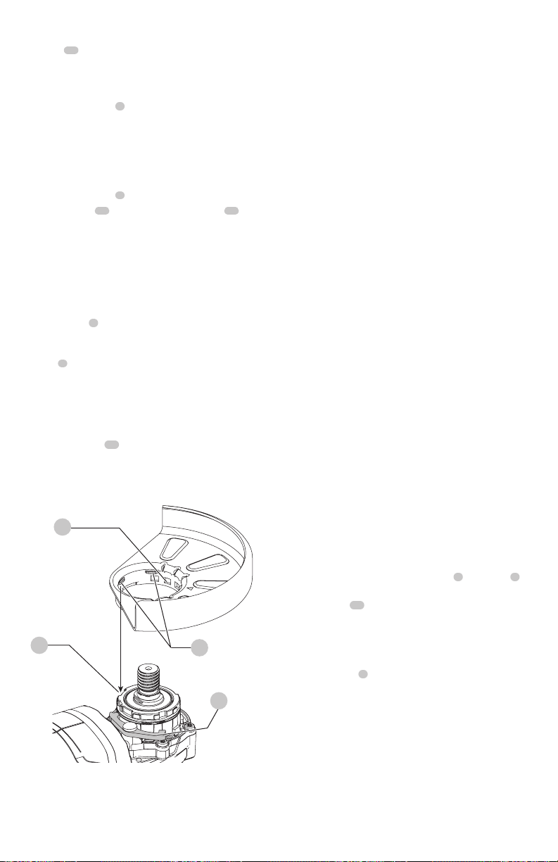
Mounting Guard (Fig. D)
CAUTION: Prior to mounting guard, ensure the screw,
lever, and spring are fitted correctly before mounting
theguard.
1. With the spindle facing the operator, press and hold the
guard release lever
7
.
2. Align the lugs
12
on the guard with the slots
13
on
the gearcasecover.
3. Push the guard down until the guard lugs engage
and rotate them in the groove on the gear case cover.
Release the guard releaselever.
4. To position the guard:
One-touch
TM
: Rotate the guard clockwise into the
desired working position. Press and hold the guard
release lever
7
to rotate the guard in the counter-
clockwisedirection.
Two-touch
TM
: Press and hold the guard release
lever
7
. Rotate the guard clockwise or counter-
clockwise into the desired working position.
NOTE: The guard body should be positioned between
the spindle and the operator to provide maximum
operatorprotection.
The guard release lever should snap into one of the
alignment holes
11
on the guard collar. This ensures
that the guard issecure.
5. To remove the guard, follow steps 1–3 of these
instructions inreverse.
7
13
12
11
Fig. D
Flanges and Wheels
WARNING: To reduce the risk of serious personal
injury, turn unit off and disconnect it from
power source before making any adjustments or
removing/installing attachments or accessories.
An accidental start-up can cause injury.
WARNING: Accessories must be rated for at least
the speed recommended on the tool warning label.
Wheels and other accessories running over their
rated accessory speed may fly apart and cause injury.
Threaded accessories must have a 5/8"-11 hub. Every
unthreaded accessory must have a 7/8" (22 mm)
arbor hole. If it does not, it may have been designed
for a circular saw and should not be used. Use only
the accessories shown in the Accessories Chart of this
manual. Accessory ratings must always be above tool
speed as shown on tool nameplate.
WARNING: Handle and store all abrasive wheels
carefully to prevent damage from thermal shock, heat,
mechanical damage, etc. Store in a dry protected area
free from high humidity, freezing temperatures or
extreme temperature changes.
Mounting Non-Hubbed Wheels (Fig. E)
WARNING: Failure to properly seat the flanges and/or
wheel could result in serious injury (or damage to the
tool or wheel).
CAUTION: Included flanges must be used with
depressed center Type 27/42 grinding wheels and
Type1/41 cutting wheels. See the Accessories Chart
for moreinformation.
WARNING: A closed, two-sided cutting wheel guard
is required when using abrasive cutting wheels or
diamond coated cutting wheels.
WARNING: Use of a damaged flange or guard or fail-
ure to use proper flange and guard can re sult in injury
due to wheel breakage and wheel contact. See the
Accessories Chart for moreinformation.
1. Place the tool on a table, guardup.
2. Install the unthreaded backing flange
3
on spindle
1
with the raised center (pilot) facing the wheel.
3. Place wheel
14
against the backing flange,
centering the wheel on the raised center (pilot) of the
backingflange.
4. While depressing the spindle lock button and with the
raised center facing the wheel, thread the threaded
locking flange
4
on spindle
a. If the wheel you are installing is 1/8" (3.0 mm) thick
or less, place the threaded locking flange on the
spindle so that the raised section (pilot) is not against
the wheel.(Fig. E).
NOTE: If the wheel spins after the clamp nut is tightened,
check the orientation of the threaded clamp nut. If a thin
wheel is installed with the pilot on the clamp nut against
the wheel, it will spin because the height of the pilot
prevents the clamp nut from holding the wheel.
NOTE: If the wheel you are installing is more than 1/8"
(3.17mm) thick, place the threaded locking flange on
Loading ...
Loading ...
Loading ...