Loading ...
Loading ...
Loading ...
English
9
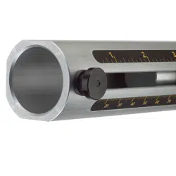
A bushing's size can quickly be checked by placing only the
bushing on the end of the cable (Reference Table). The
cable should not be able to fit through the bushing with the
jacket on and the blade should not extend past the jacket.
Refer to the Cable to Bushing Size Reference Table at the
end of this manual to match the appropiatebushing to your
cablesize.
Fig. B
4
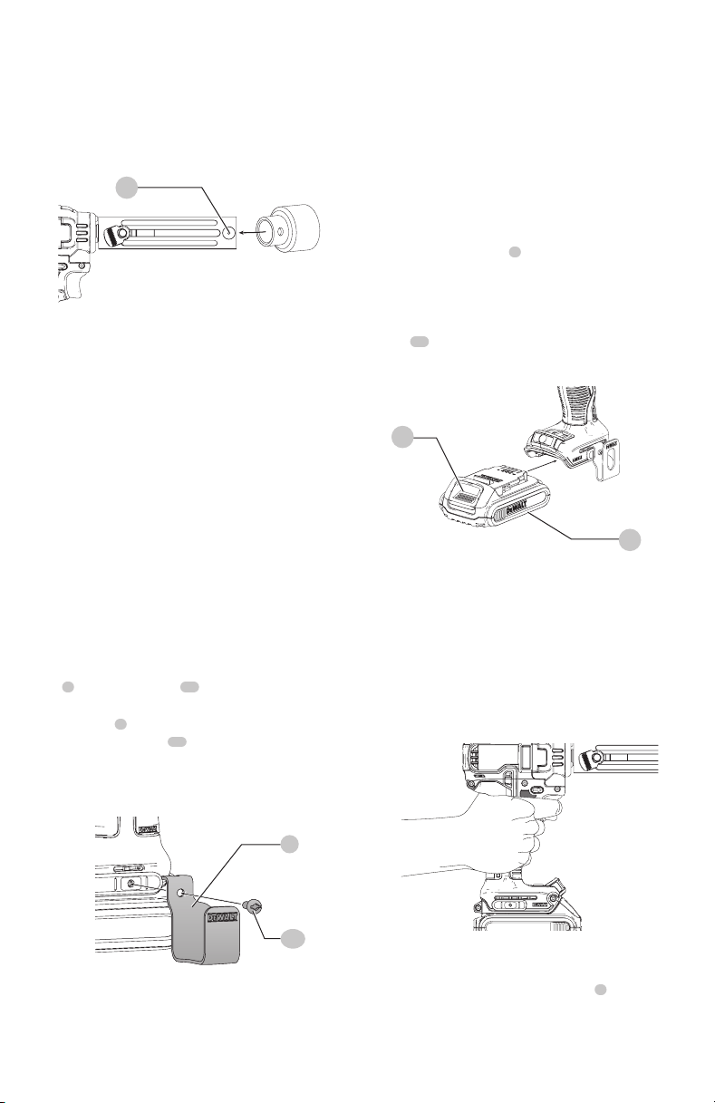
Removing and Attaching the Hang Hook
(Fig. A, C)
WARNING: To reduce the risk of serious personal
injury, do not use the tool's hang hook to hang the
tool from your body. DO NOT use the hang hook for
tethering or securing the tool to a person or object
during use. DO NOT suspend tool overhead or suspend
objects from the hanghook.
WARNING: To reduce the risk of injury from the cable
cutter falling on operators or bystanders, make sure
it is supported securely when using the hang hook,
or resting in a secure and stable location when not in
use. Be sure to keep the area below clear to reduce the
risk of the tool or off-cut material falling and striking
someone or somethingbelow.
WARNING: To reduce the risk of serious personal
injury, ensure the screw holding the hang hook
issecure.
iMPORTAnT: When attaching or replacing the hang
hook
7
, use only the screw
11
that is provided. Be sure to
securely tightenscrew.
The hang hook
7
can be be attached to either side of the
tool using only the screw
11
provided, to accommodate
left- or right- handed users. Be sure to securely
tightenscrew.
7
11
Fig. C
OPERATION
WARNING: To reduce the risk of serious personal
injury, turn unit off and remove the battery pack
before making any adjustments or removing/
installing attachments or accessories. An
accidental start-up can causeinjury.
Installing and Removing the Battery Pack
(Fig. D)
nOTE: For best results, make sure your battery pack is
fullycharged.
To install the battery pack
9
into the tool handle, align the
battery pack with the rails inside the tool’s handle and slide
it into the handle until the battery pack is firmly seated in
the tool and ensure that it does notdisengage.
To remove the battery pack from the tool, press the release
button
10
and firmly pull the battery pack out of the tool
handle. Insert it into the charger as described in the charger
section of thismanual.
Fig. D
9
10
Proper Hand Position (Fig. E)
WARNING: To reduce the risk of serious personal injury,
ALWAYS use proper hand position as shown.
WARNING: To reduce the risk of serious personal
injury, ALWAYS hold securely in anticipation of a
suddenreaction.
Proper hand position requires one hand on the
mainhandle.
Fig. E
Trigger and Directional/Lock-Off Button
(Fig. F)
The position of directional/lock-off button
2
determines
the direction of the tool rotation, as shown in figure H, and
whether the tool is locked-off. When changing the position
of the control button, be sure the trigger isreleased.
Loading ...
Loading ...
Loading ...