Owner's Handbook
Bonneville T100 (all models), Bonneville T120
(all models), Speed Twin, Street Scrambler,
Street Twin and Thruxton RS
This handbook contains information on the Triumph Bonneville T100 (all models),
Bonneville T120 (all models), Speed Twin, Street Scrambler, Street Twin and
Thruxton RS motorcycles. Always store this Owner's Handbook with the motorcycle
and refer to it for information whenever necessary.
The information contained in this publication is based on the latest information
available at the time of printing. Triumph reserves the right to make changes at any
time without prior notice, or obligation.
Not to be reproduced wholly or in part without the written permission of Triumph
Motorcycles Limited.
© Copyright 08.2019 Triumph Motorcycles Limited, Hinckley, Leicestershire, England.
Publication part number 3855663-EN issue 1
1

2
Table of Contents
This handbook contains a number of different sections. The table of contents below
will help you find the beginning of each section where, in the case of the major
sections, a further table of contents will help you find the specific subject required.
Foreword 3
Safety First 7
Warning Label Locations 14
Parts Identification 16
Serial Numbers 28
General Information 29
How to Ride the Motorcycle 79
Accessories, Loading and Passengers 91
Maintenance and Adjustment 95
Cleaning and Storage 151
Specifications - Bonneville T100 and Bonneville T120 161
Specifications - Bonneville T120 Ace and Diamond 165
Specifications - Bonneville Bud Ekins 169
Specifications - Street Scrambler 173
Specifications - Speed Twin 177
Specifications - Street Twin 181
Specifications - Thruxton RS 185
Index 189
Approval Information 193
Foreword
3
Foreword
Warnings, Cautions and
Notes
Throughout this Owner's Handbook
particularly important information is
presented in the following form:
Warning
This warning symbol identifies special
instructions or procedures, which if
not correctly followed could result in
personal injury, or loss of life.
Caution
This caution symbol identifies special
instructions or procedures, which,
if not strictly observed, could result
in damage to, or destruction of,
equipment.
Note
This note symbol indicates points of
particular interest for more efficient and
convenient operation.
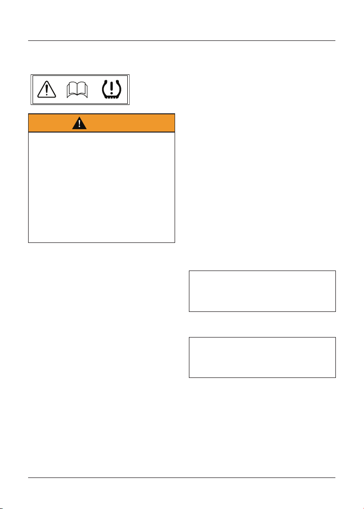
Warning Labels
At certain areas of the motorcycle,
the symbol (above) can be seen. The
symbol means 'CAUTION: REFER TO THE
HANDBOOK' and will be followed by a
pictorial representation of the subject
concerned.
Never attempt to ride the motorcycle
or make any adjustments without
reference to the relevant instructions
contained in this handbook.
For the location of all labels bearing this
symbol, see the Warning Label Locations
section. Where necessary, this symbol
will also appear on the pages containing
the relevant information.
Maintenance
To ensure a long, safe and trouble free
life for your motorcycle, maintenance
should only be carried out by an
authorised Triumph dealer.
Only an authorised Triumph dealer
will have the necessary knowledge,
equipment and skills to maintain your
Triumph motorcycle correctly.
To locate your nearest authorised
Triumph dealer, visit the Triumph web
site at www. triumph. co. uk or telephone
the authorised distributor in your
country. Their address is given in the
service record book that accompanies
this handbook.
Foreword
4
Noise Control System
Tampering with the noise control
system is prohibited.
Owners are warned that the law may
prohibit:
1. The removal or rendering
inoperative by any person other
than for purposes of maintenance,
repair or replacement, of any device
or element of design incorporated
into any new vehicle for the purpose
of noise control prior to its sale or
delivery to the ultimate purchaser
or while it is in use and,
2. the use of the vehicle after such
device or element of design
has been removed or rendered
inoperative by any person.
Among those acts presumed to
constitute tampering are the acts listed
below:
• Removal of, or puncturing the
muffler, baffles, header pipes or any
other component which conducts
exhaust gases.
• Removal of, or puncturing of any
part of the intake system.
• Lack of proper maintenance.
• Replacing any moving parts of the
vehicle, or parts of the exhaust or
intake system, with parts other than
those specified by the manufacturer.
Owner's Handbook
Warning
This Owner's Handbook, and all other
instructions that are supplied with
your motorcycle, should be considered
a permanent part of your motorcycle
and should remain with it even if your
motorcycle is subsequently sold.
All riders must read this Owner's
Handbook and all other instructions
which are supplied with your
motorcycle, before riding, in order to
become thoroughly familiar with the
correct operation of your motorcycle's
controls, its features, capabilities and
limitations.
Do not lend your motorcycle to others
as riding when not familiar with
your motorcycle's controls, features,
capabilities and limitations can lead to
an accident.
Thank you for choosing a Triumph
motorcycle. This motorcycle is the
product of Triumph's use of proven
engineering, exhaustive testing,
and continuous striving for superior
reliability, safety and performance.
Please read this Owner's Handbook
before riding in order to become
thoroughly familiar with the correct
operation of your motorcycle's controls,
its features, capabilities and limitations.
This Owner's Handbook includes safe
riding tips, but does not contain all the
techniques and skills necessary to ride a
motorcycle safely.

Foreword
5
Triumph strongly recommends that
all riders undertake the necessary
training to ensure safe operation of this
motorcycle.
This Owner's Handbook is available from
your local dealer in:
• English
• US English
• Chinese
• Dutch
• French
• German
• Italian
• Japanese
• Portuguese
• Spanish
• Swedish
• Thai.
The languages available for this Owner's
Handbook are dependent on the specific
motorcycle model and country.
Talk to Triumph
Our relationship with you does not end
with the purchase of your Triumph. Your
feedback on the buying and ownership
experience is very important in helping
us develop our products and services
for you.
Please help us by ensuring your
authorised Triumph dealership has your
email address and registers this with us.
You will then receive an online customer
satisfaction survey invitation to your
email address where you can give us
this feedback.
Your Triumph Team.

Foreword
6
This page intentionally left blank
Safety First
7
Safety First
The Motorcycle
All Models Except Street Scrambler
Warning
This motorcycle is designed for on-
road use only. It is not suitable for off-
road use.
Off-road operation could lead to loss
of control of the motorcycle resulting
in an accident causing injury or loss of
life.
Street Scrambler Only
Warning
The motorcycles are designed for on-
road and light off-road use. Light off-
road use includes use on unpaved, dirt
or gravel roads, but does not include
riding on any motocross course,
any off-road competition (such as
motocross or enduro riding), or riding
off-road with a passenger.
Light off-road use does not include
jumping the motorcycle or riding over
obstacles. Do not attempt to jump
over any bumps or obstacles. Do not
attempt to ride over any obstacles.
Extreme off-road use could lead to
loss of motorcycle control and an
accident.
Warning
This motorcycle is not designed to tow
a trailer or be fitted with a sidecar.
Fitting a sidecar and/or a trailer
may result in loss of control and an
accident.
Warning
This motorcycle is designed for use
as a two-wheeled vehicle capable of
carrying a rider on his/her own, or a
rider and one passenger (subject to
a passenger seat and footrests being
fitted).
The total weight of the rider, and any
passenger, accessories and luggage
must not exceed the maximum
load limit stated in the relevant
Specifications section.
Safety First
8
Fuel and Exhaust Fumes
Warning
PETROL IS HIGHLY FLAMMABLE:
Always turn off the engine when
refuelling.
Do not refuel or open the fuel filler cap
while smoking or in the vicinity of any
open (naked) flame.
Take care not to spill any petrol on
the engine, exhaust pipes or silencers
when refuelling.
If petrol is swallowed, inhaled or
allowed to get into the eyes, seek
immediate medical attention.
Spillage on the skin should be
immediately washed off with soap and
water and clothing contaminated with
petrol should immediately be removed.
Burns and other serious skin
conditions may result from contact
with petrol.
Warning
Never start the engine or run the
engine in a confined area.
Exhaust fumes are poisonous and can
cause loss of consciousness and death
within a short period of time.
Always operate the motorcycle in the
open air or in an area with adequate
ventilation.
Helmet and Clothing
Warning
When riding the motorcycle, both
rider and passenger (on models where
carrying a passenger is permitted)
must always wear appropriate clothing
including a motorcycle helmet, eye
protection, gloves, boots, trousers
(close fitting around the knee and
ankle) and a brightly coloured jacket.
During off-road use (on models
suitable for off-road use), the rider
must always wear appropriate clothing
including trousers and boots.
Brightly coloured clothing will
considerably increase a rider's
(or passenger's) visibility to other
operators of road vehicles.
Although full protection is not possible,
wearing correct protective clothing
can reduce the risk of injury when
riding.

Safety First
9
Warning
A helmet is one of the most important
pieces of riding gear as it offers
protection against head injuries. You
and your passenger's helmet should
be carefully chosen and should
fit you or your passenger's head
comfortably and securely. A brightly
coloured helmet will increase a rider's
(or passenger's) visibility to other
operators of road vehicles.
An open face helmet offers some
protection in an accident though a full
face helmet will offer more.
Always wear a visor or approved
goggles to help vision and to protect
your eyes.
Parking
Warning
Always switch off the engine and
remove the ignition key before
leaving the motorcycle unattended.
By removing the key, the risk of use
of the motorcycle by unauthorised or
untrained persons is reduced.
When parking the motorcycle, always
remember the following:
- Engage first gear to help prevent the
motorcycle from rolling off the stand.
- The engine and exhaust system
will be hot after riding. DO NOT park
where pedestrians, animals and/
or children are likely to touch the
motorcycle.
- Do not park on soft ground or on
a steeply inclined surface. Parking
under these conditions may cause
the motorcycle to fall over.
For further details, please refer to the
'How to Ride the Motorcycle' section of
this Owner's Handbook.
Safety First
10
Parts and Accessories
Warning
Owners should be aware that the
only approved parts, accessories
and conversions for any Triumph
motorcycle are those which carry
official Triumph approval and are fitted
to the motorcycle by an authorised
dealer.
In particular, it is extremely hazardous
to fit or replace parts or accessories
whose fitting requires the dismantling
of, or addition to, either the electrical
or fuel systems and any such
modification could cause a safety
hazard.
The fitting of any non-approved
parts, accessories or conversions may
adversely affect the handling, stability
or other aspect of the motorcycle
operation that may result in an
accident causing injury or death.
Triumph does not accept any liability
whatsoever for defects caused by
the fitting of non-approved parts,
accessories or conversions or
the fitting of any approved parts,
accessories or conversions by non-
approved personnel.
Triumph does not accept any liability
whatsoever for defects caused by
the fitting of non-approved parts,
accessories or conversions or the fitting
of any approved parts, accessories or
conversions by non-approved personnel.
Maintenance and Equipment
Warning
Consult your authorised Triumph
dealer whenever there is doubt as to
the correct or safe operation of this
Triumph motorcycle.
Remember that continued operation of
an incorrectly performing motorcycle
may aggravate a fault and may also
compromise safety.
Warning
Make sure all equipment that is
required by law is installed and
functioning correctly.
The removal or alteration of the
motorcycle’s lights, silencers, emission
or noise control systems can violate
the law.
Incorrect or improper modification may
adversely affect the handling, stability
or other aspect of the motorcycle
operation, which may result in an
accident causing injury or death.
Warning
If the motorcycle is involved in an
accident, collision or fall, it must be
taken to an authorised Triumph dealer
for inspection and repair.
Any accident can cause damage to
the motorcycle that, if not correctly
repaired, may cause a second accident
that may result in injury or death.
Safety First
11
Riding
Warning
Never ride the motorcycle when
fatigued or under the influence of
alcohol or other drugs.
Riding when under the influence of
alcohol or other drugs is illegal.
Riding when fatigued or under the
influence of alcohol or other drugs
reduces the rider's ability to maintain
control of the motorcycle and may
lead to loss of control and an accident.
Warning
All riders must be licenced to operate
the motorcycle.
Operation of the motorcycle without
a licence is illegal and could lead to
prosecution.
Operation of the motorcycle without
formal training in the correct riding
techniques that are necessary to
become licenced is dangerous and may
lead to loss of motorcycle control and
an accident.
Warning
Always ride defensively and wear
the protective equipment mentioned
elsewhere in this foreword.
Remember, in an accident, a
motorcycle does not give the same
impact protection as a car.
Warning
This Triumph motorcycle should be
operated within the legal speed limits
for the particular road travelled.
Operating a motorcycle at high speeds
can be potentially dangerous since the
time available to react to given traffic
situations is greatly reduced as road
speed increases.
Always reduce speed in potentially
hazardous driving conditions such as
bad weather or heavy traffic.
Warning
Continually observe and react to
changes in road surface, traffic and
wind conditions. All two-wheeled
vehicles are subject to external forces
which may cause an accident. These
forces include but are not limited to:
- Wind draft from passing vehicles
- Potholes, uneven or damaged road
surfaces
- Bad weather
- Rider error.
Always operate the motorcycle at
moderate speed and away from
heavy traffic until you have become
thoroughly familiar with its handling
and operating characteristics. Never
exceed the legal speed limit.
Safety First
12
Handlebars and Footrests
Warning
The rider must maintain control of the
motorcycle by keeping hands on the
handlebars at all times.
The handling and stability of a
motorcycle will be adversely affected
if the rider removes their hands from
the handlebars, resulting in loss of
motorcycle control and an accident.
Warning
The rider and passenger (if applicable)
must always use the footrests
provided, during operation of the
motorcycle.
By using the footrests, both rider
and passenger will reduce the risk
of inadvertent contact with any
motorcycle components and will
also reduce the risk of injury from
entrapment of clothing.
Warning
Use of a motorcycle with bank angle
indicators worn beyond the maximum
limit will allow the motorcycle to be
banked to an unsafe angle. Therefore,
always replace the bank angle
indicators before they are worn to
their maximum limit.
Banking to an unsafe angle may cause
instability, loss of motorcycle control
and an accident.
Details of the bank angle wear limits
can be found in the Maintenance and
Adjustment section.
Warning
The bank angle indicators must not
be used as a guide to how far the
motorcycle may be safely banked.
This depends on many various
conditions including, but not limited
to, road surface, tyre condition
and weather. Banking to an unsafe
angle may cause instability, loss of
motorcycle control and an accident.
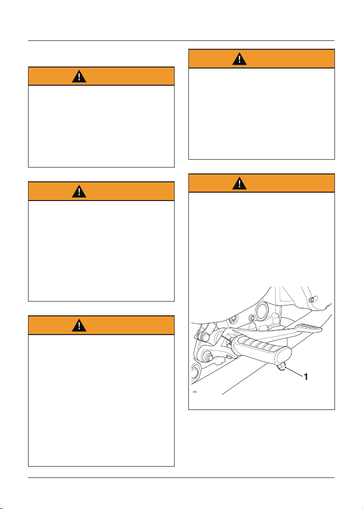
Warning
When banking and the bank angle
indicator, attached to the rider's
footrest, makes contact with the
ground, the motorcycle is nearing its
bank angle limit. A further increase of
the banking angle is unsafe.
Banking to an unsafe angle may cause
instability, loss of motorcycle control
and an accident.
citc
1
1. Bank angle indicator

Foreword
13
This page intentionally left blank
Warning Label Locations
14
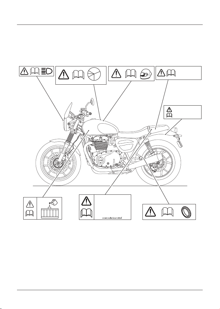
Warning Label Locations
The labels detailed on this and the following pages draw your attention to important
safety information in this handbook. Before riding, make sure that all riders have
understood and complied with all the information to which these labels relate.
R.P.M.
DAILY SAFETY CHECKS
TÄGLICHE SICHERHEITSKONTROLLEN
CONTROLES DE SECURITE QUOTIDIENS
CHEQUEOS DE SEGURIDAD DIARIOS
VERIFICAÇÕES DIÁRIAS DE SEGURANÇA
VERIFICHE GIORNALIERE DI SICUREZZA
DAGELIJSKE VEILIGHEIDSINSPECTIES
DAGLIG SÄKERHETSKONTROLL
運行前点検
6
7
8
1234
5
MAX LOAD
5 kg (11 lbs)
MAX LOAD
3 kg (6.6 lbs)
1. Headlight (page 144)
2. Running-In (page 77)
3. Helmet (page 8)
4. Luggage Rack (if fitted) (page 75)
5. Panniers (if fitted) (page 91)
6. Coolant (page 105)
7. Daily Safety Checks (page 78)
8. Tyres (page 134)
Warning Label Locations
15
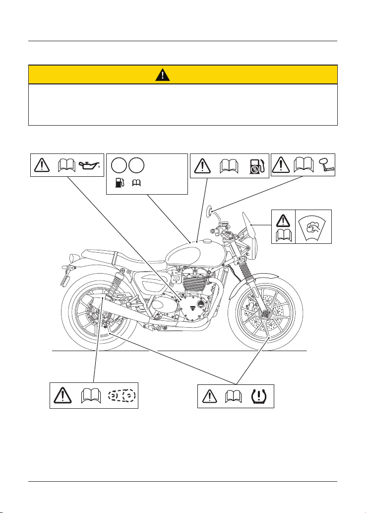
Warning Label Locations (continued)
Caution
All warning labels and decals, with the exception of the Running-in label, are fitted
to the motorcycle using a strong adhesive. In some cases, labels are installed prior
to an application of paint lacquer. Therefore, any attempt to remove the warning
labels will cause damage to the paintwork or bodywork.
12
6 7
RON/ROZ 95 min. 91
E5 E10
3900691
Unleaded fuel only
Carburant sans plomb
Gasolina sin plomo
Bleifreies Benzin
Endast blyfri bensin
Benzina senza piombo
Ongelode Brandstof
Combustival sem schumbo
34
5
1. Engine Oil (page 101)
2. E5 and E10 Fuel (if fitted) (page 63)
3. Unleaded Fuel (page 63)
4. Mirrors (page 124)
5. Windscreen (if fitted) (page 157)
6. Drive Chain (page 111)
7. Tyre Pressure Monitoring System
(if fitted) (page 51)
Parts Identification
16
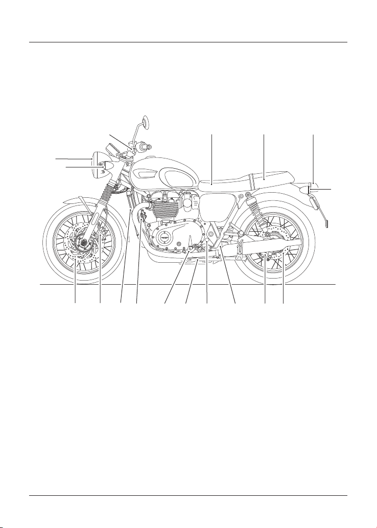
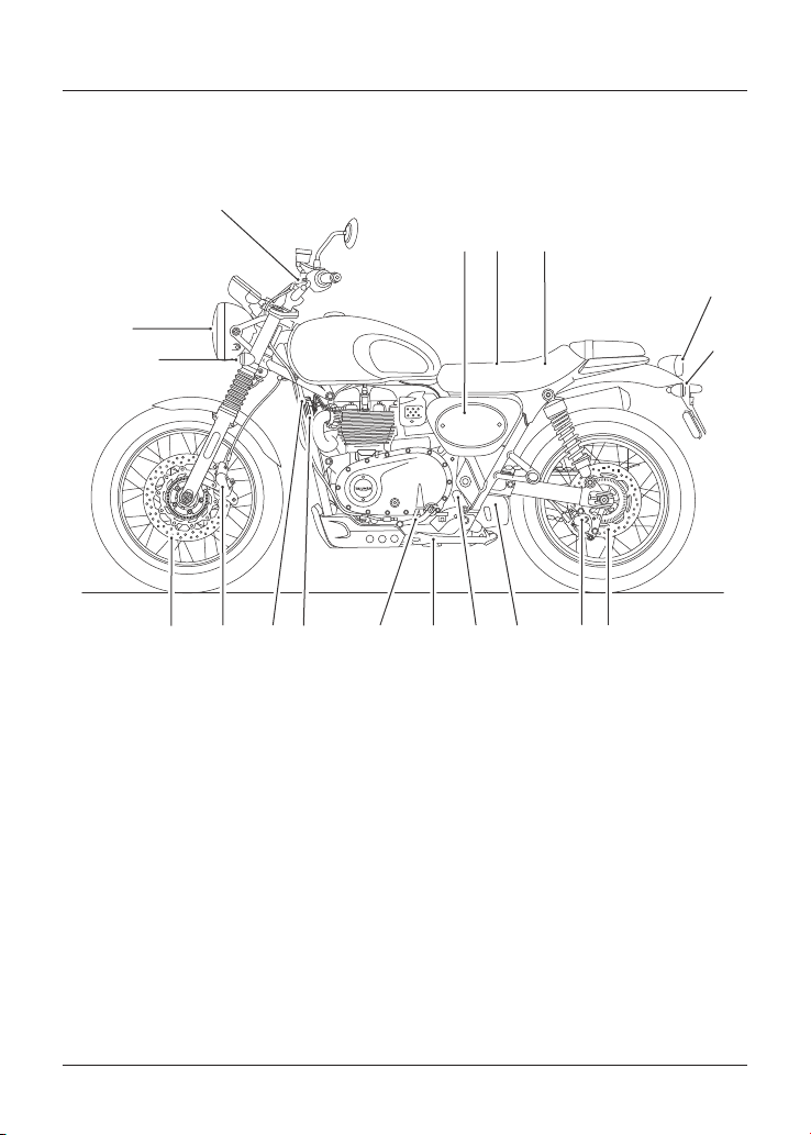
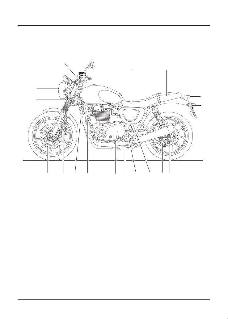
Parts Identification
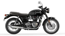
Bonneville T100 (all models) and Bonneville T120 (all models)
(Bonneville T120 shown)
1
2
3
4
5
6
7
8
91 0111213
14
15
16
17
1. Front direction indicator
2. Headlight
3. Clutch lever
4. Battery (under seat)
5. Owner’s Handbook (under seat) or
supplied separately
6. Brake/rear light
7. Rear direction indicator
8. Rear brake disc
9. Rear brake caliper
10. Coolant expansion tank
11. Coolant expansion tank cap
12. Side stand
13. Gear change pedal
14. Horn
15. Radiator
16. Front brake caliper
17. Front brake disc
Parts Identification
17
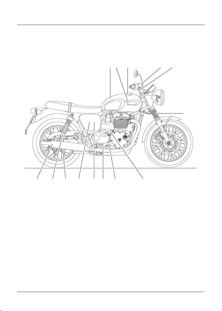
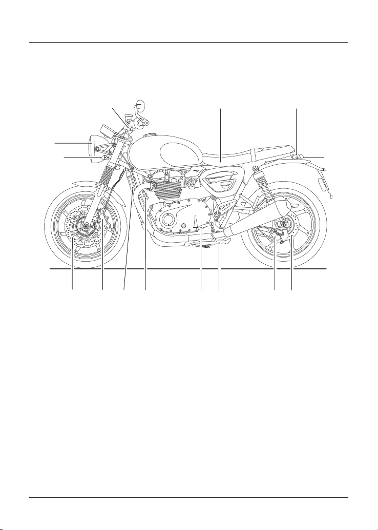
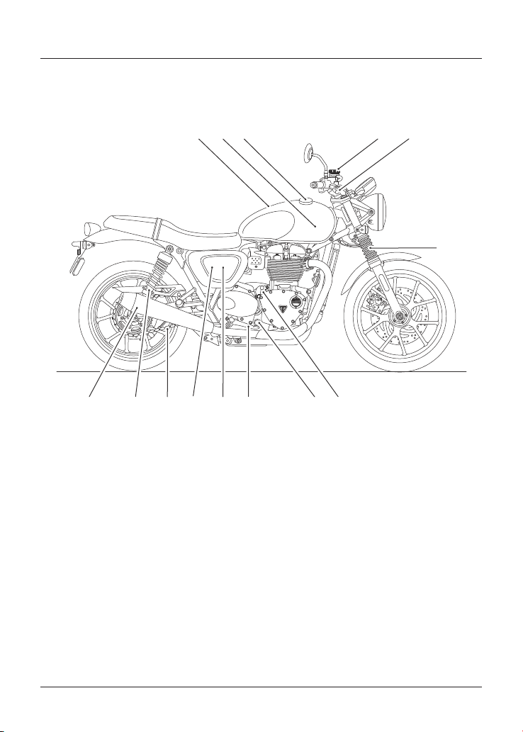
Parts Identification - Continued
Bonneville T100 (all models) and Bonneville T120 (all models)
(Bonneville T120 shown)
13
4
6
891011121314 7
52
1. Fuel tank
2. Coolant pressure cap (under fuel tank)
3. Fuel filler cap
4. Front brake fluid reservoir
5. Front brake lever
6. Front fork
7. Oil filler plug
8. Oil level sight glass
9. Rear brake pedal
10. Rear brake fluid reservoir (behind side
panel)
11. Adjustment tool (behind side panel)
12. Drive chain
13. Rear suspension unit
14. Silencer
Parts Identification
18
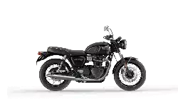
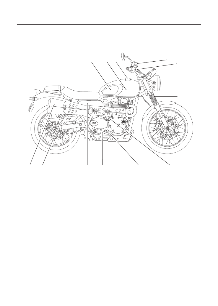
Parts Identification
Street Scrambler
1
2
3
45
6
7
8
91011
12
13
14
15
16
17
18
1. Front direction indicator
2. Headlight
3. Clutch lever
4. Adjustment tool (behind side panel)
5. Battery (under seat)
6. Owner’s Handbook (under seat)
7. Brake/rear light
8. Rear direction indicator
9. Rear brake disc
10. Rear brake caliper
11. Coolant expansion tank
12. Coolant expansion tank cap
13. Side stand
14. Gear change pedal
15. Horn
16. Radiator
17. Front brake caliper
18. Front brake disc
Parts Identification
19
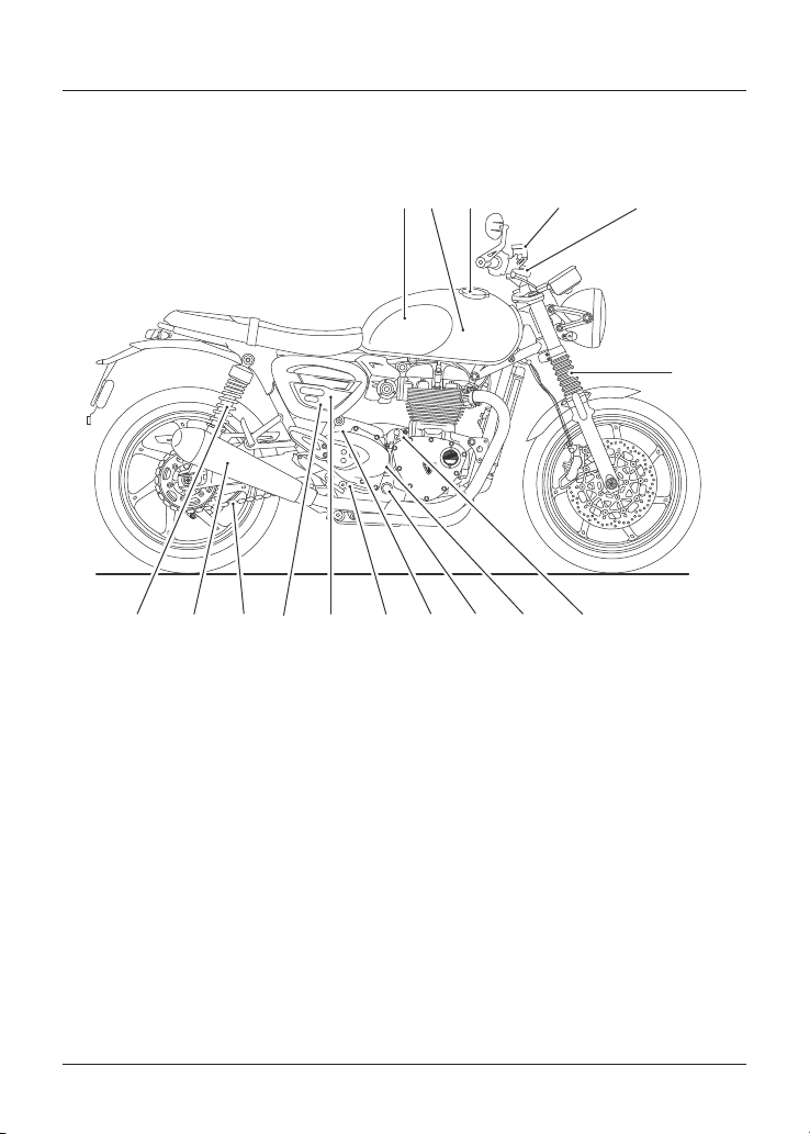
Parts Identification - Continued
Street Scrambler
6
7
8
5
12
9
10
3
11
4
12
13
1. Fuel tank
2. Coolant pressure cap (under fuel tank)
3. Fuel filler cap
4. Front brake fluid reservoir
5. Front brake lever
6. Front fork
7. Oil filler plug
8. Oil level sight glass
9. Rear brake pedal
10. Rear brake fluid reservoir (behind side
panel)
11. Drive chain
12. Rear suspension unit
13. Silencer
Parts Identification
20
Parts Identification
Speed Twin
6
1
2
3 4 5
7
891011121314
1. Front direction indicator
2. Headlight
3. Clutch lever
4. Battery (under seat)
5. Rear direction indicator
6. Brake/rear light
7. Rear brake disc
8. Rear brake caliper
9. Side stand
10. Gear change pedal
11. Horn
12. Radiator
13. Front brake caliper
14. Front brake disc
Parts Identification
21
Parts Identification - Continued
Speed Twin
1
3 45
78 9 1 0111213
6
141516
2
1. Fuel tank
2. Coolant pressure cap (under fuel tank)
3. Fuel filler cap
4. Front brake fluid reservoir
5. Front brake lever
6. Front fork
7. Oil filler plug
8. Coolant expansion tank
9. Oil level sight glass
10. Coolant expansion tank cap
11. Rear brake pedal
12. Rear brake fluid reservoir (behind side
panel)
13. Adjustment tool (behind side panel)
14. Drive chain
15. Silencer
16. Rear suspension unit
Parts Identification
22
Parts Identification
Street Twin
1
2
3
45
6
7
8
9
10111213
14
15
16
17
1. Front direction indicator
2. Headlight
3. Clutch lever
4. Battery (under seat)
5. Owner’s Handbook (under seat)
6. Brake/rear light
7. Rear direction indicator
8. Rear brake disc
9. Rear brake caliper
10. Coolant expansion tank
11. Coolant expansion tank cap
12. Side stand
13. Gear change pedal
14. Horn
15. Radiator
16. Front brake caliper
17. Front brake disc
Parts Identification
23
Parts Identification - Continued
Street Twin
1 4
6
89 1 0 11121314 7
2
3
5
1. Fuel tank
2. Coolant pressure cap (under fuel tank)
3. Fuel filler cap
4. Front brake fluid reservoir
5. Front brake lever
6. Front fork
7. Oil filler plug
8. Oil level sight glass
9. Rear brake pedal
10. Rear brake fluid reservoir (behind side
panel)
11. Adjustment tool (behind side panel)
12. Drive chain
13. Rear suspension unit
14. Silencer
Parts Identification
24
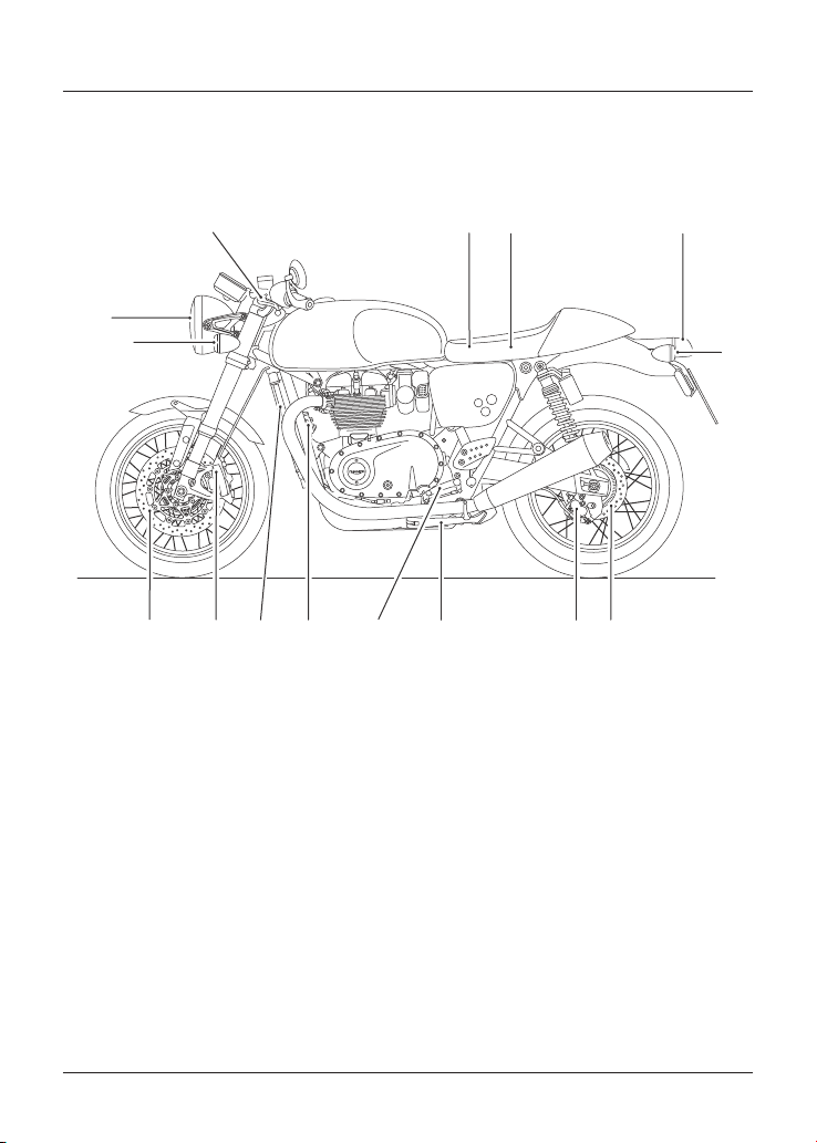
Parts Identification
Thruxton RS
7
1
2
3
4
5
6
89101112131415
1. Front direction indicator
2. Headlight
3. Clutch lever
4. Battery (under seat)
5. Owner’s Handbook (under seat)
6. Brake/rear light
7. Rear direction indicator
8. Rear brake disc
9. Rear brake caliper
10. Side stand
11. Gear change pedal
12. Horn
13. Radiator
14. Front brake caliper
15. Front brake disc
Parts Identification
25
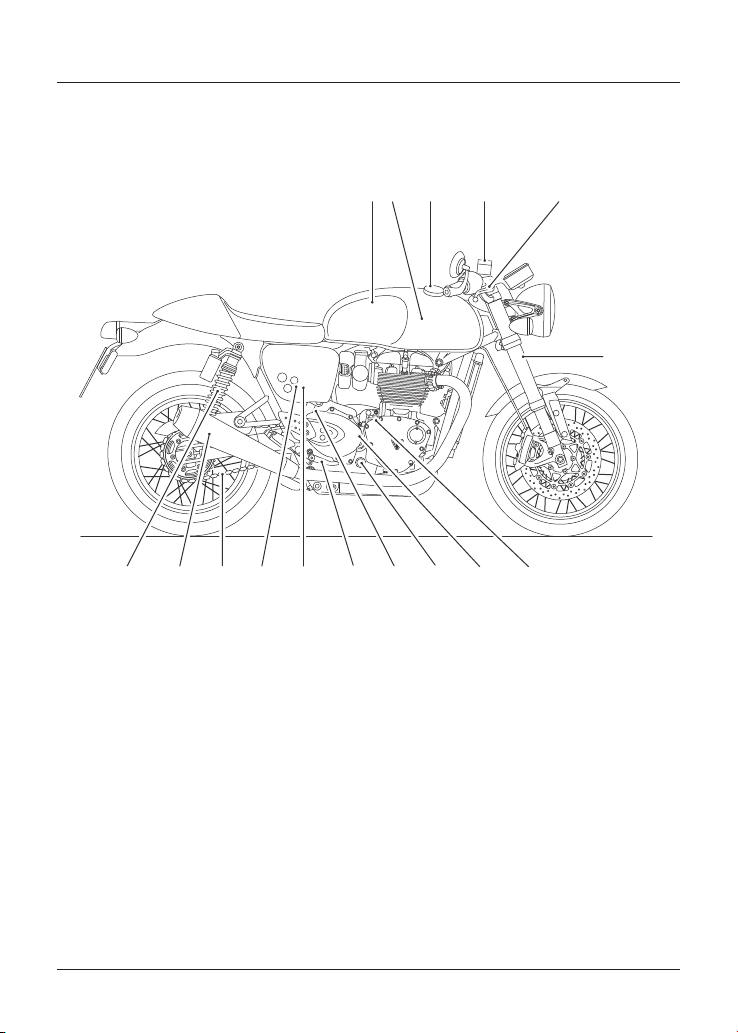
Parts Identification - Continued
Thruxton RS
1 34 5
78 9 1 0111213
6
14
15
16
2
1. Fuel tank
2. Coolant pressure cap (under fuel tank)
3. Fuel filler cap
4. Front brake fluid reservoir
5. Front brake lever
6. Front fork
7. Oil filler plug
8. Coolant expansion tank
9. Oil level sight glass
10. Coolant expansion tank cap
11. Rear brake pedal
12. Rear brake fluid reservoir (behind side
panel)
13. Adjustment tool (behind side panel)
14. Drive chain
15. Silencer
16. Rear suspension unit
Parts Identification
26
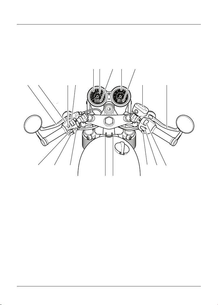
Rider View Parts Identification
Bonneville T100 (all models), Bonneville T120 (all models), Speed Twin and
Thruxton RS
2
1
3
4
5
6
78
9
15
10
11
1213
1617
14
1. Clutch lever
2. Headlight dip switch
3. SCROLL button
4. Daytime Running Lights (DRL) switch
(if fitted)
5. Speedometer
6. Warning lights
7. Trip computer/Odometer/Information
display screen
8. Tachometer
9. Information display screen
10. Front brake fluid reservoir
11. Front brake lever
12. Engine start/stop switch
13. MODE button (Bonneville T120 (all models)
only)
14. Hazard button
15. MODE button (Speed Twin and
Thruxton RS only)
16. Horn button
17. Indicator switch
Parts Identification
27
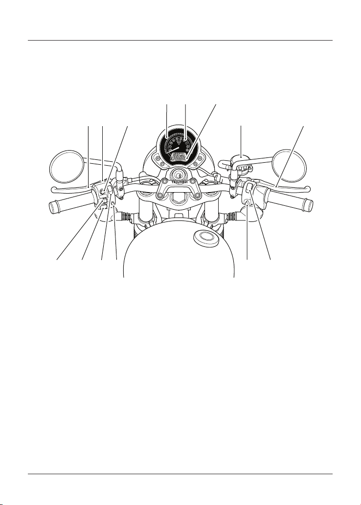
Rider View Parts Identification
Street Scrambler and Street Twin (Street Twin shown)
10
20
30
40
50
60
70
80
90
100
110
120
120
0
0
20
40
60
80
100
120
140
160
180
200
1
3
45 6
78
91 0
11
2
14 1213
1. Clutch lever
2. Headlight dip switch
3. SCROLL button
4. Speedometer
5. Warning lights
6. Odometer/Information display screen
7. Front brake fluid reservoir
8. Front brake lever
9. Engine start/stop switch
10. Hazard button
11. MODE button
12. Daytime Running Lights (DRL) switch
(if fitted)
13. Horn button
14. Direction indicator switch
Serial Numbers
28
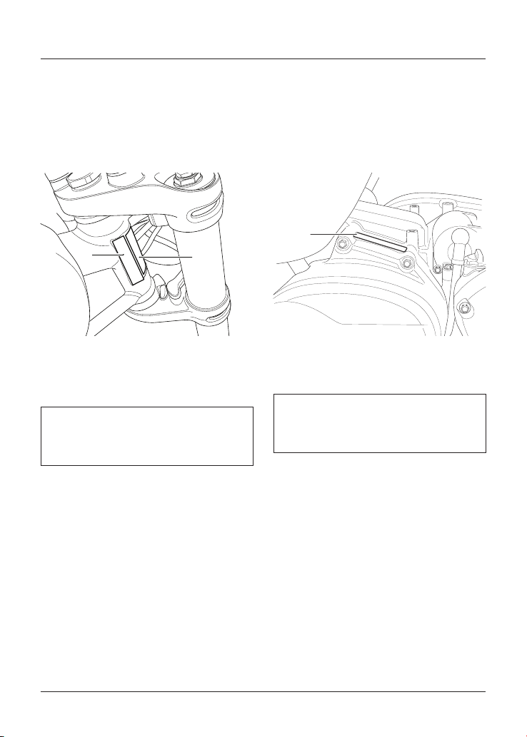
Serial Numbers
Vehicle Identification Number (VIN)
The vehicle identification number is
stamped into the steering head area of
the frame. It is also shown on a label
located next to it.
1
2
1. VIN stamp
2. VIN label
Record the vehicle identification number
in the space provided below.
Engine Serial Number
The engine serial number is stamped on
the upper engine crankcase, towards
the rear, and is visible from the right
hand side, behind the starter motor.
1
1. Engine serial number
Record the engine serial number in the
space provided below.

General Information
29
General Information
Table of Contents
Instrument Panel Layout 32
Warning Lights 34
Engine Management System Malfunction Indicator Light (MIL) 34
Low Oil Pressure Warning Light 34
High Coolant Temperature Warning Light 35
Engine Immobiliser/Alarm Indicator Light 35
Anti-lock Braking System (ABS) Warning Light 35
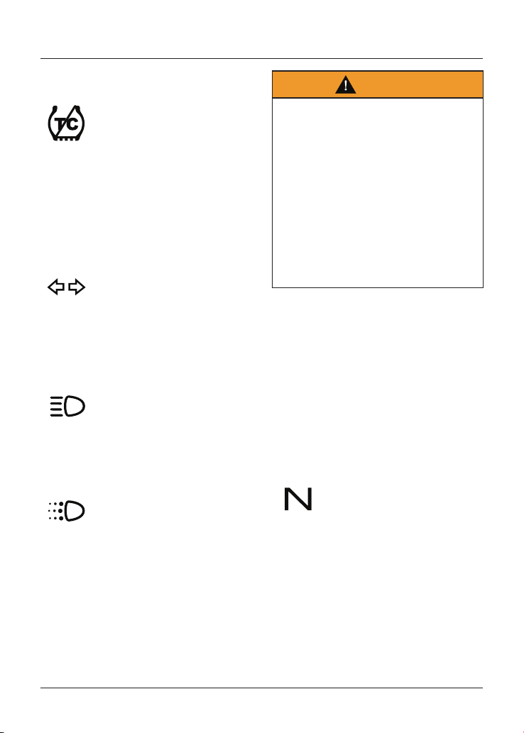
Traction Control (TC) Indicator Light 36
Traction Control (TC) Disabled Warning Light 37
Direction Indicators 37
High Beam 37
Daytime Running Lights (DRL) (if fitted) 37
Neutral 37
Low Fuel Indicator Light 38
Tyre Pressure Warning Light 38
General Warning Symbol 38
Instruments 39
Speedometer and Odometer 39
Tachometer 39
Gear Position Display 39
Fuel Gauge 40
Range to Empty 41
Average Fuel Consumption 42
Trip Meter 42
Clock 43
Riding Modes 44
Selecting a Riding Mode – with the Motorcycle Stationary 46
Selecting a Riding Mode – when Riding the Motorcycle 46
Traction Control (TC) 48
Traction Control Settings 48
To Disable the Traction Control 49
ABS Disable and Enable - Street Scrambler Models Only 50

General Information
30
Tyre Pressure Monitoring System (TPMS) (if fitted) 51
Tyre Pressure Sensor Serial Number 51
System Display 52
Sensor Batteries 52
Tyre Pressures 53
Replacement Tyres 53
Ignition Switch/Steering Lock 53
Engine Immobiliser 54
Ignition Key 54
Right Handlebar Switches 55
STOP Position 56
RUN Position 56
START Position 56
MODE Button (if fitted) 56
Hazard Warning Lights 56
Left Handlebar Switches 57
SCROLL Button 57
Horn Button 57
Direction Indicator Switch 57
MODE Button 57
Daytime Running Lights (DRL) Switch (if fitted) 57
High Beam Light 58
Heated Grips (if fitted) 58
Throttle Control 59
Clutch Lever Adjusters 60
Brake Lever Adjusters 61
Fuel 63
Fuel Tank Cap 64
Filling the Fuel Tank 65
Side Stand 66
Centre Stand (if fitted) 67
Side Panels 67
Tool Kit and Owner’s Handbook 69
Helmet Hook (if fitted) 70

General Information
32
Instrument Panel Layout
Street Scrambler and Street Twin (Street Twin shown)
10
20
30
40
50
60
70
80
90
100
110
120
130
0
0
20
40
60
80
100
120
140
160
180
200
19
18 17 16 15
11
10
9
8
7
5
4
3
2
1
12
14 13
20
6
MPH
km/h
1. Speedometer
2. Traction Control (TC) disabled warning
light
3. Traction Control (TC) indicator light
4. Low fuel level indicator light
5. High coolant temperature warning light
6. Low oil pressure warning light
7. Engine management Malfunction Indicator
Light (MIL)
8. Anti-lock Brake System (ABS) warning
light
9. Immobiliser/Alarm status indicator light
(alarm is an accessory kit)
10. Tyre pressure warning light (if Tyre
Pressure Monitoring System (TPMS) is
fitted)
11. Right hand direction indicator light
12. Neutral indicator light
13. Tachometer
14. Service interval indicator
15. Odometer/Trip meter/Clock
16. Rider mode display
17. Gear position indicator
18. Fuel gauge
19. High beam indicator light
20. Left hand direction indicator light
General Information
33
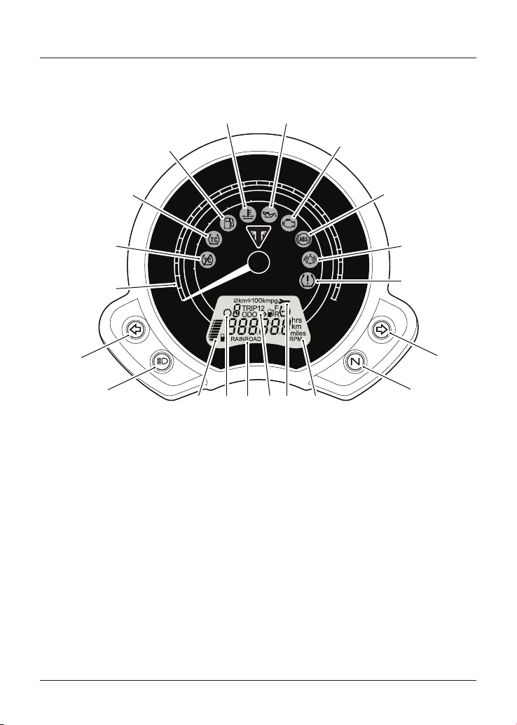
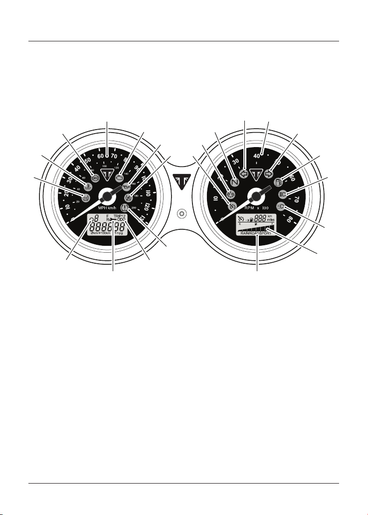
Instrument Panel Layout
Bonneville T100 (all models), Bonneville T120 (all models), Speed Twin and
Thruxton RS
1
2
3
4
5
6
78
9
11
12
13
14
15
16
18
20
22
10
21
19
17
1. Traction Control (TC) indicator light
2. High coolant temperature warning light
3. Anti-lock Brake System (ABS) warning
light
4. Speedometer
5. Engine management Malfunction Indicator
Light (MIL)
6. Low oil pressure warning light
7. Traction Control (TC) disabled warning
light
8. Cruise control indicator light (if fitted)
9. Immobiliser/Alarm indicator light (alarm is
an accessory kit)
10. Neutral indicator light
11. Left hand direction indicator light
12. Tachometer
13. Right hand direction indicator light
14. Low fuel level indicator light
15. High beam indicator light
16. Daytime Running Lights (DRL) indicator
light (if fitted)
17. Rider mode display (if fitted)
18. Range to empty display
19. Tyre pressure warning light (if Tyre
Pressure Monitoring System (TPMS) is
fitted)
20. Odometer/Trip computer
21. Service interval indicator
22. Gear position indicator
General Information
34
Warning Lights
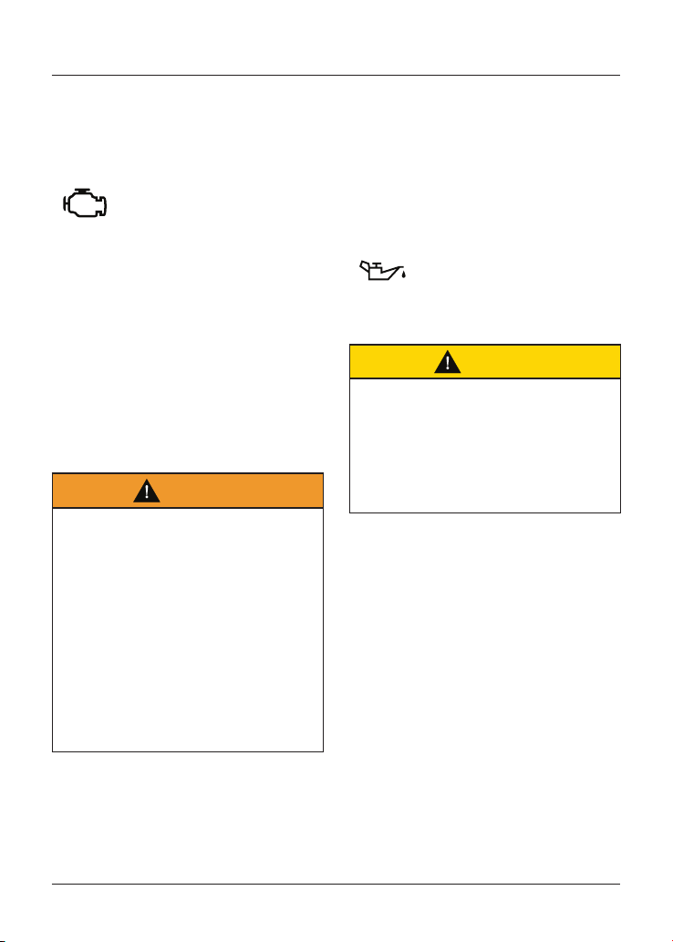
Engine Management System
Malfunction Indicator Light (MIL)
The Malfunction Indicator
Light (MIL) for the
engine management system
illuminates when the ignition
is switched ON (to indicate that it is
working) but should not become
illuminated when the engine is running.
If the engine is running and there is
a fault with the engine management
system the MIL will be illuminated and
the general warning symbol will flash.
In such circumstances, the engine
management system may switch to
'limp-home' mode so that the journey
may be completed, if the fault is not so
severe that the engine will not run.
Warning
Reduce speed and do not continue to
ride for longer than is necessary with
the MIL illuminated. The fault may
adversely affect engine performance,
exhaust emissions and fuel
consumption.
Reduced engine performance could
cause a dangerous riding condition,
leading to loss of control and an
accident.
Contact an authorised Triumph dealer
as soon as possible to have the fault
checked and rectified.
Note
If the MIL flashes when the ignition
is switched ON contact an authorised
Triumph dealer as soon as possible to
have the situation rectified. In these
circumstances the engine will not start.
Low Oil Pressure Warning Light
With the engine running,
if the engine oil pressure
becomes dangerously low, the
low oil pressure warning light
will illuminate.
Caution
Stop the engine immediately if the low
oil pressure warning light illuminates.
Do not restart the engine until the
fault has been rectified.
Severe engine damage will result from
running the engine when the low oil
pressure warning light is illuminated.
Note
The low oil pressure warning light will
illuminate if the ignition is switched ON
without running the engine.
General Information
35
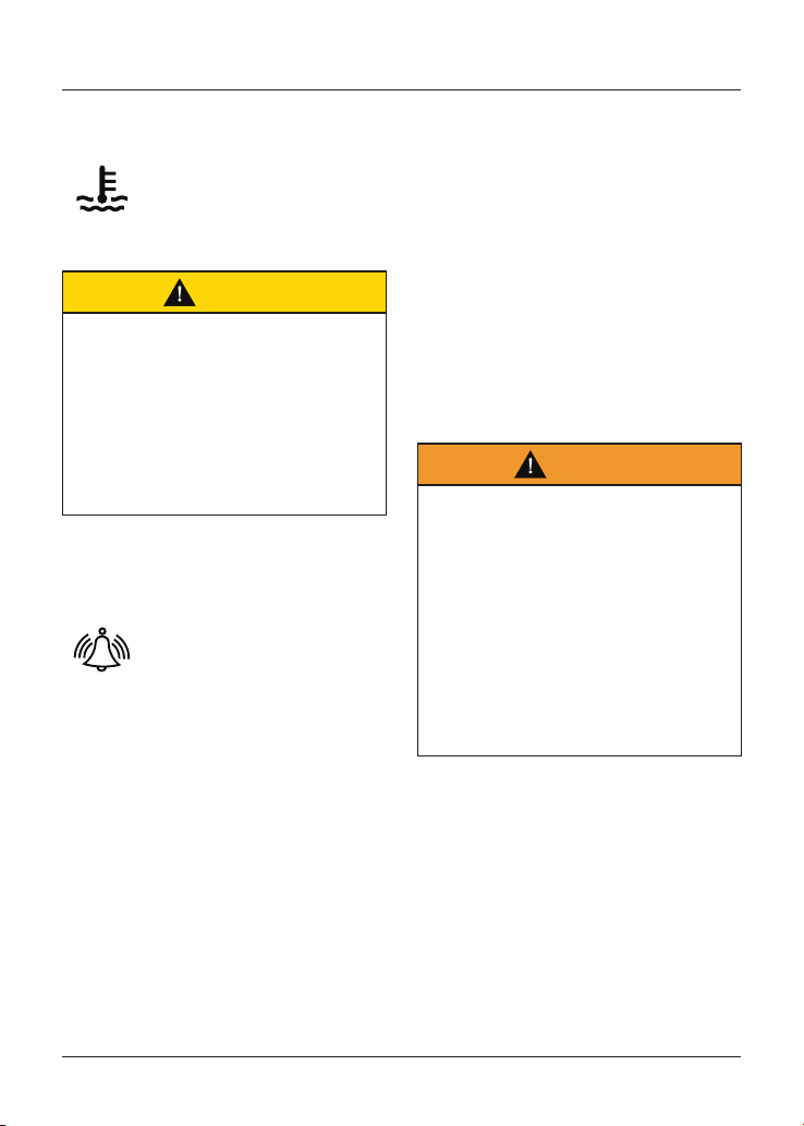
High Coolant Temperature Warning
Light
With the engine running,
if the engine coolant temp-
erature becomes dangerously
high, the high coolant
temperature warning light will illuminate.
Caution
Stop the engine immediately if the
high coolant temperature warning
light illuminates. Do not restart
the engine until the fault has been
rectified.
Severe engine damage will result from
running the engine when the high
coolant temperature warning light is
illuminated.
Engine Immobiliser/Alarm Indicator
Light
This Triumph motorcycle is
fitted with an engine
immobiliser which is activated
when the ignition switch is
turned to the OFF position.
Without Alarm Fitted
When the ignition switch is turned
to the OFF position, the engine
immobiliser/alarm light will flash on and
off for 24 hours to show that the engine
immobiliser is on. When the ignition
switch is turned to the ON position the
engine immobiliser and the indicator
light will be off.
If the indicator light remains on it
indicates that the engine immobiliser
has a malfunction that requires
investigation. Contact an authorised
Triumph dealer as soon as possible to
have the fault checked and rectified.
With Alarm Fitted
The engine immobiliser/alarm light will
only illuminate when the conditions
described in the genuine Triumph
accessory alarm instructions are met.
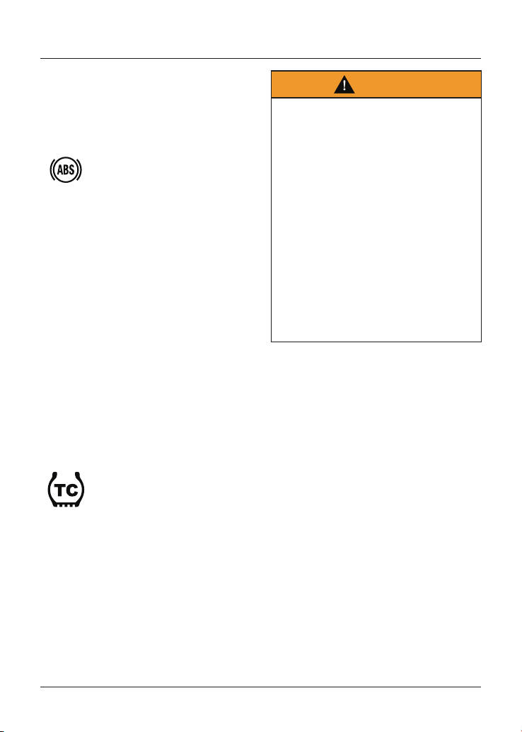
Anti-lock Braking System (ABS)
Warning Light
Warning
If the ABS is not functioning, the brake
system will continue to function as a
non-ABS equipped brake system.
Do not continue to ride for longer than
is necessary with the warning light
illuminated.
Contact an authorised Triumph dealer
as soon as possible to have the fault
checked and rectified. In this situation
braking too hard will cause the wheels
to lock resulting in loss of motorcycle
control and an accident.
General Information
36
Note
Traction control will not function if
there is a malfunction with the ABS.
The warning lights for the ABS, traction
control and the MIL will be illuminated.
When the ignition switch is
turned to the ON position, it is
normal that the ABS warning
light will flash on and off. The
light will continue to flash after engine
start-up until the motorcycle first
reaches a speed exceeding 6 mph
(10 km/h) when it will go off.
The warning light will not illuminate
again until the engine is restarted
unless there is a fault, or the ABS is
disabled by the rider (Street Scrambler
only).
If the ABS is disabled by the rider
(Street Scrambler only) then the
warning light will illuminate until the
ABS is enabled again.
If there is a fault with the ABS system
the warning light will be illuminated and
the general warning symbol will flash.
Traction Control (TC) Indicator Light
The Traction Control (TC)
indicator light is used to
indicate that the traction
control system is active and is
working to limit rear wheel slip during
periods of hard acceleration or under
wet or slippery road conditions.
Warning
If the traction control is not
functioning, care must be taken when
accelerating and cornering on wet/
slippery road surfaces to avoid rear
wheel spin.
Do not continue to ride for longer
than is necessary with the engine
management system Malfunction
Indicator Light (MIL) and traction
control warning lights illuminated.
Contact an authorised Triumph dealer
as soon as possible to have the fault
checked.
Hard acceleration and cornering in this
situation may cause the rear wheel
to spin resulting in loss of motorcycle
control and an accident.
If traction control is switched on:
• Under normal riding conditions the
TC indicator light will remain off.
• The TC indicator light will flash
rapidly when the traction control
system is working to limit rear
wheel slip during periods of hard
acceleration or under wet or
slippery road conditions.
If traction control is switched off:
• The TC indicator light will not
illuminate. Instead the TC disabled
warning light will be illuminated.
Note
Traction control will not function if there
is a malfunction with the ABS system.
The warning lights for the ABS, traction
control and the MIL will be illuminated.
General Information
37
Traction Control (TC) Disabled
Warning Light
The TC disabled warning light
should not illuminate unless
traction control is switched
off or there is a malfunction.
If the warning light becomes illuminated
at any other time while riding, it
indicates that the traction control
system has a malfunction that requires
investigation.
Direction Indicators
When the direction indicator
switch is turned to the left or
right, the direction indicator
warning light will flash on and
off at the same speed as the direction
indicators.
High Beam
When the ignition is switched
ON and the high beam is
selected, the high beam
warning light will illuminate.
Daytime Running Lights (DRL)
(if fitted)
When the ignition is switched
ON and the daytime running
lights switch is set to Daytime
Running Lights, the daytime
running lights warning light will
illuminate.
The daytime running lights and low
beam headlights are operated manually
using a switch on the left hand switch
housing, see page 37.
Warning
Do not ride for longer than necessary
in poor ambient light conditions with
the Daytime Running Lights (DRL) in
use.
Riding with the Daytime Running
Lights when dark, in tunnels or where
poor ambient light is apparent may
reduce the riders vision or dazzle
other road users.
Dazzling other road users or reduced
vision in low ambient light levels may
result in loss of motorcycle control and
an accident.
Note
During daylight hours the Daytime
Running Lights (DRL) improve the
motorcycles visibility to other road
users.
Low beam headlights must be used
in any other conditions unless the
road conditions allow for high beam
headlights to be used.
Neutral
The neutral warning light
indicates when the
transmission is in neutral (no
gear selected). The warning
light will illuminate when the
transmission is in neutral with the
ignition switch in the ON position.
General Information
38
Low Fuel Indicator Light
The low fuel indicator light will
illuminate when there are
approximately 3 litres of fuel
remaining in the tank.
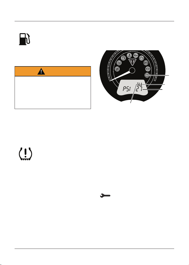
Tyre Pressure Warning Light
Warning
Stop the motorcycle if the tyre
pressure warning light illuminates.
Do not ride the motorcycle until the
tyres have been checked and the tyre
pressures are at their recommended
pressure when cold.
Note
Tyre Pressure Monitoring System
(TPMS) is an accessory option only
available on models fitted with cast alloy
wheels.
The tyre pressure warning
light works in conjunction
with the Tyre Pressure
Monitoring System (TPMS)
(see page 51).
The warning light will only illuminate
when the front or rear tyre pressure is
below the recommended pressure. It will
not illuminate if the tyre is over inflated.
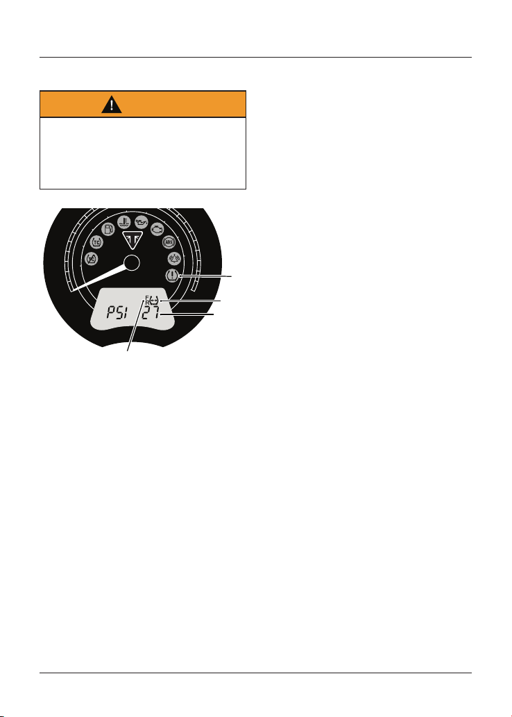
When the warning light is illuminated,
the TPMS symbol indicating which is
the deflated tyre and its pressure will
automatically be shown in the display
screen.
10
20
30
40
90
100
110
120
120
0
0
20
40
60
80
100
120
140
160
180
200
1
2
3
4
1. Tyre pressure warning light
2. TPMS symbol
3. Tyre pressure
4. Front and rear tyre indicators
The tyre pressure at which the warning
light illuminates is temperature
compensated to 20°C but the numeric
pressure display associated with it
is not. Even if the numeric display
seems at or close to the standard tyre
pressure when the warning light is on,
a low tyre pressure is indicated and a
puncture is the most likely cause.
General Warning Symbol
The general warning symbol will
flash if an ABS or engine
management fault has occurred
and the ABS and/or MIL warning lights
are illuminated. Contact an authorised
Triumph dealer as soon as possible to
have the fault checked and rectified.
General Information
39
Instruments
Speedometer and Odometer
The speedometer indicates the road
speed of the motorcycle.
The odometer shows the total distance
that the motorcycle has travelled.
Tachometer
Caution
Never allow engine speed to enter the
red zone as severe engine damage
may result.
The tachometer shows the engine
speed in revolutions per minute - rpm
(r/min). At the end of the tachometer
range there is the red zone.
Engine speeds in the red zone are above
maximum recommended engine speed
and are also above the range for best
performance.
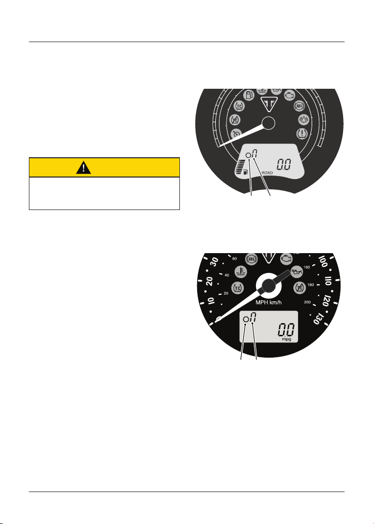
Gear Position Display
Street Scrambler and Street Twin
Only
10
20
30
100
110
120
120
0
0
20
40
60
0
160
180
200
1
2
1. Gear position symbol
2. Gear position display (neutral position
shown)
All Other Models
21
1. Gear position symbol
2. Gear position display (neutral position
shown)
The gear position display indicates
which gear (1-5 or 1-6) has been
engaged. When the transmission is in
neutral (no gear selected), the display
screen will show 'n'.
General Information
40
Fuel Gauge
Street Scrambler and Street Twin
Only
10
20
30
40
90
100
110
120
120
0
0
20
40
60
80
120
140
160
180
200
21
1. Low fuel indicator light
2. Fuel gauge
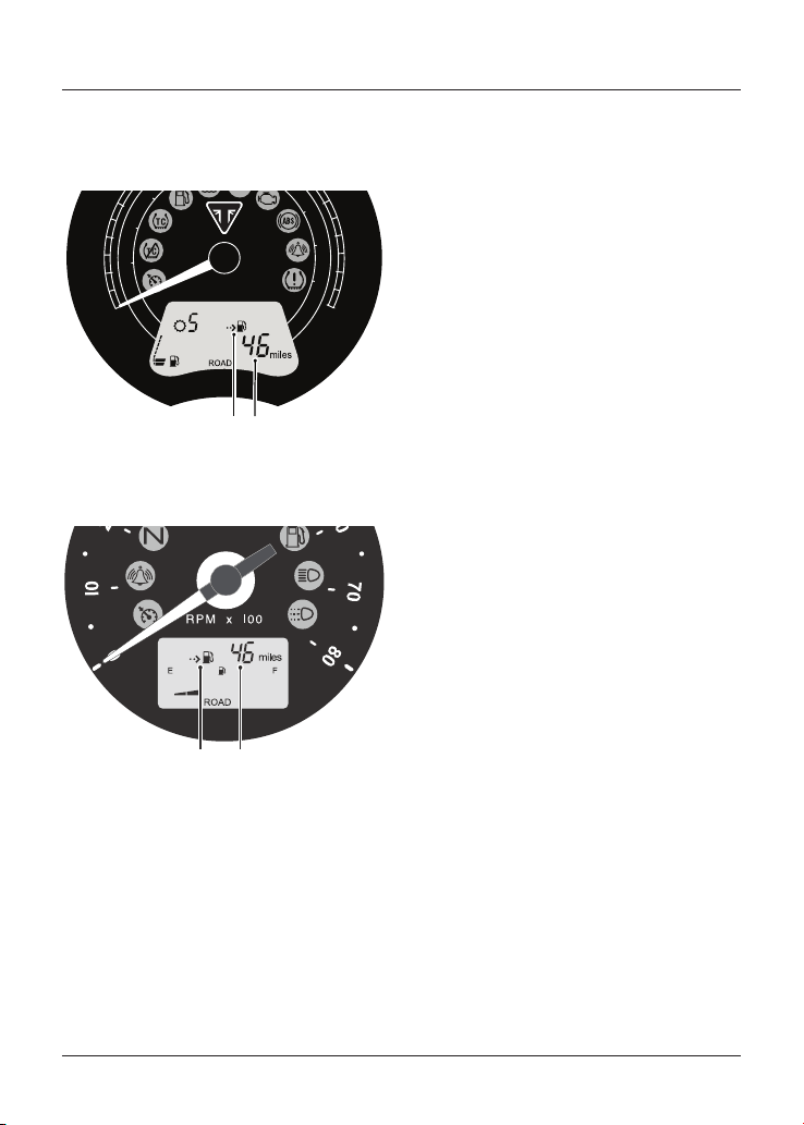
All Other Models
1
2
1. Fuel gauge
2. Low fuel indicator light
The fuel gauge indicates the amount
of fuel in the tank. With the ignition
switched on, the number of bars shown
in the display indicates the level of fuel.
When the fuel tank is full all eight bars
are displayed and when empty, no bars
are displayed. Other gauge markings
indicate intermediate fuel levels
between full and empty.
When there are approximately 3 litres of
fuel remaining in the tank, the low fuel
warning light will illuminate.
Note
After refuelling, the fuel gauge and
range to empty information will
be updated only while riding the
motorcycle. Depending on the riding
style, updating could take up to five
minutes.
General Information
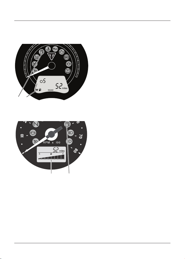
41
Range to Empty
Street Scrambler and Street Twin
Only
10
20
30
00
110
120
120
0
0
20
40
60
160
180
200
21
1. Range to empty indicator
2. Estimated distance remaining
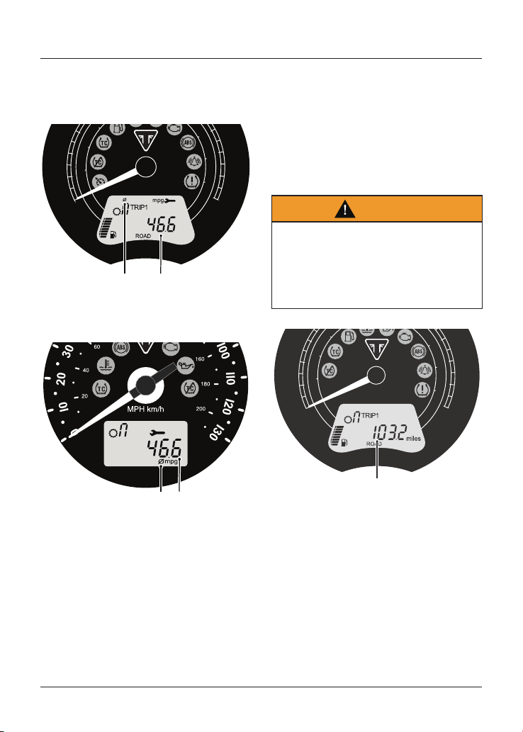
All Other Models
21
1. Range to empty indicator
2. Estimated distance remaining
This is an indication of the predicted
distance that can be travelled on the
remaining fuel in the tank.
Note
After refuelling, the fuel gauge and
range to empty information will
be updated only while riding the
motorcycle. Depending on the riding
style, updating could take up to five
minutes.
General Information
42
Average Fuel Consumption
Street Scrambler and Street Twin
Only
10
20
30
00
110
120
120
0
0
20
40
60
160
180
200
21
1. Average symbol
2. Average fuel consumption
All Other Models
21
1. Average symbol
2. Average fuel consumption
This is an indication of the average
fuel consumption. After being reset the
display will show dashes until 0.1 miles/
km has been covered.
Note
After refuelling, the average
consumption information will be updated
only while riding the motorcycle.
Depending on the riding style, updating
could take up to five minutes.
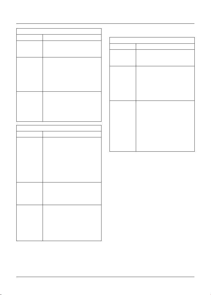
Trip Meter
Warning
Do not attempt to switch between
the odometer and trip meter display
modes or reset the trip meter with the
motorcycle in motion as this may lead
to loss of motorcycle control and an
accident.
10
20
30
100
110
120
120
0
0
20
40
60
0
160
180
200
1
1. Trip meter display (Trip 1 selected)
There are two trip meters. Either trip
meter shows the distance that the
motorcycle has travelled since the
meter on display was last reset to zero.
General Information
43
To switch between trip meters, press
and release the SCROLL button, located
on the left hand handlebar switch
housing, until the required trip meter is
shown.
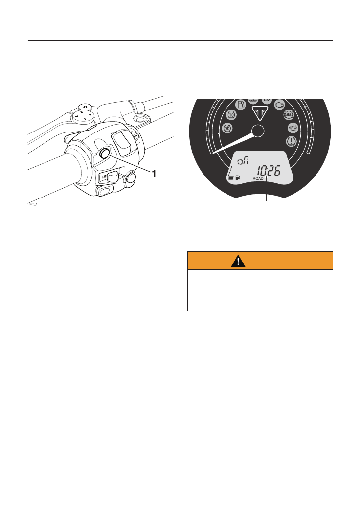
1
cixb_1
1. SCROLL button
Note
Street Scrambler Only
The trip meters are not accessible when
in OFF ROAD mode. The trip meter data
continues to be collected when riding in
OFF ROAD mode. The updated trip meter
data is shown in the trip meters after
switching the OFF ROAD mode off.
Trip Meter Reset
To reset either of the trip meters:
• Select the trip meter to be zeroed.
• Press and hold the SCROLL button
for one second. After more than one
second, the trip meter on display will
reset to zero.
Clock
To access the clock, press and release
the SCROLL button, located on the left
hand handlebar switch housing, until
the clock is shown.
10
20
30
100
110
120
120
0
0
20
40
60
0
160
180
200
1
1. Clock
Clock Adjustment
Warning
Do not attempt to adjust the clock
with the motorcycle in motion as this
may lead to loss of motorcycle control
and an accident.
To reset the clock:
• Select the clock display.
• Press and hold the SCROLL button
for one second, the clock’s hour
display will start to flash. Release
the SCROLL button.

General Information
44
To reset the hour display:
• Make sure the hour display is still
flashing then press and release
the SCROLL button to change the
setting. Each individual button press
will change the setting by one digit.
• When the correct hour display is
shown, press and hold the SCROLL
button for one second. The hours
display is set and the minutes
display will begin to flash. The
minutes display is adjusted in the
same way as for the hour display.
• Once both hours and minutes are
correctly set, press the SCROLL
button for one second and the
display will cease to flash.
Riding Modes
Note
Riding modes are available on all
models except Bonneville T100 and
Bonneville T100 Bud Ekins.
The riding mode system allows the
selection of riding modes with specific
traction control and throttle response
settings.
Riding modes are selected using the
MODE button on either the left or
right hand handlebar switch housing,
depending on the model.
Press and release the MODE button to
select one of the following riding modes.
Bonneville T120 (all models) and Street Twin
Riding Mode Description
ROAD
Standard throttle response.
Optimal traction control setting
for road use.
RAIN
Reduced throttle response when
compared to the ROAD setting,
for wet or slippery conditions.
Optimal traction control setting
for road use in rain conditions
and allows minimal rear wheel
slip.
General Information
45
Speed Twin
Riding Mode Description
ROAD
Standard throttle response.
Optimal traction control setting
for road use.
RAIN
Reduced throttle response when
compared to the ROAD setting,
for wet or slippery conditions.
Optimal traction control setting
for road use in rain conditions
and allows minimal rear wheel
slip.
SPORT
Increased throttle response
when compared to the ROAD
setting.
Optimal traction control setting
for road use and allows minimal
rear wheel slip.
Thruxton RS
Riding Mode Description
RAIN
Reduced throttle response when
compared to the ROAD setting,
for wet or slippery conditions.
Optimal ABS setting for road use.
Optimal traction control setting
for wet and slippery conditions.
Allows reduced rear wheel slip
when compared with the ROAD
setting.
ROAD
Standard throttle response.
Optimal ABS setting for road use.
Optimal traction control setting
for road use.
SPORT
Increased throttle response
when compared to the ROAD
setting.
Optimal ABS setting for road use.
Allows increased rear wheel slip
when compared with the ROAD
setting.
Street Scrambler Only
Street Scrambler
Riding Mode Description
ROAD
Standard throttle response.
Optimal traction control setting
for road use.
RAIN
Reduced throttle response when
compared to the ROAD setting,
for wet or slippery conditions.
Optimal traction control setting
for road use in rain conditions
and allows minimal rear wheel
slip.
OFF ROAD
Optimal throttle response setting
for off-road use.
ABS is off. Traction control is off.
Trip meters are not shown. Trip
meter data continues to be
collected when riding in this
mode.
OFF ROAD mode can only be
selected when the motorcycle is
stationary.
General Information
46
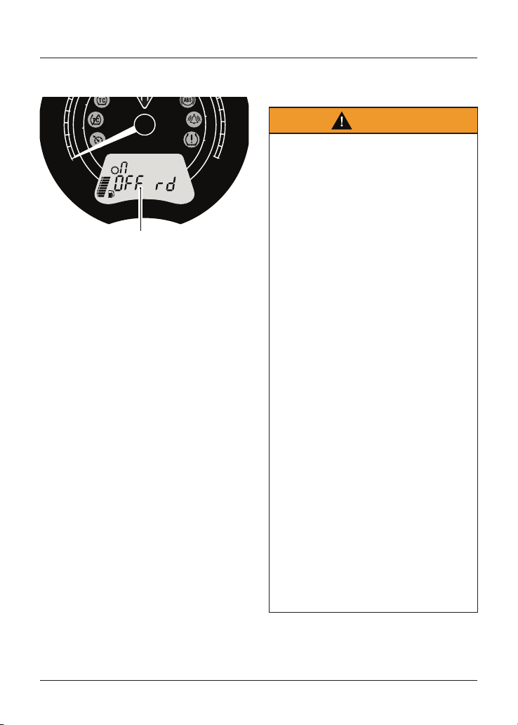
If OFF ROAD mode is selected, it is
shown in the main display.
10
20
110
120
120
0
0
20
40
0
180
200
1
1. OFF ROAD mode display (Street Scrambler
only)
When in OFF ROAD mode, a long press
on the MODE button changes the riding
mode to ROAD mode.
Selecting a Riding Mode – with the
Motorcycle Stationary
Press and release the MODE button on
either the left or right hand handlebar
switch housing (model specific) until the
required riding mode is flashing in the
display.
The selected riding mode is
automatically activated one second
after the MODE button is pressed, if the
following conditions are met:
With the Engine Off
• The ignition is switched ON.
• The engine stop switch is in the
RUN position.
With the Engine Running
• The transmission is in neutral or the
clutch is pulled in.
Selecting a Riding Mode – when
Riding the Motorcycle
Warning
The selection of riding modes whilst
the motorcycle is in motion requires
the rider to allow the motorcycle to
coast (motorcycle moving, engine
running, throttle closed, clutch lever
pulled in and no brakes applied) for a
brief period of time.
Riding mode selection whilst the
motorcycle is in motion should only be
attempted:
- At low speed
- In traffic free areas
- On straight and level roads or
surfaces
- In good road and weather conditions
- Where it is safe to allow the
motorcycle to briefly coast.
Riding mode selection whilst the
motorcycle is in motion MUST NOT be
attempted:
- At high speeds
- Whilst riding in traffic
- During cornering or on winding roads
or surfaces
- On steeply inclined roads or surfaces
- In poor road/weather conditions
- Where it is unsafe to allow the
motorcycle to coast.
Failure to observe this important
warning will lead to loss of motorcycle
control and an accident.
General Information
47
Warning
After selecting a riding mode, operate
the motorcycle in an area free from
traffic to gain familiarity with the new
settings.
Do not loan your motorcycle to anyone
as they may change the riding mode
setting from the one you are familiar
with, causing loss of motorcycle
control and an accident.
Note
Street Scrambler Only
OFF ROAD mode is not available to select
when riding the motorcycle. It can only
be selected when the motorcycle is
stationary.
OFF ROAD mode can be switched off by
a long press on the MODE button which
then selects ROAD mode.
Press and release the MODE button on
either the left or right hand handlebar
switch housing (model specific) until the
required riding mode is flashing in the
display.
Within 30 seconds of pressing the
MODE button the rider must carry out
the following simultaneously:
• Close the throttle.
• Pull the clutch in.
• Make sure that the brakes are not
engaged (allow the motorcycle to
coast).
Note
The last riding mode selected before the
ignition is switched OFF will be the same
riding mode active when the ignition is
switched ON again.
In the event of an incomplete riding
mode change:
• Safely bring the motorcycle to a
stop.
• Select neutral gear.
• Turn the ignition OFF and then back
ON again.
• Select the required riding mode.
• Restart the engine and continue
riding.
Warning
Do not stop the engine using the
ignition switch or engine start/stop
switch whilst the motorcycle is moving.
Always bring the motorcycle to a stop
safely and engage neutral gear prior
to stopping the engine.
Stopping the engine by turning off the
ignition or engine start/stop switch
whilst the motorcycle is moving can
lock the rear wheel causing loss of
motorcycle control and an accident.
Caution
Do not stop the engine using the
ignition switch or engine start/stop
switch whilst the motorcycle is moving.
Stopping the engine by turning off
the ignition or engine start/stop
switch when the motorcycle is moving
may cause damage to motorcycle
components.
General Information
48
Traction Control (TC)
Warning
Traction control is not a substitute for
riding appropriately for the prevailing
road and weather conditions.
The traction control cannot prevent
loss of traction due to:
- Excessive speed when entering turns
- Accelerating at a sharp lean angle
- Braking
- Traction control cannot prevent the
front wheel from slipping.
Failure to observe any of the above
may result in loss of motorcycle
control and an accident.
Traction control helps to maintain
traction when accelerating on wet/
slippery road surfaces. If sensors detect
that the rear wheel is losing traction
(slipping), the traction control system
will engage and alter the engine power
until traction to the rear wheel has been
restored. The traction control warning
light will flash while it is engaged and
the rider may notice a change to the
sound of the engine.
Note
Traction control will not function if there
is a malfunction with the ABS system.
The warning lights for the ABS, traction
control and the MIL will be illuminated.
Note
Street Scrambler Only
Traction control is switched off when in
OFF ROAD mode.
Traction Control Settings
Warning
Do not attempt to adjust the traction
control settings while the motorcycle
is in motion as this may lead to loss of
motorcycle control and an accident.
Warning
If the traction control is disabled,
the motorcycle will handle as normal
but without traction control. In this
situation accelerating too hard on
wet/slippery road surfaces may cause
the rear wheel to slip, and may result
in loss of motorcycle control and an
accident.
The traction control can be set to one of
the following conditions:
ON
Optimal traction control setting
for road use, allows minimal rear
wheel slip.
OFF
Traction control is turned OFF.
The TC disabled warning light
will be illuminated (see page 37).
Traction control defaults to ON after
the ignition has been switched OFF and
then switched ON again.
General Information
49
To Disable the Traction Control
Warning
After riding off-road with traction
control disabled, always make sure
that the traction control is enabled
when returning to ride on public roads.
Riding on public roads with the
traction control disabled may, if
accelerating too hard on wet/slippery
road surfaces, cause the rear wheel
to slip resulting in loss of motorcycle
control and an accident.
To disable the traction control setting:
• Make sure the motorcycle is
stationary and in neutral.
• Turn the ignition to the ON position
and put the engine start/stop
switch in the RUN position.
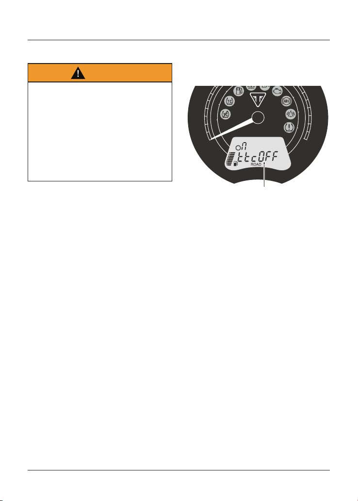
• Press and release the SCROLL
button on the left hand handlebar
switch housing until ’ttcOn’ is shown
in the display.
• Press and hold the SCROLL button
for more than one second to change
between traction control on and
traction control off.
10
20
30
100
110
120
120
0
0
20
40
60
0
160
180
200
1
1. Traction control off display (Street Twin
shown)
General Information
50
ABS Disable and Enable -
Street Scrambler Models Only
Warning
Do not attempt to adjust the ABS
settings while the motorcycle is in
motion as this may lead to loss of
motorcycle control and an accident.
Warning
If the ABS is disabled, the brake
system will function as a non-ABS
braking system. In this situation
braking too hard will cause the wheels
to lock, and may result in loss of
motorcycle control and an accident.
Warning
After riding off-road with ABS
disabled, always make sure that the
ABS is enabled when returning to ride
on public roads.
Riding on public roads with the ABS
disabled will, if braking too hard, cause
the wheels to lock resulting in loss of
motorcycle control and an accident.
ABS Disable
It is possible to temporarily disable the
ABS. The ABS cannot be permanently
disabled, it will be enabled when the
ignition is turned off and then on again.
To disable the ABS:
• Make sure the motorcycle is
stationary and in neutral. Turn the
ignition to the ON position and put
the engine start/stop switch in the
RUN position.
• Press and release the SCROLL
button until ’AbSOn’ is shown in the
left hand display.
• Press and hold the SCROLL button
for one second to change between
ABS on and ABS off.
• The display shows ‘AbSOFF’ when
the ABS is disabled, and the ABS
warning light will be illuminated.
Note
With the ABS disabled, the traction
control will still function (unless traction
control has been manually disabled).
ABS Enable
To enable the ABS, do one of the
following:
• Repeat the ABS disable procedure
and select 'AbSOn'.
• Turn the ignition OFF and then ON.
• The ABS will be enabled when
the motorcycle reaches a speed
exceeding 6 mph (10 km/h). The ABS
warning light will turn off.
General Information
51
Tyre Pressure Monitoring
System (TPMS) (if fitted)
Warning
The daily check of tyre pressures
must not be excluded because of the
fitment of the TPMS. Check the tyre
pressure when the tyres are cold
using an accurate tyre pressure gauge
(see page 135).
Use of the TPMS system to set
inflation pressures may lead to
incorrect tyre pressures leading to
loss of motorcycle control and an
accident.
Note
Tyre Pressure Monitoring System
(TPMS) is an accessory option only
available on models fitted with cast alloy
wheels.
Function
Tyre pressure sensors are fitted to the
front and rear wheels. These sensors
measure the air pressure inside the
tyre and transmit pressure data to the
instruments. These sensors will not
transmit the data until the motorcycle
is travelling at a speed greater than
12 mph (20 km). Two dashes will be
shown in the display screen until the
tyre pressure signal is received.
The Tyre Pressure Monitoring System
(TPMS) is an accessory fitted item and
must be fitted by your authorised
Triumph dealer.
The TPMS display screen on the
instruments will only be activated when
the system has been fitted.
An adhesive label will be fitted to the
wheel rim to indicate the position of the
tyre pressure sensor which is near the
valve.
Tyre Pressure Sensor Serial Number
The serial number for the tyre pressure
sensor is printed on a label attached
to the sensor. This number may be
required by your authorised Triumph
dealer for service or diagnostics.
When the tyre pressure monitoring
system is being fitted to the motorcycle,
make sure that your authorised Triumph
dealer records the serial numbers of the
front and rear tyre pressure sensors in
the spaces provided below.
Front Tyre Pressure Sensor
Rear Tyre Pressure Sensor
General Information
52
System Display
Warning
Do not attempt to switch between
front and rear tyre display modes with
the motorcycle in motion as this may
lead to loss of motorcycle control and
an accident.
10
20
30
40
90
100
110
120
120
0
0
20
40
60
80
100
120
140
160
180
200
1
2
3
4
1. TPMS warning light
2. TPMS symbol
3. Tyre pressure
4. Front and rear tyre indicators
To view the tyre pressure display:
• Make sure the motorcycle is
stationary and in neutral. Turn the
ignition to the ON position.
• Press and release the SCROLL
button until PSI or bAr is shown in
the display screen.
• Press and hold the SCROLL button
for one second to change between
PSI and bar.
• Once PSI or bar has been selected,
press and release the SCROLL
button to select the front or rear
tyre pressure.
• When the tyre pressure monitoring
system has been selected, —— PSI
or bAr is shown in display screen
until the motorcycle is travelling at a
speed greater than 12 mph (20 km/h)
and the tyre pressure signal is
received.
• To exit the tyre pressure display,
press and release the SCROLL
button until the desired display
screen is shown.
Sensor Batteries
When the battery voltage in a pressure
sensor is low, LO bAt will be displayed
and the TPMS symbol will indicate
which wheel sensor has the low battery
voltage. If the batteries are completely
flat, only dashes will be visible in the
display screen, the red TPMS warning
light will be on and the TPMS symbol
will flash continuously. Contact your
authorised Triumph dealer to have the
sensor replaced and the new serial
number recorded in the spaces provided
on page 51.
With the ignition switch turned to the
ON position, if the TPMS symbol flashes
for 10 seconds and then remains on
there is a fault with the TPMS system.
Contact your authorised Triumph dealer
to have the fault rectified.
General Information
53
Tyre Pressures
Warning
The Tyre Pressure Monitoring System
(TPMS) is not to be used as a tyre
pressure gauge when adjusting the
tyre pressures.
For correct tyre pressures, always
check the tyre pressures when the
tyres are cold using an accurate tyre
pressure gauge.
Use of the TPMS system to set
inflation pressures may lead to
incorrect tyre pressures leading to
loss of motorcycle control and an
accident.
The tyre pressures shown on your
instrument panel indicate the actual
tyre pressure at the time of selecting
the display. This may differ from the
inflation pressure set when the tyres
are cold because tyres become warmer
during riding, causing the air in the tyre
to expand and the inflation pressure to
increase. The cold inflation pressures
specified by Triumph take account of
this.
Only adjust tyre pressures when the
tyres are cold using an accurate tyre
pressure gauge (see page 135). Do not
use the tyre pressure display on the
instruments.
Replacement Tyres
When replacing tyres, always have an
authorised Triumph dealer fit your tyres
and make sure they are aware that
tyre pressure sensors are fitted to the
wheels.
Ignition Switch/Steering Lock
Warning
For reasons of security and safety,
always turn the ignition to the OFF
or PARK position and remove the
key when leaving the motorcycle
unattended.
Any unauthorised use of the
motorcycle may cause injury to
the user, other road users and
pedestrians and may also cause
damage to the motorcycle.
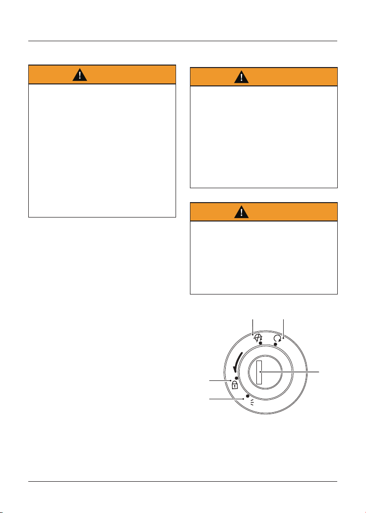
Warning
With the key in the LOCK or P position,
the steering will become locked.
Never turn the key to the LOCK or
P positions while the motorcycle is
moving as this will cause the steering
to lock. Locked steering will cause loss
of motorcycle control and an accident.
P
U
S
H
P
O
F
F
O
N
3
2
1
5
4
1. PARK position
2. LOCK position
3. OFF position
4. ON position
5. Ignition switch/Steering lock
General Information
54
Switch Operation
This is a four position, key operated
switch. The key can be removed from
the switch only when it is in the OFF,
LOCK or P (PARK) position.
TO LOCK: Turn the steering fully to the
left, turn the key to the OFF position,
push and fully release the key, then
rotate it to the LOCK position.
PARKING: Turn the key from the LOCK
position to the P position. The steering
will remain locked.
Note
Do not leave the steering lock in the P
position for long periods of time as this
will cause the battery to discharge.
Engine Immobiliser
The ignition switch housing acts as the
antenna for the engine immobiliser.
When the ignition switch is turned to
the OFF position and the ignition key is
removed, the engine immobiliser is on
(see page 35). The engine immobiliser is
turned off when the ignition key is in
the ignition switch and it is turned to
the ON position.
Ignition Key
Warning
Additional keys, key rings/chains or
items attached to the ignition key may
interfere with the steering, leading
to loss of motorcycle control and an
accident.
Remove all additional keys, key rings/
chains and items from the ignition key
before riding the motorcycle.
Caution
Additional keys, key rings/chains or
items attached to the ignition key may
cause damage to the motorcycle's
painted or polished components.
Remove all additional keys, key rings/
chains and items from the ignition key
before riding the motorcycle.
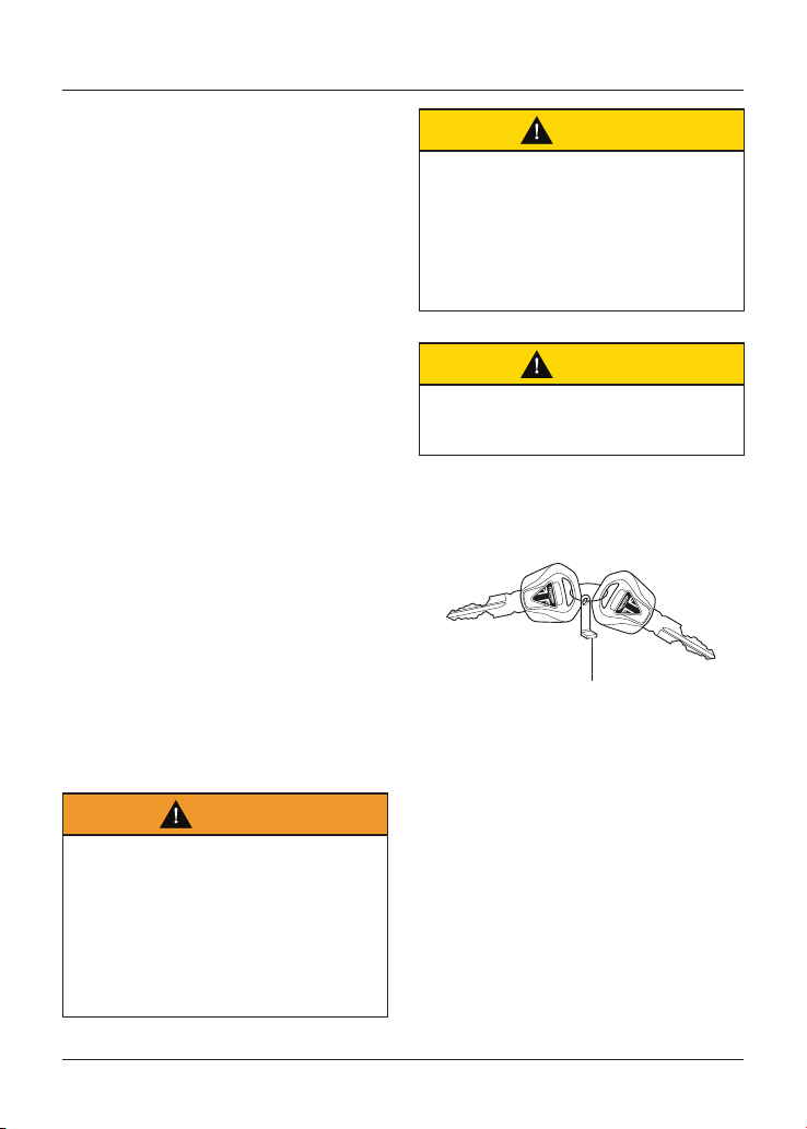
Caution
Do not store the spare key with the
motorcycle as this will reduce all
aspects of security.
1
1. Key number tag
In addition to operating the ignition
switch/steering lock, the ignition key is
required to operate the seat lock and
fuel tank cap.
When the motorcycle is delivered
from the factory, two ignition keys
are supplied together with a small tag
bearing the key number. Make a note
of the key number and store the spare
key and key number tag in a safe place
away from the motorcycle.
General Information
55
A transponder is fitted within the
ignition keys to turn off the engine
immobiliser. To make sure the
immobiliser functions correctly, always
have only one of the ignition keys near
the ignition switch. Having two ignition
keys near the switch may interrupt the
signal between the transponder and
the engine immobiliser. In this situation
the engine immobiliser will remain active
until one of the ignition keys is removed.
Always get replacement keys from
your authorised Triumph dealer.
Replacement keys must be 'paired' with
the motorcycle’s immobiliser by your
authorised Triumph dealer.
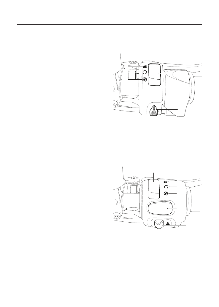
Right Handlebar Switches
Speed Twin, Street Scrambler,
Street Twin and Thruxton RS
1
5
4
3
2
1. Engine start/stop switch
2. STOP position
3. RUN position
4. START position
5. Hazard warning light switch
Bonneville T100 (all models) and
Bonneville T120 (all models)
1
5
4
3
2
6
1. Engine start/stop switch
2. STOP position
3. RUN position
4. START position
5. MODE button (Bonneville T120 (all models)
only)
6. Hazard warning light switch
General Information
56
STOP Position
The STOP position is for emergency use.
If an emergency arises which requires
the engine to be stopped, move the
engine start/stop switch to the STOP
position.
Caution
Do not leave the ignition switch in
the ON position unless the engine is
running as this may cause damage
to electrical components and will
discharge the battery.
Note
Although the engine stop switch stops
the engine, it does not turn off all
the electrical circuits and may cause
difficulty in restarting the engine due
to a discharged battery. Ordinarily, only
the ignition switch should be used to
stop the engine.
RUN Position
In addition to the ignition switch being
turned to the ON position, the engine
start/stop switch must be in the RUN
position for the motorcycle to operate.
START Position
The START position operates the electric
starter. For the starter to operate,
the clutch lever must be pulled to the
handlebar.
Note
Even if the clutch lever is pulled to the
handlebar, the starter will not operate
if the side stand is down and a gear is
engaged.
MODE Button (if fitted)
The MODE button allows throttle
response adjustment. Press and release
the MODE button to select one of the
different rider modes available (see
page 44 for more information).
Hazard Warning Lights
To turn the hazard warning lights on
or off, press and release the hazard
warning light switch.
The ignition must be switched ON for
the hazard warning lights to function.
The hazard warning lights will remain on
if the ignition is switched off, until the
hazard warning light switch is pressed
again.
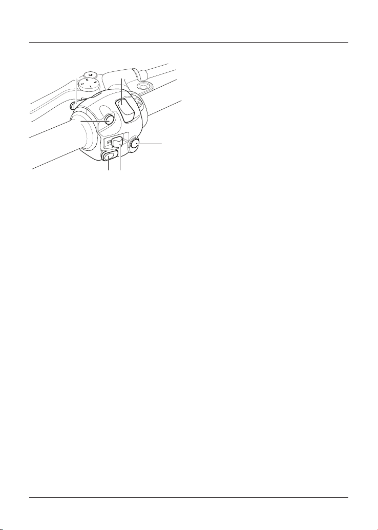
General Information
57
Left Handlebar Switches
1
23
4
5
6
1. SCROLL button
2. Horn button
3. Direction indicator switch
4. MODE button (Speed Twin,
Street Scrambler, Street Twin and
Thruxton RS only)
5. Daytime Running Lights (DRL) switch
(if fitted)
6. High beam button
SCROLL Button
The SCROLL button is used to
operate the following functions of the
instruments:
• Odometer functions (see page 42)
• Trip reset (see page 42)
• Clock reset (see page 43)
• Traction control functions (see
page 48).
Horn Button
When the horn button is pushed, with
the ignition switch turned on, the horn
will sound.
Direction Indicator Switch
When the direction indicator switch
is pushed to the left or right, the
corresponding direction indicators will
flash on and off.
The indicators can be cancelled
manually. To manually turn off the
indicators, press and release the
indicator switch in the central position.
MODE Button
The MODE button allows throttle
response adjustment. Press and release
the MODE button to select one of the
different rider modes available (see
page 44 for more information).
Daytime Running Lights (DRL)
Switch (if fitted)
Note
Daytime running lights are manually
operated. They are not automatic.
The daytime running lights or dip
beam can be selected with the Daytime
Running Lights (DRL) switch.
To select daytime running lights, push
the DRL switch forward.
To select dip beam, push the DRL switch
rearwards.
When the daytime running lights are
turned on, the daytime running lights
indicator light will illuminate in the
instrument panel.
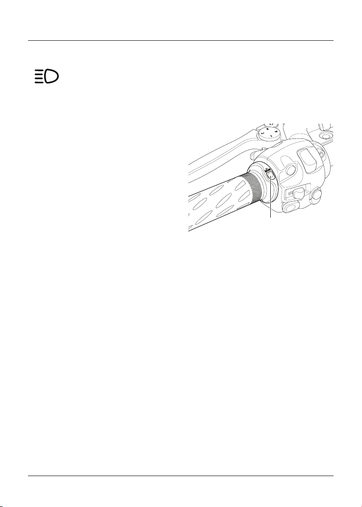
General Information
58
High Beam Light
When the high beam button is
pressed the high beam will be
switched on. Each press of
the button will swap between
dip and high beam.
Note
If daytime running lights are fitted to
the motorcycle, the high beam button
has additional functionality.
If the DRL switch is in the daytime
running lights position, then press and
hold the high beam button to turn the
high beam on. It will remain on as long
as the button is held in and will turn off
as soon as the button is released.
Note
A lighting on/off switch is not fitted to
this model. The rear light and licence
plate light all function automatically
when the ignition is on.
The headlight will function when the
ignition is on. The headlight will go off
while pressing the starter button until
the engine starts.
Heated Grips (if fitted)
The heated grips work when the
ignition is switched on. However, it is
recommended that they are only used
when the engine is running to avoid
draining the battery.
There are two heat levels; low or high.
1
1. Heated grips button
The heated grips button is located on
the left hand grip.
Press the heated grip button to show
the current status of the heated grips
in the display screen. This is shown for
three seconds.
Press the heated grip button whilst the
status is showing to select one of the
three different heat levels; OFF, Lo (low)
or HI (high).
For maximum benefit in cold conditions,
use the heated grips on the HI level
initially and when the grips have
warmed up, change to Lo.
To switch off the heated grips, press
and release the button until OFF is
shown in the display screen. The heated
grips are also switched off when the
ignition is switched off.
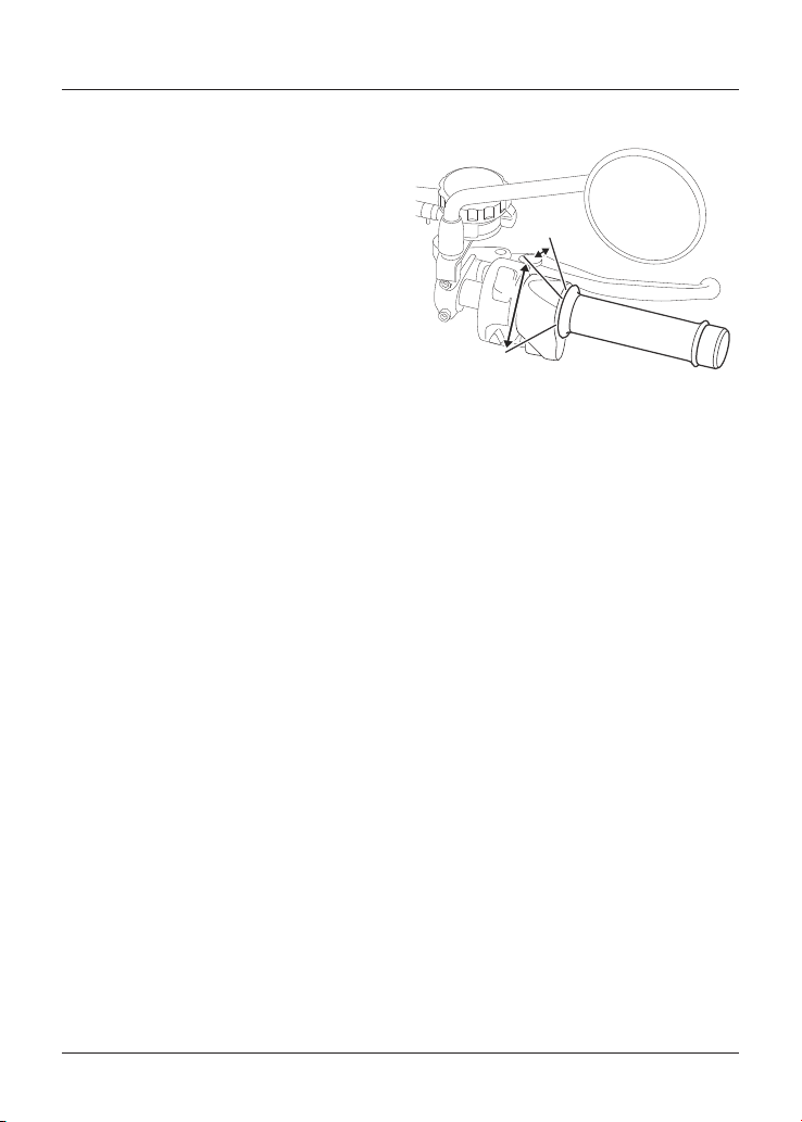
General Information
59
Low Battery Warning
If heated grips are fitted and are on
with the engine not running, over a
period of time, the battery voltage may
drop below 11.8 Volts and ‘LoBAtt’ is
then shown in the display screen for
three seconds.
If the heated grips are on and ‘LoBAtt’
is shown, then the heated grips are
automatically switched off to prevent
further discharge of the battery. It is
not possible to resume heated grip
operation until the engine has been
running and the battery voltage has
increased above 11.8 Volts.
In the event of a fault, ‘HgrOFF’ is
shown in the display screen and the
heated grips are automatically switched
off. The heated grips can be switched
back on by:
• waiting 25 seconds then switch on
the heated grip, or
• turning the ignition switch to the
OFF position then back to the ON
position.
If ‘HgrOFF’ remains shown in the display
screen, then contact an authorised
Triumph dealer to have the fault
checked and rectified.
Throttle Control
2
1
1. Throttle open position
2. Throttle closed position
All models have an electronic throttle
twist grip to open and close the
throttles via the engine control unit.
There are no direct-acting cables in the
system.
The throttle grip has a resistive feel to
it as it is rolled rearwards to open the
throttles. When the grip is released it
will return to the throttle closed position
by its internal return spring and the
throttles will close.
There are no user adjustments for the
throttle control.
If there is a malfunction with the
throttle control the Malfunction
Indicator Light (MIL) becomes
illuminated and one of the following
engine conditions may occur:
• MIL illuminated, restricted engine
RPM and throttle movement
• MIL illuminated, limp-home mode
with the engine at a fast idle
condition only
• MIL illuminated, engine will not start.
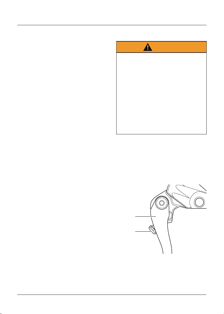
General Information
60
For all of the conditions mentioned
contact an authorised Triumph dealer
as soon as possible to have the fault
checked and rectified.
Clutch Lever Adjusters
Warning
Do not attempt to adjust the levers
with the motorcycle in motion as this
may lead to loss of motorcycle control
and an accident.
After adjusting the levers, operate the
motorcycle in an area free from traffic
to gain familiarity with the new lever
setting.
Do not loan your motorcycle to anyone
as they may change the lever setting
from the one you are familiar with
causing loss of motorcycle control and
an accident.
An adjuster is fitted to the front clutch
lever. The adjuster allows the distance
from the handlebar to the clutch lever
to be changed to suit the span of the
rider's hands.
Speed Twin Only
2
1
1. Clutch lever
2. Adjusting screw
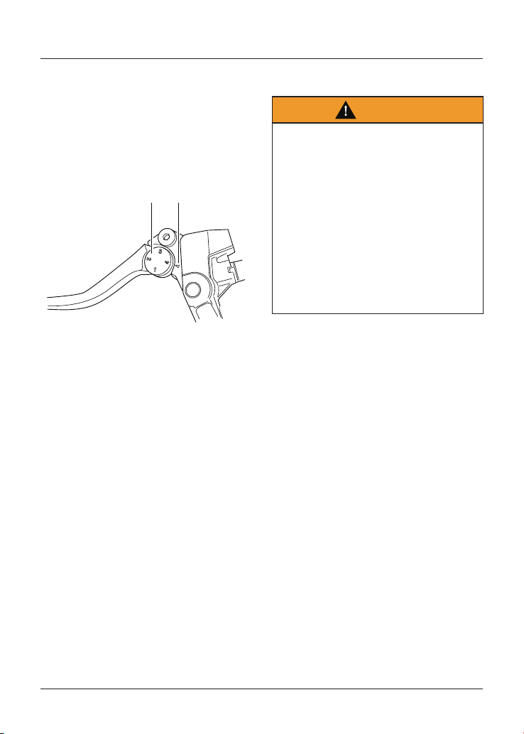
General Information
61
To adjust the clutch lever:
• Push the clutch lever forward
and turn the adjusting screw in
to increase the distance or out
to shorten the distance from the
handlebar.
All Other Models
1 2
1. Clutch lever adjuster wheel
2. Arrow mark
To adjust the clutch lever:
• Push the clutch lever forward and
turn the adjuster wheel to align
one of the numbered positions with
the arrow mark on the clutch lever
holder.
• The distance from the handlebar
grip to the released clutch lever is
shortest when set to number four,
and longest when set to number
one.
Brake Lever Adjusters
Warning
Do not attempt to adjust the levers
with the motorcycle in motion as this
may lead to loss of motorcycle control
and an accident.
After adjusting the levers, operate the
motorcycle in an area free from traffic
to gain familiarity with the new lever
setting.
Do not loan your motorcycle to anyone
as they may change the lever setting
from the one you are familiar with
causing loss of motorcycle control and
an accident.
An adjuster is fitted to the front brake
lever. The adjuster allows the distance
from the handlebar to the brake lever
to be changed to suit the span of the
rider's hands.
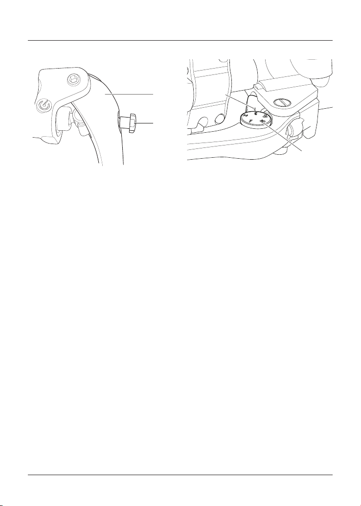
General Information
62
Speed Twin and Thruxton RS Only
1
2
1. Brake lever
2. Adjusting screw
To adjust the brake lever:
• Push the brake lever forward
and turn the adjusting screw in
to increase the distance or out
to shorten the distance from the
handlebar.
All Other Models
2
1
1. Brake lever adjuster wheel
2. Arrow mark
To adjust the brake lever:
• Push the brake lever forward and
turn the adjuster wheel to align
one of the numbered positions with
the arrow mark on the brake lever
holder.
• The distance from the handlebar
grip to the released brake lever is
shortest when set to number five,
and longest when set to number
one.
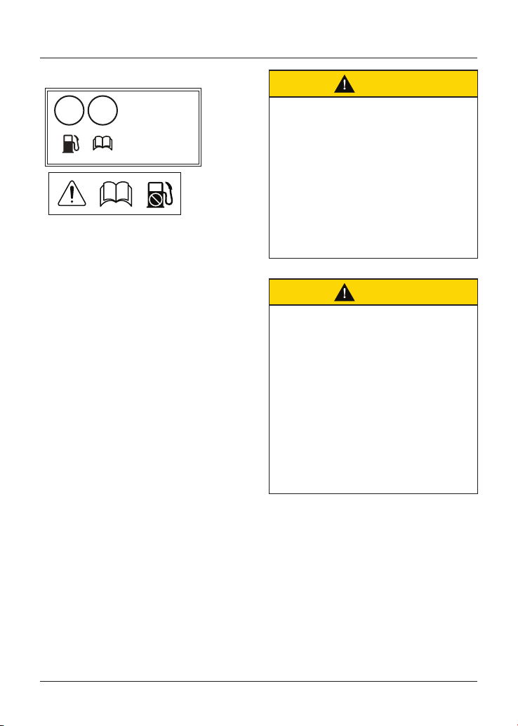
General Information
63
Fuel
RON/ROZ
95
min.
91
E5 E10
3900691
Unleaded fuel only
Carburant san plomb
Gasolina sin plomo
Bleifreies Benzin
Endast blyfri bensin
Benzina senza piombo
Ongelode Brandstof
Combustival sem schumbo
P
b
Fuel Grade
Triumph motorcycles are designed to
use unleaded fuel and will give optimum
performance if the correct grade of fuel
is used. Always use unleaded fuel with a
minimum octane rating of 91 RON.
Ethanol
In Europe, Triumph motorcycles are
compatible with Ethanol E5 and E10 (5%
and 10% Ethanol) unleaded fuel.
In all other markets Ethanol up to E25
(25% Ethanol) may be used.
Engine Calibration
In certain circumstances engine
calibration may be required. Always
refer to your authorised Triumph dealer.
Caution
The motorcycle can be permanently
damaged if it is allowed to operate
with the incorrect grade of fuel or
incorrect engine calibration.
Always make sure the fuel used is of
the correct grade and quality.
Damage caused by using the
incorrect fuel or engine calibration
is not considered a manufacturing
defect and will not be covered under
warranty.
Caution
The exhaust system for this
motorcycle is fitted with a catalytic
converter to help reduce exhaust
emission levels.
Use of leaded fuel will damage the
catalytic converter. In addition,
the catalytic converter can be
permanently damaged if the
motorcycle is allowed to run out of
fuel or if the fuel level is allowed to get
very low.
Always make sure you have adequate
fuel for your journey.
Note
The use of leaded fuel is illegal in some
countries, states or territories.
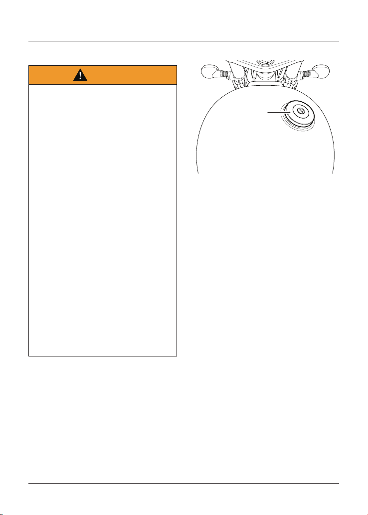
General Information
64
Refuelling
Warning
To help reduce hazards associated
with refuelling, always observe the
following fuel safety instructions:
- Petrol (fuel) is highly flammable
and can be explosive under certain
conditions. When refuelling, turn the
ignition switch to the OFF position.
- Do not smoke.
- Do not use a mobile telephone.
- Make sure the refuelling area is well
ventilated and free from any source
of flame or sparks. This includes any
appliance with a pilot light.
- Never fill the tank until the fuel level
rises into the filler neck. Heat from
sunlight or other sources may cause
the fuel to expand and overflow
creating a fire hazard.
- After refuelling always check that
the fuel filler cap is correctly closed.
- Because petrol (fuel) is highly
flammable, any fuel leak or spillage,
or any failure to observe the safety
advice given above will lead to a fire
hazard, which could cause damage to
property, injury to persons or death.
Fuel Tank Cap
1
1. Fuel tank cap
To open the fuel tank cap:
• Remove the cap cover or lift up the
cap flap.
• Insert the key into the lock and turn
the key clockwise.
• Rotate the cap anticlockwise and lift
clear of the tank filler neck.
To close and lock the fuel tank cap:
• Align the cap to the tank filler neck
and rotate the cap clockwise until
the cap seals against the filler neck.
• In the fully closed position, a ratchet
mechanism prevents overtightening
of the cap by allowing the outer part
of the cap to turn independently of
the internal part.
• Turn the key anticlockwise to lock
and withdraw the key.
• Replace the cap cover or securely
close the cap flap.
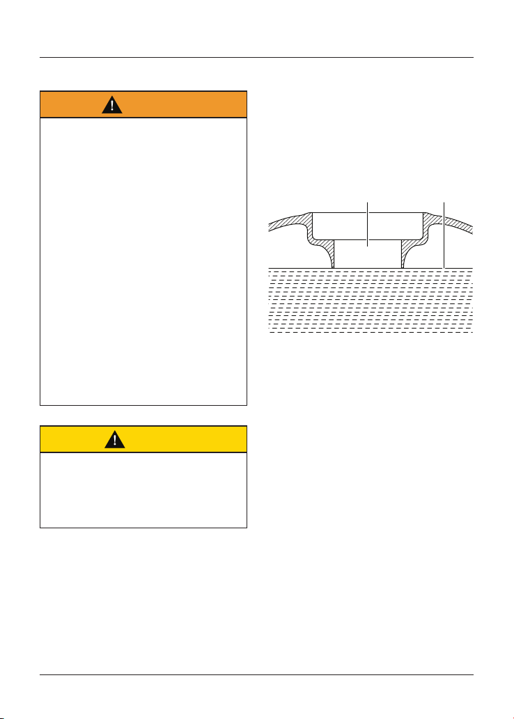
General Information
65
Filling the Fuel Tank
Warning
Overfilling the tank can lead to fuel
spillage.
If fuel is spilled, thoroughly clean up
the spillage immediately and dispose of
the materials used safely.
Take care not to spill any fuel on the
engine, exhaust pipes, tyres or any
other part of the motorcycle.
Because fuel is highly flammable, any
fuel leak or spillage, or any failure to
observe the safety advice given above
may lead to a fire hazard, which could
cause damage to property and injury
or death to persons.
Fuel spilled near to, or onto the tyres
will reduce the tyres’ ability to grip the
road. This will result in a dangerous
riding condition potentially causing
loss of motorcycle control and an
accident.
Caution
Avoid filling the tank in rainy or dusty
conditions where airborne material can
contaminate the fuel.
Contaminated fuel may cause damage
to fuel system components.
Fill the fuel tank slowly to help prevent
spillage. Do not fill the tank to a level
above the bottom of the filler neck.
This will make sure there is enough air
space to allow for fuel expansion if the
fuel inside the tank expands through
absorption of heat from the engine or
from direct sunlight.
2
1
1. Fuel filler neck
2. Maximum fuel level
After refuelling always check that the
fuel filler cap is correctly closed.
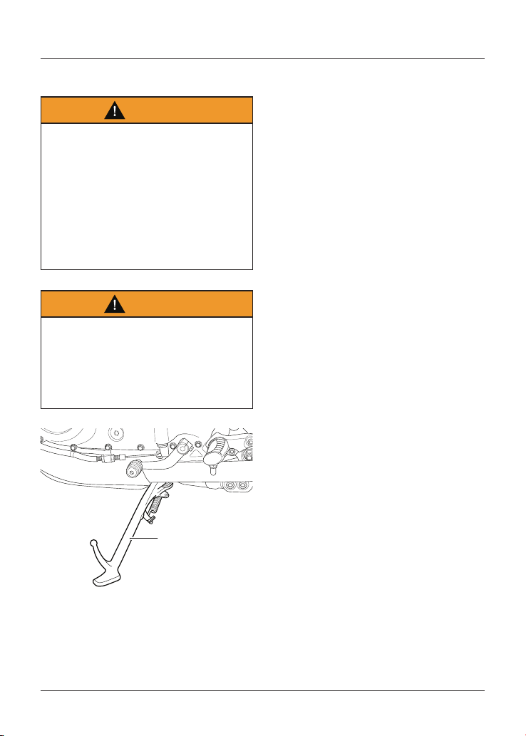
General Information
66
Side Stand
Warning
The motorcycle is fitted with an
interlock system to prevent it from
being ridden with the side stand in the
down position.
Never attempt to ride with the side
stand down or interfere with the
interlock mechanism as this will cause
a dangerous riding condition leading
to loss of motorcycle control and an
accident.
Warning
Do not lean, sit or climb on the
motorcycle when it is supported on
the side stand.
This may cause the motorcycle to fall
over leading to motorcycle damage
and an accident.
1
1. Side stand
The motorcycle is equipped with a side
stand on which it can be parked. When
using the side stand, always turn the
handlebars fully to the left and leave
the motorcycle in first gear.
Whenever the side stand is used, before
riding, always make sure that the stand
is fully up after first sitting on the
motorcycle.
For instructions on safe parking, refer
to the 'How to Ride the Motorcycle'
section.
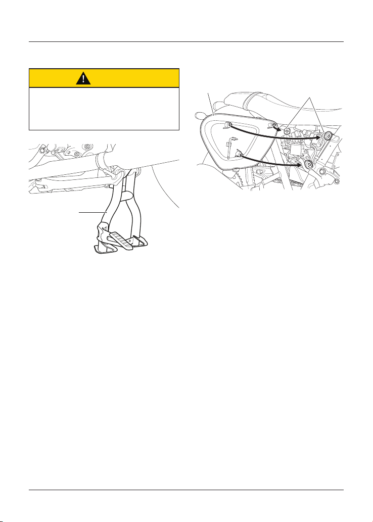
General Information
67
Centre Stand (if fitted)
Caution
Do not use body panels or the seat
as a handhold when placing the
motorcycle on the centre stand as this
will cause damage.
1
1. Centre stand
To set the motorcycle on the centre
stand:
• Hold the motorcycle upright.
• Step down firmly on the foot finder
part of the stand.
• Lift the motorcycle up and to the
rear using the rear frame as a
handhold.
For instructions on safe parking, refer
to the How to Ride the Motorcycle
section.
Side Panels
All Models except Street Scrambler
citf
1
2
2
1. Side panel (right hand shown)
2. Grommets
The right side panel can be removed to
gain access to the adjustment tool and
the rear brake fluid reservoir.
To remove either side panel:
• Grasp the panel firmly and pull the
panel away from the motorcycle
until it is free from the three
retaining grommets (leaving the
grommets in place).
To refit either side panel:
• Position the three locating dowels to
the grommets, then press firmly to
secure the panel.
• Finally, grasp the panel and make
sure that it is fully retained.
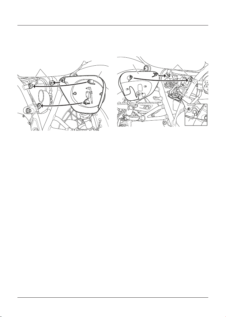
General Information
68
Street Scrambler
Left Hand Side Panel
The left hand side panel can be removed
to gain access to the adjustment tool.
2
1
2
1. Side panel (left hand shown)
2. Grommets
To remove the left hand side panel:
• Grasp the panel firmly and pull the
panel away from the motorcycle
until it is free from the three
retaining grommets (leaving the
grommets in place).
To refit the left hand side panel:
• Position the three locating dowels to
the grommets, then press firmly to
secure the panel.
• Finally, grasp the panel and make
sure that it is fully retained.
Right Hand Side Panel
The right hand side panel can be
removed to gain access to the rear
brake fluid reservoir.
1
3
4
2
1. Side panel (right hand shown)
2. Upper grommets
3. Lower grommets
4. Side panel attached to lower grommet
Note
The exhaust system is shown removed
for clarity.
To remove the right hand side panel:
• Grasp the panel firmly at the top
and pull the panel away from the
motorcycle until it is free from the
two top retaining grommets, leaving
the grommets in place.
• Lift up the panel to detach it from
the lower grommet.
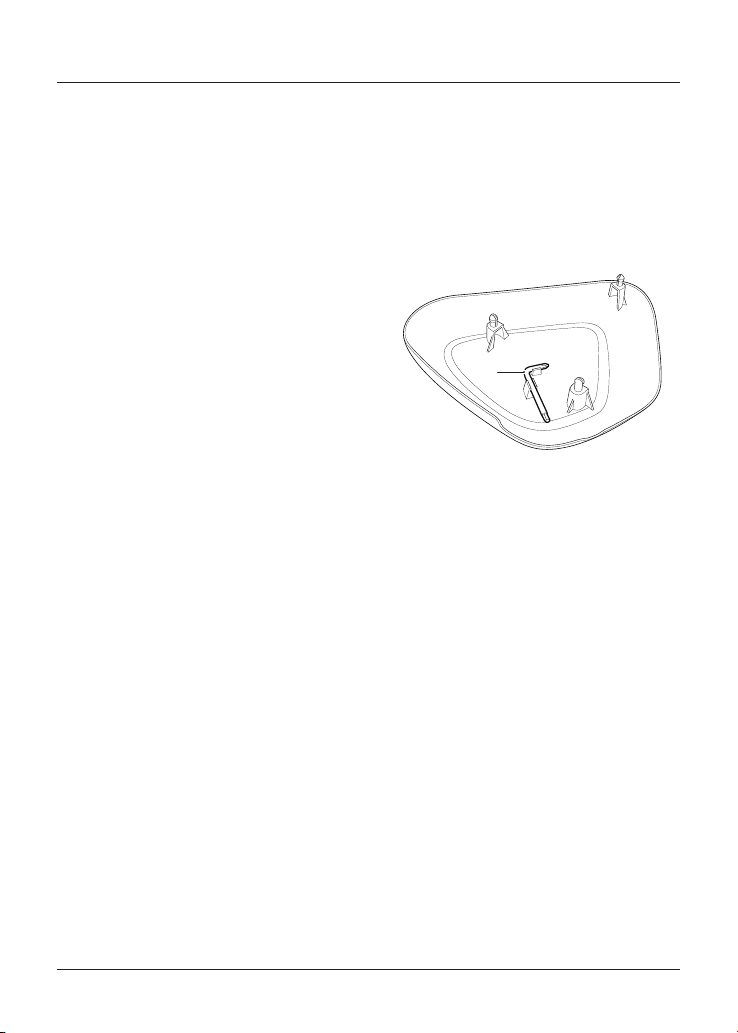
General Information
69
To refit the right hand side panel:
• Position the side panel on to the
lower grommet.
• Make sure that the slot in the panel
is fully engaged with the lower
grommet.
• Position the two locating dowels to
the upper grommets, then press
firmly to secure the panel.
• Finally, grasp the panel and make
sure that it is fully retained.
Tool Kit and Owner’s
Handbook
Tool Kit
The tool kit consists of an adjustment
tool for all models, and additional
C-spanners for Thruxton RS.
1
1. Adjustment tool
Bonneville T100 (all models),
Bonneville T120 (all models),
Speed Twin, Street Twin and
Thruxton RS
The adjustment tool is attached to the
inside of the right hand side panel.
Street Scrambler
The adjustment tool is attached to the
inside of the left hand side panel.
Thruxton RS
There are two C-spanners located under
the seat.
General Information
70
Owner’s Handbook
Bonneville T100 (all models),
Bonneville T120,
Bonneville T120 Bud Ekins,
Bonneville T120 Diamond and
Thruxton RS
The Owner’s Handbook is located under
the seat on the rear mudguard.
Bonneville T120 Ace, Speed Twin
and Street Scrambler
The Owner’s Handbook is supplied
separately.
Street Twin
The Owner’s Handbook is located on the
underside of the seat.
Helmet Hook (if fitted)
Warning
Never ride the motorcycle with
helmet(s) secured to the helmet hook
as this may cause the motorcycle to
become unstable leading to loss of
control and an accident.
Caution
Do not allow helmet(s) to rest against
a hot silencer. The helmet may be
damaged.
A helmet can be secured to the
motorcycle using the helmet hook
located on the left hand side of the
motorcycle, beneath the seat.
To attach a helmet to the motorcycle:
• Remove the seat (see page 72) and
loop the helmet chin strap over the
hook.
• Make sure the flat area above
the hook is not obstructed by the
helmet strap, as this will prevent the
seat engaging correctly.
• To secure the helmet, refit the seat
and lock into position.
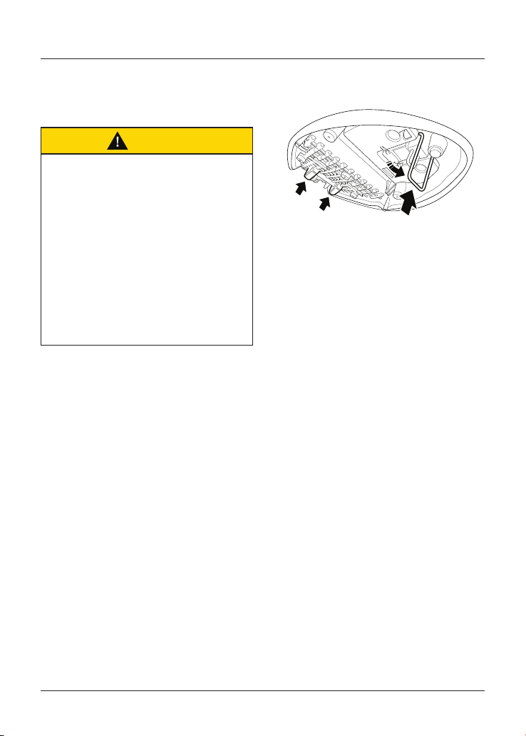
General Information
71
Seats
Seat Care
Caution
To prevent damage to the seats or
seat covers, care must be taken not to
drop the seats.
Do not lean the seats against the
motorcycle or any surface which may
damage the seats or seat covers.
Instead, place the seats, with the seat
cover facing upwards, on a clean, flat
surface which is covered with a soft
cloth.
Do not place any item on the seats
which may cause damage or staining
to the seat covers.
Thruxton RS Only
Seat Stand
To prevent damage to the seat after
removing:
• Release the metal stand from the
underside of the seat.
• Place the seat cover facing
upwards, on a clean, flat surface
using the metal stand and two
plastic stands at the rear of the
seat to rest on.
• See page 157 for seat cleaning
information.
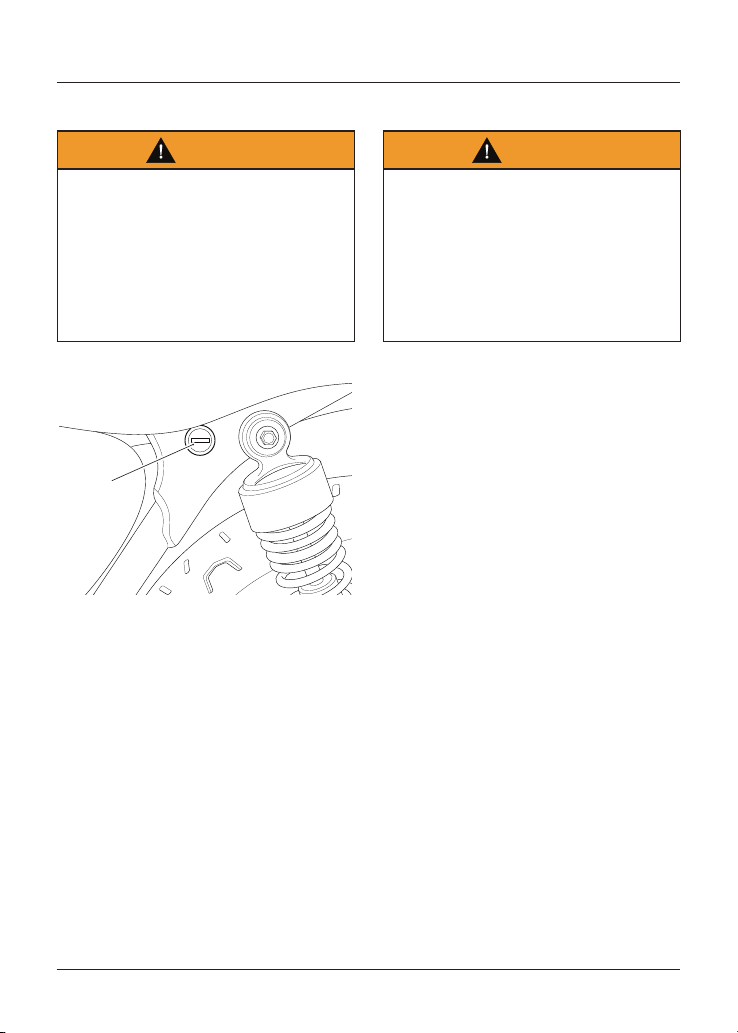
General Information
72
Seat Lock
Warning
To prevent detachment of the seat
during riding, after fitting always
grasp the seat and pull firmly upwards.
If the seat is not correctly secured in
the lock, it will detach from the lock.
A loose or detached seat may cause
loss of motorcycle control and an
accident.
1
1. Seat lock
The seat lock is located on the left hand
side of the motorcycle, on the frame
below the seat.
The seat can be removed to gain access
to the battery, fuse box (on certain
models) and Owner's Handbook.
Seat Removal and Installation
Warning
To prevent detachment of the seat
during riding, after fitting always
grasp the seat and pull firmly upwards.
If the seat is not correctly secured in
the lock, it will detach from the lock.
A loose or detached seat may cause
loss of motorcycle control and an
accident.
All Models except Street Scrambler
Seat Removal
To remove the seat:
• Insert the ignition key into the seat
lock and turn it anticlockwise. This
will release the seat from its lock.
• Slide the seat upwards and
rearwards for complete removal
from the motorcycle.
Seat Installation
To refit the seat:
• Engage the seat's tongue
underneath the bracket near the
fuel tank.
• Line up the hinges and press down
at the rear to engage the seat lock.
Note
An audible click can be heard when the
seat is fully engaged into its lock.
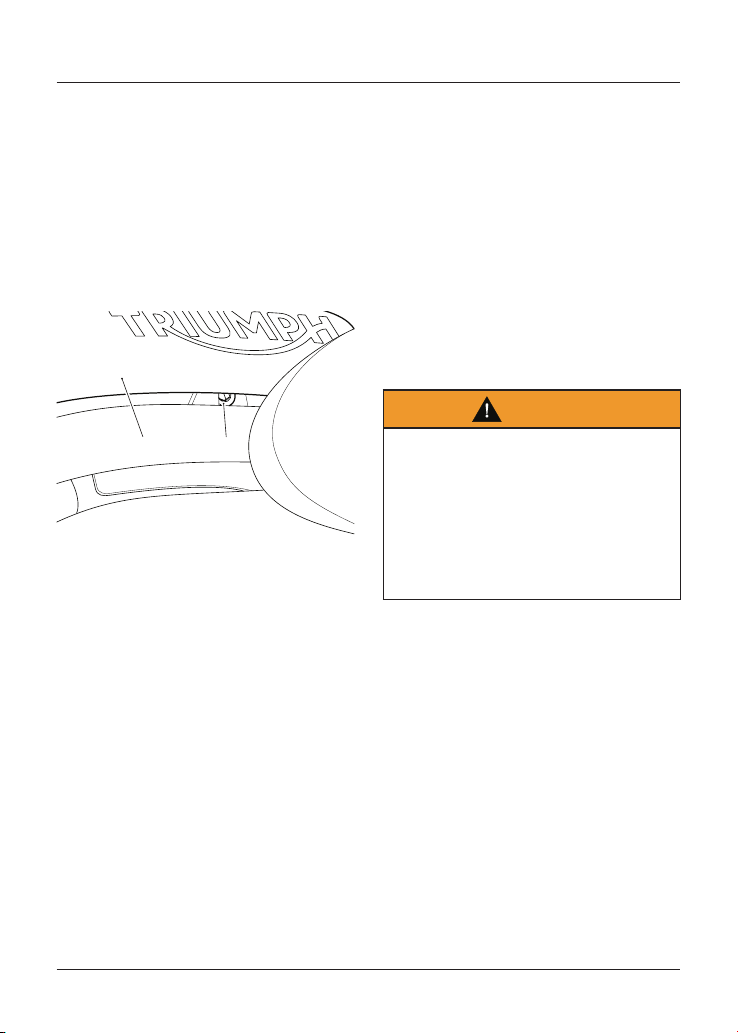
General Information
73
Street Scrambler Seat Removal
Note
If a passenger seat is fitted, it must be
removed before removing the rider’s
seat.
If a luggage rack is fitted, the rider’s
seat can be removed without removing
the luggage rack.
Passenger Seat Removal
cjyn
2
1
1. Passenger seat
2. Fixing
To remove the passenger seat:
• Remove the fixing securing the
passenger seat to the luggage rack
subframe.
• Lift the seat up from the back and
slide rearwards to remove it from
the motorcycle.
Rider’s Seat Removal
To remove the rider’s seat:
• Remove the passenger seat if fitted.
• Insert the ignition key into the seat
lock and turn it anticlockwise while
pressing down on the rear of the
seat. This will release the seat from
its lock.
• Lift the seat up from the back and
slide rearwards to remove it from
the motorcycle.
Street Scrambler Seat Installation
Warning
To prevent detachment of the seat
during riding, after fitting always
grasp the seat and pull firmly upwards.
If the seat is not correctly secured in
the lock, it will detach from the lock.
A loose or detached seat may cause
loss of motorcycle control and an
accident.
Rider’s Seat Installation
To install the rider’s seat:
• Engage the seat’s tongue under the
fuel tank.
• Press firmly down in the centre of
the seat to engage the lock.
• An audible click can be heard when
the seat is correctly engaged in the
lock.
• Grasp the seat and make sure it is
securely retained.
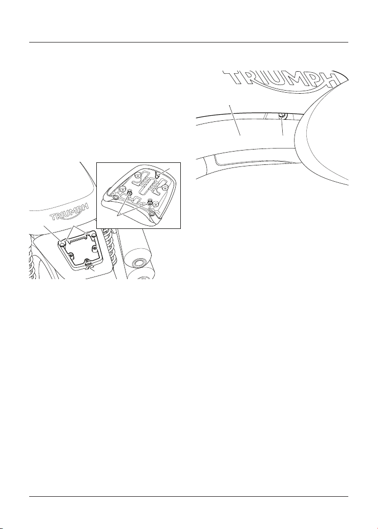
General Information
74
Passenger Seat Installation
To install the passenger seat:
• Make sure that the rider’s seat is
correctly fitted.
• Align the front locating lugs on the
passenger seat to their locating
slots on the luggage rack subframe.
• Gently push the seat forward until
the rear locating lug fits into its hole
on the luggage rack subframe.
4
5
2
3
1
1. Luggage rack subframe
2. Front locating lugs
3. Front locating lug slots
4. Rear locating lug
5. Rear locating lug hole
• Secure the seat with its fixing and
tighten to 3 Nm.
cjyn
2
1
1. Passenger seat
2. Fixing
• Grasp the seat and make sure that
it is securely retained.
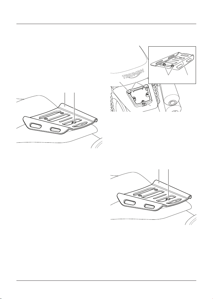
General Information
75
Luggage Rack
Street Scrambler Only
Note
If a luggage rack is fitted, the rider’s
seat can be removed without removing
the luggage rack.
Removal
21
1. Luggage rack
2. Screw
To remove the luggage rack:
• Remove the screw securing the
luggage rack to the luggage rack
subframe.
• Lift the luggage rack up from the
back and slide rearwards to remove
it from the luggage rack subframe.
Installation
To install the luggage rack:
• Make sure that the rider’s seat is
correctly fitted.
• Align the front locating lugs on the
luggage rack to their locating slots
on the luggage rack subframe.
• Gently push the luggage rack
forward until the locating lugs are
secure.
3
1
5
42
1. Luggage rack subframe
2. Locating lugs
3. Locating lug slots
4. Locating screw position
5. Locating screw hole
• Secure the luggage rack with its
screw in the locating screw hole and
tighten to 8 Nm.
21
1. Luggage rack
2. Screw
• Grasp the luggage rack and make
sure that it is securely retained.
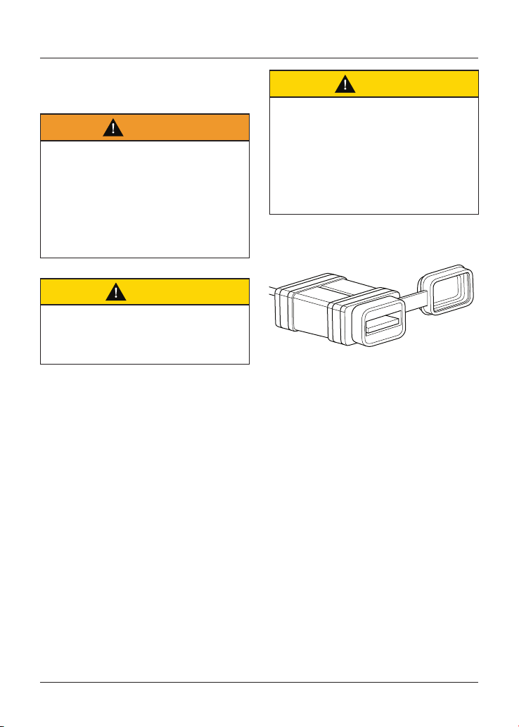
General Information
76
Universal Serial Bus (USB)
Socket
Warning
The USB socket is not waterproof
unless the waterproof cap is installed.
Do not connect electronic devices
whilst it is raining.
Water in the USB socket could lead
to an electrical problem, resulting in
motorcycle damage, loss of motorcycle
control and an accident.
Caution
Do not leave the ignition switch in
the ON position unless the engine
is running as this will discharge the
battery.
Caution
Make sure that all electronic devices
and cables are safely secured under
the seat when riding.
Make sure there is sufficient space
surrounding any electronic devices for
the seat to close without causing any
damage to the electronic device or the
motorcycle.
USB Port Socket
The Universal Serial Bus (USB) socket
allows a 5 Volt USB connection for
charging electronic devices such as
mobile phones, cameras and GPS
devices.
Loads up to two Amps can be
connected to the USB socket.
To access the USB socket:
• Remove the seat (see page 72).
• The USB socket is located on top of
the battery.
• Remove the cap.
• Plug the relevant USB adaptor cable
into the socket. Adaptor cables are
not supplied with the motorcycle.

General Information
77
Running-In
R.P.M.
Running-in is the name given to the
process that occurs during the first
hours of a new vehicle's operation.
In particular, internal friction in the
engine will be higher when components
are new. Later on, when continued
operation of the engine has ensured
that the components have 'bedded
in', this internal friction will be greatly
reduced.
A period of careful running-in will
ensure lower exhaust emissions, and
will optimise performance, fuel economy
and longevity of the engine and other
motorcycle components.
During the first 500 miles (800 km):
• Do not use full throttle;
• Avoid high engine speeds at all
times;
• Avoid riding at one constant engine
speed, whether fast or slow, for a
long period of time;
• Avoid aggressive starts, stops, and
rapid accelerations, except in an
emergency;
• Do not ride at speeds greater than
3/4 of maximum speed.
From 500 to 1,000 miles (800 to
1,500 km):
• Engine speed can gradually be
increased to the rev limit for short
periods.
Both during and after running-in has
been completed:
• Do not overrev the engine when
cold;
• Do not let the engine labour. Always
downshift before the engine begins
to 'struggle';
• Do not ride with engine speeds
unnecessarily high. Changing up a
gear helps reduce fuel consumption,
reduces noise and helps to protect
the environment.
General Information
78
Daily Safety Checks
Warning
Failure to perform these checks
every day before you ride may result
in serious motorcycle damage or an
accident causing serious injury or
death.
Check the following items each day
before you ride. The time required is
minimal, and these checks will help
ensure a safe, reliable ride.
If any irregularities are found during
these checks, refer to the Maintenance
and Adjustment section or see your
authorised Triumph dealer for the action
required to return the motorcycle to a
safe operating condition.
Check:
Fuel: Adequate supply in tank, no fuel
leaks (see page 65).
Engine Oil: Correct level on dipstick
or shown in sight glass. Add correct
specification oil as required. No leaks
from the engine or oil cooler (see
page 101).
Drive Chain: Correct adjustment (see
page 111).
Tyres/Wheels: Correct inflation
pressures (when cold). Tread depth/
wear, tyre/wheel damage, loose/broken
spokes, punctures etc. (see page 134).
Nuts, Bolts, Fasteners: Visually
check that steering and suspension
components, axles, and all controls are
properly tightened or fastened. Inspect
all areas for loose/damaged fixings.
Steering Action: Smooth but not loose
from lock to lock. No binding of any of
the control cables (see page 126).
Brakes: Pull the brake lever and push
the brake pedal to check for correct
resistance. Investigate any lever/pedal
where the travel is excessive before
meeting resistance, or if either control
feels spongy in operation (see page 115).
Brake Pads: Check that the correct
amount of friction material is remaining
on all the brake pads (see page 115).
Brake Fluid Levels: No brake fluid
leakage. Brake fluid levels must be
between the MAX and MIN marks on
both reservoirs (see page 117).
Front Forks: Smooth action. No fork oil
leakage (see page 129).
Throttle: Make sure that the throttle
grip returns to the idle position without
sticking (see page 108).
Clutch: Smooth operation and correct
cable free play (see page 109).
Coolant: No coolant leakage. Check the
coolant level in the expansion tank
(when the engine is cold) (see page 105).
Electrical Equipment: All lights and horn
function correctly (see page 57).
Engine Stop: Engine start/stop switch
turns the engine OFF when the switch
is moved to the STOP position (see
page 55).
Stands: Returns to the fully up position
by spring tension. Return springs not
weak or damaged (see page 66).

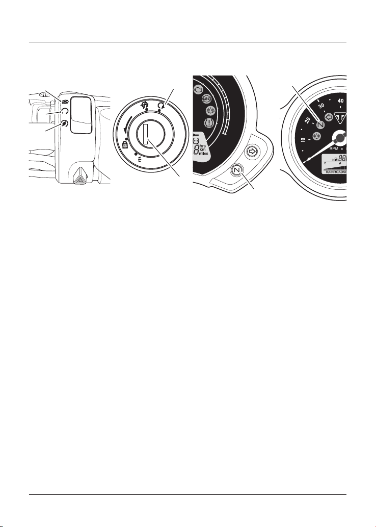
How to Ride the Motorcycle
80
How to Ride the Motorcycle
P
U
S
H
P
5
4
1
3
2
7
cixa
10
20
30
40
50
60
70
80
90
100
110
120
130
0
0
20
40
60
80
100
120
140
160
180
200
6
MPH
km/h
1. STOP position
2. RUN position
3. START position
4. Ignition switch
5. ON position
6. Neutral indicator light (Street Scrambler
and Street Twin)
7. Neutral indicator light (all other models)
How to Ride the Motorcycle
81
Stopping the Engine
Caution
The engine should normally be
stopped by turning the ignition switch
to the OFF position.
The engine stop switch is for
emergency use only.
Do not leave the ignition switched on
with the engine stopped. Electrical
damage may result.
To stop the engine:
• Close the throttle completely.
• Select neutral.
• Turn the ignition switch off.
• Select first gear.
• Position the motorcycle on a firm,
level surface with the side stand
(see page 87).
• Lock the steering (see page 53).
Starting the Engine
Warning
Never start the engine or run the
engine in a confined area.
Exhaust fumes are poisonous and can
cause loss of consciousness and death
within a short period of time.
Always operate the motorcycle in the
open air or in an area with adequate
ventilation.
Caution
Do not operate the starter
continuously for more than five
seconds as the starter motor will
overheat and the battery will become
discharged.
Wait 15 seconds between each
operation of the starter to allow for
cooling and recovery of battery power.
Do not let the engine idle for
long periods as this may lead to
overheating which will cause damage
to the engine.
Caution
The low oil pressure warning light
should go out shortly after the engine
starts.
If the low oil pressure warning light
stays on after starting the engine,
stop the engine immediately and
investigate the cause.
How to Ride the Motorcycle
82
Caution Continued
Running the engine with low oil
pressure will cause severe engine
damage.
To start the engine:
• Check that the engine stop switch is
in the RUN position.
• Make sure the transmission is in
neutral.
• Turn the ignition switch on.
Note
When the ignition is switched on, the
instrument warning lights will illuminate
and will then go off (except those which
normally remain on until the engine
starts, see the Warning Lights section).
• Pull the clutch lever fully into the
handlebar.
• Leaving the throttle fully closed,
push the starter button until the
engine starts.
• The motorcycle is equipped with
starter lockout switches. The
switches prevent the electric
starter from operating when the
transmission is not in neutral with
the side stand down.
• If the side stand is extended whilst
the engine is running, and the
transmission is not in neutral then
the engine will stop regardless of
the clutch lever position.
Moving Off
To move the motorcycle:
• Pull in the clutch lever and select
first gear.
• Open the throttle a little and let out
the clutch lever slowly.
• As the clutch starts to engage, open
the throttle a little more, allowing
enough engine speed to avoid
stalling.
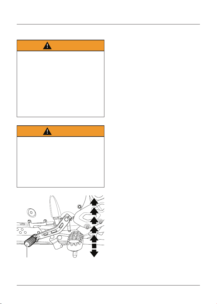
How to Ride the Motorcycle
83
Changing Gears
Warning
Take care to avoid opening the throttle
too far or too fast in any of the lower
gears as this can lead to the front
wheel lifting from the ground (pulling a
'wheelie') and to the rear tyre breaking
traction (wheel spin).
Always open the throttle cautiously,
particularly if you are unfamiliar with
the motorcycle, as a 'wheelie' or loss of
traction will cause loss of motorcycle
control and an accident.
Warning
Do not change to a lower gear at
speeds that will cause excessive
engine rpm (r/min).
This can lock the rear wheel causing
loss of control and an accident. Engine
damage may also be caused.
Changing down should be done such
that low engine speeds will be ensured.
1
5
4
3
6
2
N
1
1. Gear change pedal (6 speed shown)
To change gear:
• Close the throttle while pulling in the
clutch lever.
• Change into the next higher or
lower gear.
• Open the throttle part way, while
releasing the clutch lever. Always
use the clutch when changing gear.
Note
The gear change mechanism is the
'positive stop' type. This means that,
for each movement of the gear change
pedal, you can only select each gear,
one after the other, in ascending or
descending order.
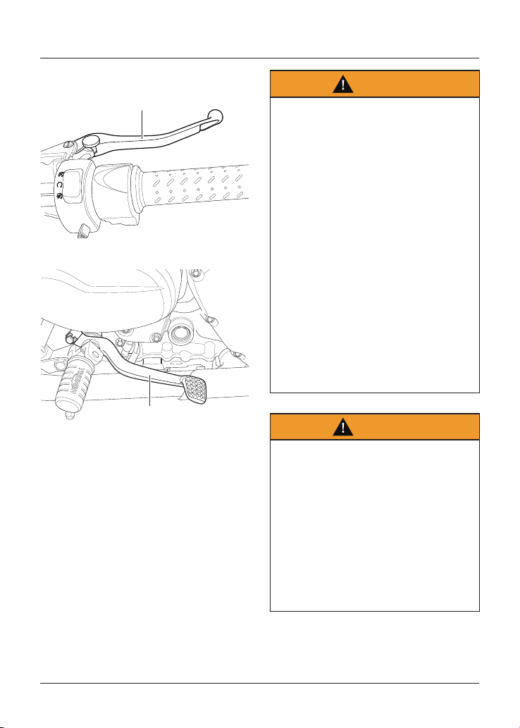
How to Ride the Motorcycle
84
Braking
1
1. Front brake lever
1
1. Rear brake pedal
Warning
WHEN BRAKING, OBSERVE THE
FOLLOWING:
- Close the throttle completely,
leaving the clutch engaged to allow
the engine to help slow down the
motorcycle.
- Change down one gear at a time
such that the transmission is in first
gear when the motorcycle comes to
a complete stop.
- When stopping, always apply both
brakes at the same time. Normally
the front brake should be applied a
little more than the rear.
- Change down or fully disengage
the clutch as necessary to keep the
engine from stalling.
- Never lock the brakes, as this
may cause loss of control of the
motorcycle and an accident.
Warning
For emergency braking, disregard
down changing, and concentrate on
applying the front and rear brakes
as hard as possible without skidding.
Riders should practice emergency
braking in a traffic-free area.
Triumph strongly recommends that
all riders take a course of instruction,
which includes advice on safe brake
operation. Incorrect brake technique
could result in loss of control and an
accident.
How to Ride the Motorcycle
85
Warning
For your safety, always exercise
extreme caution when braking,
accelerating or turning as any
incautious action can cause loss of
control and an accident. Independent
use of the front or rear brakes
reduces overall braking performance.
Extreme braking may cause either
wheel to lock, reducing control of the
motorcycle and causing an accident
(see ABS warnings below).
When possible, reduce speed or brake
before entering a turn as closing the
throttle or braking in mid-turn may
cause wheel slip leading to loss of
control and an accident.
When riding in wet or rainy conditions,
or on loose surfaces, the ability to
manoeuvre and stop will be reduced.
All of your actions should be smooth
under these conditions. Sudden
acceleration, braking or turning may
cause loss of control and an accident.
Warning
When descending a long, steep
gradient or mountain pass, make use
of the engine's braking effect by down
changing and use both front and rear
brakes intermittently.
Continuous brake application or use of
the rear brake only can overheat the
brakes and reduce their effectiveness
leading to loss of motorcycle control
and an accident.
Warning
Riding with your foot on the brake
pedal or your hands on the brake lever
may actuate the brake light, giving a
false indication to other road users.
It may also overheat the brake,
reducing braking effectiveness leading
to loss of motorcycle control and an
accident.
Warning
Do not coast with the engine switched
off, and do not tow the motorcycle.
The transmission is pressure
lubricated only when the engine is
running.
Inadequate lubrication may cause
damage or seizure of the transmission,
which can lead to sudden loss of
motorcycle control and an accident.
How to Ride the Motorcycle
86
Anti-lock Braking System (ABS)
Warning
ABS prevents the wheels from locking,
therefore maximising the effectiveness
of the braking system in emergencies
and when riding on slippery surfaces.
The potentially shorter braking
distances ABS allows under certain
conditions are not a substitute for
good riding practice.
Always ride within the legal speed limit.
Never ride without due care and
attention and always reduce speed
in consideration of weather, road and
traffic conditions.
Take care when cornering. If the
brakes are applied in a corner, ABS will
not be able to counteract the weight
and momentum of the motorcycle.
This can result in loss of control and
an accident.
Under some circumstances it is
possible that a motorcycle equipped
with ABS may require a longer
stopping distance.
Warning
If the ABS is not functioning or has
been disabled (Street Scrambler only),
the brake system will continue to
function as a non-ABS braking system.
Do not continue to ride for longer than
is necessary with the warning light
illuminated. In the event of a fault,
contact an authorised Triumph dealer
as soon as possible to have the fault
checked and rectified.
Warning Continued
In this situation, braking too hard will
cause the wheels to lock resulting
in loss of motorcycle control and an
accident.
Warning
After riding off-road with ABS
disabled, always make sure that the
ABS is enabled when returning to ride
on public roads.
Riding on public roads with the ABS
disabled will, if braking too hard, cause
the wheels to lock resulting in loss of
motorcycle control and an accident.
Note
The ABS operation may feel like a harder
pedal pressure or a pulsation of the
brake lever and pedal.
The ABS is not an integrated braking
system and does not control both the
front and rear brake at the same time
so this pulsation may be felt in the lever,
the pedal or both.
The ABS may be activated by sudden
upward or downward changes in the
road surface.
ABS Warning Light
When the ignition switch is
turned to the ON position, it is
normal that the ABS warning
light will flash on and off. The
light will continue to flash after engine
start-up until the motorcycle first
reaches a speed exceeding 6 mph
(10 km/h) when it will go off.
How to Ride the Motorcycle
87
The warning light will not illuminate
again until the engine is restarted
unless there is a fault, or the ABS is
disabled by the rider (Street Scrambler
only).
If the ABS is disabled by the rider
(Street Scrambler only) then the
warning light will illuminate until the
ABS is enabled again.
If there is a fault with the ABS system
the warning light will be illuminated and
the general warning symbol will flash.
Warning
The ABS warning light will illuminate
when the rear wheel is driven at high
speed for more than 30 seconds when
the motorcycle is on a stand. This
reaction is normal.
When the ignition is switched off
and the motorcycle is restarted, the
warning light will illuminate until the
motorcycle reaches a speed exceeding
19 mph (30 km/h).
Warning
The ABS system operates by
comparing the relative speed of the
front and rear wheels.
Use of non-recommended tyres can
affect wheel speed and cause the ABS
function not to operate, potentially
leading to loss of control and an
accident in conditions where the ABS
would normally function.
Parking
Warning
Do not park on a soft or steeply
inclined surface.
Parking under these conditions may
cause the motorcycle to fall over
causing damage to property and
personal injury.
Warning
Petrol is extremely flammable and can
be explosive under certain conditions.
If parking inside a garage or other
structure, be sure it is well ventilated
and the motorcycle is not close to
any source of flame or sparks. This
includes any appliance with a pilot
light.
Failure to follow the above advice may
cause a fire resulting in damage to
property or personal injury.
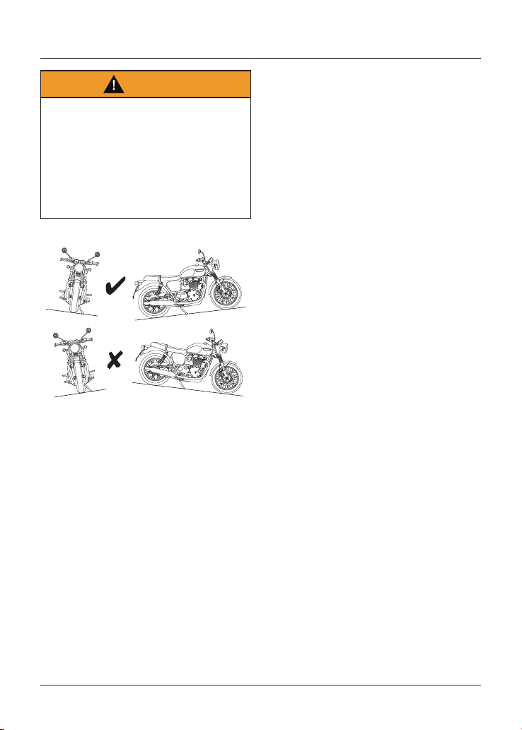
How to Ride the Motorcycle
88
Warning
The engine and exhaust system will be
hot after riding.
DO NOT park where pedestrians
and children are likely to touch the
motorcycle.
Touching any part of the engine or
exhaust system when hot may cause
unprotected skin to become burnt.
To park the motorcycle:
• Select neutral and turn the ignition
switch to the OFF position.
• Lock the steering to help prevent
theft.
• Always park on a firm, level surface
to prevent the motorcycle from
falling.
• When parking on a hill, always
park facing uphill to prevent the
motorcycle from rolling off the
stand. Engage first gear to prevent
the motorcycle from moving.
• On a lateral (sideways) incline,
always park such that the incline
naturally pushes the motorcycle
towards the sidestand.
• Do not park on a lateral (sideways)
incline of greater than 6° and never
park facing downhill.
• Make sure that the side stand is
fully retracted before riding off.
• Do not leave the switch in the P
position for long periods of time as
this will discharge the battery.
Note
When parking near traffic at night,
or when parking in a location where
parking lights are required by law, leave
the tail, licence plate and position lights
on by turning the ignition switch to P
(PARK).
How to Ride the Motorcycle
89
Considerations for High
Speed Operation
Warning
This Triumph motorcycle should be
operated within the legal speed limits
for the particular road travelled.
Operating a motorcycle at high speeds
can be potentially dangerous since the
time available to react to given traffic
situations is greatly reduced as road
speed increases.
Always reduce speed in potentially
hazardous driving conditions such as
bad weather or heavy traffic.
Warning
Only operate this Triumph motorcycle
at high speed in closed-course on-
road competition or on closed-course
racetracks.
High speed operation should only
then be attempted by riders who have
been instructed in the techniques
necessary for high speed riding and
are familiar with the motorcycle's
characteristics in all conditions.
High speed operation in any other
circumstances is dangerous and will
lead to loss of motorcycle control and
an accident.
Warning
The handling characteristics of a
motorcycle at high speed may vary
from those you are familiar with at
legal road speeds.
Do not attempt high speed operation
unless you have received sufficient
training and have the required skills
as a serious accident may result from
incorrect operation.
Warning
The items listed below are extremely
important and must never be
neglected. A problem, which may not
be noticed at normal operating speeds,
may be greatly exaggerated at high
speeds.
General
Make sure that the motorcycle has been
maintained according to the scheduled
maintenance chart.
Brakes
Check that the front and rear brakes
are functioning correctly.
Coolant
Check that the coolant level is at the
upper level line in the expansion tank.
Always check the level with the engine
cold.
Electrical Equipment
Make sure that all electrical equipment
such as the headlight, rear/brake light,
direction indicators and horn all work
correctly.
How to Ride the Motorcycle
90
Engine Oil
Check that the engine oil level is correct.
Make sure that the correct grade and
type of oil is used when topping up.
Drive Chain
Make sure that the drive chain is
correctly adjusted and lubricated.
Inspect the chain for wear and damage.
Fuel
Have sufficient fuel for the increased
fuel consumption that will result from
high speed operation.
Caution
In many countries, the exhaust system
for this model is fitted with a catalytic
converter to help reduce exhaust
emission levels.
The catalytic converter can be
permanently damaged if the
motorcycle is allowed to run out of
fuel or if the fuel level is allowed to get
very low.
Always make sure you have adequate
fuel for your journey.
Luggage
Make sure that any luggage containers
are closed, locked and securely fitted to
the motorcycle.
Miscellaneous
Visually check that all fixings are tight.
Steering
Check that the handlebar turns
smoothly without excessive free play or
tight spots. Make sure that the control
cables do not restrict the steering in
any way.
Tyres
High speed operation is hard on tyres,
and tyres that are in good condition are
crucial to riding safely. Examine their
overall condition, inflate to the correct
pressure (when the tyres are cold),
and check the wheel balance. Securely
fit the valve caps after checking tyre
pressures. Observe the information
given in the maintenance and
specification sections on tyre checking
and tyre safety.
Accessories, Loading and Passengers
91
Accessories, Loading and Passengers
The addition of accessories and carriage
of additional weight can affect the
motorcycle's handling characteristics
causing changes in stability and
necessitating a reduction in speed. The
following information has been prepared
as a guide to the potential hazards of
adding accessories to a motorcycle and
carrying passengers and additional
loads.
Accessories
Warning
Never ride an accessory equipped
motorcycle, or a motorcycle carrying a
payload of any kind, at speeds above
80 mph (130 km/h). In either/both of
these conditions, speeds in excess
of 80 mph (130 km/h) should not be
attempted even where the legal speed
limit permits this.
The presence of accessories and/
or payload will cause changes in
the stability and handling of the
motorcycle.
Warning Continued
Failure to allow for changes in
motorcycle stability may lead to loss
of motorcycle control and an accident.
When riding at high speed, always
be aware that various motorcycle
configuration and environmental
factors can adversely affect the
stability of your motorcycle. For
example:
- Incorrectly balanced loads on both
sides of the motorcycle
- Incorrectly adjusted front and rear
suspension settings
- Incorrectly adjusted tyre pressures
- Excessively or unevenly worn tyres
- Side winds and turbulence from
other vehicles
- Loose clothing.
Remember that the 80 mph (130 km/h)
absolute limit will be reduced by the
fitting of non-approved accessories,
incorrect loading, worn tyres, overall
motorcycle condition and poor road or
weather conditions.
Accessories, Loading and Passengers
92
Warning
Do not install accessories or carry
luggage that impairs the control of the
motorcycle.
Make sure that you have not
adversely affected any lighting
component, road clearance, banking
capability (i.e. lean angle), control
operation, wheel travel, front fork
movement, visibility in any direction, or
any other aspect of the motorcycle's
operation.
Loading
The total weight of the rider, and any
passenger, accessories and luggage
must not exceed the maximum load limit
of:
• Bonneville T100 - 210 kg (463 lb)
• Bonneville T100 Bud Ekins -
210 kg (463 lb)
• Bonneville T120 - 210 kg (463 lb)
• Bonneville T120 Ace - 210 kg (463 lb)
• Bonneville T120 Bud Ekins -
210 kg (463 lb)
• Bonneville T120 Diamond -
210 kg (463 lb)
• Speed Twin - 212 kg (467 lb)
• Street Scrambler - 223 kg (492 lb)
• Street Twin - 210 kg (463 lb)
• Thruxton RS - 210 kg (463 lb).
Warning
Incorrect loading may result in an
unsafe riding condition leading to an
accident.
Always make sure that any loads
carried are evenly distributed on both
sides of the motorcycle. Make sure
that the load is correctly secured so
that it will not move around while the
motorcycle is in motion.
Evenly distribute the load within each
pannier (if fitted). Pack heavy items at
the bottom and on the inboard side of
the pannier.
Always check the load security
regularly (though not while the
motorcycle is in motion) and make
sure that the load does not extend
beyond the rear of the motorcycle.
Never exceed the maximum vehicle
loading weight as specified in the
Specifications section.
This maximum loading weight is made
up from the combined weight of the
rider, passenger, any accessories
fitted and any load carried.
For models that have adjustable
suspension settings, make sure that
front and rear spring preload and
damping settings are suitable for the
loading condition of the motorcycle.
Note the maximum permissible payload
for the panniers is stated on a label
inside the pannier.
Accessories, Loading and Passengers
93
Warning
If the passenger seat or luggage
rack (if fitted) is used to carry small
objects, they must not exceed a total
maximum weight of:
Bonneville T120 (all models),
Street Scrambler and Street Twin -
3 kg (6 lb)
Speed Twin and Thruxton RS - 2 kg
(4 lb).
This total weight (combined on the
seat and luggage rack if fitted), must
not impair control of the motorcycle,
must be securely attached and must
not extend beyond the rear or sides of
the motorcycle.
Carriage of objects in excess of the
above weights, that are insecure,
impair control or extend beyond the
rear or sides of the motorcycle may
lead to loss of motorcycle control and
an accident.
Even if small objects are correctly
loaded onto the rear seat, the
maximum speed of the motorcycle
must be reduced to 80 mph (130 km/h).
Warning
Never attempt to store any items
between the frame and the fuel tank.
This can restrict the steering and will
cause loss of control leading to an
accident.
Weight attached to the handlebar or
front fork will increase the mass of the
steering assembly and can result in
loss of steering control leading to an
accident.
Passengers
Warning
Your passenger should be instructed
that he or she can cause loss of
motorcycle control by making sudden
movements or by adopting an
incorrect seated position.
The rider should instruct the
passenger as follows:
- It is important that the passenger
sits still while the motorcycle is in
motion and does not interfere with
the operation of the motorcycle.
- To keep his or her feet on the
passenger footrests and to firmly
hold onto the seat strap or the
rider's waist or hips.
- Advise the passenger to lean with
the rider when travelling around
corners and not to lean unless the
rider does so.
Accessories, Loading and Passengers
94
Warning
Do not carry a passenger unless he
or she is tall enough to reach the
footrests provided.
A passenger who is not tall enough
to reach the footrests will be unable
to sit securely on the motorcycle and
may cause instability leading to loss of
control and an accident.
Warning
The handling and braking capabilities
of a motorcycle will be affected by the
presence of a passenger.
The rider must make allowances for
these changes when operating the
motorcycle with a passenger and
should not attempt such operation
unless trained to do so and without
becoming familiar and comfortable
with the changes in motorcycle
operating characteristics that this
brings about.
Motorcycle operation without making
allowances for the presence of a
passenger could lead to loss of
motorcycle control and an accident.
Warning
Do not carry animals on your
motorcycle.
An animal could make sudden and
unpredictable movements that could
lead to loss of motorcycle control and
an accident.

Maintenance and Adjustment
95
Maintenance and Adjustment
Table of Contents
Scheduled Maintenance 97
Scheduled Maintenance Table 99
Engine Oil 101
Engine Oil Level Inspection 101
Engine Oil and Oil Filter Change 102
Disposal of Used Engine Oil and Oil Filters 104
Engine Oil Specification and Grade 104
Cooling System 105
Coolant Level Inspection 105
Coolant Level Adjustment 107
Coolant Change 107
Throttle Control 108
Throttle Inspection 108
Clutch 109
Clutch Inspection 109
Clutch Adjustment 110
Drive Chain 111
Drive Chain Lubrication 111
Drive Chain Free Movement Inspection 112
Drive Chain Free Movement Adjustment 112
Drive Chain and Sprocket Wear Inspection 113
Brakes 115
Breaking-in New Brake Pads and Discs 116
Brake Pad Wear Compensation 116
Disc Brake Fluid 117
Front Brake Fluid Level Inspection and Adjustment 118
Front Brake Fluid Level Inspection and Adjustment 119
Front Brake Fluid Level Inspection and Adjustment 121
Rear Brake Fluid Level Inspection and Adjustment 122
Brake Light Switches 123
Mirrors 124
Steering/Wheel Bearings 125
Steering Inspection 126
Wheel Bearings Inspection 126

Maintenance and Adjustment
96
Front Suspension 127
Front Suspension Settings - Thruxton RS 128
Front Suspension Preload Adjustment - Thruxton RS Only 128
Front Suspension Rebound and Compression Damping Adjustment -
Thruxton RS Only 129
Front Fork Inspection 129
Rear Suspension 130
Rear Suspension Settings 131
Rear Suspension Preload Adjustment 131
Rear Suspension Rebound Damping Adjustment - Thruxton RS Only 132
Rear Suspension Compression Damping Adjustment - Thruxton RS Only 133
Bank Angle Indicators 133
Tyres 134
Tyre Inflation Pressures 135
Tyre Pressure Monitoring System (TPMS) (if fitted) 135
Tyre Wear 136
Minimum Recommended Tread Depth 136
Tyre Replacement 136
Battery 139
Battery Removal 139
Battery Disposal 140
Battery Maintenance 140
Battery Discharge 141
Battery Discharge During Storage and Infrequent Use of the Motorcycle 141
Battery Charging 141
Battery Installation 142
Fuses 143
Headlights 144
Headlight/Position Light Bulb Replacement 145
Headlight Adjustment 147
Rear Lights 147
Multifunctional Rear Lights (if fitted) 147
Direction Indicator Lights 148
License Plate Light 149
Maintenance and Adjustment
97
Scheduled Maintenance
Warning
Triumph Motorcycles cannot accept
any responsibility for damage or injury
resulting from incorrect maintenance
or improper adjustment carried out by
the owner.
Incorrect or neglected maintenance
can lead to a dangerous riding
condition.
Always have an authorised Triumph
dealer carry out the scheduled
maintenance of this motorcycle.
Warning
All maintenance is vitally important
and must not be neglected. Incorrect
maintenance or adjustment may cause
one or more parts of the motorcycle
to malfunction. A malfunctioning
motorcycle may lead to loss of control
and an accident.
Weather, terrain and geographical
location affect maintenance. The
maintenance schedule should be
adjusted to match the particular
environment in which the motorcycle
is used and the demands of the
individual owner.
Special tools, knowledge and training
are required in order to correctly carry
out the maintenance items listed in
the scheduled maintenance chart.
Only an authorised Triumph dealer will
have this knowledge and equipment.
Warning Continued
Incorrect or neglected maintenance
can lead to a dangerous riding
condition. Always have an authorised
Triumph dealer carry out the
scheduled maintenance of this
motorcycle.
To maintain the motorcycle in a safe
and reliable condition, the maintenance
and adjustments outlined in this section
must be carried out as specified in the
schedule of daily checks, and also in line
with the scheduled maintenance chart.
The information that follows describes
the procedures to follow when carrying
out the daily checks and some simple
maintenance and adjustment items.
Scheduled maintenance may be carried
out by your authorised Triumph dealer
in three ways; annual maintenance,
mileage based maintenance or a
combination of both, depending on the
mileage the motorcycle travels each
year.
1. Motorcycles travelling less than
10,000 miles (16,000 km) per year
must be maintained annually. In
addition to this, mileage based
items require maintenance at
their specified intervals, as the
motorcycle reaches this mileage.
2. Motorcycles travelling approximately
10,000 miles (16,000 km) per year
must have the annual maintenance
and the specified mileage based
items carried out together.

Maintenance and Adjustment
98
3. Motorcycles travelling more than
10,000 miles (16,000 km) per year
must have the mileage based items
maintained as the motorcycle
reaches the specified mileage. In
addition to this, annual based items
will require maintenance at their
specified annual intervals.
In all cases maintenance must be
carried out at or before the specified
maintenance intervals shown. Consult
an authorised Triumph dealer for advice
on which maintenance schedule is most
suitable for your motorcycle.
Triumph Motorcycles cannot accept
any responsibility for damage or injury
resulting from incorrect maintenance or
improper adjustment.
Service Symbol/General Warning
Symbol
The service symbol will
illuminate for five seconds after
the motorcycle start up
sequence as a reminder that a service is
due in approximately 60 miles (100 km).
The service symbol will illuminate
permanently when the mileage is
reached, it will remain permanently
illuminated until the service interval is
reset using the Triumph Diagnostic tool.
The general warning symbol will
flash if an ABS or engine
management fault has occurred
and the ABS and/or MIL warning lights
are illuminated. Contact an authorised
Triumph dealer as soon as possible to
have the fault checked and rectified.
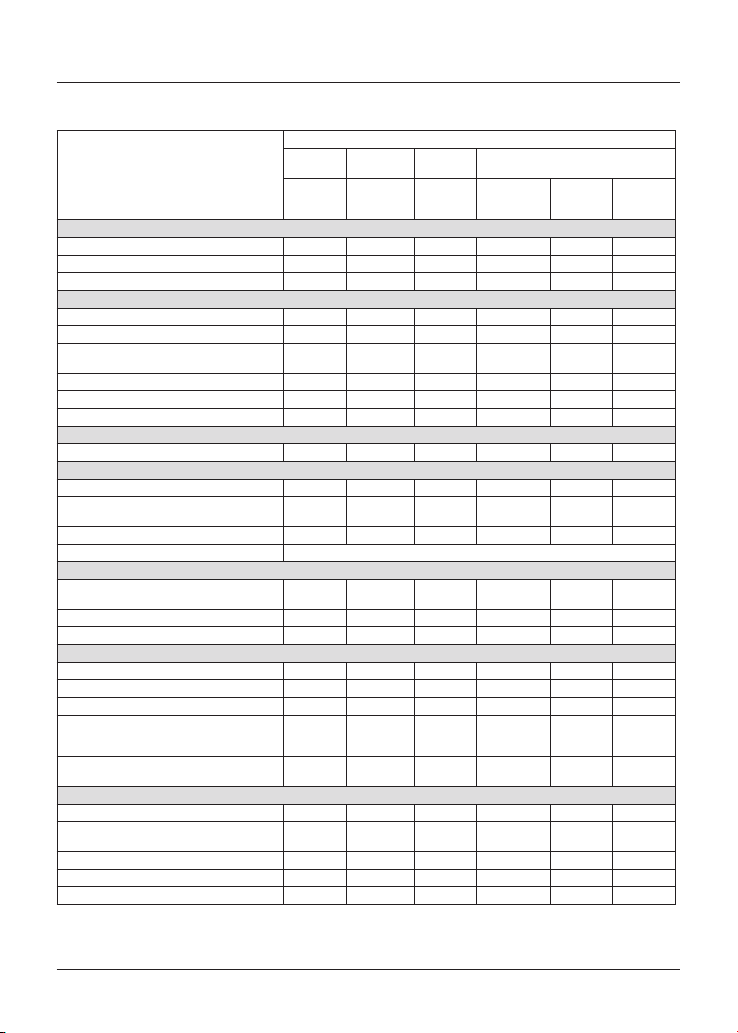
Maintenance and Adjustment
99
Scheduled Maintenance Table
Operation Description
Odometer Reading in Miles (Km) or Time Period, whichever comes first
First Service
Annual
Service
Mileage Based Service
Every
600 (1000)
6 Months
Ye ar
10,000 and
30,000 (16,000
and 48,000)
20,000
(32,000)
40,000
(64,000)
Lubrication
Engine - check for leaks Day • • • • •
Engine oil - renew - • • • • •
Engine oil filter - renew - • • • • •
Fuel System and Engine Management
Fuel system - check for leaks, chafing etc. - • • •
Throttle body plate (butterfly) - check/clean - • • •
Autoscan - Carry out a full Autoscan using the
Triumph Diagnostic Tool (print a customer copy)
- • • • • •
Air cleaner - renew - • • •
Fuel filter - renew - • •
Throttle bodies - balance - 1200 cc engines only - • • •
Ignition System
Spark plugs - renew - • •
Cooling System
Cooling system - check for leaks Day • • • • •
Cooling system - check hoses for chafing/
cracks/damage. Replace if necessary
- • • •
Coolant level - check/adjust Day • • • • •
Coolant - renew Every 3 years regardless of mileage
Engine
Clutch cable - check function and adjust as
necessary
Day • • • • •
Valve clearances - check - • •
Camshaft timing - • •
Wheels and Tyres
Tyre wear/tyre damage - check Day • • • • •
Tyre pressures - check/adjust Day • • • • •
Wheels - inspect for damage Day • • • • •
Wheels - check wheels for broken or damaged
spokes and check spoke tightness (models with
spoked wheels only)
Day • • • • •
Wheel bearings - check for wear/smooth
operation
- • • • • •
Steering and Suspension
Steering - check for free operation Day • • • • •
Front and rear suspension - check for damage/
leaks/smooth operation
Day • • • • •
Fork oil - renew - •
Headstock bearings - check/adjust - • • • • •
Headstock bearings - lubricate - • •
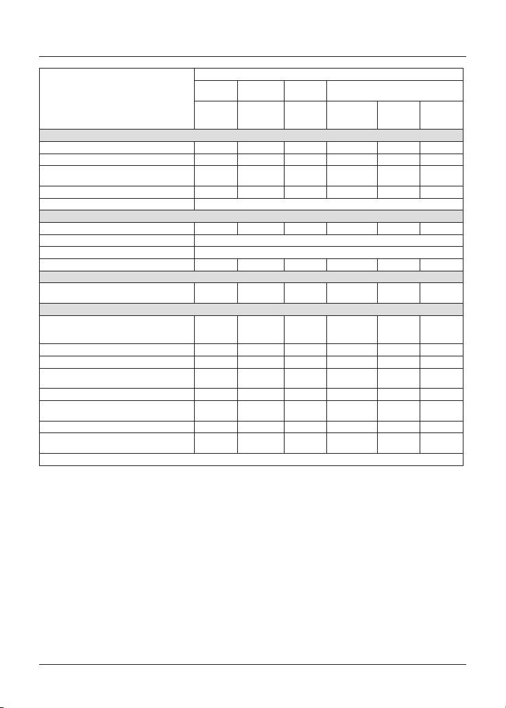
Maintenance and Adjustment
100
Operation Description
Odometer Reading in Miles (Km) or Time Period, whichever comes first
First Service
Annual
Service
Mileage Based Service
Every
600 (1000)
6 Months
Ye ar
10,000 and
30,000 (16,000
and 48,000)
20,000
(32,000)
40,000
(64,000)
Brakes
Brake pads - check wear levels Day • • • • •
Brake master cylinders - check for fluid leaks - • • • • •
Brake calipers - check for fluid leaks and seized
pistons
- • • • • •
Brake fluid levels - check Day • • • • •
Brake fluid - renew Every 2 years regardless of mileage
Drive Chain
Drive chain slack - check/adjust Day • • • • •
Drive chain - wear check Every 500 miles (800 km)
Drive chain - lubricate Every 200 miles (300 km)
Drive chain rubbing strip - check - • • • • •
Electrical
All lights, instruments and electrical systems
- check
Day • • • • •
General
Instruments and engine ECM - check for
latest calibration download using the Triumph
diagnostic tool
- • • • • •
Fasteners - inspect visually for security Day • • • • •
Bank angle indicators - inspect visually for wear Day • • • • •
Side stand/Centre stand - lubricate/check
operation
Day • • • • •
Side stand pivot pin - clean/grease - • • •
Carry out all outstanding Service Bulletin and
warranty work
- • • • • •
Carry out road test - • • • • •
Complete the service record book and reset the
service indicator (if fitted)
- • • • • •
* Evaporative system fitted to models for certain markets only.
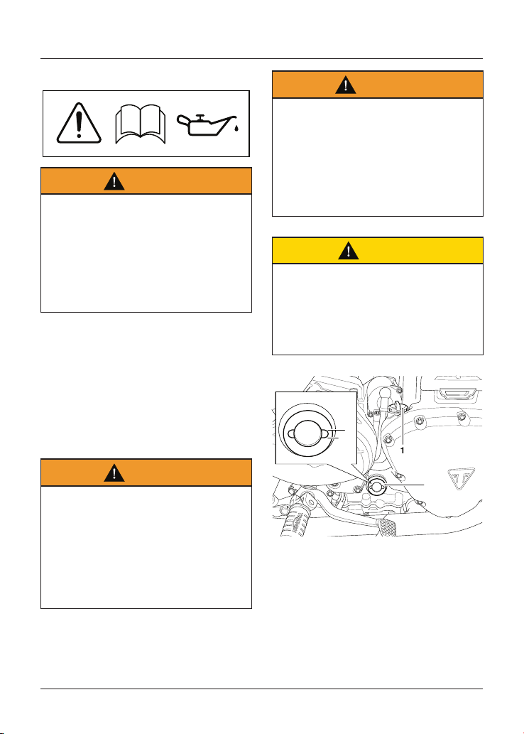
Maintenance and Adjustment
101
Engine Oil
Warning
Motorcycle operation with insufficient,
deteriorated, or contaminated engine
oil will cause accelerated engine
wear and may result in engine or
transmission seizure.
Seizure of the engine or transmission
may lead to sudden loss of motorcycle
control and an accident.
In order for the engine, transmission,
and clutch to function correctly,
maintain the engine oil at the correct
level, and change the engine oil and
oil filter in accordance with scheduled
maintenance requirements.
Engine Oil Level Inspection
Warning
Never start the engine or run the
engine in a confined area.
Exhaust fumes are poisonous and can
cause loss of consciousness and death
within a short period of time.
Always operate the motorcycle in the
open air or in an area with adequate
ventilation.
Warning
If the engine has recently been
running, the exhaust system will be
hot.
Before working on or near the exhaust
system, allow sufficient time for the
exhaust system to cool as touching
any part of a hot exhaust system
could cause burn injuries.
Caution
Running the engine with insufficient
engine oil will cause engine damage.
If the low oil pressure indicator
remains on, stop the engine
immediately and investigate the
situation.
3
4
2
1
1. Filler plug
2. Sight glass
3. Maximum limit
4. Minimum limit
Maintenance and Adjustment
102
To inspect the engine oil level:
• Start the engine and run at idle for
approximately five minutes. Stop the
engine and wait for at least three
minutes to allow the engine oil to
settle.
• Note the engine oil level visible in
the sight glass.
• When correct, engine oil should
be visible in the sight glass at a
point midway between the upper
(maximum) and lower (minimum)
markings on the sight glass.
Note
An accurate indication of the level of
engine oil in the engine is only shown
when the engine is at normal operating
temperature and the motorcycle is
upright (not on the side stand).
• If it is necessary to top up the
engine oil level, remove the filler
plug and add engine oil, a little at a
time, until the level registered in the
sight glass is correct.
Caution
Make sure no foreign matter or
contamination enters the engine
during an engine oil change or top up.
Contamination entering the engine
may lead to engine damage.
• Once the correct level is reached, fit
and tighten the filler plug.
Engine Oil and Oil Filter Change
Warning
Prolonged or repeated contact with
engine oil can lead to skin dryness,
irritation and dermatitis.
Used engine oil contains harmful
contamination that can lead to skin
cancer.
Always wear suitable protective
clothing and avoid skin contact with
used oil.
Warning
The oil may be hot to the touch.
Avoid contact with the hot oil by
wearing suitable protective clothing,
gloves, eye protection, etc.
Contact with hot oil may cause the
skin to be scalded or burned.
Warning
If the engine has recently been
running, the exhaust system will be
hot.
Before working on or near the exhaust
system, allow sufficient time for the
exhaust system to cool as touching
any part of a hot exhaust system
could cause burn injuries.
The engine oil and filter must be
renewed in accordance with scheduled
maintenance requirements.
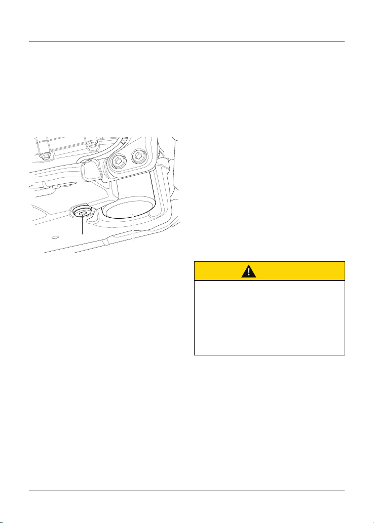
Maintenance and Adjustment
103
To change the engine oil and filter:
• Warm up the engine thoroughly
then stop the engine. Secure the
motorcycle on the side stand.
• Allow the engine oil to settle for five
minutes before draining.
• Place an oil drain pan beneath the
engine.
2
1
1. Sump plug
2. Engine oil filter
• Remove the sump plug from the
bottom of the sump and allow the
engine oil to drain.
• Secure the motorcycle in an upright
position on level ground.
• Position the oil drain pan beneath
the engine oil filter.
• Unscrew and remove the engine oil
filter using the Triumph service tool
T3880313. Dispose of the old filter in
an environmentally friendly way.
• Prefill the replacement engine oil
filter with new engine oil.
• Apply a smear of clean engine oil to
the sealing ring of the new engine
oil filter. Fit the engine oil filter and
tighten to 10 Nm.
• After the engine oil has completely
drained out, fit a new sealing
washer to the sump plug. Fit and
tighten the plug to 25 Nm.
• Remove the engine oil filler plug.
• Using a suitable funnel, fill the
engine with a 10W/40 or 10W/50
semi or fully synthetic motorcycle
engine oil that meets specification
API SH (or higher) and JASO MA,
such as Castrol Power 1 Racing 4T
10W-40 (fully synthetic) engine oil,
sold as Castrol Power RS Racing
4T 10W-40 (fully synthetic) in some
countries.
• Do not overfill or exceed the
capacities given in the Specifications
section.
• Start the engine and allow it to idle
for a minimum of 30 seconds.
Caution
Raising the engine speed above idle,
before the engine oil reaches all
parts of the engine can cause engine
damage or seizure.
Only raise engine speed after running
the engine for 30 seconds to allow the
engine oil to circulate fully.
• Make sure that the low oil pressure
warning light extinguishes shortly
after starting.
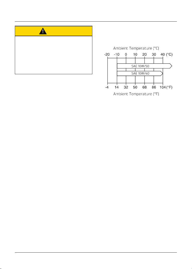
Maintenance and Adjustment
104
Caution
If the engine oil pressure is too low,
the low oil pressure warning light will
illuminate. If this light stays on when
the engine is running, stop the engine
immediately and investigate the cause.
Running the engine with low oil
pressure will cause engine damage.
• Turn the ignition OFF, check the
engine oil level using the method
previously described, and top up
to between the minimum and
maximum level lines in the sight
glass.
Disposal of Used Engine Oil and Oil
Filters
To protect the environment, do not
pour oil on the ground, down sewers
or drains, or into watercourses. Do not
place used oil filters in with general
waste. If in doubt, contact your local
authority.
Engine Oil Specification and Grade
Triumph's high performance fuel
injected engines are designed to
use 10W/40 or 10W/50 semi or fully
synthetic motorcycle engine oil that
meets specification API SH (or higher)
and JASO MA, such as Castrol Power
1 Racing 4T 10W-40 (fully synthetic)
engine oil, sold as Castrol Power RS
Racing 4T 10W-40 (fully synthetic) in
some countries.
Refer to the chart below for the correct
oil viscosity (10W/40 or 10W/50) to be
used in your riding area.
Oil Viscosity Temperature Range
Do not add any chemical additives
to the engine oil. The engine oil also
lubricates the clutch and any additives
could cause the clutch to slip.
Do not use mineral, vegetable, non-
detergent oil, castor based oils or any
oil not conforming to the required
specification. The use of these oils may
cause instant, severe engine damage.
Make sure that no foreign matter enters
the crankcase during an engine oil
change or top up.
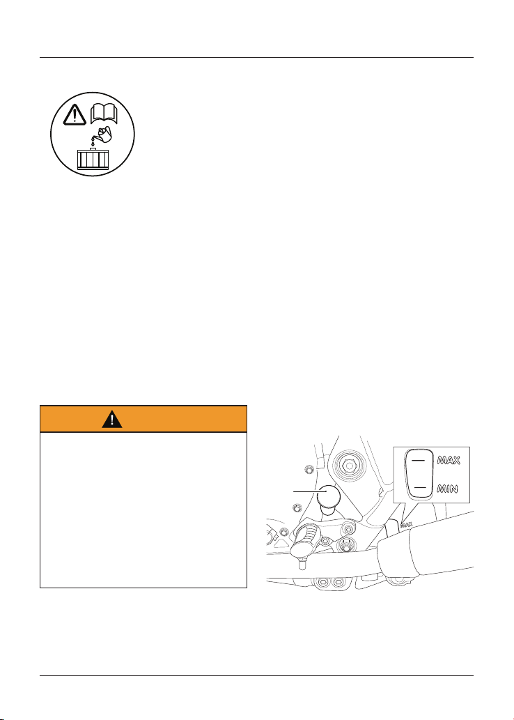
Maintenance and Adjustment
105
Cooling System
To ensure efficient engine cooling, check
the coolant level each day before riding
the motorcycle, and top up the coolant
if the level is low.
Note
A year round, Hybrid Organic Acid
Technology (known as Hybrid OAT or
HOAT) coolant is installed in the cooling
system when the motorcycle leaves the
factory. It is coloured green, contains a
50% solution of ethylene glycol based
antifreeze, and has a freezing point of
-35°C (-31°F).
Corrosion Inhibitors
Warning
HD4X Hybrid OAT coolant contains
corrosion inhibitors and antifreeze
suitable for aluminium engines and
radiators. Always use the coolant in
accordance with the instructions of
the manufacturer.
Coolant that contains anti-freeze and
corrosion inhibitors contains toxic
chemicals that are harmful to the
human body. Never swallow antifreeze
or any of the motorcycle coolant.
Note
HD4X Hybrid OAT coolant, as supplied by
Triumph, is premixed and does not need
to be diluted prior to filling or topping up
the cooling system.
To protect the cooling system from
corrosion, the use of corrosion inhibitor
chemicals in the coolant is essential.
If coolant containing a corrosion
inhibitor is not used, the cooling system
will accumulate rust and scale in the
water jacket and radiator. This will block
the coolant passages, and considerably
reduce the efficiency of the cooling
system.
Coolant Level Inspection
Note
The coolant level should be checked
when the engine is cold (at room or
ambient temperature).
Bonneville T100 (all models),
Bonneville T120 (all models) and
Street Twin
1
2
1. Expansion tank cap
2. MAX and MIN marks
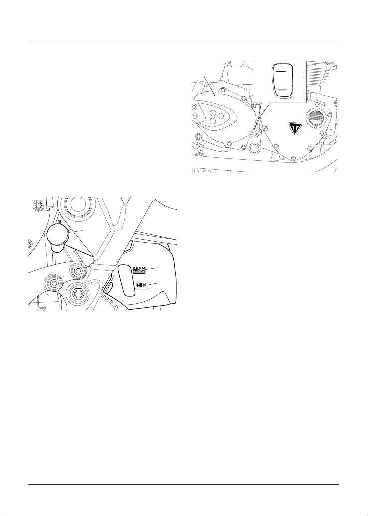
Maintenance and Adjustment
106
To inspect the coolant level:
• Position the motorcycle on level
ground and in an upright position.
The expansion tank can be viewed
from the left hand side of the
motorcycle, towards the rear of the
engine.
• Check the coolant level in the
expansion tank. The coolant level
must be between the MAX and MIN
marks. If the coolant is below the
minimum level, the coolant level
must be adjusted.
Street Scrambler
cjyr
3
1
2
1. Expansion tank cap
2. MAX mark
3. MIN mark
To inspect the coolant level:
• Position the motorcycle on level
ground and in an upright position.
The expansion tank can be viewed
from the left hand side of the
motorcycle, towards the rear of the
engine.
• Check the coolant level in the
expansion tank. The coolant level
must be between the MAX and MIN
marks. If the coolant is below the
minimum level, the coolant level
must be adjusted.
Speed Twin and Thruxton RS
2
1
1. Expansion tank cap
2. MAX and MIN marks
To inspect the coolant level:
• Position the motorcycle on level
ground and in an upright position.
The expansion tank can be viewed
from the right hand side of the
motorcycle, towards the rear of the
engine.
• Check the coolant level in the
expansion tank. The coolant level
must be between the maximum (top)
and minimum (bottom) marks. If the
coolant is below the minimum level,
the coolant level must be adjusted.
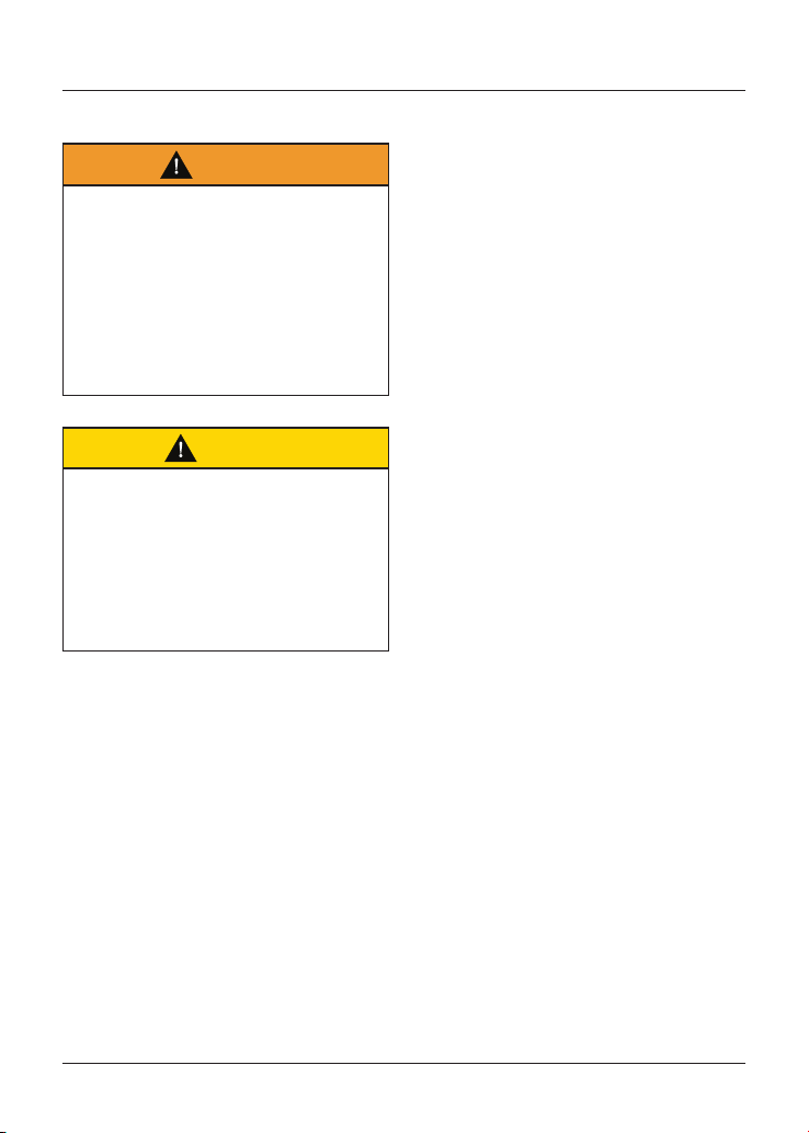
Maintenance and Adjustment
107
Coolant Level Adjustment
Warning
Do not remove the expansion tank or
radiator pressure cap when the engine
is hot.
When the engine is hot, the coolant
inside the radiator will be hot and also
under pressure.
Contact with this hot, pressurised
coolant will cause scalds and skin
damage.
Caution
If hard water is used in the
cooling system, it will cause scale
accumulation in the engine and
radiator and considerably reduce the
efficiency of the cooling system.
Reduced cooling system efficiency
may cause the engine to overheat and
suffer severe damage.
Note
If the coolant level is being checked
because the coolant has overheated,
also check the level in the radiator and
top up if necessary.
In an emergency, distilled water can be
added to the cooling system. However,
the coolant must then be drained and
replenished with HD4X Hybrid OAT
coolant as soon as possible.
Bonneville T100 (all models),
Bonneville T120 (all models),
Street Scrambler and Street Twin
To adjust the coolant level:
• Allow the engine to cool.
• The expansion tank cap can be
removed from the left hand side of
the motorcycle, towards the rear of
the engine.
• Remove the cap from the expansion
tank and add coolant mixture
through the filler opening until the
level reaches the MAX mark. Refit
the cap.
Speed Twin and Thruxton RS
To adjust the coolant level:
• The expansion tank cap can be
removed from the right hand side of
the motorcycle, towards the rear of
the engine.
• Remove the sprocket cover.
• Remove the cap from the expansion
tank and add coolant mixture
through the filler opening until the
level reaches the maximum (top)
mark.
• Refit the cap. Refit the sprocket
cover to 9 Nm.
Coolant Change
It is recommended that the coolant
is changed by an authorised Triumph
dealer in accordance with scheduled
maintenance requirements.
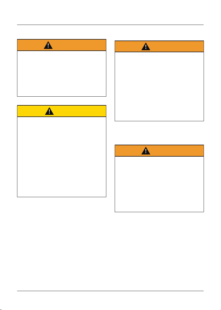
Maintenance and Adjustment
108
Radiator and Hoses
Warning
The fan operates automatically when
the engine is running.
Always keep hands and clothing away
from the fan.
Contact with the rotating fan may
cause an accident and/or personal
injury.
Caution
Using high pressure water sprays,
such as from a car wash facility or
household pressure washer, can
damage the radiator fins, cause leaks
and impair the radiator's efficiency.
Do not obstruct or deflect airflow
through the radiator by installing
unauthorised accessories, either in
front of the radiator or behind the
cooling fan.
Interference with the radiator airflow
can cause overheating, potentially
resulting in engine damage.
Check the radiator hoses for cracks
or deterioration, and tension clips for
tightness in accordance with scheduled
maintenance requirements. Have your
authorised Triumph dealer replace any
defective items.
Check the radiator grille and fins for
obstructions by insects, leaves or
mud. Clean off any obstructions with a
stream of low pressure water.
Throttle Control
Warning
Always be alert for changes in the
'feel' of the throttle control and have
the throttle system checked by an
authorised Triumph dealer if any
changes are detected.
Changes can be due to wear in the
mechanism, which could lead to a
sticking throttle control.
A sticking or stuck throttle control will
lead to loss of motorcycle control and
an accident.
Throttle Inspection
Warning
Use of the motorcycle with a sticking
or damaged throttle control will
interfere with the throttle function
resulting in loss of motorcycle control
and an accident.
To avoid continued use of a sticking or
damaged throttle control, always have
it checked by your authorised Triumph
dealer.
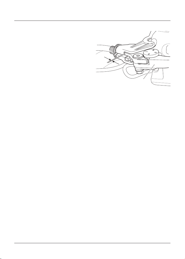
Maintenance and Adjustment
109
To inspect the throttle:
• Check that the throttle opens
smoothly, without undue force
and that it closes without sticking.
Have your authorised Triumph
dealer check the throttle system if
a problem is detected or any doubt
exists.
• If there is an incorrect amount of
free play, Triumph recommends that
you have your authorised Triumph
dealer investigate.
• Check that there is 1 - 2 mm of
throttle grip free play when lightly
turning the throttle grip back and
forth.
Clutch
2
1
1. Clutch lever
2. 2 - 3 mm
The motorcycle is equipped with a
cable-operated clutch.
If the clutch lever has excessive free
play, the clutch may not disengage fully.
This will cause difficulty in changing
gear and selecting neutral. This may
cause the engine to stall and make the
motorcycle difficult to control.
Conversely, if the clutch lever has
insufficient free play the clutch may
not engage fully, causing the clutch to
slip, which will reduce performance and
cause premature clutch wear.
Clutch lever free play must be
checked in accordance with scheduled
maintenance requirements.
Clutch Inspection
Check that there is 2 - 3 mm clutch
lever free play at the lever.
If there is an incorrect amount of free
play, adjustments must be made.
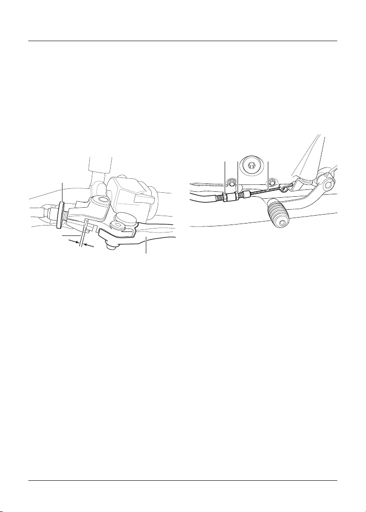
Maintenance and Adjustment
110
Clutch Adjustment
To adjust the clutch:
• Turn the adjuster sleeve until the
correct amount of clutch lever free
play is achieved.
• Check that there is 2 - 3 mm clutch
lever free play at the lever.
• If there is an incorrect amount of
free play, adjustments must be
made.
3
2 - 3 mm
1
2
1. Adjuster sleeve (locknut fully released)
2. Correct clearance 2-3 mm
3. Clutch lever
If correct adjustment cannot be made
using the lever adjuster, use the cable
adjuster at the lower end of the cable.
• Loosen the adjuster lock nut.
• Turn the outer cable adjuster to give
2 - 3 mm of free play at the clutch
lever.
• Tighten the lock nut to 3.5 Nm.
312
1. Adjuster nut
2. Lock nut
3. Clutch cable
Maintenance and Adjustment
111
Drive Chain
Warning
A loose or worn chain, or a chain that
breaks or jumps off the sprockets
could catch on the engine sprocket or
lock the rear wheel.
A chain that snags on the engine
sprocket will injure the rider and lead
to loss of motorcycle control and an
accident.
Similarly, locking the rear wheel will
lead to loss of motorcycle control and
an accident.
For safety and to prevent excessive
wear the drive chain must be checked,
adjusted and lubricated in accordance
with the scheduled maintenance
requirements. Checking, adjustment and
lubrication must be carried out more
frequently for extreme conditions such
as high speed riding, salty or heavily
gritted roads.
If the chain is badly worn or incorrectly
adjusted (either too loose or too tight)
the chain could jump off the sprockets
or break. Therefore, always replace
worn or damaged chains using genuine
Triumph parts supplied by an authorised
Triumph dealer.
Drive Chain Lubrication
Lubrication is necessary every 200 miles
(300 km) and also after riding in wet
weather, on wet roads, or any time that
the chain appears dry.
To lubricate the drive chain:
• Use the special drive chain
lubricant as recommended in the
Specifications section.
• Apply lubricant to the sides of the
rollers then allow the motorcycle
to stand unused for at least eight
hours (overnight is ideal). This will
allow the lubricant to penetrate to
the drive chain O-rings etc.
• Before riding, wipe off any excess
lubricant.
• If the drive chain is especially dirty,
clean first and then apply lubricant
as mentioned above.
Caution
Do not use a pressure washer to
clean the drive chain as this may
cause damage to the drive chain
components.
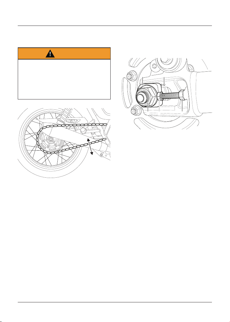
Maintenance and Adjustment
112
Drive Chain Free Movement
Inspection
Warning
Before starting work, make sure
the motorcycle is stabilised and
adequately supported.
This will help prevent it from falling
and causing personal injury and/or
damage to the motorcycle.
1
1. Maximum movement position
To inspect the drive chain free
movement:
• Place the motorcycle on a level
surface and hold it in an upright
position with no weight on it.
• Rotate the rear wheel by pushing
the motorcycle to find the position
where the drive chain is tightest,
and measure the vertical movement
of the drive chain midway between
the sprockets.
Drive Chain Free Movement
Adjustment
The vertical movement of the drive
chain must be in the range 20 - 30 mm.
45
1 2 3
1. Rear wheel spindle nut
2. Adjuster bolt
3. Adjuster bolt lock nut
4. Adjuster markings
5. Spindle adjuster
If the drive chain free movement
measurement is incorrect, adjustments
must be made as follows:
• Loosen the wheel spindle nut.
• Loosen the lock nuts on both the
left hand and right hand drive chain
adjuster bolts.
• Move both adjusters by an equal
amount using the adjuster markings
as a guideline.
• Turn the adjuster bolts clockwise to
increase drive chain free movement
and anticlockwise to reduce drive
chain free movement.
• When the correct amount of drive
chain free movement has been set,
push the wheel into firm contact
with the adjusters.
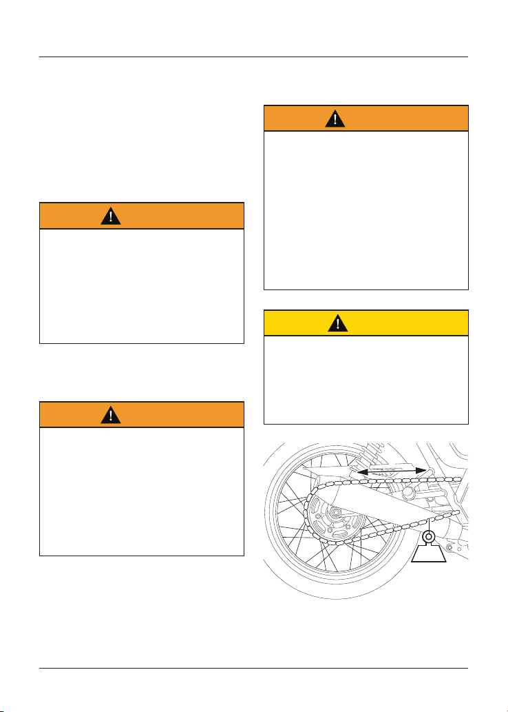
Maintenance and Adjustment
113
• Make sure the same adjuster
marking is aligned with the spindle
adjuster on both sides of the
swinging arm.
• Tighten both adjuster lock nuts to
20 Nm and the rear wheel spindle
nut to 110 Nm.
• Repeat the drive chain adjustment
check. Readjust if necessary.
Warning
Operation of the motorcycle with
insecure adjuster lock nuts or a
loose wheel spindle may result in
impaired stability and handling of the
motorcycle.
This impaired stability and handling
may lead to loss of control or an
accident.
• Check the rear brake effectiveness.
Rectify if necessary.
Warning
It is dangerous to operate the
motorcycle with defective brakes; you
must have your authorised Triumph
dealer take remedial action before you
attempt to ride the motorcycle again.
Failure to take remedial action may
reduce braking efficiency leading
to loss of motorcycle control or an
accident.
Drive Chain and Sprocket Wear
Inspection
Warning
Never neglect drive chain maintenance
and always have drive chains installed
by an authorised Triumph dealer.
Use a genuine Triumph supplied drive
chain as specified in the Triumph Parts
Catalogue.
The use of non-approved drive chains
may result in a broken drive chain or
may cause the drive chain to jump
off the sprockets leading to loss of
motorcycle control or an accident.
Caution
If the sprockets are found to be worn,
always replace the sprockets and drive
chain together.
Replacing worn sprockets without also
replacing the drive chain will lead to
premature wear of the new sprockets.
10-20
KG
2
1
1. Measure across 20 links
2. Weight
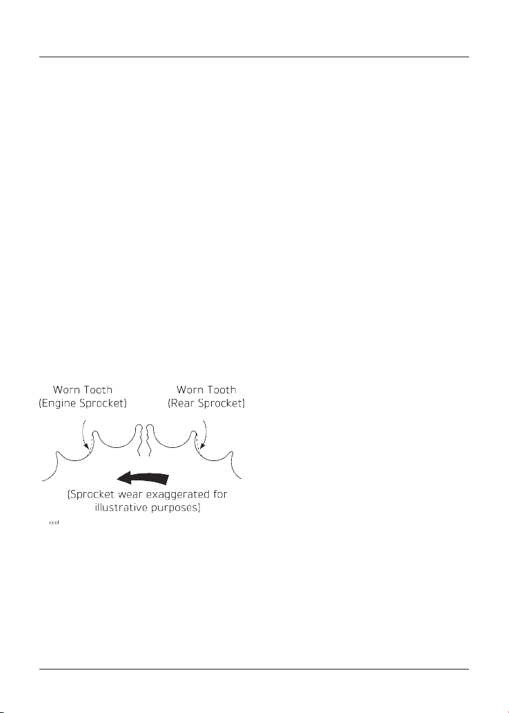
Maintenance and Adjustment
114
To inspect the drive chain and sprocket
wear:
• Remove the drive chain guard.
• Stretch the drive chain taut by
hanging a 10 - 20 kg (20 - 40 lb)
weight on the drive chain.
• Measure the length of 20 links on
the straight part of the drive chain
from pin centre of the 1st pin to the
pin centre of the 21st pin. Since the
drive chain may wear unevenly, take
measurements in several places.
• If the length exceeds the maximum
service limit of 320 mm, the drive
chain must be replaced.
• Rotate the rear wheel and inspect
the drive chain for damaged rollers,
and loose pins and links.
• Also inspect the sprockets for
unevenly or excessively worn or
damaged teeth.
Note
The illustration shows wear on
sprockets mounted on the left hand side
of the motorcycle.
For sprockets mounted on the right
hand side of the motorcycle, the wear is
on the opposite side of the tooth.
• If there is any irregularity, have the
drive chain and/or the sprockets
replaced by an authorised Triumph
dealer.
• Refit the drive chain guard and
tighten the fixings to 9 Nm.
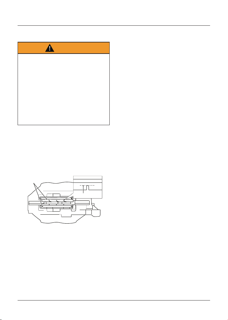
Maintenance and Adjustment
115
Brakes
Warning
Brake pads must always be replaced
as a wheel set. At the front, where two
calipers are fitted on the same wheel,
replace all the brake pads in both
calipers.
Replacing individual pads will reduce
braking efficiency and may cause an
accident.
After replacement brake pads have
been fitted, ride with extreme caution
until the new pads have 'broken in'.
Brake pads must be inspected
in accordance with scheduled
maintenance requirements and replaced
if worn to, or beyond the minimum
service thickness.
1
2
1. Brake pads
2. Minimum thickness line
Bonneville T100 (all models) and
Bonneville T120 (all models)
If the lining thickness of any brake
pad (front or rear brakes) is less than
1.5 mm (0.06 in), that is, if the brake pad
has worn down to the bottom of the
grooves, replace all the brake pads on
that wheel.
Street Scrambler, Speed Twin,
Street Twin and Thruxton RS
If the lining thickness of any brake pad
is less than 1.0 mm (0.04 in) (front) or
1.5 mm (0.06 in) (rear), replace all the
brake pads on that wheel.
Note
Street Scrambler, Speed Twin and
Street Twin Only
An area of the front brake backing
plate is raised and will cause the front
brake to squeal as notification to the
rider when the brake pad(s) are below
the minimum thickness. Replace all the
brake pads on that wheel.
Maintenance and Adjustment
116
Breaking-in New Brake Pads and
Discs
Warning
Brake pads must always be replaced
as a wheel set. At the front, where two
calipers are fitted on the same wheel,
replace all the brake pads in both
calipers.
Replacing individual pads will reduce
braking efficiency and may cause an
accident.
After replacement brake pads have
been fitted, ride with extreme caution
until the new pads have 'broken in'.
New brake discs and pads require
a period of careful breaking-in that
will optimise the performance and
longevity of the discs and pads. The
recommended distance for breaking-
in new pads and discs is 200 miles
(300 km).
During this period, avoid extreme
braking, ride with caution and allow for
greater braking distances.
Brake Pad Wear Compensation
Warning
If the brake lever or pedal feels soft
when it is applied, or if the lever/pedal
travel becomes excessive, there may
be air in the brake pipes and hoses or
the brakes may be defective.
It is dangerous to operate the
motorcycle under such conditions and
your authorised Triumph dealer must
rectify the fault before riding.
Riding with defective brakes may lead
to loss of motorcycle control and an
accident.
Disc and brake pad wear is
automatically compensated for and has
no effect on the brake lever or pedal
action. There are no parts that require
adjustment on the front and rear
brakes.
Maintenance and Adjustment
117
Disc Brake Fluid
Warning
Brake fluid is hygroscopic which
means it will absorb moisture from the
air.
Any absorbed moisture will greatly
reduce the boiling point of the brake
fluid causing a reduction in braking
efficiency.
Because of this, always replace brake
fluid in accordance with scheduled
maintenance requirements.
Always use new brake fluid from a
sealed container and never use fluid
from an unsealed container or from
one which has been previously opened.
Do not mix different brands or grades
of brake fluid.
Check for fluid leakage around brake
fittings, seals and joints and also
check the brake hoses for splits,
deterioration and damage.
Always rectify any faults before riding.
Failure to observe and act upon any
of these items may cause a dangerous
riding condition leading to loss of
control and an accident.
Warning
If the ABS is not functioning, the brake
system will continue to function as a
non-ABS equipped brake system.
In this situation, braking too hard will
cause the wheels to lock resulting in
loss of control and an accident.
Reduce speed and do not continue to
ride for longer than is necessary with
the indicator light illuminated. Contact
an authorised Triumph dealer as soon
as possible to have the fault checked
and rectified.
Inspect the level of brake fluid in
both reservoirs and change the brake
fluid in accordance with scheduled
maintenance requirements. Use only
DOT 4 fluid as recommended in the
Specification section. The brake fluid
must also be changed if it becomes,
or is suspected of having become
contaminated with moisture or any
other contaminants.
Note
A special tool is required to bleed the
ABS braking system. Contact your
authorised Triumph dealer when the
brake fluid needs renewing or the
hydraulic system requires maintenance.
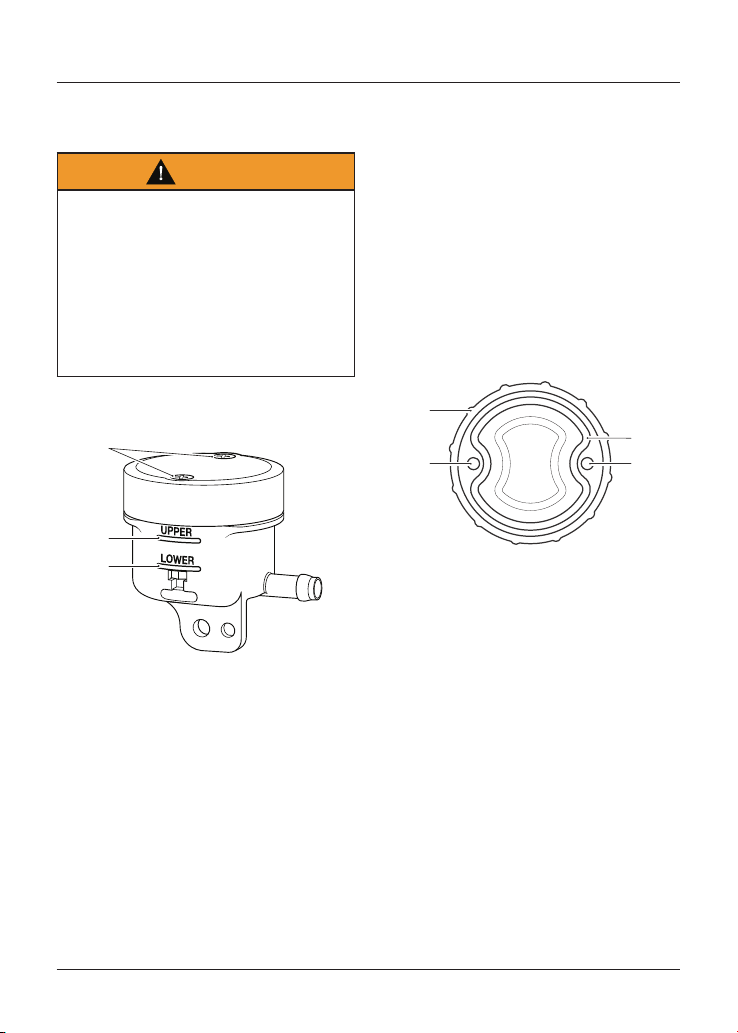
Maintenance and Adjustment
118
Front Brake Fluid Level Inspection
and Adjustment
Warning
If there has been an appreciable drop
in the level of the fluid in either fluid
reservoir, consult your authorised
Triumph dealer for advice before riding.
Riding with depleted brake fluid levels,
or with a brake fluid leak is dangerous
and will cause reduced brake
performance potentially leading to loss
of motorcycle control and an accident.
Street Scrambler and Street Twin
2
1
3
1. Reservoir cap retaining screws
2. UPPER level line
3. LOWER level line
To inspect the front brake fluid level:
• Check the level of brake fluid visible
in the UPPER and LOWER section of
the reservoir.
• The brake fluid level in the reservoir
must be kept between the UPPER
and LOWER level lines (reservoir
held horizontal).
To adjust the front brake fluid level:
• Release the reservoir cap retaining
screws and remove the reservoir
cap and the diaphragm seal.
• Fill the reservoir to the UPPER level
line using new DOT 4 brake fluid
from a sealed container.
• Fit the diaphragm seal into the
reservoir cap and make sure that
the holes for the fixings in the
reservoir cap and the diaphragm
seal are correctly aligned.
1
2
33
1. Reservoir cap
2. Diaphragm seal
3. Reservoir cap retaining screw holes
• Install the reservoir cap retaining
screws into the reservoir cap and
diaphragm seal assembly.
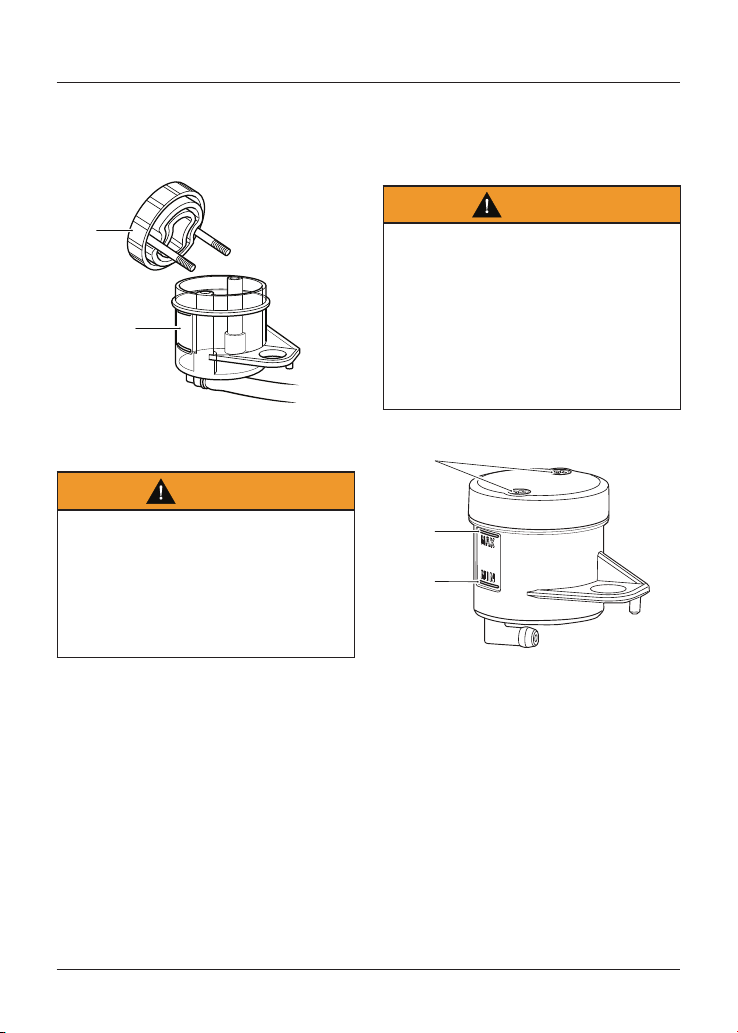
Maintenance and Adjustment
119
• Hold the assembly together
and position the reservoir cap,
diaphragm seal and reservoir cap
retaining screws onto the reservoir.
1
2
1. Reservoir cap, diaphragm seal and
reservoir cap retaining screws assembly
2. Reservoir
Warning
If the reservoir cap retaining screws
are over tightened this can result in a
brake fluid leak.
A dangerous riding condition leading
to loss of motorcycle control and an
accident could result if this warning is
ignored.
• Tighten the reservoir cap retaining
screws to 1 Nm.
Front Brake Fluid Level Inspection
and Adjustment
Speed Twin and Thruxton RS
Warning
If there has been an appreciable drop
in the level of the fluid in either fluid
reservoir, consult your authorised
Triumph dealer for advice before riding.
Riding with depleted brake fluid levels,
or with a brake fluid leak is dangerous
and will cause reduced brake
performance potentially leading to loss
of motorcycle control and an accident.
3
1
2
1. Reservoir cap retaining screws
2. MAX level line
3. MIN level line
To inspect the front brake fluid level:
• Check the level of brake fluid visible
in the MAX and MIN section of the
reservoir.
• The brake fluid level in the reservoir
must be kept between the MAX
and MIN level lines (reservoir held
horizontal).
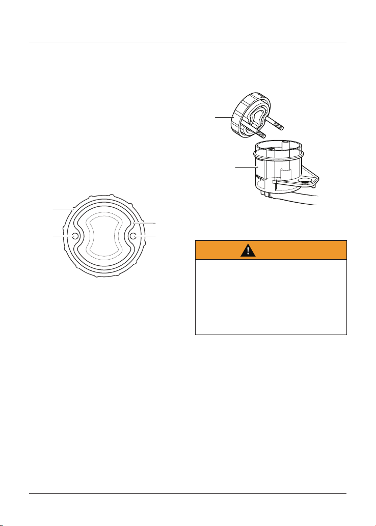
Maintenance and Adjustment
120
To adjust the front brake fluid level:
• Release the reservoir cap retaining
screws and remove the reservoir
cap and the diaphragm seal.
• Fill the reservoir to the MAX level
line using new DOT 4 brake fluid
from a sealed container.
• Fit the diaphragm seal into the
reservoir cap and make sure that
the holes for the fixings in the
reservoir cap and the diaphragm
seal are correctly aligned.
1
2
33
1. Reservoir cap
2. Diaphragm seal
3. Reservoir cap retaining screw holes
• Install the reservoir cap retaining
screws into the reservoir cap and
diaphragm seal assembly.
• Hold the assembly together
and position the reservoir cap,
diaphragm seal and reservoir cap
retaining screws onto the reservoir.
1
2
1. Reservoir cap, diaphragm seal and
reservoir cap retaining screws assembly
2. Reservoir
Warning
If the reservoir cap retaining screws
are over tightened this can result in a
brake fluid leak.
A dangerous riding condition leading
to loss of motorcycle control and an
accident could result if this warning is
ignored.
• Tighten the reservoir cap retaining
screws to 1 Nm.
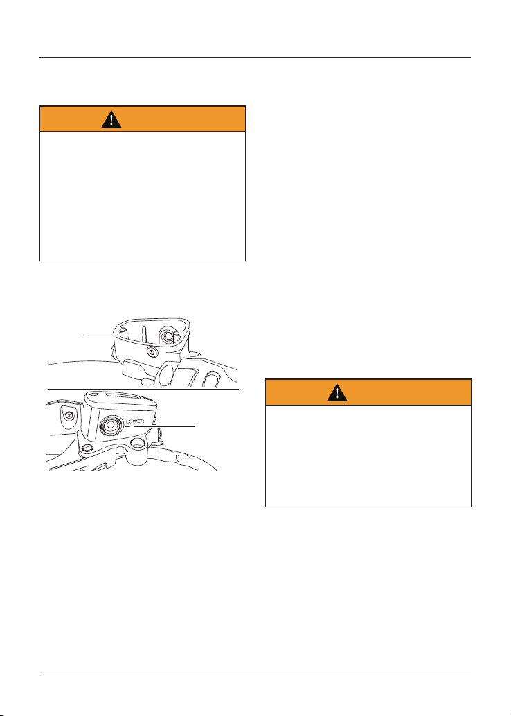
Maintenance and Adjustment
121
Front Brake Fluid Level Inspection
and Adjustment
Warning
If there has been an appreciable drop
in the level of the fluid in either fluid
reservoir, consult your authorised
Triumph dealer for advice before riding.
Riding with depleted brake fluid levels,
or with a brake fluid leak is dangerous
and will cause reduced brake
performance potentially leading to loss
of motorcycle control and an accident.
Bonneville T100 (all models) and
Bonneville T120 (all models)
1
2
1. Upper level line
2. Lower level line
To inspect the front brake fluid level:
• Check the level of fluid visible in the
window at the front of the reservoir
body.
• The brake fluid level must be kept
between the upper and lower level
lines (reservoir held horizontal).
To adjust the front brake fluid level:
• Release the reservoir cap retaining
screws and remove the reservoir
cap and the diaphragm seal.
• Fill the reservoir to the upper level
line using new DOT 4 brake fluid
from a sealed container.
• Fit the diaphragm seal into the
reservoir cap and make sure that
the holes for the fixings in the
reservoir cap and the diaphragm
seal are correctly aligned.
• Install the reservoir cap retaining
screws into the reservoir cap and
diaphragm seal assembly.
• Hold the assembly together
and position the reservoir cap,
diaphragm seal and reservoir cap
retaining screws onto the reservoir.
• Tighten the reservoir cap retaining
screws to 1 Nm.
Warning
If the reservoir cap retaining screws
are over tightened this can result in a
brake fluid leak.
A dangerous riding condition leading
to loss of motorcycle control and an
accident could result if this warning is
ignored.
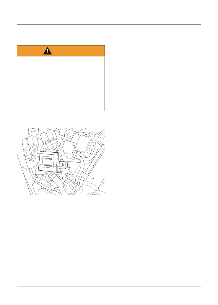
Maintenance and Adjustment
122
Rear Brake Fluid Level Inspection
and Adjustment
Warning
If there has been an appreciable drop
in the level of the fluid in either fluid
reservoir, consult your authorised
Triumph dealer for advice before riding.
Riding with depleted brake fluid levels,
or with a brake fluid leak is dangerous
and will cause reduced brake
performance potentially leading to loss
of motorcycle control and an accident.
All Models except Street Scrambler
citi_1
1
2
1. Upper level line
2. Lower level line
To inspect the rear brake fluid level:
• Remove the right hand side panel as
described on page 67.
• The brake fluid level in the rear
reservoir must be kept between the
UPPER and LOWER level lines.
To adjust the rear brake fluid level:
• Release the reservoir from the
airbox without detaching the
connecting hose.
• Release the reservoir cap retaining
screws and remove the reservoir
cap noting the position of the
diaphragm seal.
• Fill the reservoir to the UPPER level
line using new DOT 4 brake fluid
from a sealed container.
• Fit the diaphragm seal into the
reservoir cap and make sure that
the holes for the fixings in the
reservoir cap and the diaphragm
seal are correctly aligned.
• Install the reservoir cap retaining
screws into the reservoir cap and
diaphragm seal assembly.
• Hold the assembly together
and position the reservoir cap,
diaphragm seal and reservoir cap
retaining screws onto the reservoir.
• Tighten the reservoir cap retaining
screws to 1.5 Nm.
• Refit the reservoir to the airbox
by tightening the original fixing to
5 Nm.
• Refit the right hand side panel.
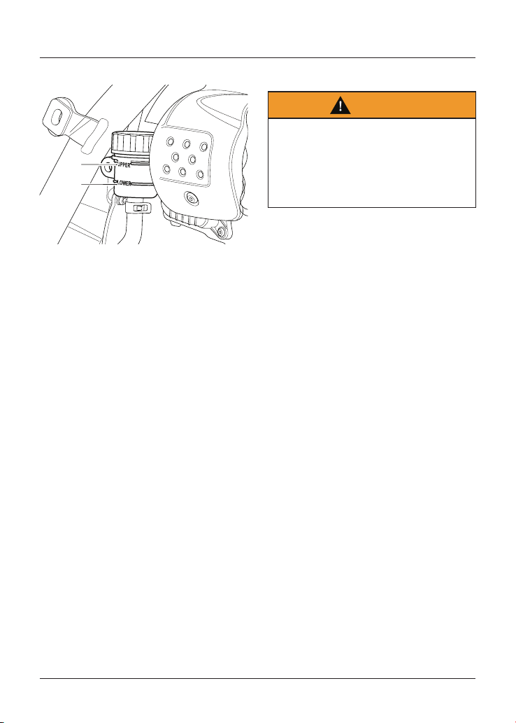
Maintenance and Adjustment
123
Street Scrambler
cjyu
1
2
1. Upper level line
2. Lower level line
To inspect the rear brake fluid level:
• Remove the right hand side panel as
described for the Street Scrambler
on page 68.
• The brake fluid level in the rear
reservoir must be kept between the
upper and lower level lines.
To adjust the rear brake fluid level:
• Release the reservoir from the
frame without detaching the
connecting hose.
• Remove the reservoir cap noting the
position of the sealing diaphragm.
• Fill the reservoir to the upper level
line using new DOT 4 brake fluid
from a sealed container.
• Refit the reservoir cap making sure
that the diaphragm seal is correctly
positioned between the reservoir
cap and the reservoir body.
• Refit the reservoir to the frame by
tightening the original fixing to
5 Nm.
• Refit the right hand side panel.
Brake Light Switches
Warning
Riding the motorcycle with defective
brake lights is illegal and dangerous.
An accident causing injury to the rider
and other road users may result from
use of a motorcycle with defective
brake lights.
The brake light is activated
independently by either the front or
rear brake. If, with the ignition in the ON
position, the brake light does not work
when the front brake lever is pulled
or the rear brake pedal is pressed,
have your authorised Triumph dealer
investigate and rectify the fault.
Maintenance and Adjustment
124
Mirrors
Warning
Operation of the motorcycle with
incorrectly adjusted mirrors is
dangerous.
Operation of the motorcycle with
incorrectly adjusted mirrors will result
in loss of vision to the rear of the
motorcycle. It is dangerous to ride a
motorcycle without sufficient rearward
vision.
Always adjust the mirrors to provide
sufficient rearward vision before riding
the motorcycle.
Warning
Never attempt to clean or adjust
mirrors while riding the motorcycle.
Removal of the rider’s hands from the
handlebars while riding the motorcycle
will diminish the ability of the rider to
maintain control of the motorcycle.
Attempting to clean or adjust mirrors
while riding the motorcycle may result
in loss of control of the motorcycle
and an accident.
Only attempt to clean or adjust the
mirrors while stationary.
Models with Bar End Mirrors
Warning
Incorrect adjustment of the bar end
mirrors may cause the mirror arm
to contact the fuel tank, brake or
clutch levers or other parts of the
motorcycle.
This will restrict brake or clutch
lever operation or restrict steering
movement, resulting in loss of
motorcycle control and an accident.
Adjust the mirrors as required to make
sure they do not contact any part of
the motorcycle. After adjustment,
move the handlebar to the left and
right full lock while checking that the
mirrors do not contact the fuel tank,
brake or clutch levers or other parts of
the motorcycle.
Caution
Incorrect adjustment of the bar end
mirrors may cause the mirror arm
to contact the fuel tank, brake or
clutch levers or other parts of the
motorcycle.
This will result in damage to the fuel
tank, brake or clutch levers or other
parts of the motorcycle.
Adjust the mirrors as required to make
sure they do not contact any part of
the motorcycle. After adjustment,
move the handlebar to the left and
right full lock while checking that the
mirrors do not contact the fuel tank,
brake or clutch levers or other parts of
the motorcycle.
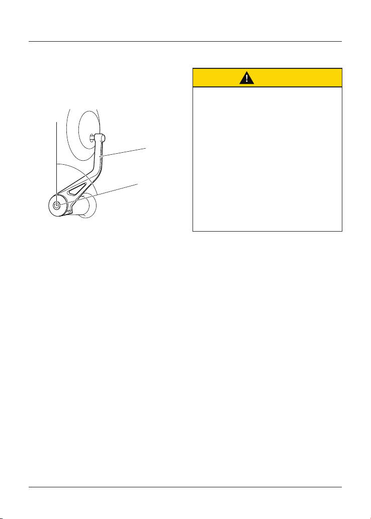
Maintenance and Adjustment
125
The bar end mirrors will be set by your
authorised Triumph dealer and will not
normally require any adjustment. Should
adjustment be necessary, do not rotate
the mirror beyond 75°, measured from
the vertical section of the mirror arm.
75°
1
1. Mirror arm vertical section
Steering/Wheel Bearings
Caution
To prevent risk of injury from
the motorcycle falling during the
inspection, make sure that the
motorcycle is stabilised and secured
on a suitable support.
Do not exert extreme force against
each wheel or rock each wheel
vigorously as this may cause the
motorcycle to become unstable
and cause injury by falling from its
support.
Make sure that the position of the
support block will not cause damage to
the motorcycle.
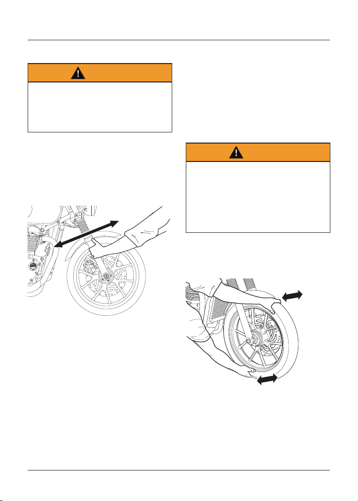
Maintenance and Adjustment
126
Steering Inspection
Warning
Riding the motorcycle with incorrectly
adjusted or defective steering
(headstock) bearings is dangerous and
may cause loss of motorcycle control
and an accident.
The steering (headstock) bearings
must be lubricated and inspected
in accordance with scheduled
maintenance requirements. Always
inspect the wheel bearings at the same
time as the steering bearings.
Inspecting the Steering for Free Play
To inspect the steering:
• Position the motorcycle on level
ground, in an upright position.
• Raise the front wheel above the
ground and support the motorcycle.
• Standing at the front of the
motorcycle, hold the lower end of
the front forks and try to move
them forward and backward.
• If any free play can be detected in
the steering (headstock) bearings,
ask your authorised Triumph dealer
to inspect and rectify any faults
before riding.
• Remove the support and place the
motorcycle on the side stand.
Wheel Bearings Inspection
Warning
Riding with worn or damaged front
or rear wheel bearings is dangerous
and may cause impaired handling and
instability leading to an accident.
If in doubt, have the motorcycle
inspected by an authorised Triumph
dealer before riding.
The wheel bearings must be inspected
at the intervals specified in the
scheduled maintenance chart.
Inspecting the Wheel Bearings
Maintenance and Adjustment
127
To inspect the wheel bearings:
• Position the motorcycle on level
ground, in an upright position.
• Raise the front wheel off the ground
and support the motorcycle.
• Standing at the side of the
motorcycle, gently rock the top of
the front wheel from side to side.
• If any free play can be detected, ask
your authorised Triumph dealer to
inspect and rectify any faults before
riding.
• Reposition the lifting device and
repeat the procedure for the rear
wheel.
• Remove the support and place the
motorcycle on the side stand.
Note
If the wheel bearings in the front or
rear wheel allow play in the wheel hub,
are noisy, or if the wheel does not turn
smoothly, have your authorised Triumph
dealer inspect the wheel bearings.
Front Suspension
Warning
Make sure that the adjusters are set
to the same setting on both front
suspension units.
Settings that vary from left to right
may affect handling and stability
resulting in loss of motorcycle control
and an accident.
Warning
Make sure that the correct balance
between front and rear suspension is
maintained.
Suspension imbalance could
significantly change handling
characteristics leading to loss of
control and an accident.
Refer to the table for further
information or consult your authorised
Triumph dealer.
The Thruxton RS is fitted with
adjustable front suspension. All other
models have non-adjustable front
suspension.
The standard suspension setting
provides a comfortable ride and good
handling characteristics for general,
solo riding. The following tables show
suggested settings for the front
suspension.
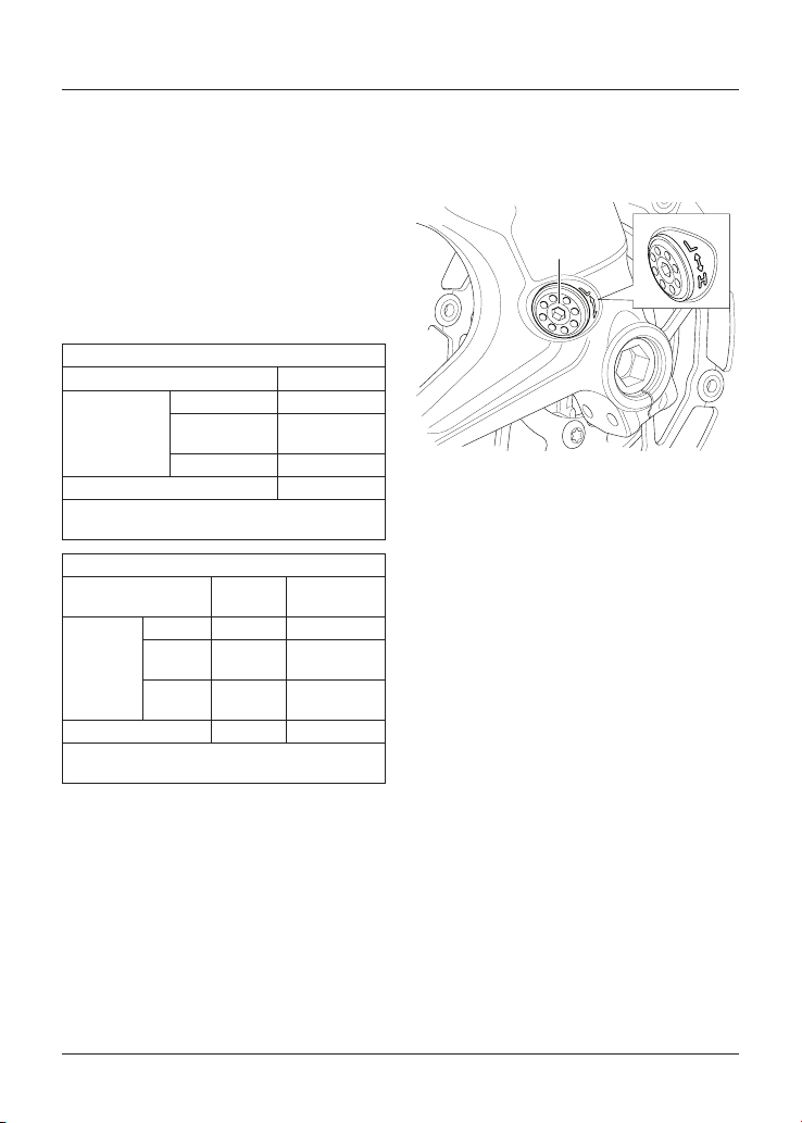
Maintenance and Adjustment
128
Front Suspension Settings -
Thruxton RS
The motorcycle is delivered from the
factory with all the suspension settings
set at the Standard setting, as shown in
the relevant suspension tables.
The details shown in the tables are only
a guide. Setting requirements may vary
for rider and passenger weight and
personal preferences.
Preload Suspension Settings
Loading Condition Spring Preload
1
Solo Riding
Standard 7. 0
Comfort
(Softer)
7. 0
Sport (Firmer) 7. 0
Rider and Passenger 7. 0
1
Number of adjuster turns clockwise from the
fully anticlockwise position.
Damping Suspension Settings
Loading Condition
Rebound
Damping
2
Compression
Damping
2
Solo Riding
Standard 5.0 5.25
Comfort
(Softer)
6.5 8.5
Sport
(Firmer)
2.0 2.0
Rider and Passenger 4.0 5.25
2
Number of adjuster turns anticlockwise from
the fully clockwise position.
Front Suspension Preload
Adjustment - Thruxton RS Only
The preload adjuster is located at the
bottom of the front suspension unit.
1
1. Front suspension preload adjuster
To adjust the preload setting:
• Rotate the adjuster clockwise
to increase, or anticlockwise to
decrease using the adjustment tool
located in the right hand side panel.
• Always count the number of turns
from the fully clockwise position.
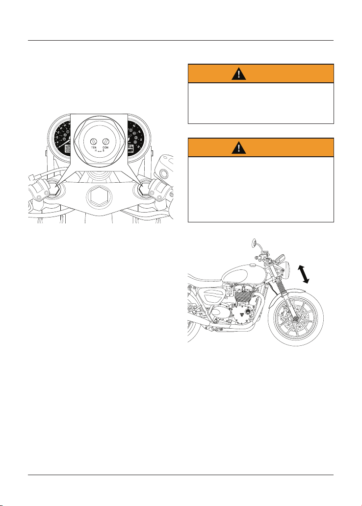
Maintenance and Adjustment
129
Front Suspension Rebound and
Compression Damping Adjustment -
Thruxton RS Only
The rebound and compression damping
adjusters are located at the top of each
fork.
Front Suspension Rebound and
Compression Damping Adjusters
To adjust the rebound damping setting:
• Rotate the TEN slotted adjuster
clockwise to increase, or anti-
clockwise to decrease.
• Always count the number of turns
from the fully clockwise position.
To adjust the compression damping
setting:
• Rotate the COM slotted adjuster
clockwise to increase, or anti-
clockwise to decrease.
• Always count the number of turns
from the fully clockwise position.
Front Fork Inspection
Warning
Riding the motorcycle with defective
or damaged suspension is dangerous
and may lead to loss of control and an
accident.
Warning
Never attempt to dismantle any part
of the suspension units
All suspension units contain
pressurised oil.
Skin and eye damage can result from
contact with the pressurised oil.
Street Twin Shown
Maintenance and Adjustment
130
To inspect the forks:
• Position the motorcycle on level
ground.
• While holding the handlebars and
applying the front brake, pump the
forks up and down several times.
• If roughness or excessive stiffness
is detected, consult your authorised
Triumph dealer.
• Examine each fork for any sign of
damage, scratching of the slider
surface, or for oil leaks.
• If any damage or leakage is found,
consult an authorised Triumph
dealer.
Rear Suspension
Caution
The rear suspension units on the
Thruxton RS are fitted with a
protective film label. This protective
film label will gradually wear. This wear
is normal and not considered to be a
fault. It does not affect the safety,
operation or performance of the rear
suspension.
If the motorcycle is used in dirty
or dusty environments, the wear
on the protective film labels will be
accelerated.
To reduce the wear on the protective
film labels, dirt should be washed from
between them after use in dirty or
dusty environments.
The protective film labels are
replaceable and can be replaced by an
authorised Triumph dealer.
The Thruxton RS suspension has three
different rear adjustment settings;
spring preload, rebound damping and
compression damping. All other models
only have adjustable spring preload
settings.
The Standard rear suspension preload
settings provide a comfortable ride
and good handling characteristics
for general, solo riding. The following
tables show suggested settings for
rear suspension under different load
conditions for all models.
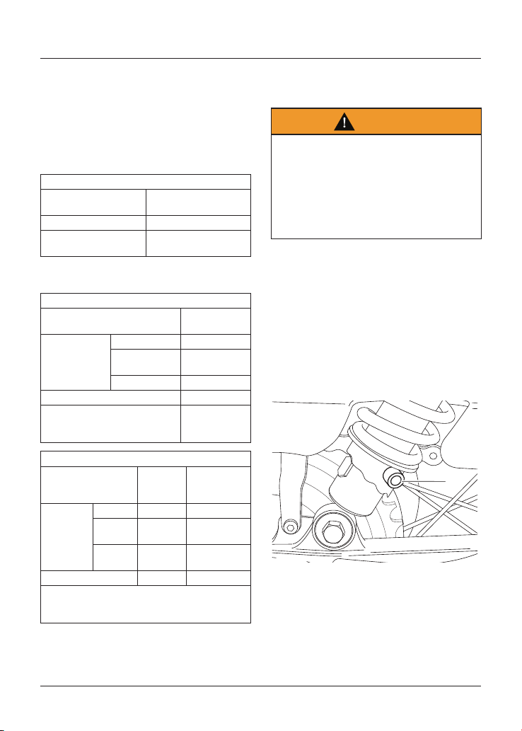
Maintenance and Adjustment
131
Rear Suspension Settings
The details shown in the tables are only
a guide. Setting requirements may vary
for rider and passenger weight and
personal preferences.
All Models except Thruxton RS
Preload Suspension Settings
Loading Condition
Rear Spring Preload
Adjuster Position
Solo Riding - Standard 1
Rider, Passenger and
Luggage
5
Thruxton RS Only
Preload Suspension Settings
Loading Condition
Rear Spring
Preload
1
Solo Riding
Standard 1
Comfort
(Softer)
1
Sport (Firmer) 1
Rider and Passenger 3
1
Position 1 is minimum (fully
clockwise) and position 3 is
maximum (fully anticlockwise).
Damping Suspension Settings
Loading Condition
Rear
Rebound
Damping
2
Rear
Compression
Damping
2
Solo Riding
Standard 24 16
Comfort
(Softer)
44 20
Sport
(Firmer)
12 8
Rider and Passenger 15 10
2
Number of clicks anticlockwise from the fully
clockwise position noting that the first stop
(click) is counted as one.
Rear Suspension Preload
Adjustment
Warning
Make sure that the adjusters are
set to the same setting on both rear
suspension units.
Settings that vary from left to right
may affect handling and stability
resulting in loss of motorcycle control
and an accident.
All Models except Thruxton RS
Rear adjuster settings are counted from
one with position one being with the
adjuster turned fully anticlockwise.
There are five adjuster positions in total.
Position five gives the maximum amount
of spring preload.
The spring preload adjuster is located at
the bottom of the rear suspension unit.
1
1. Rear suspension preload adjusters
To adjust the rear suspension spring
preload setting:
• Insert the adjustment tool (located
in the right hand side panel) into the
hole in the adjuster ring.
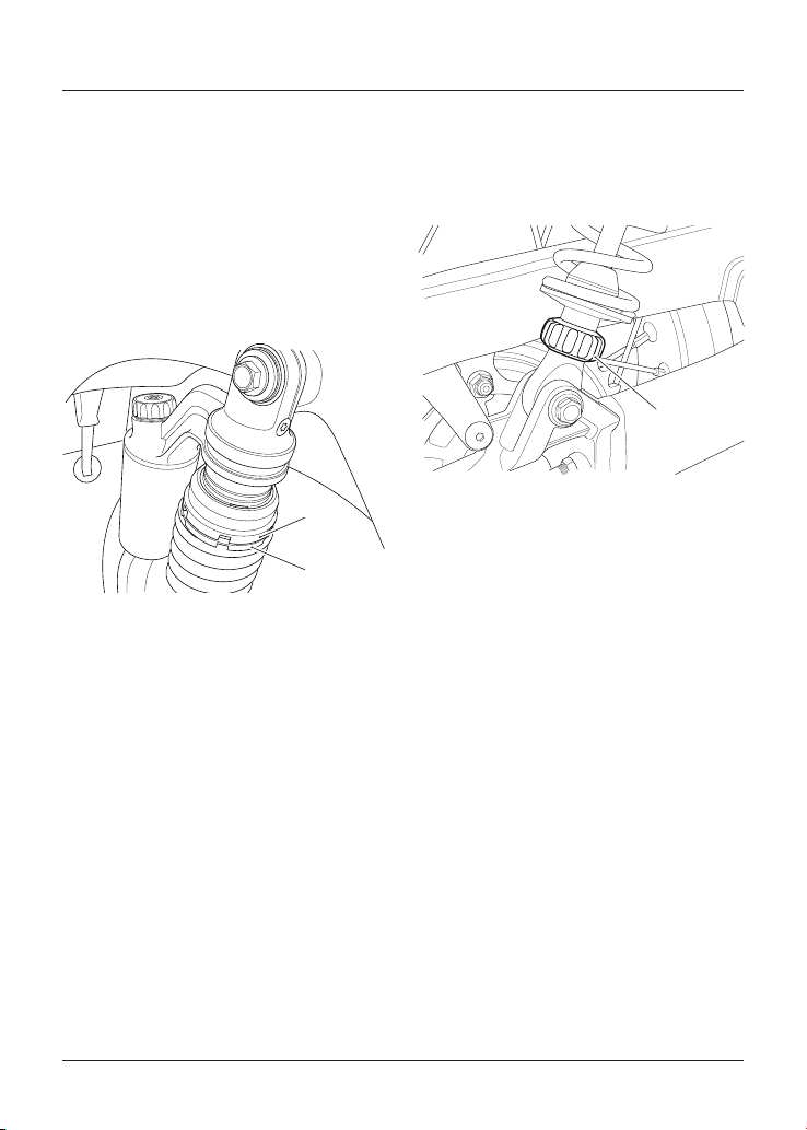
Maintenance and Adjustment
132
• Turn the adjuster ring clockwise
to increase spring preload, and
anticlockwise to decrease spring
preload. When delivered from the
factory, the preload adjuster will be
set at position one.
Rear Suspension Preload
Adjustment - Thruxton RS Only
The spring preload adjuster is located at
the top of the rear suspension unit.
1
2
1. Lower adjuster ring
2. Top adjuster ring
To adjust the rear suspension spring
preload setting:
• Use the two C-spanners located
under the seat.
• Hold the top adjuster ring in place
with one C-spanner, and adjust the
lower adjuster ring with the other
C-spanner.
• Turn the lower adjuster ring
clockwise (viewed from above)
to decrease spring preload and
anticlockwise to increase spring
preload. There are three defined
positions to select from.
Rear Suspension Rebound Damping
Adjustment - Thruxton RS Only
The rebound damping adjuster is
located at the bottom of the rear
suspension unit.
1
1. Rear suspension rebound damping
adjuster
To adjust the rebound damping setting:
• Look upwards from the bottom of
the suspension unit to the top of
the suspension unit, and rotate the
adjuster clockwise to increase and
anticlockwise to decrease.
• Always count the number of
adjuster clicks anticlockwise from
the fully clockwise position.
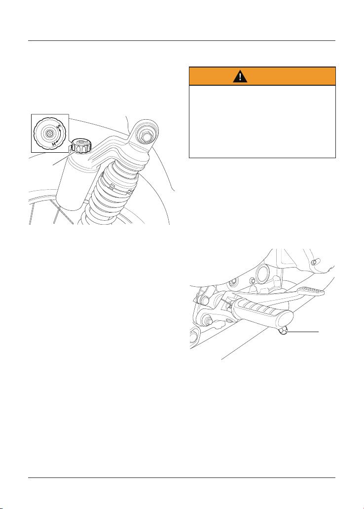
Maintenance and Adjustment
133
Rear Suspension Compression
Damping Adjustment - Thruxton RS
Only
The compression damping adjuster
is located at the top of the rear
suspension unit.
1
1. Rear suspension compression damping
adjuster
To adjust the compression damping
setting:
• Rotate the adjuster clockwise
to increase, or anticlockwise to
decrease.
• Always count the number of
adjuster clicks anticlockwise from
the fully clockwise position.
Bank Angle Indicators
Warning
Use of a motorcycle with bank angle
indicators worn beyond the maximum
limit will allow the motorcycle to be
banked to an unsafe angle.
Banking to an unsafe angle may cause
instability, loss of motorcycle control
and an accident.
Bank angle indicators are located on the
rider’s footrests.
Regularly check the bank angle
indicators for wear.
Bank angle indicators must be replaced
when they have reached the maximum
wear limit of 5 mm in length.
1
1. Bank angle indicator
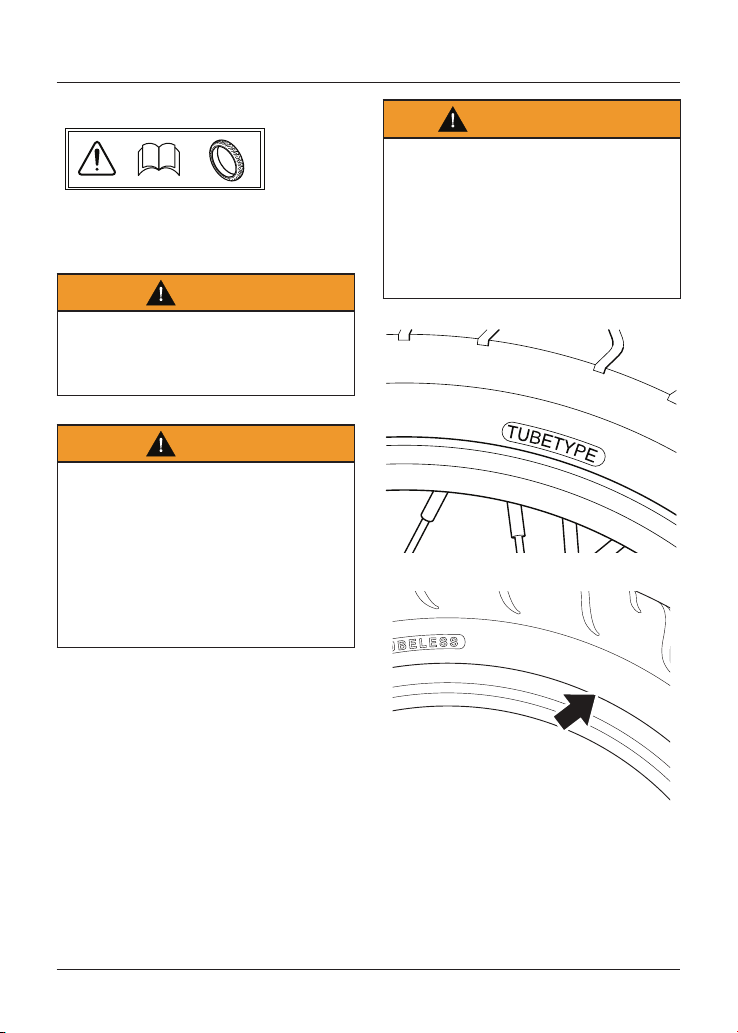
Maintenance and Adjustment
134
Tyres
This motorcycle is equipped with spoked
wheels which require a tyre suitable for
use with an inner tube.
Warning
Failure to use an inner tube in a
spoked wheel will cause deflation of
the tyre resulting in loss of motorcycle
control and an accident.
Warning
Inner tubes must only be used on
motorcycles fitted with spoked wheels
and with tyres marked 'TUBE TYPE'.
Some brands of approved tyres
marked 'TUBELESS' may be suitable for
use with an inner tube. Where this is
the case, the tyre wall will be marked
with text permitting the fitment of an
inner tube (see illustration below).
Warning Continued
Use of an inner tube with a tyre
marked 'TUBELESS', and NOT marked
as suitable for use with an inner
tube, or use of an inner tube on an
alloy wheel marked 'SUITABLE FOR
TUBELESS TYRES' will cause deflation
of the tyre resulting in loss of
motorcycle control and an accident.
Typical Tyre Marking
O
N
T
U
B
E
T
Y
P
E
R
I
M
F
I
T
A
T
U
B
E
Typical Tyre Marking - Tubeless Tyre
Suitable For Use With An Inner Tube
Maintenance and Adjustment
135
Tyre Inflation Pressures
Warning
Incorrect tyre inflation will cause
abnormal tread wear and instability
problems that may lead to loss of
control and an accident.
Under inflation may result in the tyre
slipping on, or coming off the rim.
Overinflation will cause instability and
accelerated tread wear.
Both conditions are dangerous as they
may cause loss of control leading to
an accident.
Correct inflation pressure will provide
maximum stability, rider comfort and
tyre life. Always check tyre pressures
before riding when the tyres are cold.
Check tyre pressures daily and adjust if
necessary. See the Specification section
for details of the correct inflation
pressures.
Tyre Pressure Monitoring System
(TPMS) (if fitted)
Caution
An adhesive label is fitted to the wheel
rim to indicate the position of the tyre
pressure sensor.
Care must be taken when replacing
the tyres to prevent any damage to
the tyre pressure sensors.
Always have your tyres fitted by your
authorised Triumph dealer and inform
them that tyre pressure sensors are
fitted to the wheels.
Caution
Do not use anti puncture fluid or any
other item likely to obstruct air flow
to the TPMS sensor’s orifices. Any
blockage to the air pressure orifice of
the TPMS sensor during operation will
cause the sensor to become blocked,
causing irreparable damage to the
TPMS sensor assembly.
Damage caused by the use of
anti puncture fluid or incorrect
maintenance is not considered a
manufacturing defect and will not be
covered under warranty.
Always have your tyres fitted by your
authorised Triumph dealer and inform
them that tyre pressure sensors are
fitted to the wheels.
The tyre pressures shown on your
instruments indicate the actual tyre
pressure at the time of selecting
the display. This may differ from the
inflation pressure set when the tyres
are cold because tyres become warmer
during riding, causing the air in the tyre
to expand and increase the inflation
pressure. The cold inflation pressures
specified by Triumph take account of
this.
Only adjust tyre pressures when
the tyres are cold using an accurate
pressure gauge. Do not use the tyre
pressure display on the instruments.
Maintenance and Adjustment
136
Tyre Wear
As the tyre tread wears down, the tyre
becomes more susceptible to punctures
and failure. It is estimated that 90%
of all tyre problems occur during the
last 10% of tread life (90% worn). It is
recommended that tyres are changed
before they are worn to their minimum
tread depth.
Minimum Recommended Tread
Depth
Warning
Operation with excessively worn tyres
is hazardous and will adversely affect
traction, stability and handling which
may lead to loss of control and an
accident.
When tubeless tyres, used without a
tube, become punctured, leakage is
often very slow. Always inspect tyres
very closely for punctures. Check
the tyres for cuts, embedded nails or
other sharp objects. Operation with
punctured or damaged tyres will
adversely affect motorcycle stability
and handling which may lead to loss of
control or an accident.
Check the rims for dents or
deformation. Operation with damaged
or defective wheels or tyres is
dangerous and loss of motorcycle
control or an accident could result.
Always consult your authorised
Triumph dealer for tyre replacement,
or for a safety inspection of the tyres.
In accordance with the periodic
maintenance chart, measure the depth
of the tread with a depth gauge, and
replace any tyre that has worn to, or
beyond the minimum allowable tread
depth specified in the table below:
Under 80 mph
(130 km/h)
2 mm (0.08 in)
Over 80 mph
(130 km/h)
Front 2 mm (0.08 in)
Rear 3 mm (0.12 in)
Tyre Replacement
All Triumph motorcycles are carefully
and extensively tested in a range
of riding conditions to ensure that
the most effective tyre combinations
are approved for use on each model.
It is essential that approved tyres
and inner tubes (if installed) fitted in
approved combinations, are used when
purchasing replacement items. The use
of non-approved tyres and inner tubes,
or approved tyres and inner tubes in
non-approved combinations, may lead
to motorcycle instability, loss of control
and an accident.
A list of approved tyres and inner tubes
specific to your motorcycle are available
from your authorised Triumph dealer, or
on the Internet at www. triumph. co. uk.
Always have tyres and inner tubes
fitted and balanced by your authorised
Triumph dealer who has the necessary
training and skills to ensure safe,
effective fitment.
Maintenance and Adjustment
137
When replacement tyres or inner tubes
are required, consult your authorised
Triumph dealer who will arrange for the
tyres and inner tubes to be selected,
in a correct combination, from the
approved list and fitted according to
the tyre and inner tube manufacturer's
instructions.
Initially, the new tyres and inner tubes
will not produce the same handling
characteristics as the worn tyres and
inner tubes and the rider must allow
adequate riding distance (approximately
100 miles (160 km)) to become
accustomed to the new handling
characteristics.
24 hours after fitting, the tyre
pressures must be checked and
adjusted, and the tyres and inner
tubes examined for correct seating.
Rectification must be carried out as
necessary. The same checks and
adjustments must also be carried out
when 100 miles (160 km) have been
travelled after fitting.
Warning
Inner tubes must only be used on
motorcycles fitted with spoked wheels
and with tyres marked 'TUBE TYPE'.
Some brands of approved tyres
marked 'TUBELESS' may be suitable for
use with an inner tube. Where this is
the case, the tyre wall will be marked
with text permitting the fitment of an
inner tube.
Warning Continued
Use of an inner tube with a tyre
marked 'TUBELESS', and NOT marked
as suitable for use with an inner
tube, or use of an inner tube on an
alloy wheel marked 'SUITABLE FOR
TUBELESS TYRES' will cause deflation
of the tyre resulting in loss of
motorcycle control and an accident.
Warning
Do not install tube type tyres on
tubeless rims.
The bead will not seat and the tyres
could slip on the rims, causing rapid
tyre deflation that may result in a loss
of motorcycle control and an accident.
Never install an inner tube inside a
tubeless tyre without the appropriate
marking. This will cause friction inside
the tyre and the resulting heat build-
up may cause the tube to burst
resulting in rapid tyre deflation, loss of
motorcycle control and an accident.
Warning
If a tyre or inner tube sustains a
puncture, the tyre and inner tube
must be replaced.
Failure to replace a punctured tyre
and inner tube, or operation with a
repaired tyre or inner tube can lead to
instability, loss of motorcycle control
or an accident.
Maintenance and Adjustment
138
Warning
If tyre damage is suspected, such
as after striking the kerb, ask your
authorised Triumph dealer to inspect
the tyre both internally and externally.
Tyre damage may not always be visible
from the outside.
Operation of the motorcycle with
damaged tyres could lead to loss of
control and an accident.
Warning
Use of a motorcycle with incorrectly
seated tyres or inner tubes,
incorrectly adjusted tyre pressures, or
when not accustomed to its handling
characteristics may lead to loss of
motorcycle control and an accident.
Warning
The ABS system operates by
comparing the relative speed of the
front and rear wheels.
Use of non-recommended tyres can
affect wheel speed and cause the ABS
function not to operate, potentially
leading to loss of motorcycle control
and an accident in conditions where
the ABS would normally function.
Warning
Accurate wheel balance is necessary
for safe, stable handling of the
motorcycle. Do not remove or change
any wheel balance weights. Incorrect
wheel balance may cause instability
leading to loss of control and an
accident.
When wheel balancing is required,
such as after tyre or inner tube
replacement, see your authorised
Triumph dealer.
Only use self-adhesive weights. Clip
on weights may damage the wheel,
tyre or inner tube resulting in tyre
deflation, loss of motorcycle control
and an accident.
Warning
Tyres and inner tubes that have been
used on a rolling road dynamometer
may become damaged. In some cases,
the damage may not be visible on the
external surface of the tyre.
Tyres and inner tubes must be
replaced after such use as continued
use of a damaged tyre or inner
tube may lead to instability, loss of
motorcycle control and an accident.
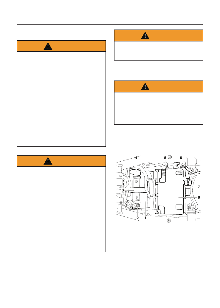
Maintenance and Adjustment
139
Battery
Warning
The battery contains sulphuric acid
(battery acid). Contact with skin or
eyes may cause severe burns. Wear
protective clothing and a face shield.
If battery acid gets on your skin, flush
with water immediately.
If battery acid gets in your eyes, flush
with water for at least 15 minutes
and SEEK MEDICAL ATTENTION
IMMEDIATELY.
If battery acid is swallowed, drink large
quantities of water and SEEK MEDICAL
ATTENTION IMMEDIATELY.
KEEP BATTERY ACID OUT OF THE
REACH OF CHILDREN.
Warning
Under certain circumstance the
battery may release explosive gases.
Make sure to keep all sparks, flames
and cigarettes away from the battery.
Do not attach jump leads to the
battery, touch the battery cables
together or reverse the polarity of
the cables, as any of these actions
may cause a spark which would
ignite battery gases causing a risk of
personal injury.
Make sure that there is adequate
ventilation when charging or using the
battery in an enclosed space.
Warning
The battery contains harmful
materials. Always keep children away
from the battery at all times.
Battery Removal
Warning
Make sure that the battery terminals
do not touch the motorcycle frame.
This may cause a short circuit or spark
which would ignite battery gases
causing a risk of personal injury.
Bonneville T100 (all models),
Bonneville T120 (all models),
Street Scrambler and Street Twin
12
3
56
7
8
4
1. Battery
2. Negative (-) terminal
3. Battery strap
4. Positive (+) terminal
5. Fixing
6. Rear light cable
7. Accessory cable
8. Engine Control Module (ECM) unit
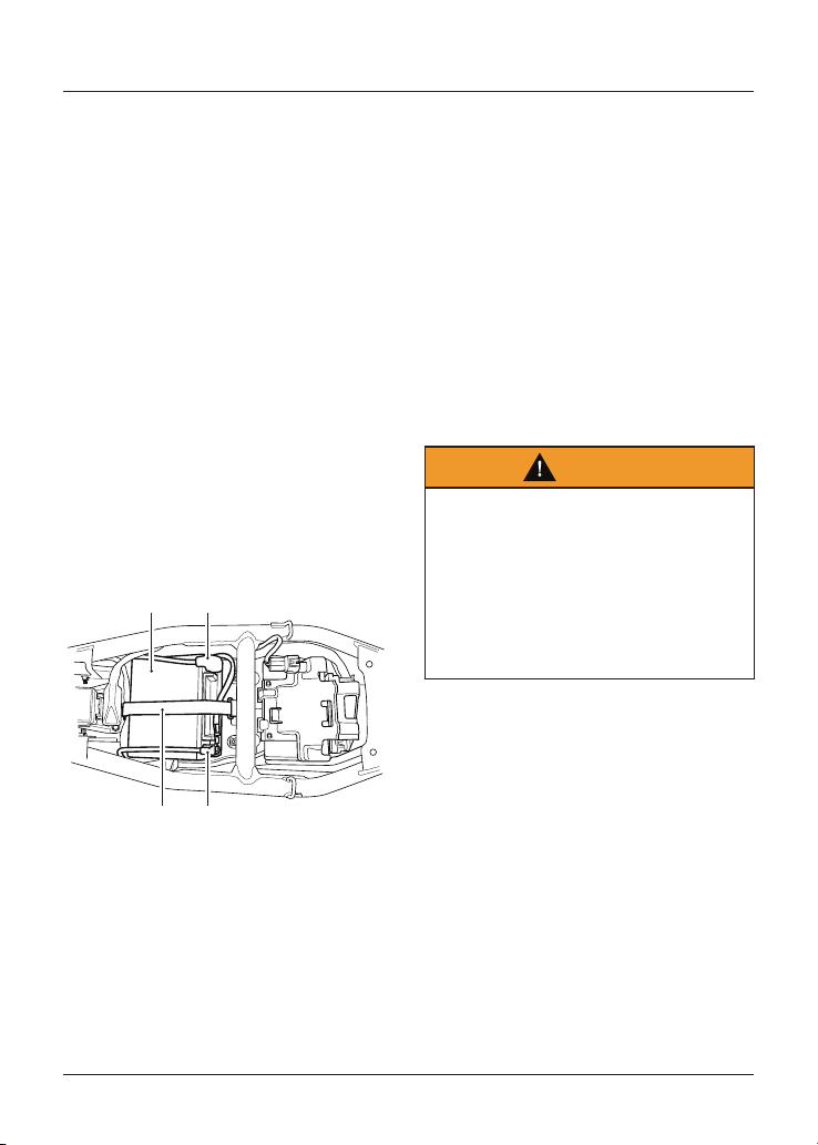
Maintenance and Adjustment
140
To remove the battery:
• Remove the seat (see page 72).
• Disconnect the battery leads,
negative (black) lead first.
• Release the rear light and accessory
cables.
• Release the fixing on the Engine
Control Module (ECM) unit.
• Lift the ECM unit and place to the
side allowing access to the battery.
Note
Make sure that the ECM unit is handled
with care during the battery removal or
installation process.
• Remove the battery strap.
• Detach the USB port socket.
• Take the battery out of the case.
Speed Twin and Thruxton RS
3
12
4
1. Battery
2. Positive (+) terminal
3. Negative (-) terminal
4. Battery strap
To remove the battery:
• Remove the seat (see page 72).
• Disconnect the battery leads,
negative (black) lead first.
• Remove the battery strap and the
USB port socket.
• Take the battery out of the case.
Battery Disposal
Should the battery ever require
replacement, the original battery must
be handed to a recycling agent who
will make sure that the dangerous
substances from which the battery
is manufactured do not pollute the
environment.
Battery Maintenance
Warning
Battery acid is corrosive and
poisonous and will cause damage to
unprotected skin.
Never swallow battery acid or allow it
to come into contact with the skin.
To prevent injury, always wear eye
and skin protection when handling the
battery.
The battery is a sealed type and does
not require any maintenance other
than checking the voltage and routine
recharging when required, such as
during storage.
Clean the battery using a clean,
dry cloth. Make sure that the cable
connections are clean.
It is not possible to adjust the battery
acid level in the battery; the sealing
strip must not be removed.
Maintenance and Adjustment
141
Battery Discharge
Caution
The charge level in the battery must
be maintained to maximise battery life.
Failure to maintain the battery charge
level could cause serious internal
damage to the battery.
Under normal conditions, the motorcycle
charging system will keep the
battery fully charged. However, if the
motorcycle is unused, the battery will
gradually discharge due to a normal
process called self discharge; the clock,
Engine Control Module (ECM) memory,
high ambient temperatures, or the
addition of electrical security systems
or other electrical accessories will all
increase this rate of battery discharge.
Disconnecting the battery from the
motorcycle during storage will reduce
the rate of discharge.
Battery Discharge During Storage
and Infrequent Use of the
Motorcycle
During storage or infrequent use of the
motorcycle, inspect the battery voltage
weekly using a digital multimeter.
Follow the manufacturer’s instructions
supplied with the meter.
Should the battery voltage fall below
12.7 Volts, the battery should be
charged.
Allowing a battery to discharge or
leaving it discharged for even a short
period of time causes sulphation of
the lead plates. Sulphation is a normal
part of the chemical reaction inside
the battery, however over time the
sulphate can crystallise on the plates
making recovery difficult or impossible.
This permanent damage is not covered
by the motorcycle warranty, as it is not
due to a manufacturing defect.
Keeping the battery fully charged
reduces the likelihood of it freezing
in cold conditions. Allowing a battery
to freeze will cause serious internal
damage to the battery.
Battery Charging
Warning
The battery gives off explosive gases;
keep sparks, flames and cigarettes
away. Provide adequate ventilation
when charging or using the battery in
an enclosed space.
The battery contains sulphuric acid
(battery acid). Contact with skin or
eyes may cause severe burns. Wear
protective clothing and a face shield.
If battery acid gets on your skin, flush
with water immediately.
If battery acid gets in your eyes, flush
with water for at least 15 minutes
and SEEK MEDICAL ATTENTION
IMMEDIATELY.
If battery acid is swallowed, drink large
quantities of water and SEEK MEDICAL
ATTENTION IMMEDIATELY.
KEEP BATTERY ACID OUT OF THE
REACH OF CHILDREN.
Maintenance and Adjustment
142
Caution
Do not use an automotive quick
charger as it may overcharge and
damage the battery.
For help with selecting a battery
charger, checking the battery voltage
or battery charging, contact your local
authorised Triumph dealer.
Should the battery voltage fall below
12.7 Volts, the battery should be charged
using a Triumph approved battery
charger. Always remove the battery
from the motorcycle and follow the
instructions supplied with the battery
charger.
For extended periods of storage
(beyond two weeks) the battery should
be removed from the motorcycle and
kept charged using a Triumph approved
maintenance charger.
Similarly, should the battery charge
fall to a level where it will not start the
motorcycle, remove the battery from
the motorcycle before charging.
Battery Installation
Warning
Make sure that the battery terminals
do not touch the motorcycle frame.
This may cause a short circuit or spark
which would ignite battery gases
causing a risk of personal injury.
Bonneville T100 (all models),
Bonneville T120 (all models),
Street Scrambler and Street Twin
To install the battery:
• Place the battery in the battery
case.
• Refit the USB port socket and
secure with the battery strap.
• Reconnect the battery, positive lead
(identified with red tape) first.
• Tighten the battery terminals to
4.5 Nm.
• Apply a light coat of grease to the
terminals to prevent corrosion.
• Cover the positive terminal with the
protective cap.
• Place the ECM unit in its original
position.
• Reconnect the rear light and
accessory cables.
• Refit the fixing to secure the ECM
unit.
• Refit the seat (see page 72).
Maintenance and Adjustment
143
Speed Twin and Thruxton RS
To install the battery:
• Place the battery in the battery
case.
• Secure with the battery strap and
make sure the USB port socket is
refitted.
• Reconnect the battery, positive lead
(identified with red tape) first.
• Tighten the battery terminals to
4.5 Nm.
• Apply a light coat of grease to the
terminals to prevent corrosion.
• Cover the positive terminal with the
protective cap.
• Refit the seat (see page 72).
Fuses
Warning
Always replace blown fuses with new
ones of the correct rating (as specified
on the fuse box cover) and never use a
fuse of higher rating.
Use of an incorrect fuse could lead
to an electrical problem, resulting in
motorcycle damage, loss of motorcycle
control and an accident.
Note
A blown fuse is indicated when all of the
systems protected by that fuse become
inoperative. When checking for a blown
fuse, use the table to establish which
fuse has blown.
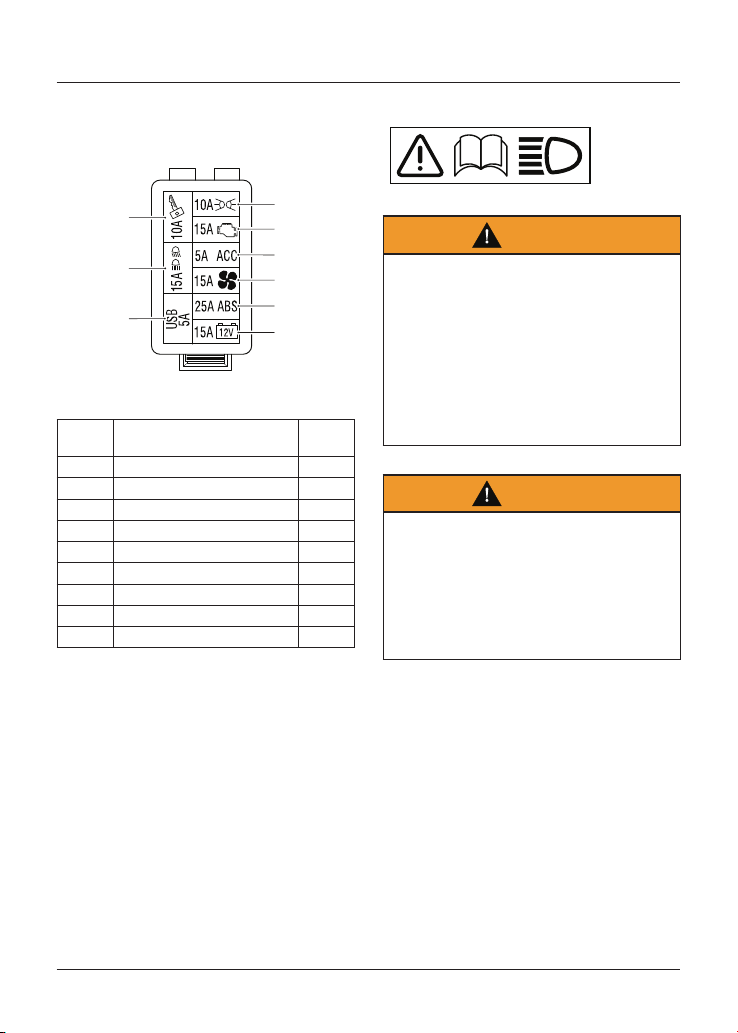
Maintenance and Adjustment
144
The fuse box is located underneath the
seat. To allow access to the fuse box,
the seat must be removed (see page 72).
9
8
7
1
2
3
4
5
6
Fuse Box
Position Circuit Protected
Rating
(Amps)
1 Auxiliary lights 10
2 Engine management system 15
3 Accessory socket 5
4 Cooling fan 15
5 ABS 25
6 Instruments and alarm 15
7 Ignition switch, starter circuit 10
8 Dip and high headlight beams 15
9 USB port socket 5
Headlights
Warning
Adjust road speed to suit the visibility
and weather conditions in which the
motorcycle is being operated.
Make sure that the head light beam is
adjusted to illuminate the road surface
sufficiently far ahead without dazzling
oncoming traffic.
An incorrectly adjusted headlight may
impair visibility causing an accident.
Warning
Never attempt to adjust a headlight
beam when the motorcycle is in
motion.
Any attempt to adjust a headlight
beam when the motorcycle is in
motion may result in loss of control
and an accident.
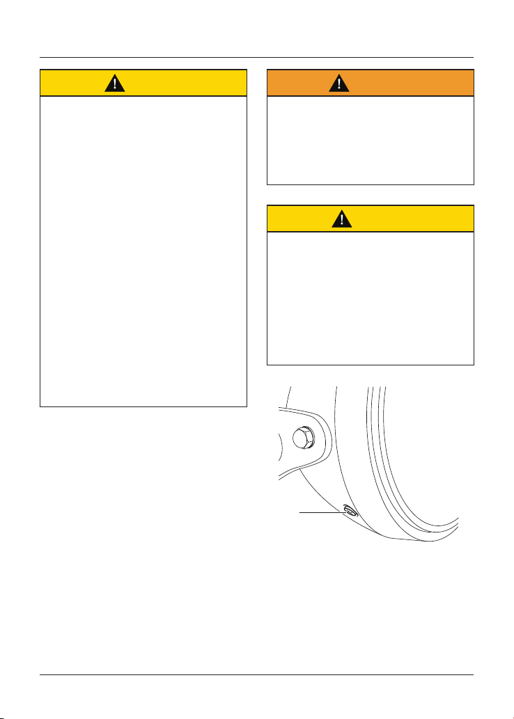
Maintenance and Adjustment
145
Caution
Do not cover the headlight or lens with
any item likely to obstruct air flow to,
or prevent heat escaping from, the
headlight lens.
Covering the headlight lens during
operation with items of clothing,
luggage, adhesive tape, devices
intended to alter or adjust the
headlight beam or non genuine
headlight lens covers will cause the
headlight lens to overheat and distort,
causing irreparable damage to the
headlight assembly.
Damage caused by overheating is
not considered a manufacturing
defect and will not be covered under
warranty.
If the headlight must be covered
during use - such as taping of
the headlight lens required during
closed-course conditions - the
headlight must be disconnected.
Headlight/Position Light Bulb
Replacement
The headlight unit consists of a
headlight bulb and position bulb that
can be replaced following the headlight
bulb replacement procedure.
Daytime Running Lights (if fitted)
The Daytime Running Lights (DRL) are
situated within the headlight assembly
and are sealed, maintenance free LED
units. If DRL are fitted then there is no
position bulb.
Warning
The bulbs become hot during use.
Always allow sufficient time for the
bulbs to cool before handling.
Avoid touching the glass part of the
bulb. If the glass is touched or gets
dirty, clean with alcohol before reuse.
Caution
The use of non-approved headlight
bulbs may result in damage to the
headlight lens.
Use a genuine Triumph supplied
headlight bulb as specified in the
Triumph Parts Catalogue.
Always have replacement headlight
bulbs installed by an authorised
Triumph dealer.
1
1. Headlight rim screws (one of two)
To remove the headlight rim:
• Disconnect the battery, negative
(black) lead first.
• Remove the headlight rim screws.
• Detach the headlight and rim
assembly from the headlight bowl.
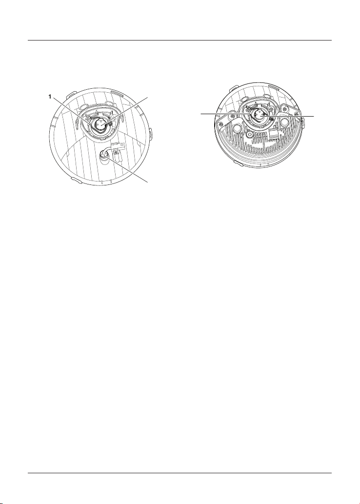
Maintenance and Adjustment
146
Bonneville T100,
Bonneville T100 Bud Ekins,
Street Scrambler and Street Twin
1
2
3
1. Wire retainer
2. Headlight bulb
3. Position bulb
To remove the headlight and position
light bulb:
• While supporting the light unit,
disconnect the multipin electrical
connector from the headlight bulb
and the connector from the position
light.
• Remove the rubber dust cover.
• Unhook the headlight bulb's wire
retainer.
• The headlight bulb can now be
removed.
• To remove the position light bulb,
detach the bulb holder from the
headlight body and release the bulb.
• Installation is the reversal of
removal.
Bonneville T120 (all models),
Speed Twin and Thruxton RS
1
2
1. Wire retainer
2. Headlight bulb
To remove the headlight and position
light bulb:
• While supporting the light unit,
disconnect the multipin electrical
connector from the headlight bulb.
• Remove the rubber dust cover.
• Unhook the headlight bulb's wire
retainer.
• The headlight bulb can now be
removed.
• Installation is the reversal of
removal.
• The position bulb is situated within
the headlight assembly and is a
sealed, maintenance-free LED unit.
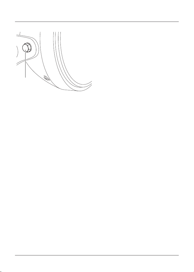
Maintenance and Adjustment
147
Headlight Adjustment
1
1. Headlight assembly mounting bolt
To adjust the headlight beam:
• Always make sure the handlebars
are in the straight ahead position.
• Vertical adjustment of the headlight
beam is controlled by loosening the
headlight assembly mounting bolts
and altering the position of the
headlight assembly.
• Retighten the headlight assembly
mounting bolts after adjustment to
10 Nm.
Rear Lights
The LED rear light units are sealed,
maintenance free LED units. The rear
light units must be replaced in the event
of the failure of the rear lights.
Multifunctional Rear Lights
(if fitted)
Bonneville T120 Ace and Speed Twin
The multifunctional rear light units
operate as the rear position light, brake
light and direction indicators.
The multifunctional rear light units are
a sealed, maintenance free LED unit and
must be replaced in the event of the
failure of the rear lights.
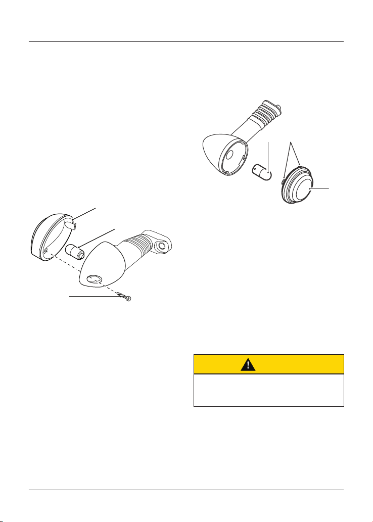
Maintenance and Adjustment
148
Direction Indicator Lights
The motorcycle is fitted with either LED
or bulb direction indicator lights.
LED Direction Indicator Lights
The LED direction indicator light units
are sealed, maintenance free LED units.
The direction indicator light assembly
must be replaced in the event of the
failure of the direction indicator.
Street Scrambler and Street Twin
Direction Indicator Bulb
Replacement
1
3
2
1. Lens
2. Bulb
3. Indicator lens screw
The lens on each indicator light is held
in place by an indicator lens screw
located in the body of the light unit.
To replace the direction indicator light
bulb:
• Release the indicator lens screw and
remove the lens to gain access to
the bulb for replacement.
• Carefully remove the bulb and
replace it with a new bulb.
• Installation is the reverse of the
removal procedure.
Bonneville T100, Bonneville T120,
Bonneville T120 Ace and
Thruxton RS Direction Indicator
Bulb Replacement
3
21
1. Bulb
2. Locating tangs
3. Lens
To replace the direction indicator light
bulb:
• Carefully twist the lens anti-
clockwise and remove from the
indicator to gain access to the bulb.
• Gently press the bulb inwards and
twist anticlockwise. Replace with a
new bulb.
• Installation for the bulb is the
reverse of the removal procedure.
Caution
When installing the lens, make sure
that the locating tangs are correctly
aligned to the indicator body.
• To install the indicator lens, align
the locating tangs with the indicator
body and twist anticlockwise to
secure.
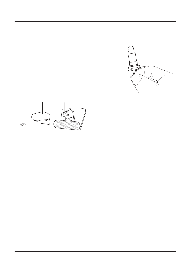
Maintenance and Adjustment
149
License Plate Light
Bonneville T100 (all models),
Bonneville T120 (all models),
Speed Twin and Thruxton RS
The license plate light unit is a sealed,
maintenance free LED unit. The license
plate light unit must be replaced in the
event of the failure of the license plate
light.
Street Scrambler and Street Twin
321 4
1. Fixing
2. Lens unit
3. Bulb
4. License plate bracket
To change the license plate light bulb:
• Disconnect the battery, negative
black lead first.
• Release the fixing from the lens
unit.
• Remove the lens unit from the
license plate bracket.
• Detach the bulb retainer from the
lens unit.
1
2
1. Bulb
2. Bulb retainer
• Carefully remove the bulb from the
bulb retainer. Fit a new bulb into the
bulb retainer.
• Refit the bulb retainer into the lens
unit.
• Refit the lens unit to the license
plate bracket.
• Tighten the fixing to 1 Nm.
• Reconnect the battery, positive (red)
lead first and tighten the battery
terminals to 4.5 Nm.
• Apply a light coat of grease to the
terminals to prevent corrosion.
• Cover the positive terminal with the
protective cap.

Maintenance and Adjustment
150
This page intentionally left blank

Cleaning and Storage
151
Cleaning and Storage
Table of Contents
Cleaning 152
Preparation for Washing 152
Where to be Careful 153
Washing 153
After Washing 154
Care of Gloss Paintwork 154
Care of Matt Paintwork 154
Aluminium Items - not Lacquered or Painted 154
Cleaning of Chrome and Stainless Steel Items 155
Black Chrome 155
Cleaning of the Exhaust System 156
Seat Care 157
Windscreen Cleaning (if fitted) 157
Care of Leather Products 158
Storage 159

Cleaning and Storage
152
Cleaning
Frequent, regular cleaning is an
essential part of the maintenance of
your motorcycle. If regularly cleaned,
the appearance will be preserved for
many years.
Cleaning with cold water containing an
automotive cleaner is essential at all
times but particularly so after exposure
to sea breezes, sea water, dusty or
muddy roads and in winter when roads
are treated for ice and snow.
Do not use household detergent, as
the use of such products will lead to
premature corrosion.
Although, under the terms of your
motorcycle warranty, cover is provided
against the corrosion of certain items,
the owner is expected to observe this
reasonable advice which will safeguard
against corrosion and enhance the
appearance of the motorcycle.
Preparation for Washing
Before washing, precautions must be
taken to keep water off the following
places.
Rear opening of the exhausts: Cover
with a plastic bag secured with rubber
bands.
Clutch and brake levers, switch housings
on the handlebar: Cover with plastic
bags.
Ignition switch and steering lock: Cover
the keyhole with tape.
Remove any items of jewellery such
as rings, watches, zips or belt buckles,
which may scratch or otherwise damage
painted or polished surfaces.
Use separate cleaning sponges or
cleaning cloths for washing painted/
polished surfaces and chassis areas.
Chassis areas (such as wheels and
under mudguards) will be exposed to
more abrasive road grime and dust,
which may then scratch painted or
polished surfaces, if the same sponge or
cleaning cloths are used.
Cleaning and Storage
153
Where to be Careful
Caution
Do not spray any water at all near the
air intake duct.
The air intake duct is normally located
under the rider’s seat, under the fuel
tank or near the steering head.
Any water sprayed in this area could
enter the airbox and engine, causing
damage to both items.
Caution
Use of high pressure spray washers is
not recommended.
When using pressure washers, water
may be forced into bearings and other
components causing premature wear
from corrosion and loss of lubrication.
Avoid spraying water with any great
force near the following places:
• Instruments,
• Brake cylinders and brake calipers,
• Under the fuel tank,
• Air intake duct,
• Headstock bearings,
• Wheel bearings,
• Suspension seals and bearings.
Note
Use of soaps that are highly alkaline will
leave a residue on painted surfaces, and
may also cause water spotting.
Always use a low alkaline soap to aid
the cleaning process.
Washing
To wash the motorcycle, do the
following:
• Prepare a mixture of cold water and
mild automotive cleaner. Do not use
a highly alkaline soap as commonly
found at commercial car washes
because it leaves a residue.
• Wash the motorcycle with a sponge
or soft cloth. Do not use abrasive
scouring pads or steel wool. They
will damage the finish.
• Rinse the motorcycle thoroughly
with cold water.
Cleaning and Storage
154
After Washing
Warning
Never wax or lubricate the brake discs.
Always clean the brake disc with a
proprietary brand of oil-free brake disc
cleaner.
Waxed or lubricated brake discs may
cause loss of braking power and an
accident.
After washing the motorcycle, do the
following:
1. Remove the plastic bags and tape,
and clear the air intakes.
2. Lubricate the pivots, bolts and nuts.
3. Test the brakes before motorcycle
operation.
4. Use a dry cloth or chamois leather
to absorb water residue. Do
not allow water to stand on the
motorcycle as this will lead to
corrosion.
5. Start the engine and run it for
5 minutes. Make sure that there is
adequate ventilation for the exhaust
fumes.
Care of Gloss Paintwork
Gloss paintwork should be washed
and dried as described above, then
protected using a high quality
automotive polish. Always follow the
manufacturer’s instructions and repeat
regularly to maintain your motorcycle’s
appearance.
Care of Matt Paintwork
Matt paintwork requires no greater care
than that already recommended for
high gloss paintwork.
• Do not use any polish or wax on
matt paintwork.
• Do not try and polish out scratches.
Aluminium Items - not
Lacquered or Painted
Items such as brake and clutch levers,
wheels, engine covers, engine cooling
fins, upper and lower yokes and
throttle bodies on some models must
be correctly cleaned to preserve their
appearance. Please contact your dealer
if you are unsure which components on
your motorcycle are aluminium parts
not protected by paint or lacquer, and
for guidance on how to clean those
items.
Use a proprietary brand of aluminium
cleaner which does not contain abrasive
or caustic elements.
Clean aluminium items regularly,
in particular after use in inclement
weather, where the components must
be hand washed and dried each time
the machine is used.
Warranty claims due to inadequate
maintenance will not be allowed.
Cleaning and Storage
155
Cleaning of Chrome and
Stainless Steel Items
All chrome and stainless steel parts
of your motorcycle must be cleaned
regularly to avoid a deterioration of its
appearance.
Washing
Wash as previously described.
Drying
Dry the chrome and stainless steel
parts as far as possible with a soft cloth
or chamois leather.
Protecting
Caution
The use of products containing
silicone will cause discolouration of the
chrome and stainless steel parts and
must not be used.
The use of abrasive cleaning products
will damage the finish and must not be
used.
When the chrome and stainless steel is
dry, apply a suitable proprietary chrome
cleaner on to the surface, following the
manufacturer’s instructions.
It is recommended that regular
protection be applied to the motorcycle
as this will both protect and enhance its
appearance.
Black Chrome
Items such as headlight bowls and
mirrors on some models must be
correctly cleaned to preserve their
appearance. Please contact your dealer
if you are unsure which components
on your motorcycle are black chrome
parts. Maintain the appearance of
black chrome items by rubbing a small
amount of light oil into the surface.
Cleaning and Storage
156
Cleaning of the Exhaust
System
All parts of the exhaust system of your
motorcycle must be cleaned regularly to
avoid a deterioration of its appearance.
These instructions can be applied to
chrome, brushed stainless steel and
carbon fibre components; matt painted
exhaust systems should be cleaned as
above, noting the care instructions in
the Matt Paintwork section previously.
Note
The exhaust system must be cool before
washing to prevent water spotting.
Washing
Wash as previously described.
Make sure that no soap or water enters
the exhausts.
Drying
Dry the exhaust system as far as
possible with a soft cloth or chamois
leather. Do not run the engine to dry
the system or spotting will occur.
Protecting
Caution
The use of products containing
silicone will cause discolouration of the
chrome and stainless steel parts and
must not be used.
The use of abrasive cleaning products
will damage the finish and must not be
used.
When the exhaust system is dry, apply
a suitable proprietary motorcycle
protection spray onto the surface,
following the manufacturer’s
instructions.
It is recommended that regular
protection be applied to the system as
this will both protect and enhance the
system's appearance.
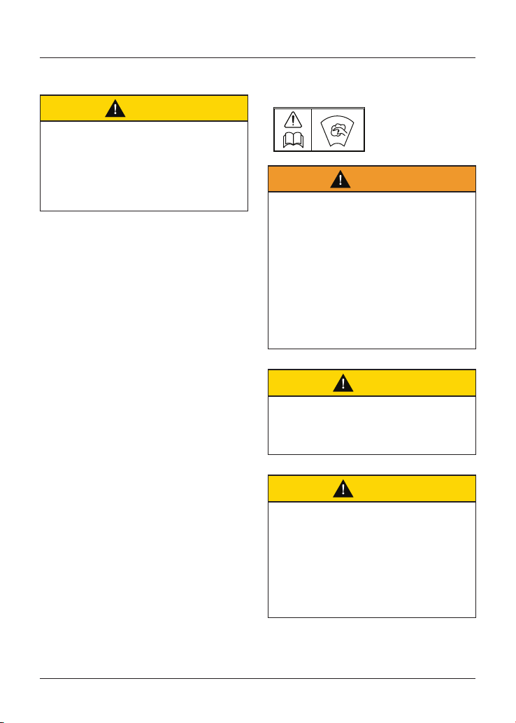
Cleaning and Storage
157
Seat Care
Caution
Use of chemicals or high pressure
spray washers is not recommended for
cleaning the seat.
Using chemicals or high pressure
spray washers may damage the seat
cover.
To help maintain its appearance, clean
the seat using a sponge or cleaning
cloth with soap and water.
Windscreen Cleaning
(if fitted)
Warning
Never attempt to clean the windscreen
while the motorcycle is in motion as
releasing the handlebars may cause
loss of motorcycle control and an
accident.
Operation of the motorcycle with a
damaged or scratched windscreen
will reduce the rider's forward vision.
Any such reduction in forward vision
is dangerous and may lead to loss of
motorcycle control and an accident.
Caution
Corrosive chemicals such as battery
acid will damage the windscreen.
Never allow corrosive chemicals to
contact the windscreen.
Caution
Products such as window cleaning
fluids, insect remover, rain repellent,
scouring compounds, petrol or strong
solvents such as alcohol, acetone,
carbon tetrachloride, etc. will damage
the windscreen.
Never allow these products to contact
the windscreen.

Cleaning and Storage
158
Clean the windscreen with a solution of
mild soap or detergent and cold water.
After cleaning, rinse well and then dry
with a soft, lint-free cloth.
If the transparency of the windscreen is
reduced by scratches or oxidation which
cannot be removed, the windscreen
must be replaced.
Care of Leather Products
It is recommend that the leather
products are periodically cleaned with a
damp cloth and allowed to dry naturally
at room temperature. This will maintain
the appearance of the leather and
ensure the long life of the product.
The Triumph leather product is a natural
product and lack of care can result in
damage and permanent wear.
Follow these simple instructions to
prolong the life of the leather product:
• Do not use household cleaning
products, bleach, detergents
containing bleach or any kind of
solvent to clean the leather product.
• Do not immerse the leather product
in water.
• Avoid direct heat from fires and
radiators which can dry out and
distort the leather.
• Do not leave the leather product in
direct sunlight for prolonged periods
of time.
• Do not dry the leather product by
applying direct heat to it at any
time.
• If the leather product does get wet,
absorb any excess water with a soft
clean cloth then leave the leather
product to dry naturally at room
temperature.
• Avoid exposure of the leather
product to high levels of salt, for
example sea/salt water or road
surfaces that have been treated
during the winter for ice and snow.
Cleaning and Storage
159
• If exposure to salt is unavoidable,
clean the leather product
immediately after each exposure
using a damp cloth then leave the
leather product to dry naturally at
room temperature.
• Gently clean any minor marks with
a damp cloth then leave the leather
product to dry naturally at room
temperature.
• Place the leather product in a fabric
bag or cardboard box to protect
it when in storage. Do not use a
plastic bag.
Storage
Preparation for Storage
To prepare the motorcycle for storage,
do the following:
• Clean and dry the entire vehicle
thoroughly.
• Fill the fuel tank with the correct
grade of unleaded fuel and add a
suitable fuel stabiliser (if available),
following the fuel stabiliser
manufacturer’s instructions.
Warning
Petrol is extremely flammable and can
be explosive under certain conditions.
Turn the ignition switch OFF. Do not
smoke.
Make sure the area is well ventilated
and free from any source of flame or
sparks; this includes any appliance
with a pilot light.
• Remove one of the spark plugs
from each cylinder and put several
drops (5 ml) of engine oil into each
cylinder. Cover the spark plug holes
with a piece of cloth or rag. With
the engine stop switch in the RUN
position, push the starter button for
a few seconds to coat the cylinder
walls with oil. Install the spark plugs,
tightening to 12 Nm.
• Change the engine oil and filter (see
page 102).
• Check and if necessary correct the
tyre pressures (see page 135).

Cleaning and Storage
160
• Set the motorcycle on a stand so
that both wheels are raised off the
ground. (If this cannot be done, put
boards under the front and rear
wheels to keep dampness away
from the tyres.)
• Spray rust inhibiting oil (there are
a host of products on the market
and your authorised Triumph dealer
will be able to offer you local advice)
on all unpainted metal surfaces to
prevent rusting. Prevent oil from
getting on rubber parts, brake discs
or in the brake calipers.
• Make sure the cooling system is
filled with a 50% mixture of coolant
(noting that HD4X Hybrid OAT
coolant, as supplied by Triumph, is
pre-mixed and requires no dilution)
and distilled water solution (see
page 105).
• Remove the battery, and store it
where it will not be exposed to
direct sunlight, moisture, or freezing
temperatures. During storage it
should be given a slow charge (one
Ampere or less) about once every
two weeks (see page 141).
• Store the motorcycle in a cool,
dry area, away from sunlight, and
with a minimum daily temperature
variation.
• Put a suitable porous cover over the
motorcycle to keep dust and dirt
from collecting on it. Avoid using
plastic or similar non-breathable,
coated materials that restrict air
flow and allow heat and moisture to
accumulate.
Preparation after Storage
To prepare the motorcycle to be ridden
after storage, do the following:
• Install the battery (if removed) (see
page 142).
• If the motorcycle has been stored
for more than four months, change
the engine oil (see page 102).
• Check all the points listed in the
Daily Safety Checks section.
• Before starting the engine, remove
the spark plugs from each cylinder.
• Put the side stand down.
• Crank the engine on the starter
motor several times until the oil
pressure light goes out.
• Replace the spark plugs, tightening
to 12 Nm, and start the engine.
• Check and if necessary correct the
tyre pressures (see page 135).
• Check and if necessary adjust the
drive chain tension (see page 112).
• Clean the entire vehicle thoroughly.
• Check the brakes for correct
operation.
• Test ride the motorcycle at low
speeds.

Specifications - Bonneville T100 and Bonneville T120
161
Specifications - Bonneville T100 and Bonneville T120
Dimensions, Weights and Performance
A list of model specific dimensions, weights and performance figures is available
from your authorised Triumph dealer, or on the Internet at www. triumph. co. uk.
Payload Bonneville T100 Bonneville T120
Maximum Payload 210 kg (463 lb) 210 kg (463 lb)
Engine Bonneville T100 Bonneville T120
Type
Liquid cooled parallel twin,
270° firing angle
Liquid cooled parallel twin,
270° firing angle
Displacement 900 cc 1,200 cc
Bore x Stroke 84.6 x 80 mm 97.6 x 80 mm
Compression Ratio 10.5:1 10:1
Cylinder Numbering Left to right Left to right
Cylinder Sequence 1-2 1-2
Firing Order 1-2 1-2
Starting System Electric starter Electric starter
Lubrication Bonneville T100 Bonneville T120
Lubrication System Wet sump Wet sump
Engine Oil Capacities:
Dry Fill 3.8 litres 3.8 litres
Oil/Filter Change 3.4 litres 3.4 litres
Oil Change Only 3.2 litres 3.2 litres
Cooling Bonneville T100 Bonneville T120
Coolant Type Triumph HD4X Hybrid OAT Triumph HD4X Hybrid OAT
Water/Coolant Ratio
50/50 (pre-mixed as
supplied by Triumph)
50/50 (pre-mixed as
supplied by Triumph)
Coolant Capacity 1.518 litres 1.558 litres
Thermostat Opens 88°C +/- 2°C 88°C +/- 2°C
Fuel System Bonneville T100 Bonneville T120
Type Electronic fuel injection Electronic fuel injection
Fuel Pump Submerged electronic Submerged electronic
Fuel Pressure (nominal) 3.5 bar 3.5 bar

Specifications - Bonneville T100 and Bonneville T120
162
Fuel Bonneville T100 Bonneville T120
Type 91 RON unleaded 91 RON unleaded
Tank Capacity 14.5 litres 14.5 litres
Ignition Bonneville T100 Bonneville T120
Ignition System Digital inductive Digital inductive
Spark Plug NGK LMAR8A-9 NGK LMAR8A-9
Spark Plug Gap 0.9 mm +0.0/- 0.1 mm 0.9 mm +0.0/- 0.1 mm
Transmission Bonneville T100 Bonneville T120
Transmission Type 5 speed, constant mesh 6 speed, constant mesh
Clutch Type Wet, multiplate Wet, multiplate
Final Drive Chain DID 520 VP2-T, 102 link RK 525 KRW2, 100 link
Primary Drive Ratio 93/74 (1.26) 93/74 (1.26)
Gear Ratio:
1st 49/14 (3.5) 49/14 (3.5)
2nd 45/18 (2.5) 45/18 (2.5)
3rd 37/20 (1.85) 37/20 (1.85)
4th 37/25 (1.48) 37/25 (1.48)
5th 35/27 (1.3) 35/27 (1.3)
6th N/A 34/29 (1.17)
Final Drive Ratio 41/17 (2.41) 37/17 (2.18)
Warning
Use the recommended tyres ONLY in the combinations given.
Do not mix tyres from different manufacturers or mix different specification tyres
from the same manufacturers as this may result in loss of motorcycle control and
an accident.
Approved Tyres
A list of approved tyres specific to these models is available from your authorised
Triumph dealer, or on the Internet at www. triumph. co. uk.

Specifications - Bonneville T100 and Bonneville T120
163
Tyres Bonneville T100 Bonneville T120
Tyre Sizes:
Front 100/90-18 100/90-18
Rear 150/70 R17 150/70 R17
Tyre Pressures (Cold):
Front 2.2 bar (32 lbs/in
2
) 2.2 bar (32 lbs/in
2
)
Rear 2.5 bar (36 lbs/in
2
) 2.5 bar (36 lbs/in
2
)
Electrical Equipment Bonneville T100 Bonneville T120
Battery Type YTX12-BS YTX12-BS
Battery Rating 12 Volt, 10 Ah 12 Volt, 10 Ah
Alternator
25 Amps at 1,000 rpm 25 Amps at 1,000 rpm
46.5 Amps at 3,000 rpm 46.5 Amps at 3,000 rpm
Headlight
12 Volt, 60/55 Watt,
H4 halogen
12 Volt, 60/55 Watt,
H4 halogen
Tail/Brake Light LED LED
Directional Indicator Lights 12 Volt, 10 Watt 12 Volt, 10 Watt
Frame Bonneville T100 Bonneville T120
Rake 25.5° 25.5°
Trail 105.2 mm (4.14 in) 105.2 mm (4.14 in)
Tightening Torques
Battery Terminals 4.5 Nm
Chain Adjuster Lock Nuts 20 Nm
Chain Guard 9 Nm
Clutch Lever Nut 3.5 Nm
Oil Filter 10 Nm
Spark Plug 12 Nm
Sump Plug 25 Nm
Rear Wheel Spindle Nut 110 Nm

Specifications - Bonneville T100 and Bonneville T120
164
Fluids and Lubricants
Bearings and Pivots Grease to NLGI 2 specification
Brake Fluid DOT 4 brake fluid
Coolant
Triumph HD4X Hybrid OAT coolant (pre-
mixed)
Drive Chain Chain spray suitable for XW-ring chains
Engine Oil
Semi or fully synthetic 10W/40 or 10W/50
motorcycle engine oil which meets
specification API SH (or higher) and JASO
MA, such as Castrol Power 1 Racing 4T
10W-40 (fully synthetic) engine oil, sold as
Castrol Power RS Racing 4T 10W-40 (fully
synthetic) in some countries.

Specifications - Bonneville T120 Ace and Diamond
165
Specifications - Bonneville T120 Ace and Diamond
Dimensions, Weights and Performance
A list of model specific dimensions, weights and performance figures is available
from your authorised Triumph dealer, or on the Internet at www. triumph. co. uk.
Payload Bonneville T120 Ace Bonneville T120 Diamond
Maximum Payload 210 kg (463 lb) 210 kg (463 lb)
Engine Bonneville T120 Ace Bonneville T120 Diamond
Type
Liquid cooled parallel twin,
270° firing angle
Liquid cooled parallel twin,
270° firing angle
Displacement 1,200 cc 1,200 cc
Bore x Stroke 97.6 x 80 mm 97.6 x 80 mm
Compression Ratio 10:1 10:1
Cylinder Numbering Left to right Left to right
Cylinder Sequence 1-2 1-2
Firing Order 1-2 1-2
Starting System Electric starter Electric starter
Lubrication Bonneville T120 Ace Bonneville T120 Diamond
Lubrication System Wet sump Wet sump
Engine Oil Capacities:
Dry Fill 3.8 litres 3.8 litres
Oil/Filter Change 3.4 litres 3.4 litres
Oil Change Only 3.2 litres 3.2 litres
Cooling Bonneville T120 Ace Bonneville T120 Diamond
Coolant Type Triumph HD4X Hybrid OAT Triumph HD4X Hybrid OAT
Water/Coolant Ratio
50/50 (pre-mixed as
supplied by Triumph)
50/50 (pre-mixed as
supplied by Triumph)
Coolant Capacity 1.558 litres 1.558 litres
Thermostat Opens 88°C +/- 2°C 88°C +/- 2°C
Fuel System Bonneville T120 Ace Bonneville T120 Diamond
Type Electronic fuel injection Electronic fuel injection
Fuel Pump Submerged electronic Submerged electronic
Fuel Pressure (nominal) 3.5 bar 3.5 bar

Specifications - Bonneville T120 Ace and Diamond
166
Fuel Bonneville T120 Ace Bonneville T120 Diamond
Type 91 RON unleaded 91 RON unleaded
Tank Capacity 14.5 litres 14.5 litres
Ignition Bonneville T120 Ace Bonneville T120 Diamond
Ignition System Digital inductive Digital inductive
Spark Plug NGK LMAR8A-9 NGK LMAR8A-9
Spark Plug Gap 0.9 mm +0.0/- 0.1 mm 0.9 mm +0.0/- 0.1 mm
Transmission Bonneville T120 Ace Bonneville T120 Diamond
Transmission Type 6 speed, constant mesh 6 speed, constant mesh
Clutch Type Wet, multiplate Wet, multiplate
Final Drive Chain RK 525 KRW2, 100 link RK 525 KRW2, 100 link
Primary Drive Ratio 93/74 (1.26) 93/74 (1.26)
Gear Ratio:
1st 49/14 (3.5) 49/14 (3.5)
2nd 45/18 (2.5) 45/18 (2.5)
3rd 37/20 (1.85) 37/20 (1.85)
4th 37/25 (1.48) 37/25 (1.48)
5th 35/27 (1.3) 35/27 (1.3)
6th 34/29 (1.17) 34/29 (1.17)
Final Drive Ratio 37/17 (2.18) 37/17 (2.18)
Warning
Use the recommended tyres ONLY in the combinations given.
Do not mix tyres from different manufacturers or mix different specification tyres
from the same manufacturers as this may result in loss of motorcycle control and
an accident.
Approved Tyres
A list of approved tyres specific to these models is available from your authorised
Triumph dealer, or on the Internet at www. triumph. co. uk.

Specifications - Bonneville T120 Ace and Diamond
167
Tyres Bonneville T120 Ace Bonneville T120 Diamond
Tyre Sizes:
Front 100/90-18 100/90-18
Rear 150/70 R17 150/70 R17
Tyre Pressures (Cold):
Front 2.2 bar (32 lbs/in
2
) 2.2 bar (32 lbs/in
2
)
Rear 2.5 bar (36 lbs/in
2
) 2.5 bar (36 lbs/in
2
)
Electrical Equipment Bonneville T120 Ace Bonneville T120 Diamond
Battery Type YTX12-BS YTX12-BS
Battery Rating 12 Volt, 10 Ah 12 Volt, 10 Ah
Alternator
25 Amps at 1,000 rpm 25 Amps at 1,000 rpm
46.5 Amps at 3,000 rpm 46.5 Amps at 3,000 rpm
Headlight
12 Volt, 60/55 Watt,
H4 halogen
12 Volt, 60/55 Watt,
H4 halogen
Tail/Brake Light LED LED
Directional Indicator Lights LED LED
Frame Bonneville T120 Ace Bonneville T120 Diamond
Rake 25.5° 25.5°
Trail 105.2 mm (4.14 in) 105.2 mm (4.14 in)
Tightening Torques
Battery Terminals 4.5 Nm
Chain Adjuster Lock Nuts 20 Nm
Chain Guard 9 Nm
Clutch Lever Nut 3.5 Nm
Oil Filter 10 Nm
Spark Plug 12 Nm
Sump Plug 25 Nm
Rear Wheel Spindle Nut 110 Nm

Specifications - Bonneville T120 Ace and Diamond
168
Fluids and Lubricants
Bearings and Pivots Grease to NLGI 2 specification
Brake Fluid DOT 4 brake fluid
Coolant
Triumph HD4X Hybrid OAT coolant (pre-
mixed)
Drive Chain Chain spray suitable for XW-ring chains
Engine Oil
Semi or fully synthetic 10W/40 or 10W/50
motorcycle engine oil which meets
specification API SH (or higher) and JASO
MA, such as Castrol Power 1 Racing 4T
10W-40 (fully synthetic) engine oil, sold as
Castrol Power RS Racing 4T 10W-40 (fully
synthetic) in some countries.

Specifications - Bonneville Bud Ekins
169
Specifications - Bonneville Bud Ekins
Dimensions, Weights and Performance
A list of model specific dimensions, weights and performance figures is available
from your authorised Triumph dealer, or on the Internet at www. triumph. co. uk.
Payload Bonneville T100 Bud Ekins Bonneville T120 Bud Ekins
Maximum Payload 210 kg (463 lb) 210 kg (463 lb)
Engine Bonneville T100 Bud Ekins Bonneville T120 Bud Ekins
Type
Liquid cooled parallel twin,
270° firing angle
Liquid cooled parallel twin,
270° firing angle
Displacement 900 cc 1,200 cc
Bore x Stroke 84.6 x 80 mm 97.6 x 80 mm
Compression Ratio 10.5:1 10:1
Cylinder Numbering Left to right Left to right
Cylinder Sequence 1-2 1-2
Firing Order 1-2 1-2
Starting System Electric starter Electric starter
Lubrication Bonneville T100 Bud Ekins Bonneville T120 Bud Ekins
Lubrication System Wet sump Wet sump
Engine Oil Capacities:
Dry Fill 3.8 litres 3.8 litres
Oil/Filter Change 3.4 litres 3.4 litres
Oil Change Only 3.2 litres 3.2 litres
Cooling Bonneville T100 Bud Ekins Bonneville T120 Bud Ekins
Coolant Type Triumph HD4X Hybrid OAT Triumph HD4X Hybrid OAT
Water/Coolant Ratio
50/50 (pre-mixed as
supplied by Triumph)
50/50 (pre-mixed as
supplied by Triumph)
Coolant Capacity 1.518 litres 1.558 litres
Thermostat Opens 88°C +/- 2°C 88°C +/- 2°C
Fuel System Bonneville T100 Bud Ekins Bonneville T120 Bud Ekins
Type Electronic fuel injection Electronic fuel injection
Fuel Pump Submerged electronic Submerged electronic
Fuel Pressure (nominal) 3.5 bar 3.5 bar

Specifications - Bonneville Bud Ekins
170
Fuel Bonneville T100 Bud Ekins Bonneville T120 Bud Ekins
Type 91 RON unleaded 91 RON unleaded
Tank Capacity 14.5 litres 14.5 litres
Ignition Bonneville T100 Bud Ekins Bonneville T120 Bud Ekins
Ignition System Digital inductive Digital inductive
Spark Plug NGK LMAR8A-9 NGK LMAR8A-9
Spark Plug Gap 0.9 mm +0.0/- 0.1 mm 0.9 mm +0.0/- 0.1 mm
Transmission Bonneville T100 Bud Ekins Bonneville T120 Bud Ekins
Transmission Type 5 speed, constant mesh 6 speed, constant mesh
Clutch Type Wet, multiplate Wet, multiplate
Final Drive Chain DID 520 VP2-T, 102 link RK 525 KRW2, 100 link
Primary Drive Ratio 93/74 (1.26) 93/74 (1.26)
Gear Ratio:
1st 49/14 (3.5) 49/14 (3.5)
2nd 45/18 (2.5) 45/18 (2.5)
3rd 37/20 (1.85) 37/20 (1.85)
4th 37/25 (1.48) 37/25 (1.48)
5th 35/27 (1.3) 35/27 (1.3)
6th N/A 34/29 (1.17)
Final Drive Ratio 41/17 (2.41) 37/17 (2.18)
Warning
Use the recommended tyres ONLY in the combinations given.
Do not mix tyres from different manufacturers or mix different specification tyres
from the same manufacturers as this may result in loss of motorcycle control and
an accident.
Approved Tyres
A list of approved tyres specific to these models is available from your authorised
Triumph dealer, or on the Internet at www. triumph. co. uk.

Specifications - Bonneville Bud Ekins
171
Tyres Bonneville T100 Bud Ekins Bonneville T120 Bud Ekins
Tyre Sizes:
Front 100/90-18 100/90-18
Rear 150/70 R17 150/70 R17
Tyre Pressures (Cold):
Front 2.2 bar (32 lbs/in
2
) 2.2 bar (32 lbs/in
2
)
Rear 2.5 bar (36 lbs/in
2
) 2.5 bar (36 lbs/in
2
)
Electrical Equipment Bonneville T100 Bud Ekins Bonneville T120 Bud Ekins
Battery Type YTX12-BS YTX12-BS
Battery Rating 12 Volt, 10 Ah 12 Volt, 10 Ah
Alternator
25 Amps at 1,000 rpm 25 Amps at 1,000 rpm
46.5 Amps at 3,000 rpm 46.5 Amps at 3,000 rpm
Headlight
12 Volt, 60/55 Watt,
H4 halogen
12 Volt, 60/55 Watt,
H4 halogen
Tail/Brake Light LED LED
Directional Indicator Lights LED LED
Frame Bonneville T100 Bud Ekins Bonneville T120 Bud Ekins
Rake 25.5° 25.5°
Trail 105.2 mm (4.14 in) 105.2 mm (4.14 in)
Tightening Torques
Battery Terminals 4.5 Nm
Chain Adjuster Lock Nuts 20 Nm
Chain Guard 9 Nm
Clutch Lever Nut 3.5 Nm
Oil Filter 10 Nm
Spark Plug 12 Nm
Sump Plug 25 Nm
Rear Wheel Spindle Nut 110 Nm

Specifications - Bonneville Bud Ekins
172
Fluids and Lubricants
Bearings and Pivots Grease to NLGI 2 specification
Brake Fluid DOT 4 brake fluid
Coolant
Triumph HD4X Hybrid OAT coolant (pre-
mixed)
Drive Chain Chain spray suitable for XW-ring chains
Engine Oil
Semi or fully synthetic 10W/40 or 10W/50
motorcycle engine oil which meets
specification API SH (or higher) and JASO
MA, such as Castrol Power 1 Racing 4T
10W-40 (fully synthetic) engine oil, sold as
Castrol Power RS Racing 4T 10W-40 (fully
synthetic) in some countries.

Specifications - Street Scrambler
173
Specifications - Street Scrambler
Dimensions, Weights and Performance
A list of model specific dimensions, weights and performance figures is available
from your authorised Triumph dealer, or on the Internet at www. triumph. co. uk.
Payload Street Scrambler
Maximum Payload 223 kg (492 lb)
Engine Street Scrambler
Type
Liquid cooled parallel twin, 270° firing
angle
Displacement 900 cc
Bore x Stroke 84.6 x 80 mm
Compression Ratio 11:1
Cylinder Numbering Left to right
Cylinder Sequence 1-2
Firing Order 1-2
Starting System Electric starter
Lubrication Street Scrambler
Lubrication System Wet sump
Engine Oil Capacities:
Dry Fill 3.8 litres
Oil/Filter Change 3.4 litres
Oil Change Only 3.2 litres
Cooling Street Scrambler
Coolant Type Triumph HD4X Hybrid OAT
Water/Coolant Ratio 50/50 (pre-mixed as supplied by Triumph)
Coolant Capacity 1.518 litres
Thermostat Opens 88°C +/- 2°C
Fuel System Street Scrambler
Type Electronic fuel injection
Fuel Pump Submerged electronic
Fuel Pressure (nominal) 3.5 bar
Specifications - Street Scrambler
174
Fuel Street Scrambler
Type 91 RON unleaded
Tank Capacity 12.0 litres
Ignition Street Scrambler
Ignition System Digital inductive
Spark Plug NGK LMAR8A-9
Spark Plug Gap 0.9 mm +0.0/-0.1 mm
Transmission Street Scrambler
Transmission Type 5 speed, constant mesh
Clutch Type Wet, multiplate
Final Drive Chain DID 520 VP2-T, 102 link
Primary Drive Ratio 93/74 (1.26)
Gear Ratio:
1st 49/14 (3.5)
2nd 45/18 (2.5)
3rd 37/20 (1.85)
4th 37/25 (1.48)
5th 35/27 (1.3)
Final Drive Ratio 41/17 (2.41)
Warning
Use the recommended tyres ONLY in the combinations given.
Do not mix tyres from different manufacturers or mix different specification tyres
from the same manufacturers as this may result in loss of motorcycle control and
an accident.
Approved Tyres
A list of approved tyres specific to these models is available from your authorised
Triumph dealer, or on the Internet at www. triumph. co. uk.
Tyres Street Scrambler
Tyre Sizes:
Front 100/90-19
Rear 150/70 R17

Specifications - Street Scrambler
175
Tyres Street Scrambler
Tyre Pressures (Cold):
Front 2.1 bar (30 lbs/in
2
)
Rear 2.5 bar (36 lbs/in
2
)
Electrical Equipment Street Scrambler
Battery Type YTX12-BS
Battery Rating 12 Volt, 10 Ah
Alternator
25 Amps at 1,000 rpm
46.5 Amps at 3,000 rpm
Headlight 12 Volt, 60/55 Watt, H4 halogen
Tail/Brake Light LED
Directional Indicator Lights 12 Volt, 10 Watt
License Plate Light 12 Volt, 5 Watt
Frame Street Scrambler
Rake 25.6°
Trail 109.6 mm (4.31 in)
Tightening Torques
Battery Terminals 4.5 Nm
Chain Adjuster Lock Nuts 20 Nm
Chain Guard 9 Nm
Clutch Lever Nut 3.5 Nm
Oil Filter 10 Nm
Passenger Seat Fastener 3 Nm
Spark Plug 12 Nm
Sump Plug 25 Nm
Rear Wheel Spindle Nut 110 Nm

Specifications - Street Scrambler
176
Fluids and Lubricants
Bearings and Pivots Grease to NLGI 2 specification
Brake Fluid DOT 4 brake fluid
Coolant
Triumph HD4X Hybrid OAT coolant (pre-
mixed)
Drive Chain Chain spray suitable for XW-ring chains
Engine Oil
Semi or fully synthetic 10W/40 or 10W/50
motorcycle engine oil which meets
specification API SH (or higher) and JASO
MA, such as Castrol Power 1 Racing 4T
10W-40 (fully synthetic) engine oil, sold as
Castrol Power RS Racing 4T 10W-40 (fully
synthetic) in some countries.

Specifications - Speed Twin
177
Specifications - Speed Twin
Dimensions, Weights and Performance
A list of model specific dimensions, weights and performance figures is available
from your authorised Triumph dealer, or on the Internet at www. triumph. co. uk.
Payload Speed Twin
Maximum Payload 212 kg (467 lb)
Engine Speed Twin
Type
Liquid cooled parallel twin, 270° firing
angle
Displacement 1200 cc
Bore x Stroke 97.6 x 80 mm
Compression Ratio 11:1
Cylinder Numbering Left to right
Cylinder Sequence 1-2
Firing Order 1-2
Starting System Electric starter
Lubrication Speed Twin
Lubrication System Wet sump
Engine Oil Capacities:
Dry Fill 3.8 litres
Oil/Filter Change 3.4 litres
Oil Change Only 3.2 litres
Cooling Speed Twin
Coolant Type Triumph HD4X Hybrid OAT
Water/Coolant Ratio 50/50 (pre-mixed as supplied by Triumph)
Coolant Capacity 1.558 litres
Thermostat Opens 88°C +/- 2°C
Fuel System Speed Twin
Type Electronic fuel injection
Fuel Pump Submerged electronic
Fuel Pressure (nominal) 3.5 bar

Specifications - Speed Twin
178
Fuel Speed Twin
Type 91 RON unleaded
Tank Capacity 14.5 litres
Ignition Speed Twin
Ignition System Digital inductive
Spark Plug NGK LMAR8A-9
Spark Plug Gap 0.9 mm +0.0/-0.1 mm
Transmission Speed Twin
Transmission Type 6 speed, constant mesh
Clutch Type Wet, multiplate
Final Drive Chain EK 525 ZVX3, 102 link
Primary Drive Ratio 93/74 (1.26)
Gear Ratio:
1st 49/14 (3.5)
2nd 45/18 (2.5)
3rd 37/20 (1.85)
4th 37/25 (1.48)
5th 35/27 (1.3)
6th 34/29 (1.17)
Final Drive Ratio 42/16 (2.63)
Warning
Use the recommended tyres ONLY in the combinations given.
Do not mix tyres from different manufacturers or mix different specification tyres
from the same manufacturers as this may result in loss of motorcycle control and
an accident.
Approved Tyres
A list of approved tyres specific to these models is available from your authorised
Triumph dealer, or on the Internet at www. triumph. co. uk.

Specifications - Speed Twin
179
Tyres Speed Twin
Tyre Sizes:
Front 120/70 R17
Rear 160/60 R17
Tyre Pressures (Cold):
Front 2.5 bar (36 lbs/in
2
)
Rear 2.9 bar (42 lbs/in
2
)
Electrical Equipment Speed Twin
Battery Type YTZ10S
Battery Rating 12 Volt, 8.6 Ah
Alternator
25 Amps at 1,000 rpm
46.5 Amps at 3,000 rpm
Headlight 12 Volt, 60/55 Watt, H4 Halogen
Tail/Brake Light LED
Directional Indicator Lights 12 Volt, 10 Watt
License Plate Light LED
Frame Speed Twin
Rake 22.8°
Trail 93.5 mm (3.7 in)
Tightening Torques
Battery Terminals 4.5 Nm
Chain Adjuster Lock Nuts 20 Nm
Chain Guard 9 Nm
Clutch Lever Nut 3.5 Nm
Oil Filter 10 Nm
Spark Plug 12 Nm
Sump Plug 25 Nm
Rear Wheel Spindle Nut 110 Nm

Specifications - Speed Twin
180
Fluids and Lubricants
Bearings and Pivots Grease to NLGI 2 specification
Brake Fluid DOT 4 brake fluid
Coolant
Triumph HD4X Hybrid OAT coolant (pre-
mixed)
Drive Chain Chain spray suitable for XW-ring chains
Engine Oil
Semi or fully synthetic 10W/40 or 10W/50
motorcycle engine oil which meets
specification API SH (or higher) and JASO
MA, such as Castrol Power 1 Racing 4T
10W-40 (fully synthetic) engine oil, sold as
Castrol Power RS Racing 4T 10W-40 (fully
synthetic) in some countries.

Specifications - Street Twin
181
Specifications - Street Twin
Dimensions, Weights and Performance
A list of model specific dimensions, weights and performance figures is available
from your authorised Triumph dealer, or on the Internet at www. triumph. co. uk.
Payload Street Twin
Maximum Payload 210 kg (463 lb)
Engine Street Twin
Type
Liquid cooled parallel twin, 270° firing
angle
Displacement 900 cc
Bore x Stroke 84.6 x 80 mm
Compression Ratio 11:1
Cylinder Numbering Left to right
Cylinder Sequence 1-2
Firing Order 1-2
Starting System Electric starter
Lubrication Street Twin
Lubrication System Wet sump
Engine Oil Capacities:
Dry Fill 3.8 litres
Oil/Filter Change 3.4 litres
Oil Change Only 3.2 litres
Cooling Street Twin
Coolant Type Triumph HD4X Hybrid OAT
Water/Coolant Ratio 50/50 (pre-mixed as supplied by Triumph)
Coolant Capacity 1.518 litres
Thermostat Opens 88°C +/- 2°C
Fuel System Street Twin
Type Electronic fuel injection
Fuel Pump Submerged electronic
Fuel Pressure (nominal) 3.5 bar

Specifications - Street Twin
182
Fuel Street Twin
Type 91 RON unleaded
Tank Capacity 12.0 litres
Ignition Street Twin
Ignition System Digital inductive
Spark Plug NGK LMAR8A-9
Spark Plug Gap 0.9 mm +0.0/-0.1 mm
Transmission Street Twin
Transmission Type 5 speed, constant mesh
Clutch Type Wet, multiplate
Final Drive Chain DID 520 VP2-T, 102 link
Primary Drive Ratio 93/74 (1.26)
Gear Ratio:
1st 49/14 (3.5)
2nd 45/18 (2.5)
3rd 37/20 (1.85)
4th 37/25 (1.48)
5th 35/27 (1.3)
Final Drive Ratio 41/17 (2.41)
Warning
Use the recommended tyres ONLY in the combinations given.
Do not mix tyres from different manufacturers or mix different specification tyres
from the same manufacturers as this may result in loss of motorcycle control and
an accident.
Approved Tyres
A list of approved tyres specific to these models is available from your authorised
Triumph dealer, or on the Internet at www. triumph. co. uk.
Tyres Street Twin
Tyre Sizes:
Front 100/90-18
Rear 150/70 R17

Specifications - Street Twin
183
Tyres Street Twin
Tyre Pressures (Cold):
Front 2.2 bar (32 lbs/in
2
)
Rear 2.5 bar (36 lbs/in
2
)
Electrical Equipment Street Twin
Battery Type YTX12-BS
Battery Rating 12 Volt, 10 Ah
Alternator
25 Amps at 1,000 rpm
46.5 Amps at 3,000 rpm
Headlight 12 Volt, 60/55 Watt, H4 halogen
Tail/Brake Light LED
Directional Indicator Lights 12 Volt, 10 Watt
License Plate Light 12 Volt, 5 Watt
Frame Street Twin
Rake 25.1°
Trail 102.4 mm (4.03 in)
Tightening Torques
Battery Terminals 4.5 Nm
Chain Adjuster Lock Nuts 20 Nm
Chain Guard 9 Nm
Clutch Lever Nut 3.5 Nm
Oil Filter 10 Nm
Spark Plug 12 Nm
Sump Plug 25 Nm
Rear Wheel Spindle Nut 110 Nm

Specifications - Street Twin
184
Fluids and Lubricants
Bearings and Pivots Grease to NLGI 2 specification
Brake Fluid DOT 4 brake fluid
Coolant
Triumph HD4X Hybrid OAT coolant (pre-
mixed)
Drive Chain Chain spray suitable for XW-ring chains
Engine Oil
Semi or fully synthetic 10W/40 or 10W/50
motorcycle engine oil which meets
specification API SH (or higher) and JASO
MA, such as Castrol Power 1 Racing 4T
10W-40 (fully synthetic) engine oil, sold as
Castrol Power RS Racing 4T 10W-40 (fully
synthetic) in some countries.

Specifications - Thruxton RS
185
Specifications - Thruxton RS
Dimensions, Weights and Performance
A list of model specific dimensions, weights and performance figures is available
from your authorised Triumph dealer, or on the Internet at www. triumph. co. uk.
Payload Thruxton RS
Maximum Payload 210 kg (463 lb)
Engine Thruxton RS
Type
Liquid cooled parallel twin, 270° firing
angle
Displacement 1,200 cc
Bore x Stroke 97.6 x 80 mm
Compression Ratio 12.066:1
Cylinder Numbering Left to right
Cylinder Sequence 1-2
Firing Order 1-2
Starting System Electric starter
Lubrication Thruxton RS
Lubrication System Wet sump
Engine Oil Capacities:
Dry Fill 3.8 litres
Oil/Filter Change 3.4 litres
Oil Change Only 3.2 litres
Cooling Thruxton RS
Coolant Type Triumph HD4X Hybrid OAT
Water/Coolant Ratio 50/50 (pre-mixed as supplied by Triumph)
Coolant Capacity 1.558 litres
Thermostat Opens 75°C +/- 2°C
Fuel System Thruxton RS
Type Electronic fuel injection
Fuel Pump Submerged electronic
Fuel Pressure (nominal) 3.5 bar
Specifications - Thruxton RS
186
Fuel Thruxton RS
Type 95 RON unleaded
Tank Capacity 14.0 litres
Ignition Thruxton RS
Ignition System Digital inductive
Spark Plug NGK LMAR8A-9
Spark Plug Gap 0.9 mm +0.0/-0.1 mm
Transmission Thruxton RS
Transmission Type 6 speed, constant mesh
Clutch Type Wet, multiplate
Final Drive Chain EK 525 ZVX3, 100 link
Primary Drive Ratio 93/74 (1.26)
Gear Ratio:
1st 49/14 (3.5)
2nd 45/18 (2.5)
3rd 37/20 (1.85)
4th 37/25 (1.48)
5th 35/27 (1.3)
6th 34/29 (1.17)
Final Drive Ratio 42/16 (2.63)
Warning
Use the recommended tyres ONLY in the combinations given.
Do not mix tyres from different manufacturers or mix different specification tyres
from the same manufacturers as this may result in loss of motorcycle control and
an accident.
Approved Tyres
A list of approved tyres specific to these models is available from your authorised
Triumph dealer, or on the Internet at www. triumph. co. uk.

Specifications - Thruxton RS
187
Tyres Thruxton RS
Tyre Sizes:
Front 120/70 ZR17
Rear 160/60 ZR17
Tyre Pressures (Cold):
Front 2.5 bar (36 lbs/in
2
)
Rear 2.5 bar (36 lbs/in
2
)
Electrical Equipment Thruxton RS
Battery Type YTZ10S
Battery Rating 12 Volt, 8.6 Ah
Alternator
22 Amps at 1,000 rpm
32 Amps at 3,000 rpm
Headlight 12 Volt, 60/55 Watt, H4 Halogen
Rear Lights LED
Directional Indicator Lights
LED (if fitted)
12 Volt, 10 Watt
Frame Thruxton RS
Rake 22.8°
Trail 92.1 mm (3.63 in)
Tightening Torques
Battery Terminals 4.5 Nm
Chain Adjuster Lock Nuts 20 Nm
Chain Guard 9 Nm
Clutch Lever Nut 3.5 Nm
Oil Filter 10 Nm
Spark Plug 12 Nm
Sump Plug 25 Nm
Rear Wheel Spindle Nut 110 Nm

Specifications - Thruxton RS
188
Fluids and Lubricants
Bearings and Pivots Grease to NLGI 2 specification
Brake Fluid DOT 4 brake fluid
Coolant
Triumph HD4X Hybrid OAT coolant (pre-
mixed)
Drive Chain Chain spray suitable for XW-ring chains
Engine Oil
Semi or fully synthetic 10W/40 or 10W/50
motorcycle engine oil which meets
specification API SH (or higher) and JASO
MA, such as Castrol Power 1 Racing 4T
10W-40 (fully synthetic) engine oil, sold as
Castrol Power RS Racing 4T 10W-40 (fully
synthetic) in some countries.

Index
189
Index
A
Accessories 91
Anti-lock Braking System (ABS) 86
Disable 50
Enable 50
Indicator Light 36
B
Bank Angle Indicators 133
Battery 139
Charging 142
Discharge 141
Disposal 140
Installation 142, 143
Maintenance 140
Removal 140, 140
Storage 141
Brakes
Anti-Lock Braking System (ABS) 86
Brake Lever Adjuster 62, 62
Brake Wear Inspection 115
Breaking in New Pads and Discs 116
Disc Brake Fluid 117
Front Brake Fluid Adjustment 118, 120
Front Brake Fluid Inspection 118, 119
Light Switches 123
Pad Wear Compensation 116
Rear Fluid Inspection and
Adjustment 122, 123
C
Cleaning
After Washing 154
Aluminium Items - not Lacquered or
Painted 154
Black Chrome Items 155
Care of Leather Products 158
Chrome and Stainless Steel 155
Drying 156
Exhaust System 156
Frequency of Cleaning 152
Gloss Paintwork 154
Matt Paintwork 154
Preparation for Washing 152
Protecting 156
Seat Care 157
Washing 153
Washing the Exhaust 156
Where to be Careful 153
Windscreen 158
Clock 43
Adjustment 43
Clutch 109
Adjustment 110
Inspection 109
Clutch Lever
Adjustment 60, 61
Cooling System 105
Coolant Change 107
Coolant Level Inspection 106, 106, 106
Corrosion Inhibitors 105
High Coolant Temperature
Warning Light 35
Level Adjustment 107, 107
Specifications 161, 165, 169, 173, 177, 181, 185
D
Daily Safety Checks 78
Daytime Running Lights (DRL) 37
Direction Indicator Lights
Bulb Replacement 148, 148
LED Lights 148
Direction Indicators
Warning Light 37
Drive Chain 111
Lubrication 111
Movement Adjustment 112
Movement Inspection 112
Wear Inspection 114
E
Electrical Equipment
Specifications 163, 167, 171, 175, 179, 183, 187

Index
190
Engine
Moving Off 82
Serial Number 28
Specifications 161, 165, 169, 173, 177, 181, 185
Starting the Engine 82
Stopping the Engine 81
Engine Immobiliser / Indicator Light 35
Engine Oil 101
Disposal of Oil and Filters 104
Level Inspection 102
Low Oil Pressure Warning Light 34
Oil Filter Change 102
Specification and Grade 104
Engine Start/Stop Switch
RUN Position 56
START Position 56
STOP Position 56
F
Fluids
Specifications 164, 168, 172, 176, 180, 184, 188
Frame
Specifications 163, 167, 171, 175, 179, 183, 187
Fuel
Filling the Fuel Tank 65
Fuel Grade 63
Fuel Tank Cap 64
Low Fuel Indicator Light 38
Refuelling 64
Specifications 162, 166, 170, 174, 178, 182, 186
System Specifications 161, 165, 169, 173, 177,
181, 185
Fuses
Fuse Box Location 144
Fuse Identification 144
G
Gears
Changing 83
H
Hazards
Warning Lights 56
Headlights 145
Adjustment 147
Bulb Replacement 145
Heated Grips 58
Helmet Hook 70
High Beam
Indicator Light 58
High Speed Operation 89
I
Ignition
Ignition Key 54
Ignition Switch/Steering Lock 54
Immobiliser 54
Specifications 162, 166, 170, 174, 178, 182, 186
Instruments
Average Fuel Consumption 42
Clock 43
Fuel Gauge 40
Gear Position Display 39
Instrument Panel Layout 32, 33
Range to Empty 41
Speedometer 39
Tachometer 39
Trip Meter 42
L
Left Handlebar Switches 57
Daytime Running Light Switch 57
Direction Indicator Switch 57
Horn Button 57
SCROLL Button 57
License Plate Light 149
Bulb Replacement 149
Loading 92
Lubrication
Specifications 161, 165, 169, 173, 177, 181, 185
M
Maintenance
Scheduled Maintenance 97
Mirrors 124
Bar End Mirrors 124

Index
191
MODE Button 56, 57
Multifunctional Rear Lights 147
O
Owner's Handbook 70
P
Parking 88
Parts Identification 16, 18, 20, 22, 24
Rider View 26, 27
Passengers 93
Payload
Specifications 161, 165, 169, 173, 177, 181, 185
R
Rear Light 147
Riding Modes 44
Selecting When Riding the Motorcycle 47
Selecting When the Motorcycle is
Stationary 46
Right Handlebar Switches 55
Running-In 77
S
Safety
Fuel and Exhaust Fumes 8
Handlebars and Footrests 12, 12
Helmet and Clothing 9
Maintenance and Equipment 10
Motorcycle 7
Parking 9
Parts and Accessories 10
Riding 11
Seats
Installation 72
Passenger Seat Installation 74
Passenger Seat Removal 73
Removal 72
Rider's Seat Installation 73
Rider's Seat Removal 73
Seat Care 71, 157
Seat Lock 72
Side Panels 67
Refit 68, 69
Removal 67, 68, 68
Specifications
Bonneville T100 161
Bonneville T100 Bud Ekins 169
Bonneville T120 161
Bonneville T120 Ace 165
Bonneville T120 Bud Ekins 169
Bonneville T120 Diamond 165
Speed Twin 177
Street Scrambler 173
Street Twin 181
Thruxton RS 185
Stand
Centre Stand 67
Side Stand 66
Steering
Inspection 126
Storage
Preparation after Storage 160
Preparation for Storage 159
Suspension
Front Adjustment 127
Front Compression Damping
Adjustment 129
Front Fork Inspection 130
Front Preload Adjustment 128
Front Rebound Damping Adjustment 129
Front Suspension Settings 128, 128
Rear Compression Damping
Adjustment 133
Rear Preload Adjustment 131, 132
Rear Rebound Damping Adjustment 132
Rear Suspension Settings 130, 131
T
Throttle Control 59, 108
Inspection 109
Tool Kit 69
Torque Specifications 163, 167, 171, 175, 179,
183, 187
Traction Control (TC) 48
Disable 49
Disabled Warning Light 37
Indicator Light 36
Settings 48

Index
192
Transmission
Specifications 162, 166, 170, 174, 178, 182, 186
Tyre Pressure Monitoring System (TPMS) 51
Replacement Tyres 53
Sensor Serial Number 51
Tyre Pressures 53, 135
Tyres 196
Minimum Tread Depth 136
Replacement 53, 136
Specifications 163, 167, 171, 174, 179, 182, 187
Tyre Inflation Pressures 135
Tyre Wear 136
U
Universal Serial Bus (USB) Socket 76
V
Vehicle Identification Number (VIN) 28
W
Warnings 3
Maintenance 3
Noise Control System 4
Owner’s Handbook 4
Warning Label Locations 14, 15
Warning Labels 3
Warning Lights 34
Wheel Bearings
Inspection 126

Approval Information
193
Approval Information
This section contains approval information that is required to be included in this
Owner's Handbook.
Radio Equipment Device EU Directive 2014/53
Triumph motorcycles are equipped with a range of radio equipment devices.
These radio equipment devices must comply with the EU Radio Equipment Device
Directive 2014/53/EU. The complete text of the EU declaration of conformity for each
radio equipment device is available at the following address:
www. triumphmotorcycles. co. uk/public-content/triumph-radio-device-approvals
The table below shows the frequencies and power levels for the radio equipment
devices in compliance with the EU Directive 2014/53/EU. The table shows all radio
equipment devices used across the Triumph range of motorcycles. Only certain radio
equipment devices in the table are applicable to specific motorcycles.

Approval Information
194
Radio Equipment
Device
Frequency Range
Maximum Transmit
Power Level
Manufacturer
Chassis Control Unit
Receive Bands:
433.92 MHz,
134.2 kHz
Category-2 Receiver
Transmit Bands:
134.2 kHz
Class 1 Transmitter
Fixed Inductive Loop
Coil Antenna
287 nW ERP
Pektron
Alfreton Road,
Derby, DE21 4AP
UK
Keyless Control Unit
Receive Bands:
433.92 MHz,
134.2 kHz
Category-2 Receiver
Transmit Bands:
134.2 kHz
Class 1 Transmitter
Fixed Inductive Loop
Coil Antenna
6.28 uW ERP
Keyless Control
Unit 2
Receive Bands:
433.92 MHz,
134.2 kHz
Category-2 Receiver
Transmit Bands:
134.2 kHz
Class 1 Transmitter
Fixed Inductive Loop
Coil Antennas
3.01 uW ERP
Keyless System Key
Fob
Receive Bands:
134.2 kHz
Category-2 Receiver
Transmit Bands:
433.92 MHz,
134.2 kHz
Class: N/A Antenna
Type Fixed Antenna
(PCB)
0.019 mW ERP

Approval Information
195
Radio Equipment
Device
Frequency Range
Maximum Transmit
Power Level
Manufacturer
Immobiliser
(Motorcycles with
Key System)
Receive Bands:
433.92 MHz, 125 kHz
Transmit Bands:
120.9 KHz to
131.3 KHz
5dBµA/m @ 10m
LDL Technology
Parc Technologique
Du Canal,
3 Rue Giotto,
31520 Ramonville
Saint-Agne,
France
Tyre Pressure
Monitoring System
(TPMS)
Receive Bands:
None
Transmit Bands:
433.97 MHz to
433.87 MHz
0.063 mW
Triumph Accessory
Alarm System ECU
Receive Bands:
433.92 MHz
Transmit Bands:
None
N/A
Scorpion
Automotive Ltd
Drumhead Road,
Chorley North
Business Park,
Chorley, PR6 7DE
UK
Triumph Accessory
Alarm System
Remote/Key Fob
Receive Bands:
None
Transmit Bands:
433.92 MHz
10 mW ERP
Accessory Alarm
System ECU -
Triumph Protect+
Receive Bands:
000.00 MHz
Transmit Bands:
None
N/A
Accessory Alarm
System Remote/
Key Fob - Triumph
Protect+
Receive Bands:
None
Transmit Bands:
000.00 MHz
00 mW ERP
Representative within the European Union
Address
Triumph Motocicletas Espana S.L.
C/Cabo Rufino Lazaro
14 - E
28232 - Las Rozas De Madrid
Spain

Approval Information
196
Industry Canada Statement
Under Industry Canada regulations, this radio transmitter may only operate using
an antenna of a type and maximum (or lesser) gain approved for the transmitter by
Industry Canada.
To reduce potential radio interference to other users, the antenna type and its gain
should be so chosen that the equivalent isotropically radiated power (e.i.r.p.) is not
more than that necessary for successful communication.
This device complies with Industry Canada licence-exempt RSS standard(s).
Operation is subject to the following two conditions:
(1) this device may not cause interference, and
(2) this device must accept any interference, including interference that may cause
undesired operation of the device.
Tyres
With reference to the Pneumatic Tyres and Tubes for Automotive Vehicles (Quality
Control) Order, 2009, Cl. No. 3 (c), it is declared by M/s. Triumph Motorcycles Ltd.
that the tyres fitted on this motorcycle meet the requirements of IS 15627: 2005 and
comply with the requirements under Central Motor Vehicle Rules (CMVR), 1989.