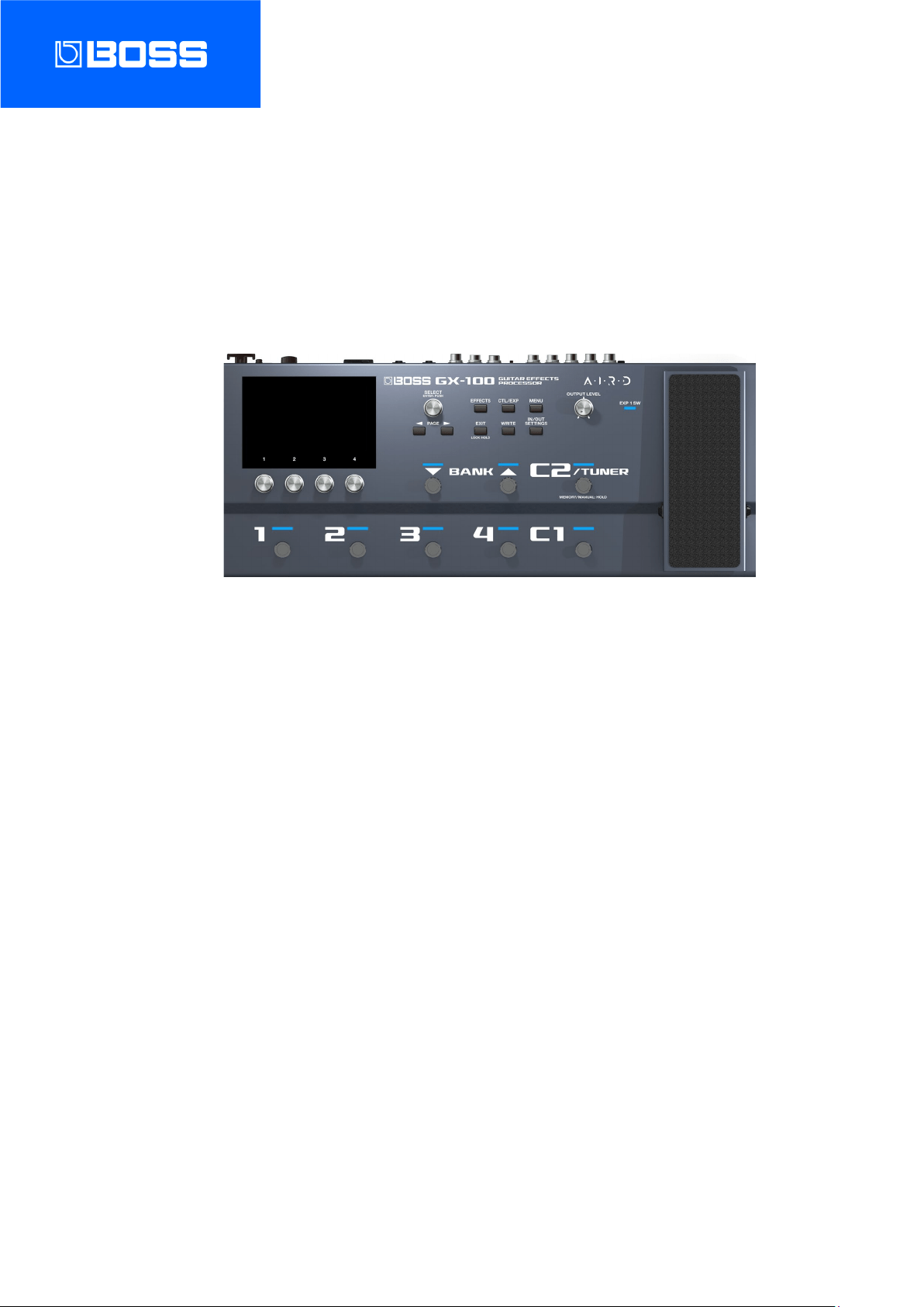
GX-100
Reference Manual

Table of contents
2
Table of contents
Getting Ready ............................................................................. 3
Connecting the Equipment .................................................... 3
Turning the Power On ............................................................. 5
Configuring the Input to Match the Instrument You
Connect .................................................................................... 6
Naming INPUT SETTINGS: 1–10 ................................................... 8
Specify the Type of Amplifier You Have Connected ......... 10
Adjusting the Volume ........................................................... 11
Using the Tuner ..................................................................... 12
Playing ........................................................................................ 14
Selecting a Memory .............................................................. 14
About the Play Screen .......................................................... 16
Assigning Favorite Parameters to [1]–[4] Knobs .................18
Selecting the Control Mode ................................................. 19
Editing: Effects ......................................................................... 23
Basic Procedure for Effect Editing ....................................... 23
Effect Placement .................................................................... 26
Switching Tones Without Interrupting the Sound .............31
Preserving the Tail of the Effect (Delay, Reverb, etc.) when
the Effect is Switched Off (Carryover) .....................................31
Saving a Memory ................................................................... 33
Editing: MENU .......................................................................... 35
Basic MENU Operations ........................................................ 35
Adjusting the Contrast (Brightness) of the Display .......... 37
Restoring the Factory Settings (Factory Reset) ................. 38
Turning Off the Auto Off Function ...................................... 40
Connecting to a Computer ................................................. 42
Connecting with an External MIDI Device .................... 43
Wireless Connection with a Mobile Device .................. 45
Attaching the BT-DUAL ......................................................... 45
Listening to Sound via Wireless Connection with a Mobile
Device ..................................................................................... 46
Controlling the GX-100 from a Mobile Device App ........... 48
Footswitch and Expression Pedal Settings ................... 49
Assigning a Function ............................................................. 49
ASSIGN SETTING............................................................................. 49
TARGET list ....................................................................................... 53
Virtual Expression Pedal System (Internal Pedal / Wave
Pedal) ................................................................................................. 66
Adjusting the Expression Pedal (Pedal Calibration).......... 67
Connecting External Pedals ................................................. 69
Looper ......................................................................................... 70
Error Message List ................................................................... 72
Main Specifications ................................................................ 73

Getting Ready
3
Getting Ready
This chapter explains how to get ready to play with the GX-100, including connecting the devices, the instruments to use, how to
make the basic settings suitable for your amp and so on.
Connecting the Equipment
Name of jack, port or
connector
Explanation
INPUT
Connect your guitar here.
OUTPUT L/MONO, R
Connect these to your guitar amp or mixer. If using a mono connection, use only the L/MONO jack.
PHONES
Connect your headphones here.
SEND/RETURN
Connect an external effect processor here.
You can connect an external effects processor between the SEND jack and RETURN jack, and use it as
one of the GX-100’s effects processors.
The sound that is input to SEND/RETURN within the effect chain will be output to the SEND jack. The
sound that is input via the RETURN jack will be input to SEND/RETURN within the effect chain.
[GND LIFT] switch
This should normally be set to OFF. Noise may occur due to a ground loop when you connect an
amp to the EXT LOOP (SEND/RETURN) jack. The noise may be eliminated if you switch to LIFT.
AMP CTL 1, 2
By connecting this to the channel switching jack of your guitar amp, you can switch channels from the
GX-100.
CTL3, 4/EXP2
You can control various parameters by connecting an expression pedal (Roland EV-5: sold separately) or
a footswitch (FS-5U, FS-6, FS-7: sold separately).
* Use only the specified expression pedal. Connecting expression pedals made by third-party
manufacturers may cause this unit to malfunction.

Getting Ready
4
Name of jack, port or
connector
Explanation
* Refer to 8.3. Connecting External Pedals(P.69) for the footswitch (FS-5U, FS-6 or FS-7, sold
separately) settings.
MIDI IN/OUT
Connect an external MIDI device here.
ă (USB COMPUTER)
Use a USB cable to connect to a computer and exchange audio/MIDI data between the GX-100 and the
computer.
DC IN
Connect the included AC adaptor here.
* Use the cord hook to secure the cord of the AC adaptor as shown in the illustration.
Ground terminal
Connect this to an external earth or ground. This should be connected when necessary.

Getting Ready
5
Turning the Power On
Turn the power on by following the steps below.
1.
Turn down the volume of the connected device.
2.
Connect your equipment to the OUTPUT jack(s).
3.
Connect the guitar to the INPUT jack.
4.
Turn on the power of the GX-100.
5.
Turn on the power of the amp(s).
To turn the power off, reverse the order.
Touch operations do not work correctly if your fingers or other objects are touching the screen while you turn on the power.
Don’t touch the screen with your fingers or any other objects while you turn on the power.

Getting Ready
6
Configuring the Input to Match the Instrument You Connect
This shows you how to set the type of instrument to connect (guitar/bass), and how to adjust the input level to match the output
level of your instrument.
You can save up to 10 instrument type and input level settings.
1.
Press the [IN/OUT SETTINGS] button.
2.
Touch <INPUT SETTINGS> on the screen (or press the [1] knob).
3.
Turn the [3] knob to select “GUITAR” or “BASS.”
4.
Turn the [4] knob while watching the level meter at the top right-hand part of the screen to adjust the
input level.

Getting Ready
7
Adjust the input levels so that the yellow peak indicator lights momentarily when a guitar is strummed strongly.
5.
To configure INPUT SETTINGS: 2–10, use the [1] knob to select the setting, and repeat steps 3–4.
The blue-colored setting that’s selected using the [SELECT] knob is the setting that’s currently used (SYSTEM).

Getting Ready
8
●
You can select INPUT SETTINGS for each memory. Select 1–10 or SYSTEM in the INPUT SETTING of MASTER for the last
component in the effect chain.
or
● You can name and save INPUT SETTINGS: 1–10. For details on the settings, refer to “Naming INPUT SETTINGS: 1–10(P.8) .”
Naming INPUT SETTINGS: 1–10
1.
Touch <NAME EDIT> on the screen.
2.
Use the PAGE [÷] [ø] buttons to move the cursor and use the [SELECT] knob to change the character.

Getting Ready
9
Operation
Function
Turn the [2] knob
Selects the type of characters
Turn the [3] knob
Switch uppercase/lowercase
Press the [3] knob
Delete one character (delete)
Turn the [SELECT] knob
Changes the character
Press the [4] knob
Insert one space (insert)
Press the [÷] [ø] buttons
Moves the cursor
Touch <DELETE ALL>
Delete all characters
3.
Touch <EXEC: [WRITE]> on the screen.
You can also write the name by pressing the [WRITE] button.
Getting Ready
10
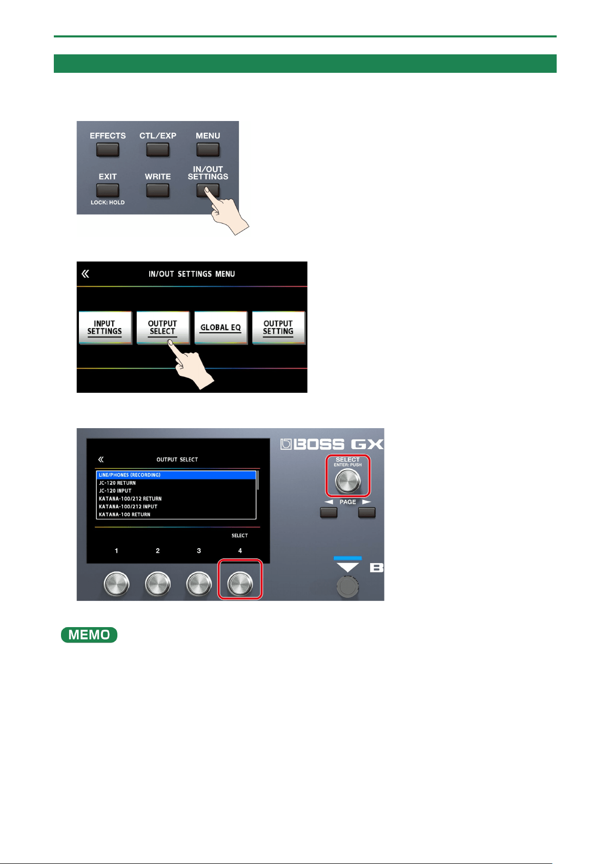
Specify the Type of Amplifier You Have Connected
1.
Press the [IN/OUT SETTINGS] button.
2.
Touch <OUTPUT SELECT> on the screen (or press the [2] knob).
3.
Turn the [4] knob or [SELECT] knob to select the item that you want to set.
* For details on the amp types, refer to the “GX-100 Parameter Guide.”
In order to take full advantage of the GX-100’s capabilities, we recommend that you connect to an input that is not affected by
a preamp; for example, you should connect to a RETURN jack rather than to a guitar input jack which is affected by the preamp
of your guitar amp.

Getting Ready
11
Adjusting the Volume
Use [OUTPUT LEVEL] knob to adjust the overall volume of the GX-100.
The output level is shown in the top right-hand part of the screen.

Getting Ready
12
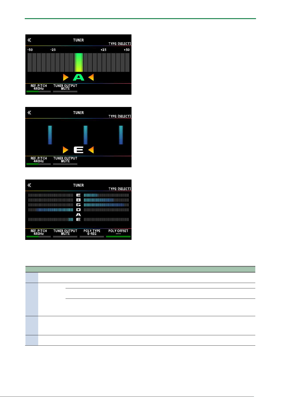
Using the Tuner
The GX-100 is equipped with a conventional monophonic tuner which lets you tune your instrument one string at a time, and a
polyphonic tuner which lets you play and tune all of your open strings simultaneously.
1.
Press the [C2/TUNER] switch.
The tuner screen appears.
You can also start the tuner from the play screen(P.16) by pressing the PAGE [÷] buttons.
Switching the tuner display
You can turn the [SELECT] knob to switch the tuner display.
Monophonic (normal)/polyphonic display
Monophonic (streaming)/polyphonic display
Getting Ready
13
Monophonic (normal) display
Monophonic (streaming) display
Polyphonic display
Tuner Settings
To make tuner settings, use knobs [1]–[4] located below the display.
Knob
Parameter
Value
Explanation
[1]
REF. PITCH
435–445 Hz (default: 440
Hz)
Specifies the reference pitch.
[2]
TUNER
OUTPUT
MUTE
Sound will not be output while tuning.
BYPASS
While tuning, the sound of the guitar being input to the GX-100 will be output
without change. All effects will be off.
THRU
Allows you to tune while hearing the current effect sound.
* Only for monophonic tuner.
[3]
POLY TYPE
6-REG, 6-DROP D, 7-REG,
7-DROP A、
4-B REG, 5-B REG
Selects the type of tuning for the polyphonic tuner.
[4]
POLY OFFSET
-5–-1, ----
Adjusts the reference pitch of the polyphonic tuner in semitone units relative
to standard tuning.
Playing
14
Playing
This section explains the basic operations when you are playing, including how to select the preset and user memories stored in
the GX-100, how to switch the individual effects on/off, the screens that are displayed and so on.
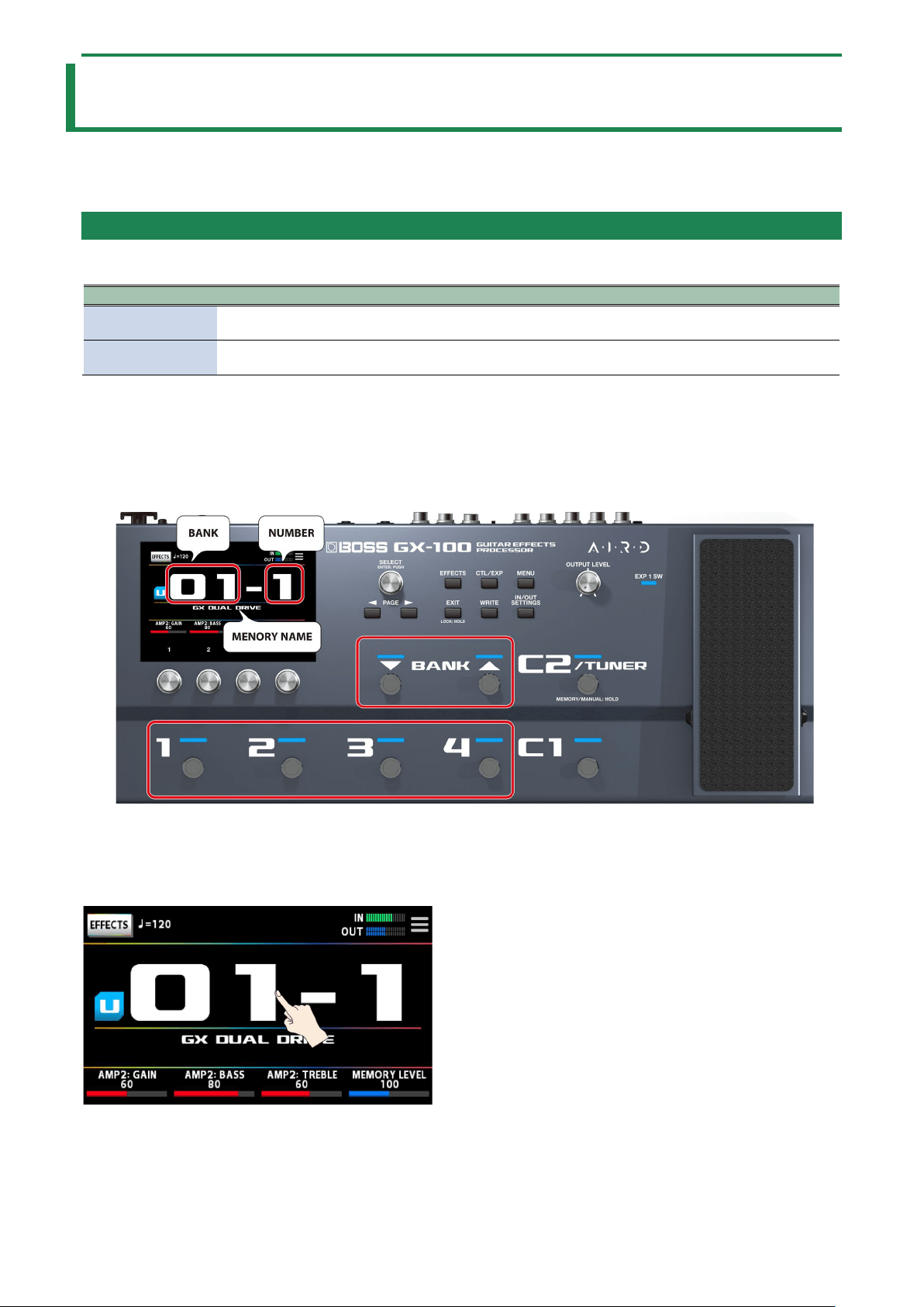
Selecting a Memory
A combination of effects and their settings is called a “memory.”
Memory type
Explanation
User memory (U01-
1–U50-4)
Can be overwritten
Preset memory (P01-
1–P25-4)
Cannot be overwritten. However, you can write a Preset memory into the User area, modify the settings
to your needs and store your modified version in the User area.
Selecting a memory using footswitches on the top panel
1.
Use the BANK [É] and BANK [Ç] switches to select a bank.
2.
Use the [1]–[4] switches to select a memory within the selected bank.
Selecting a memory using the touch panel
You can swipe the memory number horizontally or vertically to switch between memories on the play screen(P.16) that appears
when the power is turned on.

Playing
15
On other play screens, you can switch between memories by horizontally swiping the memory number and memory name at the
top of the screen.
You can also change memories by turning [SELECT] knob below the display.
Playing
16
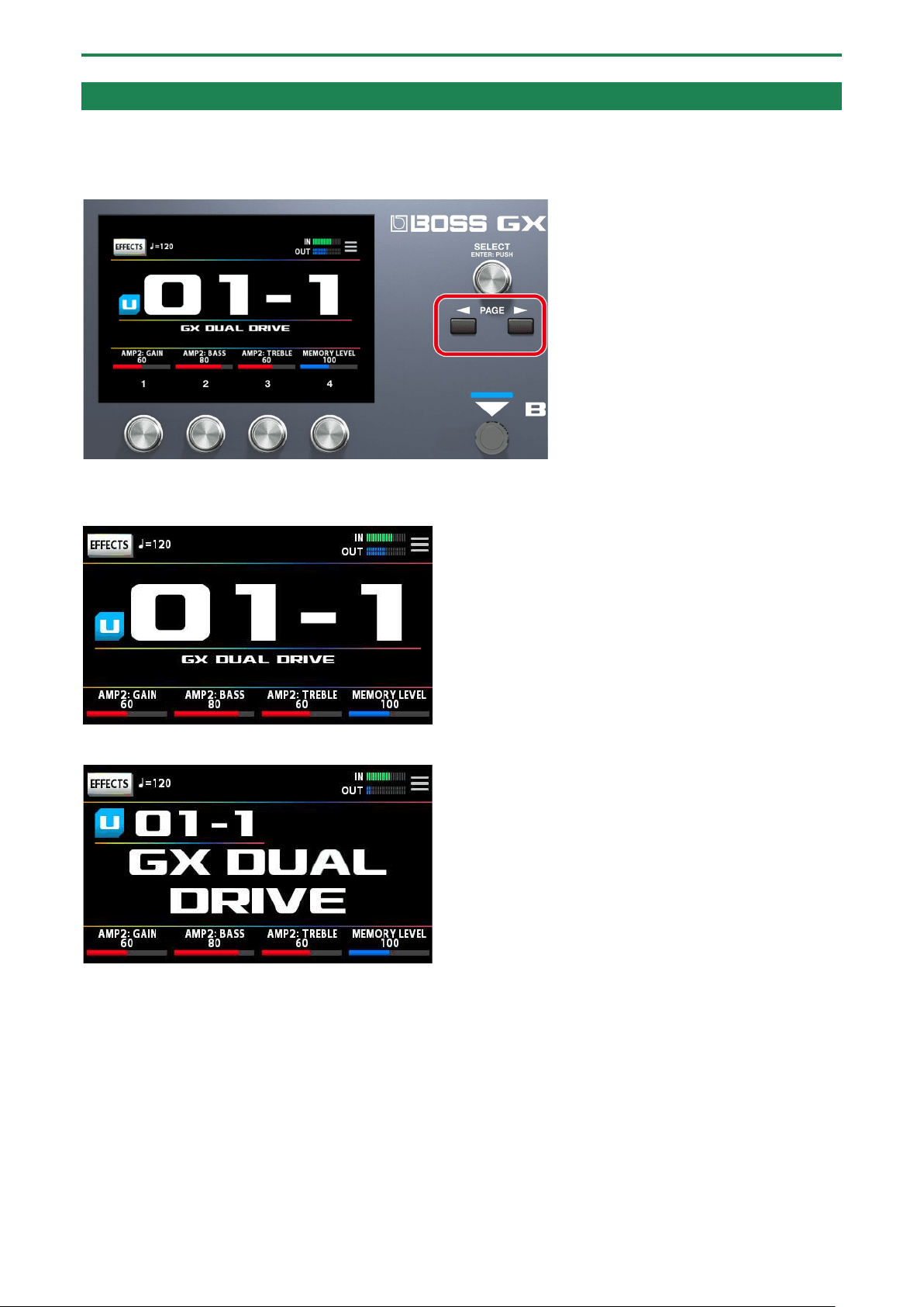
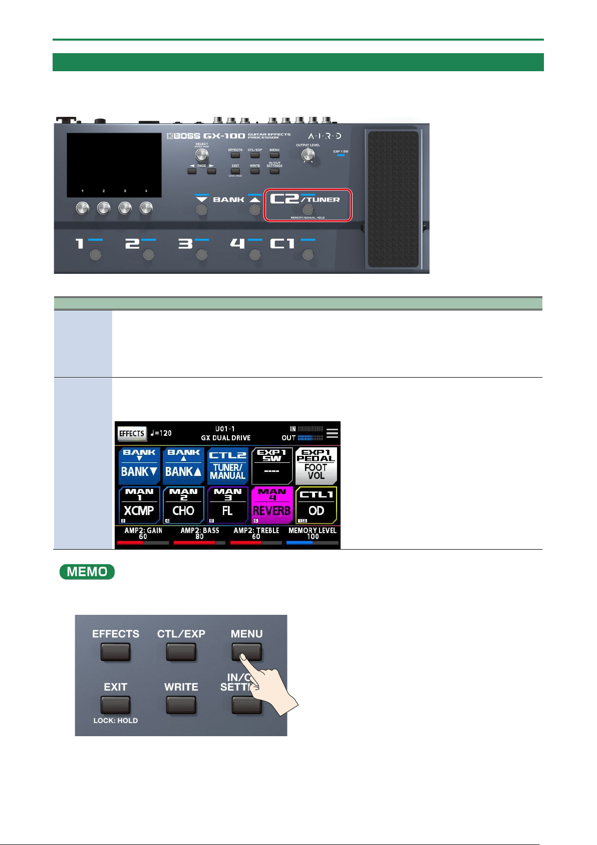
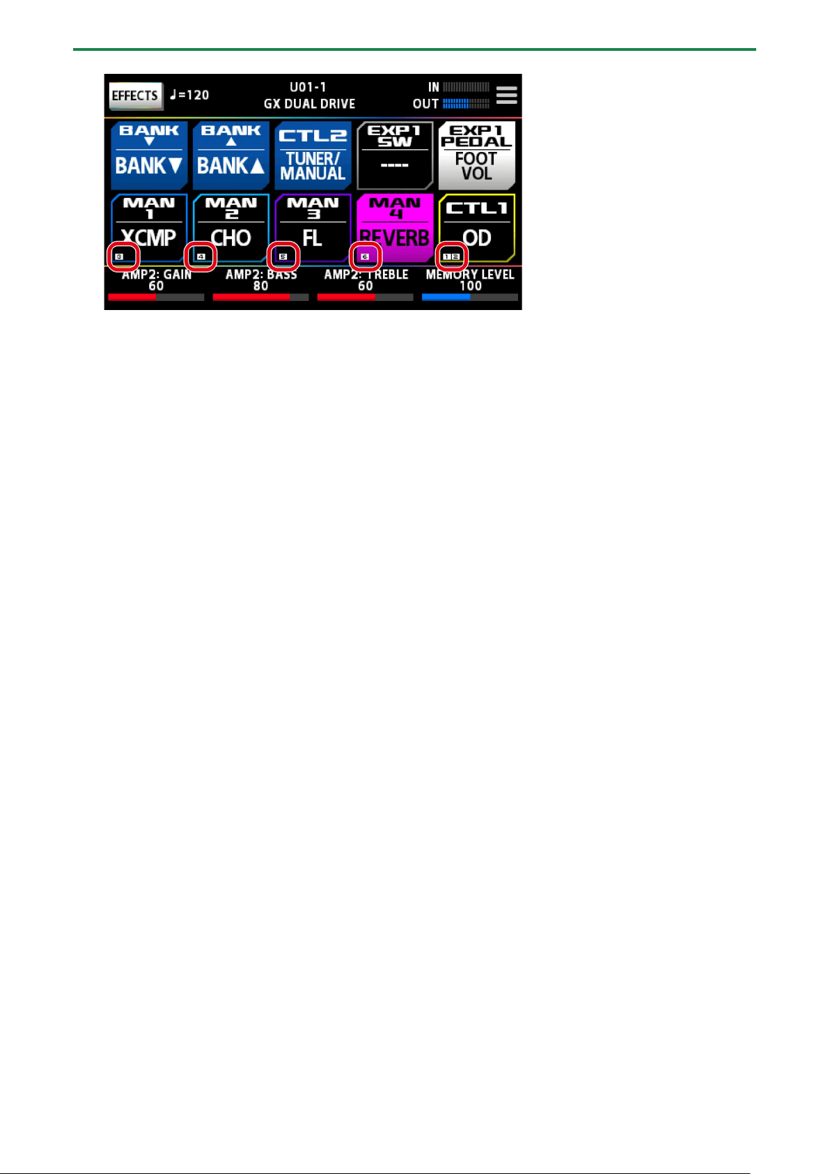
About the Play Screen
The screen that appears after you turn on the power is called the “Play screen.”
You can press the PAGE [÷] [ø] buttons to switch between display modes on the play screen (tuner Ð memory number display
mode Ð memory name display mode Ð control mode Ð chain mode).
Memory number display mode (the display mode used when turning on the power)
Memory name display mode
Control mode
You can touch the screen to switch between banks and memories, in the same way as when you use the footswitches on the top
panel.

Playing
17
Chain mode
Shows how the effects are arranged together for the selected memory.
* You can’t edit the effects chain using touch operations on the play screen when in chain mode. Touch the <EFFECTS> icon at
upper left, or press the [EFFECT] button to enter edit mode. For details, refer to “
3.1. Basic Procedure for Effect Editing(P.23).”
Tuner mode
From memory number display mode, press the [÷] button to view this mode.
Drag the respective parameters at the bottom of the screen to the left or right to change their values. You can also use the [1]–
[4] knobs below the screen to change the values.
Playing
18
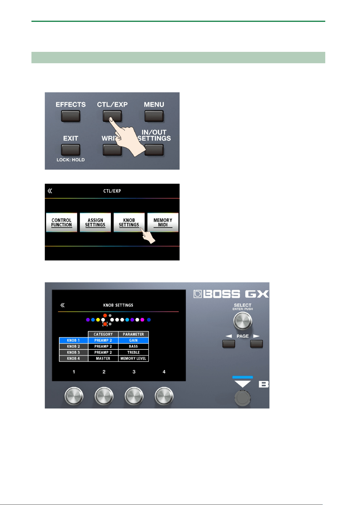
Assigning Favorite Parameters to [1]–[4] Knobs
Here’s how to assign the parameters that are controlled by knobs [1]–[4] when the play screen is shown.
1.
Press the [CTL/EXP] button.
2.
Touch <KNOB SETTINGS>.
3.
Turn the [SELECT] knob to select the knob you want to set. Turning the knob will move the selected item
vertically.
4.
Use the [2] and [3] knobs to edit the settings of the selection parameters (CATEGORY, TARGET) for each
knob.
For the parameters to set, refer to “8.1.2. TARGET list(P.53).”
Playing
19
Selecting the Control Mode
The control mode lets you choose how you want to operate the effects.
Long-press [C2] to switch the control mode.
Parameter
Explanation
MEMORY
(Memory
mode)
This mode lets you recall and use the memories that are saved in the unit.
Use number switches [1]–[4] to switch memories.
* With the factory settings, long-pressing the [C2/TUNER] switch puts the unit in manual mode.
* Even in memory mode, you can select functions other than memory recall.
MANUAL
(Manual
mode)
This mode lets you use number switches [1]–[4] to operate the functions that are assigned to them by each
memory or by the settings for the entire system.
The play screen switches to the manual mode display of the control mode screen when the unit is set to manual
mode.
You can also follow the steps in 4.1. Basic MENU Operations(P.35) to switch the control mode.
1.
Press the [MENU] button.

Playing
20
2.
Touch the <CONTROL MODE> icon on the screen.
3.
Touch the icons on the screen to select the control mode.
Assigning the switches in manual mode
In manual mode, the functions that are assigned to [1]–[4] switches can be changed as follows.
1.
Press the [CTL/EXP] button.
2.
Touch <ASSIGN SETTINGS>.
The ASSIGN SETTINGS screen appears.

Playing
21
3.
Turn the [SELECT] knob to select ASSIGN NUMBER (NUM).
Turning the knob will move the selected item vertically.
4.
Use knobs [1]–[4] to select parameters or edit the values.
Knob
Setting
Explanation
[1]
SOURCE
Selects the [1]–[4] switches (MAN 1–MAN 4) for which functions are to be assigned in manual mode.
[2]
MODE
Selects the operation mode for the footswitch you selected using the [1] knob.
TOGGLE: Toggles the setting on/off each time you press the footswitch.
MOMENT: The setting is normally off, but turns on whenever the footswitch is operated.
[3]
CATEGORY
Selects the effect to control from a footswitch.
[4]
PARAMETER
Select the parameter for the effect you selected using the [3] knob that you want to control with the
footswitch.
The ASSIGN NUMBER (NUM) that is assigned to each of the [1]–[4] switches is shown on the control mode screen.
Editing: Effects
23
Editing: Effects
This section explains how to arrange the effects, how to edit individual effects, how to store them in memory after editing and so
on.
Basic Procedure for Effect Editing
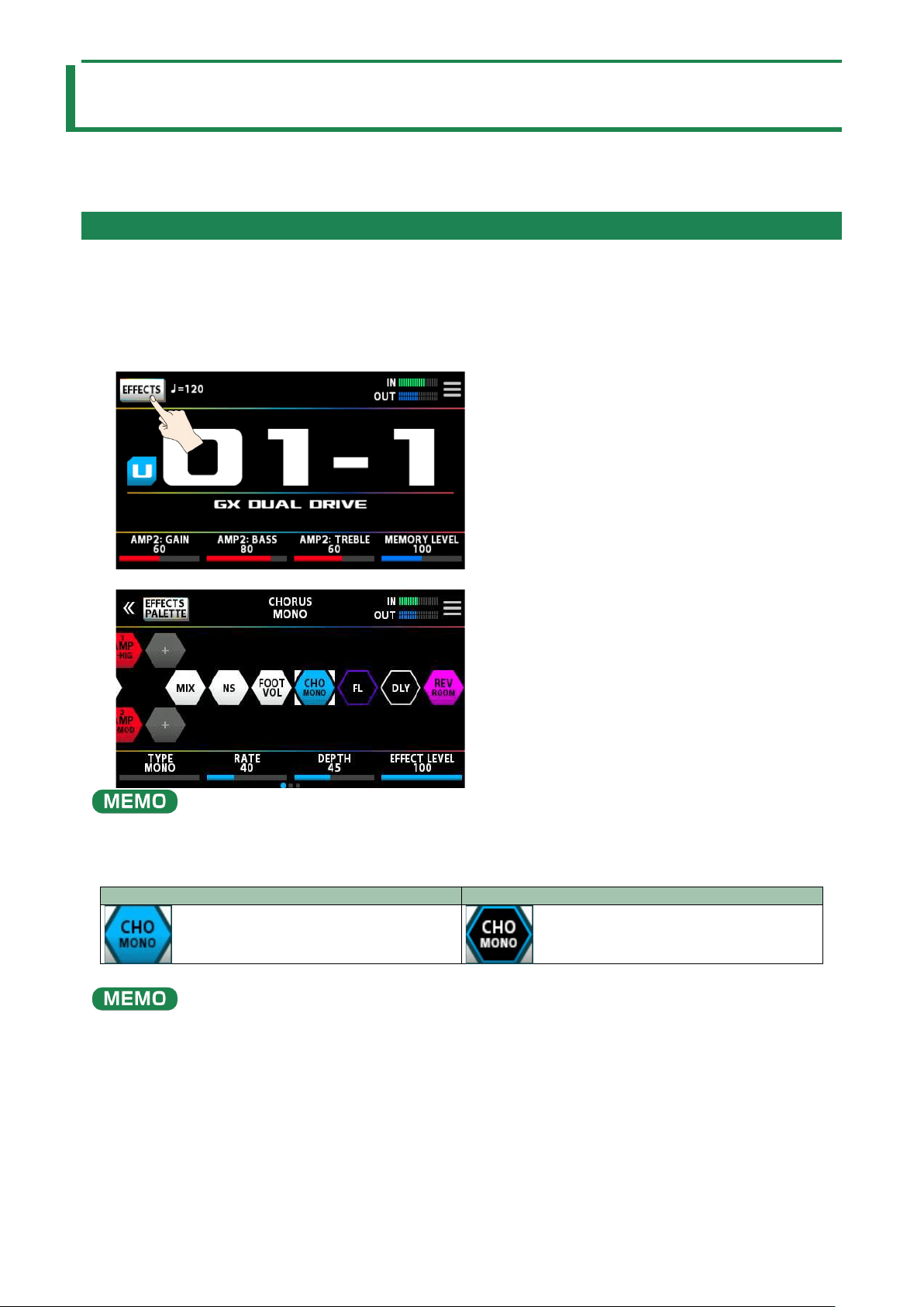
Effect chain screen
The effect screen shows all of the effects used by the selected memory, as well as the output, send/return arrangement (effect
chain) and so on. You can edit by selecting the icon of the effect that you want to edit from the effect chain.
1.
Touch <EFFECTS> in the upper left of the screen.
The effect chain screen is shown.
You can also bring this up by pressing the [EFFECTS] button on the top panel.
2.
Touch the icon of the effect you want to edit.
The effect toggles on/off each time you touch the icon.
On
Off
You can also toggle the effect on/off by pressing the [SELECT] knob.
3.
Drag the respective parameters at the bottom of the screen to the left or right to change their values.
Use the PAGE [÷] [ø] buttons to switch between the parameters that you want to edit. The current page is indicated in the
lower center of the screen.
Editing: Effects
24
* The number of parameters and pages differs depending on the effect.
You can also use knobs [1]–[4] to change the values that are shown at the bottom of the screen. To change a value in larger
steps, turn a knob while pressing it.
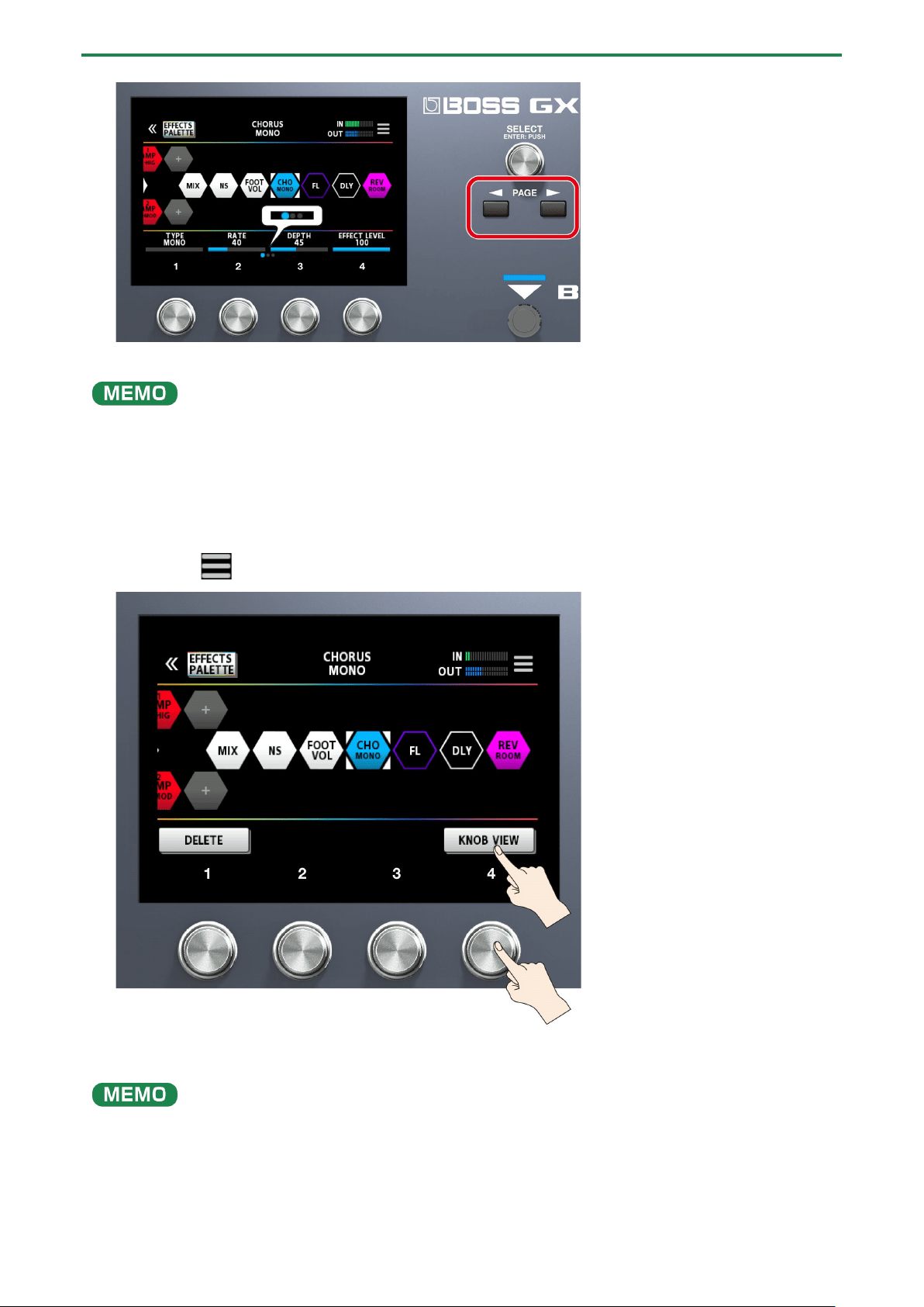
Edit screen
Displays all parameters that you can edit for each effect.
1.
Touch the icon of the effect you want to edit in the effect chain, shown in the center of the screen.
2.
Touch the mark at the top right-hand part of the screen.
3.
Touch <KNOB VIEW>. (Or press the [4] knob.)
The edit screen (KNOB VIEW) appears.
You can display the edit screen (KNOB VIEW) by touching the icon of the effect you want to edit in step 1, and then long-
pressing the [SELECT] button.
4.
Drag the parameter icons up and down to change their values.

Editing: Effects
25
Use the PAGE [÷] [ø] buttons to switch between the parameters that you want to edit. The current page is indicated in the
lower center of the screen.
Touch an effect name at the bottom of the screen to edit that effect.
Editing: Effects
26
Effect Placement
By moving the icons that represent the effects, send/return and so on, you can freely change the order in which the effects are
placed, or arrange them in parallel.
You can arrange up to 15 effects and functional devices such as DIVIDER/MIXER, LOOPER, SEND/RETURN and so on within the
effect chain.
Maximum number of effects and functional devices that can be placed
Type
Upper limit on effects that can be placed
Same effect
9
AMP
2
LOOPER
1
DIVIDER/MIXER
1
SEND/RETURN
1
Due to DSP capacity limits, you may not be able to insert or overwrite an effect, even when the number of connected effects
falls within the limits. If there isn’t enough DSP capacity, the icon for the effect you’re trying to newly place in the chain is
greyed out, and you cannot place the effect. To place a new effect, you must delete an existing effect.
Adding effects to the chain (insert)
1.
Touch <EFFECTS PALETTE>.
The icons representing all of the effects you can use on the GX-100 are shown in the top row (palette) of the screen.
The bass guitar effects are shown after the guitar effects.
2.
Drag the icon of the effects you like from the palette to the middle of the screen (the effect chain).
This example shows how to place the BOOST effect between X-COMP and OD.

Editing: Effects
27
3.
When the “+” icon appears, release the finger you’re using to drag the icon.
This places BOOST between X-COMP and OD.
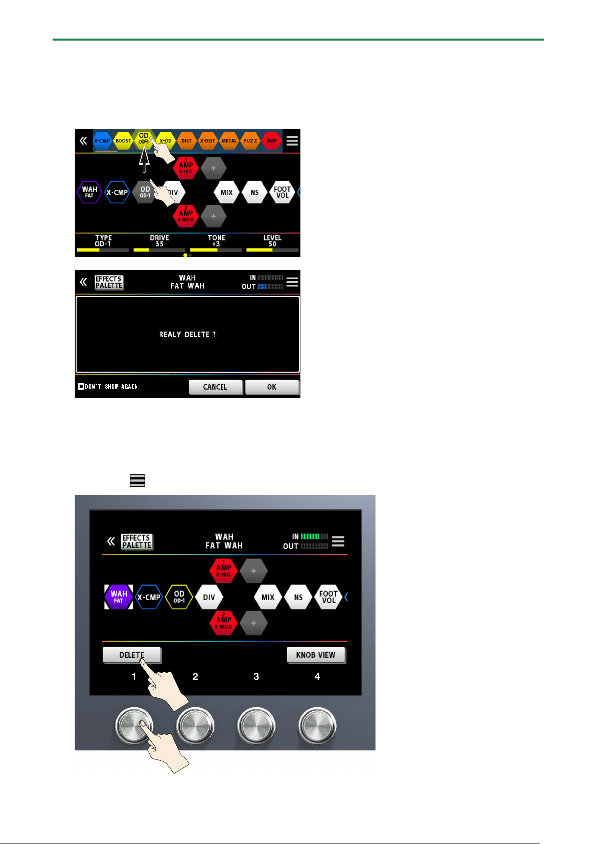
Replacing effects in the chain with other effects (overwrite)
1.
Touch <EFFECTS PALETTE>.
The icons representing all of the effects you can use on the GX-100 are shown in the top row of the screen.
2.
Drag an effect icon from the top row of the screen onto the top of the effect you want to replace.
In this example, we replace OD in the chain with BOOST.

Editing: Effects
28
A confirmation message appears once you release your finger.
3.
Touch <OK>.
The OD effect in the chain is now replaced with BOOST.
●
You can turn the [SELECT] knob to select the effect icons on the palette. You can also press the [SELECT] knob to insert an
effect after the icon you’ve selected in the effect chain.
● Press the [SELECT] knob while holding down the [EFFECTS] button to overwrite the icon you’ve selected in the effect
chain.
● Touch <ÂDON’T SHOW AGAIN> at the lower left of the confirmation screen, select the  check box and then touch <OK>
if you want to delete without seeing the confirmation message from next time.
Moving effects in the chain
1.
Hold down an icon and drag it from left to right to change the effect’s order in the chain.
With the effect icon selected, hold down and turn the [SELECT] knob to move the effect.
Editing: Effects
29
Deleting effects from the chain
1.
Hold down the icon of the effect you want to delete in the effect chain at the center of the screen, and
drag it to the palette at the top row on the screen.
2.
Remove your finger from the icon once the background of the effect in the palette is highlighted blue.
A confirmation message appears.
3.
Touch <OK> (or press the [4] knob).
To cancel, touch <CANCEL> or press the [3] knob.
You can also use the following method to delete an effect.
1.
Touch the icon of the effect you want to delete in the effect chain, shown in the center of the screen.
2.
Touch the mark at the top right-hand part of the screen.
Editing: Effects
30
3.
Touch <DELETE> (or press the [1] knob).
A confirmation message appears.
4.
Touch <OK> (or press the [4] knob).
To cancel, touch <CANCEL> or press the [3] knob.
Touch <
Â
DON’T SHOW AGAIN> at the lower left of the screen, select the
Â
check box and then touch <OK> if you want to
delete without seeing the confirmation message from next time.
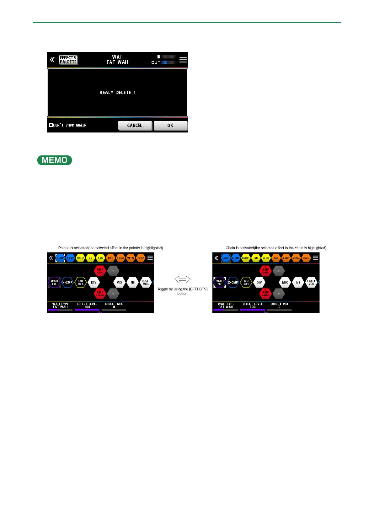
Rearranging effects by operating the buttons or knobs
You can use the buttons or knobs to insert, overwrite and delete effects, without using the touch panel.
Inserting
1.
Press the button to toggle between the palette and chain.
2.
Use the [SELECT] knob to select the effect just before the position where you want to add the effect from
the palette.
3.
Press the [EFFECTS] button to activate the palette.
4.
Use the [SELECT] knob to select the effect you want to place from the palette.
5.
Press the [SELECT] button.
The effect that you selected in the palette is placed after the effect you selected in the chain.
Overwriting
1.
Press the [EFFECTS] button to activate the palette.
2.
Use the [SELECT] knob to select the effect that you want to place from the palette into the chain.
3.
Press the [EFFECTS] button to activate the chain.
4.
Use the [SELECT] knob to select the effect that you want to replace with the effect that you selected in
the palette.
5.
Press the [EFFECTS] button to activate the palette again, and press the [SELECT] knob while holding
down the [EFFECTS] button.
The effect that you selected in the chain is replaced by the effect you selected in the palette.

Editing: Effects
31
Deleting
1.
Press the [EFFECTS] button to activate the chain.
2.
Use the [SELECT] knob to select the effect you want to delete.
3.
Hold down the [EXIT] button and press the [SELECT] knob.
The effect you selected in the chain is now deleted.
Switching Tones Without Interrupting the Sound
Using DIVIDER and MIXER within the same memory
Place the same type of effect in parallel and use DIVIDER to switch between channels A and B.
Example:
Switching from a clean sound that uses chorus and heavy delay to a high-gain, crunchy sound that uses a phaser and light delay.
The settings of the effect used before switching are placed in parallel with the settings used after switching.
Preserving the Tail of the Effect (Delay, Reverb, etc.) when the Effect is Switched Off (Carryover)
The function that preserves the tail of an effect (such as delay or reverb) even after the effect is switched off is called “carryover.”
Enabling carryover when switching memories
To enable the carryover of the delay or reverb (included in the memory that you used before switching) after you’ve switched to a
different memory, make the following settings.
● On the preceding and on the following memories, configure the effect chain to use the same effect, and use the same
arrangement. Set each effect type to be the same as well.
● On each memory, change the effect parameter settings and the on/off settings.
● Turn the CARRYOVER parameter in MASTER of the final component in the effect chain to “on.”
or

Editing: Effects
32
Enabling carryover when switching tones within a memory
When you use the switches within a single memory that were assigned in manual mode or by using CTRL FUNCTION to turn the
delay or reverb off, carryover is enabled once you turn on the individual CARRYOVER parameters for the delay or reverb in
question.
or

Editing: Effects
33
Saving a Memory
When you want to save a memory you have created, save it as a user memory by following the procedure below. If you do not
save the memory, the edited settings will be lost when you turn off the power or switch to another memory.
1.
Press the [WRITE] button.
2.
Touch <WRITE> (or press the [1] knob).
3.
Use knob [1] to select the save-destination (U01-1–U50-4).
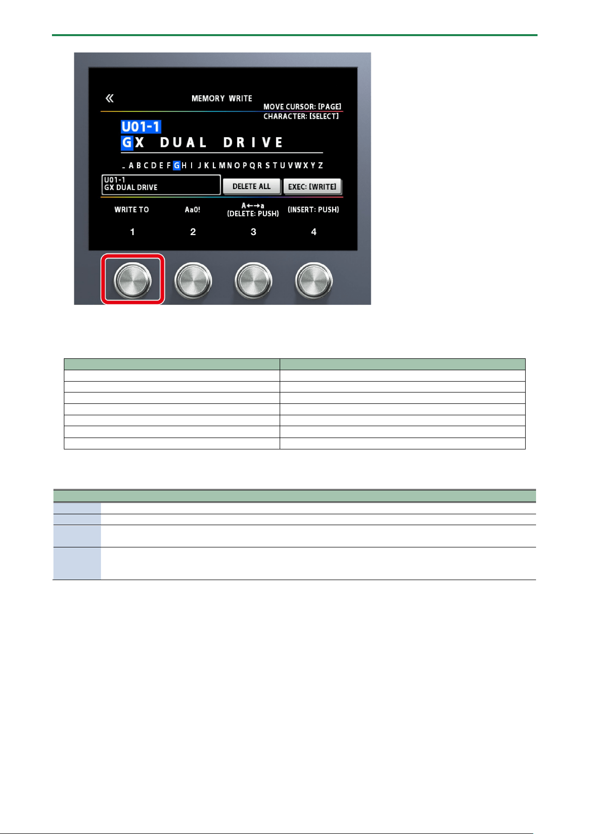
Editing: Effects
34
Hold down knob [1] and then turn it to move between banks.
You can use knobs [2]–[4] to edit the name.
To edit the memory name, use the PAGE [÷] [ø] buttons to move the cursor and use the [SELECT] knob to change the
character.
Operation
Function
Turn the [2] knob
Selects the type of characters
Turn the [3] knob
Switch uppercase/lowercase
Press the [3] knob
Delete one character (delete)
Turn the [SELECT] knob
Changes the character
Press the [4] knob
Insert one space (insert)
Press the [÷] [ø] buttons
Moves the cursor
Touch <DELETE ALL>
Delete all characters
4.
Touch <EXECUTE WRITE> on the screen. (Or press the [WRITE] button.)
List of WRITE MENU functions
Menu
Function
WRITE
Saves the memory you created.
EXCHANGE
On the GX-100, you can “swap” or exchange the positions of two User memories.
INITIALIZE
You can restore (initialize) each effect in a user memory to its standard settings. This is useful when you want to
create a new memory from scratch.
INSERT
You can insert a memory into any position of the user memories.
For example, if you insert memory U01-1 at U02-1, memory U02-1 and subsequent memories are shifted
(renumbered) backward by one. (Memory U02-1 becomes U02-2.)
Editing: MENU
35
Editing: MENU
This section explains how to make settings that are common to the entire GX-100 (system parameters).
Basic MENU Operations
For details on the parameter (SYSTEM parameter), refer to the “GX-100 Parameter Guide.”
1.
Press the [MENU] button.
2.
Touch the icon of the parameter you want to set.
A sub-menu may appear depending on the parameter, which you can also touch to set.
3.
Drag the parameter icons up and down to change their values.

Editing: MENU
36
You can also use the [1]–[4] knobs below the parameter icons to change the values.
Selecting menus with the buttons or knobs
You can use the buttons or knobs to select menus or sub-menus instead of using the touch panel.
1.
Turn the [SELECT] knob to select either the top row or the bottom row of the menu.
The menu items on the selected row are underlined.
2.
Press the [1]–[4] knobs to select the menu.

Editing: MENU
37
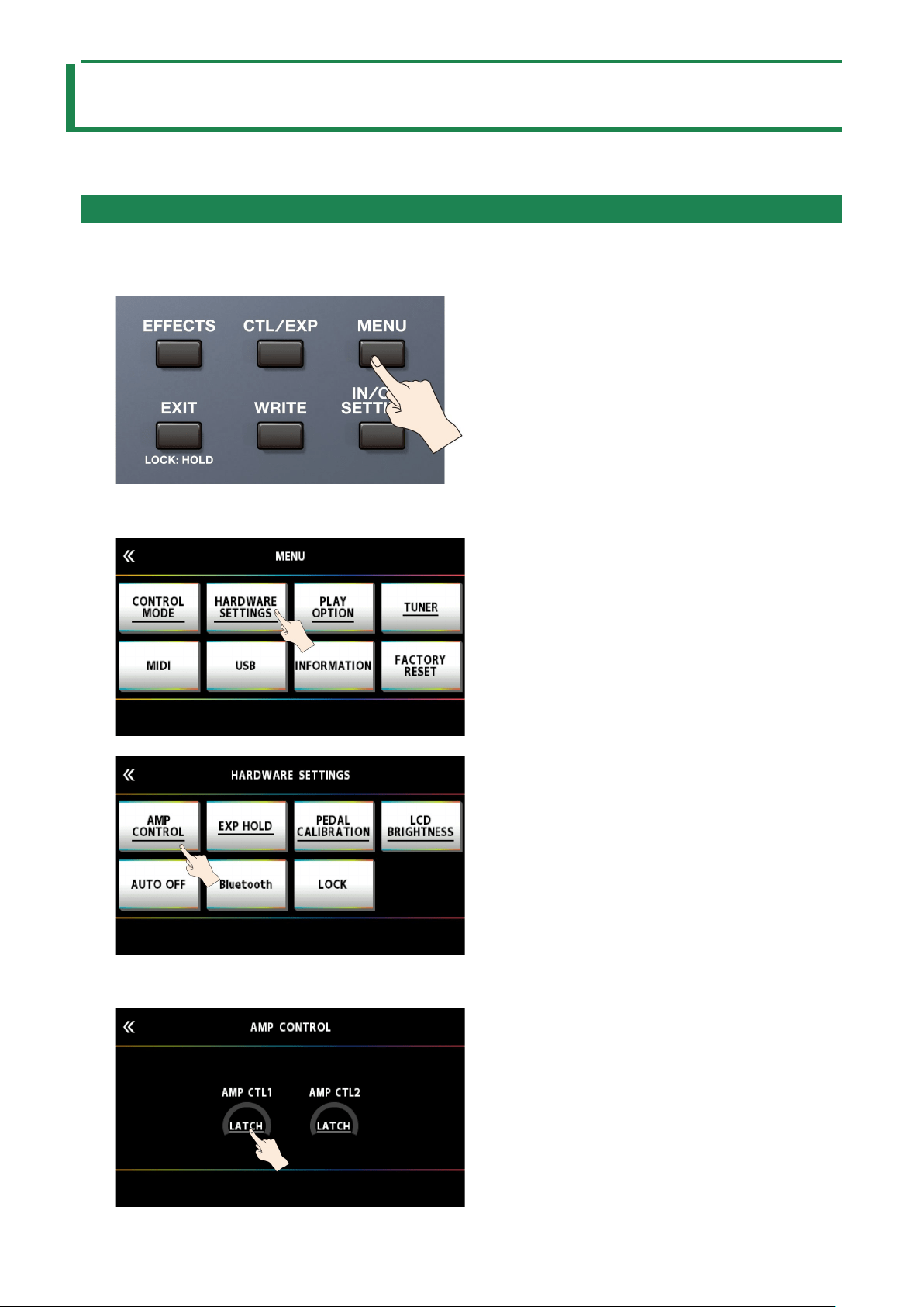
Adjusting the Contrast (Brightness) of the Display
You can adjust the brightness of the display.
1.
Press the [MENU] button.
2.
Touch <HARDWARE SETTINGS>.
3.
Touch <LCD BRIGHTNESS>.
4.
Drag the <LCD BRIGHTNESS> up and down to adjust the brightness.
Use either the [1]–[4] knobs below the screen or the [SELECT] knob to edit the value.
Editing: MENU
38
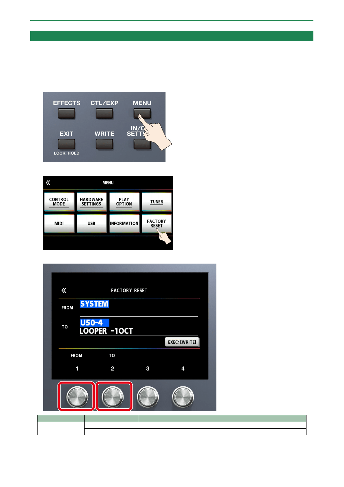
Restoring the Factory Settings (Factory Reset)
Restoring the GX-100’s settings to their original factory settings is referred to as “Factory Reset.” You can restore all of the settings
to their factory-set values, and you can also specify certain items to be reset.
* When you execute “Factory Reset,” the settings you made are lost. Save the data you need to your computer using the
dedicated software.
1.
Press the [MENU] button.
2.
Touch <FACTORY RESET>.
3.
Specify the factory reset range by using the [1], [2] knobs to set <FROM> and <TO>.
Parameter
Value
Explanation
FROM, TO
SYSTEM
System parameter settings
U01-1–U50-5
Settings for Memory Numbers U01-1–U50-4

Editing: MENU
39
You can also use the [1] knob below the screen to set the “FROM” value.
You can also use the [4] knob below the screen to set the “TO” value.
4.
Touch <EXEC: [WRITE]>.
A confirmation message appears.
Touch <OK> to execute the factory reset.
To cancel factory reset, touch <CANCEL>.
Once the Factory Reset is complete, you are returned to the Play screen.
Editing: MENU
40
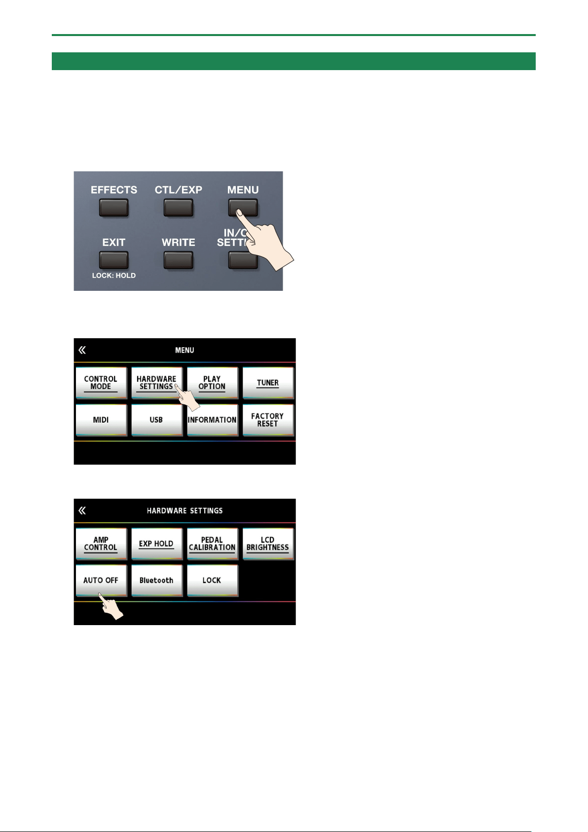
Turning Off the Auto Off Function
The GX-100 will turn off automatically when 10 hours have passed since you last played or operated the unit (Auto off function).
The display will show a message approximately 15 minutes before the power turns off.
With the factory settings, this function is turned “ON” (power-off in 10 hours). If you want to have the power remain on all the time,
turn it “OFF.”
1.
Press the [MENU] button.
2.
Touch <HARDWARE SETTINGS>.
3.
Touch <AUTO OFF>.
4.
Touch <OFF>.

Editing: MENU
41
The screen switches to the one shown below, and the function that automatically turns off the power is disabled.
5.
Press the [EXIT] button a number of times to return to the play screen.

Connecting to a Computer
42
Connecting to a Computer
By connecting the GX-100 to a computer via USB, you can do the following.
● Transmit and receive digital audio signals between the computer and the GX-100
● Edit and manage memories, and display the “GX-100 Parameter Guide” on a computer using the dedicated software
● Download memories from our dedicated BOSS TONE CENTRAL website
Ø
http://bosstonecentral.com/
Installing the USB Driver
You must install the USB driver before connecting to a computer.
Download the USB driver from the website shown below.
Install this special driver before making a USB connection. For further details, refer to the Readme.htm file that comes with the
download.
Ø
http://www.boss.info/support/
The program you need to use, and the steps you need to take to install the USB driver will differ depending on your computer
setup, so please carefully read and refer to the Readme.htm file that comes with the download.
Using the GX-100 as an Audio Interface
You can record the sound of the GX-100 on your computer, or have sound from your computer be output from the OUTPUT jacks.
* Refer to the instruction manual for the software you are using to learn how to switch the input source of the software.
Making use of the GX-100’s dedicated software
Please download the dedicated software from the website shown below. For details on how to use the software, refer to the
Readme.htm file that comes with the download.
Ø
http://www.boss.info/support/
Using the dedicated software allows you to do the following:
● Easily download memories from our BOSS TONE CENTRAL website.
● Edit memory settings
● You can assign a name to a memory.
● Organize memories in order and switch them around
● Back up memories and system settings, and return to the backed up settings
● You can bring up the manuals for this unit, including the “GX-100 Startup Guide,” the “GX-100 Reference Manual”
(this manual) and the “GX-100 Parameter Guide.”

Connecting with an External MIDI Device
43
Connecting with an External MIDI Device
On the GX-100, you can use MIDI to perform the following operations.
* For details on MIDI, refer to “GX-100Parameter Guide.”
Operations from the GX-100
Operation
Explanation
Transmit program
change messages
When you select a memory on the GX-100, the program change message specified by MEMORY MIDI is
also transmitted. The external MIDI device that receives this program change message will switch to the
corresponding settings.
Transmit control
change messages
When you operate the [C1]–[C2] switches or the footswitches or expression pedals connected to the CTL
3, 4/EXP 2 jack, this is output as a control change message. These messages can control parameters on an
external MIDI device.
Operations from an External MIDI Device
Operation
Explanation
Switch memory numbers
When the GX-100 receives a program change message from an external MIDI device, the GX-
100 will change memories.
Receiving Control Change
messages
The GX-100 can receive control change messages to control a specified parameter while you
perform.
Receive data
The GX-100 can receive data that is transmitted from another GX-100 unit, or data that was
saved on a MIDI sequencer.
Connection example
Settings
1.
Following the steps in “4.1. Basic MENU Operations(P.35),” select the sub-menu item in [MENU] Ó <MIDI>
Ó .
2.
If you’ve selected “MIDI SETTINGS” in the sub-menu, drag the parameter icon up/down to change the
value.
If you’ve selected “PROGRAM MAP” in the sub-menu, use knobs [1]–[4] to change the values.

Connecting with an External MIDI Device
44

Wireless Connection with a Mobile Device
45
Wireless Connection with a Mobile Device
Attach the Bluetooth® Audio MIDI Dual Adaptor (BT-DUAL, sold separately) to the GX-100 to wirelessly play back music on your
mobile device, or to edit the effects of this unit from the app on your mobile device.
* Note that the GX-100 does not offer Bluetooth functionality. You’ll need to attach the BT-DUAL (sold separately) to use
Bluetooth.
Attaching the BT-DUAL
Attach the BT-DUAL to the Bluetooth ADAPTOR jack of the GX-100.
1.
Power down the GX-100 and unplug the AC adaptor from the AC outlet.
2.
Remove the cover and screw from the Bluetooth ADAPTOR jack on the rear panel.
3.
Attach the BT-DUAL and fasten the screw that you removed in step 2 in place.
●
Be sure to use only the screw that was originally mounted on the Bluetooth ADAPTOR jack. If you use a different screw,
the unit may malfunction.
● Do not touch the circuitry or the jacks.
● After you have attached the BT-DUAL, check again whether it is properly installed.

Wireless Connection with a Mobile Device
46
Listening to Sound via Wireless Connection with a Mobile Device
Bluetooth® audio functionality
You can output music played from your Bluetooth audio-capable mobile device from the OUTPUT jacks or the PHONES jack of the
GX-100.
Registering a Mobile Device (Pairing)
“Pairing” involves registering the mobile device that you want to use with the GX-100 (making the two devices recognize each
other).
Here we’ll configure the settings so that music data saved on your mobile device can be played wirelessly via the GX-100.
The following explanation is only one example. For details, refer to the owner’s manual of your mobile device.
1.
Turn on the power of the GX-100.
2.
Place the mobile device that you want to connect close to the GX-100.
3.
Hold down the pairing button on the BT-DUAL until the Bluetooth indicator blinks rapidly.
4.
Turn on the Bluetooth function of the mobile device.
This explanation uses the iPhone as an example. For details, refer to the owner’s manual of your mobile device.
5.
Tap “GX-100 Audio” or “GX-100 MIDI” shown on the Bluetooth device screen of your mobile device.
This pairs the BT-DUAL with your mobile device. When pairing succeeds, “GX-100 Audio” is added to the list of “Paired
Devices” on your mobile device.
* If you don’t complete the pairing within a certain time, the Bluetooth indicator goes dark and the unit exits pairing standby
mode.
Connecting an Already-Paired Mobile Device
1.
With the BT-DUAL’s Bluetooth indicator off, press the pairing button.
2.
Turn on the Bluetooth function of the mobile device.

Wireless Connection with a Mobile Device
47
●
If you were unable to connect using the steps above, tap “GX-100 Audio,” displayed in the Bluetooth device screen of the
mobile device.
● To disconnect, press the pairing button on the BT-DUAL to make the Bluetooth indicator go dark, or turn off the mobile
device’s Bluetooth function.
Disabling Bluetooth Functionality
If you want to disconnect the Bluetooth connection between the BT-DUAL and your mobile device, disable Bluetooth
functionality.
1.
Press the pairing button on the BT-DUAL.
The Bluetooth indicator goes dark.

Wireless Connection with a Mobile Device
48
Controlling the GX-100 from a Mobile Device App
Use the “GX-100 Editor” app to edit effects and save settings on this unit.
For details on the GX-100 Editor, see the BOSS website.
https://www.boss.info/
Connecting to the App
Here are the settings to make in order to use an app on your mobile device.
* Make the connection from the app’s settings, not from your mobile device’s Bluetooth settings.
1.
Turn on the power of the GX-100.
2.
Place the mobile device that you want to connect close to the GX-100.
3.
Turn on the Bluetooth function of the mobile device.
When Bluetooth audio is connected, the Bluetooth indicator on the BT-DUAL lights up. Note that the unit has not finished
connecting with the app at this time.
This explanation uses the iPhone as an example. For details, refer to the owner’s manual of your mobile device.
4.
In the app’s settings, connect to GX-100 MIDI.
Do not tap “GX-100 AUDIO 1,” “GX-100 MIDI 1” or similar indications shown in the Bluetooth settings of your mobile
device.
Footswitch and Expression Pedal Settings
49
Footswitch and Expression Pedal Settings
You can assign a variety of functions to each of the top panel footswitches, the expression pedal (EXP1), and the expression pedal
or footswitch connected to the rear panel CTL 3, 4/EXP 2 jack.
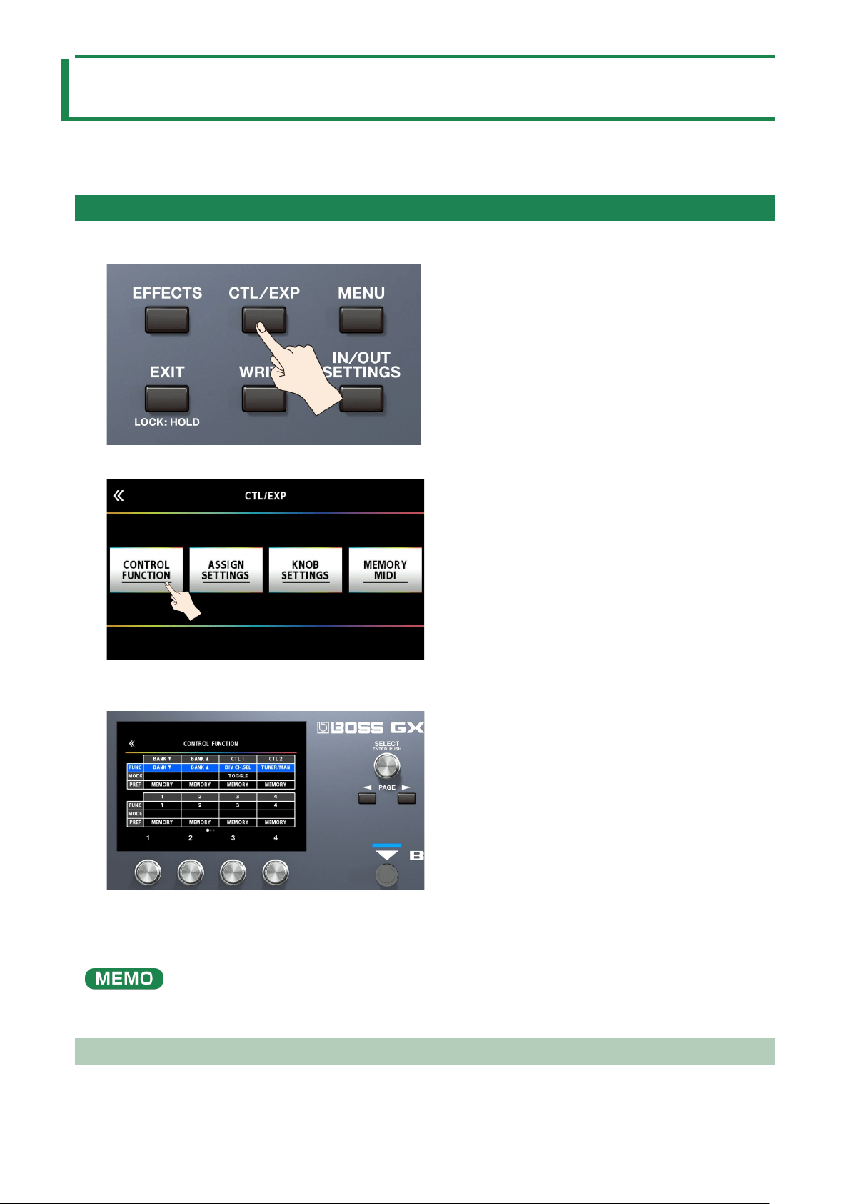
Assigning a Function
1.
Press the [CTL/EXP] button.
2.
Touch <CONTROL FUNCTION>.
3.
Turn the [SELECT] knob to select the item that you want to set.
Turning the knob will move the selected item vertically.
4.
Turn knobs [1]–[4] to edit the value of the item selected for each switch.
* The footswitch and expression pedal functions must be specified for each memory; however, if you set “PREF (PREFERENCE)”
to SYSTEM, all memories will use those functions in common.
The GX-100 lets you arrange multiple pedal effects in the effect chain like FOOT VOLUME, WAH and so on. In CONTROL
FUNCTION, the pedal effect placed at the beginning of the chain (or at “A CH” in DIV/MIX) is enabled.
ASSIGN SETTING
ASSIGN 1–20

Footswitch and Expression Pedal Settings
50
For each parameter, you can specify, in detail, which controller will control which parameter. You can create 20 sets of such
assignments.
1.
Press the [CTL/EXP] button.
2.
Touch <ASSIGN SETTINGS>.
The ASSIGN SETTINGS screen appears.
3.
Turn the [SELECT] knob to select ASSIGN NUMBER (NUM).
Turning the knob will move the selected item vertically.
4.
Use knobs [1]–[4] to select parameters or edit the values. Switch between pages using the PAGE [÷] [ø]
buttons.
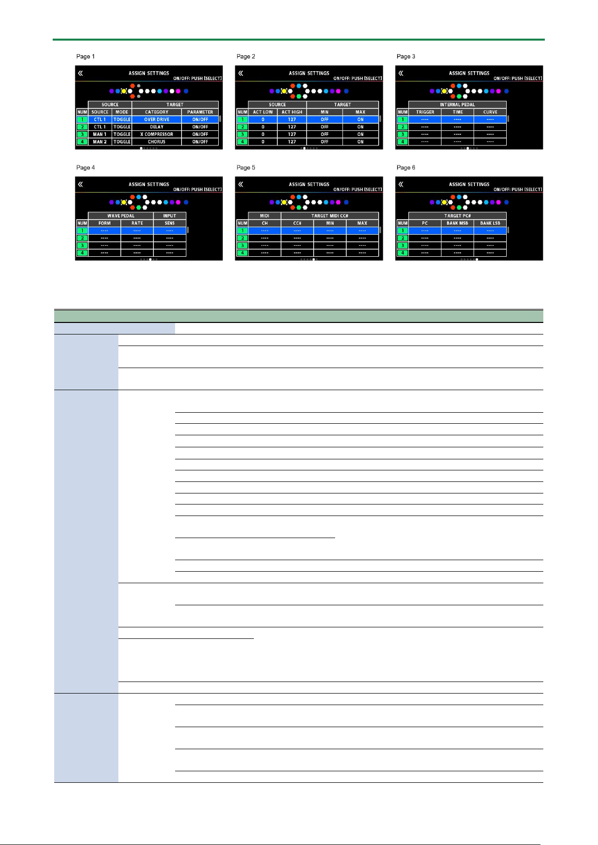
Footswitch and Expression Pedal Settings
51
5.
Press the [SELECT] knob to turn the selected ASSIGN NUMBER (NUM) on/off.
Parameter
Value
Explanation
SW
OFF, ON
Turns the ASSIGN 1–20 on/off.
TARGET
TARGET(P.53)
This selects the parameter to be changed.
MIN
This sets the minimum value for the range in which the parameter can change.
The value differs depending on the parameter assigned for TARGET parameter.
MAX
This sets the maximum value for the range in which the parameter can change. The value differs
depending on the parameter assigned for TARGET parameter.
SOURCE
SOURCE
NUM 1–NUM 4
Assigns the number switches [1]–[4] on this unit when set to memory
mode.
MAN 1–MAN 4
Assigns the number switches [1]–[4] on this unit when set to manual mode.
CUR NUM
Assigns the same number switch as the selected memory number.
BANK à
Assigns the GX-100’s BANK [Ç] switch.
BANK á
Assigns the GX-100’s BANK [É] switch.
CTL 1, CTL 2
Assigns the GX-100’s [C1]–[C2] switch.
CTL 3, CTL 4
Assigns the external footswitch connected to the CTL 3, 4/ EXP 2 jack.
EXP 1 SW
Assigns the GX-100’s [EXP 1] switch.
EXP 1
Assigns the GX-100’s expression pedal.
EXP 2
Assigns the external expression pedal connected to the CTL 3, 4/ EXP 2 jack.
INT PDL
Assigns the internal
pedal.
Refer to “8.1.3. Virtual Expression Pedal System
(Internal Pedal / Wave Pedal)(P.66)”
WAVE PDL
Assigns the wave
pedal.
INPUT
The assigned target parameter will change according to the input level.
CC# 1–31, 64–95
Control Change messages from an external MIDI device.
MODE
MOMENT
The normal state is Off (minimum value), with the switch On (maximum
value) only while the footswitch is depressed.
TOGGLE
The setting is toggled On (maximum value) or Off (minimum value) with
each press of the footswitch.
ACT LOW
0–126
You can set the controllable range for target parameters within the source’s
operational range.
Target parameters are controlled within the range set with ACT LOW and
ACT HIGH.
You should normally set ACT LOW to 0 and ACT HIGH to 127.
ACT HIGH
1–127
SENS
0–100
This adjusts the input sensitivity when INPUT is selected for SOURCE.
INTERNAL
PEDAL(P.66)
TRIGGER *1
MEM CHANGE
This is activated when a memory is selected.
EXP1 PDL-LOW
This is activated when the GX-100’s expression pedal is set to the minimum
position.
EXP1 PDL-MID
This is activated when the GX-100’s expression pedal is moved through the
middle position.
EXP1 PDL-HIGH
This is activated when the GX-100’s expression pedal is set to the maximum
position.
EXP1 SW
This is activated when the [EXP 1] switch is operated.

Footswitch and Expression Pedal Settings
52
Parameter
Value
Explanation
NUM1–NUM4
This is activated when the [1]–[4] switch is operated.
CUR NUM
This is activated when you operate the same number switch as the selected
memory number.
EXP 2
This is activated when an external expression pedal connected to the CTL 3,
4/ EXP 2 jack.
CTL 1, CTL 2
This is activated when the [C1]–[C2] switch is operated.
CTL 3, CTL 4
This is activated when an external footswitch connected to the CTL 3, 4/
EXP 2 jack is operated.
BANK à
This is activated when the BANK [Ç] switch is operated.
BANK á
This is activated when the BANK [É] switch is operated.
CC#1–31, 64–95
This is activated when a control change is received.
TIME *1
0–100
This specifies the time over which the internal pedal will move from the
toe-raised position to the toe-down position.
CURVE *1
LINEAR
SLOW RISE
FAST RISE
WAVE
PEDAL(P.66)
FORM *2
SAW
TRI
SINE
RATE *2
0–100,
BPM ŀ–Ō
This determines the time spend for one cycle of the assumed EXP Pedal.
* When set to BPM, the value of each parameter will be set according to the value of the
“MASTER BPM” specified for each memory. This makes it easier to achieve effect sound
settings that match the tempo of the song.
* If, due to the tempo, the time is longer than the range of allowable settings, it is then
synchronized to a period either 1/2 or 1/4 of that time.
MIDI
CH *3 *4
SYSTEM
Transmits a message on the MIDI channel specified by the parameter TX
CHANNEL in “MIDI SETTING.”
1–16
The message is transmitted on the specified MIDI channel.
TARGET MIDI
CC# *3
CC#
0–127
The message is transmitted using the specified controller number.
MIN
0–127
Selects the minimum value of the transmitted CC# message.
MAX
0–127
Selects the maximum value of the transmitted CC# message.
TARGET MIDI
PC# *4
PC#
1–128
Specifies the program number that is transmitted.
MSB
OFF, 0–127
Specifies the bank select MSB that is transmitted. If this is OFF, the bank
select MSB is not transmitted.
LSB
OFF, 0–127
Specifies the bank select LSB that is transmitted. If this is OFF, the bank
select LSB is not transmitted.
*1 The INTERNAL PEDAL TRIGGER, INTERNAL PEDAL TIME, and INTERNAL PEDAL CURVE parameters are enabled when the SOURCE
parameter is set to INT PEDAL.
*2 The WAVE PEDAL FORM and WAVE PEDAL RATE parameters are enabled when the Source parameter is set to WAVE PEDAL.
*3 The MIDI CH, TARGET MIDI CC# parameters are enabled when the TARGET is set to MIDI CC.
*4 The MIDI CH, TARGET MIDI PC# parameters are enabled when the TARGET is set to MIDI PC.

Footswitch and Expression Pedal Settings
53
Making Assignments from the Effect Edit Screen (Quick Assign)
In the effect edit screen(P.23), you can select an effect parameter and assign that parameter to the switch of your choice.
1.
Touch <EFFECTS> in the upper left of the screen (or press the [EFFECTS] button.
2.
Touch the icon of the effect you want to edit.
3.
Long-press the knob [1]–[4] for the parameter that you want to assign.
The ASSIGN SETTINGS screen appears.
The display automatically jumps to the ASSIGN NUMBER (NUM) that’s off.
4.
Press [SELECT] knob to turn the SW on.
5.
Turn knobs [2]–[4] to edit parameters.
If necessary, use the PAGE [÷] [ø] buttons to switch between pages of settings.
Use SOURCE to specify the pedal or MIDI message that you will operate.
TARGET list

Footswitch and Expression Pedal Settings
54
CATEGORY
TARGET
COMPRESSOR
ON/OFF
TYPE
SUSTAIN
ATTACK
LEVEL
TONE
DIRECT MIX
X-COMPRESSOR
ON/OFF
SUSTAIN
ATTACK
LEVEL
TONE
RATIO
DIRECT MIX
BOOSTER
ON/OFF
TYPE
BOOST
TONE
LEVEL
BOTTOM
DIRECT MIX
SOLO SW
SOLO LEVEL
OVER DRIVE
ON/OFF
TYPE
DRIVE
TONE
LEVEL
BOTTOM
DIRECT MIX
SOLO SW
SOLO LEVEL
X OVER DRIVE
ON/OFF
DRIVE
TONE
BOTTOM
LEVEL
DIRECT MIX
SOLO SW
SOLO LEVEL
DISTORTION
ON/OFF
TYPE
DIST
TONE
EFFECT LEVEL
BOTTOM
DIRECT MIX
SOLO SW
SOLO LEVEL
X-DISTORTION
ON/OFF
DRIVE
TONE
BOTTOM
LEVEL
DIRECT
SOLO SW
SOLO LEVEL
METAL DISTORTION
ON/OFF
TYPE
DRIVE
TONE
LEVEL
BOTTOM

Footswitch and Expression Pedal Settings
55
CATEGORY
TARGET
DIRECT MIX
SOLO SW
SOLO LEVEL
FUZZ
ON/OFF
TYPE
FUZZ
TONE
LEVEL
BOTTOM
DIRECT MIX
SOLO SW
SOLO LEVEL
PREAMP
ON/OFF
TYPE
GAIN
LEVEL
BASS
MIDDLE
TREBLE
PRESENCE
GAIN SW
SOLO SW
SOLO LEVEL
BRIGHT SW
SAG
RESONANCE
SP TYPE
DIRECT MIX
MIC TYPE
MIC DISTANCE
MIC POSITION
MIC LEVEL
PARAMETRIC EQUALIZER
ON/OFF
LOW GAIN
HIGH GAIN
LEVEL
LOW-MID FREQ
LOW-MID Q
LOW-MID GAIN
HIGH-MID FREQ
HIGH-MID Q
HIGH-MID GAIN
LOW CUT
HIGH CUT
GRAPHIC EQUALIZER
ON/OFF
31.5 Hz
63 Hz
125 Hz
250 Hz
500 Hz
1 kHz
2 kHz
4 kHz
8 kHz
16 kHz
LEVEL
CHORUS
ON/OFF
TYPE
DIRECT LEVEL
RATE
DEPTH
EFFECT LEVEL
LOW CUT
Footswitch and Expression Pedal Settings
56
CATEGORY
TARGET
HIGH CUT
PRE-DELAY
WAVEFORM
1: RATE
1: DEPTH
1: EFFECT LEVEL
1: PRE-DELAY
1: WAVEFORM
1: LOW CUT
1: HIGH CUT
2: RATE
2: DEPTH
2: EFFECT LEVEL
2: PRE-DELAY
2: WAVEFORM
2: LOW CUT
2: HIGH CUT
OUTPUT MODE
PRIME CHORUS
ON/OFF
RATE
DEPTH
EFFECT LEVEL
PRE-DELAY
WAVEFORM
LOW CUT
HIGH CUT
SWEETNESS
BELL
OUTPUT MODE
FLANGER
ON/OFF
RATE
DEPTH
RESONANCE
MANUAL
STEP RATE
LOW CUT
HIGH CUT
EFFECT LEVEL
PRIME FLANGER
ON/OFF
RATE
DEPTH
RESONANCE
MANUAL
TURBO
WAVE FORM
STEP RATE
SEPARATION
EFFECT LEVEL
LOW DAMP
HIGH DAMP
DIRECT MIX
LOW CUT
HIGH CUT
PHASER
ON/OFF
STAGE
RATE
DEPTH
RESONANCE
MANUAL
STEP RATE
EFFECT LEVEL
DIRECT MIX
SCRIPT PHASER
ON/OFF
Footswitch and Expression Pedal Settings
57
CATEGORY
TARGET
RATE
DEPTH
EFFECT LEVEL
DIRECT MIX
PRIME PHASER
ON/OFF
STAGE
RATE
DEPTH
RESONANCE
MANUAL
WAVE FORM
STEP RATE
BI-PHASE
SEPARATION
LOW DAMP
HIGH DAMP
LOW CUT
HIGH CUT
EFFECT LEVEL
DIRECT MIX
CLASSIC VIBE
ON/OFF
MODE
RATE
DEPTH
LEVEL
ROTARY
DIRECT MIX
SPEED SELECT
SLOW RATE
FAST RATE
EFFECT LEVEL
RISE TIME
FALL TIME
MIC DISTANCE
ROTOR/HORN
DRIVE
DIRECT MIX
VIBRATO
ON/OFF
RATE
DEPTH
TRIGGER
RISE TIME
EFFECT LEVEL
PRIME VIBRATO
ON/OFF
RATE
DEPTH
COLOR
EFFECT LEVEL
TRIGGER
RISE TIME
DIRECT MIX
TREMOLO
ON/OFF
RATE
DEPTH
WAVE FORM
EFFECT LEVEL
TRIGGER
RISE TIME
DIRECT MIX
PAN
ON/OFF
RATE
DEPTH
WAVE FORM
EFFECT LEVEL

Footswitch and Expression Pedal Settings
58
CATEGORY
TARGET
DIRECT MIX
RING MODULATOR
ON/OFF
INTELLIGENT
FREQUENCY
MOD RATE
MOD DEPTH
EFFECT LEVEL
DIRECT MIX
PITCH SHIFTER
ON/OFF
VOICE
DIRECT LEVEL
1: PITCH
1: MODE
1: FINE
1: PRE-DELAY
1: LEVEL
1: FEEDBACK
2: PITCH
2: MODE
2: FINE
2: PRE-DELAY
2: LEVEL
HARMONIST
ON/OFF
VOICE
1: HARMONY
1: LEVEL
1: PRE-DELAY
1: FEEDBACK
2: HARMONY
2: LEVEL
2: PRE-DELAY
DIRECT LEVEL
1: C
1: D³
1: D
1: E³
1: E
1: F
1: F´
1: G
1: A³
1: A
1: B³
1: B
2: C
2: D³
2: D
2: E³
2: E
2: F
2: F´
2: G
2: A³
2: A
2: B³
2: B
OVERTONE
ON/OFF
LOWER LEVEL
UPPER LEVEL
UNISON LEVEL
DIRECT LEVEL
DETUNE
OUTPUT MODE
Footswitch and Expression Pedal Settings
59
CATEGORY
TARGET
LOW
HIGH
OCTAVE
ON/OFF
-2 OCT
-1 OCT
DIRECT LEVEL
POLY OCTAVE
ON/OFF
RANGE
OCTAVE LEVEL
DIRECT LEVEL
DELAY
ON/OFF
TIME
FEEDBACK
HIGH CUT
EFFECT LEVEL
DIRECT LEVEL
HIGH CUT
BPM
CARRYOVER
DELAY PLUS
ON/OFF
TYPE
DIRECT LEVEL
MOD RATE
MOD DEPTH
DUCK SENS
DUCK PRE DEPTH
DUCK POST DEPTH
CARRYOVER
TIME
FEEDBACK
EFFECT LEVEL
HIGH CUT
TAP TIME
AUTO TRIGGER
MODE
1: TYPE
1: TIME
1: FEEDBACK
1: EFFECT LEVEL
1: HIGH CUT
2: HIGH CUT
2: TYPE
2: TIME
2: FEEDBACK
2: EFFECT LEVEL
ANALOG DELAY
ON/OFF
TYPE
TIME
FEEDBACK
EFFECT LEVEL
DIRECT LEVEL
HIGH CUT
MOD RATE
MOD DEPTH
DUCK SENS
DUCK PRE
DUCK POST
CARRYOVER
SPACE ECHO
ON/OFF
TIME
FEEDBACK
EFFECT LEVEL
DIRECT LEVEL

Footswitch and Expression Pedal Settings
60
CATEGORY
TARGET
HIGH CUT
MOD RATE
MOD DEPTH
DUCK SENS
DUCK PRE
DUCK POST
HEAD
WOW FLUTTER
CARRYOVER
SHIMMER DELAY
ON/OFF
TIME
FEEDBACK
EFFECT LEVEL
DIRECT LEVEL
HIGH CUT
MOD RATE
MOD DEPTH
DUCK SENS
DUCK PRE
DUCK POST
PITCH
PITCH BALANCE
PITCH FEEDBACK
CARRYOVER
TERA ECHO
ON/OFF
MODE
SPREAD TIME
FEEDBACK
EFFECT LEVEL
TONE
DIRECT LEVEL
TRIGGER
CARRYOVER
TWIST
ON/OFF
MODE
TRIGGER
LEVEL
RISE TIME
FALL TIME
FADE TIME
CARRYOVER
WARP
ON/OFF
TIME
TRIGGER
LEVEL
CARRYOVER
REVERB
ON/OFF
TYPE
TIME
PRE-DELAY
EFFECT LEVEL
DENSITY
LOW CUT
HIGH CUT
DIRECT LEVEL
CARRYOVER
REVERB PLUS
ON/OFF
TYPE
TIME
TONE
EFFECT LEVEL
DENSITY
PRE-DELAY

Footswitch and Expression Pedal Settings
61
CATEGORY
TARGET
LOW CUT
HIGH CUT
LOW DAMP
HIGH DAMP
MOD RATE
MOD DEPTH
DUCK SENS
DUCK PRE
DUCK POST
DIRECT LEVEL
CARRYOVER
SHIMMER REVERB
ON/OFF
TIME
TONE
EFFECT LEVEL
DENSITY
PRE-DELAY
LOW CUT
HIGH CUT
LOW DAMP
HIGH DAMP
MOD RATE
MOD DEPTH
DUCK SENS
DUCK PRE
DUCK POST
DIRECT LEVEL
1: PITCH
2: PITCH
1: LEVEL
2: LEVEL
CARRYOVER
AC GUITAR SIM
ON/OFF
BODY
LOW
HIGH
LEVEL
AC RESONANCE
ON/OFF
TYPE
RESONANCE
TONE
LEVEL
SLOW GEAR
ON/OFF
SENS
RISE TIME
LEVEL
DEFRETTER
ON/OFF
SENS
DEPTH
TONE
EFFECT LEVEL
ATTACK
RESONANCE
DIRECT MIX
TOUCH WAH
ON/OFF
FILTER MODE
POLARITY
SENS
FREQUENCY
RESONANCE
DECAY
EFFECT LEVEL
DIRECT MIX

Footswitch and Expression Pedal Settings
62
CATEGORY
TARGET
S-BEND
ON/OFF
TRIGGER
PITCH
RISE TIME
FALL TIME
WAH
ON/OFF
WAH TYPE
PEDAL POSITION
PEDAL MIN
PEDAL MAX
EFFECT LEVEL
DIRECT MIX
PEDAL BEND
ON/OFF
PITCH MIN
PITCH MAX
PEDAL POSITION
EFFECT LEVEL
DIRECT MIX
FOOT VOLUME
ON/OFF
PEDAL POSITION
VOLUME MIN
VOLUME MAX
CURVE
NOISE SUPPRESSOR
ON/OFF
THRESHOLD
RELEASE
DETECT
DIVIDER
MODE
CH SELECT
MIX MODE
A: DYNAMIC
A: DYNAMIC SENS
A: FILTER
A: CUTOFF FREQ
B: DYNAMIC
B: DYNAMIC SENS
B: FILTER
B: CUTOFF FREQ
MIXER
MODE
A LEVEL
B LEVEL
A/B BALANCE
SPREAD
SEND/RETURN
ON/OFF
MODE
SEND LEVEL
RETURN LEVEL
ADJUST
INVERT
LOOP
LOOP LEVEL
BASS X-COMP
ON/OFF
ATTACK
LEVEL
TONE
RATIO
DIRECT MIX
THRESHOLD
BASS OVER DRIVE
ON/OFF
DRIVE
TONE
EFFECT LEVEL
BOTTOM
DIRECT MIX

Footswitch and Expression Pedal Settings
63
CATEGORY
TARGET
SOLO SW
SOLO LEVEL
X BASS OVERDRIVE
ON/OFF
DRIVE
TONE
EFFECT LEVEL
BOTTOM
DIRECT MIX
SOLO SW
SOLO LEVEL
BASS DISTORTION
ON/OFF
TYPE
DRIVE
TONE
EFFECT LEVEL
BOTTOM
DIRECT MIX
SOLO SW
SOLO LEVEL
BASS METAL DIST
ON/OFF
DIST
TONE
EFFECT LEVEL
BOTTOM
DIRECT MIX
SOLO SW
SOLO LEVEL
BASS FUZZ
ON/OFF
FUZZ
TONE
EFFECT LEVEL
BOTTOM
DIRECT MIX
SOLO SW
SOLO LEVEL
BASS PREAMP
ON/OFF
TYPE
GAIN
LEVEL
BASS
MIDDLE
TREBLE
PRESENCE
GAIN SW
SOLO SW
SOLO LEVEL
BRIGHT SW
SAG
RESONANCE
DIRECT MIX
SP TYPE
MIC TYPE
MIC DISTANCE
MIC POSITION
MIC LEVEL
BASS CHORUS
ON/OFF
TYPE
RATE
DEPTH
EFFECT LEVEL
LOW CUT
HIGH CUT
DIRECT LEVEL

Footswitch and Expression Pedal Settings
64
CATEGORY
TARGET
BASS FLANGER
ON/OFF
RATE
DEPTH
RESONANCE
MANUAL
STEP RATE
LOW CUT
EFFECT LEVEL
DIRECT MIX
BASS PRIME FLANGER
ON/OFF
RATE
DEPTH
RESONANCE
MANUAL
TURBO
WAVE FORM
STEP RATE
SEPARATION
EFFECT LEVEL
LOW DAMP
HIGH DAMP
DIRECT MIX
LOW CUT
HIGH CUT
BASS PHASER
ON/OFF
STAGE
RATE
DEPTH
RESONANCE
MANUAL
STEP RATE
EFFECT LEVEL
DIRECT MIX
BASS PRIME PHASER
ON/OFF
STAGE
RATE
DEPTH
RESONANCE
MANUAL
WAVE FORM
STEP RATE
BI-PHASE
SEPARATION
LOW DAMP
HIGH DAMP
LOW CUT
HIGH CUT
EFFECT LEVEL
DIRECT MIX
BASS PITCH SHIFTER
ON/OFF
VOICE
DIRECT LEVEL
1: PITCH
1: MODE
1: FINE
1: PRE-DELAY
1: LEVEL
1: FEEDBACK
2: PITCH
2: MODE
2: FINE
2: PRE-DELAY
2: LEVEL

Footswitch and Expression Pedal Settings
65
CATEGORY
TARGET
BASS HARMONIST
ON/OFF
VOICE
1: HARMONY
1: LEVEL
1: PRE-DELAY
1: FEEDBACK
2: HARMONY
2: LEVEL
2: PRE-DELAY
DIRECT LEVEL
1: C
1: D³
1: D
1: E³
1: E
1: F
1: F´
1: G
1: A³
1: A
1: B³
1: B
2: C
2: D³
2: D
2: E³
2: E
2: F
2: F´
2: G
2: A
³
2: A
2: B³
2: B
BASS OCTAVE
ON/OFF
-2 OCT
-1 OCT
DIRECT LEVEL
BASS SLOW GEAR
ON/OFF
SENS
RISE TIME
LEVEL
BASS DEFRETTER
ON/OFF
SENS
ATTACK
TONE
EFFECT LEVEL
DIRECT MIX
BASS TOUCH WAH
ON/OFF
FILTER MODE
POLARITY
SENS
FREQUENCY
RESONANCE
DECAY
EFFECT LEVEL
DIRECT MIX
BASS S-BEND
ON/OFF
TRIGGER
PITCH
RISE TIME
FALL TIME
BASS WAH
ON/OFF

Footswitch and Expression Pedal Settings
66
CATEGORY
TARGET
PEDAL POSITION
PEDAL MIN
PEDAL MAX
EFFECT LEVEL
DIRECT MIX
BASS PEDAL BEND
ON/OFF
PITCH MIN
PITCH MAX
PEDAL POSITION
EFFECT LEVEL
DIRECT MIX
MASTER
MEMORY LEVEL
BPM
KEY
INPUT SETTING
AMP CTL1
AMP CTL2
TUNER
ON/OFF
MIDI *
MIDI CC#
MIDI PC#
* For more on categories aside from the effects, refer to the “GX-100 Parameter Guide.”
* You can’t assign MIDI parameters to the [1]–[4] knobs in “KNOB SETTING.”
Virtual Expression Pedal System (Internal Pedal / Wave Pedal)
By assigning a desired parameter to the virtual expression pedal, you can produce an effect as though you were operating a
physical expression pedal to change the volume or tone quality in real time.
The virtual expression pedal system provides the following two types of functions, and you can use the SOURCE setting for ASSIGN
1–20 to choose the desired type.
Internal pedal
If SOURCE is set to “INT PEDAL,” the virtual expression pedal will begin operating when started by the specified trigger (TRIGGER),
modifying the parameter specified by “TARGET”.
Wave pedal
If SOURCE is set to “WAVE PDL,” the virtual expression pedal will cyclically modify the parameter specified by TARGET in a fixed
wave form.

Footswitch and Expression Pedal Settings
67
Adjusting the Expression Pedal (Pedal Calibration)
Although the GX-100’s expression pedal has been set for optimum operation at the factory, extended use and the operating
environment can result in the pedal going out of adjustment.
If you encounter problems such as being unable to fully cut off the sound with the volume pedal or being unable to switch the
PEDAL FX, you can use the following procedure to readjust the pedal.
1.
Press the [MENU] button.
2.
Touch <HARDWARE SETTINGS>.
3.
Touch <PEDAL CALIBRATION>.
The PEDAL CALIBRATION screen appears.
4.
Press the heel end of the pedal, and press the [WRITE] button.

Footswitch and Expression Pedal Settings
68
The screen will indicate “OK,” and then a screen like the following will appear.
5.
Press the toe end of the pedal, and press the [WRITE] button.
The screen will indicate “OK,” and then a screen like the following will appear.
6.
Strongly press the toe end of the pedal.
Verify that the PEDAL FX indicator lights when you strongly press the toe end.
If you want to change the lighting sensitivity of the PEDAL FX indicator, repeat step 4 while you adjust the THRESHOLD value
with knob [4].
7.
Press the [WRITE] button.
The screen will indicate “COMPLETED!”
* When you operate the expression pedal, please be careful not to get your fingers pinched between the movable part and
the panel. In places where small children are present, make sure that an adult provides supervision and guidance.

Footswitch and Expression Pedal Settings
69
Connecting External Pedals

Looper
70
Looper
You can record a performance and play back the recorded section over and over (mono: up to 38 seconds, stereo: up to 19
seconds). You can also layer additional performances (overdubbing) with the recording as it plays back.
This lets you create real-time backing performances on the fly.
You must place the looper somewhere in the effect chain in order to use it.
Also, you need to assign the looper’s record, play, and overdub functions to the switches you want. Here’s an example of how you
can use the [C1] switch on this unit or an external footswitch connected to CTL 3, 4/EXP jack on this unit to operate the looper.
Placing the looper in the effect chain
1.
Select the memory with which you want to use the looper.
2.
Follow the steps in “3.2. Effect Placement(P.26)” to place the looper in the effect chain.
Assigning Looper Functions to Switches
1.
Follow the steps in “8.1. Assigning a Function(P.49)” to display the CONTROL FUNCTION screen.
2.
For “CTL 1,” ”CTL 3,” and ”CTL 4,” set FUNCTION as follows.
Parameter
Value
Explanation
CTL 1
LOOPER
CTL
Starts recording. Each time you press the switch, operation alternates between playback and
overdubbing. Press twice to stop playback. Long-press to erase the recording.

Looper
71
Parameter
Value
Explanation
CTL 3
LOOPER
STOP
Stops recording or playback.
CTL 4
LOOPER
CLEAR
Clears the recording.
Loop Playback Level Setting
If you set the playback level at 100 (default value), the volume of the performance and that of the loop playback will be identical.
If you set the playback level to a value lower than 100, the volume of the playback will be lower than that of the performance. As a
result, the sound of the performance won’t get buried by the loop playback sound, even if you record a multiple number of times.
1.
Following the steps in “3.1. Basic Procedure for Effect Editing(P.23),” touch the “LOOP” icon on the effect
chain screen.
2.
Turn knob [1] to specify the “PLAY LEVEL” value.
Switch Color
The switches light up in the following colors when you assign the looper function to a footswitch on this unit.
Color
Status
Red
Recording
Orange
Overdubbing
Green
Playback
Green (blink)
Stopped (phrase exists)
Blue
Stopped (no phrase)

Error Message List
72
Error Message List
Indication
Meaning
OUT OF RANGE! SET AGAIN.
Displays when the expression pedal is not correctly set during calibration.
ASSIGN SETTINGS IS FULL!
Displays when an assign shortcut cannot be made because all 20 assignments have been set and
are on.
CHAIN IS FULL!
Displays when 15 effects have been placed in the chain. To add a new effect, delete an existing
effect.
DSP RESOURCE IS FULL!
DELETE OR OVERWRITE
EXISTING FX.
Displays when the DSP resources are full. You must delete an effect from the chain in this case.
CAN NOT OVERWRITE!
Displays when overwriting is not possible due to a lack of DSP resources. You must delete
another effect from the chain in this case.
THE NUMBER OF SAME FX IS
LIMITED TO 9
You can only place the same effect up to nine times.
USB MIDI OFFLINE
There is a problem with the USB or MIDI cable connection. Check to make sure the cable has not
been disconnected and that there is no short in the cable.

Main Specifications
73
Main Specifications
Sampling
Frequency
48 kHz
AD
Conversion
24 bits + AF method
* AF method (Adaptive Focus method) This is a proprietary method from Roland & BOSS that vastly improves
the signal-to-noise (SN) ratio of the AD and DA converters.
DA
Conversion
24 bits
Processing
32-bit floating point
Effects
154 Types
Maximum
Number of
Effects
15+3 (DIVIDER/MIXER、SEND/RETURN、PHRASE LOOP)
* depending on the circumstances
Memories
200 (USER) + 100 (PRESET)
Phrase Loop
38 sec. (MONO)
19 sec. (STEREO)
Tuner
Internal
Detection
+/-0.1 cent
Nominal
Input Level
INPUT: -10 dBu
RETURN: -10 dBu
Maximum
Input Level
INPUT: +18 dBu
RETURN1: +8 dBu
Input
Impedance
INPUT: 1 M ohm
RETURN: 1 M ohm
Nominal
Output
Level
OUTPUT (L/MONO, R): -10 dBu
PHONES: -10 dBu
SEND: -10 dBu
Output
Impedance
OUTPUT (L/MONO, R): 1 k ohm
PHONES: 44 ohms
SEND: 1 k ohm
Recommen
ded Load
Impedance
OUTPUT (L/MONO, R): 10 k ohms or greater
PHONES: 44 ohms or greater
SEND: 10 k ohms or greater
Controls
BANK É switch, BANK Ç switch, CTL1 switch, CTL2/TUNER switch, 1--4 switches, POWER switch, EXP1 switch, GND
LIFT switch, EFFECTS button, CTL/EXP button, MENU button, EXIT button, WRITE button, IN/OUT SETTINGS button,
PAGE button,1--4 knobs, SELECT knob, OUTPUT LEVEL knob, EXP1 pedal
Display
Color Graphic LCD (480 x 272 dots) Touch screen
Connectors
INPUT jack, OUTPUT (L/MONO, R) jacks, SEND jack, RETURN jack: 1/4-inch phone type
PHONES jack: Stereo 1/4-inch phone type
CTL3, 4/EXP2 jack, AMP CTL1, 2 jack: 1/4-inch TRS phone type
MIDI (IN, OUT) connectors
USB COMPUTER port: USB B type
Bluetooth ADAPTOR connector: Dedicated connector
DC IN jack
Power
Supply
AC adaptor
Current
Draw
1.2 A
Dimensions
460 (W) x 193 (D) x 73 (H) mm
18-1/8 (W) x 7-5/8 (D) x 2-7/8 (H) inches
Maximum height:
460 (W) x 193 (D) x 94 (H) mm
18-1/8 (W) x 7-5/8 (D) x 3-3/4 (H) inches
Weight
3.5 kg
7 lbs 12 oz
Accessories
AC adaptor (PSB-1U + AC Cord Set)
Owner's manual
Leaflet "USING THE UNIT SAFELY"

Main Specifications
74
Sampling
Frequency
48 kHz
Options
(sold
separately)
Footswitch: FS-5U, FS-5L, FS-6, FS-7
Expression Pedal: EV-30, FV-500L, FV-500H, Roland EV-5
Bluetooth(R) Audio MIDI Dual Adaptor: BT-DUAL
* 0 dBu = 0.775 Vrms
* This document explains the specifications of the product at the time that the document was issued. For the latest
information, refer to the Roland website.

Main Specifications
75
GX-100
Reference Manual
01
© 2022 Roland Corporation