WWW.BERTAZZONI.COM
BERTAZZONI
INSTRUCTIONS D’INSTALLATION ET D’UTILISATION
HOTTES À FILTRE/ENCASTRABLE
BERTAZZONI
EN
FR
INSTALLATION AND USER MANUAL
LINER/INSERT HOODS
KIN..XV

2
READ AND SAVE THESE INSTRUCTIONS BEFORE YOU START
INSTALLING THIS RANGEHOOD
WARNING: - TO REDUCE THE RISK OF A RANGE TOP GREASE FIRE:
a) Never leave surface units unattended at high settings. Boilovers cause smoking and
greasy spillovers that may ignite. Heat oils slowly on low or medium setting.
b)AlwaysturnhoodONwhencookingathighheatorwhenambeingfood(i.e.Crepes
Suzette, Cherries Jubilee, Peppercorn Beef Flambé).
c) Clean ventilating fans frequently. Grease should not be allowed to accumulate on fan
or�lter.
d) Use proper pan size. Always use cookware appropriate for the size of the surface element.
WARNING: - TO REDUCE THE RISK OF INJURY TO PERSONS IN THE EVENT OF A
RANGE TOP GREASE FIRE, OBSERVE THE FOLLOWING*:
a)SMOTHERFLAMESwithaclose-�ttinglid,cookiesheet,ormetaltray,thenturnofftheburner.
BECAREFULTOPREVENTBURNS.IftheamesdonotgooutimmediatelyEVACUATE
AND CALL THE FIRE DEPARTMENT.
b) NEVER PICK UP A FLAMING PAN - You may be burned.
c) DO NOT USE WATER, including wet dishcloths or towels - a violent steam explosion will
result.
d) Use an extinguisher ONLY if:
1. You know you have a Class ABC extinguisher, and you already know how to operate it.
2. The�reissmallandcontainedintheareawhereitstarted.
3. The�redepartmentisbeingcalled.
4. Youcan�ghtthe�rewithyourbacktoanexit.
* Based on "Kitchen Firesafety Tips" published by NFPA
WARNING - TO REDUCE THE RISK OF FIRE OR ELECTRIC SHOCK, do not use this
fan with any solid-state speed control device.
WARNING - TO REDUCE THE RISK OF FIRE, ELECTRICAL SHOCK, OR INJURY TO
PERSONS, OBSERVE THE FOLLOWING:
1. Use this unit only in the manner intended by the manufacturer. If you have any
questions, contact the manufacturer.
2. Before servicing or cleaning unit, switch power off at service panel and lock the
service disconnecting means to prevent power from being switched on acciden-
tally. When the service disconnecting means cannot be locked, securely fasten a
prominent warning device, such as a tag, to the service panel.
CAUTION: For General Ventilating Use Only. Do Not Use To Exhaust Hazardous or
Explosive Materials and Vapors.
WARNING - TO REDUCE THE RISK OF FIRE, ELECTRICAL SHOCK, OR INJURY TO
PERSONS, OBSERVE THE FOLLOWING:
1. InstallationWorkAndElectricalWiringMustBeDoneByQuali�edPerson(s)InAccor-
dance With All Applicable Codes And Standards, Including Fire-Rated Construction.
2. Suf�cientairisneededforpropercombustionandexhaustingofgasesthrough
theue(chimney)offuelburningequipmenttopreventbackdrafting.Followthe
heating equipment manufacturer's guideline and safety standards such as those
publishedbytheNationalFireProtectionAssociation (NFPA),andtheAmerican
SocietyforHeating,RefrigerationandAirConditioningEngineers(ASHRAE),and
the local code authorities.

3
1. When cutting or drilling into wall or ceiling, do not damage electrical wiring and
other hidden utilities.
2. Ducted fans must always be vented to the outdoors.
ALL WALL AND FLOOR OPENINGS WHERE THE RANGEHOOD IS INSTALLED MUST
BE SEALED.
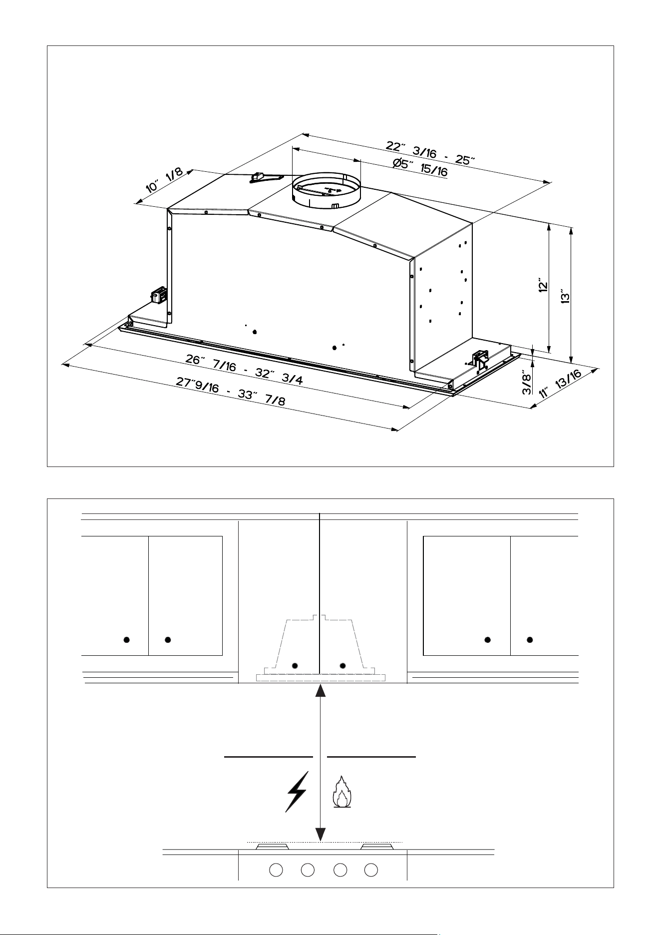
This rangehood requires at least 24" of clearance between the bottom of the rangehood
and the cooking surface or countertop. This hood has been approved by UL at this distance from
the cooktop.
This minimum clearance may be higher depending on local building codes. For gas cooktops and
combination ranges, a minimum of 30" is recommended and may be required.
Overhead cabinets on both sides of this unit must be a minimum of 18" above the cooking surface
or countertop. Consult the cooktop or range installation instructions given by the manufacturer
before making any cutouts.
MOBILE HOME INSTALLATION The installation of this rangehood must conform to the Manufactured
Home Construction and Safety Standards, Title 24 CFR, Part 3280 (formerly Federal Standard
for Mobile Home Construction and Safety, Title 24, HUD, Part 280). See Electrical Requirements.
• Venting system MUST terminate outside the home.
• DO NOT terminate the ductwork in an attic or other enclosed space.
• DO NOT use 4" laundry-type wall caps.
• Flexible-type ductwork is not recommended.
• DO NOTobstructtheowofcombustionandventilationair.
•Failuretofollowventingrequirementsmayresultina�re.
WARNING
VENTING REQUIREMENTS
Determine which venting method is best for your application. Ductwork can extend either through the
wall or the roof.
Thelengthoftheductworkandthenumberofelbowsshouldbekepttoaminimumtoprovideef�cient
performance. The size of the ductwork should be uniform. Do not install two elbows together. Use
ducttapetosealalljointsintheductworksystem.Usecaulkingtosealexteriorwallorooropening
around the cap.
Flexible ductwork is not recommended. Flexible ductwork creates back pressure and air turbulence
that greatly reduces performance.
Makesurethereisproperclearancewithinthewalloroorforexhaustductbeforemakingcutouts.
Do not cut a joist or stud unless absolutely necessary. If a joist or stud must be cut, then a supporting
frame must be constructed.
WARNING - To Reduce The Risk Of Fire, Use Only Metal Ductwork.
CAUTION-Toreduceriskof�reandtoproperlyexhaustair,besuretoductairoutside–Do
not vent exhaust air into spaces within walls or ceilings or into attics, crawl spaces, or garages.
Cold Weather installations
Anadditionalbackdraftdampershouldbeinstalledtominimizebackwardcoldairowandanon-
metallic thermal break should be installed to minimize conduction of outside temperatures as part of
the vent system. The damper should be on the cold air side of the thermal break. The break should
be as close as possible to where the vent system enters the heated portion of the house.
4
• Electrical ground is required on this rangehood.
• If cold water pipe is interrupted by plastic, nonmetallic gaskets or other materials, DO
NOT use for grounding.
• DO NOT ground to a gas pipe.
• DO NOT have a fuse in the neutral or grounding circuit. A fuse in the neutral or
grounding circuit could result in electrical shock.
•Checkwithaquali�edelectricianifyouareindoubtastowhethertherangehoodis
properly grounded.
•Failuretofollowelectricalrequirementsmayresultina�re.
WARNING
StateofCaliforniaProposition65Warning(USonly)
WARNING
This product contains chemicals known to the State of California to cause cancer and birth
defects or other reproductive harm.
For more information go to www.P65Warnings.ca.gov
ELECTRICAL REQUIREMENTS
A 120 volt, 60 Hz AC-only electrical supply is required on a separate 15 amp fused circuit.
A time-delay fuse or circuit breaker is recommended. The fuse must be sized per local
codesinaccordancewiththeelectricalratingofthisunitasspeci�edontheserial/rating
platelocatedinsidetheunitnearthe�eldwiringcompartment.

5
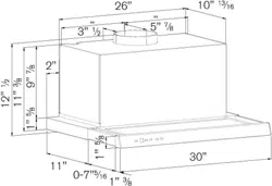
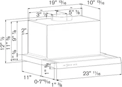
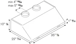
KIN30XV - KIN36XV
RANGEHOOD DIMENSIONS
Min. 24" Min. 30"
6
Available Accessories
Charcoal Filter kit sku #901531
Durablecharcoal�lterkitsku#901532
Remote Control Accessory sku #901575
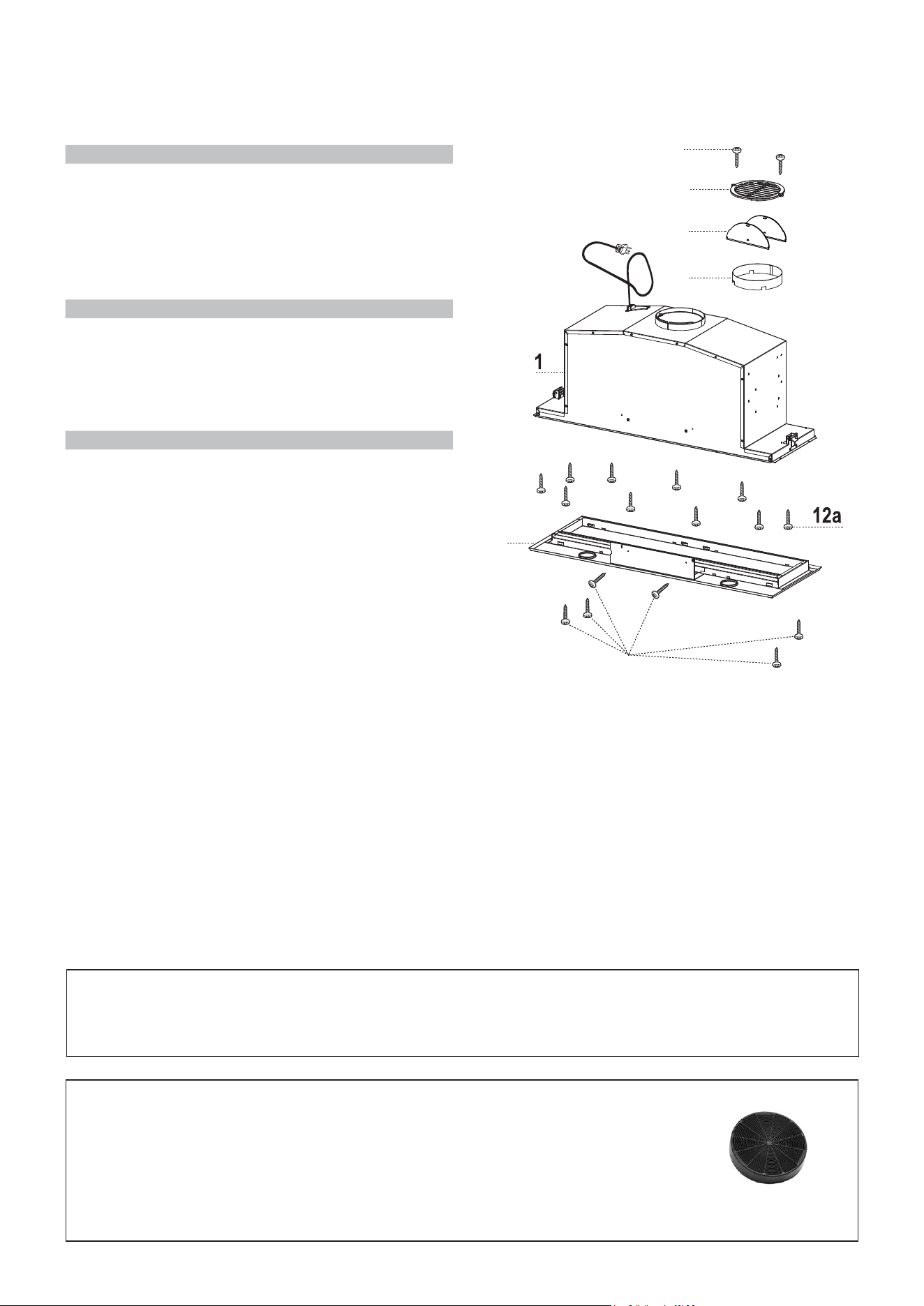
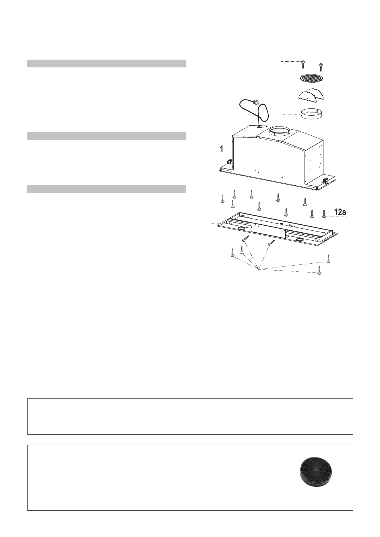
MAIN PARTSMAIN PARTS
Components
Ref. Qty. Product Components
1 1 Hood Body, complete with: Con-
trols, Light, Filters, Blower.
2 1 Frame
8 1 Recirculation Vent Grill
10a 2 Damperaps
10b 1 Metallic damper ring
Ref. Qty. Installation Components
12a 10 Screws (for hood installation)
12e 2 Screws 1/8"x3/8" (for Recircula
tion Vent Grill mounting)
12f 6 Screws 1/8"x5/16" torx (for
frame mounting)
Qty. Documentation
1 Instruction Manual
Parts needed
- 6" Round Metal ductwork.
8
10a
10b
12e
12f
2
7
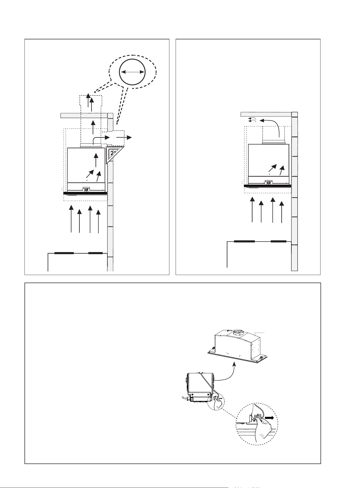
Choose your ducting method
Requires
purchase of
Activated
Charcoal
Accessory
Rear
Top
6"
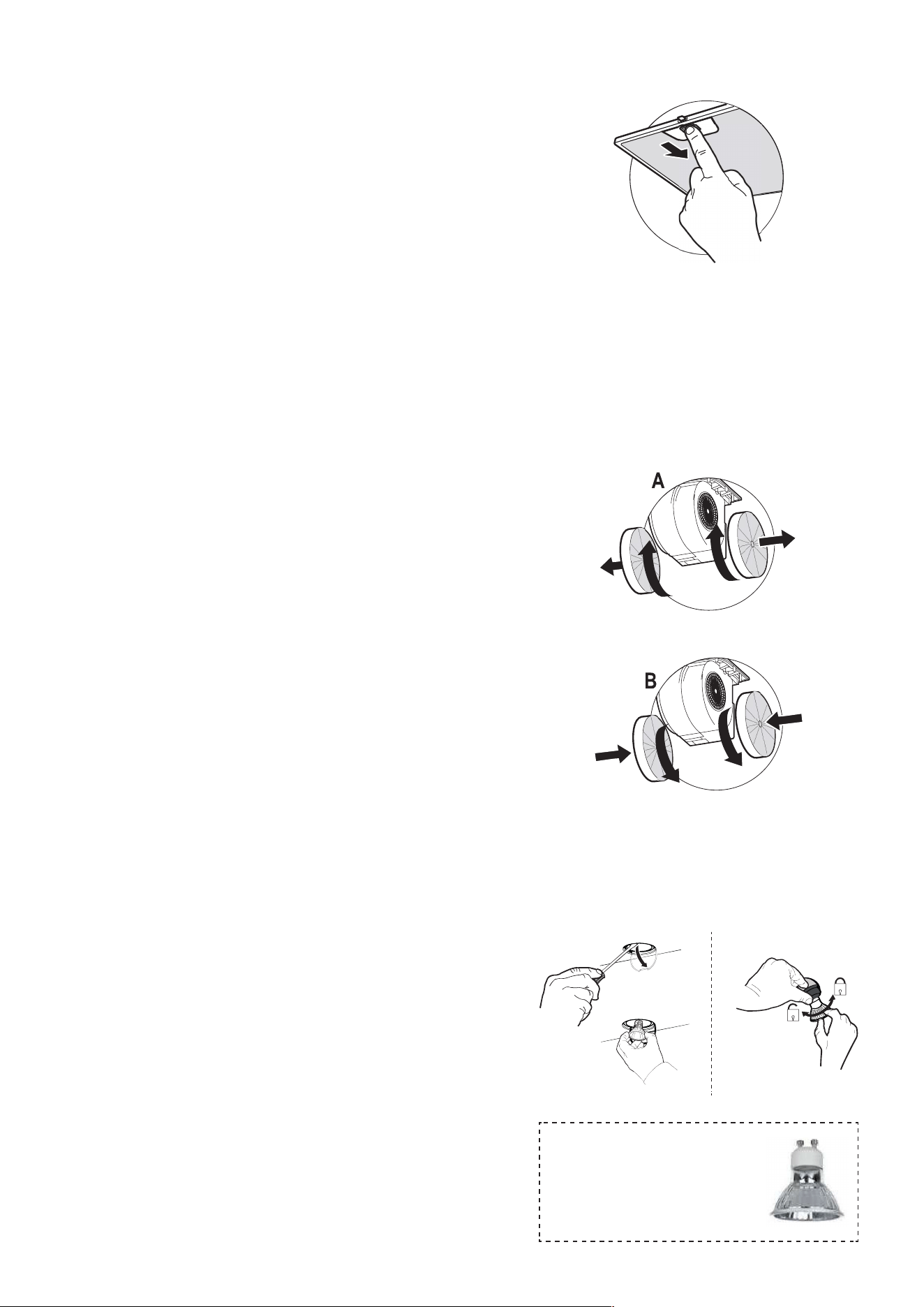
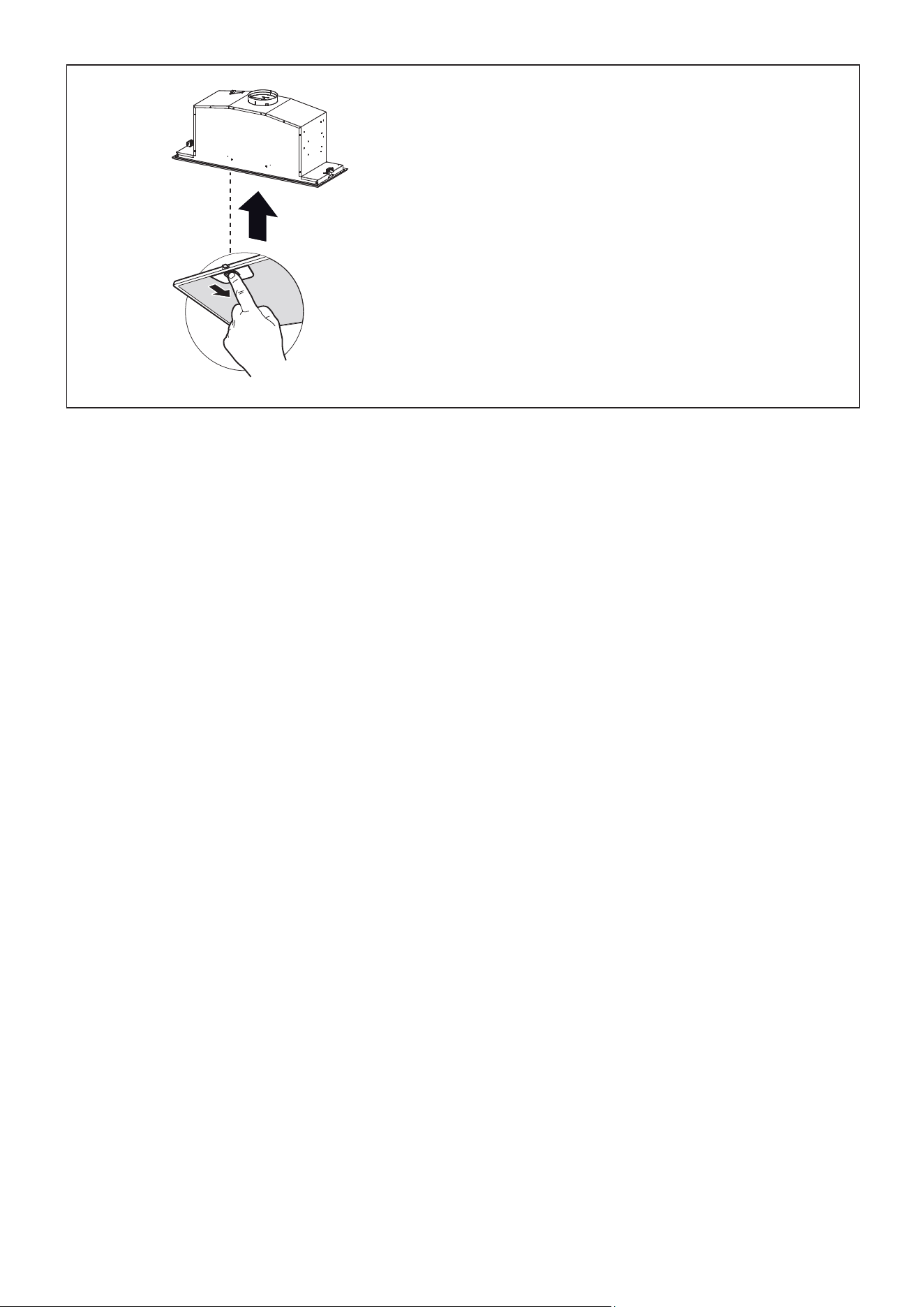
The Electrical Connection Cable
must be disconnected �rst before
installation;
Disconnect the Electrical Connector
asshowninthe�gure.Depressthe
two tabs on the side of the Electrical
Connector using your hand and a
smallatheadscrewdriverandpulloff.
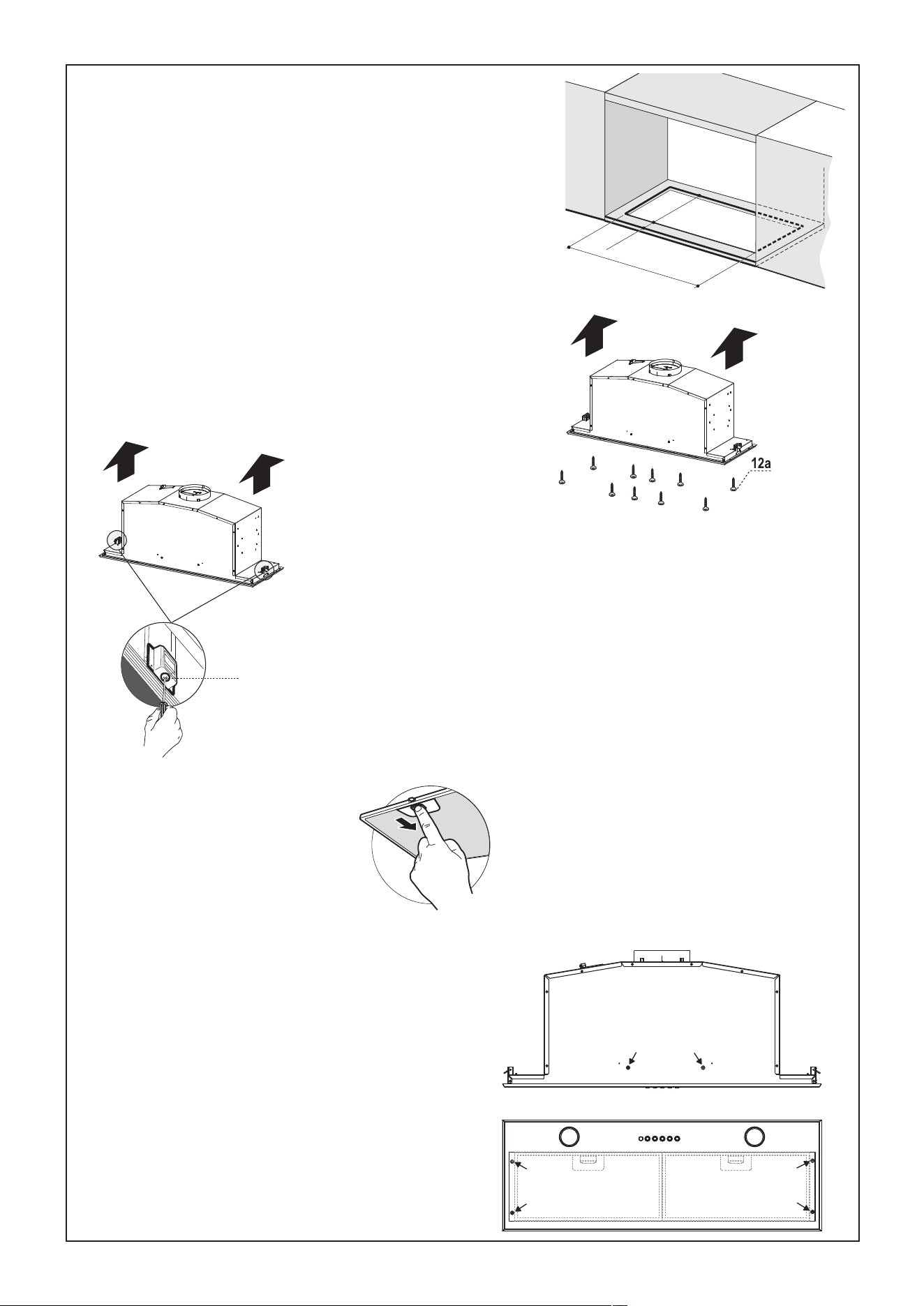
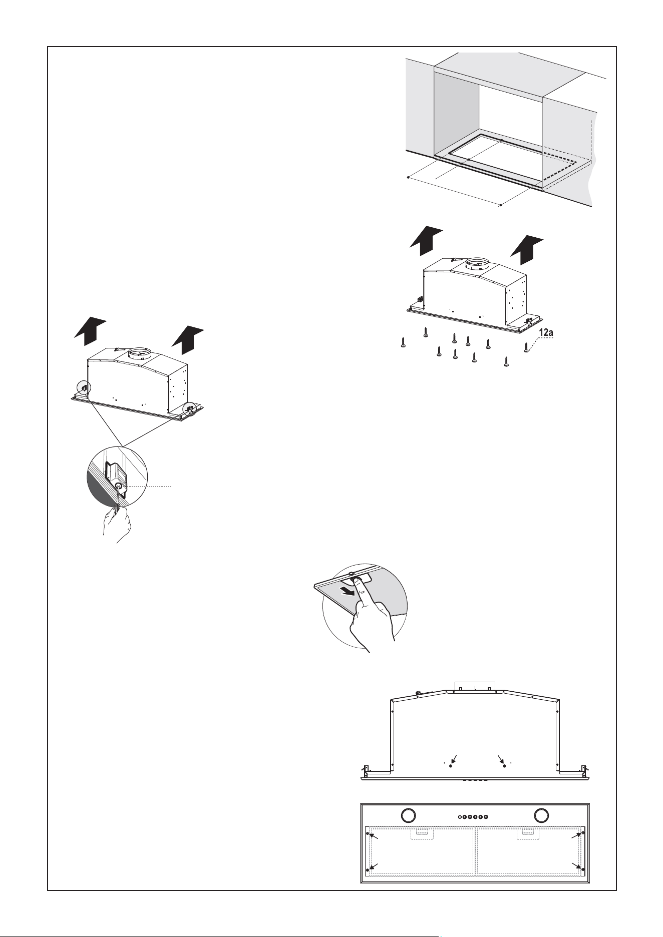
Install the rangehood
(FollowthesestepsbeforeattemptingtoinstalltheInsert)
1
Non Ducted - RecirculationDucted Venting Installation
1
8
Vf
The Hood can be installed directly on the underside of the wall
unit (Minimum 24" - 30" from the Cooking Surface).
Create an opening in the bottom of the wall unit, as shown.
Insert the hood until the side supports snap into place.
Fasten using the 10 screws 12aprovided.
Lock in position by tightening the screws Vf from underneath the hood.
Removegrease�ltersandsetaside.
Screw the Frame into place using the 6 screws
12f(1/8"x5/16" torx), reconnect the wires to the
Connector) removed previously. Replace the
metalgrease�lters.
10 1
/
8”
1/
2
”
2
6
7/
1
6
”
- 32
3/
4
”
9
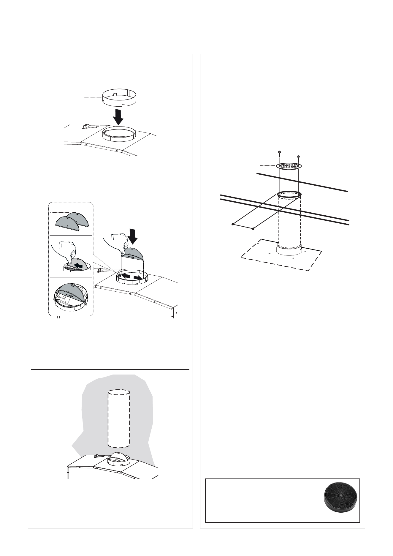
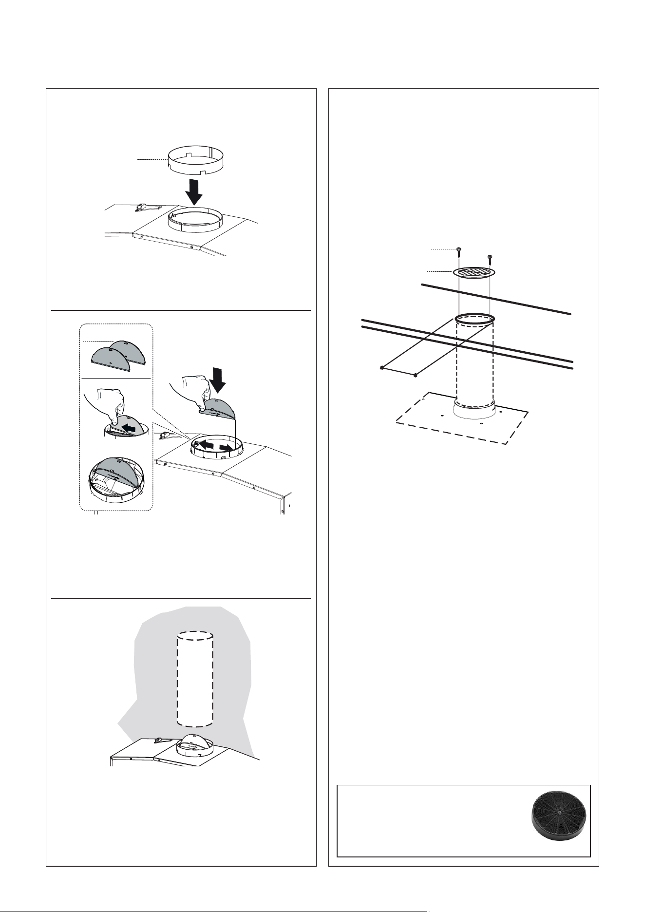
Choose your ducting method
Ducted Venting Installation
2
Non Ducted -
Recirculation Option
Install Roof or Wall Cap purchased sep-
arately. Connect the 6" metal ductwork
to the Roof or Wall Cap and then attach
ductwork. Seal with foil tape.
For Non-Ducted Recirculation venting route
the ductwork to a location above the hood
where the discharge is vented back into the
room.
Use the included Recirculation Vent Grill to
cover the opening. Secure the grill with the
2 screws provided in the Install Kit.
Fit a streight tube at least 15" in lenght from
the Hood air outlet to the wall unit.
Required Charcoal Filter kit sku
#901531
Durablecharcoal�lterkitsku
#901532
10a
8
10b
12e
Install metal damper ring (10b) included
with the Hood.
Installthedamperaps(10a)thatare
included with hood by snapping the tabs
into place inside the top of the hood
before connecting ductwork.

10
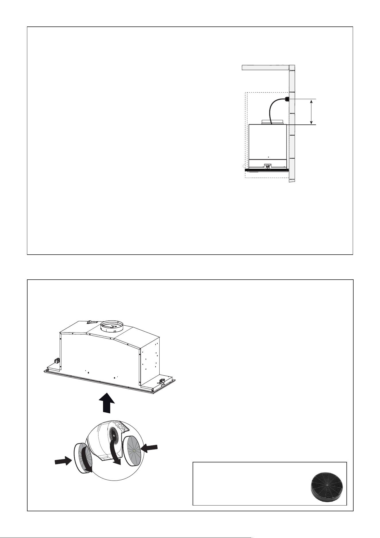
Max. 33
7/16
”
1
2
4
For Non-Ducted Recirculation Option
Attacheachcharcoal�ltertotheblack
grid on each side of the blower. Press the
charcoal�ltertightlytotheblackgridonthe
blowersideandrotatethe�lterclockwise
(towards the front of the insert hood) until
it locks into place. Turn counterclockwise
(towards the back of the insert hood) to
remove.
Required Charcoal Filter kit sku
#901531
Durablecharcoal�lterkitsku
#901532
GROUNDING INSTRUCTIONS This appliance must
be grounded. In the event of an electrical short circuit,
grounding reduces the risk of electric shock by providing
an escape wire for the electric current. This appliance
is equipped with a cord having a grounding wire with
a grounding plug. The plug must be plugged into an
outlet that is properly installed and grounded.
WARNING - Improper grounding can result in a risk
of electric shock.
Consultaquali�edelectricianifthegroundinginstruc-
tions are not completely understood, or if doubt exists
as to whether the appliance is properly grounded.
Do not use an extension cord. If the power supply cord
istooshort,haveaquali�edelectricianinstallanoutlet
near the appliance.
ELECTRICAL INSTALLATION
WITH CONNECTION CABLE
WARNING - "The supply cord shall be accessible for inspection after installation".
3

11
Replacethegrease�ltersremoved
previously.
5
12
USE AND CARE INFORMATION
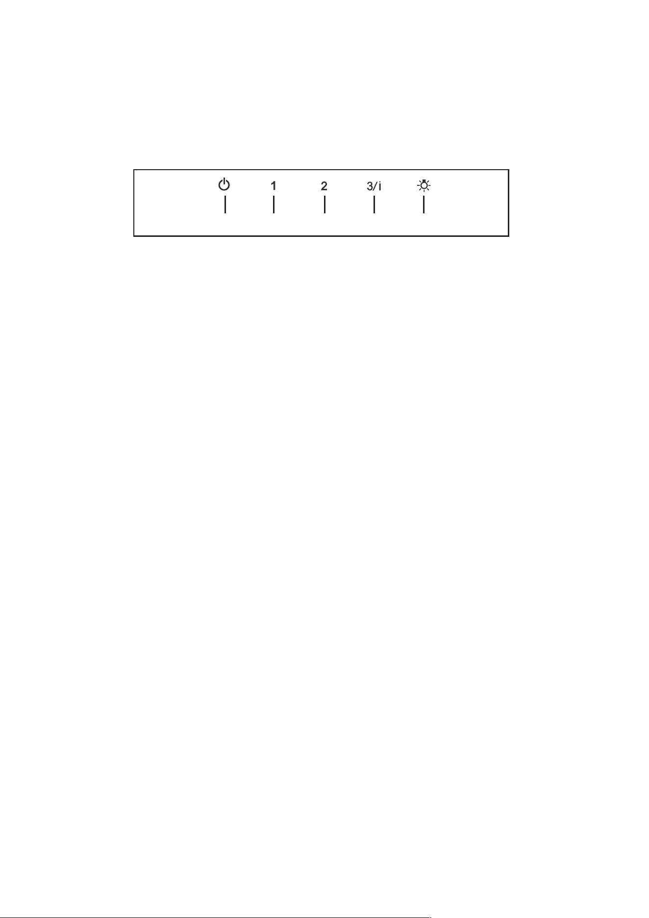
LT1 T2 T3 T4
For Best Results
Start the rangehood several minutes before cooking to develop proper airow.Allow the
rangehood to operate for several minutes after cooking is complete to clear all smoke and
odors from the kitchen.
T1. Fan off button:turn the blower Off. The fan can be operated by pressing any of the fan setting buttons.
Hold down this button for 2 seconds to activate Delay off function which will keep the fan on for 15
minutes and automatically shut off.
T2. Fan settings buttons: Low speed.
T3. Fan settings buttons: Medium speed.
T4. Fan settings buttons: High speed / Intensive speed.
Hold down the button for 2 seconds to activate the intensive speed, which is timed to run for 6
minutes. At the end of this time it will automatically return to the speed set before.Suitable to deal
with maximum levels of cooking fumes.
L. Light button: On/Off switch for the lights.
NOTE: If your product has had a CFM adjustment, refer to the CFM adjustment manual for the infor-
mation. Some motor speeds or functions may be reduced.
13
Cleaningmetalgrease�lters
Themetalgrease�lterscanbecleanedinhotdetergentsolution
orwashedinthedishwasher.Theyshouldbecleanedevery
2monthsuse,ormorefrequentlyifuseisparticularlyheavy.
• Removethe�lter,pushingthelevertowardsthebackofthe
unit and at the same time pulling downward.
• Washthe�lterwithoutbendingit,leaveittodrythoroughly
beforereplacing(ifthesurfaceofthe�lterchangescolor
overtime,thiswillhaveabsolutelynoeffectonitsef�ciency).
• Replace, taking care to ensure that the handle faces forward.
• Cleaning in dishwasher may dull the �nish of the metal
grease�lter.
• Nowatercanbepresentin�ltersbeforeinstallingbackinhood.
Replacing Activated Charcoal Filter
TheActivatedCharcoalFiltersarenotwashableandcannot
be regenerated, and should be replaced approximately
every4monthsofoperation,ormorefrequentlywithheavy
usage.
• RemovetheFilter,pushingittowardsthebackoftheunit
and at the same time pulling downward.
• RemovethesaturatedActivatedCharcoalFilters,asindi-
cated (A).
• Fit the new Filters, as indicated (B).
• Replace, taking care to ensure that the handle faces forwards.
Caution: "When used in recirculation mode, to Reduce
theRiskofFireandShockuseonlyconversionkitModel
CharcoalFilterkitsku#901531;Durablecharcoal�lterkit
sku #901532".
Please contact the retailer that sold you the product to
purchasecarbon�ltersabove.
Lighting unit
• Replace the lamp with a new one of the same type, making
sure that you insert the two pins properly into the housings
on the lamp holder.
Gu10 self-ballasted
led lamps – listed in
accordance with ul 1993/
nmx-j-578/1-ance/csa
c22.2 No. 1993

14
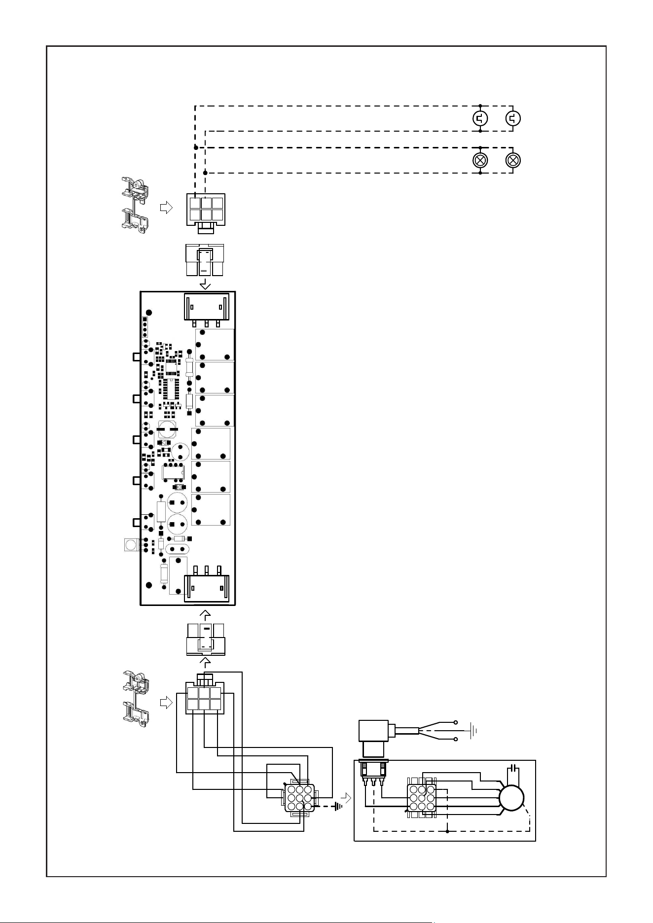
Wiring Diagram

15
Pleasekindlyregisteronourwebsitewww.bertazzoni.comtovalidateyournewproductwarranty
andhelpustoassistyoubetterincaseofany inconvenience.
TWOYEARLIMITEDWARRANTY
ThewarrantiesprovidedbyBertazzoniSpain thisstatementapply exclusivelytoBertazzoniappliancesand
accessoriessoldasnewproductstotheoriginalownerbyaBertazzoniauthorizeddistributor,retailer,dealeror
servicecenterandinstalledintheUnitedStatesandCanada.Thewarrantiesprovidedinthisstatementare
nottransferableandhavevalidityfromthedateofinstallation.
COVERAGEINFORMATION
BertazzoniSpAwillrepairorreplaceanycomponentpartwhichfailsorprovesdefectiveduetomaterialsand/or
workmanshipwithin2yearsfromthedateofinstallationandunderconditionsofnormalresidentialuse.Repair
orreplacement willbefreeofcharge,includinglabor atstandardratesandshippingexpenses. Repairservice
must beperformedbyaBertazzoniAuthorizedService
Centerduringnormalworkinghours.
COSMETICWARRANTY
Bertazzoniwillcoverpartsshowingcosmeticdefectsinmaterialandworkmanshipforaperiodofthirty(30)days
fromdateofinstallationoftheunit.Thiscoveragewillincludescratches,stains,surfaceimperfectionson
stainlesssteel,paint andporcelain, withtheexclusionofslight differencesincolorduetomaterialsand
painting/enamellingtechnologies.
Exclusionsarelaborcosts,Bstockitems,out
‐
of
‐
boxappliancesanddisplayunits.
HOWTOOBTAINSERVICE
ToobtainservicepleasecontactBertazzoniCustomerServiceatthenumbersbelowandmakesureto
havemodelnumber,serialnumber,anddateofpurchaseready.Thisinformationwillberequestedbyour
teamandiscrucialtospeedingupresolution.
UNITEDSTATEShttps://us.bertazzoni.com/more/support
Phone:866-905-0010
CANADAhttps://ca.bertazzoni.com/more/support
Phone:800-361-0799
Saveproofoforiginalpurchaseoroforiginalinstallationtoestablishwarrantyperiod.Copyoftheproductserial
tagisaffixedtothebackcoveroftheinstruction manual.
WHATISNOTCOVERED
1.
Theproductusedinanycommercial/businessapplication
2.
RepairserviceprovidedbyotherthanaBertazzoniauthorizedserviceagent.
3.
Damageorrepairservicetocorrectserviceprovidedbyanunauthorizedagencyortheuseof
unauthorizedparts.
4.
Installationnotinaccordancewithlocalelectricalcodesorplumbingcodes.
5.
Defectsordamageduetoimproperstorageoftheproduct.
6.Defectsordamageormissingpartsonproductssoldoutoftheoriginalfactorypackagingorfrom
displays.
7. Servicecallsorrepairstocorrecttheinstallationoftheproductand/orrelatedaccessories.
8. Servicecallstoconnect,convertorotherwiserepairtheelectricalwiring/gasline/waterlineto
properlyusetheproduct.
9. ServicecallstoprovideinstructionsontheuseofaBertazzoniproduct.
10. Repairserviceduetoproductusageinmannerotherthanwhatisnormalandcustomaryforhomeuse.
11. Replacementofwearandtearparts
12.Replacementofglasses andlight bulbs if they areclaimed tohavefailed laterthan 30days
after installationandinnocaselaterthan4monthsafterdateofpurchase
13. Defectsand damages arisingfrom accident, alteration, misuse, abuse,improperinstallation.
14. Defectsanddamagesarisingfromtransportationoftheproducttothehomeoftheowner.
15.DefectsanddamagearisingfromexternalforcesbeyondthecontrolofBertazzoniSpAsuch
asfire,flood,earthquakesandotheractsofGod.
Incasetheproductwillbeinstalledinaremotearea,wherecertifiedtrainedtechniciansarenot
reasonably available, the customer will be responsible for the transportation costs for the
deliveryoftheproducttothenearestauthorizedservicecenterorforthedisplacementcostsofa
certifiedtrainedtechnician.
Bertazzonidoesnotassumeanyresponsibilityforincidentalorconsequentialdamages.
Somestatesdonotallowtheexclusionorlimitationofincidentalorconsequentialdamages,sothe
abovelimitationorexclusionmaynotapplytoyou.Thiswarrantygivesyouspecificlegalrightsandyoumayalso
haveotherrightswhichmayvaryfromstatetostateorprovincetoprovince.

16
VEUILLEZ LIRE ET CONSERVER LA PRÉSENTE NOTICE AVANT DE
COMMENCER L'INSTALLATION DE LA HOTTE DE CUISINE
AVERTISSEMENT:POURRÉDUIRELERISQUED'UNFEUDEGRAISSESURLATABLEDECUISSON:
a) Ne laissez jamais sans surveillance les éléments de la surface de cuisson à température élevée. Les
bouillonnements excessifs peuvent provoquer de la fumée et les débordements de graisse peuvent
s'enflammer. L'huile doit être chauffée lentement, à une température basse ou moyenne.
b) Assurez-vous de toujours mettre en marche le ventilateur de la hotte lorsque vous cuisinez à tem-
pératureélevéeoupréparezunmetsflambé(p.ex.crêpesSuzette,cerisesjubilé,bœufflambé).
c) Nettoyez régulièrement les ventilateurs d'aspiration. Assurez-vous de ne pas laisser de la graisse
s'accumuler sur le ventilateur ou le filtre.
d) Utilisez toujours des poêles et casseroles de la taille appropriée. Utilisez toujours des ustensiles de
cuisine de la taille adaptée à celle de l'élément chauffant.
AVERTISSEMENT:-POURPRÉVENIRLESBLESSURESENCASDEFEUDEGRAISSESURLATABLE
DECUISSON,SUIVEZLESRECOMMANDATIONSSUIVANTES*:
a) ÉTOUFFEZ LES FLAMMES à l'aide d'un couvercle hermétique, d'une plaque à biscuits ou d'un plateau
métallique, puis éteignez le brûleur. FAITES ATTENTION AUX BRÛLURES. Si le feu ne s'éteint pas
immédiatement, QUITTEZ LES LIEUX ET APPELEZ LES POMPIERS.
b) NE PRENEZ JAMAIS UNE CASSEROLE EN FLAMME - Vous pourriez vous brûler.
c) N'UTILISEZ JAMAIS DE L'EAU, ni un linge à vaisselle ou un torchon mouillé, pour éteindre le feu.
Cela pourrait provoquer une violente explosion de vapeur.
d)UtilisezunextincteurUNIQUEMENTsi:
1. Vous êtes certain qu'il s'agit d'un extincteur de classe ABC et que vous connaissez bien son
mode d'emploi.
2. Le feu est de faible intensité et se limite à l'endroit où il a démarré.
3. Les pompiers ont déjà été appelés.
4. Une voie de sortie se trouve derrière vous pendant que vous éteignez les flammes.
*D'aprèsleguide«KitchenFiresafetyTips»publiéparlaNFPAauxÉtats-Unis
AVERTISSEMENT - POUR RÉDUIRE LE RISQUE D'INCENDIE OU DE CHOC ÉLECTRIQUE, n'utilisez
jamais ce ventilateur en association avec un dispositif de réglage de vitesse à semi-conducteurs.
AVERTISSEMENT - POUR RÉDUIRE LES RISQUES D'INCENDIE, DE CHOC ÉLECTRIQUE OU DE
BLESSURECORPORELLE,RESPECTEZLESINSTRUCTIONSSUIVANTES:
1. Utilisez cet appareil uniquement de la façon prévue par le fabricant. Pour toute question, com-
muniquez avec le fabricant.
2. Avant de procéder à l'entretien ou au nettoyage de l'appareil, coupez l'alimentation au niveau du
panneau électrique et verrouillez-le pour vous assurer que l'électricité n'est pas rétablie accidentel-
lement. S'il n'est pas possible de verrouiller le dispositif d'interruption de l'alimentation, affichez de
façon ferme et bien visible un avis de danger, par exemple à l'aide d'une étiquette sur le panneau.
ATTENTION:Destinéàunusagedeventilationgénéraleuniquement.N'utilisezpascedispositifpour
l'aspiration de vapeurs ou de matériaux dangereux ou explosifs.
AVERTISSEMENT - POUR RÉDUIRE LES RISQUES D'INCENDIE, DE CHOC ÉLECTRIQUE OU DE
BLESSURECORPORELLE,RESPECTEZLESINSTRUCTIONSSUIVANTES:
1. L'installation et le branchement électrique doivent être réalisés par un technicien qualifié et con-
formément à tous les codes et normes en vigueur, incluant ceux concernant la construction à
l'épreuve du feu.
2. Afin de garantir une combustion et une évacuation adéquates des gaz par les conduites de la che-
minée des appareils à combustion, une bonne aération est nécessaire pour éviter le refoulement.
Respectez les lignes directrices fournies par le fabricant du matériel chauffant, ainsi que les normes
desécuritécommecellespubliéesparlaNationalFireProtectionAssociation(NFPA)etlaAmerican
SocietyforHeating,RefrigerationandAirConditioningEngineers(ASHRAE)auxÉtats-Unis,ainsi
que les codes en vigueur dans votre région.
3. Lorsque vous faites une ouverture ou percez dans un mur ou le plafond, veillez à ne pas endom-
mager les fils électriques ou d'autres dispositifs cachés.
17
4. Les ventilateurs canalisés doivent toujours être raccordés à l'extérieur.
TOUTEOUVERTUREDANSLEMUROULEPLANCHERÀPROXIMITÉDELAHOTTEDOIT
ÊTRESCELLÉE.
Un espace libre d'au moins 24" est requis entre le bas de la hotte et la surface de cuisson ou le comptoir.
Cettehotteaétéhomologuéeparl'ULàcettedistancedelasurfacedecuisson.
L’espacelibreminimalrequispeut-êtreplusgrand,selonlaréglementationenmatièredeconstructiondevotre
région.Pourlescuisinièresàgazetlescuisinièrescombinées,unespaceminimalde30"estrecommandé
etpourraitêtreexigé.
Lesarmoiressuspenduesdechaquecôtédel'appareildoiventsetrouveràaumoins18"delasurfacede
cuisson ou du comptoir. Consultez la notice d'installation de la surface de cuisson ou de la cuisinière fournie
par le fabricant avant de pratiquer des ouvertures.
INSTALLATIONDANSUNEMAISONMOBILEL'installationdecettehottedoitêtreconformeàlaPartie
3280delanormeManufacturedHomeConstructionandSafetyStandards,Title24CFR(précédemment
la partie 280 de la norme Federal Standard for Mobile Home Construction and Safety, Title 24, HUD).
Consultezla�chetechniqueélectrique.
•LesystèmedeventilationDOITdéboucheràl'extérieur.
• NE FAITES PASdéboucherlesconduitsdansungrenierouunautreendroitfermé.
• N'UTILISEZ PASunclapetdesécheusemuralde4po.
•Iln'estpasrecommandéd'utiliserdesconduitsexibles.
• N'ENTRAVEZ PASleuxdel'airdecombustionetdeventilation.
• Le non-respect des exigences en matière de ventilation pourrait entraîner un incendie.
AVERTISSEMENT
CRITÈRES DE VENTILATION
Déterminezquelleméthodedeventilationestmieuxadaptéeàvotreapplication.Lesconduitspeuventpasser
par le mur ou le toit.
Pourgarantirunemeilleureefficacité,lalongueurdesconduitsetlenombredecoudesdoiventêtreleplus
limitésquepossible.Lediamètredesconduitsdevraitêtreuniforme.N'installezpasdeuxcoudesensemble.
Utilisez un ruban pour canalisations afin de sceller tous les joints du système de conduits. Utilisez un calfeutrage
pourscellerlesouverturesdanslemurextérieurouleplancher,autourduclapet.
Il n'est pas recommandé d'utiliser des conduits flexibles. Les conduits flexibles provoquent une contre-pression
et de la turbulence qui diminuent grandement l'efficacité de l'appareil.
Assurez-vousquel'espacelibredanslemurouleplancherestsuffisantpourleconduitd'évacuationavantde
pratiquerlesouvertures.Necoupezjamaisunepoutreouunchevron,saufsic'estabsolumentnécessaire.
S'ils'avèrenécessairedecouperunepoutreouunchevron,laconstructiond'unrenforcementestrequise.
AVERTISSEMENT - Pour réduire le risque d'incendie, utilisez uniquement des conduits métalliques.
ATTENTION - Pour réduire le risque d'incendie et pour évacuer adéquatement l'air, assurez-vous
deraccorderlesconduitsàl'extérieur–Nediffusezpasl'aird'évacuationdansdesespacesà
l'intérieur des murs ou du plafond, ou encore à l'intérieur d'un grenier, d'une galerie technique ou
d'un garage.
Installation dans les climats froids
Lesystèmedeventilationdoitprévoirunregistreantirefoulementsupplémentairepourréduireleuxd'air
froidinverse,ainsiqu'unebarrièrethermiquenonmétalliquepourréduirelaconductiondestempératures
extérieures.Leregistredoitêtreinstalléducôtéairfroidparrapportàlabarrièrethermique.Labarrière
thermiquedoitêtrepositionnéeleplusprèsquepossibledel'endroitoùlesystèmedeventilationpénètre
danslapartiechaufféedelamaison.

18
•Unemiseàlaterreélectriqueestrequisepourcettehotte.
•N'UTILISEZPASuntuyaud'eaufroidepourlamiseàlaterresicelui-ciestbranchépardes
jointsenplastique,pardesrondellesnonmétalliquesoud'autresmatériaux.
•N'UTILISEZPASuneconduitedegazpourlamiseàlaterre.
•N'INSTALLEZPASunfusiblesurlecircuitneutreoulecircuitdemiseàlaterre.Laprésence
d'unfusibledanslecircuitneutreoudemiseàlaterrepeutentraînerunchocélectrique.
•Consultezunélectricienquali�ésivousn'êtespascertaindelamiseàlaterredelahotte.
•Lenon-respectdesexigencesdela�chetechniqueélectriquepourraitentraînerunincendie.
AVERTISSEMENT
Avertissementdelaproposition65del'ÉtatdeCalifornie(USseulement)
ATTENTION
Ce produit contient des produitschimiquesconnusdel'ÉtatdeCaliforniepourcauserle
canceretdesmalformationscongénitalesoud'autresproblèmesdereproduction.
Pour plus d'informations, visitez www.P65Warnings.ca.gov
FICHE TECHNIQUE ÉLECTRIQUE
Unealimentationdecourantalternatifde120voltsà60Hzestrequisesuruncircuità
fusibledistinctde15ampères.Ilestrecommandéd'installerunfusibletemporiséou
undisjoncteur.Lefusibledoitêtrecalibréconformémentauxcodesenvigueurpourles
caractéristiquesnominalesélectriquesdel'appareil,indiquéessurlaplaquesignalétique
situéeàl'intérieurdel'appareil,àproximitéducompartimentdescâblagesexternes.
19
KIN30XV - KIN36XV
DIMENSIONS DE LA HOTTE
Min. 24" Min. 30"
20
Accessoires disponibles
Kit�ltreàcharbonsku#901531
Kit�ltreàcharbondurablesku#901532
Accessoirecommandeàdistancesku#901575
PIÈCES PRINCIPALES
Composants
Réf. Qté Composants du produit
1 1 Bâtidelahotte,avec:
Commandes, éclairages,
�ltres,ventilateur.
2 1 Bâti
8 1 Grilled'éventderecirculation
10a 2 Clapet
10b 1 Anneau métallique du clapet
Réf. Qté Composants d'installation
12a 10 Vis (pour installation de la hotte)
12e 2 Vis 1/8"x3/8" (pour montage de
lagrilled'éventderecirculation)
12f 6 Vis 1/8"x5/16" torx (pour mon
tage du bâti)
Qté Documentation
1 Mode d'emploi
Pièces requises
- Conduit métallique 6" circulaire.
8
10a
10b
12e
12f
2

21
Choisissez la méthode de canalisation
Exige
l'achat de
l'accessoireà
charbon actif
Arrière
Haut
6"
Le câble de connexion électrique doit
êtredébranchéavantl'installation;
Débranchez le connecteur électrique
commeindiquésurla�gure.Appuyez
sur les deux languettes situées sur le
côtéduconnecteurélectriqueavec
votremainetunpetittournevisàtête
plate et retirez-les.
Installation la hotte
(Suivezcesétapesavantdetenterd'installerl’encastrable)
1
Sans canalisation - RecirculationInstallation avec ventilation canalisée
1
22
Vf
La hotte peut être installée directement sur la face en bas de
l'unitémurale(àunedistanceminimalede24à30poucesde
la surface de cuisson).
Créezuneouverturedanslebasdel'unitémurale,commeillustré.
Insérezlahottejusqu'àcequelessupportslatérauxs'enclenchentenplace.
Fixezàl'aidedes10vis12a fournies.
VerrouillezenpositionenserrantlesvisVf par le dessous de la hotte.
Retirezles�ltresàgraisseetmettez-lesàpart.
Vissezlecadreàl'aidedes6vis12f (1/8 "x5/16"
torx),rebranchezles�lsauconnecteur)précédem-
mentretiré.Remettezenplaceles�ltresàgraisse
métalliques.
10 1
/
8”
1/
2
”
2
6
7/
1
6
”
- 32
3/
4
”
23
Choisissez la méthode de canalisation
Installation de la ventilation
par conduits
2
Option de recirculation sans conduit
Installez le capuchon de toit ou de mur
acheté séparément. Raccordez la gaine
métallique de 6 po au capuchon de toit
oudemur,puis�xezlagaine.Scellez
avec du ruban adhésif.
Pourcetteoption,acheminezleconduità
un endroit situé au-dessus de la hotte où
l'évacuation est renvoyée dans la pièce.
Utilisez la grille d'évent de recirculation
incluse pour couvrir l'ouverture. Fixez la
grille avec les 2 vis fournies dans le kit
d'installation.
Installez un tube droit d'au moins 15" de
longueur entre la sortie d'air de la hotte et
l'unité murale.
Kitde�ltreàcharbondebois
requis sku #901531
Kit�ltreàcharbondurablesku
#901532
10a
8
10b
12e
Installez l'anneau métallique du clapet
(10b) fourni avec la hotte.
Installez les volets de clapet (10a) inclus
avec la hotte en mettant les languettes
enplaceàl'intérieurduhautdelahotte
avant de raccorder les conduits.
24
Max. 33
7/16
”
1
2
4
Pour option non canalisée avec recirculation d'air
Fixezles�ltresàcharbonàlagrillenoire
de chaque côté du ventilateur. Pressez
fermementle�ltreàcharboncontrelagrille
noire de chaque côté du ventilateur et faites
tournerle�ltredanslesensdesaiguilles
d'une montre (vers l'avant de la hotte
encastrable)jusqu'àcequ'ilsoitverrouilléen
place. Faites tourner dans le sens contraire
des aiguilles d'une montre (vers l'arrière de
la hotte encastrable) pour l'enlever.
Kitde�ltreàcharbondebois
requis sku #901531
Kit�ltreàcharbondurablesku
#901532
3
INSTRUCTIONS DE MISE À LA TERRE Cet appareil
doitêtremisàlaterre.Encasdecourt-circuitélectrique,
lamiseàlaterreréduitlerisquedechocélectriquegrâce
àun�ldefuitepourlecourantélectrique.Cetappareilest
équipéd'uncordoncomportantun�ldemiseàlaterreet
une�chedemiseàlaterre.Veuillezbranchercette�che
doit être branchée dans une prise de courant correctement
installéeetmiseàlaterre.
AVERTISSEMENT-Unemiseàlaterreincorrectepeut
entraîner un risque de choc électrique.
Consultezunélectricienquali�ésivousnecomprenezpas
parfaitementlesinstructionsdemiseàlaterreousivous
avezdesdoutesquantàlamiseàlaterredel'appareil.
N'utilisez pas de rallonge électrique. Si le câble
d'alimentationesttropcourt,demandezàunélectricien
quali�éd'installerunepriseàproximitédel'appareil.
INSTALLATION ÉLECTRIQUE
AVEC CÂBLE DE CONNEXION
AVERTISSEMENT - « Le cordon d'alimentation doit être accessible pour inspection après
l'installation ».
25
Replacezles�ltresàgraisseenlevés
précédemment.
5

26
LT1 T2 T3 T4
INFORMATIONS POUR L'UTILISATION ET L'ENTRETIEN
Pour de meilleurs résultats
Activezlahottequelquesminutesavantdecommenceràcuisinerpourcréerunuxd'air
adéquat. Laissez la hotte fonctionner quelques minutes après avoir �ni de cuisiner pour
absorber toute la fumée et les odeurs de la cuisine.
T1. Bouton arrêt du ventilateur : éteint le ventilateur. Le ventilateur peut être allumé en ap-
puyant sur l'un ou l'autre des boutons de réglage.
Tenez ce bouton enfoncé pendant 2 secondes pour activer la fonction de désactivation
retardée, qui éteindra automatiquement le ventilateur après 15 minutes de marche.
T2. Boutons de réglage du ventilateur : vitesse réduite.
T3. Boutons de réglage du ventilateur : vitesse moyenne.
T4. Boutons de réglage du ventilateur : vitesse élevée / vitesse intensive.
Tenez le bouton enfoncé pendant environ 2 secondes pour activer la vitesse intensive,
pouruneduréede6minutes.Aprèscedélai,lavitesseretourneraautomatiquementà
la vitesse sélectionnée précédemment. Utile pour contrer les émanations maximales de
cuisson.
L. Bouton pour l'éclairage: commutateur marche/arrêt pour l'éclairage.
REMARQUE: Si votre produit a subi un réglage CFM, reportez-vous au manuel de réglage CFM
pour plus d'informations. Certaines vitesses de moteur des fonctions peuvent être réduites.

27
Nettoyagedes�ltresàgraissemétalliques
Les�ltresàgraissemétalliquespeuventêtrelavésdansune
solutiond'eauchaudesavonneuseoudansle lave-vaisselle.
Ilsdevraientêtrenettoyéstousles2moisd'utilisation,ouplus
fréquemmentencasd'utilisationparticulièrementintensive.
• Retirez le �ltre, en poussant simultanément le levier vers
l'arrièredel'appareiletenletirantverslebas.
• Lavezle�ltresansleplier.Laissez-leséchercomplètement
avantdeleréinstaller(unchangementdelacouleuràlasurface
du�ltreau�ldutempsn'aaucunimpactsursonef�cacité).
• Remettez-leenplace,envousassurantquelapoignéese
trouveversl'avant.
• Le lave-vaisselle pourrait ternir le �ni du �ltre à graisse
métallique.
• Aucuneeaunepeutêtreprésentedansles�ltresavantla
réinstallation dans la hotte.
Remplacementdu�ltreàcharbonactif
Les�ltresàcharbonactifnesontpaslavablesetnepeuvent
être régénérés. Ilsdoiventêtreremplacésenviron tous les4
moisd'utilisation,ouplussouventencasd'utilisationintensive.
• Retirezle�ltre,enlepoussantsimultanémentversl'arrière
del'appareiletenletirantverslebas.
• Retirezles�ltresàcharbonactifsaturéscommeindiqué(A).
• Posezlesnouveaux�ltres,commeindiqué(B).
• Remettez-leenplace,envousassurantquelapoignéese
trouveversl'avant.
Attention : « Lorsqu'il est utilisé en mode recirculation, pour
réduire le risque d'incendie et de choc, utilisez uniquement le
kitdeconversionModèlede�ltreàcharbonsku#901531;Kit
de�ltreàcharbondurablesku#901532».
Veuillezcontacterledétaillantquivousavenduleproduitpour
acheterles�ltresàcharbonci-dessus.
Système d'éclairage
• Remplacezl'ampouleavecunenouvelledumêmetype,en
vousassurantd'insérercorrectementlesdeuxconnecteurs
dans leur logement sur le socle.
LampesDELàballast
intégré de type Gu10 –
répondantàlanormeUL
1993/nmx-j-578/1-ance/
csa c22.2 No 1993
28
Schéma de câblage

29
Nous
Vous
prions
de
bien
vouloir
vousenregistrer
sur
notre
site
web
www.bertazzoni.com
pour
valider
votre
garantie
du
nouveau produit et nous aider à Vous aider dans le cas de dommages.
GARANTIE LIMITEE DE DEUX ANS
LesgarantiesoffertesparBertazzoniSpadanscettedéclarations’appliquentexclusivementauxappareils et composants
Bertazzonivenduscommeneufsaupropriétaire originalparundistributeur, détaillant, concessionnaire
oucentredeserviceautoriséset installésaux Etats-Uniset Canada.Lesgarantiesfourniesdans cettedéclarationne peuvent
pas être transférées et sont valables à partir de la date d’installation.
INFORMATIONS SUR LA COUVERTURE
Bertazzoni SpAprocéderaàlaréparationouremplacera toutcomposantdéfectueuxàcausedesmatériauxet/ou fabrication
pendant2ansàcompterdeladated’installationetdanslesconditionsnormalesd’utilisationdansle cadrefamilial. La
réparationouleremplacementseronteffectuésàtitregratuitet inclurontlesfraisdemain d’oeuvreautarifnormaletles frais
d’expédition. Les réparations doiventêtreeffectuéespar un Centrede Service Bertazzoni Autorisépendantlesheures de travail
normales. Lesdéfauts doiventêtre signalésdans les 30 jours qui suiventl’installation. Cettegarantiene couvre pas
l’utilisation du produit dans le cadre commercial.
GARANTIE ESTHETIQUE
BertazzoniSpAcouvrelespiècesprésentant desdéfautscosmétiquesdematériauxet de fabricationpourune période
detrente(30)joursàcompterdeladated'installationdel'unité.Cettecouvertureincluralesrayures, lestaches,les imperfections
de surface sur l'acier inoxydable, de la peinture et de la porcelaine, à l'exclusion de légères différences de couleur dûes à des
matériaux et des technologies de peinture / émaillage.
Les coûts de main-d'oeuvre, B stock, appareils out-of-box et les unités d'affichage sont exclus COMMENT
OBTENIR LE SERVICE CLIENT
Pour obtenir le service de garantie, veuillez contacter Bertazzoni Customer Service aux numéros indiqués ci-dessous et
fournir le numéro du modèle, le numéro de série et la date d’achat.
Cette information sera demandée par notre équipe et serà très important pour accélérer la résolution du problème.
UNITED STATES
https://us.bertazzoni.com/more/support
Phone: 866-905-0010
CANADA
https://ca.bertazzoni.com/more/support
Phone : 800-361-0799
Il faut conserver la preuve d’achat ou l’origine de l’installation afin d’établir la période de garantie. Une copie du numéro
de série sera collée derrière le manuel d’emploi.
CE QUI NE SERA PAS PRIS EN CHARGE
1.
Le produit utilisé dans toute application commerciale/commerciale.
2.
Service de réparation fourni par un agent de service autorisé autre que Bertazzoni.
3.
N’importequeldommageouservicederéparationnécessairepourcorrigerunserviceeffectuépar un agence non autorisé
et/ou par suite d'utilisation de pièces non autorisés.
4.
Installation non conforme aux codes électriques locaux ou aux codes de plomberie.
5.
Les défauts ou dommages dûs à une mauvaise conservation du produit.
6.
Lesdéfautsoudommagesetlespiècesoubliéessurlesproduitsvendusaudehorsdel'emballaged'origineou d’affichage.
7.
Les appels de service ou des réparations pour corriger l'installation du produit et / ou accessoires.
8.
Lesappels de service pour se connecter, ou réparer le câblage électrique et / ou de gaz afin d'utiliserle produit
d’une façon correcte.
9.
Les appels de service pour fournir des instructions sur l'utilisation d'un produit Bertazzoni.
10.
Service de réparation dû à une utilisation différente que celle standard et habituel à la maison.
11.
Remplacement des piècesd'usure.
12.
Remplacement desverres etdes ampoules si elles sont échouésau plus tard 30 jours après l'installation et
en aucun cas plus tard 4 mois après la date d'achat.
13.
Défauts et dommages résultant d'un accident, modification, mésusage, abus, mauvaise installation.
14.
Défauts et dommages résultant du transport du produit à la maison du propriétaire.
15.
Les défauts et les dommages résultant de forces externes qui échappent au contrôle de Bertazzoni SpA tels que les
incendies, les inondations, les tremblements de terre et autres catastrophes naturelles.
Au cas où le produit sera installé dans une zone, là où techniciens qualifiés certifiés ne sont pas
raisonnablement disponibles, le client sera responsable des coûts de transport pour la livraison du produit au
centre de service autorisé le plus proche, ou pour les coûts de déplacement d'un technicien qualifié
certifié
Bertazzoni exclut toute responsabilité pour les dommages accidentels ou indirects.
Certains pays
n’autorisent pas
l’exclusion ou la limitation des dommages accidentels ou indirects, la limitation indiquée
plushautepeutdonc ne pas s’appliquer à vous. Cette garantie vous offerdesdroits spécifiques et vous pouvez
bénéficier d’autres droits qui peuvent varier d’un Etat à l’autre et d’uneprovince à l’autre.


991.0649.054_01 - 210528 - D00007821_00