KTV30XV
Installation Instructions
Use and Care Information
Instructions d'installation
Utilisez et d'entretien

2
READ AND SAVE THESE INSTRUCTIONS BEFORE YOU START
INSTALLING THIS RANGEHOOD
WARNING: - TO REDUCE THE RISK OF A RANGE TOP GREASE FIRE:
a) Never leave surface units unattended at high settings. Boilovers cause smoking and
greasy spillovers that may ignite. Heat oils slowly on low or medium setting.
b)AlwaysturnhoodONwhencookingathighheatorwhenambeingfood(i.e.Crepes
Suzette, Cherries Jubilee, Peppercorn Beef Flambé).
c) Clean ventilating fans frequently. Grease should not be allowed to accumulate on fan or
lter.
d) Use proper pan size. Always use cookware appropriate for the size of the surface element.
WARNING: - TO REDUCE THE RISK OF INJURY TO PERSONS IN THE EVENT OF A
RANGE TOP GREASE FIRE, OBSERVE THE FOLLOWING*:
a)SMOTHERFLAMESwithaclose-ttinglid,cookiesheet,ormetaltray,thenturnofftheburner.
BECAREFULTOPREVENTBURNS.IftheamesdonotgooutimmediatelyEVACUATE
AND CALL THE FIRE DEPARTMENT.
b) NEVER PICK UP A FLAMING PAN - You may be burned.
c) DO NOT USE WATER, including wet dishcloths or towels - a violent steam explosion will
result.
d) Use an extinguisher ONLY if:
1. You know you have a Class ABC extinguisher, and you already know how to operate it.
2. Thereissmallandcontainedintheareawhereitstarted.
3. Theredepartmentisbeingcalled.
4. Youcanghttherewithyourbacktoanexit.
* Based on "Kitchen Firesafety Tips" published by NFPA
WARNING - TO REDUCE THE RISK OF FIRE OR ELECTRIC SHOCK, do not use this
fan with any solid-state speed control device.
WARNING - TO REDUCE THE RISK OF FIRE, ELECTRICAL SHOCK, OR INJURY TO
PERSONS, OBSERVE THE FOLLOWING:
1. Use this unit only in the manner intended by the manufacturer. If you have any
questions, contact the manufacturer.
2. Before servicing or cleaning unit, switch power off at service panel and lock the
service disconnecting means to prevent power from being switched on acciden-
tally. When the service disconnecting means cannot be locked, securely fasten a
prominent warning device, such as a tag, to the service panel.
CAUTION: For General Ventilating Use Only. Do Not Use To Exhaust Hazardous or
Explosive Materials and Vapors.
WARNING - TO REDUCE THE RISK OF FIRE, ELECTRICAL SHOCK, OR INJURY TO
PERSONS, OBSERVE THE FOLLOWING:
1. InstallationWorkAndElectricalWiringMustBeDoneByQualiedPerson(s)InAccor-
dance With All Applicable Codes And Standards, Including Fire-Rated Construction.
2. Sufcientairisneededforpropercombustionandexhaustingofgasesthrough
theue(chimney)offuelburningequipmenttopreventbackdrafting.Followthe
heating equipment manufacturer's guideline and safety standards such as those
publishedbytheNational FireProtectionAssociation(NFPA), and the American
SocietyforHeating,RefrigerationandAirConditioningEngineers(ASHRAE),and
the local code authorities.
3. When cutting or drilling into wall or ceiling, do not damage electrical wiring and
other hidden utilities.
4. Ducted fans must always be vented to the outdoors.

3
ALL WALL AND FLOOR OPENINGS WHERE THE RANGEHOOD IS INSTALLED MUST BE
SEALED.
This rangehood requires at least 24" of clearance between the bottom of the rangehood
and the cooking surface or countertop. This hood has been approved by UL at this distance
from the cooktop.
This minimum clearance may be higher depending on local building codes. For gas cooktops
and combination ranges, a minimum of 30" is recommended and may be required.
Overhead cabinets on both sides of this unit must be a minimum of 18" above the cooking surface
or countertop. Consult the cooktop or range installation instructions given by the manufacturer
before making any cutouts.
MOBILE HOME INSTALLATION The installation of this rangehood must conform to the
Manufactured Home Construction and Safety Standards, Title 24 CFR, Part 3280 (formerly
Federal Standard for Mobile Home Construction and Safety, Title 24, HUD, Part 280). See
Electrical Requirements.
• Venting system MUST terminate outside the home.
• DO NOT terminate the ductwork in an attic or other enclosed space.
• DO NOT use 4" laundry-type wall caps.
• Flexible-type ductwork is not recommended.
• DO NOT obstruct the ow of combustion and ventilation air.
• Failure to follow venting requirements may result in a re.
WARNING
!
VENTING REQUIREMENTS
Determine which venting method is best for your application. Ductwork can extend either through the
wall or the roof.
The length of the ductwork and the number of elbows should be kept to a minimum to provide efcient
performance. The size of the ductwork should be uniform. Do not install two elbows together. Use
duct tape to seal all joints in the ductwork system. Use caulking to seal exterior wall or oor opening
around the cap.
Flexible ductwork is not recommended. Flexible ductwork creates back pressure and air turbulence
that greatly reduces performance.
Make sure there is proper clearance within the wall or oor for exhaust duct before making cutouts.
Do not cut a joist or stud unless absolutely necessary. If a joist or stud must be cut, then a supporting
frame must be constructed.
WARNING - To Reduce The Risk Of Fire, Use Only Metal Ductwork.
CAUTION-Toreduceriskofreandtoproperlyexhaustair,besuretoductairoutside–Do
not vent exhaust air into spaces within walls or ceilings or into attics, crawl spaces, or garages.
Cold Weather installations
An additional back draft damper should be installed to minimize backward cold air ow and a
nonmetallic thermal break should be installed to minimize conduction of outside temperatures as
part of the vent system. The damper should be on the cold air side of the thermal break. The break
should be as close as possible to where the vent system enters the heated portion of the house.
4
• Electrical ground is required on this rangehood.
• If cold water pipe is interrupted by plastic, nonmetallic gaskets or other materials, DO
NOT use for grounding.
• DO NOT ground to a gas pipe.
• DO NOT have a fuse in the neutral or grounding circuit. A fuse in the neutral or
grounding circuit could result in electrical shock.
• Check with a qualied electrician if you are in doubt as to whether the rangehood is
properly grounded.
• Failure to follow electrical requirements may result in a re.
WARNING
!
StateofCaliforniaProposition65Warning(USonly)
WARNING
This product contains chemicals known to the State of California to cause cancer and birth
defects or other reproductive harm.
For more information go to www.P65Warnings.ca.gov
ELECTRICAL REQUIREMENTS
A 120 volt, 60 Hz AC-only electrical supply is required on a separate 15 amp fused circuit. A time-delay
fuse or circuit breaker is recommended. The fuse must be sized per local codes in accordance with
the electrical rating of this unit as specied on the serial/rating plate located inside the unit near the eld
wiring compartment.
5
DRAFT 25-MAY-2020 18:52
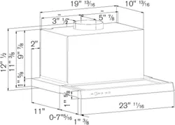
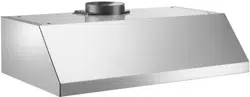
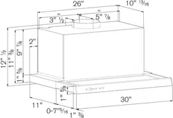
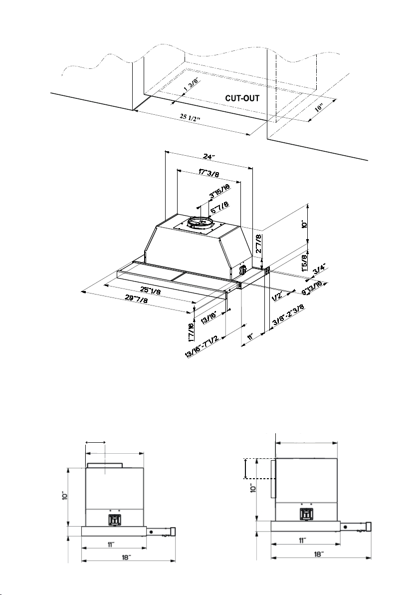
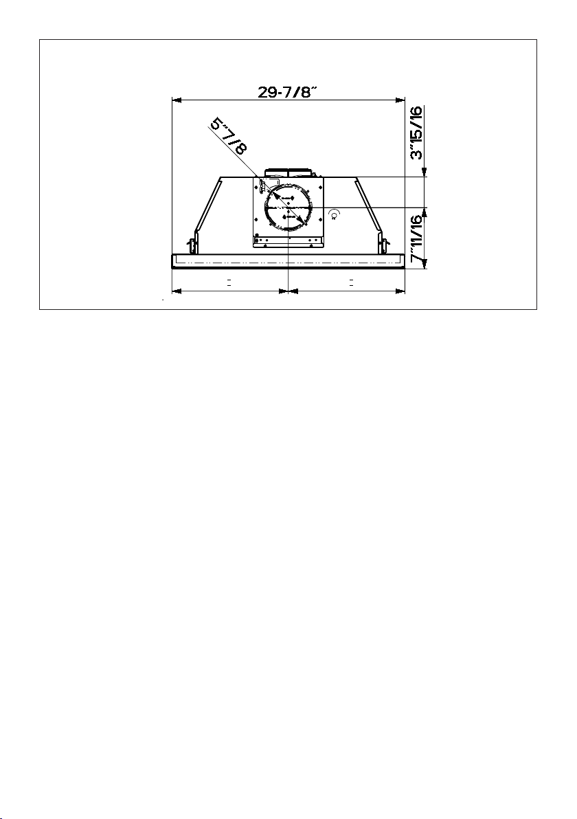
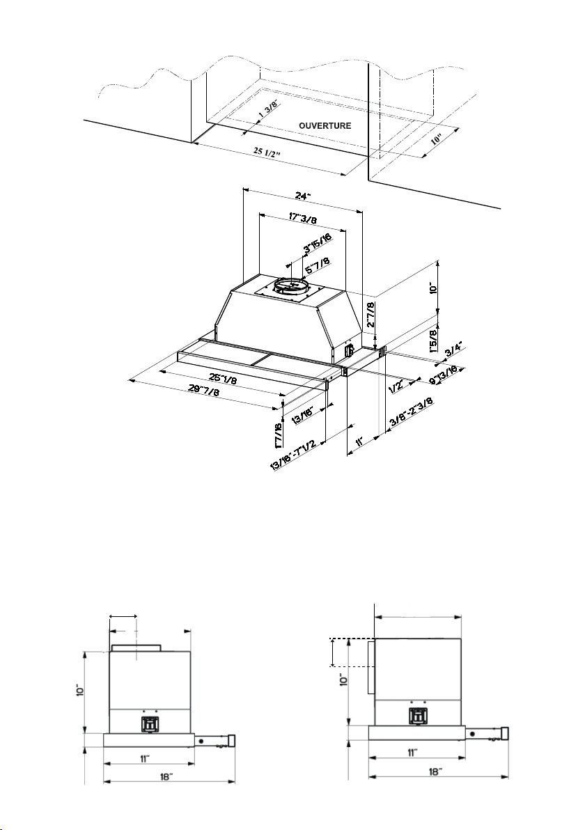
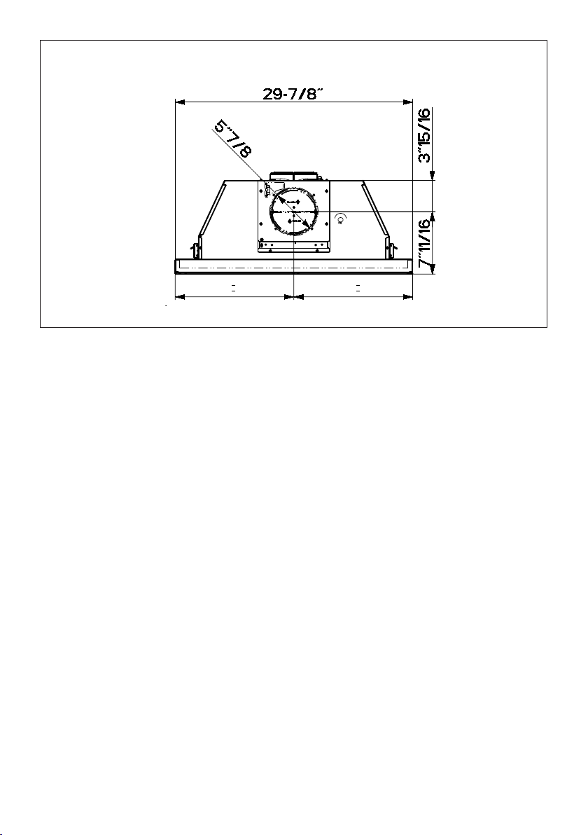
DIMENSIONS
Pre-Planning Your Installation - Important: The recommended height to install this hood off the
cooktop is a minimum of 24" and a maximum of 30” for maximum effectiveness. Also consult the cooktop
manufacturer’s recommendation. NOTE: If direct rear venting, use the side dimensional diagram
below on the right. For top venting (comes standard in this position), use the left dimensional
diagram. Refer to page 5 for directions for direct rear venting.
3 15/16”
7239(1767$1'$5'
',5(&75($59(17237,21
3 15/16”
1 5/8”
9 13/16”
9 13/16”
1 5/8”
6
30" RANGEHOOD REAR INFORMATION
DRAFT 25-MAY-2020 18:52
7
TOOLS NEEDED FOR INSTALLATION
• Saber Saw or Jig Saw
• Drill
• 1 1/4" Wood Drill Bit
• Pliers
• Phillips Screwdriver
• Wire Stripper or Utility Knife
• Metal Snips
• Measuring Tape or Ruler
• Level
• Pencil
• Caulking Gun
• Duct Tape
PARTS SUPPLIED FOR INSTALLATION
• 1 Backdraft Damper
• 1 Vent Grate (for recirculating installations only)
• 1 Vinyl Trim
• 1 Literature Package
PARTS NEEDED FOR INSTALLATION
• 2 Conduit Connectors
• Power Supply Cable
• 1 Wall or Roof Cap
• All Metal Ductwork
PLAN THE DUCTWORK
The KTV30XV slideout rangehood is designed
to offer wide exibility of installations. The
rangehood can be ducted vertically or
horizontally through a 6" round vent. The
unit can also be installed in a recirculating
conguration. The unit comes standard in
the top venting position. FIGURES 1 and
2 show vertical and horizontal installations
for this unit. FIGURE 3 shows recirculating
installation.
The KTV30XV requires 6" round ductwork. To
ensure that the blower performs to its highest
possible capacity, ductwork should be as
short and straight as possilbe.
For satisfactory performance the duct run
should not exceed 50 equivalent feet if
ducted using the
required minimum 6" round duct. The
equivalent feet in FIGURE A for each piece
of duct in the system An example is given
in FIGURE B. For best results, use no
more than three 90° elbows. Make sure
that there is a minimum of 24" of straight
duct between elbows if more than one is
used. Do not install two elbows together.
If you must elbow right away, do it as far
away from the hood's exhaust opening as
possible.
45˚ Elbow
90˚ Elbow
90˚ Flat Elbow
Wall Cap
3.0 feet
5.0 feet
12.0 feet
0.0 feet
FIGURE A
9 Feet Straight Duct
2 - 90˚ Elbows
Wall Cap
Total System
9.0 feet
10.0 feet
0.0 feet
19.0 feet
FIGURE B

8
Version 06/14 - Page 5
9.0 feet
10.0 feet
0.0 feet
19.0 feet
TOOLS NEEDED FOR INSTALLATION
• Saber Saw or Jig Saw
• Drill
• 1 1/4" Wood Drill Bit
• Pliers
• Phillips Screwdriver
• Wire Stripper or Utility Knife
• Metal Snips
• Measuring Tape or Ruler
• Level
• Pencil
• Caulking Gun
• Duct Tape
PARTS SUPPLIED FOR INSTALLATION
• 1 Backdraft Damper
• 1 Vent Grate (for recirculating installations only)
• 1 Vinyl Trim
• 1 Literature Package
PARTS NEEDED FOR INSTALLATION
• 2 Conduit Connectors
• Power Supply Cable
• 1 Wall or Roof Cap
• All Metal Ductwork
PLAN THE DUCTWORK
The Cristal HC slideout rangehood is designed to offer wide exibility of installations.
The rangehood can be ducted vertically or horizontally through a 6" round vent.
The unit can also be installed in a recirculating conguration. The unit comes
standard in the top venting position. FIGURES 1 and 2 show vertical and horizontal
installations for this unit. FIGURE 3 shows recirculating installation.
The Cristal HC requires 6" round ductwork. To ensure that the blower performs to
its highest possible capacity, ductwork should be as short and straight as possilbe.
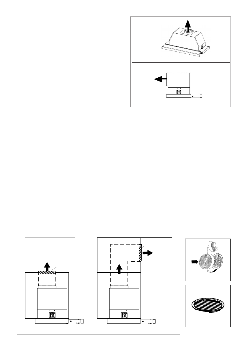
RECIRCULATING INSTALLATIONS
For recirculating installations (FIGURE 3), Charcoal Filters are necessary. Remove all four grease lters and set aside. Attach
one charcoal lter to each end of the blower. Each charcoal lter attaches to the black grid on the side of the blower. Rotate
the lter clockwise to install and counterclockwise to remove (FIGURE 3A). Replace all four grease lters. Some ductwork
must be installed to exhaust the rangehood back into the kitchen, either at the top of the cabinet or at the face of the soft. A
plastic vent grate (FIGURE 3B) supplied with the rangehood can be used to cover the duct opening. This duct work must not
terminate into a dead air space.
FIGURE 3A
45˚ Elbow
90˚ Elbow
90˚ Flat Elbow
Wall Cap
FIGURE A
9 Feet Straight Duct
2 - 90˚ Elbows
Wall Cap
Total System
FIGURE B
3.0 feet
5.0 feet
12.0 feet
0.0 feet
VERTICAL
DUCTING
FIGURE 2
HORIZONTAL
DUCTING
FIGURE 1
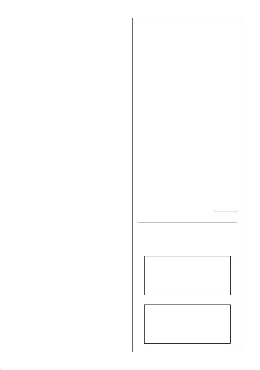
For direct rear venting (FIGURE 2), you must
change the blower position. Remove the 12
screws that hold the metal housing to the
rangehood body. Remove the 4 screws that
hold the blower housing to the metal housing.
Rotate the blower 90 degrees toward the back
and then ip it over 180 degrees. Be sure that
the power supply cable is properly positioned.
Replace all screws, making sure that they are
rmly fastened.
cabinet
ceiling
6” round
duct
hood
cabinet
ceiling
6” round
duct
hood
soft
vent grate
vent grate
FIGURE 3B
FIGURE 3
For satisfactory performance the duct run should
not exceed 50 equivalent feet if ducted using the
required minimum 6" round duct. The equivalent
feet in FIGURE A for each piece of duct in the
system An example is given in FIGURE B. For
best results, use no more than three 90°
elbows. Make sure that there is a minimum of
24" of straight duct between elbows if more
than one is used. Do not install two elbows
together. If you must elbow right away, do it
as far away from the hood's exhaust opening
as possible.
RECIRCULATING INSTALLATIONS
For recirculating installations (FIGURE 3), Charcoal Filters are necessary. Remove all four grease lters and
set aside. Attach one charcoal lter to each end of the blower. Each charcoal lter attaches to the black grid
on the side of the blower. Rotate the lter clockwise to install and counterclockwise to remove (FIGURE 3A).
Replace all four grease lters. Some ductwork must be installed to exhaust the rangehood back into the
kitchen, either at the top of the cabinet or at the face of the soft. A plastic vent grate (FIGURE 3B) supplied with
the rangehood can be used to cover the duct opening. This duct work must not terminate into a dead air space.
For direct rear venting (FIGURE 2), you must
change the blower position. Remove the 12 screws
that hold the metal housing to the rangehood
body. Remove the 4 screws that hold the blower
housing to the metal housing. Rotate the blower
90 degrees toward the back and then ip it over
180 degrees. Be sure that the power supply cable
is properly positioned. Replace all screws, making
sure that they are rmly fastened.
FIGURE 1
FIGURE 2
Version 06/14 - Page 5
9.0 feet
10.0 feet
0.0 feet
19.0 feet
TOOLS NEEDED FOR INSTALLATION
• Saber Saw or Jig Saw
• Drill
• 1 1/4" Wood Drill Bit
• Pliers
• Phillips Screwdriver
• Wire Stripper or Utility Knife
• Metal Snips
• Measuring Tape or Ruler
• Level
• Pencil
• Caulking Gun
• Duct Tape
PARTS SUPPLIED FOR INSTALLATION
• 1 Backdraft Damper
• 1 Vent Grate (for recirculating installations only)
• 1 Vinyl Trim
• 1 Literature Package
PARTS NEEDED FOR INSTALLATION
• 2 Conduit Connectors
• Power Supply Cable
• 1 Wall or Roof Cap
• All Metal Ductwork
PLAN THE DUCTWORK
The Cristal HC slideout rangehood is designed to offer wide exibility of installations.
The rangehood can be ducted vertically or horizontally through a 6" round vent.
The unit can also be installed in a recirculating conguration. The unit comes
standard in the top venting position. FIGURES 1 and 2 show vertical and horizontal
installations for this unit. FIGURE 3 shows recirculating installation.
The Cristal HC requires 6" round ductwork. To ensure that the blower performs to
its highest possible capacity, ductwork should be as short and straight as possilbe.
RECIRCULATING INSTALLATIONS
For recirculating installations (FIGURE 3), Charcoal Filters are necessary. Remove all four grease lters and set aside. Attach
one charcoal lter to each end of the blower. Each charcoal lter attaches to the black grid on the side of the blower. Rotate
the lter clockwise to install and counterclockwise to remove (FIGURE 3A). Replace all four grease lters. Some ductwork
must be installed to exhaust the rangehood back into the kitchen, either at the top of the cabinet or at the face of the soft. A
plastic vent grate (FIGURE 3B) supplied with the rangehood can be used to cover the duct opening. This duct work must not
terminate into a dead air space.
FIGURE 3A
45˚ Elbow
90˚ Elbow
90˚ Flat Elbow
Wall Cap
FIGURE A
9 Feet Straight Duct
2 - 90˚ Elbows
Wall Cap
Total System
FIGURE B
3.0 feet
5.0 feet
12.0 feet
0.0 feet
VERTICAL
DUCTING
FIGURE 2
HORIZONTAL
DUCTING
FIGURE 1
For direct rear venting (FIGURE 2), you must
change the blower position. Remove the 12
screws that hold the metal housing to the
rangehood body. Remove the 4 screws that
hold the blower housing to the metal housing.
Rotate the blower 90 degrees toward the back
and then ip it over 180 degrees. Be sure that
the power supply cable is properly positioned.
Replace all screws, making sure that they are
rmly fastened.
cabinet
ceiling
6” round
duct
hood
cabinet
ceiling
6” round
duct
hood
soft
vent grate
vent grate
FIGURE 3B
FIGURE 3
For satisfactory performance the duct run should
not exceed 50 equivalent feet if ducted using the
required minimum 6" round duct. The equivalent
feet in FIGURE A for each piece of duct in the
system An example is given in FIGURE B. For
best results, use no more than three 90°
elbows. Make sure that there is a minimum of
24" of straight duct between elbows if more
than one is used. Do not install two elbows
together. If you must elbow right away, do it
as far away from the hood's exhaust opening
as possible.
9
Version 06/14 - Page 7
INSTALL THE RANGEHOOD
1. Remove the rangehood from the carton and place on a
at surface. Cover the surface to prevent accidental damage.
Remove all parts including the backdraft damper, plastic grille
and literature package before discarding the carton. Remove
the grease lters and set aside.
2. Place the round damper into the exhaust opening of the
rangehood and press down.
FIGURE 5
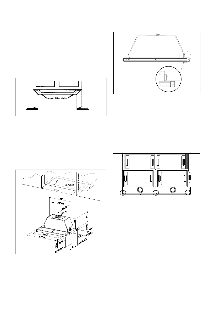
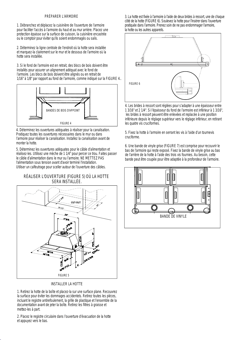
3. The rangehood mounts to the cabinet by two spring loaded
brackets, one on each side of the rangehood (FIGURE 6). Lift
the rangehood into the cutout opening in the cabinet. Be careful
not to damage the cabinet, rangehood or other appliances.
CUT-OUT
PREPARE THE CABINET
1. Disconnect and move freestanding range from cabinet
opening to provide easier access to upper cabinet and rear wall.
Put a thick, protective covering over cooktops, set-in ranges or
countertops to protect from damage or dirt.
2. Determine and clearly mark with a pencil the center line
of the cabinet on the wall and on the underside of the cabinet
where the rangehood will be installed.
3. If the cabinet bottom is recessed, wood blocks need to
be installed to insure proper alignment with the cabinet bottom.
Wood blocks should be ush or recessed 1/16" to 1/8" within
the cabinet bottom as indicated in FIGURE 4.
FIGURE 4
MAKE THE CUT-OUT OPENING (FIGURE 5)
WHERE THE RANGEHOOD WILL BE INSTALLED.
4. Determine the proper cutouts for the ductwork. Make all
necessary cuts in the walls or cabinets for the ductwork. Install
the ductwork before mounting the rangehood.
5. Determine and make the proper cutout for the Power Supply
Cable. Use a 1 1/4" Drill Bit to make this hole. Run the Power
Supply Cable through the wall or cabinet. DO NOT turn on the
power until installation is complete. Use caulking to seal around
the wire opening.
FIGURE 6
4. The spring loaded brackets are factory set to accomo-
date a thickness between 1 3/16" and 2 1/4". If your cabinet
bottom is less than 1 3/16" thick, the spring loaded brackets
can be removed and repositioned down from the top setting
to the bottom setting by removing the four phillips screws.
5. Tighten the rangehood to the cabinet by rotating the
screws with a phillips screw driver.
6. A grey vinyl strip (FIGURE 7) is included to cover the
underside of any remaining exposed cabinet. Attach the grey
vinyl strip to the bottom of the back of the rangehood with the
three screws provided. If necessary, the strip can be cut to
t the cabinet depth.
7. Remove the cover from the eld wiring compartment with
a phillips screwdriver. Feed the Power Supply Cable through
the electrical knockout. Connect the Power Supply Cable to the
rangehood cable. Attach the White lead of the power supply
to the White lead of the rangehood with a twist-on type wire
connector. Attach the Black lead of the power supply to the
Black lead of the rangehood with a twist-on type wire connector.
Attach the Power Supply Cable grounding lead to the green
screw provided. Using the 4 holes provided, screw the eld
wiring compartment to the wall or cabinet as dictated by your
Power Supply Cable location (screws not provided). Replace
the cover.
8. Replace the grease lters. Connect the ductwork to the
damper and seal all connections.
9. Turn the power supply on. Turn on the blower and light.
If the rangehood does not operate, check that the circuit breaker
is not tripped or the house fuse blown. If the unit still does
not operate, disconnect the power supply and check that the
wiring connections have been made properly.
FIGURE 7
VINYL STRIP
25 1/2” - 31 1/2”
10”
25 1/2” - 31 1/2”
13/16”
17 1/2” - 23 1/2”
5 7/8”
DRAFT 25-MAY-2020 18:52
10
7
Max. 33 7/16”
GROUNDING INSTRUCTIONS This appliance must
be grounded. In the event of an electrical short circuit,
grounding reduces the risk of electric shock by providing
an escape wire for the electric current. This appliance
is equipped with a cord having a grounding wire with
a grounding plug. The plug must be plugged into an
outlet that is properly installed and grounded.
WARNING - Improper grounding can result in a risk
of electric shock.
Consult a qualied electrician if the grounding instruc-
tions are not completely understood, or if doubt exists
as to whether the appliance is properly grounded.
Do not use an extension cord. If the power supply cord
is too short, have a qualied electrician install an outlet
near the appliance.
ELECTRICAL INSTALLATION
WITH CONNECTION CABLE
11
USE AND CARE INFORMATION
For Best Results
Start the rangehood several minutes before cooking to develop proper airow. Allow the
rangehood to operate for several minutes after cooking is complete to clear all smoke and
odors from the kitchen.
Version 06/14 - Page 8
USE AND CARE INFORMATION
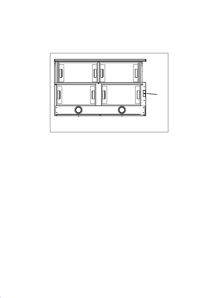
Rangehood Control Panel
All controls are located on the right side of the rangehood.
Light On/Off Switch
TheOn/Off switch for the halogen light is located behind the
front trim. Moving the switch to the 1 Position turns the light
On. Moving the switch to the 0 position turns the light off.
Blower Speed Switch
B in FIGURE 10 shows the speed control switch for the
blower. Moving the switch to the 1 Position turns the blower
on LOW. Moving the switch to the 2 Position turns the blower
on MEDIUM. Moving the switch to the 3 Position turns the
blower on HIGH. Moving the switch to the 0 Position turns
the blower off.
Automatic Operation
As long as the blower and light switches are on, the blower
and light will automatically operate when the visor is opened
and shut off when the visor is closed.
For Best Results
Start the rangehood several minutes before cooking to develop
proper airow. Allow the unit to operate for several minutes
after cooking is complete to clear all smoke and odors from
the kitchen.
Cleaning
The metal grease lters should be cleaned frequently in hot
detergent solution or placed in the dishwasher. Clean exterior
surfaces with hot soapy water. Using abrasives and scouring
agents can scratch rangehood nishes and should not be
used to clean nished surfaces.
Replacing the halogen lamp
CAUTION the bulb MAY BE HOT
To replace the halogen bulb, see (Figure 11)
Before attempting to replace the lamp, make sure the light
switch is off, the bulb CAUTION may be hot. Remove the
cover snap-on lamp levering under the metal ring, supporting
it with one hand. Remove the halogen lamp from the lamp
holder by pulling gently. Replace the lamp with a new one of
the same type, making sure that you insert the two pins into
the slots on the lamp holder. Replace the cover snap-on lamp.
FIGURE 10
FRONT TRIM OPTIONS
The Cristal HC comes with a stainless front strip installed.
Optional black and white strips are available as accessories
for purchase. To change the front strip, remove the three phil-
lips screws located behind the strip (FIGURE 8). If necessary,
the front strip can be adjusted by loosening the three phillips
screws and sliding the strip up or down. Tighten screws when
you have the strip properly placed.
For a custom front strip, a local cabinet shop can make a strip
to match your cabinets. The front strip dimensions are given
in FIGURE 9.
FIGURE 8
1 15/32"
FIGURE 9
3/4"
29 7/8" or 35 7/8"
Visor
Front
Strip
Three Screws
B
2x
FIGURE 11
Rangehood Control Panel
All controls are located on the right side of the rangehood.
Light On/Off Switch
TheOn/Off switch for the led light is located behind the front trim. Moving the switch to the 1
Position turns the light On. Moving the switch to the 0 position turns the light off.
Blower Speed Switch
B in FIGURE 10 shows the speed control switch for the blower. Moving the switch to the 1
Position turns the blower on LOW. Moving the switch to the 2 Position turns the blower on
MEDIUM. Moving the switch to the 3 Position turns the blower on HIGH. Moving the switch
to the 0 Position turns the blower off.
Automatic Operation
As long as the blower and light switches are on, the blower and light will automatically operate
when the visor is opened and shut off when the visor is closed.
12
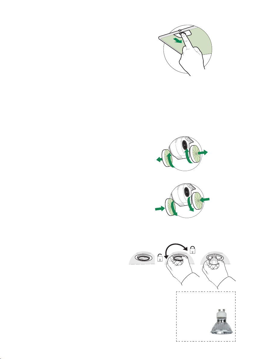
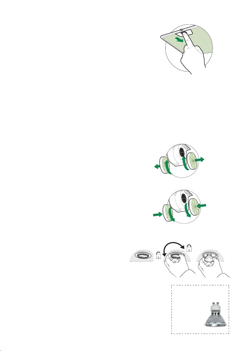
Cleaningmetalgreaselters
The metal grease lters can be cleaned in hot
detergent solution or washed in the dishwasher.
They should be cleaned every 2 months use, or
more frequently if use is particularly heavy.
• Open the visor by pulling it.
• Remove the lter, pushing the lever towards the
back of the unit and at the same time pulling
downward.
• Wash the lter without bending it, leave it to dry
thoroughly before replacing (if the surface of
the lter changes color over time, this will have
absolutely no effect on its efciency).
• Replace, taking care to ensure that the handle
faces forward.
• Cleaning in dishwasher may dull the nish of
the metal grease lter.
• Close the visor.
Replacing Activated Charcoal Filter
The Activated Charcoal Filters are not washable
and cannot be regenerated, and must be replaced
approximately every 4 months of operation, or
more frequently with heavy usage.
• Open the visor by pulling it.
• Remove the Filter, pushing it towards the back of
the unit and at the same time pulling downward.
• Remove the saturated Activated Charcoal Filters,
as indicated (A).
• Fit the new Filters, as indicated (B).
• Replace, taking care to ensure that the handle
faces forwards.
• Close the visor.
Lighting unit
• Turn off electrical supply before replacing bulbs,
and make sure bulbs are cool to touch before
proceeding.
• Remove the lamp at the base and turn slightly
to the left and the pull out from the connector
and turn slightly to the left.
• Replace the lamp with a new one of the same
type, making sure that you insert the two pins
properly into the housings on the lamp holder.
• Once the bulb pins are in place turn slightly to
the right to secure.
EN
7
7
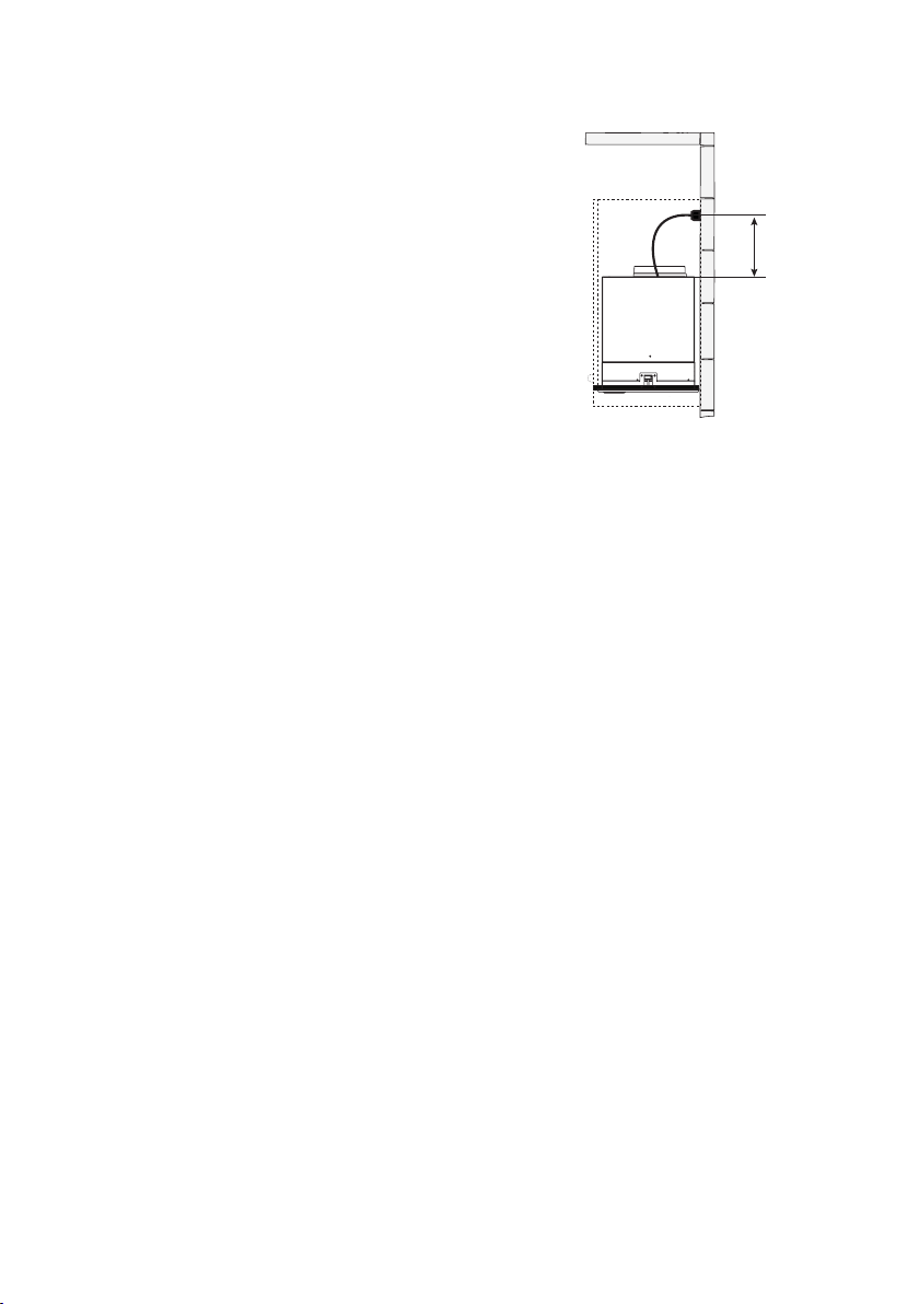
INSTALLATION
Fitting the Hood canopy
BEFORE FITTING THE HOOD TO THE WALL UNIT, PROCEED AS FOLLOWS:
• Disconnect the wires to the Commands at the connectors.
• Disconnect the wires to the Light at the con-
nectors.
• The Hood can be installed directly on the
underside of
the wall unit (Minimum 650 mm
from the Cooker Hob).
• Create an opening in the bottom of the wall unit,
as shown.
• Insert the hood until the side supports snap into
place.
• Fasten using the 10 screws 12a provided.
• Lock in position by tightening the screws Vf from
underneath the hood.
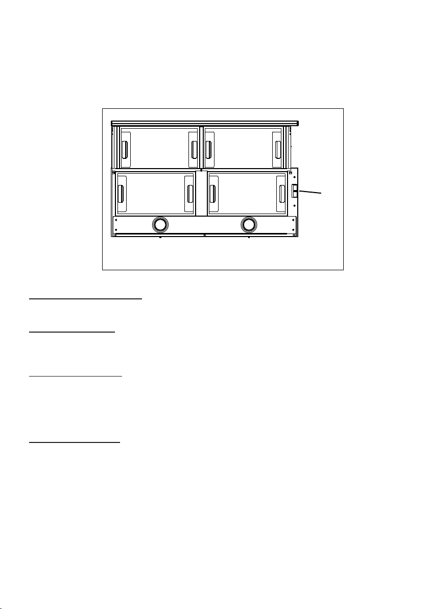
• Open the suction panel by turning the specific knob.
• Disconnect the panel from the hood canopy by sliding the
fixing pin lever.
• Remove grease filters.
• Screw the Frame into place
using the 6 scr
ews 12f, re-
connect the wires to the
Commands and Light, re-
place the metal grease filter
and the Panel.
260
13
495 - 675
Gu10 self-ballasted led
lamps – listed in ac-
cordance with
ul 1993/nmx-
j-578/1-ance/
csa c22.2 No.
1993

13
25
Pleasekindly register on our web site www.bertazzoni.com to validate your new product warranty
and help us to assist you better in case of anyinconvenience.
TWO YEAR LIMITED WARRANTY
The warranties provided byBertazzoniSpainthisstatementapply exclusivelyto Bertazzoniappliances and
accessories sold as new products to the original owner by a Bertazzoni authorized distributor, retailer,
dealer or service center and installed in the United States and Canada. The warranties provided in this
statement are not transferable and have validity from the date of installation.
COVERAGE INFORMATION
Bertazzoni SpA will repair or replace any component part which fails or proves defective due to
materials and/or workmanship within 2 years from the date of installation and under conditions of
normal residential use. Repair or replacement will be free of charge, including labor at standard rates
and shipping expenses. Repair service must be performed by a Bertazzoni Authorized Service
Center during normal working hours.
COSMETIC WARRANTY
Bertazzoni will cover parts showing cosmetic defects in material and workmanship for a period of thirty (30)
days from date of installation of the unit. This coverage will include scratches, stains, surface imperfections
on stainless steel,
paint and porcelain, with the exclusion of slight differences in color due to materials and
painting/enamelling technologies.
Exclusions are labor costs, B stock items, out‐of‐box appliances and display units.
HOW TO OBTAIN SERVICE
To obtain warranty service please contact Bertazzoni Customer Service at the numbers below and
provide model number, serial number and date of purchase.
ENGLISH 866 905 0010 ‐ FRANCAIS 800 561 7265
Save proof of original purchase or of original installation to establish warranty period. Copy of the product
serial tag is affixed to the back cover of the instruction manual.
WHAT IS NOT COVERED
1.The product used in any commercial/business application
2.Repair service provided by other than a Bertazzoni authorized service agent.
3.Damage or repair service to correct service provided by an unauthorized agency or the use of
unauthorized parts.
4.Installation not in accordance with local electrical codes or
plumbing codes.
5.Defects or damage due to improper storage of the product.
6 .Defects or damage or missing parts on products sold out of the original factory packaging or
from displays.
7.Service calls or repairs to correct the installation of the product and/or related accessories.
8.Service calls to connect, convert or otherwise repair the electrical wiring / gas line / water line to
properly use the product.
9.Service calls to provide instructions on the use of a Bertazzoni product.
10.Repair service due to product usage in manner other than what is normal and customary
for home use.
11.Replacement of wear and tear parts
12. Replacement of glasses andlight bulbs if they are claimed to have failed later than 30 days
after installation and in no case later than 4 months after date of purchase
13. Defects and damages arising fromaccident, alteration, misuse, abuse,
improper installation.
14. Defects and damages arising from transportation of the product to the home
of the owner.
15 .Defects and damage arising from external forces beyond the control of Bertazzoni SpA such
as fire, flood, earthquakes and other acts of God.
In case the product will be installed in a remote area, where certified trained technicians are not
reasonably available, the customer will be responsible for the transportation costs for the
delivery of the product to the nearest authorized service center or for the displacement costs of
a certified trained technician.
Bertazzoni does not assume any responsibility for incidental or consequential damages.
Some states do not allow the exclusion or limitation of incidental or consequential damages, so the
above limitation or exclusion may not apply to you. This warranty gives you specific legal rights and you
may also have other rights which may vary from state to state or province to province.

14
VEUILLEZ LIRE ET CONSERVER LA PRÉSENTE NOTICE AVANT DE
COMMENCER L'INSTALLATION DE LA HOTTE DE CUISINE
AVERTISSEMENT:POURRÉDUIRELERISQUED'UNFEUDEGRAISSESURLATABLEDECUISSON:
a) Ne laissez jamais sans surveillance les éléments de la surface de cuisson à température élevée. Les
bouillonnements excessifs peuvent provoquer de la fumée et les débordements de graisse peuvent
s'enflammer. L'huile doit être chauffée lentement, à une température basse ou moyenne.
b) Assurez-vous de toujours mettre en marche le ventilateur de la hotte lorsque vous cuisinez à tem-
pératureélevéeoupréparezunmetsflambé(p.ex.crêpesSuzette,cerisesjubilé,bœufflambé).
c) Nettoyez régulièrement les ventilateurs d'aspiration. Assurez-vous de ne pas laisser de la graisse
s'accumuler sur le ventilateur ou le filtre.
d) Utilisez toujours des poêles et casseroles de la taille appropriée. Utilisez toujours des ustensiles de
cuisine de la taille adaptée à celle de l'élément chauffant.
AVERTISSEMENT:-POURPRÉVENIRLESBLESSURESENCASDEFEUDEGRAISSESURLATABLE
DECUISSON,SUIVEZLESRECOMMANDATIONSSUIVANTES*:
a) ÉTOUFFEZ LES FLAMMES à l'aide d'un couvercle hermétique, d'une plaque à biscuits ou d'un plateau
métallique, puis éteignez le brûleur. FAITES ATTENTION AUX BRÛLURES. Si le feu ne s'éteint pas
immédiatement, QUITTEZ LES LIEUX ET APPELEZ LES POMPIERS.
b) NE PRENEZ JAMAIS UNE CASSEROLE EN FLAMME - Vous pourriez vous brûler.
c) N'UTILISEZ JAMAIS DE L'EAU, ni un linge à vaisselle ou un torchon mouillé, pour éteindre le feu.
Cela pourrait provoquer une violente explosion de vapeur.
d)UtilisezunextincteurUNIQUEMENTsi:
1. Vous êtes certain qu'il s'agit d'un extincteur de classe ABC et que vous connaissez bien son
mode d'emploi.
2. Le feu est de faible intensité et se limite à l'endroit où il a démarré.
3. Les pompiers ont déjà été appelés.
4. Une voie de sortie se trouve derrière vous pendant que vous éteignez les flammes.
* D'après le guide «Kitchen Firesafety Tips» publié par la NFPA aux États-Unis
AVERTISSEMENT - POUR RÉDUIRE LE RISQUE D'INCENDIE OU DE CHOC ÉLECTRIQUE, n'utilisez
jamais ce ventilateur en association avec un dispositif de réglage de vitesse à semi-conducteurs.
AVERTISSEMENT - POUR RÉDUIRE LES RISQUES D'INCENDIE, DE CHOC ÉLECTRIQUE OU DE
BLESSURECORPORELLE,RESPECTEZLESINSTRUCTIONSSUIVANTES:
1. Utilisez cet appareil uniquement de la façon prévue par le fabricant. Pour toute question, com-
muniquez avec le fabricant.
2. Avant de procéder à l'entretien ou au nettoyage de l'appareil, coupez l'alimentation au niveau du
panneau électrique et verrouillez-le pour vous assurer que l'électricité n'est pas rétablie accidentel-
lement. S'il n'est pas possible de verrouiller le dispositif d'interruption de l'alimentation, affichez de
façon ferme et bien visible un avis de danger, par exemple à l'aide d'une étiquette sur le panneau.
ATTENTION:Destinéàunusagedeventilationgénéraleuniquement.N'utilisezpascedispositifpour
l'aspiration de vapeurs ou de matériaux dangereux ou explosifs.
AVERTISSEMENT - POUR RÉDUIRE LES RISQUES D'INCENDIE, DE CHOC ÉLECTRIQUE OU DE
BLESSURECORPORELLE,RESPECTEZLESINSTRUCTIONSSUIVANTES:
1. L'installation et le branchement électrique doivent être réalisés par un technicien qualifié et con-
formément à tous les codes et normes en vigueur, incluant ceux concernant la construction à
l'épreuve du feu.
2. Afin de garantir une combustion et une évacuation adéquates des gaz par les conduites de la che-
minée des appareils à combustion, une bonne aération est nécessaire pour éviter le refoulement.
Respectez les lignes directrices fournies par le fabricant du matériel chauffant, ainsi que les normes
desécuritécommecellespubliéesparlaNationalFireProtectionAssociation(NFPA)etlaAmerican
SocietyforHeating,RefrigerationandAirConditioningEngineers(ASHRAE)auxÉtats-Unis,ainsi
que les codes en vigueur dans votre région.
3. Lorsque vous faites une ouverture ou percez dans un mur ou le plafond, veillez à ne pas endom-
mager les fils électriques ou d'autres dispositifs cachés.

15
4. Les ventilateurs canalisés doivent toujours être raccordés à l'extérieur.
TOUTE OUVERTURE DANS LE MUR OU LE PLANCHER À PROXIMITÉ DE LA HOTTE DOIT
ÊTRE SCELLÉE.
Un espace libre d'au moins 24" est requis entre le bas de la hotte et la surface de cuisson ou le comptoir.
Cette hotte a été homologuée par l'UL à cette distance de la surface de cuisson.
L’espace libre minimal requis peut-être plus grand, selon la réglementation en matière de construction de votre
région. Pour les cuisinières à gaz et les cuisinières combinées, un espace minimal de 30" est recommandé
et pourrait être exigé.
Les armoires suspendues de chaque côté de l'appareil doivent se trouver à au moins 18" de la surface de
cuisson ou du comptoir. Consultez la notice d'installation de la surface de cuisson ou de la cuisinière fournie
par le fabricant avant de pratiquer des ouvertures.
INSTALLATION DANS UNE MAISON MOBILE L'installation de cette hotte doit être conforme à la Partie
3280 de la norme Manufactured Home Construction and Safety Standards, Title 24 CFR (précédemment
la partie 280 de la norme Federal Standard for Mobile Home Construction and Safety, Title 24, HUD).
Consultez la che technique électrique.
• Le système de ventilation DOIT déboucher à l'extérieur.
• NE FAITES PAS déboucher les conduits dans un grenier ou un autre endroit fermé.
• N'UTILISEZ PAS un clapet de sécheuse mural de 4po.
• Il n'est pas recommandé d'utiliser des conduits exibles.
• N'ENTRAVEZ PAS le ux de l'air de combustion et de ventilation.
• Le non-respect des exigences en matière de ventilation pourrait entraîner un incendie.
AVERTISSEMENT
!
CRITÈRES DE VENTILATION
Déterminez quelle méthode de ventilation est mieux adaptée à votre application. Les conduits peuvent passer
par le mur ou le toit.
Pour garantir une meilleure efficacité, la longueur des conduits et le nombre de coudes doivent être le plus
limités que possible. Le diamètre des conduits devrait être uniforme. N'installez pas deux coudes ensemble.
Utilisez un ruban pour canalisations afin de sceller tous les joints du système de conduits. Utilisez un calfeutrage
pour sceller les ouvertures dans le mur extérieur ou le plancher, autour du clapet.
Il n'est pas recommandé d'utiliser des conduits flexibles. Les conduits flexibles provoquent une contre-pression
et de la turbulence qui diminuent grandement l'efficacité de l'appareil.
Assurez-vous que l'espace libre dans le mur ou le plancher est suffisant pour le conduit d'évacuation avant de
pratiquer les ouvertures. Ne coupez jamais une poutre ou un chevron, sauf si c'est absolument nécessaire.
S'il s'avère nécessaire de couper une poutre ou un chevron, la construction d'un renforcement est requise.
AVERTISSEMENT - Pour réduire le risque d'incendie, utilisez uniquement des conduits métalliques.
ATTENTION - Pour réduire le risque d'incendie et pour évacuer adéquatement l'air, assurez-vous
deraccorderlesconduitsàl'extérieur–Nediffusezpasl'aird'évacuationdansdesespacesà
l'intérieur des murs ou du plafond, ou encore à l'intérieur d'un grenier, d'une galerie technique ou
d'un garage.
Installation dans les climats froids
Le système de ventilation doit prévoir un registre antirefoulement supplémentaire pour réduire le ux d'air
froid inverse, ainsi qu'une barrière thermique non métallique pour réduire la conduction des températures
extérieures. Le registre doit être installé du côté air froid par rapport à la barrière thermique. La barrière
thermique doit être positionnée le plus près que possible de l'endroit où le système de ventilation pénètre
dans la partie chauffée de la maison.

16
• Une mise à la terre électrique est requise pour cette hotte.
• N'UTILISEZ PAS un tuyau d'eau froide pour la mise à la terre si celui-ci est branché par des
joints en plastique, par des rondelles non métalliques ou d'autres matériaux.
• N'UTILISEZ PAS une conduite de gaz pour la mise à la terre.
• N'INSTALLEZ PAS un fusible sur le circuit neutre ou le circuit de mise à la terre. La présence
d'un fusible dans le circuit neutre ou de mise à la terre peut entraîner un choc électrique.
• Consultez un électricien qualié si vous n'êtes pas certain de la mise à la terre de la hotte.
• Le non-respect des exigences de la che technique électrique pourrait entraîner un incendie.
AVERTISSEMENT
!
Avertissementdelaproposition65del'ÉtatdeCalifornie(USseulement)
ATTENTION
Ce produit contient des produits chimiques connus de l'État de Californie pour causer le
cancer et des malformations congénitales ou d'autres problèmes de reproduction.
Pour plus d'informations, visitez www.P65Warnings.ca.gov
FICHE TECHNIQUE ÉLECTRIQUE
Une alimentation de courant alternatif de 120 volts à 60Hz est requise sur un circuit à
fusible distinct de 15 ampères. Il est recommandé d'installer un fusible temporisé ou
un disjoncteur. Le fusible doit être calibré conformément aux codes en vigueur pour les
caractéristiques nominales électriques de l'appareil, indiquées sur la plaque signalétique
située à l'intérieur de l'appareil, à proximité du compartiment des câblages externes.
17
DIMENSIONS
Planication de l’installation - Important : Il est recommandé d'installer cette hotte à une distance
d'au moins 24" de la surface de cuisson et à une distance maximale de 30” pour une efcacité optimale.
Reportez-vous également aux recommandations du fabricant de la surface de cuisson. REMARQUE
: En cas de ventilation directement à l’arrière, utilisez le diagramme des dimensions latérales
de droite. En cas de ventilation vers le haut (position standard), utiliser le diagramme des
dimensions de gauche. Reportez-vous à la page 16 pour de plus amples renseignements sur la
ventilation directement à l’arrière.
DRAFT 25-MAY-2020 18:52
3 15/16”
7239(1767$1'$5'
',5(&75($59(17237,21
3 15/16”
1 5/8”
9 13/16”
9 13/16”
1 5/8”
18
INFORMATIONS ARRIÈRE HOTTE 30"
DRAFT 25-MAY-2020 18:52
19
OUTILS REQUIS POUR L’INSTALLATION
• Scie sauteuse ou scie à découper
• Perceuse
• Mèche pour bois de 1 1/4"
• Pinces
• Tournevis cruciforme
• Dénudeur de l ou couteau tout usage
• Cisailles à métaux
• Ruban à mesurer ou règle
• Niveau
• Crayon
• Pistolet de calfeutrage
• Ruban pour canalisation
PIÈCES FOURNIES POUR
L’INSTALLATION
• 1 registre antirefoulement
• 1 grille d’évent (pour installation avec recyclage
uniquement)
• 1 garniture de vinyle
• 1 documentation
PIÈCES REQUISES POUR
L’INSTALLATION
• 2 connecteurs de conduit
• Câble d’alimentation électrique
• 1 clapet mural ou clapet de toiture
• Canalisation entièrement métallique
PLANIFIER LA CANALISATION
La hotte coulissante KTV30XV est conçue
pour offrir une grande exibilité en matière
d’installation. Il est possible d’installer une
canalisation verticale ou horizontale, par un
conduit circulaire de 6". Il est aussi possible
d’installer l’appareil en le congurant de
façon à ce que l’air soit recyclé. L’appareil
est conguré en vue d’une installation
avec canalisation verticale par défaut. Les
FIGURES 1 et 2 illustrent l’installation verticale
et horizontale de l’appareil. La FIGURE 3
illustre l’installation avec recyclage.
La hotte KTV30XV nécessite des conduits
circulaires de 6". La canalisation doit être la
plus courte et droite que possible, pour que
le ventilateur fonctionne au maximum de ses
capacités.
Pour des résultats satisfaisants, la
canalisation ne devrait pas être supérieure à
l’équivalent de 50 pieds si la canalisation est
réalisée avec le conduit circulaire minimum de
6". L’équivalent en pieds de chaque élément
de canalisation du système de la FIGURE
A. Un exemple est donné sur la FIGURE B.
Pour des résultats optimaux, n’utilisez pas
plus de trois coudes de 90°. Si plus d’un
coude est utilisé, assurez-vous qu’un
conduit linéaire d’une longueur minimale
de 24" se trouve entre deux coudes.
N’installez pas deux coudes ensemble.
Si vous devez installer tout de suite un
coude, placez-le le plus loin possible de
l’ouverture d’évacuation de la hotte.
45˚ Coude
90˚ Coude
90˚ Coude plat
Clapet mural
3.0 pieds
5.0 pieds
12.0 pieds
0.0 pieds
FIGURE A
Conduit droit de 9 pieds
2 - 90˚ coudes
Clapet mural
Système total
9.0 pieds
10.0 pieds
0.0 pieds
19.0 pieds
FIGURE B
20
INSTALLATIONS AVEC RECYCLAGE
Pour les installations avec recyclage (FIGURE 3), il est nécessaire d'installer des ltres à charbon. Retirez les
quatre ltres à graisse et mettez-les à part. Posez un ltre à charbon à chaque extrémité du ventilateur. Chaque
ltre à charbon se xe à la grille noire sur le côté du ventilateur. Faites tourner le ltre dans le sens des aiguilles
d'une montre pour l'installer et dans le sens contraire des aiguilles d'une montre pour l'enlever (FIGURE 3A).
Remettez les quatre ltres à graisse en place. Une canalisation doit être installée pour évacuer la hotte dans
la cuisine, soit au sommet des armoires ou sur la face du parement. Une grille d’évent de plastique (FIGURE
3B) fournie avec la hotte peut être utilisée pour couvrir l’ouverture du conduit. Cette canalisation ne doit pas se
terminer dans un espace sans circulation d'air.
Pour la ventilation directement à l’arrière (FIGURE
2), vous devez changer la position du ventilateur.
Retirez les 12 vis qui relient le carter de métal
au bâti de la hotte. Retirez les 4 vis qui relient le
carter du ventilateur au carter de métal. Faites
tourner le ventilateur de 90 degrés vers l’arrière,
puis faites-le tourner de 180 degrés. Assurez-vous
que le câble d’alimentation électrique est dans
une position adéquate. Remettez toutes les vis en
place, en vous assurant qu’elles sont bien serrées.
FIGURE 1
FIGURE 2
Version 06/14 - Page 5
9.0 pieds
10.0 pieds
0.0 pieds
19.0 pieds
OUTILS REQUIS POUR L’INSTALLATION
•Scie sauteuse ou scie à découper
•Perceuse
•Mèche pour bois de 1 1/4"
•Pinces
•Tournevis cruciforme
•Dénudeur de fil ou couteau tout usage
•Cisailles à métaux
•Ruban à mesurer ou règle
•Niveau
•Crayon
•Pistolet de calfeutrage
•Ruban pour canalisation
PIÈCES FOURNIES POUR L’INSTALLATION
PIÈCES REQUISES POUR L’INSTALLATION
• 2 connecteurs de conduit
• Câble d’alimentation électrique
• 1 clapet mural ou clapet de toiture
• Canalisation entièrement métallique
PLANIFIER LA CANALISATION
INSTALLATIONS AVEC RECYCLAGE
FIGURE 3A
45˚ Coude
90˚ Coude
90˚ Coude plat
Clapet mural
FIGURE A
Conduit droit de 9 pieds
2 - 90˚ coudes
Clapet mural
Système total
FIGURE B
3.0 pieds
5.0 pieds
12.0 pieds
0.0 pieds
CANALISATION
VERTICALE
FIGURE 2
CANALISATION
HORIZONTALE
FIGURE 1
armoire
plafond
conduit circulaire de 6”
hotte
armoire
plafond
conduit circulaire de 6”
hotte
grille d’évent
grille d’évent
FIGURE 3B
FIGURE 3
La hotte coulissante Cristal HC est conçue pour offrir une grande flexibilité en matière d’installation.
Il est possible d’installer une canalisation verticale ou horizontale, par un conduit circulaire de 6".
Il est aussi possible d’installer l’appareil en le configurant de façon à ce que l’air soit recyclé.
L’appareil est configuré en vue d’une installation avec canalisation verticale par défaut.
Les FIGURES 1 et 2 illustrent l’installation verticale et horizontale de l’appareil. La FIGURE 3 illustre
l’installation avec recyclage. La hotte Cristal HC nécessite des conduits circulaires de 6".
La canalisation doit être la plus courte et droite que possible, pour que le ventilateur fonctionne au
maximum de ses capacités.
•1 registre antirefoulement
•1 grille d’évent (pour installation avec recyclage
uniquement)
•1 garniture de vinyle
•1 documentation
Pour des résultats satisfaisants, la canalisation ne devrait
pas être supérieure à l’équivalent de 50 pieds si la
canalisation est réalisée avec le conduit circulaire minimum
de 6". L’équivalent en pieds de chaque élément de
canalisation du système de la FIGURE A.
Un exemple est donné sur la FIGURE B.
Pour des résultats optimaux, n’utilisez pas plus de trois
coudes de 90°. Si plus d’un coude est utilisé, assurez-vous
qu’un conduit linéaire d’une longueur minimale de 24" se
trouve entre deux coudes. N’installez pas deux coudes
ensemble. Si vous devez installer tout de suite un coude,
placez-le le plus loin possible de l’ouverture d’évacuation de
la hotte.
Pour la ventilation directement à l’arrière (FIGURE 2), vous
devez changer la position du ventilateur. Retirez les 12 vis
qui relient le carter de métal au bâti de la hotte.
Retirez les 4 vis qui relient le carter du ventilateur au carter
de métal. Faites tourner le ventilateur de 90 degrés vers
l’arrière, puis faites-le tourner de 180 degrés.
Assurez-vous que le câble d’alimentation électrique est dans
une position adéquate. Remettez toutes les vis en place,
en vous assurant qu’elles sont bien serrées.
Pour les installations avec recyclage (FIGURE 3), il est nécessaire d'installer des filtres à charbon. Retirez les quatre filtres à graisse et mettez-les à part. Posez
un filtre à charbon à chaque extrémité du ventilateur. Chaque filtre à charbon se fixe à la grille noire sur le côté du ventilateur. Faites tourner le filtre dans le sens
des aiguilles d'une montre pour l'installer et dans le sens contraire des aiguilles d'une montre pour l'enlever (FIGURE 3A). Remettez les quatre filtres à graisse
en place. Une canalisation doit être installée pour évacuer la hotte dans la cuisine, soit au sommet des armoires ou sur la face du parement. Une grille d’évent
de plastique (FIGURE 3B) fournie avec la hotte peut être utilisée pour couvrir l’ouverture du conduit. Cette canalisation ne doit pas se terminer dans un espace
sans circulation d'air.
21
INSTALLER LA HOTTE
1. Retirez la hotte de la boîte et placez-la sur une surface plane. Recouvrez
la surface pour éviter les dommages accidentels. Retirez toutes les pièces,
incluant le registre antirefoulement, la grille de plastique et l’ensemble de la
documentation avant de jeter la boîte. Retirez les filtres à graisse et
mettez-les à part.
2. Placez le registre circulaire dans l’ouverture d’évacuation de la hotte
et appuyez vers le bas.
FIGURE 5
3. La hotte est fixée à l’armoire à l’aide de deux brides à ressort, une de chaque
côté de la hotte (FIGURE 6). Soulevez la hotte pour l’insérer dans l’ouverture
pratiquée dans l’armoire. Prenez soin de ne pas endommager l’armoire,
la hotte ou les autres appareils.
OUVERTURE
PRÉPARER L’ARMOIRE
1. Débranchez et déplacez la cuisinière de l’ouverture de l’armoire
pour faciliter l’accès à l’armoire du haut et au mur arrière. Placez une
protection épaisse sur la surface de cuisson, la cuisinière encastrée
ou le comptoir pour éviter qu'ils soient endommagés ou salis.
2. Déterminez la ligne centrale de l’endroit où la hotte sera installée
et marquez-la clairement sur le mur et le dessous de l’armoire où la
hotte sera installée.
FIGURE 4
RÉALISER L’OUVERTURE (FIGURE 5) OÙ LA HOTTE
SERA INSTALLÉE.
4. Déterminez les ouvertures adéquates à réaliser pour la canalisation.
Pratiquez toutes les ouvertures nécessaires dans le mur ou dans
l’armoire pour réaliser la canalisation. Installez la canalisation avant de
monter la hotte.
5. Déterminez les ouvertures adéquates pour le câble d’alimentation et
réalisez-les. Utilisez une mèche de 1 1/4" pour percer ce trou. Faites passer
le câble d’alimentation dans le mur ou l’armoire. NE METTEZ PAS
l'alimentation sous tension avant d'avoir terminé l'installation.
Utiliser un calfeutrage pour sceller autour de l’ouverture des câbles.
FIGURE 6
4. Les brides à ressort sont réglées pour s’adapter à une épaisseur entre
1 3/16" et 2 1/4". Si l’épaisseur du fond de l’armoire est inférieur à 1 3/16",
les brides à ressort peuvent être enlevées et replacée à une position
inférieure depuis le réglage supérieur vers le réglage inférieur, en retirant
les quatre vis cruciformes.
5. Fixez la hotte à l’armoire en serrant les vis à l’aide d’un tournevis
cruciforme.
6. Une bande de vinyle grise (FIGURE 7) est comprise pour recouvrir le
bas de l’armoire qui reste exposé. Fixez la bande de vinyle grise au bas
de l’arrière de la hotte à l’aide des trois vis fournies. Au besoin, cette
bande peut être coupée pour être adaptée à la profondeur de l’armoire.
BANDE DE VINYLE
25 1/2” - 31 1/2”
10”
25 1/2” - 31 1/2”
13/16”
17 1/2” - 23 1/2”
5 7/8”
3. Si le fond de l’armoire est en retrait, des blocs de bois doivent être
installés pour assurer un alignement adéquat avec le fond de
l’armoire. Les blocs de bois doivent être alignés ou en retrait de
1/16" à 1/8" par rapport au fond de l’armoire, comme indiqué sur la FIGURE 4..
BANDES DE BOIS D’APPOINT
DRAFT 25-MAY-2020 18:52

22
7
Max. 33 7/16”
INSTRUCTIONS DE MISE À LA TERRE Cet appareil
doit être mis à la terre. La mise à la terre réduit le
risque de choc électrique en cas de court-circuit, car
elle fournit un l d'évacuation au courant électrique.
Cet appareil est muni d'un cordon présentant un l de
mise à la terre, avec une che de mise à la terre. La
che doit être insérée dans une prise correctement
installée et mise à la terre.
AVERTISSEMENT - Une mise à la terre inadéquate
peut entraîner un choc électrique.
Consultez un électricien qualié si vous ne comprenez
pas parfaitement les instructions de mise à la terre ou
si vous avez des doutes quant à la mise à la terre de
l'appareil.
N'utilisez pas de rallonge. Si le cordon d’alimentation est
trop court, demandez à un électricien qualié d’installer
une prise à proximité de l'appareil.
INSTALLATION ÉLECTRIQUE
AVEC CÂBLE DE CONNEXION
23
INFORMATIONS POUR L'UTILISATION ET L'ENTRETIEN
Pour de meilleurs résultats
Activez la hotte quelques minutes avant de commencer à cuisiner pour créer un ux d'air
adéquat. Laissez la hotte fonctionner quelques minutes après avoir ni de cuisiner pour
absorber toute la fumée et les odeurs de la cuisine.
Version 06/14 - Page 8
USE AND CARE INFORMATION
Rangehood Control Panel
All controls are located on the right side of the rangehood.
Light On/Off Switch
TheOn/Off switch for the halogen light is located behind the
front trim. Moving the switch to the 1 Position turns the light
On. Moving the switch to the 0 position turns the light off.
Blower Speed Switch
B in FIGURE 10 shows the speed control switch for the
blower. Moving the switch to the 1 Position turns the blower
on LOW. Moving the switch to the 2 Position turns the blower
on MEDIUM. Moving the switch to the 3 Position turns the
blower on HIGH. Moving the switch to the 0 Position turns
the blower off.
Automatic Operation
As long as the blower and light switches are on, the blower
and light will automatically operate when the visor is opened
and shut off when the visor is closed.
For Best Results
Start the rangehood several minutes before cooking to develop
proper airow. Allow the unit to operate for several minutes
after cooking is complete to clear all smoke and odors from
the kitchen.
Cleaning
The metal grease lters should be cleaned frequently in hot
detergent solution or placed in the dishwasher. Clean exterior
surfaces with hot soapy water. Using abrasives and scouring
agents can scratch rangehood nishes and should not be
used to clean nished surfaces.
Replacing the halogen lamp
CAUTION the bulb MAY BE HOT
To replace the halogen bulb, see (Figure 11)
Before attempting to replace the lamp, make sure the light
switch is off, the bulb CAUTION may be hot. Remove the
cover snap-on lamp levering under the metal ring, supporting
it with one hand. Remove the halogen lamp from the lamp
holder by pulling gently. Replace the lamp with a new one of
the same type, making sure that you insert the two pins into
the slots on the lamp holder. Replace the cover snap-on lamp.
FIGURE 10
FRONT TRIM OPTIONS
The Cristal HC comes with a stainless front strip installed.
Optional black and white strips are available as accessories
for purchase. To change the front strip, remove the three phil-
lips screws located behind the strip (FIGURE 8). If necessary,
the front strip can be adjusted by loosening the three phillips
screws and sliding the strip up or down. Tighten screws when
you have the strip properly placed.
For a custom front strip, a local cabinet shop can make a strip
to match your cabinets. The front strip dimensions are given
in FIGURE 9.
FIGURE 8
1 15/32"
FIGURE 9
3/4"
29 7/8" or 35 7/8"
Visor
Front
Strip
Three Screws
B
2x
FIGURE 11
Panneau de commande de la hotte
Toutes les commandes sont situées sur le côté droit de la hotte.
Interrupteur d’éclairage
L’interrupteur de l’éclairage DEL se trouve derrière la garniture avant. Placer l’interrupteur à la
position 1 pour allumer l’éclairage. Placer l’interrupteur à la position 0 pour éteindre l’éclairage.
Commutateur de réglage de vitesse du ventilateur
B sur la FIGURE 10 représente le commutateur de réglage de vitesse du ventilateur. Placer
le commutateur à la position 1 pour allumer le ventilateur à la vitesse RÉDUITE. Placer le
commutateur à la position 2 pour allumer le ventilateur à la vitesse MOYENNE. Placer le
commutateur à la position 3 pour allumer le ventilateur à la vitesse ÉLEVÉE. Placer l’inter-
rupteur à la position 0 pour éteindre le ventilateur.
Fonctionnement automatique
Si le commutateur du ventilateur et l’interrupteur de l’éclairage sont allumés, le ventilateur et
l’éclairage sont activés automatiquement quand le panneau coulissant est ouvert, et ils sont
désactivés quand le panneau coulissant est fermé.
24
Nettoyagedesltresàgraisse
métalliques
Les ltres à graisse métalliques peuvent être lavés
dans une solution d'eau chaude savonneuse ou
dans le lave-vaisselle. Ils devraient être nettoyés
tous les 2 mois d'utilisation, ou plus fréquemment
en cas d'utilisation particulièrement intensive.
• Ouvrez le panneau coulissant en le tirant.
• Retirez le ltre, en poussant simultanément le
levier vers l'arrière de l'appareil et en le tirant
vers le bas.
• Lavez le ltre sans le plier. Laissez-le sécher
complètement avant de le réinstaller (un
changement de la couleur à la surface du ltre au
l du temps n'a aucun impact sur son efcacité).
• Remettez-le en place, en vous assurant que la
poignée se trouve vers l'avant.
• Le lave-vaisselle pourrait ternir le ni du ltre à
graisse métallique.
• Fermez le panneau coulissant.
Remplacementdultreàcharbonactif
Les ltres à charbon actif ne sont pas lavables
et ne peuvent être régénérés. Ils doivent être
remplacés environ tous les 4 mois d'utilisation, ou
plus souvent en cas d'utilisation intensive.
• Ouvrez le panneau coulissant en le tirant.
• Retirez le ltre, en le poussant simultanément vers
l'arrière de l'appareil et en le tirant vers le bas.
• Retirez les ltres à charbon actif saturés comme
indiqué (A).
• Posez les nouveaux ltres, comme indiqué (B).
• Remettez-les en place, en vous assurant que la
poignée se trouve vers l'avant.
• Fermez le panneau coulissant.
Système d'éclairage
• Coupez l'alimentation électrique avant de
remplacer les ampoules et assurez-vous qu'elles
sont froides au toucher avant de commencer.
• Retirez l'ampoule de la base. Faites tourner
légèrement vers la gauche et retirez-la du socle.
• Remplacez l'ampoule avec une nouvelle du même
type, en vous assurant d'insérer correctement les
deux connecteurs dans leur logement sur le socle.
• Lorsque les connecteurs de l'ampoule sont en
place, faites tourner légèrement vers la droite
pour verrouiller.
EN
7
7
INSTALLATION
Fitting the Hood canopy
BEFORE FITTING THE HOOD TO THE WALL UNIT, PROCEED AS FOLLOWS:
• Disconnect the wires to the Commands at the connectors.
• Disconnect the wires to the Light at the con-
nectors.
• The Hood can be installed directly on the
underside of
the wall unit (Minimum 650 mm
from the Cooker Hob).
• Create an opening in the bottom of the wall unit,
as shown.
• Insert the hood until the side supports snap into
place.
• Fasten using the 10 screws 12a provided.
• Lock in position by tightening the screws Vf from
underneath the hood.
• Open the suction panel by turning the specific knob.
• Disconnect the panel from the hood canopy by sliding the
fixing pin lever.
• Remove grease filters.
• Screw the Frame into place
using the 6 scr
ews 12f, re-
connect the wires to the
Commands and Light, re-
place the metal grease filter
and the Panel.
260
13
495 - 675
Lampes DEL à ballast
intégré de type Gu10 –
répondant à
la norme UL
1993/nmx-j-
578/1-ance/
csa c22.2 No
1993

25
26
Nous Vous prions de bien vouloir vous enregistrer sur notre site web www.bertazzoni.com pour valider votre
garantie
du nouveau produit et nous aider à Vous aider dans le cas de dommages.
GARANTIE LIMITEE DE DEUX ANS
LesgarantiesoffertesparBertazzoniSpadanscettedéclarations’appliquentexclusivementauxappareils
et
composants Bertazzoni venduscomme neufs au propriétaire original par un distributeur,détaillant,
concessionnaire oucentre de service autoriséset installésauxEtats-Uniset Canada.Lesgaranties fournies dans
cettedéclaration ne
peuvent pas être transférées et sont valables à partir de la date d’installation.
INFORMATIONS SUR LA COUVERTURE
Bertazzoni SpA procédera à la réparation ou remplacera tout composantdéfectueux à cause des matériaux et/ou
fabrication
pendant2ansàcompterdeladated’installationetdanslesconditionsnormalesd’utilisationdansle
cadrefamilial. La réparationouleremplacementseronteffectuésàtitregratuitet inclurontlesfraisdemain
d’oeuvreau tarif normalet les
frais d’expédition. Les réparations doivent être effectuées par un Centre de Service
Bertazzoni Autorisé pendant les heures de travail normales. Les défauts doiventêtre signalés dans les 30 jours qui
suiventl’installation.Cette garantie ne couvre pas
l’utilisation du produit dans le cadre commercial.
GARANTIE ESTHETIQUE
Bertazzoni SpA couvre lespiècesprésentant des défauts cosmétiques de matériaux et de fabricationpour une
période
detrente(30)joursàcompterdeladated'installationdel'unité.Cettecouvertureincluralesrayures,
lestaches,les
imperfections de surface sur l'acier inoxydable, de la peinture et de la porcelaine, à l'exclusion de
légères différences
de couleur dûes à des matériaux et des technologies de peinture / émaillage.
Les coûts de main-d'oeuvre, B stock, appareils out-of-box et les unités d'affichage sont exclus
Pourobtenirleservicedegarantie, veuillezcontacter BertazzoniCustomer Serviceaux numérosindiquésci-
dessous et
fournir le numéro du modèle, le numéro de série et la date d’achat.
ANGLAIS 866 905 0010 FRANCAIS 800 561 7265
Il faut conserver la preuve d’achat ou l’origine de l’insta llation afin d’établir la période de garantie. Une copie
du
numéro de série sera collée derrière le manuel d’emploi.
CE QUI NE SERA PAS PRIS EN CHARGE
1.
Le produit utilisé dans toute application commerciale/commerciale.
2.
Service de réparation fourni par un agent de service autorisé autre que Bertazzoni.
3.
N’importe quel dommage ou service de réparation nécessaire pour corriger un service effectué par un agence
non
autorisé et/ou par suite d'utilisation de pièces non autorisés.
4.
Installation non conforme aux codes électriques locaux ou aux codes de plomberie.
5.
Les défauts ou dommages dûs à une mauvaise conservation du produit.
6.
Les défauts ou dommages et les pièces oubliées sur les produits vendus au dehors de l'emballage d'origine ou
d’
affichage.
7.
Les appels de service ou des réparations pour corriger l'installation du produit et / ou accessoires.
8.
Les appels de service pour se connecter, ou réparer le câblage électrique et / ou de gaz afin d'utiliser le
produit
d’une façon correcte.
9.
Les appels de service pour fournir des instructions sur l'utilisation d'un produit Bertazzoni.
10.
Service de réparation dû à une utilisation différente que celle standard et habituel à la maison.
11.
Remplacement des piècesd'usure
12.
Remplacement des verres et des ampoules si elles sont échoués au plus tard 30 jours après
l'installation et en
aucun cas plus tard 4 mois après la date d'achat
13.
Défauts et dommages résultant d'un accident, modification, mésusage, abus, mauvaise
installation.
14.
Défauts et dommages résultant du transport du produit à la maison du propriétaire.
15.
Les défauts et les dommages résultant de forces externes qui échappent au contrôle de Bertazzoni
SpA tels que les incendies, les inondations, les tremblements de terre et autres catastrophes naturelles. Au
cas où le produit sera installé dans une zone, là où techniciens qualifiés certifiés ne sont pas
raisonnablement disponibles, le client sera responsable des coûts de transport pour la livraison du
produit au centre de service autorisé le plus proche, ou pour les coûts de déplacement d'un
technicien qualifié certifié
Bertazzoni exclut toute responsabilité pour les dommages accidentels ou indirects. Certains pays
n’autorisent pas l’exclusion ou la limitation des dommages accidentels ou indirects, la limitation indiquée
plus haute peut donc ne pas s’appliquer à vous. Cette garantie vous offer des droits spécifiques et vous
pouvez bénéficier d’autres droits qui peuvent varier d’un Etat à l’autre et d’une province à l’autre.


991.0605.110_02 - 200526 - D000000090_01