
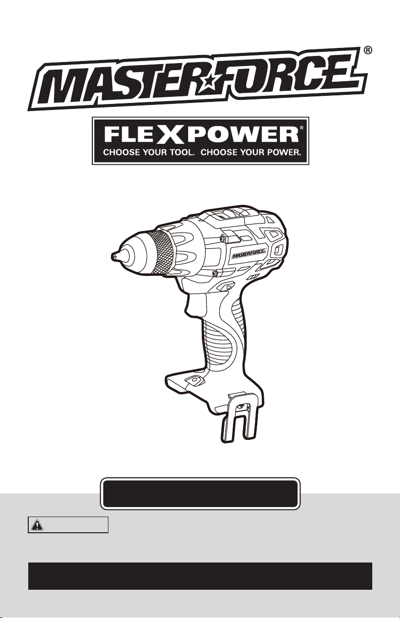
241-0462
1/2" BRUSHLESS DRILL/DRIVER
OPERATOR’S MANUAL
CAUTION:
To Reduce the Risk of Injury, User Must
Read and Understand the Operator’s Manual. Save These
Instructions For Future Reference.
For questions / comments, technical assistance or repair parts –
Please Call Toll Free: 1-866-917-4374. (M-F 8am – 6pm EST.)

TABLE OF CONTENTS
Safety Symbols ......................................................... Page 2
Safety Instructions ...................................................... Page 3
Overview/Specifications ................................................. Page 7
Assembly ............................................................. Page 7
Operation ............................................................. Page 8
Maintenance .......................................................... Page 14
Troubleshooting ....................................................... Page 15
Warranty .............................................................Page 16
Page 2
SAFETY SYMBOLS
Some of these following symbols may be used on this tool. Please study them and learn their
meaning. Proper interpretation of these symbols will allow you to operate the tool better and
more safely.
Symbol
Name
Designation / Explanation
V Volts Voltage
A Amperes Current
Hz Hertz Frequency (cycles per second)
W Watts Power
∿
Alternating current Type of current
�
Direct current Type or characteristic of current
n
o
No-load speed Rotational speed at no load
lbs Pounds Weight
Class II construction Double insulated construction
.../min Per minute
Revolutions, strokes, surface speed
orbits, etc., per minute
Wear safety goggles
WARNING:
The operation of any
power tool can result in foreign objects
being thrown into your eyes, which can
result in severe eye damage. Before
beginning power tool operation, always
wear safety goggles or safety glasses
with side shields and a full-face shield
when needed. We recommend a Wide
Vision Safety Mask for use over eye-
glasses or standard safety glasses with
side shields. Always use eye protection
which is marked to comply with
ANSI Z87.1.
WARNING:
To ensure safety and reliability, all repairs should be performed by a
qualified service technician.

Page 3
SAFETY INSTRUCTIONS
The purpose of safety symbols is to attract your attention to possible dangers. The safety
symbols and the explanations with them deserve your careful attention and understanding.
The symbol warnings do not, by themselves, eliminate any danger. The instructions and
warnings they give are no substitutes for proper accident prevention measures.
WARNING:
Be sure to read and understand all safety instructions in this manual,
including all safety alert symbols such as “DANGER,” ”WARNING,” and “CAUTION”
before using this tool. Failure to following all instructions listed below may result in
electric shock, fire, and/or serious personal injury.
SYMBOL MEANING
SAFETY ALERT SYMBOL: Indicates DANGER, WARNING, OR CAUTION.
May be used in conjunction with other symbols or pictographs.
DANGER:
Indicates an imminently hazardous situation, which, if not avoided,
will result in death or serious injury.
WARNING:
Indicates a potentially hazardous situation, which, if not avoided,
could result in death or serious injury.
CAUTION:
Indicates a potentially hazardous situation, which, if not avoided, could
result in minor or moderate injury.
NOTICE: (Without Safety Alert Symbol) Indicates a situation that may result in property
damage.
SAVE THESE INSTRUCTIONS!

Page 4
SAFETY INSTRUCTIONS
WARNING:
Read all safety
warnings and instructions!
Failure to follow the warnings and instructions
may result in electric shock, fire and / or serious
injury. Save all warnings and instructions for
future reference.
The term power tool in the warnings refers to
your mains-operated (corded) power tool or
battery-operated (cordless) power tool.
WARNING:
Risk of fire and
electric shock. Dry location use only. Do
not expose to rain. Risk of injury.
WORK AREA SAFETY
1. Keep the work area clean and well lit.
Cluttered or dark areas invite accidents.
2. Do not operate power tools in explosive
atmospheres, such as in the presence of
flammable liquids, gases or dust. Power
tools create sparks which may ignite the
dust or fumes.
3. Keep children and bystanders away
while operating a power tool. Distractions
can cause you to lose control.
ELECTRICAL SAFETY
1. Power tool plugs must match the
outlet. Never modify the plug in any way.
Do not use any adapter plugs with earthed
(grounded) power tools. Unmodified plugs
and matching outlets will reduce risk of
electric shock.
2. Avoid body contact with earthed
or grounded surfaces such as pipes,
radiators, ranges and refrigerators. There
is an increased risk of electric shock if your
body is earthed or grounded.
3. Do not expose power tools to rain or
wet conditions. Water entering a power tool
will increase the risk of electric shock.
4. Do not abuse the cord. Never use the
cord for carrying, pulling or unplugging the
power tool. Keep the cord away from heat,
oil, sharp edges or moving parts. Damaged
or entangled cords increase the risk of
electric shock.
5. When operating a power tool outdoors,
use an extension cord suitable for outdoor
use. Use of a cord suitable for outdoor use
reduces the risk of electric shock.
6. If operating a power tool in a damp
location is unavoidable, use a ground-fault
circuit interrupter (GFCI) protected supply.
Use of a GFCI reduces the risk of electric
shock.
PERSONAL SAFETY
1. Stay alert, watch what you are doing
and use common sense when operating a
power tool. Do not use the tool while tired
or under the influence of drugs, alcohol, or
medication. A moment of inattention while
operating power tools may result in serious
personal injury.
2. Use personal protective equipment.
Always wear eye protection. Protective
equipment such as a dust mask, non-skid
safety shoes, hard hat, or hearing protection,
used for appropriate conditions, will reduce
personal injuries.
3. Prevent unintentional starting. Ensure
that the switch is in the off-position before
connecting to a power source and/or
battery pack, picking up or carrying the tool.
Carrying power tools with your finger on the
switch or energizing power tools that have
the switch on invites accidents.
4. Remove any adjusting key or wrench
before turning the power tool on. A wrench
or a key left attached to a rotating part of the
power tool may result in personal injury.
5. Do not overreach. Keep proper footing
and balance at all times. This enables better
control of the power tool in unexpected
situations.

Page 5
SAFETY INSTRUCTIONS
6. Dress properly. Do not wear loose
clothing or jewelry. Keep your hair, clothing
and gloves away from moving parts. Loose
clothes, jewelry or long hair can be caught in
moving parts.
7. If devices are provided for the
connection of dust extraction and
collection facilities, ensure that these are
connected and properly used. Use of these
devices can reduce dust-related hazards.
USE AND CARE OF THE
POWER TOOLS
1. Do not force the power tool. Use the
correct power tool for your application. The
correct power tool will do the job better
and more safely at the rate for which it was
designed.
2. Do not use the power tool if the switch
does not turn it on and off. Any power tool
that cannot be controlled with the switch is
dangerous and must be repaired.
3. Disconnect the plug from the power
source and/or the battery pack from the
power tool before making any adjustments,
changing accessories, or storing power
tools. Such preventive safety measures
reduce the risk of starting the power tool
accidentally.
4. Store idle power tools out of the reach
of children and do not allow persons
unfamiliar with the power tool or these
instructions to operate the power tool.
Power tools are dangerous in the hands of
untrained users.
5. Maintain power tools. Check for
misalignment or binding of moving parts,
breakage of parts and any other condition
that may affect the power tool’s operation.
If damaged, have the power tool repaired
before use. Many accidents are caused by
poorly maintained power tools.
6. Keep cutting tools sharp and clean.
Properly maintained cutting tools with sharp
cutting edges are less likely to bind and are
easier to control.
7. Use the power tool, accessories,
tool bits, etc. in accordance with these
instructions, taking into account the
working conditions and the work to be
performed. Use of the power tool for
operations different from those intended
could result in a hazardous situation.
BATTERY TOOL USE
AND CARE
1. Recharge only with the charger
specified by the manufacturer. A charger
that is suitable for one type of battery pack
may create a risk of fire when used with
another battery pack.
2. Use power tools only with specifically
designated battery packs. Use of any other
battery packs may create a risk of injury and
fire.
3. When battery pack is not in use, keep
it away from other metal objects, like
paper clips, coins, keys, nails, screws or
other small metal objects that can make a
connection from one terminal to another.
Shorting the battery terminals together may
cause burns or a fire.
4. Under abusive conditions, liquid may
be ejected from the battery; avoid contact.
If contact accidentally occurs, flush with
water. If liquid contacts eyes, additionally
seek medical help. Liquid ejected from the
battery may cause irritation or burns.
SERVICE
1. Have your power tool serviced by a
qualified repair person using only identical
replacement parts. This will ensure that the
safety of the power tool is maintained.

Page 6
SAFETY INSTRUCTIONS
SPECIFIC SAFETY RULES FOR
BRUSHLESS DRILL/DRIVER
1. Know your drill/driver. Read operator’s
manual carefully. Learn the applications and
limitations, as well as the specific potential
hazards related to this tool. Following this
rule will reduce the risk of electric shock, fire
or serious injury.
2. Use auxiliary handle(s), if supplied with
the tool. Loss of control can cause personal
injury.
3. Hold power tools by insulated gripping
surfaces when performing an operation
where the cutting tool may contact hidden
wiring or its own cord. Contact with a “live”
wire will also make exposed metal parts of
the tool “live” and shock the operator.
4. Always wait until the machine has
come to a complete stop before placing it
down. The tool insert can jam and lead to
loss of control over the power tool.
5. Do not permit children to use the drill/
driver; it is not a toy.
6. Remove the battery pack from the
drill/driver before performing any routine
maintenance or cleaning.
7. Do not disassemble the drill/driver.
8. Do not place the drill/driver or battery
pack near fire or heat. They may explode.
9. Secure the workpiece. Clamping
devices or a vise will hold the workpiece in
place better than the hand.
10. Before performing any kind of work on
the tool (e. g. maintenance, bit change, etc.)
or when transporting and storing it, always
set the direction-of-rotation selector to
center off position. Unintentional activation
of the on/off switch may result in personal
injury.
11. Use protective gloves when removing
the bit from the tool, or allow the clamp
to cool down. The bit may be hot after
prolonged use.
12. Do not dispose of a worn out battery
pack by incinerating. Do not incinerate
the battery, even if it is severely damaged
or completely worn out. The battery may
explode in fire.
13. Do not operate the drill/driver or the
charger near flammable liquids or in a
gaseous or explosive environment. Internal
sparks may ignite fumes.
14. Keep the drill/driver dry, clean and free
from oil and grease. Always use a clean
cloth when cleaning. Never use brake fluids,
gasoline, petroleum-based products, or any
strong solvent to clean the drill/driver.
15. Save these instructions. Refer to them
frequently and use them to instruct others
who may use this tool. If you loan someone
this tool, also loan them these instructions.
DANGER:
People with electronic
devices, such as pacemakers, should
consult their physician(s) before using this
product. Operation of electrical equipment
in close proximity to a heart pacemaker
could cause interference or failure of the
pacemaker.
WARNING:
Some dust created by
power sanding, sawing, grinding, drilling
and other construction activities contains
chemicals known to the state of California
to cause cancer, birth defects or other
reproductive harm. Some examples of
these chemicals are:
• Lead from lead-based paints
• Crystalline silica from bricks and cement
and other masonry products, and
• Arsenic and chromium from chemically-
treated lumber.
Your risk from these exposures varies,
depending on how often you do this type
of work. To reduce your exposure to these
chemicals: work in a well ventilated area,
and work with approved safety equipment,
such as those dust masks that are specially
designed to filter out microscopic particles.
Page 7
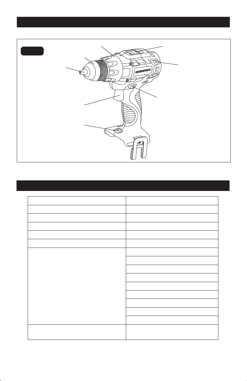
OVERVIEW
Chuck Jaws
Vents
Variable-speed
Trigger Switch
Direction-of-rotation
Selector (Forward/
Center-lock/Reverse)
LED Worklight
FIG. 1
SPECIFICATIONS
Motor 20Volt DC
Chuck 1/2” (13mm)
No Load Speeds 0-450/0-1750 RPM
Clutch 23+1positions
Torque 600 in.lbs
Weight (without battery) 2 lbs. 12 oz. (1.23 kg)
Compatible Batteries 252-8024
252-8028
252-8029
252-8030
252-8031
252-8032
252-8033
252-8034
252-8035
Battery Charger 252-8025, 252-8036, 252-8037,
252-8044
Keyless Chuck
Torque-adjustment Ring
Two-speed Gearbox Switch
Page 8
OPERATION
WARNING:
If any part is broken
or missing, DO NOT attempt to attach the
battery pack, or operate the tool until the
broken or missing part is replaced. Failure
to do so could result in possible serious
injury.
WARNING:
Do not attempt to
modify this tool or create accessories not
recommended for use with this tool. Any
such alteration or modification is misuse
and could result in a hazardous condition
leading to possible serious injury.
WARNING:
To prevent accidental
starting that could cause serious personal
injury, always remove the battery pack
from the drill/driver when you are
assembling parts, making adjustments,
installing or removing bits, or when it is
not in use.
ASSEMBLY
CONTENTS
Brushless drill/driver, belt clip, bit holder,
PH2 bit and instruction manual
UNPACKING
1. Carefully remove the tool and any
accessories from the carton. Make sure
that all items listed in the packing list are
included.
2. Inspect the tool carefully to make sure
that no breakage or damage occurred
during shipping.
3. Do not discard the packing material
until you have carefully inspected and
satisfactorily operated the tool.
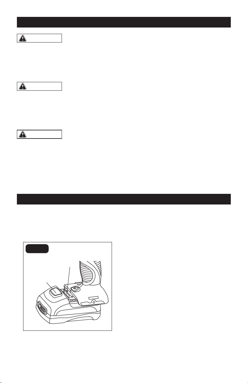
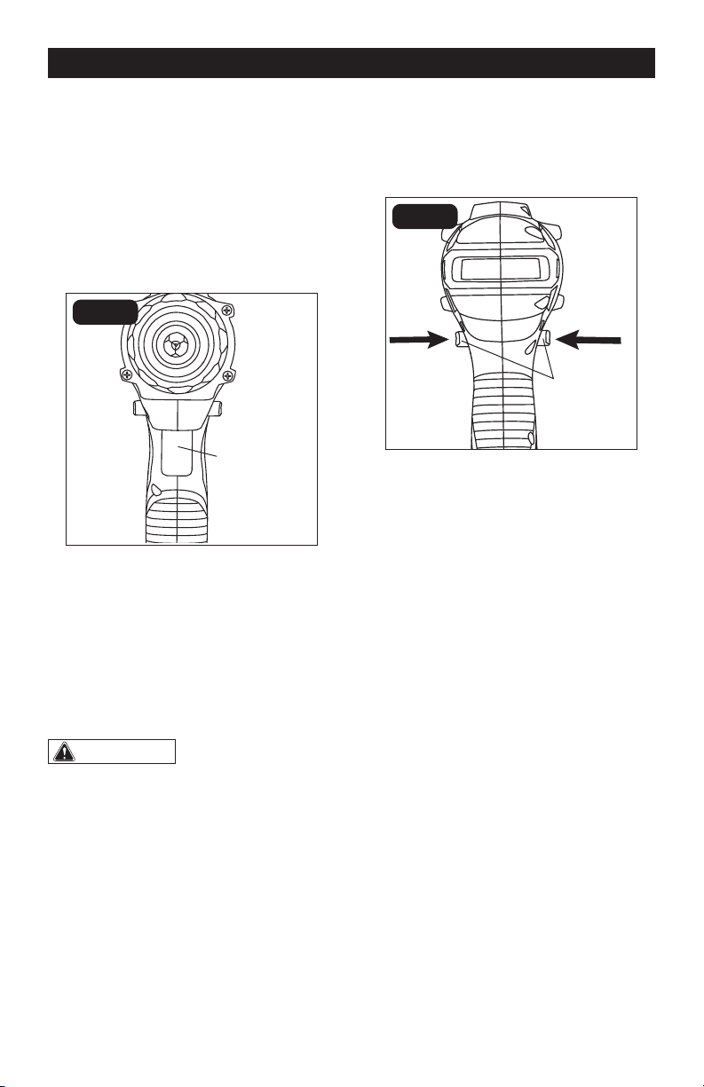
TO ATTACH BATTERY
PACK (FIG. 1)
FIG. 1
Battery-release
button
1. Lock the trigger switch on the drill/driver
by placing the direction-of-rotation
(forward/center-lock/reverse) selector in
the center position.
2. Align the raised ribs on the battery pack
with the grooves on the bottom of the
drill/driver, and then slide the drill/driver
forward to attach the battery pack to the
drill/driver.
NOTICE: Make sure that the latch on the
battery pack snaps into place and the bat-
tery pack is secured to the tool before
beginning operation. Improper assembly
of the battery pack can cause damage to
internal components.
TO DETACH BATTERY
PACK (FIG. 1)
1. Lock the trigger switch on the drill/driver
by placing the direction-of-rotation
(forward/center-lock/reverse) selector in
the center position.
Latch
Page 9
2. Depress the battery-release button,
located on the front of the battery pack,
to release the battery pack.
3. Pull the battery pack and remove it from
the tool.
VARIABLE-SPEED TRIGGER
SWITCH (FIG. 2)
FIG. 2
1. To turn the drill/driver ON, press the
trigger switch.
2. To turn the drill/driver OFF, release the
trigger switch.
3. The variable-speed trigger switch
delivers higher speed with increased
trigger pressure and lower speed with
decreased trigger pressure.
WARNING:
Allow the motor to
come to a complete stop before setting
the drill/driver down.
DIRECTION -OF-ROTATION
SELECTOR (FORWARD/CENTER-
LOCK/REVERSE) (FIG. 3)
FIG. 3
Reverse
The direction of bit rotation is reversible and
is controlled by a selector located above the
trigger switch. With the drill/driver held in
normal operating position:
1. Position the direction-of-rotation
selector to the right of the tool for
reverse rotation.
2. Position the direction-of-rotation
selector to the left of the tool for forward
rotation.
3. Setting the direction-of-rotation selector
in the OFF (center-lock) position helps
reduce the possibility of accidental
starting when not in use.
NOTICE: To prevent gear damage, always
allow the drill/driver to come to a complete
stop before changing the direction of rota-
tion.
NOTICE: The drill/driver will not run unless
the direction-of-rotation selector is en-
gaged fully to the left or right.
OPERATION
Variable-speed
trigger switch
Forward
Direction-
of-rotation
selector
Page 10
OPERATION
ELECTRIC BRAKE
To stop the drill/driver, release the trigger
switch and allow the chuck to come to a
complete stop. The electric brake quickly
stops the chuck from rotating. This feature
engages automatically when you release the
trigger switch.
TWO-SPEED
GEARBOX (FIG. 4)
LO
HI
FIG. 4
The drill/driver has a two-speed gearbox for
drilling or driving at low or high speeds. A
slide switch is located on the top of the drill/
driver to select either low or high speed. The
required speed is adjusted depending on
the material and the working conditions.
Use low speed for high power and torque
applications and high speed for fast drilling
or driving applications.
When using drill/driver in the low speed
range, the speed will decrease and the drill/
driver will have more power and torque.
Use low speed for starting holes without
a center punch, drilling metals or plastic,
drilling ceramics, or in applications requiring
a higher torque.
High speed is better for drilling wood and
wood composites.
NOTICE: Avoid running the drill/driver at
high speed for extended periods of time.
Running at high speed under constant us-
age may cause the drill/driver to become
overheated.
CAUTION:
Never adjust the speed
while the tool is running. Failure to obey
this caution could result in serious damage
to the drill/driver.
NOTICE: Make sure that the two-speed
gearbox switch is fully adjusted at the front
or the back position.
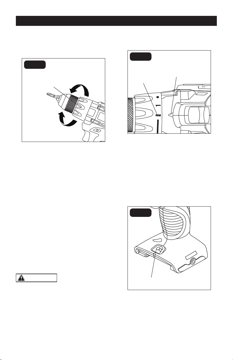
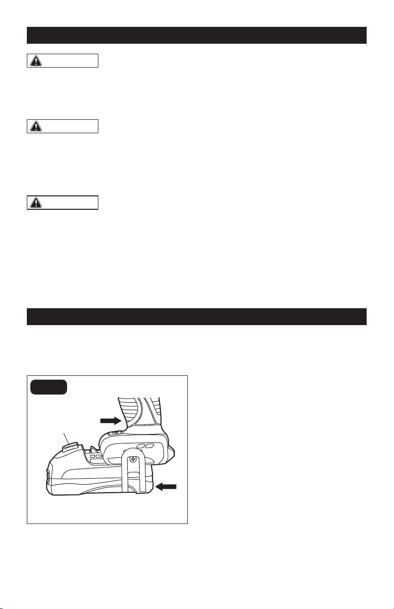
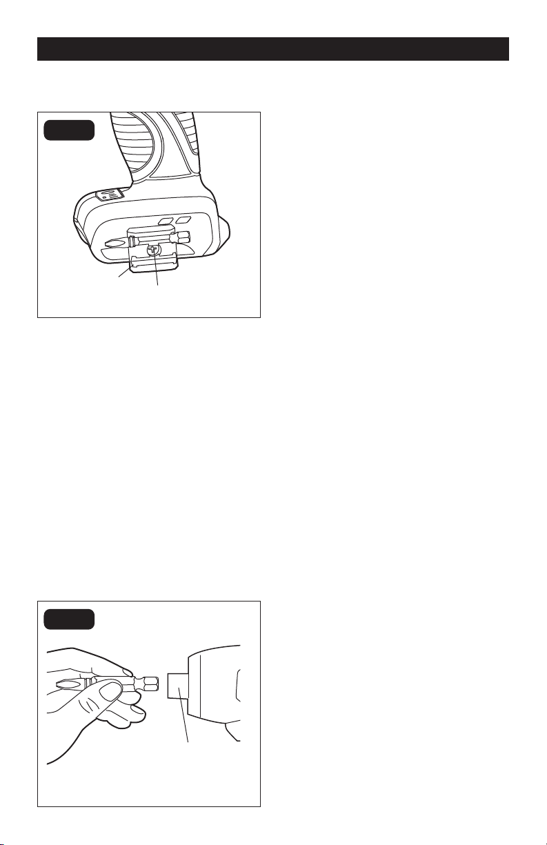
KEYLESS CHUCK (FIG. 5)
FIG. 5
The drill/driver has a keyless chuck to
tighten or release bits in the chuck jaws. The
arrows on the chuck indicate the direction in
which to rotate the chuck in order to GRIP
(tighten) or OPEN (release) the chuck jaws
on the bit.
WARNING:
Do not hold the chuck
with one hand and use the power of the
drill/driver to tighten the chuck jaws on
the drill bit. The chuck could slip in your
hand, or your hand could slip and come
in contact with the rotating bit. This could
cause an accident resulting in serious
personal injury.
GRIP (tighten)
OPEN
(release)
Keyless chuck
Chuck jaws
Page 11
OPERATION
ADJUSTABLE-TORQUE
CLUTCH (FIG. 6)
FIG. 6
To increase torque
The higher the torque drill setting, the more
force the drill/driver produces to turn an
object in either low or high rotation speed.
When using the drill/driver for different
driving applications, increase or decrease
the torque in order to help prevent damage
to screw heads, threads, workpiece, etc.
Adjust the torque by rotating the torque-
adjustment ring. The proper setting depends
on the job and the type of bit, fastener, and
material you will be using.
In general, use greater torque for larger
screws. If the torque is too high, the screws
may be damaged or broken.
For delicate operations, such as removing
a partially stripped screw, use a low torque
setting. For operations such as drilling into
hardwood, use a higher torque setting.
CAUTION:
Do not change the
torque setting when the tool is running.
DRILL MODE (FIG. 7)
FIG. 7
Drill icon
Torque indicator
Select the drill mode for drilling and other
heavy-duty applications.
To select drill mode, rotate the torque-
adjustment ring until the drill icon aligns with
the torque indicator.
LED WORKLIGHT (FIG. 8)
FIG. 8
LED worklight
The LED worklight, located on the base
of the drill/driver, will illuminate when the
trigger switch is depressed before the drill/
driver is running. This provides additional
light on the surface of the workpiece. The
light will automatically turn off within 10
seconds after releasing the trigger.
To decrease torque
Torque-adjustment
ring
Page 12
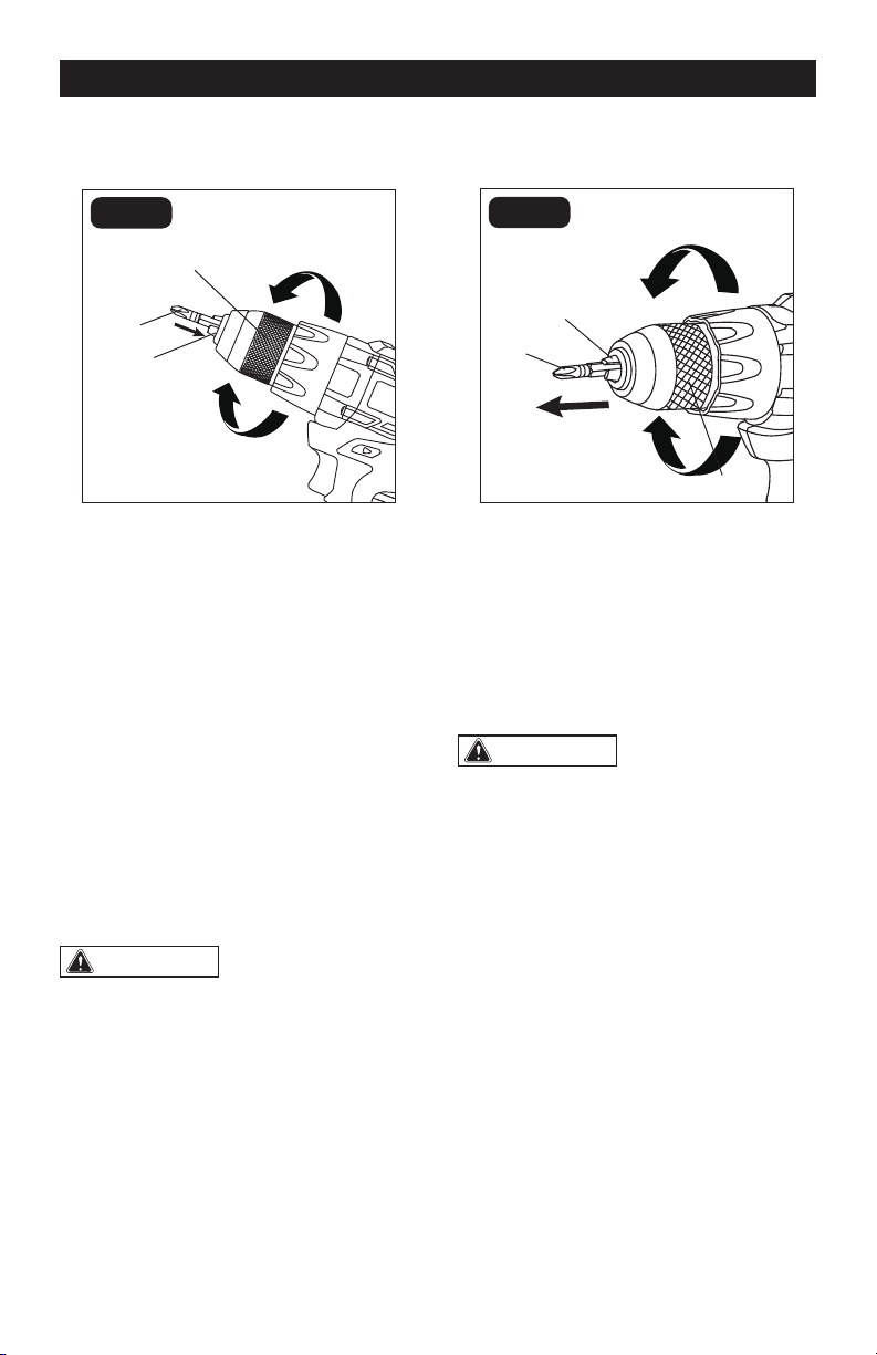
INSTALLING BITS (FIG. 9)
FIG. 9
Bit
1. Remove the battery pack from the drill/
driver.
2. Open the chuck jaws until the opening is
slightly larger than the bit you intend to
use, and raise the front of the drill/driver
slightly to keep the bit from falling out of
the chuck jaws.
3. Insert the bit into the chuck.
4. Rotate the chuck in the direction of the
arrow marked GRIP to close the chuck
jaws.
NOTICE: Do not use a wrench to tighten or
loosen the chuck jaws.
5. Tighten the chuck jaws securely on the
bit.
WARNING:
Make sure to insert
the bit straight into the chuck jaws. Do
not insert the bit into the chuck jaws at an
angle and then tighten. This could cause
the bit to be thrown from the drill/driver,
resulting in possibly serious personal
injury or damage to the chuck.
OPERATION
REMOVING BITS (FIG. 10)
FIG. 10
1. Remove the battery pack from the drill/
driver.
2. Open the chuck jaws.
3. Rotate the chuck in the direction of
the arrow marked OPEN to loosen the
chuck jaws.
4. Remove the bit.
WARNING:
Use protective gloves
when removing the bit from the tool, or
first allow the bit to cool down. The bit
may be hot after prolonged use.
GRIP (tighten) GRIP
(tighten)
OPEN
(release)
OPEN
(release)
Keyless chuck
Keyless chuck
Chuck jaws
Chuck jaws
Bit
Page 13
OPERATION
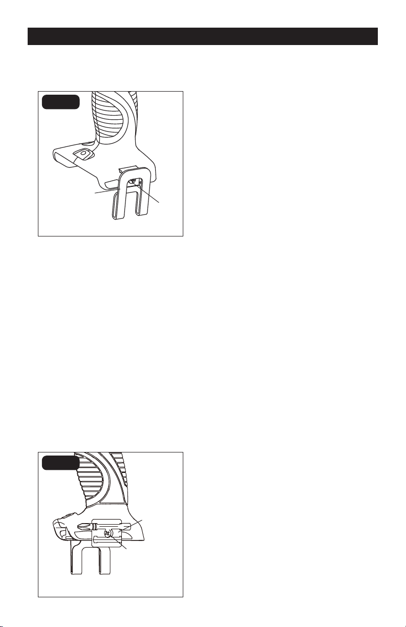
INSTALLING AND REMOVING
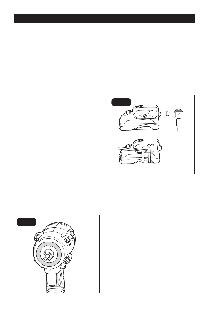
THE BELT CLIP (FIG.11)
FIG. 11
To install the belt clip:
1. Align the rib of the clip with the hole on
the base of the drill.
2. Insert the screw and tighten the screw
securely with a screwdriver. The belt clip
can be positioned on either side of the
tool.
To remove the belt clip:
1. Use a screwdriver to loosen the screw
that attaches the belt clip to the drill.
2. Remove the screw and the belt clip.
INSTALLING AND REMOVING
THE BIT HOLDER (FIG.12)
FIG. 12
Bit holder
To install the bit holder:
1. Align the rib of the bit holder the hole on
the base of the drill.
2. Insert the screw (included) and tighten
the screw securely with a screwdriver.
The bit holder can be positioned on
either side of the tool.
To remove the bit holder:
1. Use a screwdriver to loosen the screw
that attaches the bit holder to the drill.
2. Remove the screw and the bit holder.
DRILLING
1. Check that the direction-of-rotation
selector is at the forward setting.
2. Secure the material to be drilled in a vise
or with clamps to keep it from turning as
the drill bit (available separately) rotates.
3. Hold the drill/driver firmly, and place the
bit at the point to be drilled.
4. Depress the trigger switch to start the
drill/driver.
5. Move the drill bit into the workpiece,
applying only enough pressure to keep
the bit drilling. Do not force the drill or
apply side pressure to elongate a hole.
Let the tool do the work.
6. When drilling hard, smooth surfaces,
use a center punch to mark the desired
location of the hole. This will prevent the
drill bit from slipping off-center as the
hole is started.
7. When drilling metals, use light oil on
the drill bit to keep it from overheating.
The oil will prolong the life of the bit and
increase the drilling action.
8. If the bit jams in the workpiece or if the
drill stalls, stop the tool immediately.
Remove the bit from the workpiece and
determine the reason for jamming.
Screw
Screw
Belt clip

Page 14
OPERATION
DRILLING IN WOOD
For maximum performance, use wood-
boring brad-point drill bits (available
separately) or brad-point bits (available
separately) for wood drilling.
1. When drilling “through” holes, place a
block of wood behind the workpiece to
prevent ragged or splintered edges on
the back side of the hole.
2. Begin drilling at a very low speed to
prevent the bit from slipping off the
starting point.
3. Increase speed as the drill bit bites into
the material.
DRILLING IN METAL
For maximum performance, use high speed
steel bits (available separately) for metal or
steel drilling.
1. When drilling metals, use light oil on
the drill bit to keep it from overheating.
The oil will prolong the life of the bit and
increase the drilling action.
2. Begin drilling at a very low speed to
prevent the bit from slipping off the
starting point.
3. Maintain a speed and a pressure that
allow cutting without overheating the
bit. Applying too much pressure will:
• Overheat the drill/driver
• Wear the bearings
• Bend or burn bits
• Produce off-center or irregularly shaped
holes
WARNING:
To avoid serious
personal injury, always remove the battery
pack from the tool when cleaning or
performing any maintenance. Contact a
qualified service technician for all repairs.
WARNING:
When servicing, use
only identical replacement parts. Use
of any other parts may create a hazard
or cause product damage. For more
information, call the toll-free helpline, at
1-866-917-4374.
WARNING:
Avoid using solvents
when cleaning plastic parts. Most plastics
are susceptible to damage from various
types of commercial solvents and may be
damaged by their use. Use a clean cloth
to remove dirt, dust, oil, grease, etc.
WARNING:
Using compressed
air may be the most effective cleaning
method. Always wear safety goggles
when cleaning tools with compressed air.
Page 15
REMOVING THE CHUCK (FIG. 13)
FIG. 13
Chuck screw
1. Remove the battery pack from the drill/
driver.
2. Open the chuck jaws.
3. Use a Philips screwdriver (available
separately) to remove the chuck screw
by turning it in a clockwise direction.
NOTICE: The chuck screw has left-handed
threads.
4. Insert a 3/8” hex key (available
separately) into the chuck and securely
tighten the chuck jaws onto the hex
key. Tap the hex key sharply with
a mallet (available separately) in a
counterclockwise direction. This will
loosen the chuck on the spindle. It can
now be unscrewed by hand.
TO RETIGHTEN THE CHUCK
1. Remove the battery pack from the drill/
driver.
2. Open the chuck jaws.
3. Insert a 3/8” hex key (available
separately) into the chuck and securely
tighten the chuck jaws onto the hex key.
Tap the hex key sharply with a mallet
(available separately) in a clockwise
direction. This will tighten the chuck
onto the spindle.
4. Open the chuck jaws and remove the
hex key.
5. Use a Philips screwdriver (available
separately) to turn the chuck screw
counterclockwise to tighten it.
MAINTENANCE

Page 16
TROUBLESHOOTING
PROBLEM CAUSE SOLUTION
The drill/driver does not work Battery is depleted Charge the battery
Bit cannot be installed
Chuck jaws are not open Open the chuck jaws
The bit does not fit the
chuck jaw.
Use an appropriate bit with a
shank no larger than ½ in.
Motor is overheating
The cooling vents may be
obstructed.
Clean, clear the vents. Do
not cover the vents with your
hand during operation

Page 17
NOTES

SAVE YOUR RECEIPTS
THIS WARRANTY IS VOID WITHOUT THEM
1/2" BRUSHLESS DRILL/DRIVER
WARRANTY
90-DAY MONEY BACK GUARANTEE:
This MASTERFORCE® brand power tool carries our 90-DAY Money Back
Guarantee. If you are not completely satisfied with your MASTERFORCE® brand
power tool for any reason within ninety (90) days from the date of purchase, return
the tool with your original receipt to any MENARDS® retail store, and we will provide
you a refund – no questions asked.
3-YEAR LIMITED WARRANTY:
This MASTERFORCE® brand power tool carries our famous No Hassle 3-Year Limited
Warranty to the original purchaser. If, during normal use, this MASTERFORCE® power
tool breaks or fails due to a defect in material or workmanship within three (3) years
from the date of original purchase, simply bring this tool with the original sales receipt
back to your nearest MENARDS® retail store. At its discretion, MASTERFORCE®
agrees to have the tool or any defective part(s) repaired or replaced with the same or
similar MASTERFORCE® product or part free of charge, within the stated warranty
period, when returned by the original purchaser with original sales receipt. Not
withstanding the foregoing, this limited warranty does not cover any damage that
has resulted from abuse or misuse of the Merchandise. This warranty: (1) excludes
expendable parts including but not limited to blades, brushes, belts, bits, light bulbs,
and/or batteries; (2) shall be void if this tool is used for commercial and/or rental
purposes; and (3) does not cover any losses, injuries to persons/property or costs. This
warranty does give you specific legal rights and you may have other rights, which vary
from state to state. Be careful, tools are dangerous if improperly used or maintained.
Seller’s employees are not qualified to advise you on the use of this Merchandise.
Any oral representation(s) made will not be binding on seller or its employees. The
rights under this limited warranty are to the original purchaser of the Merchandise
and may not be transferred to any subsequent owner. This limited warranty is in lieu
of all warranties, expressed or implied including warranties or merchantability and
fitness for a particular purpose. Seller shall not be liable for any special, incidental, or
consequential damages. The sole exclusive remedy against the seller will be for the
replacement of any defects as provided herein, as long as the seller is willing or able
to replace this product or is willing to refund the purchase price as provided above.
For insurance purposes, seller is not allowed to demonstrate any of these power tools
for you.
For questions / comments, technical assistance or repair parts – Please Call Toll
Free at: 1-866-917-4374. (M-F 8am – 6pm)

06/2015
© 2015 Menard, Inc., Eau Claire, WI 54703
241-0435
1/4” Impact Driver
OPERATOR’S MANUAL
CAUTION:
To Reduce the Risk of Injury, User Must
Read and Understand the Operator’s Manual. Save These
Instructions For Future Reference.
For questions / comments, technical assistance or repair parts –
Please Call Toll Free: 1-866-917-4374 (M-F 8:30am-5:00pm EST).

TABLE OF CONTENTS
Safety Symbols ......................................................... Page 2
Safety Instructions ...................................................... Page 3
Overview/Specifications ................................................. Page 7
Assembly ............................................................. Page 8
Operation ............................................................ Page 11
Maintenance .......................................................... Page 12
Troubleshooting ....................................................... Page 13
Warranty ............................................................. Page 14
Page 2
SAFETY SYMBOLS
Some of these following symbols may be used on this tool. Please study them and learn their
meaning. Proper interpretation of these symbols will allow you to operate the tool better and
more safely.
Symbol
Name
Designation / Explanation
V Volts Voltage
A Amperes Current
Hz Hertz Frequency (cycles per second)
W Watts Power
∿
Alternating current Type of current
�
Direct current Type or characteristic of current
n
o
No-load speed Rotational speed at no load
Class II construction Double insulated construction
.../min Per minute
Revolutions, strokes, surface speed
orbits, etc., per minute
Wear safety goggles
WARNING:
The operation of any
power tool can result in foreign objects
being thrown into your eyes, which can
result in severe eye damage. Before
beginning power tool operation, always
wear safety goggles or safety glasses
with side shields and a full-face shield
when needed. We recommend a Wide
Vision Safety Mask for use over eye-
glasses or standard safety glasses with
side shields. Always use eye protection
which is marked to comply with
ANSI Z87.1.
WARNING:
To ensure safety and reliability, all repairs should be performed by a
qualified service technician.
Page 3
SAFETY INSTRUCTIONS
The purpose of safety symbols is to attract your attention to possible dangers. The safety
symbols, and the explanations with them, deserve your careful attention and understand-
ing. The symbol warnings do not, by themselves, eliminate any danger. The instructions and
warnings they give are no substitutes for proper accident prevention measures.
WARNING:
Be sure to read and understand all safety instructions in this manual,
including all safety alert symbols such as “DANGER”, “WARNING” and “CAUTION” before
using this tool. Failure to following all instructions listed below may result in electric
shock, fire, and/or serious personal injury.
SYMBOL MEANING
SAFETY ALERT SYMBOL: Indicates DANGER, WARNING, OR CAUTION.
May be used in conjunction with other symbols or pictographs.
DANGER:
Indicates an imminently hazardous situation, which, if not avoided, will
result in death or serious injury.
WARNING:
Indicates a potentially hazardous situation, which, if not avoided,
could result in death or serious injury.
CAUTION:
Indicates a potentially hazardous situation, which, if not avoided, could
result in minor or moderate injury.
NOTICE: (Without Safety Alert Symbol) Indicates a situation that may result in property
damage.
SAVE THESE INSTRUCTIONS!

Page 4
SAFETY INSTRUCTIONS
GENERAL POWER TOOL SAFETY
WARNINGS
WARNING:
Read all safety
warnings, instruction, illustrations and
specifications provided with this power
tool.
Failure to follow all instructions listed below
may result in electric shock, fire and/or seri-
ous injury.
Save all warnings and instructions for future
reference.
The term “power tool” in the warnings refers
to your mains-operated (corded) power tool
or battery-operated (cordless) power tool.
WORK AREA SAFETY
a) Keep work area clean and well lit.
Cluttered or dark areas invite accidents.
b) Do not operate power tools in explosive
atmospheres, such as in the presence of
flammable liquids, gases or dust. Power
tools create sparks which may ignite the
dust or fumes.
c) Keep children and bystanders away
while operating a power tool. Distractions
can cause you to lose control.
ELECTRICAL SAFETY
a) Power tool plugs must match the
outlet. Never modify the plug in any way.
Do not use any adapter plugs with earthed
(grounded) power tools. Unmodified plugs
and matching outlets will reduce risk of
electric shock.
b) Avoid body contact with earthed
or grounded surfaces, such as pipes,
radiators, ranges and refrigerators. There
is an increased risk of electric shock if your
body is earthed or grounded.
c) Do not expose power tools to rain or
wet conditions. Water entering a power
tool will increase the risk of electric shock.
d) Do not abuse the cord. Never use the
cord for carrying, pulling or unplugging
the power tool. Keep cord away from
heat, oil, sharp edges or moving parts.
Damaged or entangled cords increase the
risk of electric shock.
e) When operating a power tool outdoors,
use an extension cord suitable for outdoor
use. Use of a cord suitable for outdoor use
reduces the risk of electric shock.
f) If operating a power tool in a damp
location is unavoidable, use a ground fault
circuit interrupter (GFCI) protected supply.
Use of an GFCI reduces the risk of electric
shock.
PERSONAL SAFETY
a) Stay alert, watch what you are doing
and use common sense when operating a
power tool. Do not use a power tool while
you are tired or under the influence of
drugs, alcohol or medication. A moment of
inattention while operating power tools may
result in serious personal injury.
b) Use personal protective equipment.
Always wear eye protection. Protective
equipment such as a dust mask, non-skid
safety shoes, hard hat or hearing protection
used for appropriate conditions will reduce
personal injuries.
c) Prevent unintentional starting. Ensure
the switch is in the off-position before
connecting to power source and/or battery
pack, picking up or carrying the tool.
Carrying power tools with your finger on the
switch or energizing power tools that have
the switch on invites accidents.
d) Remove any adjusting key or wrench
before turning the power tool on. A wrench
or a key left attached to a rotating part of
the power tool may result in personal injury.
e) Do not overreach. Keep proper
footing and balance at all times. This
enables better control of the power tool in
unexpected situations.
f) Dress properly. Do not wear loose
clothing or jewelry. Keep your hair and

Page 5
SAFETY INSTRUCTIONS
clothing away from moving parts. Loose
clothes, jewelry or long hair can be caught
in moving parts.
g) If devices are provided for the
connection of dust extraction and
collection facilities, ensure these are
connected and properly used. Use of dust
collection can reduce dust-related hazards.
h) Do not let familiarity gained from
frequent use of tools allow you to become
complacent and ignore tool safety
principles. A careless action can cause
severe injury within a fraction of a second.
POWER TOOL USE AND CARE
a) Do not force the power tool. Use the
correct power tool for your application. The
correct power tool will do the job better and
safer at the rate for which it was designed.
b) Do not use the power tool if the switch
does not turn it on and off. Any power tool
that cannot be controlled with the switch is
dangerous and must be repaired.
c) Disconnect the plug from the power
source and/or remove the battery pack,
if detachable, from the power tool before
making any adjustments, changing
accessories, or storing power tools. Such
preventive safety measures reduce the risk
of starting the power tool accidentally.
d) Store idle power tools out of the reach
of children and do not allow persons
unfamiliar with the power tool or these
instructions to operate the power tool.
Power tools are dangerous in the hands of
untrained users.
e) Maintain power tools and accessories.
Check for misalignment or binding of
moving parts, breakage of parts and
any other condition that may affect the
power tool’s operation. If damaged, have
the power tool repaired before use. Many
accidents are caused by poorly maintained
power tools.
f) Keep cutting tools sharp and clean.
Properly maintained cutting tools with sharp
cutting edges are less likely to bind and are
easier to control.
g) Use the power tool, accessories
and tool bits etc. in accordance with
these instructions, taking into account
the working conditions and the work to
be performed. Use of the power tool for
operations different from those intended
could result in a hazardous situation.
h) Keep handles and grasping surfaces dry,
clean and free from oil and grease. Slippery
handles and grasping surfaces do not allow
for safe handling and control of the tool in
unexpected situations.
SERVICE
a) Have your power tool serviced by a
qualified repair person using only identical
replacement parts. This will ensure that the
safety of the power tool is maintained.
SPECIFIC SAFETY WARNINGS
a) Hold power tools by insulated gripping
surfaces when performing an operation
where the cutting tool may contact hidden
wiring. Contact with a” live” wire will make
exposed metal parts of the tool live and
shock the operator.
b) Take protective measures when
dust can develop during working that
is harmful to one’s health, combustible
or explosive. Example: Some dusts are
regarded as carcinogenic. Wear a dust
mask and work with dust/chip extraction
when connectable.
c) Secure the workpiece. A workpiece
clamped with clamping devices or in a vice
is held more secure than by hand.
d) To reduce the risk of electric shock or
damage to the charger and battery, use
only the batteries and charger listed.

Page 6
SAFETY INSTRUCTIONS
Battery pack Charger
252-8027
252-8029
252-8030
252-8031
252-8034
252-8035
252-8003
252-8005
252-8007
252-8025
252-8026
252-8037
WARNING:
Some dust created by
power sanding, sawing, grinding, drilling
and other construction activities contains
chemicals known to the state of California
to cause cancer, birth defects or other
reproductive harm. Some examples of
these chemicals are:
• Lead from lead-based paints
• Crystalline silica from bricks and cement
and other masonry products, and
• Arsenic and chromium from chemically-
treated lumber.
Your risk from these exposures varies,
depending on how often you do this type
of work. To reduce your exposure to these
chemicals: work in a well ventilated area,
and work with approved safety equipment,
such as those dust masks that are specially
designed to filter out microscopic particles.
Page 7
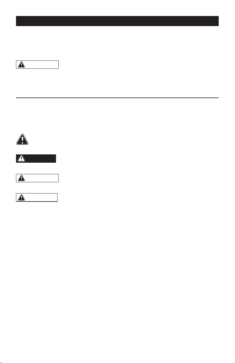
OVERVIEW
SPECIFICATIONS
No-load Speed I: 0-1,100 RPM
II: 0-1,900 RPM
III: 0-2,800 RPM
Impact Rate I: 0-1,200 BPM
II: 0-2,350 BPM
III: 0-3,300 BPM
Torque I: 770 in.lb
II: 1,240 in.lb
III: 1,700 in.lb
Driver 1/4” Hex
Weight 2 lb. 14 oz (1.3 kg)
LED Worklight Ring
Mode-selector
Trigger Switch
Chuck
Direction-of-rotation
Selector
Belt Clip
Page 8
ASSEMBLY
WARNING:
If any part is broken or
missing, DO NOT attach the battery pack
or operate the tool until the broken or
missing part is replaced. Failure to do so
could result in possible serious injury.
WARNING:
Do not attempt to
modify this tool or create accessories not
recommended for use with this tool. Any
such alteration or modification is misuse
and could result in a hazardous condition
leading to possible serious injury.
WARNING:
Your tool should
never be connected to the battery pack
when you are assembling parts, making
adjustments, installing or removing
bits, cleaning, or when it is not in use.
Disconnecting the tool will prevent
accidental starting, which could cause
serious personal injury.
ASSEMBLY
CONTENTS
Cordless impact driver, bit holder, belt clip,bit
and instruction manual.
UNPACKING
1. Carefully remove the tool and any
accessories from the carton. Make sure
that all items listed in the packing list are
included.
2. Inspect the tool carefully to make sure
that no breakage or damage occurred
during shipping.
3. Do not discard the packing material
until you have carefully inspected and
satisfactorily operated the blower.
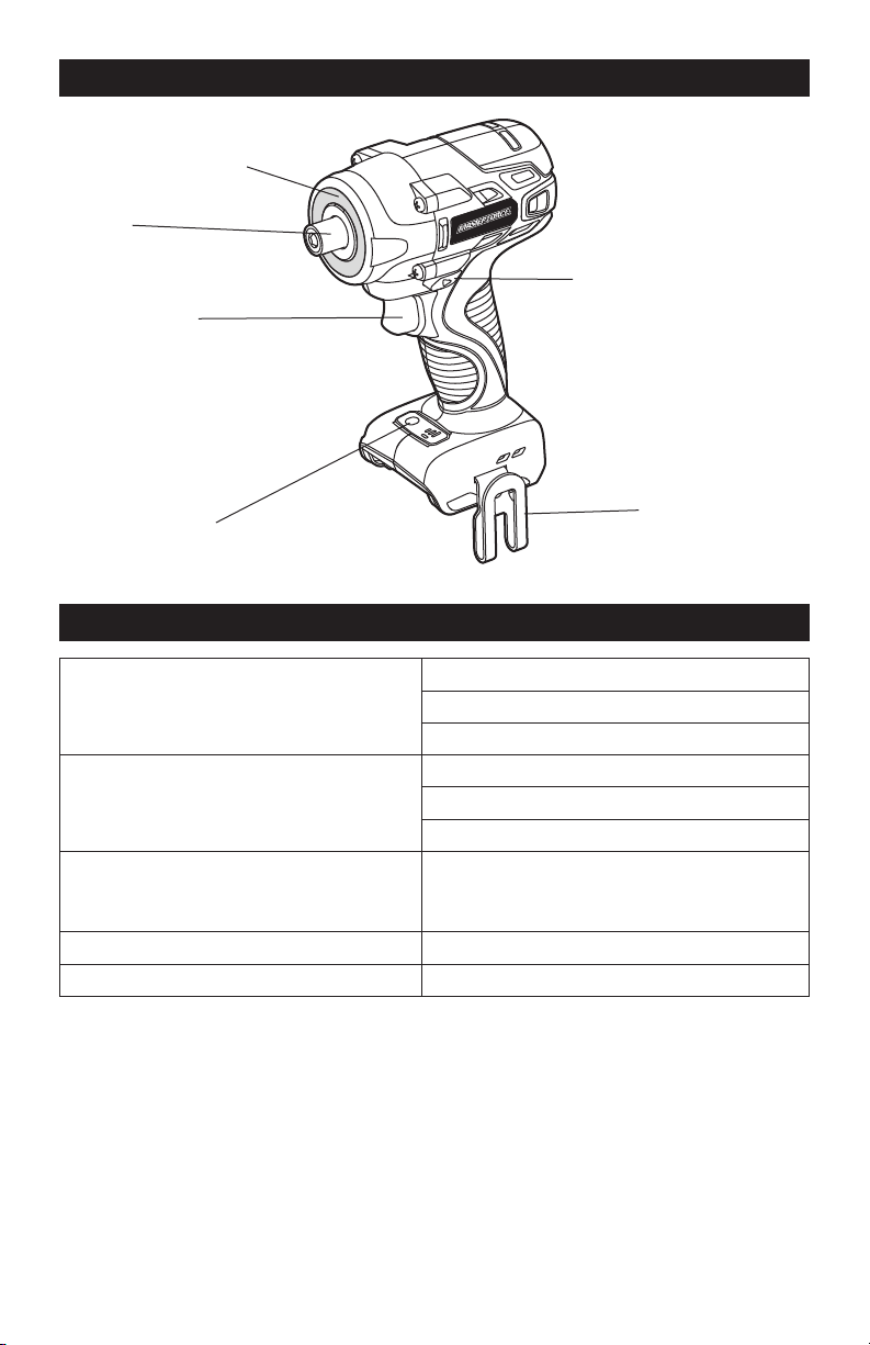
TO ATTACH BATTERY PACK
(FIG. 1)
1. Make sure that the tool is switched off.
2. Align the raised rib on the battery pack
with the grooves on the bottom of the
impact driver, and then slide the battery
pack onto the tool.
NOTICE: Make sure that the latch on the
battery pack snaps into place and the bat-
tery pack is secured to the tool before op-
eration.
TO DETACH BATTERY PACK
(FIG. 1)
1. Make sure that the tool is switched off.
2. Depress the battery-release button
located on the front of the battery pack
to release the battery pack.
3. Pull the battery pack out and remove it
from the tool.
Attach
Battery-release
Button
Detach
FIG. 1
Page 9
TRIGGER SWITCH (FIG.2)
To turn the impact driver on, depress the
trigger switch.
To turn it off, release the trigger switch.
VARIABLE SPEED
The variable-speed trigger switch delivers
higher speed with increased trigger pressure
and lower speed with decreased trigger
pressure.
DIRECTION-OF-ROTATION SE-
LECTOR (FORWARD/CENTER-
LOCK/REVERSE) (FIG.3)
The direction of rotation is reversible and is
controlled by a selector located above the
trigger switch. With the impact driver held
in normal operating position: position the
direction-of-rotation selector to the left of
the tool for forward rotation; position the
direction-of-rotation selector to the right
of the tool for reverse rotation. Setting the
switch in the OFF (center-lock) position
helps to reduce the possibility of accidental
starting when not in use.
NOTICE: To prevent gear damage, always
allow the impact driver to come to a com-
plete stop before changing the direction of
rotation.
NOTICE: The impact driver will not run un-
less the direction of the rotation selector is
engaged fully to the left or right.
MODE SELECTOR (FIG.4)
NOTICE: The impact driver is designed
with 3-speed and auto-stop functions;
these functions are available only when the
tool is operating in forward rotation.
NOTICE: The mode can only be changed
when the mode-indicator light is on. The
mode-indicator light will be off automati-
cally in about one minute.
1. Attach the battery pack to the impact
driver.
ASSEMBLY
Direction-of-
rotation Selector
Trigger Switch
FIG. 2
Reverse
Forward
FIG. 3
L
AUTOSTOP
H
Mode Selector
Mode Indicator
Auto-stop
Indicator
FIG. 4
Page 10
ASSEMBLY
2. Position the direction-of-rotation
selector to the left of the tool for forward
rotation, and press the trigger switch to
turn on the mode-indicator light.
3. Press the mode selector to change the
speed: press once for low, press twice
for medium, and press a third time for
high.
4. To make the Auto-stop function
available, press and hold the mode
selector for three seconds: the auto-
stop indicator will shine. When a bolt/
nut is sufficiently tightened, the tool
will automatically stop the impact
and rotation after approximately one
second.
5. To turn off the auto-stop function, press
and hold the mode selector for three
seconds again. The auto-stop indicator
is will turn off.
ELECTRIC BRAKE
The impact driver is equipped with an
electric brake. When the trigger switch
is released, the electric brake engages
automatically to quickly stop the rotation.
LED WORKLIGHT RING (FIG.5)
The LED worklight rings, located around
the shaft of the impact driver, will illuminate
when the trigger switch is depressed. This
provides additional light on the surface of the
workpiece for operation in lower-light areas.
The light will automatically turn off within 10
seconds after the trigger is released.
INSTALLING THE BELT CLIP
(FIG.6)
1. Remove the battery from the tool.
2. Align the rib of the belt clip with the hole
on the base of the driver.
3. Insert the screw and securely tighten
the screw with a screwdriver.
REMOVING THE BELT CLIP
1. Remove the battery from the tool.
2. Use a screwdriver to loosen the screw
that attaches the belt clip to the driver.
3. Remove the screw and the belt clip.
FIG. 5
Belt Clip
FIG. 6
Page 11
OPERATION
TO INSTALL THE BIT HOLDER
(FIG.7):
1. Remove the battery from the tool.
2. Align the rib of the bit holder with the
hole in the base of the impact driver.
3. Insert the screw (included) and securely
tighten the screw with a screwdriver
(not included). The bit holder can be
positioned on either side of the tool.
To remove the bit holder:
1. Remove the battery from the tool.
2. Use a screwdriver to loosen the screw
that attaches the bit holder to the
impact driver.
3. Remove the screw and the bit holder.
INSTALLING BITS (FIG.8)
1. Lock the trigger switch on the impact
driver by placing the direction-of-
rotation selector in the center position.
2. Insert the bit into the chuck. You will
hear a “click” to indicate that the bit is
securely installed in place.
3. Pull on the bit to check if it installed
securely.
REMOVING BITS
1. Lock the trigger switch on the impact
driver by placing the direction-of-
rotation selector in the center position.
2. Pull the sleeve towards the front of the
tool.
3. The bit should pop out from the chuck
automatically, if not, simply pull out the
bit.
TIGHTENING AND LOOSENING
SCREWS
1. Install the correct bit.
2. Apply just enough pressure to keep the
bit engaged on the screw.
3. Apply minimal pressure to the trigger
switch initially. Increase the speed only
when full control can be maintained.
TIGHTENING AND LOOSENING
NUTS AND BOLTS
Variable speed control must be used with
caution for driving nuts and bolts with
socket set attachments. The best technique
is to start slowly, increasing speed as the
nut or bolt runs down. Set the nut or bolt
snugly by slowing the tool to a stop. If this
procedure is not followed, the tool will have
a tendency to torque or twist in your hands
when the nut or bolt seats.
Bit Holder
Screw
FIG. 7
Sleeve
FIG. 8

Page 12
WARNING:
Always wear safety
goggles or safety glasses with side shields
during power tool operations, or when
blowing dust. If operation is dusty, also
wear a dust mask.
WARNING:
Do not at any time allow
brake fluids, gasoline, petroleum-based
products, penetrating oils, etc. to come in
contact with plastic parts. Chemicals can
damage, weaken or destroy plastic, which
may result in serious personal injury.
MAINTENANCE
The tool may be cleaned most effectively
with compressed dry air. Always wear
safety goggles when cleaning tools with
compressed air.
Avoid using solvents when cleaning plastic
parts. Most plastics are susceptible to
damage from various types of commercial
solvents and may be damaged by their use.
Use a clean cloth to remove dirt, dust, oil,
grease, etc.
MAINTENANCE
BEFORE EACH USE
1. Check for damaged, missing, or worn
parts.
2. Check for loose screws, misalignment
or binding of moving parts, or any other
condition that may affect the operation.
3. If abnormal vibration or noise occurs,
turn the tool off immediately and have
the problem corrected before further
use.

Page 13
TROUBLESHOOTING
PROBLEM CAUSE SOLUTION
The impact driver does
not work.
The battery pack is depleted. Charge the battery pack.
The battery pack or impact
driver is too hot.
Turn off the impact driver and
allow the impact driver and
battery pack to cool.

SAVE YOUR RECEIPTS
THIS WARRANTY IS VOID WITHOUT THEM
1/4” Impact Driver
WARRANTY
90-DAY MONEY BACK GUARANTEE:
This MASTERFORCE® brand power tool carries our 90-DAY Money Back
Guarantee. If you are not completely satisfied with your MASTERFORCE® brand
power tool for any reason within ninety (90) days from the date of purchase, return
the tool with your original receipt to any MENARDS® retail store, and we will provide
you a refund – no questions asked.
3-YEAR LIMITED WARRANTY:
This MASTERFORCE® brand power tool carries our famous No Hassle 3-Year Limited
Warranty to the original purchaser. If, during normal use, this MASTERFORCE® power
tool breaks or fails due to a defect in material or workmanship within three (3) years
from the date of original purchase, simply bring this tool with the original sales receipt
back to your nearest MENARDS® retail store. At its discretion, MASTERFORCE®
agrees to have the tool or any defective part(s) repaired or replaced with the same or
similar MASTERFORCE® product or part free of charge, within the stated warranty
period, when returned by the original purchaser with original sales receipt. Not
withstanding the foregoing, this limited warranty does not cover any damage that
has resulted from abuse or misuse of the Merchandise. This warranty: (1) excludes
expendable parts including but not limited to blades, brushes, belts, bits, light bulbs,
and/or batteries; (2) shall be void if this tool is used for commercial and/or rental
purposes; and (3) does not cover any losses, injuries to persons/property or costs. This
warranty does give you specific legal rights and you may have other rights, which vary
from state to state. Be careful, tools are dangerous if improperly used or maintained.
Seller’s employees are not qualified to advise you on the use of this Merchandise.
Any oral representation(s) made will not be binding on seller or its employees. The
rights under this limited warranty are to the original purchaser of the Merchandise
and may not be transferred to any subsequent owner. This limited warranty is in lieu
of all warranties, expressed or implied including warranties or merchantability and
fitness for a particular purpose. Seller shall not be liable for any special, incidental, or
consequential damages. The sole exclusive remedy against the seller will be for the
replacement of any defects as provided herein, as long as the seller is willing or able
to replace this product or is willing to refund the purchase price as provided above.
For insurance purposes, seller is not allowed to demonstrate any of these power tools
for you.
For questions / comments, technical assistance or repair parts –
Please call toll free: 1-866-917-4374 (M-F 8:30am – 5:00pm EST).

08/2018
© 2018 Menard, Inc., Eau Claire, WI 54703
20 Volt LITHIUM-ION
CHARGER
252-8025
For questions / comments, technical assistance or repair parts –
Please Call Toll Free: 1-866-917-4374. (M-F 8:30am-5:00pm Est.)
OPERATOR’S MANUAL
CAUTION:
To Reduce The Risk Of Injury, User Must
Read And Understand Operator’s Manual. Save These In-
structions For Future Reference.

TABLE OF CONTENTS
Safety Symbols ......................................................... Page 2
Safety Instructions ...................................................... Page 3
Overview/Specifications ................................................. Page 6
Assembly ............................................................. Page 7
Operation ............................................................. Page 8
Maintenance .......................................................... Page 10
Troubleshooting ....................................................... Page 10
Warranty ............................................................. Page 14
Page 2
SAFETY SYMBOLS
Some of these following symbols may be used on this tool. Please study them and learn their
meaning. Proper interpretation of these symbols will allow you to operate the tool better and
more safely.
Symbol
Name
Designation / Explanation
V Volts Voltage
A Amperes Current
Hz Hertz Frequency (cycles per second)
W Watts Power
∿
Alternating current Type of current
�
Direct current Type or characteristic of current
n
o
No-load speed Rotational speed at no load
lbs Pounds Weight
Class II construction Double insulated construction
.../min Per minute
Revolutions, strokes, surface speed
orbits, etc., per minute
Wear safety goggles
WARNING:
The operation of any
power tool can result in foreign objects being
thrown into your eyes, which can result
in severe eye damage. Before beginning
power tool operation, always wear safety
goggles or safety glasses with side shields
and a full-face shield when needed. We
recommend a Wide Vision Safety Mask
for use over eyeglasses or standard safety
glasses with side shields. Always use eye
protection which is marked to comply with
ANSI Z87.1.
BFP Backfeed protection
It is a protection required by the safety
regulation, which function is to avoid the
current flowing from the battery to the
charger to bring safety risks.
UL mark
This symbol designates that this tool is
listed by Underwriters Laboratories.
WARNING:
To ensure safety and reliability, all repairs should be performed by a
qualified service technician.

Page 3
SAFETY INSTRUCTIONS
The purpose of safety symbols is to attract your attention to possible dangers. The safety
symbols, and the explanations with them, deserve your careful attention and understanding.
The symbol warnings do not, by themselves, eliminate any danger. The instructions and warn-
ings they give are no substitutes for proper accident prevention measures.
WARNING:
Be sure to read and understand all safety instructions in this manual,
including all safety alert symbols such as “DANGER,” ”WARNING,” and “CAUTION”
before using this tool. Failure to follow all instructions listed below may result in electric
shock, fire, and/or serious personal injury.
SYMBOL MEANING
SAFETY ALERT SYMBOL: Indicates DANGER, WARNING, OR CAUTION.
May be used in conjunction with other symbols or pictographs.
DANGER:
Indicates an imminently hazardous situation, which, if not avoided,
will result in death or serious injury.
WARNING:
Indicates a potentially hazardous situation, which, if not avoided,
could result in death or serious injury.
CAUTION:
Indicates a potentially hazardous situation, which, if not avoided, could
result in minor or moderate injury.
NOTICE: (Without Safety Alert Symbol) Indicates a situation that may result in property
damage.
SAVE THESE INSTRUCTIONS!

Page 4
Page 4
SAFETY INSTRUCTIONS
FCC STATEMENT
1. This device complies with Part 15 of
the FCC Rules. Operation is subject to the
following two conditions:
1) This device may not cause harmful
interference.
2) This device must accept any
interference received, including
interference that may cause undesired
operation.
2. Changes or modifications not expressly
approved by the party responsible for
compliance could void the user’s authority
to operate the equipment.
NOTICE: This equipment has been
tested and found to comply with the limits
for a Class B digital device, pursuant to
Part 15 of the FCC Rules. These limits are
designed to provide reasonable protection
against harmful interference in a residential
installation. This equipment generates, uses,
and can radiate radio frequency energy and, if
not installed and used in accordance with the
instructions, may cause harmful interference
to radio communications. However, there
is no guarantee that interference will not
occur in a particular installation. If this
equipment does cause harmful interference
to radio or television reception, which can be
determined by turning the equipment off and
on, the user is encouraged to try to correct the
interference by one or more of the following
measures: Reorient or relocate the receiving
antenna. Increase the separation between
the equipment and receiver. Connect the
equipment into an outlet on a circuit different
from that to which the receiver is connected.
Consult the dealer or an experienced radio/
TV technician for help.
Page 5
Page 5
WARNING:
Read all safety
warnings and instructions!
Failure to follow the warnings and
instructions may result in electric shock,
fire and / or serious injury. Save all warnings
and instructions for future reference.
WARNING:
Risk of fire and electric
shock. Dry location use only. Do not expose
to rain. Risk of injury.
GENERAL SAFETY RULES
WARNING:
Read all safety
warnings and instructions. Failure to follow
the warnings and instructions may result in
electric shock, fire and/or serious injury.
IMPORTANT SAFETY
INSTRUCTIONS
SAVE THESE INTRUCTIONS
1. This manual contains important safety
and operating instructions for battery
charger Model 252-8025.
2. Before using battery charger, read all
instructions and cautionary markings on
battery charger, battery, and product using
battery.
3. Dry location use only.
4. Do not expose to rain.
SAFETY INSTRUCTIONS
5.
CAUTION:
To reduce risk of
injury, charge only Masterforce
®
Li-ion
elbaegrahcertype
of lanosrep gnisuac
,tsrub
yam seirettab
injury and damage.
6. To reduce risk of battery explosion,
follow these instructions and those marked
on the battery.
7. Never charge a frozen battery.
8. Do not operate charger in a closed-in
area or restrict ventilation in any way.
9. Save these instructions. Refer to them
frequently and use them to instruct others
who may use this tool. If you lend this tool to
someone else, also lend these instructions
to them to prevent misuse of the product
and possible injury.
DANGER:
People with electronic
devices, such as pacemakers, should
product. Operation of electrical equipment
in close proximity to a heart pacemaker
could cause interference or failure of
the pacemaker.
.seirettab sepyt rehtO
consult their physician(s) before using this
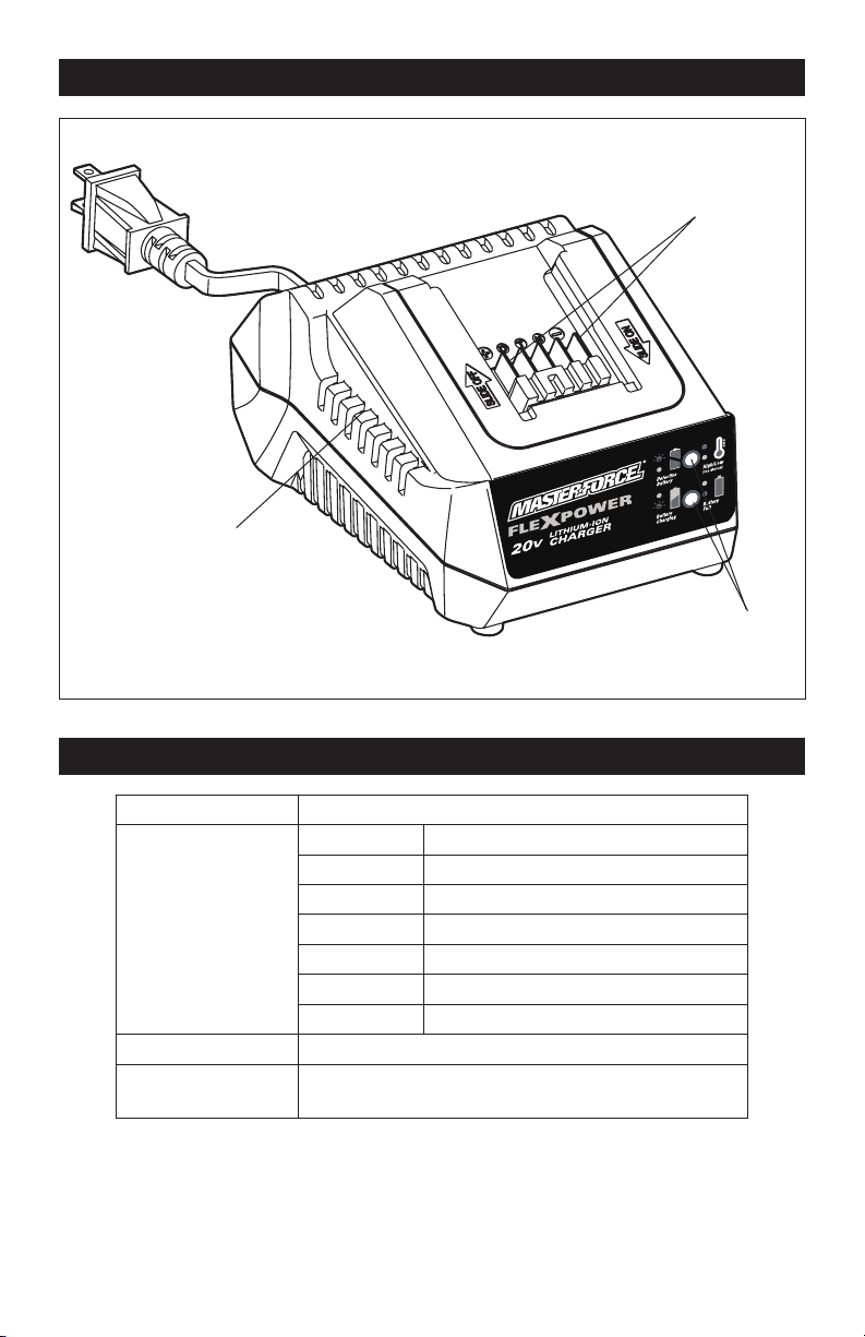
Page 6
OVERVIEW
Electrical contacts
LED lights
Air vents
SPECIFICATIONS
Charger Input 120V~ 60 Hz 45W
Charging Time For
Batteries
60 minutes 20V 1.5Ah Li-Ion (252-8029)
70 minutes 20V 2.0Ah Li-Ion (252-8031)
90 minutes 20V 2.5Ah Li-Ion (252-8030, 252-8003)
140 minutes 20V 4.0Ah Li-Ion (252-8034)
140 minutes 20V 4.0Ah Li-Ion (252-8013)
170 minutes 20V 5.0Ah Li-ion( 252-8035, 252-8005)
250 minutes 20V 7.5Ah Li-ion (252-8007)
Charger Weight 1 lb. (0.45kg)
Optimum Charging
Temperature
41-104°F (5-40°C)

Page 7
ASSEMBLY
WARNING:
If any part is broken
or missing, DO NOT attempt to plug in the
power cord, attach the battery, or operate
the tool until the broken or missing part is
replaced. Failure to do so could result in
possible serious injury.
WARNING:
Do not attempt to
modify this tool or create accessories not
recommended for use with this tool. Any
such alteration or modification is misuse
and could result in a hazardous condition
leading to possible serious injury.
WARNING:
Your tool should
never be connected to the power source
when you are assembling parts, making
adjustments, installing or removing
application tools, cleaning, or when it is
not in use. Disconnecting the tool will
prevent accidental starting, which could
cause serious personal injury.
CONTENTS
Battery charger and instruction manual
UNPACKING
1. Carefully remove the tool and any
accessories from the carton. Make sure
that all items listed in the packing list are
included.
2. Inspect the tool carefully to make sure
no breakage or damage occurred during
shipping.
3. Do not discard the packing material
until you have carefully inspected and
satisfactorily operated the tool.
Page 8
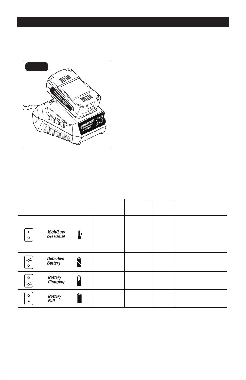
OPERATION
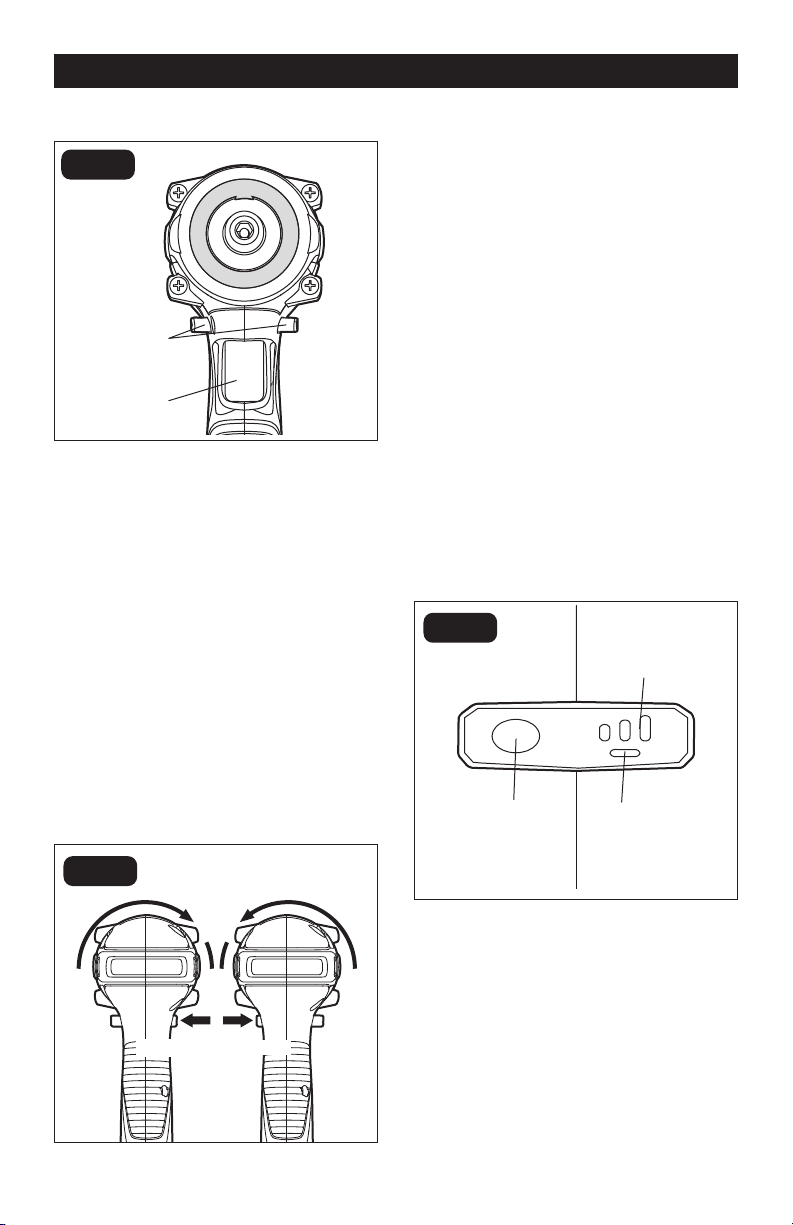
HOW TO CHARGE
THE BATTERY PACK (FIG. 1)
FIG. 1
A fully discharged battery pack will charge
in about 60-250 minutes, depending on the
battery, at a temperature between 41-104°F
( 5-40°C).
1. Connect the charger to a correct power
supply (120V~ 60Hz).
2. Attach the battery pack to the charger by
aligning the raised ribs of the battery pack
with the slot in the charger. Slide the battery
pack onto the charger (FIG. 1).
3. The charger will communicate with
the battery pack circuitry to evaluate the
condition of the battery pack.
4. The green LED light will flash continuously
during normal charging.
5. After charging is complete, the green LED
on the charger will remain on.
6. The battery pack will fully charge, but will
not overcharge, if left on the charger.
LED FUNCTIONS OF CHARGER
LED INDICATOR
BATTERY
PACK
RED LED
GREEN
LED
ACTION
Hot/Cold
battery
On Off
Fast charge will
begin when the
battery returns
to desired
temperature.
Defective Flashing Off
Battery pack or
charger is defective.
Charging Off Flashing Charging
Fully
charged
Off On
Charging is
complete.

Page 9
CHARGING A HOT
BATTERY PACK
If the battery pack is above the normal
temperature range, the red LED will
illuminate and the green LED will be off.
When the battery pack cools down to
approximately 104°F (40°C), the charger will
automatically begin charging.
CHARGING A COLD
BATTERY PACK
If the battery pack is below the normal
temperature range, the red LED will
illuminate and the green LED will be off.
When the battery warms to a temperature
of 41°F (5°C), the charger will automatically
begin charging.
DEFECTIVE BATTERY
If the charger detects a problem, the red
LED will begin flashing and the green LED
will be off.
1. If registering as defective, remove and
reinsert the battery pack in the charger. If
the LED status reads “defective” a second
time, try to charge a different battery pack.
2. If a different battery pack charges
normally, dispose of the defective battery
pack (see Maintenance section).
3. If a different battery pack also indicates
“defective,” the charger may be defective.
OPERATION
BATTERY CHARGING
If the battery pack is within the normal
temperature range, the green LED will begin
flashing and the red LED will be off.
BATTERY FULL
After the battery is fully charged, the green
LED light on the charger will be on and the
red LED light will be off.
NOTICE: The battery pack will fully charge,
but will not overcharge, if left on the charger.
NOTICE: Charger may warm with several
continuous charge cycles. This is part of
the normal operation of the charge. Always
charge in a well-ventilated area.

Page 10
MAINTENANCE
WARNING:
To avoid serious
personal injury, always disconnect the plug
from the power source when cleaning or
performing any maintenance. Contact a
qualified service technician for all repairs.
WARNING:
When servicing, use
only identical replacement parts. Use of any
other parts may create a hazard or cause
product damage. For more information, call
the toll-free helpline, at 1-866-917-4374.
WARNING:
Avoid using solvents
when cleaning plastic parts. Most plastics
are susceptible to damage from various
types of commercial solvents and may be
damaged by their use. Use a clean cloth to
remove dirt, dust, oil, grease, etc.
WARNING:
If the supply cord
is damaged, it must be replaced by a
specially prepared cord available through
the service organization.
TROUBLESHOOTING
PROBLEM CAUSE OF THE PROBLEM SOLUTION
The battery pack isn’t
charging.
Unconnected to charger. Attach the battery pack to
the charger.

Page 11
Page 17
NOTES

Page 12
Page 17
NOTES

Page 13
Page 17
NOTES

Page 14
SAVE YOUR RECEIPTS
THIS WARRANTY IS VOID WITHOUT THEM
WARRANTY
90-DAY MONEY BACK GUARANTEE:
This MASTERFORCE
®
brand power tool carries our 90-DAY Money Back
Guarantee. If you are not completely satisfied with your MASTERFORCE
®
brand
power tool for any reason within ninety (90) days from the date of purchase, return
the tool with your original receipt to any MENARDS
®
retail store, and we will provide
you a refund – no questions asked.
3-YEAR LIMITED WARRANTY:
This MASTERFORCE
®
brand power tool carries our famous No Hassle 3-Year
Limited Warranty to the original purchaser. If, during normal use, this
MASTERFORCE
®
power tool breaks or fails due to a defect in material or
workmanship within three (3) years from the date of original purchase, simply bring
this tool with the original sales receipt back to your nearest MENARDS
®
retail store.
At its discretion, MASTERFORCE
®
agrees to have the tool or any defective part(s)
repaired or replaced with the same or similar MASTERFORCE
®
product or part
free of charge, within the stated warranty period, when returned by the original
purchaser with original sales receipt. Not withstanding the foregoing, this limited
warranty does not cover any damage that has resulted from abuse or misuse of the
Merchandise. This warranty: (1) excludes expendable parts including but not limited
to blades, brushes, belts, bits, light bulbs, and/or batteries; (2) shall be void if this
tool is used for commercial and/or rental purposes; and (3) does not cover any
losses, injuries to persons/property or costs. This warranty does give you specific
legal rights and you may have other rights, which vary from state to state. Be
careful, tools are dangerous if improperly used or maintained. Seller’s employees
are not qualified to advise you on the use of this Merchandise. Any oral
representation(s) made will not be binding on seller or its employees. The rights
under this limited warranty are to the original purchaser of the Merchandise and may
not be transferred to any subsequent owner. This limited warranty is in lieu of all
warranties, expressed or implied including warranties or merchantability and fitness
for a particular purpose. Seller shall not be liable for any special, incidental, or
consequential damages. The sole exclusive remedy against the seller will be for the
replacement of any defects as provided herein, as long as the seller is willing or
able to replace this product or is willing to refund the purchase price as provided
above. For insurance purposes, seller is not allowed to demonstrate any of these
power tools for you.
For questions / comments, technical assistance or repair parts – Please Call Toll
Free at: 1-866-917-4374. (M-F 8:30am-5:00pm Est.)
20 Volt LITHIUM-ION CHARGER

01/2023
© 2023 Menard, Inc., Eau Claire, WI 54703
252-8031
OPERATOR’S MANUAL
CAUTION:
To Reduce The Risk Of Injury, User Must
Read And Understand Operator’s Manual. Save These
Instructions For Future Reference.
For questions / comments, technical assistance or repair parts –
Please Call Toll Free: 1-866-917-4374. (M-F 8:30am – 5:00pm Est.)
20V Lithium-Ion Battery Pack

TABLE OF CONTENTS
Safety Symbols ......................................................... Page 2
Safety Instructions ...................................................... Page 3
Overview/Specifications ................................................. Page 6
Assembly ............................................................. Page 7
Operation ............................................................. Page 8
Maintenance .......................................................... Page 11
Troubleshooting ....................................................... Page 12

Page 2
SAFETY SYMBOLS
Some of these following symbols may be used on this tool. Please study them and learn their
meaning. Proper interpretation of these symbols will allow you to operate the tool better and
more safely.
Symbol
Name
Designation / Explanation
V Volts Voltage
A Amperes Current
Hz Hertz Frequency (cycles per second)
Wh Watt-hours Battery capacity
Ah
Ampere-hours Battery capacity
�
or d.c.
Direct current Type or characteristic of current
n
o
No-load speed Rotational speed at no load
lbs Pounds Weight
Read instruction
manual
To reduce the risk of injury, user must
read instruction manual.
Li-ion RBRC seal
Designates Li-ion battery recycling pro-
gram.
WARNING:
To ensure safety and reliability, all repairs should be performed by a
qualified service technician.

Page 3
SAFETY INSTRUCTIONS
The purpose of safety symbols is to attract your attention to possible dangers. The safety
symbols and the explanations with them deserve your careful attention and understanding.
The symbol warnings do not, by themselves, eliminate any danger. The instructions and
warnings they give are no substitutes for proper accident prevention measures.
WARNING:
Be sure to read and understand all safety instructions in this manual,
including all safety alert symbols such as “DANGER,” ”WARNING,” and “CAUTION”
before using this tool. Failure to follow all instructions listed below may result in electric
shock, fire, and/or serious personal injury.
SYMBOL MEANING
SAFETY ALERT SYMBOL: Indicates DANGER, WARNING, OR CAUTION.
May be used in conjunction with other symbols or pictographs.
DANGER:
Indicates an imminently hazardous situation, which, if not avoided,
will result in death or serious injury.
WARNING:
Indicates a potentially hazardous situation, which, if not avoided,
could result in death or serious injury.
CAUTION:
Indicates a potentially hazardous situation, which, if not avoided, could
result in minor or moderate injury.
NOTICE: (Without Safety Alert Symbol) Indicates a situation that may result in property
damage.
SAVE THESE INSTRUCTIONS!

Page 4
SAFETY INSTRUCTIONS
WARNING:
Read all safety
warnings and instructions!
Failure to follow the warnings and
instructions may result in electric shock, fire
and/or serious injury. Save all warnings and
instructions for future reference.
The “term power tool” in the warnings refers
to your mains-operated (corded) power tool
or battery-operated (cordless) power tool.
WARNING:
Risk of fire and
electric shock. Dry location use only. Do
not expose to rain. Risk of injury.
WORK AREA SAFETY
1. Keep the work area clean and well lit.
Cluttered or dark areas invite accidents.
2. Do not operate power tools in explosive
atmospheres, such as in the presence of
flammable liquids, gases or dust. Power
tools create sparks that may ignite the dust
or fumes.
3. Keep children and bystanders away
while operating a power tool. Distractions
can cause you to lose control.
ELECTRICAL SAFETY
1. Avoid body contact with earthed
or grounded surfaces, such as pipes,
radiators, ranges and refrigerators. There
is an increased risk of electric shock if your
body is earthed or grounded.
2. Do not expose power tools to rain or
wet conditions. Water entering a power tool
will increase the risk of electric shock.
BATTERY TOOL USE
AND CARE
1. Recharge only with the charger
specified by the manufacturer. A charger
that is suitable for one type of battery pack
may create a risk of fire when used with
another battery pack.
2. Use power tools only with specifically
designated battery packs. Use of any
other battery packs may create a risk of
injury and fire.
3. When the battery pack is not in use,
keep it away from other metal objects,
such as paper clips, coins, keys, nails,
screws or other small metal objects that
can make a connection from one terminal
to another. Shorting the battery terminals
together may cause burns or a fire.
4. Under abusive conditions, liquid may
be ejected from the battery; avoid contact.
If contact accidentally occurs, flush with
water. If liquid contacts eyes, also seek
medical help. Liquid ejected from the battery
may cause irritation or burns.
SERVICE
1. Have your power tool serviced by a
qualified repair person, using only identical
replacement parts. This will ensure that the
safety of the power tool is maintained.
SPECIFIC SAFETY RULES FOR
BATTERY PACK
1. Use battery only with MASTERFORCE
®
chargers listed.
Battery pack Charger
252-8031
252-8025
252-8026
252-8037
252-8043

Page 5
SAFETY INSTRUCTIONS
2. Know your power tool. Read the
Instruction Manual carefully. Learn the tool’s
applications and limitations, as well as the
specific potential hazards related to this
tool. Following this rule will reduce the risk
of electric shock, fire, and serious injury.
3. Do not place the battery near fire or
heat. This will reduce the risk of explosion
and possible injury.
4. Do not crush, drop or damage the
battery pack. Do not use a battery pack or
charger that has been dropped or received
a sharp blow. A damaged battery is subject
to explosion. Properly dispose of a dropped
or damaged battery immediately.
5. Batteries vent hydrogen gas and can
explode in the presence of a source of
ignition, such as a pilot light. To reduce
the risk of serious personal injury, never use
any cordless product in the presence of an
open flame. An exploded battery can propel
debris and chemicals. If exposed, flush the
exposed area with water immediately.
6. Do not charge the battery in a damp or
wet location. Following this rule will reduce
the risk of electric shock.
7. For best results, your battery should
be charged, used and stored in a location
where the temperature is more than 41°F
(5°C) but less than 104°F (40°C). Do not
store outside or in vehicles.
8. Under extreme usage or temperature
conditions, battery leakage may occur.
If liquid comes in contact with your skin,
wash immediately with soap and water,
then neutralize with lemon juice or vinegar.
If liquid gets in your eyes, flush them with
clean water for at least 10 minutes, and
then seek immediate medical attention.
Following this rule will reduce the risk of
serious personal injury.
9. Do not let gasoline, oils, petroleum-
based products, etc. come in contact with
plastic parts. They contain chemicals that
can damage, weaken or destroy plastic.
10. Have your battery pack serviced by a
qualified repair person using only identical
replacement parts. This will ensure that the
safety of the battery pack is maintained.
11. Save these instructions. Refer to them
frequently and use them to instruct others
who may use this tool. If you lend someone
this tool, lend these instructions also to
prevent misuse of the product and possible
injury.
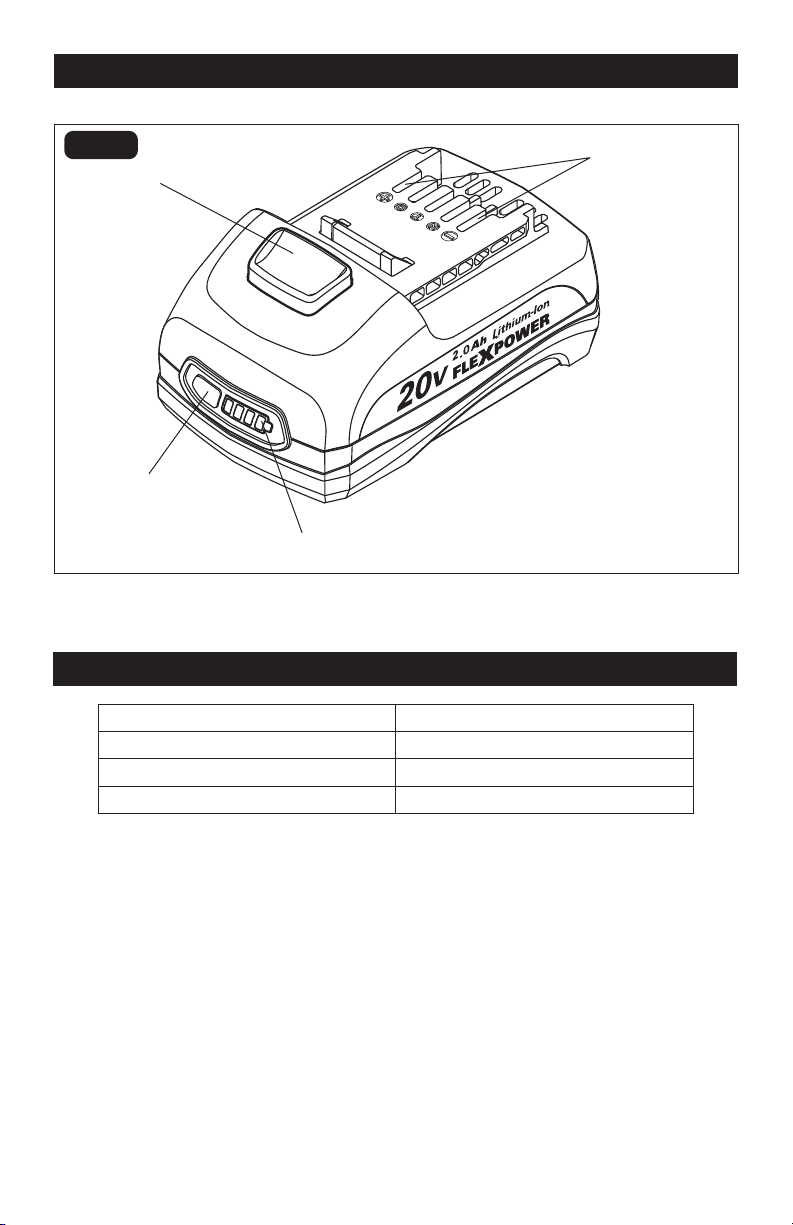
Page 6
OVERVIEW
Electrical contacts
Power-indicator button
Battery-release button
Power indicator
SPECIFICATIONS
Battery Type Lithium-Ion
Battery Voltage 20V d.c.
Battery Weight 1.0 lb. (0.45kg)
Battery Capacity 2.0Ah
FIG. 1

Page 7
WARNING:
If any part is broken
or missing, DO NOT attempt to plug in the
power cord, attach the battery, or operate
the tool until the broken or missing part is
replaced. Failure to do so could result in
possible serious injury.
WARNING:
Do not attempt to
modify this tool or create accessories not
recommended for use with this tool. Any
such alteration or modification is misuse
and could result in a hazardous condition
leading to possible serious injury.
WARNING:
Your tool should
never be connected to the power source
when you are assembling parts, making
adjustments, installing or removing
application tools, cleaning, or when it is
not in use. Disconnecting the tool will
prevent accidental starting, which could
cause serious personal injury.
ASSEMBLY
CONTENTS
Battery pack and instruction manual
UNPACKING
1. This product has been shipped
completely assembled.
2. Carefully remove the tool and any
accessories from the box. Make sure
that all items listed in the packing list
are included.
3. Inspect the tool carefully to make sure
that no breakage or damage occurred
during shipping.
4. Do not discard the packing material
until you have carefully inspected and
satisfactorily operated the tool.
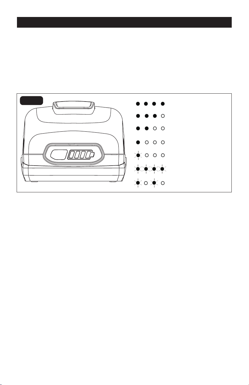
Page 8
OPERATION
POWER INDICATOR (Fig. 2)
This Lithium-Ion battery pack is equipped with
a power indicator that displays the battery
pack’s charge status. Press the power-
indicator button to display the LED lights.
The LED lights will stay lit for approximately
4 seconds.
LOW CAPACITY WARNING
If one LED on the power indicator begins to
flash, the battery pack’s charge is under 20%
capacity and should be recharged soon.
Unlike other battery pack types, Lithium-Ion
battery packs deliver fade-free power for their
entire run time. The tool will not experience a
slow, gradual loss of power as you work. To
signal that the battery pack is at the end of its
run time and needs to be charged, power to
the tool will drop quickly.
The power indicator will begin to display
four flashing LED lights when it is completely
discharged. When this happens, remove
the tool from the workpiece and charge the
battery pack as needed.
BATTERY PROTECTION
To protect the battery from damage and
prolong its life, the battery pack circuitry
will turn off the battery pack if it becomes
overloaded or if the temperature becomes too
high during use. This may happen in extremely
high torque, binding and stalling situations.
The battery pack will begin normal operation
when it cools down.
The power indicator will display four flashing
LED lights if the circuitry detects a momentary
overload. You can conveniently reset the
battery pack by releasing the power-tool
trigger. Press the power-indicator button
again to display the remaining charge.
NOTICE: If the power indicator continues to
flash four LED lights after resetting, place
the battery pack on the charger to evaluate
the battery condition.
NOTICE: A significantly reduced run time
after fully charging the battery pack indicates
that the battery is near the end of its usable
life and must be replaced.
FIG. 2
80-100% Charge
60-79% Charge
40-59% Charge
20-39% Charge
Under 20% Charge
Completely Discharged
High/low temperature
NOTICE: The power indicator can be used
whether the battery is attached to or removed
from the tool.
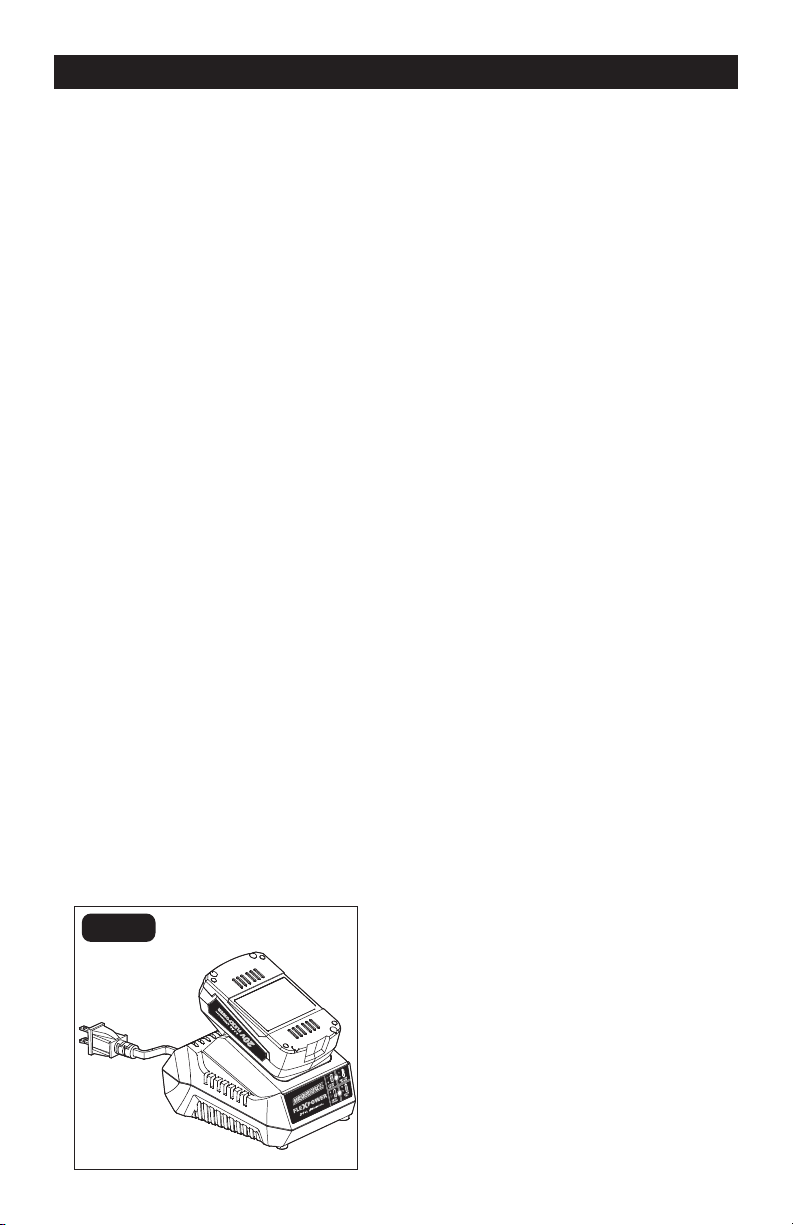
Page 9
OPERATION
COLD WEATHER OPERATION
When the battery pack is very cold, it may
“pulse” for the first minute of use to warm
itself. Put the battery pack on a tool and use
the tool in a light application. After about a
minute, the battery pack will have warmed
itself and will operate normally.
WHEN TO CHARGE THE
BATTERY PACK
The Lithium-Ion battery can be charged at
any time and will not develop a “memory”
when charged after only a partial discharge.
It is not necessary to run down the battery
pack charge before recharging. Remove
the battery pack from the tool when it is
convenient for you and your job.
1. Use the power indicator to determine when
you need to recharge the battery pack.
2. You can “top-off” your battery pack’s
charge before starting a big job or long
period of use.
3. Due to Lithium-Ion’s fade-free
properties, the only time it is necessary
to charge the Lithium- Ion battery pack
is when the pack has reached the end of
its charge. To signal the end of charge,
power to the tool will drop quickly.
Charge the battery pack as needed.
HOW TO CHARGE THE BATTERY
PACK (FIG. 3)
A fully discharged battery pack will charge
about 70 minutes (with charger 252-8025) in
the desired surrounding temperature.
1. Charge the battery pack with the correct
charger.
2. Connect the charger to a power supply .
3. Attach the battery pack to the charger
by aligning the raised ribs of the battery
pack with the slot in the charger. Slide
the battery pack onto the charger.
4. The charger will communicate with the
battery pack’s circuitry to evaluate the
condition of the battery pack.
5. During normal charging, the green LED
on the charger will flash continuously.
6. After charging is complete, the green
LED on the charger will be on. The
power indicator LED lights will not be
displayed when the power-indicator
button is pressed while the battery pack
is on the charger.
7. The battery pack will fully charge, but
will not overcharge, if left on the charger.
HOW TO KNOW THE CHARGE
CONDITION OF BATTERY PACK
DURING CHARGING
The LED lights on the battery pack are
displayed as the pack is being charged,
indicating how fully charged the pack is.
• The first LED light on the battery pack
flashes to indicate that the battery pack is
0%-25% charged.
• The first LED light on the battery pack is
solid and the second flashes to indicate
that the battery pack is 25%-50% charged.
• The first two LED lights on the battery pack
are solid and the third flashes to indicate
that the battery pack is 50%-75% charged.
• The first three LED lights on the battery
pack are solid and the fourth flashes to
indicate that the battery pack is 75%-
100% charged.
• When it is fully charged, all the LED lights
on the battery pack will be solid for about
30 minutes then will turn off.
FIG. 3
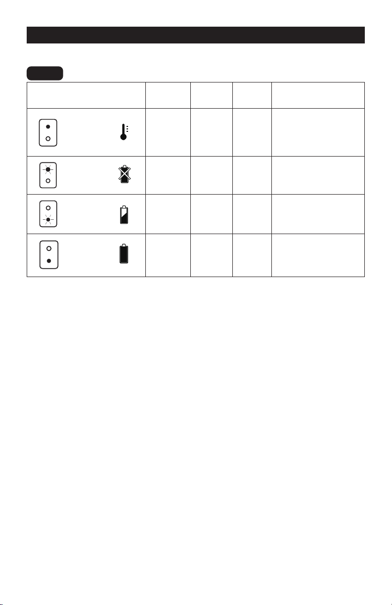
Page 10
OPERATION
CHARGING A HOT
BATTERY PACK
If the battery pack is above the normal
temperature range, the red LED will
illuminate and the green LED will be off.
When the battery pack cools down to
approximately 104°F (40°C), the charger will
automatically begin charging.
CHARGING A COLD
BATTERY PACK
If the battery pack is below the normal
temperature range, the red LED will
illuminate and the green LED will be off.
When the battery warms to a temperature
of more than 41°F (5°C), the charger will
automatically begin charging .
LED FUNCTIONS OF CHARGER (FIG. 4)
LED INDICATOR
BATTERY
PACK
RED
LED
GREEN
LED
ACTION
HI / LO TEMP.
Hot/Cold
battery
On Off
Fast charge will begin
when battery returns
to between 41°F (5°C)
and 104°F (40°C)
DEFECTIVE
BATTERY
Defective Flashing Off
Battery pack or
charger is defective
BATTERY
CHARGING
Charging Off Flashing Charging
BA TTERY
FULL
Fully
charged
Off On
Charging is
complete
DEFECTIVE BATTERY
If the charger detects a problem, the red LED
will begin flashing and the green LED will be off.
1. If registering as defective, remove and
reinsert the battery pack in the charger.
If the LED status indicates “defective”
a second time, try to charge a different
battery pack.
2. If a different battery pack charges
normally, dispose of the defective
battery pack (see Maintenance section).
3. If a different battery pack also indicates
“defective,” the charger may be defective.
FIG. 4

Page 11
MAINTENANCE
WARNING:
To ensure safety and
reliability, all repairs should be performed
by a qualified service technician.
WARNING:
Always wear safety
goggles or safety glasses with side
shields when using compressed air to
clean tool. If the operation is dusty, also
wear a dust mask.
WARNING:
To avoid serious
personal injury, always remove the battery
pack from the tool when cleaning or
performing any maintenance.
BATTERIES:
The battery pack is equipped with Lithium-
Ion rechargeable batteries. The duration of
use from each charge will depend on the
type of work performed.
The batteries in this tool have been designed
to provide maximum trouble-free life. Like
all batteries, they will eventually wear out.
Do not disassemble the battery pack or
attempt to replace the batteries. Handling
the batteries, especially when wearing rings
and jewelry, could result in a serious burn.
To obtain the longest possible battery life,
read and understand the operator’s manual.
It is good practice to unplug the Charger
and remove the Lithium-Ion battery pack
when it is not in use. For Lithium-Ion battery
pack storage longer than 30 days:
1. Store Lithium-Ion battery packs in a
30%-50% charged condition.
2. Every six months of storage, fully charge
the Lithium-Ion battery pack.
3. The exterior may be cleaned with a cloth
or soft non-metallic brush.
BATTERY PACK REMOVAL AND
PREPARATION FOR RECYCLING
To preserve natural resources, please
recycle or dispose of batteries properly.
This product contains Lithium-Ion batteries.
Local, state, or federal laws may prohibit
disposal of Lithium-Ion batteries in ordinary
trash. Consult your local waste authority for
information regarding available recycling
and/or disposal options.
WARNING:
Upon removal of the
battery pack for disposal or recycling,
cover the battery pack’s terminals
with heavy-duty adhesive tape. Do not
attempt to destroy or disassemble battery
pack or remove any of its components.
Lithium-Ion batteries must be recycled or
disposed of properly. Never touch both
terminals with metal objects and/or body
parts as short circuit may result. Keep
away from children. Failure to comply with
these warnings could result in fire and/or
serious injury.

Page 12
TROUBLESHOOTING
PROBLEM CAUSE SOLUTION
The battery pack
isn’t charging
Unconnected to charger
Attach the battery pack to
the charger.

Page 13
NOTES

Page 14
NOTES

11/2022
© 2022 Menard, Inc., Eau Claire, WI 54703