
241-0485
17 19 21 23
OPERATOR’S MANUAL
CAUTION:
To Reduce the Risk of Injury, User Must
Read and Understand the Operator’s Manual. Save These
Instructions For Future Reference.
For questions / comments, technical assistance or repair parts –
Please Call Toll Free: 1-866-917-4374. (M-F 8:30am-5:00pm Est.)
BRUSHLESS DRILL/DRIVER

TABLE OF CONTENTS
Safety Symbols ......................................................... Page 2
Safety Instructions ...................................................... Page 4
Overview/Specifications ................................................. Page 8
Assembly ............................................................. Page 9
Operation ............................................................. Page 9
Maintenance .......................................................... Page 16
Troubleshooting ....................................................... Page 17
Warranty .............................................................Page 18

Page 2
SAFETY SYMBOLS
Some of these following symbols may be used on this tool. Please study them and learn their
meaning. Proper interpretation of these symbols will allow you to operate the tool better and
more safely.
Symbol
Name
Designation / Explanation
V Volts Voltage
A Amps Current
Hz Hertz Frequency (cycles per second)
W Watts Power
lbs Pounds Weight
n
o
No-load Speed Rotational speed at no load
RPM
Revolutions per
Minute
Unit of speed
�
or d.c Direct Current Type of characteristic of current
WARNING:
To ensure safety and reliability, all repairs should be performed by a
qualified service technician.

Page 3
SAFETY INSTRUCTIONS
The purpose of safety symbols is to attract your attention to possible dangers. The safety
symbols and the explanations with them deserve your careful attention and understanding.
The symbol warnings do not, by themselves, eliminate any danger. The instructions and
warnings they give are no substitutes for proper accident prevention measures.
WARNING:
Be sure to read and understand all safety instructions in this manual,
including all safety alert symbols such as “DANGER,” ”WARNING,” and “CAUTION”
before using this tool. Failure to following all instructions listed below may result in
electric shock, fire, and/or serious personal injury.
SYMBOL MEANING
SAFETY ALERT SYMBOL: Indicates DANGER, WARNING, OR CAUTION.
May be used in conjunction with other symbols or pictographs.
DANGER:
Indicates an imminently hazardous situation, which, if not avoided,
will result in death or serious injury.
WARNING:
Indicates a potentially hazardous situation, which, if not avoided,
could result in death or serious injury.
CAUTION:
Indicates a potentially hazardous situation, which, if not avoided, could
result in minor or moderate injury.
NOTICE: (Without Safety Alert Symbol) Indicates a situation that may result in property
damage.
SAVE THESE INSTRUCTIONS!

Page 4
GENERAL POWER TOOL
SAFETY WARNINGS
WARNING:
Read all safety
warnings, instructions, illustrations and
specifications provided with this power
tool. Failure to follow all instructions listed
below may result in electric shock, fire and/or
serious injury.
SAVE ALL WARNINGS AND INSTRUCTIONS
FOR FUTURE REFERENCE.
The term “power tool” in the warnings refers
to your mains-operated (corded) power tool
or battery-operated (cordless) power tool.
WORK AREA SAFETY
1. Keep work area clean and well lit.
Cluttered or dark areas invite accidents.
2. Do not operate power tools in explosive
atmospheres, such as in the presence of
flammable liquids, gases or dust. Power
tools create sparks which may ignite the
dust or fumes.
3. Keep children and bystanders away
while operating a power tool. Distractions
can cause you to lose control.
ELECTRICAL SAFETY
1. Power tool plugs must match the
outlet. Never modify the plug in any way.
Do not use any adapter plugs with earthed
(grounded) power tools. Unmodified plugs
and matching outlets will reduce risk of
electric shock.
2. Avoid body contact with earthed
or grounded surfaces, such as pipes,
radiators, ranges and refrigerators. There
is an increased risk of electric shock if your
body is earthed or grounded.
3. Do not expose power tools to rain or
wet conditions. Water entering a power tool
will increase the risk of electric shock.
4. Do not abuse the cord. Never use the
cord for carrying, pulling or unplugging the
power tool. Keep cord away from heat, oil,
sharp edges or moving parts. Damaged or
entangled cords increase the risk of electric
shock.
5. When operating a power tool outdoors,
use an extension cord suitable for outdoor
use. Use of a cord suitable for outdoor use
reduces the risk of electric shock.
6. If operating a power tool in a damp
location is unavoidable, use a ground fault
circuit interrupter (GFCI) protected supply.
Use of an GFCI reduces the risk of electric
shock.
PERSONAL SAFETY
1. Stay alert, watch what you are doing
and use common sense when operating a
power tool. Do not use a power tool while
you are tired or under the influence of
drugs, alcohol or medication. A moment of
inattention while operating power tools may
result in serious personal injury.
2. Use personal protective equipment.
Always wear eye protection. Protective
equipment such as a dust mask, non-skid
safety shoes, hard hat or hearing protection
used for appropriate conditions will reduce
personal injuries.
3. Prevent unintentional starting. Ensure
the switch is in the off-position before
connecting to power source and/or battery
pack, picking up or carrying the tool.
Carrying power tools with your finger on the
switch or energising power tools that have
the switch on invites accidents.
4. Remove any adjusting key or wrench
before turning the power tool on. A wrench
or a key left attached to a rotating part of the
power tool may result in personal injury.
5. Do not overreach. Keep proper footing
and balance at all times. This enables better
control of the power tool in unexpected
situations.
SAFETY INSTRUCTIONS

Page 5
SAFETY INSTRUCTIONS
6. Dress properly. Do not wear loose
clothing or jewellery. Keep your hair and
clothing away from moving parts. Loose
clothes, jewellery or long hair can be caught
in moving parts.
7. If devices are provided for the
connection of dust extraction and
collection facilities, ensure these are
connected and properly used. Use of dust
collection can reduce dust-related hazards.
8. Do not let familiarity gained from
frequent use of tools allow you to become
complacent and ignore tool safety
principles. A careless action can cause
severe injury within a fraction of a second.
POWER TOOL USE
AND CARE
1. Do not force the power tool. Use the
correct power tool for your application. The
correct power tool will do the job better and
safer at the rate for which it was designed.
2. Do not use the power tool if the switch
does not turn it on and off. Any power tool
that cannot be controlled with the switch is
dangerous and must be repaired.
3. Disconnect the plug from the power
source and/or remove the battery pack,
if detachable, from the power tool before
making any adjustments, changing
accessories, or storing power tools. Such
preventive safety measures reduce the risk of
starting the power tool accidentally.
4. Store idle power tools out of the reach
of children and do not allow persons
unfamiliar with the power tool or these
instructions to operate the power tool.
Power tools are dangerous in the hands of
untrained users.
5. Maintain power tools and accessories.
Check for misalignment or binding of
moving parts, breakage of parts and
any other condition that may affect the
power tool’s operation. If damaged, have
the power tool repaired before use. Many
accidents are caused by poorly maintained
power tools.
6. Keep cutting tools sharp and clean.
Properly maintained cutting tools with sharp
cutting edges are less likely to bind and are
easier to control.
7. Use the power tool, accessories
and tool bits etc. in accordance with
these instructions, taking into account
the working conditions and the work to
be performed. Use of the power tool for
operations different from those intended
could result in a hazardous situation.
8. Keep handles and grasping surfaces
dry, clean and free from oil and grease.
Slippery handles and grasping surfaces do
not allow for safe handling and control of the
tool in unexpected situations.
BATTERY TOOL USE
AND CARE
1. Recharge only with the charger
specified by the manufacturer. A charger
that is suitable for one type of battery pack
may create a risk of fire when used with
another battery pack.
2. Use power tools only with specifically
designated battery packs. Use of any other
battery packs may create a risk of injury and
fire.
3. When battery pack is not in use, keep
it away from other metal objects, like
paper clips, coins, keys, nails, screws or
other small metal objects, that can make
a connection from one terminal to another.
Shorting the battery terminals together may
cause burns or a fire.

Page 6
SAFETY INSTRUCTIONS
4. Under abusive conditions, liquid may
be ejected from the battery; avoid contact.
If contact accidentally occurs, flush with
water. If liquid contacts eyes, additionally
seek medical help. Liquid ejected from the
battery may cause irritation or burns.
5. Do not use a battery pack or tool that
is damaged or modified. Damaged or
modified batteries may exhibit unpredictable
behaviour resulting in fire, explosion or risk
of injury.
6. Do not expose a battery pack or tool
to fire or excessive temperature. Exposure
to fire or temperature above 100 °C (212 °F)
may cause explosion.
7. Follow all charging instructions and
do not charge the battery pack or tool
outside the temperature range specified
in the instructions. Charging improperly or
at temperatures outside the specified range
may damage the battery and increase the
risk of fire.
SERVICE
1. Have your power tool serviced by a
qualified repair person using only identical
replacement parts. This will ensure that the
safety of the power tool is maintained.
2. Never service damaged battery
packs. Service of battery packs should
only be performed by the manufacturer or
authorized service providers.
SAFETY INSTRUCTIONS FOR
ALL OPERATIONS
1. Use the auxiliary handle. Loss of control
can cause personal injury.
2. Hold the power tool by insulated
gripping surfaces, when performing an
operation where the cutting accessory may
contact hidden wiring. Cutting accessory
or fasteners contacting a “live” wire may
make exposed metal parts of the power tool
“live” and could give the operator an electric
shock.
SAFETY INSTRUCTIONS WHEN
USING LONG DRILL BITS
• Never operate at higher speed than
the maximum speed rating of the drill bit.
At higher speeds, the bit is likely to bend if
allowed to rotate freely without contacting
the workpiece, resulting in personal injury.
• Always start drilling at low speed
and with the bit tip in contact with the
workpiece. At higher speeds, the bit is likely
to bend if allowed to rotate freely without
contacting the workpiece, resulting in
personal injury.
• Apply pressure only in direct line
with the bit and do not apply excessive
pressure. Bits can bend causing breakage
or loss of control, resulting in personal injury.
Page 7
WARNING:
Some dust created
by power sanding, sawing, grinding,
drilling, and other construction activities
contains chemicals known to the state
of California to cause cancer, birth
defects, or other reproductive harm.
Some examples of these chemicals are:
• Lead from lead-based paints
• Crystalline silica from bricks, cement,
and other masonry products
• Arsenic and chromium from
chemically-treated lumber
Your risk from these exposures varies,
depending upon how often you do this
type of work. To reduce your exposure
to these chemicals:
• Work in a well-ventilated area.
• Work with approved safety
equipment, such as dust masks that
are specially designed to filter out
microscopic particles.
• Avoid prolonged contact with dust
from power sanding, sawing, grinding,
drilling, and other construction activities.
Wear protective clothing and wash
exposed areas with soap and water.
Allowing dust to get into your mouth or
eyes or to lie on the skin may promote
absorption of harmful chemicals.
SAVE THESE INSTRUCTIONS!
IMPORTANT SAFETY
INSTRUCTIONS
1. To reduce the risk of electric shock
or damage to the chargers and batteries,
use only with the MASTERFORCE
®
FLEXPOWER
®
battery packs and chargers
listed.
Battery pack Charger
252-8029 (1.5Ah)
252-8031 (2.0Ah)
252-8030 (2.5Ah)
252-8034 (4.0Ah)
252-8035 (5.0Ah)
252-8027 (7.5Ah)
252-8003 (2.5Ah Boost)
252-8007 (7.5Ah Boost)
252-8025
252-8037
252-8026
2. For best results, your battery and tool
should be stored, charged and used in a
location where the temperature is more
than 5°C (41°F) but less than 40°C (104°F).
Do not store outside or in vehicles.
DANGER:
People with electronic
devices, such as pacemakers, should
consult their physician(s) before using this
product. Operation of electrical equipment
in close proximity to a heart pacemaker
could cause interference or failure of the
pacemaker.
SAFETY INSTRUCTIONS
Page 8
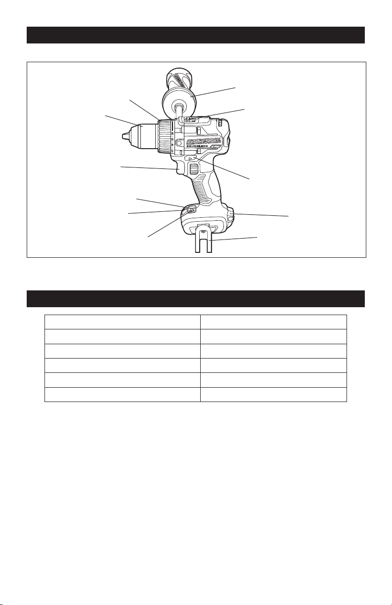
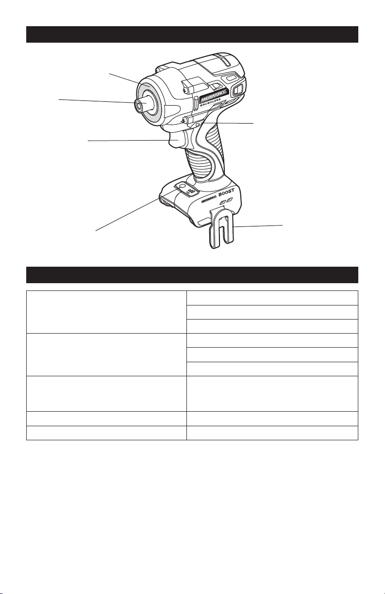
OVERVIEW
17 19 21 23
Chuck Sleeve
Side Handle
Variable-Speed
Trigger Switch
Direction-Of-Rotation
Selector (Forward/
Center-Lock/Reverse)
LED Worklight
Torque-Adjustment Ring
Two-Speed Gearbox Switch
Impulse Button
Impulse Indicator
Bit Holder
Belt Clip
SPECIFICATIONS
Rated Voltage 20 V d.c.
No-load Speed 0-550/0-2,000 RPM
Chuck Capacity 1/2” (13mm)
Max. Torque 800 in. lbs.
Clutch 23+1 positions
Weight (without battery) 3 lb 8oz
Page 9
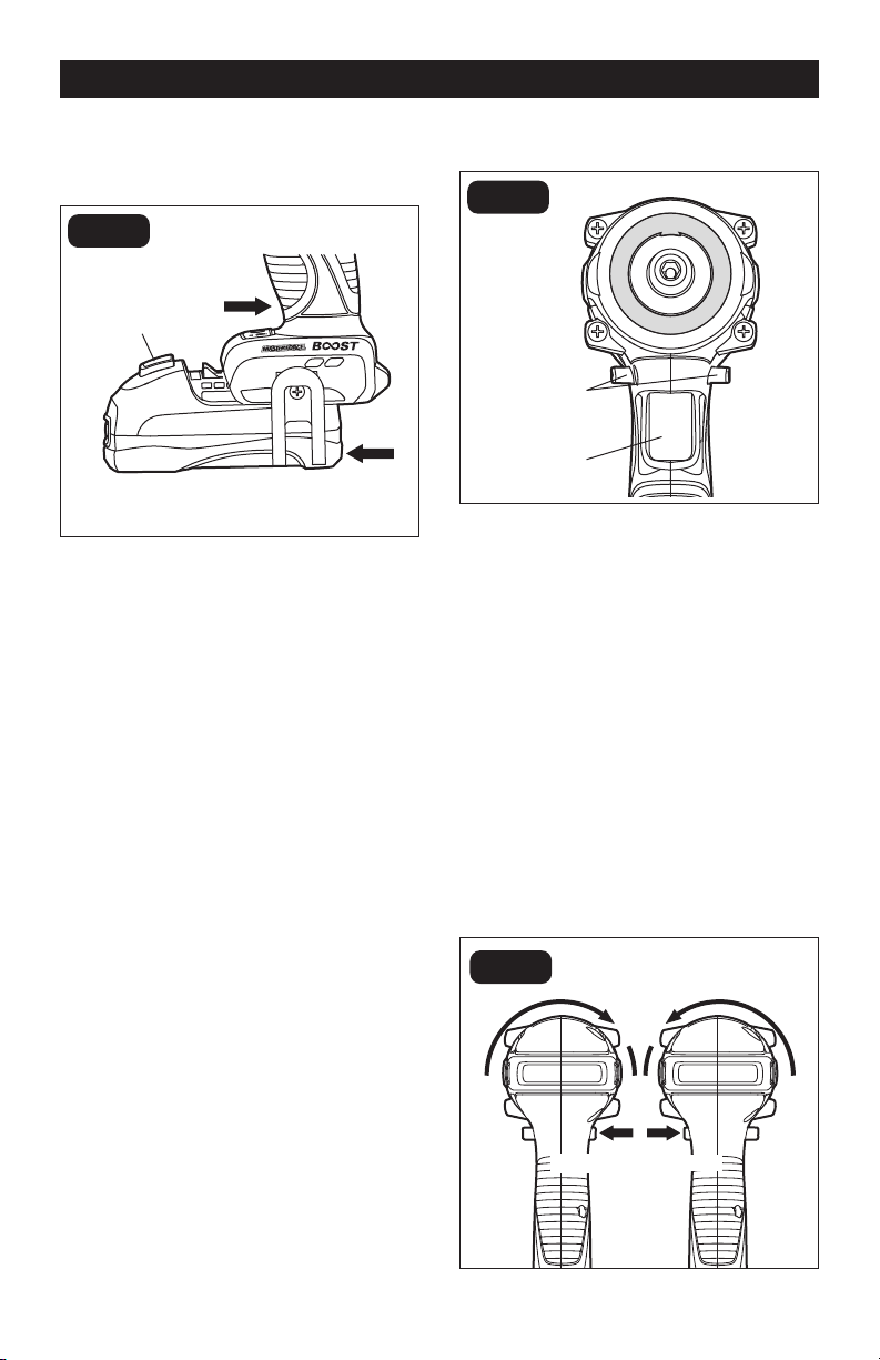
2 Ensure that the battery-release button
on the battery pack snaps into place
and the battery pack is secured to the
tool before beginning operation.
NOTICE: When placing the battery pack
on the tool, be sure that the raised rib on
the battery pack aligns with the groove on
the tool and the latches snap into place
properly. Improper assembly of the battery
pack can cause damage to internal com-
ponents.
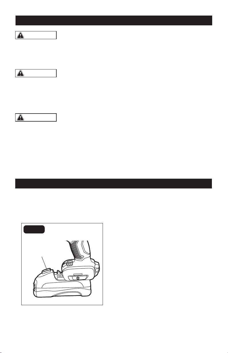
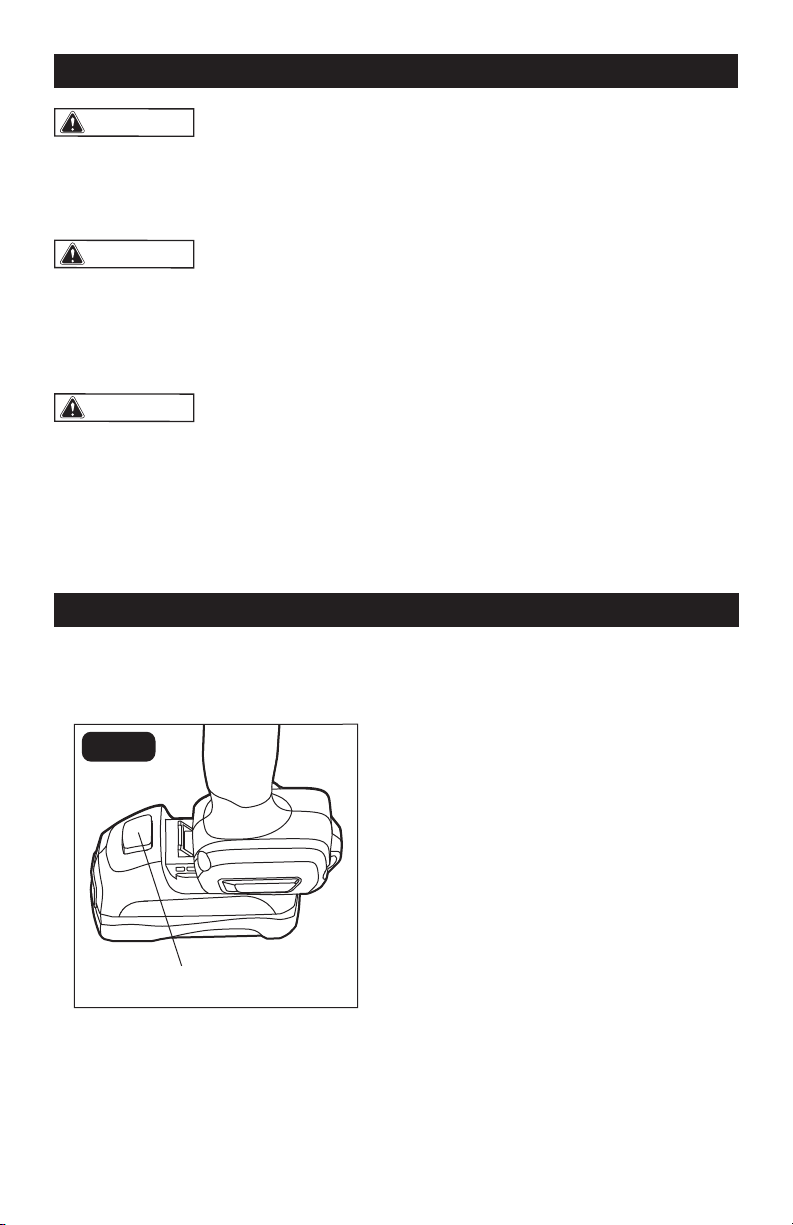
TO DETACH BATTERY
PACK (FIG.1)
1. Press the battery-release button to
release the battery pack.
2. Pull the battery pack to remove it from
the tool.
OPERATION
ASSEMBLY
CONTENTS
Cordless drill/driver, bit, belt clip, screw,
side handle, and instruction manual.
UNPACKING
1. Carefully remove the tool and any
accessories from the carton. Make sure
that all items listed in the packing list are
included.
2. Inspect the tool carefully to make sure
that no breakage or damage occurred
during shipping.
3. Do not discard the packing material
until you have carefully inspected and
satisfactorily operated the tool.
TO ATTACH BATTERY
PACK (FIG.1)
FIG. 1
Battery-Release
Button
1. Align the raised rib on the battery pack
with the grooves on the bottom of the
tool, then slide the battery pack onto the
tool.
WARNING:
If any part is broken or
missing, DO NOT attach the battery pack
or operate the tool until the broken or
missing part is replaced. Failure to do so
could result in possible serious injury.
WARNING:
Do not attempt to
modify this tool or create accessories not
recommended for use with this tool. Any
such alteration or modification is misuse
and could result in a hazardous condition
leading to possible serious injury.
WARNING:
Your tool should
never be connected to the battery pack
when you are assembling parts, making
adjustments, cleaning, or when it is not in
use. Disconnecting the tool will prevent
accidental starting, which could cause
serious personal injury.
Page 10
STORE THE BIT (FIG.3)
FIG. 3
Bit Holder
Your drill/driver is equipped with a bit holder
on the heel of the tool. After using the bit,
you can insert the bit into the bit holder for
convenient storage.
INSTALL/REMOVE THE SIDE
HANDLE (FIG.4)
FIG. 4
Side Handle
1. Align the side handle with either the left
or right mounting hole in the housing of
the tool.
2. Turn the side handle clockwise to
tighten the side handle.
3. Turn the side handle counterclockwise
to loosen and remove the side handle.
OPERATION
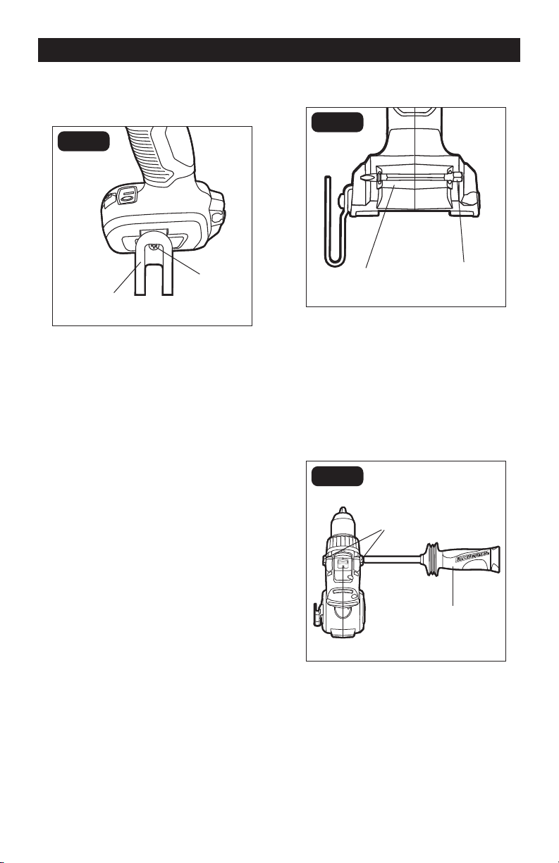
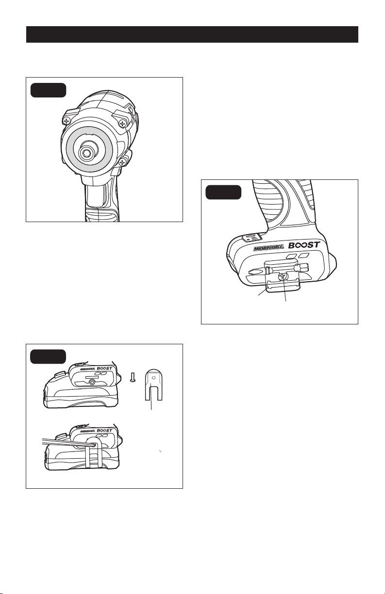
INSTALL THE BELT
CLIP (FIG.2)
FIG. 2
1. Align the rib of the clip with the hole on
the base of the drill/driver.
2. Insert the screw and tighten the screw
securely with a screwdriver. The belt clip
can be positioned on the left side of the
tool.
REMOVE THE BELT
CLIP (FIG.2)
1. Use a screwdriver to loosen the screw
that attaches the belt clip to the drill/
driver.
2. Remove the screw and the belt clip.
Bit
Mounting Holes
Screw
Belt Clip
Page 11
OPERATION
3. The variable-speed trigger switch
delivers higher speed with increased
trigger pressure and lower speed with
decreased trigger pressure.
WARNING:
Allow the motor to
come to a complete stop before setting
the drill/driver down.
ELECTRIC BRAKE
To stop the drill/driver, release the trigger
switch and allow the chuck to come to a
complete stop. The electric brake quickly
stops the chuck from rotating. This feature
engages automatically when the trigger
switch is released.
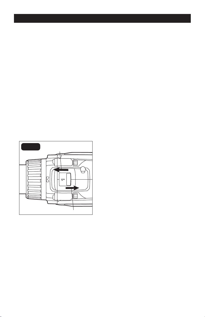
DIRECTION-OF-ROTATION SE-
LECTOR
(FORWARD/CENTERLOCK/
REVERSE) (FIG. 7)
FIG. 7
Reverse
The direction of bit rotation is reversible and
is controlled by a selector located above the
variable-speed trigger switch. With the drill/
driver held in normal operating position:
1. Position the direction-of-rotation
selector to the right of the tool for
reverse rotation.
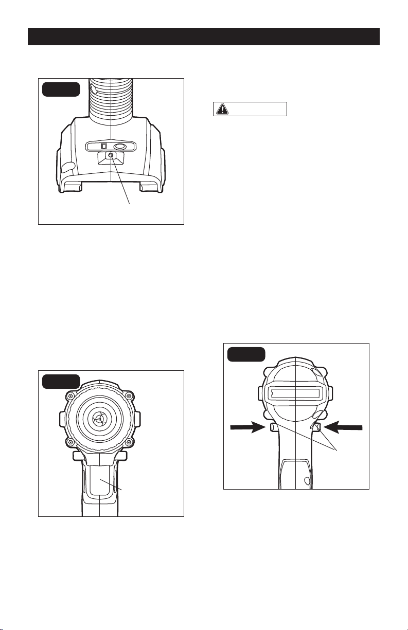
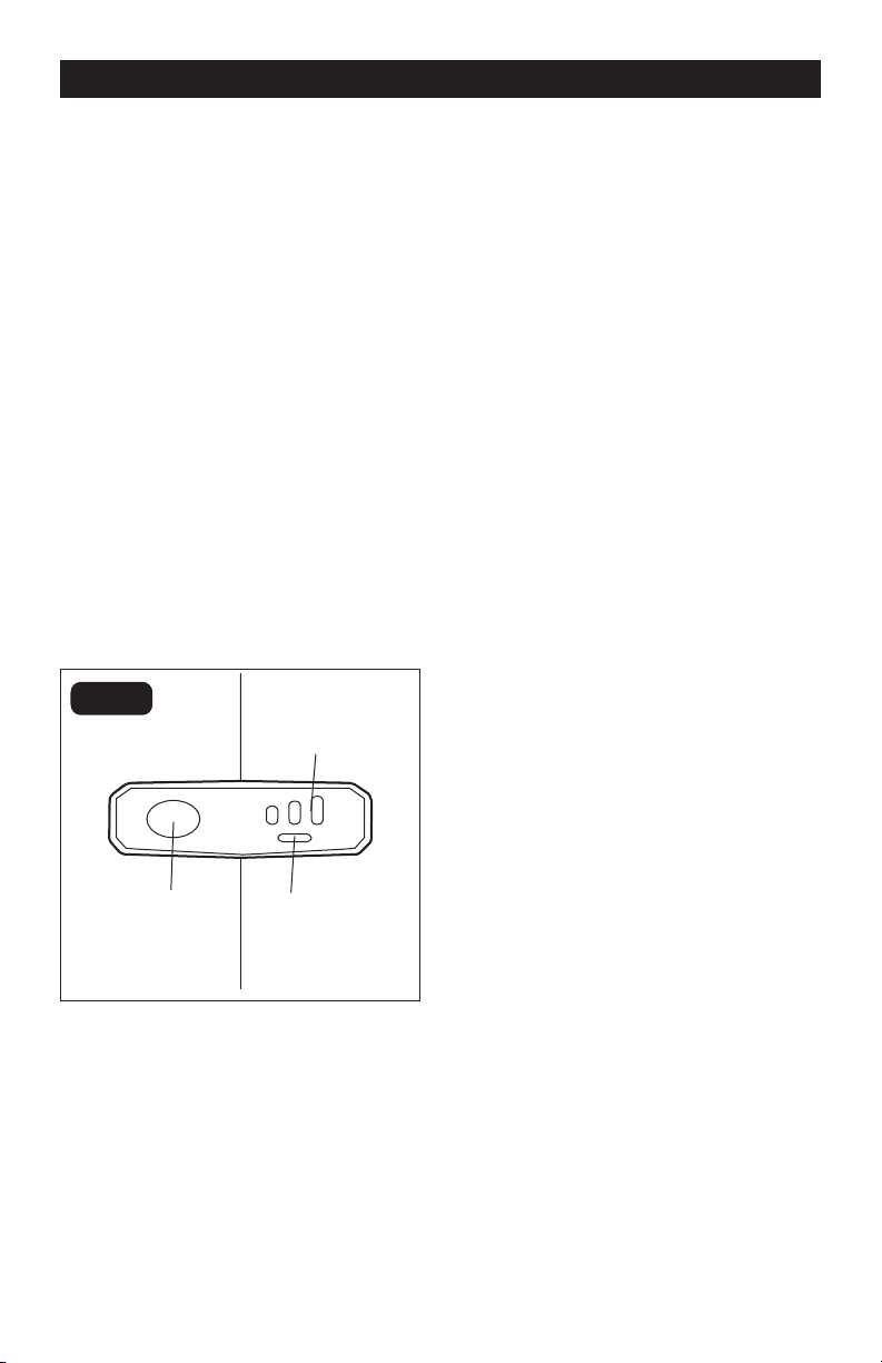
LED WORKLIGHT (FIG.5)
FIG. 5
The LED worklight, located on the base
of the drill/driver, will illuminate when the
trigger switch is depressed before the drill/
driver is running. This provides additional
light on the surface of the workpiece. The
light will automatically turn off within 10
seconds after trigger is released.
VARIABLE-SPEED TRIGGER
SWITCH (FIG. 6)
FIG. 6
1. To turn the drill/driver ON, press the
variable-speed trigger switch.
2. To turn the drill/driver OFF, release the
variable-speed trigger switch.
LED Worklight
Variable-Speed
Trigger Switch
Forward
Direction-
Of-Rotation
Selector
Page 12
OPERATION
2. Position the direction-of-rotation
selector to the left of the tool for forward
rotation.
3. Setting the direction-of-rotation selector
in the OFF (center-lock) position helps
reduce the possibility of accidental
starting when not in use.
NOTICE: To prevent gear damage, always
allow the drill/driver to come to a complete
stop before changing the direction of rota-
tion.
NOTICE: The drill/driver will not run unless
the direction-of-rotation selector is en-
gaged fully to the left or right.
TWO-SPEED GEARBOX
(FIG. 8)
FIG. 8
High
The drill/driver has a two-speed gearbox
for drilling or driving at either low or high
speeds. A slide switch is located on the
top of the drill/ driver to select either low or
high speed. The required speed is adjusted
depending on the material and the working
conditions.
Use low speed for high-power and high-
torque applications and high speed for fast
drilling or driving applications.
Low
When using drill/driver in the low-speed
range, the speed will decrease and the drill/
driver will have more power and torque.
Use low speed for starting holes without
a center punch, drilling metals or plastic,
drilling ceramics, or in applications requiring
a higher torque.
High speed is better for drilling wood and
wood composites.
NOTICE: Avoid running the drill/driver at
high speed for extended periods of time.
Running at high speed under constant us-
age may cause the drill/driver to become
overheated.
NOTICE: Make sure that the two-speed
gearbox switch is fully adjusted at the front
or the back position.
NOTICE: Never adjust the speed while the
tool is running. Failure to obey this caution
could result in serious damage to the drill/
driver.
Page 13
OPERATION
The torque clutch can be adjusted to any
of 24 different settings (23 driving and 1
drilling). The higher the torque setting,
the more force the drill/driver produces to
turn an object in either low or high rotation
speed.
When using the drill/driver for different
driving applications, increase or decrease
the torque in order to help prevent damage
to the screw heads, threads, workpiece, etc.
Adjust the torque by rotating the torque-
adjustment ring. The proper setting depends
on the job and the type of bit, fastener, and
material you will be using.
In general, use greater torque for larger
screws. If the torque is too high, the screws
may be damaged or broken. For delicate
operations, such as removing a partially
stripped screw, use a low torque setting. For
operations such as drilling into hardwood,
use a higher torque setting.
NOTICE: Do not change the torque setting
when the tool is running.
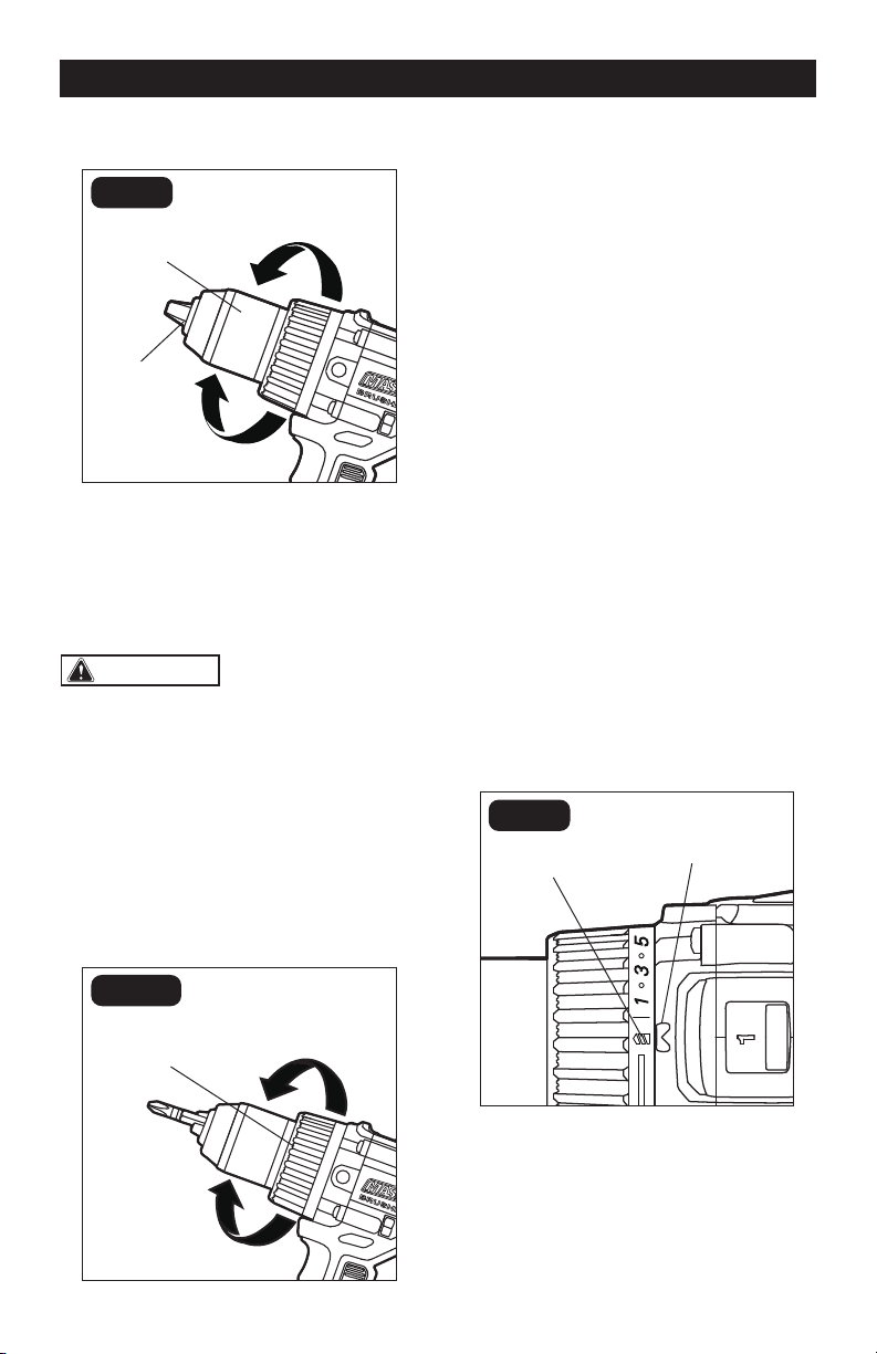
DRILL MODE (FIG. 11)
FIG. 11
Select the drill mode for drilling and other
heavy-duty applications.
To select drill mode, rotate the torque-
adjustment ring until the drill icon aligns with
the torque indicator.
KEYLESS CHUCK (FIG.9)
FIG. 9
Lock (Tighten)
The drill/driver has a keyless chuck to
tighten or release bits in the chuck jaws. The
arrows on the chuck indicate the direction in
which to rotate the chuck in order to LOCK
(tighten) or UNLOCK (release) the chuck
jaws on the bit.
WARNING:
Do not hold the chuck
with one hand and use the power of the
drill/driver to tighten the chuck jaws on
the drill bit. The chuck could slip in your
hand, or your hand could slip and come
in contact with the rotating bit. This could
cause an accident resulting in serious
personal injury.
ADJUST THE TORQUE (FIG. 10)
FIG. 10
Unlock (Release)
Chuck Jaws
Keyless Chuck
To Increase Torque
To Decrease Torque
Torque-Adjustment
Ring
Drill Icon
Torque Indicator
Page 14
INSTALL THE BIT (FIG.13)
FIG. 13
Unlock
(Release)
1. Remove the battery pack from the drill/
driver.
2. Open the chuck jaws until the opening is
slightly larger than the bit you intend to
use and raise the front of the drill/driver
slightly to keep the bit from falling out of
the chuck jaws.
3. Insert the bit into the chuck.
4. Rotate the chuck in the direction of the
arrow marked LOCK to close the chuck
jaws.
5. Tighten the chuck jaws securely on the
bit.
REMOVE THE BIT (FIG.13)
1. Remove the battery pack from the drill/
driver.
2. Open the chuck jaws.
3. Rotate the chuck in the direction of the
arrow marked UNLOCK to loosen the
chuck jaws.
4. Remove the bit.
OPERATION
IMPULSE MODE (FIG.12)
FIG. 12
1. Impulse mode creates a pulsating on-
off-on motor power cycle, which leads to
a short impulse of torque, together with
low speed, that can be more effective
than a pure rotational motion for certain
applications. The impulse mode can be
used to remove stubborn screws and
prevent the bit tip from walking when
drilling into smooth surfaces, such as
ceramic tiles and steel pipes.
2. Attach the battery to the tool.
3. Turn the direction-of-rotation selector
fully to the left or right and then press the
trigger switch to shine the LED worklight.
4. If the impulse indicator is off, you can
press the impulse button to turn on
the impulse indicator. If the impulse
indicator is on, it indicates that the
impulse mode has been turned.
WARNING:
Do not work for long
periods with the impulse mode activated
as the motor can be overheated.
NOTICE: The impulse mode has a memory
function. If the impulse mode is activated
and not turned off, you can continue to
use the mode directly next time.
NOTICE: With the impulse mode on, the
impulse indicator will be automatically turn
off about 1 minute after the trigger switch
is released.
Impulse
Indicator
Impulse
Button
Bit
Lock
(Tighten)
Keyless Chuck
Chuck Jaws

Page 15
DRILLING IN WOOD
For maximum performance, use high-
speed-steel (available separately) or brad-
point bits (available separately) for wood
drilling.
1. When drilling “through” holes, place a
block of wood behind the workpiece to
prevent ragged or splintered edges on
the back side of the hole.
2. Begin drilling at a very low speed to
prevent the bit from slipping off the
starting point.
3. Increase speed as the drill bit bites into
the material.
DRILLING IN METAL
For maximum performance, use high-
speed-steel bits (available separately) for
metal or steel drilling. It’s recommended to
use the impulse mode to drill into the steel
pipes.
1. When drilling metals, use light oil on
the drill bit to keep it from overheating.
The oil will prolong the life of the bit and
increase the drilling action.
2. Begin drilling at a very low speed to
prevent the bit from slipping off the
starting point.
3. Maintain a speed and a pressure that
allow cutting without overheating the
bit. Applying too much pressure will:
• Overheat the drill/driver
• Wear the bearings
• Bend or burn bits
• Produce off-center or irregularly shaped
holes
OPERATION
WARNING:
Make sure to insert
the bit straight into the chuck jaws. Do
not insert the bit into the chuck jaws at an
angle and then tighten. This could cause
the bit to be thrown from the drill/driver,
resulting in possibly serious personal
injury or damage to the chuck.
WARNING:
Use protective gloves
when removing the bit from the tool, or
first allow the bit to cool down. The bit
may be hot after prolonged use.
DRILLING
1. Check that the direction-of-rotation
selector is at the forward setting.
2. Secure the material to be drilled in a vise
or with clamps to keep it from turning as
the drill bit rotates.
3. Hold the drill/driver firmly and place the
bit at the point to be drilled.
4. Depress the variable-speed trigger
switch to start the drill/driver.
5. Move the drill bit into the workpiece,
applying only enough pressure to keep
the bit drilling. Do not force the drill or
apply side pressure to elongate a hole.
Let the tool do the work.
6. When drilling hard and smooth surfaces,
use a center punch to mark the desired
location of the hole. This will prevent the
drill bit from slipping off-center as the
hole is started.
7. When drilling metals, use light oil on
the drill bit to keep it from overheating.
The oil will prolong the life of the bit and
increase the drilling action.
8. If the bit jams in the workpiece or if the
drill stalls, stop the tool immediately.
Remove the bit from the workpiece and
determine the reason for jamming.

Page 16
OPERATION
DRILLING IN CERAMIC TILES
For maximum performance, use carbide-
tipped masonry bits (available separately)
for ceramic tile drilling. It’s recommended
to use the impulse mode to drill into the
ceramic tiles.
1. Use just enough force on the drill to
keep it from bouncing excessively. Too
much force will cause slower drilling
speeds, overheating and a lower drilling
rate.
2. Do not exert side pressure on the bit
when drilling, as this will cause clogging
of the bit flutes and a slower drilling
speed.
3. If the drill speed starts to drop off when
drilling deep holes, pull the bit partially
out of the hole with the tool still running
to help clear debris from the hole.
SCREWDRIVER OPERATION
1. Select the desired speed/torque range
to match the planned operation.
2. Attach the desired fastener accessory
into the chuck.
3. Make a few practice runs in a scrap
piece before working.
WARNING:
When servicing, use
only identical replacement parts. Use of
any other parts may create a hazard or
cause product damage.
WARNING:
To avoid serious
personal injury, always remove the battery
pack from the product when cleaning or
performing any maintenance.
WARNING:
Avoid using solvents
when cleaning plastic parts. Most plastics
are susceptible to damage from various
types of commercial solvents and may be
damaged by their use. Use a clean cloth
to remove dirt, dust, oil, grease, etc.
MAINTENANCE
WARNING:
Using compressed
air may be the most effective cleaning
method. Always wear safety goggles
when cleaning tools with compressed air.

Page 17
TROUBLESHOOTING
PROBLEM POSSIBLE CAUSE SOLUTION
The drill/driver does not work. The battery is depleted. Charge the battery.
The bit cannot be installed.
The chuck sleeve is not
released.
Release the chuck sleeve.
The bit does not fit the
sleeve.
Use a suitable bit.
Motor is overheating
The cooling vents may be
obstructed.
Clean and clear the vents.
Do not cover the vents with
your hand during operation

SAVE YOUR RECEIPTS
THIS WARRANTY IS VOID WITHOUT THEM
1/2" BRUSHLESS DRILL/DRIVER
WARRANTY
90-DAY MONEY BACK GUARANTEE:
This MASTERFORCE® brand power tool carries our 90-DAY Money Back
Guarantee. If you are not completely satisfied with your MASTERFORCE® brand
power tool for any reason within ninety (90) days from the date of purchase, return
the tool with your original receipt to any MENARDS® retail store, and we will provide
you a refund – no questions asked.
3-YEAR LIMITED WARRANTY:
This MASTERFORCE® brand power tool carries our famous No Hassle 3-Year Limited
Warranty to the original purchaser. If, during normal use, this MASTERFORCE® power
tool breaks or fails due to a defect in material or workmanship within three (3) years
from the date of original purchase, simply bring this tool with the original sales receipt
back to your nearest MENARDS® retail store. At its discretion, MASTERFORCE®
agrees to have the tool or any defective part(s) repaired or replaced with the same or
similar MASTERFORCE® product or part free of charge, within the stated warranty
period, when returned by the original purchaser with original sales receipt. Not
withstanding the foregoing, this limited warranty does not cover any damage that
has resulted from abuse or misuse of the Merchandise. This warranty: (1) excludes
expendable parts including but not limited to blades, brushes, belts, bits, light bulbs,
and/or batteries; (2) shall be void if this tool is used for commercial and/or rental
purposes; and (3) does not cover any losses, injuries to persons/property or costs. This
warranty does give you specific legal rights and you may have other rights, which vary
from state to state. Be careful, tools are dangerous if improperly used or maintained.
Seller’s employees are not qualified to advise you on the use of this Merchandise.
Any oral representation(s) made will not be binding on seller or its employees. The
rights under this limited warranty are to the original purchaser of the Merchandise
and may not be transferred to any subsequent owner. This limited warranty is in lieu
of all warranties, expressed or implied including warranties or merchantability and
fitness for a particular purpose. Seller shall not be liable for any special, incidental, or
consequential damages. The sole exclusive remedy against the seller will be for the
replacement of any defects as provided herein, as long as the seller is willing or able
to replace this product or is willing to refund the purchase price as provided above.
For insurance purposes, seller is not allowed to demonstrate any of these power tools
for you.
For questions / comments, technical assistance or repair parts – Please Call Toll
Free at: 1-866-917-4374. (M-F 8:30am-5:00pm Est.)

05/2020
© 2020 Menard, Inc., Eau Claire, WI 54703
241-0355
1/4” Impact Driver
OPERATOR’S MANUAL
CAUTION:
To Reduce the Risk of Injury, User Must
Read and Understand the Operator’s Manual. Save These
Instructions For Future Reference.
For questions / comments, technical assistance or repair parts –
Please Call Toll Free: 1-866-917-4374 (M-F 8:30am-5:00pm EST).

TABLE OF CONTENTS
Safety Symbols ......................................................... Page 2
Safety Instructions ...................................................... Page 3
Overview/Specications ................................................. Page 7
Assembly ............................................................. Page 8
Operation ............................................................. Page 9
Maintenance .......................................................... Page 13
Troubleshooting ....................................................... Page 14
Warranty ............................................................. Page 15
Page 2
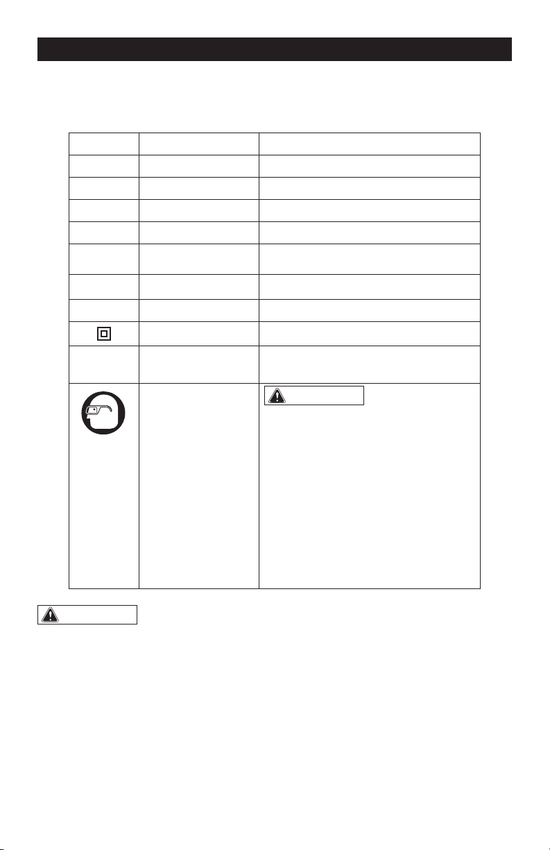
SAFETY SYMBOLS
Some of these following symbols may be used on this tool. Please study them and learn their
meaning. Proper interpretation of these symbols will allow you to operate the tool better and
more safely.
Symbol
Name
Designation / Explanation
V Volts Voltage
A Amperes Current
Hz Hertz Frequency (cycles per second)
W Watts Power
∿
Alternating current Type of current
�
Direct current Type or characteristic of current
n
o
No-load speed Rotational speed at no load
Class II construction Double insulated construction
.../min Per minute
Revolutions, strokes, surface speed
orbits, etc., per minute
Wear safety goggles
WARNING:
The operation of any
power tool can result in foreign objects
being thrown into your eyes, which can
result in severe eye damage. Before
beginning power tool operation, always
wear safety goggles or safety glasses
with side shields and a full-face shield
when needed. We recommend a Wide
Vision Safety Mask for use over eye-
glasses or standard safety glasses with
side shields. Always use eye protection
which is marked to comply with
ANSI Z87.1.
WARNING:
To ensure safety and reliability, all repairs should be performed by a
qualified service technician.
Page 3
SAFETY INSTRUCTIONS
The purpose of safety symbols is to attract your attention to possible dangers. The safety
symbols, and the explanations with them, deserve your careful attention and understand-
ing. The symbol warnings do not, by themselves, eliminate any danger. The instructions and
warnings they give are no substitutes for proper accident prevention measures.
WARNING:
Be sure to read and understand all safety instructions in this manual,
including all safety alert symbols such as “DANGER”, “WARNING” and “CAUTION” before
using this tool. Failure to following all instructions listed below may result in electric
shock, fire, and/or serious personal injury.
SYMBOL MEANING
SAFETY ALERT SYMBOL: Indicates DANGER, WARNING, OR CAUTION.
May be used in conjunction with other symbols or pictographs.
DANGER:
Indicates an imminently hazardous situation, which, if not avoided, will
result in death or serious injury.
WARNING:
Indicates a potentially hazardous situation, which, if not avoided,
could result in death or serious injury.
CAUTION:
Indicates a potentially hazardous situation, which, if not avoided, could
result in minor or moderate injury.
NOTICE: (Without Safety Alert Symbol) Indicates a situation that may result in property
damage.
SAVE THESE INSTRUCTIONS!

Page 4
SAFETY INSTRUCTIONS
GENERAL POWER TOOL SAFETY
WARNINGS
WARNING:
Read all safety
warnings, instruction, illustrations and
specifications provided with this power
tool.
Failure to follow all instructions listed below
may result in electric shock, re and/or seri-
ous injury.
Save all warnings and instructions for future
reference.
The term “power tool” in the warnings refers
to your mains-operated (corded) power tool
or battery-operated (cordless) power tool.
WORK AREA SAFETY
a) Keep work area clean and well lit.
Cluttered or dark areas invite accidents.
b) Do not operate power tools in explosive
atmospheres, such as in the presence of
flammable liquids, gases or dust. Power
tools create sparks which may ignite the
dust or fumes.
c) Keep children and bystanders away
while operating a power tool. Distractions
can cause you to lose control.
ELECTRICAL SAFETY
a) Power tool plugs must match the
outlet. Never modify the plug in any way.
Do not use any adapter plugs with earthed
(grounded) power tools. Unmodied plugs
and matching outlets will reduce risk of
electric shock.
b) Avoid body contact with earthed
or grounded surfaces, such as pipes,
radiators, ranges and refrigerators. There
is an increased risk of electric shock if your
body is earthed or grounded.
c) Do not expose power tools to rain or
wet conditions. Water entering a power
tool will increase the risk of electric shock.
d) Do not abuse the cord. Never use the
cord for carrying, pulling or unplugging
the power tool. Keep cord away from
heat, oil, sharp edges or moving parts.
Damaged or entangled cords increase the
risk of electric shock.
e) When operating a power tool outdoors,
use an extension cord suitable for outdoor
use. Use of a cord suitable for outdoor use
reduces the risk of electric shock.
f) If operating a power tool in a damp
location is unavoidable, use a ground fault
circuit interrupter (GFCI) protected supply.
Use of an GFCI reduces the risk of electric
shock.
PERSONAL SAFETY
a) Stay alert, watch what you are doing
and use common sense when operating a
power tool. Do not use a power tool while
you are tired or under the influence of
drugs, alcohol or medication. A moment of
inattention while operating power tools may
result in serious personal injury.
b) Use personal protective equipment.
Always wear eye protection. Protective
equipment such as a dust mask, non-skid
safety shoes, hard hat or hearing protection
used for appropriate conditions will reduce
personal injuries.
c) Prevent unintentional starting. Ensure
the switch is in the off-position before
connecting to power source and/or battery
pack, picking up or carrying the tool.
Carrying power tools with your nger on the
switch or energizing power tools that have
the switch on invites accidents.
d) Remove any adjusting key or wrench
before turning the power tool on. A wrench
or a key left attached to a rotating part of
the power tool may result in personal injury.
e) Do not overreach. Keep proper
footing and balance at all times. This
enables better control of the power tool in
unexpected situations.
f) Dress properly. Do not wear loose
clothing or jewelry. Keep your hair and

Page 5
SAFETY INSTRUCTIONS
clothing away from moving parts. Loose
clothes, jewelry or long hair can be caught
in moving parts.
g) If devices are provided for the
connection of dust extraction and
collection facilities, ensure these are
connected and properly used. Use of dust
collection can reduce dust-related hazards.
h) Do not let familiarity gained from
frequent use of tools allow you to become
complacent and ignore tool safety
principles. A careless action can cause
severe injury within a fraction of a second.
POWER TOOL USE AND CARE
a) Do not force the power tool. Use the
correct power tool for your application. The
correct power tool will do the job better and
safer at the rate for which it was designed.
b) Do not use the power tool if the switch
does not turn it on and off. Any power tool
that cannot be controlled with the switch is
dangerous and must be repaired.
c) Disconnect the plug from the power
source and/or remove the battery pack,
if detachable, from the power tool before
making any adjustments, changing
accessories, or storing power tools. Such
preventive safety measures reduce the risk
of starting the power tool accidentally.
d) Store idle power tools out of the reach
of children and do not allow persons
unfamiliar with the power tool or these
instructions to operate the power tool.
Power tools are dangerous in the hands of
untrained users.
e) Maintain power tools and accessories.
Check for misalignment or binding of
moving parts, breakage of parts and
any other condition that may affect the
power tool’s operation. If damaged, have
the power tool repaired before use. Many
accidents are caused by poorly maintained
power tools.
f) Keep cutting tools sharp and clean.
Properly maintained cutting tools with sharp
cutting edges are less likely to bind and are
easier to control.
g) Use the power tool, accessories
and tool bits etc. in accordance with
these instructions, taking into account
the working conditions and the work to
be performed. Use of the power tool for
operations different from those intended
could result in a hazardous situation.
h) Keep handles and grasping surfaces dry,
clean and free from oil and grease. Slippery
handles and grasping surfaces do not allow
for safe handling and control of the tool in
unexpected situations.
SERVICE
a) Have your power tool serviced by a
qualified repair person using only identical
replacement parts. This will ensure that the
safety of the power tool is maintained.
SPECIFIC SAFETY WARNINGS
a) Hold power tools by insulated gripping
surfaces when performing an operation
where the cutting tool may contact hidden
wiring. Contact with a” live” wire will make
exposed metal parts of the tool live and
shock the operator.
b) Take protective measures when
dust can develop during working that
is harmful to one’s health, combustible
or explosive. Example: Some dusts are
regarded as carcinogenic. Wear a dust
mask and work with dust/chip extraction
when connectable.
c) Secure the workpiece. A workpiece
clamped with clamping devices or in a vice
is held more secure than by hand.
d) To reduce the risk of electric shock or
damage to the charger and battery, use
only the batteries and charger listed.

Page 6
SAFETY INSTRUCTIONS
Battery pack Charger
252-8027
252-8029
252-8030
252-8031
252-8034
252-8035
252-8003
252-8005
252-8007
252-8025
252-8026
252-8037
WARNING:
Some dust created by
power sanding, sawing, grinding, drilling
and other construction activities contains
chemicals known to the state of California
to cause cancer, birth defects or other
reproductive harm. Some examples of
these chemicals are:
• Lead from lead-based paints
• Crystalline silica from bricks and cement
and other masonry products, and
• Arsenic and chromium from chemically-
treated lumber.
Your risk from these exposures varies,
depending on how often you do this type
of work. To reduce your exposure to these
chemicals: work in a well ventilated area,
and work with approved safety equipment,
such as those dust masks that are specially
designed to lter out microscopic particles.
Page 7
OVERVIEW
SPECIFICATIONS
No-load Speed I: 0-1,100 RPM
II: 0-2,000 RPM
III: 0-3,100 RPM
Impact Rate I: 0-1,250 BPM
II: 0-2,650 BPM
III: 0-3,500BPM
Torque I: 9,50 in.lb
II: 1,450 in.lb
III: 2,000 in.lb
Driver 1/4” Hex
Weight 2 lb. 14 oz (1.3 kg)
LED Worklight Ring
Mode-selector
Trigger Switch
Chuck
Direction-of-rotation
Selector
Belt Clip

Page 8
WARNING:
If any part is broken or
missing, DO NOT attach the battery pack
or operate the tool until the broken or
missing part is replaced. Failure to do so
could result in possible serious injury.
WARNING:
Do not attempt to
modify this tool or create accessories not
recommended for use with this tool. Any
such alteration or modification is misuse
and could result in a hazardous condition
leading to possible serious injury.
WARNING:
Your tool should
never be connected to the battery pack
when you are assembling parts, making
adjustments, installing or removing
bits, cleaning, or when it is not in use.
Disconnecting the tool will prevent
accidental starting, which could cause
serious personal injury.
ASSEMBLY
CONTENTS
Cordless impact driver, bit holder, belt clip,bit
and instruction manual.
UNPACKING
1. Carefully remove the tool and any
accessories from the carton. Make sure
that all items listed in the packing list are
included.
2. Inspect the tool carefully to make sure
that no breakage or damage occurred
during shipping.
3. Do not discard the packing material
until you have carefully inspected and
satisfactorily operated the blower.
Page 9
TRIGGER SWITCH (FIG.2)
To turn the impact driver on, depress the
trigger switch.
To turn it off, release the trigger switch.
VARIABLE SPEED
The variable-speed trigger switch delivers
higher speed with increased trigger pressure
and lower speed with decreased trigger
pressure.
DIRECTION-OF-ROTATION SE-
LECTOR (FORWARD/CENTER-
LOCK/REVERSE) (FIG.3)
OPERATION
Direction-of-
rotation Selector
Trigger Switch
FIG. 2
Reverse
Forward
FIG. 3
TO ATTACH BATTERY PACK
(FIG. 1)
1. Make sure that the tool is switched off.
2. Align the raised rib on the battery pack
with the grooves on the bottom of the
impact driver, and then slide the battery
pack onto the tool.
NOTICE: Make sure that the latch on the
battery pack snaps into place and the bat-
tery pack is secured to the tool before op-
eration.
TO DETACH BATTERY PACK
(FIG. 1)
1. Make sure that the tool is switched off.
2. Depress the battery-release button
located on the front of the battery pack
to release the battery pack.
3. Pull the battery pack out and remove it
from the tool.
Attach
Battery-release
Button
Detach
FIG. 1
Page 10
The direction of rotation is reversible and is
controlled by a selector located above the
trigger switch. With the impact driver held
in normal operating position: position the
direction-of-rotation selector to the left of
the tool for forward rotation; position the
direction-of-rotation selector to the right
of the tool for reverse rotation. Setting the
switch in the OFF (center-lock) position
helps to reduce the possibility of accidental
starting when not in use.
NOTICE: To prevent gear damage, always
allow the impact driver to come to a com-
plete stop before changing the direction of
rotation.
NOTICE: The impact driver will not run un-
less the direction of the rotation selector is
engaged fully to the left or right.
MODE SELECTOR (FIG.4)
NOTICE: The impact driver is designed
with 3-speed and auto-stop functions;
these functions are available only when the
tool is operating in forward rotation.
NOTICE: The mode can only be changed
when the mode-indicator light is on. The
mode-indicator light will be off automati-
cally in about one minute.
1. Attach the battery pack to the impact
driver.
2. Position the direction-of-rotation
selector to the left of the tool for forward
rotation, and press the trigger switch to
turn on the mode-indicator light.
3. Press the mode selector to change the
speed: press once for low, press twice
for medium, and press a third time for
high.
4. To make the Auto-stop function
available, press and hold the mode
selector for three seconds: the auto-
stop indicator will shine. When a bolt/
nut is sufciently tightened, the tool
will automatically stop the impact
and rotation after approximately one
second.
5. To turn off the auto-stop function, press
and hold the mode selector for three
seconds again. The auto-stop indicator
is will turn off.
ELECTRIC BRAKE
The impact driver is equipped with an
electric brake. When the trigger switch
is released, the electric brake engages
automatically to quickly stop the rotation.
OPERATION
L
AUTOSTOP
H
Mode Selector
Mode Indicator
Auto-stop
Indicator
FIG. 4
Page 11
REMOVING THE BELT CLIP
1. Remove the battery from the tool.
2. Use a screwdriver to loosen the screw
that attaches the belt clip to the driver.
3. Remove the screw and the belt clip.
TO INSTALL THE BIT HOLDER
(FIG.7):
1. Remove the battery from the tool.
2. Align the rib of the bit holder with the
hole in the base of the impact driver.
3. Insert the screw (included) and securely
tighten the screw with a screwdriver
(not included). The bit holder can be
positioned on either side of the tool.
To remove the bit holder:
1. Remove the battery from the tool.
2. Use a screwdriver to loosen the screw
that attaches the bit holder to the
impact driver.
3. Remove the screw and the bit holder.
OPERATION
Bit Holder
Screw
FIG. 7
LED WORKLIGHT RING (FIG.5)
The LED worklight rings, located around
the shaft of the impact driver, will illuminate
when the trigger switch is depressed. This
provides additional light on the surface of the
workpiece for operation in lower-light areas.
The light will automatically turn off within 10
seconds after the trigger is released.
INSTALLING THE BELT CLIP
(FIG.6)
1. Remove the battery from the tool.
2. Align the rib of the belt clip with the hole
on the base of the driver.
3. Insert the screw and securely tighten
the screw with a screwdriver.
Belt Clip
FIG. 6
FIG. 5
Page 12
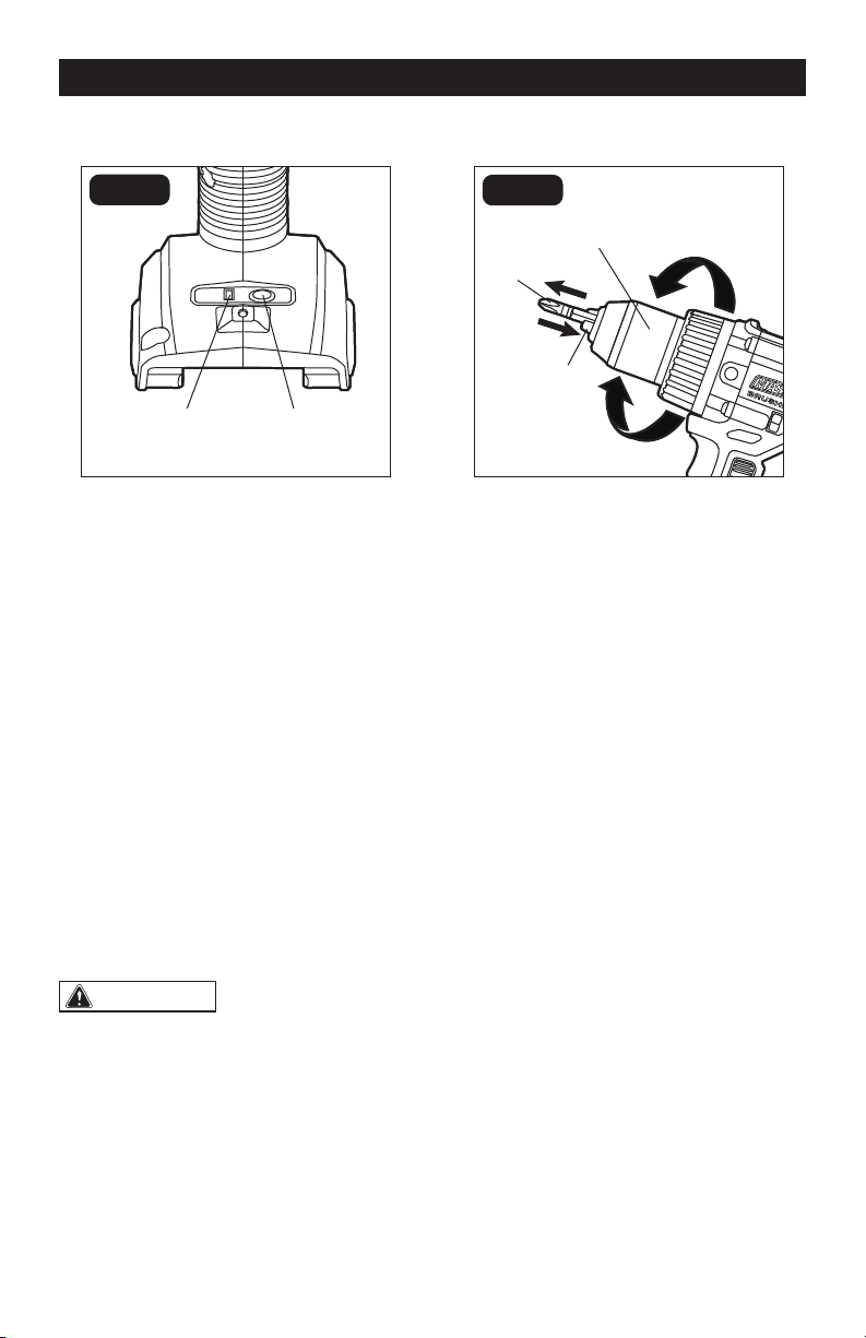
INSTALLING BITS (FIG.8)
1. Lock the trigger switch on the impact
driver by placing the direction-of-
rotation selector in the center position.
2. Insert the bit into the chuck. You will
hear a “click” to indicate that the bit is
securely installed in place.
3. Pull on the bit to check if it installed
securely.
REMOVING BITS
1. Lock the trigger switch on the impact
driver by placing the direction-of-
rotation selector in the center position.
2. Pull the sleeve towards the front of the
tool.
3. The bit should pop out from the chuck
automatically, if not, simply pull out the
bit.
TIGHTENING AND LOOSENING
SCREWS
1. Install the correct bit.
2. Apply just enough pressure to keep the
bit engaged on the screw.
3. Apply minimal pressure to the trigger
switch initially. Increase the speed only
when full control can be maintained.
TIGHTENING AND LOOSENING
NUTS AND BOLTS
Variable speed control must be used with
caution for driving nuts and bolts with
socket set attachments. The best technique
is to start slowly, increasing speed as the
nut or bolt runs down. Set the nut or bolt
snugly by slowing the tool to a stop. If this
procedure is not followed, the tool will have
a tendency to torque or twist in your hands
when the nut or bolt seats.
OPERATION
Sleeve
FIG. 8

Page 13
WARNING:
Always wear safety
goggles or safety glasses with side shields
during power tool operations, or when
blowing dust. If operation is dusty, also
wear a dust mask.
WARNING:
Do not at any time allow
brake fluids, gasoline, petroleum-based
products, penetrating oils, etc. to come in
contact with plastic parts. Chemicals can
damage, weaken or destroy plastic, which
may result in serious personal injury.
MAINTENANCE
The tool may be cleaned most effectively
with compressed dry air. Always wear
safety goggles when cleaning tools with
compressed air.
Avoid using solvents when cleaning plastic
parts. Most plastics are susceptible to
damage from various types of commercial
solvents and may be damaged by their use.
Use a clean cloth to remove dirt, dust, oil,
grease, etc.
BEFORE EACH USE
1. Check for damaged, missing, or worn
parts.
2. Check for loose screws, misalignment
or binding of moving parts, or any other
condition that may affect the operation.
3. If abnormal vibration or noise occurs,
turn the tool off immediately and have
the problem corrected before further
use.
MAINTENANCE

Page 14
TROUBLESHOOTING
PROBLEM CAUSE SOLUTION
The impact driver does
not work.
The battery pack is depleted. Charge the battery pack.
The battery pack or impact
driver is too hot.
Turn off the impact driver and
allow the impact driver and
battery pack to cool.

SAVE YOUR RECEIPTS
THIS WARRANTY IS VOID WITHOUT THEM
1/4” Impact Driver
WARRANTY
90-DAY MONEY BACK GUARANTEE:
This MASTERFORCE® brand power tool carries our 90-DAY Money Back
Guarantee. If you are not completely satised with your MASTERFORCE® brand
power tool for any reason within ninety (90) days from the date of purchase, return
the tool with your original receipt to any MENARDS® retail store, and we will provide
you a refund – no questions asked.
3-YEAR LIMITED WARRANTY:
This MASTERFORCE® brand power tool carries our famous No Hassle 3-Year Limited
Warranty to the original purchaser. If, during normal use, this MASTERFORCE® power
tool breaks or fails due to a defect in material or workmanship within three (3) years
from the date of original purchase, simply bring this tool with the original sales receipt
back to your nearest MENARDS® retail store. At its discretion, MASTERFORCE®
agrees to have the tool or any defective part(s) repaired or replaced with the same or
similar MASTERFORCE® product or part free of charge, within the stated warranty
period, when returned by the original purchaser with original sales receipt. Not
withstanding the foregoing, this limited warranty does not cover any damage that
has resulted from abuse or misuse of the Merchandise. This warranty: (1) excludes
expendable parts including but not limited to blades, brushes, belts, bits, light bulbs,
and/or batteries; (2) shall be void if this tool is used for commercial and/or rental
purposes; and (3) does not cover any losses, injuries to persons/property or costs. This
warranty does give you specic legal rights and you may have other rights, which vary
from state to state. Be careful, tools are dangerous if improperly used or maintained.
Seller’s employees are not qualied to advise you on the use of this Merchandise.
Any oral representation(s) made will not be binding on seller or its employees. The
rights under this limited warranty are to the original purchaser of the Merchandise
and may not be transferred to any subsequent owner. This limited warranty is in lieu
of all warranties, expressed or implied including warranties or merchantability and
tness for a particular purpose. Seller shall not be liable for any special, incidental, or
consequential damages. The sole exclusive remedy against the seller will be for the
replacement of any defects as provided herein, as long as the seller is willing or able
to replace this product or is willing to refund the purchase price as provided above.
For insurance purposes, seller is not allowed to demonstrate any of these power tools
for you.
For questions / comments, technical assistance or repair parts –
Please call toll free: 1-866-917-4374 (M-F 8:30am – 5:00pm EST).

11/2020
© 2020 Menard, Inc., Eau Claire, WI 54703
241-0448
COMPACT
RECIPROCATING SAW
For questions / comments, technical assistance or repair parts –
Please Call Toll Free: 1-866-917-4374 (M-F 8:30am-5:00pm EST).
OPERATOR’S MANUAL
CAUTION:
To Reduce The Risk Of Injury, User Must Read And
Understand Operator’s Manual. Save These Instructions For Future
Reference.

TABLE OF CONTENTS
Safety Symbols ......................................................... Page 2
Safety Instructions ...................................................... Page 3
Overview/Specifications ................................................. Page 7
Assembly ............................................................. Page 8
Operation ............................................................. Page 8
Maintenance .......................................................... Page 12
Troubleshooting ....................................................... Page 12
Warranty ............................................................. Page 14

Page 2
SAFETY SYMBOLS
Some of these following symbols may be used on this tool. Please study them and learn their
meaning. Proper interpretation of these symbols will allow you to operate the tool better and
more safely.
WARNING:
To ensure safety and reliability, all repairs should be performed by a
qualied service technician.
Symbol
Name
Designation / Explanation
V Volts Voltage
A Amps Current
Hz Hertz Frequency (cycles per second)
W Watts Power
lbs Pounds Weight
n
o
No-load speed Rotational speed at no load
SPM Strokes per Minute Unit of speed
�
or d.c
Direct current Type of characteristic of current
Read instruction
manual
To reduce the risk of injury, user must
read instruction manual.

Page 3
The purpose of safety symbols is to attract your attention to possible dangers. The
safety symbols, and the explanations with them, deserve your careful attention and
understanding. The symbol warnings do not, by themselves, eliminate any danger. The
instructions and warnings they give are no substitutes for proper accident prevention
measures.
WARNING:
Be sure to read and understand all safety instructions in this manual,
including all safety alert symbols such as “DANGER,” “WARNING,” and “CAUTION”
before using this tool. Failure to follow all instructions listed below may result in electric
shock, re, and/or serious personal injury.
SYMBOL MEANING
SAFETY ALERT SYMBOL: Indicates DANGER, WARNING, OR CAUTION.
May be used in conjunction with other symbols or pictographs.
DANGER:
Indicates an imminently hazardous situation, which, if not avoided,
will result in death or serious injury.
WARNING:
Indicates a potentially hazardous situation, which, if not avoided,
could result in death or serious injury.
CAUTION:
Indicates a potentially hazardous situation, which, if not avoided,
could result in minor or moderate injury.
NOTICE:
(Without Safety Alert Symbol) Indicates a situation that may result in property
damage.
SAVE THESE INSTRUCTIONS!
SAFETY INSTRUCTIONS

Page 4
GENERAL POWER TOOL
SAFETY WARNINGS
WARNING:
Read all safety
warnings, instructions, illustrations and
specications provided with this power
tool. Failure to follow all instructions listed
below may result in electric shock, fire and/or
serious injury.
Save all warnings and instructions for
future reference.
The term “power tool” in the warnings refers
to your mains-operated (corded) power tool
or battery-operated (cordless) power tool.
WORK AREA SAFETY
1. Keep work area clean and well lit.
Cluttered or dark areas invite accidents.
2. Do not operate power tools in explosive
atmospheres, such as in the presence
of ammable liquids, gases or dust.
Power tools create sparks which may
ignite the dust or fumes.
3. Keep children and bystanders
away while operating a power tool.
Distractions can cause you to lose
control.
ELECTRICAL SAFETY
1. Power tool plugs must match the outlet.
Never modify the plug in any way. Do
not use any adapter plugs with earthed
(grounded) power tools. Unmodified
plugs and matching outlets will reduce
risk of electric shock.
2. Avoid body contact with earthed or
grounded surfaces, such as pipes,
radiators, ranges and refrigerators.
There is an increased risk of electric
shock if your body is earthed or
grounded.
3. Do not expose power tools to rain or
wet conditions. Water entering a power
tool will increase the risk of electric
shock.
4. Do not abuse the cord. Never use the
cord for carrying, pulling or unplugging
the power tool. Keep cord away from
heat, oil, sharp edges or moving parts.
Damaged or entangled cords increase
the risk of electric shock.
5. When operating a power tool outdoors,
use an extension cord suitable for
outdoor use. Use of a cord suitable for
outdoor use reduces the risk of electric
shock.
6. If operating a power tool in a damp
location is unavoidable, use a ground
fault circuit interrupter (GFCI) protected
supply. Use of an GFCI reduces the risk
of electric shock.
PERSONAL SAFETY
1. Stay alert, watch what you are
doing and use common sense when
operating a power tool. Do not use
a power tool while you are tired or
under the inuence of drugs, alcohol
or medication. A moment of inattention
while operating power tools may result in
serious personal injury.
2. Use personal protective equipment.
Always wear eye protection. Protective
equipment such as a dust mask, non-
skid safety shoes, hard hat or hearing
protection used for appropriate
conditions will reduce personal injuries.
3. Prevent unintentional starting. Ensure
the switch is in the off-position before
connecting to power source and/or
battery pack, picking up or carrying
the tool. Carrying power tools with your
finger on the switch or energising power
tools that have the switch on invites
accidents.
4. Remove any adjusting key or wrench
before turning the power tool on.
A wrench or a key left attached to a
rotating part of the power tool may result
in personal injury.
5. Do not overreach. Keep proper footing
and balance at all times. This enables
better control of the power tool in
unexpected situations.
SAFETY INSTRUCTIONS

Page 5
SAFETY INSTRUCTIONS
6. Dress properly. Do not wear loose
clothing or jewellery. Keep your hair
and clothing away from moving parts.
Loose clothes, jewellery or long hair can
be caught in moving parts.
7. If devices are provided for the
connection of dust extraction and
collection facilities, ensure these are
connected and properly used. Use of
dust collection can reduce dust-related
hazards.
8. Do not let familiarity gained from
frequent use of tools allow you to
become complacent and ignore tool
safety principles. A careless action can
cause severe injury within a fraction of a
second.
POWER TOOL USE
AND CARE
1. Do not force the power tool. Use the
correct power tool for your application.
The correct power tool will do the job
better and safer at the rate for which it
was designed.
2. Do not use the power tool if the switch
does not turn it on and off. Any power
tool that cannot be controlled with
the switch is dangerous and must be
repaired.
3. Disconnect the plug from the power
source and/or remove the battery
pack, if detachable, from the power
tool before making any adjustments,
changing accessories, or storing
power tools. Such preventive safety
measures reduce the risk of starting the
power tool accidentally.
4. Store idle power tools out of the reach
of children and do not allow persons
unfamiliar with the power tool or these
instructions to operate the power tool.
Power tools are dangerous in the hands
of untrained users.
5. Maintain power tools and accessories.
Check for misalignment or binding of
moving parts, breakage of parts and
any other condition that may affect the
power tool’s operation. If damaged,
have the power tool repaired before
use. Many accidents are caused by
poorly maintained power tools.
6. Keep cutting tools sharp and clean.
Properly maintained cutting tools with
sharp cutting edges are less likely to
bind and are easier to control.
7. Use the power tool, accessories and
tool bits etc. in accordance with these
instructions, taking into account the
working conditions and the work to be
performed. Use of the power tool for
operations different from those intended
could result in a hazardous situation.
8. Keep handles and grasping surfaces
dry, clean and free from oil and
grease. Slippery handles and grasping
surfaces do not allow for safe handling
and control of the tool in unexpected
situations.
BATTERY TOOL USE
AND CARE
1. Recharge only with the charger
specied by the manufacturer. A
charger that is suitable for one type of
battery pack may create a risk of fire
when used with another battery pack.
2. Use power tools only with specically
designated battery packs. Use of any
other battery packs may create a risk of
injury and fire.
3. When battery pack is not in use, keep
it away from other metal objects, like
paper clips, coins, keys, nails, screws
or other small metal objects, that can
make a connection from one terminal
to another. Shorting the battery
terminals together may cause burns or
a fire.
4. Under abusive conditions, liquid may
be ejected from the battery; avoid
contact. If contact accidentally occurs,
ush with water. If liquid contacts
eyes, additionally seek medical help.
Liquid ejected from the battery may
cause irritation or burns.
5. Do not use a battery pack or tool that
is damaged or modied. Damaged
or modified batteries may exhibit
unpredictable behaviour resulting in fire,
explosion or risk of injury.
6. Do not expose a battery pack or tool
to re or excessive temperature.
Exposure to fire or temperature above
100 °C (212 °F) may cause explosion.
Page 6
SAFETY INSTRUCTIONS
7. Follow all charging instructions and
do not charge the battery pack or
tool outside the temperature range
specied in the instructions. Charging
improperly or at temperatures outside
the specified range may damage the
battery and increase the risk of fire.
SERVICE
1. Have your power tool serviced by
a qualied repair person using only
identical replacement parts. This will
ensure that the safety of the power tool
is maintained.
2. Never service damaged battery packs.
Service of battery packs should only
be performed by the manufacturer or
authorized service providers.
SAFETY INSTRUCTIONS FOR
RECIPROCATING SAWS
1. Hold the power tool by insulated
gripping surfaces, when performing an
operation where the cutting accessory
may contact hidden wiring. Cutting
accessory contacting a “live” wire may
make exposed metal parts of the power
tool “live” and could give the operator
an electric shock.
2. Use clamps or another practical way to
secure and support the workpiece to a
stable platform. Holding the workpiece
by hand or against your body leaves it
unstable and may lead to loss of control.
IMPORTANT SAFETY
INSTRUCTIONS
1. To reduce the risk of electric shock or
damage to the chargers and batteries,
use only with the MASTERFORCE
®
FLEXPOWER
®
battery packs and
chargers listed.
Battery pack Charger
252-8029 (1.5Ah)
252-8031 (2.0Ah)
252-8030 (2.5Ah)
252-8034 (4.0Ah)
252-8035 (5.0Ah)
252-8027 (7.5Ah)
252-8003 (2.5Ah Boost)
252-8007 (7.5Ah Boost)
252-8025
252-8037
252-8026
2. For best results, your battery and tool
should be stored, charged and used in a
location where the temperature is more
than 5°C (41°F) but less than 40°C (104°F).
Do not store outside or in vehicles.
DANGER:
People with electronic
devices, such as pacemakers, should
consult their physician(s) before using this
product. Operation of electrical equipment
in close proximity to a heart pacemaker
could cause interference or failure of the
pacemaker.
WARNING:
Some dust created by
power sanding, sawing, grinding, drilling,
and other construction activities contains
chemicals known to the state of California
to cause cancer, birth defects, or other
reproductive harm. Some examples of
these chemicals are:
• Lead from lead-based paints
• Crystalline silica from bricks, cement,
and other masonry products
• Arsenic and chromium from chemically-
treated lumber
Your risk from these exposures varies,
depending upon how often you do this type
of work. To reduce your exposure to these
chemicals:
• Work in a well-ventilated area.
• Work with approved safety equipment,
such as dust masks that are specially
designed to filter out microscopic particles.
• Avoid prolonged contact with dust from
power sanding, sawing, grinding, drilling,
and other construction activities. Wear
protective clothing and wash exposed areas
with soap and water. Allowing dust to get into
your mouth or eyes or to lie on the skin may
promote absorption of harmful chemicals.
SAVE THESE INSTRUCTIONS!
Page 7
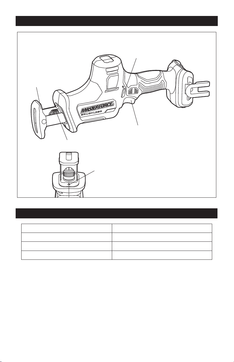
OVERVIEW
SPECIFICATIONS
Rated Voltage 20 V d.c.
No-load Speed 0-3,100 SPM
Blade Stroke 1 in. (25 mm)
Weight (without battery) 3 lb 14 oz
Pivot Shoe
Lock-Off Button
Tool-Less Blade Clamp
Variable-Speed Trigger Switch
LED Worklight
Page 8
ASSEMBLY
WARNING:
If any part is broken or
missing, DO NOT attach the battery pack
or operate the tool until the broken or
missing part is replaced. Failure to do so
could result in possible serious injury.
WARNING:
Do not attempt to
modify this tool or create accessories not
recommended for use with this tool. Any
such alteration or modication is misuse
and could result in a hazardous condition
leading to possible serious injury.
WARNING:
Your tool should
never be connected to the battery pack
when you are assembling parts, making
adjustments, cleaning, or when it is not in
use. Disconnecting the tool will prevent
accidental starting, which could cause
serious personal injury.
CONTENTS
Compact reciprocating saw, blade, belt clip,
screw and instruction manual.
UNPACKING
1. Carefully remove the tool and any
accessories from the carton. Make sure
that all items listed in the packing list are
included.
2. Inspect the tool carefully to make sure
that no breakage or damage occurred
during shipping.
3. Do not discard the packing material
until you have carefully inspected and
satisfactorily operated the tool.
OPERATION
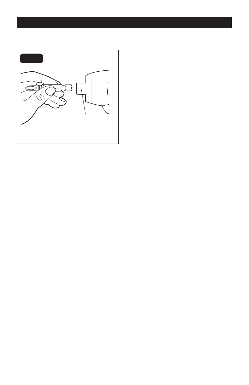
TO ATTACH BATTERY PACK
(FIG.1)
FIG. 1
Battery-Release Button
1. Align the raised rib on the battery pack
with the grooves on the bottom of the
tool, then slide the battery pack onto the
tool.
2. Ensure that the battery-release button
on the battery pack snap into place and
the battery pack is secured to the tool
before beginning operation.
NOTICE: When placing the battery pack
on the tool, be sure that the raised rib on
the battery pack aligns with the groove on
the tool and the latches snap into place
properly. Improper assembly of the battery
pack can cause damage to internal
components.
TO DETACH BATTERY
PACK (FIG.1)
1. Press the battery-release button to
release the battery pack.
2. Pull the battery pack to remove it from
the tool.
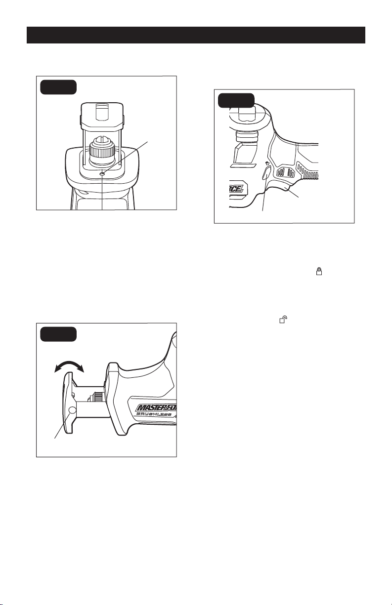
Page 9
OPERATION
LED WORKLIGHT (FIG.2)
FIG. 2
LED
Worklight
The LED worklight, located on the front of the
tool, will illuminate when the trigger switch
is depressed before the tool is running. This
provides additional light on the surface of
the workpiece. The light will automatically
turn off within 10 seconds after releasing the
trigger.
PIVOT SHOE (FIG.3)
FIG. 3
Pivot Shoe
The shoe pivots to provide maximum
contact with the surface being cut.
1. Remove the battery pack from the saw.
2. Hold the saw securely, and then pivot
the shoe to the desired angle.
VARIABLE-SPEED TRIGGER
SWITCH (FIG.4)
FIG. 4
Lock-Off Button
Your reciprocating saw is equipped with a
variable-speed trigger switch to turn the
saw on and off and to control the speed.
1. To start the saw, press the lock-off
button to the direction of “ ” (right side
of the tool) and then squeeze the trigger
switch.
2. To stop the saw, release the trigger
switch and press the lock-off button to
the direction of “
” (left side of the tool)
to lock the trigger switch in the “OFF”
position.
VARIABLE-SPEED (FIG.4)
The variable-speed trigger switch delivers
higher speed with increased trigger pressure
and lower speed with decreased trigger
pressure.
Variable-Speed
Trigger Switch
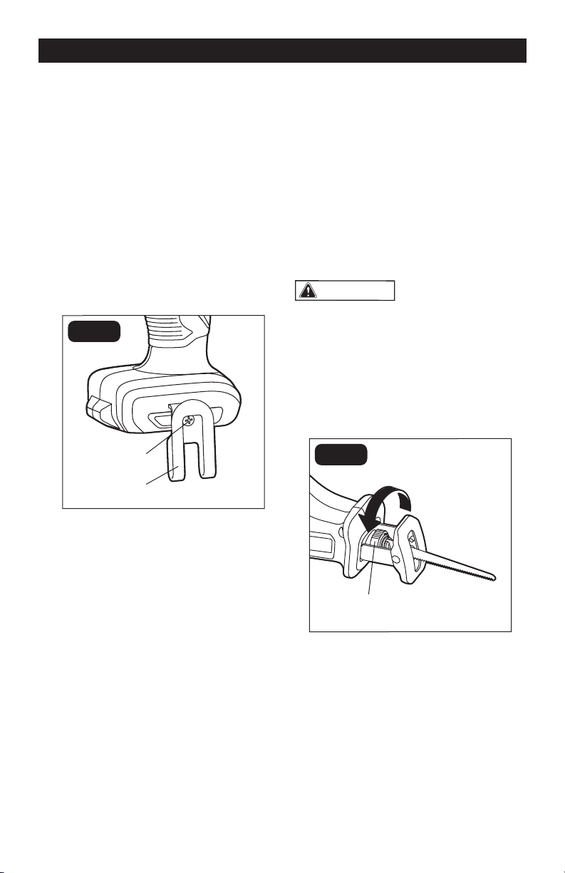
Page 10
OPERATION
INSTALL THE BELT CLIP
(FIG.5)
1. Align the rib of the belt clip with the
hole on the base of the reciprocating
saw.
2. Insert the screw and tighten the
screw securely with a screwdriver.
The belt clip can be positioned on
the left side of the tool.
REMOVE THE BELT CLIP
(FIG.5)
FIG. 5
1. Use a screwdriver to loosen the
screw that attaches the belt clip to
the tool.
2. Remove the screw and the belt clip.
INSTALLING THE BLADE
(FIG.6)
1. Remove the battery pack from the tool.
2. Turn the tool-less blade clamp
counterclockwise.
3. Insert the blade into the slot in the blade
clamp.
4. Release the blade clamp to lock the
blade in place.
NOTICE: The blade may be installed with
the teeth pointing up or down, according
to the requirements of the cutting
operation.
WARNING:
When changing the
blade, always wear protective gloves.
The sharp edges of the blade will cause
personal injury.
REMOVING THE BLADE
(FIG. 6)
FIG. 6
Tool-Less Blade Clamp
NOTICE: When removing a blade following
operation, allow the blade to cool before
removing it to avoid possible burning from
the hot blade.
1. Remove the battery pack from the tool.
2. Turn the tool-less blade clamp
counterclockwise.
3. Pull the blade out of the blade clamp.
Screw
Belt Clip
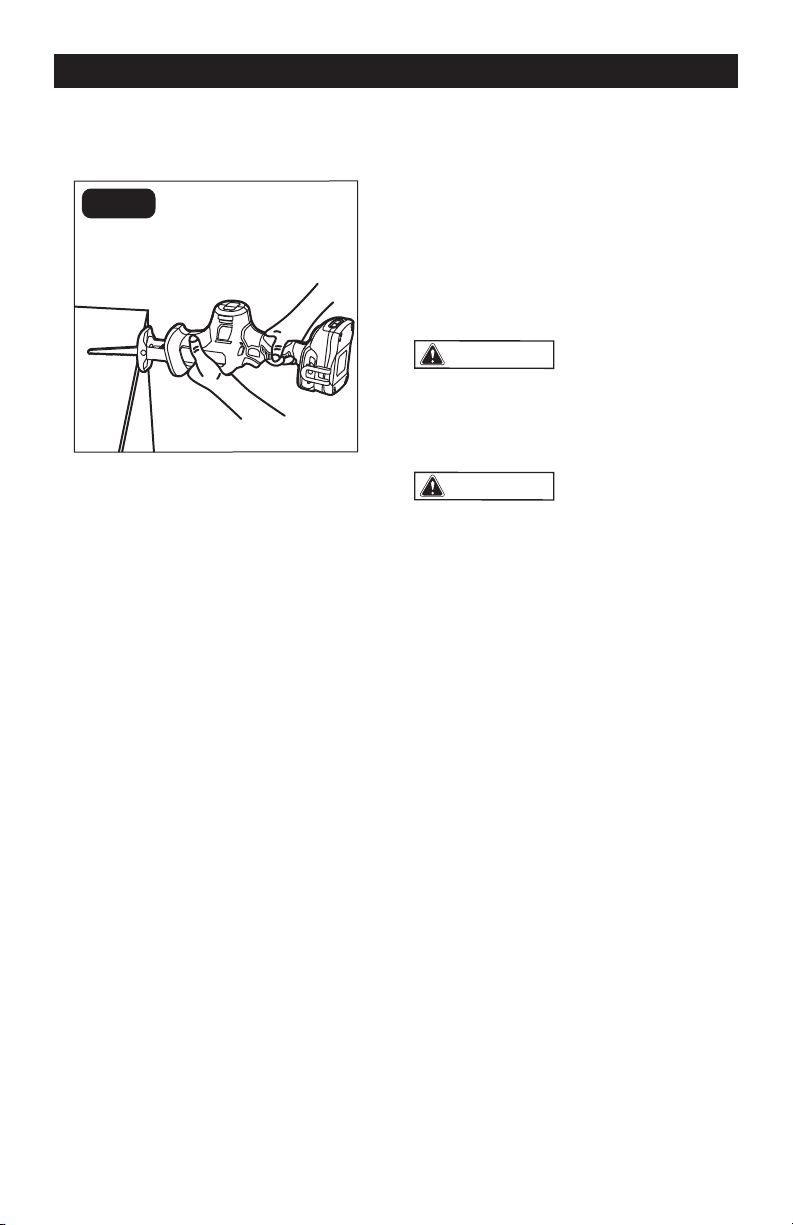
Page 11
OPERATION
GENERAL CUTTING
(FIG.7)
FIG. 7
1. Remove the battery pack from the saw.
2. Make sure that the workpiece is firmly
clamped in place.
3. Install the appropriate type and size of
blade for the workpiece material and
size.
4. Adjust the pivot shoe as necessary
to provide maximum contact with the
surface being cut.
5. Check for clearance behind the
workpiece so that the blade will not
impact another surface.
6. Mark the line of cut clearly. If cutting
metal, apply cutting oil to the cutting
line.
7. Attach the battery pack to the saw.
8. Hold the saw firmly with both hands.
Make sure to keep your hands on the
insulated gripping areas only.
9. Press the lock-off button to the right
side of the tool and then squeeze the
trigger switch to start saw; allow it to
reach the maximum desired cutting
speed before applying the blade to the
workpiece.
10. Place the flat surface of the pivot shoe
firmly on the workpiece while cutting.
Use only enough steady pressure on the
blade to keep the saw cutting; do not
force the tool.
11. Reduce pressure as the blade comes to
the end of the cut.
12. Allow the saw to come to a complete
stop before removing the blade from the
workpiece.
13. If sawing fiberglass, plaster, wallboard,
or spackling compound, clean the
motor vents frequently with a vacuum
or compressed air. These materials are
highly abrasive and may accelerate the
wear on motor bearings and brushes.
NOTICE: Cutting speeds should vary with
the workpiece. Hard materials, such as
metals, require lower speeds; use higher
speeds for softer materials.
WARNING:
Before attaching the
battery pack to the tool, always check
to determine that the switch performs
properly and returns to the “OFF” position
when released.
WARNING:
Hold the tool only by
the plastic handle and the insulated grip
area to help prevent electric shock. You
may encounter electrical wiring when
sawing into walls or oors. Sawing into a
“live” wire will cause electric shock.
METAL CUTTING
The saw can be used to cut metals, such
as sheet steel, pipe, steel rods, aluminum,
brass, and copper. Be careful not to twist or
bend the saw blade. Do not force the tool.
The use of cutting oil is recommended when
cutting soft metals and steel. Cutting oil will
keep the blade cool, increase cutting action,
and prolong blade life.
1. Securely clamp the workpiece in
position and make the cut close to the
clamping point to minimize vibration.
2. When cutting conduit pipe or angle iron,
clamp the work in a vise, if possible, and
cut close to the vise.
3. To cut thin sheet material, “sandwich”
the material between pieces of
hardboard or plywood and clamp the
layers together to reduce vibration and
tearing of the material.

Page 12
TROUBLESHOOTING
WARNING:
Always wear safety
goggles or safety glasses with side
shields during power tool operations, or
when blowing dust. If operation is dusty,
also wear a dust mask.
WARNING:
Do not at any time let
brake uids, gasoline, petroleum - based
products, penetrating oils, etc. come in
contact with plastic parts. Chemicals can
damage, weaken or destroy plastic, which
may result in serious personal injury.
MAINTENANCE
1. Inspect the reciprocating saw, the
trigger switch and the accessories for
damage.
2. Check for damaged, missing, or worn
parts.
3. Check for loose screws, misalignment
or binding of moving parts, or any other
condition that may affect the operation.
4. If abnormal vibration or noise occurs,
turn the tool off immediately and have
the problem corrected before further
use.
5. Detach the battery from the saw before
cleaning or performing any maintenance.
Using compressed air may be the most
effective cleaning method. Always wear
safety goggles when cleaning tools
using compressed air.
PROBLEM POSSIBLE CAUSE SOLUTION
The tool does not work.
The battery is depleted. Charge the battery.
The tool or the battery is
overloaded.
Decrease the load on the
tool and restart the tool.
The tool or the battery is
overheated.
Cool the tool and battery
and start the tool again.
Cutting is difficult. Saw blade is worn out. Replace the saw blade.

Page 13
NOTES

Page 14
SAVE YOUR RECEIPTS
THIS WARRANTY IS VOID WITHOUT THEM
COMPACT RECIPROCATING SAW
WARRANTY
90-DAY MONEY BACK GUARANTEE:
This MASTERFORCE
®
brand power tool carries our 90-DAY Money Back
Guarantee. If you are not completely satisfied with your MASTERFORCE
®
brand
power tool for any reason within ninety (90) days from the date of purchase, return
the tool with your original receipt to any MENARDS
®
retail store, and we will provide
you a refund – no questions asked.
3-YEAR LIMITED WARRANTY:
This MASTERFORCE
®
brand power tool carries our famous No Hassle 3-Year
Limited Warranty to the original purchaser. If, during normal use, this
MASTERFORCE
®
power tool breaks or fails due to a defect in material or
workmanship within three (3) years from the date of original purchase, simply bring
this tool with the original sales receipt back to your nearest MENARDS
®
retail store.
At its discretion, MASTERFORCE
®
agrees to have the tool or any defective part(s)
repaired or replaced with the same or similar MASTERFORCE
®
product or part
free of charge, within the stated warranty period, when returned by the original
purchaser with original sales receipt. Not withstanding the foregoing, this limited
warranty does not cover any damage that has resulted from abuse or misuse of the
Merchandise. This warranty: (1) excludes expendable parts including but not limited
to blades, brushes, belts, bits, light bulbs, and/or batteries; (2) shall be void if this
tool is used for commercial and/or rental purposes; and (3) does not cover any
losses, injuries to persons/property or costs. This warranty does give you specific
legal rights and you may have other rights, which vary from state to state. Be
careful, tools are dangerous if improperly used or maintained. Seller’s employees
are not qualified to advise you on the use of this Merchandise. Any oral
representation(s) made will not be binding on seller or its employees. The rights
under this limited warranty are to the original purchaser of the Merchandise and may
not be transferred to any subsequent owner. This limited warranty is in lieu of all
warranties, expressed or implied including warranties or merchantability and fitness
for a particular purpose. Seller shall not be liable for any special, incidental, or
consequential damages. The sole exclusive remedy against the seller will be for the
replacement of any defects as provided herein, as long as the seller is willing or
able to replace this product or is willing to refund the purchase price as provided
above. For insurance purposes, seller is not allowed to demonstrate any of these
power tools for you.
For questions / comments, technical assistance or repair parts – Please Call Toll
Free: 1-866-917-4374 (M-F 8:30am-5:00pm EST).

05/2020
© 2020 Menard, Inc., Eau Claire, WI 54703
241-0444
LED Spot Light
OPERATOR’S MANUAL
CAUTION:
To Reduce The Risk Of Injury, User Must
Read And Understand Operator’s Manual. Save These
Instructions For Future Reference.
For questions / comments, technical assistance or repair parts –
Please Call Toll Free: 1-866-917-4374. (M-F 8:30am-5:00pm Est.)

TABLE OF CONTENTS
Safety Symbols ..........................................................Page 2
Safety Instructions .......................................................Page 3
Overview/Specifications ..................................................Page 6
Assembly ..............................................................Page 7
Operation ..............................................................Page 8
Maintenance ...........................................................Page 10
Troubleshooting ........................................................Page 11
Warranty ..............................................................Page 14
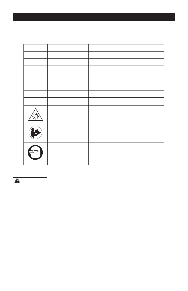
Page 2
SAFETY SYMBOLS
Some of these following symbols may be used on this tool. Please study them and learn their
meaning. Proper interpretation of these symbols will allow you to operate the tool better and
more safely.
Symbol
Name
Designation / Explanation
V Volts Voltage
A Amperes Current
Hz Hertz Frequency (cycles per second)
W Watts Power
lbs Pounds Weight
n
o
No-load speed Rotational speed at no load
� or d.c.
Direct current Type of characteristic of current
Do not stare at
operating lamp
To reduce the risk of injury, do not stare
at operating lamp. Serious eye injury
could occur.
Read instruction
manual
To reduce the risk of injury, user must
read instruction manual.
Wear safety goggles
To reduce the risk of injury, always wear
eye protection.
WARNING:
To ensure safety and reliability, all repairs should be performed by a
qualified service technician.
Page 3
SAFETY INSTRUCTIONS
The purpose of safety symbols is to attract your attention to possible dangers. The safety
symbols, and the explanations with them, deserve your careful attention and understanding.
The symbol warnings do not, by themselves, eliminate any danger. The instructions and
warnings they give are no substitutes for proper accident prevention measures.
WARNING:
Be sure to read and understand all safety instructions in this manual,
including all safety alert symbols such as “DANGER”, “WARNING” and “CAUTION” before
using this tool. Failure to follow all instructions listed below may result in electric shock,
fire, and/or serious personal injury.
SYMBOL MEANING
SAFETY ALERT SYMBOL: Indicates DANGER, WARNING, OR CAUTION. May be
used in conjunction with other symbols or pictographs.
DANGER:
Indicates an imminently hazardous situation, which, if not avoided, will
result in death or serious injury.
WARNING:
Indicates a potentially hazardous situation, which, if not avoided,
could result in death or serious injury.
CAUTION:
Indicates a potentially hazardous situation, which, if not avoided, could
result in minor or moderate injury.
NOTICE: (Without Safety Alert Symbol) Indicates a situation that may result in property
damage.
SAVE THESE INSTRUCTIONS!

Page 4
SAFETY INSTRUCTIONS
SPECIFIC SAFETY WARNINGS
FOR LED WORK LIGHT
WARNING:
Read all safety
warnings, instructions, illustrations and
specifications provided with this power
tool. Failure to follow all instructions listed
below may result in electric shock, fire and/
or serious injury.
• Prevent unintentional starting. Ensure
the switch is in the off-position before
connecting to battery pack, picking up
or carrying the appliance. Carrying the
appliance with your finger on the switch or
energizing appliance that have the switch
on invites accidents.
• Disconnect the battery pack from the
appliance before making any adjustments,
changing accessories, or storing
appliance. Such preventive safety measures
reduce the risk of starting the appliance
accidentally.
• Do not direct the light beam at persons
or pets and avoid staring into the light even
from a distance.
• Recharge battery packs only with the
charger specified by the manufacturer.
A charger that is suitable for one type of
battery pack may create a risk of fire when
used with another battery pack.
• Use appliances only with specifically
designated battery packs. Use of any other
battery packs may create a risk of injury and
fire.
• When battery pack is not in use, keep
it away from other metal objects, like
paper clips, coins, keys, nails, screws or
other small metal objects, that can make
a connection from one terminal to another.
Shorting the battery terminals together may
cause burns or a fire.
• Under abusive conditions, liquid may
be ejected from the battery; avoid contact.
If contact accidentally occurs, flush with
water. If liquid contacts eyes, additionally
seek medical help. Liquid ejected from the
battery may cause irritation or burns.
• Do not use a battery pack or appliance
that is damaged or modified. Damaged or
modified batteries may exhibit unpredictable
behavior resulting in fire, explosion or risk of
injury.
• Do not expose a battery pack or
appliance to fire or excessive temperature.
Exposure to fire or temperature above 265°F
(130°C) may cause explosion.
• Follow all charging instructions and do
not charge the battery pack or appliance
outside of the temperature range specified
in the instructions. Charging improperly
or at temperatures outside of the specified
range may damage the battery and increase
the risk of fire.
• Have servicing performed by a
qualified repair person using only identical
replacement parts. This will ensure that the
safety of the product is maintained.
• Do not modify or attempt to repair the
appliance or the battery pack except as
indicated in the instructions for use and
care.
• To reduce the risk of injury, close
supervision is necessary when a product is
used near children.
• Do not contact hot parts.
• Only use attachments recommended
or sold by the manufacturer.
• Do not use in the rain.
• To reduce the risk of electrical shock,
do not put the appliance in water or other
liquid. Do not place or store product where
it can fall or be pulled into a tub or sink.
• To reduce the risk of injury, do not stare
at operating lamp. Serious eye injury could
occur.
CAUTION:
• Hot surface.
• Risk of burns - Do not touch.
• Risk of fire - Keep away from combustible
materials.
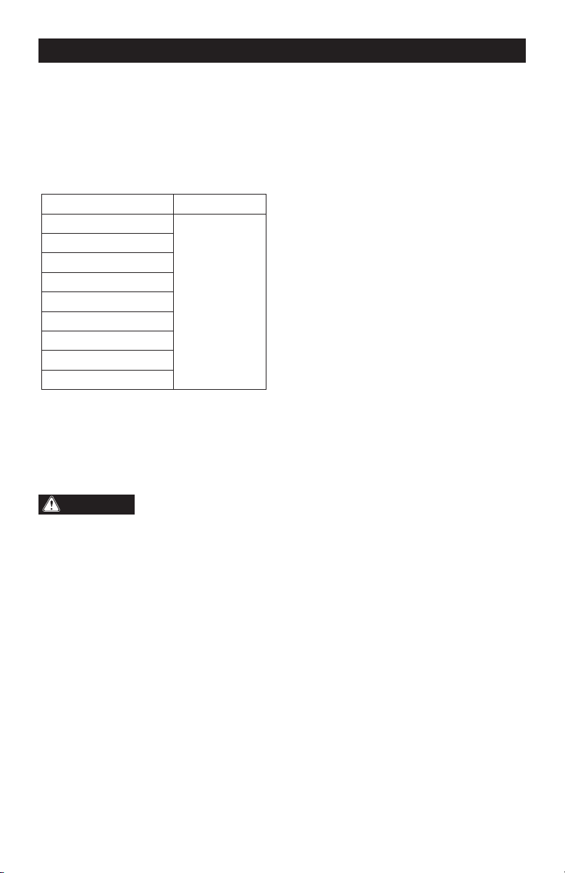
Page 5
IMPORTANT SAFETY
INSTRUCTIONS
1. To reduce the risk of electric shock
or damage to the chargers and batteries,
use only with the MASTERFORCE
®
battery
packs and chargers listed.
Battery pack Charger
252-8029 (1.5Ah)
252-8025
252-8037
252-8026
252-8031 (2.0Ah)
252-8030 (2.5Ah)
252-8003 (2.5Ah)
252-8034 (4.0Ah)
252-8035 (5.0Ah)
252-8005 (5.0Ah)
252-8027 (7.5Ah)
252-8007 (7.5Ah)
2. For best results, your battery and tool
should be stored, charged and used in a
location where the temperature is more
than 5°C (41°F) but less than 40°C (104°F).
Do not store outside or in vehicles.
DANGER:
People with electronic
devices, such as pacemakers, should
consult their physician(s) before using this
product. Operation of electrical equipment
in close proximity to a heart pacemaker
could cause interference or failure of the
pacemaker.
SAVE THESE INSTRUCTIONS!
SAFETY INSTRUCTIONS
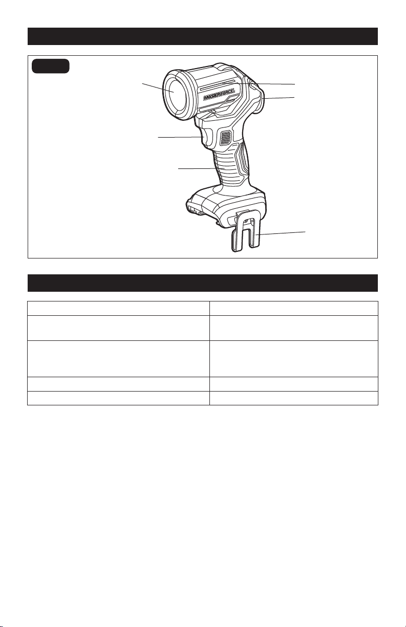
Page 6
Lens (Transparent Cover)
Hanging Loop
Pivoting Head
Belt Clip
ON/OFF Switch
FIG. 1
SPECIFICATIONS
Rated Voltage 20 V d.c.
Luminous Flux (brightness) 150 Lumens -Low
330 Lumens - High
BOOST 2.5 Ah Runtime
BOOST 5.0 Ah Runtime
BOOST 7.5 Ah Runtime
27 h (low), 10.5 h (high)
54 h (low), 21.5 h (high)
80 h (low), 32 h (high)
Head Pivot Range 0–104°
Weight (without battery) 13 oz. (0.37kg)
OVERVIEW
Handle

Page 7
ASSEMBLY
WARNING:
If any part is broken or
missing, DO NOT attach the battery pack
or operate the light until the broken or
missing part is replaced. Failure to do so
could result in possible serious injury.
WARNING:
Do not attempt to
modify this light or create accessories not
recommended for use with this light. Any
such alteration or modification is misuse
and could result in a hazardous condition
leading to possible serious injury.
WARNING:
Your light should
never be connected to the battery pack
when you are assembling parts, making
adjustments, cleaning, or when it is not
in use.
CONTENTS
Cordless Work Light
Belt Clip
Screw for Belt Clip
Instruction Manual
UNPACKING
1. Carefully remove the light and any
accessories from the carton. Make sure
that all items listed in the packing list are
included.
2. Inspect the light carefully to make sure
that no breakage or damage occurred
during shipping.
3. Do not discard the packing material
until you have carefully inspected and
satisfactorily operated the light.
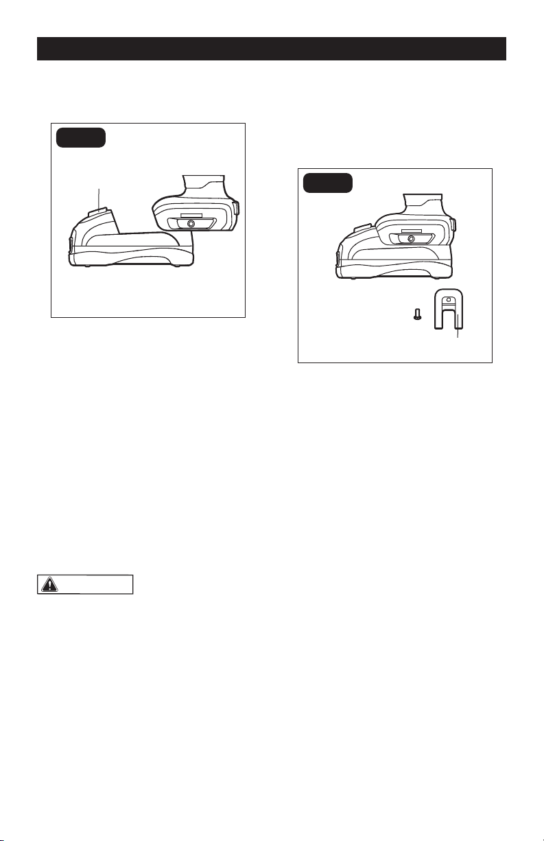
Page 8
OPERATION
TO ATTACH BATTERY PACK
(FIG. 1)
FIG. 1
1. Align the raised rib on the battery pack
with the grooves on the bottom of the
light, then slide the battery pack onto
the light.
2. Ensure that the battery-release button
on the battery pack snaps into place
and the battery pack is secured to the
light before beginning the operation.
NOTICE: When placing the battery pack
on the light, be sure that the raised rib on
the battery pack aligns with the groove
on the light and the latches snap into
place properly. Improper assembly of the
battery pack can cause damage to internal
components.
WARNING:
Do not direct the
light beam at persons or animals before
attaching the battery pack. The light will
be on if you didn’t turn off the light last
time. Turn the light off before detaching
the battery pack.
TO DETACH BATTERY PACK
(FIG. 1)
1. Press the battery-release button to
release the battery pack.
2. Pull the battery pack to remove it from
the light.
TO INSTALL THE BELT CLIP
(FIG. 2)
Belt Clip
FIG. 2
1. Remove the battery pack from the light.
2. Align the rib of the belt clip with the hole
on the base of the light.
3. Insert the screw and securely tighten the
screw with a screwdriver (not included).
TO REMOVE THE BELT CLIP
(FIG. 2)
1. Remove the battery pack from the light.
2. Use a screwdriver (not included) to
loosen the screw that attaches the belt
clip to the light.
3. Remove the screw and the belt clip.
Keep them in a safe place for future use.
Battery-Release Button
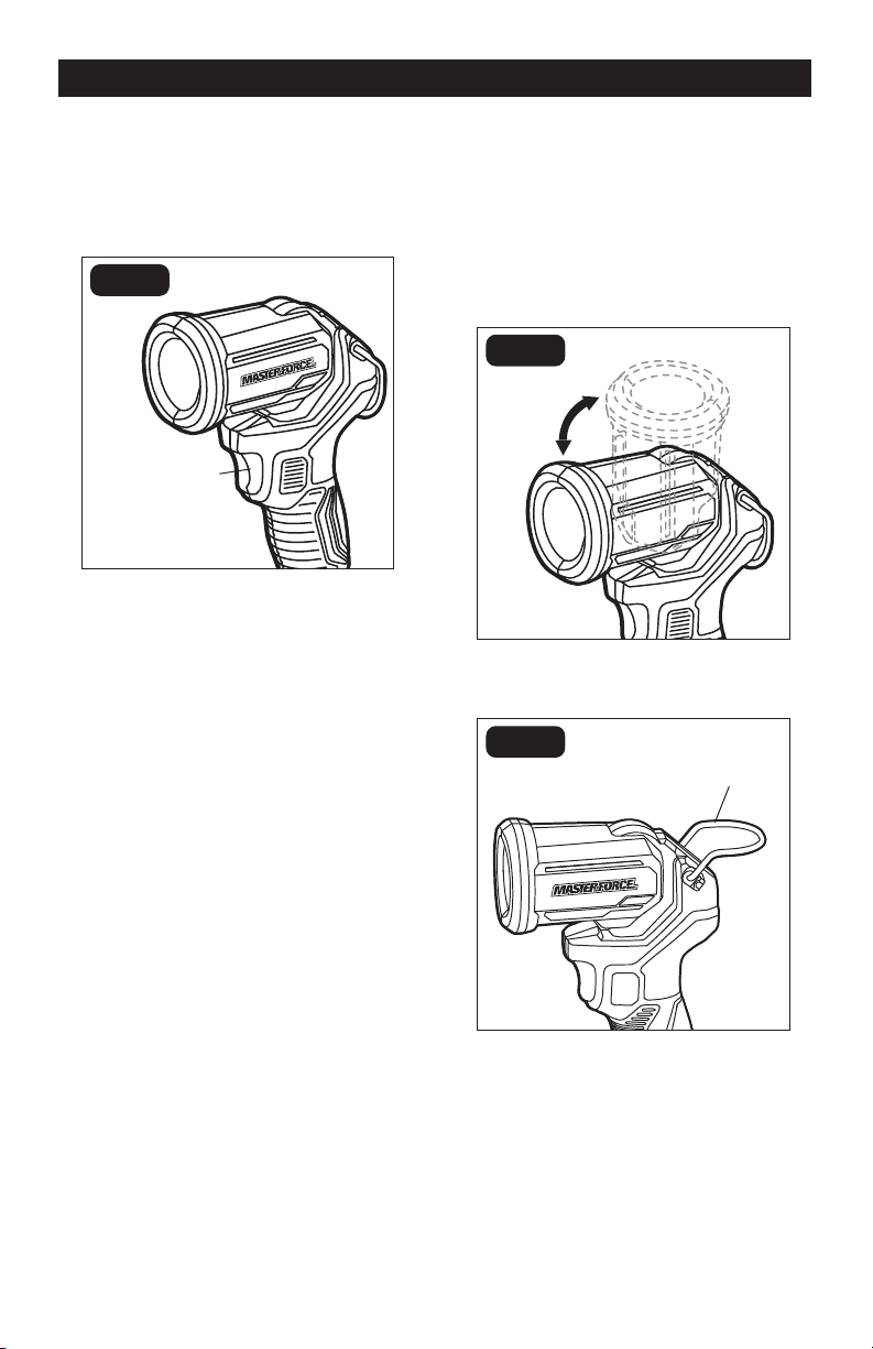
Page 9
OPERATION
TWO-STAGE BRIGHTNESS AD-
JUSTMENT CONTROLLED BY
ON/OFF SWITCH
(FIG. 3)
FIG. 3
Your tool is equipped with a two-stage
brightness adjustment, providing different
light intensities for your operation. Depress
the on/off switch to turn on the light: the
light is in the high light mode. Depress the
on/off switch again to changeto the low
light mode. Depress a third time to turn the
light off.
PIVOTING HEAD
(FIG. 4)
The light head pivots 104° for maximum
flexibility. Manually move the head to any
position within the pivot range. Do not force
the head beyond that range.
HANGING LOOP (FIG. 5)
FIG. 5
Your tool is equipped with a loop. It can be
carried or hung on a hook or a hook-like
object.
To prevent the risk of injury or product
damage make sure that the hook is sturdy
enough to hold the weight of the light with
attached battery pack.
ON/OFF Switch
Hanging Loop
MAX: 104
o
FIG. 4

Page 10
MAINTENANCE
WARNING:
To avoid serious personal injury, always
remove the battery pack from the
light when cleaning or performing any
maintenance.
When servicing, use only identical
replacement parts. The use of any other
parts may create a hazard or cause
damage to the product.
All maintenance should only be carried
out by a qualified repair person.
CLEANING
Always use only a soft, dry cloth to clean
the plastic transparent cover, never use
detergent or alcohol.
Always wear safety goggles when
cleaning with compressed air.
Do not at any time let brake fluids,
gasoline, petroleum-based products,
penetrating oils, etc. come in contact with
plastic parts. Chemicals can damage,
weaken or destroy plastic, which may
result in serious personal injury.

Page 11
TROUBLESHOOTING
PROBLEM POSSIBLE CAUSE SOLUTION
The light does
not work.
The battery pack is depleted. Charge the battery pack.
The battery pack is not
installed properly.
Confirm that battery pack is properly
secured to the light.
The light or the battery pack is
overheated.
Allow the light and battery pack to
cool down before restarting the light.

Page 12
NOTES

Page 13
NOTES

SAVE YOUR RECEIPTS
THIS WARRANTY IS VOID WITHOUT THEM
LED Spot Light
WARRANTY
90-DAY MONEY BACK GUARANTEE:
This MASTERFORCE® brand power tool carries our 90-DAY Money Back
Guarantee. If you are not completely satisfied with your MASTERFORCE® brand
power tool for any reason within ninety (90) days from the date of purchase, return
the tool with your original receipt to any MENARDS® retail store, and we will provide
you a refund – no questions asked.
3-YEAR LIMITED WARRANTY:
This MASTERFORCE® brand power tool carries our famous No Hassle 3-Year
Limited Warranty to the original purchaser. If, during normal use, this
MASTERFORCE® power tool breaks or fails due to a defect in material or
workmanship within three (3) years from the date of original purchase, simply bring
this tool with the original sales receipt back to your nearest MENARDS® retail store.
At its discretion, MASTERFORCE® agrees to have the tool or any defective part(s)
repaired or replaced with the same or similar MASTERFORCE® product or part
free of charge, within the stated warranty period, when returned by the original
purchaser with original sales receipt. Not withstanding the foregoing, this limited
warranty does not cover any damage that has resulted from abuse or misuse of the
Merchandise. This warranty: (1) excludes expendable parts including but not limited
to blades, brushes, belts, bits, light bulbs, and/or batteries; (2) shall be void if this
tool is used for commercial and/or rental purposes; and (3) does not cover any
losses, injuries to persons/property or costs. This warranty does give you specific
legal rights and you may have other rights, which vary from state to state. Be
careful, tools are dangerous if improperly used or maintained. Seller’s employees
are not qualified to advise you on the use of this Merchandise. Any oral
representation(s) made will not be binding on seller or its employees. The rights
under this limited warranty are to the original purchaser of the Merchandise and may
not be transferred to any subsequent owner. This limited warranty is in lieu of all
warranties, expressed or implied including warranties or merchantability and fitness
for a particular purpose. Seller shall not be liable for any special, incidental, or
consequential damages. The sole exclusive remedy against the seller will be for the
replacement of any defects as provided herein, as long as the seller is willing or
able to replace this product or is willing to refund the purchase price as provided
above. For insurance purposes, seller is not allowed to demonstrate any of these
power tools for you.
For questions / comments, technical assistance or repair parts – Please Call Toll
Free at: 1-866-917-4374. (M-F 8:30am-5:00pm Est.)
Page 14

Page 15
04/2021
© 2021 Menard, Inc., Eau Claire, WI 54703