
HTM200
Series
Multi-channel Temperature Recorder
User Manual
2022.06

Warranties and Representations
Copyright
This document is copyrighted by Qingdao Hantek Electronics Co., LTD.
Statement
Qingdao Hantek Electronics Co., Ltd. reserves the right to amend this document without prior notice.
Qingdao Hantek Electronics Co., Ltd. promises that the information provided is correct and reliable
but does not guarantee that this document is without error. Please make sure that the specifications
of relevant technical documents used are the latest and valid version before using the product. If a
company uses documents or products of Qingdao Hantek Electronics Co., LTD. and requires
products, patents, or works of a third party, the company shall be responsible for obtaining the
consent and authorization of the third party. The above consent and authorization shall not be the
liability of Hantek.
Product Certification
The product complies with China national product standards and industry product standards, as well
as ISO9001:2015 and ISO14001:2015 standards, and will further complete the certifications of other
members of international standard organizations.
Contact Us
If you encounter any problems in the process of using the products of Qingdao Hantek
Electronics
Co., LTD., you can obtain services and support through the following ways:
Email: service@hantek.com, support@hantek.com
Website: http://www.hantek.com

EN
Copyright Qingdao Hantek Electronics Co., LTD HTM200 user manual
I
Contents
Contents............................................................................................................................................I
Figures............................................................................................................................................. V
Tables..........................................................................................................................................VIIII
1 Safety Requirements .................................................................................................................1
1.1 Summary of general security issues ................................................................................ 1
1.2 Safety Notices and Symbols ............................................................................................ 2
1.3 Measurement Category ....................................................................................................3
1.4 Working Environment ....................................................................................................... 3
1.5 Maintenance and Cleaning ...............................................................................................5
1.6 Environmental Considerations ......................................................................................... 5
2 Product features ......................................................................................................................... 7
3 Document Overview .................................................................................................................. 8
4 Quick Start .................................................................................................................................10
4.1 General Inspection..........................................................................................................................10
4.2 Appearance and Dimensions.......................................................................................................11
4.3 Preparation before Use................................................................................................................. 11
4.3.1 Adjusting the Stand ............................................................................................................... 11

EN
HTM200 user manual Copyright Qingdao Hantek Electronics Co., LTD
II
4.3.2 Charging ................................................................................................................................12
4.3.3 Turn-on check ....................................................................................................................... 13
4.3.4 Set the system language .......................................................................................................13
4.3.5 Test terminal connection .......................................................................................................13
4.3.6 Product Introduction .............................................................................................................. 14
4.3.7 Front Panel Overview ............................................................................................................14
4.3.8 Side Panel Overview .............................................................................................................16
4.3.9 Top Panel Overview ..............................................................................................................17
4.3.10 User Interface ......................................................................................................................17
4.4 Storage and replacement of batteries........................................................................................19
4.4.1 Battery storage
....................................................................................................................................... 19
4.4.2 Battery replacement .............................................................................................................................. 20
4.5 Safety lock hole............................................................................................................................... 22
5 Function introduction ...............................................................................................................23
5.1 Measurement list.............................................................................................................................23
5.2 Measurement bar chart................................................................................................................. 23
5.3 Channel configuration....................................................................................................................24
5.4 System settings............................................................................................................................... 25
5.4.1 User
...........................................................................................................................................................25

EN
Copyright Qingdao Hantek Electronics Co., LTD HTM200 user manual
III
5.4.2 File
.............................................................................................................................................................26
5.4.3 Service
......................................................................................................................................................28
5.5 Firmware update............................................................................................................................. 28
5.6 Error code description ....................................................................................................................29
6 Remote control and data transmission ................................................................... 30
6.1 Control via USB ...............................................................................................................................30
6.2 Control via Bluetooth ......................................................................................................................31
6.3 Network data transmission ........................................................................................................... 31
7 Android application ..................................................................................................................33
7.1 Application download and installation........................................................................................33
7.2 Application introduction................................................................................................................. 34
7.2.1 Main interface ......................................................................................................................................... 34
7.2.2 Setting Interface
..................................................................................................................................... 35
8 Windows Software ...................................................................................................................39
8.1 Software Download and Installation...........................................................................................39
8.2 Software Functions.........................................................................................................................40
8.2.1 User Interface
......................................................................................................................................... 40
8.2.2 File Storage ............................................................................................................................................. 40
8.2.3 Connection Method
............................................................................................................................... 41

EN
HTM200 user manual Copyright Qingdao Hantek Electronics Co., LTD
IV
8.2.4 Record
...................................................................................................................................................... 44
8.2.5 Display
......................................................................................................................................................44
8.2.6 Shortcuts ..................................................................................................................................................45
8.2.7 Channel settings .................................................................................................................................. 46
9 Troubleshooting........................................................................................................................47
10 Appendix..................................................................................................................................48
10.1 Appendix A: Accessories............................................................................................................48

EN
Copyright Qingdao Hantek Electronics Co., LTD HTM200 user manual
V
Figures
Figure 4.1 Front view and side view ................................................................................11
Figure 4.2 Adjusting the stand.......................................................................................... 12
Figure 4.3 Test interface .....................................................................................................13
Figure 4.4 Front panel .........................................................................................................14
Figure 4.5 Side panel ..........................................................................................................16
Figure 4.6 Top panel ............................................................................................................17
Figure 4.7 User interface ....................................................................................................17
Figure 4.8 Open the stand ................................................................................................. 20
Figure 4.9 Install the battery ..............................................................................................21
Figure 4.10 Safety lock hole ..............................................................................................22
Figure 5.1 Measurement list ..............................................................................................23
Figure 5.2 Measurement bar chart ...................................................................................24
Figure 5.3 Data preservation instance ............................................................................28
Figure 6.1 USB connection diagram ............................................................................... 31
Figure 7.1 Application download QR code .....................................................................33
Figure 7.2 Main interface of the Android application ................................................... 34
Figure 7.3 Channel settings ...............................................................................................35
Figure 7.4 Android application setting interface ............................................................35
Figure 7.5 Data source selection ......................................................................................36
Figure 7.6 Import network data .........................................................................................36

EN
HTM200 user manual Copyright Qingdao Hantek Electronics Co., LTD
VI
Figure 7.7 Data file export ..................................................................................................37
Figure 7.8 Data file import ..................................................................................................37
Figure 7.9 Delete file ........................................................................................................... 37
Figure 7.10 Channel settings............................................................................................ 38
Figure 7.11 Line chart settings ..........................................................................................38
Figure 8.1 Windows software user interface ................................................................. 40
Figure 8.2 File menu ............................................................................................................40
Figure 8.3 Connection menu .............................................................................................41
Figure 8.4 Communication connection window ............................................................42
Figure 8.5 Windows software data collection................................................................42
Figure 8.6 Bluetooth connection.......................................................................................43
Figure 8.7 Viewing historical data .................................................................................... 43
Figure 8.8 Record menu .....................................................................................................44
Figure 8.9 Display menu .....................................................................................................44
Figure 8.10 Track................................................................................................................. 44
Figure 8.11 Zoom ................................................................................................................. 45
Figure 8.12 Shortcuts..........................................................................................................45
Figure 8.13 Channel settings............................................................................................ 46

EN
Copyright Qingdao Hantek Electronics Co., LTD HTM200 user manual
VII
Tables
Table 3.1 Model list .................................................................................................................9
Table 4.1 Status display......................................................................................................19
Table 5.1 Channel configuration descriptions............................................................... 25
Table 5.2 Function menu descriptions............................................................................ 25
Table 5.3 User menu table .................................................................................................26
Table 5.4 File menu table................................................................................................... 27
Table 5.5 Function menu descriptions............................................................................ 27
Table 5.6 Error code descriptions .....................................................................................29
Table 6.1 Network connection status symbols ..............................................................32

Safety Requirements
EN
Copyright Qingdao Hantek Electronics Co., LTD HTM200 user manual
1
1 Safety Requirements
1.1 Summary of general security issues
Carefully read the following safety precautions to avoid injury and to prevent damage to
this product or products connected to it. To avoid potential hazards, please follow the
instructions specified in this manual to use the instrument properly.
Only professionally authorized personnel can perform repairs.
Use Proper power Cord.
Use only the power cable approved by your country.
Ground the product.
To avoid electric shock, the product is grounded through the grounding conductor
of the power cable. The grounding conductor must be connected to the ground
before connecting the input or output end of the product. Ensure that the product is
properly grounded.
Check all terminal ratings.
To avoid fire or excessive current, check all rated values and marking instructions
on the product. Please consult the product manual for details before connecting
the product.
Do not open the cover.
Do not run the product when the outer cover or panel is open.
Avoid circuit exposure.
Do not touch exposed wire terminals and electronic components after the power
supply is switched on.
Do not perform operations when you suspect that the product is faulty.
If you suspect that the product has been damaged, have it inspected by a qualified
maintenance person.
Maintain proper ventilation.
Do not operate in a damp environment.
Do not operate in inflammable and explosive environment.
Please keep the product surface clean and dry.
Safety Requirements
EN
HTM200 user manual Copyright Qingdao Hantek Electronics Co., LTD
2
Anti-static protection
Static electricity may damage the instrument. Therefore, test the instrument in an
anti-static zone. Before connecting the cable to the instrument, ground the inner
and outer conductors briefly to release static electricity.
Use batteries properly. Use the Battery Properly.
If batteries are provided, do not expose them to high temperature or fire. Keep
batteries away from children. Improperly replacing batteries can cause explosions
(warning: lithium-ion batteries). Only the battery specified for the product shall be
used.
Warning:
Equipment that meets class A requirements may not provide adequate protection
against broadcast services in the residential environment.
1.2 Safety Notices and Symbols
Safety notices in the manual:
Warning:
Indicates that this operation may not cause immediate damage to you.
Note:
Indicates that you may damage the product or other property if you do so.
Safety terms on the product:
Warning:
Indicates that if you do not perform this operation, potential harm may be caused.
Safety symbols on the product:
Warning

Safety Requirements
EN
Copyright Qingdao Hantek Electronics Co., LTD HTM200 user manual
3
1.3 Measurement Category
Measurement Category
The instrument can operate under measurement category Ⅰ.
Warning:
This instrument can only be used for measurements within its specified
measurement categories.
Definitions of measurement categories
Measurement Class I refers to measurements made on circuits not directly
connected to the main power supply. For example, circuits that are not derived
from the main power supply, especially from the protected (internal) main power
supply. In the latter case, instantaneous stress changes. Therefore, the user
should be aware of the instantaneous capacity of the device.
Measurement Class II refers to measurements made on circuits directly
connected to low voltage equipment. For example, household appliances, portable
tools and similar equipment.
Measurement Class III refers to measurement in construction equipment. For
example, switchboards, circuit breakers, circuits (including cables, busbars,
junction boxes, switches, sockets) in fixed equipment, equipment for industrial use,
and other equipment (for example, fixed motors permanently connected to fixed
equipment).
Measurement class IV refers to measurement at the source of low-voltage
equipment. For example, electricity meters, measurements on primary overcurrent
protection equipment, and measurements on pulse control units.
1.4 Working Environment
Temperature
Operating: 0℃ - 50 ℃
Non-operating: -20℃ - 60 ℃
Humidity
≤+104℉(≤+40°C): ≤90%RH
106℉~122℉ (+41°C ~50°C): ≤60%RH

Safety Requirements
EN
HTM200 user manual Copyright Qingdao Hantek Electronics Co., LTD
4
Warning:
To avoid short circuit or electric shock, do not operate the device in a damp
environment.
Altitude
Operating and Non-operating: 3,000m (10,000 feet).
Random vibration: 0.31g RMS from 50Hz to 500Hz, 10 minutes in each axial direction.
When not operating: 2.46g RMS from 5Hz to 500Hz, 10 minutes in each axial direction.
ESD Category
ESD + 8 kv
Installation (overvoltage) Category
This product is powered by a main power supply conforming to Installation (overvoltage)
category II.
Warning:
Ensure that no overvoltage (e.g., lightning) reaches the product. Otherwise, the
operator may be in danger of suffering from electric shock.
Definitions of Installation (overvoltage) category
Installation (overvoltage) category I refers to the signal level, which is applicable to the
device measurement terminals connected to the source circuit. Measures have been
taken to limit the instantaneous voltage to the corresponding low level.
Installation (overvoltage) Class II refers to the local distribution, which is applicable to
equipment connected to the AC line (AC power).
Degree of pollution
Class 2
Definition of pollution level
Pollution level 1: No pollution, or only dry non-conductive pollution. This pollution
level has no impact. For example, clean room or air-conditioned office
environment.
Pollution level 2: Generally, only dry non-conductive pollution occurs. Transient

Safety Requirements
EN
Copyright Qingdao Hantek Electronics Co., LTD HTM200 user manual
5
conduction due to condensation may sometimes occur. For example, general
indoor environment.
Pollution level 3: Conductive pollution occurs, or dry non-conductive pollution
becomes conductive due to condensation. For example, an outdoor environment
with a canopy.
Pollution level 4: Permanent conductive pollution through conductive dust, rain,
or snow. For example, outdoor places.
Security level
Level 1 - Grounded products
1.5 Maintenance and Cleaning
Maintenance
Do not expose the LCD to direct sunlight for a long time when storing or placing the
instrument.
Cleaning
Check the instrument frequently as required by the operating conditions. Clean the
outer surface of the instrument according to the following steps:
1)Use lint-free cloth to remove floating dust outside the instrument. Please be careful to
avoid scratching the smooth display.
2) Clean the instrument with a soft cloth soaked in water. For a more thorough cleaning,
use an aqueous solution of 75% isopropyl alcohol.
Note:
To avoid damaging the surface of the instrument, do not use any corrosive
reagent or chemical cleaning reagent.
Warning:
Before powering on again, ensure that the device is dry enough to avoid
electrical short circuit or personal injury caused by moisture.
1.6 Environmental Considerations
The following symbol indicates that the product complies with WEEE Directive

Safety Requirements
EN
HTM200 user manual Copyright Qingdao Hantek Electronics Co., LTD
6
2002/96/EC.
Equipment recycling
Producing this product requires the extraction and use of natural resources. Some
substances contained in the equipment may be harmful to the environment or human
health if the product is not disposed of properly. To avoid the release of harmful
substances and reduce the cost of natural resources, it is recommended that
appropriate methods be used to recycle this product to ensure most of the materials
can be properly reused.

Product features
EN
Copyright Qingdao Hantek Electronics Co., LTD HTM200 user manual
7
2 Product features
Product features
18650 standard lithium battery, support Type-c charging;
Digital signal and analog signal adopt isolation design, can carry on electric test,
safe and reliable;
320*240 TFT HD display, intuitively display multi-channel real-time signal changes,
can switch the temperature list and bar chart in real time;
Support 11 types of thermocouple test, including J/K/T/E/S/N/B/R/A/C/D;
Save the settings of the last shutdown by default, which is convenient for
engineers to measure and record;
Standard with USB disk storage function, support optional Micro SD card data
storage;
Temperature alarm control: when the set temperature is higher than the upper limit
or lower than the lower limit, the buzzer will alarm;
Standard with type-C communication function, support optional Bluetooth module
/4G communication module;
Equipped with Windows and Android data acquisition terminals, support
multi-platform data collection and monitoring;
Widely used in cold storage, warehouse temperature, electronic components
surface measurement and other fields.
HTM200 series handheld multi-channel temperature recorder adopts high-performance
32-bit ARM microprocessor control, can simultaneously collect multi-channel
temperature data in real time, support list display and bar chart display, upper and lower
limit alarm, 11 kinds of thermocouple types and broken couple detection function.
Measurement data are stable and accurate. Standard with USB disk storage and
support optional SD card, which is convenient for data storage, export, and print.
Support optional Bluetooth and 4G function, which is convenient for remote data
collection.

Document Overview
EN
HTM200 user manual Copyright Qingdao Hantek Electronics Co., LTD
8
3 Document Overview
This document is to guide users to quickly understand the front and rear panels, user
interfaces, and basic operations of the HTM200 series products.
Tip:
The latest version of this manual can be downloaded at http://www.hantek.com
Software version
Software update may change or add product functions. Please visit Hantek website to
obtain the latest version.
Document format conventions:
1 Button
Use icons to represent front panel buttons, for example, represents “Utility"
button.
2 Menu
Use "Menu text (bold) + color (blue)" to represent a menu option. For example, Serve
represents clicking "Serve" on the current operation interface to enter the function
configuration menu of "Serve".
3 Operation step
Use the arrow ">" to indicate the next operation. For example, > Edit represents
pressing the button before clicking Edit.
Document content conventions:
HTM200 series multi-channel temperature recorders include the following models.
Unless otherwise specified, this document uses HTM208 as an example to introduce
the series and basic operations.
Model
Channel
U disk
Bluetooth
SD card
4G
(General)
4G (China)
HTM202B
2
Yes
No
No
No
No
HTM202C
2
Yes
Yes
Yes
No
No
HTM202D
2
Yes
Yes
Yes
Support
No

Document Overview
EN
Copyright Qingdao Hantek Electronics Co., LTD HTM200 user manual
9
Model
Channel
U disk
Bluetooth
SD card
4G
(General)
4G (China)
HTM202E
2
Yes
Yes
Yes
No
Support
HTM204B
4
Yes
No
No
No
No
HTM204C
4
Yes
Yes
Yes
No
No
HTM204D
4
Yes
Yes
Yes
Support
No
HTM204E
4
Yes
Yes
Yes
No
Support
HTM208B
8
Yes
No
No
No
No
HTM208C
8
Yes
Yes
Yes
No
No
HTM208D
8
Yes
Yes
Yes
Support
No
HTM208E
8
Yes
Yes
Yes
No
Support
Table 3.1 Model list

Quick Start
EN
HTM200 user manual Copyright Qingdao Hantek Electronics Co., LTD
10
4 Quick Start
4.1 General Inspection
Check shipping packing
After receiving the instrument, check it according to the following steps: Check whether
there is any damage caused by transportation. If the carton or foam protective pad is
seriously damaged, keep it until the machine and accessories pass the electrical and
mechanical tests.
Check the accessories
The details of the accessories are provided in Appendix A:Accessories at the back of
this manual. If any accessory is found missing or damaged, please contact the dealer
responsible for this business.
Check the instrument
If the appearance of the instrument is damaged, the instrument does not work properly,
or fails the performance test, please contact the dealer responsible for the business.

Quick Start
EN
Copyright Qingdao Hantek Electronics Co., LTD HTM200 user manual
11
4.2 Appearance and Dimensions
Figure 4.1 Front view and side view
4.3 Preparation before Use
4.3.1 Adjusting the Stand
When using the instrument, the user can open the stand to tilt the instrument upward for
easy operation and observation. When the instrument is not in use, the user can close
the stand for easy placement or handling.

Quick Start
EN
HTM200 user manual Copyright Qingdao Hantek Electronics Co., LTD
12
Figure 4.2 Adjusting the stand
4.3.2 Charging
After pressing the power button , if the instrument is not responding, it may indicate
that the battery is dead.
You can charge the instrument in the following ways:
Method 1: Charge the instrument through a power adapter
Connect the instrument to a power socket through the standard power adapter (5V/2A)
and Type-C data cable for charging.
Method 2: Charge the instrument through a Type-C interface
Connect the instrument to a computer or other devices (5V/500mA) for charging
through a Type-C data cable.
Charging status description:
When charging, in the case of battery installation, the power indicator light is red, and
the battery box at the upper right corner of the screen shows the change of electric
quantity. If no battery is installed, the power indicator light will be red and blinking. The
battery box on screen will also blink.
When the battery is full, the instrument will automatically stop charging and the power
button indicator light will turn off.
When the battery box in the upper right corner of the screen is blank, the battery is
about to be used up.
When the battery is low, the instrument will prompt "power off after 5s". In order to avoid
automatic shutdown due to insufficient power, please charge in time.

Quick Start
EN
Copyright Qingdao Hantek Electronics Co., LTD HTM200 user manual
13
4.3.3 Turn-on check
Press the power button in the lower left corner of the front panel to start the device
and light up the display.
4.3.4 Set the system language
This product supports many languages, you can click > Language > Edit to set
the system language.
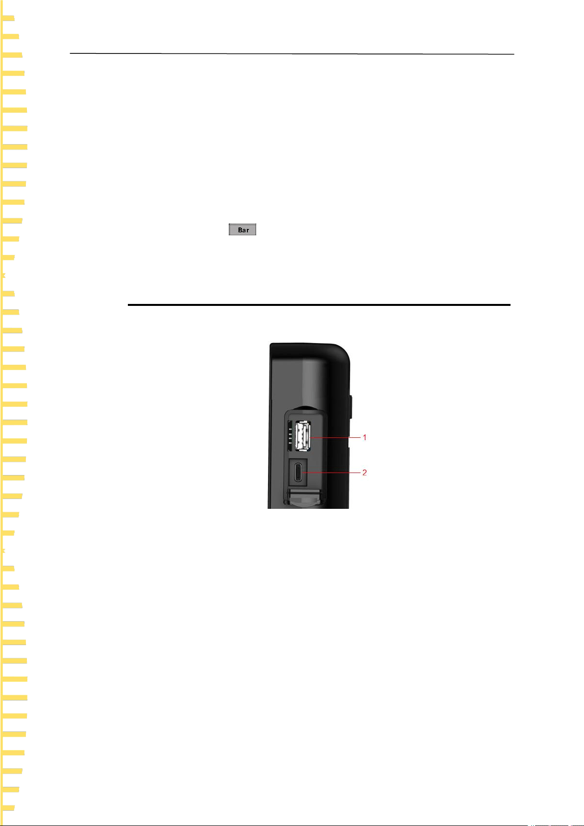
4.3.5 Test terminal connection
Figure 4.3 Test interface
1 + represents connecting the positive end of the thermocouple
2 - represents connecting the negative end of the thermocouple
Note:
1. The isolation voltage between channels should not exceed 300VDC, otherwise
the instrument may be damaged.
2. The red connector of the thermocouple line is the positive end.
Quick Start
EN
HTM200 user manual Copyright Qingdao Hantek Electronics Co., LTD
14
4.3.6 Product Introduction
This chapter introduces the front and rear panels and the user interface of the device.
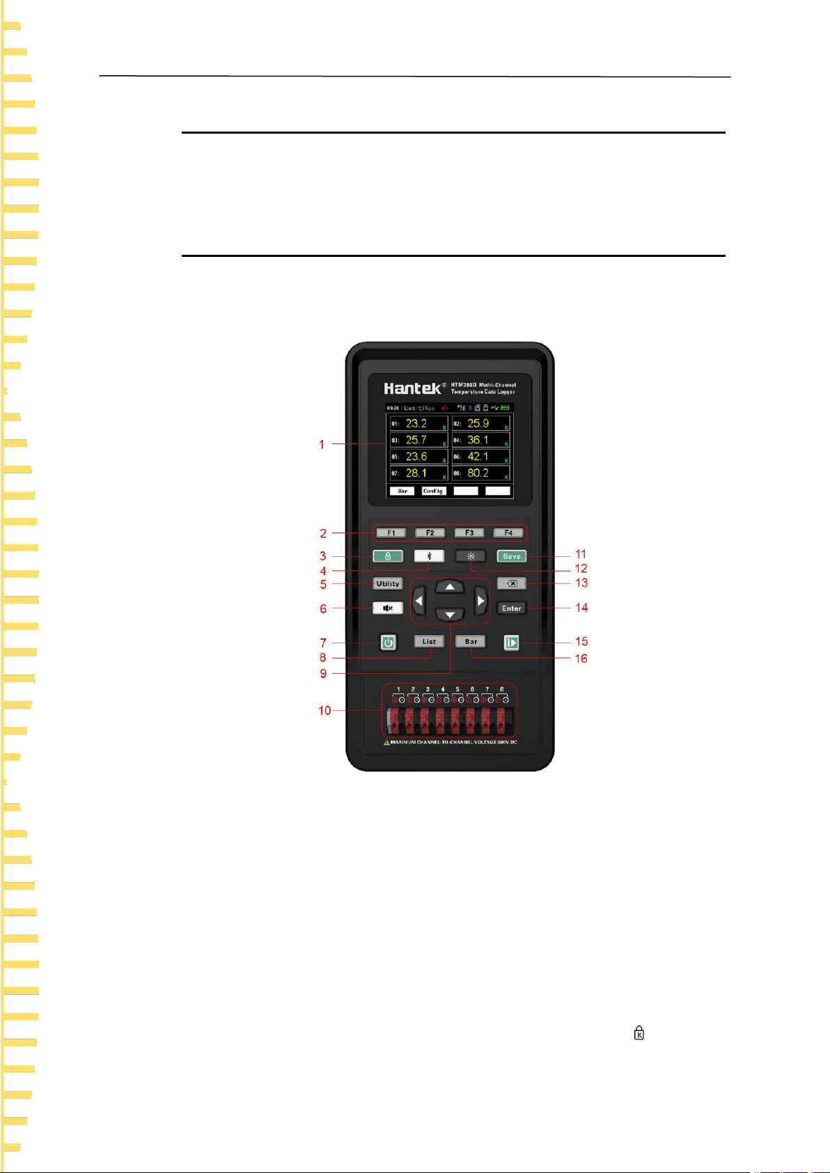
4.3.7 Front Panel Overview
Figure 4.4 Front panel
1 Display screen
2.8-inch TFT LCD screen.
2 Menu buttons
Corresponding to the four menus displayed at the bottom of the LCD.
3 Button lock
Press the button, the indicator light will be on and the button lock symbol will be

Quick Start
EN
Copyright Qingdao Hantek Electronics Co., LTD HTM200 user manual
15
displayed in the status bar. At this time, all buttons except this button and the power
button are disabled. Press this button again and all the buttons will be available again.
4 Bluetooth Switch
If the instrument supports Bluetooth communication, hold down the button for more
than 3 seconds, the backlight of the button will be on, and the Bluetooth symbol will
be displayed in the status bar, which indicates that the Bluetooth is enabled. Hold down
this button again for more than 3 seconds to turn off the Bluetooth function.
5 Auxiliary button
Press the button to enter the system menu, you can set users, save files and view
information.
6 Temperature upper limit and lower limit alarm control switch
The alarm function is turned on by default. When the measured temperature is higher
than the upper limit or lower than the lower limit, the buzzer will alarm (ringing). Press
the button, the backlight of the button will be on, the alarm closing symbol will be
displayed in the status bar, and the alarm function will be off. At this time, if the
measured temperature is higher than the upper limit or lower than the lower limit, the
buzzer will not alarm.
7 Power button
Press the button when shutdown, the instrument will start up. Press the button on state,
the instrument will turn off.
8 Measurement list shortcut button
In any interface, press button to quickly access the < List >page.
9 Direction buttons
Under the menu page or when entering a value, up, down, left and right arrow buttons
are used to change the cursor’s position. When changing the date and time, the up and
down arrow buttons are used to change the value, and the left and right arrow buttons
are used to change the cursor’s position.
10 Thermocouple connection end
11 Shortcuts for saving files
Quickly access the page for saving files.
12 Screen brightness shortcut button
Adjust screen brightness in a loop.
13 Delete button
Quick Start
EN
HTM200 user manual Copyright Qingdao Hantek Electronics Co., LTD
16
When entering a value, used to delete a number.
14 Enter button
When entering a value, used to enter the selected number.
15 Pause/Run button
When the backlight is green, the temperature updates in real time. Press the button and
the backlight will turn red, the temperature will stop updating.
16 Measuring bar chart shortcut button
In any interface, press to quickly enter the <Bar chart> page.
4.3.8 Side Panel Overview
Figure 4.5 Side panel
1 USB storage interface
Insert a USB flash drive (FAT32 format) to save the file.
2 Type - C interface
Connect type-c wire for charging and remote control.

Quick Start
EN
Copyright Qingdao Hantek Electronics Co., LTD HTM200 user manual
17
4.3.9 Top Panel Overview
Figure 4.6 Top panel
1 4G card slot
Insert a 4G card (Micro-SIM card, dimension: 15mm * 12mm). Only for models with 4G
module functions.
2 SD card slot
Insert a SD card (FAT32). Only for models with SD card function.
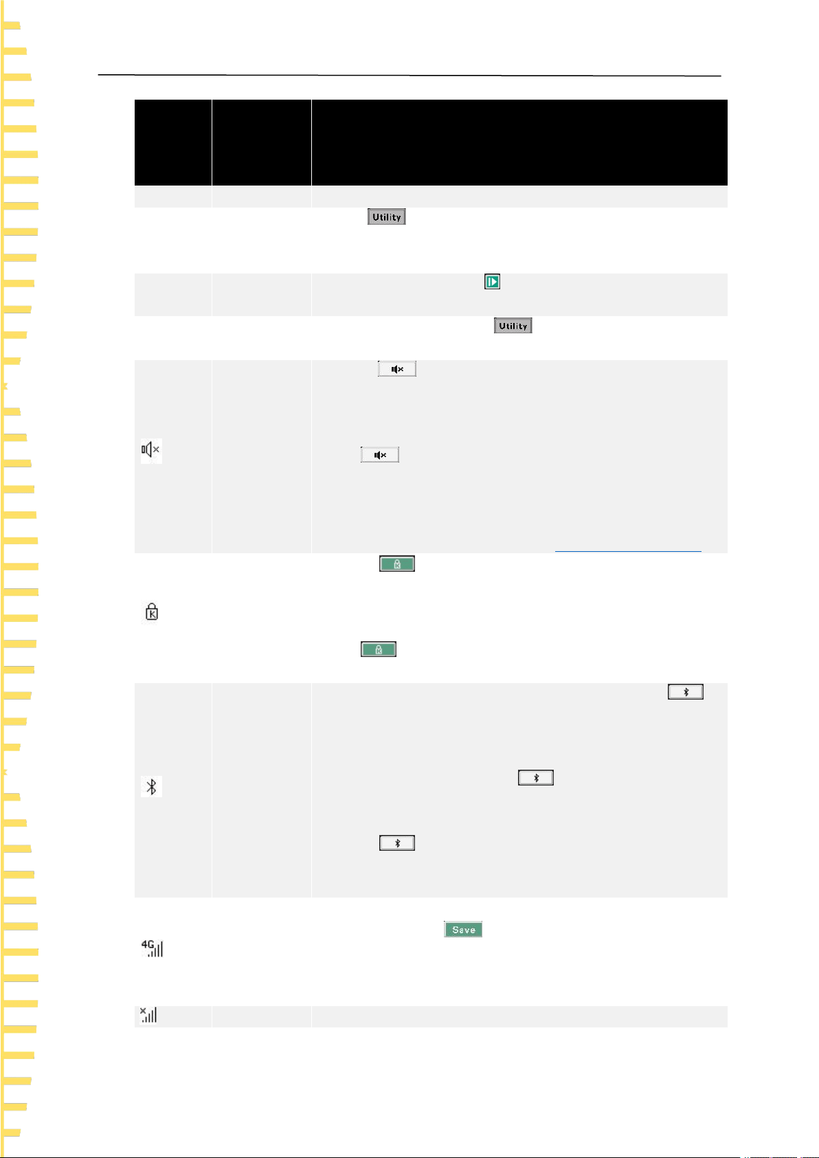
4.3.10 User Interface
Figure 4.7 User interface
1 Status display
Status
display
Mark
Instructions
Function introduction
EN
HTM200 user manual Copyright Qingdao Hantek Electronics Co., LTD
18
Status
display
Mark
Instructions
< List >
Page title
The page title
Time
Instrument
time
Press > User, enter the user menu to change the time.
When the battery is removed, the time and date will be restored
to original values.
Run
Running
state
Run and pause. Press at the lower right corner of the
instrument to change the running state.
Unit
Temperature
unit
Including ℃ and ℉. Press > User, enter the user menu
to change the unit.
Temperature
alarm
closing
symbol
Press , the backlight of the button will be on, and the
temperature alarm closing symbol will be displayed in the status
bar. At this time, even if the temperature is higher than the upper
limit or lower limit, the buzzer will not alarm.
Press again, the backlight of the button will be off and the
temperature alarm closing symbol will be hidden. At this time, if
the temperature is higher than the upper limit or lower than the
lower limit, the buzzer will alarm (ringing).
To set upper and lower limits, refer to
Channel configuration
.
Button lock
symbol
Press , the backlight of the button will be on, and the
button lock symbol will be displayed in the status bar. At this time,
only this button and power button are available, other buttons are
disabled.
Press again, the backlight of the button will be off, and the
button lock symbol will be hidden. All buttons resume available.
Bluetooth
symbol
If the product supports Bluetooth communication, press ,
the backlight of the button will be on, and the Bluetooth symbol
will be displayed in the status bar. The Bluetooth function is
turned on. If the product does not support Bluetooth
communication, when pressing , it will prompt "this model
doesn’t support this function", the backlight of the button will not
be on, and the Bluetooth symbol will not be shown.
Press , the backlight of the button will be off, and the
Bluetooth symbol will be hidden. The Bluetooth function will be
off.
4G symbol
If the product supports 4G network transmission, after inserting a
4G SIM card, press to enter the < File > page, then press
the upload soft button and hold down it for 3 seconds to open the
network transfer function. The 4G symbol will be displayed in the
status bar.
4G error
When some errors occur, such as SIM card missing, poor signal
Quick Start
EN
Copyright Qingdao Hantek Electronics Co., LTD HTM200 user manual
19
Status
display
Mark
Instructions
symbol
quality or no signal, SIM card arrearage, 4G module initialization
failure, etc., this symbol will be displayed in the status bar.
Data
transmission
When the 4G module is successfully initialized and the data is
being uploaded, the symbol will be displayed in the status bar.
SD card
symbol
If the product supports SD card storage, after the SD card is
inserted, the SD card symbol will be displayed in the status bar.
USB symbol
After a USB flash drive is inserted, the USB symbol will be
displayed in the status bar.
USB-type C
connection
symbol
When using USB-Type C interface for communication or
charging, the USB-Type C connection symbol will be displayed in
the status bar.
Surplus
electricity
prompt
Indicates the remaining electricity quantity. If the battery box is
red, it indicates that the battery is low. Charge the device in time.
Table 4.1 Status display
2 Function area
Press the function buttons or menu buttons to enter the corresponding function interface.
3 Menu area
Press to select the corresponding menu.
4.4 Storage and replacement of batteries
4.4.1 Battery storage
Lithium-ion batteries can be stored in clean, dry and ventilated rooms. Avoid contact
with corrosive substances and keep away from fire and heat sources.
If the instrument is not used for a long time (such as more than 6 months), the battery
should be charged 50% to 70% and be removed from the instrument to store in a dry
and cool environment.
If the lithium battery appears broken, rust, leakage, swelling, etc., it needs to be taken
out immediately and scrapped.
Quick Start
EN
HTM200 user manual Copyright Qingdao Hantek Electronics Co., LTD
20
4.4.2 Battery replacement
Batteries can be recharged, but they are easily consumable. If the standby time is
greatly reduced, you need to replace the battery. The specification of the battery is
18650 lithium battery, 3.7V, 2600mA.
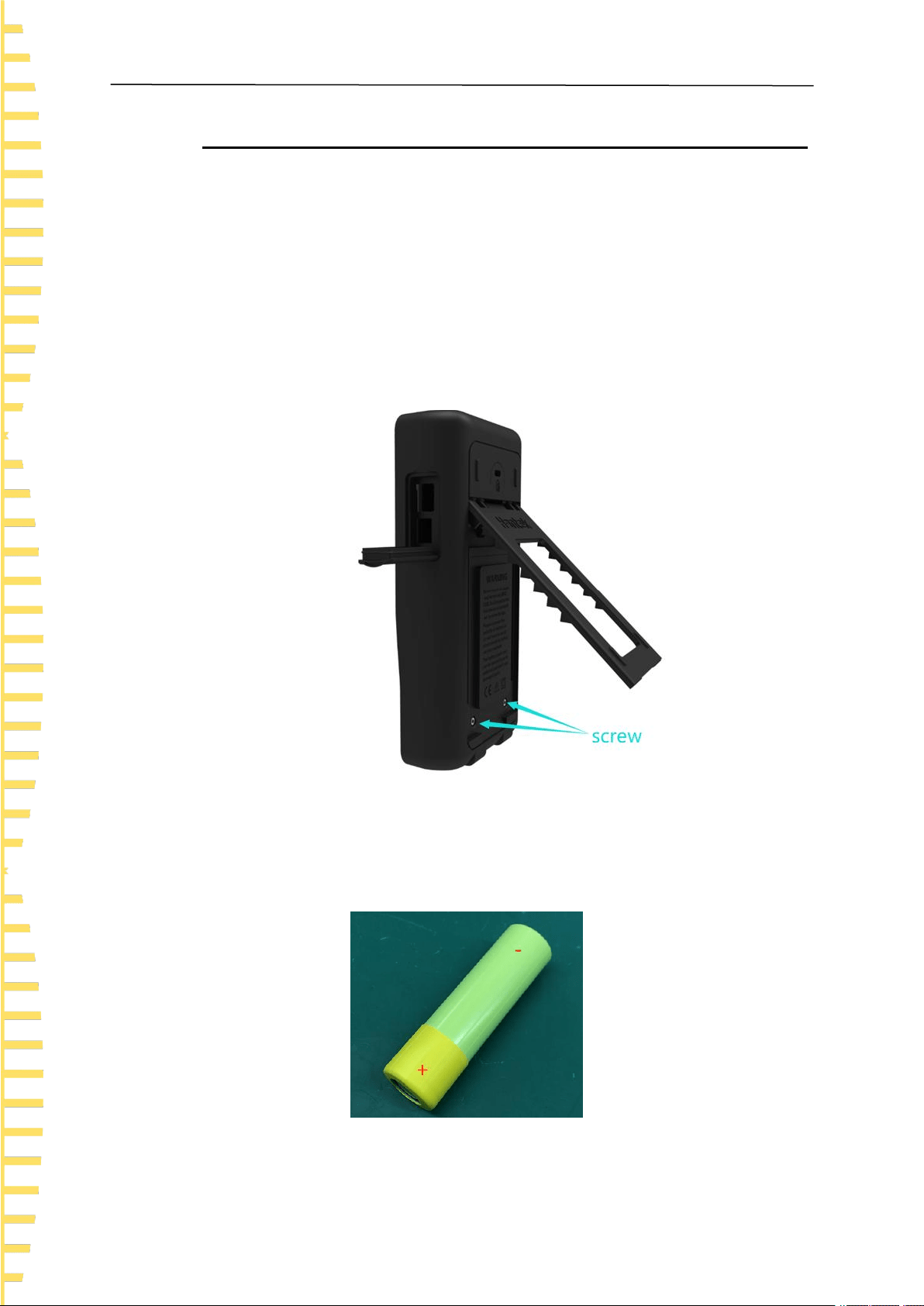
Please refer to the following steps to replace:
1 Open the standing, you can see two screws. Remove the screws and remove the
battery cover to see the battery.
Figure 4.8 Open the stand
2 Take out the battery from the negative pole, and then take out the battery after
the negative pole leaves.
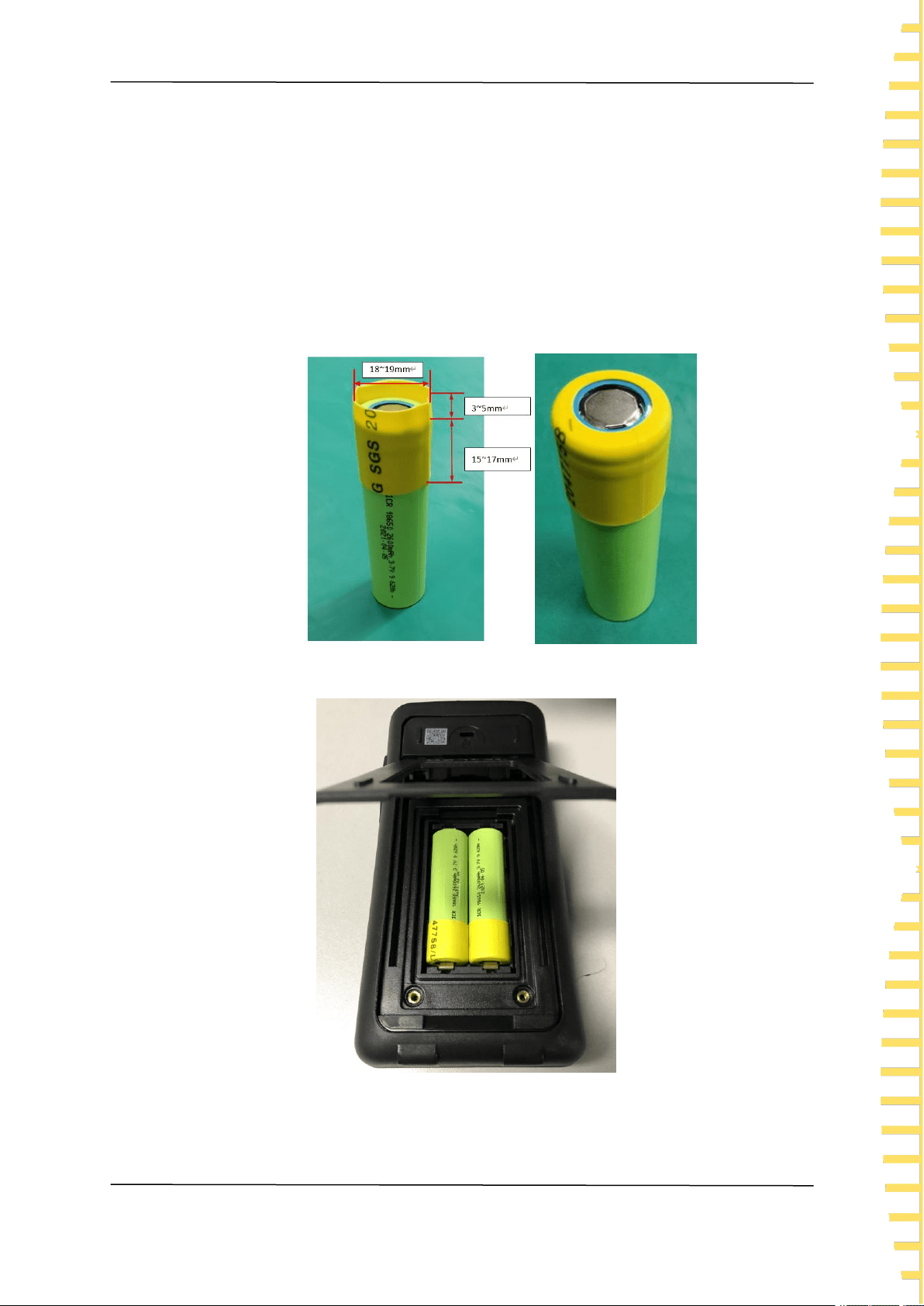
3 When installing the battery, ensure that the positive terminal of the battery has
Quick Start
EN
Copyright Qingdao Hantek Electronics Co., LTD HTM200 user manual
21
an insulation tube. Otherwise, install the insulation heat shrink tube by referring to
the following steps.
1) Prepare an insulation heat shrink tube of the following sizes.
Heat shrink tube dimension: thickness 0.2~0.3mm, inner diameter 18~19mm, length
21mm.
2) Place it on the positive pole of the battery.
3) Set the temperature of a heat gun to 270°, then blow on the heat shrink tube for 5
seconds to make the heat shrink tube stick to the battery.
4 Install the battery.
Figure 4.9 Install the battery
Note: When replacing the battery, pay attention to the positive and negative
Quick Start
EN
HTM200 user manual Copyright Qingdao Hantek Electronics Co., LTD
22
terminals of the battery.
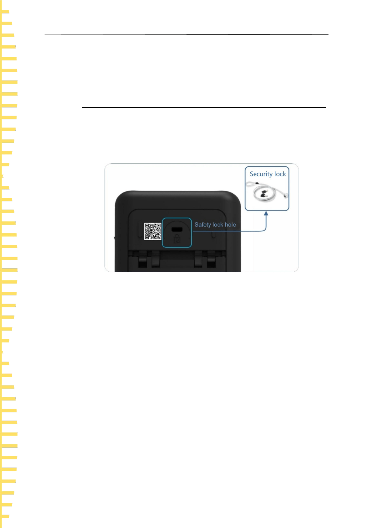
4.5 Safety lock hole
The safety lock hole is reserved on the back cover of the instrument, and the user
needs to buy the safety lock by himself. Wrap one end of the safety lock around a
hard-to-move object. Insert the other end into the safety lock. Turn the key clockwise to
lock the instrument and remove the key to meet the most basic anti-theft requirements.
Figure 4.10 Safety lock hole

Function introduction
EN
Copyright Qingdao Hantek Electronics Co., LTD HTM200 user manual
23
5 Function introduction
5.1 Measurement list
The instrument will enter < List > after startup. If you are on any other page, you
can enter the < List > page by pressing .
The < List > page mainly highlights the measurement results. At the same time, change
the font color to display the current sorting results. When the measured temperature is
above the upper limit or below the lower limit, the color of the temperature value on the
< List > page will turn red.
The display page is shown as following:
Figure 5.1 Measurement list
1 Number of channels
2 Temperature value
3 Type of thermocouple
5.2 Measurement bar chart
After the instrument is started, enter <List>. Then press the bar chart button to
enter < Bar chart >. If you are on any other page, you can just press to enter
the < Bar chart > page.
The < Bar chart > page mainly highlights the proportion of the measurement results to
the limit value.

Function introduction
EN
HTM200 user manual Copyright Qingdao Hantek Electronics Co., LTD
24
The display page is shown as following:
Figure 5.2 Measurement bar chart
5.3 Channel configuration
All settings on the < Configuration > page will be saved automatically at shutdown
and loaded automatically at next startup.
Press or to enter the < List > or < Bar chart >, and then press the
configuration button to enter the < Configuration > page.
use arrow buttons to select the configurations that you want to modify.
Configurations descriptions:
Configuration
item
Descriptions
Type
The thermocouple types include J/K/T/E/S/N/B/R/A/C/D. The initial is
type K.
Enable
Open or close channels.
Upper limit
Set the upper temperature limit. The initial value is 1800. When the
temperature is higher than the upper limit, the color of the temperature
values on the < List > page will turn red, and a buzzer alarm will be
sounded.
The upper limit value can be set ranges from -200 ° C to 2480 ° C.
Lower limit
Set the temperature lower limit. The initial value is -200. When the

Function introduction
EN
Copyright Qingdao Hantek Electronics Co., LTD HTM200 user manual
25
Configuration
item
Descriptions
temperature is below the lower limit, the color of the temperature
values on the < List > page will turn red, and a buzzer alarm will be
sounded.
The lower limit value ranges from -200 ° C to 2480 ° C.
Revised
value
Allows the user to modify the temperature of each channel.
The available value ranges from -99.9 ° C to 999.9 ° C.
Table 5.1 Channel configuration descriptions
Function menu Description:
Menu item
Descriptions
Edit
Edit the parameter of the selected configuration item.
Reset
Restore the parameter of the selected configuration item to its initial
values.
Flip up/down
Turn the page.
Return
Exit the <Configuration> page and return to the <List> page.
Table 5.2 Function menu descriptions
5.4 System settings
All settings on the < System > page will be automatically saved at shutdown and
loaded automatically at next startup.
Press to enter the < System > page.
5.4.1 User
Press > User to enter the < User > page, use the up or down arrow buttons
to select the corresponding function, and then press the Edit button to change the
corresponding settings.

Function introduction
EN
HTM200 user manual Copyright Qingdao Hantek Electronics Co., LTD
26
On the user settings page, you can set the system language, backlight brightness,
automatic shutdown, button sound, temperature unit and date and time.
User menu table:
Function
Settings
Descriptions
Language
selection
Chinese
English
Set the menu language.
Backlight
brightness
30%
50%
70%
100%
Set the screen backlight brightness.
You can also use shortcut button to quickly
adjust screen brightness.
Backlight
time
30 s
60 s
90 s
120 s
OFF
Set the screen backlight time. The screen will dim after
the button is not operated for a specified period of time.
Automatic
shutdown
5 min
10 min
30 min
OFF
Set the automatic shutdown time. The instrument will
shut down automatically after the button is not operated
for a specified period of time.
Button sound
ON
OFF
Turn on or off the button sound.
Temperature
unit
℃
℉
Choose Celsius as unit.
Choose Fahrenheit as unit.
Date and
time
- -
When the battery is removed, the time and date are
restored to their original values.
Table 5.3 User menu table
5.4.2 File
Users can save temperature data in real time to USB memory or Micro SD card
(optional).
Press > File to the < File > page. If you are on any other page, you can just
press to quickly enter the < File > page.

Function introduction
EN
Copyright Qingdao Hantek Electronics Co., LTD HTM200 user manual
27
File menu table:
Function
Settings
Descriptions
File name
- -
The file name is automatically generated when the USB
flash drive or SD card is inserted.
Storage
device
U disk
SD card
When inserting a USB flash drive or SD card, select the
corresponding storage device. The SD card storage
function is optional.
Time
interval
10 s
30 s
1 min
10 min
30 min
60 min
Set the interval for saving temperature data to a USB
flash drive or SD card.
4G interval
10 s
30 s
1 min
10 min
30 min
60 min
Set the interval for uploading temperature data to the
network.
Table 5.4 File menu table
Function menu descriptions:
Menu item
Descriptions
Edit
Edit the parameters of selected items.
Start
Start saving data, and automatically enter the < List > page.
Upload
Hold down the soft button for 3 seconds to enable the 4G network
transmission function. After the network transmission function is
enabled, all other buttons are disabled except the power button
and the alarm button . Hold down the Return soft button for 3
seconds to disable the network transmission function.
Return
Exit the < File > page and return to the < System > page.
Table 5.5 Function menu descriptions
Steps to save data files
1 Insert a MicroSD card or USB memory.
2 Press to enter the < File > page.
3 Select USB flash drive or SD Card.
4 Set the time interval.
Time interval options: 5 s, 30 s, 1 min, 10 min, 30 min, 60 min.
5 Press the start button, the instrument will start recording data, and the < List > page
Function introduction
EN
HTM200 user manual Copyright Qingdao Hantek Electronics Co., LTD
28
will be automatically displayed. Long press the stop button and hold down for 3
seconds to stop.
Document descriptions
1 File Name example
When inserting the memory, the time is: 2021-11-02 13:50:35. At this time, the file name
has already been generated in the format of 021350.CSV.
The file name won’t change if the storage is not disconnected. Start button can be
triggered multiple times, temperature data will be saved in the same file.
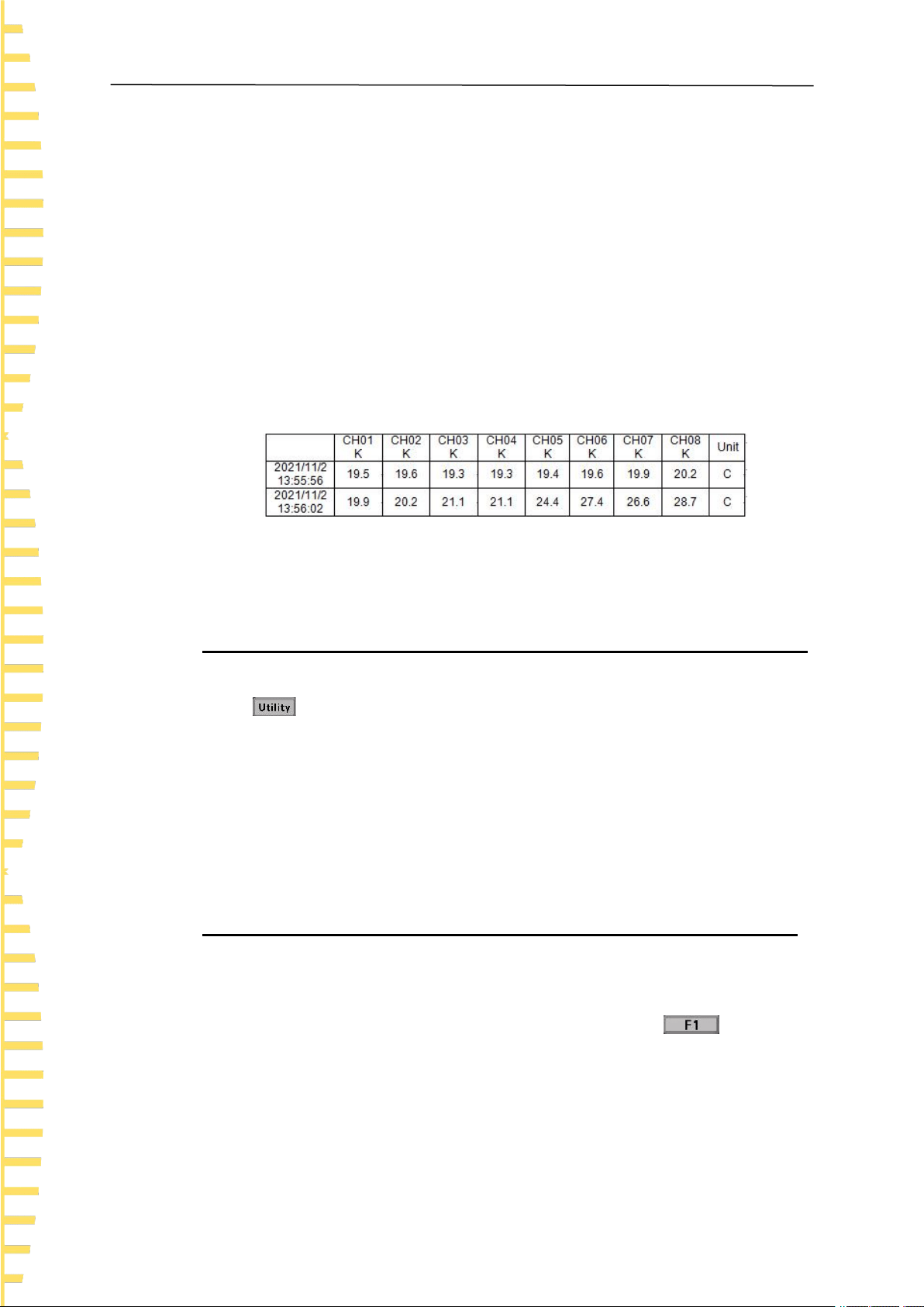
2 Data
The data consists of two parts, recording time and corresponding channel temperature.
The data format is float and one digit after the decimal point is reserved. Channels are
separated by “,”.
Figure 5.3 Data preservation instance
Note: The instrument only saves temperature data under the < List > page.
5.4.3 Service
Press > Service to enter the <Service> page to view the device model and
version information.
Note: Calibration is not available to users.
5.5 Firmware update
1. Download and install DfuSe Demo V3.0.5. Download the upgrade package (***.dfu).
2. In the shutdown state, insert the USB cable into the Type C port of the instrument,
and connect the instrument with the computer. Keep holding down . Press the
power button and release it. At this time, the indicator light at the lower right corner
starts flashing red and green, indicating that the instrument has entered Dfu mode.
Release F1.

Function introduction
EN
Copyright Qingdao Hantek Electronics Co., LTD HTM200 user manual
29
5.6 Error code description
Error code
Descriptions
ERROR1
The temperature is out of the current thermocouple testable range.
Please refer to the Data Manual of this series for details of measuring
ranges of different thermocouples.
ERROR2
The cold end temperature is abnormal.
Table 5.6 Error code descriptions

Remote control and data transmission
EN
HTM200 user manual Copyright Qingdao Hantek Electronics Co., LTD
30
6 Remote control and data
transmission
There are basically three ways to remotely control the instrument as followings:
User defined programming
Users can program to control the instrument using Standard Commands for
Programmable Instruments (SCPI). For detailed instructions on commands and
programming, refer to the Programming Manual of the series.
Use PC software or Android apps
Users can use the PC software or Android applications of this series to remotely control
the instrument.
Network data transmission
This product supports network data transmission. Users can realize communication
between the instrument and PC terminal or Android mobile terminal through 4G network
module.
The instrument supports communication with computer through USB interface,
Bluetooth module and 4G network module. Remote control is based on the Standard
Commands for Programmable Instruments (SCPI) command set.
This chapter will introduce how to use the corresponding software to control the
instrument remotely through various interfaces.
Note:
Before connecting the communication cable, shut down the device to avoid
damaging the communication interface of the device.
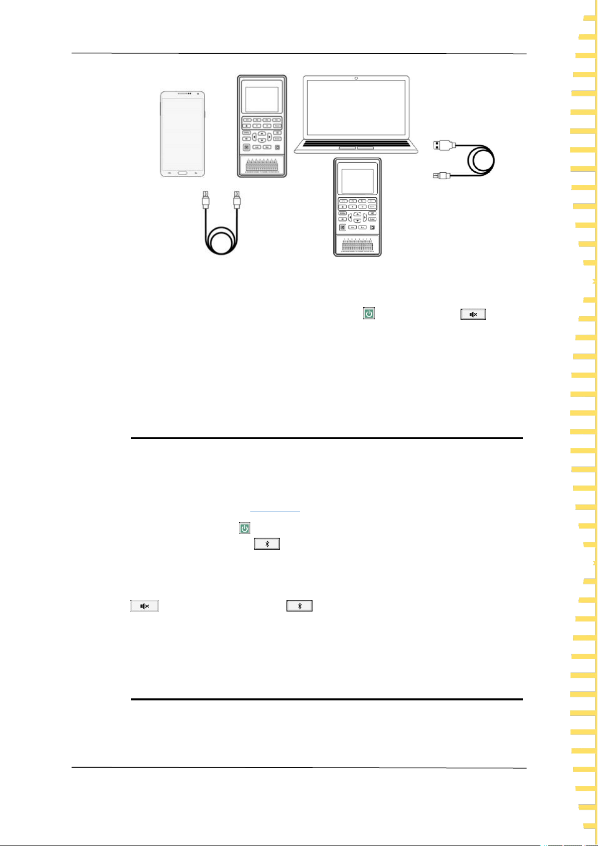
6.1 Control via USB
Press the power button to turn on the instrument.
Use the USB cable to connect the instrument to an Android phone or a Windows
computer to carry out USB communication.
Remote control and data transmission
EN
Copyright Qingdao Hantek Electronics Co., LTD HTM200 user manual
31
Figure 6.1 USB connection diagram
When Windows software or Android application communicates with the instrument
through USB connection, the instrument enters the USB connection mode. At this time,
all buttons are disabled except for the power button and alarm button . After
the USB cable is disconnected, the instrument exits the USB connection mode, and all
buttons are restored to use.
When the instrument is connected to a Windows computer, the user can use SCPI
instructions for remote control. Please refer to the Programming Manual of this series.
6.2 Control via Bluetooth
Only the instrument with Bluetooth function supports Bluetooth data transmission.
For specific models, see
model list
.
Press the power button to turn on the instrument.
Press the Bluetooth button and hold down for 3 seconds to enable Bluetooth
function.
After the Bluetooth function is enabled, the instrument enters Bluetooth remote mode.
At this time, all buttons are disabled except for the power button and alarm button
. Press the Bluetooth button again and hold down for 3 seconds to turn off
the Bluetooth function, and all the buttons will be restored to use.
The Bluetooth name corresponding to the instrument is HTM-XXXXXX.
Bluetooth communication protocol: Support BLE4.2 protocol, backward compatibility.
6.3 Network data transmission
The instrument with 4G (universal) module supports universal 4G function

Remote control and data transmission
EN
HTM200 user manual Copyright Qingdao Hantek Electronics Co., LTD
32
transmission. The instrument with 4G (domestic) module supports domestic 4G
function transmission. For specific models, see
model list
.
When communicating with the instrument over a network device, the user needs to
know the serial number (SN) and ID of the instrument.
Ways to view the SN and ID:
Press on the front panel and the service button to view the SN and ID of the
instrument. SN is the serial number of the current device. The SN and ID of the
instrument can also be seen on the display screen after the 4G module is activated.
Press the power button to turn on the instrument.
Press to enter the < File > page.
Press arrow buttons to select 4G Interval and press the Edit button to
change the 4G transmission interval. The interval can be 10 seconds, 30 seconds, 1
minute, 10 minutes, 30 minutes, or 60 minutes.
Press the upload button and hold down for 3 seconds to enable 4G network
transmission. After the network transmission function is enabled, all buttons except the
power button and the alarm button are disabled. Press the return button
and hold down for 3 seconds to turn off the network transmission function.
Note: Before enabling 4G network transmission function, ensure that the SIM card has
been inserted.
Symbols
Descriptions
4G symbol
If the product supports 4G transmission, after inserting a 4G
SIM card, press to enter the < File > page and then
press the upload button and hold down for 3 seconds to
open the network transmission function. The 4G symbol will
be displayed in the status bar.
4G error
symbol
When some errors occur, such as SIM card missing, poor
signal quality or no signal, SIM card arrearages, 4G module
initialization failure, etc., the 4G error symbol will be
displayed in the status bar.
Data
transmission
When the 4G module is successfully initialized and the data
is being uploaded, the symbol will be displayed in the status
bar.
Table 6.1 Network connection status symbols
When the 4G module and the remote communication mode is enabled, the SN and ID
will be displayed on the page.
The instrument will upload temperature data to the background server at a set interval
and frequency.
Holding down the exit button will disable the 4G network transmission function.

Android application
EN
Copyright Qingdao Hantek Electronics Co., LTD HTM200 user manual
33
7 Android application
7.1 Application download and installation
Users can download the instrument's Android mobile application from Hantek's
official website:
http://hantek.com.cn/products/detail/12273
It can also be downloaded by scanning the QR code on the back of the instrument.
Figure 7.1 Application download QR code
Use an Android phone to install the application of the instrument, and the icon will
be displayed on the phone desktop after installation.

Android application
EN
HTM200 user manual Copyright Qingdao Hantek Electronics Co., LTD
34
7.2 Application introduction
7.2.1 Main interface
Figure 7.2 Main interface of the Android application
1. Time
2. Channel
3. Line chart
4. Histogram
5. Home button
6. Unit
7. Pause/Run button
8. page setting button
A. Gently point the channel on the screen and slide left and right, and the channel will
move with the finger.
B. Gently point any position of the main interface on the screen and slide up and down.
The main interface will move with the finger. The user can choose to view the line chart
or bar chart.
C. Gently click any channel to open the channel setting window. You can set alarm

Android application
EN
Copyright Qingdao Hantek Electronics Co., LTD HTM200 user manual
35
upper limit, alarm lower limit, channel name and thermocouple type. Click the save
button to download the alarm upper limit, alarm lower limit and thermocouple type to the
instrument. The channel names displayed by the application will also change.
Figure 7.3 Channel settings
7.2.2 Setting Interface
Figure 7.4 Android application setting interface
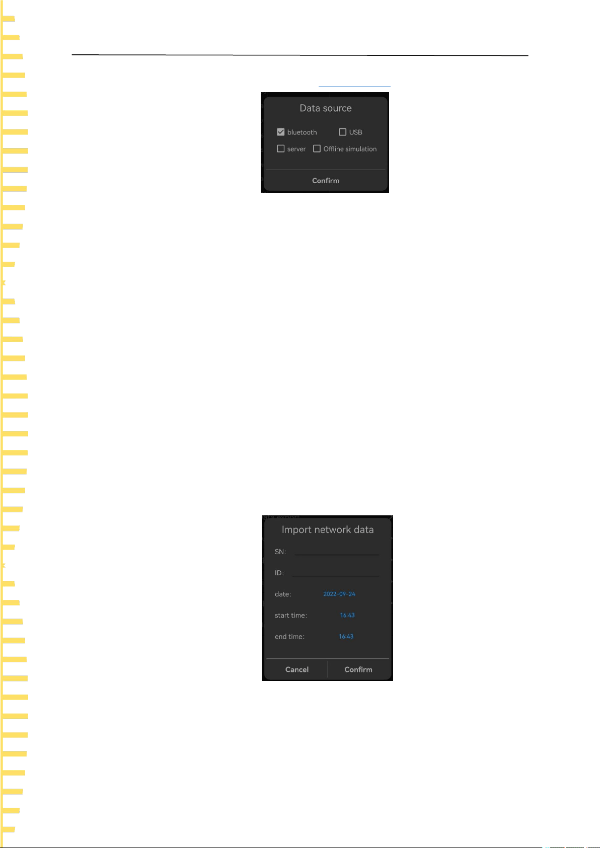
Data source
Data source includes Bluetooth, USB, network device and offline simulation. For details
Android application
EN
HTM200 user manual Copyright Qingdao Hantek Electronics Co., LTD
36
about how to open each data source, see
remote control
.
Figure 7.5 Data source selection
A. If Bluetooth is selected as the data source, search for the Bluetooth device and
select it (the Bluetooth name of the device is HTM-XXXXXX). You will enter the main
interface of the application program after connecting with the instrument successfully.
B. If USB is selected as data source, allow the temperature recorder to access the USB
device. You will enter the main interface of the application program after connecting
with the instrument successfully.
C. If network device is selected as the data source, input the correct SN and ID, and
click the OK button. The application will obtain all the temperature data uploaded by the
instrument on that day and the latest data in time.
D. If offline simulation is selected as the data source, the temperature displayed is
simulated random data. Users can perform “Import Server Data” and “Import Data Files”
anytime offline to view historical data.
Import server data
Enter the correct SN and ID, set the date, start time, and end time, and click OK. The
application will prompt "Data import succeeded", and the temperature data will be
displayed in the line chart on the home page. The settable time range can be any time
range before the current time when temperature data is available. If the temperature
data is empty during the specified period, the temperature data cannot be imported.
Figure 7.6 Import network data
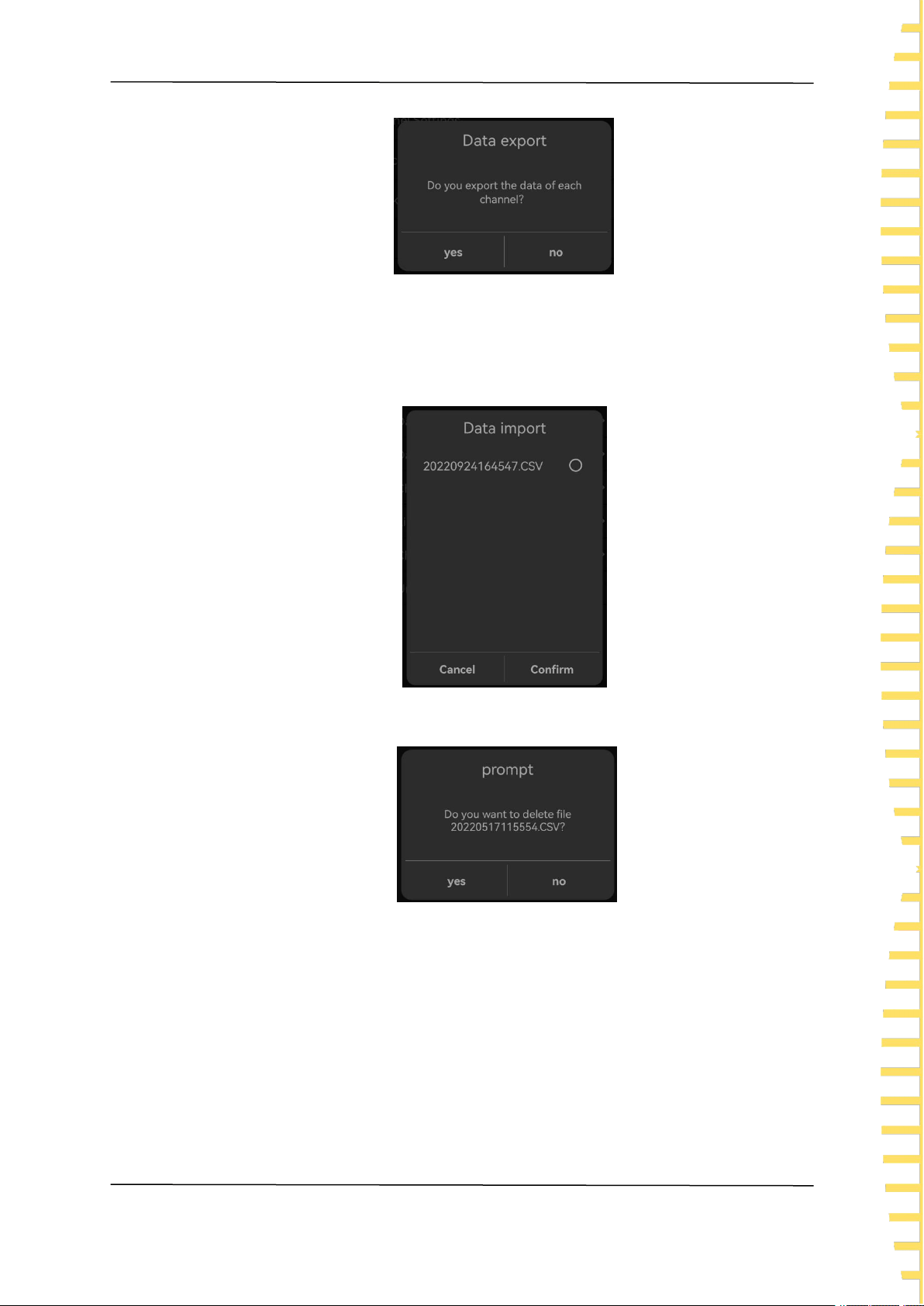
Data file export
Save the recorded temperature Data to the internal memory of the mobile phone in .csv.
The file path is Thermodetector/Data.
Android application
EN
Copyright Qingdao Hantek Electronics Co., LTD HTM200 user manual
37
Figure 7.7 Data file export
Data file import
Select the saved file and click "OK" to import the temperature data and display them on
the line chart.
Figure 7.8 Data file import
To delete the file, tap the file name and hold for 2s.
Figure 7.9 Delete file
Channel settings
You can open or close any channel, click "Save" to close the channel of the instrument,
and the channel will not be displayed on the home page.

Android application
EN
HTM200 user manual Copyright Qingdao Hantek Electronics Co., LTD
38
Figure 7.10 Channel settings
Line chart settings
You can set the range of X and Y axes on a line chart. The X axis is time and the Y axis
is temperature.
Figure 7.11 Line chart settings
Check the update
Check whether the application is the latest version.
Unit
The unit can be set to ℃ and ℉.

Windows Software
EN
Copyright Qingdao Hantek Electronics Co., LTD HTM200 user manual
39
8 Windows Software
8.1 Software Download and Installation
The application software can be downloaded from the Hantek website:
http://hantek.com.cn/products/detail/12273
Also you can scanning the QR code on the back of the instrument and download
the software.
Application software installation
Double-click the Setup.exe file and follow the installation wizard to install it.
After the installation is complete, the software icon will be displayed on the desktop.
Driver software installation
Double-click the IOLibSuite_****. Exe file and follow the installation wizard to install.
After installation is complete, the IO icon will be displayed in the status bar at the
lower right corner of the computer.
Windows Software
EN
HTM200 user manual Copyright Qingdao Hantek Electronics Co., LTD
40
8.2 Software Functions
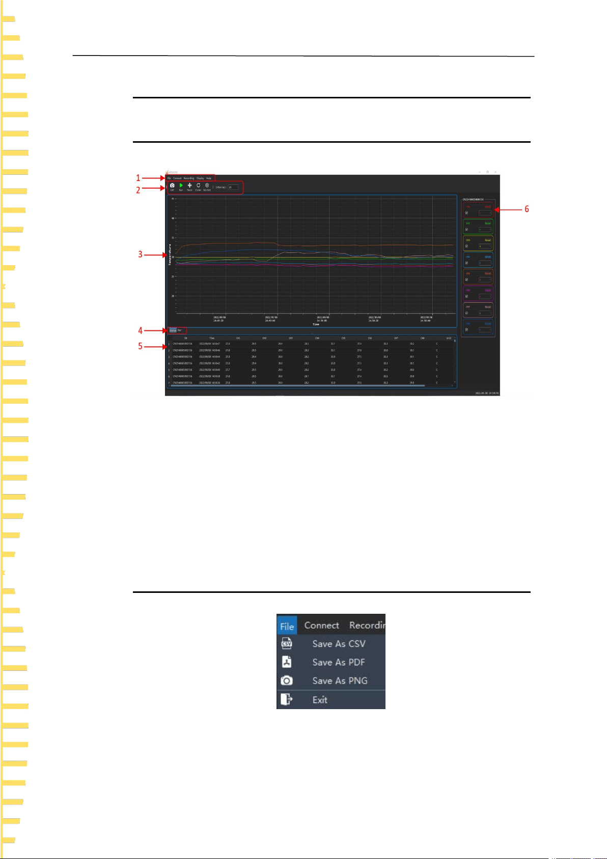
8.2.1 User Interface
Figure 8.1 Windows software user interface
1. Menu
2. Shortcuts
3. Temperature line chart
4. Switch button between line chart and bar chart
5. Temperature list
6. Channel settings
8.2.2 File Storage
Figure 8.2 File menu

Windows Software
EN
Copyright Qingdao Hantek Electronics Co., LTD HTM200 user manual
41
Saved as CSV
The temperature data can be saved as a .csv file for data analysis.
Screenshot saved as PDF
You can save the line chart or bar chart screenshot as a .pdf file.
Screenshot saved as PNG
You can save the line chart or bar chart screenshot as a .png file.
8.2.3 Connection Method
Figure 8.3 Connection menu
Connection modes include USB, Bluetooth, and network devices. For details, see
Remote Control.
USB connection
Connect the instrument to the computer. For the connection method, refer to Control
via USB.
After the instrument is successfully connected, double-click the IO icon in the status bar
at the lower right corner of the desktop to open "Keysight Connection Expert 2022", and
the device will be displayed in the window list.

Windows Software
EN
HTM200 user manual Copyright Qingdao Hantek Electronics Co., LTD
42
Figure 8.4 Communication connection window
Choose Connect > USB, the software will automatically connect the instrument and
collect temperature data.
Figure 8.5 Windows software data collection
Bluetooth connection
Turn on the Bluetooth function of the temperature recorder and use a computer with
Bluetooth function or a computer with Bluetooth adapter.
For the connection method, refer to
Control via Bluetooth
.
Support BLE4.2 protocol, backward compatibility.
Choose Connect > Bluetooth, the software will automatically find Bluetooth devices.
The Bluetooth name corresponding to the instrument is HTM-XXXXXX.
Windows Software
EN
Copyright Qingdao Hantek Electronics Co., LTD HTM200 user manual
43
Figure 8.6 Bluetooth connection
Select the Bluetooth device to be connected and click OK. The software will
automatically connect the device and collect temperature data.
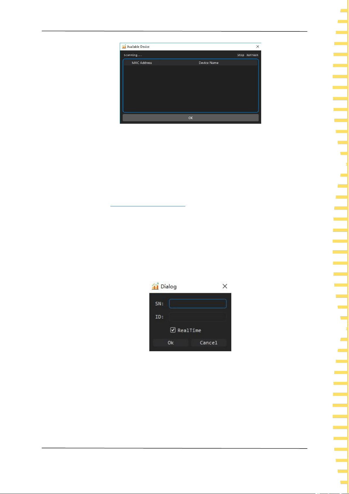
Network device connection
Enable 4G transmission function of the temperature recorder. For the connection
method, see
Network data transmission
.
When the screen of the temperature recorder shows "Remote communication mode
started", the instrument will start uploading data.
Choose Connect > Network Device, input the SN and ID of the instrument, and select
"Real-time Data". The software will obtain all the temperature data uploaded by the
instrument on that day and the latest data in time.
Choose Connect > Network Device, input the SN and ID of the instrument, and
deselect "Real-time Data". You can view the historical data uploaded by the instrument
on a previous day.
Figure 8.7 Viewing historical data
Offline simulation mode
When there is no connection, you can choose the offline simulation mode, and the
temperature data is the simulated random value.
Windows Software
EN
HTM200 user manual Copyright Qingdao Hantek Electronics Co., LTD
44
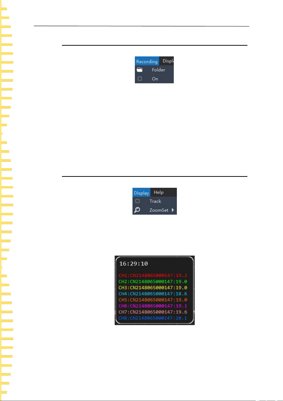
8.2.4 Record
Figure 8.8 Record menu
Folder
You can specify a path for saving the record file. The default path is the root directory of
the software installation.
ON
Select this menu to start recording and deselect to stop recording. The file format is .csv.
Each time you select this menu, a new file will be generated.
8.2.5 Display
Figure 8.9 Display menu
Track
Select this menu to turn on the tracking function, as shown below, to track the
temperature data at a certain point in time. Deselect to turn off tracking.
Figure 8.10 Track
Windows Software
EN
Copyright Qingdao Hantek Electronics Co., LTD HTM200 user manual
45
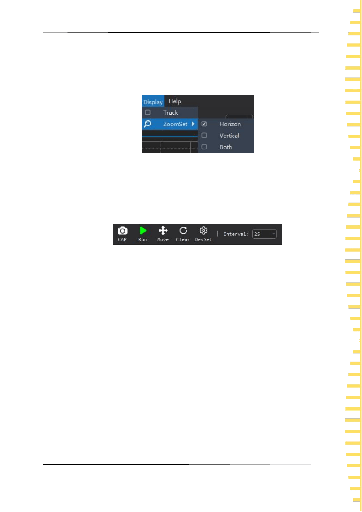
Zoom
You can choose horizontal direction, vertical direction or both.
If you scroll the mouse wheel down to enlarge the line chart and up to shrink the line
chart.
Figure 8.11 Zoom
8.2.6 Shortcuts
Figure 8.12 Shortcuts
Screenshot
Take a screenshot of the line graph or bar graph and save it as a .png file to the
computer.
Run/stop
Run or stop button.
Move
After selecting the button, you can use the mouse up, down, left and right to move the
line chart. Click the button again to turn off this function.
Reset
Click this button to clear all collected temperature data and line charts.
Settings
You can set the temperature unit of the selected device or remove the selected device.
Interval
Set the interval for software to obtain the temperature.

Windows Software
EN
HTM200 user manual Copyright Qingdao Hantek Electronics Co., LTD
46
8.2.7 Channel settings
Figure 8.13 Channel settings
1. Channel name: You can click to edit the channel name
2. Channel switch
3. Temperature lower limit
4. Temperature upper limit
5. Reset the channel name
6. Change the thermocouple type

Troubleshooting
EN
Copyright Qingdao Hantek Electronics Co., LTD HTM200 user manual
47
9 Troubleshooting
1. If you press the power button and there is still no display on the screen.
1) Check whether the battery is installed.
2) Check whether the battery voltage is higher than 3.4V.
3) After the above examination, restart the instrument.
4) If you still cannot start up the product normally, please contact Hantek.
2. The screen is too dark to see clearly.
1) Check whether the brightness of the LCD screen is too low. Press > User,
then press to select the backlight brightness. Press Edit to change the
LCD brightness to the appropriate value.
2) Check backlight time settings. Press > User, then press to
select the backlight time. Press Edit to change the screen backlight time.
3. The temperature value is incorrect.
1) Check whether the thermocouple type set by the instrument is consistent with the
thermocouple sensor used.
2) Check whether the thermocouple is installed correctly. The red connector of the
thermocouple sensor is the positive end.
4. The USB storage device cannot be recognized.
1) Check whether the USB device can work normally if connected to other instruments
or computers.
2) Confirm that the USB flash drive is FAT32 format device.
3) After restarting the instrument, insert the USB device again for inspection.
4) If it still doesn’t work, please contact Hantek.

Appendix
EN
HTM200 user manual Copyright Qingdao Hantek Electronics Co., LTD
48
10 Appendix
10.1 Appendix A: Accessories
This product provides the following accessories. User can obtain all accessories
from the local supplier.
Standard accessories:
• Power adapter
• USB cable
• Two Type K thermocouple test cables
• Product certificate

Address: Building 35, Lian Dong U Gu, No.780 Baoyuan Road, High-tech Zone, Qingdao, Shandong
Province
Switchboard: 400-036-7077
E-mail: service@hantek.com
Tel: 0532-55678770, 55678772, 55678773
Postcode: 266000
Website: www.hantek.com
Qingdao Hantek Electronics Co., LTD