
Owner's Manual
[RRFTSMRN
20.5 HP
ELECTRIC START
42" MOWER
AUTOMATIC
LAWN TRACTOR
Model No.
917.270840
• Safety
• Assembly
• Operation
• Maintenance
• Repair Parts
CAUTION:
Read and follow all
Safety Rules and Instructions
before operating this equip-
ment.
For answers to your questions
about this product, Call:
1-800-659-5917
Sears Craftsman Help Line
5 am - 5 pm, Mon- Sat
Sears, Roebuck and Co., Hoffman Estates, IL 60179
Warranty ................................................. 2
Safety Rules ........................................... 2
Product Specifications ........................... 5
Assembly ................................................ 8
Operation .............................................. 12
Maintenance Schedule ......................... 19
Maintenance ......................................... 19
Service and Adjustments ...................... 23
Storage ................................................. 29
Troubleshooting .................................... 31
Repair Parts ......................................... 34
Parts Ordering ....................... Back Cover
LIMITED TWO YEAR WARRANTY ON CRAFTSMAN RIDING EQUIPMENT
For two (2) years from the date of purchase, if this Craftsman Riding Equipment is main-
tained, lubricated and tuned up according to the instructions in the owner's manual,
Sears will repair or replace, free of charge, any parts found to be defective in material or
workmanship.
This Warranty does not cover:
• Expendable items which become worn during normal use, such as blades, spark
plugs, air cleaners, belts, etc.
• "Fire replacement or repair caused by punctures from outside objects, such as nails,
thorns, stumps, or glass.
• Repairs necessary because of operator abuse, negligence, improper storage or acci-
dent or the failure to maintain the equipment according to the instructions contained in
the owner's manual.
• Riding equipment used for commercial or rental purposes.
LIMITED 90 DAY WARRANTY ON BATTERY
For ninety (90) days from date of purchase, if any battery included with this riding equip-
ment proves defective in material or workmanship and our testing determines the bat-
tery will not hold a charge, Sears will replace the battery at no charge. In-home warranty
service on your Craftsman riding equipment is available at no charge for 30 days from
the date of purchase. Please contact your nearest service center. After 30 days from the
date of purchase, warranty service is available by taking your Craftsman riding equip-
ment to your nearest Sears Service Center. (In-home warranty service will still be avail-
able after 30 days from the date of purchase but a standard trip charge will apply). This
warranty applies only while this product is in the United States. This Warranty gives you
specific legal rights, and you may also have other rights which may vary from state to
state.
Sears, Roebuck and Co., D/817 WA, Hoffman Estates, IL 60179
GENERAL OPERATION
• Read, understand, and follow all instruc-
tions in the manual and on the machine
before starting.
• Only allow responsible adults, who are
familiar with the instructions, to operate
the machine.
• Clear the area of objects such as rocks,
toys, wire, etc., which could be picked
up and thrown by the blade.
• Be sure the area is clear of other people
before mowing. Stop machine if anyone
enters the area.
t-)
• Never carry passengers.
• Do not mow in reverse unless absolute-
ly necessary. Always look down and
behind before and while backing.
• Be aware of the mower discharge direc-
tion and do not point it at anyone. Do
not operate the mower without either
the entire grass catcher or the guard in
place.
• Slow down before turning.
• Never leave a running machine unat-
tended. Always turn off blades, set park-
ing brake, stop engine, and remove
keys before dismounting.
• Turn off blades when not mowing.
• Stop engine before removing grass
catcher or unclogging chute.
• Mow only in daylight or good artificial
light.
• Do not operate the machine while under
the influence of alcohol or drugs.
• Watch for traffic when operating near or
crossing roadways.
• Use extra care when loading or unload-
ing the machine into a trailer or truck.
SLOPE OPERATION
Slopes are a major factor related to loss-
of-control and tipover accidents, which
can result in severe injury or death. All
slopes require extra caution. If you cannot
back up the slope or if you feel uneasy on
it, do not mow it.
DO:
• Mow up and down slopes, not across.
• Remove obstacles such as rocks, tree
limbs, etc.
• Watch for holes, ruts, or bumps. Uneven
terrain could overturn the machine. Tall
grass can hide obstacles.
• Use slow speed. Choose a low gear so
that you will not have to stop or shift
while on the slope.
• Follow the manufacturer's recommen-
dations for wheel weights or counter-
weights to improve stability.
• Use extra care with grass catchers or
other attachments. These can change
the stability of the machine.
• Keep all movement on the slopes slow
and gradual. Do not make sudden
changes in speed or direction.
• Avoid starting or stopping on a slope. If
tires lose traction, disengage the blades
and proceed slowly straight down the
slope.
DO NOT:
• Do notturn on slopes unless necessary,
and then, turn slowly and gradually
downhill, if possible.
• Do not mow near drep-offs, ditches, or
embankments. The mower could sud-
denly turn over if a wheel is over the
edge of a cliff or ditch, or if an edge
caves in.
• Do not mow on wet grass. Reduced
traction could cause sliding.
• Do nottry to stabilize the machine by
putting your foot on the ground.
• Do not use grass catcher on steep
slopes.
CHILDREN
Tragic accidents can occur if the operator
is not alert to the presence of children.
Children are often attracted to the
machine and the mowing activity. Never
assume that children will remain where
you last saw them.
• Keep children out of the mowing area
and under the watchful care of another
responsible adult.
• Be alert and turn machine off if children
enter the area.
• Before and when backing, look behind
and down for small children.
• Never carry children. They may fall off
and be seriously injured or interfere with
safe machine operation.
• Never allow children to operate the
machine.
• Use extra care when approaching blind
corners, shrubs, trees, or other objects
that may obscure vision.
SERVICE
• Use extra care in handling gasoline and
other fuels. They are flammable and
vapors are explosive.
Use only an approved container.
Never remove gas cap or add fuel
with the engine running. Allow en-
gine to cool before refueling. Do not
smoke.
Never refuel the machine indoors.
Never store the machine or fuel
container inside where there is an
open flame, such as a water heater.
• Never run a machine inside a closed
area.
• Keep nuts and bolts, especially blade
attachment bolts, tight and keep equip-
ment in good condition.
• Never tamper with safety devices.
Check their proper operation regularly.
• Keep machine free of grass, leaves, or
other debris build-up. Clean oil or fuel
spillage. Allow machine to cool before
storing.
• Stop and inspect the equipment if you
strike an object. Repair, if necessary,
before restarting.
3
• Never make adjustments or repairs with
the engine running.
• Grass catcher components are subject
to wear, damage, and deterioration,
which could expose moving parts or
allow objects to be thrown. Frequently
check components and replace with
manufacturer's recommended parts,
when necessary.
• Mower blades are sharp and can cut.
Wrap the blade(s) or wear gloves, and
use extra caution when servicing them:
• Check brake operation frequently.
Adjust and service as required.
• Be sure the area is clear of other people
before mowing. Stop machine if anyone
enters the area.
• Never carry passengers.
• Do not mow in reverse unless absolute-
ly necessary. Always look down and
behind before and while backing,
• Never carry children. They may fall off
and be seriously injured or interfere with
safe machine operation.
• Keep children out of the mowing area
and under the watchful care of another
responsible adult.
• Be alert and turn machine off if children
enter the area.
• Before and when backing, look behind
and down for small children.
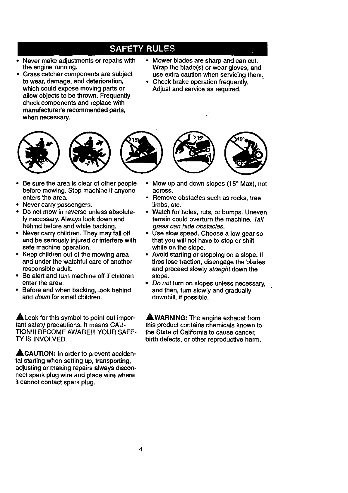
• Mow up and down slopes (15 ° Max), not
across.
• Remove obstacles such as rocks, tree
limbs, etc.
• Watch for holes, ruts, or bumps. Uneven
terrain could overturn the machine. Tall
grass can hide obstacles.
• Use slow speed. Choose a low gear so
that you will not have to stop or shift
while on the slope.
• Avoid starting or stopping on a slope. If
tires lose traction, disengage the blades
and proceed slowly straight down the
slope.
• Donotturn on slopes unless necessary,
and then, turn slowly and gradually
downhill, if possible.
_,Look for this symbol to point out impor-
tant safety precautions. It means CAU-
TION!!! BECOME AWARE!!! YOUR SAFE-
TY IS INVOLVED.
,_CAUTION: In order to prevent acciden-
tal starting when setting up, transporting,
adjusting or making repairs always discon-
nect spark plug wire and place wire where
it cannot contact spark plug.
,_.WARNING: The engine exhaust from
this product contains chemicals known to
the State of California to cause cancer,
birth defects, or other reproductive harm.
4
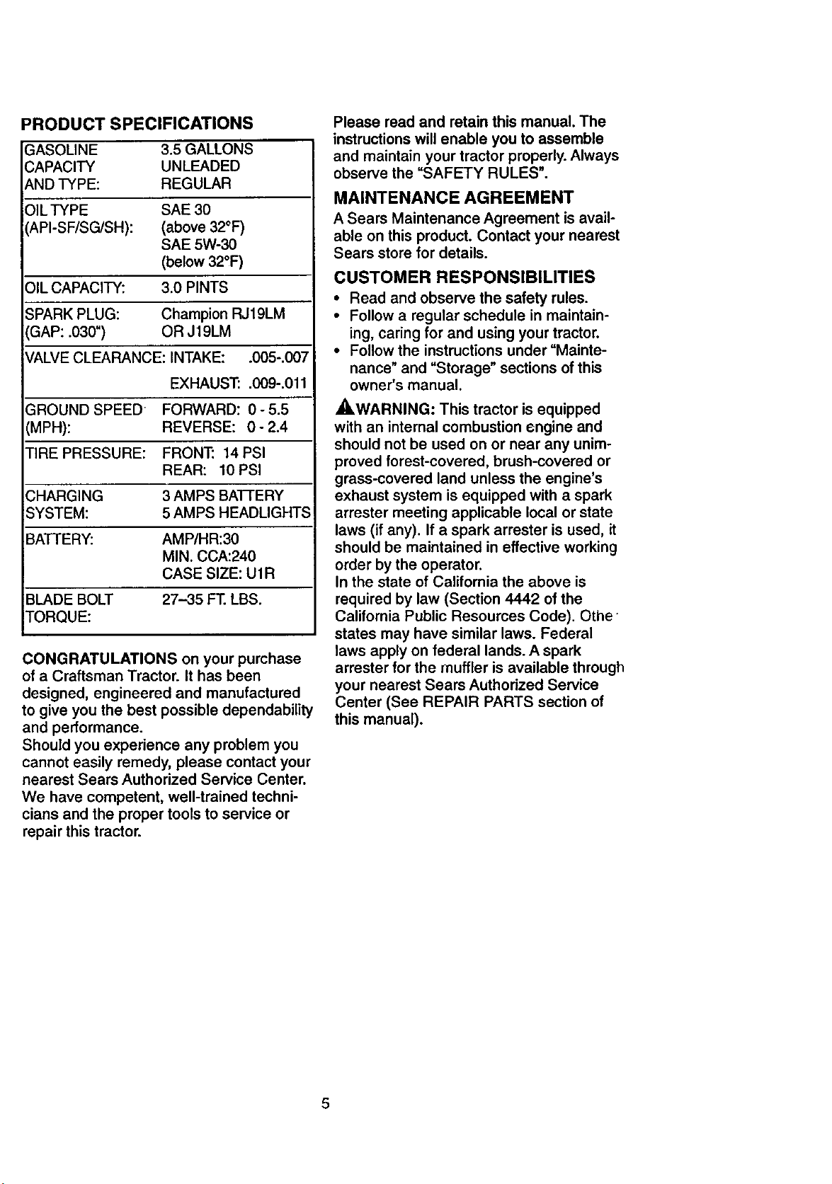
PRODUCT SPECIFICATIONS
GASOLINE 3.5GALLONS
CAPACITY UNLEADED
AND TYPE: REGULAR
OIL TYPE SAE 30
API-SF/SG/SH): (above 32°F)
SAE 5W-30
(below 32°F)
OIL CAPACITY: 3.0 PINTS
SPARK PLUG: Champion RJ19LM
GAP: .030") OR J19LM
VALVE CLEARANCE: INTAKE: .005-.007
EXHAUST: .009-.011
GROUND SPEED FORWARD: 0-5.5
(MPH): REVERSE: 0- 2.4
TIRE PRESSURE: FRONT: 14 PSI
REAR: 10 PSI
CHARGING 3 AMPS BATFERY
SYSTEM: 5 AMPS HEADLIGHTS
BATTERY: AMP/HR:30
MIN. CCA:240
CASE SIZE: U1R
BLADE BOLT 27-35 FT. LBS.
TORQUE:
CONGRATULATIONS on your purchase
of a Craftsman Tractor. It has been
designed, engineered and manufactured
to give you the best possible dependability
and performance.
Should you experience any problem you
cannot easily remedy, please contact your
nearest Sears Authorized Service Center.
We have competent, well-trained techni-
cians and the proper tools to service or
repair this tractor.
Please read and retain this manual. The
instructions will enable you to assemble
and maintain your tractor properly. Always
observe the =SAFETY RULES".
MAINTENANCE AGREEMENT
A Sears Maintenance Agreement is avail-
able onthis product. Contact your nearest
Sears store for details.
CUSTOMER RESPONSIBILITIES
• Read and observe the safety rules.
• Follow a regular schedule in maintain-
ing, caring for and using your tractor.
• Follow the instructions under "Mainte-
nance" and "Storage" sections of this
owner's manual.
_,WARNING: This tractor is equipped
with an internal combustion engine and
should not be used on or near any unim-
proved forest-covered, brush-covered or
grass-covered land unless the engine's
exhaust system is equipped with a spark
attester meeting applicable local or state
laws (if any). If a spark arrester is used, it
should be maintained in effective working
order by the operator.
In the state of California the above is
required by law (Section 4442 of the
California Public Resoumes Code). Othe
states may have similar laws. Federal
laws apply on federal lands. A spark
arrester for the muffler is available through
your nearest Sears Authorized Service
Center (See REPAIR PARTS section of
this manual).
5
©
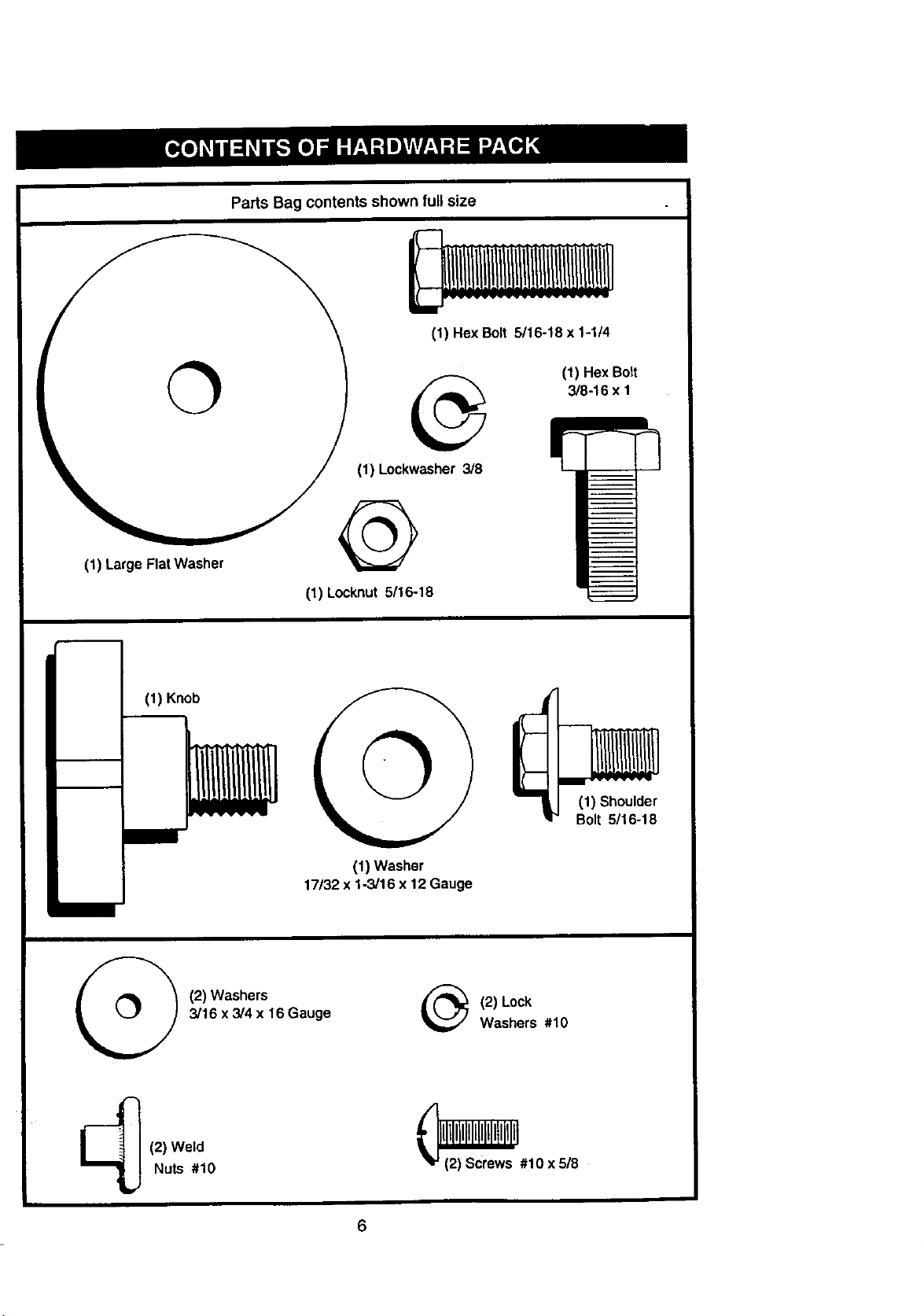
(1) LargeFlatWasher
Parts Bag contents shown full size
(1) Hex Bolt 5/16-18 x 1-1/4
(1) Hex Bolt
3/8-16 x 1
(1) Lockwasher3/8
@
(1) Locknut 5/16o18
(1) Knob
(1) Washer
17/32x 1-3/16 x 12 Gauge
(1) Shoulder
Bolt 5/16°18
(2) Washers
3/16 x 3/4 x 16 Gauge
_ (2) Lock
Washers #10
(2) Weld
Nuts #10
_#10 x 518
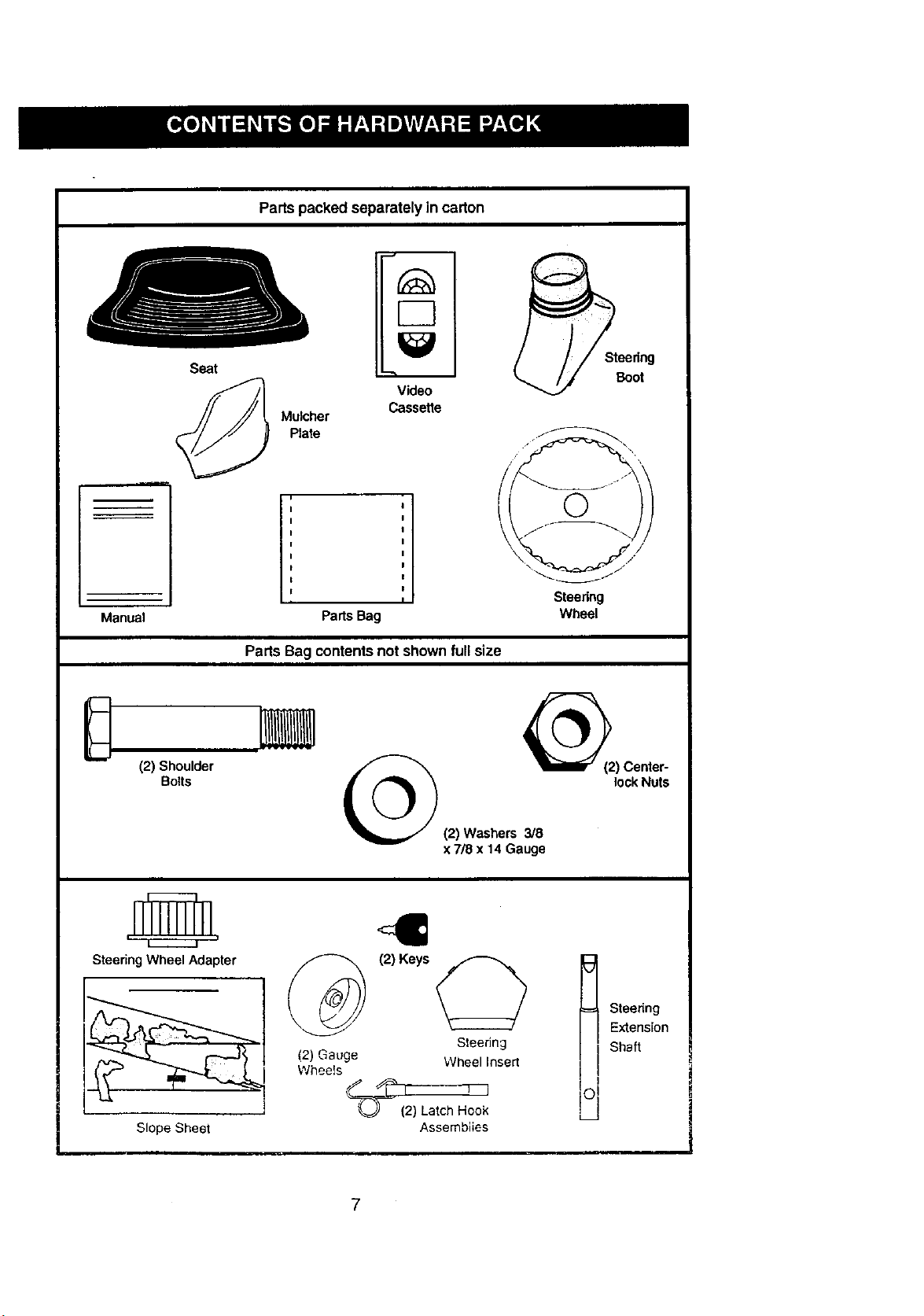
Parts packed separately in carton
Manual
Seat
EC]
Video
Cassette
Mulcher
Plate
Parts Bag
Paris Bag contents not shownfull size
\
Steedng
Wheel
Steering
Boot
(2) Shoulder
Bolts
2) Center-
lock Nuts
(2) Washers 3/8
x7/8 x 14 Gauge
Steering Wheel Adapter
Slope Sheet
(2) Gauge
Wheels
(2) Keys
Steedng
Wheel Insert
_(2 !_J
) Latch Hook
Assemblies
Steering
Extension
Shaft
7
Your new tractor has been assembled at the factory with exception of those parts left
unassembled for shipping purposes. To ensure safe and proper operation of your tractor
all parts and hardware you assemble must be tightened securely. Use the correct tools
as necessary to insure proper tightness. Review the video cassette before you begin.
TOOLS REQUIRED FOR
ASSEMBLY
A socket wrench set willmake assembly
easier. Standard wrench sizes you need
are listed below.
(1) 9/16" wrench
(1) 3/4" wrench
(2) 1/2" wrench
(1) Utility knife
(1)Pliers
(1) 3/4" Socket w/
drive rachet
(1) Phillips Screw-
driver
(1) Tire pressure
gauge
When right or left hand is mentioned in
this manual, it means, from your point of
view, when you are in the operating posi-
tion (seated behind the steering wheel).
TO REMOVE TRACTOR FROM
CARTON
UNPACK CARTON
• Remove all accessible loose parts and
parts boxes from shipping carton (See
page 6).
• Cut, from top to bottom, along lines on
all four corners of shipping carton, and
lay panels flat.
• Check for any additional loose parts or
boxes and remove,
BEFORE ROLLING TRACTOR OFF
SKID
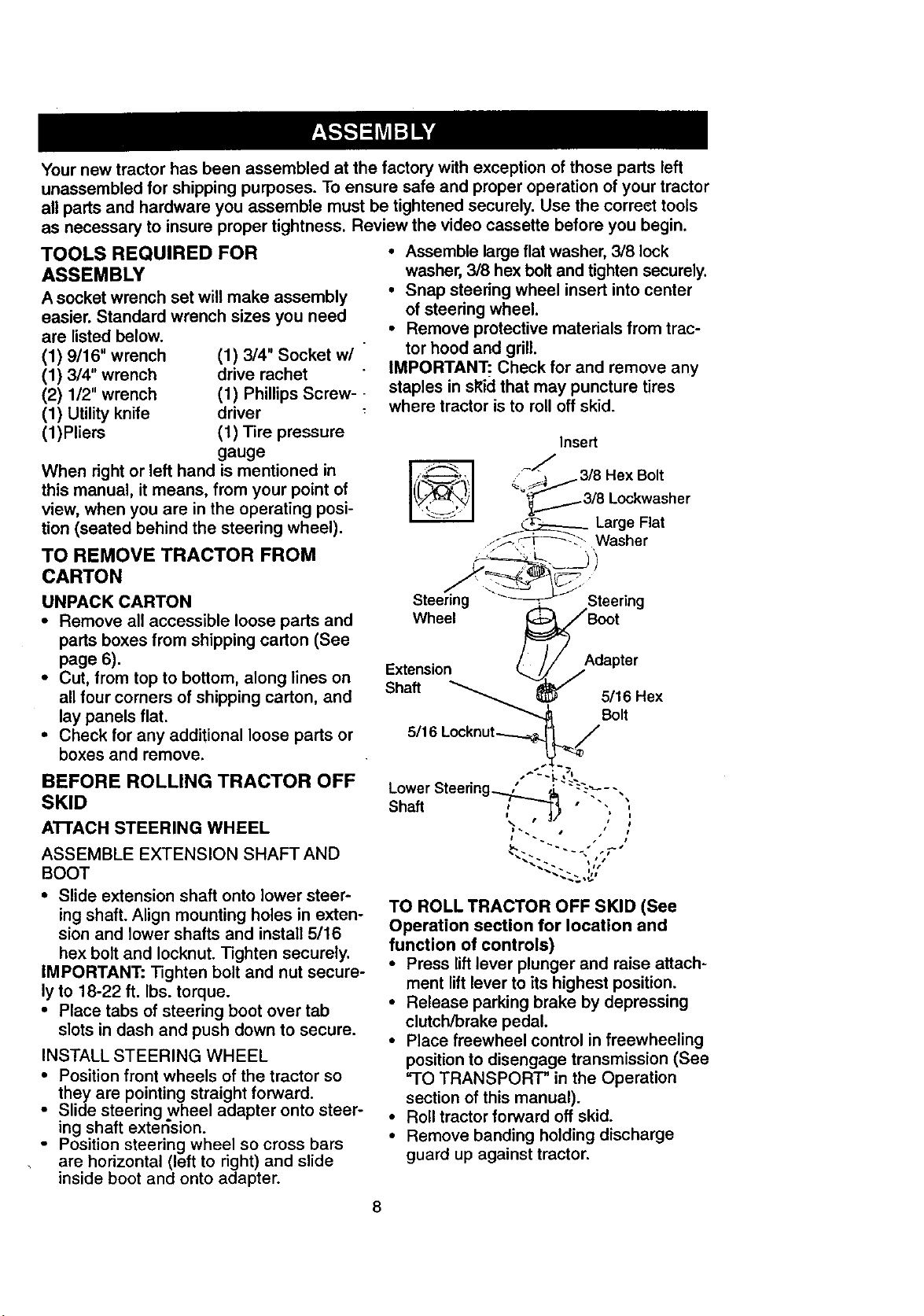
ATrACH STEERING WHEEL
ASSEMBLE EXTENSION SHAFT AND
BOOT
• Slide extension shaft onto lower steer-
ing shaft. Align mounting holes in exten-
sion and lower shafts and install 5/16
hex bolt and Iocknut. Tighten securely.
iMPORTANT: Tighten bolt and nut secure-
ly to 18-22 ft. Ibs. torque.
• Place tabs of steering boot over tab
slots in dash and push down to secure.
INSTALL STEERING WHEEL
• Position front wheels of the tractor so
they are pointing straight forward.
• Slide steering wheel adapter onto steer-
ing shaft extension.
- Position steering wheel so cross bars
are horizontal (left to right) and slide
inside boot and onto adapter.
• Assemble large flat washer 3/8 lock
washer, 3/8 hex bolt and tighten securely.
• Snap steering wheel insert into center
of steering wheel.
• Remove protective materials from trac-
tor hood and grill.
IMPORTANT: Check for and remove any
staples in sl<id that may puncture tires
where tractor is to roll off skid.
TO ROLL TRACTOR OFF SKID (See
Operation section for location and
function of controls)
• Press lift lever plunger and raise attach-
ment lift lever to its highest position.
• Release parking brake by depressing
clutch/brake pedal.
• Place freewheel control in freewheeling
position to disengage transmission (See
=TO TRANSPORT" in the Operation
section of this manual).
• Roll tractor forward off skid.
• Remove banding holding discharge
guard up against tractor.
8
HOW TO SET UP YOUR TRACTOR
CHECK BATTERY
• Lift hood to raised position.
• If this battery is put into service after
month and year indicated on label (label
located between terminals) charge bat-
tery for minimum of one hour at 6-10
amps. (See "BATTERY" in MAINTE-
NANCE section of this manual for
charging instructions).
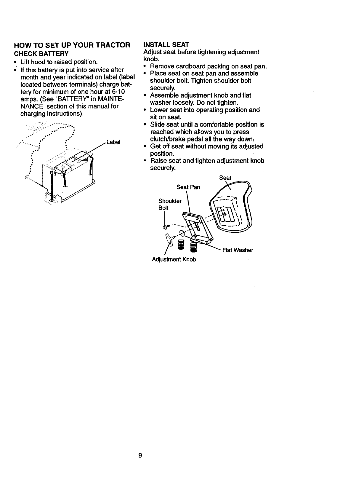
INSTALL SEAT
Adjust seat before tightening adjustment
knob.
• Remove cardboard packing on seat pan.
• Place seat on seat pan and assemble
shoulder bolt. Tighten shoulder bolt
securely.
• Assemble adjustment knob and flat
washer loosely. Do not tighten.
• Lower seat into operating position and
sit on seat.
• Slide seat until a comfortable position is
reached which allows you to press
clutch/brake pedal all the way down;
• Get off seat without moving its adjusted
position.
• Raise seat and tighten adjustment knob
securely.
Seat
Seat Pan
Shoulder
Bolt
Adjustment Knob
Rat Washer
9
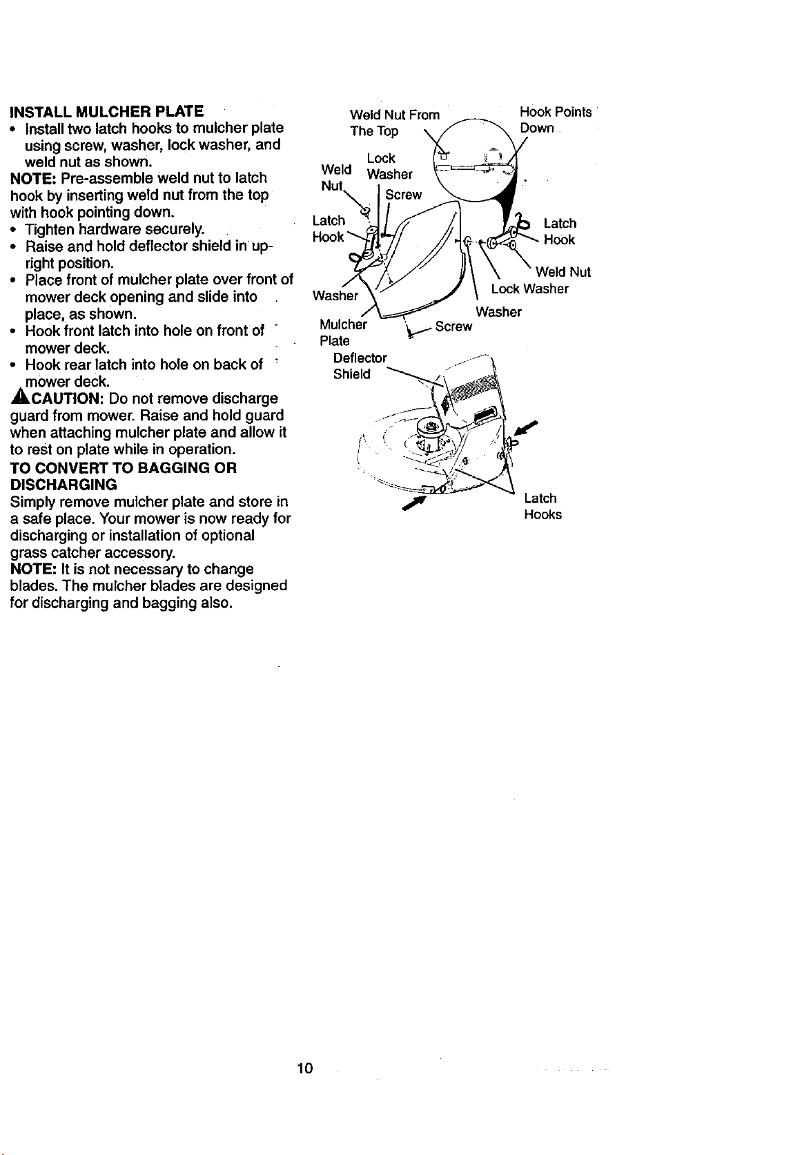
INSTALL MULCHER PLATE
• Install two latch hooks to mulcher plate
using screw, washer, lock washer, and
weld nut as shown.
NOTE: Pre-assemb! e weld nut to latch
hook by inserting weld nut from the top
with hook pointing down.
• Tighten hardware securely.
• Raise and hold deflector shield in up-
right position.
• Place front of mulcher plate over front of
mower deck opening and slide into
place, as shown.
• Hook front latch into hole on front of "
mower deck.
• Hook rear latch into hole on back of
mower deck.
,A, CAUTION: Do not remove discharge
guard from mower. Raise and hold guard
when attaching mulcher plate and allow it
to rest on plate while in operation.
TO CONVERT TO BAGGING OR
DISCHARGING
Simply remove mulcher plate and store in
a safe place. Your mower is now ready for
discharging or installation of optional
grass catcher accessory.
NOTE: It is not necessary to change
blades. The mulcher blades are designed
for discharging and bagging also.
Weld Nut From
The Top
Lock
Weld Washer
Hook Points
Down
Latch
Latch
Hook
Washer
Hooks
10
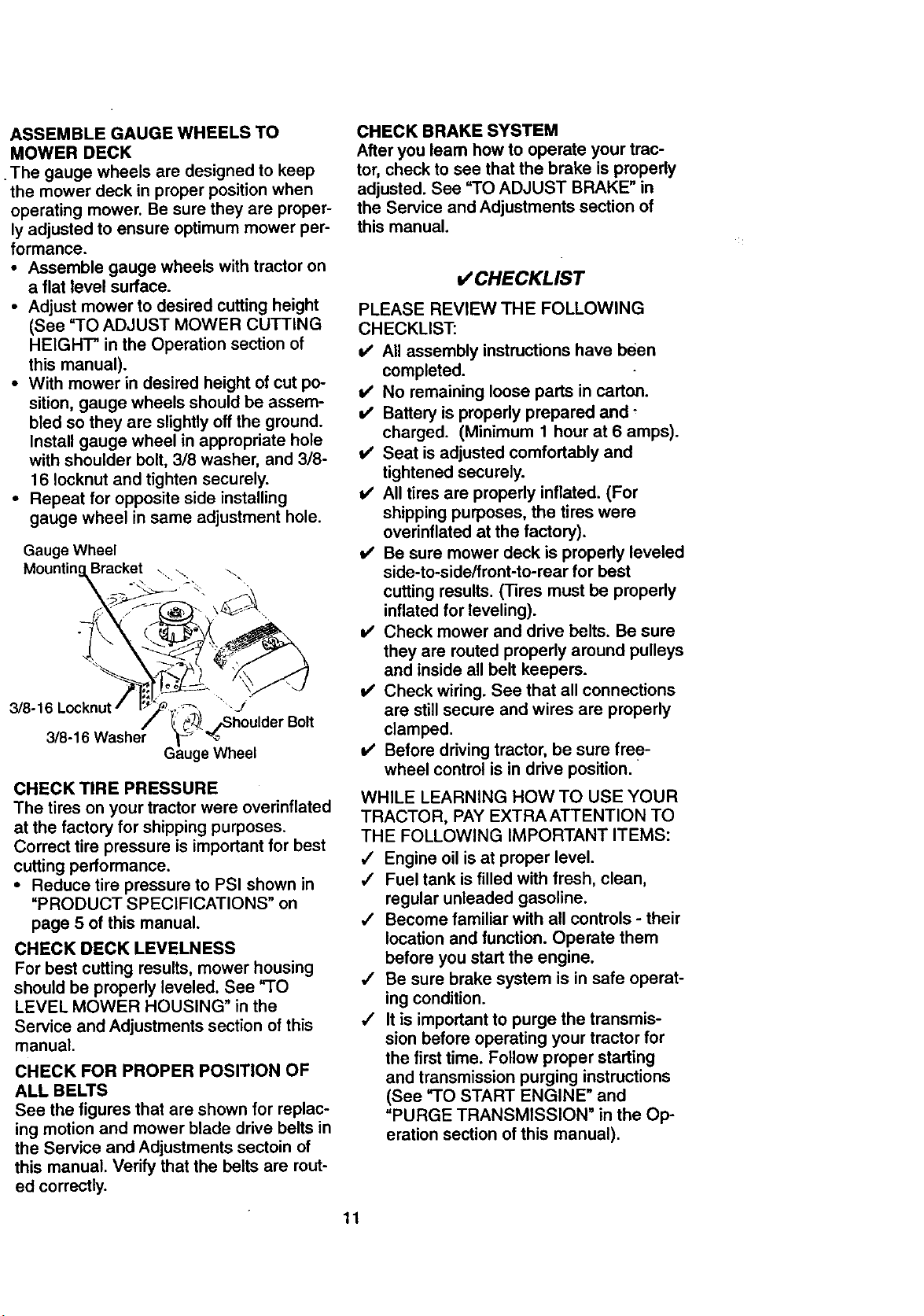
ASSEMBLE GAUGE WHEELS TO
MOWER DECK
The gauge wheels are designed to keep
the mower deck in proper position when
operating mower. Be sure they are proper-
ly adjusted to ensure optimum mower per-
formance.
• Assemble gauge wheels with tractor on
a flat level surface.
• Adjust mower to desired cutting height
(See =TO ADJUST MOWER CUTTING
HEIGH-I" in the Operation section of
this manual).
• With mower in desired height of cut po-
sition, gauge wheels should be assem-
bled so they are slightly off the ground.
Install gauge wheel in appropriate hole
with shoulder bolt, 3/8 washer, and 3/8-
16 Iocknut and tighten securely.
• Repeat for opposite side installing
gauge wheel in same adjustment hole.
Gauge Wheel
Mountin Bracket ...._ \
3/8-16Washer
_rBolt
Wheel
CHECK TIRE PRESSURE
The tires on your tractor were overinflated
at the factory for shipping purposes.
Correct tire pressure is important for best
cutting performance.
• Reduce tire pressure to PSI shown in
"PRODUCT SPECIFICATIONS" on
page 5 of this manual.
CHECK DECK LEVELNESS
For best cutting results, mower housing
should be properly leveled. See =TO
LEVEL MOWER HOUSING" in the
Service and Adjustments section of this
manual.
CHECK FOR PROPER POSITION OF
ALL BELTS
See the figures that are shown for replac-
ing motion and mower blade drive belts in
the Service and Adjustments sectoin of
this manual. Verify that the belts are rout-
ed correctly.
CHECK BRAKE SYSTEM
After you leam how to operate your trac-
tor, check to see that the brake is properly
adjusted. See "TO ADJUST BRAKE" in
the Service and Adjustments section of
this manual.
,/CHECKLIST
PLEASE REVIEW THE FOLLOWING
CHECKLIST:
v' All assembly instructions have been
completed.
v' No remaining loose parts in carton.
v' Battery is properly prepared and _
charged. (Minimum 1 hour at 6 amps).
I/ Seat is adjusted comfortably and
tightened securely.
v' All tires are properly inflated. (For
shipping purposes, the tires were
overinflated at the factory).
v' Be sure mower deck is propedy leveled
side-to-side/front-to-rear for best
cutting results. (Tires must be properly
inflated for leveling).
i/ Check mower and drive belts. Be sure
they are routed propedy around pulleys
and inside all belt keepers.
_' Check wiring. See that all connections
are still secure and wires are properly
clamped.
i/ Before driving tractor, be sure free-
wheel control is in drive position.
WHILE LEARNING HOW TO USE YOUR
TRACTOR, PAY EXTRA ATTENTION TO
THE FOLLOWING IMPORTANT ITEMS:
,/ Engine oil is at proper level.
J Fuel tank is filled with fresh, clean,
regular unleaded gasoline.
,/ Become familiar with all controls - their
location and function. Operate them
before you start the engine.
,I Be sure brake system is in safe operat-
ing condition.
,/ It is important to purge the transmis-
sion before operating your tractor for
the first time. Follow proper starting
and transmission purging instructions
(See =TO START ENGINE" and
"PURGE TRANSMISSION" in the Op-
eration section of this manual).
11
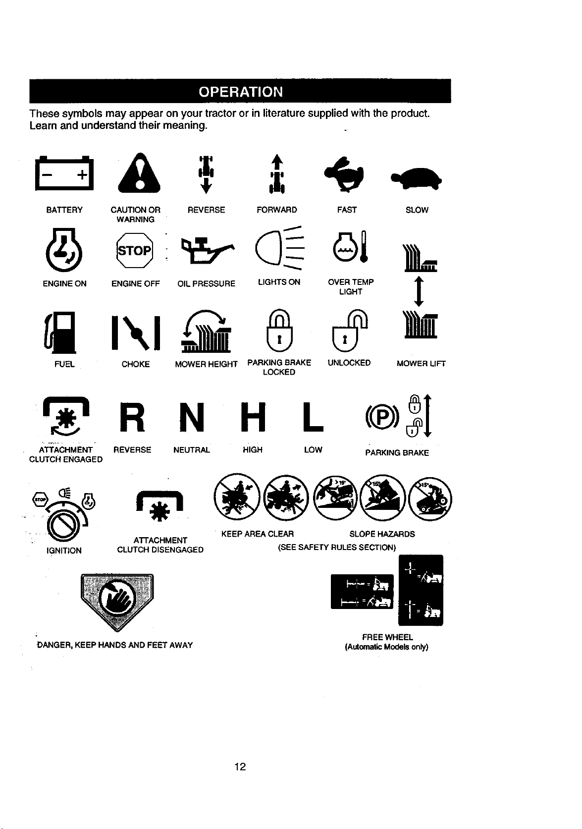
These symbols may appear on your tractor or in literature supplied with the product.
Learn and understand their meaning.
BATTERY CAUTION OR REVERSE FORWARD FAST SLOW
WARNING
ENGINE ON ENGINE OFF OIL PRESSURE
FUEL CHOKE
LIGHTS ON OVER TEMP
,I,
LIGHT
MOWER HEIGHT PARKING BRAKE UNLOCKED MOWER LIFT
LOCKED
R N H
-_-'-- -ATTACHMENT" REVERSE NEUTRAL HIGH
CLUTCH ENGAGED
L (®>3[
LOW PARKING BRAKE
- KEEP AREA CLEAR SLOPE HAZARDS
ATTACHMENT
IGNITION CLUTCH DISENGAGED (SEE SAFETY RULES SECTION)
_ii,i _i_i¸
DANGER, KEEP HANDS AND FEET AWAY
FREE WHEEL
(Automatic Models only)
12
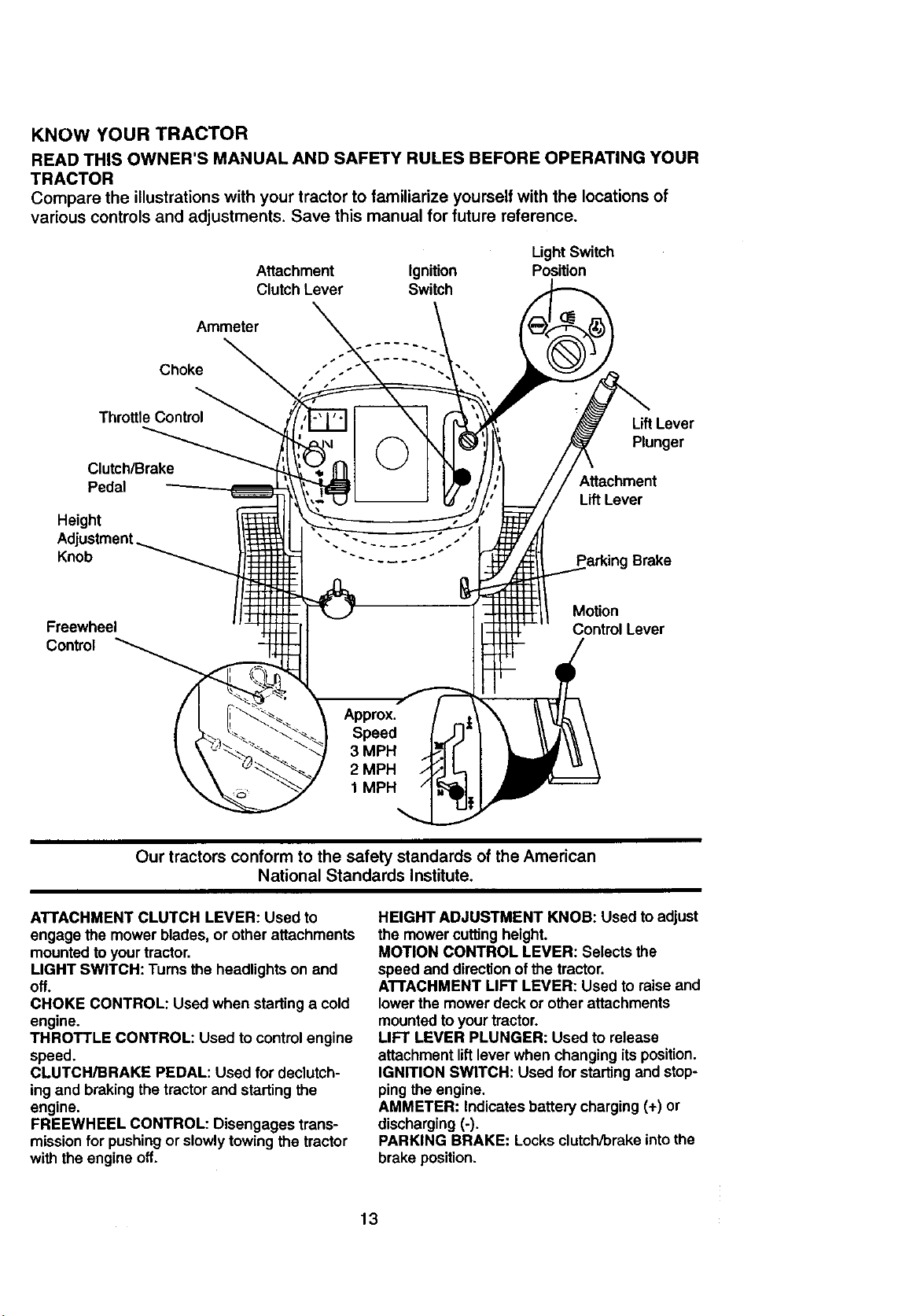
KNOW YOUR TRACTOR
READ THIS OWNER'S MANUAL AND SAFETY RULES BEFORE OPERATING YOUR
TRACTOR
Compare the illustrations with your tractor to familiarize yourself with the locations of
various controls and adjustments. Save this manual for future reference.
Attachment Ignition
Clutch Lever Switch
Light Switch
Position
Ammeter
Choke
ThrottleControl
Clutch/Brake
Pedal
Height
Knob
LiftLever
Plunger
Attachment
LiftLever
Parking Brake
Freewheel
Control
Motion
Control Lever
Our tractors conform to the safety standards of the American
National Standards Institute.
ATTACHMENT CLUTCH LEVER: Used to
engage the mower blades, or other attachments
mounted to yourtractor.
LIGHT SWITCH: Tums the headlights on and
off.
CHOKE CONTROL: Used when starting a cold
engine.
THROTTLE CONTROL: Used to controlengine
speed.
CLUTCH/BRAKE PEDAL: Used for declutch-
ingand brakingthe tractorand starting the
engine.
FREEWHEEL CONTROL: Disengages trans-
missionfor pushingor slowlytowing the tractor
with the engine off.
HEIGHT ADJUSTMENT KNOB: Used to adjust
the mower cuffingheight.
MOTION CONTROL LEVER: Selects the
speed and directionof the tractor.
ATTACHMENT LIFT LEVER: Used to raise and
lower the mower deck or other attachments
mounted to yourtractor.
LIFT LEVER PLUNGER: Used to release
attachment liftlever when changing itsposition.
IGNITION SWITCH: Used for startingand stop-
ping the engine.
AMMETER: Indicates battery charging (+) or
discharging (-).
PARKING BRAKE: Locks clutch/brake intothe
brake position.
13
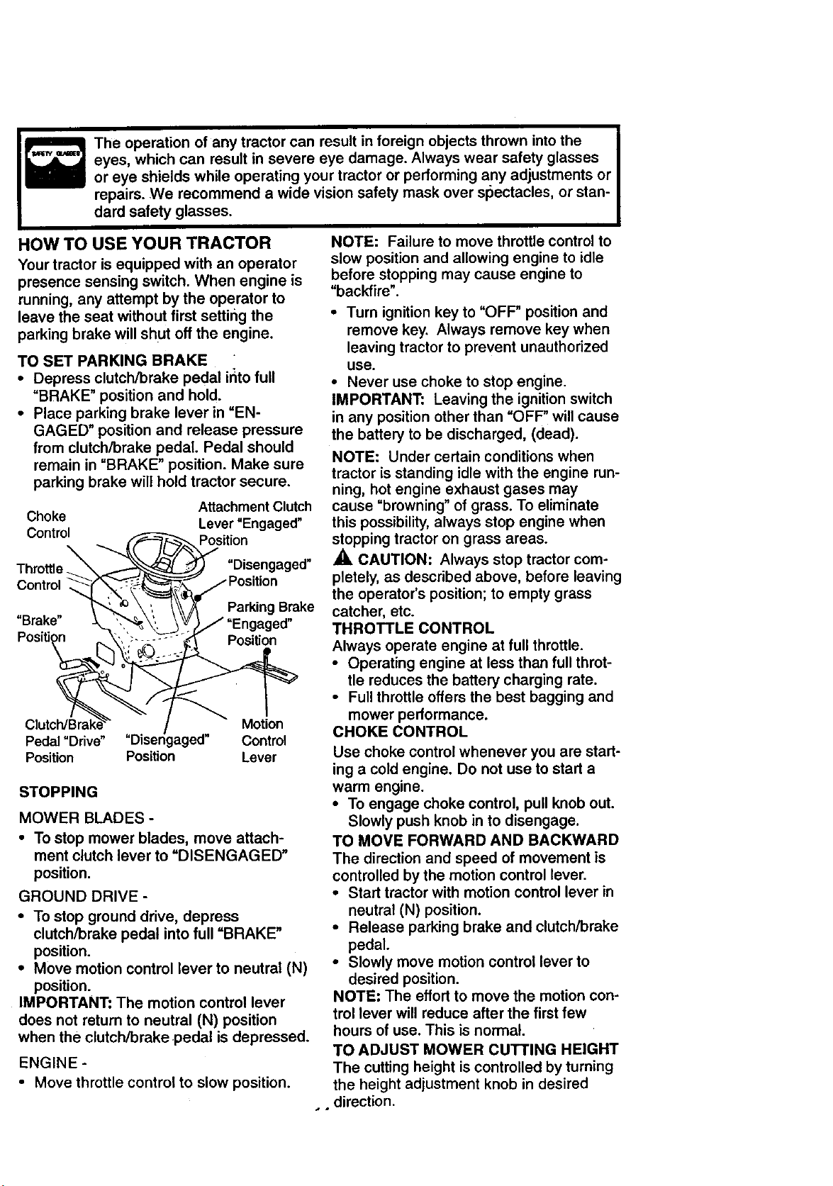
Theoperationofanytractorcan result in foreign objects thrown into the
eyes, which can result in severe eye damage. Always wear safety glasses
or eye shields while operating your tractor or performing any adjustments or
repairs. We recommend a wide vision safety mask over slSectacles, or stan-
dard safety glasses.
HOW TO USE YOUR TRACTOR
Your tractor is equipped with an operator
presence sensing switch. When engine is
running, any attempt by the operator to
leave the seat without first setting the
parking brake will shut off the engine.
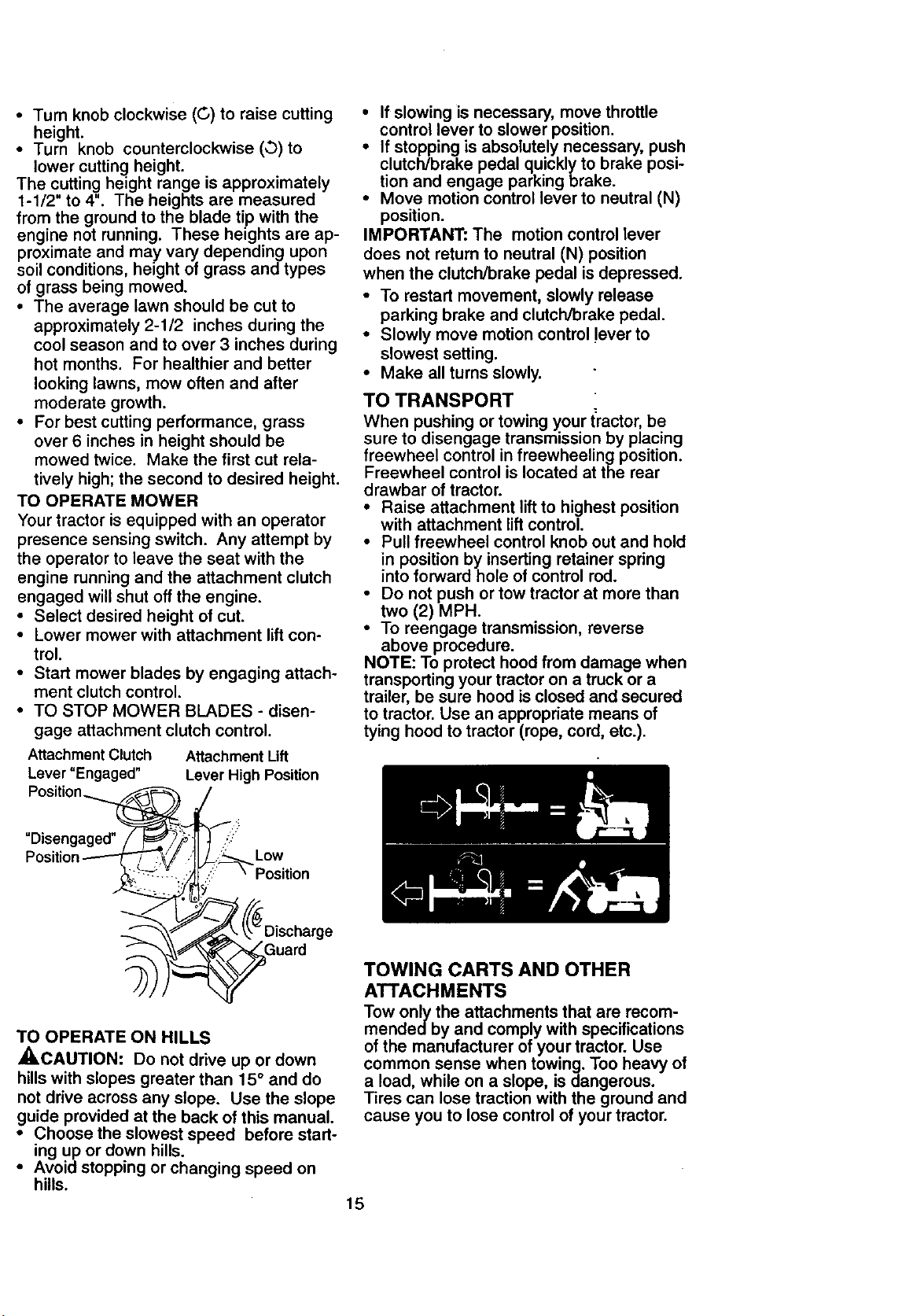
TO SET PARKING BRAKE
• Depress clutch/brake pedal ir_tofull
=BRAKE" position and hold.
• Place parking brake lever in "EN-
GAGED" position and release pressure
from clutch/brake pedal. Pedal should
remain in =BRAKE" position. Make sure
parking brake will hold tractor secure.
Attachment Clutch
Choke Lever "Engaged"
Control
Position
"Disengaged"
Control
Parking Brake
"Brake"
Position
Motion
Pedal "Drive" "Disengaged" Control
Position Position Lever
STOPPING
MOWER BLADES -
• To stop mower blades, move attach-
ment clutch lever to "DISENGAGED"
position.
GROUND DRIVE-
• To stop ground drive, depress
clutch/brake pedal into full =BRAKE"
position.
• Move motion control lever to neutral (N)
position.
IMPORTANT: The motion control lever
does not return to neutral (N) position
when the clutch/brake pedal is depressed.
ENGINE -
• Move throttle control to slow position.
NOTE: Failure to move throttle control to
slow position and allowing engine to idle
before stopping may cause engine to
=backfire".
• Turn ignition key to "OFF" position and
remove key. Always remove key when
leaving tractor to prevent unauthorized
use.
• Never use choke to stop engine.
IMPORTANT: Leaving the ignition switch
in any position other than "OFF" will cause
the battery to be discharged, (dead).
NOTE: Under certain conditions when
tractor is standing idle with the engine run-
ning, hot engine exhaust gases may
cause =browning" of grass. To eliminate
this possibility, always stop engine when
stopping tractor on grass areas.
_, CAUTION: Always stop tractor com-
pletely, as described above, before leaving
the operator's position; to empty grass
catcher, etc.
THROTTLE CONTROL
Always operate engine at full throttle.
• Operating engine at less than full throt-
tle reduces the battery charging rate.
• Full throttle offers the best bagging and
mower performance.
CHOKE CONTROL
Use choke control whenever you are start-
ing a cold engine. Do not use to start a
warm engine.
• To engage choke control, pull knob out.
Slowly push knob in to disengage.
TO MOVE FORWARD AND BACKWARD
The direction and speed of movement is
controlled by the motion control lever.
• Start tractor with motion control lever in
neutral (N) position.
• Release parking brake and clutch/brake
pedal.
• Slowly move motion control lever to
desired position.
NOTE: The effort to move the motion con-
trol lever will reduce after the first few
hours of use. This is normal.
TO ADJUST MOWER CUTTING HEIGHT
The cutting height is controlled by turning
the height adjustment knob in desired
direction.
• Turn knob clockwise (C,) to raise cutting
height.
• Turn knob counterclockwise (_) to
lower cutting height.
The cutting height range is approximately
1-1/2" to 4". The heights are measured
from the ground to the blade tip with the
engine not running. These heights are ap-
proximate and may vary depending upon
soil conditions, height of grass and types
of grass being mowed.
• The average lawn should be cut to
approximately 2-1/2 inches during the
cool season and to over 3 inches during
hot months. For healthier and better
looking lawns, mow often and after
moderate growth.
• For best cutting performance, grass
over 6 inches in height should be
mowed twice. Make the first cut rela-
tively high; the second to desired height.
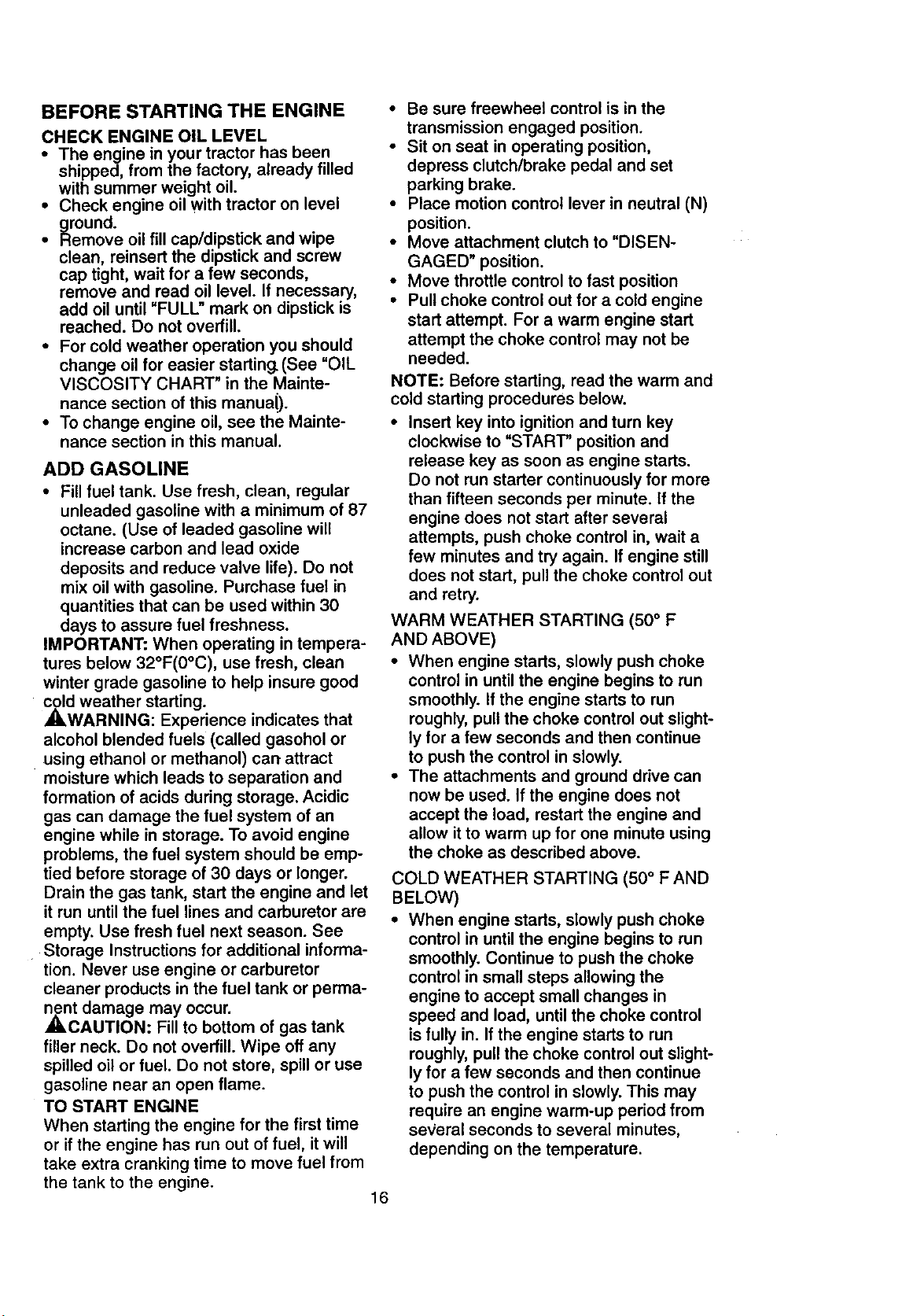
TO OPERATE MOWER
Your tractor is equipped with an operator
presence sensing switch. Any attempt by
the operator to leave the seat with the
engine running and the attachment clutch
engaged will shut off the engine.
• Select desired height of cut.
• Lower mower with attachment lift con-
trol.
• Start mower blades by engaging attach-
ment clutch control.
• TO STOP MOWER BLADES - disen-
gage attachment clutch control.
Attachment Clutch
Lever "Engaged"
Attachment Lift
Lever High Position
• If slowing is necessary, move throttle
control lever to slower position.
• If stopping is absolutely necessary, push
clutch/brake pedal quickly to brake posi-
tion and engage parking brake.
• Move motion control lever to neutral (N)
position.
IMPORTANT: The motion control lever
does not return to neutral (N) position
when the clutch/brake pedal is depressed.
• To restart movement, slowly release
parking brake and clutch/brake pedal.
• Slowly move motion control !ever to
slowest setting.
• Make all turns slowly.
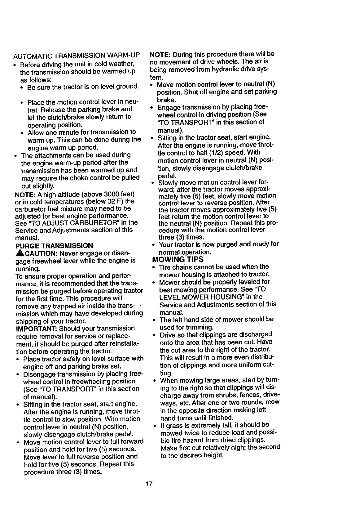
TO TRANSPORT
When pushing or towing your tractor, be
sure to disengage transmission by placing
freewheel control in freewheeling position.
Freewheel control is located at the rear
drawbar of tractor.
• Raise attachment lift to highest position
with attachment lift control.
• Pull freewheel control knob out and hold
in position by inserting retainer spring
into forward hole of control red.
• Do not push or tow tractor at more than
two (2) MPH.
• To reengage transmission, reverse
above procedure.
NOTE: To protect hood from damage when
transporting your tractor on a truck or a
trailer, be sure hood is closed and secured
to tractor. Use an appropriate means of
tying hood to tractor (rope, cord, etc.).
"Disengaged"
Low
Guard
TO OPERATE ON HILLS
_CAUTION: Do not drive up or down
hills with slopes greater than 15 ° and do
not drive across any slope. Use the slope
guide provided at the back of this manual.
• Choose the slowest speed before start-
ing up or down hills.
• Avoid stopping or changing speed on
hills.
TOWING CARTS AND OTHER
ATTACHMENTS
Tow only the attachments that are recom-
mendedby and comply with specifications
of the manufacturer of your tractor. Use
common sense when towing. Too heavy of
a load, while on a slope, is dangerous.
Tires can lose traction with the ground and
cause you to lose control of your tractor.
15
BEFORE STARTING THE ENGINE
CHECK ENGINE OIL LEVEL
• The engine in your tractor has been
shipped, from the factory, already filled
with summer weight oil.
• Check engine oil with tractor on level
ground.
• Remove oil fill cap/dipstick and wipe
clean, reinsert the dipstick and screw
cap tight, wait for a few seconds,
remove and read oil level. If necessary,
add oil until "FULL" mark on dipstick is
reached. Do not overfill.
• For cold weather operation you should
change oil for easier starting. (See "OIL
VISCOSITY CHART" in the Mainte-
nance section of this manua().
• To change engine oil, see the Mainte-
nance section in this manual.
ADD GASOLINE
• Fill fuel tank. Use fresh, clean, regular
unleaded gasoline with a minimum of 87
octane. (Use of leaded gasoline will
increase carbon and lead oxide
deposits and reduce valve life). Do not
mix oil with gasoline. Purchase fuel in
quantities that can be used within 30
days to assure fuel freshness.
IMPORTANT: When operating in tempera-
tures below 32°F(0°C), use fresh, clean
winter grade gasoline to help insure good
cold weather starting.
JILWARNING: Experience indicates that
alcohol blended fuels (called gasohol or
using ethanol or methanol) can attract
moisture which leads to separation and
formation of acids during storage. Acidic
gas can damage the fuel system of an
engine while in storage. To avoid engine
problems, the fuel system should be emp-
tied before storage of 30 days or longer.
Drain the gas tank, start the engine and let
it run until the fuel lines and carburetor are
empty. Use fresh fuel next season. See
Storage Instructions for additional informa-
tion. Never use engine or carburetor
cleaner products in the fuel tank or perma-
nent damage may occur.
_,CAUTION: Fill to bottom of gas tank
filler neck. Do not overfill. Wipe off any
spilled oil or fuel. Do not store, spill or use
gasoline near an open flame.
TO START ENGINE
When starting the engine for the first time
or if the engine has run out of fuel, it will
take extra cranking time to move fuel from
the tank to the engine.
16
• Be sure freewheel control is in the
transmission engaged position.
• Sit on seat in operating position,
depress clutch/brake pedal and set
parking brake.
• Place motion control lever in neutral (N)
position.
• Move attachment clutch to "DISEN-
GAGED" position.
• Move throttle control to fast position
• Pull choke control out for a cold engine
start attempt. For a warm engine start
attempt the choke control may not be
needed.
NOTE: Before starting, read the warm and
cold starting procedures below.
• Insert key into ignition and turn key
clockwise to "START" position and
release key as soon as engine starts.
Do not run starter continuously for more
than fifteen seconds per minute, if the
engine does not start after several
attempts, push choke control in, wait a
few minutes and try again. If engine still
does not start, pull the choke control out
and retry.
WARM WEATHER STARTING (50 ° F
AND ABOVE)
• When engine starts, slowly push choke
control in until the engine begins to run
smoothly. If the engine starts to run
roughly, pull the choke control out slight-
ly for a few seconds and then continue
to push the control in slowly.
• The attachments and ground drive can
now be used. If the engine does not
accept the load, restart the engine and
allow it to warm up for one minute using
the choke as described above.
COLD WEATHER STARTING (50 ° F AND
BELOW)
• When engine starts, slowly push choke
control in until the engine begins to run
smoothly. Continue to push the choke
control in small steps allowing the
engine to accept small changes in
speed and load, until the choke control
is fully in. If the engine starts to run
roughly, pull the choke control out slight-
ly for a few seconds and then continue
to push the control in slowly. This may
require an engine warm-up period from
several seconds to several minutes,
depending on the temperature.
AUTOMATIC I RANSMISSION WARM-UP
• Before driving the unit in cold weather,
the transmission should be warmed up
as follows:
• Be sure the tractor is on level ground.
• Place the motion control lever in neu-
tral. Release the parking brake and
let the clutch/brake slowly retum to
operating position.
• Allow one minute for transmission to
warm up. This can be done during the
engine warm up period.
• The attachments can be used during
the engine warm-up period after the
transmission has been warmed up and
may require the choke control be pulled
out slightly.
NOTE: A high altitude (above 3000 feet)
or in cold temperatures (below 32 F) the
carburetor fuel mixture may need to be
adjusted for best engine performance.
See "TO ADJUST CARBURETOR" in the
Service and Adjustments section of this
manual.
PURGE TRANSMISSION
A, CAUTION: Never engage or disen-
gage freewheel lever while the engine is
running,
To ensure proper operation and perfor-
mance, it is recommended that the trans-
mission be purged before operating tractor
for the first time. This procedure will
remove any trapped air inside the trans-
mission which may have developed during
shipping of your tractor.
IMPORTANT: Should your transmission
require removal for service or replace-
ment, it should be purged after reinstalla-
tion before operating the tractor.
• Place tractor safely on level surface with
engine off and parking brake set.
• Disengage transmission by placing free-
wheel control in freewheeling position
(See "TO TRANSPORT" in this section
of manual).
• Sitting in the tractor seat, start engine.
After the engine is running, move throt-
tle control to slow position. With motion
control lever in neutral (N) position,
slowly disengage clutch/brake pedal.
• Move motion control lever to full forward
position and hold for five (5) seconds.
Move lever to full reverse position and
hold for five (5) seconds. Repeat this
procedure three (3) times.
NOTE: During this procedure there will be
no movement of drive wheels. The air is
being removed from hydraulic drive sys-
tem.
• Move motion control lever to neutral (N)
position. Shut oft engine and set parking
brake.
• Engage transmission by placing free-
wheel control in driving position (See
"TO TRANSPORT" in this section of
manual).
• Sitting in the tractor seat, start engine.
After the engine is running,move throt-
tle control to half (1/2) speed. With
motion control lever in neutral (N) posi-
tion, slowly disengage clutch/brake
pedal.
• Slowly move motion control lever for-
ward; after the tractor moves approxi-
mately five (5) feet, slowly move motion
control lever to reverse position. After
the tractor moves approximately five (5)
feet return the motion control lever to
the neutral (N) position. Repeat this pro-
cedure with the motion control lever
three (3) times.
• Your tractor is now purged and ready for
normal operation.
MOWING TIPS
• Tire chains cannot be used when the
mower housing is attached to tractor.
• Mower should be properly leveled for
best mowing performance. See "TO
LEVEL MOWER HOUSING" in the
Service and Adjustments section of this
manual.
• The left hand side of mower should be
used for trimming.
• Drive so that clippings are discharged
onto the area that has been cut. Have
the cut area to the right of the tractor.
This will result in a more even distribu-
tion of clippings and more uniform cut-
ting.
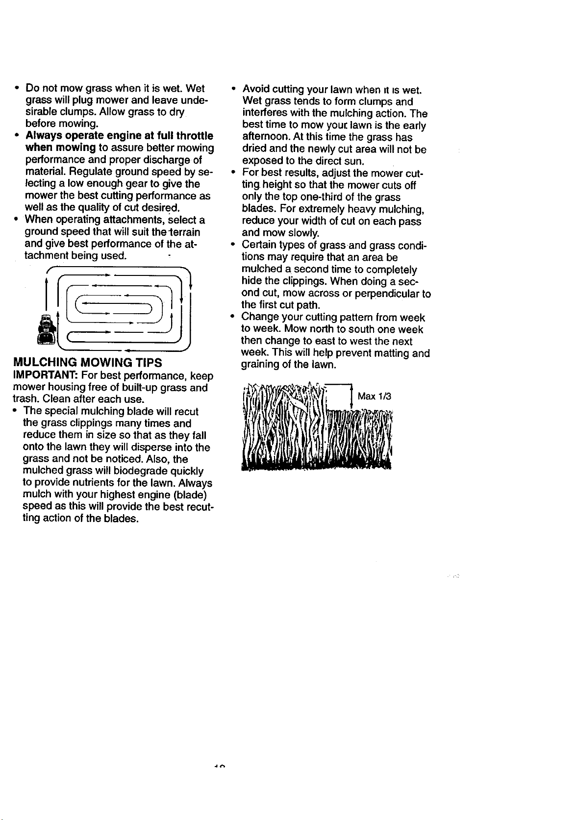
• When mowing large areas, start by turn-
ing to the right so that clippings will dis-
charge away from shrubs, fences, drive-
ways, etc. After one or two rounds, mow
in the opposite direction making left
hand turns until finished.
• If grass is extremely tall, it should be
mowed twice to reduce load and possi-
ble fire hazard from dried clippings.
Make first cut relatively high; the second
to the desired height.
17
• Do not mow grass when it is wet. Wet
grass will plug mower and leave unde-
sirable clumps. Allow grass to dry
before mowing.
• Always operate engine at full throttle
when mowing to assure better mowing
performance and proper discharge of
material. Regulate ground speed by se-
lecting a low enough gear to give the
mower the best cutting performance as
well as the quality of cut desired.
• When operating attachments, Select a
ground speed that will suit thelerrain
and give best performance of the at-
tachment being used.
f
t J
MULCHING MOWING TIPS
IMPORTANT: For best performance, keep
mower housing free of built-up grass and
trash. Clean after each use.
• The special mulching blade will recut
the grass clippings many times and
reduce them in size so that as they fall
onto the lawn they will disperse into the
grass and not be noticed. Also, the
mulched grass will biodegrade quickly
to provide nutrients for the lawn. Always
mulch with your highest engine (blade)
speed as this will provide the best recut-
ting action of the blades.
• Avoid cutting your lawn when it is wet.
Wet grass tends to form clumps and
interferes with the mulching action. The
best time to mow you[ lawn is the early
afternoon. At this time the grass has
dried and the newly cut area will not be
exposed to the direct sun.
• For best results, adjust the mower cut-
ting height so that the mower cuts off
only the top one-third of the grass
blades. For extremely heavy mulching,
reduce your width of cut on each pass
and mow slowly.
• Certain types of grass and grass condi-
tions may require that an area be
mulched a second time to completely
hide the clippings. When doing a sec-
ond cut, mow across or perpendicular to
the first cut path.
• Change your cutting pattem from week
to week. Mow north to south one week
then change to east to west the next
week. This will help prevent matting and
graining of the lawn.
M+",,+
I . ii i t ,.
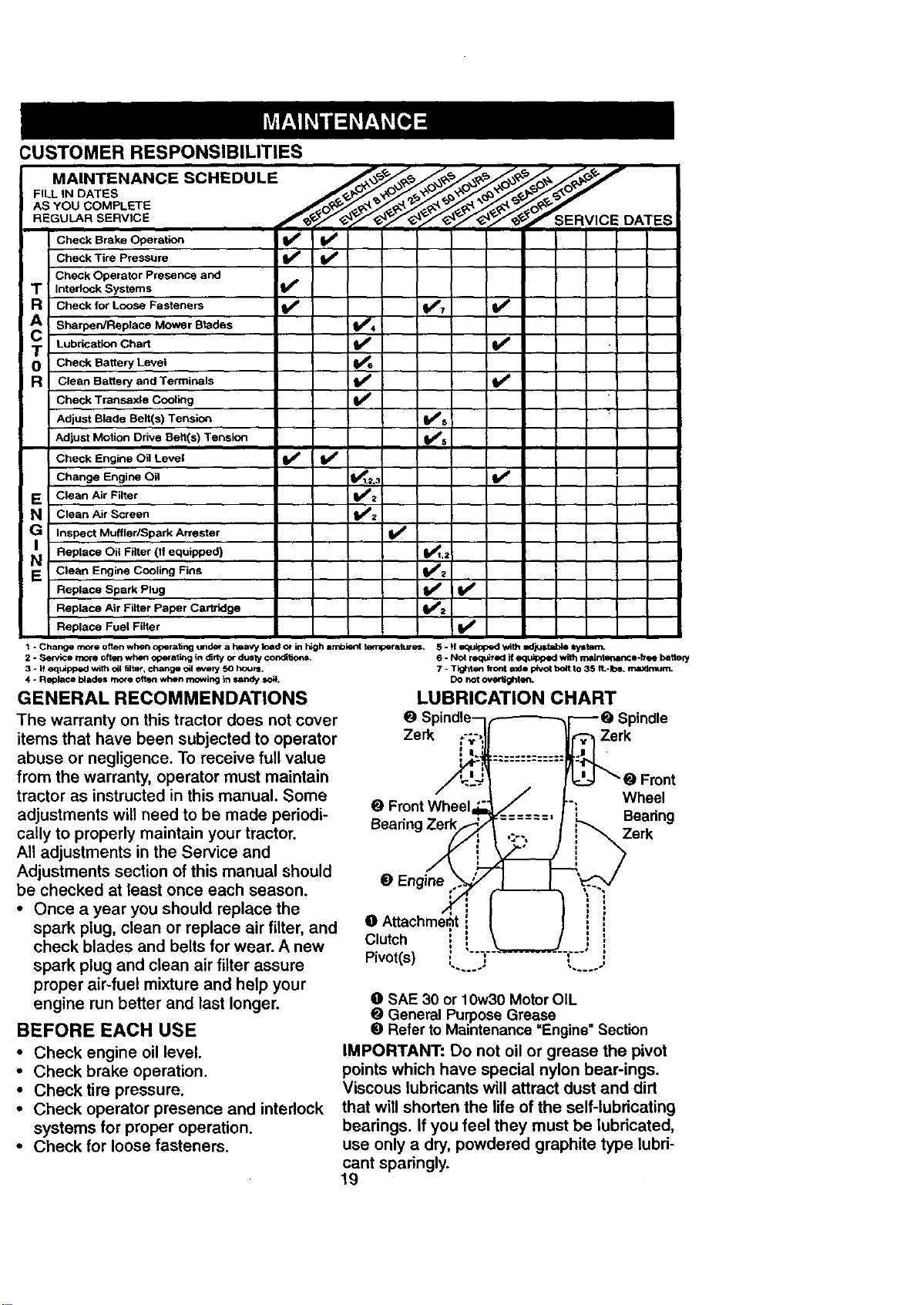
CUSTOMER RESPONSIBILITIES
MAINTENANCE SCHEDULE __ ,___ _ _o_. ,_ /'_
FILL,.DATES
ASYOUCOMPLET
CheokBrake erot=
i Check Tire Pgessure
I Check Operator Presence and
Intedcck Systems IS"
Check for Loose Fasteners _ V'7 V'
: Sharpen/Replace Mower Blades V'4
Lubrication Chart _ V _
O Check Battery Level
Clean Battery and Terminals
Check Transaxla Cooling Ik_
Adjust Blade Belt(s) Tension V's
Adjust Motion Drive Belt(s) Tension
v',
= Check Engine Oil Level _ II_
Change Engine Oil I1_1.=,: If
E Clean Air Filter
i N Clean Air Screen
: G Inspect Muffler/Spark Arrester V'
= Replace Oil Filter (If equipped) I_1,2
i EN ClaanEngineC°°lingFins _'
Replace Spark Plug I_
: Replace Air Filter Paper Cartridge I_=
Replace Fuel Filter V'
1 - Change more often when operating urtde_ a heavy toad or in high ambient terrlperatur_, 5 - _|_lpp<KI _lh IKFJ_ltab_l ir/ltam.
2 - Service more ofttm when ope_atktg in dirty or d_ty condft_oP_.
3 - If equipped with oil filter, change oil _Nely 50 hours,
4 * Replace blades more often when m_wing in sandy =o_.
GENERAL RECOMMENDATIONS
The warranty on this tractor does not cover
items that have been subjected to operator
abuse or negligence. To receive full value
from the warranty, operator must maintain
tractor as instructed in this manual. Some
adjustments will need to be made periodi-
cally to properly maintain your tractor.
All adjustments in the Service and
Adjustments section of this manual should
be checked at least once each season.
• Once a year you should replace the
spark plug, clean or replace air filter, and
check blades and belts for wear. A new
spark plug and clean air filter assure
proper air-fuel mixture and help your
engine run better and last longer.
BEFORE EACH USE
• Check engine oil level.
• Check brake operation.
• Checktire pressure.
• Check operator presence and interlock
systems for proper operation.
• Check for loose fasteners.
6 - Nol requ_ed if equipped with mairderlr tce-h'9<J heftefy
7 * TIg_lterl h'ont axJe pfvo_ bolt to 35 fL-Ib_, rm_lmum.
DO not ove_ghten.
LUBRICATION CHART
O
Zerk Zerk
O FrontWheel Wheel
Beadng
Beadng Zerk
O Engine
O
Clutch i
Pivot(s) _....j
t l
O SAE 30 or 10w30 Motor OIL
O General Purpose Grease
O Refer to Maintenance =Engine" Section
IMPORTANT: Do not oil or grease the pivot
points which have special nylon bear-ings.
Viscous lubricants will attract dust and dirt
that will shorten the life of the self-lubricating
bearings. If you feel they must be lubricated,
use only a dry, powdered graphite type lubri-
cant sparingly.
19
TRACTOR
Always observe safety rules when per-
forming any maintenance.
BRAKE OPERATION
If tractor requires more than six (6) feet
stopping distance at high speed in highest
gear, then brake must be adjusted. (See
"TO ADJUST BRAKE" in the Service and
Adjustments section of this manual).
TIRES
• Maintain proper air pressure in all tires
(See "PRODUCT SPECIFICATIONS"
on page 3 of this manual).
• Keep tires free of gasolir_e, oil, or insect
control chemicals which can harm rub-
her.
• Avoid stumps, stones, deep ruts, sharp
objects and other hazards that may
cause tire damage.
NOTE: To seal tire punctures and prevent
flat tires due to slow leaks, tire sealant
may be purchased from your local parts
dealer. Tire sealant also prevents tire dry
rot and corrosion.
OPERATOR PRESENCE SYSTEM
Be sure that operator presence and inter-
lock systems are working properly. If your
tractor does not function as described
below, repair the problem immediately.
• The engine should not start unless the
clutch/brake pedal is fully depressed
and attachment clutch control is in the
disengaged position.
• When the engine is running, any
attempt by the operator to leave the
seat without first setting the parking
brake should shut off the engine.
• When the engine is running and the
attachment clutch is engaged, any
attempt by the operator to leave the
seat should shut off the engine.
• The attachment clutch should never
operate unless the operator is in the
seat.
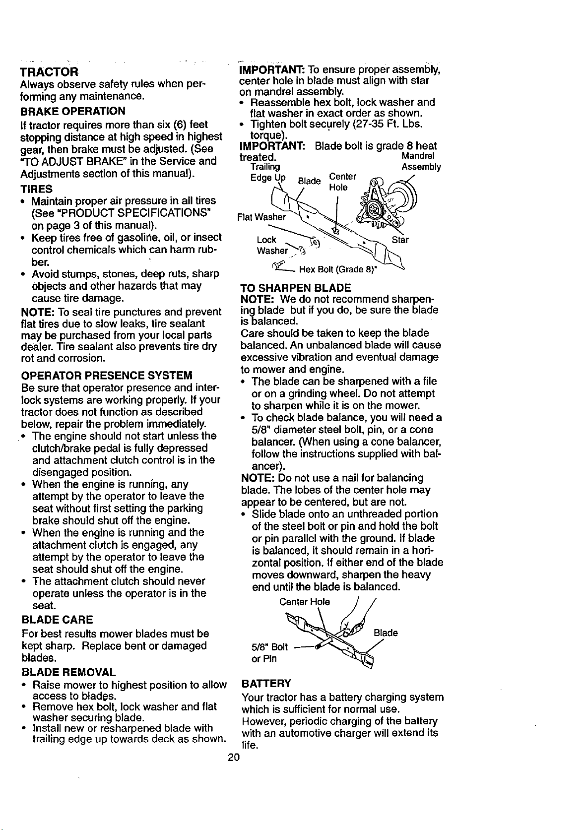
IMPORTANT: To ensure proper assembly,
center hole in blade must align with star
on mandrel assembly.
• Reassemble hex bolt, lock washer and
flat washer in exact order as shown.
• Tighten bolt securely (27-35 Ft. Lbs.
torque).
IMPORTANT: Blade bolt is grade 8 heat
treated. Mandrel
Trailing Assembly
Edge Blade Center
Hole
Flat Washer
Lock Star
_-- Hex Bolt (Grade 8)"
TO SHARPEN BLADE
NOTE: We do not recommend sharpen-
ing blade but if you do, be sure the blade
is balanced.
Care should be taken to keep the blade
balanced. An unbalanced blade will cause
excessive vibration and eventual damage
to mower and engine.
• The blade can be sharpened with a file
or on a grinding wheel. Do not attempt
to sharpen while it is on the mower.
• To check blade balance, you will need a
5/8" diameter steel bolt, pin, or a cone
balancer. (When using a cone balancer,
follow the instructions supplied with bal-
ancer).
NOTE: Do not use a nail for balancing
blade. The lobes of the center hole may
appear to be centered, but are not.
• Slide blade onto an unthreaded portion
of the steel bolt or pin and hold the bolt
or pin parallel with the ground. If blade
is balanced, it should remain in a hori-
zontal position. If either end of the blade
moves downward, sharpen the heavy
end until the blade is balanced.
Center Hole
BLADE CARE
For best results mower blades must be
kept sharp. Replace bent or damaged
blades.
5/8" Bolt
or Pin
Blade
BLADE REMOVAL
• Raise mower to highest position to allow
access to blades.
• Remove hex bolt, lock washer and flat
washer securing blade.
• Install new or resharpened blade with
trailing edge up towards deck as shown.
BATTERY
Your tractor has a battery charging system
which is sufficient for normal use.
However, periodic charging of the battery
with an automotive charger will extend its
life.
2O
• Keep battery and terminals clean.
• Keep battery bolts tight.
• Keep small vent holes open.
• Recharge at 6-10 amperes for 1 hour.
TO CLEAN BATTERY AND TERMINALS
Corrosion and dirt on the battery and ter-
minals can cause the battery to "leak"
power.
• Remove terminal guard.
• Disconnect BLACK battery cable first
then RED battery cable and remove
battery from tractor.
• Rinse the battery with plain water and
dry.
• Clean terminals and battery cable ends
with wire brush until bright.
• Coat terminals with grease or petroleum
jelly.
• Reinstall battery (See "REPLACING
BATTERY" in the SERVICE AND
ADJUSTMENTS section of this manu-
al).
V-BELTS
Check V-belts for deterioration and wear
after 100 hours of operation and replace if
necessary. The belts are not adjustable.
Replace belts if they begin to slip from
wear.
TRANSAXLE COOLING
The transmission fan and cooling fins
should be kept clean to assure proper
cooling.
Do not attempt to clean fan or transmis-
sion while engine is running or while the
transmission is hot.
• Inspect cooling fan to be sure fan
blades are intact and clean.
• Inspect cooling fins for dirt, grass clip-
pings and other materials. To prevent
damage to seals, do not use com-
pressed air or high pressure sprayer to
clean cooling fins.
TRANSAXLE PUMP FLUID
SAE VISCOSITY GRADES
.30* ._o_ .io* o- _o= 20" 30-
TEMPERATURE RANGE ANTICIPATED BEFORE NEXT OIL CHANGE
The transaxle was sealed at the factory
and fluid maintenance is not required for
the life of the transaxle. Should the
transaxle ever leak or require servicing,
contact your nearest authorized service
center.
ENGINE
LUBRICATION
Only use high quality detergent oil rated
with API service classification SF, SG or
SH. Select the oil's SAE viscosity grade
according to your expected operating tem-
perature.
NOTE: Although multi-viscosity oils
(5W30, 10W30 etc.) improve starting in
cold weather, these multi-viscosity oils will
result in increased oil consumption when
used above 32°1=. Check your engine oil
level more frequently toavoid possible
engine damage from running low on oil.
Change the oil after every 25 hours of
operation or at least once a year if the
tractor is not used for 25 hours in one
year.
Check the crankcase oil level before start-
ing the engine and after each eight (8)
hours of operation. Tighten oil fill cap/dip-
stick securely each time you check the oil
level.
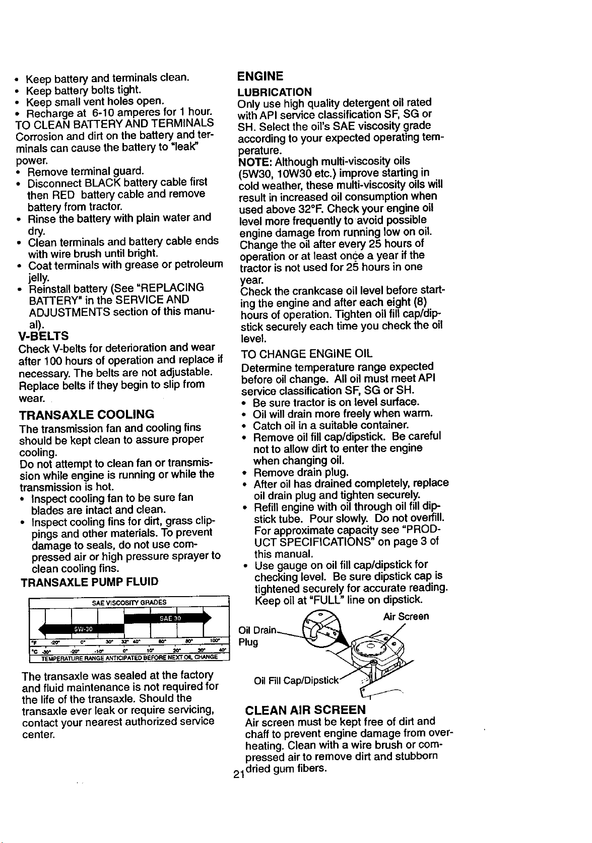
TO CHANGE ENGINE OIL
Determine temperature range expected
before oil change. All oil must meet API
service classification SF, SG or SH.
• Be sure tractor is on level surface.
• Oil will drain more freely when warm.
• Catch oil in a suitable container.
• Remove oil fill cap/dipstick. Be careful
not to allow dirt to enter the engine
when changing oil.
• Remove drain plug.
• After oil has drained completely, replace
oil drain plug and tighten securely.
• Refill engine with oil through oil fill dip-
stick tube. Pour slowly. Do not overfill.
For approximate capacity see "PROD-
UCT SPECIFICATIONS" on page 3 of
this manual.
• Use gauge on oil fill cap/dipstick for
checking level. Be sure dipstick cap is
tightened securely for accurate reading.
Keep oil at "FULL" line on dipstick.
Air Screen
Oil Drain._-_ ___
Plug
o Fi_lCap/Dipstick" _
CLEAN AIR SCREEN
Air screen must be kept free of dirt and
chaff to prevent engine damage from over-
heating. Clean with a wire brush or com-
pressed air to remove dirt and stubborn
21 dried gum fibers.
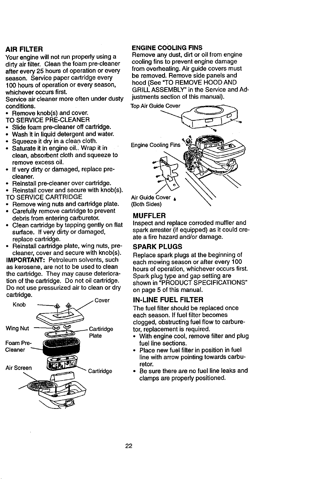
AIR FILTER
Your engine will not run properly using a
dirty air filter. Clean the foam pre-cleaner
after every 25 hours of operation or every
season. Service paper cartridge every
100 hours of operation or every season,
whichever occurs first.
Service air cleaner more often under dusty
conditions.
• Remove knob(s) and cover.
TO SERVICE PRE-CLEANER
• Slide foam pre-cleaner off cartridge.
• Wash it in liquid detergent and water.
• Squeeze it dry in a clean cloth.
• Saturate it in engine oil._ Wrap it in
clean, absorbent cloth and squeeze to
remove excess oil.
• If very dirty or damaged, replace pre-
cleaner.
• Reinstall pre-cleaner over cartridge.
• Reinstall cover and secure with knob(s).
TO SERVICE CARTRIDGE
• Remove wing nuts and cartridge plate.
• Carefully remove cartridge to prevent
debris from entering carburetor.
• Clean cartridge by tapping gently on flat
surface. If very dirty or damaged,
replace cartridge.
• Reinstall cartridge plate, wing nuts, pre-
cleaner, cover and secure with knob(s).
IMPORTANT: Petroleum solvents, such
as kerosene, are not to be used to clean
the cartridge. They may cause deteriora-
tion of the cartridge. Do not oil cartridge.
Do not use pressurized air to clean or dry
cartridge.
Knob
Wing Nut
Foam Pre-
Cleaner
Plate
ge
Air Screen
ENGINE COOLING FINS
Remove any dust, dirt or oil from engine
cooling fins to prevent engine damage
from overheating. Air guide covers must
be removed. Remove side panels and
hood (See "TO REMOVE HOOD AND
GRILL ASSEMBLY" in the Service and Ad,
justments section of this manual).
Top Air Guide_,,,
Air Guide Cover ,,
(Both Sides)
MUFFLER
Inspect and replace corroded muffler and
spark arrester (if equipped) as it could cre-
ate a fire hazard and/or damage.
SPARK PLUGS
Replace spark plugs at the beginning of
each mowing season or after every 100
hours of operation, whichever occurs first.
Spark plug type and gap setting are
shown in "PRODUCT SPECIFICATIONS"
on page 5 of this manual.
IN-LINE FUEL FILTER
The fuel filter should be replaced once
each season. If fuel filter becomes
clogged, obstructing fuel flow to carbure-
tor, replacement is required.
• With engine cool, remove filter and plug
fuel line sections.
• Place new fuel filter in position in fuel
line with arrow pointing towards carbu-
retor.
• Be sure there are no fuel line leaks and
clamps are properly positioned.
22
Filter
CLEANING
• Clean engine, battery, seat, finish, etc.
of all foreign matter.
• Keep finished surfaces and wheels free
of all gasoline, oil, etc.
• Protect painted surfaces with automo-
tive type wax.
We do not recommend using a garden
hose to clean your tractor unless the elec-
trical system, muffler, air filter and carbure-
tor are covered to keep water out. Water
in engine can result in a shortened engine
life.
,_CAUTION: Before performing any service or adjustments:
• Depress clutch/brake pedal fully and set parking brake.
• Place motion control lever in neutral (N) position.
• Place attachment clutch in "DISENGAGED" position.
• Turn ignition key "OFF" and remove key.
• Make sure the blades and all moving parts have completely stopped.
• Disconnect spark plug wire from spark plug and place wire where it cannot come
in contact with plug.
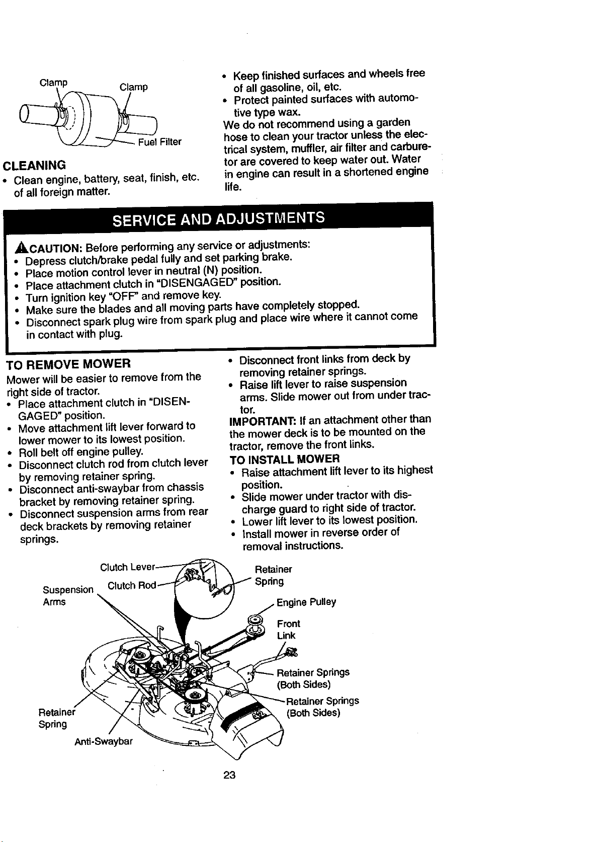
TO REMOVE MOWER
Mower will be easier to remove from the
right side of tractor.
• Place attachment clutch in "DISEN-
GAGED" position.
• Move attachment lift lever forward to
lower mower to its lowest position.
• Roll belt off engine pulley.
• Disconnect clutch rod from clutch lever
by removing retainer spring.
• Disconnect anti-swaybar from chassis
bracket by removing retainer spring.
• Disconnect suspension arms from rear
deck brackets by removing retainer
springs.
Clutch
Suspension
Arms
• Disconnect front links from deck by
removing retainer springs.
• Raise lift lever to raise suspension
arms. Slide mower out from under trac-
tor.
IMPORTANT: If an attachment other than
the mower deck is to be mounted on the
tractor, remove the front links.
TO INSTALL MOWER
• Raise attachment lift lever to its highest
position.
• Slide mower under tractor with dis-
charge guard to right side of tractor.
• Lower lift lever to its lowest position.
• install mower in reverse order of
removal instructions.
Retainer
Spring
Front
Link
Retainer
Spring
Anti-Swaybar
Retainer Springs
Sides)
prings
(Both Sides)
23
TO LEVEL MOWER HOUSING
Adjust the mower while tractor is parked
on level ground or driveway. Make sure
tiros are propedy inflated (See =PROD-
UCT SPECIFICATIONS"). If tires are
over or underinflated, you will not properly
adjust your mower.
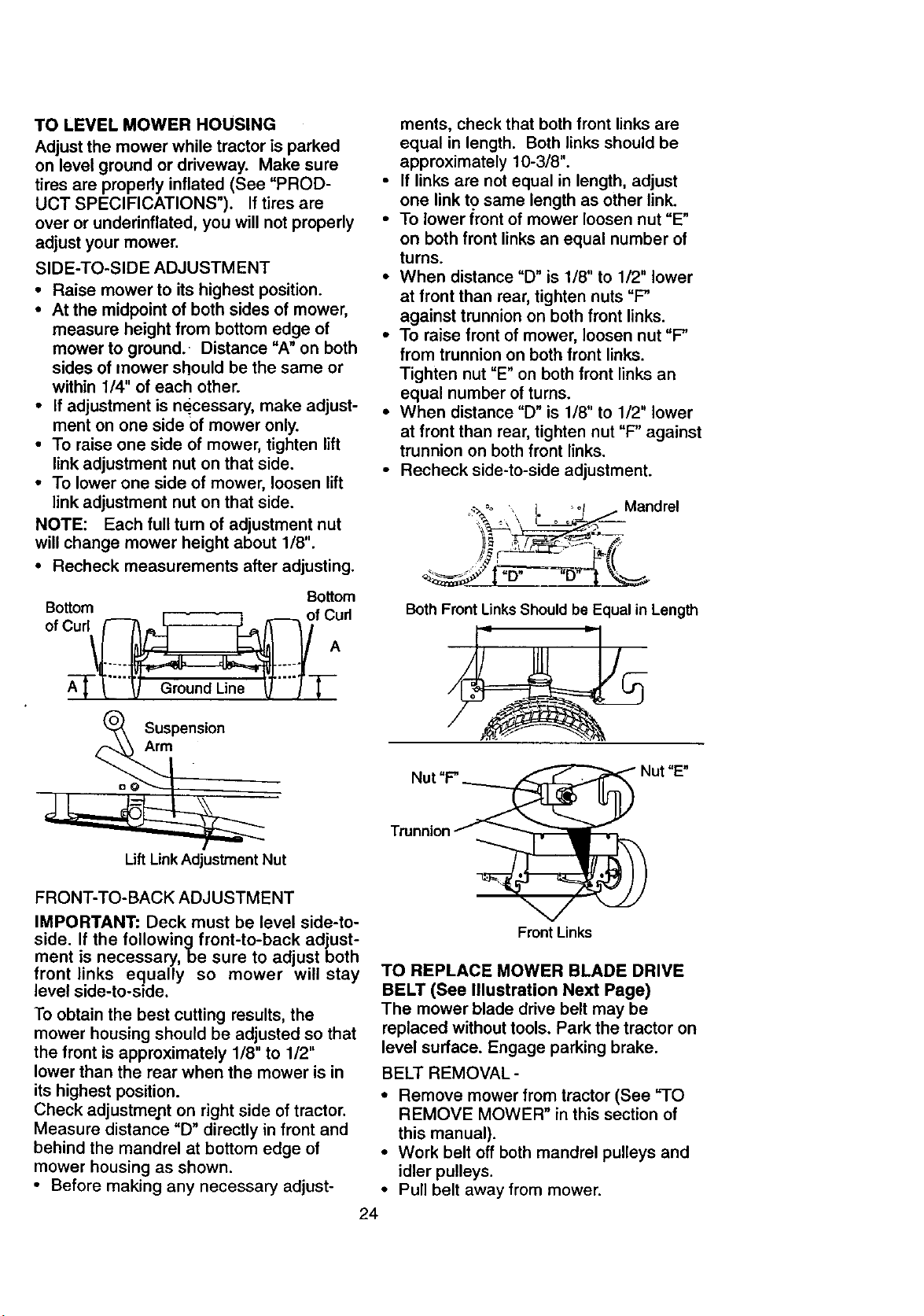
SIDE-TO-SIDE ADJUSTMENT
• Raise mower to its highest position.
• At the midpoint of both sides of mower,
measure height from bottom edge of
mower to ground. Distance "A" on both
sides of mower should be the same or
within 1/4" of each other.
• If adjustment is necessary, make adjust-
ment on one side of mower only.
• To raise one side of mower, tighten lift
link adjustment nut on that side.
• To lower one side of mower, loosen lift
link adjustment nut on that side.
NOTE: Each full turn of adjustment nut
will change mower height about 1/8".
• Recheck measurements after adjusting.
Bottom
Bottom
of Curl/_(_f CAd
Suspension
Arm
ments, check that both front links are
equal in length. Both links should be
approximately 10-3/8".
• If links are not equal in length, adjust
one link to same length as other link.
• To lower front of mower loosen nut "E"
on both front links an equal number of
turns.
• When distance "D" is 1/8" to 1/2" lower
at front than roar, tighten nuts "F"
against trunnion on both front links.
• To raise front of mower, loosen nut =F"
from trunnion on both front links.
Tighten nut "E" on both front links an
equal number of tums.
• When distance "D" is 1/8" to 1/2" lower
at front than rear, tighten nut "F" against
trunnion on both front links.
• Recheck side-to-side adjustment.
_.Oo _o_ Mandrel
/9 r-_',,_.L_ _.
Both Front LinksShouldbe Equal in Length
Lift Link Adjustment Nut
FRONT-TO-BACK ADJUSTMENT
IMPORTANT: Deck must be level side-to-
side. If the followingfront-to-back adjust-
ment is necessary, be sure to adjust both
front links equally so mower will stay
level side-to-side.
To obtain the best cutting results, the
mower housing should be adjusted so that
the front is approximately 1/8" to 1/2"
lower than the rear when the mower is in
its highest position.
Check adjustment on right side of tractor.
Measure distance "D" directly in front and
behind the mandrel at bottom edge of
mower housing as shown.
• Before making any necessary adjust-
Front Links
TO REPLACE MOWER BLADE DRIVE
BELT (See Illustration Next Page)
The mower blade drive belt may be
replaced without tools. Park the tractor on
level surface. Engage parking brake.
BELT REMOVAL-
• Remove mower from tractor (See "TO
REMOVE MOWER" in this section of
this manual).
• Work belt off both mandrel pulleys and
idler pulleys.
• Pull belt away from mower.
24
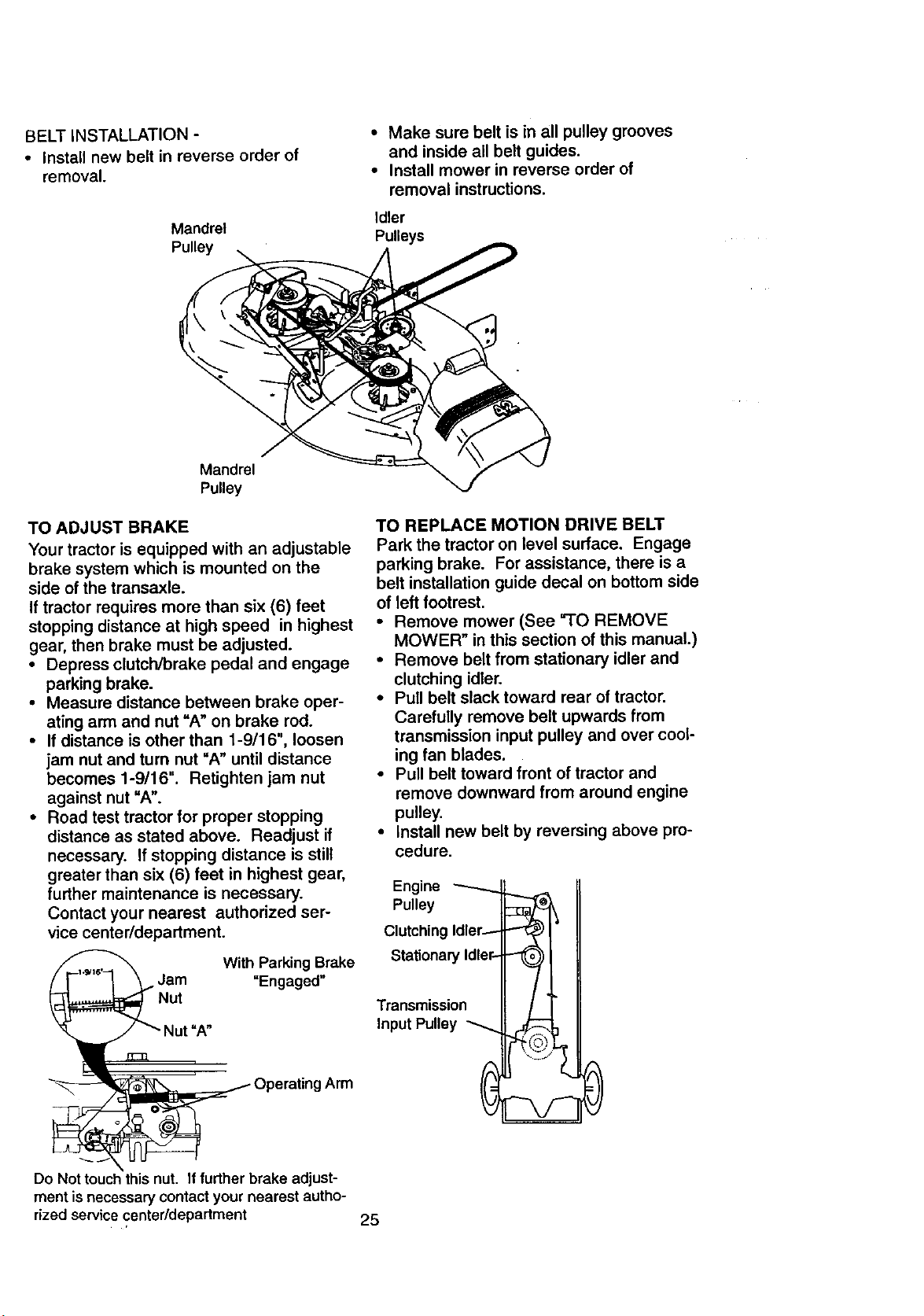
BELT INSTALLATION -
• Install new belt in reverse order of
removal.
Mandrel
Pulley
• Make sure belt is in all pulley grooves
and inside all belt guides.
• Install mower in reverse order of
removal instructions.
Idler
Pulleys
Mandrel
Pulley
TO ADJUST BRAKE
Your tractor is equipped with an adjustable
brake system which is mounted on the
side of the transaxle.
If tractor requires more than six (6) feet
stopping distance at high speed in highest
gear, then brake must be adjusted.
• Depress clutch/brake pedal and engage
parking brake.
• Measure distance between brake oper-
ating arm and nut "A" on brake rod.
• If distance is other than 1-9/16", loosen
jam nut and turn nut "A" until distance
becomes 1-9/16". Retighten jam nut
against nut =A".
• Road test tractor for proper stopping
distance as stated above. Readjust if
necessary. If stopping distance is still
greater than six (6) feet in highest gear,
further maintenance is necessary.
Contact your nearest authorized ser-
vice center/department.
_Jam With Parking Brake
=Engaged"
_Nut
_ Operating Arm
Do Not touch this nut. Iffurther brake adjust-
ment is necessary contact your nearest autho-
rized service center/department
TO REPLACE MOTION DRIVE BELT
Park the tractor on level surface. Engage
parking brake. For assistance, there is a
belt installation guide decal on bottom side
of left footrest.
• Remove mower (See "TO REMOVE
MOWER" in this section of this manual.)
• Remove belt from stationary idler and
clutching idler.
• Pull belt slack toward rear of tractor.
Carefully remove belt upwards from
transmission input pulley and over cool-
ing fan blades.
• Pull belt toward front of tractor and
remove downward from around engine
pulley.
• Install new belt by reversing above pro-
cedure.
Engine
Pulley
Clutching Idler-
Stationary Idler-
Transmission
Input Pulley
25

TO ADJUST MOTION CONTROL LEVER
The motion control lever has been preset
at the factory and adjustment should not
be necessary.
• Loosen adjustment bolt in front of the
right rear wheel, and lightly tighten.
• Start engine and move motion control
lever until tractor does not move forward
or backward.
• Hold motion control lever in that position
and turn engine off.
• While holding motion control lever in
place, loosen the adjustment bo!t_
• Move motion control lever to the'_eutral
(N) (lock gate) position.
• Tighten adjustmeht bolt securely.
NOTE: If additional clearance is needed
to get to adjustment bolt, move mower
deck height to the lowest position.
After above adjustment is made, if the
tractor still creeps forward or backward
while motion control lever is in neutral
position, follow these steps:
• Loosen the adjustment bolt.
• Move the motion control lever 1/4 to 1/2
inch in the direction it is trying to creep.
• Tighten adjustment bolt securely.
• Start engine and test.
• If tractor still creeps, repeat above steps
until satisfied.
Motion Control Lever
Neutral Lock
wheel and reassemble per instruuuu_=sin
the Assembly section of this manual.
FRONT WHEEL TOE-IN/CAMBER
The front wheel toe-in and camber are not
adjustable on your tractor. If damage has
occurred to affect the front wheel toe-in or
camber, contact your nearest authorized
service center.
TO REMOVE WHEEL FOR REPAIRS
• Block up axle securely.
• Remove axle cover, retaining ring and
washers to allow wheel removal (rear
wheel contains a square key - Do not
lose).
• Repair tire and reassemble.
• On rear wheels only: align grooves in
rear wheel hub and axle. Insert square
key.
• Replace washers and snap retaining
ring securely in axle groove.
• Replace axle cover.
NOTE: To seal tire punctures and prevent
flat tires due to slow leaks, tire sealant
may be purchased from your local parts
dealer. Tire sealant also prevents tire dry
rot and corrosion.
Washers
Retaining
Ring
Axle Cover
=_.,_ Square Key
(Rear Wheel Only)
Adjl
TRANSMISSION REMOVAL/REPLACE-
MENT
Should your transmission require remova!
for service or replacement, it should be
purged after reinstailation and before
operating the tractor. See "PURGE
TRANSMISSION" in the Operation section
of this manual.
TO ADJUST STEERING WHEEL ALIGN-
MENT
if steering wheel crossbars are not hori-
zontal (left to right) when wheels are posi-
tioned straight forward, remove steering
TO START ENGINE WITH A WEAK
BATTERY
•,CAUTION" Lead-acid batteries gener-
ate explosive gases. Keep sparks, flame
and smoking materials away from batter-
ies. Always wear eye protection when
around batteries.
if your battery is too weak to start the
engine, it should be recharged. (See
"BATTERY" in the MAINTENANCE sec-
tion of this manual).
If "jumper cables" are used for emergency
starting, follow this procedure:
IMPORTANT: Your tractor Is equipped
with a 12 volt negative grounded system.
The ether vehicle must also be a !2 volt
negative grounded system. Do not use
26 your tractor battery to start other vehicles.
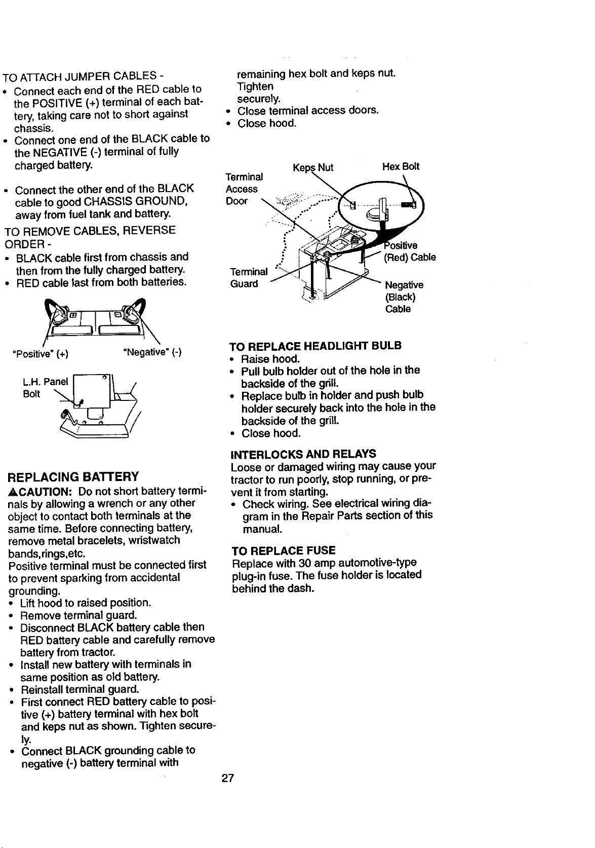
TOATTACHJUMPERCABLES-
• Connect each end of the RED cable to
the POSITIVE (+) terminal of each bat-
tery, taking care not to short against
chassis.
• Connect one end of the BLACK cable to
the NEGATIVE (-) terminal of fully
charged battery.
• Connect the other end of the BLACK
cable to good CHASSIS GROUND,
away from fuel tank and battery.
TO REMOVE CABLES, REVERSE
ORDER -
• BLACK cable first from chassis and
then from the fully charged battery.
• RED cable last from both batteries.
"Positive" (+) "Negative" (-)
L.H. Pan_
Bolt
remaining hex bolt and keps nut.
Tighten
securely.
• Close terminal access doors.
• Close hood.
Terminal
Access
Door
Terminal '"
Guard
Nut Hex Bolt
Cable
(Black)
Cable
TO REPLACE HEADLIGHT BULB
• Raise hood.
• Pull bulb holder out of the hole in the
backside of the grill.
• Replace bulb in holder and push bulb
holder securely back into the hole in the
backside of the grill.
• Close hood.
REPLACING BATTERY
•,CAUTION: Do not short battery termi-
nals by allowing a wrench or any other
object to contact both terminals at the
same time. Before connecting battery,
remove metal bracelets, wristwatch
bands,rings,etc.
Positive terminal must be connected first
to prevent sparking from accidental
grounding.
• Lift hood to raised position.
• Remove terminal guard.
• Disconnect BLACK battery cable then
RED battery cable and carefully remove
battery from tractor.
• Install new battery with terminals in
same position as old battery.
• Reinstall terminal guard.
• First connect RED battery cable to posi-
tive (+) battery terminal with hex bolt
and keps nut as shown. Tighten secure-
ly.
• Connect BLACK grounding cable to
negative (-) battery terminal with
INTERLOCKS AND RELAYS
Loose or damaged wiring may cause your
tractor to run poorly, stop running, or pre-
vent it from starting.
• Check wiring. See electrical wiring dia-
gram in the Repair Parts section of this
manual.
TO REPLACE FUSE
Replace with 30 amp automotive-type
plug-in fuse. The fuse holder is located
behind the dash.
27
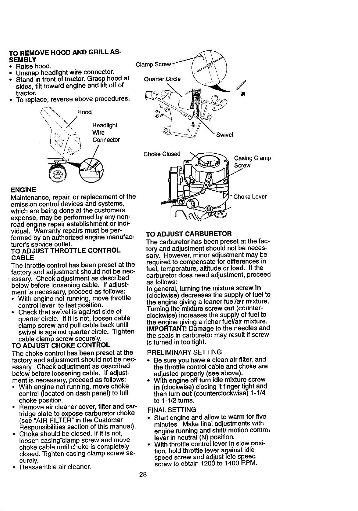
TO REMOVE HOOD AND GRILL AS-
SEMBLY
• Raise hood.
Unsnap headlight wire connector.
Stand =nfront of tractor. Grasp hood at
sides, tilt toward engine and lift off of
tractor.
• To replace, reverse above procedures.
Hood
\
• . Headlight
", ' Wire
Connector
Quarter Circle
Choke Closed
;wivel
Casing Clamp
Screw
ENGINE
Maintenance, repair, or replacement of the
emission control devices and systems,
which are being done at the customers
expense, may be performed by any non-
road engine repair establishment or indi-
vidual. Warranty repairs must be per-
formed by an authorized engine manufac-
turer's service outlet.
TO ADJUST THROTTLE CONTROL
CABLE
The throttle control has been preset at the
factory and adjustment should not be nec-
essary. Check adjustment as described
below before loosening cable. If adjust-
ment is necessary, proceed as follows:
• With engine not running, move throttle
control lever to fast position.
• Check that swivel is against side of
quarter circle. If it is not, loosen cable
clamp screw and pull cable back until
swivel is against quarter circle. Tighten
cable clamp screw securely.
TO ADJUST CHOKE CONTROL
The choke control has been preset at the
factory and adjustment should not be nec-
essary. Check adjustment as described
below before loosening cable. If adjust-
ment is necessary, proceed as follows:
• With engine not running, move choke
control (located on dash panel) to full
choke position.
• Remove air cleaner cover, filter and car-
tridge plate to expose carburetor choke
(see "AIR FILTER" in the Customer
Responsibilities section of this manual).
• Choke should be closed. If it is not,
loosen casing'clamp screw and move
choke cable until choke is completely
closed. Tighten casing clamp screw se-
curely.
• Reassemble air cleaner.
Choke Lever
TO ADJUST CARBURETOR
The carburetor has been preset at the fac-
tory and adjustment should not be neces-
sary. However, minor adjustment may be
required to compensate for differences in
fuel, temperature, altitude or load. If the
carburetor does need adjustment, proceed
as follows:
In general, turning the mixture screw In
(clockwise) decreases the supply of fuel to
the engine giving a leaner fuel/air mixture.
Turning the mixture screw out (counter-
clockwise) increases the supply of fuel to
the engine giving a richer fuel/air mixture.
IMPORTANT: Damage to the needles and
the seats in carburetor may result if screw
is turned in too tight.
PRELIMINARY SETTING
• Be sure you have a clean air fitter, and
the throttle control cable and choke are
adjusted properly (see above).
• With engine off turn id}e mixture screw
in (clockwise) closing it finger tight and
then turn out (counterclockwise) 1-1/4
to 1-1/2 turns.
FINAL SE'I-rlNG
• Start engine and allow to warm for five
minutes. Make final adjustments with
engine running and shift/motion control
lever in neutral (N) position.
• With throttle control lever in slow posi-
tion, hold throttle lever against idle
speed screw and adjust idle speed
screw to obtain 1200 to 1400 RPM.
28
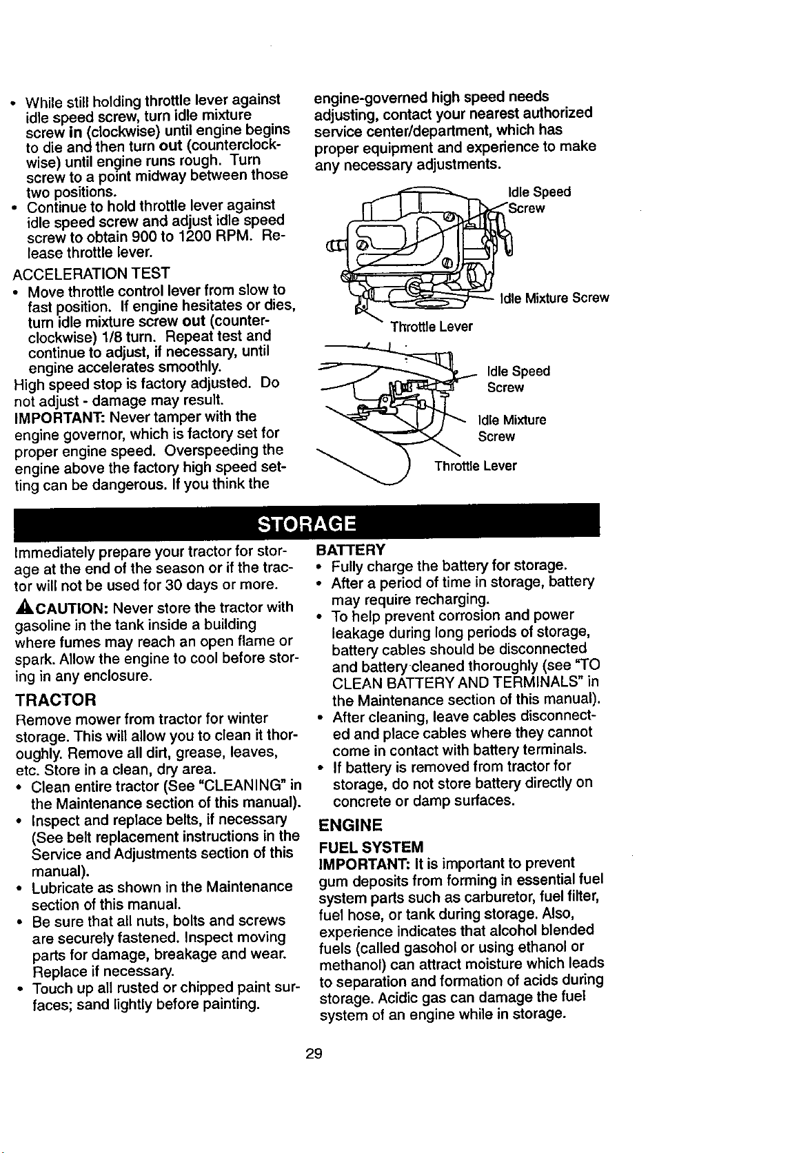
- While still holding throttle lever against
idle speed screw, turn idle mixture
screw in(clockwise) until engine begins
to die and then turn out (counterclock-
wise) until engine runs rough. Turn
screw to a point midway between those
two positions.
• Continue to hold throttle lever against
idle speed screw and adjust idle speed
screw to obtain 900 to 1200 RPM. Re-
lease throttle lever.
ACCELERATION TEST
• Move throttle control lever from slow to
fast position. If engine hesitates or dies,
turn idle mixture screw out (counter-
clockwise) 1/8 turn. Repeat test and
continue to adjust, if necessary, until
engine accelerates smoothly.
High speed stop is factory adjusted. Do
not adjust - damage may result.
IMPORTANT: Never tamper with the
engine governor, which is factory set for
proper engine speed. Overspeeding the
engine above the factory high speed set-
ting can be dangerous. If you think the
engine-governed high speed needs
adjusting, contact your nearest authorized
service center/department, which has
proper equipment and experience to make
any necessary adjustments.
I_le Speed
crew
Idle Mixture Screw
Throttle Lever
Idle Speed
Screw
Idle Mixture
Screw
Throttle Lever
Immediately prepare your tractor for stor-
age at the end of the season or if the trac-
tor will not be used for 30 days or more.
,_ CAUTION: Never store the tractor with
gasoline in the tank inside a building
where fumes may reach an open flame or
spark. Allow the engine to cool before stor-
ing in any enclosure.
TRACTOR
Remove mower from tractor for winter
storage. This will allow you to clean it thor-
oughly. Remove all dirt, grease, leaves,
etc. Store in a clean, dry area.
• Clean entire tractor (See "CLEANING" in
the Maintenance section of this manual).
• Inspect and replace belts, if necessary
(See belt replacement instructions in the
Service and Adjustments section of this
manual).
• Lubricate as shown in the Maintenance
section of this manual.
• Be sure that all nuts, bolts and screws
are securely fastened. Inspect moving
parts for damage, breakage and wear.
Replace if necessary.
• Touch up all rusted or chipped paint sur-
faces; sand lightly before painting.
BATTERY
• Fully charge the battery for storage.
• After a period of time in storage, battery
may require recharging.
• To help prevent corrosion and power
leakage during long periods of storage,
battery cables should be disconnected
and battery cleaned thoroughly (see "TO
CLEAN BATTERY AND TERMINALS" in
the Maintenance section of this manual).
• After cleaning, leave cables disconnect-
ed and place cables where they cannot
come in contact with battery terminals.
• If battery is removed from tractor for
storage, do not store battery directly on
concrete or clamp surfaces.
ENGINE
FUEL SYSTEM
IMPORTANT: It is important to prevent
gum deposits from forming in essential fuel
system parts such as carburetor, fuel filter,
fuel hose, or tank during storage. Also,
experience indicates that alcohol blended
fuels (called gasohol or using ethanol or
methanol) can attract moisture which leads
to separation and formation of acids during
storage. Acidic gas can damage the fuel
system of an engine while in storage.
29
• Drain the fuel tank.
• Start the engine and let it run until the
fuel lines and carburetor are empty.
• Never use engine or carburetor cleaner
products in the fuel tank or permanent
damage may occur.
• Use fresh fuel next season.
NOTE: Fuel stabilizer is an acceptable
alternative in minimizing the formation of
fuel gum deposits during storage. Add sta-
bilizer to gasoline in fuel tank or storage
container. Always follow the mix ratio
found on stabilizer container. Run engine
at least 1@minutes after adding stabilizer
to allow the stabilizer to reach the carbure-
tor. Do not drain the gas tank and carbure-
tor if using fuel stabilizer.
ENGINE OIL
Drain oil (with engine warm) and replace
with clean engine oil. (See "ENGINE" in
the Maintenance section of this manual).
CYLINDER(S)
• Remove spark plug(s).
• Pour one ounce of oil through spark plug
hole(s) into cylinder(s),
• Turn ignition key to "START" position for
a few seconds to distribute oil,
• Replace with new spark plug(s).
OTHER
• Do not store gasoline from one season
to another.
• Replace your gasoline can if it starts to
rust. Rust and/or dirt in your gasoline will
cause problems.
• If possible, store your tractor indoors
and cover it to give protection from dust
and dirt.
• Cover your tractor with a suitable protec-
tive cover that does not retain moisture.
Do not use plastic. Plastic cannot
breathe, which allows condensation to
form and cause your tractor to rust.
IMPORTANT: Never cover tractor while :
engine and exhaust areas are still warm.
30
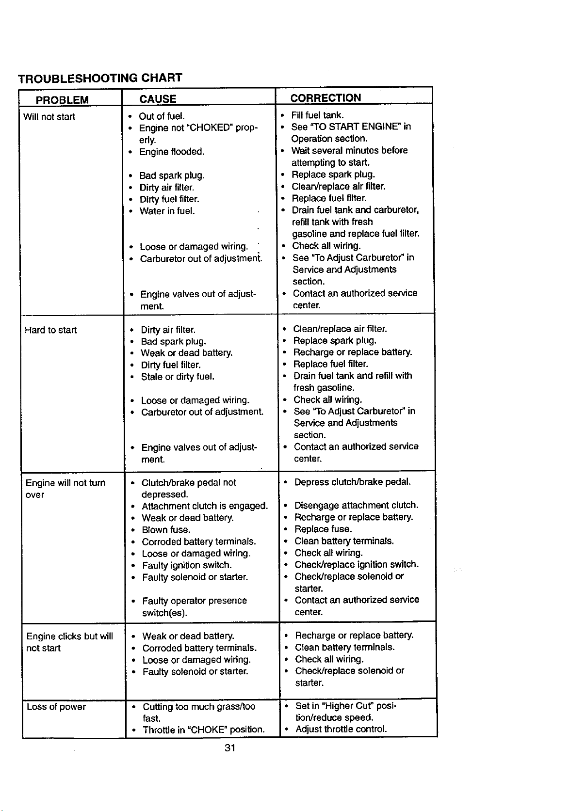
TROUBLESHOOTING CHART
PROBLEM
Will not start
Hard to start
Engine willnot turn
over
Engine clicks but will
not start
Loss of power
CAUSE
• Out of fuel.
• Engine not "CHOKED" prop-
edy.
• Engine flooded.
• Bad spark plug.
• Dirtyair filter.
• Dirty fuel filter.
• Water in fuel.
• Loose or damaged wiring.
• Carburetor out of adjustment.
• Engine valves out of adjust-
ment.
• Dirtyair filter.
• Bad spark plug.
• Weak or dead battery.
• Dirty fuel filter.
• Stale or dirtyfuel.
• Loose or damaged wiring.
• Carburetor out of adjustment.
• Engine valves out of adjust-
ment.
• Clutch/brake pedal not
depressed.
• Attachment clutchis engaged.
• Weak or dead battery.
• Blown fuse.
• Corroded battery terminals.
• Loose or damaged wiring.
• Faulty ignition switch.
• Faulty solenoid or starter.
• Faulty operator presence
switch(es).
• Weak or dead battery.
• Corroded battery terminals.
• Loose or damaged wiring.
• Faulty solenoid or starter.
• Cutting too much grass/too
fast.
• Throttle in =CHOKE" position.
CORRECTION
• Fill fuel tank.
• See "TO START ENGINE" in
Operation section.
• Wait several minutes before
attempting to start.
• Replace spark plug.
• Clean/replace air filter.
• Replace fuel filter.
• Drain fuel tank and carburetor,
refill tank with fresh
gasoline and replace fuel filter.
• Check all wiring.
See "ToAdjust Carburetor" in
Service and Adjustments
section.
• Contact an authorized service
center.
• Clean/replace air filter.
• Replace spark plug.
• Recharge or replace battery.
• Replace fuel filter.
• Drain fuel tank and refill with
fresh gasoline.
• Check all wiring.
• See "To Adjust Carburetor" in
Service and Adjustments
section.
• Contact an authorized service
center.
• Depress clutcWbrakepedal.
• Disengage attachment clutch.
• Recharge or replace battery.
• Replace fuse.
• Clean battery terminals.
• Check all widng.
• Check/replace ignition switch.
• Check/replace solenoid or
starter.
• Contact an authodzed service
center.
• Recharge or replace battery.
• Clean battery terminals.
• Check all wiring.
• Check/replace solenoid or
starter.
• Set in "Higher Cut" posi-
tion/reduce speed.
• Adjust throttle control.
31
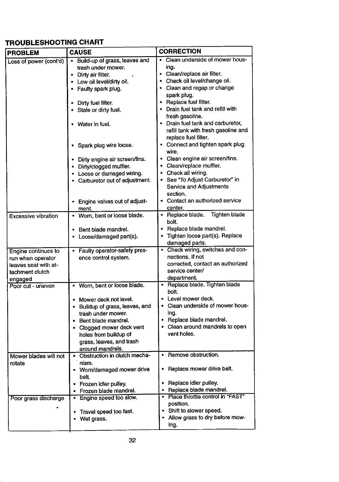
TROUBLESHOOTING CHART
CAUSE
• Build-upof grass, leaves and
trash under mower.
• Dirty air filter.
• Low oil level/dirty oil.
• Faulty spark plug.
• Dirty fuel filter.
• Stale or dirty fuel.
• Water in fuel.
PROBLEM
Loss of power (coot'd)
Excessive vibration
Engine continues to
run when operator
leaves seat with at-
tachment clutch
en_}a_ed
Poor cut - uneven
Mower blades will not
rotate
Poor grass discharge
• Spark plug wire loose.
• Dirty engine air screen/tins.
• Dirty/clogged muffler.
• Loose or damaged wiring.
• Carburetor out of adjustment.
• Engine valves out of adjust-
ment.
• Worn, bent or loose blade.
• Bent blade mandrel.
• Loose/damaged part(s).
• Faulty operator-safety pres-
ence controlsystem.
•Wom, bent or loose blade.
• Mower deck not level.
• Buildup of grass, leaves, and
trash under mower.
• Bent blade mandrel.
• Clogged mower deck vent
holes from buildup of
grass, leaves, and trash
around mandrels.
• Obstruction in clutchmecha-
nism.
• Worn/damaged mower drive
belt.
• Frozen idler pulley.
• Frozen blade mandrel.
• Engine speed too slow.
• Travel speed too fast.
• Wet grass.
CORRECTION
,
• Clean underside of mower hous-
ing.
• Clean/replace air tilter.
• Check oillevel/change oil.
• Clean and regap or change
spark plug.
• Replace fuel filter.
• Drain fuel tank and refill with
fresh gasoline.
• Drain fuel tank and carburetor,
refill tank withfresh gasoline and
replacefuel filter.
• Connect and tighten spark plug:
wire.
• Clean engine air screen/fins.
• Clean/replace muffler.
• Check allwiring.
• See "ToAdjust Carburetor" in
Service and Adjustments
section.
• Contact an authorized service
center.
• Replace blade. Tighten blade
bolt.
• Replace blade mandrel.
• Tighten loose part(s). Replace
damaged parts.
• Check wiring, switches and con-
nections. Ifnot
corrected, contact an authorized
service center/
department.
• Replace blade. Tighten blade
bolt.
• Level mower deck.
• Clean underside of mower hous-
ing.
• Replace blade mandrel.
• Clean around mandrels to open
vent holes.
• Remove obstruction.
• Replace mower drive belt.
• Replace idler pulley.
• Replace blade mandrel.
• Place throttle controlin "FAST"
position.
: • Shiftto slower speed.
• AllOWing..grass todry before mow-
32
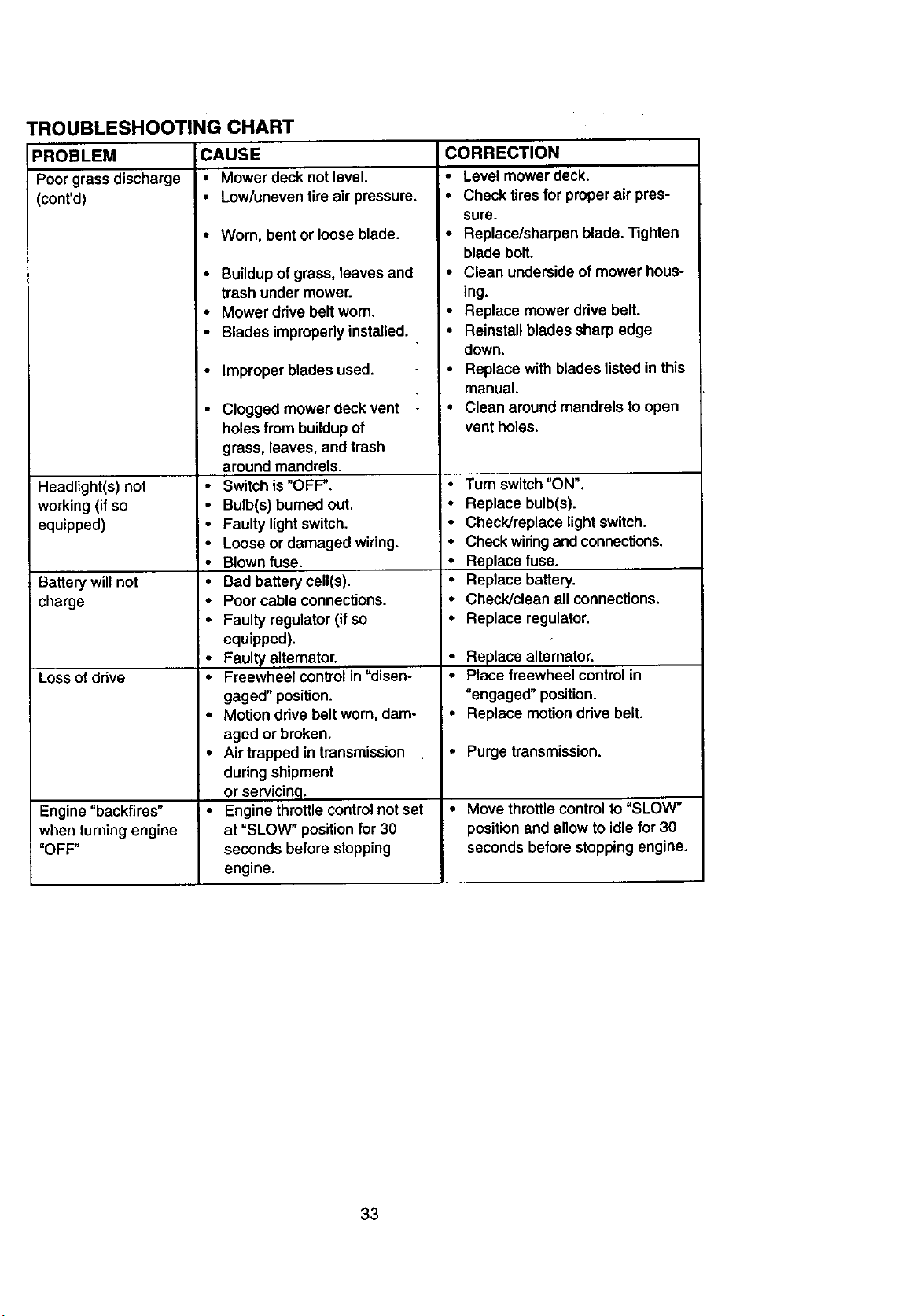
TROUBLESHOOTING CHART
PROBLEM CAUSE
Poor grass discharge • Mower deck not level.
(cont'd) • Low/uneven tire air pressure.
Headlight(s) not
working(if so •
equipped) •
Battery wilt not •
charge •
Loss of drive •
Engine "backfires" , •
when turning engine
"OFF"
Worn, bent or loose blade.
Buildup of grass, leaves and
trash under mower.
Mower drive belt worn.
Blades improperly installed.
Improper blades used.
Clogged mower deck vent
holes from buildup of
grass, leaves, and trash
around mandrels.
Switch is "OFF".
Bulb(s) bumed out.
Faulty light switch.
Loose or damaged wiring.
Blown fuse.
Bad battery cell(s).
Poor cable connections.
Faulty regulator (if so
equipped).
Faulty alternator.
Freewheel control in =disen-
gaged" position.
Motion drive belt worn, dam-
aged or broken.
Air trapped in transmission
during shipment
or servicin,q.
Engine throttle control not set
at "SLOW" position for 30
seconds before stopping
engine.
CORRECTION
• Level mower deck.
• Check tires for proper air pres-
sure.
• Replace/sharpen blade. Tighten
blade bolt.
• Clean undersideof mower hous-
ing.
• Replace mower drive belt.
• Reinstall blades sharp edge
down.
• Replace with blades listed in this
manual.
• Clean around mandrels to open
vent holes.
• Turn switch "ON".
• Replace bulb(s).
• Check/replace lightswitch.
• Check wiring and connections.
• Replace fuse.
• Replace battery.
• Check/clean all connections.
• Replace regulator.
• Replace altemator.
• Place freewheel controlin
"engaged" position.
• Replace motiondrive belt.
• Purge transmission.
• Move throttle control to "SLOW"
position and allow to idle for 30
seconds before stopping engine.
33
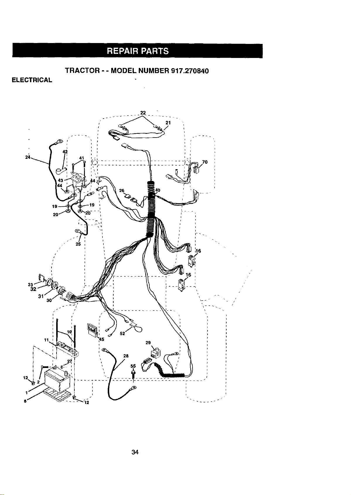
ELECTRICAL
TRACTOR - - MODEL NUMBER 917.270840
4_
i
41
22
21
26
i
L _
i
34
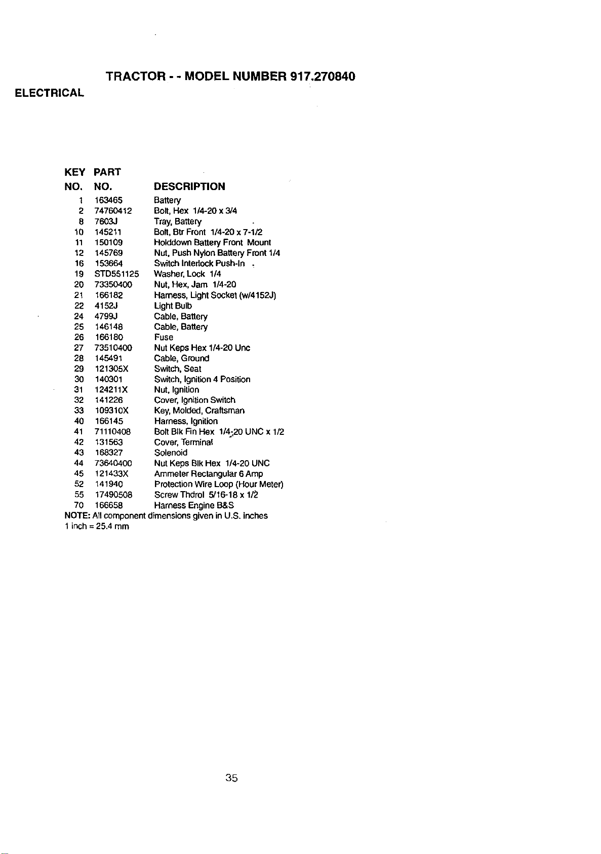
ELECTRICAL
TRACTOR - - MODEL NUMBER 917.270840
KEY PART
NO, NO. DESCRIPTION
t 163465 Battery
2 74760412 Bolt,Hex 1/4-20 x 3/4
8 7603J Tray, Battery •
10 145211 Bolt,Btr Front 1/4-20x7-1/2
11 150109 HolddownBatteryFront Mount
12 145769 Nut, Push NylonBatteryFront 1/4
16 153664 Switch IntedockPush-In
19 STD561125 Washer, Lock 114
20 73350400 Nut, Hex, Jam 1/4-20
21 166182 Harness, LightSocket (w/4152J)
22 41523 LightBulb
24 4799J Cable, Battery
25 146148 Cable, Battery
26 166180 Fuse
27 73510400 Nut Keps Hex 1/4-20 Unc
28 145491 Cable, Ground
29 121305X Switch,Seat
30 140301 Switch, Ignition4 Position
31 124211X Nut, Ignition
32 141226 Cover, IgnitionSwitch
33 109310X Key, Molded,Craftsman
40 166145 Harness, Ignition
41 71110408 Bolt BIk FinHex 1/4:.20UNC x 1/2
42 131563 Cover, Terminal
43 168327 Solenoid
44 73640400 Nut Keps BIk Hex 1/4-20 UNC
45 121433X Ammeter Rectangular6 Amp
52 141940 ProtectionWire Loop(Hour Meter)
55 17490508 Screw Thdrol 5/16-18 x 1/2
70 166658 Harness Engine B&S
NOTE: AIIcomponent dimensionsgiven inU.S. inches
1inch = 25.4 mm
35
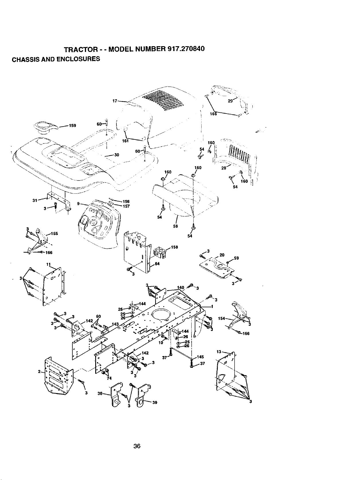
TRACTOR"" MODEL NUMBER 917.270840
CHASSIS AND ENCLOSURES
1
39_3 _ 39
$
36
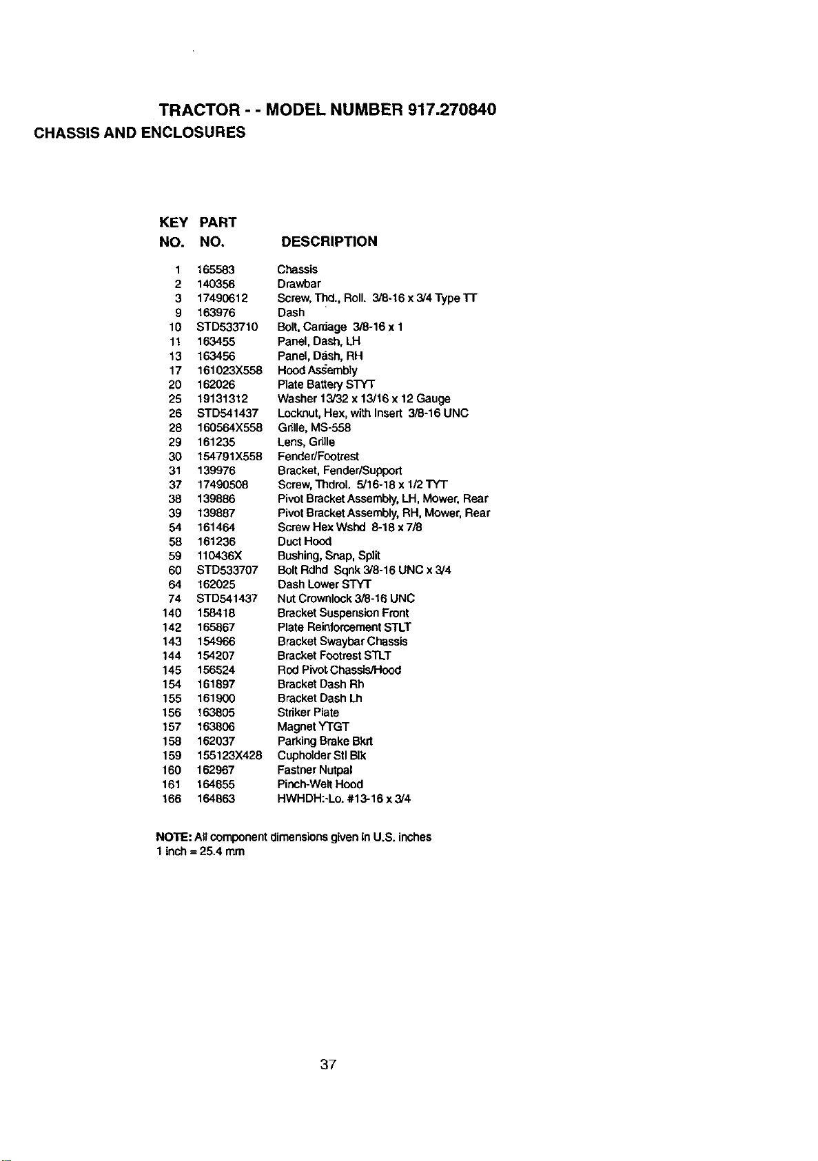
TRACTOR - - MODEL NUMBER 917.270840
CHASSIS AND ENCLOSURES
KEY PART
NO. NO. DESCRIPTION
1 165583 Chassis
2 140356 Drawbar
3 17490612 Screw,'rrld.,Roll. 3/8-16 x 3/4 Type"Fr
9 163976 Dash
10 STD533710 Bolt,Carriage 3/8-16 x 1
11 163455 Panel, Dash, LH
13 163456 Panel, D._sh,RH
17 161023X558 Hood Assembly
20 162026 Plate BatterySTY'I"
25 19131312 Washer 13/32 x 13/16 x 12 Gauge
26 STD541437 Locknut,Hex, withInsert 3/8-16 UNC
28 160564X558 Gdlle, MS-558
29 161235 Lens, Gdlle
30 154791X558 Fender/Footrest
31 139976 Bracket,Fender/Support
37 17490508 Screw,Thdrol. 5/16-18 x 1/2 "rYT
38 139886 PivotBracketAssembly,LH, Mower, Rear
39 139887 PivotBracketAssembly,RH, Mower, Rear
54 161464 ScrewHexWshd 8-18x7/8
58 161236 Duct Hood
59 110436X Bushing,Snap,Split
60 STD533707 Bolt Rdhd Sqnk 3/8-16 UNC x 3/4
64 162025 Dash LowerSTY'r
74 STD541437 Nut Crownlock3/8-16 UNC
140 158418 BracketSuspensionFront
142 165867 Plate ReinforcementSTLT
143 154966 Bracket SwaybarChassis
144 154207 Bracket FootrestSTLT
145 156524 Rod Pivot.Chassis/Hood
154 161897 Bracket DashRh
155 161900 Bracket DashLh
156 163805 StrikerPlate
157 163806 Magnet YTGT
158 162037 Parking Brake Bkrt
159 155123X428 CuphotderStlBIk
160 162967 FastnerNutpal
161 164655 Pinch-WeltHood
166 164863 HWHDH:-Lo. #13-16 x 3/4
NOTE: Allcomponentdimensions givenin U.S. inches
1 inch = 25.4 mm
37
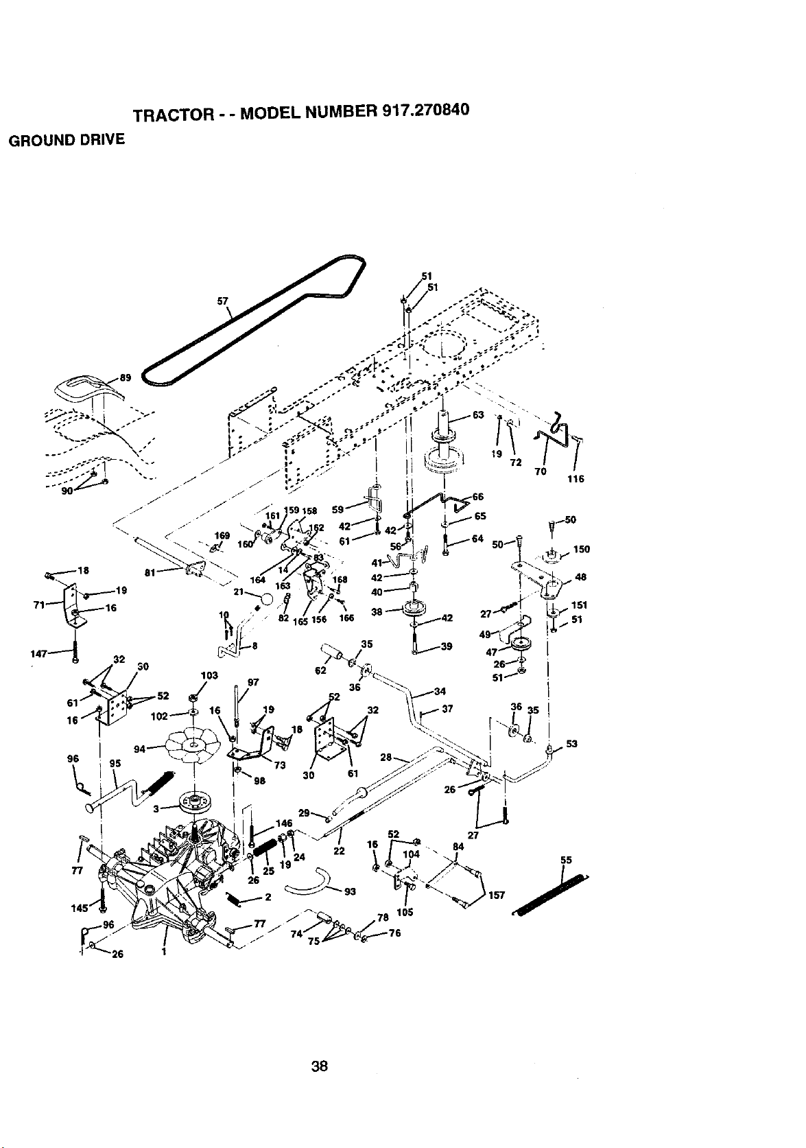
TRACTOR - - MODEL NUMBER 917.270840
GROUND DRIVE
22 104 "
77
27
84
55
38
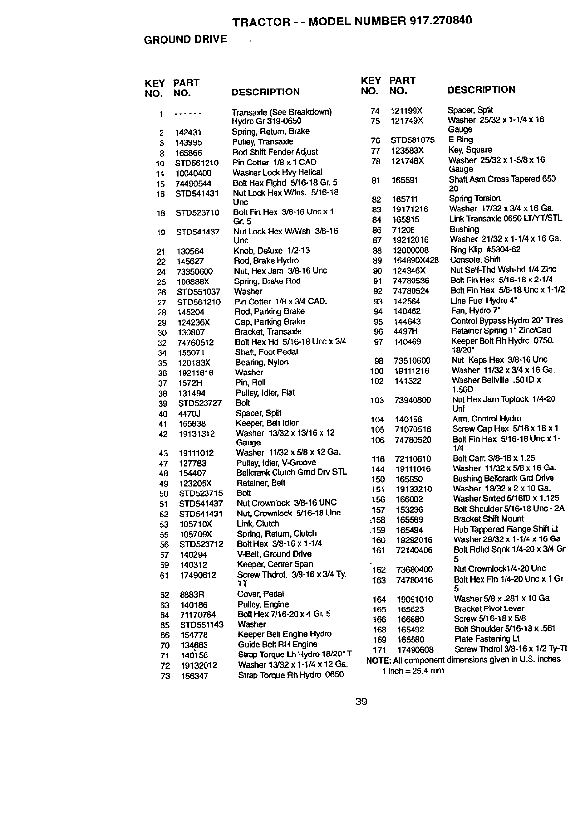
TRACTOR - - MODEL NUMBER 917.270840
GROUND DRIVE
KEY PART KEY PART
NO. NO. DESCRIPTION NO. NO.
1 ...... Transaxle (See Breakdown) 74 121199X
Hydro Gr 319-0650 75 121749X
2 142431 Spring,Return,Brake
3 143995 Pulley,Transsxle 76 STD581075
8 165866 RodShiftFenderAdjust 77 123583X
tO STD5612t0 PinCotter 118xlCAD 78 121748X
14 10040400 Washer LockHvyHelical
15 74490544 BoltHex Flghd 5/16-18 Gr. 5 81 165591
16 STD541431 NutLookHexW]lne. 5/16-18
Unc 82 165711
18 STD523710 BoltFinHex 3/8-16 Uncx 1 83 19171216
Gr.5 84 165815
19 STD541437 NutLockHexW/Wsh 3/8-16 86 71208
Unc 87 19212016
21 130564 Knob,Deluxe 1/2-13 88 12000008
22 145627 Rod, Brake Hydro 89 164890)(428
24 73950600 Nut, Hex Jam 3/8-16 Uric 90 124346X
25 106888X Spring,Brake Rod 91 74780536
26 STD551037 Washer 92 74780524
27 STD561210 Pin Cotter 1/8 x3/4 CAD. . 93 142564
28 145204 Rod, Parking Brake 94 140462
29 124236X Cap, Parking Brake 95 144643
30 130807 Bracket,Transaxle 96 4497H
32 74760512 Bolt Hex Hd 5/16-18 Uric x 3/4 97 140469
34 155071 Shaft, Foot Pedal
35 120183X Beadng,Nylon 98 73510600
36 19211616 Washer 100 19111216
37 1572H Pin,Roll 102 141322
38 131494 PuUey,Idler, Flat
39 STD523727 Bolt 103 73940800
40 4470J Spacer, Split
41 165836 Keeper, Belt Idler 104 140156
42 19131312 Washer 13/32x 13/16x 12 105 71070516
Gauge 106 74780520
43 19111012 Washer 11,32 x5/8 x 12Ga.
47 127783 Pulley,Idler,V-Groove 116 72110610
48 154407 BellcrankClutchGmd DrvSTL 144 19111016
49 123205X Retainer,Belt 150 165850
50 8TD523715 Bolt 151 19133210
51 STD541437 NutCrowntook 3/8-16UNC 156 166002
52 STD541431 Nut, Crownlook 5/16-18 Unc 157 153236
53 105710X L_k, Clutch :158 165589
55 105709X Spring, Return,Clutch .159 165494
56 STD523712 BoltHex 3/8.16x1-1/4 160 19292016
57 140294 V-BeJt,Ground Drive 161 72140406
59 140312 Keeper, Center Span
61 17490612 ScrewThdrol. 3/8-16x3/4Ty. 162 73680400
TT t63 74780416
62 8883R Cover, Pedal
63 140186 Pulley,Engine 164 19091010
64 71170764 BoltHex 7/16-20 x4 Gr, 5 165 165623
65 S'1-D551143 Washer 166 166880
66 154778 Keeper Belt EngineHydro 168 165492
70 134.683 Guide BeltRH Engine 169 165580
71 140158 Strap Torque Lh Hydro 18/20"T 171 17490608
72 19132012 Washer 13/32 x 1-1/4 x 12 Ga.
73 156347 StrapTorqueRhHydro 0650
DESCRIPTION
Spacer,Split
Washer 25/32 x 1-1/4 x 16
Gauge
E-Ring
Key,Square
Washer 25/32 x 1-5/8 x 16
Gauge
ShaftAsm CrossTapered 650
20
SpringTorsion
Washer 17/32 x3/4 x 16 Ga.
LinkTransaxla 0650 LT/YT/STL
Bushing
Washer 21/32 x 1-1/4 x 16 Ga.
RingKlip #5304-62
Console,Shift
Nut Setf-ThdWsh-hd 1/4 Zinc
Bolt FinHex 5/16-18 x 2-1/4
Bolt Rn Hex 5/6-18 Unox 1-1/;,
LineFuel Hydro4"
Fan, Hydro7"
ControlBypass Hydro20"-nres
RetainerSpdng 1* Zinc/Cad
Keeper Bolt Rh Hydro 0750,
18/20"
Nut Keps Hex 3/8-16 Uno
Washer 11/32 x3/4 x 18 Ga.
Washer Bellville .501D x
1.50D
NutHex Jam Toplock 114-20
Unf
Arm,ControlHydro
ScrawCap Hex 5/16 x 18 x 1
Bolt FinHex 5/16-18 Unc x 1-
1/4
BoltCarr. 3/8-16 x 1.25
Washer 11132x 5/8 x 16 Ga.
BushingBellcrankGrd Ddve
Washer 13/32x2x lOGa.
Washer Srrted5/161Dx 1.125
Bolt Shoulder5/16-18 Unc - 2t
BracketShiftMount
HubTapperod Range ShiftLt
Washer29/32 x 1-1/4 x 16Ga
Bolt RdhdSqnk 1/4-20 x 3/4 G
5
Nut Cmwnlockl/4-20 Unc
Belt Hex Rn 1/4-20 Unc x 1 G_
5
Washer5/8 x .281 x 10 Ga
BracketPivotLever
Screw5/16-18 x 5/8
Bolt Shoulder5/16-18 x ,561
PlateFasteningLt
ScrewThdrol3/8-16 x 1/2 Ty:l
NOTE: Allcomponentdimensionsgivenin U.S. inches
1inch= 25.4 mm
39
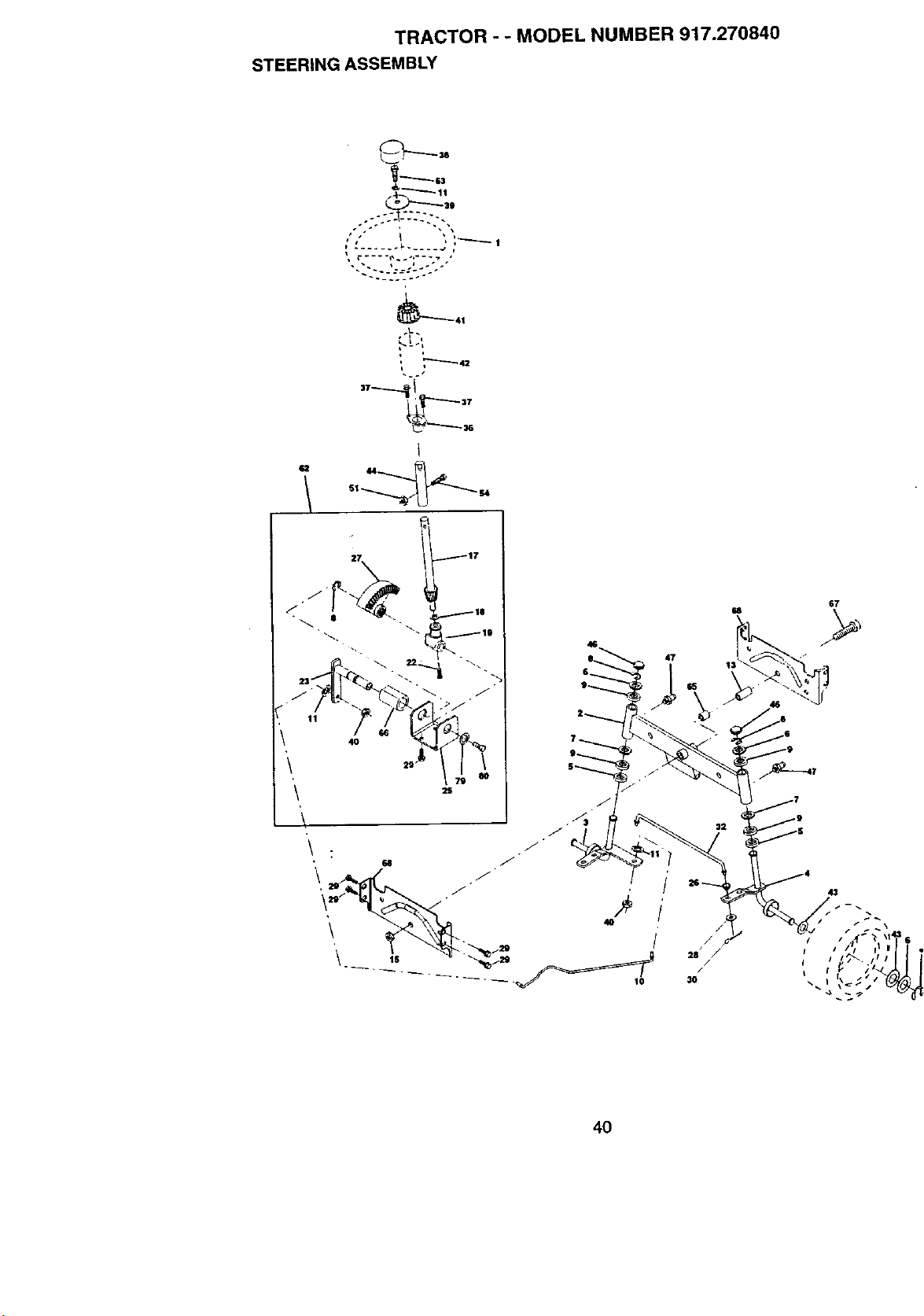
TRACTOR - - MODEL NUMBER 917.270840
STEERING ASSEMBLY
~. ..... .*
q
_÷
i
67
47
1:
4O
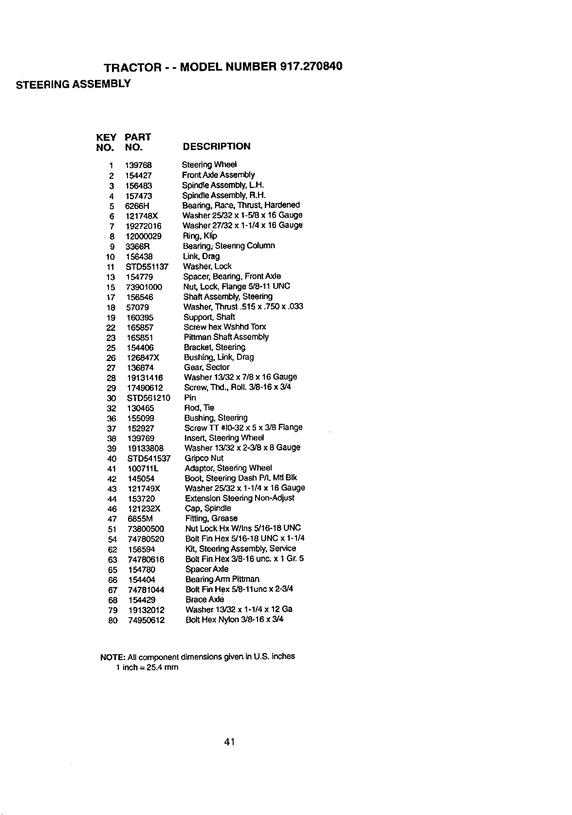
TRACTOR - - MODEL NUMBER 917.270840
STEERING ASSEMBLY
KEY PART
NO. NO. DESCRIPTION
1 139768
2 154427
3 156483
4 157473
5 6266H
6 121748X
7 19272016
8 12000029
9 3366R
10 156438
11 STD551137
13 154779
15 73901000
17 156546
18 57079
19 160395
22 165857
23 165851
25 154406
26 1268,47X
27 136874
28 19131416
29 17490612
30 STD561210
32 130465
36 155099
37 152927
38 139769
39 19133808
40 STD541537
41 100711L
42 145054
43 121749X
44 153720
46 121232X
47 6855M
51 73800500
54 74780520
62 156594
63 74780616
65 154780
66 154404
67 74781044
68 154429
79 19132012
80 74950612
SteeringWheel
FrontAxle Assembly
Spindle Assembly,L.H.
SpindleAssembly,R.H.
Beadng.Rare, Thrust. Hardened
Washer 25/32 x 1-5/8 x 16 Gauge
Washer 27/32 x 1-1/4 x 16Gauge
Ring, Klip
Beadng;Steering Column
Link, Drag
Washer, Lock
Spacer, Bearing, FrontAxle
Nut, Lock, Flange 5/8-11 UNC
ShaftAssembly, Steering
Washer, Thrust .515 x .756 x .033
Support,Shaft
Screwhex Wshhd Torx
PittmanShaft Assembly
Bracket, Steering
Bushing, Link,Drag
Gear,Sector
Washer 13/32 x7/8 x 16 Gauge
Screw,Thd,, Roll.3/8-16 x 3/4
Pin
Rod,Re
Bushing,Steering
Screw 17"#10-32x 5 x 3/8 Flange
Insert. Steering Wheel
Washer 13/32 x 2-3/8 x 6 Gauge
Gripco Nut
Adaptor,.SteedngWheel
Boot, Steering Dash P/L Mtl BIk
Washer 25/32 x 1-1/4 x 16 Gauge
Extension Steering Non-Adjust
Cap, Spindle
Fitting, Grease
Nut Lock Hx W/Ins 5/16-18 UNC
Bolt Fin Hex 5/16-18 UNC x 1-1/4
Kit, Steering Assembly, Service
Bolt Fin Hex 3/8-16 unc. x 1 Gr. 5
SpacerAx_e
BearingArm Plttman
BoltFinHex 5/8-11unc x 2-3/4
BraceAxle
Washer 13/32 x 1-1/4 x 12 Ga
Bolt Hex Nylon 3,'8.16 x3/4
NOTE: All componentdimensionsgiven in U.S. inches
1 inch= 25.4 mm
41
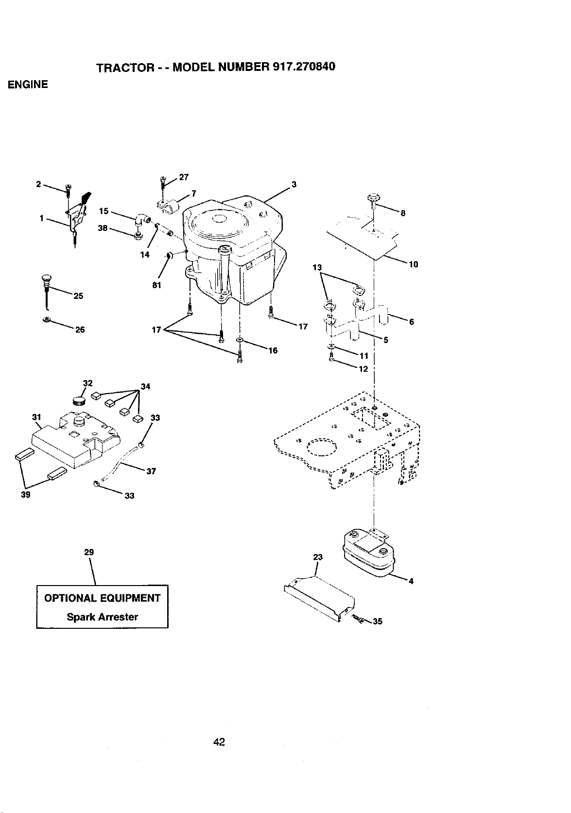
ENGINE
TRACTOR - - MODEL NUMBER 917.270840
31
39
2 w
14
_'_'_ 26
• 27
81
• __ _8
13 _10" _
.--':;"4-.
29
OPTIONAL EQUIPMENT I
Spark Arrester
/
4
42
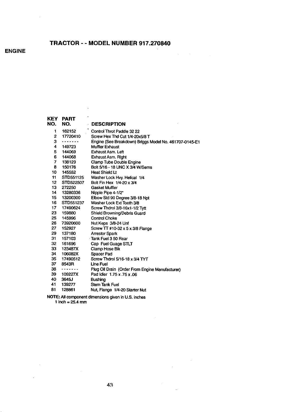
ENGINE
TRACTOR - - MODEL NUMBER 917.270840
KEY PART
NO. NO.
DESCRIPTION
1 162152
2 17720410
3 .......
4 149723
5 144069
6 144068
7 138129
8 150176
10 145552
11 STD551125
12 STD522507
13 272250
14 13280336
15 13200300
16 STD551237
17 17490624
23 159880
25 145996
26 73920600
27 152927
29 137180
31 157103
32 161696
33 123487X
34 106082X
35 17490512
37 8543R
38 .......
39 109227X
4O 3645J
41 139277
81 128861
ControlThrot Paddle 32 22
ScrewHex Thd Cut1/4-20x5/8 T
Engine(See Breakdown)BriggsModel No. 461707-0146-E1
MufflerExhaust
ExhaustAsro.Left
ExhaustAsro.Right
ClampTube DoubleEngine
Bolt5/16 - 18 UNC X 3/4 W/Sems
Heat ShieldLt
Washer LockHvy.Helical 1/4
Bolt FinHex 1/4-20 x 3/4
Gasket Muffler
NipplePipe4-1/2"
ElbowStd90 Degree 3/8-18 Npt
Washer Lock ExtTooth3/8
ScrewThdrol3/8-I 6x1-112Tytt
ShieldBrowning'DebrisGuard
ControlChoke
Nut Keps 3/8-24 Unf
ScrewTi" #10-32 x 5 x3/8 Flange
ArrestorSpark
-TankFuel3 50 Rear
Cap Fuel Guage STLT
ClampHose BIk
SpacerPad
ScrewThdrol5/16-18 x 3/4 TYT
LineFuel
PlugOil Drain (OrderFrom EngineManufacturer)
Pad Idler 1.75 x.75 x .06
Bushing
SternTank Fuel
Nut,Flange 1/4-20 StarterNut
NOTE: All componentdimensionsgivenin U.S. inches
1 inch= 25.4 mm
43
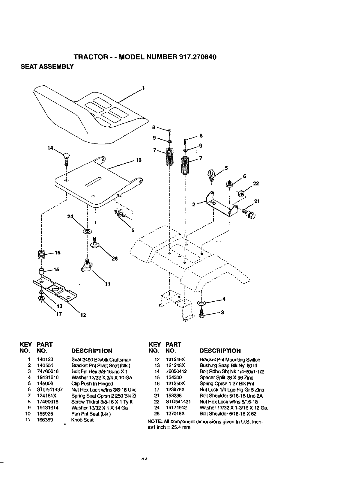
TRACTOR - - MODEL NUMBER 917.270840
SEAT ASSEMBLY
KEY PART
NO. NO.
1 140123
2 140551
3 74760616
4 19131610
5 145006
6 STD541437
7 124181X
8 17490616
9 19131614
10 155925
11 166369
KEY PART
NO. NO.DESCRIPTION
Seat3450 BIkJblkCraftsman 12 121246X
BracketPntPivotSeat (blk) 13 121248X
BoltFinHex 3/8-16unaX 1 14 72050412
Washer13,'32X 3/4 X 10 Ga 15 134300
Clip PushIn Hinged 16 121250X
NutHex Lockw/Ins3/8-16 Unc 17 123976X
SpringSeat Cprsn2 250 BIk Zi 21 153236
ScrewTi'_lrol3/8-16 X 1Ty-tt 22 STD541431
Washer 13/32 X 1X 14Ga 24 19171912
PanPnt Seat (blk) 25 127018X
KnobSeat
DESCRIPTION
BracketPntMounting Switch
BushingSnapBtkNy150 Id
Bolt RdhdSht Nk 1/4-20xl-1/2
SpacerSplit28 X 96 Zinc
Spdng CprsnI 27 BIkPnt
NutLock 114LgeFig Gr 5 Zinc
Bolt Shoulder5/16-18 Unc-2A
NutHex Lockw/ins5/16-18
Washer17/32 X 1-3/16 X 12 Ga.
BoltShoulder5/16-18 X 62
NOTE: All componentdimensionsgiven in U.S. inch-
esl inch = 25.4 mm
ttA
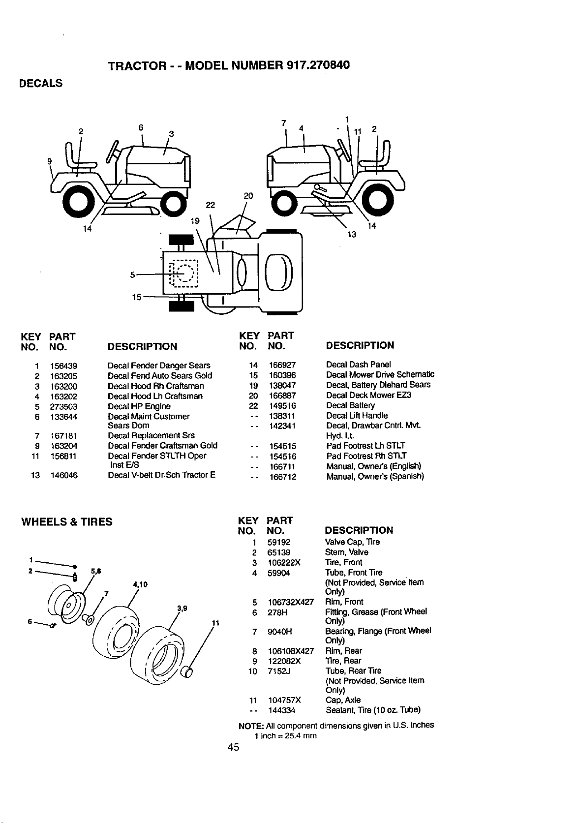
DECALS
TRACTOR - - MODEL NUMBER 917.270840
3
7
4
1
11 2
9
KEY PART
NO. NO.
1 156439
2 163205
3 163200
4 163202
5 273503
6 133644
7 167181
9 163204
11 156811
13 146046
14
2O
KEY PART
DESCRIPTION NO. NO.
Decal Fender Danger Sears 14 166927
Decal Fend Auto Sears Gold 15 160396
Decal Hood RhCraftsman 19 138047
Decal HoodLh Craftsman 20 166887
DecaIHPEngine 22 149516
Decal Maint Customer -* 138311
Sears Dom - - 142341
Decal Replacement Srs
Decal Fender Craftsman Gold - - 154515
Decal Fender STLTH Oper - - 154516
Inst EJS
- - 166711
Decal V-belt Dr.Scb TractorE
- - 166712
14
13
DESCRIPTION
Decal DashPanel
Decal Mower DdveSchematic
Decal, BatteryDiehardSears
Deca( Deck MowerEZ3
Decal Battery
Decal LiftH_ndle
Decal, DrawbarCntrl.Mvt.
Hyd. Lt.
Pad FeatmstLbSTLT
Pad FootrestRhSTLT
Manual, Owner's(English)
Manual, Owners (Spanish)
7
4,10
11
KEY PART
NO, NO. DESCRIPTION
1 59192 ValveCap, Tire
2 65139 Stem, Valve
3 106222X Tire, Front
4 59904 Tube, FrontTire
(Not Provided,ServiceItem
o_/)
5 106732)(427 Rim, Front
6 278H Fitting,Grease (FrontWheel
Only)
7 9040H Seadng, Range (Front Wheel
Only)
8 106108X427 Rim, Rear
9 122082X Tire, Rear
10 7152J Tube, RearTire
(Not Provided,ServiceItem
Only)
11 104757X Cap, Axle
- - 144334 Sealant,Tire (10 oz,Tube)
NOTE: All component dimensionsgivenin U.S.inches
1inch =25.4 mm
45
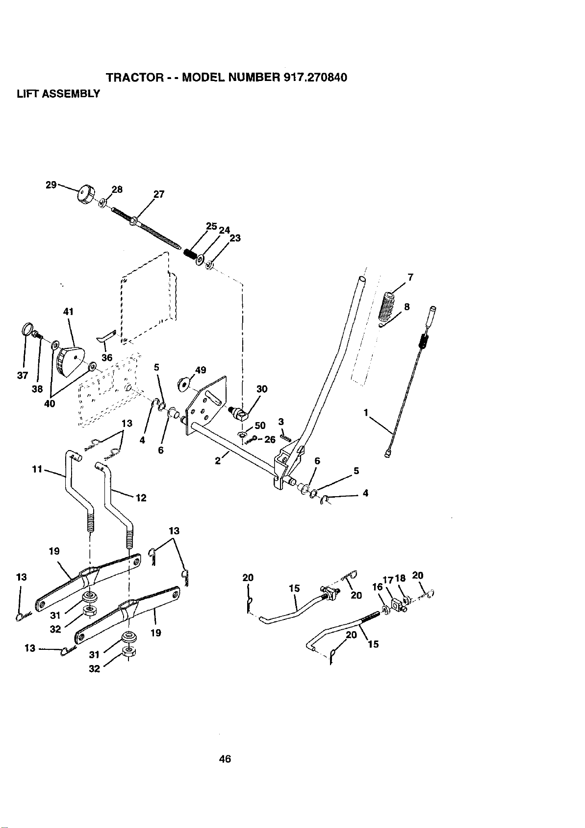
TRACTOR - - MODEL NUMBER 917.270840
LIFT ASSEMBLY
28 27
38
40
49
23
3
6
7
//// :/ , • 8/
5
4
19
13
13---o
19
13
46
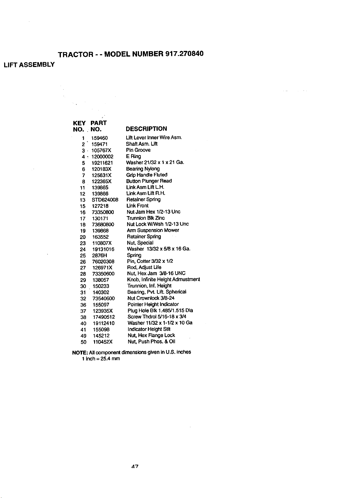
TRACTOR - - MODEL NUMBER 917.270840
LIFT ASSEMBLY
KEY PART
NO. NO. DESCRIPTION
1 159460 LiftLever InnerWire Asm.
2 " 159471 ShaltAsm. Lift
3 - 105767X Pin Groove
4 _ 12000002 E Ring
5 19211621 Washer 21/32 x t x 21 Ga.
6 120183X BearingNylong
7 125631X Grip Handle Fluted
8 122365X ButtonPlungerRead
11 139865 Link AsmLiftL-H.
12 139866 LinkAsmLiftR.H.
13 STD624008 RetainerSpring
15 127218 Unk Front
16 73350800 Nut Jam Hex 1/2-13Unc
17 130171 TrunnionBIkZinc
18 73680800 Nut LockW/Wsh 1/2-13 Unc
19 139868 Arm SuspensionMower
20 163552 RetainerSpring
23 110807X Nut, Special
24 19131016 Washer 13/32 x5/8 x 16 Ga.
25 2876H Spring
26 76020308 Pin, Cotter 3/32 x 1/2
27 126971X Rod,Adjust I ire
28 73350600 Nut, Hex Jam 3/8-16 UNC
29 138057 Knob, Infinite HeightAdmustment
30 150233 Trunnion, Inf. Height
31 140302 Bearing, Pvt.Lift.Spherical
32 73540600 Nut Cruwnlock3/8-24
36 155097 PointerHeightIndicator
37 123935X PlugHole Blk1.485/1.515 Dia
38 17490512 ScrewThdrol5/16-18 x 3/4
40 19112410 Washer 11/32x 1-1/2 x 10 Ga
41 155098 IndicatorHeightStir
49 145212 Nut,Hex Flange Lock
50 110452X Nut, PushPhos.&Oil
NOTE: All componentdimensionsgiven inU.S. inches
1 inch= 25.4 mm
47
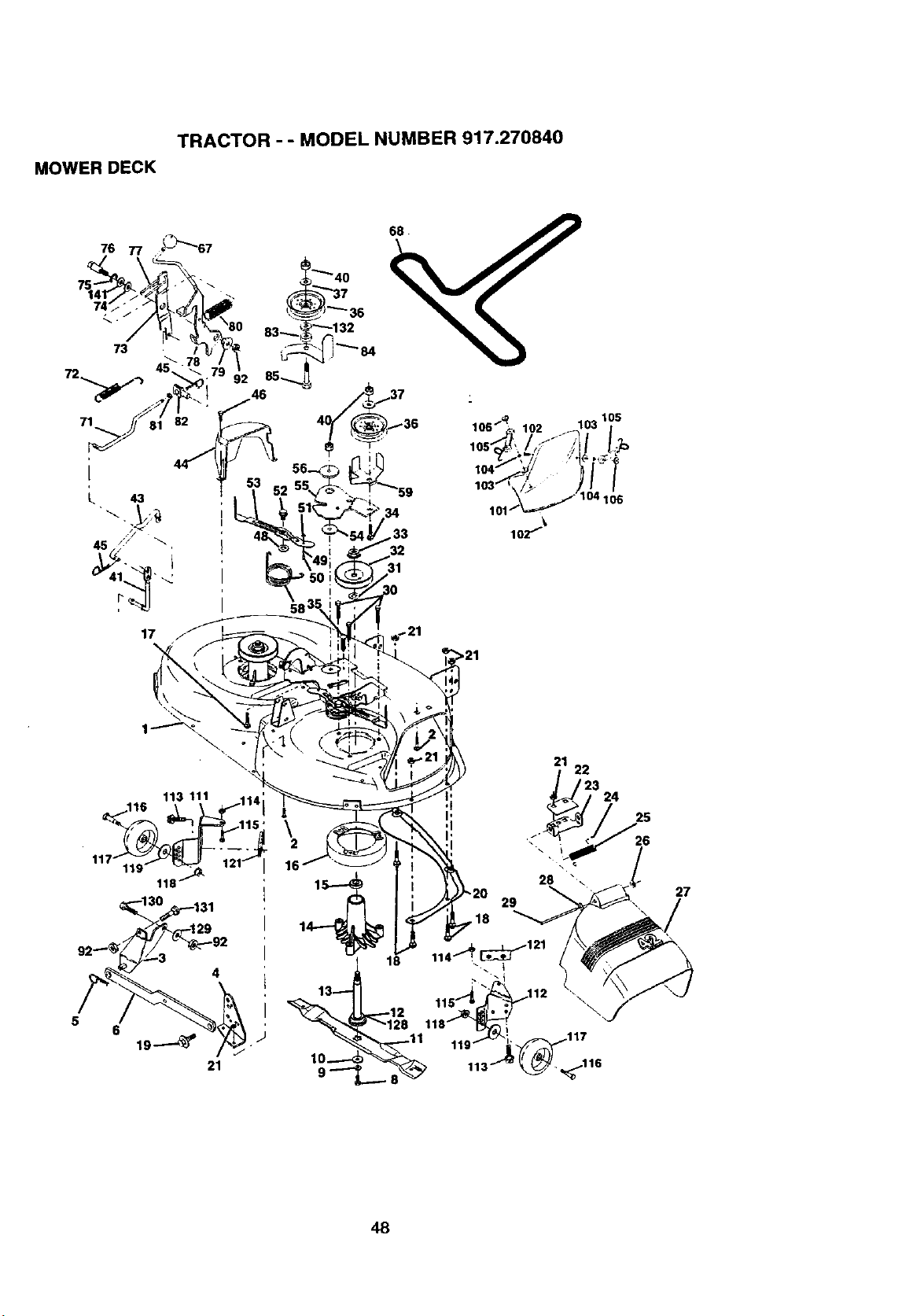
TRACTOR - - MODEL NUMBER 917.270840
MOWER DECK
31
106
17
>21
113 111 114'
/ 115 '
4
\
29
,18
27
48
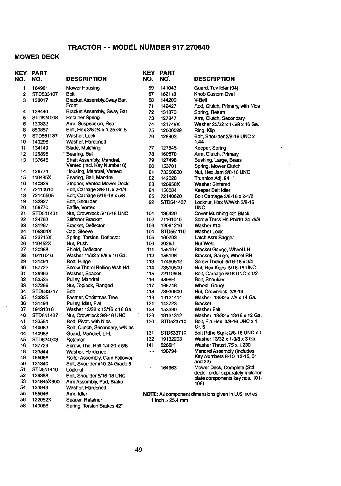
TRACTOR - - MODEL NUMBER 917.270840
MOWER DECK
KEY PART KEY PART
NO. NO. DESCRIPTION NO. NO.
1 164961 Mower Housing 59 141043
2 STD533107 Bolt 67 162113
3 138017 BracketAssembly,SwayBar, 68 144200
Front 71 142427
4 138440 BracketAssembly,Sway Bar 72 131870
5 STD624008 RetainerSpring 73 127847
6 130832 Arm, Suspension,Rear 74 121748X
8 850857 "Bolt,Hex 3/8-24 x 1.25 Gr.8 75 12000029
9 STD551137 . Washer,Lock 76 128903
10 140296 Washer,Hardened
11 134149 "Blade, Mulching 77 127845
12 129895 _Bearing,Ball 78 160570
13 137645 ShaftAssembly,Mandrel, 79 127498
Vented(Incl.Key Number6) 80 153701
14 128774 Housing,Mandrel,Vented 81 73350600
15 110485X Bearing,Ball,Mandrel 82 142028
16 140329 Stripper,VentedMower Deck 83 120958X
17 72110610 Bolt,Carriage 3/8-16 x 2-1/4 84 156084
18 72140505 Bolt,Carriage 5/16-18 x5/8 85 72140620
19 132827 Bolt,Shoulder 92 STD541437
20 159770 Baffle, Vortex
21 STD541431 Nut, Crownlock5/16-18 UNC 101 136420
22 134753 StiffenerBracket 102 71161010
23 131267 Bracket,Deflector 103 19061216
24 105304X Cap, Sleeve 104 STD551110
25 123713X Spring,Torsion,Deflector 105 160793
26 110452X Nut, Push 106 2029J
27 130968 Shield, Deflector 111 155197
28 19111016 Washer11/32x5i8x16Ga. 112 155198
29 131491 Rod, Hinge 113 17490512
30 157722 ScrewThdrolRollingWshHd 114 73510500
31 129963 Washer,Spacer 115 72110504
32 153535 .Pulley, Mandrel 116 4898H
33 137266 Nut,Topiock,Flanged 117 165746
34 STD533717 Bolt 118 73930600
35 133835 Fastner,ChristmasTree 119 19121414
36 131494 Pulley,Idler,Flat . 121 143723
37 19131316 Washer13/32 x13/16 x16 Ga. 126 153390
40 STD541437 Nut, Cmwnlock3i8-16UNC 129 19131312
41 133551 Rod, Pivot,with Nibs 130 STD523710
43 140083 Rod, Clutch,Secondary, w/Nibs
44 140088 Guard, Mandrel,L.H. 131 STD533710
45 STD624003 Retainer 132 19132203
46 137729 Screw,Thd. Roll 1/4-20 x 5/8 141 6266H
48 133944 Washer, Hardened - - 130794
49 155066 RollerAssembly,Cam Follower
50 131340 Bolt,Shoulder#10-24 Grade 5
51 STD541410 Locknut -- 164963
52 139888 Bait, Sheulders/16-18 UNC
53 131845X900 ArmAssembly,Pad, Brake
54 133943 Washer,Hardened
55 155046 Arm, Idler
56 122052X Spacer, Retainer
58 140086 Spring,TorsionBrakes42"
DESCRIPTION
Guard,Tuv Idler(94)
KnobCustomOval
V-Belt
Rod,Clutch,Primary,with Nibs
Spring,Return
Arm, Clutch,Secondary
Washer 25/32 x 1-5/8 x 16 Ga.
Ring,Klip
Bolt,Shoulder3/8-16 UNC x
1.44
Keeper, Spring
Arm,Clutch, Primary
Bushing,Large, Brass
Spring,Mower Clutch
Nut,Hex Jam 3/8-16 UNC
TrunnionAdj. 94
Washer Sintered
Keeper Belt Idler
BoltCarriage3/8-16 x2-1/2
Locknut,HexW/Wsh 3/8.16
UNC
Cover Mulching42=Black
ScrewTrussHd Phil10-24 x5/8
Washer #10
Washer Lock
LatchAsm Bagger
Nut Weld
Bracket Gauge,Wheel LH
Bracket,Gauge, Wheel RH
Screw11xIml 5/16-18 x3/4
Nut, Hex Kepe 5/16-18 UNC
Bolt,Carriage 5/16 UNC x 1/2
Bolt,Shoulder
Wheel, Gauge
Nut,Cmwnlock 3/8-16
Washer 13/32 x7/8 x14 Ga.
Bracket
Washer Felt
Washer 13/32 x 13/16 x12 Ga.
Bolt,Fin Hex 3/8-16 UNC x 1
Gr.5
BoltRdhdSqnk3/8-16 UNC x 1
Washer 13/32 x 1-3/8x 3 Ga.
WasherThrust.75 x1.230
MandrelAssembly(Includes
Key Numbers8-10, 12-15, 31
and 32)
Mower Deck. Complete (Std
deck- orderseparatelymulcher
platecomponents key nes. 101-
106)
NOTE: AUcomponent dimensionsgivenin U.S.inches
1inch= 25.4 mm
49
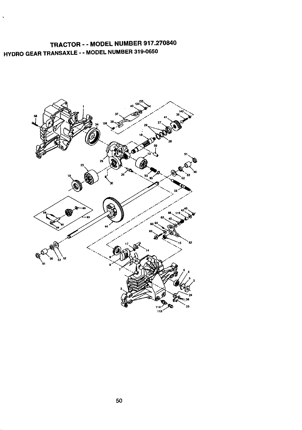
TRACTOR - - MODEL NUMBER 917.270840
HYDRO GEAR TRANSAXLE - - MODEL NUMBER 319-0650
58
41
26
59
26
23
1 25
3O
91
go
53
$1_ 35
113
50
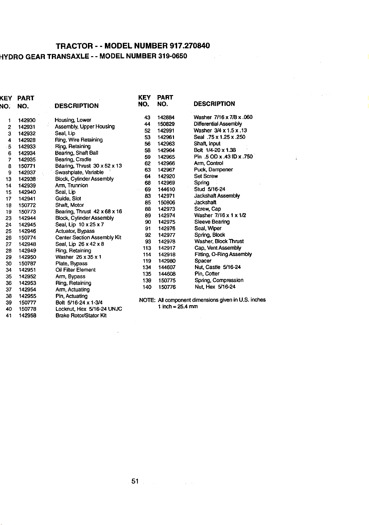
TRACTOR - - MODEL NUMBER 917.270840
_IYDRO GEAR TRANSAXLE - - MODEL NUMBER 319-0650
KEY PART KEY PART
NO: NO. DESCRIPTION NO. NO.
1 142930 Housing,Lower 43 142884
2 142931 : Assembly,Upper Housing 44 150829
3 142932 Seal, Lip 52 142991
4 142928 Rihg, WireRetaining 53 142961
5 142933 Ring, Retaining 56 142963
6 142934 Beadng,Shaft Ball 58 142964
7 142935 Bearing,Cradle 59 142965
8 150771 Beadng,Thrust 30 x52 x 13 62 142966
9 142937 Swashpiate, Variable 63 142967
13 142938 Block,CylinderAssembly 64 142920
14 142939 Arm, Trunnion 68 142969
15 142940 Seal, Lip 69 144610
17 142941 Guide,Slot 83 142971
18 150772 Shaft, Motor 85 150806
19 150773 Bearing,Thrust 42x68x16 88 142973
23 142944 Block,CylinderAssembly 89 142974
24 142945 Seal, Lip 10 x 25 x 7 90 142975
25 142946 Actuator,Bypass 91 142976
26 150774 Center SectionAssemblyKit 92 142977
27 142948 Seal, Lip 26 x 42 x 8 93 142978
28 142949 Ring, Retaining 113 142917
29 142950 Washer 26 x 35 x I 114 142918
30 150787 Plate, Bypass 119 142980
34 142951 Oil Filter Element 134 144607
35 142952 Arm, Bypass 135 144608
36 142953 Ring, Retaining 139 150775
37 142954 Arm, Actuating 140 150776
38 142955 Pin,Actuating
39 150777 Bolt 5/16-24 x 1-3/4
40 150778 Locknut,Hex 5/16-24 UNJC
41 142958 Brake Rotor/StatorKit
DESCRIPTION
Washer 7/16 x7/8 x .060
DifferentialAssembly
Washer 3/4 x 1.5 x .13
Seal .75 x 1.25 x .250
Shaft, input
Bolt 1/4-20 x 1.38
Pin .50D x A3 ID x .750
Arm, Control
Puck, Dampener
Set Screw
Spring
Stud 5/16-24
Jack.shaftAssembly
Jackshaft
Screw,Cap
Washer 7/16 x I x 1/2
Sleeve Bearing
Seal, Wiper
Spring,Block
Washer, BlockThrust
Cap, Vent Assembly
Fitting,O-RingAssembly
Spacer
Nut,Castle 5/16-24
Pin,Cotter
Spnng,Compression
Nut,Hex 5/16-24
NOTE: All componentdimensionsgiveninU.S. inches
1inch= 25.4 mm
51
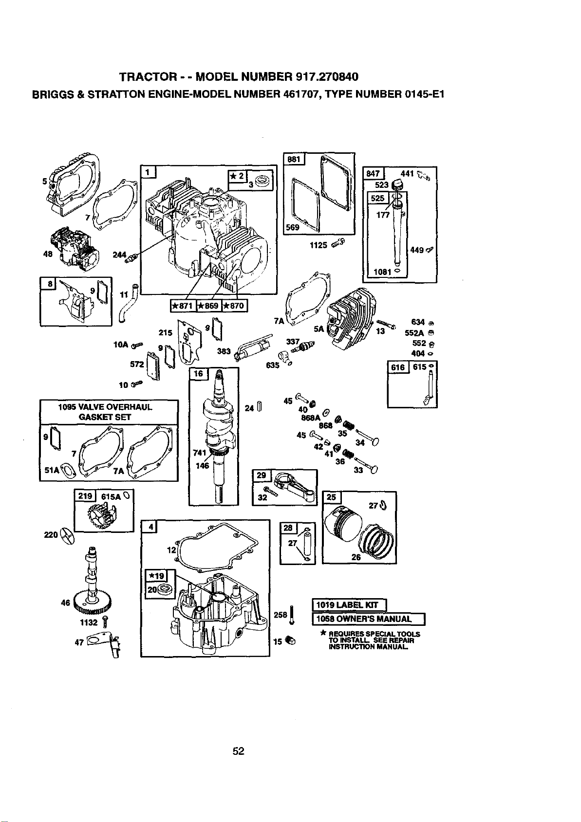
TRACTOR - - MODEL NUMBER 917.270840
BRIGGS & STRATTON ENGINE-MODEL NUMBER 461707, TYPE NUMBER 0145-E1
215
10A _p=
572
lO _P'
1095 VALVE OVERHAUL
GASKET SET
615A_
1132
_4_
552A
552
404
26
2SS_ 11019LABELKn" I
! 1058 OWNER'S MANUAL
llr REQUIRES SPECIAL TOOLS
15 _ TOINSTALLSEEREPAIR
INSTRUCTION MANUAL
52
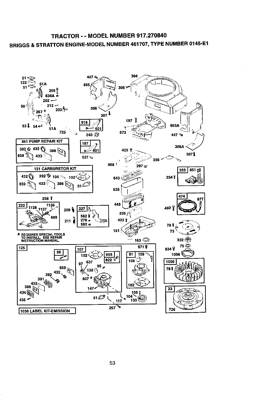
TRACTOR - - MODEL NUMBER 917.270840
BRIGGS & STRATrON ENGINE-MODEL NUMBER 461707, TYPE NUMBER 0145-E1
122 _"_ _ 51A
205
._ 202_-
50'-_ " 212 '-_
i':'_ 267 ' 203_
531t s4_ ""
51A •
725 :_
861 PUMP REPAIR KIT
392 _' 432 _', 386 I_
859_ 433 "_
304
306 _
307 L
240 ,_T
527
968 _ __ 297
643 _ '_"_
636! I ......
_-_
445 _
235 _
4231 /_
161 _ --
163 _._
121 CARBURETOR KIT I
I
859 _, 433 386 ITS[, 51_
258 _'
_.. 1138 11:_6,..J
1137 ,_
_1 652__-! I
_'_'_ "1 _z _ I
"k REQUIRESSPECIALTOOLS
TOINSTALL SEE REPAIR
INSTRUCTIONMANUAL
859
3013:2_2 "_ _'1
36643 %
4_ "
435 _"
1036 LABEL KIT-EMISSION
I07J _ 971 9
102 _._:----_ I'9"_'-_ 91 I 109 _
o7o37 _ lOO_
95 ,_
807 _ _ /_"_= _
,_i_,. 102_
147 ', _ ,' 106_
51_ t,,,. 117/'-,_10_33_
267 "_
306A
307_
"_6_#_::.:__
73 '_ _'
332 _:_
934_ 75_
1006
53
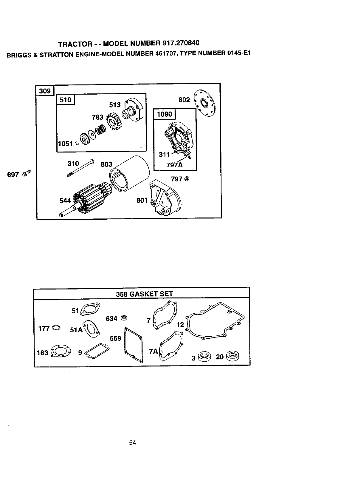
TRACTOR ' - MODEL NUMBER 917.270840
BRIGGS & STRATTON ENGINE-MODEL NUMBER 461707, TYPE NUMBER 0145-E1
697
783
1051 _,
y 803
544
513
797
801
358 GASKET SET
O
634 _ 7
177© 51A_ 569 _ 1U_:_
,o._Z>°<h _,
54
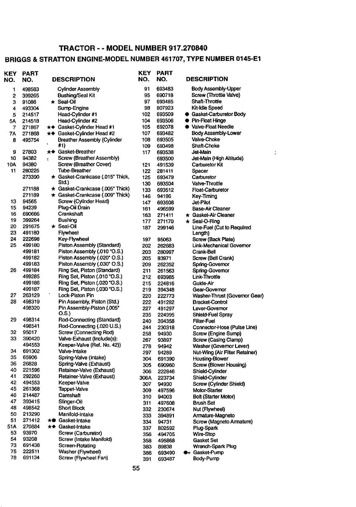
TRACTOR - - MODEL NUMBER 917.270840
BRIGGS & STRATTON ENGINE-MODEL NUMBER 461707, TYPE NUMBER 0145-E1
KEY PART KEY PART
NO. NO. DESCRIPTION NO. NO. DESCRIPTION
1 498583 CylinderAssembly 91 693483 BodyAssembly-Upper
2 399265 Bushing/SealKit 95 690718 Screw(ThrottleValve)
3 91086 '/r Seal-Oil 97 693485 Shaft-Throttle
4 493304 Sump-Engine 98 807923 Kit-IdleSpeed
5 214517 Head-Cylinder#1 102 693509 • Gasket-CarbumtorBody
5A 214518 Head-Cylinder #2 104 693506 • Pid-FIoatHinge
7 271867 ,/_ Gasket-Cylinder Head #1 105 692078 • Valve-RoarNeedle
7A 271868 .k_ Gasket-Cylinder Heed #2 107 693482 BodyAssembly-Lower
8 495754 BreatherAssembly(Cylinder 108 693505 Valve-Choke
#1) 109 693498 Shaft-Choke
9 27803 _r4, Gasket-Breather 117 693538 Jet-Main
10 94382 _ Screw (Breather Assembly) 693500 Jet-Main (HighAltitude)
10A 94380 Screw (BreatherCover) 121 491539 CarburetorKit
11 280225 Tube-Breather 122 281411 Spacer
273390 -/r Gasket-Crenkcase(.O15"Tblck, 125 693479 Carburetor
Std.) 130 693504 Valve-Throttle
271188 • Gasket-Crankcase (.005"Thick) 133 693512 Float-Carburetor
271189 -/r Gasket-Crankcase (.009"Thick) 146 94196 Key-_ming
13 94565 Screw (CylinderHead) 147 693508 Jet-Pilot
15 94239 Plug-OilDrain 161 496599 Base-AlrCleaner
16 690666 Crankshaft 163 271411 ./r Gasket-AlrCleaner
19 399264 Bushing 177 271170 "JrSeal-O-Ring
20 291675 _r Seal-Oil 187 299146 Line-Fuel (CuttoRequired
23 491180 Flywheel Length)
24 222698 Key.Flywbeel 197 95063 Screw (BackPlate)
25 499180 PistonAssembly(Standard) 202 262683 Unk.Mechanica! Governor
499181 PistonAssembly (.010 "O.S.) 203 280997 Crank-Bell
499182 PistonAssembly (.020" O.S.) 205 93971 Screw (BellCrank)
499183 PistonAssembly (.030" O.S.) 209 262352 Spring-Governor
26 499184 Ring Set, Piston (Standard) 211 261563 Spring-Governor
499285 Ring Set. Piston (.010 "O.S.) 212 693985 Link-Throftle
499186 Ring Set, Piston (.020"O.S.) 215 224816 Guide-Air
499187 Ring Set, Piston (.030"O.S.) 219 394348 Gear-Gevemor
27 263129 Lock-PistonPin 220 222773 Washer-Thrust(GovernorGear)
28 498319 Pin Assembly, Piston(Std.) 222 491282 Brecket-Contml
498320 PinAssembly-Piston(.005" 227 491297 Lever-Governor
O.S.) 235 224995 Shield-FuelSpray
29 498314 Rod.Connecting(Standard) 240 394358 Filter-Fuel
498541 Rod-Connecting(.020 U.S.) 244 230318 Connector-Hose(Pulse Line)
32 95017 Screw (ConnectingRod) 258 94930 Screw (Engine Sump)
33 390420 Valve-Exhaust(Include(s): 267 93897 Screw (CasingClamp)
494553 Keeper-Valve (Ref. No. 42)) 278 94942 Washer(GovernorLever)
34 691302 Valve-Intake 297 94289 Nut-Wing(AirFilterRetainer)
35 65906 Spring-Valve(Intake) 304 691390 Housing-Blower
36 26828 Spring-valve (Exhaust) 305 690960 Screw (BlowerHousing)
40 221596 Retainer-Valve(Exhaust) 306 222846 Shield,Cylinder
41 292260 Retainer-Valve(Exhaust) 306A 223734 Shield-Cylinder
42 494553 Keeper-Valve 307 94930 Screw(CylinderShield)
45 261368 Tappet-Valve 309 497596 Motor-Starter
46 214487 Camshaft 310 94003 Bolt (StarterMotor)
47 393415 Slinger-OU 311 497608 BrushSet
48 498542 Shod Block 332 230674 Nut (Flywheel)
50 213290 Manifold-intake 333 394891 Armature-Magneto
51 271412 ./tO Gasket-intake 334 94731 Screw (MagnetoArmature)
51A 270884 _r_ Gasket-Intake 337 802592 Plug-Spark
53 93970 Screw (Carburetor) 356 494705 Wire-Stop
54 93208 Screw (IntakeManifold) 358 495868 Gasket Set
73 691438 Screen-Rotating 383 89838 Wrench-Spark Plug
75 222511 Washer(Flywheel) 386 693490 •+ Gasket-Pump
76 691134 Screw (FlywheelFan) 391 693487 Body-Pump
55
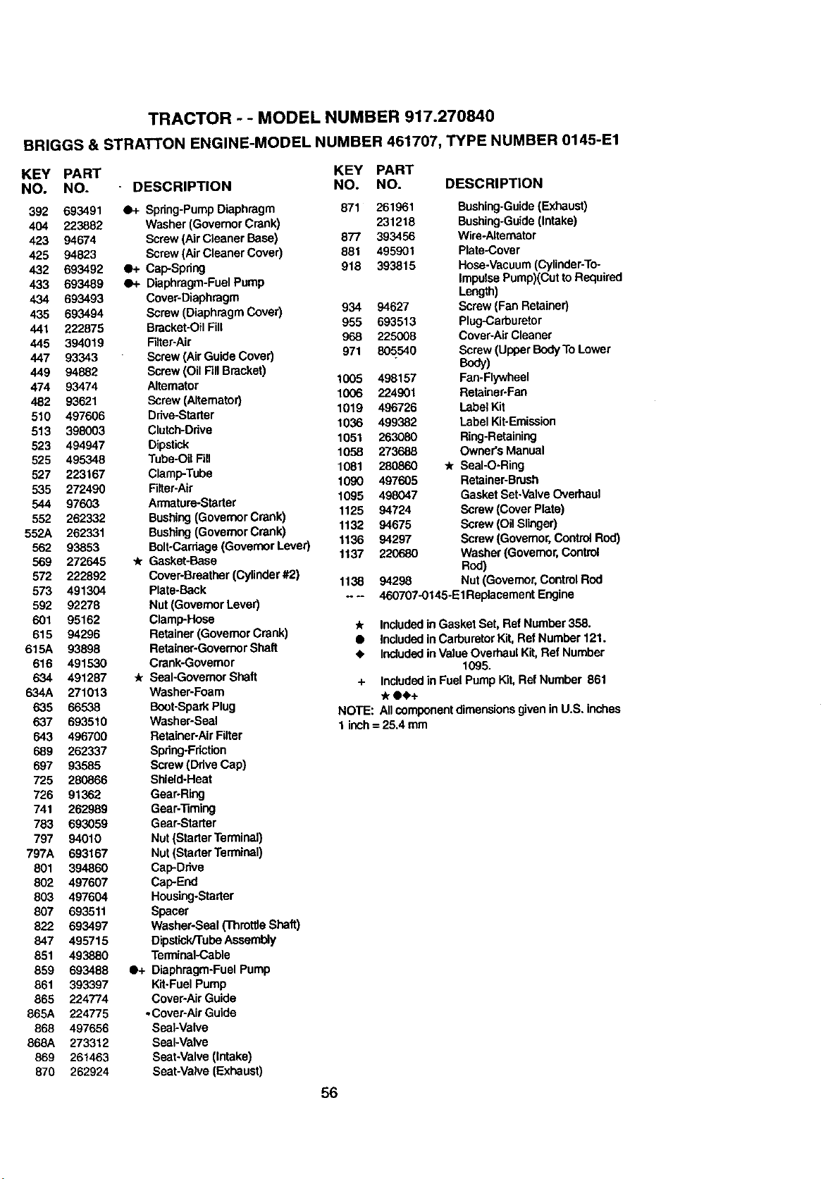
TRACTOR - - MODEL NUMBER 917.270840
BRIGGS & STRATTON ENGINE-MODEL NUMBER 461707, TYPE NUMBER 0145-E1
KEY PART KEY PART
NO. NO. - DESCRIPTION NO. NO. DESCRIPTION
392 693491 a_- Spdng-Pump Diaphragm
404 223882 Washer (GovernorCrank)
423 94674 Screw (Air Cleaner Base)
425 94823 Screw (Air Cleaner Cover)
432 693492 4_- Cap-Spdng
433 693489 •+ Diaphragm-FuelPump
434 693493 Cover-Diaphragm
435 693494 Screw (DiaphragmCover)
441 222875 Bracket-OilFill
445 394019 Filter-Air
447 93343 Screw (Air GuideCover)
449 94882 Screw (Oil FillBracket)
474 93474 Altamator
482 93621 Screw (Altemator)
510 497606 Drive-Starter
513 398003 Clutch-Ddve
523 494947 Dipstick
525 495348 Tube-Oil Fill
527 223167 Clamp-Tube
535 272490 Filter-Air
544 97603 Armature-Startar
552 262332 Bushing(GovernorCrank)
552A 282331 Bushing(GovemorCrank)
562 93853 Bolt-Carriage(GovernorLever)
569 272645 "k Gasket-Base
572 222892 Cover-Broathar(Cylinder#2)
573 491304 Plata-Back
592 92278 Nut (GovernorLever)
601 95162 Clamp-Hose
615 94296 Retainer (GovernorCrank)
615A 93898 Retainer-GovemorShaft
616 491530 Crank-Governor
634 491287 _ SeaI.GovemorShaft
634A 271013 Washer-Foam
635 66538 Boot-SparkPlug
637 693510 Washer-Seal
643 496700 Retainer-AirFilter
689 262337 Spdng-Fdction
697 93585 Screw (Ddve Cap)
725 280866 Shield-Heat
726 91362 Gear-Ring
741 262989 Gear-'13ming
783 693059 Gear-Starter
797 94010 Nut (StarterTerminal)
797A 693167 Nut (StarterTerminal)
801 394860 Cap-Drive
802 497607 Cap-End
803 497604 Housing-Starter
807 693511 Spacer
822 693497 Washer-Seal (ThrottleShaft)
847 495715 Dipatick/Tube Assembly
851 493880 Terminal-Cable
859 693488 •+ Diaphragm-FuelPump
861 393397 Kit-FuelPump
885 224774 Cover-AirGuide
865A 224775 oCover-Air Guide
868 497656 SeaFValve
868A 273312 Seal-Valve
869 261463 Seat-Valve(intake)
870 262924 Seat-Valve (Exhaust)
934
955
968
971
1005
1006
1019
1036
1051
1058
1081
1090
1095
1125
1132
1136
1137
11_ 942_
N_
871 261961 Bushing-Guide(Exhaust)
231218 Bushing-Guide(Intake)
877 393456 Wire-Alternator
881 495901 Plata-Cover
918 393815 Hose-vacuum (Cylinder-To-
Impulse Pump)(Cutto Required
Length)
94627 Screw (Fan Retainer)
693513 Plug-Carburetor
225008 Cover-AirCleaner
805540 Screw (UpperBodyTOLower
BoW)
498157 Fan-Flywheal
224901 Retainer*Fan
496726 Label Kit
499382 Label Kit-Emission
263080 Ring-Retaining
273688 Owners Manual
280860 -/r Seal-O-Ring
497605 Retainer-Brush
498047 GasketSet-ValveOverhaul
94724 Screw (Cover Plate)
94675 Screw (Oil Slinger)
94297 Screw(Governor,Control Rod)
220680 Washer(Governor,Control
Rod)
Nut (Governor,ControlRod
460707-0145-EIReplacement Engine
_r Includedin GasketSet, Ref Number358.
• Included inCarburetorKit, Ref Number 121.
• IncludedinValue OverhaulKit,Ref Number
1095.
+ Included in Fuel Pump Kit, Ref Number 861
0•+
NOTE: Allcomponentdimensionsgiven in U.S. inches
1 inch= 25.4 mm
56
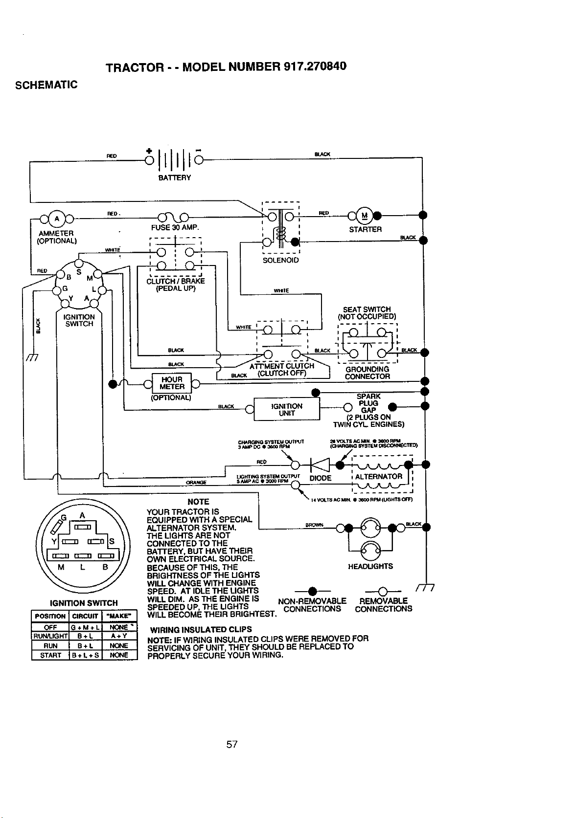
SCHEMATIC
TRACTOR - - MODEL NUMBER 917.270840
BATTERY
AMMETER
(OPTIONAL)
IGNITION
SWITCH
FUSE_AMP.
I
I
SEAT SW1TCH
(NOT OCCUPIED)
i ....... i i.-
J
mL_CK (CLUTCH OFF) GROUNDING
CONNECTOR
RED.
L------ .... J
CLUTCH / BRAKE
(PEDAL UP)
BLACK
8JJ,CK
(OPTIONAL)
IGNITION
UNiT
A
,IF SPARK
l (2 PLUGS ON
TWIN CYL ENGINES)
IGNITION SWITCH
OFF G+M+L NONE
RUN/UGHT B+L A÷Y
RUN B+ L NONE
START B+ L÷ S NONE
ORANGE
NOTE
YOUR TRACTOR IS
EQUIPPED WITH A SPECIAL
ALTERNATOR SYSTEM.
THE LIGHTS ARE NOT
CONNECTED TO THE
BATTERY, BUT HAVE THEIR
OWN ELECTRICAL SOURCE.
BECAUSE OF THIS, THE
BRIGHTNESS OF THE LIGHTS
WILL CHANGE WITH ENGINE
SPEED. AT IDLE THE LIGHTS
WILL DIM. AS THE ENGINE IS
SPEEDED UP, THE LIGHTS
HEADUGHTS
t) ----C---
NON-REMOVABLEREMOVABLE
CONNECTIONS CONNECTIONS
WILL BECOME THEIR BRIGHTEST.
WIRING INSULATED CLIPS
NOTE: IF WIRING INSULATED CLIPS WERE REMOVED FOR
SERVICING OF UNIT, THEY SHOULD BE REPLACED TO
PROPERLY SECURE YOUR WIRING.
57

58

SUGGESTED GUIDE FOR SIGHTING SLOPES FOR SAFE OPERATION
ONLY RIDE UP AND DOWN HILL,
NOT ACROSS HILL
i
d A Operate your Tractor up and down the face of slopes (not
Hi AUk greater than 15 ), never across the face. Make turns gradu-
Ii O ally to prevent tipping or loss of control. Exercise extreme
I caution when changing direction on slopes.
Forthe repair or replacement parts you need
delivered directly to your home
Call 7 am - 7 pro, 7 days a week
1-800-366-PART
(1.800-366-7278)
Para ordenar plezas con entrega a
domicilio - 1-800-659-7084
For in-house major brand repair service
Call 24 hours a day, 7 days a week
1-800-4-REPAIR
(1-800-473-7274)
Para pedir servicio de reparacl6n a
domicllio - 1-800-676-5811
For the location of a Sears Parts and
Repair Center in your area
Call 24 hours a day, 7 days a week
1-800-488-1222
For information on purchasing a Sears
Maintenance Agreement orto inquire
about an existing Agreement
Call 9 am - 5 pm, Monday-Saturday
1-800-827-6655
IilliI
mmmmm|
When requesting service or ordering
parts, always provide the following
information:
• ProductType • Part Number
• Model Number • Part Description
SF_ARS
Amenca's Repair Specia/tsts
166711 12.29.98 RD Pdntedin U.S.A.


