Blackmagic
Studio Cameras
Blackmagic Studio Cameras
December 2022
Installation and Operation Manual

Languages
To go directly to your preferred language, simply click on the hyperlinks listed in the
contents below.
English 3
日本語143
Français 284
Deutsch 425
Español 566
中文707
한국어 848
Русский 989
Italiano 1130
Português 1271
Türkçe 1412
Polski 1553
Українська 1694

Welcome
Thank you for purchasing a Blackmagic Studio Camera!
Blackmagic Studio Cameras have the same features as large studio cameras, miniaturized
into a single compact and portable design.
With increased dynamic range and Blackmagic Design color science, the cameras can
handle extremely difficult lighting conditions while producing cinematic looking images.
The dual gain sensor supports ISO up to 25,600 so you can create amazing images even
in dimly lit venues.
Advanced features include talkback, tally, camera control, built in color corrector,
Blackmagic RAW recording to USB disks, direct streaming and much more! You can even
add a focus and zoom demand for lens control!
We hope you use your new camera for some amazing live productions and produce some
fantastic looking work! We are extremely excited to see what creative work you produce!
Grant Petty
CEO Blackmagic Design
English

Contents
Which Studio Camera are you using? 6
Getting Started 7
Attaching a Lens 7
Plugging in Power 8
Turning Your Camera On 8
Setting the Frame Rate and Resolution 9
Connecting to an ATEM switcher 10
Connecting a Talkback Headset 12
Setting the ATEM Camera ID 13
Checking your Setup 13
Testing Program Return 13
Testing Tally 14
Recording Blackmagic RAW to USB 14
Studio Camera Connectors 15
Left Panel 15
Right Panel 16
5 Pin XLR Talkback Connector
Pinout Diagram
17
Using Studio Camera Controls 17
Using the ND Filters 20
Storage Media 21
USB-C Flash Disks 21
Preparing USB-C Flash Disks for
Recording
22
Preparing Media on a Mac 24
Preparing Media on a Windows PC 25
Touchscreen Controls 26
Changing Settings using the Head
up Display
26
Touchscreen Features 27
Touchscreen Gestures 47
Menu Settings 48
Record Settings 48
Blackmagic RAW 50
Recording to Blackmagic RAW 50
Record Duration 53
File Naming Convention 58
Monitor Settings 58
Audio Settings 65
Setup Settings 67
Presets 80
3D LUTs 82
Entering Metadata 85
Slate 85
Streaming Video 90
Smartphone Setup 92
Settings 92
Setting the ATEM Camera ID 93
Creating the XML File 93
Exporting the XML File 93
Loading the XML File 94
Using the Sun Hood 95
Blackmagic Zoom and Focus Demands 96
Connecting and Attaching to your
Camera
97
Using Blackmagic Focus Demand 99
Using Blackmagic Zoom Demand 99
Compatible Compact Servo Zoom
EF Mount Lenses 101
Compatible Micro Four Thirds Lenses 101
Blackmagic Studio Converter 102
Getting Started with Blackmagic
Studio Converter 102
Connectors 105
Using the Front Panel 107
Menu Settings 108
Monitor 108
Audio 109
Setup 110
Using the Monitor Output 112
Adapter Cables for Talkback and Tally 113
Talkback Pin Connections 113
DB-9 Tally / Audio in connector
pinout diagram 113
4Blackmagic Studio Cameras

Rack Mounting 114
Blackmagic Camera Setup 116
How to Update your Camera’s
Internal Software
116
Using ATEM Software Control 117
Camera Control 117
Camera Control Panel 117
DaVinci Resolve Primary Color Corrector 121
Developer Information 125
Blackmagic SDI Camera Control
Protocol
125
Example Protocol Packets 134
Blackmagic Embedded Tally
Control Protocol
135
Connecting Tally using the
Blackmagic3G-SDI Shield for Arduino
137
Help 139
Regulatory Notices 140
Safety Information 141
Warranty 142
5
Blackmagic Studio Cameras
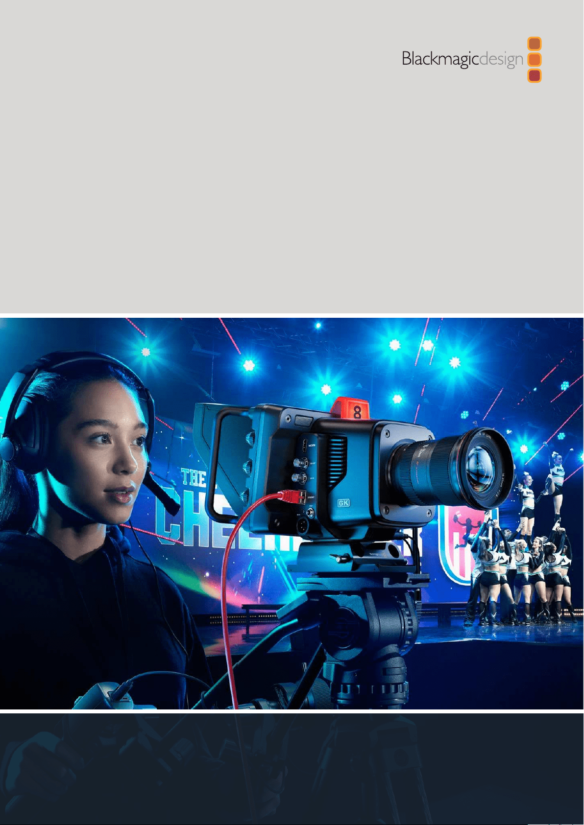
Which Studio Camera are you using?
Blackmagic Studio Cameras are designed to have similar features to large studio cameras,
miniaturized into a compact and more portable design. The cameras also feature wide dynamic
range and advanced color science, so they can handle difficult lighting conditions while
producing cinematic looking images.
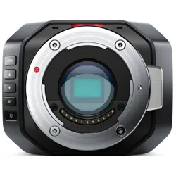
Blackmagic Studio Camera 4K Plus is the perfect studio camera for ATEM Mini HDMI switchers.
This model has a 4K sensor that supports up to 25,600 ISO, micro four thirds lens mount, HDMI
output, 7” LCD with sunshade, built-in color correction and will record Blackmagic RAW to USB
disks so you can edit and color grade your video in post production.
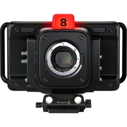
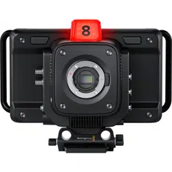
The advanced Blackmagic Studio Camera 4K Pro and 6K Pro models share all the features
of the Plus model, but add 12G-SDI for SDI based HD and Ultra HD ATEM switchers. Other
features include XLR audio, brighter HDR LCD, 5 pin XLR talkback plus a 10G Ethernet IP link
fora SMPTE fiber style workflow.
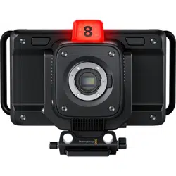
On Blackmagic Studio Camera 6K Pro and 4K Pro G2, their built in streaming engine lets you
stream video over the Internet or a local network via the 10G Ethernet connector, or by using a
smartphone connected via USB-C. This added streaming functionality means you can connect
your studio camera to a remote ATEM switcher using an ATEM Streaming Bridge.
The EF lens mount on Blackmagic Studio Camera 6K Pro lets you attach commonly available
high quality EF lenses, plus includes a high resolution 6K sensor and built in ND filters.
Blackmagic
Studio Camera 4K Plus
Blackmagic
Studio Camera 4K Pro and 4K Pro G2
Blackmagic
Studio Camera 6K Pro
6
Which Studio Camera are you using?
Getting Started
This section of the manual provides the basics on how to get started with your Blackmagic
Studio Camera.
Getting started is quick and easy! All you need to do is attach a lens, plug in power and turn
your camera on. You will immediately see the image on the built in touchscreen and can start
using your camera straight away!
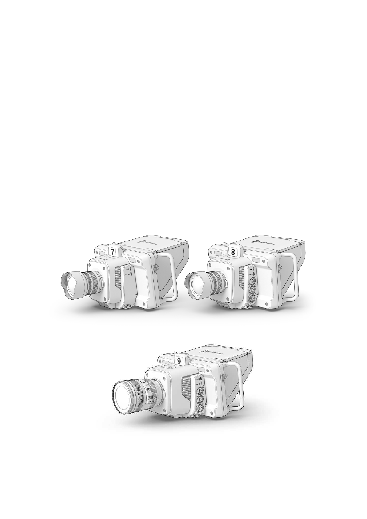
Attaching a Lens
Blackmagic Studio Camera 4K Plus and 4K Pro models use micro four thirds lenses, while
Blackmagic Studio Camera 6K Pro uses EF lenses. Attaching a lens to your camera is the same
process for all models. To remove the dustcap from the lens mount, hold down the locking
button and rotate the cap counterclockwise until it is released. We recommend always turning
off your Blackmagic camera prior to attaching or removing a lens.
Press the lens release button and rotate the dust cap counterclockwise until it is released from the mount
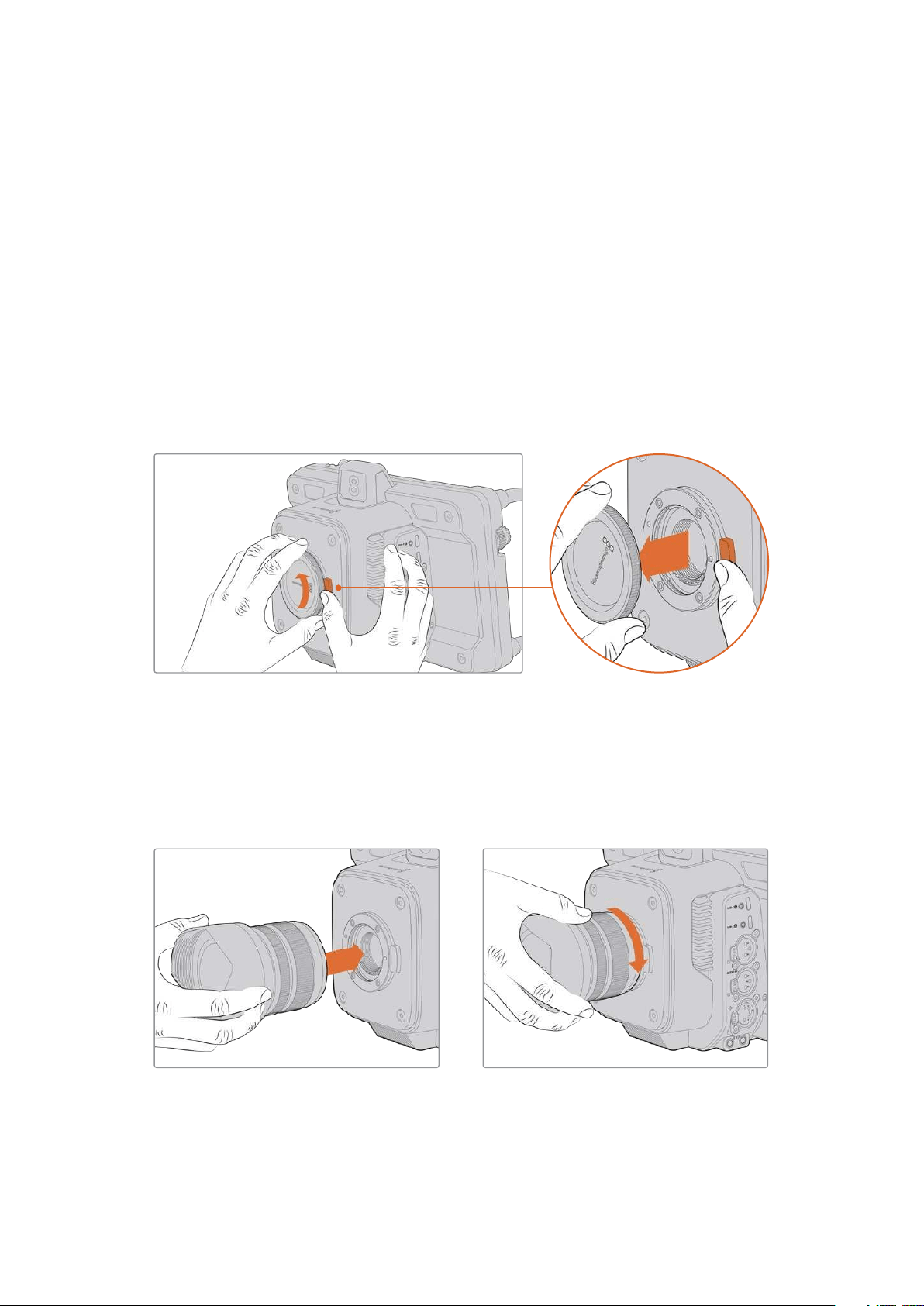
To attach a lens:
1 Align the dot on your lens with the dot on the camera mount. Many lenses have
acorresponding indicator which may be a colored dot or similar marker.
2 Gently push the lens’s mount flat against the camera’s lens mount and rotate the lens
clockwise until it locks into place.
Place the rear of the lens against the mount and rotate clockwise until it locks into place
To remove the lens, hold down the lens release button and rotate the lens counterclockwise
until its indicator reaches the 12 o’clock position. The lens will now be released and you can
gently remove it from the mount.
7Getting Started
NOTE It’s important to mention that when no lens is attached to the camera, the
lens mount is exposed to dust and other debris so you should keep the dust cap on
whenever possible.
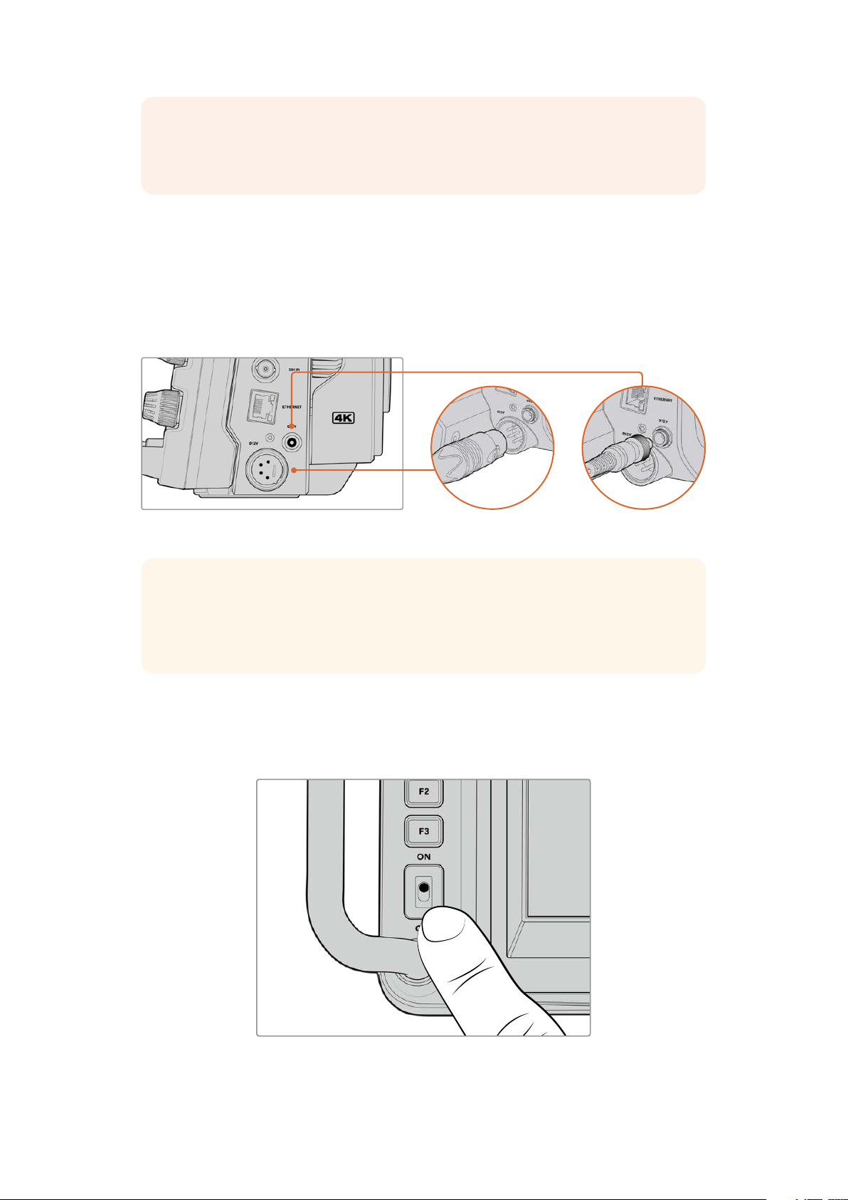
Plugging in Power
All Blackmagic Studio Cameras have 12V locking power connectors. After plugging in the
connector, secure it to the camera by tightening the locking ring.
If your studio camera has a 4 pin XLR power connector, you can plug in broadcast style power
supplies like the URSA 12V power adapter. When both power connectors are being used, the
4pin XLR input provides redundancy with the small locking connector providing primary power.
On Blackmagic Studio Camera 4K Pro and 6K Pro models, both power inputs can be connected for redundancy.
TIP Blackmagic Studio Cameras have power inputs that are rated for a voltage range
of 12-18V so you can use standard 14V batteries or 14V block batteries. Connect these
batteries to your camera using either the small barrel connector or the large 4-pin
XLRinput.
Turning Your Camera On
Switch the power button to the ‘ON’ position. The live camera image will appear on the
touchscreen and buttons will illuminate. To turn the camera off, set the switch to the ‘OFF’ position.
Set the power switch to ‘ON’ to turn on your camera
8Getting Started
Setting the Frame Rate and Resolution
With a lens attached and the camera turned on, the next step is to set the video format for the
HDMI or SDI output. This is the video standard and frame rate you will be sending to destination
equipment such as an ATEM switcher, a monitor, or HyperDeck disk recorder.
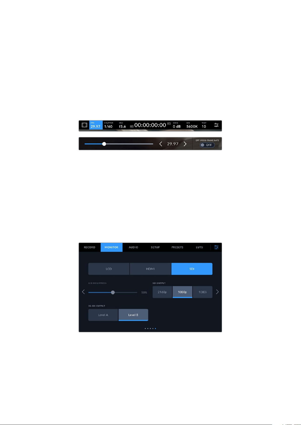
To set the frame rate:
1 Tap the frames per second icon marked FPS in the LCD status display. This will open the
frame rate settings using the touchscreen head up display.
2 Tap the arrows or drag the slider to set the frame rate.
3 Tap outside the setting to confirm and close the head up display.
To set the output standard:
1 Tap the menu settings icon at the top right corner of the touchscreen. This opens all menu
settings for your camera.
2 Tap the ‘monitor’ menu tab.
3 Tap on the right arrow to select page 5 of the monitor settings and select the HDMI or
SDI output.
4 Set the output standard by tapping 2160p for UltraHD, or 1080p for HD. On Pro models you
can also select 1080i for the SDI output if you have set a frame rate of 50p, 59.94p or 60p.
If you are connected to an ATEM switcher via HDMI, your camera’s HDMI connector will
automatically detect if the standard should be 1080p and set it accordingly.
The monitor settings let you set the video standard for the SDI or HDMI output
9
Getting Started
NOTE When recording Blackmagic RAW to a USB-C flash disk connected to Studio
Camera 4K Plus or 4K Pro G2 the recording standard is always Ultra HD. This means
you can still record a full resolution Ultra HD master even if you are sending your
switcher an HD feed.
On Blackmagic Studio Camera 6K Pro you can choose to record in Ultra HD, 5.3K or
6K resolutions. For more information refer to the ‘record settings’ section.
Connecting to an ATEM switcher
Connecting to an ATEM switcher lets you switch multiple studio cameras in your live production
and control them using the switcher or ATEM Software Control. Tally signals are sent back to
your camera so your camera’s tally light illuminates when it is switched on air.
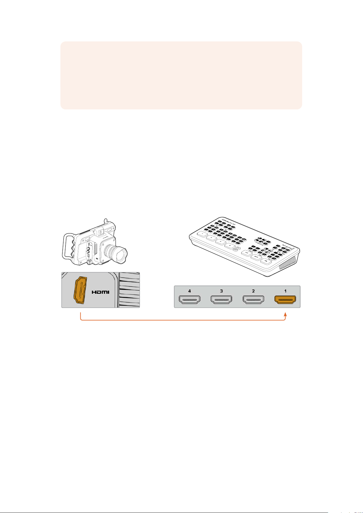
Connecting via HDMI
Plug your Blackmagic Studio Camera’s HDMI output into the corresponding HDMI input on the
ATEM switcher, such as ATEM Mini Pro ISO. We recommend matching your cameras with their
corresponding input number. For example, camera 1 to input 1 and camera 2 to input 2.
SDI IN
SDI OUT
ETHERNET
+
12V
+
12V
ATEM Mini Pro ISOBlackmagic
Studio Camera 4K Pro
When connected via HDMI, all tally and camera control data is sent back to your camera using
the same HDMI cable.
10Getting Started
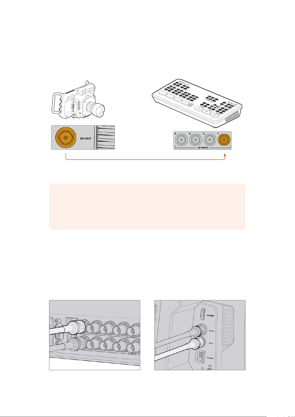
Connecting via SDI
Plug your Blackmagic Studio Camera’s SDI output into the corresponding SDI input on the
ATEM switcher, for example ATEM SDI Pro ISO.
SDI IN
SDI OUT
ETHERNET
+
12V
+
12V
ATEM SDI Pro ISOBlackmagic
Studio Camera 4K Pro
When connected via SDI, the tally and camera control data is sent back to your camera using
aseparate SDI program return feed.
NOTE On ATEM Television Studio HD and ATEM Television Studio HD Pro model
switchers that have both HDMI and SDI inputs, the first SDI input is actually input
5, so you may need to set your studio camera ID to 5 for tally to work when input 5
is selected on the switcher. More information on changing the ATEM camera ID is
provided later in this section.
Connecting the Program Return Feed
The program return feed lets you monitor the program output from your switcher on your studio
camera’s LCD. The program output also contains tally, talkback, camera control data, plus
timecode and reference genlock signals.
To connect the program return feed, connect any of the ATEM switcher’s SDI outputs to your
studio camera’s SDI input. If there is not enough program outputs, you can use any of the
auxiliary outputs. Some ATEM switchers have extra program outputs to help ensure you have
enough outputs for multiple cameras. On ATEM switchers such as ATEM Constellation 8K,
program return can be set to any of the switcher’s outputs.
Connect the switcher’s SDI output to your camera’s SDI input
11Getting Started
You can also use a Blackmagic Mini Converter SDI Distribution to feed the program output to
more cameras.
NOTE All outputs carry camera control data except for the multiview and any down
converted outputs.
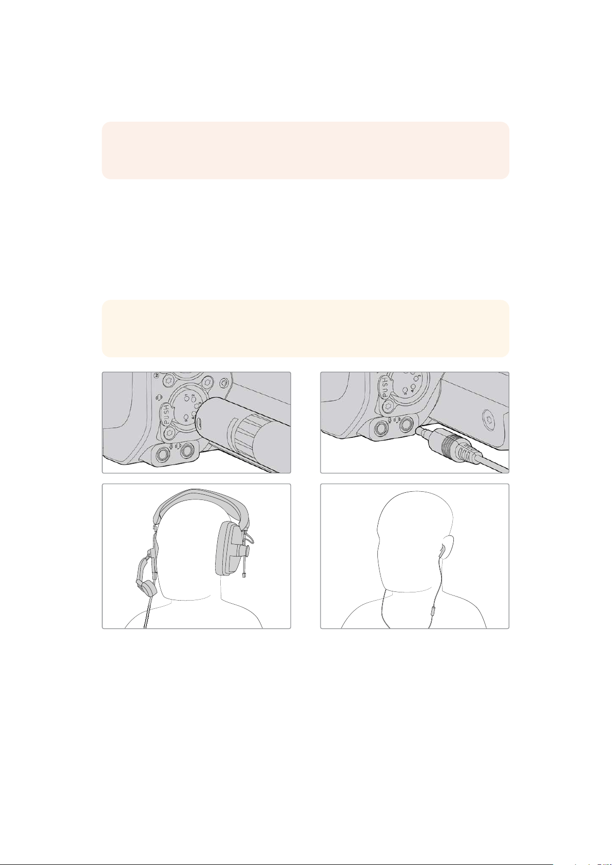
Connecting a Talkback Headset
Plug a broadcast headset into the 5 pin XLR talkback connector on Blackmagic Studio Camera
4K Pro, 4K Pro G2 and 6K Pro. Consumer headsets that are commonly used on smartphones
can also be used via the 3.5mm headset connector.
Connecting talkback lets you communicate with the switcher operator. Talkback audio is
embedded into channels 15 and 16 of the SDI signal.
TIP The plus model does not have talkback, but you can listen to your camera audio
by plugging a headset into the 3.5mm headphone socket.
You can use common 3.5mm TRRS phone headsets that have a built in microphone via the 3.5mm jack,
or use a5 pin XLR talkback headset on Blackmagic Studio Camera 4K Pro and 6K Pro models
12
Getting Started
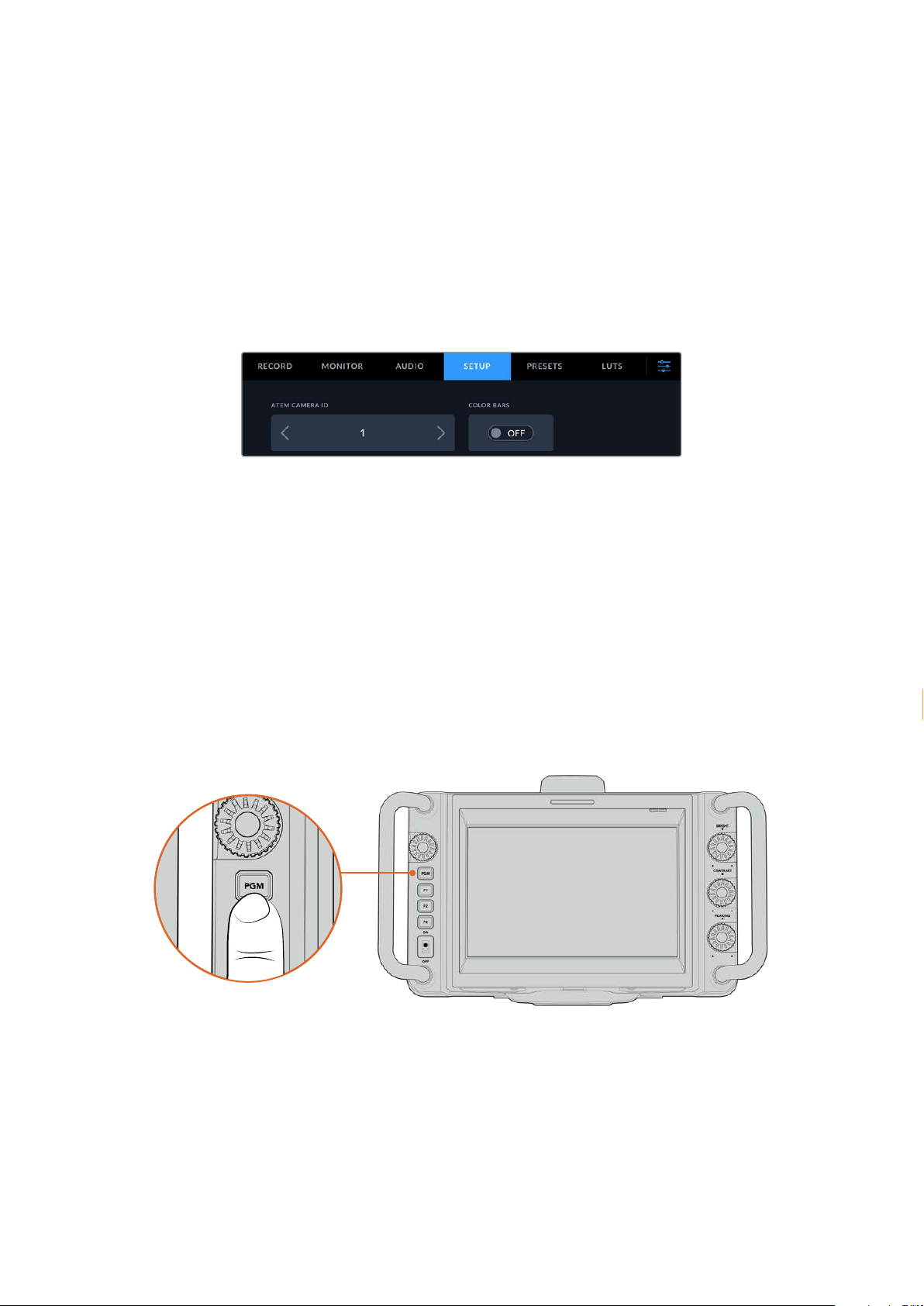
Setting the ATEM Camera ID
The ATEM camera ID is a setting in your camera’s menu settings that determines which
SDI input your studio camera is connected to on the ATEM switcher. When the camera ID
corresponds to the switcher’s input number, your camera will detect tally data for that input and
the tally light will work correctly on your camera.
When connected to an ATEM switcher via HDMI, you don’t need to worry about setting the
camera ID as the switcher can detect the input each camera is connected to and assign tally
data accordingly.
For more information on changing the ATEM camera ID, refer to the ‘menu settings’ section.
Change the ATEM camera ID using your studio camera’s ‘setup’ settings
Checking your Setup
Now that everything is plugged in and ATEM Camera IDs are correct, you can check that your
program return and tally are working.
Testing Program Return
On studio cameras that have a program return feed connected, press and hold the program
button marked PGM on your camera, then switch color bars to the program output on your
ATEM switcher. If you see color bars on your camera, you know the program output is working
properly with your camera.
You can also lock the program view on the screen by double pressing the button. Press again
to return to your camera’s live image.
Press and hold the program button marked PGM to monitor the switcher’s program output
13Getting Started
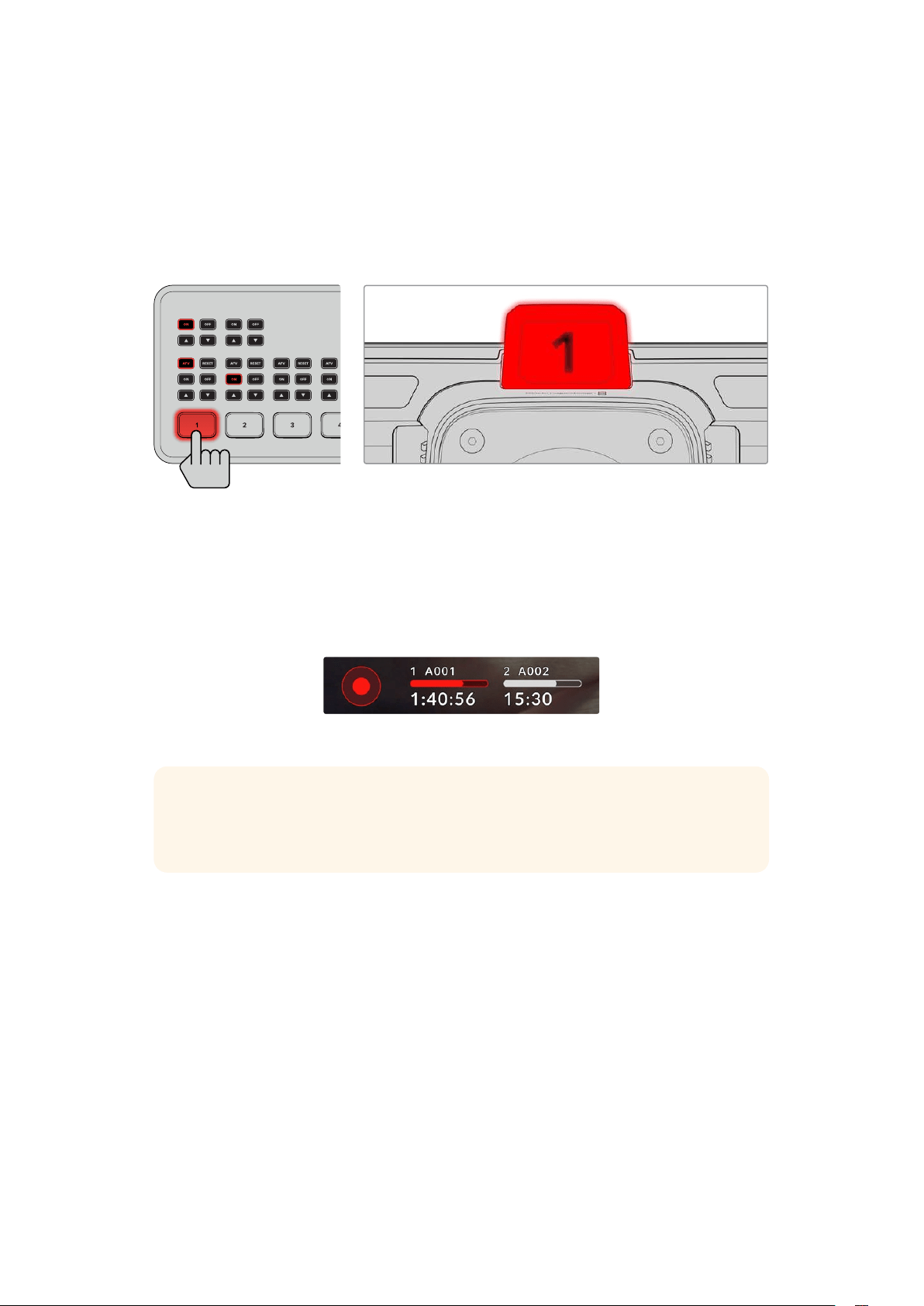
Testing Tally
All studio camera models have a built in tally light so you can check that tally is working. To
do this, switch camera 1 to the program output. The tally light on your studio camera should
now illuminate. If not, double check your ATEM camera ID is set to the corresponding input on
the switcher.
Your camera is now successfully connected to the ATEM switcher.
MIC 1 MIC 2
ATEM Mini Pro ISO
When your studio camera is switched to the program output, the tally light will illuminate
Recording Blackmagic RAW to USB
Finally, if you want to record to Blackmagic RAW on your camera, all you need to do is plug a
USB-C flash disk formatted to Mac OS Extended or exFAT into your camera’s USB connector
and tap the record button on the touchscreen! Press again to stop recording.
When recording, the record button illuminates red
TIP When connected to ATEM Mini or ATEM SDI Extreme and Pro model switchers,
you can simultaneously trigger record in all cameras from ATEM Software Control.
Formore information, refer to the ATEM Mini or ATEM SDI manual.
That’s all there is to getting started! Keep reading this manual for more comprehensive
information about all the controls and settings on your Blackmagic Studio Camera.
14Getting Started
Studio Camera Connectors
This section contains details about all the connectors on Blackmagic Studio Cameras.
Theavailable connectors will differ based on the model you are using.
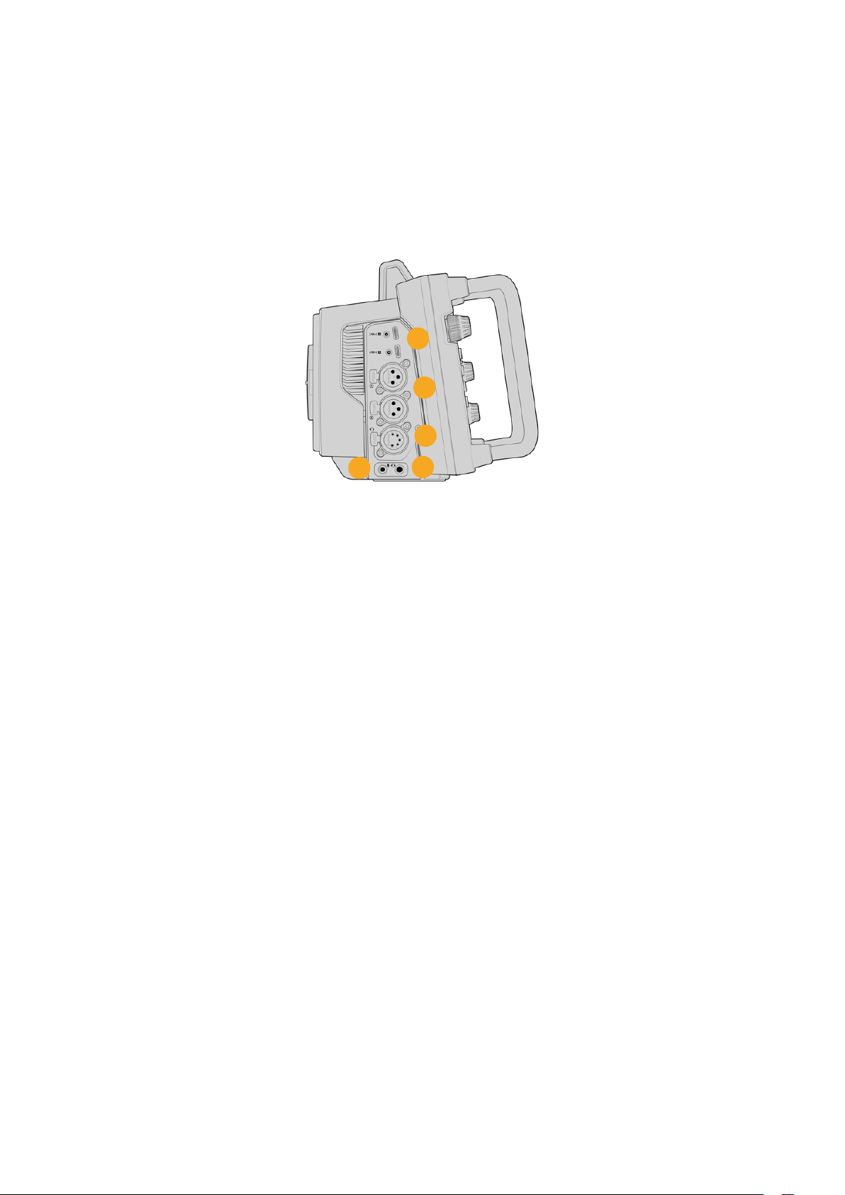
Left Panel
1
5
2
3
4
1 Locking USB
The two USB-C expansion ports allow for direct local recording onto USB-C flash disks and
can be used for connecting Blackmagic Zoom and Focus Demands. Port A is also used for
updating the camera’s internal software.
On Blackmagic Studio Camera 6K Pro and 4K Pro G2, you can connect a smartphone to
one of your camera’s USB ports and stream directly to the internet using your smartphone’s
4G or 5G cellular connection. For more information, refer to the ‘streaming video’ section
later in this manual.
2 3.5mm Microphone Jack
Connect a microphone to your camera’s 3.5mm stereo connector. Mic and line level
audio are supported. The microphone level audio is lower than the line level, so if you
are connecting a microphone to the camera and have line level selected, you will find the
levels are too low. The microphone input also accepts SMPTE compliant LTC timecode from
an external source on the left channel. Valid timecode will be detected automatically, and
embedded in your video file as timecode metadata. We recommend sending LTC timecode
via a line level output, especially if you are not recording timecode as an audio track.
3 3.5mm Headphone Jack
Monitor audio by plugging headphones into the 3.5mm stereo headphones jack.
4 XLR Audio In
Use the two balanced XLR inputs to plug in external analog audio from professional
equipment such as audio mixers, PA systems or external microphones. The XLR connectors
supply 48V phantom power so you can use microphones that aren’t self powered. Refer to
the ‘settings’ section for more information on phantom power.
5 5-Pin XLR Talkback
Plug a broadcast headset into the 5 pin XLR connector. Using a broadcast headset lets you
communicate with the switcher operator. A pinout diagram is provided later inthis section.
15Studio Camera Connectors
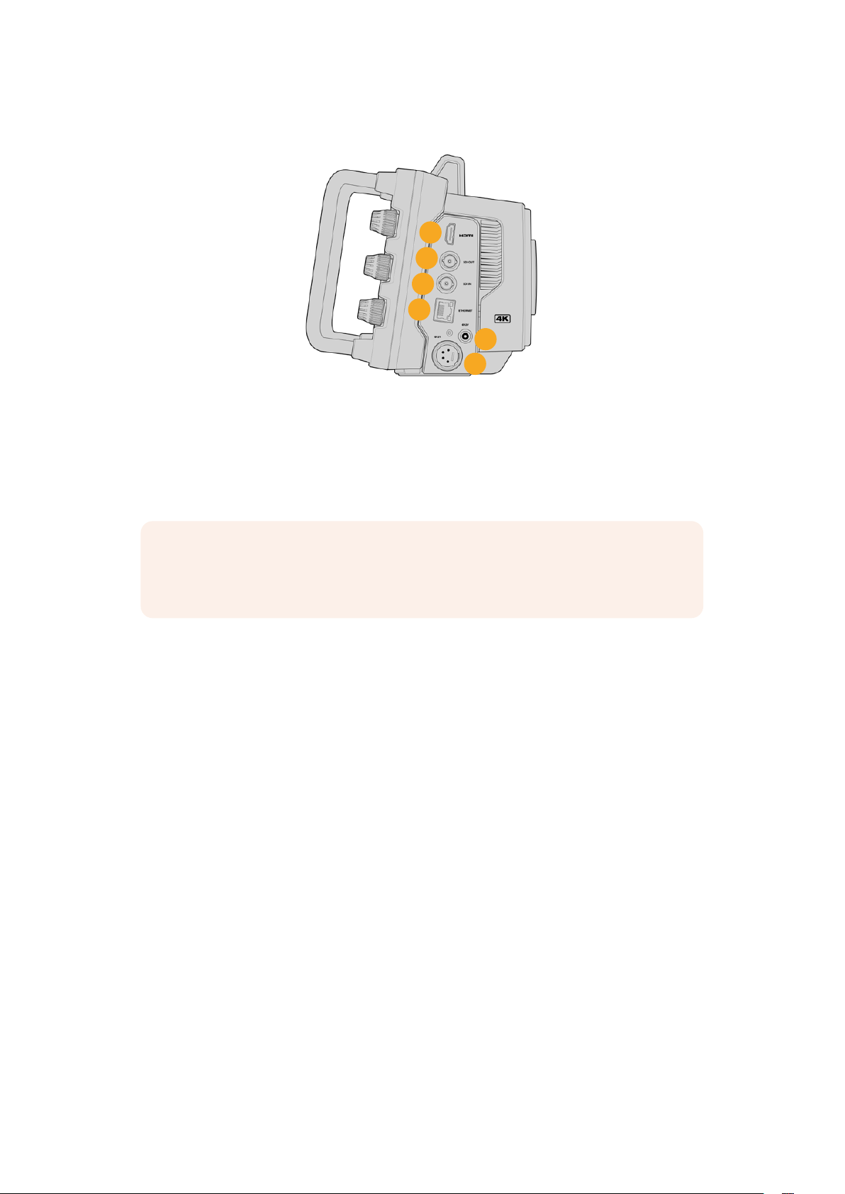
Right Panel
6
7
9
10
11
8
6 HDMI Output
The full size HDMI connector supports 10-bit 4:2:2 2160p Ultra HD video up to 60 frames
per second with support for two channels of embedded audio. Use the touchscreen menu
to set a clean feed or include overlays on the output.
You can use the HDMI port to connect to an external monitor, disk recorder or ATEM
switcher. HDMI 2.0 cables are recommended if outputting Ultra HD footage.
NOTE When connecting via HDMI to an ATEM Mini switcher, your camera’s HDMI
output standard will be automatically set to HD. This also applies when connecting to
HD equipment such as HD monitors and HD HyperDeck disk recorders.
7 SDI Out
Use the 12G-SDI output to connect to professional SDI video equipment such as an ATEM
switcher or HyperDeck disk recorder.
8 SDI In
Use the 12G-SDI input to connect the program return feed from an SDI switcher.
9 Ethernet PoE
For studio camera models with a 10G Ethernet port, you can power your camera via PoE.
Topower the camera through this port, an advanced high power PoE power supply such
asthe Blackmagic Studio Converter or a PoE type 4 power supply is required.
The Ethernet port on Blackmagic Studio Camera 6K Pro and 4K Pro G2 can also be used to
stream video over a network or the internet. Refer to the ‘streaming video’ section for more
information about how to stream video using your camera’s 10G Ethernet connector.
10 Locking Power Input
The 12-18 Volt DC locking power connector accepts the AC power supply that is provided
with your camera. The locking ring prevents accidental disconnection. You can also use this
connector to plug in a battery power supply if AC power is not available.
11 4 pin XLR Power Input
Use the 12 to 18 Volt 4 pin male XLR connector for plugging in a redundant power supply
from external sources such as the URSA 4 pin AC to 12V DC power supply or portable
batteries.
16Studio Camera Connectors
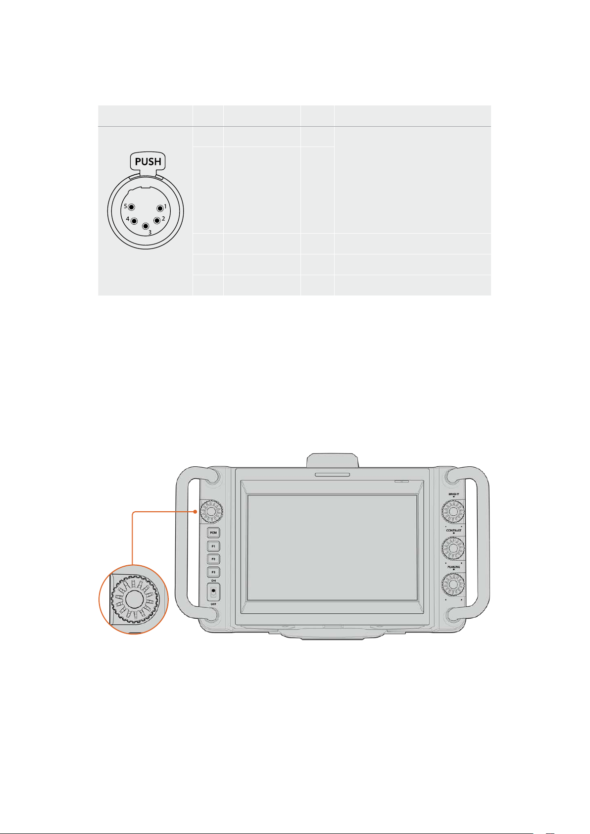
5 Pin XLR Talkback Connector Pinout Diagram
External views Pins Signal I/O Description
5 pin XLR
‘headset’ connector
1 Intercom MIC (Y) In - The intercom mic input supports
dynamic mics, which can be balanced
or unbalanced. Pin 1 is the mic signal
common, and pin 2 is the mic signal
input for both types. With electret
mics, an external DC bias supply
adapter is required which allows for
aviation headsets to be used.
2 Intercom MIC (X) In +
3 GND GND GND
4 Intercom left Out
5 Intercom right Out
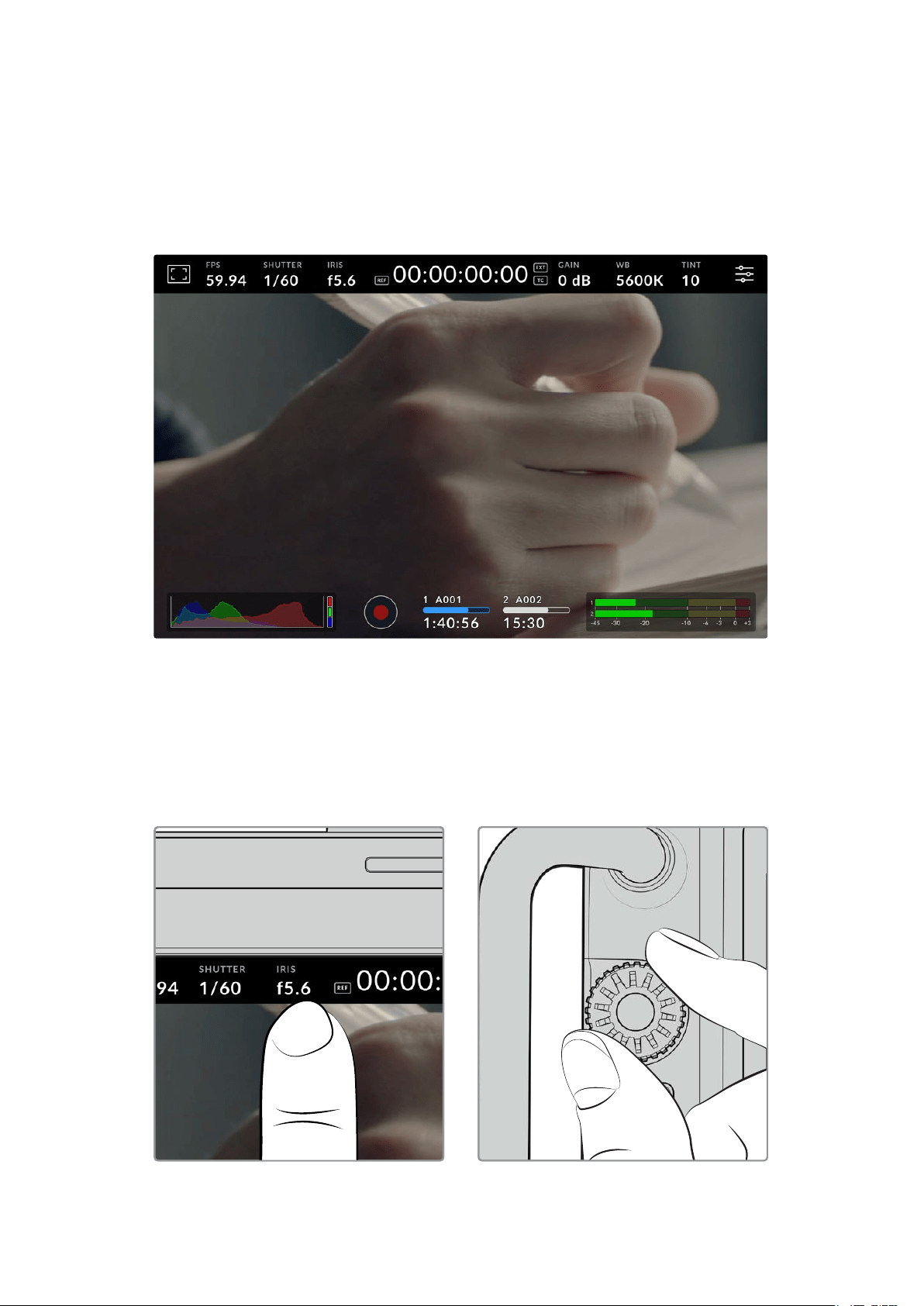
Using Studio Camera Controls
Your Blackmagic Studio Camera features a large, bright 7” LCD touchscreen so you can monitor
the live image, plus change settings directly from the LCD. Simply press the onscreen menu
button to access the menus and change settings using tap and swipe gestures.
Dials on the right side let you change screen brightness and contrast as well as focus peaking
sensitivity.
The settings dial on the left side lets you adjust the aperture on compatible micro four thirds
lenses, plus change settings and adjust parameters in combination with the head up display.
Settings Dial
Rotate the dial counterclockwise to open the iris and clockwise to close. Press the settings dial
to quickly access your camera’s menu settings.
The settings dial is also used to adjust white balance, shutter speed and gain settings when
they are selected on the camera’s head up display.
When the ‘focus zoom’ function is enabled, the image is magnified for you to see greater detail.
Rotate the settings dial to reposition the cropped image.
17Using Studio Camera Controls
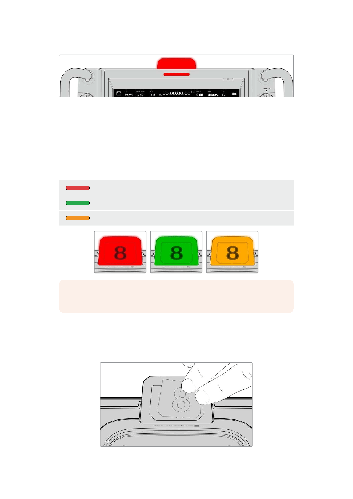
Tally Light
Your studio camera has a small tally indicator on the LCD, plus a large tally light on the top
panel. When your camera is connected to an ATEM switcher, the tally light lets the talent and
camera operator know which camera is on air, which camera is about to go live and if the
camera is recording.
When your camera is on air, the tally indicators illuminate red, green when switched to the
preview output and orange when ISO recording.
Your camera also features clip-on transparent camera numbers that attach to the tally light,
making it easy for talent to see camera numbers up to 20 feet away.
Camera is switched to the program output and is live on air.
Camera is switched to the preview output and about to go on air.
Recording to a USB-C flash disk.
NOTE When the camera is not connected to a switcher the tally light will illuminate red
as a simple record tally indicator.
Tally Light Number Template
Editable PDF’s are provided in the software installer allowing you to edit and print out your own
custom tally numbers to match ones provided. After installing the Blackmagic cameras software
these can be found on a Mac in the Application > Blackmagic Cameras > Documents folder and
on aPC in the Blackmagic Design > Documents folder.
Tally light numbers can be easily changed
18Using Studio Camera Controls
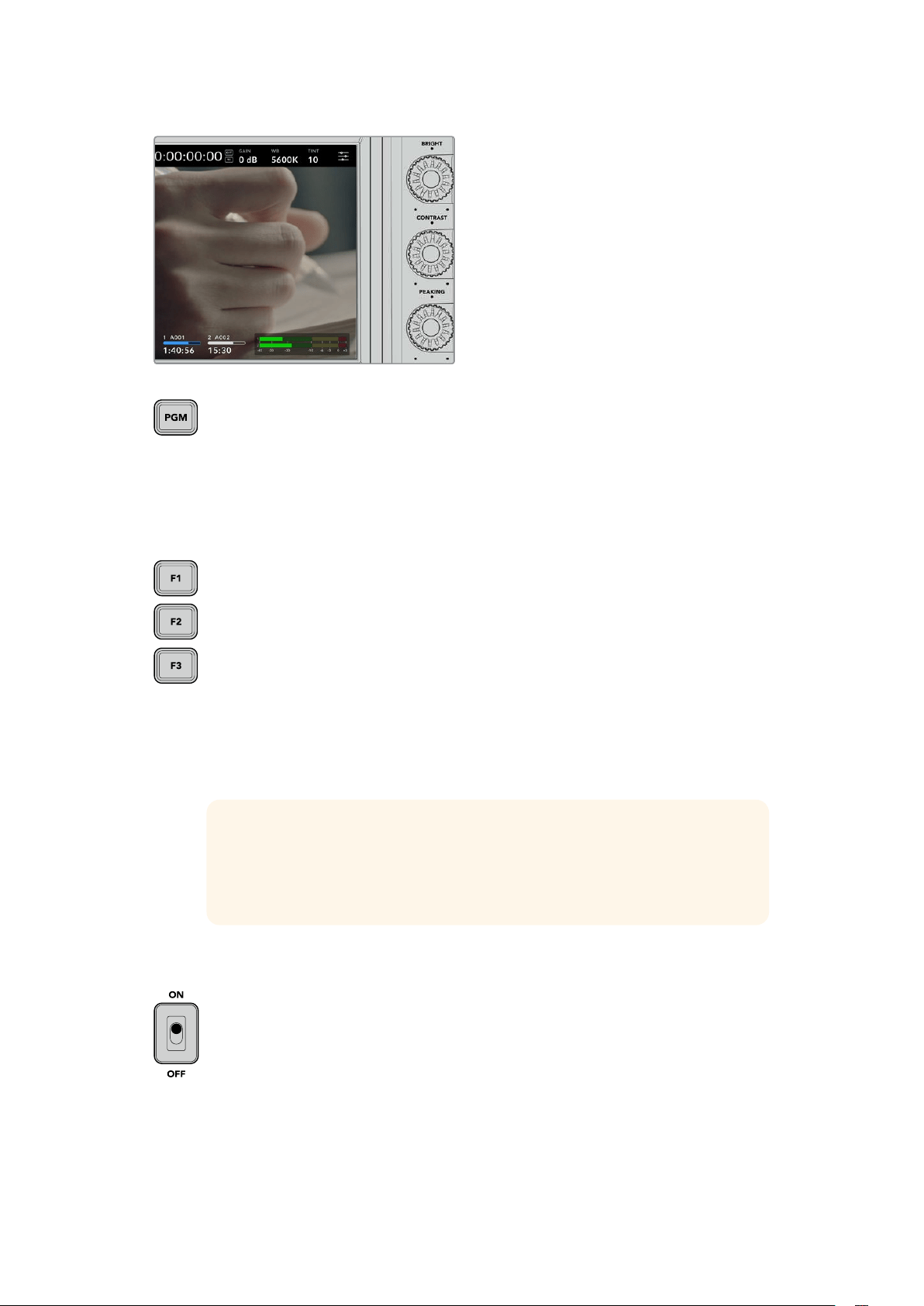
Bright, Contrast and Peaking
Use these three dials to adjust the
brightness, contrast and focus peaking
levelon the LCD touchscreen.
You can use a traditional focus peaking
style, plus the option to use colored lines
with red, green, blue, black or white lines.
Touchscreen Display
Monitor the image using the built in
touchscreen. Tap and swipe to zoom
andadjust settings.
Back/PGM Button
When connected to an ATEM Switcher, pressing and holding the ‘program’ button
displays the return feed on the LCD. Releasing the button returns you to your live
camera image. Double press the PGM button to lock on the program return feed.
Pressagain to return to your live camera image.
On Blackmagic Studio Camera 4K Plus, this button is labeled ‘back’. Press the back
button to close the menu settings and return the LCD to the live image.
Function Buttons
These are assignable buttons you can set for easy access to your most commonly
usedfunctions. The default functions for these buttons are:
F1 – Focus zoom.
F2 – Focus. Triggers auto focus on compatible lenses.
F3 – Iris. Triggers auto iris with compatible micro four thirds lenses on Blackmagic
Studio Camera 4K Plus and 4KPro models.
On Blackmagic Studio Camera 6K Pro use the F3 button to cycle through the built in
neutral density filters. See ‘ND Filters on Blackmagic Studio Camera 6K Pro’ for more
information.
TIP The ND filters on Blackmagic Studio Camera 6K Pro can be adjusted
remotely via ATEM Software Control, ATEM Camera Control Panel or an ATEM
Television Studio switcher. You can also adjust your camera’s ND filters from
one of the function buttons on Blackmagic Zoom Demand.
For more information on assigning the function buttons, refer to the ‘setup settings’
chapter in the ‘menu settings’ section.
ON/OFF switch
Switches the camera on and off.
19Using Studio Camera Controls
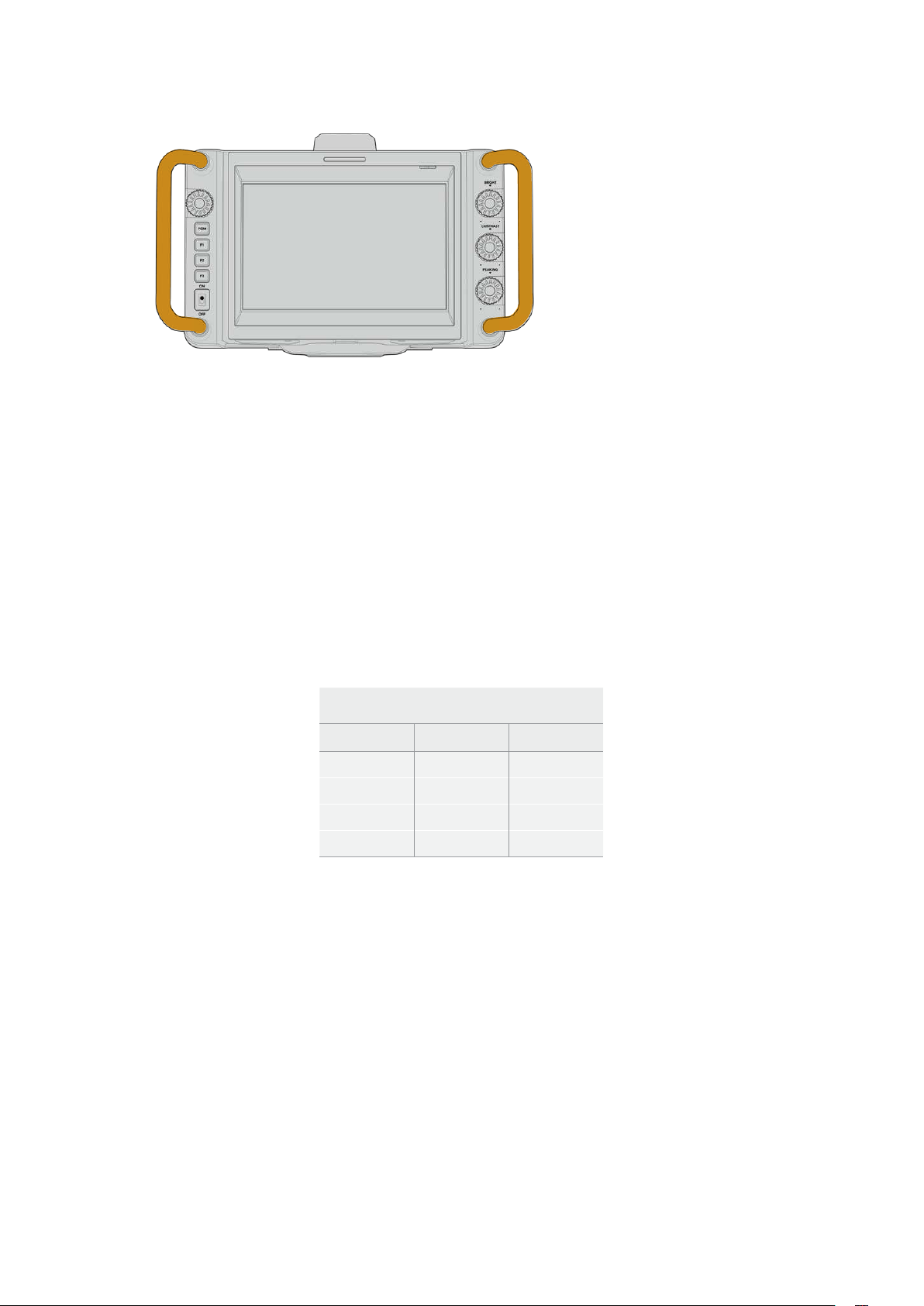
Handles
Built in handles on each side
of your camera let you hold
the camera when carrying and
setting up. They also help protect
the screen when setting up and
packing down.
Using the ND Filters
Blackmagic Studio Camera 6K Pro has three internal neutral density filters. Together with a
clear filter, the available settings are 1/4, 1/16th and 1/64th. These filters allow you to reduce
the amount of light reaching your camera’s sensor by a preset fraction. With more control over
exposure, you can be more selective with your aperture to optimize your lens’s sharpness and
image quality.
The ‘clear’ setting means there is no ND filter being used. From settings 1/4 to 1/64th, the ND
filters gradually increase in density so you can decrease light if you need to.
General terms for ND filters can vary, so the measurement of your ND settings can be
customized in the LCD touchscreen menu. You can identify the ND filter number, amount of
stops in light reduction, or the fraction representing the amount of light reduced for the filters
tosuit your preference. For more information, refer to the ‘setup settings’ section.
Neutral Density Filter Settings
ND number Stops Fraction
clear 0 1
0.6 2 1/4
1.2 4 1/16
1.8 6 1/64
The function buttons on your camera can be assigned to control the ND filters. For example,
setF1 to ‘ND up’ to step up to a higher ND filtration and set F2 to ‘ND down’ to change to a
lower filtration. Alternatively, you could set one function button to ND up or ND down to cycle
through the filters using just one button if you need to use F1 and F2 for other functions. Use
the setup settings in your camera’s LCD menu to assign controls to the function buttons.
Refer to the ‘menu settings’ section for more information.
20Using the ND Filters
Storage Media
Your Blackmagic Studio Camera features two high speed USB-C expansion ports that allows
you to record video directly to USB-C flash disks.
USB-C Flash Disks
USB-C flash disks are fast, high capacity drives that can record video for long periods. This can
be important when filming events with long durations. You can connect two USB-C flash disks
to your Blackmagic Studio Camera at the same time.
When recording has ended, you can then connect the USB-C flash disk directly to your
computer for editing and post production without having to copy media across.
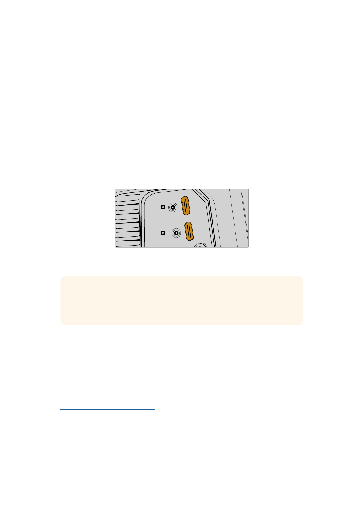
To connect a USB-C flash disk to your camera:
1 Plug a USB-C cable into your USB-C flash disk.
2 Plug the other end of the cable into the ‘A’ or ‘B’ USB-C port on your camera.
USB-C
USB-C
The USB-C flash disk will occupy the corresponding media slot on your camera’s LCD
touchscreen.
TIP If you have two USB-C disks connected, your camera will automatically start
recording to the second disk when the first disk is full. Prior to recording, you can
choose which one your camera records to by pressing and holding on the storage
indicator on the LCD touchscreen.
Choosing a fast USB-C flash disk
USB-C flash disks are designed to offer fast, affordable storage for a wide range of devices and
are readily available from a variety of consumer electronics outlets. It’s important to note that
film making is only one part of the USB-C flash disk market, so choosing the best drive is vital to
making sure you have enough speed to record 6K and 4K footage.
Many USB-C flash disks are designed for home computing and aren’t fast enough to record 6K
and 4K video.
For the most up to date list of recommended USB-C flash disks please go to
www.blackmagicdesign.com/support.
21Storage Media

Important Notes About USB-C flash disk Speed
Some models of USB-C flash disk can’t save video data at the speed the manufacturer
claims. This is due to the disk using hidden data compression to attain higher write
speeds. This data compression can only save data at the manufacturer’s claimed speed
when storing data such as blank data or simple files. Video data includes video noise
and pixels which are more random so compression will not help, therefore revealing the
true speed of the disk.
Some USB-C flash disks can have as much as 50% less write speed than the
manufacturer’s claimed speed. So even though the disk specifications claim a USB-C
flash disk has speeds fast enough to handle video, in reality the disk isn’t fast enough
for real time video capture.
Use Blackmagic Disk Speed Test to accurately measure whether your USB-C flash
disk will be able to handle high data rate video capture and playback. Blackmagic Disk
Speed Test uses data to simulate the storage of video so you get results similar to what
you’ll see when capturing video to a disk. During Blackmagic testing, we have found
newer, larger models of USB-C flash disk and larger capacity USB-C flash disks are
generally faster.
Blackmagic Disk Speed Test is available from the Mac app store. Windows and Mac
versions are also included in Blackmagic Desktop Video, which you can download
from the ‘capture and playback’ section of the Blackmagic Design support center at
www.blackmagicdesign.com/support.
Preparing USB-C Flash Disks for Recording
You can format USB-C flash disks using the ‘format’ feature on your camera’s storage and
formatting menu, or via a Mac or Windows computer. For best performance, we recommend
formatting USB-C flash disks using your camera.
HFS+ is also known as Mac OS Extended and is the recommended format as it supports
‘journaling’. Data on journaled media is more likely to be recovered in the rare event that your
storage media becomes corrupted. HFS+ is natively supported by Mac. exFAT is supported
natively by Mac and Windows without needing any additional software, but does not support
journaling.
Preparing Media on Blackmagic Studio Camera
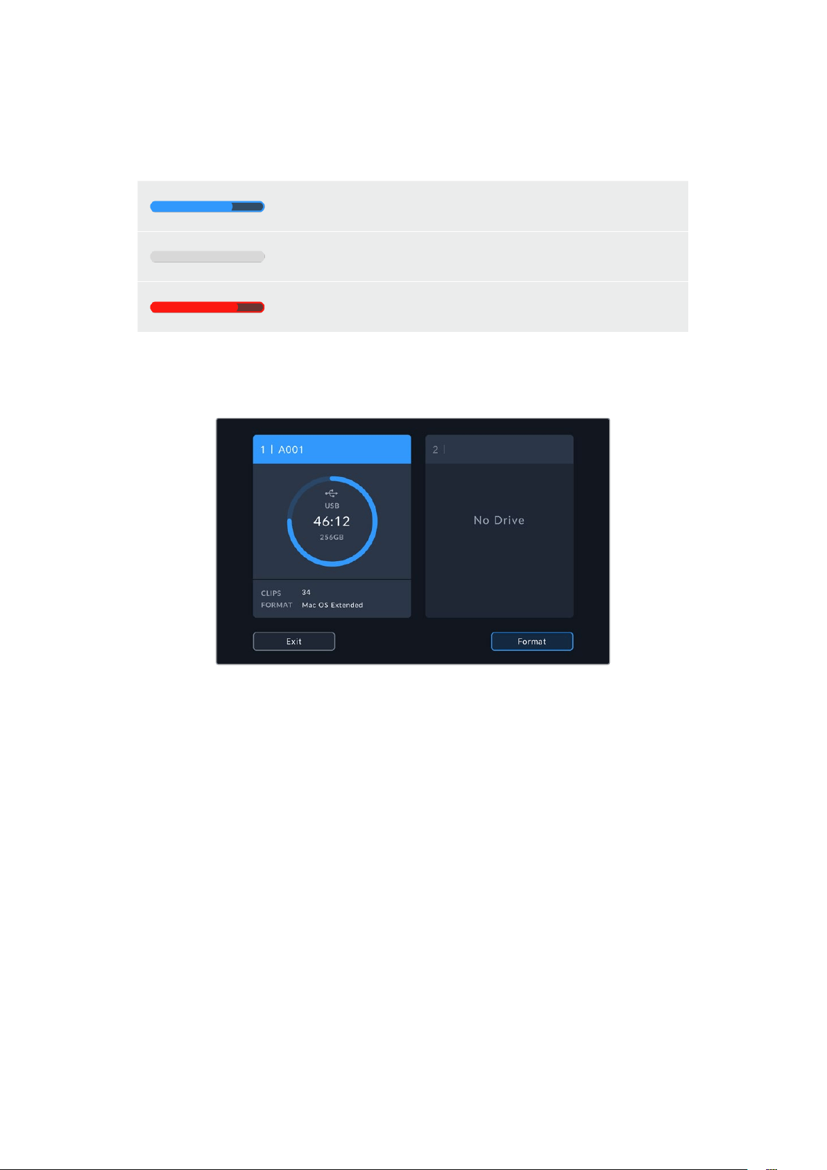
1 Tap either storage indicator at the bottom of the LCD touchscreen to open the
storage manager.
2 Tap the ‘format’ button at the bottom of the screen.
22Storage Media
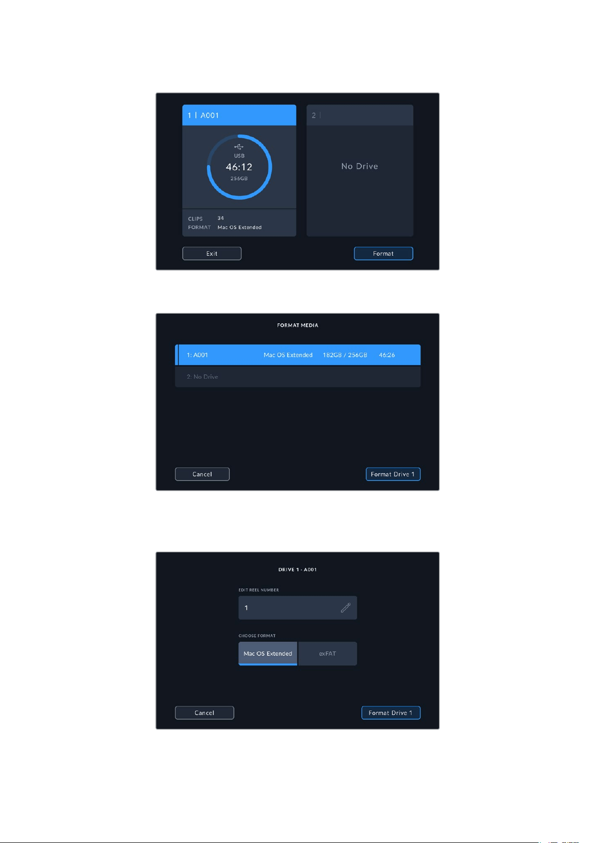
3 In the ‘format media’ menu, select the drive that you want to format and tap the
‘formatdrive’ button at the bottom of the screen.
4 Tap ‘edit reel number’ if you would like to manually change the reel number. Use the
keypad to enter a new reel number and press ‘update’ to confirm your selection.
5 Choose OS X Extended or exFAT format and tap the ‘format drive’ button.
6 A confirmation screen will allow you to confirm the drive to be formatted, the selected
format type and the reel number. Confirm your selection by tapping the ‘format drive’
button. Tap ‘cancel’ to cancel the format.
23Storage Media
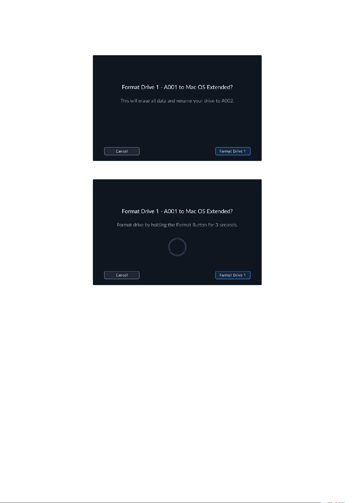
7 Hold down the ‘format drive’ button for three seconds to format your media.
8 The camera notifies you when the format is complete and your drive is ready for use.
Tap‘ok’ to return to the storage manager.
When formatting USB-C flash disks using your camera, the camera ID that is generated from
the slate and reel number are used to name the media. Your camera automatically adjusts
the reel numbers incrementally each time you format. If you need to manually enter a specific
reel number, tap the ‘edit reel number’ and enter the number you want to format the card as.
When you start a new project, reel numbering will reset to 1 when you tap on ‘reset data’ in the
‘project’ tab of the slate.
Preparing Media on a Mac
The Disk Utility application included with the Mac operating system can format your USB-C
flash disks in the HFS+ and exFAT formats.
Make sure you back up anything important from your media as all data will be lost when it
isformatted.
To format your disk:
1 Connect the USB-C flash disk to your computer and dismiss any message offering to use
your media for Time Machine backups.
2 Go to applications/utilities and launch Disk Utility.
3 Click on the disk icon for your USB-C flask disk and then click the ‘erase’ tab.
24Storage Media
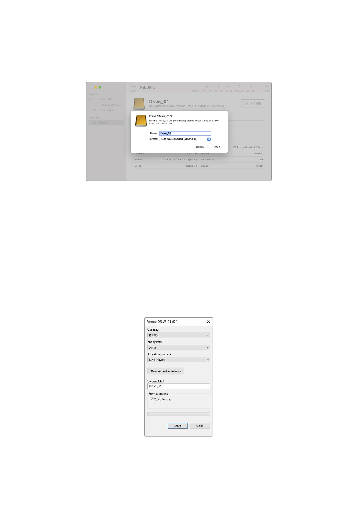
4 Set the ‘format’ to ‘Mac OS extended ( journaled)’ or ‘exFAT’.
5 Type a ‘name’ for the new volume and then click ‘erase’. Your USB-C flash disk will quickly
be formatted and made ready for use with your camera.
Preparing Media on a Windows PC
Windows PCs provide a ‘format’ option when you right click on the drive. Make sure you back
up anything important from your USB-C flash disk as you will lose everything on it when it is
formatted.
To format your disk:
1 Connect a USB-C flash disk to your computer.
2 Open the start menu or start screen and choose computer. Right-click on your USB-C
flash disk.
3 From the contextual menu, choose ‘format’.
4 Set the file system to exFAT and the allocation unit size to 128 kilobytes.
5 Type a volume label, select ‘quick format’ and click ‘start’.
6 Your media will quickly be formatted and made ready for use with your camera.
Use the ‘format’ dialog box feature
in Windows to format your camera’s
storage media in the exFAT format
25
Storage Media
Touchscreen Controls
Your Blackmagic Studio Camera’s LCD touchscreen features a tap and swipe gesture based
interface. By tapping and swiping on the status display and icons, you can quickly open the
head up display and access the camera’s settings while shooting.
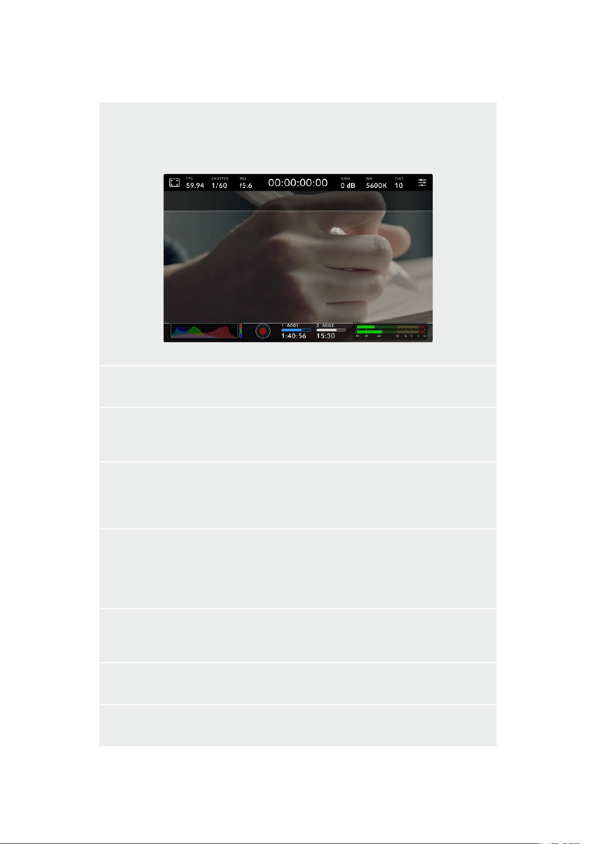
Your studio camera’s LCD touchscreen lets you monitor the image and change settings
Changing Settings using the Head up Display
The head up display is a quick settings menu you can open and change by tapping on a setting.
Simply tap on an item to open the head up display, then make changes using the touchscreen
or rotating the settings dial. After making your selection, tap the screen to quickly close the
selection menu.
Tap a setting on the touchscreen and make a change by turning the settings dial
26
Touchscreen Controls
Touchscreen Features
This section of the manual describes the settings you can change using the head up display
and settings dial.
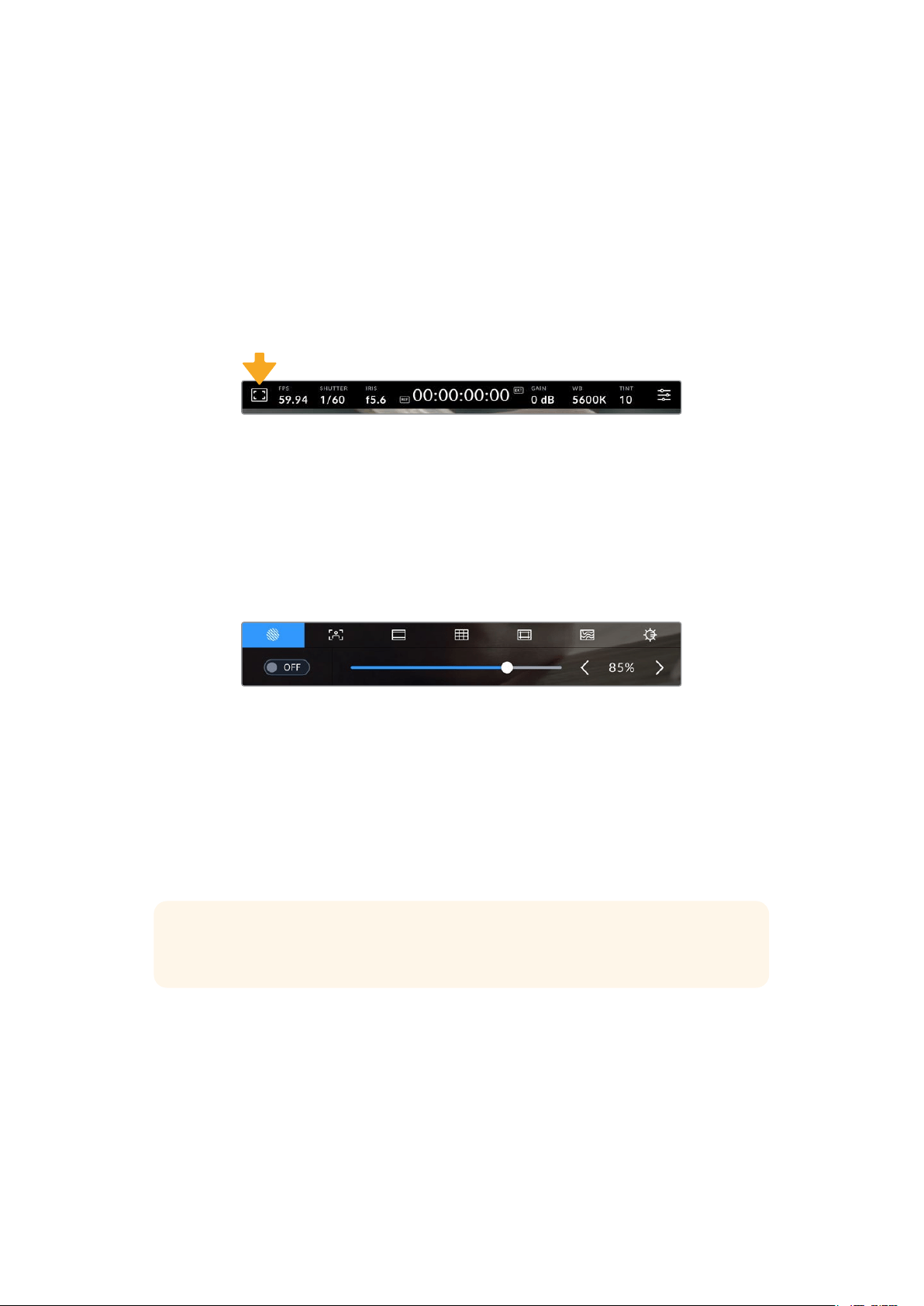
LCD Monitor Options
Tap the ‘monitor’ icon at the top left of the touchscreen to access the LCD monitor settings.
These settings let you toggle and adjust the appearance of your studio camera’s monitoring
features, including zebra, focus assist, frame guides, grids, safe area guides and false color.
When accessing LCD monitor options, the controls for these features appear in a tabbed menu
along the bottom edge of the LCD touchscreen.
Tap the icon at the top left of your camera’s LCD touchscreen to access LCD
monitor options
Zebra
The ‘zebra’ setting toggles the appearance of the zebra on the LCD touchscreen, as well as
setting the zebra level.
Zebra displays diagonal lines over areas of your image that exceed a set exposure level. For
example, setting zebra to 100% shows which areas are completely overexposed. This is useful
for achieving optimum exposure in fixed lighting conditions.
Tap the ‘zebra’ icon while accessing ‘LCD monitor options’ to access the zebra settings
To toggle the zebra for the LCD touchscreen, tap the switch icon in the bottom left of the screen
while in the ‘zebra’ tab.
Set the exposure level at which the zebra appears by dragging the slider left and right, or
tapping the arrow buttons next to the zebra level percentage. Zebra level is adjustable in five
percent steps between 75 and 100 percent exposure.
For information on enabling zebra on your camera’s HDMI or SDI output, see the ‘monitor
settings’ section in this manual.
TIP If you’re shooting in variable light such as outdoors on a partly overcast day,
setting your zebra level lower than 100 can warn you of potential overexposure.
27Touchscreen Controls
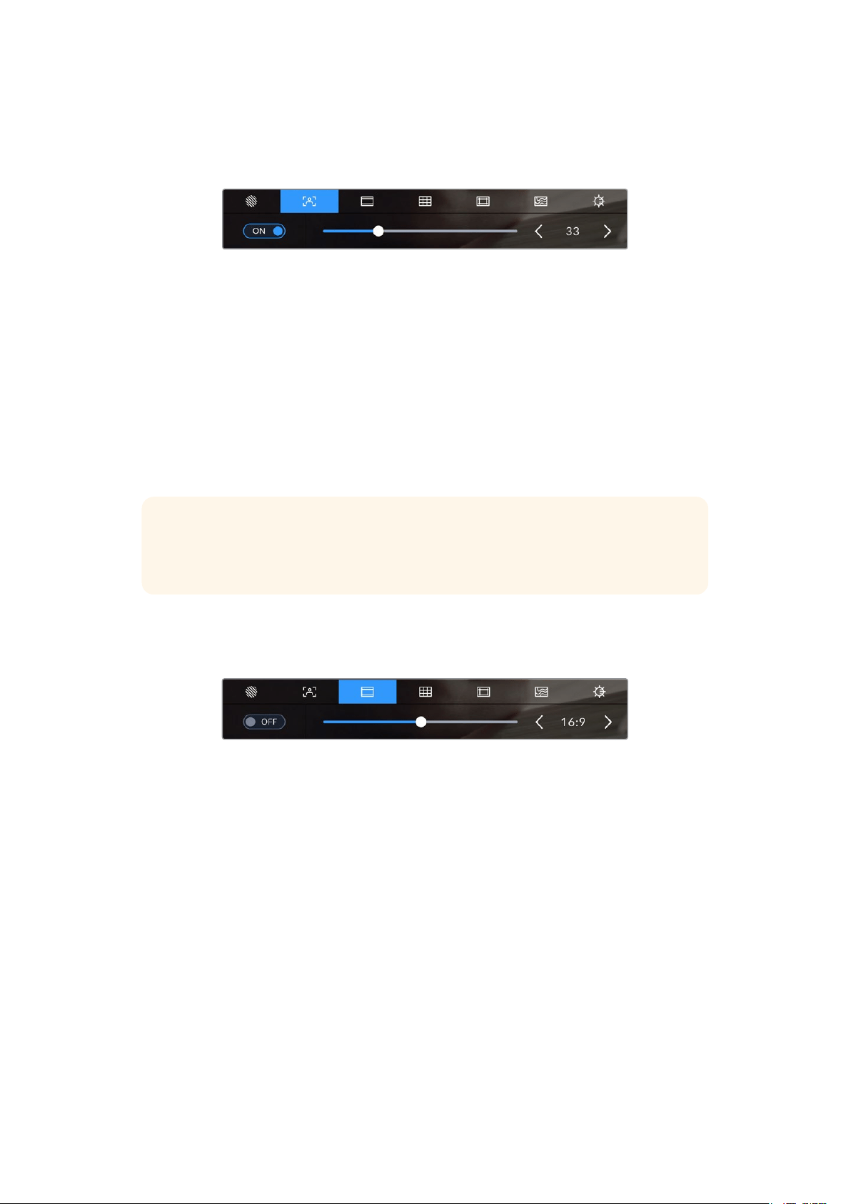
Focus Assist
The ‘focus assist’ setting toggles the appearance of focus assist on the LCD touchscreen,
aswell as setting the level of focus assistance for all outputs on your studio camera.
Tap the ‘focus assist’ icon while accessing ‘LCD monitor options’ to access your
camera’s focus assist settings
To toggle focus assistance for the LCD touchscreen, tap the switch icon in the bottom left
ofthescreen while in the ‘focus assist’ tab. To set the level of focus assistance move the slider
leftand right along the bottom of the touchscreen.
The optimum level of focus assistance varies shot by shot. When focusing on actors, for
example, higher level of focus assistance can help resolve edge detail in faces. A shot of
foliage or brickwork, on the other hand, may show distracting amounts of focus information
athigher settings.
For information on enabling focus assist on your camera’s HDMI or SDI output, see the
‘monitorsettings’ section in this manual.
TIP Your Blackmagic Studio Camera has two focus assist modes. You can switch
between ‘peaking’ and ‘colored lines’ focus assistance in the ‘monitor’ settings menu.
For more information, see the ‘monitor settings’ section in this manual.
Frame Guides
The ‘frame guide’ setting toggles the appearance of frame guides on the LCD touchscreen.
Frame guides include aspect ratios for various cinema, television and online standards.
Tap the ‘frame guides’ icon while accessing ‘LCD monitor options’ to access your
frame guide settings
To toggle the appearance of frame guides on the LCD touchscreen, tap the switch icon in the
bottom left of the screen.
Choose the frame guide you want to use by dragging the slider left and right, or tapping the
arrow buttons on either side of the currently selected aspect ratio. You can also enter a custom
frame guide ratio by tapping on the ratio between the arrow buttons.
28Touchscreen Controls
The available guides are:
2.35:1, 2.39:1 and 2.40:1
Displays the broad widescreen aspect ratio compatible with anamorphic or flat widescreen cinema
presentation. The three widescreen settings differ slightly based on the changing cinema standards
over time. 2.39:1 is one of the most prominent standards in use today.
The LCD touchscreen with 2.40:1 frame guides enabled
2:1
Displays a ratio slightly wider than 16:9 but not as wide as 2.35:1.
1.85:1
Displays another common flat widescreen cinema aspect ratio. This ratio is slightly wider than HDTV
1.78:1 but not as wide as 2.39:1.
16:9
Displays a 1.78:1 aspect ratio compatible with 16:9 HD television and computer screens. This ratio is
most commonly used for HD broadcasting and online videos. The same aspect ratio has also been
adopted for Ultra HD broadcasting.
14:9
Displays a 14:9 aspect ratio used by some television broadcasters as a compromise between 16:9 and
4:3 television sets. Ideally, both 16:9 and 4:3 footage remains legible when center cropped to fit 14:9.
You can use this as a compositional guide if you know your project may be broadcast by a television
station that uses 14:9 cropping.
4:3
Displays the 4:3 aspect ratio compatible with SD television screens, or to help with framing when
using 2x anamorphic adapters.
1:1
Displays a 1:1 ratio slightly narrower than 4:3. This square ratio is growing in popularity on social media.
4:5
Displays a 4:5 aspect ratio. This vertical aspect ratio is ideal for portraits and viewing on smartphones.
29Touchscreen Controls
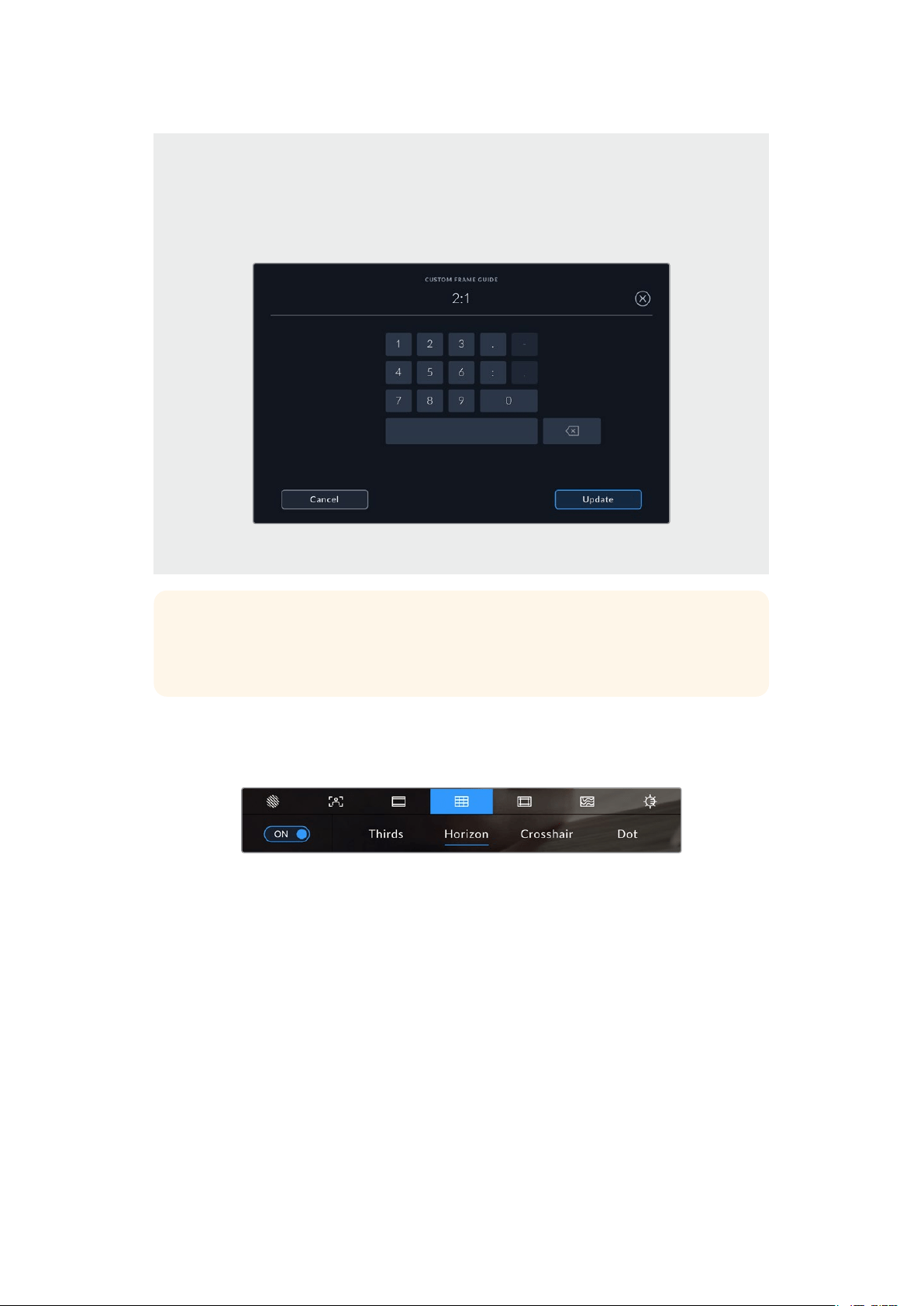
Custom Frame Guide Ratio
To create your own frame guide ratio for a unique appearance, tap on the ratio displayed between
the arrow buttons. On the ‘custom frameguide’ screen tap the backspace button to delete the current
ratio, then use the numeric keypad to specify a new ratio. Tap ‘update’ to apply your custom frame
guide ratio and return to shooting.
Use the numeric keypad on the ‘custom frame guide’ screen to enter a new
guide ratio
TIP You can change the opacity and color of frame guide overlays and enable or
disable them on your camera’s HDMI or SDI output. For more information see the
‘monitor settings’ section of this manual.
Grids
The ‘grids’ setting toggles the appearance of a rule of thirds grid, horizon meter, crosshair or
center dot.
Tap the ‘grids’ icon while accessing ‘LCD monitor options’ to access the grid settings
Grids and crosshair are overlays that can help with image composition. When ‘grids’ are
enabled, the LCD shows a rule of thirds grid, horizon, crosshair or dot.
To toggle the appearance of grids on your camera’s touchscreen, tap the switch icon in the
bottom left of the screen while in the ‘frame guides’ tab.
To set which overlay you want to display on the LCD, tap the ‘thirds’, ‘horizon’, ‘crosshair’ or ‘dot’
options. With thirds selected, you can also display either the horizon, crosshair or dot indicators.
For example thirds plus horizon, thirds plus crosshair, or thirds plus dot.
30Touchscreen Controls
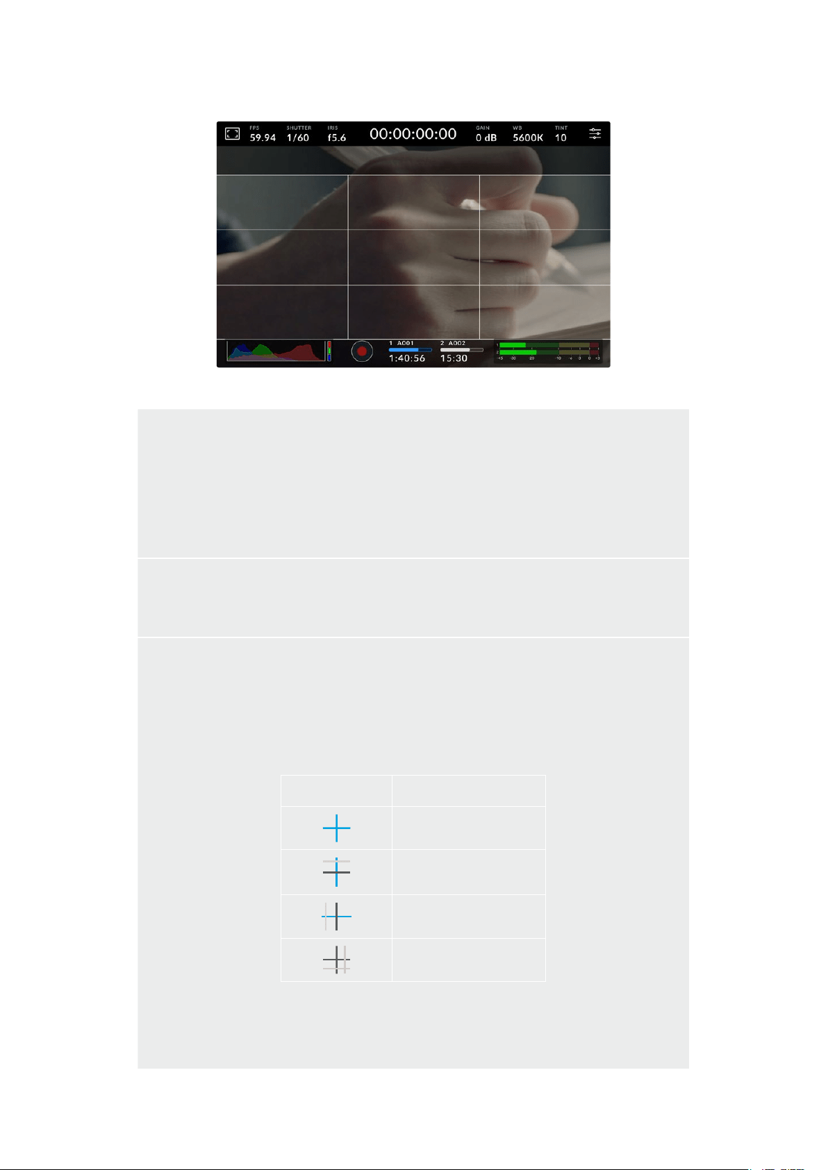
The rule of thirds grid automatically scales to any on screen frame guides
Thirds
The ‘thirds’ setting displays a grid with two vertical and horizontal lines placed in each third of the
image. Thirds are an extremely powerful tool to help compose your shots. For example, the human
eye typically looks for action near the points where the lines intersect, so it’s helpful to frame key
points of interest in these zones. An actor’s eyeline is commonly framed along the top third of
the screen, so you can use the top horizontal third to guide your framing. Thirds are also useful to
maintain framing consistency between shots.
Horizon
The ‘horizon’ meter indicates when your camera is rolled left or right and tilted up or down. Use this
meter to ensure your image always has a level horizon.
The distance the lines move away from the central crosshair is proportional to the amount of roll or tilt.
After you calibrate the camera’s motion sensor, the moving lines turn blue when aligned to their axis.
Note that if the camera is tilted straight down for an overhead shot or straight up, the horizon meter
takes this into account. If you roll the camera to shoot in portrait orientation, the horizon meter rotates
its axes 90 degrees.
This table shows examples of the horizon meter indicating tilt and roll of the camera.
Horizon meter Description
Straight and level
Tilted down and level
Straight and rolled left
Tilted up and rolled right
For normal use, calibrate the horizon meter for straight and level operation. If you want to use the
horizon meter to help maintain a consistent ‘dutch angle’ or a consistent tilt for a low or high shot,
youcan calibrate the horizon meter at an incline. For information on how to calibrate the horizon
meter, see the ‘motion sensor calibration’ section.
31Touchscreen Controls
Crosshair
‘Crosshair’ setting places a crosshair in the center of the frame. Like thirds, the crosshair is a very
useful compositional tool, making it easy to frame the subject of a shot in the very center of a frame.
This is sometimes used when filming scenes that will be assembled using fast cuts. Keeping viewers’
eyes focused on the center of a frame can make rapid editing easier to follow.
Dot
The ‘dot’ setting places a dot in the center of the frame. This works in exactly the same way as the
‘crosshair’ setting, albeit with a smaller overlay that you may find less intrusive.
NOTE For information on enabling grids on your HDMI or SDI output, see the ‘monitor
settings’ section in this manual.
Safe Area Guides
The ‘safe area guides’ setting toggles the safe area guides on or off the LCD touchscreen,
aswell as setting the size of safe area guides for your camera’s HDMI or SDI outputs.
Safe areas can be used in broadcast production so the most important parts of a shot can be
seen by viewers. By keeping the most important parts of your shot inside a central ‘safe area,’
you can avoid cropping on some televisions, as well as leaving space for a broadcaster to
add bugs, news tickers and other overlays along the edges of the screen. Many broadcasters
require footage to be submitted with important content, such as titles and graphics, contained
inside the 90% safe area.
Safe area guides can also be used to assist with framing your shot where you know that the
shot will be stabilized in post production, which can crop the edges of the image. They can also
be used to indicate a specific crop. For example by setting it to 50% when recording at Ultra
HD 3840x2160 you can see what a 1920x1080 crop of the frame would look like. The safe area
guides also scale to your frame guides, so they will adjust to indicate the chosen percentage of
your target frame.
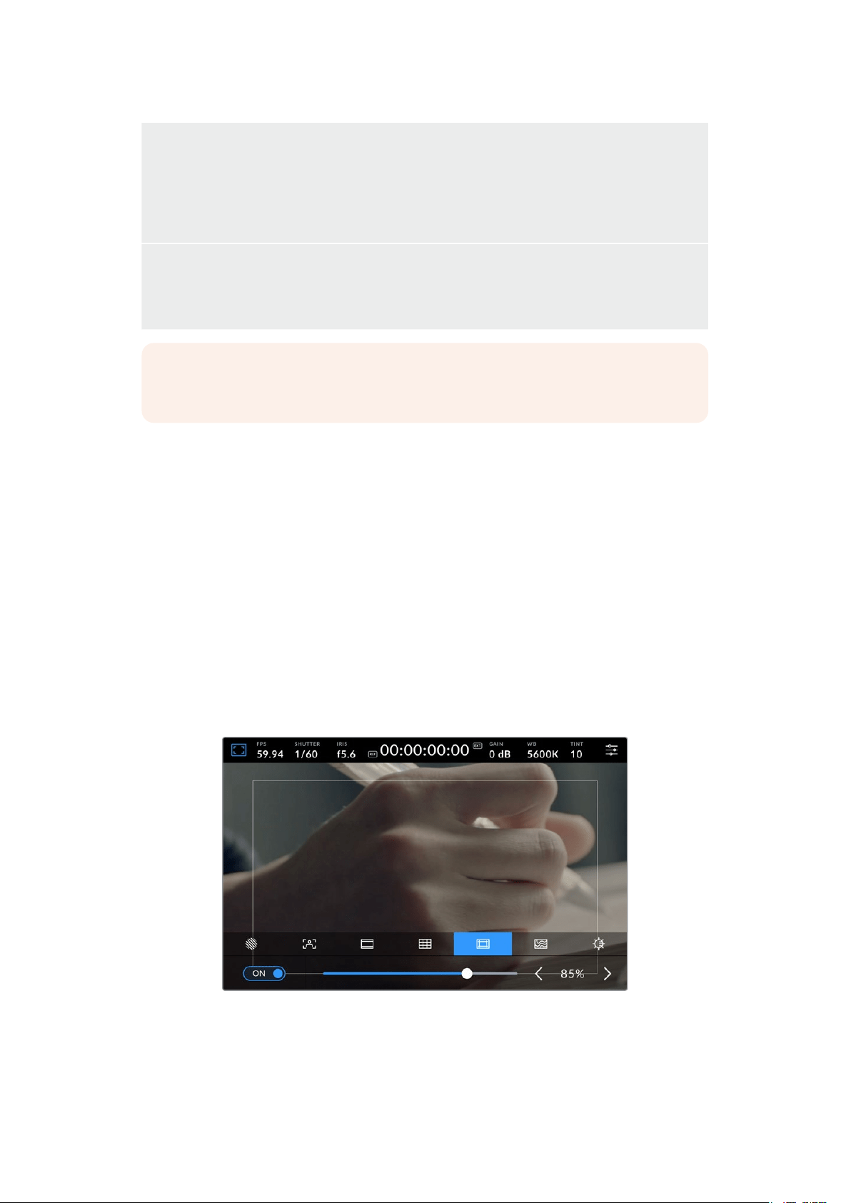
The ‘safe area’ indicator set to 85%
32
Touchscreen Controls
To toggle safe area guides for the LCD touchscreen, tap the switch icon in the bottom left of the
screen while in the ‘safe area guides’ tab. To set the level of safe area guides for your camera’s
LCD touchscreen, tap the left or right arrows on either side of the current numerical value at the
bottom of the touchscreen. Alternatively, you can drag the slider left or right.
For information on enabling safe area guides on your camera’s HDMI or SDI output, see the
‘monitor settings’ section in this manual.
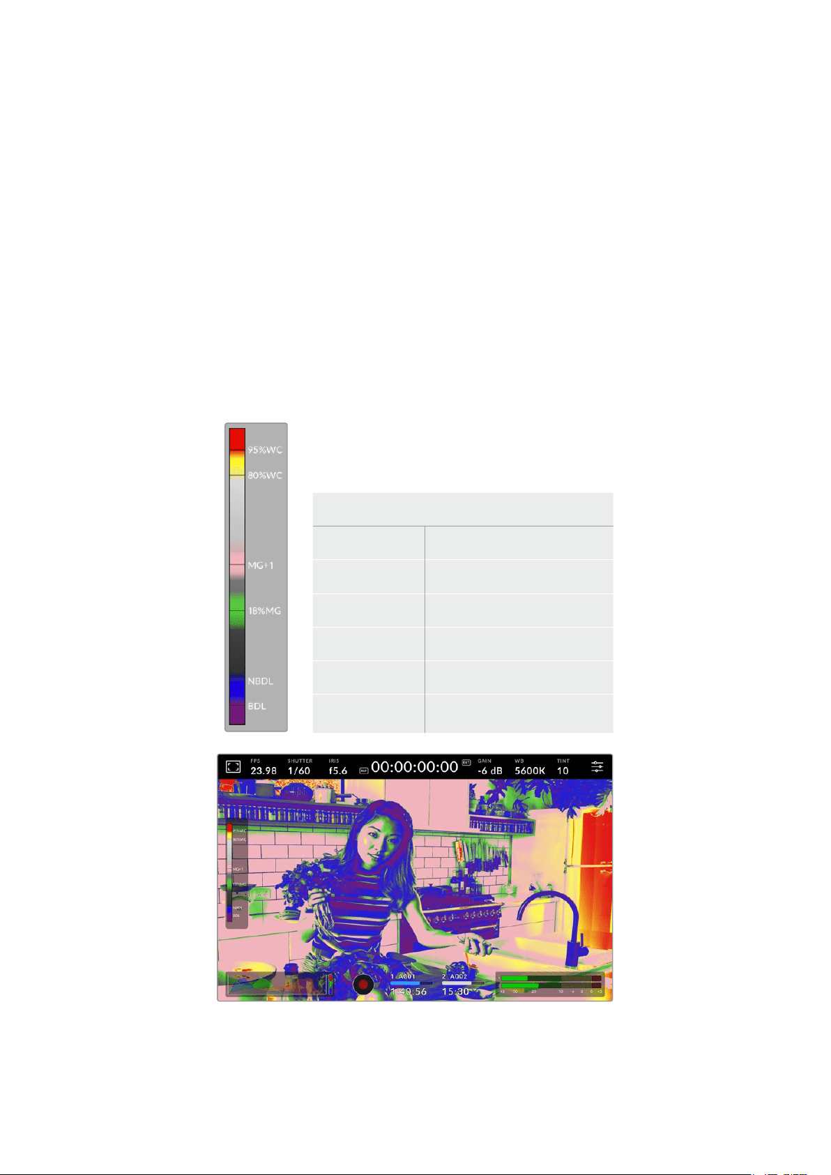
False Color
The ‘false color’ setting toggles the appearance of false color exposure assistance on the LCD
touchscreen.
False color overlays different colors onto your image that represent exposure values for
different elements in your image. For example, pink represents optimum exposure for lighter
skin tones, while green is a good match to darker skin tones. By monitoring the pink or green
false color when recording people, you can maintain consistent exposure for their skin tones.
Similarly, when elements in your image change from yellow to red, that means they are now
over exposed.
The IRE false color chart on the left side of your
camera’s display shows you how to interpret the
different false colors.
False Color Meaning
95%WC White clipping
80%WC Near white clipping
MG+1 One stop over middle gray
18%MG Middle gray
NBDL Near black detail loss
BDL Black detail loss
33Touchscreen Controls
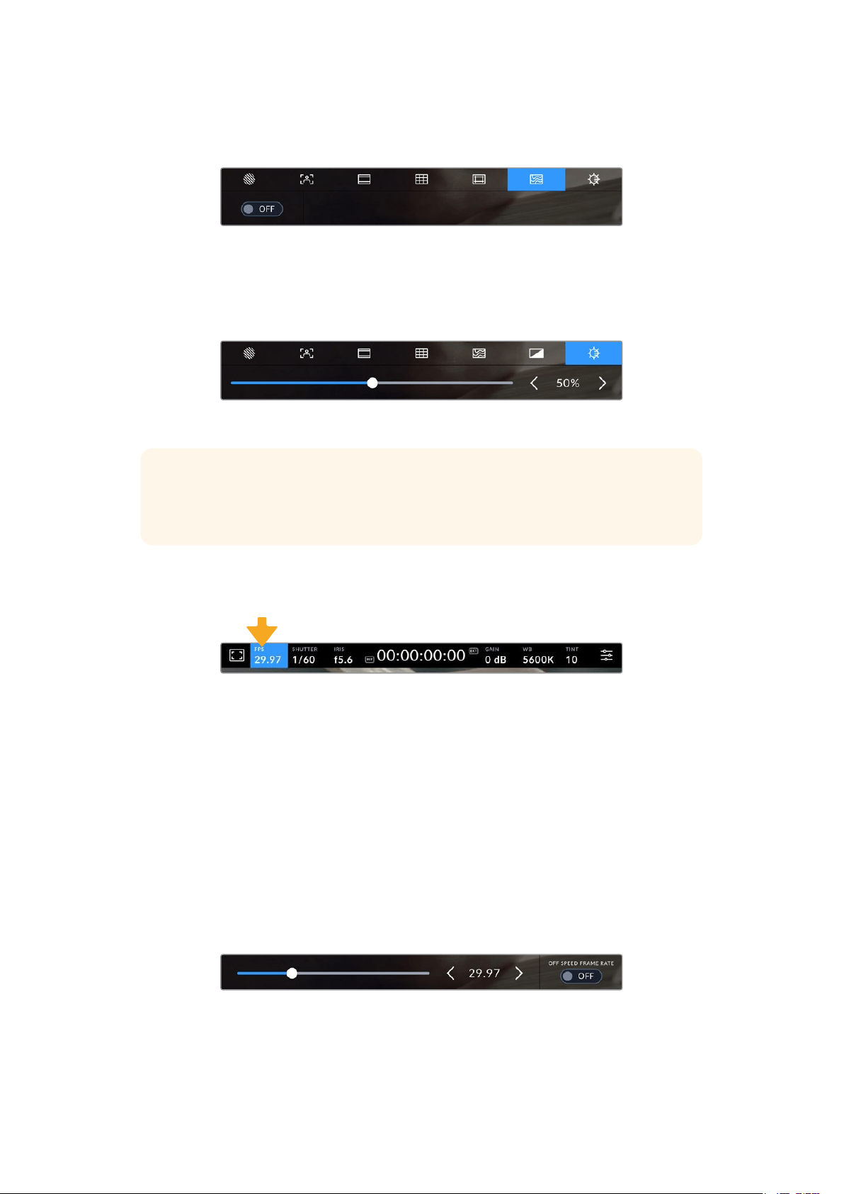
To toggle false color for the LCD touchscreen, tap the switch icon in the bottom left of the
screen while in the ‘false color’ tab.
The ‘false color’ exposure assistance tab
Screen Brightness
Tap the ‘screen brightness’ icon and drag the slider to the left or right to adjust the brightness
ofyour studio camera’s touchscreen.
The ‘screen brightness’ setting set to 50%
TIP You can also change the LCD screen brightness in the LCD tab of the
‘monitorsettings’ menu. The same screen brightness value is displayed on both
thehead up display and in the ‘monitor’ tab in the settings menu.
Frames Per Second
The ‘FPS’ indicator displays your currently selected frames per second.
Tap the frames per second indicator to access frame rate settings
Tapping the ‘FPS’ indicator lets you change your camera’s sensor and project frame rates via
amenu at the bottom of the LCD touchscreen.
Project Frame Rate
The project frame rate is the camera’s recording format frame rate and provides a selection of
common frame rates used in the film and television industry. This frame rate should normally be
set to match your broadcast delivery format.
8 project frame rates are available including 23.98, 24, 25, 29.97, 30, 50, 59.94 and 60 frames
per second.
To adjust your camera’s project frame rate while in the ‘FPS’ menu, tap the left or right arrows
next to the current frame rate at the bottom left of your touchscreen. Alternatively, you can drag
the slider left or right.
Tap the arrows on either side of the project frame rate or move the slider to
makeadjustments
34
Touchscreen Controls
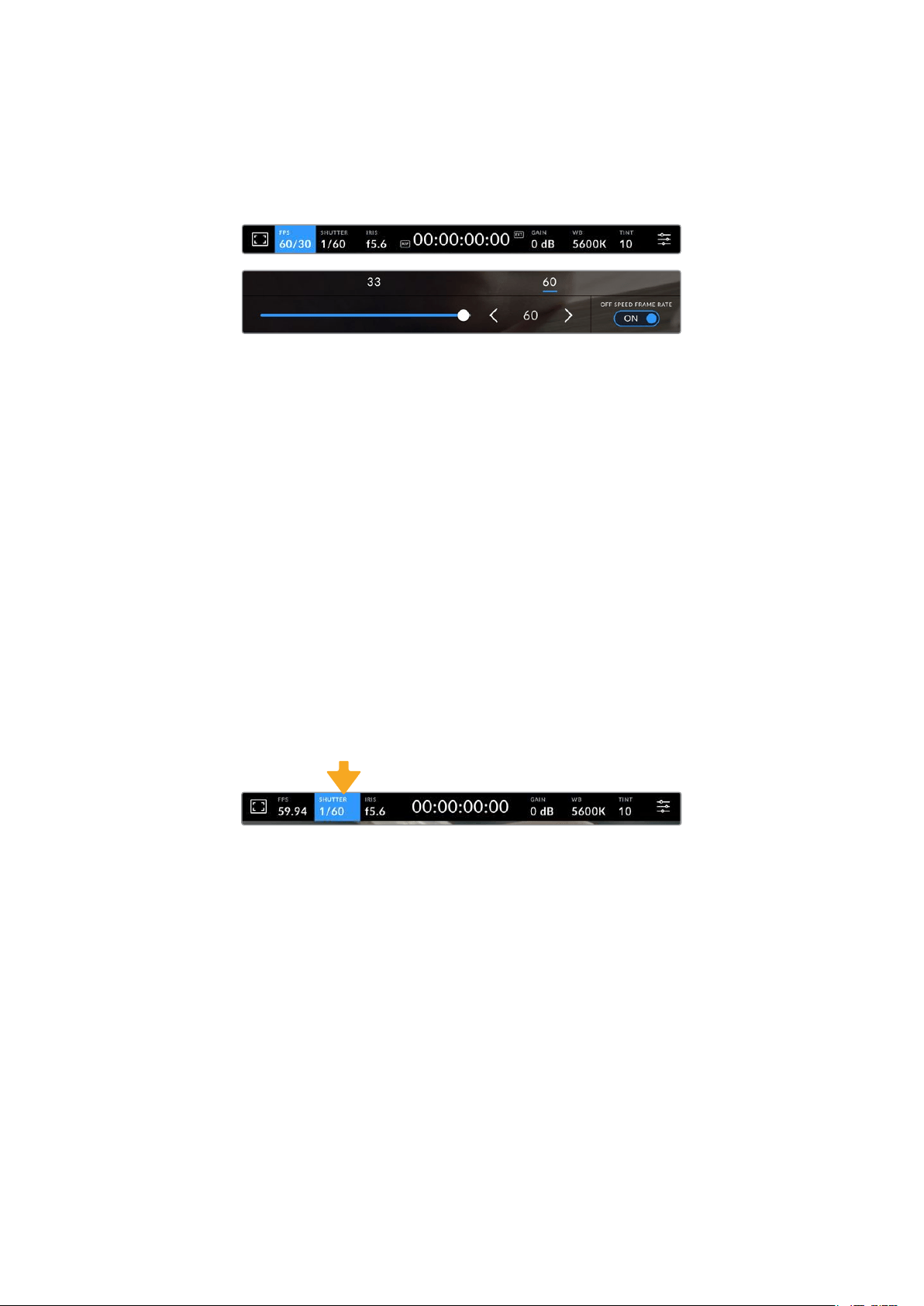
Off Speed Frame Rate
The off speed frame rate sets how many actual frames from the sensor are recorded every
second. This frame rate will affect how fast or slow your video will play back at your set project
frame rate.
With ‘off speed frame rate’ enabled, tap a preset or the arrows on either
side of the frame rate indicator or move the slider to make adjustments
By default, the project and sensor frame rates are matched for a natural playback speed.
However, by tapping the ‘off speed frame rate’ switch icon in the bottom right hand side of your
camera’s ‘FPS’ menu, you can independently set the sensor frame rate.
To change the off speed frame rate, tap the arrows next to the frame rate indicator on your
touchscreen. You can also drag the slider left or right to increase or decrease the frame rate.
Above the slider, you can tap on a common off speed frame rate. These are based on your
current project frame rate.
You can create dynamic and interesting speed effects in DaVinci Resolve by varying the off
speed frame rate for your recorded video. Setting the off speed frame rate higher than your
project frame rate will create slow motion during playback.
Shutter
The ‘shutter’ indicator displays your shutter speed or shutter angle. By tapping this indicator,
you can manually change your camera’s shutter values or configure shutter priority auto
exposure modes. The shutter measurement setting can be used to select whether to display
shutter information as ‘shutter speed’ or ‘shutter angle’. See the ‘setup settings’ section in this
manual for more information.
Tap the shutter indicator to access shutter settings
Shutter speed defines the level of motion blur in your video, and can be used to compensate
for varying light conditions. The shutter speed setting for natural motion blur, and the settings
available, depend on the frame rate you are using. For example, when shooting at 30p, a 1/60
of a second shutter speed is the equivalent of a 180 degree shutter angle, a very common
setting for film projects. However if you are shooting at 25p, you will need to set the shutter to
1/50 for the same look. As lighting conditions change, or the amount of movement in your scene
increases, you may decide to adjust accordingly.
For natural motion blur you can calculate the shutter speed by doubling your frame rate. So at
30p, set your shutter speed to 1/60 of a second for natural motion blur.
If you need more light on the sensor, you can set the shutter at the slowest setting corresponding
with your frame rate. For example, 1/25 for 25p, or 1/30 for 30p. At the slowest shutter speed,
your motion blur will appear slightly exaggerated.
35Touchscreen Controls
If you want to reduce the motion blur so action appears sharper and more defined, set the
shutter to a faster speed, such as 1/120 of a second for 30p, or 1/100 of a second for 25p. If you
are familiar with shutter angles, this equates to a shutter angle of 90 degrees.
NOTE When shooting under lights, your shutter can affect the visibility of flicker. Your
Blackmagic Studio Camera will automatically calculate a flicker free shutter value for
your current frame rate. Three suggested flicker free shutter options will appear at the
bottom of the touchscreen display when adjusting your shutter. These shutter values
are affected by mains power frequency in your region. You can set your local power
frequency to 50Hz or 60Hz in the camera’s setup menu. See the ‘setup settings’
section in this manual for more information.
Tapping the ‘shutter’ indicator brings up the suggested shutter values along the bottom of the
touchscreen. If you have auto exposure set to ‘off,’ this screen will show you your currently
selected shutter value, as well as the available flicker free shutter values, based on the
mains power frequency you have selected in your camera’s setup menu. The characteristics
of individual light sources may still cause flicker even when using flicker free values. We
recommend always performing a test shoot when not using continuous lights. For more
information, see the ‘setup settings’ section in this manual.
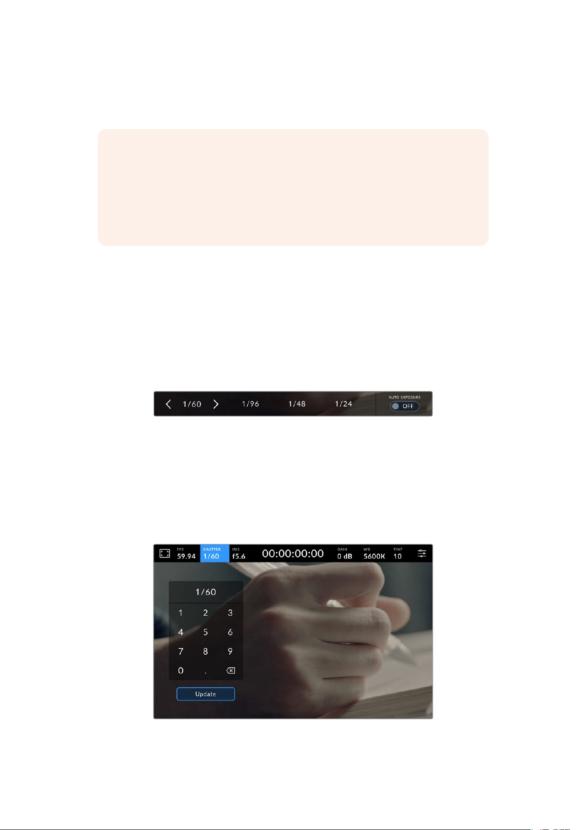
To select one of the flicker free shutter values, simply tap on one of the displayed shutter
values. Using the arrows on either side of the current shutter value indicator, will cycle through
some of the most commonly used values.
Your camera will suggest flicker free shutter values based on the mains power
frequency you choose in the ‘setup’ menu
If you would like to choose a specific shutter value, you can do so by double tapping the current
shutter indicator at the bottom left of your screen. This will bring up a keypad that allows you to
type in any shutter value you wish.
If you type in a shutter value that is less than your current frame rate, for example 1/25th when
shooting at 29.97 frames per second, the nearest achievable shutter value will be used. The
nearest shutter speed in this example would be 1/30th.
Use the manual shutter keypad to enter your shutter timing of choice when
shooting outdoors or under flicker free lights
36Touchscreen Controls
Your Blackmagic Studio Camera has three shutter based auto exposure modes. To select one
of these, tap the ‘auto exposure’ button in the far right of the shutter menu.
Shutter
This setting automatically adjusts shutter value to maintain a constant exposure while keeping
iris aperture consistent. If you want to maintain a fixed depth of field, this is the setting to
choose. It’s worth mentioning that the subtle automatic adjustments of the shutter may have an
effect on motion blur. It’s also worth keeping an eye out for any flicker that may be introduced
from various light fixtures on indoor shoots. The auto iris feature is not available when the
‘shutter’ auto exposure mode is selected.
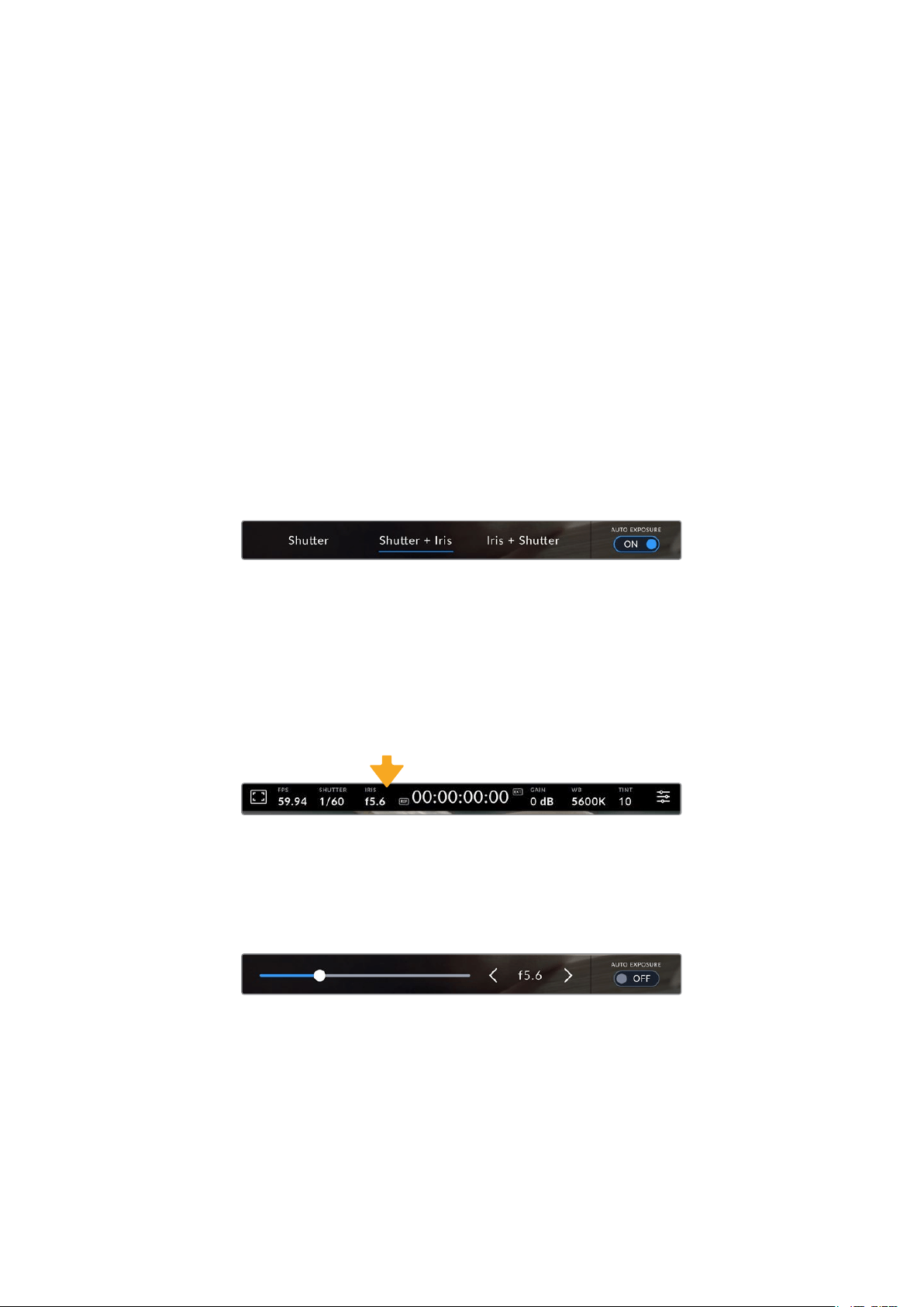
Shutter + Iris
Maintains the correct exposure levels by adjusting the shutter, then the aperture. If the
maximum or minimum available shutter value is reached and exposure still cannot be
maintained, your camera adjusts the aperture to keep exposure consistent.
Iris + Shutter
Maintains the correct exposure levels by adjusting the aperture, then the shutter value. If the
maximum or minimum available aperture is reached and exposure still cannot be maintained,
your camera adjusts the shutter value to keep exposure consistent.
While in the shutter menu, tap ‘auto exposure’ to access shutter based auto
exposure modes
When an auto exposure mode that effects the shutter or iris is enabled, a small ‘A’ appears next
to the shutter or iris indicator at the top of the LCD touchscreen.
Iris
The ‘Iris’ indicator displays your current lens aperture. By tapping this indicator, you can change
the aperture of compatible lenses and configure iris based auto exposure modes.
Tap the iris indicator to access iris settings
Tapping the ‘iris’ indicator once brings up the iris menu along the bottom of the touchscreen.
You’ll see your current lens aperture at the far left of this menu. You can change the aperture
by tapping the left and right arrows on either side of the current aperture, or moving the slider
left or right.
While in the ‘iris’ menu, tap the arrows on either side of the iris indicator or use
the slider to adjust iris settings
Tapping the ‘auto exposure’ switch icon at the far right of the iris menu opens the iris auto
exposure menu.
This gives you the following auto exposure options.
37Touchscreen Controls
Iris
This setting automatically adjusts the aperture to maintain a constant exposure while keeping
shutter speed consistent. This will keep motion blur unaffected, but may affect your depth of field.
Iris + Shutter
Maintains the correct exposure levels by adjusting the aperture, then the shutter value. If the
maximum or minimum available aperture is reached and exposure still cannot be maintained,
your camera adjusts the shutter value to keep exposure consistent.
Shutter + Iris
Maintains the correct exposure levels by adjusting the shutter, then the aperture. If the
maximum or minimum available shutter value is reached and exposure still cannot be
maintained, your camera adjusts the aperture to keep exposure consistent.
While in the iris menu, tap ‘auto exposure’ to access iris based auto exposure modes
When an auto exposure mode that effects the iris or shutter is enabled, a small ‘A’ appears next
to the iris or shutter indicator at the top of the LCD touchscreen.
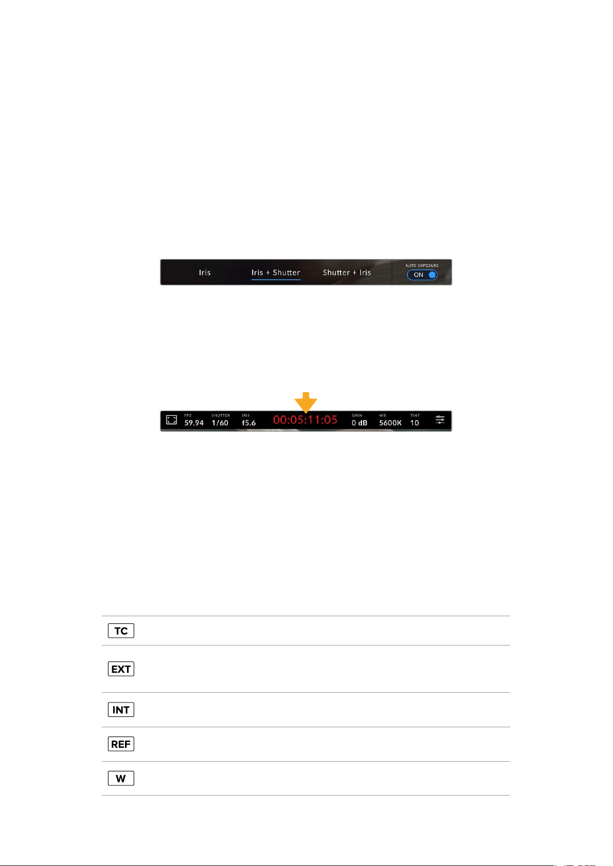
Duration Display
At the top of your camera’s LCD touchscreen, you’ll see your camera’s duration display.
Your camera’s duration display will turn red while recording.
The duration display provides a timecode counter for checking the duration of your clips
and monitoring timecode during recording. The counter displays a time sequence showing
Hours:Minutes:Seconds:Frames and will change accordingly as you record or play back clips.
During recording the timecode is red.
The displayed duration starts from 00:00:00:00. The clip duration of the current or last
recorded clip is displayed on the touchscreen. Time of day timecode is embedded into clips for
easier post production.
To see the timecode, simply tap the duration display. Tap the duration display again to return to
clip duration.
Additional status indicators may appear around the duration display:
Appears to the right of the duration display when showingtimecode.
Appears to the right of the duration display if an external timecode signal is connected and
valid. This can be fed from an ATEM Mini via HDMI, an ATEM switcher via SDI Program return
or from an analog mini jack or XLR timecode source.
Appears to the right of the duration display if the camera isrunning off an internal timecode
after being ‘jam synced’ anddisconnected.
Appears when a valid reference source is connected and locked, based on the reference
input settings.
Appears to the left of the duration display when Blackmagic Studio Camera 6K Pro is using a
windowed sensor mode.
38Touchscreen Controls
When connected to ATEM switchers, your studio camera will display a small tally status overlay
on the LCD touchscreen below the timecode. This means you can disable the tally light on the
camera, but still see if your studio camera has been switched to the preview output or is live to air.
ATEM switchers automatically synchronize the timecode on your studio camera to match the
switcher’s timecode when connected. This makes it easier to perform accurate multi camera
edits in DaVinci Resolve.
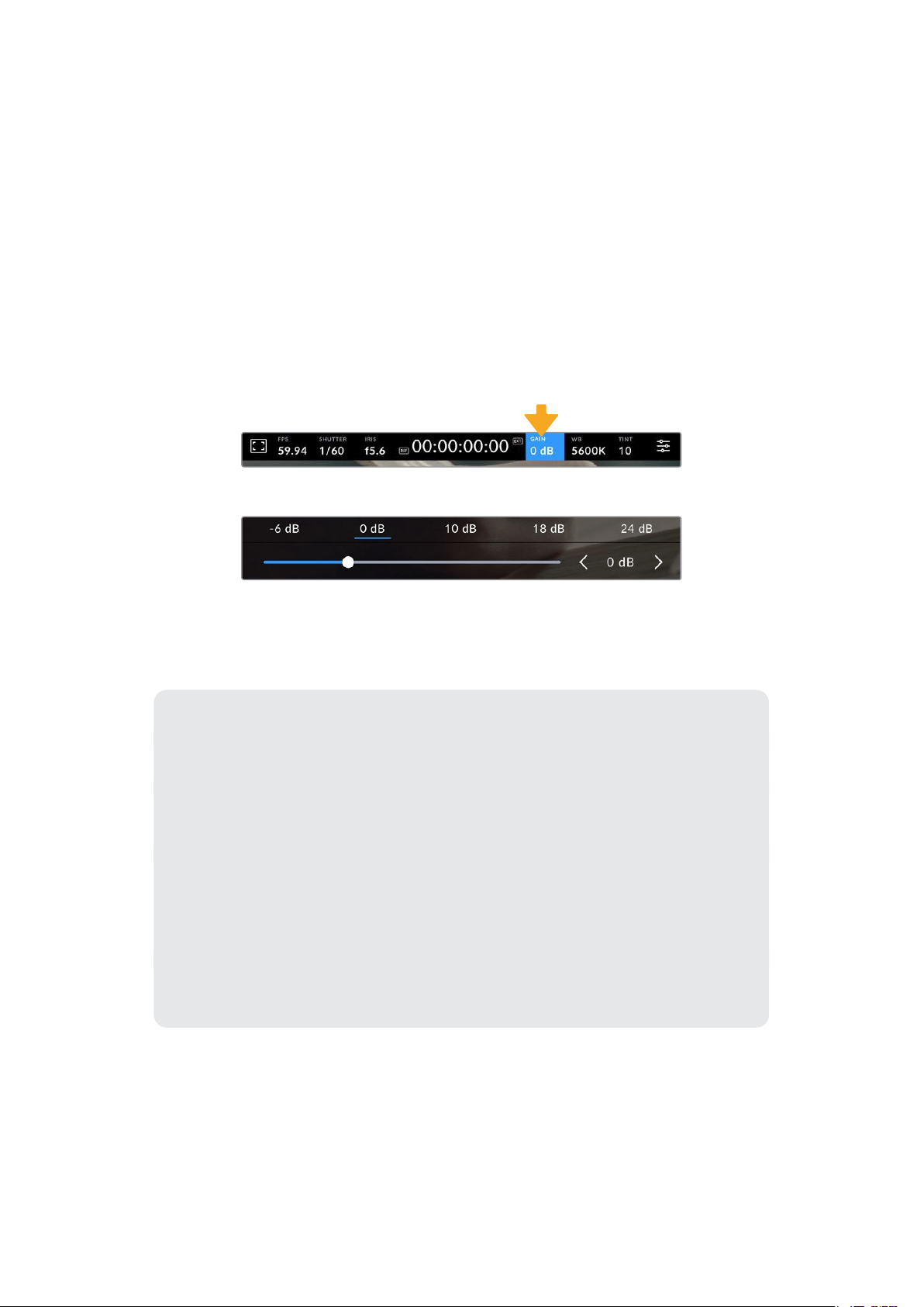
Gain
The ‘gain’ indicator displays your studio camera’s current gain setting, or light sensitivity.
Tapping this indicator lets you adjust your gain to suit varying lighting conditions.
The optimum setting for your studio camera is 0dB. Your camera has a dual native ISO sensor,
meaning that 10dB and 18dB are excellent for low light situations, producing clean images with
very little noise.
Tap the gain indicator to access gain settings
The slider and arrows below the presets let you adjust the gain in 1/3 stop increments
Depending on your situation, you may choose a lower or higher gain setting. For example,
32or36dB can be used in ultra low light but may cause noise.
Dual Native Gain
The sensor in your Blackmagic Studio Camera is optimized for shooting in low light
conditions as well as bright daylight.
Adjust the gain for the varying lighting conditions and the dual native gain feature will
operate in the background to make sure your footage is clean and has minimal noise at
low and high gain settings.
When the gain setting is between -12dB and 8dB the native gain of 0dB is used as a
reference point. The gain range between 10dB and 36dB uses the native gain of 18dB
as a reference. If you are shooting in conditions where you have a choice between
8dB or 10dB we suggest closing down one stop on your lens’ iris so that you can select
10dB as it will engage the higher native gain and provide much cleaner results.
The dynamic range charts in this section show the relationship between the gain
selection and dynamic range allocation.
39Touchscreen Controls
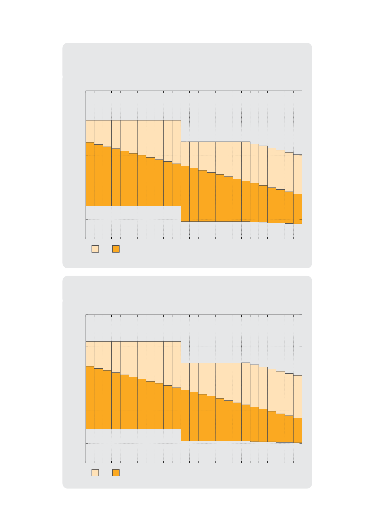
Blackmagic Studio Camera 4K Plus and
Blackmagic Studio Camera 4K Pro Models Dynamic Range
3.5
9.8
3.8
9.5
4 .1
9.2
4.5
8.8
4.8
8.5
5 .1
8.2
5.5
7. 8
5.8
7. 5
6 .1
7. 2
6.5
6.8
6.8
6.5
3.9
8.5
4 .1
8.3
4.5
7. 9
4.9
7. 5
5.2
7. 2
5.5
6.9
5.9
6.5
6.2
6.2
6.2
6
6.2
5.7
6 .1
5.5
6.2
5.2
6.2
4.9
6 .1
4.7
stops
Stops Above Stops Below
-10
-5
5
10
0
-12dBGain
Total Stops
-10dB -8dB -6dB -4dB -2dB 0dB 2dB 4dB 6dB 8dB 10dB 12dB
14dB
16dB 18dB 20dB 22dB 24dB 26dB 28dB 30dB 32dB 34dB 36dB
13.3 13.3 13.3 13.3 13.3 13.3
13.3
13.3 13.3 13.3 13.3 12.4 12.4 12.4 12.4 12.4 12.4 12.4 12.4 12.2 11.9 11.6 11.4
11.1
10.8
Blackmagic Studio Camera 6K Pro Dynamic Range
3.9
9.8
4.3
9.4
4.6
9.1
4.9
8.8
5.3
8.4
5.6
8 .1
5.9
7. 8
6.3
7. 4
6.6
7.1
6.9
6.8
7. 3
6.4
4.3
7. 9
4.6
7.6
4.9
7. 3
5.3
6.9
5.6
6.6
5.9
6.3
6.3
5.9
6.6
5.6
6.6
5.3
6.6
5 .1
6.7
4.7
6.6
4.5
6.6
4 .1
6.6
3.8
stops
Stops Above Stops Below
-10
-5
5
10
0
-12dBGain
Total Stops
-10dB -8dB -6dB -4dB -2dB 0dB 2dB 4dB 6dB 8dB 10dB 12dB
14dB
16dB 18dB 20dB 22dB 24dB 26dB 28dB 30dB 32dB 34dB 36dB
13.7 13.7 13.7 13.7 13.7 13.7
13.7
13.7 13.7 13.7 13.7 12.2 12.2 12.2 12.2 12.2 12.2 12.2 12.2 11.9 11.7 11.4 11.1
10.7
10.4
40Touchscreen Controls
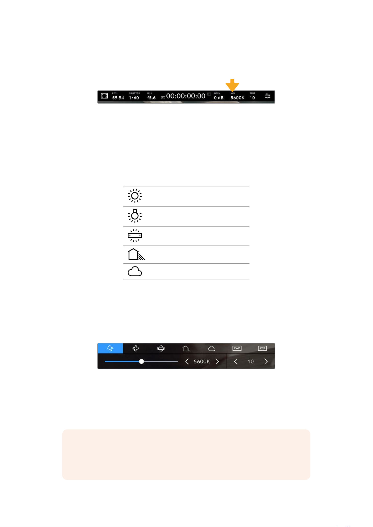
White Balance
The ‘WB’ and ‘TINT’ indicators display your camera’s current white balance and tint. Tapping these
indicators lets you adjust your camera’s white balance and tint to suit varying lighting conditions.
Tap the white balance and tint indicators to access white balance and tint settings
Every light source emits a color. For example, a candle flame emits a warm color, and an
overcast sky emits a cool color. White balance settings are used to color balance your image
so white stays white by adjusting the mix of orange and blue in your image. For example, when
shooting under tungsten lamps which emit a warm, orange light, selecting 3200K adds some
blue to the image. This balances the color so white is accurately recorded.
Your Blackmagic Studio Camera comes with white balance presets for a variety of color
temperature conditions. These are:
Bright sunlight (5600K)
Incandescent bulbs (3200K)
Fluorescent bulbs (4000K)
Mixed light (4500K)
Cloud (6500K)
To customize the presets, tap or tap and hold the arrow icons to the left and right of the
temperature indicator. Each tap moves the color temperature up or down 50K. Holding the arrow
icons down will increase the speed. Alternatively, you can drag the temperature slider left or right.
To further dial in your image, you can adjust the ‘tint.’ This adjusts the mix of green and magenta
in your image. For example, adding some magenta can compensate for the green cast of many
fluorescent lights. Many of your camera’s white balance presets include some tint.
Tapping the white balance and tint indicator gives you access to five presets, as
well as a white balance indicator and slider on the left, and a tint indicator on the
right. Adjust these to set a custom white balance for your lighting conditions.
In a similar fashion to white balance, tap the tint indicator’s left and right arrows to make a
change. The available range is -50 to +50 in one unit steps. Holding down on the arrows
speeds up adjustment.
NOTE Customizing the white balance or tint will change your preset to ‘CWB,’ or
custom white balance. Custom white balances are persistent; your CWB settings will
stay configured between power cycles, and when switching to a preset and back to
CWB. This makes it easy to compare a custom white balance to the last preset used.
41Touchscreen Controls
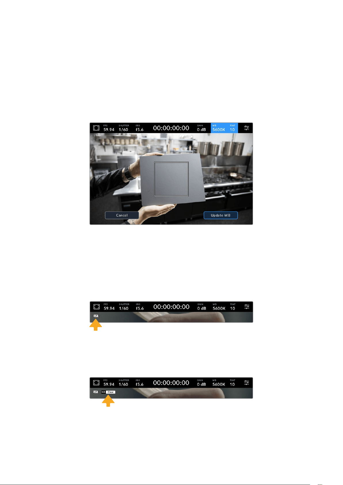
Auto White Balance
Your Blackmagic Studio Camera can set white balance automatically. Tapping ‘AWB’ will open
the white balance screen.
When setting white balance automatically, a square will be overlaid on the center of your image.
Fill this square with a neutral surface such as a white or gray card and tap ‘update WB’. The
camera will automatically adjust its white balance and tint values so the average of the white or
gray inside the white balance square is as neutral as possible. Once updated, this will be set as
your camera’s custom white balance. Holding the WB button on the top of your camera for three
seconds also selects automatic white balance and activates the ‘update WB’ function.
Tapping the ‘AWB’ icon in the white balance menu will bring up the auto white
balance screen. Use this with a white or neutral gray surface to automatically set
a neutral white balance.
LUT Indicator
When you are using a LUT as a preview tool on set, a white LUT icon will be displayed in the top
left corner of the screen to indicate that a LUT is currently active. This icon will be blue if you
have ‘Apply LUT in File’ switched on in the ‘record’ settings. For more information refer to the
‘record settings’ section.
ND Filter Indicator
Blackmagic Studio Camera 6K Pro has an ND filter indicator in the top left of the LCD
touchscreen and any SDI or HDMI outputs set to show status text. The indicator uses the format
you have selected in the ‘setup’ menu.
42Touchscreen Controls
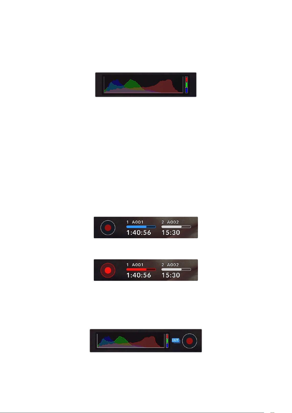
Histogram
At the bottom left of your camera’s touchscreen you can see the histogram. The RGB
histogram shows the tonal distribution of the image separated into individual red, green and
blue channels.
The histogram gives you an indication of the tonal
range between shadows and highlights in your clip.
The left edge of the histogram displays shadows, or blacks, and the far right displays highlights,
or whites. When you close or open the lens aperture, you’ll notice the information in the
histogram moves to the left or right accordingly. You can use this to check ‘clipping’ in your
image shadows and highlights. When clipping occurs in the red, green or blue channel, the
respective indicator on the right side of the histogram lights up. If the left and right of your
edges of the histogram come to an abrupt stop rather than falling off gradually, you may be
losing highlight or shadow detail.
If you don’t see a histogram in the bottom left of your touchscreen, your LCD monitor settings
may be set to display ‘codec and resolution.’ See the ‘monitor settings’ section in this manual
formore information.
Record Button
Next to the histogram at the bottom of your studio camera’s touchscreen is the ‘record’ button.
Tap this button once to begin recording and tap it again to stop. While recording, the button,
media bar icon and the timecode at the top of your camera’s touchscreen will turn red.
The record button is located next to the storageindicators
at the bottom of the LCD touchscreen
When recording, the record button and media bar illuminates red
Apply LUT in File
If you have chosen to apply a LUT to your recorded clips in the ‘record’ settings tab, a blue ‘LUT’
icon is displayed next to the ‘record’ button. The LUT indicator is displayed in both standby and
record mode.
For more information on recording LUTs with Blackmagic RAW files, refer to the ‘record settings’
section later in this manual.
43Touchscreen Controls
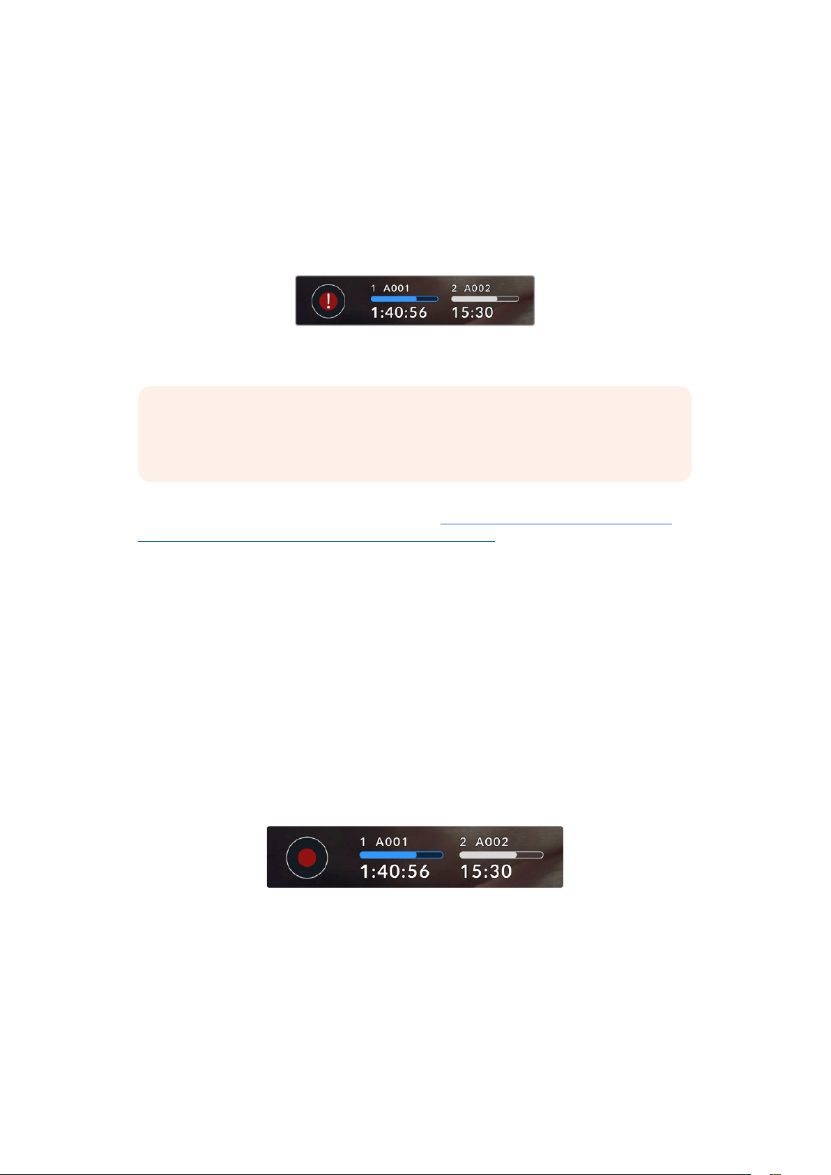
Dropped Frame Indicator
The ‘record’ button is overlaid with a flashing ‘!’ indicator if your camera begins dropping frames
while recording. The time remaining indicator for the affected flash disk also turns red. For
example, if your USB-C flash disk is dropping frames, the ‘!’ indicator appears over the ‘record’
button, and the time remaining indicator on the flash disk turns red. This lets you know if a
particular flash disk is too slow for your currently selected codec and resolution. The ‘dropped
frame indicator’ also appears if you have dropped a frame on the previously recorded clip. This
indicator continues until another clip is recorded, or the camera is power cycled.
The dropped frame indicator appears when a
flashdiskis dropping frames
NOTE You can set your Blackmagic Studio Camera to stop recording if dropped
frames are detected to avoid recording unusable footage. See the ‘record settings’
section in this manual for more information.
You can estimate different record duration times based on USB-C drive capacity, frame rate
and codec settings using the data rate calculator at:
https://blackmagicdesign.com/products/
blackmagicstudiocamera/blackmagicraw#data-rate-calculator
Storage Indicators
Storage indicators are visible at the bottom of your studio camera’s touchscreen next to
the ‘record’ button. These indicators display information about USB-C drives connected to
your camera.
Record Time Remaining
When a USB-C flash disk is connected to your camera, the storage indicator at the bottom of
the touchscreen show how much recording time is left on the disk. The time is shown in hours,
minutes and seconds and varies according to your selected frame rate and codec. The indicator
automatically recalculates if either of these settings are changed.
When there is approximately 5 minutes remaining on your flash disk, the storage indicator text
will turn red. If you are recording to a single disk or have filled an additional flash disk attached
to your camera, the indicator will blink slowly when there is 3 minutes remaining and blink
quickly when there is less than 30 seconds of recording time remaining.
The storage indicator shows the name of your flash disk
andtheavailablerecord time
44
Touchscreen Controls
Media Bar
The media bar icon above the recording time will be either blue, white or red depending on its
current status and will display the used space on the USB-C flash disk.
The blue icon indicates the active flash disk. Thisis the disk that will be
used for recording.
A white icon indicates that there is a USB-C flash disk present, butnot
active. A solid white icon indicates the disk is full.
The bar will illuminate red during recording.
To switch recording to a different disk, press and hold the name or media bar of the USB-C
flash disk that you wish to record to.
Tapping the storage indicators will bring up the storage and formatting menu.
Tap the storage indicator on the LCD touchscreen to access the storage manager
The storage menu displays the amount of free space on each USB-C flash disk currently
connected to your studio camera, as well as the name of the disk, available record time, total
number of clips and the file format. Tapping the flash disk in the storage menu sets it as the
active disk and your studio camera will fill this disk first. You can also format your media from
this menu. For more information on connecting and formatting USB-C flash disks for your Studio
Camera, see the ‘storage media’ section of this manual.
45Touchscreen Controls
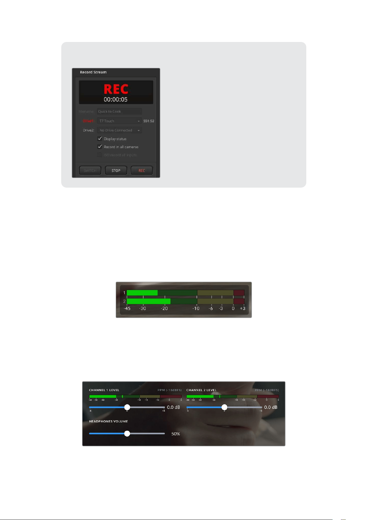
Triggering Record using ATEM Mini or ATEM SDI
When recording ISO files from an ATEM Mini
or ATEM SDI Extreme or Pro model switcher,
youcan also trigger record on all connected
Blackmagic Studio Cameras.
For example, the ‘record stream’ palette in ATEM
Software Control has a checkbox labeled ‘record
in all cameras’. When this checkbox is enabled
and you click or press record, all connected
studio cameras will start recording as well. This
means you only have to click or press one button
to start recording on all cameras simultaneously.
Refer to the ATEM Mini or ATEM SDI manual for
more information.
Audio Meter
The peak audio meters display audio levels for channels 1 and 2 when using the internal
microphone, or via external audio when connected. You can display PPM or VU meters.
Tochange the meter type, see the ‘setup’ settings section later in this manual.
To achieve optimum audio quality using PPM meters, ensure your levels do not reach 0
dBFS. This is the maximum level that your camera can record before the audio is clipped and
distortion occurs.
Alternatively, when using VU meters, levels can safely peak at 0, allowing you a little room
beyond 0 before clipping occurs. To avoid clipping, make sure the levels do not reach +3 dBFS.
The colored bars on the VU audio meter represent peak
audio levels. Ideally your peak audio levels should fall
in the upper end of the green zone. If your peaks enter
into the yellow zone your audio is near clipping. Audio in
the red zone reaching +3 dBFS is at risk of clipping.
You can tap the audio meters to open a more detailed meter display and level controls
foraudioinput channels 1 and 2. You can also adjust the headset volume.
Tap the audio meters on the LCD touchscreen to access audio channel and headset volume
controls. For more information, see the ‘audio settings’ section inthis manual.
46
Touchscreen Controls
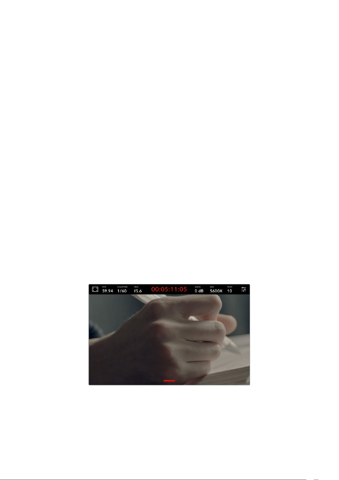
Touchscreen Gestures
Your Blackmagic Studio Camera’s touchscreen lets you use touch, pinch and tap gestures to
focus, zoom and navigate around your preview image.
Double Tap to Zoom
You can magnify any part of your Blackmagic Studio Camera’s preview image by double
tapping the LCD touchscreen. The area you tap will be magnified, and you can move around
the image by dragging your finger around the LCD touchscreen or by turning the settings dial.
This is very helpful when checking focus. To return to standard magnification, simply double tap
your camera’s touchscreen again.
The digital zoom feature can be assigned to a function button and is referred to as ‘focus zoom’.
Pinch to Zoom
You can adjust the zoom level on the LCD touchscreen with a pinch to zoom multitouch gesture.
This does not affect the HDMI or SDI outputs.
To start zooming at x2, double tap on the touchscreen. Pinch out to increase magnification and
pinch in to decrease. Touch and drag to move the magnified area. To return to the standard
magnification, double tap on the touchscreen again.
Touch to Focus
You can focus your lens in any region of the image by tapping and holding on the LCD screen in
the area that you want to focus. If you want to focus on a magnified area of the screen, double
tap and then tap and hold to auto focus. Double tap to return to normal viewing.
Full Screen Mode
It can be useful when framing or focusing a shot to temporarily hide the lower third overlays on
the touchscreen, for example the histogram, storage indicators and audio meters. The status
display at the top of the screen features above and separate from the image, so is always
visible. To hide lower third overlays, swipe up or down on the LCD touchscreen. The record
indicator, frame guides, grids, focus assist and zebra remain visible.
Swipe up or down to hide lower third overlays on the LCD touchscreen
47
Touchscreen Controls
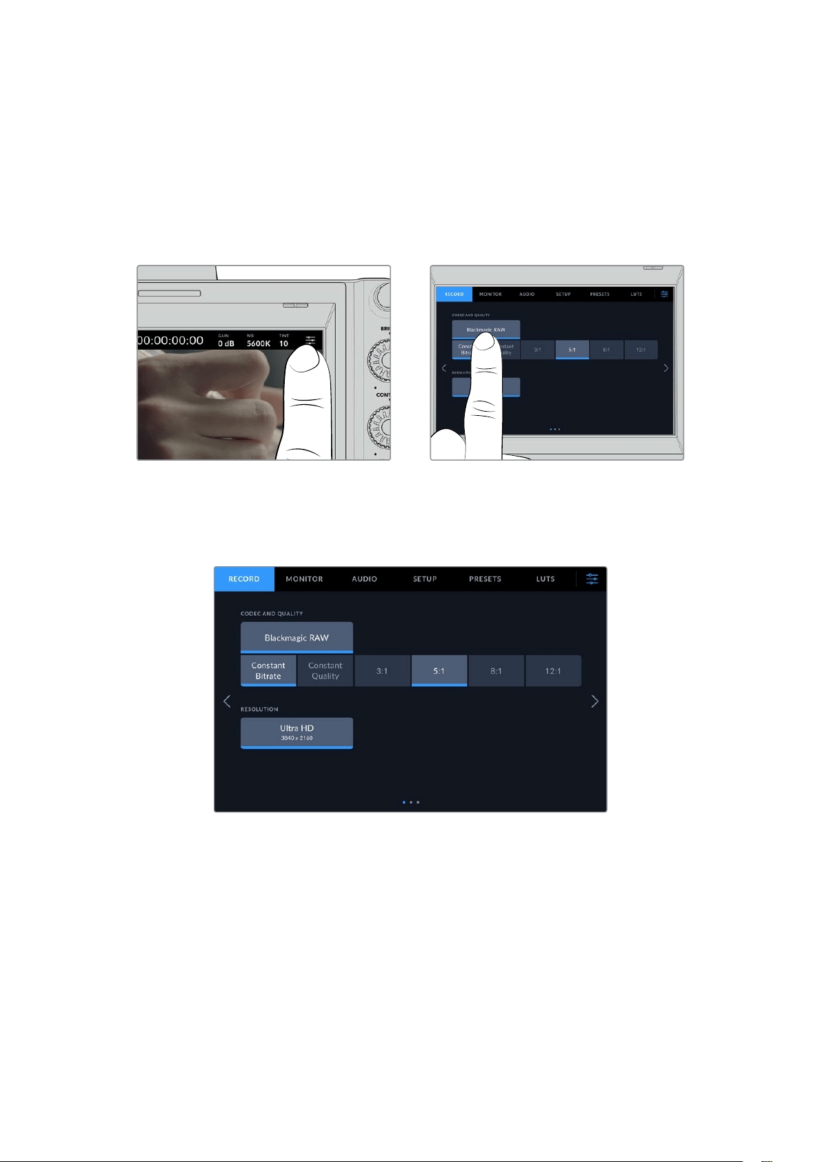
Menu Settings
While the head up display lets you quickly change some important settings, all of your camera’s
settings are accessed using the main menu settings.
To open the settings menu and make a change, simply tap on the menu button in the top right
hand corner. This opens the settings menu on the LCD and you can now tap and swipe items to
make changes.
Tap the menu settings icon and use the touchscreen to change settings
Settings are divided by functions into ‘record,’ ‘monitor,’ ‘audio,’ ‘setup,’ ‘presets,’ and ‘LUTs’
tabs. Each tab has multiple pages, which you can cycle through by tapping the arrows at the
edge of your camera’s touchscreen, or swiping left or right.
Tap the ‘record’, ‘monitor’, ‘audio’, ‘setup’, ‘presets’ and ‘LUTs’ headings to move
throughyour studio camera’s menu tabs
Record Settings
The ‘record’ tab lets you set your video format, codec, and resolution, as well as other settings
that are important for your recorded video, such as dynamic range and detail sharpening.
Youcan also set the codec and quality for when recording to a USB-C flash disk.
Record Settings Page 1
The first page of the ‘record’ settings tab contains the following settings.
48Menu Settings
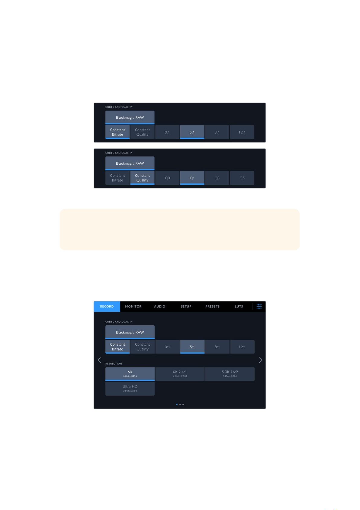
Codec and Quality
The ‘codec and quality’ menu lets you set the quality for Blackmagic RAW when recording
externally. You can choose from a selection of constant bitrate settings, or constant quality.
Forexample 3:1, 5:1, 8:1, 12:1, or Q0, Q1, Q3 and Q5 respectively. These provide options so you
can set the amount of compression used. More information on Blackmagic RAW is provided
later in this section.
Blackmagic RAW quality options
TIP You can increase the recording durations on external storage media connected
to your Blackmagic Studio Camera if you choose codecs that use higher compression.
Refer to the ‘record duration’ tables in the ‘recording’ section for more information.
Resolution
This setting displays the resolution being recorded if you are recording to an external flash
disk via USB-C. On Blackmagic Studio Camera 4K Plus and 4K Pro models you can record in
UltraHD. On Blackmagic Studio Camera 6K Pro you can choose to record in Ultra HD, 5.3K or
6K resolutions.
The resolution options on Blackmagic Studio Camera 6K Pro
49
Menu Settings

Blackmagic RAW
Blackmagic Studio Cameras support the Blackmagic RAW file format. This format offers superior
image quality, wide dynamic range and a broad selection of compression ratios. Blackmagic
RAW features all the user benefits of RAW recording, but the files are very fast because most
of the processing is performed in the camera where it can be hardware accelerated by the
camera itself.
Blackmagic RAW also includes powerful metadata support so the software reading the files
knows your camera settings. If you like shooting in video gamma because you need to turn
around edits quickly and you don’t have time for color correction, then this metadata feature
means you can select video gamma, shoot in video gamma, and the file will display with video
gamma applied when you open it in software. However underneath, the file is actually film
gamma and the metadata in the file is what’s telling the software to apply the video gamma.
So what all this means is if you want to color grade your images at some point, then you have
all that film dynamic range preserved in the file. You don’t have your images hard clipped in the
whites or the blacks, so you retain detail and you can color grade to make all your images look
cinematic. However, if you don’t have time for color grading, that’s fine because your images
will have the video gamma applied and look like normal video camera images. You are not
locked in on the shoot and you can change your mind later during post production.
Blackmagic RAW files are fast with the codec optimized for your computer’s CPU and GPU.
This means it has fast smooth playback and eliminates need for hardware decoder boards,
which is important for laptop use. Software that reads Blackmagic RAW also gets the advantage
of processing via Apple Metal, Nvidia CUDA and OpenCL. Blackmagic RAW plays back at
normal speed like a video file on most computers, without needing to cache it first or lower the
resolution.
It’s also worth mentioning that lens information is recorded in the metadata on a frame by frame
basis. For example, when using compatible lenses, any zoom or focus changes performed over
the length of a clip will be saved, frame by frame, to the metadata in the Blackmagic RAW file.
Recording to Blackmagic RAW
Blackmagic RAW works in 2 different ways. You have a choice to use either the constant bitrate
codec, or the constant quality codec.
Constant bitrate codec works in a similar way to most codecs. It tries to keep the data rate at a
consistent level and won’t let the data rate go too high. This means even if you are shooting a
complex image that might need a bit more data to store the image, a constant bitrate codec will
compress the image harder to make sure the images fit within the space allocated.
This can be fine for video codecs, however when shooting Blackmagic RAW you really want to
ensure the quality is predictable. What would happen if the images you were shooting needed
more data, but the codec just compresses harder to make a specified data rate? It’s possible
you could lose quality, but not be sure it’s happening until you return from a shoot.
To solve this problem, Blackmagic RAW also has an alternative codec choice called constant
quality. This codec is technically called a variable bitrate codec, but what it’s really doing is
allowing the size of the file to grow if your images need extra data. There is no upper limit on
the file size if you need to encode an image but maintain quality.
So Blackmagic RAW set to the constant quality setting will let the file grow as big as it needs to
be to encode your images. It also means the files could be larger or smaller depending on what
you are shooting.
50Menu Settings

It is also worth noting that the quality settings for Blackmagic RAW are not obscure names,
butare more meaningful as they are derived from what’s happening technically. So for example
when you have selected the constant bitrate codec, you will see quality settings of 3:1, 5:1, 8:1
and 12:1. These are the ratios of the uncompressed RAW file size vs the file sizes you should
expect when shooting in Blackmagic RAW. 3:1 is better quality as the file is larger, while 12:1
is the smallest file size with the lowest quality. Many users of Blackmagic RAW find that 12:1
has been perfectly ok and they have not seen any quality limitations. However it’s best to
experiment and try various settings for yourself.
When using Blackmagic RAW in constant quality you will see the settings are Q0, Q1, Q3 and
Q5 on your studio camera. These are the compression parameters passed to the codec and
they are setting how much compression is applied in a more technical way. This setting is
different because the codec operates differently between constant bitrate vs constant quality.
In this constant quality setting, you really cannot tell what the file size ratio will become as it
varies a lot based on what you are shooting. So in this case the setting is different and the file
will become the size needed to store your media.
Constant Bitrate Settings
The names for 3:1, 5:1, 8:1 and 12:1 represent the compression ratio. For example, 12:1
compression produces a file size roughly 12 times smaller than uncompressed RAW.
Constant Quality Settings
Q0 and Q5 refer to different levels of quantization. Q5 has a greater level of quantization but
offers a greatly improved data rate. As mentioned above, the constant quality setting can result
in files that grow and shrink quite a lot, depending on what you are shooting. This also means
it’s possible to shoot something and see the file size increase to beyond what your media
drive can keep up with. It could result in dropped frames. However the benefit is that you can
instantly see if this happens on a shoot and then investigate your settings vs quality.
Blackmagic RAW Player
The Blackmagic RAW player included in your Blackmagic camera’s software installer is a
streamlined application for reviewing clips. Simply double click on a Blackmagic RAW file to
open it, and you can quickly play and scroll through the file with its full resolution and bit depth.
When decoding frames, CPU acceleration in SDK library supports all main architectures, and
also supports GPU acceleration via Apple Metal, Nvidia CUDA and OpenCL. It also works with
the Blackmagic eGPU for extra performance. Blackmagic RAW player is available for Mac,
Windows and Linux.
Sidecar Files
Blackmagic RAW sidecar files let you override metadata in a file without overwriting embedded
metadata in the original file. This metadata includes the Blackmagic RAW settings as well as
information on iris, focus, focal length, while balance, tint, color space, project name, take
number and more. Metadata is encoded frame by frame over the duration of the clip, which is
important for lens data if the lens is adjusted during a shot. You can add or edit metadata in
sidecar files with DaVinci Resolve or even a text editor because it’s a human readable format.
Sidecar files can be used to automatically add new Blackmagic RAW settings to a playback
simply by moving the sidecar file into the same folder as the corresponding Blackmagic RAW
file. If you move the sidecar file out of the folder and reopen the Blackmagic RAW file, the
changed settings are not applied and you see the file as it was originally shot. Any software
that uses the Blackmagic RAW SDK can access these settings. Changes made are saved in the
sidecar file and can then be seen by Blackmagic RAW Player or any other software capable of
reading Blackmagic RAW files.
51Menu Settings
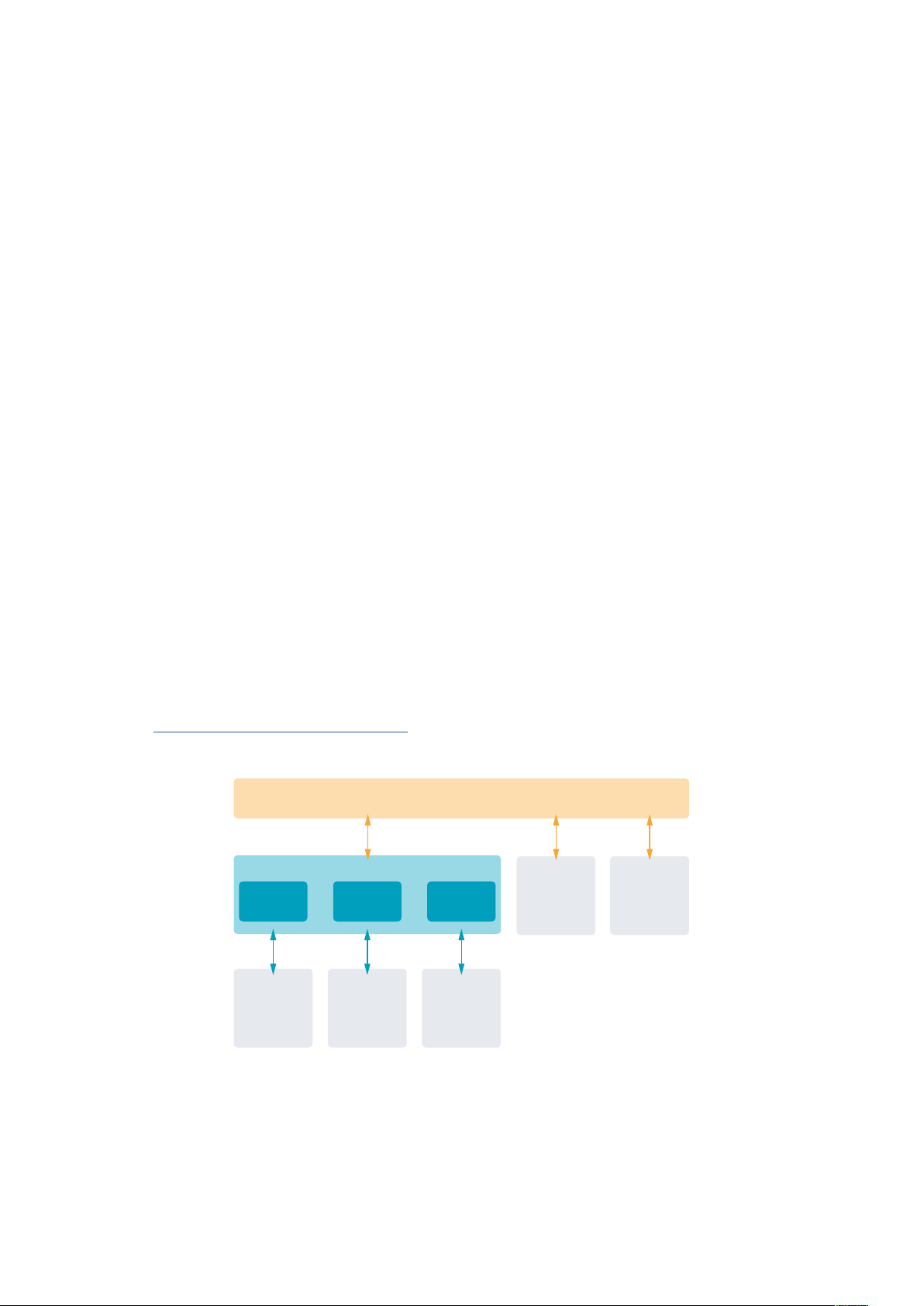
When shooting video gamma, the file stays in film gamma, and the metadata tells the
Blackmagic RAW processing to display using video gamma. Video gamma is great when you
don’t want to grade the image and want to deliver content quickly, however if you want to pull
up the black parts of the image, or pull down the white areas, all the detail is retained. You
never clip the video and all the detail is still there if you want to access it at any time.
Blackmagic RAW in DaVinci Resolve
Settings can be adjusted for each Blackmagic RAW file, and then saved as a new sidecar file
from the ‘Camera RAW’ tab in DaVinci Resolve for creative effect or optimized viewing. This also
means you can copy your media for another DaVinci Resolve artist and they will have access to
your modified gamma settings automatically on import. In addition to the other metadata your
camera files contain, DaVinci Resolve can read your selected dynamic range, so your clips will
automatically display in DaVinci Resolve with ‘film’, ‘extended video’ or ‘video’ dynamic range.
You can then customize these settings by adjusting the saturation, contrast and midpoint, as
well as the highlight and shadow rolloff. Any adjustments can then be saved as a sidecar file,
sothe changes can be seen by anyone else working with the files in post. You can always
return to the original camera metadata at any time.
You can also export a single Blackmagic RAW frame from the ‘Camera RAW’ tab in DaVinci
Resolve, which contains all adjustments, metadata, full resolution and color information so it is
easy to share a single frame grab or reference file with others.
Blackmagic RAW Software Development Kit
The Blackmagic RAW Software Development Kit is an API developed by Blackmagic Design.
You can use the Blackmagic RAW SDK to write your own applications to use the Blackmagic
RAW format. This SDK library can be used by any developer to add support for reading,
editing, and saving Blackmagic RAW files. The Blackmagic RAW SDK includes all the
generation 4 and generation 5 color science so you can achieve organic cinematic images
across any app that supports it. The Blackmagic RAW SDK supports Mac, Windows and Linux,
and is available as a free download from the developer page of the Blackmagic website at
www.blackmagicdesign.com/developer
The following diagram illustrates the components of the Blackmagic RAW API:
Blackmagic RAW API
METAL
SSE
CUDA
AVX
Decoder
OPENCL
AVX2
.Braw
Reader
.Sidecar
Reader
52Menu Settings

Record Duration
The tables in this section show approximate record duration in minutes based on format,
projectframe rate and flash disk size.
The maximum recording time for a flash disk can vary depending on the data capacity of your
USB-C flash disk and the frame rate you choose. It should also be noted that the recording
duration for a flash disk can vary slightly between different manufacturers and whether the
storage media is formatted as exFAT or Mac OS Extended.
Simple scenes containing less detail tend to require less data than more dense compositions.
The values in these tables assume shots with a high complexity, which means you may get
slightly longer record times depending on the nature of your shoot.
TIP You can estimate record duration times based on different USB-C drive
capacities, frame rates and codec settings using the data rate calculator at:
https://blackmagicdesign.com/products/blackmagicstudiocamera/
blackmagicraw#data-rate-calculator
6K
USB Flash Disk Frame Rate
Blackmagic
RAW3:1
Blackmagic
RAW5:1
Blackmagic
RAW8:1
Blackmagic
RAW12:1
Duration Duration Duration Duration
1 TB
23.98 65 mins 108 mins 174 mins 260 mins
24 65 mins 108 mins 173 mins 260 mins
25 62 mins 104 mins 167 mins 250 mins
30 51 mins 87 mins 139 mins 208 mins
50 31 mins 52 mins 83 mins 125 mins
6K 2.4:1
USB Flash Disk Frame Rate
Blackmagic
RAW3:1
Blackmagic
RAW5:1
Blackmagic
RAW8:1
Blackmagic
RAW12:1
Duration Duration Duration Duration
1 TB
23.98 87 mins 146 mins 233 mins 349 mins
24 87 mins 146 mins 233 mins 349 mins
25 84 mins 140 mins 224 mins 335 mins
30 70 mins 116 mins 186 mins 279 mins
50 42 mins 70 mins 112 mins 168 mins
60 35 mins 58 mins 93 mins 140 mins
53Menu Settings
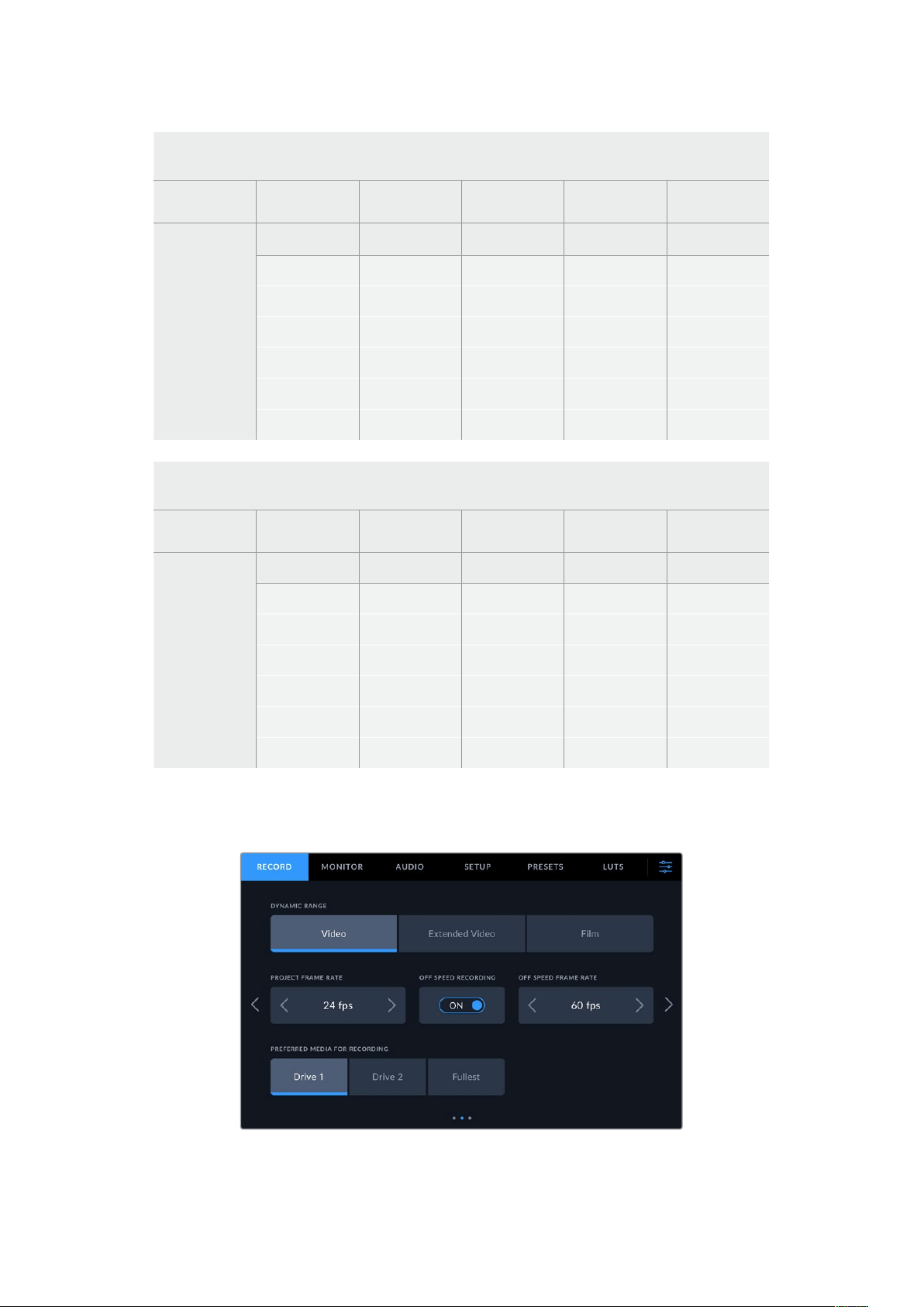
5.3K 16:9
USB Flash Disk Frame Rate
Blackmagic
RAW3:1
Blackmagic
RAW5:1
Blackmagic
RAW8:1
Blackmagic
RAW12:1
Duration Duration Duration Duration
1 TB
23.98 85 mins 141 mins 226 mins 338 mins
24 84 mins 141 mins 226 mins 338 mins
25 81 mins 135 mins 217 mins 324 mins
30 67 mins 113 mins 181 mins 270 mins
50 40 mins 67 mins 108 mins 162 mins
60 33 mins 56 mins 90 mins 135 mins
ULTR A HD
USB Flash Disk Frame Rate
Blackmagic
RAW3:1
Blackmagic
RAW5:1
Blackmagic
RAW8:1
Blackmagic
RAW12:1
Duration Duration Duration Duration
1 TB
23.98 164 mins 274 mins 436 mins 652 mins
24 164 mins 273 mins 436 mins 651 mins
25 158 mins 262 mins 419 mins 625 mins
30 131 mins 219 mins 349 mins 522 mins
50 79 mins 131 mins 210 mins 314 mins
60 65 mins 109 mins 175 mins 262 mins
Record Settings Page 2
The second page of the ‘record’ settings tab contains the following options.
Move through the pages of record settings to find the setting you want to change
54Menu Settings

Dynamic Range
Adjust the ‘dynamic range’ setting by tapping the dynamic range icons. Blackmagic Studio
Cameras have three dynamic range settings:
Video The ‘video’ setting is perfect for live to air broadcast and lets you work faster by
recording to a high contrast look suitable for direct delivery or minimal post processing.
Video uses Rec.709 primaries and has 6 stops over middle gray with another 3 stops in
specular highlights. This is a good option if you want an accurate starting point that still
has a pleasing gamma curve.
Extended
Video
The ‘extended video’ setting is based on Blackmagic Wide Gamut with contrast and
saturation applied. The most notable differences to the video mode come from the
magenta/green axis having less saturation which is more typical of print film, and even
more highlight roll off than video mode which causes highlights to desaturate more.
Ithas a slightly flatter gamma curve that results in less saturation.
Film The ‘film’ setting shoots video using a log curve that allows you to maintain the greatest
dynamic range and maximizes the information in your video signal to help you get the
most out of color grading software, such as DaVinci Resolve.
NOTE When recording Blackmagic RAW using ‘film’ dynamic range, the image will
appear dull and desaturated on your touchscreen. This is because the image file
contains a lot of data that hasn’t yet been graded to suit a standard display. However
you can monitor the video on the LCD, HDMI and SDI output using a display LUT, or
look up table, designed to simulate a standard contrast. For more information, refer to
the ‘3D LUTs’ section in this manual.
Project Frame Rate
Project frame rate provides a selection of frame rates commonly used in the film and television
industry. For example, 23.98 frames per second. This frame rate is normally set to match your
playback speed and audio sync used in your post production workflow and delivery requirements.
Eight project frame rates are available, including 23.98, 24, 25, 29.97, 30, 50, 59.94 and 60
frames per second.
NOTE When you coordinate a multi camera recording through ATEM Mini, Blackmagic
Studio Cameras will change their frame rate to match the frame rate setting of the
ATEM Mini. If you are working with an SDI based ATEM switcher, you will need to set
your project frame rate on your camera to match the switcher.
Off Speed Recording
By default, the project and sensor frame rates are matched for a natural playback speed.
Tapping the ‘off speed recording’ switch icon lets you set your sensor frame rate independently.
Off Speed Frame Rate
With ‘off speed recording’ enabled, tap the arrows next to the ‘off speed frame rate’ indicator to
set your camera’s sensor frame rate.
The sensor frame rate sets how many actual frames from the sensor are recorded every second
and will affect how fast or slow your video will play back at your set project frame rate.
55Menu Settings
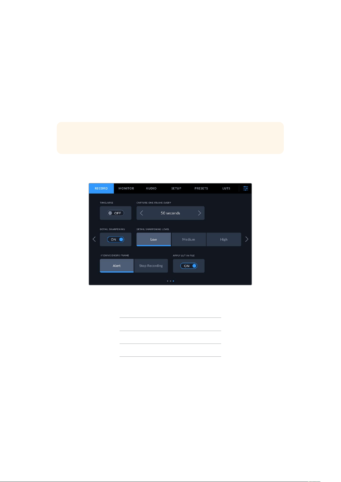
Preferred Media for Recording
When two USB-C flash disks are connected to your studio camera, you can use this setting to
determine which disk is recorded to first. The options are ‘drive 1’, ‘drive 2’ and ‘fullest’. Picking
either ‘drive 1’ or ‘drive 2’ is a matter of personal preference and when the selected drive fills
up, your camera will then continue recording on the alternate drive. ‘Fullest’ can help group files
chronologically when shooting a single camera project.
You can override this setting at any time by entering the storage manager and tapping the drive
name to set it as active. It’s important to note, however, that ejecting and reconnecting drives
reverts to the current ‘preferred drive for recording’ setting.
TIP The ‘fullest’ setting is based on the percentage that your recording media are
filled, rather than their sizes or the amount of data used.
Record Settings Page 3
The third page of the ‘record’ settings tab contains the following settings.
Timelapse
This setting activates the timelapse feature to automatically record a still frame at the
followingintervals:
Frames 2 – 10
Seconds 1 – 10, 20, 30, 40, 50
Minutes 1 – 10
For example, you can set the camera to record a still frame every 10 frames, five seconds,
30seconds, five minutes etc.
The timelapse feature offers many creative options. For example, setting a two frame timelapse
interval gives your recorded video a high speed effect when played back.
Start recording by pressing the record button. When you press the button again to stop
recording, the timelapse sequence is saved as one single clip, matching the codec and frame
rate set in your camera. This means you can drop the timelapse sequence into your post
production timeline just like any other clip you have recorded.
56Menu Settings

Timelapse mode is indicated by an
icon over the ‘record’ button
TIP When you record clips in timelapse mode, the timecode counter updates when a
frame of video is recorded.
Detail Sharpening
On Blackmagic Studio Camera 4K Plus and Pro, use this setting to sharpen the image.
Whensharpening is enabled, decrease or increase the level of sharpening by selecting ‘low’,
‘medium’ or ‘high’.
When enabled, sharpening will be applied to the HDMI and SDI outputs, but will not be
recorded via USB-C. This is because you will have more options and greater control over your
image using the sharpening tools in DaVinci Resolve.
If Drive Drops Frame
Use this setting to configure the behavior of your Blackmagic Studio Camera when dropped
frames are detected. When set to ‘alert,’ recording continues with dropped frames. When set to
‘stop recording,’ your camera stops recording if dropped frames are detected. This can prevent
you wasting time shooting unusable footage if you don’t notice the dropped frame indicator.
Apply LUT in File
When the ‘apply LUT in file’ switch is set to ‘on’ your Blackmagic Studio Camera will embed a
LUT into the Blackmagic RAW file you are recording. The LUT is saved into the header of the file
and can easily be applied to the clip in post production without needing to handle a separate
file. The clip will open in Blackmagic RAW Player and DaVinci Resolve with the LUT applied.
TheLUT can easily be toggled ‘on’ or ‘off’ but will always travel with the Blackmagic RAW file
asit is written into the clip itself.
DaVinci Resolve also has an ‘apply LUT’ checkbox in the RAW settings palette for enabling or
disabling the 3D LUT in the Blackmagic RAW file. The ‘Apply LUT’ setting in DaVinci Resolve is
the same setting as in the camera. This means that when shooting you can direct the colorist
to use the LUT by setting it in the camera, but they can switch it off easily in DaVinci Resolve by
deselecting the ‘apply LUT’ checkbox.
57Menu Settings
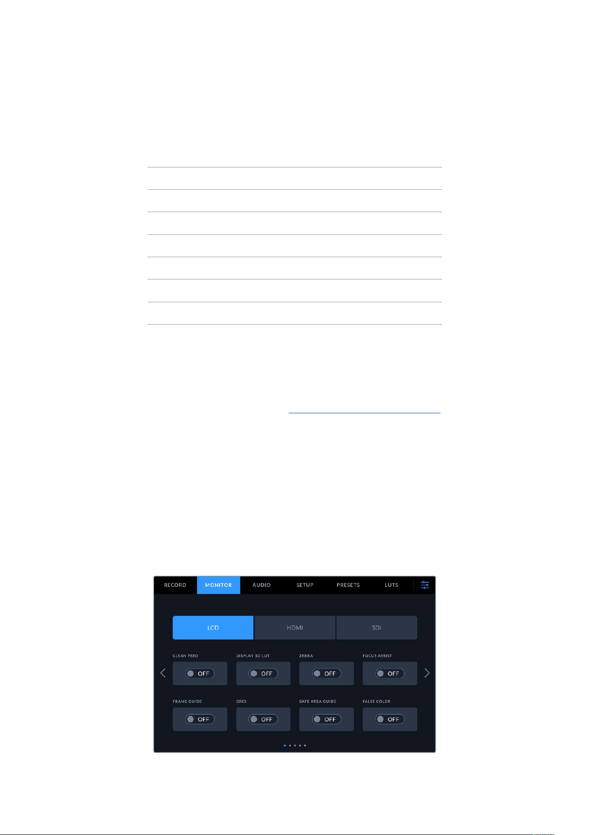
File Naming Convention
Clips are always recorded to your USB-C flash disk using Blackmagic RAW.
The table below shows an example of the file naming convention:
A001_08151512_C001.mov QuickTime Movie Filename
A001_08151512_C001.mov Camera Index
A001_08151512_C001.mov Reel Number
A001_08151512_C001.mov Month
A001_08151512_C001.mov Day
A001_08151512_C001.mov Hour
A001_08151512_C001.mov Minute
A001_08151512_C001.mov Clip Number
When you are recording camera ISO files from an ATEM Mini ISO or ATEM SDI ISO model
switcher, the clips’ file name will be determined by the ‘record stream’ palette in ATEM Software
Control. This means that the files can be identified and linked when the ATEM project is opened
in DaVinci Resolve.
For more information, please refer to the ‘ATEM Mini’ or ‘ATEM SDI’ manual which can be downloaded
from the Blackmagic Design support center at www.blackmagicdesign.com/support
Monitor Settings
The ‘monitor’ tab lets you adjust status text, overlays, and other monitoring options for your
studio camera’s LCD touchscreen, HDMI output and SDI output. Options are arranged by output
between ‘LCD’, ‘front SDI’ and ‘main SDI’. Each of these menus have five pages of options,
which you can cycle through by tapping the arrows at the edge of your camera’s touch screen,
or swiping left or right.
Monitor Settings 1
The first page of the monitor tab contains identical settings for each output. For example,
youcan set ‘zebra’ on for the LCD touchscreen, but off for the HDMI and SDI output.
58Menu Settings
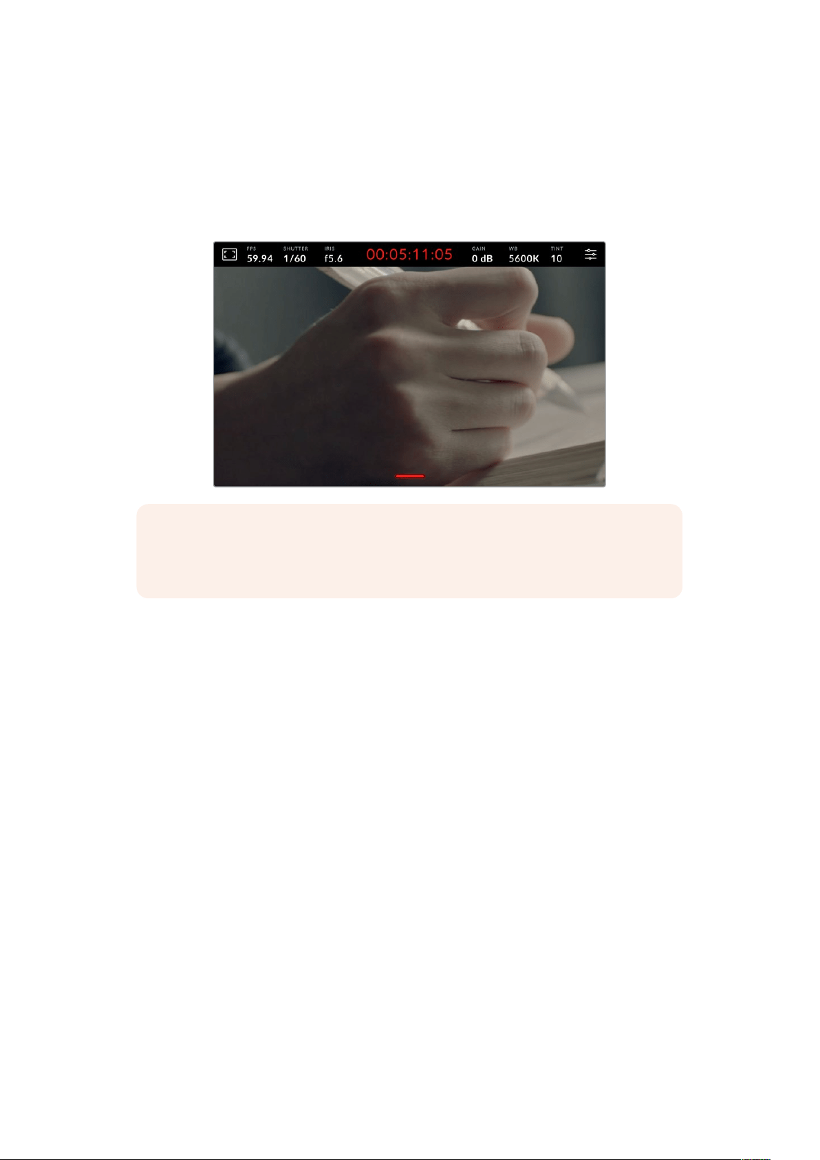
Clean Feed
Tap the ‘clean feed’ switch in the ‘LCD’, ‘HDMI’ or ‘SDI’ menus to disable all status text and
overlays for that output. The record tally will still be displayed on the LCD when clean feed
is applied.
It is a good idea to apply clean feed to outputs you are feeding to your switcher or any external
recorders when using a multicam setup.
NOTE A LUT will still be applied to outputs with ‘clean feed’ enabled. If you don’t want
to apply a LUT to an output, toggle the ‘display 3D LUT’ switch to ‘off’ in the ‘monitor’
menu for that output.
Display 3D LUT
Blackmagic Studio Cameras can apply 3D LUTs to any output to approximate the look of color
graded footage. This is especially useful when using ‘film’ dynamic range with its intentionally
‘flat’ low contrast image.
If your camera has a 3D LUT active, use this setting to independently apply that LUT to your
LCD touchscreen, HDMI or SDI output. For more information on applying and using 3D LUTs,
refer to the ‘3D LUTs’ section.
Zebra
Tap the ‘zebra’ switch in the ‘LCD’, ‘HDMI’ or ‘SDI’ menus to enable zebra guides for those
outputs. For more information on setting zebra levels, see the ‘touchscreen controls’ section
inthis manual.
Focus Assist
Tap the ‘focus assist’ switch in the ‘LCD’, ‘HDMI’ or ‘SDI’ menus to enable focus assist for
those outputs. For more information on focus assist and setting focus assist levels, see the
‘touchscreen controls’ section in this manual.
Frame Guide
Tap the ‘frame guide’ switch in the ‘LCD’, ‘HDMI’ or ‘SDI’ menus to enable frame guides for
those outputs. For more information on frame guides and choosing different guides, see the
‘touchscreen controls’ section in this manual.
59Menu Settings
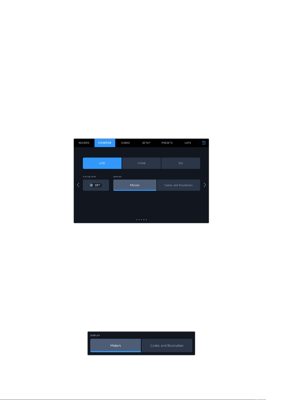
Grid
Tap the ‘grid’ switch in the ‘LCD’, ‘HDMI’ or ‘SDI’ menus to enable a rule of thirds grid for those
outputs. For more information on the rule of thirds grid, see the ‘touchscreen controls’ section.
Safe Area Guide
Tap the ‘safe area’ switch in the ‘LCD’, ‘HDMI’ or ‘SDI’ menus to enable safe area overlay for
those outputs. For more information on the safe area guide, see the ‘touchscreen controls’
section in this manual.
False Color
Tap the ‘false color’ switch in the ‘LCD’, ‘HDMI’ or ‘SDI’ menus to enable false color exposure
assistance for those outputs. For more information, see the ‘menu settings’ section in
this manual.
Monitor Settings 2
The second page of the monitor tab contains the following settings.
LCD, HDMI and SDI
Status Text
This setting can be useful to hide the status text and meters on your LCD touchscreen,
leaving only the information necessary to compose or direct a shot. Tap the ‘status
text’ switch icon to toggle the appearance of status text and meters for your camera’s
LCD touchscreen. Overlays such as frame guides, grids, focus assist and zebra remain
visible, if enabled. Swiping up or down on the LCD touchscreen has the same effect.
LCD
Display
Instead of a histogram and audio meters, your camera can display codec and resolution
information at the left and right bottom edges of the LCD touchscreen. This can be
useful if you prefer to use false color for dialing in exposure, or are recording audio
separately and want to display additional information in the space normally used by the
histogram and audio meter. Simply tap ‘meters’ or ‘codec and resolution’ in the ‘LCD’
menu to select your preferred view.
60Menu Settings

HDMI and SDI
Display Status Text for Cinematographer or Director
The LCD touchscreen displays information such as ISO, white balance, and aperture
that is useful to a camera operator or cinematographer setting up individual shots on
that camera. Your camera’s HDMI or SDI output, however, can also show information
useful to a director or script supervisor who is keeping track of multiple shots
or cameras.
Setting the status text to ‘director’ in the HDMI or SDI monitor settings changes the
status text for that output to show the following information.
FPS
Displays the currently selected frames per second for that camera. If off speed frame
rate is disabled, only the project frame rate is shown. If an off speed frame rate is being
used, the sensor frame rate is shown, followed by the project frame rate.
CAM
Displays the camera index as set in your camera’s slate. For more information, see the
‘slate’ section.
OPERATOR
Identifies the camera operator as set in your camera’s slate. For more information, see
the ‘slate’ section.
DURATION DISPLAY
Displays the duration of the current clip while recording, or the last recorded clip in the
following format: hours:minutes:seconds.
REEL, SCENE, TAKE
Displays the current reel, scene and take. For more information on reels, scenes, takes
and their labeling conventions, refer to the ‘slate’ section.
DYNAMIC RANGE
The bottom left hand corner of the monitor displays the currently applied LUT, if applied
to that output. If no LUT is applied, ‘film’ or ‘video’ dynamic range is displayed.
TIMECODE
The bottom right of the monitor displays your camera’s timecode, in the following
format: hours:minutes:seconds:frames.
61Menu Settings
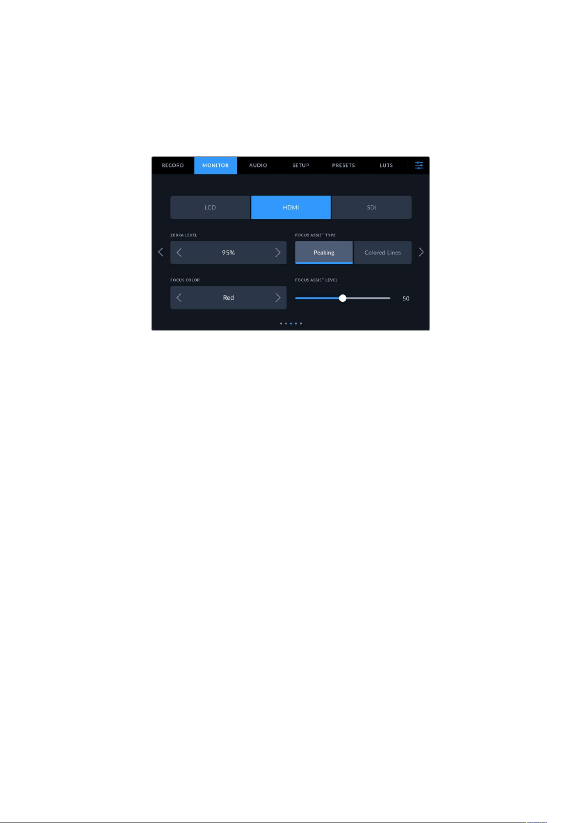
Monitor Settings 3
The third page of the ‘LCD’, ‘HDMI’ and ‘SDI’ monitor tab contains identical settings for each
output. These settings act globally across all three monitoring outputs. For example, if focus
assist is enabled on your Blackmagic Studio Camera’s LCD, HDMI and SDI outputs changing the
‘focus assist type’ from ‘peaking’ to ‘colored lines’ will effect all three outputs.
Zebra Levels
Set the exposure level that zebra appears at by tapping the arrow icons on either side of this
setting. Zebra level is adjustable in five percent steps between 75 and 100 percent exposure.
For more information, see the ‘zebra’ guide in the ‘touchscreen features’ section of this manual.
Focus Assist
Your camera has two focus assist modes, including ‘peak’ and ‘colored lines.’
Peaking
When ‘peaking’ style focus assist is selected, areas of the shot that are in focus are
heavily sharpened on your LCD touchscreen, HDMI or SDI output, but not in the recorded
image itself. This causes focused parts of your shot to ‘pop’ out of the softer background
on screen. As no additional overlays are used, this can be a very intuitive way to tell
when focus is dialed in, especially when the subject you’re focusing on is physically well
separated from other elements in shot.
Colored Lines
When ‘colored lines’ style focus assist is selected, a colored line is superimposed around
the parts of the image that are in focus. This can be a little more intrusive than ‘peaking’
style focus assistance as the lines are drawn over your image, but especially in busy shots
with a lot of visible elements, it can be a precise focus tool.
Focus Color
Use this setting to change the color of focus line overlays when using ‘colored lines’ style focus
assistance. Changing the focus line color can make it easier to tell focus assistance lines apart
from your image. The available options are ‘white,’ ‘red,’ ‘green,’ ‘blue’ and ‘black.’
Focus Assist Level
To set the level of focus assistance for your LCD, HDMI and SDI output, move the slider from
left to right.
62Menu Settings
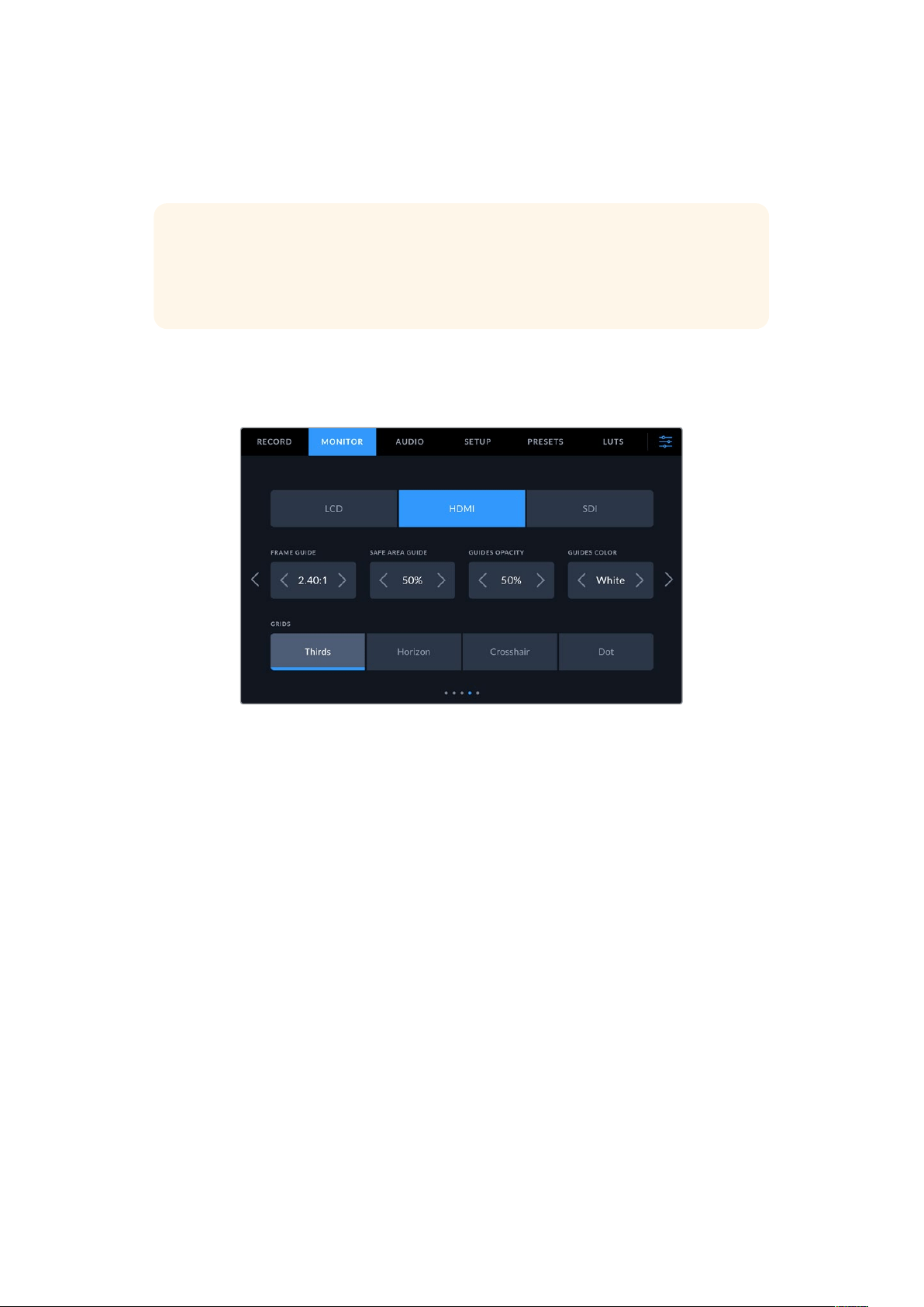
Setting the focus assist intensity level does not affect whether focus assistance is enabled on
your Blackmagic Studio Camera’s LCD, HDMI and SDI output. You need to turn focus assistance
on individually for each output in the LCD, HDMI output and SDI output monitor menus.
TIP The optimum level of focus assistance varies shot by shot. When focusing on
actors, for example, a higher level of focus assistance can help resolve edge detail in
faces. A shot of foliage or brickwork, on the other hand, may show distracting amounts
focus information at higher settings.
Monitor Settings 4
The fourth page of the ‘LCD’, ‘HDMI’ and ‘SDI’ monitor tab contains identical settings for each
output. These settings act globally across all three of your camera’s monitor outputs.
Frame Guides
Tap the left or right arrows in the ‘frame guides’ menu setting to cycle through frame guide
options for all outputs on your camera. The options are detailed in the ‘touchscreen features’
section of this manual, and are also accessible from the LCD monitoring menu in your LCD
touchscreen head up display. It’s worth noting that you can individually select whether
frame guides appear on the LCD touchscreen, HDMI or SDI outputs in their respective
‘monitor’ menus.
Safe Area Guide
To adjust the size of the safe area overlay on your studio camera’s LCD touchscreen, HDMI and
SDI outputs, tap the arrows to the left and right of the percentage displayed in this setting. This
percentage indicates the size of the safe area in relation to the image frame. Most broadcasters
require a 90% safe area.
Guide Opacity
Tap the left or right arrows in the ‘guide opacity’ menu setting to choose the opacity of the
areas blocked out by frame guides on your LCD touchscreen, HDMI and SDI output. The
options are 25%, 50%, 75% and 100%.
Guides Color
Tap the left or right arrows in the ‘guides color’ menu setting to choose a color for the guides.
63Menu Settings
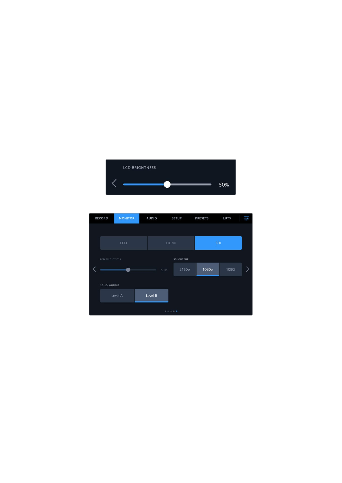
Grids
To set which combination of grids and crosshair you want to display on your camera’s LCD
touchscreen, HDMI and SDI output, tap the ‘thirds’, ‘horizon’, ‘crosshair’ or ‘dot’ options in
this setting.
For more information, see the ‘grids’ guide in the ‘touchscreen features’ section.
Monitor Settings 5
The fifth page of your studio camera’s ‘LCD’, ‘HDMI’ and ‘SDI’ monitor tab contains some
settings that vary depending on the selected output.
LCD only
LCD Brightness
Drag the ‘screen brightness’ slider in the ‘LCD’ menu left or right to adjust the
brightness of your camera’s LCD touchscreen.
HDMI and SDI
HDMI Output
Your studio camera’s HDMI output supports 2160p and 1080p independently of your recording
resolution. The video standard will match your camera’s project frame rate.
The HDMI output can determine the video format and frame rate supported by other HDMI
equipment and sets the output accordingly. For example, if you connect to displays, ATEM
switchers and HyperDeck disk recorders that support HD only, your camera will automatically
set the HDMI output to 1080p.
If your equipment can accept 2160p, you can set the HDMI output to 2160p or 1080p.
SDI Output
The 12G-SDI output supports 2160p, 1080p and 1080i independently of your recording
resolution. When set to 2160p or 1080p the video standard will match your camera’s project
frame rate.
Interlaced HD is available on your SDI output when your project frame rate is set to 50p, 59.94p
or 60p and this will be sent as 1080i50, 59.94 or 60 accordingly.
64Menu Settings
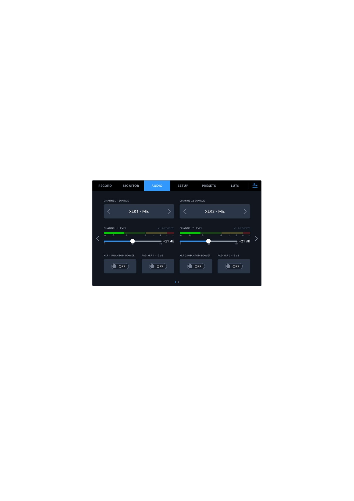
3G-SDI Output
You can change the 3G-SDI output standard to maintain compatibility with equipment that
can only receive level A or level B 3G-SDI video. This option will only appear when you are
operating in 50, 59.94 or 60 frames per second and outputting 1080p. Tap the ‘Level A’ or
‘Level B’ icon to select each standard.
Audio Settings
The ‘audio’ tab lets you adjust the audio input and monitoring settings on your Blackmagic
Studio Camera.
Audio settings for the camera are spread over two pages and divided between channels
1and2. You can map each audio channel to a different source, as well as adjusting various
settings such as level control.
Audio Settings Page 1
The first page of the ‘audio’ tab contains the following settings.
Channel Source
Use the ‘channel 1 source’ and ‘channel 2 source’ buttons to select your audio source for each
audio channel. Below is a description of each channel source setting.
Camera Left or Right
Records from your camera’s internal microphones.
Camera Mono
Creates a single audio channel from your Blackmagic Studio Camera’s built in microphone’s
left and right channels.
XLR Mic
Records mic level audio from equipment connected to your camera’s XLR input. Ifphantom
power is enabled and you have the XLR input set to ‘mic’ you’ll also see a‘+48V’ indicator
here. It is also important to ensure that the 48V switch gets turned ‘off’ when you
disconnect your phantom powered microphone.
XLR Line
Sets your camera to record line level audio from equipment connected to the XLR input.
3.5mm Left – Line
Uses only the left channel of the 3.5mm input as line level audio.
3.5mm Right – Line
Uses only the right channel of the 3.5mm input as line level audio.
65Menu Settings

3.5mm Mono – Line
Creates a mono mix of the left and right channel from the 3.5mm input as line level audio.
3.5mm Left – Mic
Uses only the left channel of the 3.5mm input as mic level audio.
3.5mm Right – Mic
Uses only the right channel of the 3.5mm input as mic level audio.
3.5mm Mono – Mic
Creates a mono mix of the left and right channel from the 3.5mm input as mic level audio.
None
Disables your audio channel.
NOTE When selecting the 3.5mm input as an audio source, the channel 1 and
channel 2 sources both need to be line level or mic level. This means that if you
select ‘3.5mmleft - line’ as your channel 1 source, the available options for the 3.5mm
input on channel 2 will all be line level: ‘3.5mm left - line’, ‘3.5mm right - line’ and
‘3.5mmmono - line’. The mic level options will be grayed out.
Channel 1/2 Level
Use these sliders to adjust the recording levels of your chosen channel 1 and 2 sources.
Audio meters are included with each slider to help you set the correct audio level. To achieve
optimum audio quality, ensure your audio levels do not reach 0 dBFS. This is the maximum level
that your camera can record, meaning that any audio that exceeds this level will be clipped,
resulting in distortion.
XLR Phantom Power
The XLR inputs can provide 48V phantom power so you can use microphones that aren’t self
powered. When your camera is set to ‘XLR’ audio input, simply tap the ‘phantom power’ switch
icon to enable phantom power. Phantom power switches are provided for each XLR input.
NOTE It is standard practice to plug in your XLR cable before switching phantom
power on. It is also important to switch phantom power to ‘off’ when you no longer
have a phantom powered microphone connected. Connecting equipment that
doesn’t require phantom power when still in phantom power mode can damage your
equipment, as the camera outputs a charge when in this mode. Phantom power can
also take quite a while to discharge after switching it off. Please be aware that you
should wait for ten seconds when switching off phantom power before plugging in any
other microphones or XLR audio equipment.
Pad XLR -13dB
The -13dB pad option gives you added control to further reduce the input gain levels on XLR
audio inputs when shooting in a loud environment even after your input levels are already
turned down.
66Menu Settings
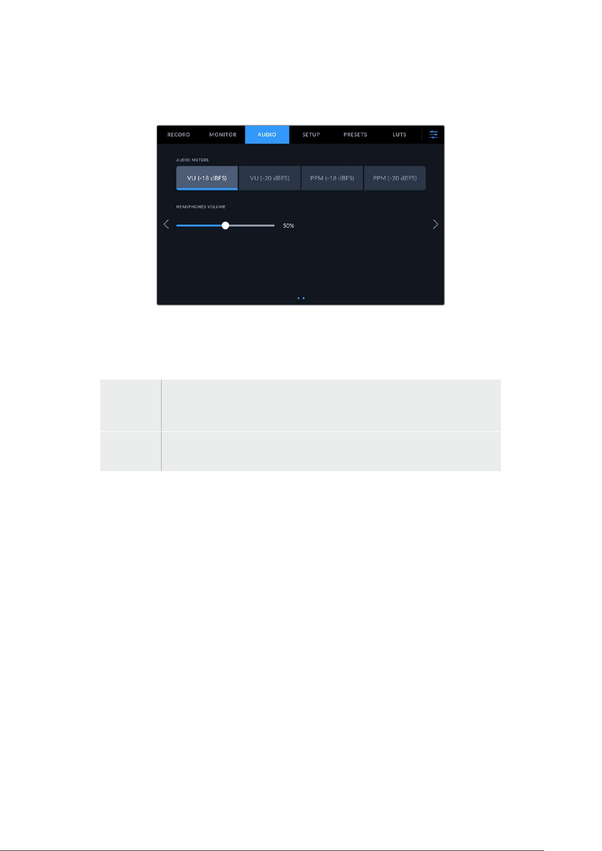
Audio Settings Page 2
The second page of the ‘audio’ tab contains the following settings.
Audio Meters
You can select from VU or PPM meter types. While the VU meter has now become
standardized, PPM and loudness meters provide scaling systems and measurements for
perceived loudness.
VU This meter averages out short peaks and troughs in your audio signal. It’s mostly
used to monitor peaks in a signal, however, because of its averaging capability it can
also be used to monitor the perceived loudness of your audio.
PPM This meter displays a ‘peak hold’ feature that momentarily holds the signal peaks,
and a slow fall back so you can easily see where your audio is peaking.
Headphones Volume
This slider adjusts the output levels for headphones and headsets connected to the 3.5mm or
5pin XLR headset jacks. Move the audio slider left or right to adjust levels.
Setup Settings
The ‘setup’ tab contains your Blackmagic Studio Camera’s identification settings, software
version, function button settings and other camera settings not directly linked to recording or
monitoring. You can cycle through the menu pages by tapping the arrows at the edge of the
LCD touchscreen, or swiping left or right.
67Menu Settings
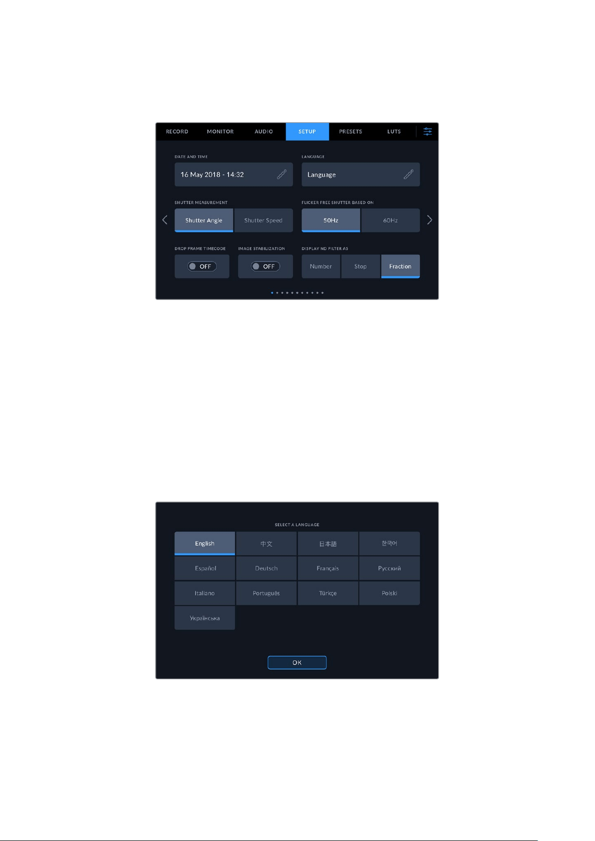
Setup Settings Page 1
The first page of your camera’s ‘setup’ tab contains the following settings.
Date and Time
Set your camera’s date and time by tapping the ‘date and time’ setting. The date format is year,
month, day and the time format is 24 hour. Date and time are also used for time of day timecode
if an external timecode source is not connected.
Language
Blackmagic Studio Cameras support 13 popular languages: English, Chinese, Japanese, Korean,
Spanish, German, French, Russian, Italian, Portuguese, Turkish, Polish and Ukrainian.
The ‘select language’ page will appear on initial start up and after you update the camera’s
internal software.
To select your language:
1 Tap on the ’language’ in the list
2 Select ‘update’ to return to the setup menu.
68Menu Settings

Shutter Measurement
Select whether to display shutter information as ‘shutter angle’ or ‘shutter speed’. When using
shutter angle, the shutter conforms to the frame rate. When using shutter speed, the shutter is
given an absolute, real time value and isn’t connected to your frame rate.
For example, when using a shutter speed of 1/48th of a second, motion blur will remain
consistent regardless of the frame rate as the measurement is always the same in real time.
Alternatively, a shutter angle of 180 degrees is directly applied to each frame, and therefore
influenced by the amount of frames recorded each second. This means motion blur will vary
based on the frame rate you are using.
It’s worth mentioning the minimum shutter speed value corresponds to the frame rate. This
means 1/24th of a second is the minimum available shutter speed when shooting at 24p and
1/50th is the minimum shutter speed available for 50p.
Flicker Free Shutter based On
Use this setting to change the mains power frequency your camera uses to calculate flicker free
shutter settings.
When shooting under lights, your shutter can affect the visibility of flicker. Your Blackmagic
Studio Camera automatically calculates a flicker free shutter value for current frame rate and
suggests up to three shutter values. Shutter values are affected by the frequency of local
mains power supply used to drive those lights. In most PAL countries, the frequency is 50Hz,
while NTSC countries typically use 60Hz power. Tap ‘50Hz’ or ‘60Hz’ to set the frequency for
your region.
Lens Stabilization
Use the ‘lens stabilization’ option to enable or disable image stabilization on lenses without a
physical switch.
Drop Frame Timecode
Use the ‘drop frame timecode’ option to use drop frame timecode when using NTSC project
frame rates of 29.97 and 59.94. Drop frame timecode skips a small number of frames from the
timecode at set intervals. This keeps your project timecode accurate despite each second not
containing a whole number of frames at NTSC frame rates.
Display ND Filter As
On Blackmagic Studio Camera 6K Pro, you can adjust how the ND filter indicator displays your
ND filter setting. Each option corresponds to a different camera convention. Cinematographers
typically use ND.number notation, while those familiar with DSLRs or broadcast cameras may
prefer this information in f-stop format, or as a fraction of available light. These options are
available here as ‘number,’ ‘stop,’ and ‘fraction,’ respectively.
69Menu Settings
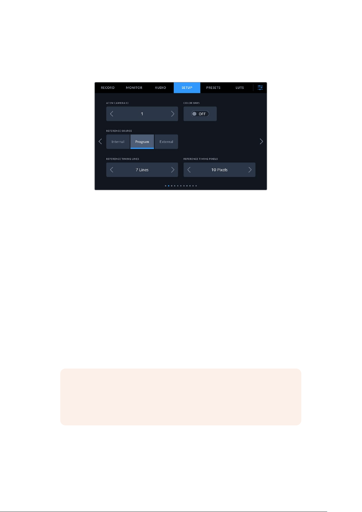
Setup Settings Page 2 on Blackmagic Studio Camera ‘Pro’ models
The second page of the ‘setup’ tab contains the following settings on Blackmagic Studio
Camera 4K Pro models and 6K Pro.
ATEM Camera ID
If you’re using more than one Blackmagic Studio Camera ‘Pro’ model with an ATEM Switcher
and want your cameras to receive tally signals from the switcher, you’ll need to set their ATEM
camera ID numbers. This ensures the switcher sends the tally signal to the correct cameras.
The camera ID number can be set to a value of 1-99 by tapping the left or right buttons. The
default setting is 1.
Color Bars
Outputting color bars rather than a preview image can be useful when connecting your Studio
Camera 4K Pro or 6K Pro model to a switcher or external monitor. The appearance of your
studio camera’s color bars onyour switcher or monitor confirms the connection, and you can
perform basic monitor calibration based on the colors of the bars. To turn on color bars for all
outputs on Blackmagic Studio Camera 4K Pro or 6K Pro models, including the LCD touchscreen,
simply tap the ‘color bars’ switch icon.
Reference Source
This setting is used to select the reference source. Blackmagic Studio Camera 4K Pro and 6K
Pro models can lock to an internal or external reference source, or to the reference signal in
the program input from an ATEM switcher. If you are using your Studio Camera with an ATEM
Switcher set your reference source to ‘program’. If the switcher and all connected cameras are
set to an external reference source then setting this to ‘external’ and using your ‘Pro’ Studio
Camera with a Blackmagic Studio Converter will allow you to receive an analog reference input.
NOTE When you are setting your reference source for Blackmagic Studio Camera 4K
Pro and 6KPro models, you may experience a small dropout on your camera’s outputs
when switching between your reference sources. This is because the camera is
adjusting itsreferencing timing to match that of the external source. For this reason it is
important not to change this setting during a production and only while setting up.
70Menu Settings
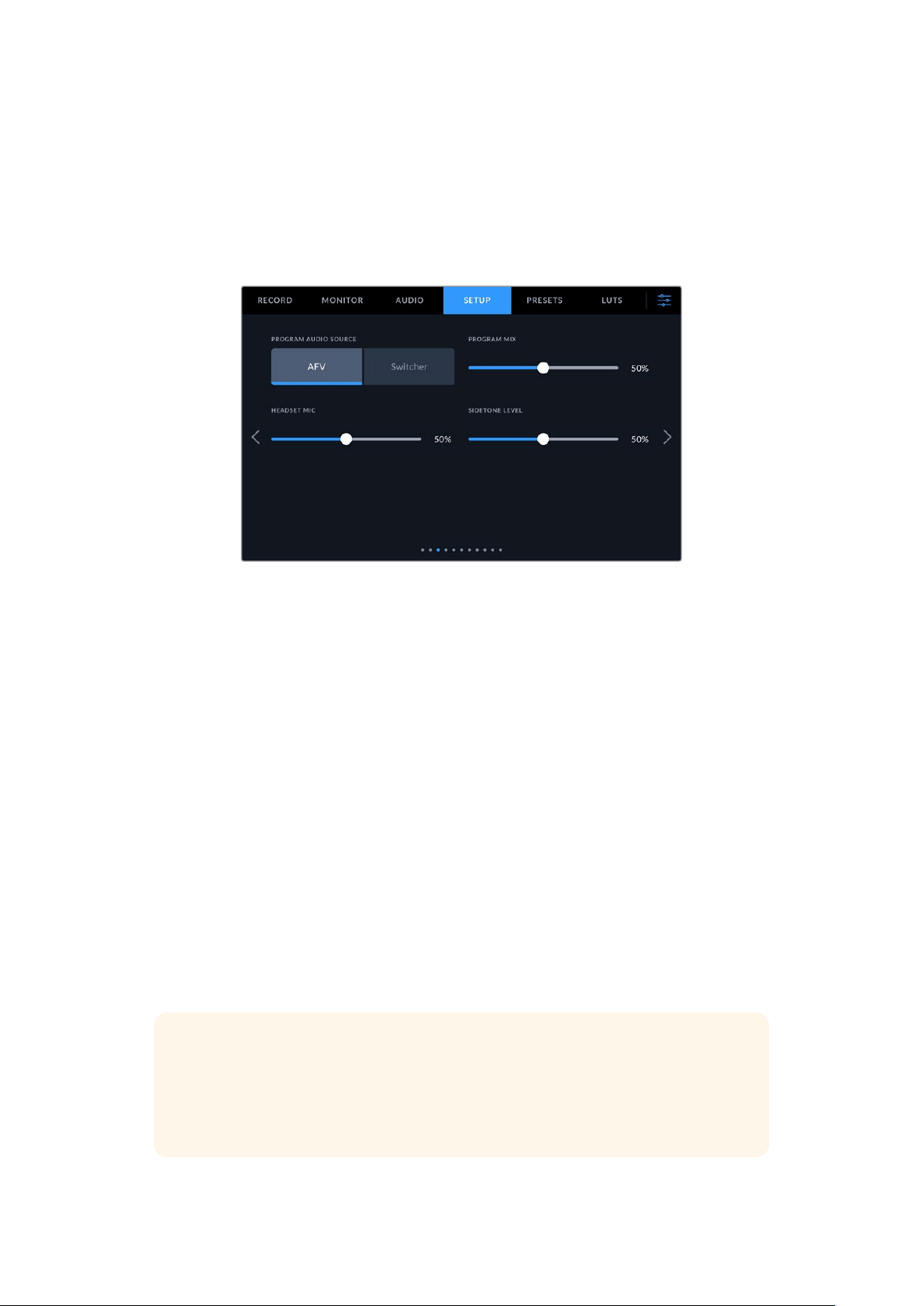
Reference Timing
These settings allow you to manually adjust the reference timing on a line or pixel basis. Simply
tap the arrow icons on either side of the ‘lines’ and ‘pixels’ settings to make adjustments.
Setup Settings Page 3 on Blackmagic Studio Camera ‘Pro’ models
The third page of the ‘setup’ tab contains the following settings for Blackmagic Studio Camera
4K Pro and 6K Pro models.
Program Audio Source
When connected to an ATEM switcher, setting ‘program audio source’ to ‘switcher’ prioritizes
the program return audio as your input source to be mixed with talkback when monitoring using
headphones or a headset. This is useful when you are not feeding the switcher audio from your
camera but you still want to listen to the program feed from the switcher via the ‘SDI in’ port.
Setting ‘program audio source’ to ‘AFV’, or audio follows video, prioritizes audio that is being
displayed on your LCD. That means if the camera’s LCD is displaying what the camera is seeing,
you will hear that audio source, but if you have engaged the program return feed, your audio
source will be coming from the program audio feed.
Program Mix
This setting changes the balance of camera sound to talkback sound. The headphones
will output audio following what is displayed on the LCD. For instance, if you are in camera
view, camera audio is heard. If you are in program view, program audio is heard. The default
setting is 50%.
Headset Mic
Move this volume slider left or right to increase or decrease audio microphone input levels.
Thedefault setting is 50%.
Sidetone Level
Adjust this slider to set the volume of your own voice mic in your headset.
TIP Blackmagic Studio Camera ‘Pro’ models have a powerful talkback mic preamp so
care should be taken when adjusting your mic gain or sidetone levels with 3.5mm mini
jack consumer earbuds or headsets. Often these are not very well electrically shielded
which can cause crosstalk. If you do encounter this then setting your sidetone very low
will cancel out the feedback being caused by your headset.
71Menu Settings
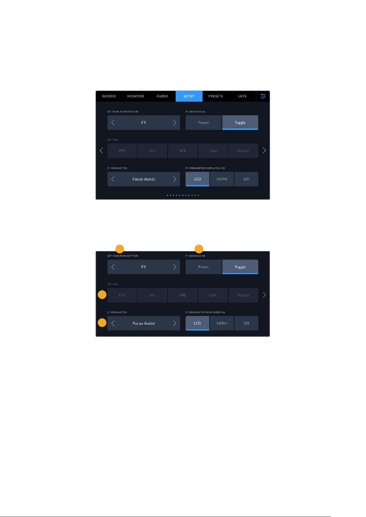
Setup Settings Pages 4 and 2
The fourth page of the ‘setup’ tab on Blackmagic Studio Camera 4K Pro and 6K Pro models
contains the following settings. These settings are on the second page for Blackmagic Studio
Camera 4K Plus.
Set Function Button
Next to your studio camera’s LCD touchscreen, you’ll notice three function buttons, ‘F1’, ‘F2’
and ‘F3’. These are mappable to frequently used features and are quickly accessible when
operating your camera live and want to avoid using the touchscreen.
1
3
4
2
1 Button 2 Behavior 3 Setting 4 Parameter
Function Button Behaves as Preset or Toggle
Once you have selected the function button you want to map, you can select a behavior.
The available options are:
Preset
When set to this behavior, pressing a function button will recall a combination of a setting
and a parameter.
To set a preset, select the setting you want to use from the ‘setting’ menu, and adjust that
setting by tapping the arrow icons on either side of the ‘parameter’ menu.
For example, to set the F1 button to recall a preset white balance, use the ‘set function
button’ arrows to select ‘F1’, select the ‘preset’ behavior, tap the ‘WB’ setting, and tap the
arrows on either side of the ‘parameter’ menu until you get to WB ‘5600K’ and Tint ’10’
72Menu Settings
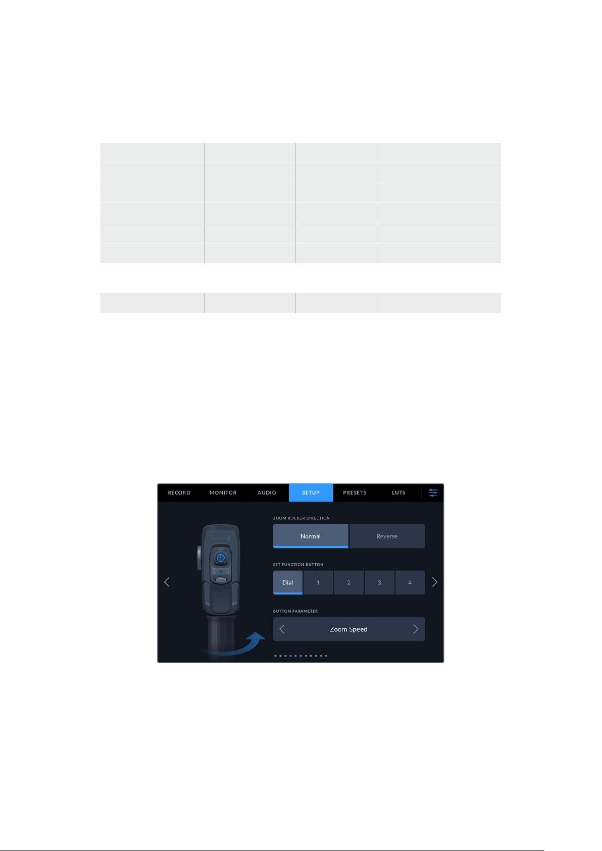
Toggle
When set to this behavior, pressing a function button will toggle a particular setting on or
off. The ‘setting’ menu is grayed out in this mode. Instead, tap the left or right arrows in the
parameter menu to scroll through the available options, such as:
focus zoom focus iris record
auto white balance program return OIS optical image stabilization
push to talk still call clean feed
status text display LUT frame guides focus assist
false color zebra grid safe area guide
off speed recording color bars stream none
On Blackmagic Studio Camera 6K Pro the additional options are:
ND up ND down ND toggle
Using the ‘toggle’ behavior also lets you select the output this setting applies to. Simply tap any
combination of ‘LCD,’ ‘HDMI’ and ‘SDI’ to select. Ifthe output for an option is not available, such
as ‘focus zoom’, the ‘HDMI’, and ‘SDI’ settings are disabled.
Setup Settings Pages 5 and 3
The fifth page of the ‘setup’ tab on Blackmagic Studio Camera 4K Pro and 6K Pro models and
the third page on Studio Camera 4K Plus contains settings to configure the optional Blackmagic
Zoom Demand. These settings are only active when you have Blackmagic Zoom Demand
attached to your camera.
For information on attaching and using Blackmagic Zoom Demand, refer to the ‘Blackmagic
Zoom and Focus Demand’ section.
73Menu Settings
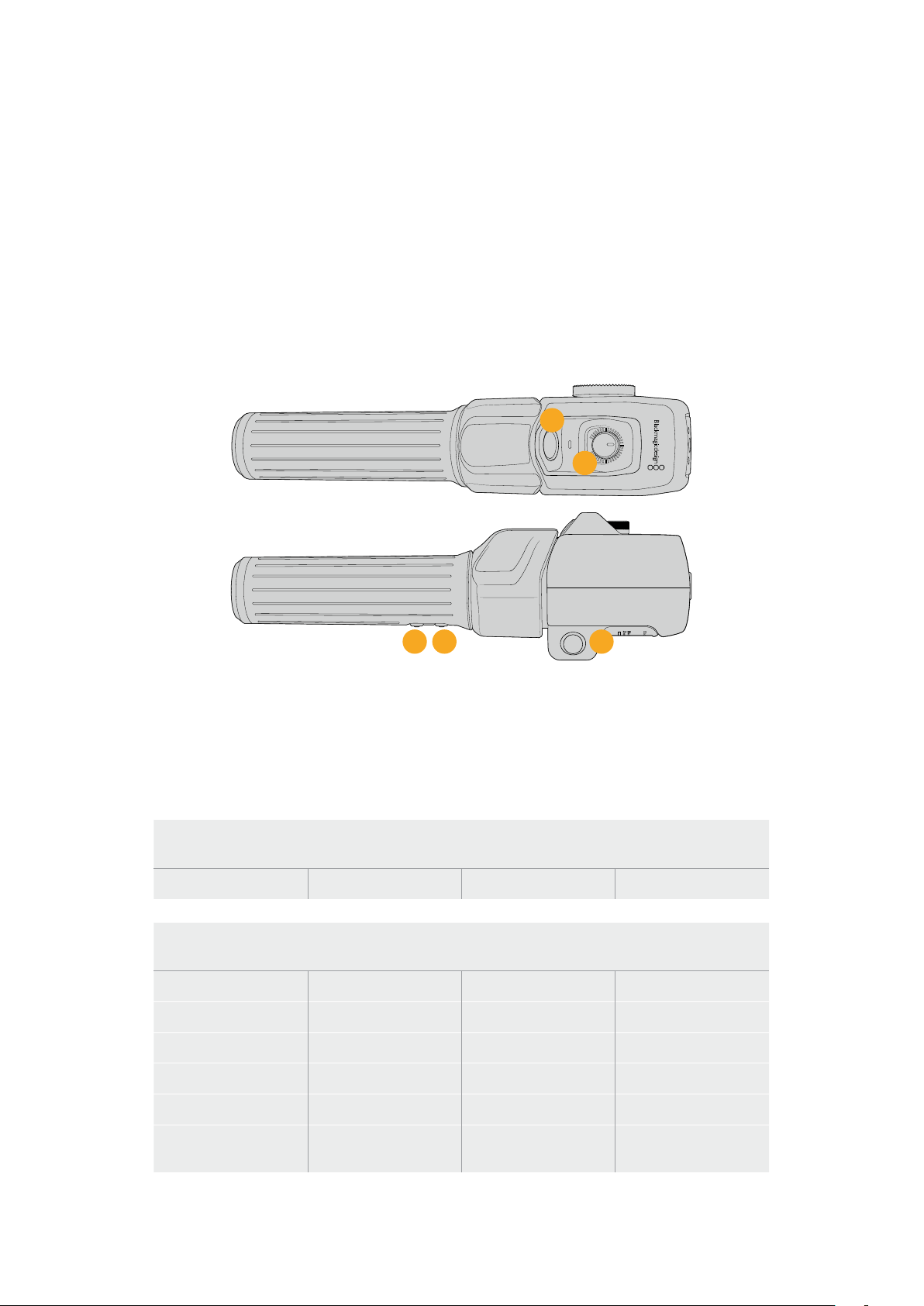
Zoom Rocker Direction
You can change the direction of the focus wheel on focus demand by selection either ‘normal’
or ‘reverse’.
Normal
The default zoom rocker direction. Push the zoom rocker to the right to zoom in and to the
left to zoom out.
Reverse
When the zoom rocker direction is set to ‘reverse’ push the zoom rocker to the left to zoom
in and to the right to zoom out.
Blackmagic Zoom Demand has four zoom function buttons and a speed dial that you can map
to different functions.
2
3
4
SPEED
1
5
1 Zoom F1 2 Zoom F2 3 Zoom F3 4 Zoom F4 5 Speed Dial
To assign a different function to the speed dial or one of the zoom buttons choose ‘dial’ or a
button number from the ‘set function button’ menu. Next, choose a function by tapping the
arrow icons on either side of the ‘button parameter’ menu.
Depending on your studio camera model, dial and function button parameter options include:
Speed Dial
Zoom speed headphone level iris adjustment focus adjustment
Zoom Buttons 1 - 4
Record Quick Zoom Focus Zoom Frame Guides
Status Text Color Bars Focus, Iris Auto White Balance
Push To Talk Program Return OIS Call
Zoom Point A Zoom Point B Zoom Point C Zoom Point D
Focus Point A Focus Point B Focus Point C Focus Point D
Zoom and
Focus Point A
Zoom and
Focus Point B
Zoom and
Focus Point C
Zoom and
Focus Point D
74Menu Settings
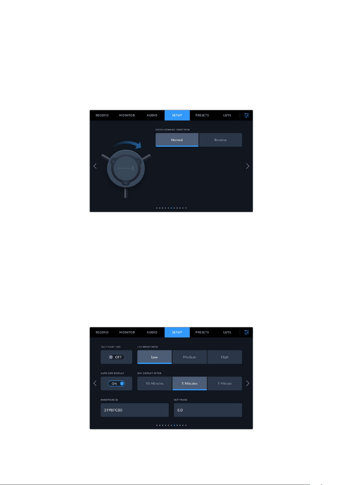
Setup Settings Pages 6 and 4
The sixth page of the ‘setup’ tab on Blackmagic Studio Camera 4K Pro and 6K Pro models
and the fourth page on Studio Camera 4K Plus contains settings to configure the optional
Blackmagic Zoom Demand. These settings are only active when you have Blackmagic Focus
Demand attached to your camera.
For more information on attaching and using Blackmagic Focus Demand, refer to the
‘Blackmagic Zoom and Focus Demand’ section later in this manual.
Focus Demand Direction
You can change the direction of the focus wheel on focus demand by selection either ‘normal’
or ‘reverse’.
Normal
Turn the focus wheel clockwise to focus on subjects closer to the lens and
counterclockwise for subjects further away.
Reverse
Turn the focus wheel counterclockwise to focus on subjects closer to the lens and
clockwise for subjects further away.
Setup Settings Pages 7 and 5
The seventh page of the ‘setup’ tab on Blackmagic Studio Camera 4K Pro and 6K Pro models
contain the following settings. This is the fifth page for Blackmagic Studio Camera 4K Plus.
75Menu Settings
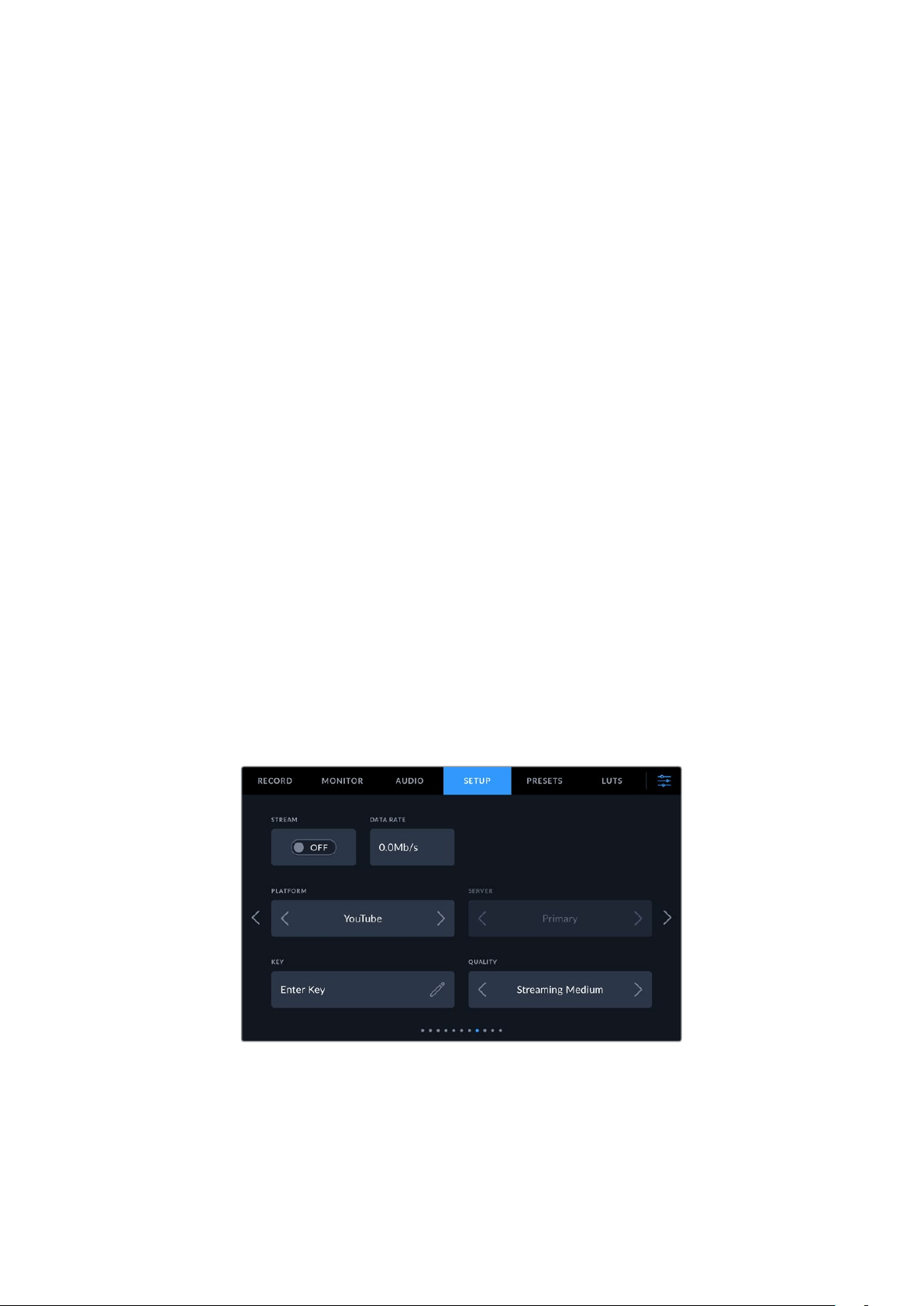
Tally Light LED
In some shooting environments, for example a dimly lit location or an intimate theater
performance, you may want to disable the tally light on your camera. To disable the tally light,
simply set ‘tally light LED’ to ‘off’. When disabling the tally LED, this will also disable the back
light LEDs in all buttons and status lights.
LED Brightness
To set the brightness of the tally light LED, tap ‘low,’ ‘medium,’ or ‘high’. This will also change the
brightness of all back light LEDs on buttons and status lights.
Auto Dim Display
Your Blackmagic Studio Camera has an option to automatically turn down the brightness of the
LCD touchscreen during periods of inactivity. Select an option for ‘dim display after’ to set how
long to wait before dimming the display. The next time you interact with your camera or lens,
the screen will return to its normal brightness level.
Hardware ID
The ‘hardware ID’ indicator displays an 8 character identifier for your Blackmagic Studio
Camera. This is unique to each camera. A longer, 32 character version of this ID is also included
in the metadata for Blackmagic RAW. This can be useful for identifying which footage came
from a particular camera.
Software
Displays the version number of currently installed software. Seethe ‘Blackmagic Camera Setup
Utility’ section for more information on updating software.
Setup Settings Page 8 on Blackmagic Studio Camera 4K Pro G2
and6KProModels
The eighth page of Blackmagic Studio Camera 4K Pro G2 and 6K Pro’s ‘setup’ tab contains
settings that allow you to set your camera’s streaming options.
For more information on setting up streaming, refer to the ‘streaming video’ section later in
this manual.
Stream
Use the stream switch to toggle your stream on or off.
Data Rate
Displays the data rate of the stream during streaming.
76Menu Settings
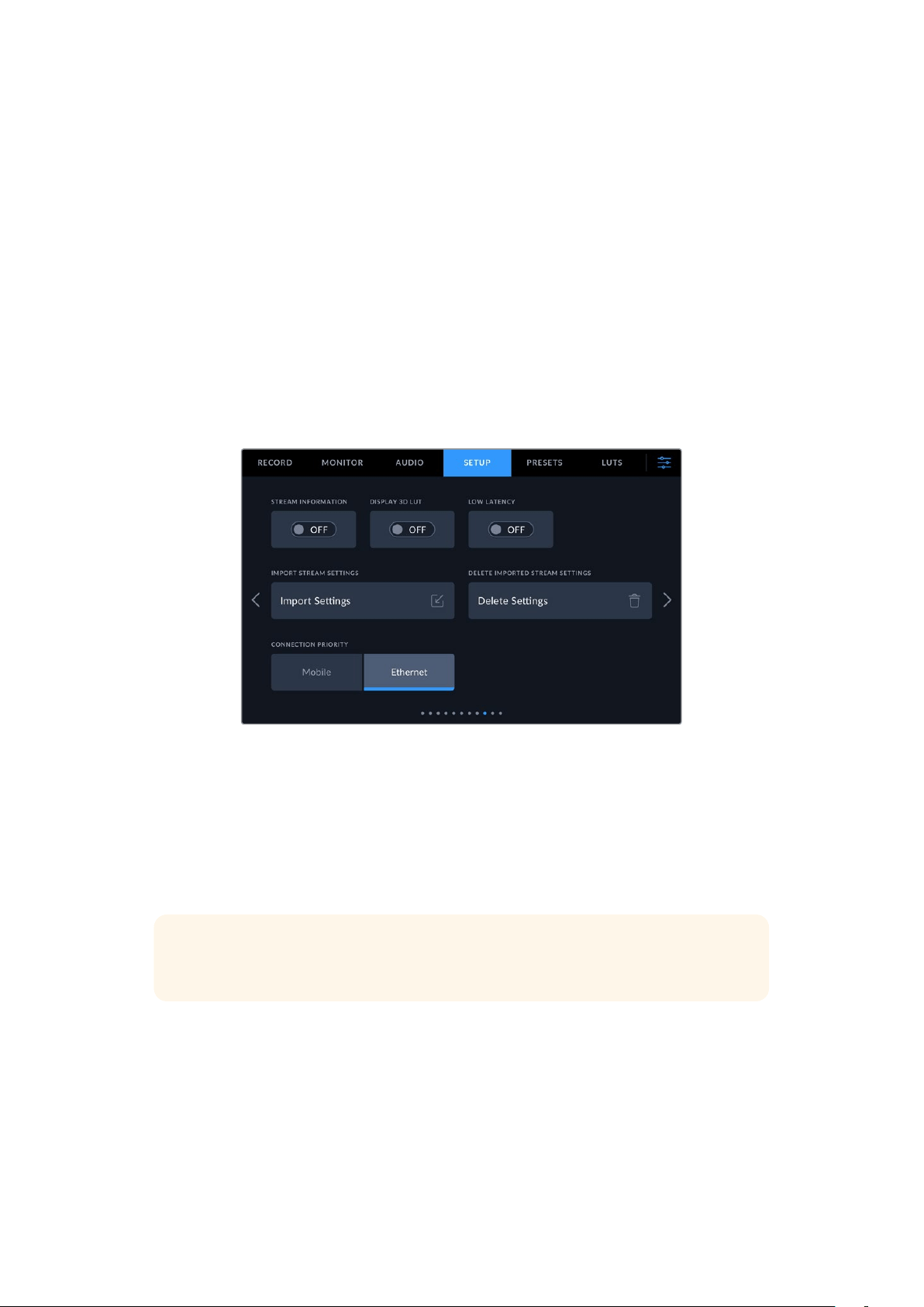
Platform
Select your desired streaming platform. Options include YouTube, Twitter and Twitch.
Server
Use the arrow buttons to choose a server, these options will change depending on your
streaming platform.
Key
Tap the pencil icon to enter a stream key for your streaming platform.
Quality
Use the arrow buttons to select a streaming quality.
Setup Settings Page 9 on Blackmagic Studio Camera 6K Pro
The ninth page of your Studio Camera 6K Pro’s ‘setup’ tab contains settings that relate to your
camera’s streaming options.
Stream Information
Toggle the ‘stream information’ switch to ‘on’ to display information on your camera’s status
display. This will be viewable on the LCD when status text is turned on. The information includes
the connection being used for streaming, for example Ethernet or a smartphone, a duration
counter that shows the duration of your stream and a data rate using megabits per second.
Display 3D LUT
Toggle this setting to ‘on’ if you want to apply a 3D LUT to your stream.
TIP Switching the ‘display 3D LUT’ setting to ‘on’ will only apply a LUT to the direct
stream output.
If you are simultaneously recording to Blackmagic RAW while streaming, you can use the LUT
options in the record menu to add a LUT to your files, or the monitor settings to add a LUT on
the LCD, HDMI or SDI outputs. Refer to the ‘record settings’ section for more information.
Low Latency
Setting low latency to ‘on’ will ensure that there is minimum delay between what is happening
live and what is being viewed by the audience. Setting it to ‘off’ gives you more buffering so is a
more stable stream if you have an Internet connection that may be subject to drop outs or poor
connection.
77Menu Settings
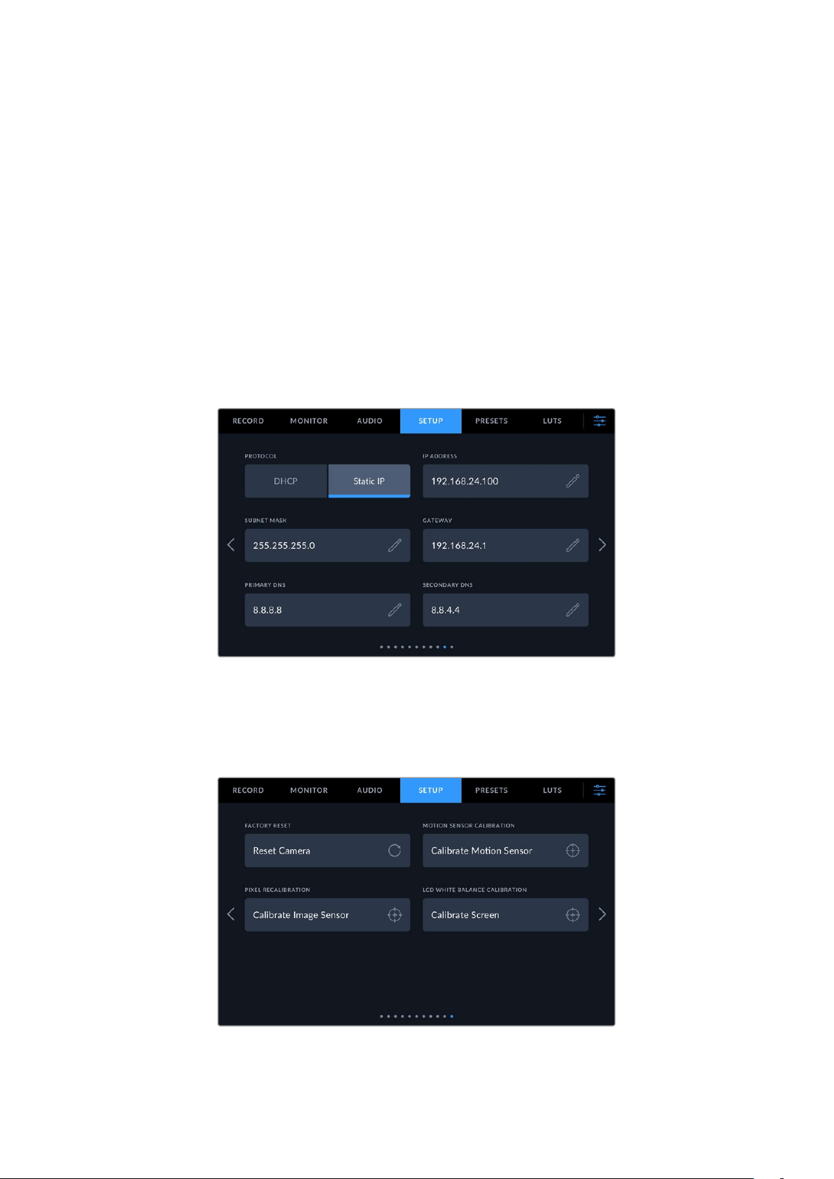
Import Stream Settings
Tap the ‘import stream settings’ button to import an XML setup file that has been created so
your camera can find an ATEM Streaming Bridge on the Internet. For more information on
importing an XML setup file, refer to the ‘streaming video’ section later in this manual.
Delete Stream Settings
Press this button to delete your camera’s imported streaming settings. You will be asked to
confirm your selection.
Connection Priority
When Ethernet and a mobile phone are both connected to your Blackmagic Studio Camera
6KPro, this setting lets you choose which connection will be used for streaming.
Setup Settings Pages 10 and 6
The tenth page of the ‘setup’ tab on Blackmagic Studio Camera 4K Pro and 6K Pro models
contains the following settings. This is the sixth page for Blackmagic Studio Camera 4K Plus.
You can connect to a network using a DHCP or a static IP address
Setup Settings Pages 11 and 7
The eleventh page of the ‘setup’ tab on Blackmagic Studio Camera 4K Pro G2 and 6K Pro
contains the following settings. This is the seventh page on Blackmagic Studio Camera 4K Plus.
78Menu Settings
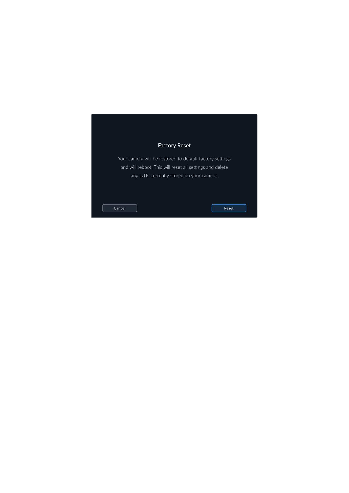
Factory Reset
To reset the camera to its default factory settings, tap the ‘reset camera’ button. On the
confirmation page, tap ‘reset’ to confirm this action. Your camera erases any stored LUTs and
presets, and resets all settings. It is a good practice to export your presets to a USB flash
drive as a backup before performing a factory reset. After a factory reset, you can restore your
presets quickly by importing them from the flash drive. It is important to note that a factory reset
also resets the horizon meter, so you should recalibrate the motion sensor after a factory reset
to help ensure its accuracy.
When selecting ‘reset’ you will be prompted to confirm your action
Motion Sensor Calibration
To calibrate the horizon meter, place your camera on a surface you know is level and tap
the ‘calibrate motion sensor’ button. It is essential that you keep the camera stable during
calibration. The process takes approximately five seconds to complete.
Pixel Recalibration
The CMOS sensor used in your Blackmagic Studio Camera is made up of millions of pixels that
respond to light. As a result, they become more visible and become what is known commonly
as hot pixels. All camera sensors, regardless of manufacturer, will develop this variation in pixel
brightness over time.
To solve this, your studio camera has a built in recalibration feature that you can run if you see
any pixels that are brighter than others.
To perform the pixel racalibration process:
1 Attach the lens cap.
2 Tap the ‘calibrate image sensor’ button
3 Tap ‘calibrate’ to confirm your choice.
The process takes approximately one minute to complete. When complete, tap ‘OK’.
LCD White Balance Calibration
To perform LCD white balance calibration, adjust the ‘LCD temperature’ and ‘LCD tint’ controls
so that the two reference patches look neutral. After you change the settings, you can use the
‘reset’ button to return the controls to the factory calibration. The ‘restore’ button brings back
your new settings, which helps you compare the appearance before and after calibration. When
the LCD shows an accurate white balance, save your settings.
79Menu Settings
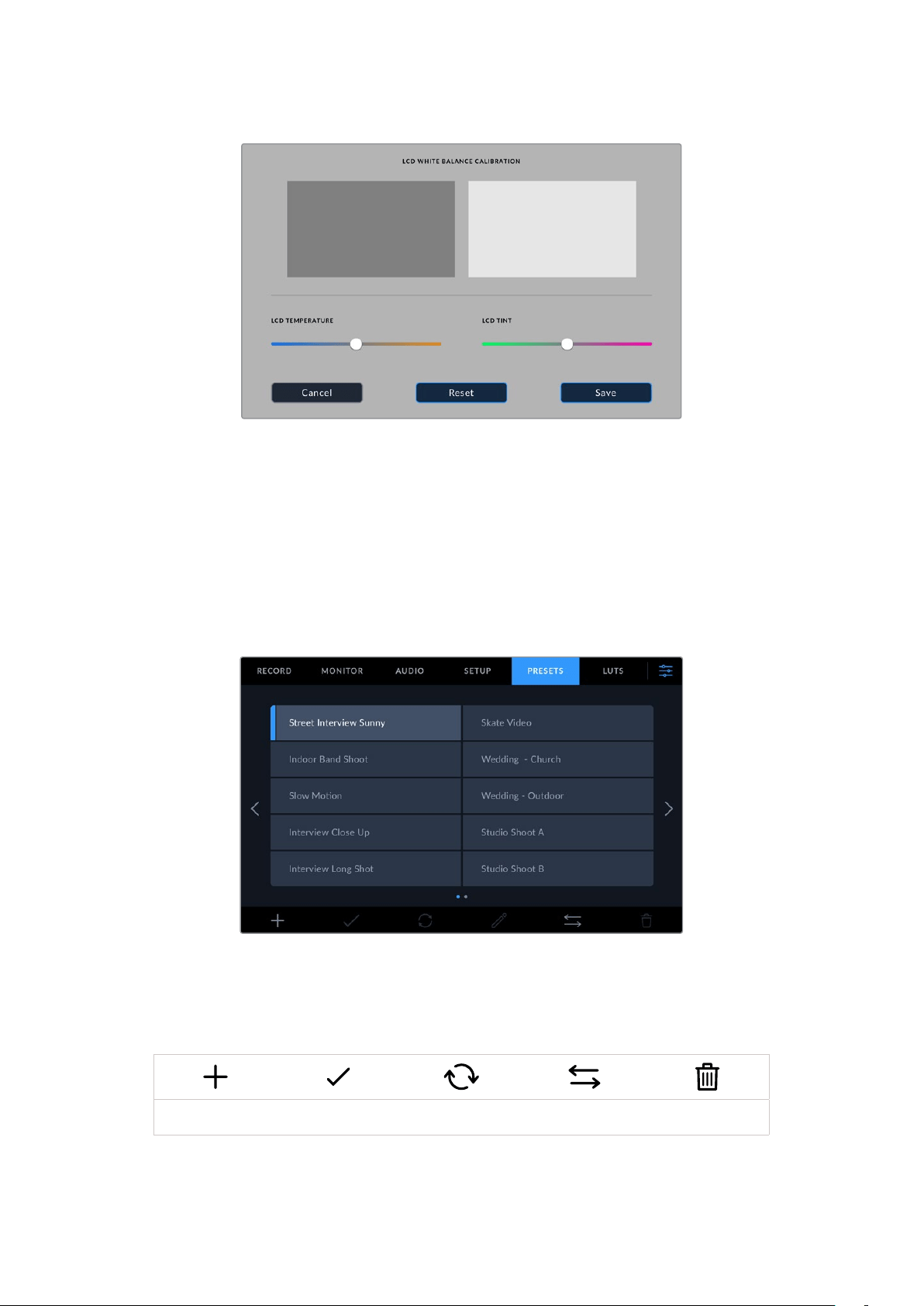
Presets
The ‘presets’ tab lets you save and recall a complete collection of settings for your Blackmagic
Studio Camera. This is very useful when one camera is used for multiple projects. For example,
you may use your camera for a variety of different shoots with very different settings between
types of projects. Your camera’s ‘presets’ function lets you save the setup for a particular
project or type of shoot and come back to it quickly and easily when required.
You can also import and export presets. Simply set up one Blackmagic Studio Camera to suit
your project, then export that preset for all the other Blackmagic Studio Cameras on your
production.
The presets tab allows you to quickly switch between settings that you have saved
Preset buttons
The button icons along the bottom of your studio camera’s ‘preset’ menu correspond with the
following functions.
Add Load Update Manage Delete
80Menu Settings
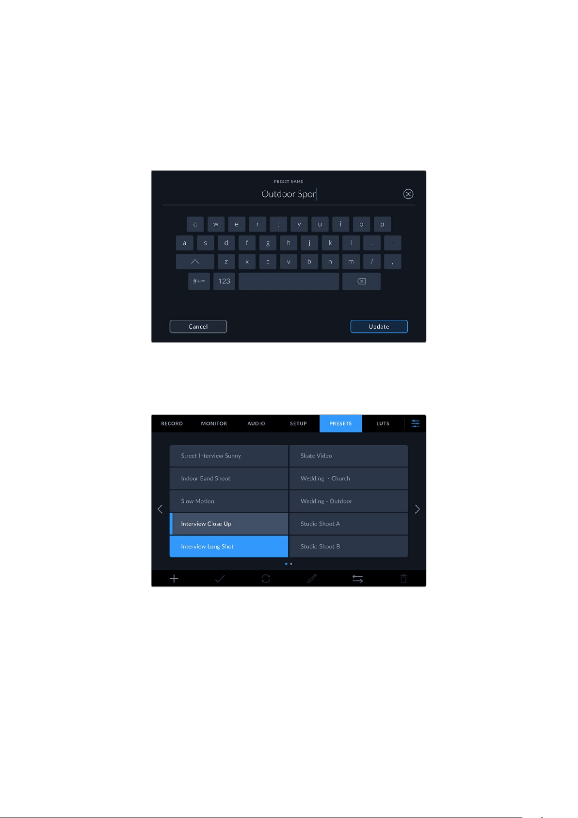
Saving and loading presets
To create a new preset, tap the ‘add’ icon. This opens a touch keyboard on your LCD where
you can name your preset. Enter a name and tap ‘update’ to save all of your current settings to
that preset.
If your camera already has a preset loaded with the same name, you can choose to overwrite
the existing preset or keep both.
Enter a name for your preset by tapping the ‘add’ icon inthepreset tab and using
the touch keyboard
Once you have a preset saved, tap its name in the preset menu to select it. To load a preset, tap
the ‘load’ icon.
Selected presets will appear solid blue, whilecurrently loaded
presets have a blue line on the left of their icon.
You can update a preset by tapping the ‘update’ icon. This will bring up a prompt asking
you if you want to update the preset with your studio camera’s current settings. Tap ‘update’
to confirm.
Importing Presets
To import a preset from a USB-C flash disk, tap the ‘manage’ icon at the bottom of the
‘presets’ menu. Tap ‘import preset’ from the ‘manage preset’ options and select the USB-C
disk that contains the preset you want to import. Tap the ‘import’ button at the bottom of the
touchscreen.
81Menu Settings
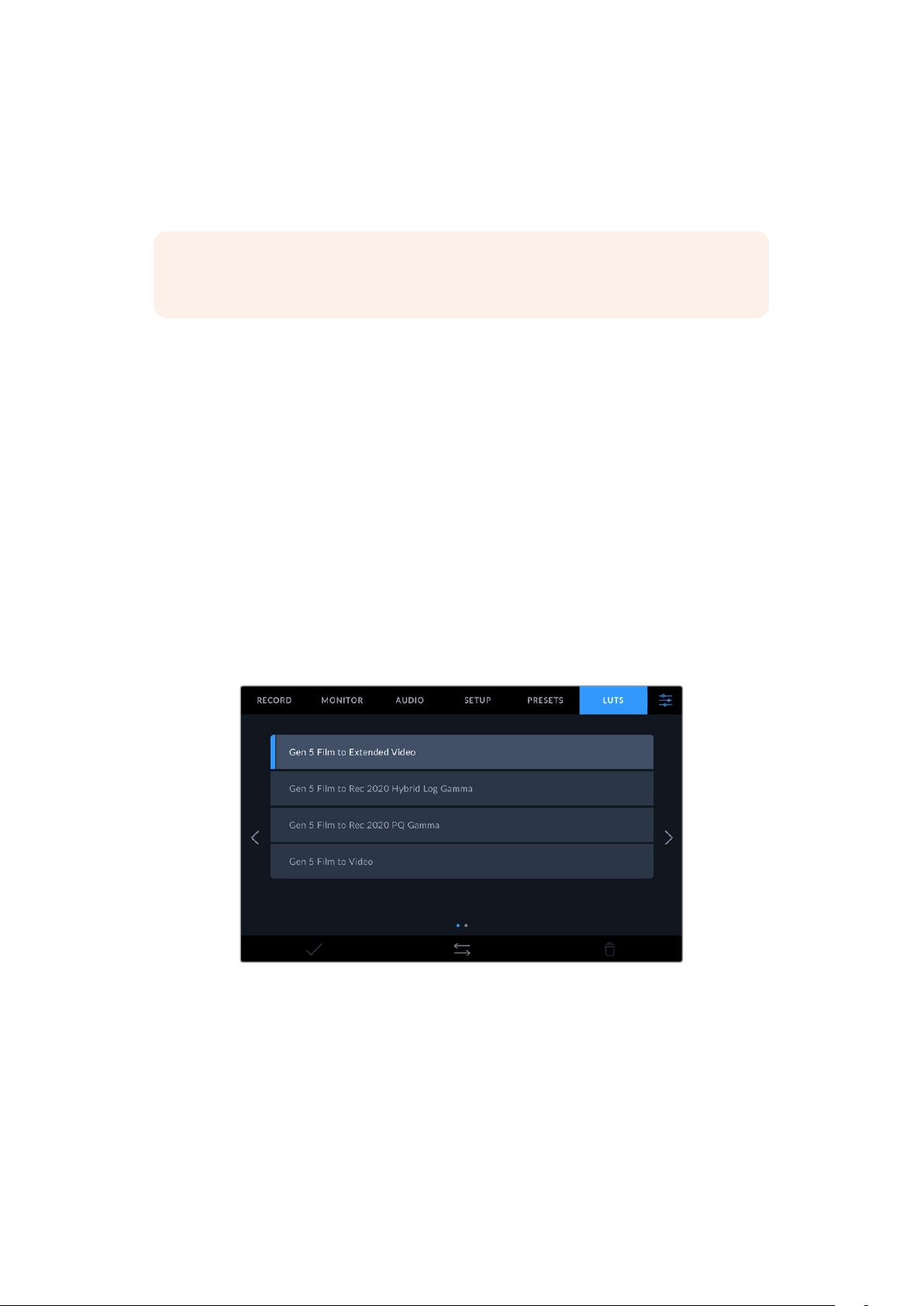
Your camera searches the root directory and ‘presets’ folder on your selected media, and lists
all the available presets. Any presets you have saved elsewhere are not visible.
Tap a preset to select it, then tap ‘import’ to confirm your selection and copy it to the next
available slot on the camera.
NOTE If all your studio camera’s preset slots are full, the import menu will not be
available. You will need to delete an existing preset to make room.
If the preset you want to import has the same name as a preset already saved to your camera,
you can choose to replace the existing preset or keep both. At the top right of this screen, you’ll
see the number of remaining empty preset slots available on your camera. You are able to
import as many presets as you have free slots on your camera.
Exporting presets
To export a preset to a USB-C flash disk, tap the preset you want to export, then tap the
‘manage’ button. Tap ‘export selected preset’, then tap the media where you want to export
the preset. If a preset with the same name is already present, choose whether to overwrite the
preset or keep both. The camera exports the preset to a ‘presets’ folder.
Deleting presets
To delete a preset, select it and tap the ‘delete’ icon. When you are prompted to confirm your
choice, tap ‘delete’.
3D LUTs
The ‘LUTS’ menu lets you import and export 3D LUTs to your Blackmagic Studio Camera.
Select a 3D LUT using your camera’s LUTs tab
Introducing 3D LUTs
3D LUTs can be applied to images on your camera’s LCD touchscreen, HDMI output, SDI output,
Blackmagic RAW files and streamed output on Studio Camera 6K Pro. LUTs work by telling your
camera what color and luminance output to show for a particular color and luminance input.
For example, a LUT may tell your camera to display a vibrant, saturated blue when it receives
a relatively dull blue input. This can be useful when shooting Blackmagic RAW footage, or using
‘film’ dynamic range, both of which have an intentionally undersaturated, ‘flat’ appearance.
By applying a LUT, you can get an idea of what your footage will look like after it has been graded.
82Menu Settings

It is easy to create 3D LUTs using DaVinci Resolve or other color correction software, and LUTs
are available online from a variety of sources. Up to thirty 17 point or 33 point 3D LUTs up to 1.5
megabytes each can be stored on the camera. Once loaded, you can choose to display a given
LUT on your camera’s LCD touchscreen, HDMI and SDI output.
Your Blackmagic Studio Camera supports 33 point 3D LUTs in .cube format created in DaVinci
Resolve and 17 point 3D LUTs converted to Resolve .cube format via LUT conversion programs.
Your camera processes 3D LUTs using high quality tetrahedral interpolation.
TIP For more information on displaying LUTs on your camera’ s LCD, HDMI and SDI
outputs, see the ‘monitor settings’ section.
To read more about applying LUTs to Blackmagic RAW files, refer to the ‘record
settings’ section.
Built-in LUTs
A number of built in LUTs are provided that allow you to preview different looks when shooting
in ‘film’ dynamic range or Blackmagic RAW.
Each camera provides LUTs that are specific to Gen 5 color science or the camera sensor:
Gen 5 Film to Extended Video
Displays a wider dynamic range than the ‘film to video’ LUT, and applies a mild contrast
change with a smooth roll off in the highlights.
Gen 5 Film to Rec 2020 Hybrid Log Gamma
Displays a gamma curve that is suitable for HDR screens and compatible with standard
dynamic range screens.
Gen 5 Film to Rec 2020 PQ Gamma
Displays a gamma curve that is based on what we can perceive with our eyes, for efficient
encoding of HDR images.
Gen 5 Film to Video
Similar to the REC 709 color standard for high definition video, and has a high level of
contrast and saturation. You may find this setting useful when using Blackmagic Studio
Camera alongside other broadcast cameras using the REC 709 color space.
LUTs buttons
Button icons along the bottom of the ‘LUTS’ screen correspond to the following functions:
Load Manage Delete
Importing LUTs
To import a 3D LUT, tap the ‘manage’ icon at the bottom of the ‘LUTs’ menu. Tap ‘import preset’
from the ‘manage LUT’ options and select the drive that contains the LUT you want to import.
Tap the ‘import’ button at the bottom of the touchscreen.
Your camera searches the root directory and ‘3DLUTs’ folder on your selected media, and lists
available LUTs. Any LUTs you have saved elsewhere are not visible.
83Menu Settings

Tap a LUT to select it, then tap ‘import’ to confirm your selection and copy it to the next
available slot on the camera.
NOTE If all your studio camera’s 3D LUT slots are full, you will need to delete some
existing LUTs to make space for new ones.
If the LUT you want to import has the same name as a LUT already saved to your camera, you
can choose to overwrite the existing LUT or keep both. At the top right of this screen, you’ll see
the number of remaining empty LUT slots available on your camera. You are able to import as
many LUTs as you have free slots on your camera.
NOTE If you have trouble importing a LUT, it may be the wrong size. You can use a
LUT editor like Lattice to check its size, or open it in any text editor on your computer.
Next to the tag ‘LUT_3D_SIZE’ is a number indicating the LUT’s size. If this value is not
17 or 33, you can use Lattice to resize your 3D LUT to 17 points.
Applying a LUT
Once you have a LUT saved onto your camera, tap it in the LUT menu to select it, and tap the
‘load’ icon. This enables the LUT for all outputs on your camera. To display the loaded LUT on
your camera outputs, switch on ‘display 3D LUT’ in the monitor menu. See the ‘monitor settings’
section for more information.
Exporting LUTs
To export a LUT to a USB-C flash disk, tap the LUT you want to export, then tap the ‘manage’
button. Tap ‘export selected LUT’, then tap the media where you want to export the LUT. If a
LUT with the same name is already present, choose whether to overwrite the LUT or keep both.
The camera exports the LUT to a ‘3DLUTs’ folder.
Deleting LUTs
To delete LUTs you are no longer using or make room for more, select the LUTs you want to
delete and tap the delete icon. When you are prompted to confirm you choice, tap ‘delete’.
Embedded 3D LUTs
When a 3D LUT is used while shooting Blackmagic RAW on Blackmagic Studio Camera, the
selected LUT will be embedded into the Blackmagic RAW file that you are recording. The 3D
LUT is actually saved with your recorded files in the header of the .braw file, and can easily be
applied to footage in post production without needing to handle a separate file.
So when Blackmagic RAW files are delivered to an editor or colorist, they will be able to easily
access the LUT that was used while filming, which greatly reduces the possibility that the wrong
3D LUT could be applied to a clip. They can then choose whether to apply the 3D LUT when
editing or color grading the footage, and can disable the 3D LUT at any time.
When the ‘apply LUT in file’ switch is set to ‘on’ in the record menu, the recorded clip will open
in Blackmagic RAW Player and DaVinci Resolve with the chosen 3D LUT already applied to it.
The 3D LUT can then be easily toggled ‘on’ or ‘off’ but will always travel with the Blackmagic
RAW file as it is written into the clip itself. DaVinci Resolve also has an ‘Apply LUT’ switch in the
RAW settings palette for enabling or disabling the 3D LUT in the Blackmagic RAW file.
The ‘Apply LUT’ setting in DaVinci Resolve is the same setting as in the camera. This means that
when shooting you can direct the colorist to use the LUT by setting it in the camera, but they
can switch it off easily in DaVinci Resolve by setting ‘Apply LUT’ to ‘off’.
84Menu Settings
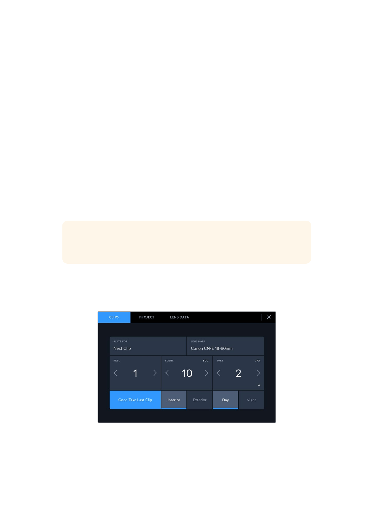
Entering Metadata
Metadata is information saved inside your clip, such as take numbers, camera settings and
other identifying details. This is extremely useful when sorting and processing footage in
postproduction. For example, take, shot and scene numbers are essential organizational
tools, while lens information can be used to automatically remove distortion or better match
VFXassets to plates.
Your Blackmagic Studio Camera automatically saves some metadata to each clip, such as
camera settings, timecode, date and time. You can use your camera’s slate to add many
additional details.
Slate
Swipe left or right on your camera’s touchscreen from the main view to bring up the slate.
The slate is divided into ‘clips’, ‘project’ and ‘lens data’ tabs. The ‘clips’ tab contains information
that may vary clip by clip, while ‘project’ is where you enter details common between clips,
such as the project name, director, and camera and operator ID. The ‘lens data’ tab displays
information about the lens fitted to your camera. If the lens automatically sends information
back to your camera it will be displayed here. You can also enter lens data manually.
TIP Metadata entered into the slate is viewable on your camera’s HDMI or SDI output
when ‘display status text for’ is set to ‘director’ on the ‘monitor’ tab. See the ‘monitor
settings’ section in this manualfor more information.
‘Clip’ metadata
In standby mode, when your studio camera is ready to record, clip metadata will be saved to the
next recorded clip. You can use the ‘good take last clip’ button to apply a ‘good take’ tag to the
most recently recorded clip.
85Entering Metadata

Slate for
This setting shows the clip which the metadata currently displayed in the ‘clip’ applies to.
In standby mode, this refers to the next clip that will be recorded.
Lens Type
If you are using a lens with in built electronics that communicate with your camera, you can see
the lens model information here. To change or add any information regarding the lens you are
using, press the ‘lens data’ option above.
For more information refer to the ‘lens data metadata’ section in this manual.
Reel
Displays the current reel.
Your Blackmagic Studio Camera automatically increments reel numbers, so there is usually no
need to enter this manually. When you are moving to a new project and want to start from reel
‘1’ again go into the project tab of the slate and tap ‘reset project data’.
Scene
The ‘scene’ indicator shows the current scene number, and can also show the current shot
number and type.
The number on this indicator always refers to the current scene. You can adjust it with the left
and right arrows on either side of the scene number, or tap the scene number to enter the
scene number editor.
Scene numbers range from 1 to 9999.
By adding a letter to the scene number in the scene number editor, you can also indicate the
current shot. For example 23A indicates scene twenty three, shot one. If you have a shot letter
added to your scene number, your camera suggests the next scene number and shot letter
whenever you enter the scene number editor. For example, ifyour current scene number is 7B,
the camera suggests ‘8’ and ‘7C’.
The scene number indicator can also show information about the current shot type in the top
right corner. You can select these in the scene number editor at the right hand side of the
shotkeyboard.
The shot types available are:
WS wide shot
MS medium shot
MCU medium close up
CU close up
BCU big close up
ECU extreme close up
86Entering Metadata
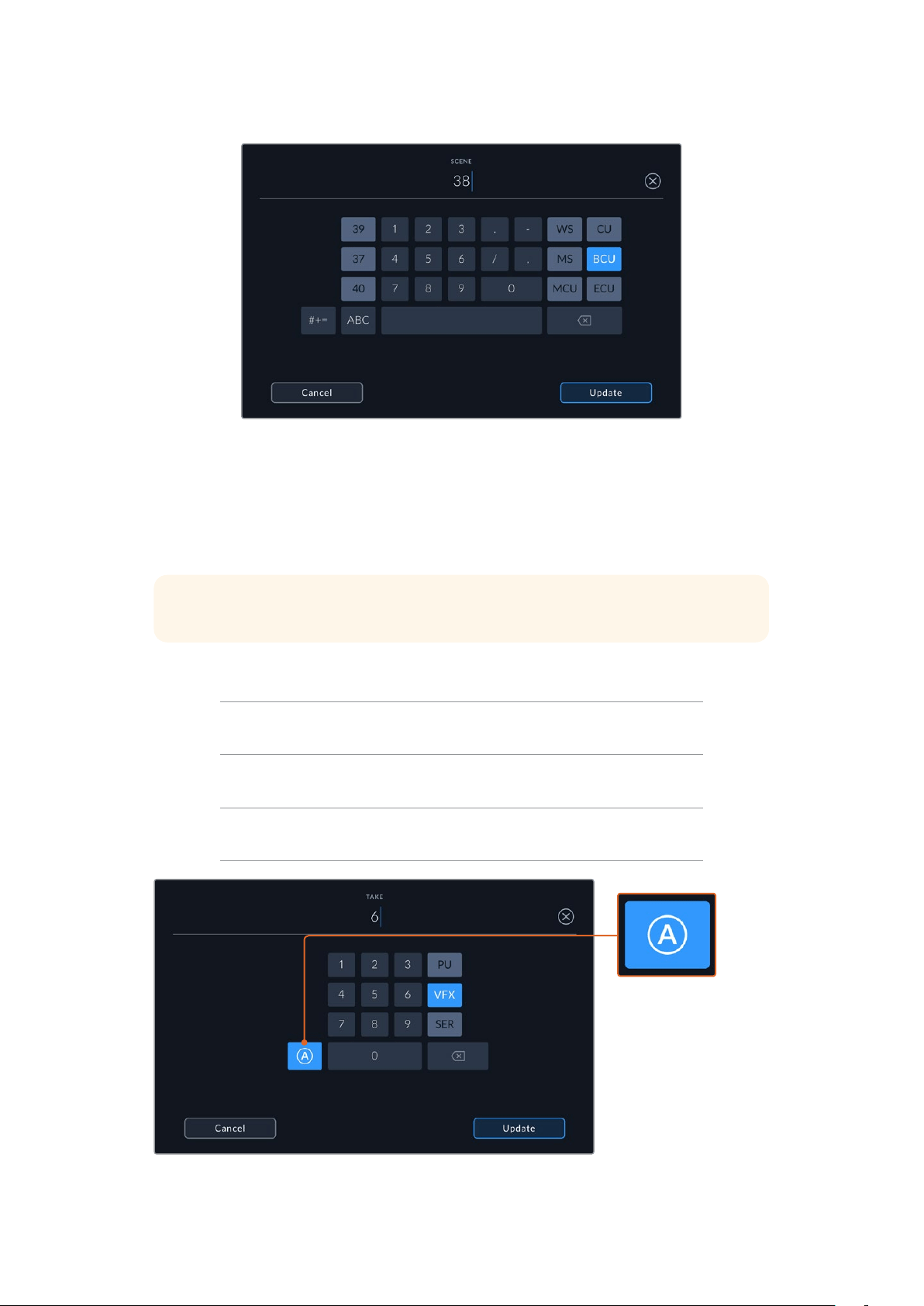
When entering ‘scene’ metadata, the camera prompts you with scene number
suggestions to the left of the touch keyboard, and shot types to the right
Take
The ‘take’ indicator shows the take number for the current shot. You can adjust it by tapping the
left or right arrows on either side of the take number, or tapping the indicator to enter the take
number editor.
TIP When the shot number or scene letter advance the take number reverts to ‘1.’
You can add descriptions in the take number editor. These are on the right of the take number
keyboard and correspond to the following scenarios:
P/U
‘Pick up.’ This refers to a reshoot of a previous take to add
additional material after principal photography has wrapped.
VFX ‘Visual effects.’ This refers to a take or shot for visualeffectuse.
SER
'Series.' This refers to a situation in which multiple takes are shot
while the camera is kept running.
Tap ‘A’ to automatically
increment the take
number for each clip
while in standby mode.
Asmall 'A' appears next
to the take number on
the slate when enabled.
When entering ‘take’ metadata, your Blackmagic Studio Camera will offer prompts
for additional shot types to the right of the touch keyboard
87Entering Metadata
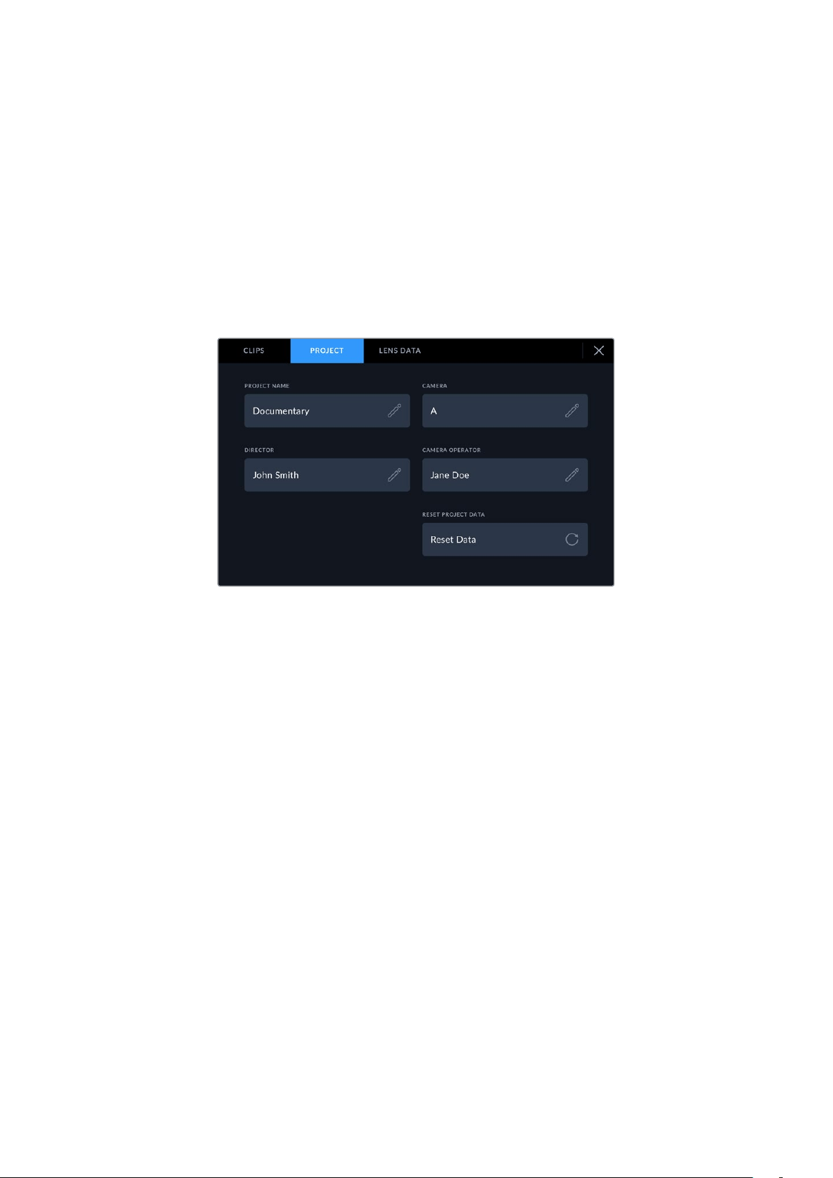
Good Take Last Clip
Tap the ‘good take last clip’ button to apply a ‘good take’ tag to the last recorded clip.
Adding a ‘good take’ tag makes it easy to identify good takes in post production.
Interior / Exterior
Tap ‘interior’ or ‘exterior’ to add a interior or exterior tag to the next clip.
Day / Night
Tap the ‘day’ or ‘night’ icons to add a day or night tag to the next clip.
‘Project’ metadata
‘Project’ metadata always refers to your project as a whole and is independent of clip numbers.
Enter project details using your camera’s ‘project’ slate tab
Project name
Displays your current project name. Tap the pencil icon to change the project name.
Camera
Displays a single letter camera index. Tap the pencil icon to change the camera index.
Director
Displays the director’s name for the current project. Tap the pencil icon to change
thedirectorname.
Camera Operator
Displays the camera operator. Tap the pencil icon to change the camera operator name.
Reset Project Data
To clear all the project information, tap the ‘reset data’ button.
88Entering Metadata
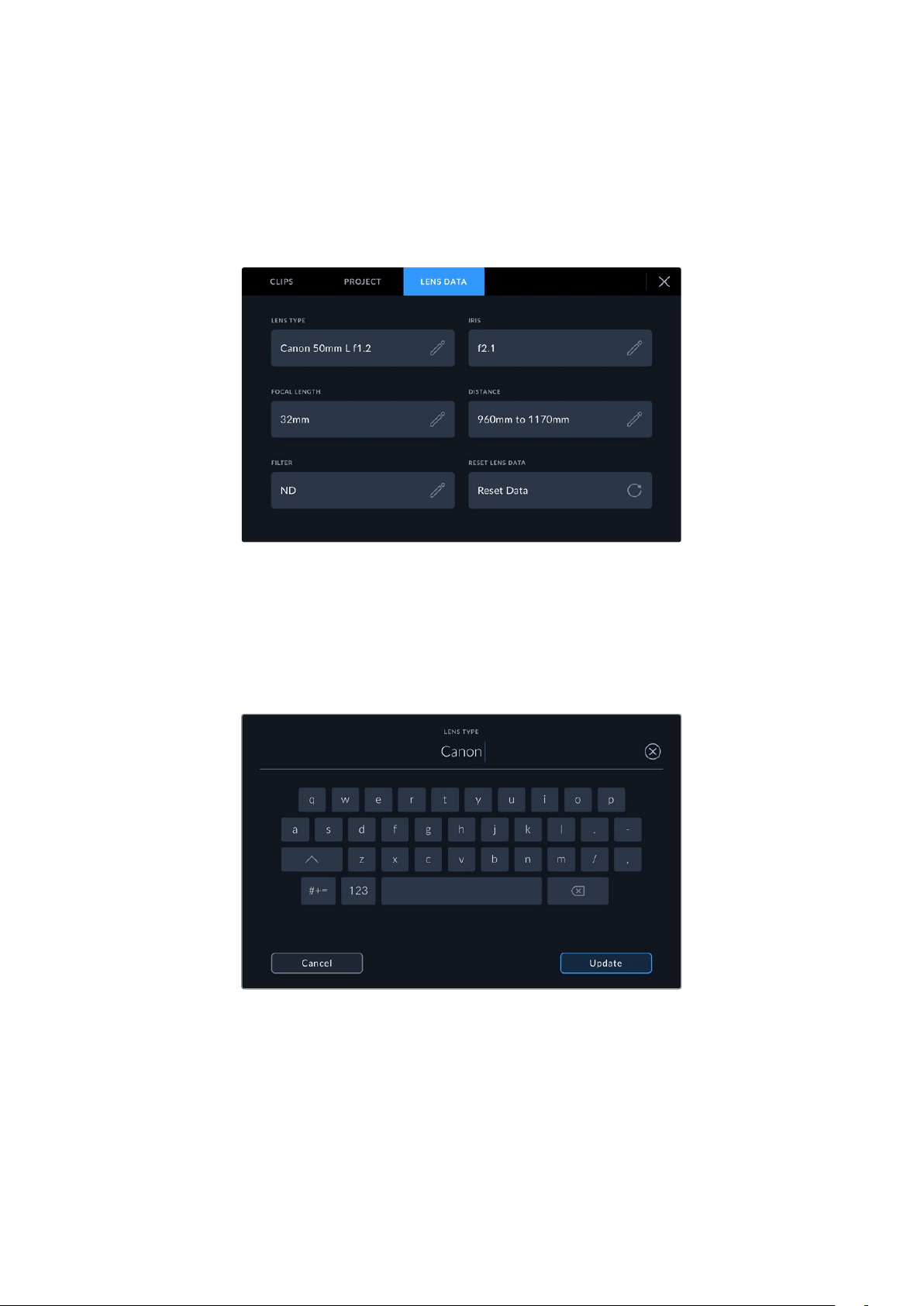
‘Lens Data’ metadata
These settings display information about the current lens fitted to your camera. Many electronic
lenses automatically supply information such as the lens model, aperture and focal length. Ifyou
are using a lens that does not provide this information, or you want to enter additional data, you
can tap the pencil icon in this setting to enter the information manually. This will bring up the
‘lens data’ menu, which contains the following information:
The ‘lens data’ menu showing information automatically populated from
an attached lens, and filter information that has been manually entered
Lens Type
Shows the lens model. If your lens type is not automatically shown here, you can tap this
setting to enter the data manually. Your camera has an internal database stored formany
commonly used lenses, so if you need to enter data manually, your camera will suggest
names automatically as you type. This makes entering data much faster.
Use the touch keyboard to enter lens data if it is not provided automatically
Iris
Shows the iris aperture setting at the start of your clip. This information can be displayed in
f- or T-stops depending on the lens used, if supplied automatically. Tap this setting to enter
data manually.
Focal length
Shows the focal length setting of the lens at the start of the recorded clip. When
automatically supplied, this is shown in millimeters. Tap this setting to enter the focal
length manually.
89Entering Metadata
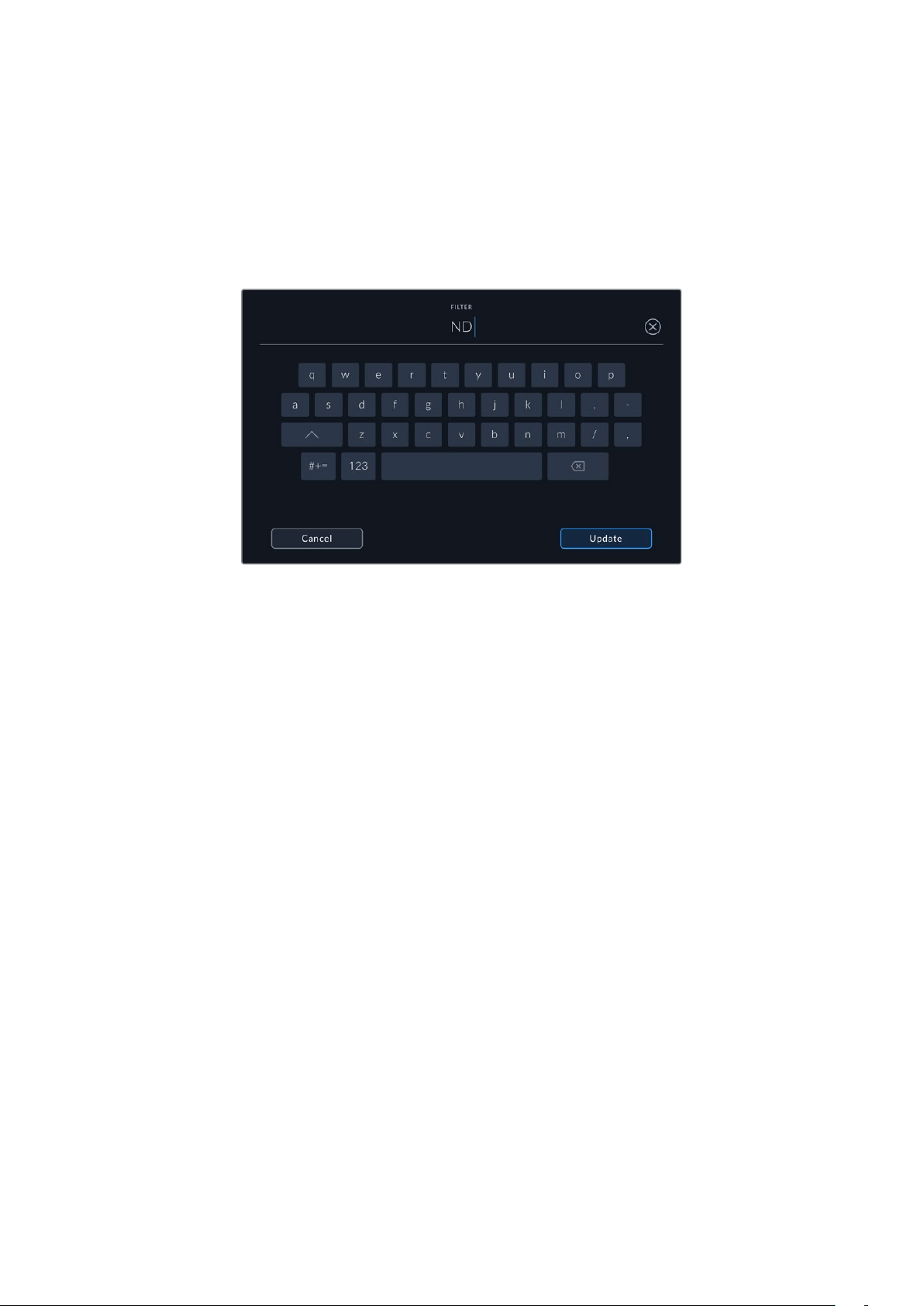
Distance
Shows the focus distance settings of the lens for the recorded clip. Some lenses can
provide this data automatically and it will be provided in millimeters. You can also enter this
data manually.
Filter
Shows the current lens filters used. Tap this setting to enter data manually. You can make
multiple entries separated by commas.
Filter information needs to be entered manually
You can clear lens data at any time by tapping the ‘reset lens data’ icon in the ‘lens data’ menu.
All lens data will be cleared and repopulated with any lens data automatically provided by the
currently fitted lens. If you have manually entered any information into these fields, you will
need to reset the lens data the next time you mount a lens, otherwise the manually entered
value will remain.
Streaming Video
Blackmagic Studio Camera 6K Pro and 4K Pro G2 have a built in streaming engine that enables
the camera to stream directly to platforms such as YouTube, Facebook Live and Twitch.
You can also connect your studio camera to an ATEM switcher on the same Ethernet
network, or via the Internet anywhere in the world using an optional ATEM Streaming Bridge.
When streaming to an ATEM switcher, this setup also includes tally, talkback and camera
control functionality.
Below are two examples showing Blackmagic Studio Camera 6K Pro connected to an ATEM
switcher using an ATEM Streaming Bridge. The first shows connecting locally over a network
and the second illustration shows transmitting video over the Internet using a smartphone.
90Streaming Video
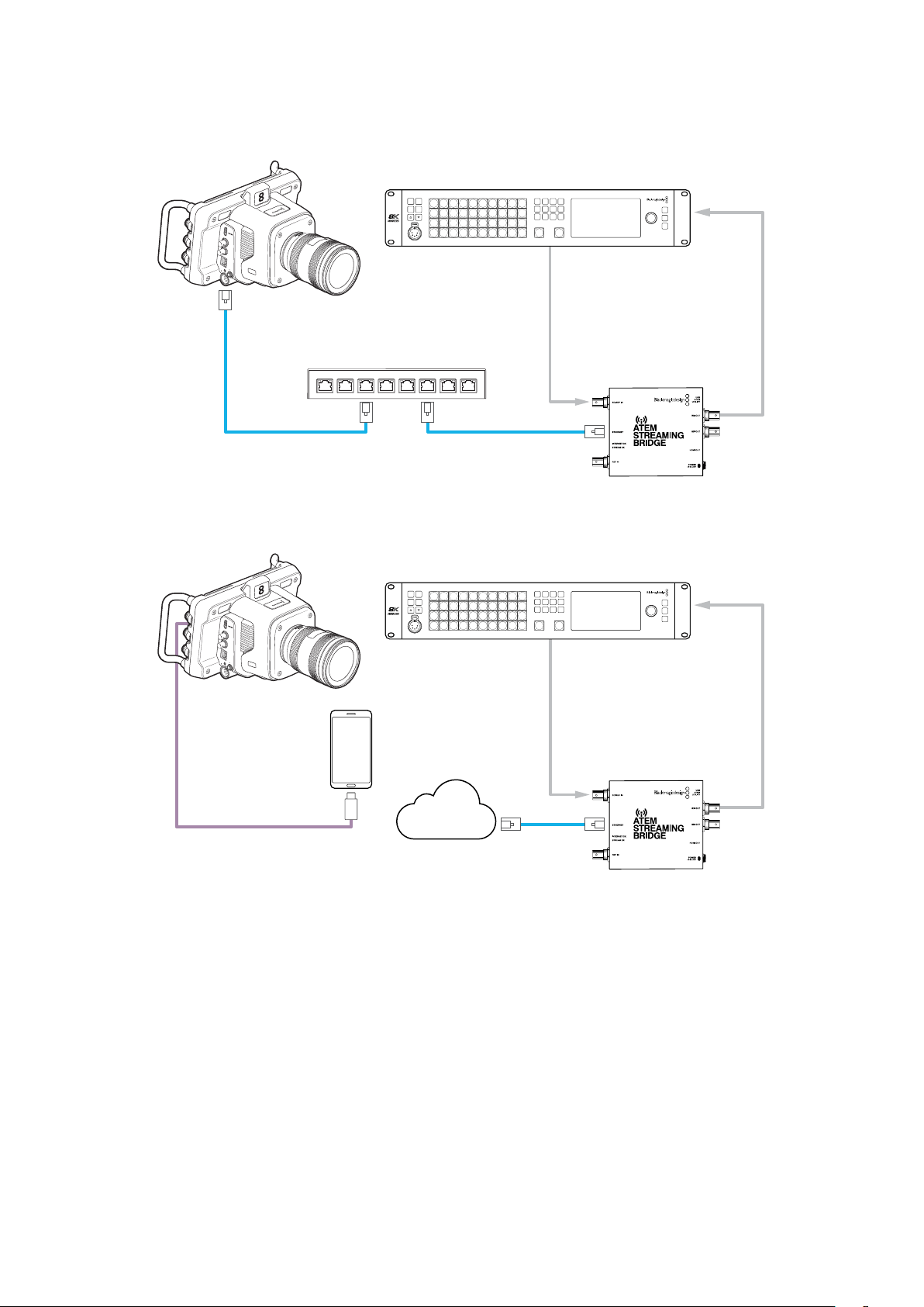
Connecting over a Network
SDI in
SDI out
SDI out
SDI Ref In
Ethernet
Network
Blackmagic
Studio Camera 6K Pro
ATEM
Constellation 8K
SDI IN
SDI OUT
ETHERNET
+12V
+12V
6
K
PROD
TALK
ENG
TALK
CALL
PGM
MIX
5
4
3
2
1
1 2 3 4 5 6 7 8 9 10
KEY 1
MIX
DSK 1
MIX
DSK 2
MIX
FTB
BARS BLACK MP1 MP2
MIX WIPE DIP DVE
LOCK
MENU
SET
11 12 13 14 15 16 17 18 19 20
21 22 23 24 25 26 27 28 29 30
31 32 33 34 35 36 37 38 39 40 CUT AUTO
ATEM Streaming Bridge
Connecting over the Internet
Blackmagic
Studio Camera 6K Pro
SDI IN
SDI OUT
ETHERNET
+12V
+12V
6
K
USB-C
SDI in
SDI out
SDI out
SDI Ref In
Ethernet
ATEM
Constellation 8K
PROD
TALK
ENG
TALK
CALL
PGM
MIX
5
4
3
2
1
1 2 3 4 5 6 7 8 9 10
KEY 1
MIX
DSK 1
MIX
DSK 2
MIX
FTB
BARS BLACK MP1 MP2
MIX WIPE DIP DVE
LOCK
MENU
SET
11 12 13 14 15 16 17 18 19 20
21 22 23 24 25 26 27 28 29 30
31 32 33 34 35 36 37 38 39 40 CUT AUTO
ATEM Streaming Bridge
Internet
91Streaming Video
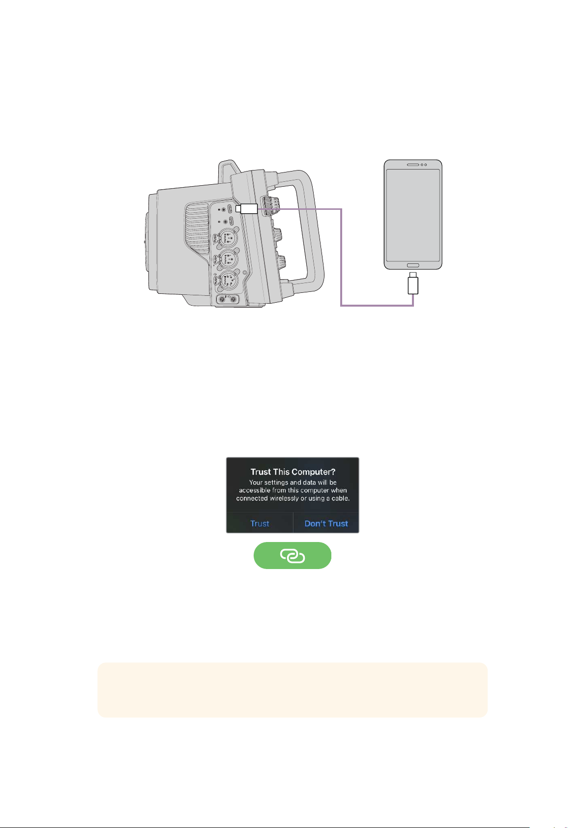
Smartphone Setup
Connect a smartphone to your camera’s USB-C expansion port using a USB-C cable. This
connection lets you set up fast and be streaming to the world in any location where your
smartphone has a 4G or 5G cellular connection.
USB-C
USB-C
AUDIO IN
USB
Settings
The first step to setting up your smartphone for internet streaming is to make sure it has hotspot
activated.
1 On your iOS device open settings>personal hotspot and make sure the ‘allow others to join’
option is on.
2 You will see a message appear asking whether to trust the connected computer. Select
‘trust’ and a green tethering icon will be visible on the screen. This is how you can verify the
connection is working.
The tethering icon will appear when enabled
Your smartphone’s clock will always appear within a green background icon while tethering
is enabled.
For Android devices, swipe the screen to display the quick menu. Press and hold the hotspot
icon and then turn on USB tethering.
TIP Once you have finished streaming, we recommend turning off tethering on your
phone to save your phone’s battery life.
92Smartphone Setup
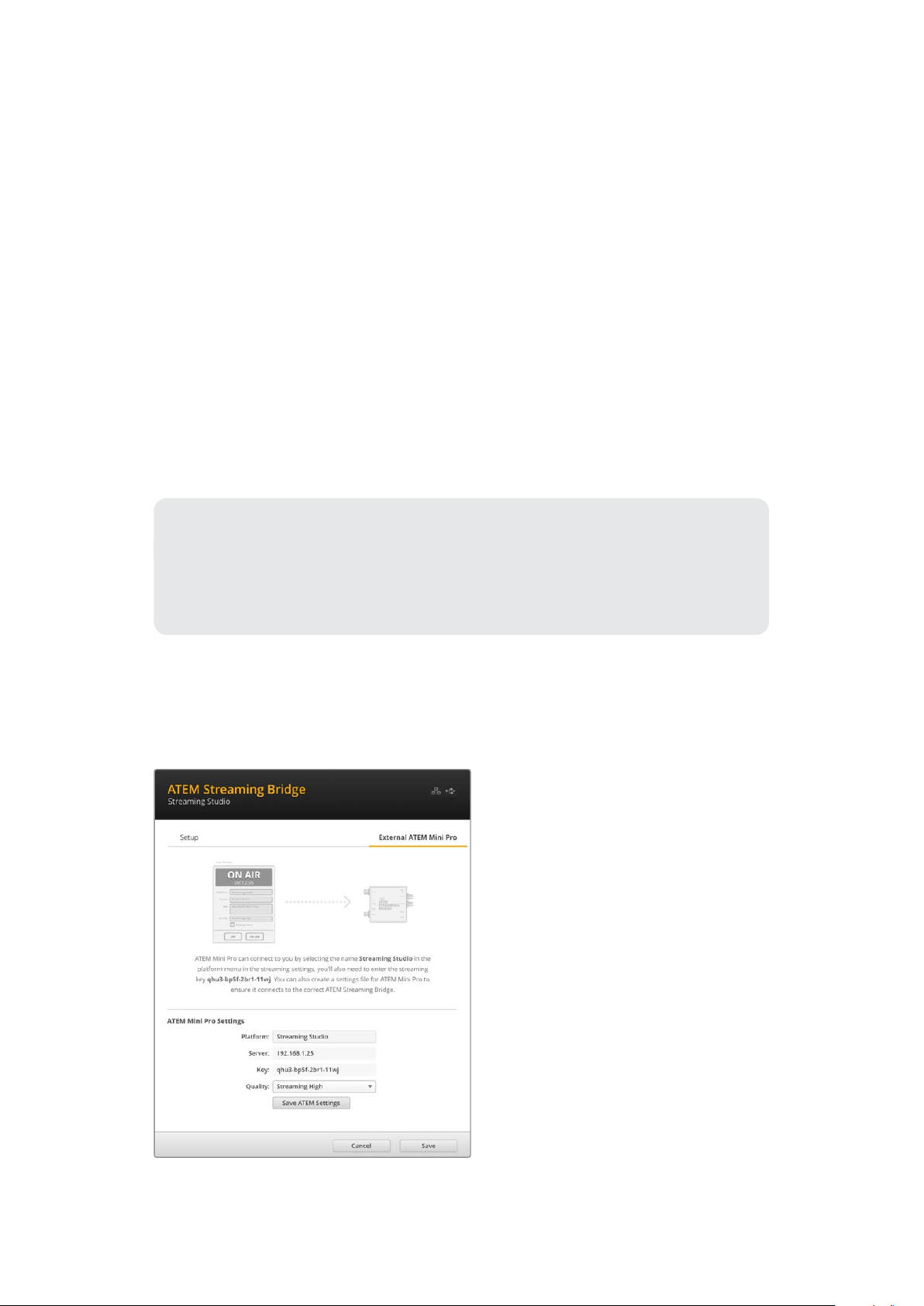
Setting the ATEM Camera ID
The ATEM camera ID is a setting in your camera’s menu settings that determines which SDI
input your Studio Camera 6K Pro is connected to on the ATEM switcher. When the camera ID
corresponds to the switcher’s input number, your camera will detect tally data for that input and
tally and camera control will work correctly.
For more information on setting your camera’s ATEM Camera ID, refer to the ‘setup settings’
section earlier in this manual.
Creating the XML File
To create an XML settings file connect ATEM Streaming Bridge to the internet by plugging a
network cable from the ‘Ethernet’ port to an internet router or network switch. Connect ATEM
Streaming Bridge to your computer using a USB-C cable and launch ATEM Setup.
In the setup tab, confirm the network settings are correct and select ‘Internet’ from the
‘streamservice’ options. You should see a ‘visible worldwide’ message in the internet status
box. This means everything is working correctly.
A Note About Port Forwarding
If you see a port forwarding or UPnP error in the ‘internet status’ box you will need to
ask your internet provider or network administrator to set up port forwarding on your
internet connection to ‘TCP port 1935’.
Exporting the XML File
Once you have confirmed your settings in the ATEM Setup tab and have successfully
connected your ATEM Streaming Bridge to your network or the internet, you can export the
XML setup file.
1 Click the ‘external ATEM Mini Pro’
tab in the top right of the window.
2 Click in the ‘platform’ box and
type a new name. This name will
be the name listed in the remote
Blackmagic Studio Camera’s
platform menu.
3 Select the quality you want to
stream. This setting will set the
quality setting in the remote
studio camera.
4 Click the ‘Save ATEM Settings’
button, choose a location on your
computer to save the XML file and
click ‘save’.
5 You can now email the saved XML
file to the remote operator.
93Smartphone Setup
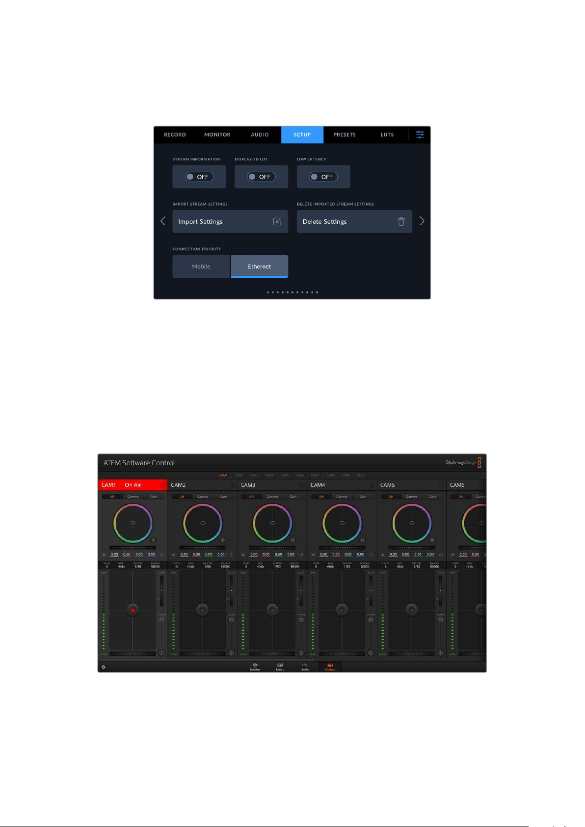
Loading the XML File
To import an XML settings file in to your studio camera, copy the file to a USB-C flash disk.
1 On the ninth page of your camera’s setup menu, tap on the button labeled ‘import settings’.
2 At the top of the screen, tap the flash disk where the xml settings file is saved. Tap the file
name and then tap ‘import’. After the setup file has been successfully imported, the ATEM
Streaming Bridge will automatically be selected in your camera’s platform menu.
All you need to do now is tap your camera’s live stream button to turn the stream ‘on’.
You can test your setup is working by getting the switcher operator at the studio to switch to
your camera. You will see the tally light illuminate on the camera including a red tally border
around the camera’s LCD. When your camera is switched to the preview output, the tally will
illuminate green.
Try adjusting the iris and pedestal in ATEM Software Control’s camera page to test camera control
94
Smartphone Setup
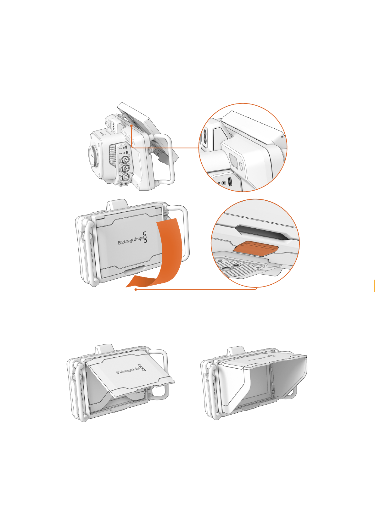
Using the Sun Hood
The sun hood helps you to see the screen in bright or sunny conditions. To attach the sun hood,
place its top edge along the top ridge of the Blackmagic Studio Cameras LCD and hinge it
down until it clicks into place.
Place the top edge of the sun hood into the slots above the LCD and lower the hood into
position. A latch underneath the LCD will secure the hood to the camera. When removing the
sun hood, press the latch to release the hood and then lift the hood away from the camera.
Once attached, open the top shade completely, allowing for the side flags to spring open then
let the top rest on the flags.
When the top shade is opened, the side flags will also open
95Using the Sun Hood
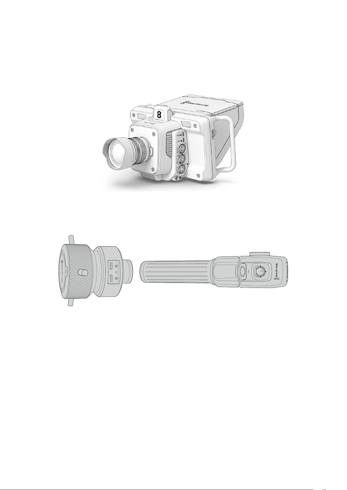
The sun hood provides additional protection for the 7” screen, and can be removed quickly and
easily. If you want to close the sun hood, fold down the side flags first, then lower the top shade
until it clicks into its frame.
To remove the hood, press the latch on the bottom of the frame to release it and then gently lift
away from the camera.
The sun hood helps protect the screen and provides shade in bright conditions
Blackmagic Zoom and Focus Demands
Blackmagic Zoom Demand and Blackmagic Focus Demand are optional accessories for
controlling focus and zoom when using compatible lenses with Blackmagic Studio Cameras.
Youcan read more about compatible lenses later in this section.
Each unit attaches to a tripod handle on your tripod or camera pedestal. This lets you control
focus and zoom while simultaneously panning and tilting the camera using both hands.
Additional buttons and controls let you refine the speed and sensitivity of the zoom control,
engage talkback, monitor program return and more.
USB
-
C
CAM LOOP
SPEED
96Blackmagic Zoom and Focus Demands
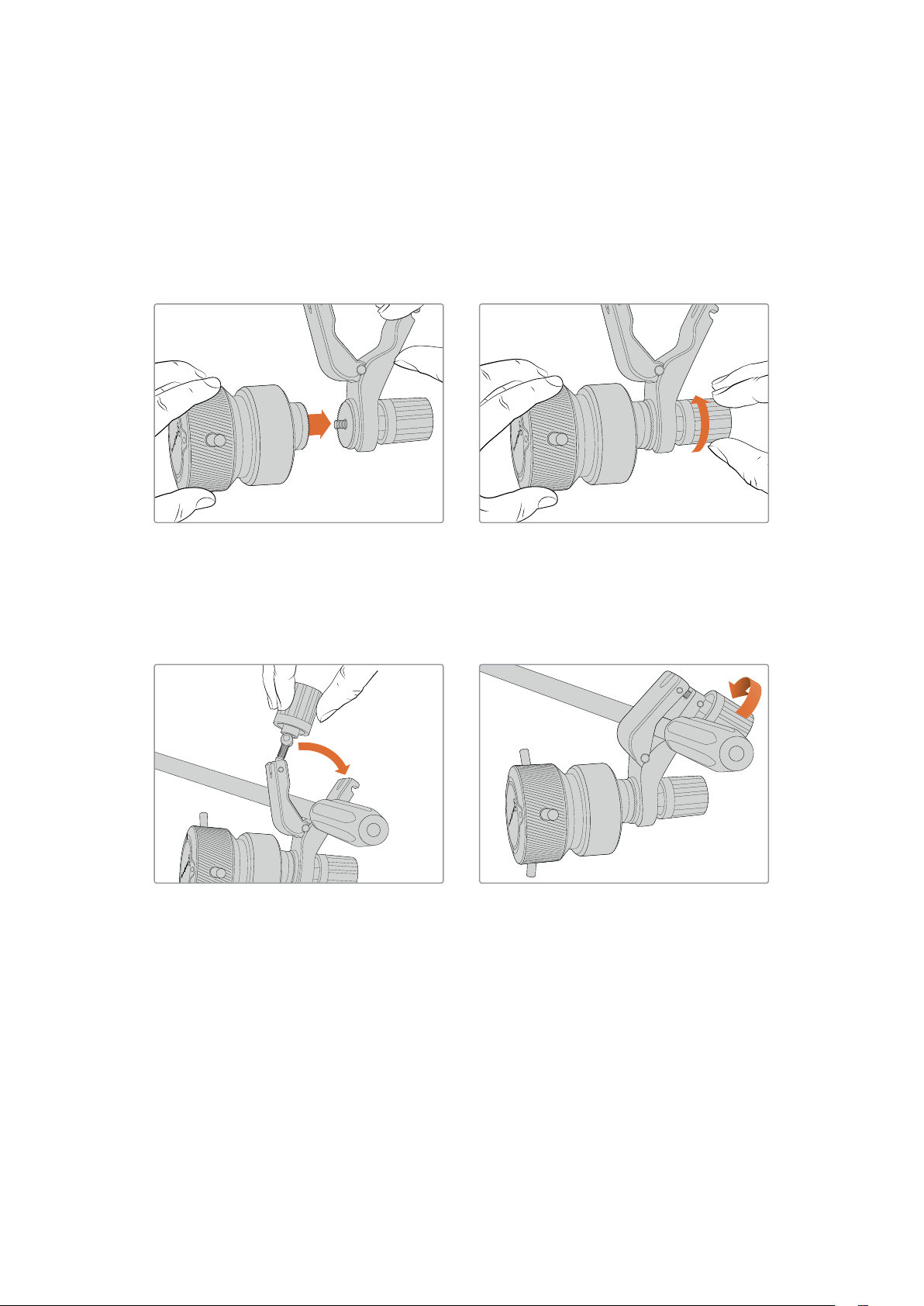
Connecting and Attaching to your Camera
Attaching to Tripod Handles
Each unit attaches to a tripod handle via their mounting brackets. Attach each unit to the
brackets via their rosette mounts.
To attach the demand units to their brackets, simply connect them together via their rosette
mounts and secure them by tightening the fastening knob.
1 Place the zoom demand or focus demand against their bracket’s rosette mount.
2 Tighten their fastening knob so the demand units are firmly attached to their brackets.
Now that the units are attached to the brackets, you can attach the brackets to the tripod arms.
One end of each bracket contains a ‘T’ shaped latch that hinges into a slot and is then tightened.
1 Loosen the latch by unscrewing the latch knob in a counterclockwise motion. This will
release the ’T’ shaped latch.
2 With the latch open, place the bracket onto the tripod arm and clamp the bracket shut by
closing the latch into its fastening slot. Rotate the bracket to your preferred position on the
tripod arm.
3 Tighten the latch knob to secure the bracket to the tripod arm.
97Blackmagic Zoom and Focus Demands
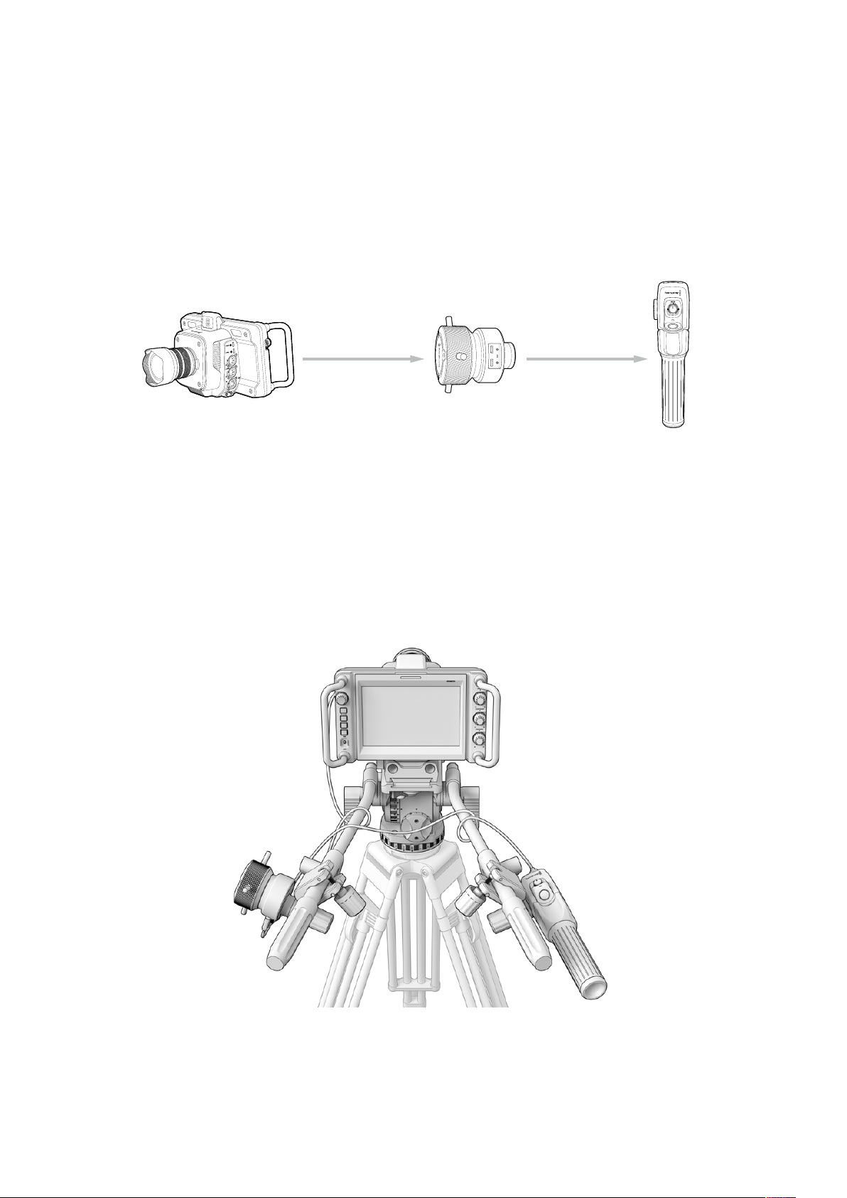
Connecting to Your Camera
Blackmagic Focus and Zoom Demands have two USB-C ports. This lets you use one unit
individually, or both units together.
Each unit is supplied with a 1 meter long USB-C cable which is connected directly from either of
your studio camera’s USB-C expansion ports to the demand unit’s ‘cam’ port.
If you are using both demand units, daisy chain them together by connecting the first unit to the
second unit via USB-C.
Blackmagic
Focus Demand
Blackmagic
Zoom Demand
Blackmagic
Studio Camera 4K Pro
USB-C
A or B
USB-C
CAM
USB-C
LOOP
USB-C
CAM
USB-CCAM LOOP
Daisy chaining allows for both units to be controlled using one USB port on your studio camera,
letting you use the second port for an external USB flash disk. For example, connect a USB-C
cable into either of the camera’s expansion ports A or B and connect the other end of the cable
into the focus demand’s ‘cam’ port. With a second cable, plug the focus demand’s ‘loop’ port
into the zoom demand’s ‘cam’ port.
The USB-C cable has locking screws on each end to secure the connectors to each unit,
preventing accidental disconnection. You don’t have to use the locking screws, but they are
helpful for studio setups where the units are always connected to your studio camera.
The Blackmagic Focus and Zoom Demands let you control focus and zoom
without looking away from the screen
98
Blackmagic Zoom and Focus Demands
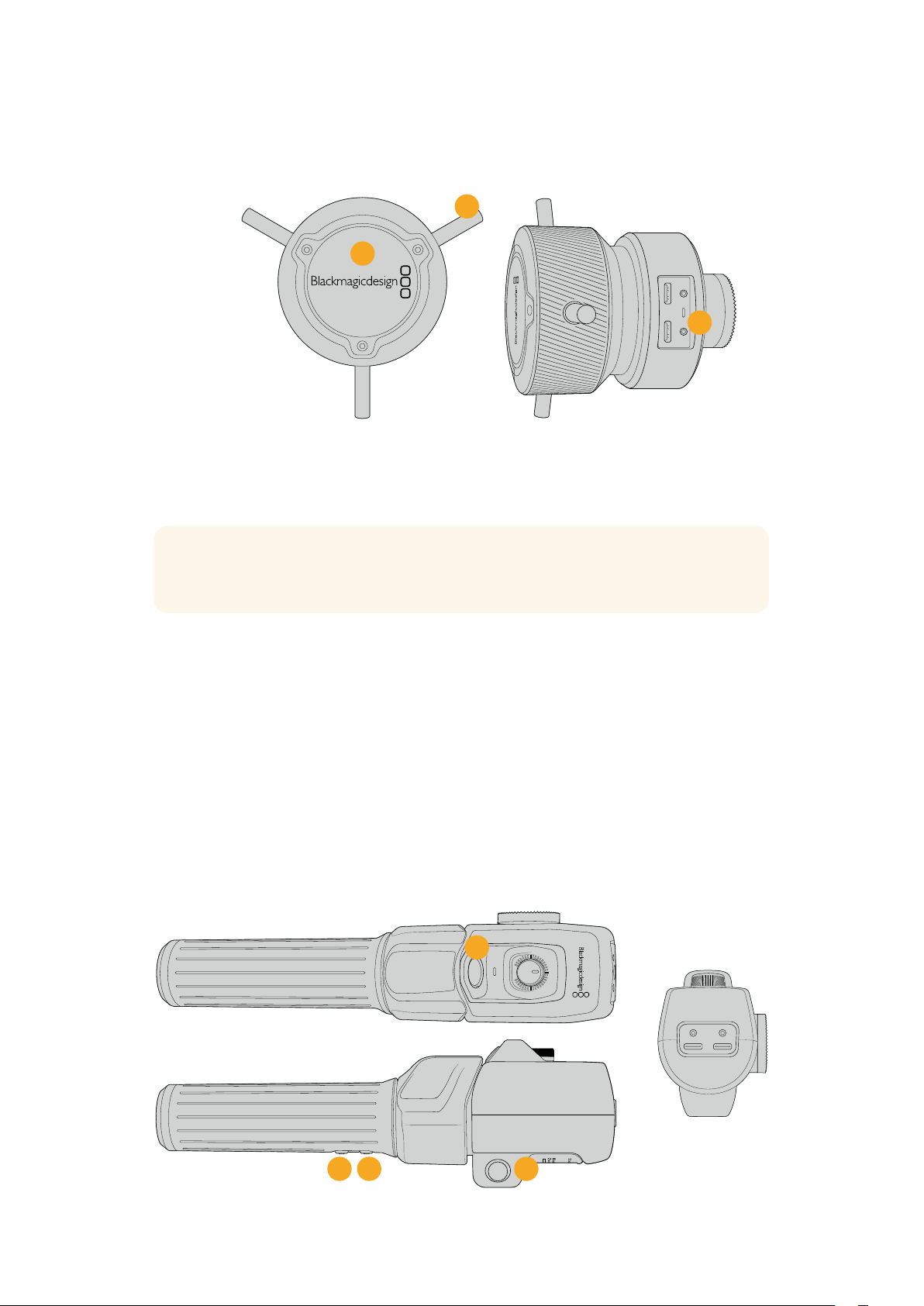
Using Blackmagic Focus Demand
This section describes the features and connectors on Blackmagic Focus Demand.
USB
-
C
CAM LOOP
3
2
1
1 Control Knob
Rotate the focus wheel clockwise to focus on subjects closer to the lens, or
counterclockwise to focus on subjects further away. You can change the focus direction in
the menu by setting it either ‘forward’ or ‘reverse’.
TIP If you are also using a Blackmagic Zoom Demand, press the quick zoom button to
magnify the image as you focus using the focus demand.
2 Control Pins
These three pins expand the diameter of the control surface to let you make finer focus
adjustments with the tip of a finger.
3 USB ports
Allows for connecting the focus demand to the camera and daisy chaining to the zoom
demand. The ‘cam’ port is also used for updating the internal software via the Blackmagic
Camera Setup utility.
Using Blackmagic Zoom Demand
The controls on the Zoom Demand are mappable through the Camera settings. To change the
button functions, refer to the ‘setup settings’ chapter in the ‘settings’ section.
The following commands are set as default:
CAM LOOP
USB
-
C
2
3
4
SPEED
1
99Blackmagic Zoom and Focus Demands
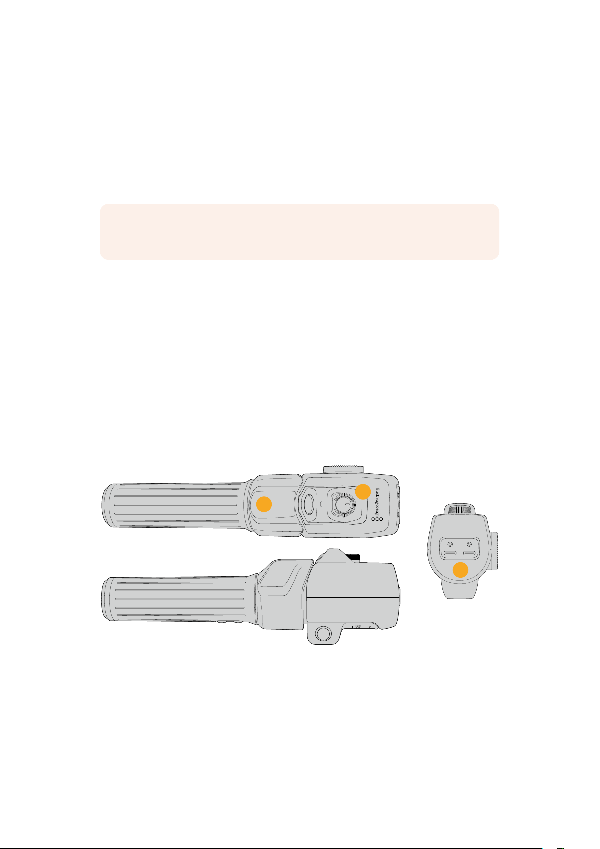
1 Zoom F1
This is the zoom function button 1. By default, it is mapped as a ‘record’ button for
recording to an external drive connected to an available USB-C port on your Blackmagic
Studio Camera.
2 Zoom F2
This is the zoom function button 2. On the other side of the controller is an identical button
that performs the same function, allowing for left and right handed control. By default, it is
set as a quick zoom function which instantaneously punches into the live image.
NOTE The quick zoom feature is only visible on the Blackmagic Studio Camera’s LCD
and will not be visible on the output video connected to aswitcher or recorder.
3 Zoom F3
This is the zoom function button 3. On Blackmagic Studio Camera 4K Pro and 6K Pro
models, the default action for this button is set to program return. This would normally be
a switcher’s program return feed, but can be any SDI signal connected to your camera’s
SDI input.
On Blackmagic Studio Camera 4K Plus, the default action is set to auto white balance.
4 Zoom F4
This is the zoom function button 4. On Blackmagic Studio Camera 4K Pro and 6K
Pro models, the default action for this button is set to push to talk. When connected
to an ATEMswitcher via SDI, press andhold the button to communicate with the
switcher operator.
On Blackmagic Studio Camera 4K Plus, the default action for this button is set to
frame guides.
CAM LOOP
USB
-
C
7
SPEED
5
6
5 Thumb Rocker
The zoom demand handle provides a thumb rocker control. Push the thumb rocker left
to zoom out, and right to zoom in. The direction of the zoom can be reversed using the
camera’s menu settings.
6 Speed Dial
Finely adjust the speed of the zoom by adjusting the speed dial at the top of the unit.
You can map this dial to also control the headphone level, iris adjustment and even focus
adjustment!
100Blackmagic Zoom and Focus Demands

7 USB-C Ports
Allows for connecting the zoom demand to the camera and daisy chaining to the focus
demand. The ‘cam’ port is also used for updating the internal software via the Blackmagic
Camera Setup utility.
Compatible Compact Servo Zoom EF Mount Lenses
On Studio Camera 6K Pro you can electronically control focus, iris and zoom on ‘compact-servo’
zoom lenses. Information such as lens name, iris, focus and zoom position values are all able to
be read and recorded by Studio Camera 6K Pro’s lens metadata system.
If you are operating in a live broadcast or studio environment, use of these lenses with
Blackmagic Zoom and Focus Demands is possible provided the iris switch on the barrel of the
lens is set to ‘A’, the focus switch is set to ‘AF’, and the zoom servo switch is set to ‘servo’.
Hybrid Compact Servo Zoom EF Mount Lenses
Canon CN-E 18-80mm T4.4 Compact-servo
Canon CN-E 70-200mm T4.4 Compact-servo
Compatible Micro Four Thirds Lenses
While more than 50 micro four thirds lenses will work with Blackmagic Focus Demand, the
following lenses will work with both focus and zoom demands on Blackmagic Studio Camera
4KPlus and 4K Pro models.
Power Zoom Lenses
Olympus 12-50mm f/3.5-6.3 ED M.Zuiko EZ Micro 4/3 Lens
Panasonic Lumix G X Vario PZ 45-175mm f/4.0-5.6 Zoom OIS Lens
Pancake power zoom lenses
Olympus 14-42mm M.Zuiko f/3.5-5.6 Digital ED EZ Lens
Panasonic Lumix G X Vario PZ 14-42mm f/3.5-5.6 Power O.I.S. Lens
101Blackmagic Zoom and Focus Demands
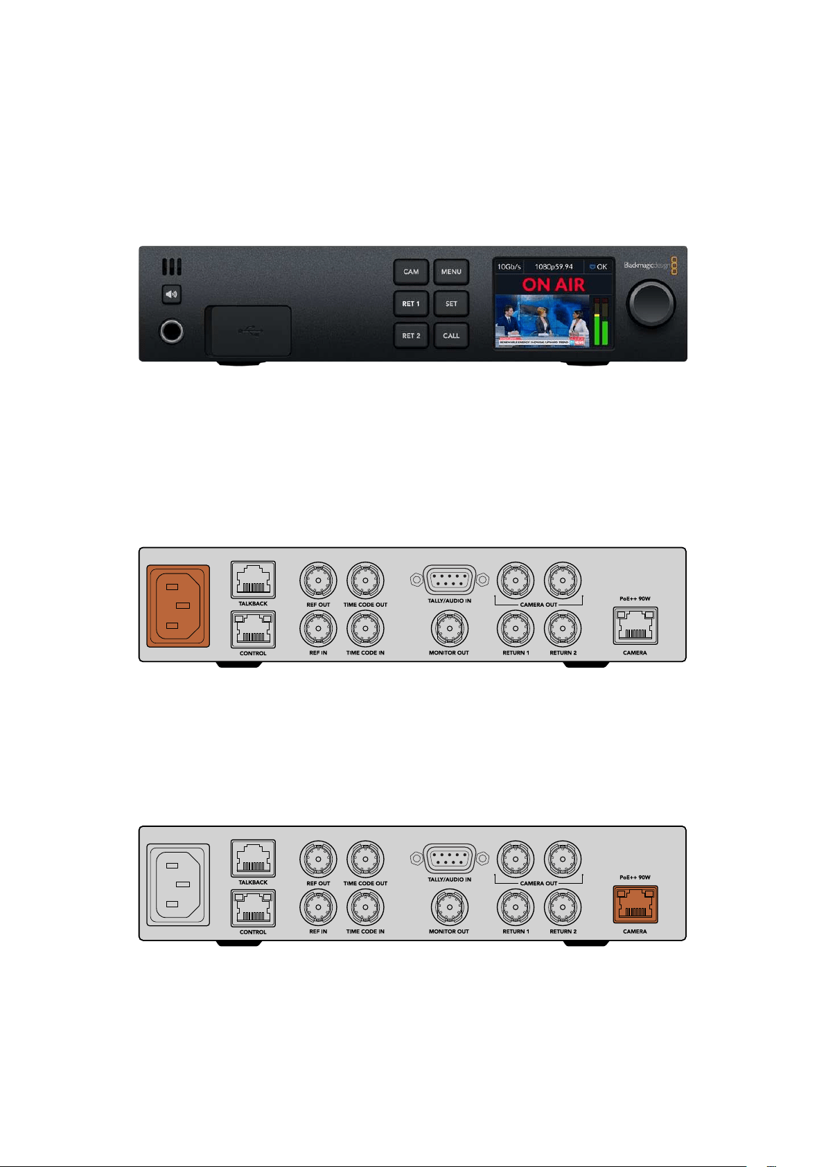
Blackmagic Studio Converter
Blackmagic Studio Converter provides a fast, simplified SMPTE fiber style setup with
Blackmagic Studio Cameras that have a 10G Ethernet connector. This means you can use
one single Ethernet cable to power the studio camera and supply all video and audio feeds,
including talkback, tally and camera control.
Getting Started with Blackmagic Studio Converter
To get started, all you need to do is connect Blackmagic Studio Converter to power, connect to
your studio camera via Ethernet and then connect to an ATEM switcher.
Plugging in Power
Plug a standard IEC power cable into the power connector on your Blackmagic Studio
Converter’s rear panel.
Connect power to your Blackmagic Studio Converter via a standard IEC power cable
Connecting your Camera
Connect one end of a standard CAT 6 network cable to the ‘camera’ Ethernet port on the rear
panel of your Blackmagic Studio Converter and the other end to the Blackmagic Studio Camera.
In general, a CAT 6 cable will work fine, however, for longer cable runs we recommend a well
shielded CAT 6A S/FTP cable.
The Ethernet connector locks securely to each unit ensuring that the
cable is not accidentally disconnected during broadcast.
102Blackmagic Studio Converter
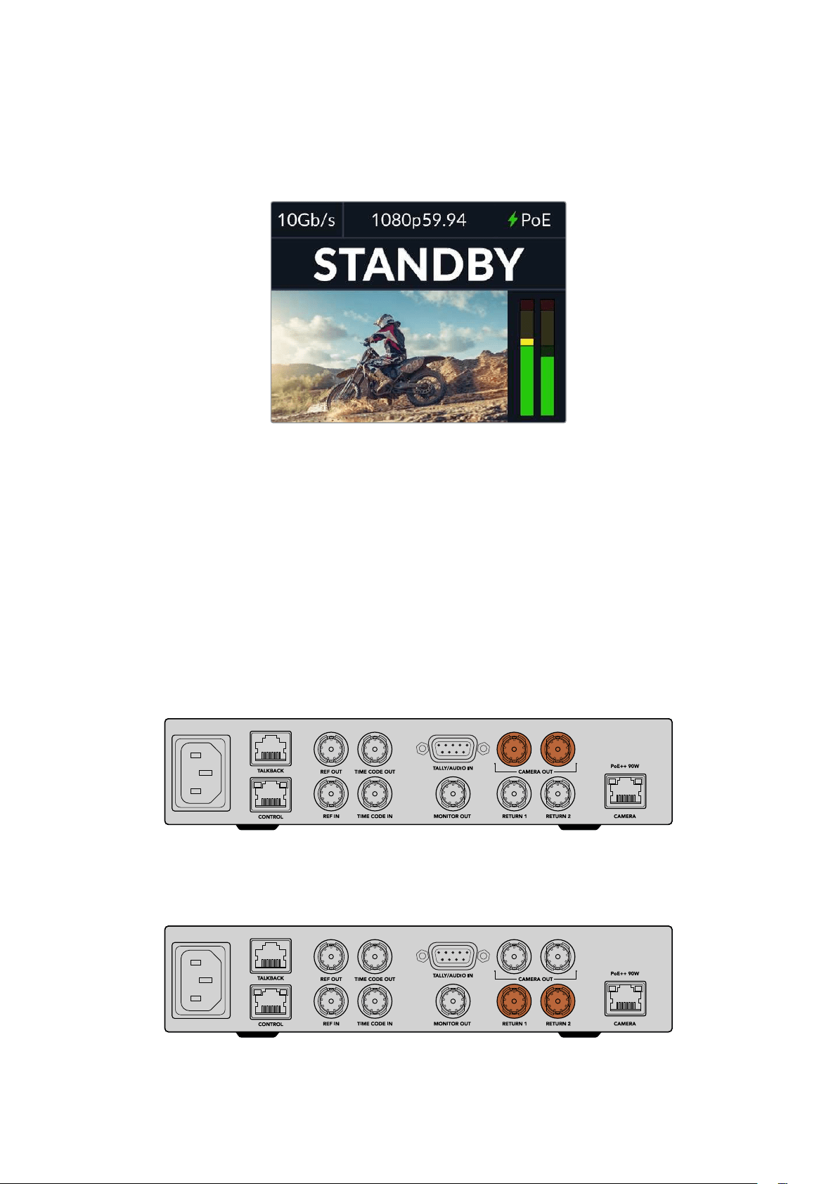
With the Blackmagic Studio Camera power switch set to the ‘on’ position, Blackmagic Studio
Converter will detect the camera and power the unit instantly. Establishing video will take
approximately 20-30 seconds. When video is confirmed, the image will appear with a ‘standby’
indicator to let you know the studio camera is standing by and ready to go to air.
When power and video is connected, the PoE
indicator will illuminate green, followed soon after
by the video image and ‘standby’ indicator
The studio camera image will now appear on your Blackmagic Studio Converter’s LCD. You can
see the video format your camera is set to and the audio meters will display the strength of the
audio signal.
Connecting to an ATEM Switcher
The next step is to connect your Blackmagic Studio Converter to an ATEM switcher.
1 Connect a BNC cable from one of your Blackmagic Studio Converter’s ‘camera out’
SDIconnectors to one of the ATEM switcher’s SDI inputs.
Both camera outputs are exactly the same so it doesn’t matter which one youuse. Twoare
provided in case you want to send the camera signal to other video equipment, for example
ISO recording on a HyperDeck.
Plug one of Blackmagic Studio Converter’s camera SDI outputs into any of the ATEM switcher’s SDI inputs
2 Connect a BNC cable from your ATEM switcher’s program return output to the ‘return 1’
BNC input on the studio converter’s rear panel.
Plug return sources into the ‘return’ inputs
103
Blackmagic Studio Converter
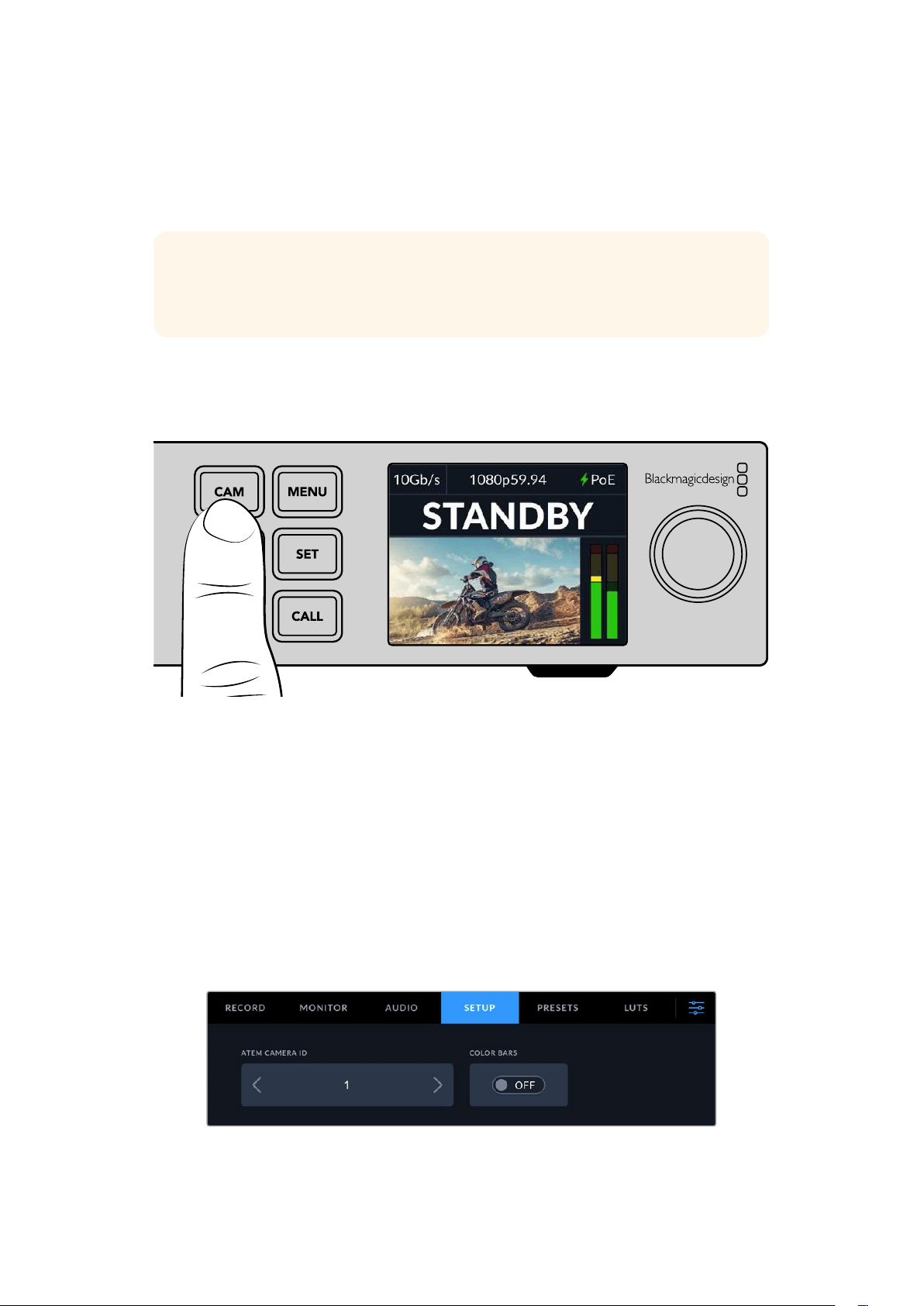
3 If you require any other return feeds to be sent to your camera such as a teleprompter feed,
an ISO feed from another camera, graphics or any other signal then plug this feed into
‘return 2’.
You don’t need to plug in audio cables as audio is embedded in the SDI video signal.
TIP SDI based ATEM switchers have many SDI outputs, however, if you need more
you can run the program return feed from the switcher through an optional Teranex
Mini SDI Distribution 12G or a Smart Videohub.
Checking the Return Feeds
Press the return 1 and return 2 buttons to monitor the return feeds. Press the ‘cam’ button to
monitor the camera image.
Press the camera, return 1 and return 2 buttons to check the camera signal and return feeds
Confirming Program Return on Blackmagic Studio Camera
Press and hold the program button on the Blackmagic Studio Camera. You should now see the
video that is connected to Blackmagic Studio Converter’s return 1 input displayed on the studio
camera’s viewfinder. Release the program button to return to the live camera image.
Setting the ATEM Camera ID on Blackmagic Studio Camera
The ATEM camera ID is a setting in your camera’s menu settings that determines which SDI input
your studio camera is connected to on the ATEM switcher. When the camera ID corresponds to
the switcher’s input number, your camera will detect tally data for that input and the tally light
will work correctly on your camera.
For more information on changing the ATEM camera ID, refer to the ‘menu settings’ section.
Change the ATEM camera ID using your studio camera’s ‘setup’ settings
104
Blackmagic Studio Converter
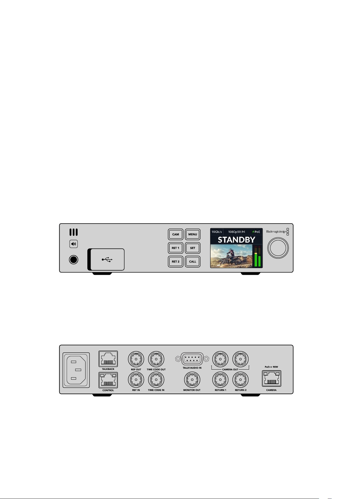
Checking the Return 2 Feed
Blackmagic Studio Camera will output the return 2 source via its HDMI connector. For example,
you could connect a teleprompter feed, a scorecard, or a pre-keyed video feed that is being fed
up from the Blackmagic Studio Converter. This can be used for presenters, or crew to view on
set on a large screen TV.
Checking Talkback
When using an ATEM switcher with built in talkback, the talkback audio is embedded in
channels 15 and 16 of the SDIsignal and carried over the Ethernet cable to your camera.
With headsets connected to the camera and the ATEM switcher, check that the camera
operator can communicate with the switcher operator.
That’s all there is to getting started and you are now ready to start your live production!
The next section of the manual will describe the additional connectors and how to use the
front panel.
Connectors
This section contains information on each of Blackmagic Studio Converter’s front and rear
panelconnectors.
Front Panel
Headphones
Plug a set of headphones into the audio jack to monitor audio via headphones.
USB
Plug your Blackmagic Studio Converter into a computer via the USB port to update the internal
software. Pull back the rubber dust cap to access the USB port.
Rear Panel
Talkback
If you need to plug in a third party analog talkback system, you can connect via the ‘talkback’
RJ-45 connector on the rear panel. Use the menu settings to change the talkback source
setting between embedded SDI and analog talkback.
105Blackmagic Studio Converter
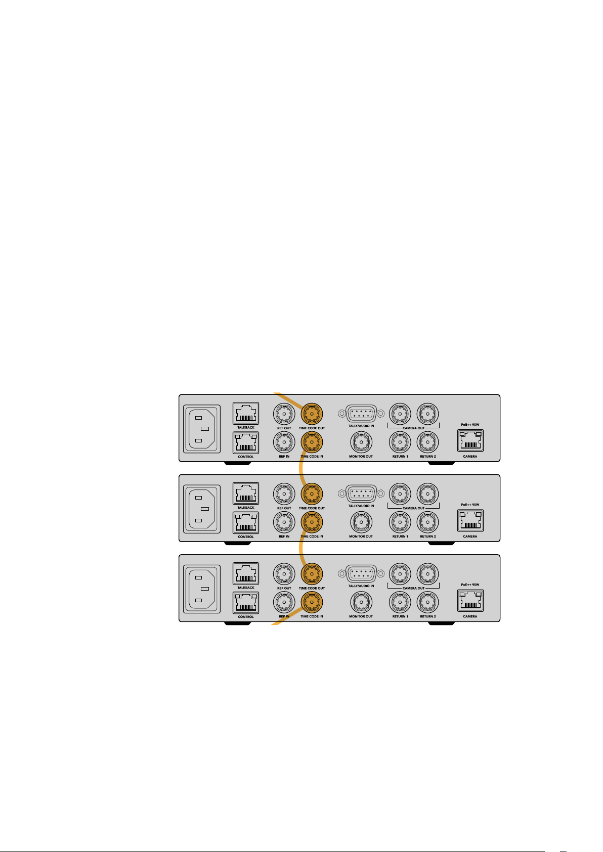
Control
This connector is not enabled in this software release.
Reference and Timecode
The reference and timecode connectors let you plug in timecode and reference from external
sources, or send external timecode and reference to other video equipment.
Traditional broadcast equipment often uses analog timecode and reference signals for syncing
all the devices. While Blackmagic Studio Cameras and Blackmagic Studio Converter use
reference and timecode embedded in the signal coming from the ATEM switcher, you can also
use a more traditional analog signal for referencing your camera or for inserting timecode.
This also means that if you are not connecting to a switcher at all and are operating in a
multicam environment where you may not have a switcher connected to the return 1 SDI input,
you can still sync all your cameras using an analog reference source. To output timecode when
you are not connected to a switcher, an SDI video signal needs to be connected to the return
1input to replace what would normally be the switcher’s return feed. A simple solution is to loop
the studio converter’s 2nd camera SDI output to the return 1 SDI input.
Looping Timecode and Reference
The reference out and timecode out connectors provide an analog loop through so if you
have multiple Blackmagic Studio Converters in a rack together you can just run a single analog
reference or timecode signal into the first unit and then loop through to each subsequent
converter to make sure they are all synced to the same analog reference or timecode source.
Studio Converter 3
Studio Converter 2
Studio Converter 1
106Blackmagic Studio Converter
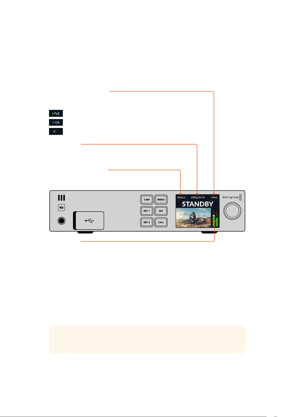
Using the Front Panel
When using Blackmagic Studio Converter, any information you need to know is displayed
on the unit itself via the built in LCD. Information displayed includes the image for the studio
camera, return 1 or return 2, audio meters, Ethernet connection status, current power source,
video format and timecode, plus on air status and camera name.
Camera Connection Status
Indicates whether the camera is powered via Ethernet or locally, plus the
status of the Ethernet connection.
- Connection established with power and video.
- Camera powered locally with video connection established.
- Camera not powered and video not connected via Ethernet.
Video Format
Indicates the video format currently being viewed
on the LCD.
Ethernet Connection Type
The Ethernet connection type shows you the speed of the
link that you are connected at, for example 10Gb/s or 1Gb/s.
Audio Meters
Displays the audio levels of the selected source.
Camera and Return Buttons
When you select a source, its image is displayed on the LCD and the levels for embedded
audio will be shown on the audio meters.
Speaker Button
Check the camera audio or any audio embedded in each return feed using the built in speaker
or by plugging in headphones. To listen, press and hold the speaker button and rotate the
settings dial to adjust the volume. A volume indicator will appear on the LCD home screen.
Release the button to mute the speaker.
Double press the speaker button to keep the speaker enabled. Press again to disable.
TIP If you are using multiple studio converters in a multi camera setup, the speaker
button is a helpful way to quickly confirm the audio from each camera.
Call Button
Holding down the ‘call’ button will flash the tally light on the studio camera. This lets you seek
the camera operators’ attention, or to let your operators know you are about to go live.
107Using the Front Panel
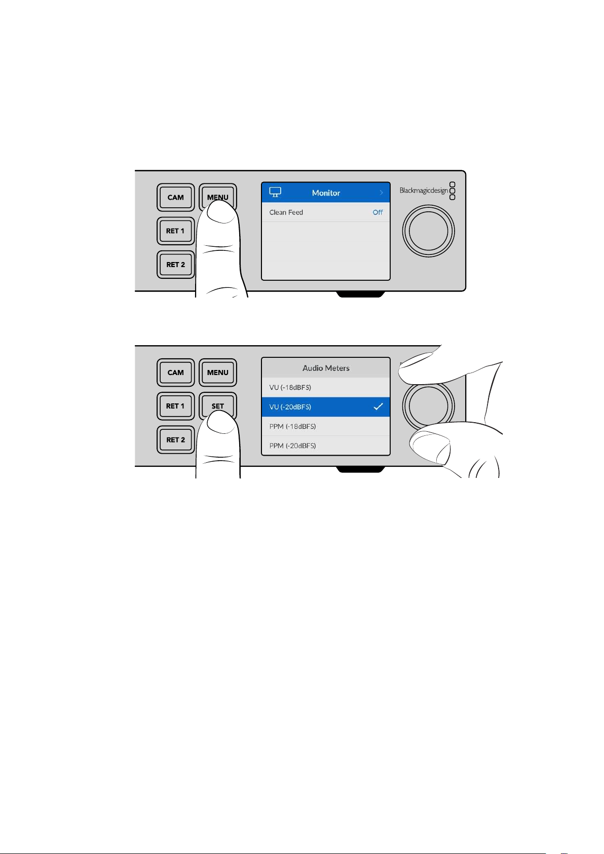
Menu Settings
All the settings for your Blackmagic Studio Converter are available in the LCD menu. To change
a setting:
1 Press the ‘menu’ button to open the settings menu.
2 Rotate the settings dial to select the desired menu page and press the ‘set’ button
to confirm.
3 Rotate the settings dial to select the settings you want to change and press ‘set’ to confirm
the change.
Your new settings are now applied. Press the ‘menu’ button to step back through the menu
andreturn to the home screen.
The next section of the manual describes each setting.
Monitor
Clean Feed - On/Off
Setting clean feed to ‘on’ will remove the status text from the monitor output so only the source
image is visible, for example the camera image or return feeds. For more information on the
monitor output, refer to the ‘using the monitor output’ section later in this manual.
108Menu Settings
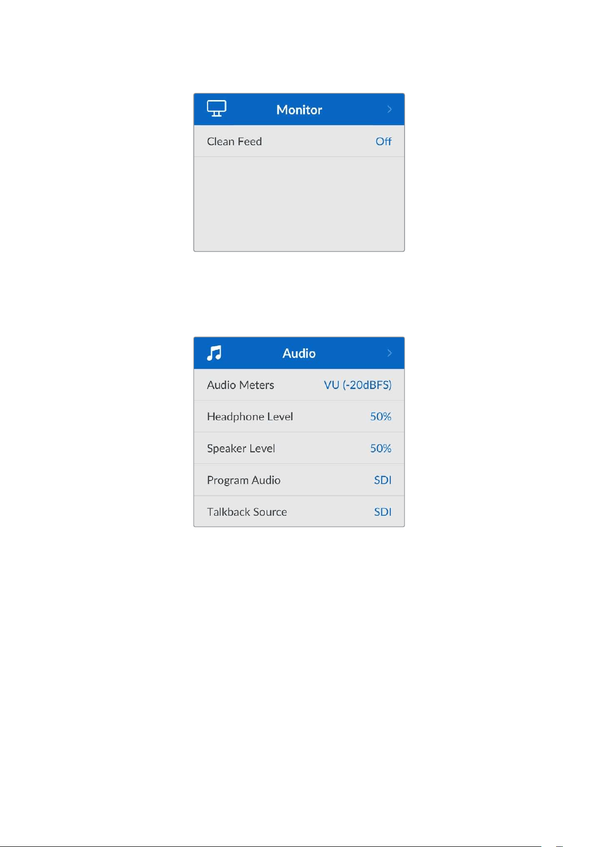
Audio
Audio Meters
To change the meter type, open the audio meters setting and select your preferred audio meter
display from the options. You can select between PPM and VU meters.
Headphone and Speaker Level
In addition to holding the speaker button down on the front panel and rotating the settings
knob, you can also adjust the speaker and headphones volume via the headphone and speaker
level setting. The default level is 50%.
Program Audio
Set the program audio to SDI or analog.
SDI - Uses the program audio from the SDI return feed plugged into the return 1 BNC connector.
Analog - Uses analog audio connected to the DE-9 serial connector. For example, you could
take an analog feed off a sound desk or a version of the audio with a different language
commentary mixed on top of the program audio.
Talkback Source
Set the talkback source to SDI or analog.
109Menu Settings
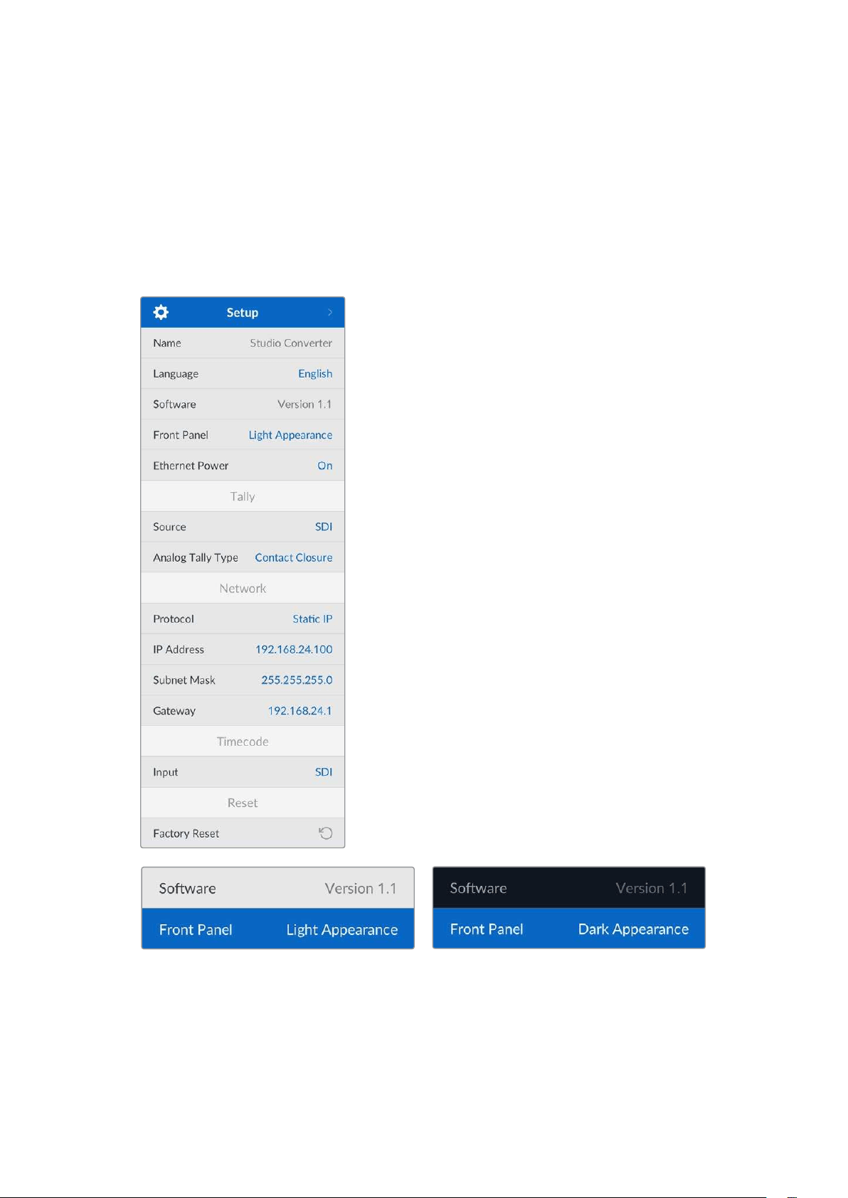
SDI - Uses the talkback embedded in the SDI program return feed plugged into the return
1 BNC connector. Select this setting when connected to an ATEM switcher with talkback
embedded in the video feed.
Analog - Uses analog talkback audio connected to the ‘talkback’ RJ-45 connector. The analog
setting is what you will want to use if you are integrating a third party talkback system, for
example ClearCom, RTS or Reidel.
Setup
Name
Displays the name of your Blackmagic Studio Converter.
Language
Blackmagic Studio Converter supports multiple
languages, including English, Chinese, Japanese, Korean,
Spanish, German, French, Russian, Italian, Portuguese,
Turkish, Ukrainian and Polish.
To select the language, open the setup menu and scroll
down using the settings knob. Press ‘set’ to confirm. Once
selected you will automatically return to the setup menu.
Software
Displays the current software version for your Blackmagic
Studio Converter.
Front Panel
Set your Blackmagic Studio Converter’s front panel to
‘light’ mode for a brightly illuminated LCD. Use ‘dark’
mode for dimly lit environments where a bright LCD may
be distracting, for example multiple studio converter units
mounted in a rack in a production facility.
Ethernet Power
Allows you to switch Ethernet power to your studio camera on or off.
As the quality of Ethernet cables can vary over long cable runs, setting Ethernet power to ‘off’
and powering your camera locally can increase performance over longer distances. Thedefault
setting is ‘on’.
110Menu Settings
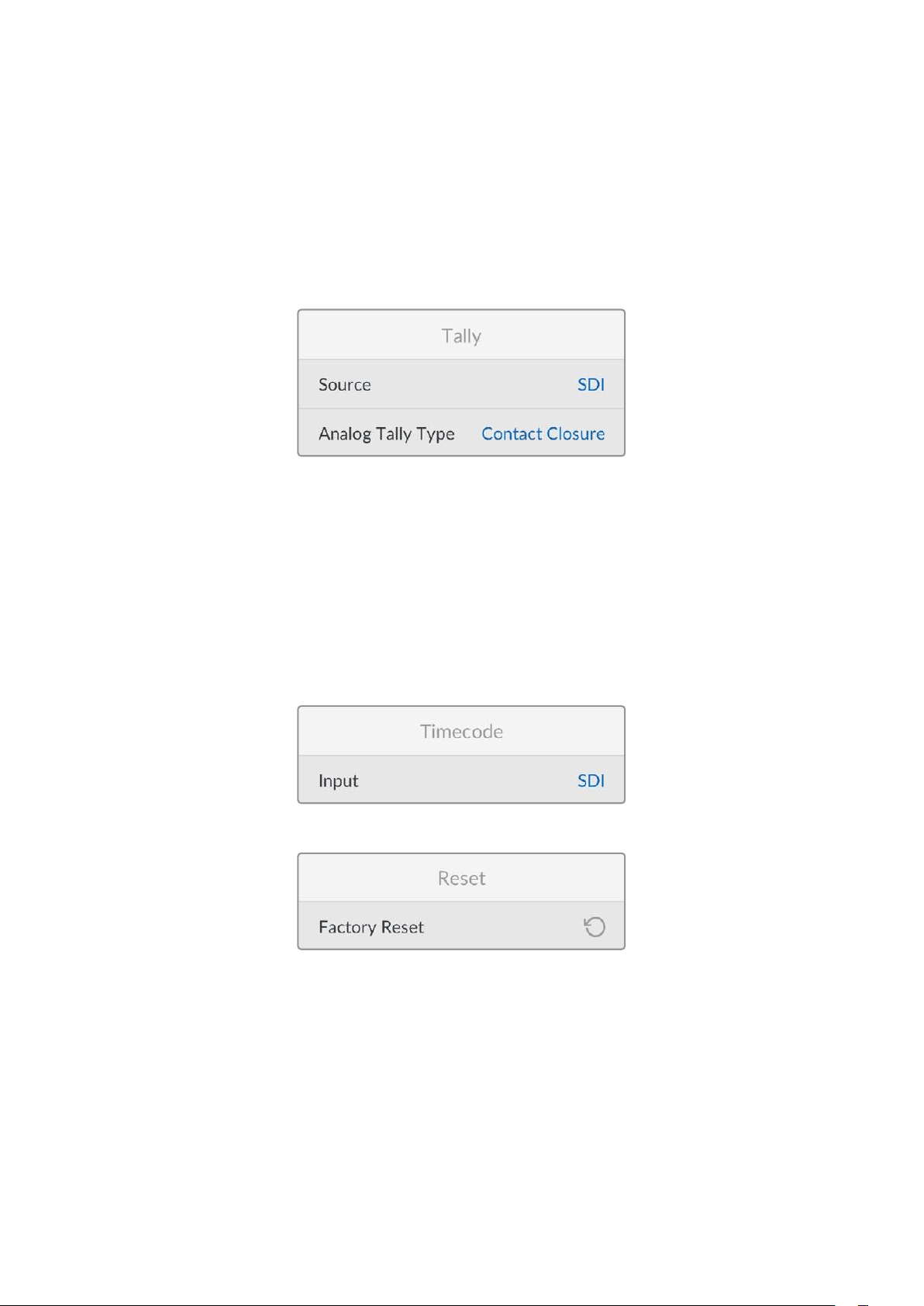
Tally Settings
Source
Select SDI for embedded tally from an ATEM switcher, or ‘analog’ for third party tally systems
connected via the DE-9 serial connector.
Analog Tally Type
Set the analog type to contact closure or voltage depending on the third party tally system
connected via the DE-9 serial connector.
Timecode Settings
Input
There are three timecode input options available.
Auto - When set to ‘auto’ the camera will automatically lock to the external timecode signal
being sent via the return 1 SDI input. If an analog timecode signal is also connected to
Blackmagic Studio Converters timecode input BNC, it will over override the timecode signal
sent via the return 1 SDI input.
Analog - Select analog to manually use analog timecode input.
SDI - Select SDI to manually use return 1 SDI input for your timecode source.
Reset
Factory Reset
‘Factory reset’ restores your Blackmagic Studio Converter to its factory default settings.
Press‘set’ and confirm the setting when prompted.
111Menu Settings
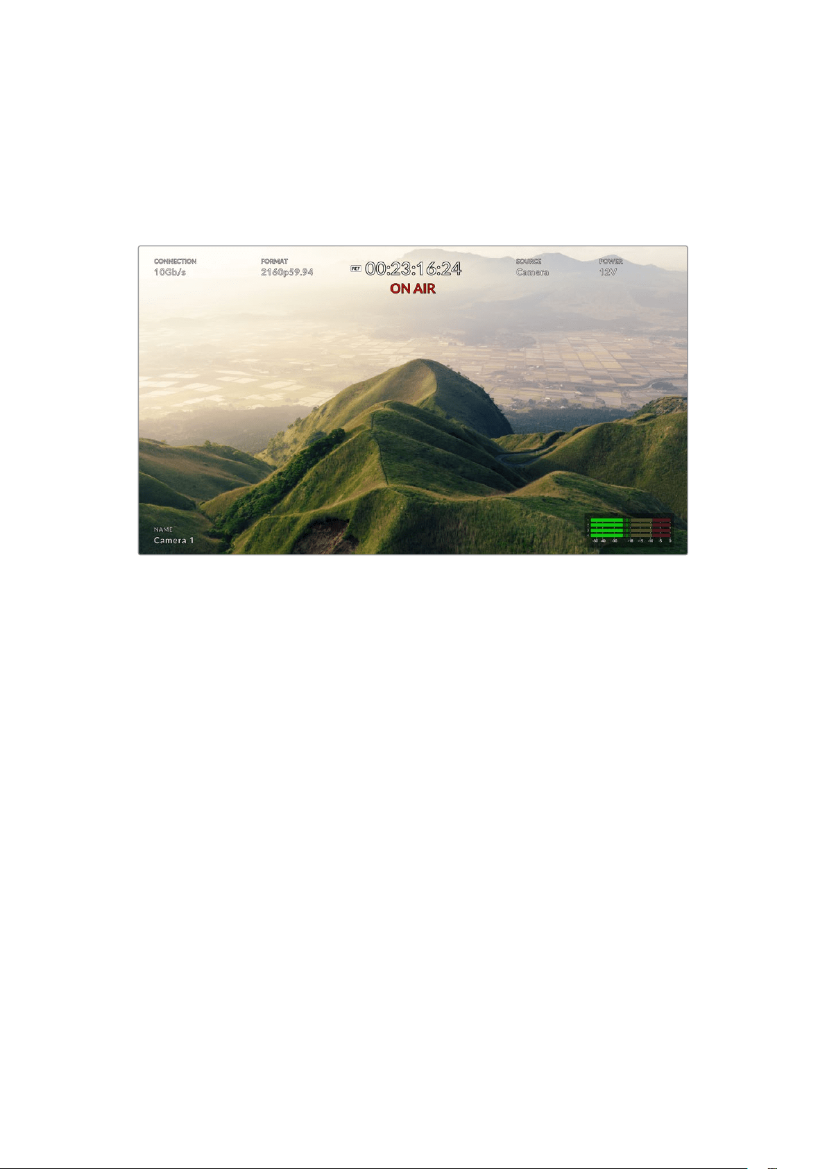
Using the Monitor Output
The monitor output is a fast way to visually check the camera image, plus return 1 and 2, with
overlays displaying important information such as the Ethernet connection type, video format
and frame rate, camera timecode, input source, on air status, PoE status, camera name and
audio levels.
Below is a description of the information displayed.
Connection - Displays the current Ethernet connection type.
Format - Displays the video format of the current source you are viewing.
Reference Icon - Appears when an analog external reference signal is connected.
Timecode - Camera timecode.
Status - Displays when the camera has been switched to the program or preview output on
anATEM switcher.
Source - Displays the current source you are viewing, for example camera, return 1 or return 2.
Camera Power - Displays 12 V when the camera is powered locally, or PoE when powered
over Ethernet.
Name - Displays the ATEM Camera ID of the connected camera.
Audio Meters - Displays the audio meters relevant to the source you are viewing.
112Using the Monitor Output
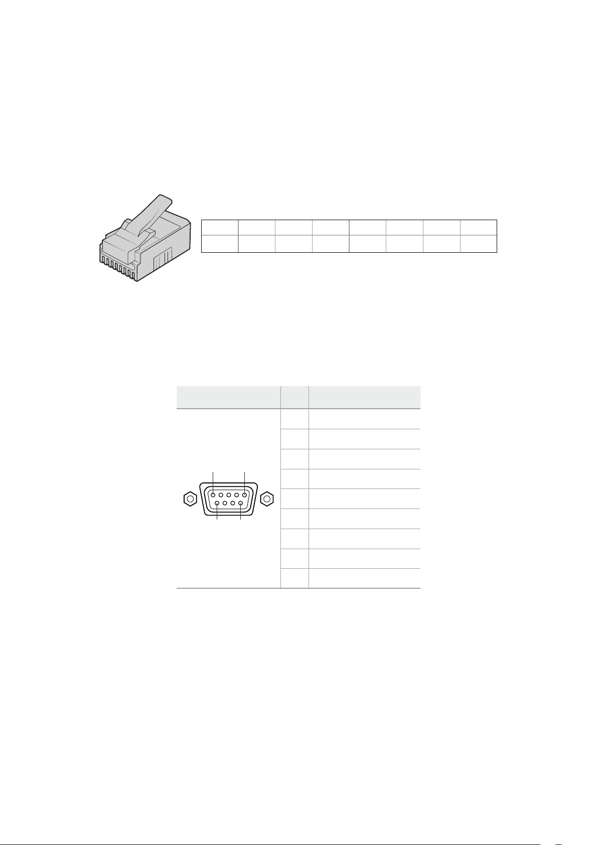
Adapter Cables for Talkback and Tally
Talkback Pin Connections
The ‘talkback’ connector on the back panel of Blackmagic Studio Converter is for routing
engineering talkback and production talkback. You can make an adapter cable with an RJ45
connector using this pinout diagram.
1
2
3
4
5
6
7
8
Eng TX+ Eng TX- Prod TX+ Prod RX+ Prod RX- Prod TX- Eng RX+ Eng RX-
1 2 3 4 5 6 7 8
RJ45 pinout for ‘talkback’ connector on the back panel of Blackmagic Studio Converter.
DB-9 Tally / Audio in connector pinout diagram
The DB-9 tally connector lets you connect to third party tally systems. A pin out diagram is
provided below if you need to build a custom cable.
External view Pin Signal
1
9 6
5
1 PGM Audio in Ch 1 +
2 PGM Audio in Ch 1 -
3 PGM Audio in Ch 2 +
4 PGM Audio in Ch 2 -
5 PGM Audio GND
6 Green tally on/off
7 Green tally ground
8 Red tally on/off
Tally / Audio in connector
9 Red tally ground
113Adapter Cables for Talkback and Tally
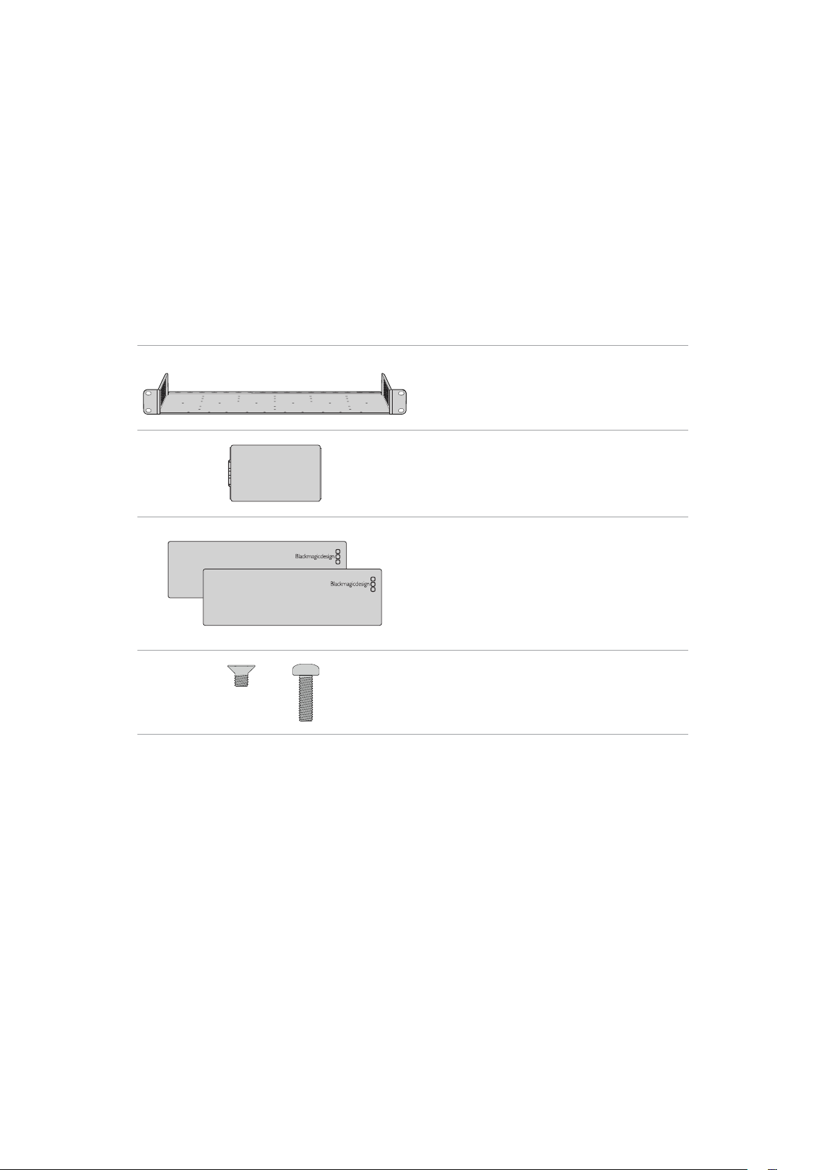
Rack Mounting
Blackmagic Universal Rack Shelf is a 1 rack unit shelf that lets you install Blackmagic Studio
Converter into a broadcast rack or road case.
Blackmagic Studio Converter is small, so you can install it next to other Blackmagic Design
equipment that share a similar form factor, such as HyperDeck Studio HD Plus and Cloud Store
Mini 8TB. For example, installing a Blackmagic HyperDeck Studio HD Mini together with ATEM
1 M/E Constellation HD gives you the ability to switch ten video inputs and record the program
output on your HyperDeck Studio HD Mini. This modular design lets you build your own custom
video solutions that are portable and easy to use.
The Teranex Mini Rack Shelf Kit contains the following:
1 x Blackmagic Universal Rack Shelf
1 x 1/6 rack width blanking panel
Use the 1/6 blanking panel when mounting 1/2 rack
width products with a 1/3 width unit or blanking panel
2 x 1/3 rack width blanking panel
Use 1/3 width blanking panels when mounting single
products
Screws
12 x M3 5mm
Countersunk mounting
screws
2 x M3 9mm
Flat screws for 1/6
blanking panels
Mounting Blackmagic Studio Converter to the Blackmagic Universal Rack Shelf:
1 The first step to mount any product to the Blackmagic Universal Rack Shelf is to remove the
rubber feet from your device.
2 With both the rack and device upside down, line up the pre drilled holes on the rack with
the threaded mounting holes on the device. This will be via two central mounting points on
1/3 width products or up to three mounting points on larger products such as Blackmagic
Studio Converter. The location of the mounting points will depend on whether you are
installing the unit on the left or right of the rack.
114Rack Mounting
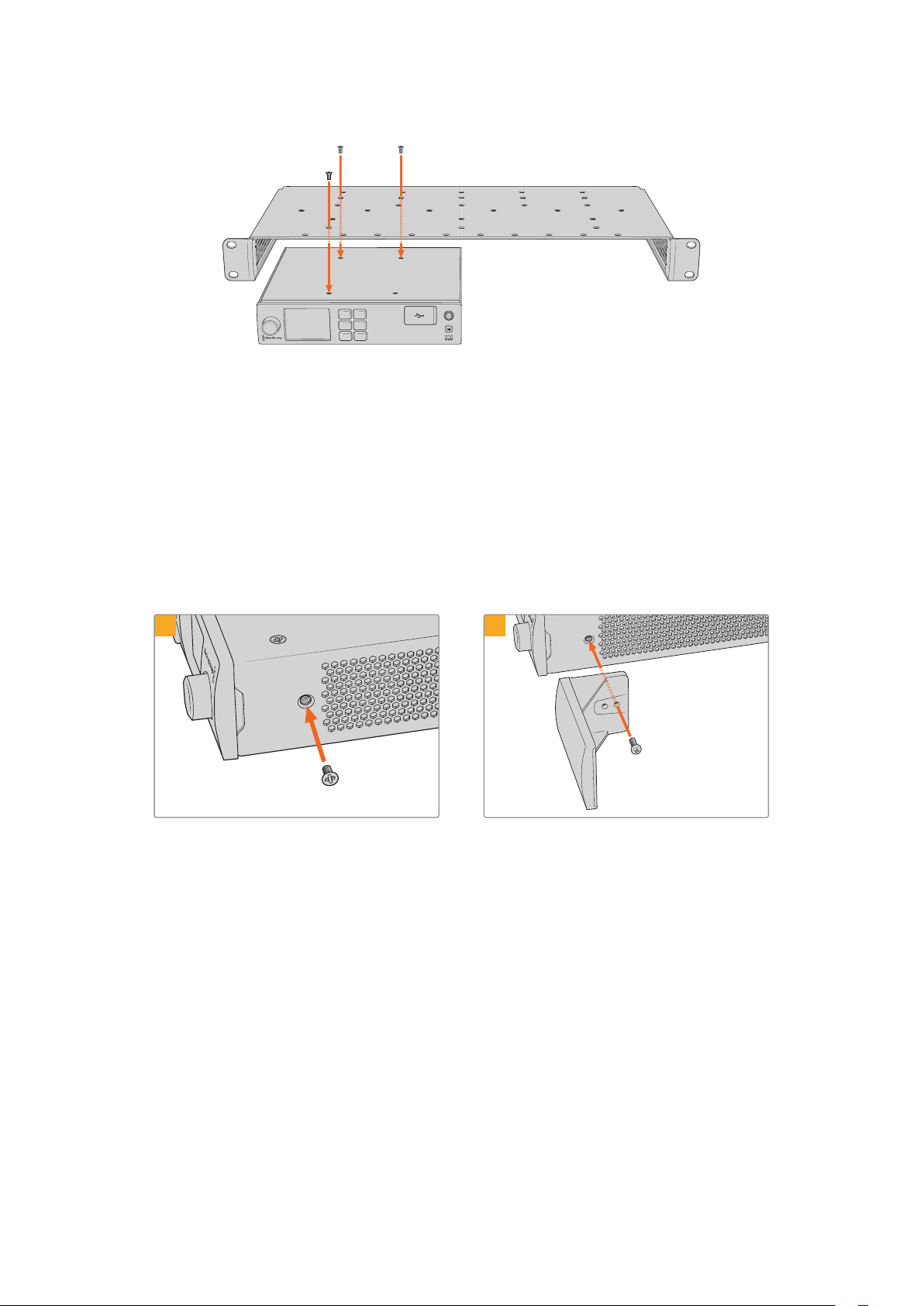
CAM
MENU
RET 1
SET
RET 2
CALL
3 Using the supplied M3 5mm countersunk screws, mount the device to the rack.
4 Once you’ve installed your Blackmagic Studio Converter or other Blackmagic Design
product, turn the rack shelf right side up and install into your equipment rack.
Blanking panels can be used to fill spaces in your rack that may be left available, such as when
mounting a Blackmagic Studio Converter with a Blackmagic Web Presenter.
Attaching the 1/6 blanking panel:
The 1/6 blanking panel is designed to be attached to 1/2 rack width products, such as
Blackmagic Studio Converter when they are mounted solo, or with a 1/3 rack width product
such as a Blackmagic Web Presenter. Mount the panel to the side of the device towards the
centre of the rack to allow for airflow between units.
Remove the 5mm M3 screw near
the front ofthedevice.
Line up the blanking panel and attach using
the supplied M3 10mm nylon screw.
1
2
Attaching the side 1/3 width blanking panel:
To install the 1/3 width blanking panel, line up the screw holes and anchor point with the shelf.
The 1/3 width blanking panel can be used on either side or the center of the rack. Screw the
panel to the shelf using two of the supplied M3 5mm countersunk screws.
Blackmagic Universal Rack Shelf is designed for deeper products, such as Blackmagic Studio
Converter, but can also be used with Teranex Mini converters and HyperDeck Studio products
that aren’t as deep.
115Rack Mounting
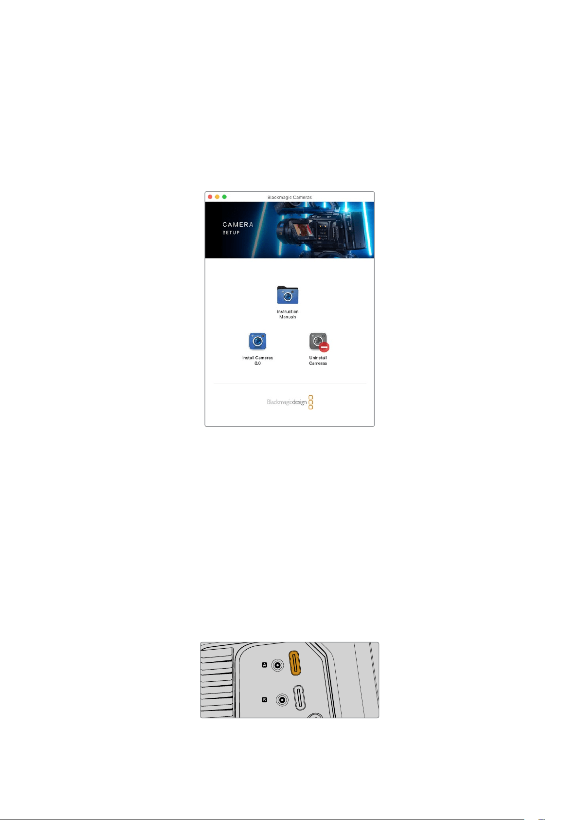
Blackmagic Camera Setup
How to Update Your Camera Software on Mac OS
After downloading the latest Blackmagic Camera Update software from the Blackmagic Design
support center, unzip the downloaded file and double click on the .dmg disk image file.
Launchthe ‘Install Cameras’ installer and follow the onscreen instructions.
How to Update Your Camera Software on Windows
After downloading the ‘Blackmagic Camera Setup’ software and unzipping the downloaded file,
you should see a ‘Blackmagic Camera Setup’ installer window. Double click on the installer icon
and follow the onscreen prompts to complete the installation.
After the installation is complete, click on the Windows ‘start’ menu, and go to ‘all programs’.
Click on the Blackmagic Design folder to open the Blackmagic Camera setup software and
instruction manuals.
How to Update your Camera’s Internal Software
After installing the latest Blackmagic Camera Setup software on your computer, connect a USB
cable from the computer to your camera’s USB-C A port.
Power your camera, launch ‘Blackmagic Camera Setup’ and follow the onscreen prompts to
update the camera software.
USB-C
USB-C
Blackmagic Studio Cameras plug into your computer
via their USB-C expansion port A connector
116
Blackmagic Camera Setup
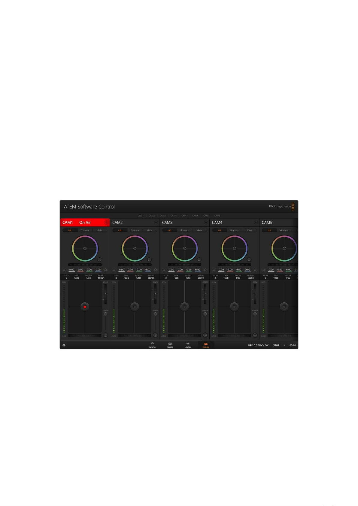
Using ATEM Software Control
Camera Control
Your Blackmagic Studio Camera can be controlled from an ATEM switcher using the Camera
Control feature in ATEM Software Control. Clicking on the ‘camera’ button in ATEM Software
Control opens the camera control feature. Settings such as iris, gain, focus and zoom control
are easily adjusted using compatible lenses, plus you can color balance cameras and create
unique looks using the DaVinci Resolve primary color corrector that’s built into the camera.
On HDMI ATEM switchers, ATEM Software Control automatically detects which camera is
connected to each input, so the tally signals will always trigger the appropriate cameras.
However, if you want to change the button mapping so camera inputs appear on different
buttons, you can do that in the button mapping settings in ATEM Software Control’s
preferences.
On SDI ATEM switchers the camera control data, tally and talkback is sent over the program
return feed to the camera. On SDI models you will need to set the camera numbers manually if
using more than one camera.
ATEM Camera Control
Camera Control Panel
Launch ATEM Software Control and click on the ‘camera’ button located at the bottom of the
software window. You’ll see a row of labeled Blackmagic camera controllers containing tools to
adjust and refine each camera’s image. The controllers are easy to use. Simply click the buttons
using your mouse, or click and drag features to adjust.
Camera Control Selection
The button row at the top of the camera control page lets you select the camera number you
would like to control.
117Using ATEM Software Control
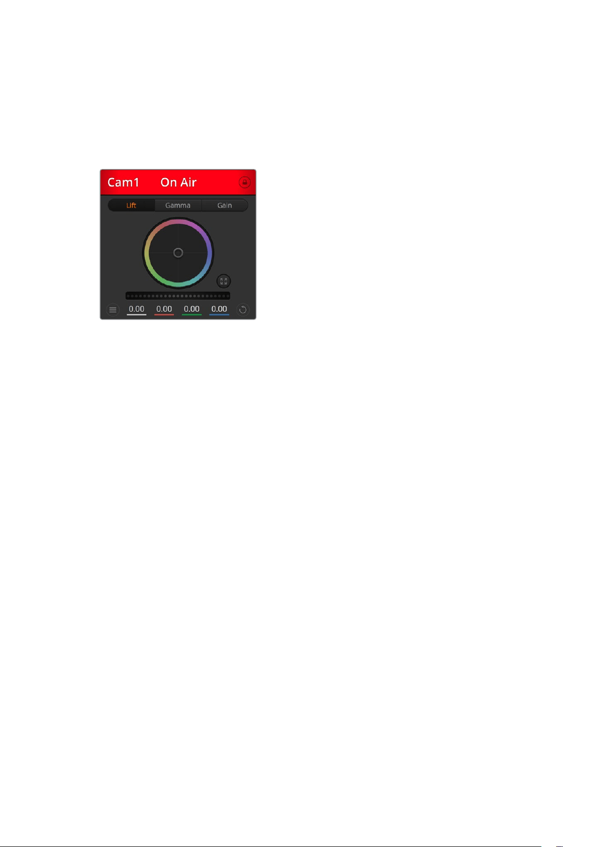
Channel Status
The channel status at the top of each camera controller displays the camera label, On Air
indicator and lock button. Press the lock button to lock all the controls for a specific camera.
When on air, the channel status illuminates red and displays the On Air alert.
Camera Settings
The camera settings button near the bottom left of
the master wheel lets you adjust detail settings for
each camera’s picture signal.
Each camera controller displays the channel status
so you know which camera is on air. Usethecolor
wheels to adjust each YRGB channel’s lift, gamma
and gain settings.
Detail
Use this setting to sharpen the image from your cameras live. Decrease or increase the level
of sharpening by selecting: Detail off, detail default for low sharpening, medium detail and
high detail.
Color Wheel
The color wheel is a powerful feature of the DaVinci Resolve color corrector and used to make
color adjustments to each YRGB channel’s lift, gamma and gain settings. Youcan select which
setting to adjust by clicking on the three selection buttons above the color wheel.
Master Wheel
Use the master wheel below the color wheel to make contrast adjustments to all YRGB
channels at once, or luminance only for each lift, gamma or gain setting.
Reset Buttons
The reset button near the bottom right of each camera controller lets you easily choose color
correction settings to reset, copy or paste. Each color wheel also has its own reset button.
Press to restore a setting to its default state, or copy/paste a setting. Locked controllers are not
affected by the Paste feature. The master reset button on the bottom right corner of the color
corrector panel lets you reset lift, gamma and gain color wheels plus Contrast, Hue, Saturation
and Lum Mix settings. You can paste color correction settings to camera controllers individually,
or all cameras at once for a unified look. Iris, focus, coarse and pedestal settings are not
affected by the Paste feature. When applying Paste to all, a warning message will appear asking
you to confirm your action. This is so you don’t accidentally paste new settings to any unlocked
cameras that are currently on air.
Each camera controller displays the channel
status so you know which camera is on air
118
Using ATEM Software Control
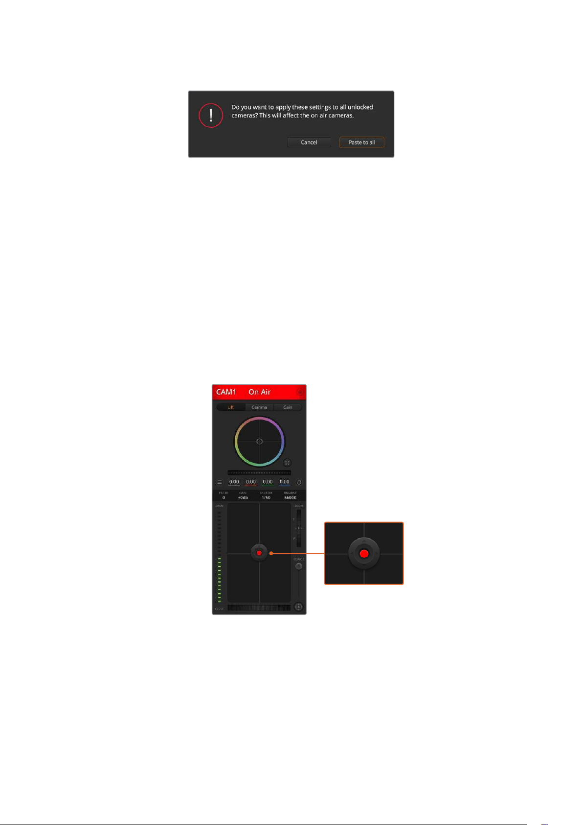
When applying ‘paste to all’, a warning message will appear
asking you to confirm your action
Iris/Pedestal Control
The iris/pedestal control is located within the cross hairs of each camera controller. Thecontrol
illuminates red when its camera is on air.
To open or close the iris, drag the control up or down. Holding the shift key allows only iris
adjustments.
To darken or lift the pedestal, drag the control left or right. Holding the command key on a Mac,
or the Control key on Windows, allows only pedestal adjustments.
Zoom Control
When using compatible lenses with an electronic zoom feature, you can zoom your lens in
and out using the Zoom control. The controller works just like the zoom rocker on a lens, with
telephoto on one end and wide angle on the other. Click on the zoom control, located above
the coarse slider and drag up to zoom in, or drag down to zoom out.
The iris/pedestal control illuminates red
when its respective camera is on air.
Coarse Setting
The coarse setting is located to the right of the iris/pedestal control and is used to limit the iris
range. This feature helps you prevent over exposed images from going to air.
To set your coarse threshold, completely open the iris using the iris control, then drag the
coarse setting up or down to set optimum exposure. Now when you adjust the iris, the coarse
threshold will prevent it from going above optimum exposure.
119Using ATEM Software Control
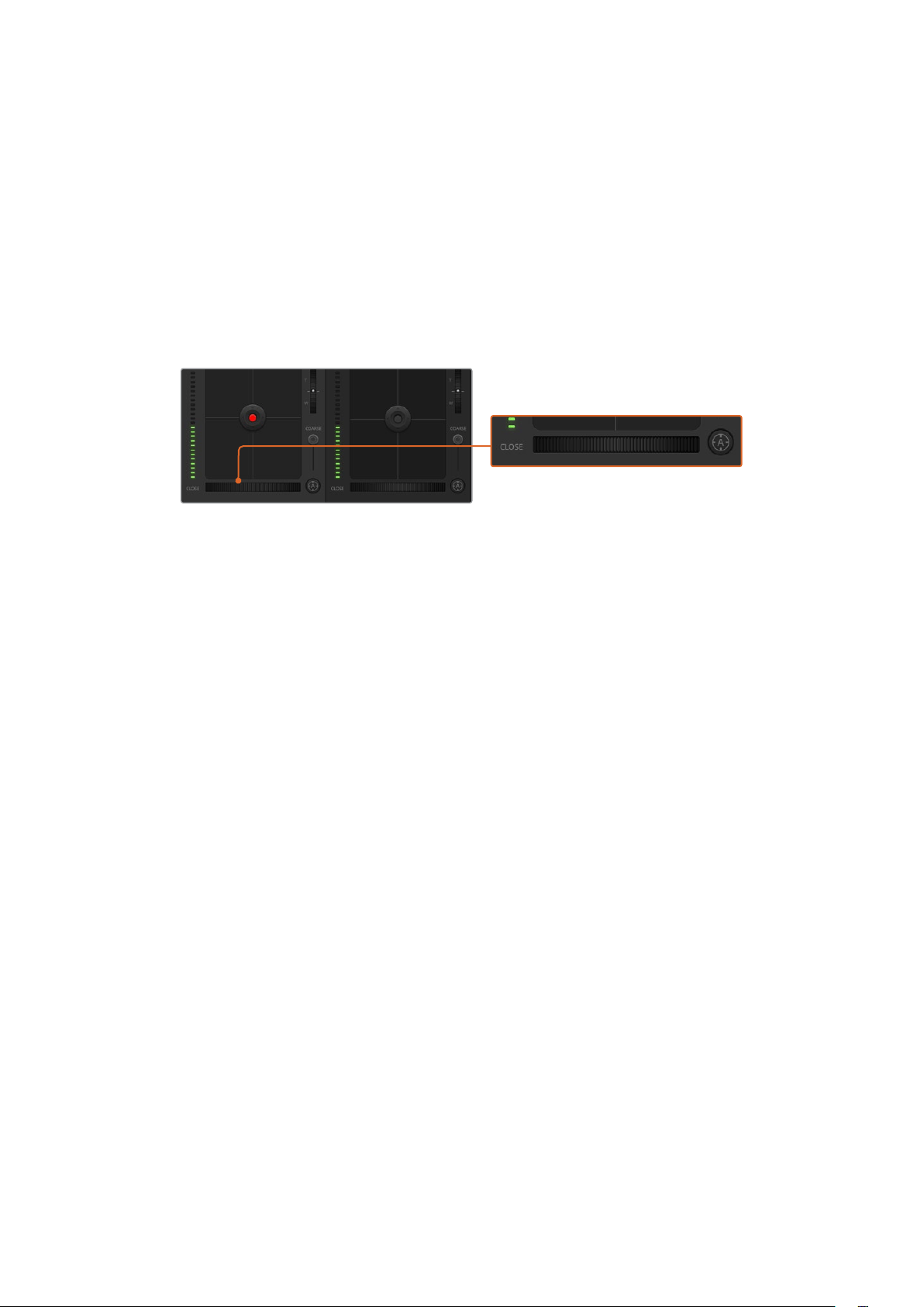
Iris Indicator
The iris indicator is located to the left of the iris/pedestal control and displays a visual reference
so you can easily see how open or closed the lens aperture is. The iris indicator is affected by
the coarse setting.
Auto Focus Button
The auto focus button is located at the bottom right corner of each camera controller. Press
to automatically set the focus when you have an active lens that supports electronic focus
adjustments. It’s important to know that while most lenses support electronic focus, some lenses
can be set to manual or auto focus modes and so you need to ensure your lens is set to auto
focus mode. Sometimes this is set by sliding the focus ring on the lens forward or backward.
Click on the auto focus button or drag the manual focus
adjustment left or right to focus a compatible lens.
Manual Focus Adjustment
When you want to adjust the focus on your camera manually, you can use the focus adjustment
located at the bottom of each camera controller. Drag the wheel control left or right to manually
adjust focus while viewing the video feed from the camera to ensure your image is nice
and sharp.
Filter
The filter control allows you to switch ND filters in Blackmagic Studio Camera 6K Pro. Press the
left or right ND filter buttons to cycle through the options.
Camera Gain
The camera gain setting allows you to turn on additional gain in the camera. On Blackmagic
Studio Cameras, this setting relates to ISO. This is important when you are operating in low light
conditions and need extra gain, or ISO, in the front end of the camera to avoid your images
being under exposed. You can decrease or increase gain by clicking on the left or right arrows
on the dB gain setting.
You can turn on some gain when you need it, such as outdoor shoots when the light fades at
sunset and you need to increase your image brightness. It’s worth noting that adding gain will
increase noise in your images.
Shutter Speed Control
The shutter speed control is located in the section between the color wheel and the iris/
pedestal control. Decrease or increase the shutter speed by hovering your mouse pointer over
the shutter speed indicator and then clicking on the left or right arrows. On Blackmagic Studio
Cameras, this setting relates to shutter speed.
If you see flicker in lights you can decrease your shutter speed to eliminate it. Decreasing
shutter speed is a good way to brighten your images without using camera gain because you
are increasing the exposure time of the image sensor. Increasing shutter speed will reduce
motion blur so can be used when you want action shots to be sharp and clean with minimal
motion blur.
120Using ATEM Software Control
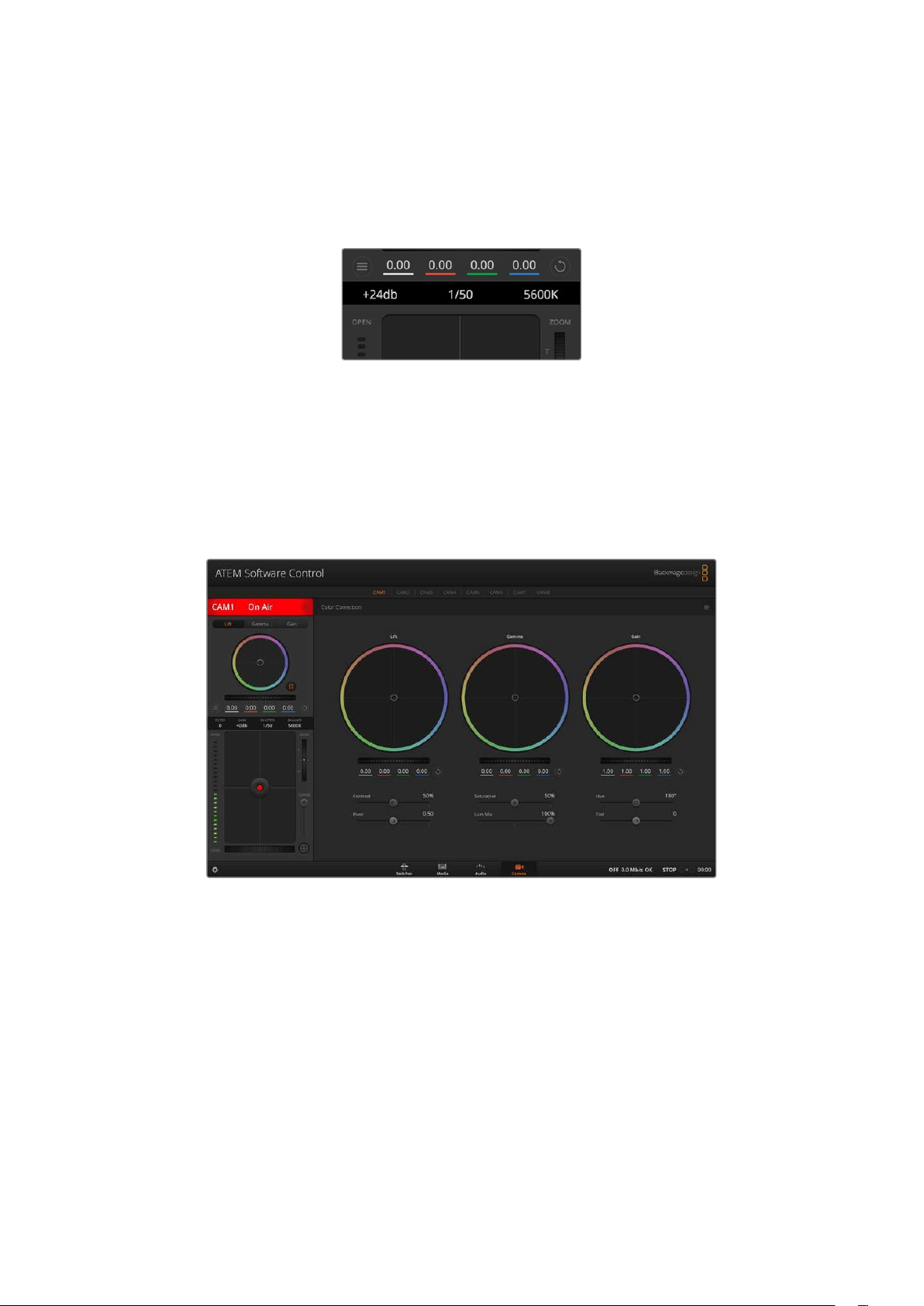
White Balance
The white balance setting next to the shutter speed control can be adjusted by clicking on the
left or right arrows on each side of the color temperature indicator. Different light sources emit
warm or cool colors, so you can compensate by adjusting the white balance. This ensures the
whites in your image stay white.
Hovering your mouse pointer over the gain, shutter
speed and white balance indicators reveal arrows
you can click on to adjust their respective settings
DaVinci Resolve Primary Color Corrector
If you have a color correction background, then you can change your camera control from a
switcher style CCU interface to a user interface that’s more like a primary color corrector on a
post production color grading system.
Click on the DaVinci Resolve primary color corrector button to expand the color correction
window and adjust settings
Blackmagic cameras feature a DaVinci Resolve primary color corrector built in. If you have used
DaVinci Resolve, then creatively, grading in the Blackmagic camera will be identical so you
can use your color grading experience for live production. The color corrector panel can be
expanded out of any camera controller and provides expanded color correction control with
extra settings and a full primary color corrector interface.
You have color wheels and settings such as saturation available and you can see shadows,
midtones and highlight settings all at the same time. Simply switch between cameras using the
camera selection controls at the top of the window as you need.
121Using ATEM Software Control
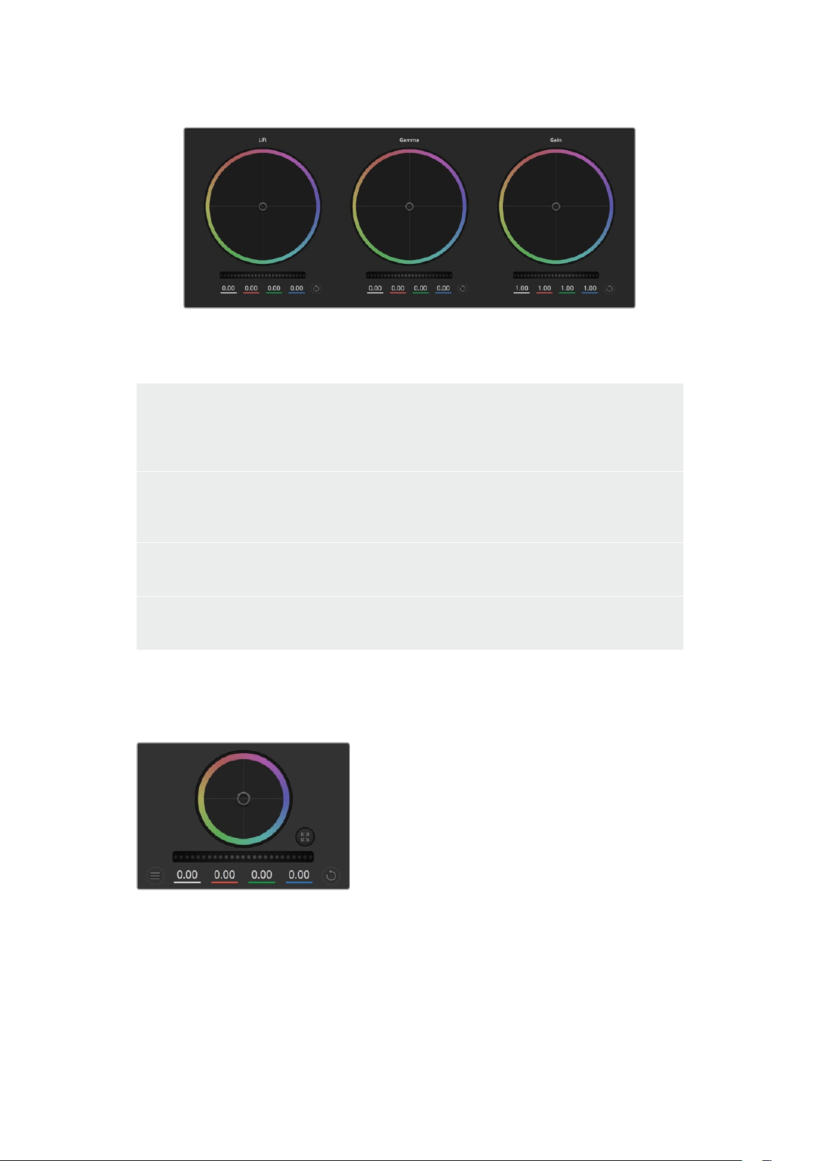
Lift, gamma and gain color wheels in the color corrector panel
Color Wheels
Click and drag anywhere within the color ring
Note that you don’t need to drag the color balance indicator itself. As the color balance
indicatormoves, the RGB parameters underneath change to reflect the adjustments being made
toeach channel.
Shift-Click and drag within the color ring
Jumps the color balance indicator to the absolute position of the pointer, letting you make faster
andmore extreme adjustments.
Double-click within the color ring
Resets the color adjustment without resetting the master wheel adjustment for that control.
Click the reset control at the upper-right of a color ring
Resets both the color balance control and its corresponding masterwheel.
Master Wheels
Use the master wheels below the color wheels to adjust each YRGB channels’ lift, gamma and
gain controls.
Dragging to the left darkens the selected parameter
of the image, dragging to the right lightens that
parameter. As you make an adjustment, the
YRGB parameters underneath change to reflect
the adjustment you’re making. To make a Y-only
adjustment, hold down the ALT or Command key and
drag left or right. Because the color corrector uses
YRGB processing, you can get quite creative and
create unique affects by adjusting the Y channel only.
Y channel adjustments work best when the Lum Mix
setting is set to the right side to use YRGB processing
vs the left side to use regular RGB processing.
Normally, most DaVinci Resolve colorists use the YRGB color corrector as you get a lot more
control of color balance without affecting overall gain, so you spend less time getting the
look you want.
Adjust the master wheels by dragging
the wheel control left or right
122
Using ATEM Software Control

Contrast Setting
The Contrast setting gives you control over the distance between the darkest and lightest
values of an image. The effect is similar to making opposing adjustments using the lift and gain
master wheels. The default setting is 50%. Using the Pivot Control, the pivot points can be
moved up and down on the S-curve. When working with log images like the Gen 5 Film curve,
after performing white balance and setting exposure, adjusting the contrast and pivot can very
quickly get you to a good starting point with your color grade.
Saturation Setting
The Saturation setting increases or decreases the amount of color in the image. The default
setting is 50%.
Hue Setting
The Hue setting rotates all hues of the image around the full perimeter of the color wheel.
Thedefault setting of 180 degrees shows the original distribution of hues. Raising or lowering
this value rotates all hues forward or backward along the hue distribution as seen on a
color wheel.
Lum Mix Setting
The color corrector built into Blackmagic cameras is based on the DaVinci Resolve primary
color corrector. DaVinci has been building color correctors since the early 1980’s and most
Hollywood films are color graded on DaVinci Resolve than any other method.
This means that your color corrector built into the camera has some unique and creatively
powerful features. The YRGB processing is one of those features.
When color grading, you can choose to use RGB processing, or YRGB processing. High end
colorists use YRGB processing because you have more precise control over color and you can
independently adjust the channels with better separation and more creative options.
When the Lum Mix control is set to the right side, you have the 100% output of the YRGB color
corrector. When you have the Lum Mix control set to the left side, you get 100% output of the
RGB corrector. You can set the Lum Mix to any position between theleft and right to get a blend
of output from both the RGB and YRGB correctors.
Which is the correct setting to use? That’s up to you, as color correction is a pure creative
process and there is no right and wrong. The best setting is what you like the most and what
you think looks good!
Pivot Setting
Once the contrast setting is adjusted, modifying the pivot value will adjust the midpoint of
thecontrast. The Pivot control establishes the contrast balance by placing more or less
priority on either side of the luminance scale. By lifting the control, you will increase the
overallbrightness and clarity of the image, although at the inverse expense of the shadows,
which willbe reduced.
123Using ATEM Software Control

Tint Setting
Adjusting the tint setting will add green or magenta to the image to help balance the color.
Thiscan assist when filming with artificial lighting sources such as fluorescent and sodium
vapor lighting fixtures.
Drag the sliders left or right to adjust Contrast, Saturation, Hue and Lum Mix settings
Synchronizing Settings
When connected, camera control signals are sent from your ATEM switcher to the Blackmagic
camera. If a setting is accidentally adjusted from your camera, camera control will automatically
reset that setting to maintain synchronization.
124Using ATEM Software Control

Developer Information
Blackmagic SDI Camera Control Protocol
Version 1.6.2
If you are a software developer you can use the Blackmagic SDI to construct devices that integrate
with our products. Here at Blackmagic Design, our approach is to open up our protocols and we
eagerly look forward to seeing what you come up with!
Overview
This document describes an extensible protocol for sending a unidirectional stream of small control
messages embedded in the non-active picture region of a digital video stream. The video stream
containing the protocol stream may be broadcast to a number of devices. Device addressing is used
to allow the sender to specify which device each message is directed to.
Assumptions
Alignment and padding constraints are explicitly described in the protocol document. Bit fields are
packed from LSB first. Message groups, individual messages and command headers are defined as,
and can be assumed to be, 32 bit aligned.
Blanking Encoding
A message group is encoded into a SMPTE 291M packet with DID/SDID x51/x53 in the active region
of VANC line 16.
Message Grouping
Up to 32 messages may be concatenated and transmitted in one blanking packet up to a maximum
of 255 bytes payload. Under most circumstances, this should allow all messages to be sent with a
maximum of one frame latency.
If the transmitting device queues more bytes of message packets than can be sent in a single frame,
it should use heuristics to determine which packets to prioritize and send immediately. Lower priority
messages can be delayed to later frames, or dropped entirely as appropriate.
Abstract Message Packet Format
Every message packet consists of a three byte header followed by an optional variable length data
block. The maximum packet size is 64 bytes.
Destination device (uint8)
Device addresses are represented as an 8 bit unsigned integer. Individual
devices are numbered 0 through 254 with the value 255reserved to
indicate a broadcast message to all devices.
Command length (uint8)
The command length is an 8 bit unsigned integer which specifies the
length of the included command data. The length does NOT include
the length of the header or any trailing padding bytes.
Command id (uint8)
The command id is an 8 bit unsigned integer which indicates themessage
type being sent. Receiving devices should ignore any commands that they
do not understand. Commands 0 through 127 are reserved for commands
that apply to multiple types of devices. Commands 128 through 255 are
device specific.
125Developer Information

Reserved (uint8)
This byte is reserved for alignment and expansion purposes. It should
be set tozero.
Command data (uint8[])
The command data may contain between 0 and 60 bytes of data.
The format of the data section is defined by the command itself.
Padding (uint8[])
Messages must be padded up to a 32 bit boundary with 0x0bytes.
Anypadding bytes are NOT included in the command length.
Receiving devices should use the destination device address and or the command identifier to
determine which messages to process. The receiver should use the command length to skip
irrelevant or unknown commands and should be careful to skip the implicit padding as well.
Defined Commands
Command 0 : change configuration
Category (uint8)
The category number specifies one of up to 256 configuration categories
available on the device.
Parameter (uint8)
The parameter number specifies one of 256 potential configuration
parameters available on the device. Parameters 0 through 127 are
device specific parameters. Parameters 128 though 255 are reserved
for parameters that apply to multiple types of devices.
Data type (uint8)
The data type specifies the type of the remaining data. Thepacket length
is used to determine the number of elements in the message. Each
message must contain an integral number of data elements.
Currently defined values are:
0: void/boolean
A void value is represented as a boolean array of length zero.
The data field is a 8 bit value with 0 meaning false and all other
values meaning true.
1: signed byte Data elements are signed bytes
2: signed 16bit integer Data elements are signed 16 bit values
3: signed 32bit integer Data elements are signed 32 bit values
4: signed 64bit integer Data elements are signed 64 bit values
5: UTF-8 string Data elements represent a UTF-8 string with no terminating character.
Data types 6 through 127 are reserved.
128: signed 5.11fixed
point
Data elements are signed 16 bit integers representing a real number with
5bits for the integer component and 11 bits for the fractional component.
Thefixed point representation is equal to the real value multiplied by 2^11.
The representable range is from -16.0 to 15.9995 (15 + 2047/2048).
126Developer Information

Data types 129 through 255 are available for device specific purposes.
Operation type (uint8)
The operation type specifies what action to perform on the specified
parameter. Currently defined values are:
0: assign value
The supplied values are assigned to the specified parameter. Each
element will be clamped according to its valid range. A void parameter
may only be ‘assigned’ an empty list of boolean type. This operation will
trigger the action associated with that parameter. A boolean value may be
assigned the value zero for false, and any other value for true.
1: offset/toggle value
Each value specifies signed offsets of the same type to be added to the
current parameter values. The resulting parameter value will be clamped
according to their valid range. It is not valid to apply an offset to a void
value. Applying any offset other than zero to a boolean value will invert
that value.
Operation types 2 through 127 are reserved.
Operation types 128through 255 are available for device specific purposes.
Data (void)
The data field is 0 or more bytes as determined by the data type and
number of elements.
The category, parameter, data type and operation type partition a 24 bit operation space.
Group ID Parameter Type Index Minimum Maximum Interpretation
Lens
0.0 Focus fixed16 – 0.0 1.0 0.0 = near, 1.0 = far
0.1 Instantaneous autofocus void – – – trigger instantaneous autofocus
0.2 Aperture (f-stop) fixed16 – -1.0 16.0
Aperture Value (where fnumber
= sqrt(2^AV))
0.3 Aperture (normalised) fixed16 – 0.0 1.0 0.0 = smallest, 1.0 = largest
0.4 Aperture (ordinal) int16 – 0 n
Steps through available
aperture values from minimum
(0) to maximum (n)
0.5
Instantaneous auto
aperture
void – – –
trigger instantaneous auto
aperture
0.6 Optical image stabilisation boolean – – – true = enabled, false = disabled
0.7 Set absolute zoom (mm) int16 – 0 max
Move to specified focal length
in mm, from minimum (0) to
maximum (max)
0.8
Set absolute zoom
(normalised)
fixed16 – 0.0 1.0
Move to specified focal length:
0.0 = wide, 1.0 = tele
0.9
Set continuous zoom
(speed)
fixed16 – -1.0 +1.0
Start/stop zooming at specified
rate: -1.0 = zoom wider fast, 0.0
= stop,
+1 = zoom tele fast
127Developer Information

Group ID Parameter Type Index Minimum Maximum Interpretation
Video
1.0 Video mode int8
[0] = frame rate – –
fps as integer
(eg 24, 25, 30, 50, 60)
[1] = M-rate – – 0 = regular, 1 = M-rate
[2] = dimensions – –
0 = NTSC, 1 = PAL, 2 = 720,
3 = 1080, 4 = 2kDCI, 5 = 2k16:9,
6 = UHD, 7 = 3k Anamorphic,
8 = 4k DCI, 9 = 4k 16:9,
10 = 4.6k 2.4:1, 11 = 4.6k
[3] = interlaced – – 0 = progressive, 1 = interlaced
[4] = Color space – – 0 = YUV
1.1 Gain (up to Camera 4.9) int8 1 128
1x, 2x, 4x, 8x, 16x, 32x, 64x, 128x
gain
1.2 Manual White Balance
int16 [0] = color temp 2500 10000 Color temperature in K
int16 [1] = tint -50 50 tint
1.3 Set auto WB void – – –
Calculate and set autowhite
balance
1.4 Restore auto WB void – – –
Use latest auto white balance
setting
1.5 Exposure (us) int32 1 42000 time in us
1.6 Exposure (ordinal) int16 – 0 n
Steps through available
exposure valuesfrom minimum
(0) tomaximum (n)
1.7 Dynamic Range Mode int8 enum – 0 2
0 = film, 1 = video,
2 = extended video
1.8 Video sharpening level int8 enum – 0 3
0 = off, 1 = low, 2= medium,
3 = high
1.9 Recording format int16
[0] = file frame rate – –
fps as integer
(eg 24, 25, 30, 50, 60, 120)
[1] = sensor frame
rate
– –
fps as integer, valid when
sensor-off-speed set (eg 24,
25, 30, 33, 48, 50, 60, 120),
no change will beperformed
if this value is set to 0
[2] = frame width – – in pixels
[3] = frame height – – in pixels
[4] = flags
– – [0] = file-M-rate
– –
[1] = sensor-M-rate, valid
whensensor-off-speed-set
– – [2] = sensor-off-speed
– – [3] = interlaced
– – [4] = windowed mode
1.10 Set auto exposure mode int8 – 0 4
0 = Manual Trigger, 1 = Iris,
2 = Shutter, 3 = Iris + Shutter,
4 = Shutter + Iris
1.11 Shutter angle int32 – 100 36000
Shutter angle in degrees,
multiplied by 100
1.12 Shutter speed int32 –
Current
sensor
frame rate
5000
Shutter speed value as a
fraction of 1, so 50 for 1/50th
of a second
1.13 Gain int8 – -128 127 Gain in decibel (dB)
1.14 ISO int32 – 0 2147483647 ISO value
1.15 Display LUT int8
[0] = selected LUT – –
0 = None, 1 = Custom,
2 = film to video,
3 = film to extended video
[1] = enabled or not – – 0 = Not enabled, 1 = Enabled
1.16 ND Filter Stop fixed16
[0] = stop 0.0 15.0 filter power, as f-stop
[1] = display mode – –
0 = stop
1 = density
2 = transmittance
128Developer Information

Group ID Parameter Type Index Minimum Maximum Interpretation
Audio
2.0 Mic level fixed16 – 0.0 1.0 0.0 = minimum, 1.0 = maximum
2.1 Headphone level fixed16 – 0.1 1.0 0.0 = minimum, 1.0 = maximum
2.2 Headphone program mix fixed16 – 0.1 1.0 0.0 = minimum, 1.0 = maximum
2.3 Speaker level fixed16 – 0.1 1.0 0.0 = minimum, 1.0 = maximum
2.4 Input type int8 – 0 3
0 = internal mic,
1 = line level input,
2 = low mic level input,
3 = high mic level input
2.5 Input levels fixed16
[0] ch0 0.0 1.0 0.0 = minimum, 1.0 = maximum
[1] ch1 0.0 1.0 0.0 = minimum, 1.0 = maximum
2.6 Phantom power boolean – – –
true = powered,
false = not powered
Output
3.0
Overlay enables
uint16
bit field
[0] = bit field – –
bit flags:
[0] = display status,
[1] = display frame guides
[2] = clean feed
Some cameras don’t allow
separate control of frame
guides and status overlays.
uint16
bit field
[1] = target displays
bit field
– –
bit flags:
[0] = LCD
[1] = HDMI
[2] = EVF
[3] = Main SDI
[4] = Front SDI
3.1
Frame guides style (Camera
3.x)
int8 – 0 8
0 = HDTV, 1 = 4:3, 2 = 2.4:1,
3 = 2.39:1, 4 = 2.35:1,
5 = 1.85:1, 6 = thirds
3.2
Frame guides opacity
(Camera 3.x)
fixed16 – 0.1 1.0 0.0 = transparent, 1.0 = opaque
3.3
Overlays
(replaces .1 and .2
abovefrom
Cameras 4.0)
int8
[0] = frame guides
style
– –
0 = off, 1 = 2.4:1, 2 = 2.39:1,
3 = 2.35:1, 4 = 1.85:1, 5 = 16:9,
6 = 14:9, 7 = 4:3, 8 = 2:1,
9 = 4:5, 10 = 1:1
[1] = frame guide
opacity
0 100 0 = transparent, 100 = opaque
[2] = safe area
percentage
0 100
percentage of full frame
used by safe area guide
(0 means off)
[3] = grid style – –
bit flags:
[0] = display thirds,
[1] = display cross hairs,
[2] = display center dot,
[3] = display horizon
129Developer Information

Group ID Parameter Type Index Minimum Maximum Interpretation
Display
4.0 Brightness fixed16 – 0.0 1.0 0.0 = minimum, 1.0 = maximum
4.1
Exposure and focus tools
uint16
bit field
[0] = bit field – –
bit flags:
[0] = Zebra
[1] = Focus Assist
[2] = False Color
uint16
bit field
[1] = target displays
bit field
– –
bit flags:
[0] = LCD
[1] = HDMI
[2] = EVF
[3] = Main SDI
[4] = Front SDI
4.2 Zebra level fixed16 – 0.0 1.0 0.0 = minimum, 1.0 = maximum
4.3 Peaking level fixed16 – 0.0 1.0 0.0 = minimum, 1.0 = maximum
4.4 Color bar enable int8 – 0 30
0 = disable bars,
1-30 = enable bars with timeout
(seconds)
4.5 Focus Assist int8
[0] = focus assist
method
– –
0 = Peak,
1 = Colored lines
[1] = focus line color – –
0 = Red,
1 = Green,
2 = Blue,
3 = White,
4 = Black
4.6 Program return feed enable int8 – 0 30
0 = disable, 1-30 = enable with
timeout (seconds)
4.7 Timecode Source
signed
byte
[0] = source – –
0 = Clip,
1 = Timecode
Tally
5.0 Tally brightness fixed16 – 0.0 1.0
Sets the tally front and tally rear
brightness to the same level.
0.0 = minimum,
1.0 = maximum
5.1 Front tally brightness fixed16 – 0.0 1.0
Sets the tally front brightness.
0.0 = minimum,
1.0 = maximum
5.2 Rear tally brightness fixed16 – 0.0 1.0
Sets the tally rear brightness.
0.0 = minimum,
1.0 = maximum
Tally rear brightness cannot be
turned off
Reference
6.0 Source int8 enum – 0 2
0 = internal,
1 = program,
2 = external
6.1 Offset int32 – – – +/- offset in pixels
130Developer Information

Group ID Parameter Type Index Minimum Maximum Interpretation
Confi-
guration
7.0 Real Time Clock int32
[0] time _ _ BCD - HHMMSSFF (UCT)
[1] date _ _ BCD - YYYYMMDD
7.1 System language string [0-1] _ _
ISO-639-1 two character
language code
7.2 Timezone int32 _ _ _ Minutes offset from UTC
7.3 Location int64
[0] latitude _ _
BCD - s0DDdddddddddddd
where s is the sign:
0 = north (+), 1 = south (-);
DD degrees, dddddddddddd
decimal degrees
[1] longitude _ _
BCD - sDDDdddddddddddd
where s is the sign: 0 = west
(-), 1 = east (+); DDD degrees,
dddddddddddd decimal
degrees
Color
Correction
8.0 Lift Adjust fixed16
[0] red -2.0 2.0 default 0.0
[1] green -2.0 2.0 default 0.0
[2] blue -2.0 2.0 default 0.0
[3] luma -2.0 2.0 default 0.0
8.1 Gamma Adjust fixed16
[0] red -4.0 4.0 default 0.0
[1] green -4.0 4.0 default 0.0
[2] blue -4.0 4.0 default 0.0
[3] luma -4.0 4.0 default 0.0
8.2 Gain Adjust fixed16
[0] red 0.0 16.0 default 1.0
[1] green 0.0 16.0 default 1.0
[2] blue 0.0 16.0 default 1.0
[3] luma 0.0 16.0 default 1.0
8.3 Offset Adjust fixed16
[0] red -8.0 8.0 default 0.0
[1] green -8.0 8.0 default 0.0
[2] blue -8.0 8.0 default 0.0
[3] luma -8.0 8.0 default 0.0
8.4 Contrast Adjust fixed16
[0] pivot 0.0 1.0 default 0.5
[1] adj 0.0 2.0 default 1.0
8.5 Luma mix fixed16 – 0.0 1.0 default 1.0
8.6 Color Adjust fixed16
[0] hue -1.0 1.0 default 0.0
[1] sat 0.0 2.0 default 1.0
8.7 Correction Reset Default void – – – reset to defaults
131Developer Information

Group ID Parameter Type Index Minimum Maximum Interpretation
Media
10.0 Codec int8 enum
[0] = basic codec – –
0 = CinemaDNG,
1 = DNxHD,
2 = ProRes,
3 = Blackmagic RAW
[1] = code variant
– –
CinemaDNG:
0 = uncompressed,
1 = lossy 3:1,
2 = lossy 4:1
– –
ProRes:
0 = HQ,
1 = 422,
2 = LT,
3 = Proxy,
4 = 444,
5 = 444XQ
– –
Blackmagic RAW:
0 = Q0,
1 = Q5,
2 = 3:1,
3 = 5:1,
4 = 8:1,
5 = 12:1
10.1 Transport mode int8
[0] = mode – –
0 = Preview,
1 = Play,
2 = Record
[1] = speed – –
-ve = multiple speeds
backwards,
0 = pause,
+ve = multiple speeds forwards
[2] = flags – –
1<<0 = loop,
1<<1 = play all,
1<<5 = disk1 active,
1<<6 = disk2 active,
1<<7 = time-lapse recording
[3] = slot 1 storage
medium
– –
0 = CFast card,
1 = SD,
2 = SSD Recorder
[4] = slot 2 storage
medium
– –
0 = CFast card,
1 = SD,
2 = SSD Recorder
10.2 Playback Control int8 enum [0] = clip – –
0 = Previous,
1 = Next
10.5 Stream bool [0] = enabled – –
true = enabled,
false = disabled
10.6 Stream Information void bool [0] = enabled – –
true = enabled,
false = disabled
10.7 Stream Display 3D LUT void bool [0] = enabled – –
true = enabled,
false = disabled
132Developer Information

Group ID Parameter Type Index Minimum Maximum Interpretation
PTZ
Control
11.0 Pan/Tilt Velocity fixed 16
[0] = pan velocity -1.0 1.0
-1.0 = full speed left,
1.0 = full speed right
[1] = tilt velocity -1.0 1.0
-1.0 = full speed down,
1.0 = full speed up
11.1 Memory Preset
int8
enum
[0] = preset
command
– –
0 = reset,
1 = store location,
2 = recall location
int8
[1] =
preset slot
0 5 –
133Developer Information
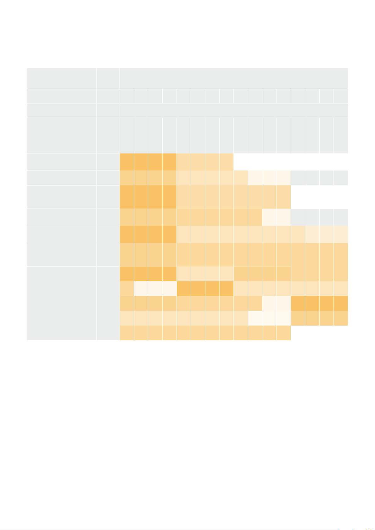
Example Protocol Packets
Operation
Packet
Length Byte
0 1 2 3 4 5 6 7 8 9 10 11 12 13 14 15
header command data
destination
length
command
reserved
category
parameter
type
operation
trigger instantaneous
auto focus on camera 4
8 4 4 0 0 0 1 0 0
turn on OIS on all cameras 12 255 5 0 0 0 6 0 0 1 0 0 0
set exposure to 10 ms on
camera 4 (10 ms = 10000
us = 0x00002710)
12 4 8 0 0 1 5 3 0 0x10 0x27 0x00 0x00
add 15% to zebra level
(15 % = 0.15 f = 0x0133 fp)
12 4 6 0 0 4 2 128 1 0x33 0x01 0 0
select 1080p 23.98 mode on
all cameras
16 255 9 0 0 1 0 1 0 24 1 3 0 0 0 0 0
subtract 0.3 from gamma
adjust for green & blue
(-0.3 ~= 0xfd9a fp)
16 4 12 0 0 8 1 128 1 0 0 0x9a 0xfd 0x9a 0xfd 0 0
all operations combined 76
4 4 0 0 0 1 0 0 255 5 0 0 0 6 0 0
1 0 0 0 4 8 0 0 1 5 3 0 0x10 0x27 0x00 0x00
4 6 0 0 4 2 128 1 0x33 0x01 0 0 255 9 0 0
1 0 1 0 24 1 3 0 0 0 0 0 4 12 0 0
8 1 128 1 0 0 0x9a 0xfd 0x9a 0xfd 0 0
134Developer Information

Blackmagic Embedded Tally Control Protocol
Version 1.0 (30/04/10)
This section is for third party developers or anybody who may wish to add support for the
Blackmagic Embedded Tally Control Protocol to their products or system. It describes the
protocol for sending tally information embedded in the non-active picture region of a digital
video stream.
Data Flow
A master device such as a broadcast switcher embeds tally information into its program feed
which is broadcast to a number of slave devices such as cameras or camera controllers. The
output from the slave devices is typically fed back to the master device, but may also be sent to
a video monitor.
The primary flow of tally information is from the master device to the slaves. Each slave device
may use its device id to extract and display the relevant tally information.
Slave devices pass through the tally packet on their output and update the monitor tally status,
so that monitor devices connected to that individual output may display tally status without
knowledge of the device id they are monitoring.
Assumptions
Any data alignment / padding is explicit in the protocol. Bit fields are packed from LSB first.
Blanking Encoding
One tally control packet may be sent per video frame. Packets are encoded as a SMPTE 291M
packet with DID/SDID x51/x52 in the active region of VANC line 15. A tally control packet may
contain up to 256 bytes of tally information.
Packet Format
Each tally status consist of 4 bits of information:
uint4
bit 0: program tally status (0=off, 1=on)
bit 1: preview tally status (0=off, 1=on)
bit 2-3: reserved (0x0)
The first byte of the tally packet contains the monitor device tally status and a version number.
Subsequent bytes of the tally packet contain tally status for pairs of slave devices. The
master device sends tally status for the number of devices configured/supported, up to a
maximum of 510.
struct tally
uint8
bit 0: monitor device program tally status (0=off, 1=on)
bit 1: monitor device preview tally status (0=off, 1=on)
bit 2-3: reserved (0b00)
bit 4-7: protocol version (0b0000)
uint8[0]
bit 0: slave device 1 program tally status (0=off, 1=on)
bit 1: slave device 1 device preview tally status (0=off, 1=on)
bit 2-3: reserved (0b00)
bit 4: slave device 2 program tally status (0=off, 1=on)
bit 5: slave device 2 preview tally status (0=off, 1=on)
bit 6-7: reserved (0b00)
135Developer Information
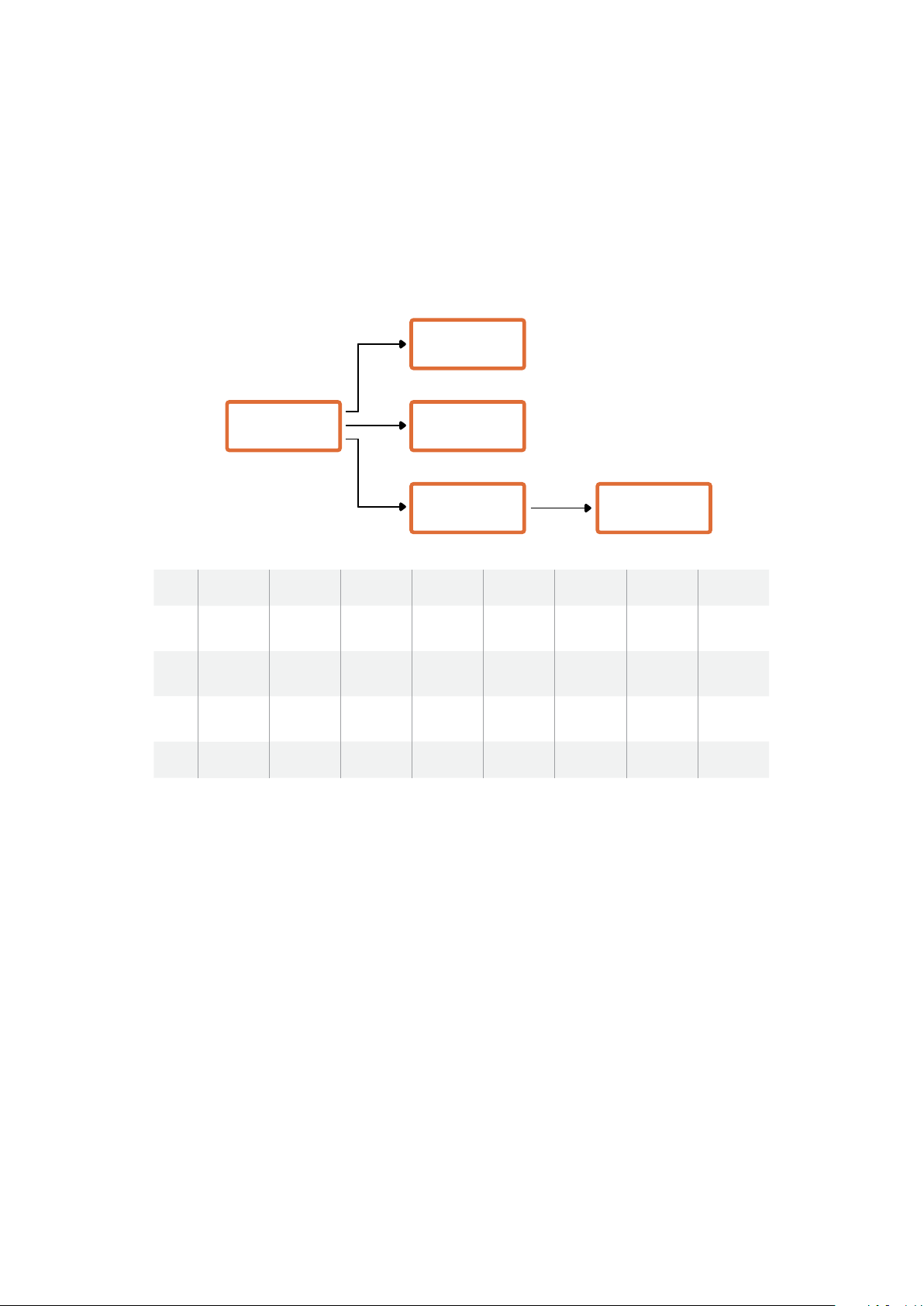
uint8[1]
bit 0: slave device 3 program tally status (0=off, 1=on)
bit 1: slave device 3 device preview tally status (0=off, 1=on)
bit 2-3: reserved (0b00)
bit 4: slave device 4 program tally status (0=off, 1=on)
bit 5: slave device 4 preview tally status (0=off, 1=on)
bit 6-7: reserved (0b00)
…
Master Device
Monitor Device
Slave Device
(2)
Slave Device
(3)
Slave Device
(1)
Byte 7 MSB 6 5 4 3 2 1 0 LSB
0
Version
(0b0)
Version
(0b0)
Version
(0b0)
Version
(0b0)
Reserved
(0b0)
Reserved
(0b0)
Monitor
Preview
Monitor
Program
1
Reserved
(0b0)
Reserved
(0b0)
Slave 1
Preview
Slave 1
Program
Reserved
(0b0)
Reserved
(0b0)
Slave 0
Preview
Slave 0
Program
2
Reserved
(0b0)
Reserved
(0b0)
Slave 3
Preview
Slave 3
Program
Reserved
(0b0)
Reserved
(0b0)
Slave 2
Preview
Slave 2
Program
3 ...
136Developer Information

Connecting Tally using the
Blackmagic3G-SDI Shield for Arduino
If you are using an SDI switcher with a tally output connector, you can connect the tally outputs
to a Blackmagic 3G-SDI shield for Arduino to send tally signals to your Blackmagic Studio
Cameras. This means you can still get tally on your Blackmagic cameras via the SDI program
return feed even if you aren’t using an ATEM switcher.
For example, the switcher’s parallel tally port connects to pins D2 - D9 of the Blackmagic shield
and the shield’s SDI output is connected to all Blackmagic cameras via a distribution amplifier,
such as a Blackmagic Mini Converter SDI Distribution. This way you can send tally to 8 separate
Blackmagic cameras.
The Blackmagic camera number must match the switcher’s tally outputs, which means you may
need to wire a custom connector to make sure the pins correspond to each camera number.
The common GND from the switcher’s tally connector must be connected to the GND pin of the
Blackmagic 3G-SDI Shield.
Below is a configuration example showing how the Blackmagic camera numbers match the
tally outputs from the switcher, which are then connected to the pins on the Blackmagic 3G-SDI
Shield for Arduino.
Blackmagic
Camera
Number
Switcher
Input
Number
Arduino
Pin
1 1 D2
2 2 D3
3 3 D4
4 4 D5
5 5 D6
6 6 D7
7 7 D8
8 8 D9
The example sketch in this section shows how the Blackmagic 3G-SDI Shield for Arduino
is programmed to send a tally signal to the camera that has been switched to the program
output. All SDI switchers that have open collector outputs are configurable for tally using the
Blackmagic 3G-SDI Shield for Arduino. Instruction manual from the Blackmagic Design support
center at
www.blackmagicdesign.com/support.
137Connecting Tally using the Blackmagic3G-SDI Shield for Arduino
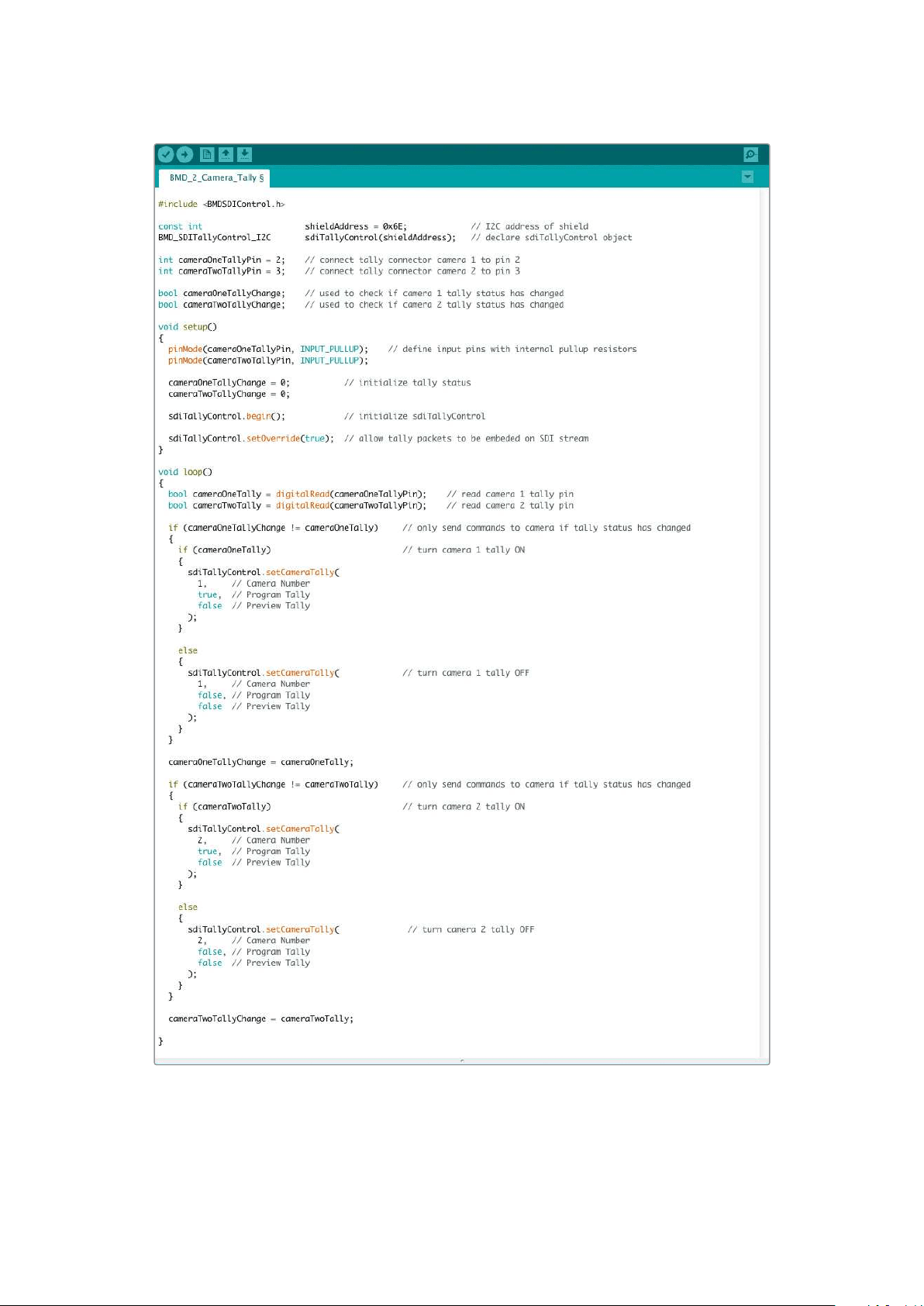
The example sketch above shows how the Blackmagic 3G-SDI Shield for Arduino is programmed
to detect a tally signal for input 1 or 2 via the switcher’s tally output, and then embed that tally signal
into the shield’s SDI output. The tally light on the corresponding camera will then illuminate.
138
Connecting Tally using the Blackmagic3G-SDI Shield for Arduino

Help
Getting Help
The fastest way to obtain help is to go to the Blackmagic Design online support pages and
check the latest support material available for your camera.
Blackmagic Design Online Support Pages
The latest manual, software and support notes can be found at the Blackmagic Design support
center at
www.blackmagicdesign.com/support.
Contacting Blackmagic Design Support
If you can’t find the help you need in our support material, please use the “Send us an email”
button on the support page for your camera to email a support request. Alternatively, click
on the “Find your local support team” button on the support page and call your nearest
Blackmagic Design support office.
Checking the Software Version Currently Installed
To check which version of Blackmagic Camera Setup software is installed on your computer,
open the About Blackmagic Camera Setup window.
On Mac OS, open Blackmagic Camera Setup from the Applications folder. Select About
Blackmagic Camera Setup from the application menu to reveal the version number.
On Windows, open Blackmagic Camera Setup from your Start menu or Start Screen.
Click on the Help menu and select About Blackmagic Camera Setup to reveal the
version number.
How to Get the Latest Software Updates
After checking the version of Blackmagic Camera Setup software installed on your computer,
please visit the Blackmagic Support Center at
www.blackmagicdesign.com/support to check
for the latest updates. While it is usually a good idea to run the latest updates, it is wise to avoid
updating any software if you are in the middle of an important project.
139Help
Regulatory Notices
Disposal of Waste of Electrical and Electronic Equipment Within the European Union.
The symbol on the product indicates that this equipment must not be disposed of with
other waste materials. In order to dispose of your waste equipment, it must be handed
over to a designated collection point for recycling. The separate collection and recycling
of your waste equipment at the time of disposal will help conserve natural resources and
ensure that it is recycled in a manner that protects human health and theenvironment.
Formore information about where you can drop off your waste equipment for recycling,
please contact your local city recycling office or the dealer from whom you purchased
the product.
This equipment has been tested and found to comply with the limits for a Class A
digitaldevice, pursuant to Part 15 of the FCC rules. These limits are designed to provide
reasonable protection against harmful interference when the equipment is operated
inacommercial environment. This equipment generates, uses, and can radiate radio
frequency energy and, if not installed and used in accordance with the instructions,
maycause harmful interference to radio communications. Operation of this product in
aresidential area is likely to cause harmful interference, in which case the user will be
required to correct the interference at personal expense.
The operation of this equipment is subject to the following two conditions:
1 This equipment or device may not cause harmful interference.
2 This equipment or device must accept any interference received, including
interference that maycause undesired operation.
R-R-BMD-20210216001
R-R-BMD-20210216002
R-R-BMD-20210729003
R-R-BMD-20220606001
R-R-BMD-20200916001
R-R-BMD-20200916002
R-R-BMD-20200415001
ISED Canada Statement
This device complies with Canadianstandards for Class A digital apparatus.
Any modifications or use of this product outside its intended use could void compliance
to these standards.
Connection to HDMI interfaces must be made with high quality shielded HDMI cables.
This equipment has been tested for compliance with the intended use in a commercial
environment. If the equipment is used in a domestic environment, it may cause radio
interference.
140Regulatory Notices

Safety Information
Blackmagic Studio Cameras
Blackmagic Studio Camera is suitable for use in tropical locations with an ambient
temperature of up to 40°C.
No operator serviceable parts inside product. Refer servicing to your local
Blackmagic Design service center.
During sunny conditions, consider shading of the camera to prevent exposure of the
camera to extended periods of sunlight.
When using the supplied power adapter, use only at altitudes not more than 2000m
above sea level.
Blackmagic Studio Converter
For protection against electric shock, the equipment must be connected to a mains
socket outlet with a protective earth connection. In case of doubt contact a qualified
electrician.
To reduce the risk of electric shock, do not expose the equipment to dripping or
splashing.
This product is suitable for use in tropical locations with an ambient temperature of
up to 40°C.
Ensure that adequate ventilation is provided around the product and that it is not
restricted.
When rack mounting, ensure that the ventilation is not restricted by adjacent equipment.
No operator serviceable parts inside product. Refer servicing to your local
Blackmagic Design service center.
Use only at altitudes not more than 2000m above sea level.
State of California statement
This product can expose you to chemicals such as trace amounts of polybrominated
biphenyls within plastic parts, which is known to the state of California to cause cancer
and birth defects or other reproductive harm.
Formore information go to www.P65Warnings.ca.gov.
141Safety Information

Warranty
12 Month Limited Warranty
Blackmagic Design warrants that this product will be free from defects in materials and workmanship
for a period of 12 months from the date of purchase. If a product proves to be defective during this
warranty period, Blackmagic Design, at its option, either will repair the defective product without
charge for parts and labor, or will provide a replacement in exchange for the defective product.
In order to obtain service under this warranty, you the Customer, must notify Blackmagic Design
of the defect before the expiration of the warranty period and make suitable arrangements for
the performance of service. The Customer shall be responsible for packaging and shipping
the defective product to a designated service center nominated by Blackmagic Design, with
shipping charges pre paid. Customer shall be responsible for paying all shipping charges,
insurance, duties, taxes, and any other charges for products returned to us for any reason.
This warranty shall not apply to any defect, failure or damage caused by improper use or improper
or inadequate maintenance and care. Blackmagic Design shall not be obligated to furnish
service under this warranty: a) to repair damage resulting from attempts by personnel other than
Blackmagic Design representatives to install, repair or service the product, b)torepair damage
resulting from improper use or connection to incompatible equipment, c)to repair any damage or
malfunction caused by the use of non Blackmagic Design parts or supplies, or d) to service a product
that has been modified or integrated with other products when the effect of such a modification or
integration increases the time or difficulty of servicing the product. THIS WARRANTY IS GIVEN BY
BLACKMAGIC DESIGN IN LIEU OF ANY OTHER WARRANTIES, EXPRESS OR IMPLIED. BLACKMAGIC
DESIGN AND ITS VENDORS DISCLAIM ANY IMPLIED WARRANTIES OF MERCHANTABILITY OR
FITNESS FOR A PARTICULAR PURPOSE. BLACKMAGIC DESIGN’S RESPONSIBILITY TO REPAIR
OR REPLACE DEFECTIVE PRODUCTS IS THE WHOLE AND EXCLUSIVE REMEDY PROVIDED TO
THE CUSTOMER FOR ANY INDIRECT, SPECIAL, INCIDENTAL OR CONSEQUENTIAL DAMAGES
IRRESPECTIVE OF WHETHER BLACKMAGIC DESIGN OR THE VENDOR HAS ADVANCE NOTICE
OF THE POSSIBILITY OF SUCH DAMAGES. BLACKMAGIC DESIGN IS NOT LIABLE FOR ANY
ILLEGAL USE OF EQUIPMENT BY CUSTOMER. BLACKMAGIC IS NOT LIABLE FOR ANY DAMAGES
RESULTING FROM USE OF THIS PRODUCT. USER OPERATES THIS PRODUCT AT OWN RISK.
© Copyright 2022 Blackmagic Design. All rights reserved. ‘Blackmagic Design’, ‘DeckLink’, ‘HDLink’, ‘Workgroup Videohub’,
‘Multibridge Pro’, ‘Multibridge Extreme’, ‘Intensity’ and ‘Leading the creative video revolution’ are registered trademarks in the
US and other countries. All other company and product names may be trade marks of their respective companies with which
they are associated.
142Warranty