Installation and Operation Manual
Blackmagic
Studio Cameras
September 2018
English,
日本語, Français, Deutsch, Español,
中文, 한국어, Русский
,
Italiano, Português and Türkçe.

Languages
To go directly to your preferred language, simply click on the hyperlinks listed in the
contents below.
English 3
日本語63
Français 124
Deutsch 185
Español 246
中文 307
한국어 368
Русский 429
Italiano 490
Português 551
Türkçe 612

Welcome
Thank you for purchasing a Blackmagic Studio Camera!
We are extremely excited to have designed the Blackmagic Studio Camera and Micro
Studio Camera 4K. Ever since I was a teenager I have loved live production, it’s so exciting!
Traditionally cameras with talkback and tally were very expensive and physically large,
so hard to manage. We really wanted to solve this problem by designing a more compact
camera that included all the talkback, tally and camera control features of physically
much larger cameras.
That’s why the Blackmagic Studio Camera was developed. We wanted to build a much
smaller camera for portability, however normally small cameras have small tiny screens.
We did not want that. What we really wanted was a much larger viewfinder! The result is
Blackmagic Studio Camera, a small broadcast camera with a very large viewfinder that’s
wonderful to use! Precise focus and framing are so easy with a viewfinder this large!
Of course you get tally indicators, talkback, of course a fantastic quality camera with
flexible MFT lens mount. It’s everything you need in a complete package! You can plug
in larger wind protected microphones even with phantom power and with user installable
optical fiber, you can add an SFP module when you need to run your camera miles away
from your switcher! If you need, you can even add a HyperDeck Shuttle and use the
camera for general production use!
Blackmagic Micro Studio Camera 4K takes the small size and capability of Blackmagic
Studio Camera even further! This tiny camera pairs an amazing Ultra HD sensor with
an incredibly tiny chassis and a host of remote control options. Now you can capture
broadcast production footage from previously impossible locations, all with complete
control from an ATEM switcher or via custom remote.
We hope you use your new camera for some amazing live productions and produce some
fantastic looking work! We are extremely excited to see what creative work you produce!
Grant Petty
CEO Blackmagic Design
English

Contents
Blackmagic Studio Cameras
Getting Started 5
Attaching a Lens 5
Turning Your Camera On 5
Connecting to a switcher 6
Camera Features 8
Blackmagic Studio Camera Features 8
Blackmagic Micro Studio
Camera 4K Features 10
Camera Connections 13
Blackmagic Studio Camera – Left Side 13
Blackmagic Studio Camera – Right Side 14
Blackmagic Micro
StudioCamera4K – Left Side 15
Blackmagic Micro
StudioCamera4K – Right Side 16
Customization 17
Blackmagic Micro Studio
Camera 4K Expansion Cable 17
Wiring diagram for the
Blackmagic MicroStudio
Camera 4K Expansion Cable 18
Settings 19
Camera Settings 19
Audio Settings 21
Monitoring Settings 22
Studio Settings 24
Remote Settings 25
Button Settings 27
Camera Video Output 29
Connecting to Video Switchers 29
Connecting to Recorders 30
Remote Record 30
RAW SDI Output 30
Connecting Tally using the
Blackmagic3G-SDI Shield for Arduino
31
Blackmagic Camera Setup 33
Attaching Accessories 34
Sun Shade 34
Other Accessories 34
Using ATEM Software Control 35
Introducing Camera Control 35
Using Camera Control 37
DaVinci Resolve Primary
ColorCorrector 41
PTZ Control over SDI 43
VISCA commands 44
PTZ with Blackmagic 3G-SDI
Shield for Arduino 45
Controlling your Arduino 46
Developer Information 48
Blackmagic SDI Camera
Control Protocol 48
Example Protocol Packets 56
Blackmagic Embedded
TallyControl Protocol 57
RAW SDI Output 58
Help 61
Warranty 62
Contents
Getting Started
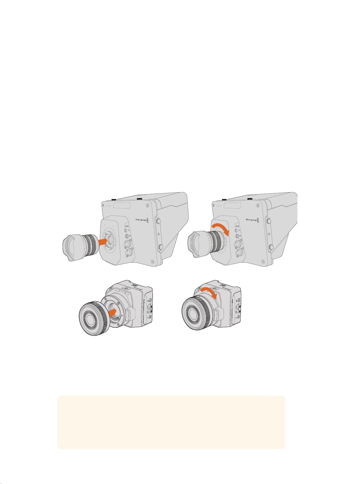
Attaching a Lens
Getting started with your Blackmagic Studio Camera or Blackmagic Micro Studio Camera 4K is as
simple as attaching a lens and turning the camera on. To remove the protective dust cap from the
lens mount, hold down the locking button and rotate the cap counterclockwise until itis released.
We recommend you always turn off your Blackmagic camera prior to attaching or removing a lens.
To attach a lens:
1 Align the dot on your lens with the dot on the camera mount. Many lenses have either
ablue, red or white dot or some other indicator.
2 Twist the lens clockwise until it locks into place.
3 To remove the lens, hold down the locking button, rotate the lens counterclockwise
until its dot or indicator reaches the 12 o’clock position and gently remove.
When no lens is attached to the camera, the lens mount is exposed to dust and other debris
soyou’ll want to keep the dust cap on whenever possible.
1
1
3
PUSH
2
2
1
3
PUSH
2
1
1
3
PUSH
2
2
1
3
PUSH
2
Attaching and removing a lens on Studio Camera.
Attaching and removing a lens on Micro Studio Camera 4K.
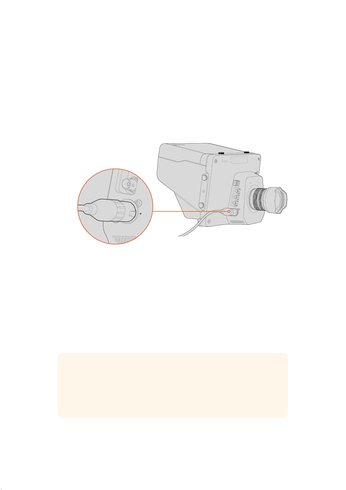
Turning Your Camera On
1
Press the power button below the LCD. On Blackmagic Studio Camera and Studio
Camera 4K models, the live camera image will appear on the LCD.
2 Press and hold the power button to switch off the camera.
TIP Blackmagic Studio Camera HD and Studio Camera 4K have internal batteries that
can be charged using the supplied power adapter. These camera can be charged and
operated while connected via external power and will switch between power sources
without interruption. Blackmagic Studio Camera 2 and Studio Camera 4K 2 does not
contain an internal battery and does not need to be charged.
5Getting Started
Micro Studio Camera 4K accepts LP-E6 and LP-E6N batteries, which can be charged with an
external battery charger or slowly trickle charged by the camera. The camera can also be
charged and operated via external power and will switch between power sources automatically
if external power is interrupted. External power is provided via the Micro Studio Camera 4K’s
expansion port.
1 Press the power button on the right hand side of the camera. The tally light will glow
white to indicate the camera is on.
2 Press and hold the power button to switch off your camera.
That’s all there is to getting started. You can now connect your camera to a switcher,
orATEMConverter, and start creating your live production!
Use the supplied power adapter to power the Studio Camera.
Connecting to a switcher
Your Blackmagic Studio Camera and Micro Studio Camera 4K can be remotely controlled from
an ATEM switcher via SDI for fast, interactive camera control during your live production.
Connecting via SDI
1 Connect your Blackmagic Studio Camera’s and Micro Studio Camera 4K’s SDI output to
any SDI input on the ATEM switcher.
2 Connect any one of the ATEM switcher’s SDI outputs, except down converted or multi
view outputs, to your Studio Camera’s SDI program input. Camera control signals are
not sent via the multi view and down converted SDI outputs.
TIP If you have the optional SFP Optical Module installed, you can use optical fiber to
connect your Blackmagic Studio Camera to an ATEM Switcher. This is great for long
cable runs as optical fiber can carry a signal up to 28 miles.
An ATEM Studio Converter or ATEM Talkback Converter 4K is required to complete the
connection to your ATEM Switcher. For more information on optical fiber setup refer to
the ‘connection diagrams’ section in the ATEM Converters manual.
OPTICAL OUT
OPTICAL IN
SDI OUT
SDI IN
REF
12V
SDI IN
REF
12V
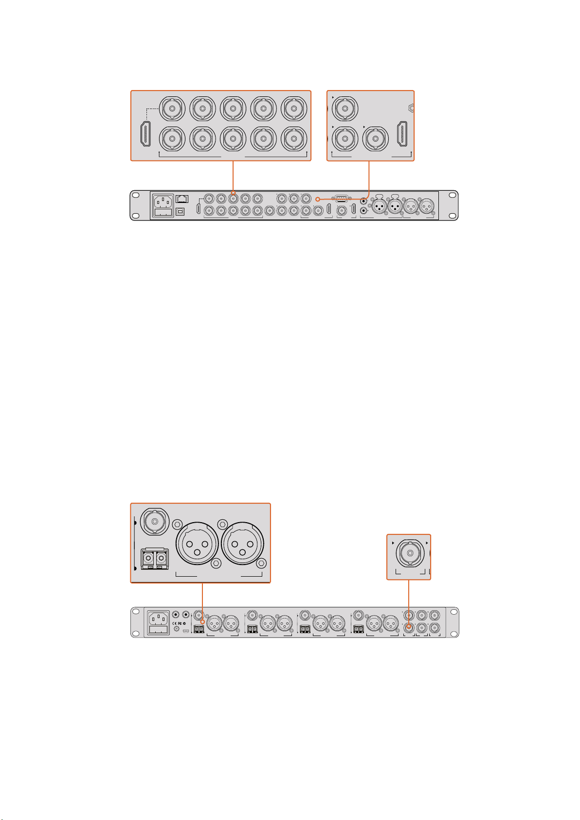
6Getting Started
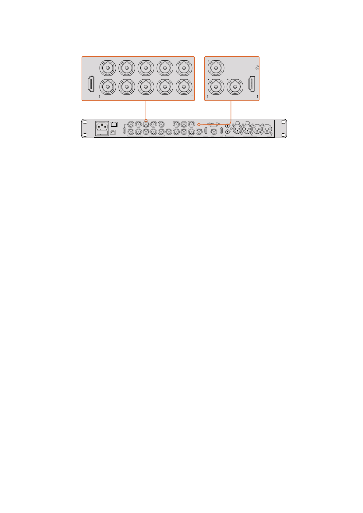
To connect your camera to an ATEM switcher, simply plug your camera’s
SDIoutput into any of your switcher’s SDI inputs. For camera control,
plug any of the ATEM switcher’s non down-converted outputs to your
camera’s programSDIinput. A quick and easy way to plug your switcher
into the camera isto connect one of the switcher’s program outputs.
Setting Button Mapping and Tally
Open ATEM Software Control Preferences and set the switcher’s button mapping settings to
make sure you are switching the right camera with correct tally.
To set the mapping settings:
1 Click on the menu bar at the top of the screen and open the ATEM Software Control
Preferences.
2 Click on the ‘Mapping’ tab and check the buttons correspond with the correct input.
Forexample, because your Studio Camera is connected to input 1 on your switcher,
‘Button 1’ should be set to ‘Input 1: Camera 1’.
3 On your Blackmagic Studio Camera, press ‘Menu’. Navigate to Studio Settings>Camera
Number and set it to match the switcher input. In this example, your Studio Camera is
connected to Cam 1 on the ATEM switcher, so the camera number must also be set to 1.
This ensures tally is sent to the correct camera.
Now that everything is plugged in and mapping is set, you can check that the program output
can be monitored on your camera and confirm that tally is working. A fast way to check is to
press the program button on your Blackmagic Studio Camera, then switch color bars to the
program output on your ATEM switcher. If you see color bars on your camera, you know the
program output is working properly with your camera.
Now switch camera 1 to the program output. The tally light on the Studio Camera should now
illuminate. If not, double check your camera number is set to the corresponding input on the
switcher, and that the mapping settings in the switcher are correct.
Using Camera Control
Your Blackmagic Studio Camera can be controlled from an ATEM switcher using the Camera
Control feature in ATEM Software Control.
Launch ATEM Software Control and click on the ‘Camera’ button located at the bottom of the
software window to open the camera control page. You will see a row of labeled camera
controllers containing tools to adjust and refine each camera’s image. Camera 1 is labelled
‘Cam 1.’ If the camera is switched to the program output it will display a red ‘On Air’ status.
Inside the ‘Cam 1’ controller you can make camera adjustments including color correction, lens
control on compatible lenses, camera settings and more. For more details on how to use the
camera control features, refer to the ‘using ATEM software control’ section for more information.
PUSH PUSH
CONTROL
USB 2.0 HDMI IN
SDI INPUTS REF IN AUX 1-3 PREVIEW PROGRAM OUTPUTS MULTI-VIEW ANALOG AUDIO IN
STEREO IN
REMOTE
ANALOG AUDIO OUT
CH 1
All SDI and HDMI video connections are
SD, HD and Ultra HD switchable unless indicated
CH 2CH 1 CH 2
IN
1
IN
2
IN
1
IN
3
IN
4
IN
5
IN
6
IN
7
IN
8
IN
9
IN
10
2
1 3
2
1
HD HD HD
PROGRAM OUTPUTS
2
1
HD
HDMI IN
SDI INPUTS
IN
1
IN
2
IN
1
IN
3
IN
4
IN
5
IN
6
IN
7
IN
8
IN
9
IN
10
7Getting Started
Connecting to a Recorder
You can also connect your Blackmagic Studio Camera to an external recorder, for example a
Blackmagic HyperDeck Studio disk recorder for indoor studio recording. Or even mount a
HyperDeck Shuttle or Blackmagic Video Assist to your studio camera and loop through to the
switcher for ISO recordings during an outside broadcast.
That’s all there is to getting started! Live production is exciting and your Blackmagic Studio
Camera is designed to give you an easy and fun experience. Please keep reading the manual
to learn about all the different features and settings on your Blackmagic Studio Camera.
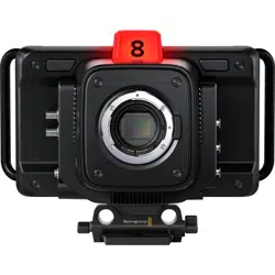
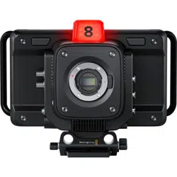
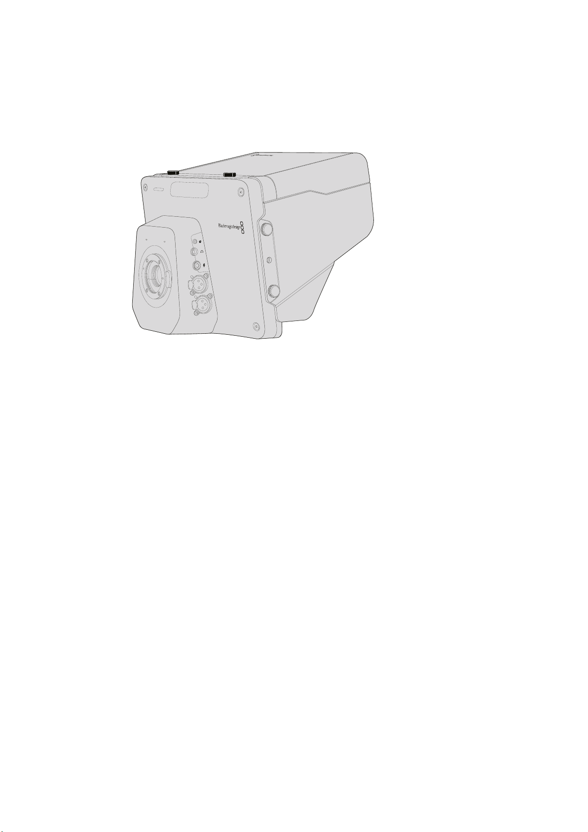
Camera Features
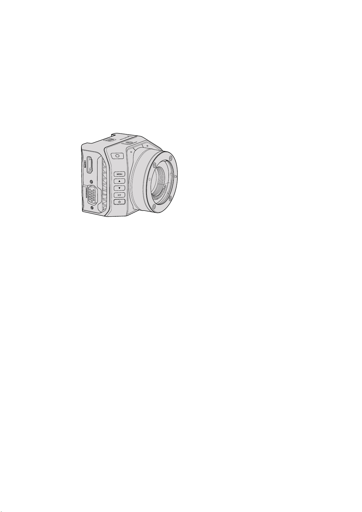
Blackmagic Studio Camera Features
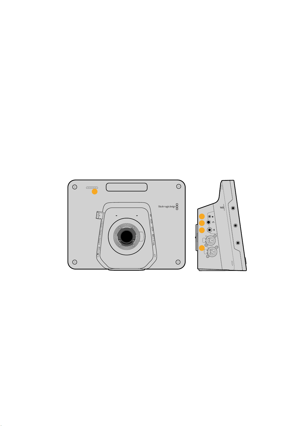
Front Panel
1 Front Tally Light
Indicates to the on-air talent which camera is currently “live”. See the
‘monitoringsettings’ section in this manual for more details.
Left Panel
2 LANC Remote
2.5mm stereo jack for LANC remote control supports iris, zoom and focus control.
3 Aviation Headphones
0.25” TRS connector for monitoring PGM and control room audio with aviation
style headsets.
4 Headphones Microphone Input
0.206” TRS connector for talking to the control room with aviation style headsets.
5 Audio Inputs
2 x 1/4” balanced XLR connectors for audio input. Refer to the ‘Blackmagic Studio
Camera - left side’ section in this manual for more details.
1
1
PUSH
2
PUSH
4
5
2
3
8Camera Features
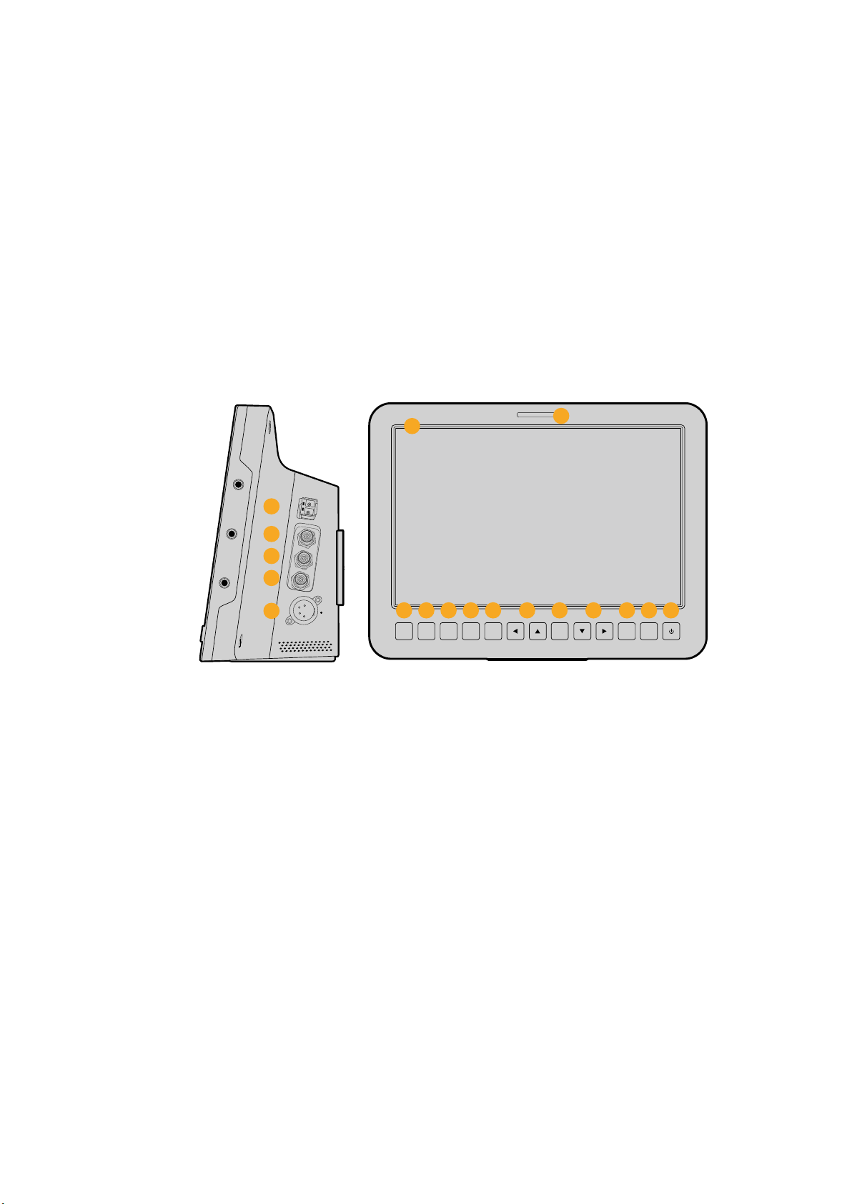
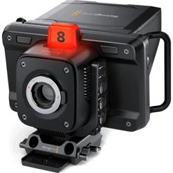
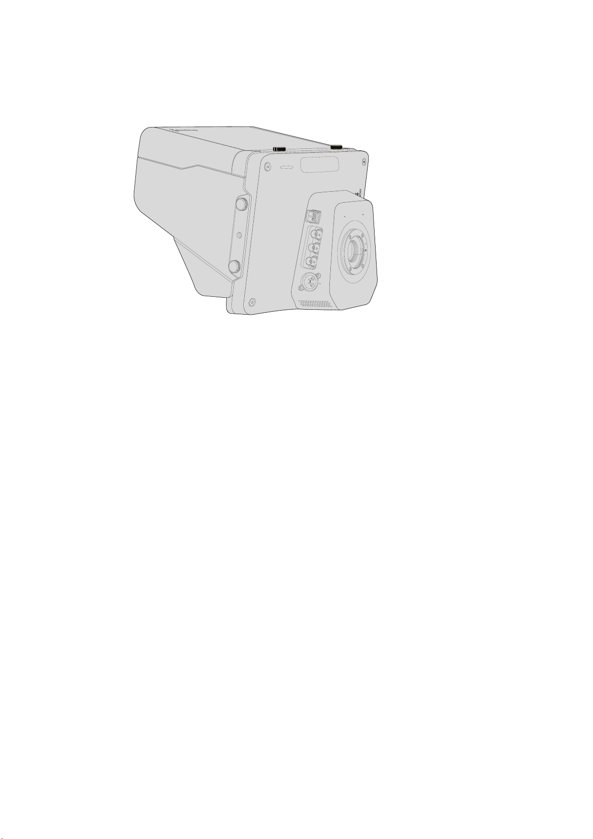
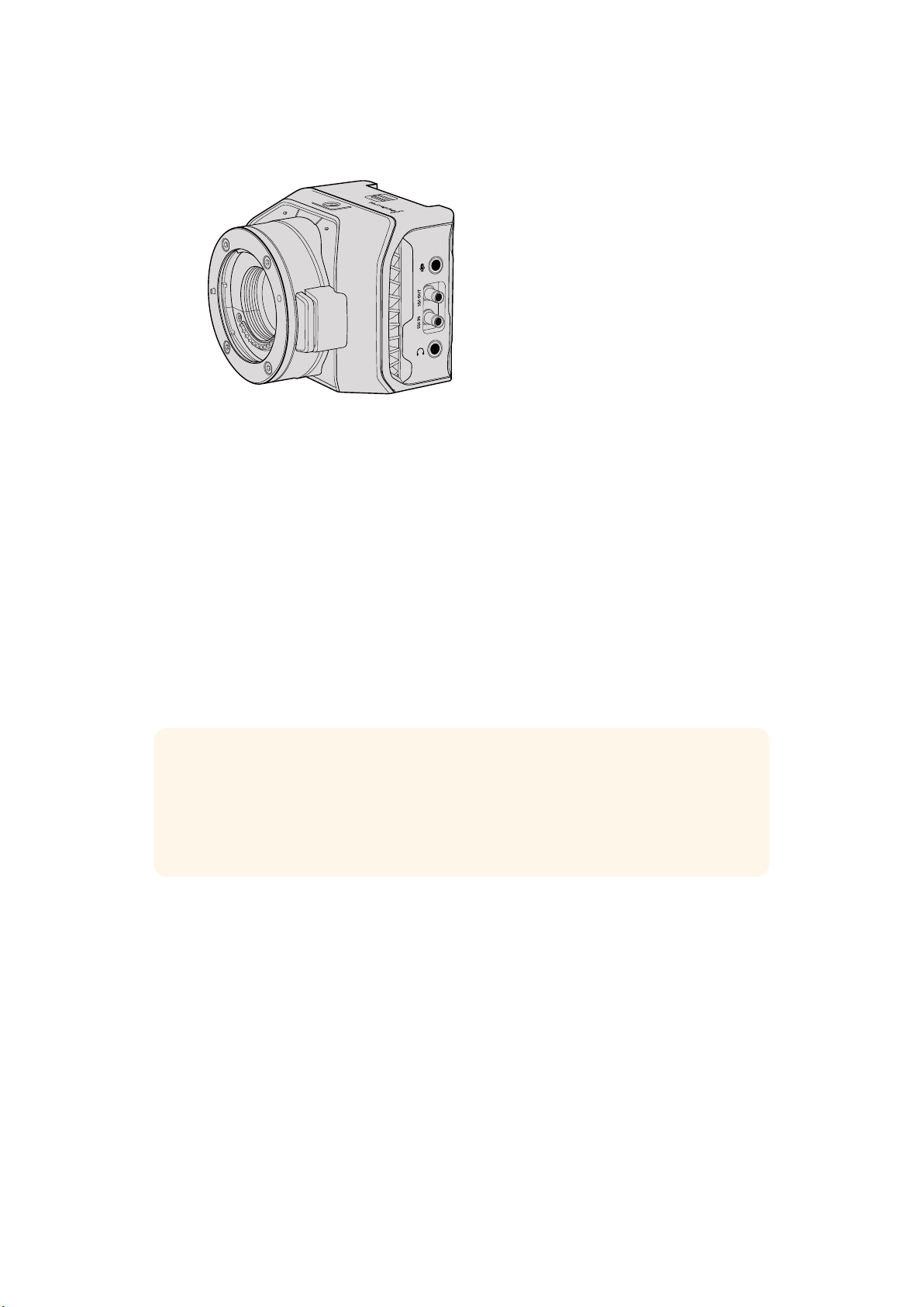
Right Panel
6 Optical Input/Output
Optical input and output allows cable runs of up to 28 miles when the optional
SFPoptical module is fitted.
7 SDI Out
SDI output for connecting to a switcher or other device.
8 SDI In
SDI input allows the camera operator to view the Program (PGM) output.
9 Reference Input
Allows multiple cameras to be genlocked to a blackburst or tri-level reference signal.
10 Power
12 – 24V power input for power supply and battery charging, where applicable. Refer to
the ‘Blackmagic Studio Camera - right side’ section in this manual for more details.
Rear Panel
11 10” LCD
Monitor live camera output or program output, or view the menu. See the ‘monitoring
settings’ in this manual for more details.
12 Rear Tally Light
When lit, it indicates to the camera operator that their camera is currently live.
13 Focus Button
Press once to auto focus or twice to display focus peaking on the LCD.
14 Iris Button
Press once for auto exposure.
15 Push To Talk Button PTT
Press and HOLD to talk. Press twice in quick succession for hands free communication.
Press again to revert to the default behavior.
16 Program PGM Button
Press to toggle between live camera output and program output from a switcher
control room.
17 Look Up Table LUT Button
Currently not implemented.
18 Menu Navigation Buttons
Navigate the menu on the LCD.
SDI OUT
OPTICAL OUT
OPTICAL IN
SDI IN
REF
12V
6
7
8
9
10
FOCUS IRIS PTT PGM LUT SET DISPLAY MENU
11
12
13 14
15
2016 21
17
221918 18
9Camera Features
19 Set Button
Use this button to confirm your menu selections.
20 Display Button
Press this button to toggle overlays on and off.
21 Menu Button
Access the menu on the LCD.
22 Power Button
Press the power button to turn on the Blackmagic Studio Camera. Press and hold the
button to turn the camera off. Refer to the ‘button settings’ section in this manual for
more details.
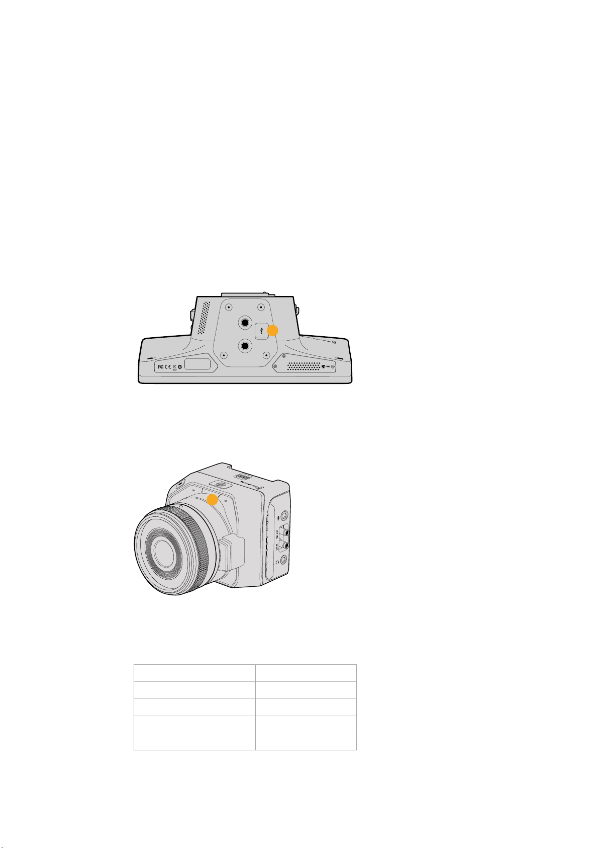
Bottom Panel
23 USB Connector
USB Mini-B port for camera firmware updates. See ‘Blackmagic Camera Setup’ section in
this manual.
Blackmagic Micro Studio Camera 4K Features
Front Panel
1 Tally Light
The Tally light indicates to on air talent which camera is currently ‘live,’ as well as
alerting the operator to the status of the camera.
The following scenarios are possible:
White Powered
Green Preview
Red Live
Alternating red and orange Battery low when live
Alternating white and orange Battery low
You can adjust the brightness of the tally light in Micro Studio Camera 4K’s settings.
See the ‘camera settings’ section for more information.
23
1
10Camera Features
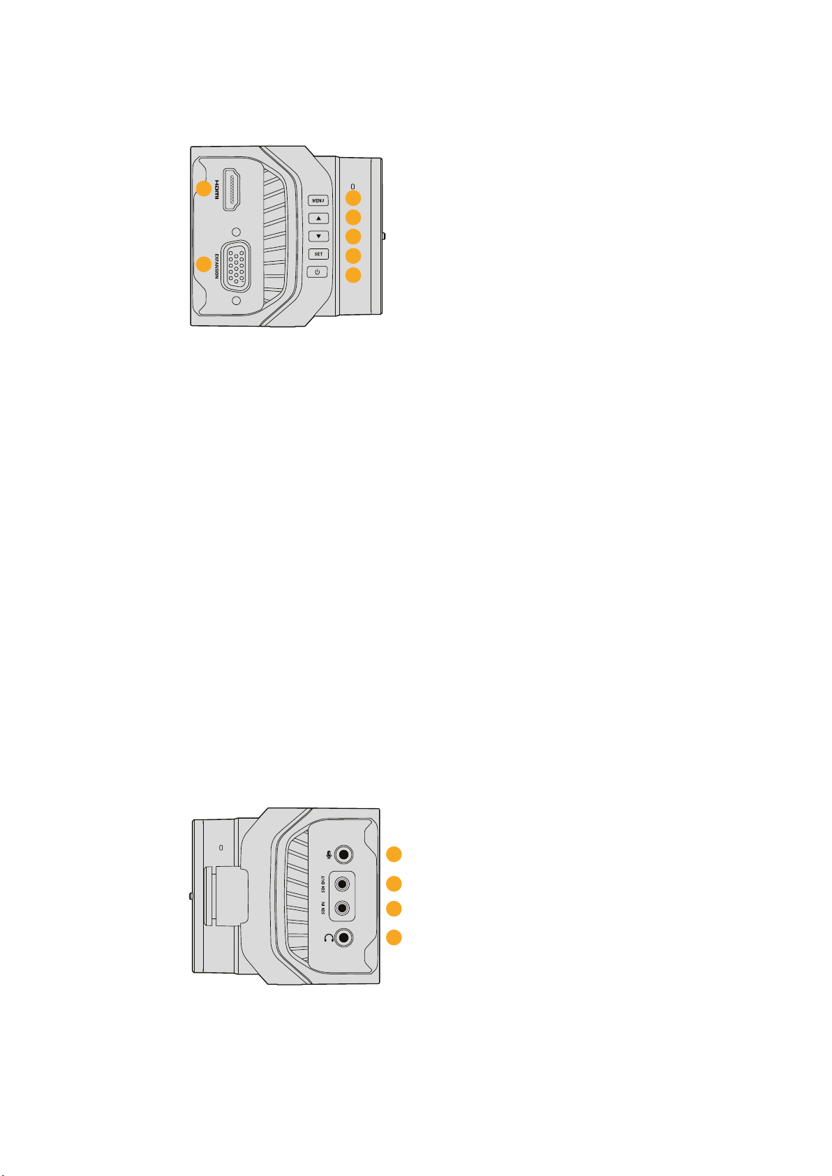
Left Panel
2 HDMI Out
The HDMI output lets you preview your video output and navigate the camera menus
using external monitors such as Blackmagic Video Assist. Output resolution is always
1080HD, unless you have 720p selected, in which case the output resolution will also
be 720p. You can choose to display overlays such as frame guides, a histogram, and
audio levels. See the ‘monitoring settings’ section in this manual for more details.
3 Expansion Port
DB-HD15 connector. Used for external power input and a range of remote control
options as well as reference input. See the section ‘Blackmagic Micro Studio Camera
4K Expansion Cable’ for details.
4 Menu Button
Use the menu buttons to access the camera’s built in menu which can be displayed on
an attached HDMI display.
5 Up Button
Use the button to navigate menus.
6 Down Button
Use this button to navigate menus.
7 Set Button
Use this button to confirm your menu selections.
8 Power Button
Press the power button to turn on the Blackmagic Micro Studio Camera 4K. Press and
hold the button to turn the camera off.
Right Panel
9 Analog Audio In
3.5mm stereo audio input, switchable between microphone and line-level input in menu.
10 SDI Out
SDI output for connecting to a switcher, external recorder or other device.
4
5
2
3
6
7
8
9
10
11
12
11Camera Features
11 SDI In
SDI input allows camera control via ATEM switchers or the Blackmagic 3G-SDI Shield
for Arduino.
12 Headphone / Talkback
3.5mm jack for talkback with iPhone and Android style headsets. Double press the
play/pause button on your headset to toggle talkback on and press it once again to turn
talkback off.
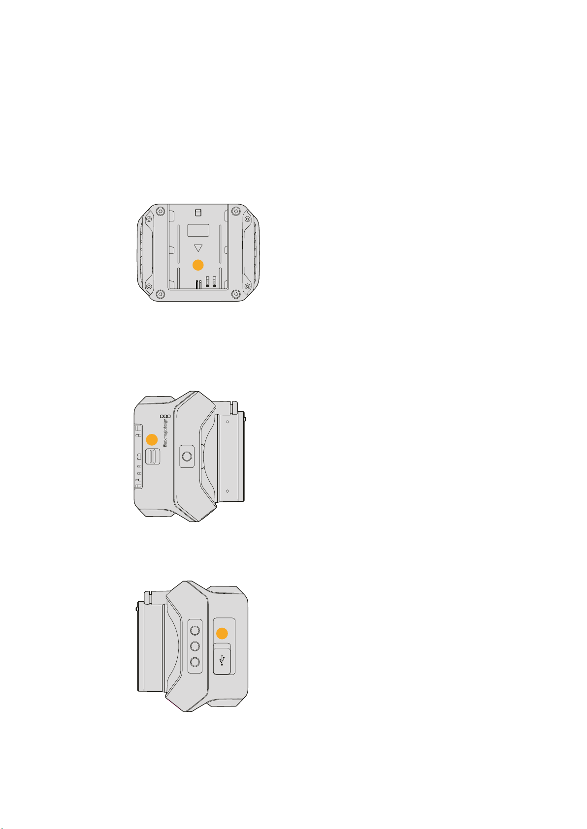
Rear Panel
13 Battery Slot
Blackmagic Micro Studio Camera 4K comes with one LP-E6 battery which fits into this
slot. The battery will be trickle charged while the camera is connected to power via its
expansion port.
Top Panel
14 Battery Release
Slide forward to release the battery.
Bottom Panel
15 USB Connector
USB port for camera firmware updates.
See the ‘Blackmagic Camera Setup’ section in this manual.
13
14
15
12Camera Features
Camera Connections
Blackmagic Studio Camera – Left Side
LANC Remote Control
The remote port on your camera is used to remotely control lens focus, iris and zoom
adjustments when using a compatible lens. The port takes a 2.5 mm stereo jack using the
standard LANC protocol.
Active MFT lenses allow you to control the zoom servo with a LANC controller. The following
lenses are currently supported:
Panasonic Lumix G X Vario PZ 14-42mm f/3.5-5.6 Power O.I.S. Lens
Panasonic Lumix G X Vario PZ 45-175mm f/4.0-5.6 Zoom O.I.S. Lens
Olympus M.Zuiko Digital ED 12-50mm f/3.5-6.3 EZ Micro 4/3 Lens
Olympus M.Zuiko Digital ED 14-42mm f/3.5-5.6 EZ Micro 4/3 Lens
Headphones Output
For monitoring program and control room audio with aviation style headsets with “fixed wing”
connectors. Aviation headsets range from single ear models for use in studio environments to
full size noise cancelling models which are suitable for loud concerts or sporting events. Audio
is taken from channel 15 and 16 of the incoming SDI signal. Channels 15 and 16 are rarely if ever
used during production and so are very suitable to serve for the audio talkback.
Headphones Microphone Input
For talking to the control room with aviation style headsets. Audio is embedded into channel
15and 16 of the SDI signal output.
Audio Inputs
Two channels of professional balanced analog audio is supported via XLR connectors. Use the
audio menu to set the input levels for each channel. The inputs support both mic level inputs
and line level inputs and the input type is also selected from the audio menu. Audio is
embedded into channel 1 and 2 of the SDI stream.
1
1
3
PUSH
2
2
1
3
PUSH
2
13Camera Connections
Blackmagic Studio Camera – Right Side
Optical Input/Output
For optical fiber input and output, you will need to install an optional optical fiber SFP module.
This lets you connect industry standard LC connectors, supporting 3G-SDI on Studio Camera
HD, and 6G-SDI on Studio Camera 4K. Optical fiber cable is widely available because it’s the
same cable used in computer networking. Optical fiber allows cable runs of up to 28 miles
which is more than enough for even the most demanding outside broadcast event.
If both optical and SDI inputs are connected, the output from the device which was connected
first will be used. To purchase an optical fiber SFP module for your Blackmagic Studio Camera,
contact your nearest Blackmagic Design reseller. You can find your nearest reseller on our
website at www.blackmagicdesign.com/resellers.
SDI Out
Use the SDI Out connector to output 10-bit 4:2:2 video to professional SDI video equipment
such as routers, monitors, SDI capture devices and broadcast switchers. Blackmagic Studio
Camera HD supports 3G-SDI, and Studio Camera 4K supports 12G-SDI.
SDI In
The SDI input allows the camera operator to view the Program (PGM) output. Simply press the
PGM button to toggle between live camera output and Program output from a switcher
control room.
If both optical and SDI inputs are connected, the output from the device which was connected
first will be used. If you’re using the Studio Camera to record to a device such as the
Blackmagic Hyperdeck Shuttle, the output from the Hyperdeck can be connected to the SDI
input so you can playback what you have just recorded.
Reference Input
This allows multiple cameras to be genlocked to a blackburst or tri-level reference signal.
Genlocking cameras to an external reference signal helps to prevent timing errors which may
result in the picture jumping when switching between different cameras.
OPTICAL OUT
OPTICAL IN
SDI OUT
SDI IN
REF
12V
14Camera Connections
Power
Use the 12 - 24V power input for connecting your power supply and to charge the internal
battery in Blackmagic Studio Camera HD and Blackmagic Studio Camera 4K. When the battery
in these cameras is charged it will power the camera for up to 4 hours on Studio Camera HD,
and up to 3 hours on Studio Camera 4K.
Blackmagic Studio Camera 2 and Studio Camera 4K 2 do not have internal batteries.
Blackmagic Micro StudioCamera4K – Left Side
HDMI Output
The HDMI port on your Blackmagic Micro Studio Camera 4K outputs 10-bit 4:2:2 1080p video
with 2 channels of audio for monitoring purposes. You can connect any HD capable HDMI
monitor, such as Blackmagic Video Assist, to frame and focus shots as well as navigating the
Micro Studio Camera 4K’s menus.
The frame rate of the HDMI output will match the format of the camera. For example, if the
camera is set to 2160p30, the HDMI output will be 1080p30.
When connected to an ATEM switcher, Blackmagic Micro Studio Camera 4K provides a two
stage tally indicator on a monitor connected via the camera’s HDMI output. The monitor
displays a green border when switched to the preview output of the switcher, and red when
switched to the program output.
Expansion Port
Blackmagic Micro Studio Camera 4K’s small size makes it easy to capture unique shots from
close to the action or difficult to reach spots. While your Micro Studio Camera 4K can be easily
tucked away out of sight, the same can’t always be said of a camera operator. So being able to
remotely control your camera is important to making full use of its tiny size.
You can adjust some settings on Micro Studio Camera 4K via SDI input with an ATEM Switcher,
as detailed in the section ‘Introducing Camera Control’ in this manual. However, the majority of
control options are provided by the expansion port.
Blackmagic Micro Studio Camera 4K’s DB-HD15 connector provides a wide range of connections,
including power, LANC remote, pan, tilt, zoom and genlock via the expansion cable included.
We encourage you to use a wide range of easily available cables to access specific features, or to
solder your own custom connections and adapt the Micro Studio Camera 4K to your needs. See the
‘Blackmagic Micro Studio Camera 4K Expansion Cable’ section in this manual for more information.
15Camera Connections
Blackmagic Micro StudioCamera4K – Right Side
Analog Audio In
The 3.5mm stereo audio connector accepts microphone or line level audio. You can switch
between these options in the camera’s ‘audio settings’ menu. It’s important to select the
appropriate setting or your audio may sound too quiet or too loud.
SDI Out
Use the SDI out connector to output 10-bit 4:2:2 video to professional SDI video equipment
such as routers, monitors, SDI capture devices and broadcast switchers. Blackmagic Micro
Studio Camera 4K supports 6G-SDI. You will need a DIN 1.0/2.3 to BNC adapter cable to
connect to devices with full size BNC connectors.
SDI In
Use the SDI in connector to control your Micro Studio Camera 4K via ATEM switchers. Refer to
the section ‘Introducing Camera Control’ for information about which controls are available.
TIP You can also control your Micro Studio Camera via a Blackmagic3G-SDI Shield for
Arduino. The shield embeds the same Blackmagic control data packets in the SDI
signal as you would get with an ATEM switcher. This means by connecting the program
return feed from any SDI switcher, through the shield to the SDI input on your camera,
you can access all the same Blackmagic camera controls you get with ATEM switchers.
Headphone / Talkback audio
The 3.5mm headphone / talkback input lets you talk to the control room with iPhone or Android
style headsets. Double press the play/pause button on your headset to enable talkback, and
press once to disable. Audio is embedded into channel 15 and 16 of the SDI signal output.
16Camera Connections
Customization
Blackmagic Micro Studio Camera 4K Expansion Cable
There are two ways to access the expansion port’s functions. You can use the expansion cable
that comes with your Micro Studio Camera 4K, or solder your own custom connectors.
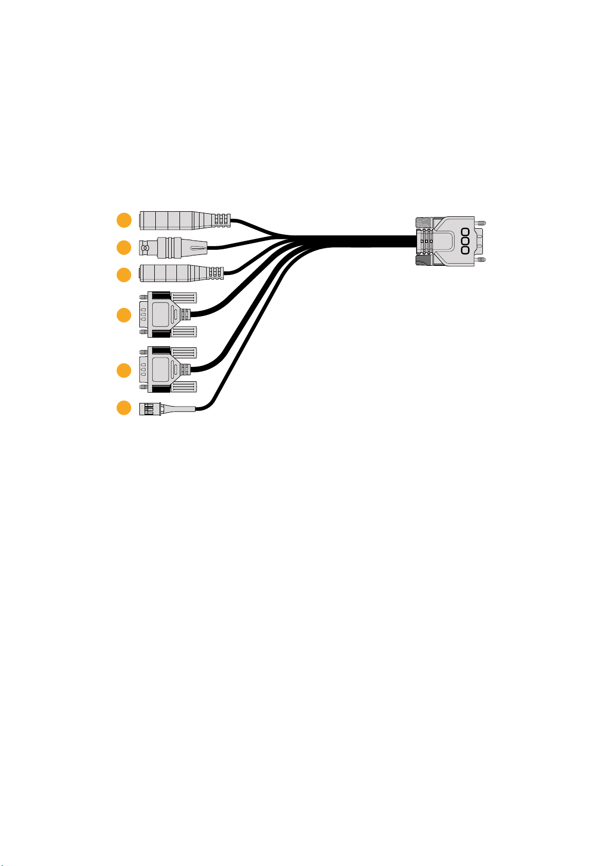
The expansion cable provides connectors for the following control options.
Blackmagic Micro Studio Camera 4K expansion cable.
1 Power Input
The 12V power input connects via a DC jack and provides power to the Micro Studio
Camera 4K, as well as trickle charging any batteries attached. When mains power is
supplied, the camera will automatically turn on.
2 Reference Input
This allows multiple cameras to be genlocked to a blackburst or tri-level reference
signal. Genlocking cameras to an external reference signal helps to prevent timing errors
which may result in the picture jumping when switching between different cameras.
3 LANC
Connect wired LANC remote controllers to the 2.5mm jack for controlling functions like
zoom, iris adjustment, and focus from a tripod arm when using compatible lenses.
4 Pan Tilt Zoom
The RS-422 connector is used to relay pan tilt zoom commands received by
MicroStudio Camera 4K from its SDI input to a motorized head.
Refer to the ‘PTZ Control over SDI’ section for more information about PTZ control.
5 B4 Communication
The DB-9 connector allows you to power and control B4 broadcast lenses attached to
the Micro Studio Camera 4K via an MFT to B4 adapter. To control a compatible B4 lens,
simply connect the optional Digital B4 Control Adapter cable to the cable from the lens,
then connect the other end to the DB-9 serial connector on your expansion cable.
4
5
2
3
6
1
17Customization
You can adjust settings such as iris, focus and zoom in the same way you would an
active MFT lens, either via an ATEM switcher using the ‘camera control’ page, or via
other remote control interfaces that can be connected to the Micro Studio Camera 4K
expansion cable. For a list of supported B4 digital lenses, refer to the
Blackmagic Design support center at www.blackmagicdesign.com/support/faq/59011
6 S.Bus Digital Servo
By connecting to a compatible S.Bus receiver using the Futaba J cable, you have
17S.Bus remote channels where features of the camera can be assigned to and
remotely controlled. Channel 18 is reserved as a reset switch so that the camera can be
reset to its default exposure settings. These features can include focus, servo zoom, iris
control and other such features. For more information about mapping functions to S.Bus
remote channels, see the ‘Remote Settings’ section of this manual.
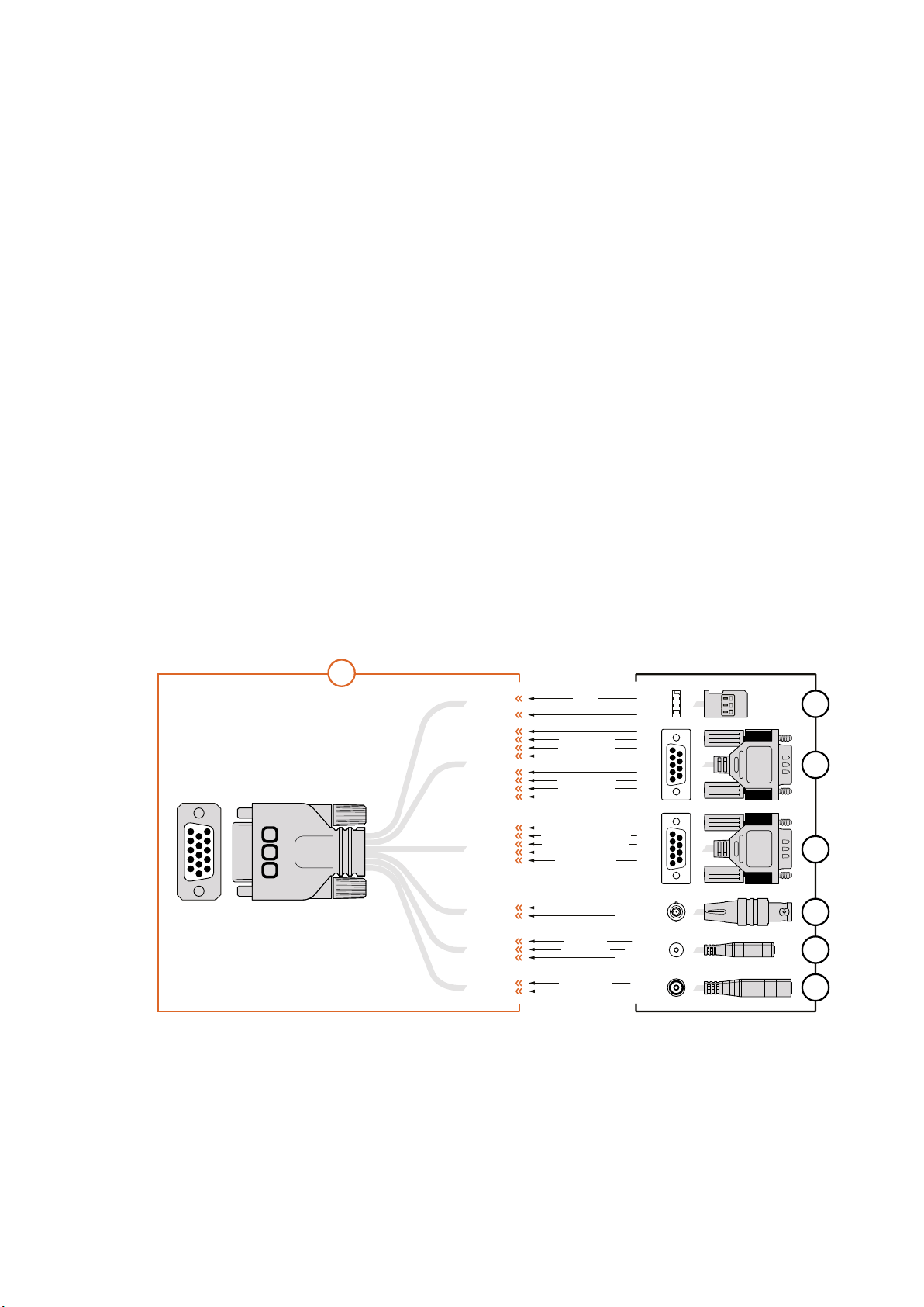
Wiring diagram for the Blackmagic
MicroStudio Camera 4K Expansion Cable
When using Blackmagic Micro Studio Camera 4K’s expansion port you may only want to access
one or two functions. For example, you may want to control an attached B4 Broadcast Lens
while simultaneously receiving 12V power and a reference signal. It’s easy to make a connector
that will give you just these functions without the clutter of additional, unused connectors.
Use the following diagram when wiring the expansion cable included or use it as an example for
how you can wire up the connections on your own custom cable correctly. The full range of
available pins are listed under group P1, while the subsets used for particular functions, as well as
their layout within the appropriate connectors, are shown in groups P2 through P7.
PIN ASSIGNMENT
1
2
3
1
2
3
4
5
6
7
8
9
1
2
3
4
5
OTHER
CENTER
SLEEVE
PIN
SLEEVE
2
GROUND
GROUND
12
8
GROUND
GROUND
13
3
GROUND
GROUND
14
15
GROUND
6
5
GROUND
6
GROUND
9
10
GROUND
TIP
RING
SLEEVE
1
2
3
4
5
6
7
8
9
1
2
3
4
5
6
7
8
9
P2
P3
P4
P5
P6
P7
P1
1 Ground
2 S. Bus
3 PTZ RS422 Tx-
4 Ground
5 Reference Input
* Power input to the camera is also used to power the lens. Beware of applying excessive voltages if you’re using
your own power supply to avoid damage to the lens.
6 Power +12V in
7 Ground
8 PTZ RS422 Tx+
9 LANC Data
10 LANC Power
11 Ground
12 PTZ RS422 Rx-
13 PTZ RS422 Rx+
14 B4 Lens Control Transmit
15 B4 Lens Control Receive
S. Bus
PTZ RS422 Rx-
PTZ RS422 Tx+
PTZ RS422 Rx+
PTZ RS422 Tx-
B4 Lens Control Transmit
B4 Lens Control Receive
Power +12V in*
Reference Input
LANC Data
LANC Power
Power +12V in
1
2
3
4
5
11
12
13
14
15
6
7
8
9
10
18Customization
Settings
You can change settings on your Blackmagic camera to get the best picture, such as video
format, shutter speed and white balance, plus you can adjust audio levels, monitoring settings,
and studio tally and talkback settings for effective communication with the control room.
This section of the manual contains detailed information on each of the settings in your camera.
Camera Settings
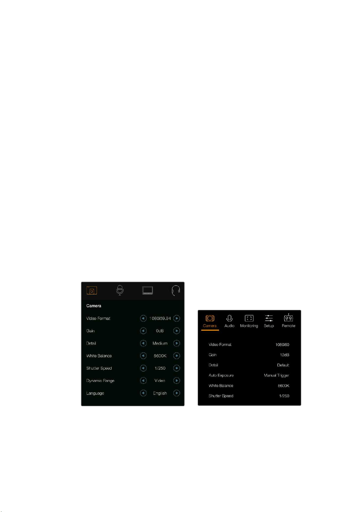
To configure the camera settings on your Blackmagic Studio Camera or Blackmagic Micro
Studio Camera 4K, press the ‘menu’ button. Use the menu navigation buttons to highlight items
and press the ‘set’ button to confirm your selection.
If you are using the Micro Studio Camera 4K, you will need to connect an external monitor via
the camera’s HDMI port to view menu settings.
Video Format
Select your desired video format using the navigation buttons. For example, to select between
1080p and 1080i formats, press the left or right arrow buttons to progress through the format
options. Press the ‘set’ button to confirm the format you want.
A list of supported video formats is provided later in this section.
Gain
Gain settings are helpful when you are shooting in low light conditions. The default setting on
Blackmagic Studio Camera is 0dB and gain can be increased in 6dB increments up to 18dB.
Gain settings on Blackmagic Micro Studio Camera 4K range from -12dB to +12dB and can be
increased in 6dB increments. The 0dB setting is the default setting with no gain added to
the picture.
Camera settings – Blackmagic Studio Camera Blackmagic Micro Studio Camera 4K
Detail
Use this setting to sharpen your image live from your Studio Camera. Decrease or increase the
level of sharpening by selecting ‘off’ or ‘default’ for low sharpening, ‘medium’ and ‘high’.
19Settings

Auto Exposure
Blackmagic Micro Studio Camera 4K gives you several auto exposure options.
Iris
Maintains a constant shutter speed while changing the aperture to achieve a
constantexposure.
Shutter
Maintains a constant aperture while changing the shutter speed to achieve a
constantexposure.
Iris + Shutter
Mantains the correct exposure levels by adjusting the aperture. If the maximum or
minimum available aperture is reached and exposure still cannot be maintained,
MicroStudio Camera 4K will begin adjusting the shutter speed to keep
exposureconstant.
Shutter + Iris
Maintains the correct exposure levels by adjusting the shutter speed. If the maximum or
minimum available shutter speed is reached and exposure still cannot be maintained,
MicroStudio Camera 4K will begin adjusting the aperture to keep exposure constant.
Manual Trigger
Iris aperture and shutter speed are set manually and exposure may vary with changing
light conditions.
White Balance
Eighteen white balance presets are selectable for a variety of color temperature conditions.
2500, 2800, 3000, 3200, 3400, 3600, 4000, 4500 and 4800K for various conditions
under tungsten, incandescent or fluorescent light, or under dull natural light including
candle light, sunrise/sunset, morning, and after noon light.
5000, 5200, 5400 and 5600K for outdoors on a clear, sunny day.
6000, 6500, 7000, 7500 and 8000K for a variety of daylight conditions.
Shutter Speed
Shutter speed complements the gain setting by regulating the amount of light on the sensor.
There are 15 different shutter speeds available ranging from 1/50 sec to 1/2000 sec.
Blackmagic Studio Cameras Supported Video Formats
Blackmagic
Studio Camera
Blackmagic
Studio Camera 4K
Blackmagic Micro
Studio Camera 4K
720p50 720p50 720p50
720p59.94 720p59.94 720p59.94
720p60 720p60 720p60
1080i50 1080i50 1080i50
1080i59.94 1080i59.94 1080i59.94
1080i60 1080i60 1080i60
1080p23.98 1080p23.98 1080p23.98
1080p24 1080p24 1080p24
1080p25 1080p25 1080p25
1080p29.97 1080p29.97 1080p29.97
20Settings
Blackmagic
Studio Camera
Blackmagic
Studio Camera 4K
Blackmagic Micro
Studio Camera 4K
1080p30 1080p30 1080p30
1080p50 1080p50 1080p50
1080p59.94 1080p59.94 1080p59.94
1080p60 1080p60 1080p60
– 2160p23.98 2160p23.98
– 2160p24 2160p24
– 2160p25 2160p25
– 2160p29.97 2160p29.97
– 2160p30 2160p30
– 2160p50 –
– 2160p59.94 –
– 2160p60 –
Audio Settings
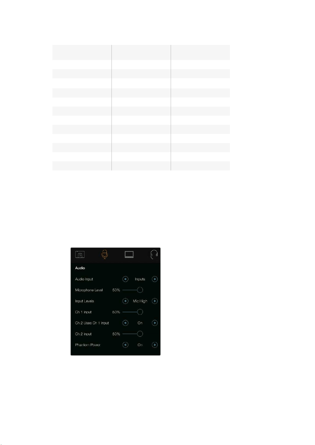
To adjust audio input and audio monitoring settings on your Blackmagic Studio Camera,
pressthe ‘menu’ button and select the microphone icon to the left of the display. Use the
menunavigation buttons to highlight menus and use the ‘set’ button to confirm your selection.
Automatic Gain Control
Blackmagic Micro Studio Camera 4K features an automatic audio gain control setting that lets
camera adjust the audio recording levels. It automatically reduces the audio gain levels if the
input level gets too loud and subtly raises it if it is too low.
Audio settings – Blackmagic Studio Camera.
Audio Input
Switches audio between using the camera’s internal microphone and the XLR audio connectors.
21Settings

Microphone Level
Microphone input adjusts the recording levels of the built in microphone. Move the audio
sliderleft or right to increase or decrease levels. Studio Camera has a built in stereo
microphone. The built in microphone records to audio channels 1 and 2 when no external audio
source isconnected.
Input Level
External audio connectors support audio at microphone level or line level. Select Line when
connecting external audioequipmentsuch as an audio mixer or amplifier.Select the mic low or
mic high setting depending on the signal strength of your microphone. It’s important to select
the appropriate level to avoid your external audio sounding almost inaudible or too hot and
distorted. Set the external audio input levels by using the left and right arrows.
Ch 1 Input
Move the audio slider icon left or right to increase or decrease levels for channel 1. The external
audio input overrides the built in microphone and is output to audio channel 1.
Ch 2 Uses Ch 1 Input
Select ‘on’ if you want to embed channel 1 external audio into channels 1 and 2 of the SDI or the
optional optical fiber output. This is the same as connecting input 1 to both audio channels in
the camera and is useful when using microphones with a single mini audio output and you need
to connect both stereo audio channels to it. Select this setting to off if you want channel 1 audio
to remain on one channel only and channel 2 will take audio from the channel 2 audio input,
which is preferred when using stereo audio sources.
Ch 2 Input
Move the audio slider icon left or right to increase or decrease levels for channel 2.
Theexternal audio input overrides the built in microphone and is output to audio channel 2.
Phantom Power
Phantom power supplies power through microphone cables and is a convenient power source for
condenser microphones. Enable or disable phantom power for studio cameras with XLR inputs by
navigating to the ‘audio’ menu and selecting on or off using the arrow buttons. Phantom power is
automatically disabled when the ‘line input level’ setting is selected. Be sure to wait at least 10
seconds for phantom power to discharge after disconnecting before plugging in a self powered
microphone. Older ribbon type microphones are not suitable for phantom power usage.
Monitoring Settings
To adjust the display settings for the LCD, press the ‘menu’ button and select the monitor icon.
Use the menu navigation buttons to highlight menus and use the ‘set’ button to confirm
yourselection.
HDMI Meters
Blackmagic Micro Studio Camera 4K gives you the option to select which meters you want to
display on the HDMI output.
Histogram
The histogram shows the contrast between whites and blacks along a horizontal scale.
The left edge of the histogram displays shadows, or blacks, and the far right displays highlights,
or whites. When you close or open the lens aperture, you’ll notice the information in the
histogram moves to the left or right accordingly.
22Settings
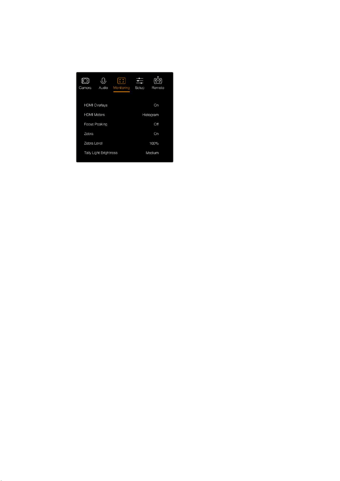
This setting toggles the histogram on and off. When on, this will appear in the bottom right
corner of an attached monitor when ‘HDMI overlays’ are set to on.
Monitoring settings - Blackmagic Micro Studio Camera 4K.
Audio
The audio meter represents the current volume of left and right audio channels in two horizontal
bars. Left is on top, right is on the bottom. If your audio levels rise too high, your audio peaks
can be clipped and you will hear distortion in your audio. To avoid this, adjust the audio gain on
your camera until your audio levels stay within safe levels.
This setting toggles the audio meter on and off. When on, this will appear in the bottom left
corner of an attached monitor when ‘HDMI overlay’ are set to on.
HDMI Overlays
This setting is only available on Micro Studio Camera 4K. When set to ‘on,’ HDMI video output
will include frame guides and information about the camera settings and identity, as well
as any meters enabled via the ‘HDMI meters’ setting.
Brightness
Move the slider icon left or right to adjust brightness settings for the LCD.
Thedefaultsetting is 60%.
Zebra
Blackmagic Cameras have a zebra feature which gives an indication of exposure levels.
Diagonal lines will appear across any part of the video that exceeds the zebra exposure level.
Turn zebra on and select the desired zebra warning level by using the left and right arrows.
Thedefault setting is medium.
Focus Peaking
Allows you to change the level of focus peaking. The settings include: off, low, medium and
high. Adjust this setting when you are using a very sharp lens and the peaking covers the entire
image. The default setting is medium.
Front Tally Brightness
Changes the brightness of the front tally light. Settings include: off, low, medium and high.
Thedefault setting is medium.
23Settings
Rear Tally Brightness
Changes the brightness of the rear tally light. Settings include: low, medium and high.
Thedefault setting is medium.
Tally Light Brightness
Changes the brightness of the tally light on Micro Studio Camera 4K. The default setting is
medium but you can also set it to high, low or off.
If you have set the tally brightness to ‘off’, the tally light will illuminate when your camera is
powered on, and then will turn off shortly afterwards.
Display Battery Percentage
Some LP-E6 batteries can tell the camera their charge levels directly via digital serial
communication. If this option is enabled, you can display the battery levels for Micro Studio
Camera 4K using a percentage value instead of graphical bars. However, if you find the
percentage display inaccurate, you can switch back to using graphical bars which measures
of the state of charge directly off the battery.
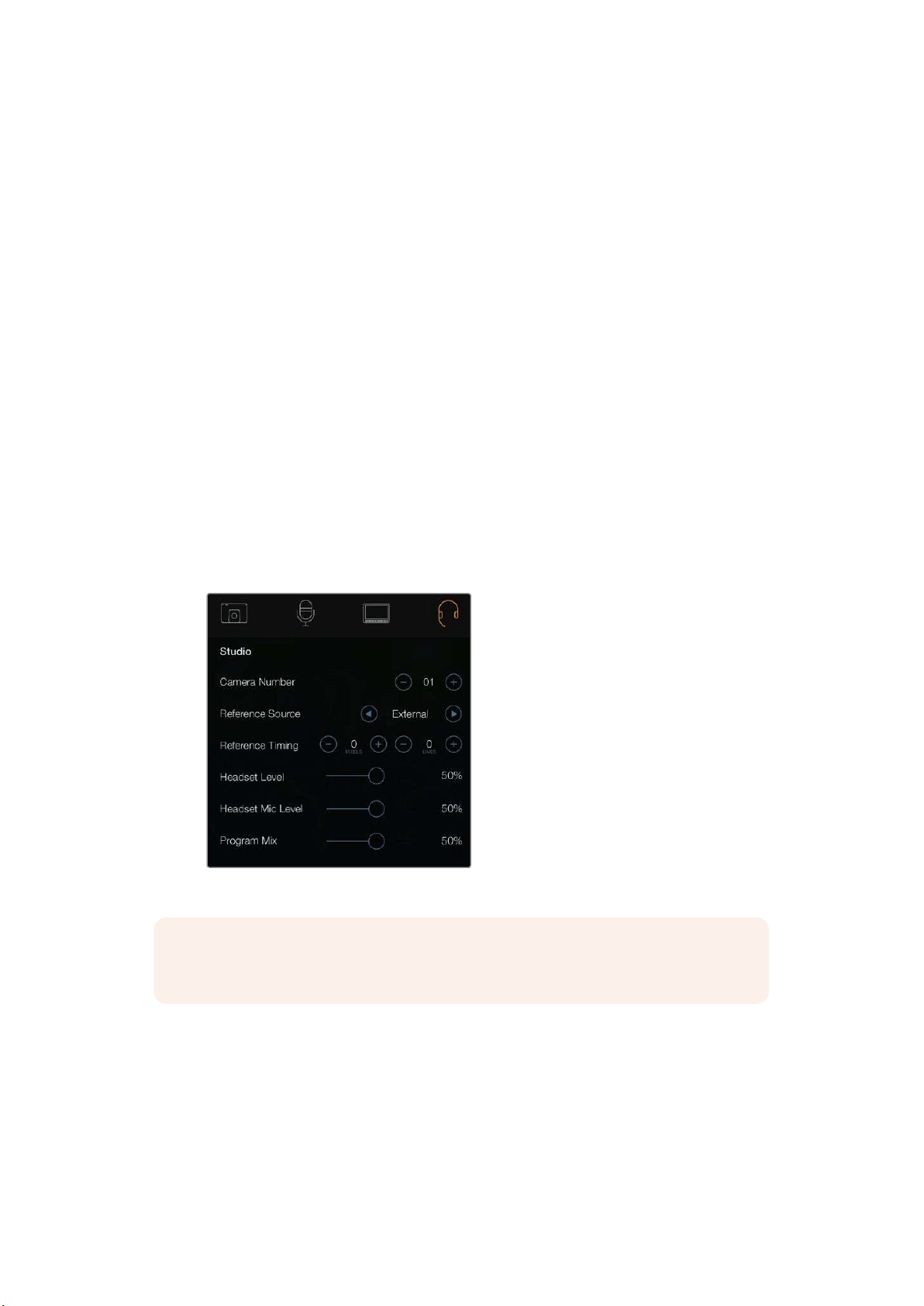
Studio Settings
To adjust the display settings for the LCD, press the ‘menu’ button and select the headphones
icon. Use the menu navigation buttons to highlight menus and use the ‘set’ button to confirm
your selection.
Studio settings – Blackmagic Studio Camera.
NOTE Blackmagic Micro Studio Camera 4K provides these settings in the menu titled
‘Setup’.
Camera Number
If you want your Studio Camera to receive tally signals from an ATEM switcher, you’ll need to set
the camera number on your camera. This ensures the switcher sends the tally signal to the
correct camera. The camera number can be set to a value of 1-99. The default setting is 1.
24Settings
TIP You can also connect the program return feed from any SDI switcher to your
camera via a Blackmagic 3G-SDI Shield for Arduino and display tally on each camera.
AllSDI switchers that have open collector tally outputs are configurable for tally using
the Blackmagic 3G-SDI Shield for Arduino. Refer to the section titled ‘Connecting tally
using the Blackmagic 3G-SDI Shield for Arduino’ for more information.
Reference Source
Used to select the genlock source. The Studio Camera can lock to program SDI input or
external genlock source. If using an external genlock source, be aware that changing that
source will most likely cause a glitch as the camera locks to the new source.
On Blackmagic Micro Studio Camera 4K, the HDMI overlays will display ‘REF’ on screen when
a valid reference source is detected and the camera is locked to it.
Reference Timing
Allows you to manually adjust the reference timing on a line or pixel basis.
Headset Level
Move the volume slider left or right to increase or decrease audio monitoring levels.
The default setting is 50%.
Headset Mic Level
Move the volume slider left or right to increase or decrease audio microphone input levels.
Thedefault setting is 50%.
Program Mix
Changes the balance of camera sound to talkback sound. The headphones will output audio
following what is displayed on the LCD. For instance, if you are in camera view, camera audio
is heard. And if you are in program view, program audio is heard. The default setting is 0%.
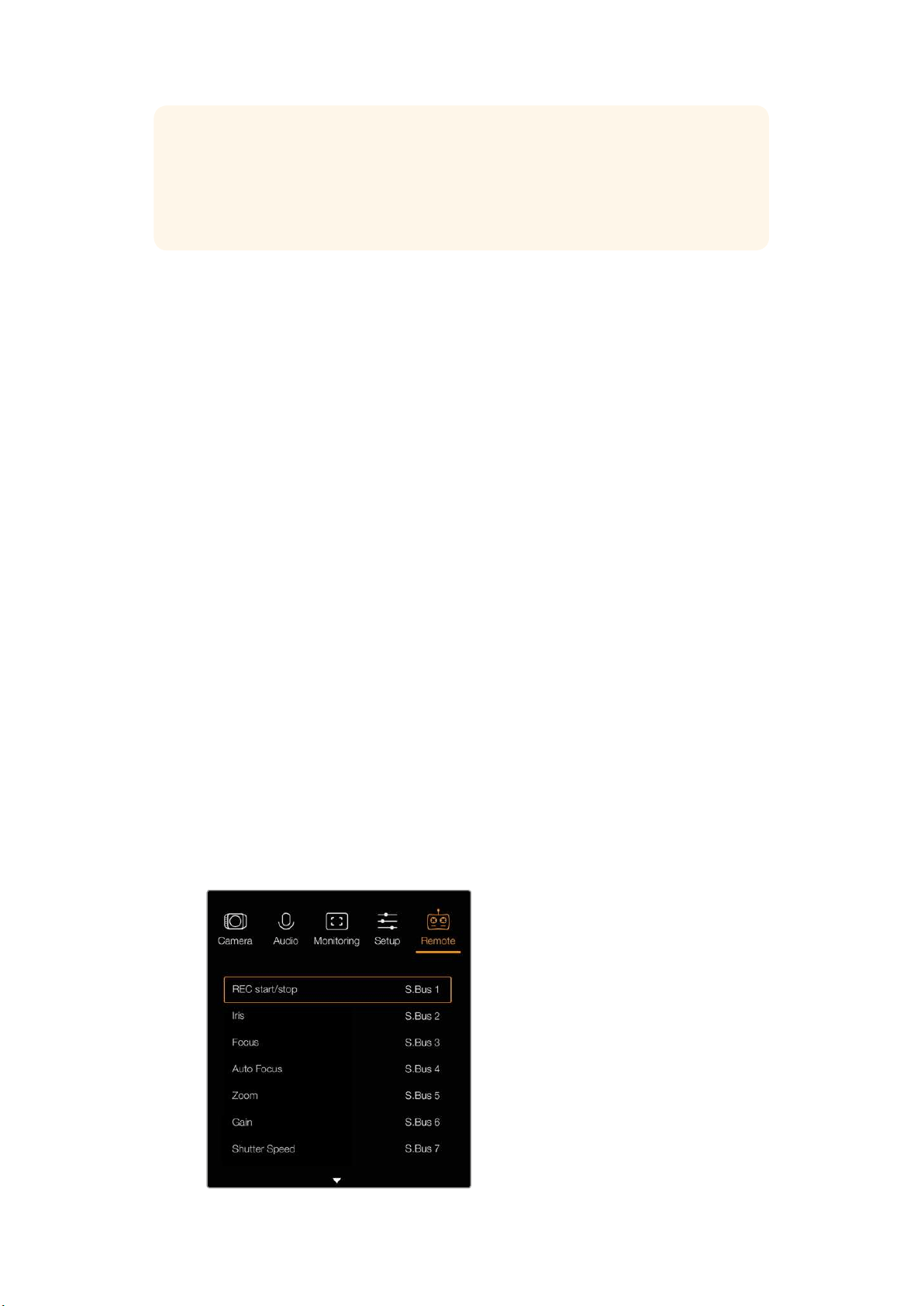
Remote Settings
Blackmagic Micro Studio Camera 4K features an additional menu for setting remote functions
using the S.Bus protocol. This protocol uses 1 connection to control up to 17 channels, and each
of these channels can be mapped to a specific camera function. S.Bus receivers and decoders
can be found in most major hobby stores online as they are often used for radio remote control
of airplane and helicopter models.
Remote settings – Blackmagic Micro Studio Camera 4K.
25Settings

Assigning Camera Functions to S.Bus Channels
If you are using S.Bus to control your Blackmagic Micro Studio Camera 4K, you can use the
‘remote’ menu to assign the following functions to individual S.Bus channels:
Trigger record
Iris
Focus
Auto focus
Zoom
Gain
Shutter speed
White balance
Audio levels
Frame rate
To assign functions to individual S.Bus channels, simply select the function you wish to control
and assign an available channel using the ‘up,’ ‘down’ and ‘set’ buttons.
Standard radio transmitters for remote control vehicles that support the S.Bus protocol are usually
setup with control ranges built into their controller output, so that all you need to do is assign camera
functions to the correct individual S.Bus channels for remote control of your camera functions.
You can also use the S.Bus protocol to develop your own sophisticated custom control
solutions.
Developing a Custom Controller
If you would like to develop your own custom camera control solutions, you can use the S.Bus
input on the expansion cable as a way to interface camera functions on Blackmagic Micro
Studio Camera 4K.
When sending commands via the S.Bus input to Micro Studio Camera 4K, the input values will
need to be between 44 and 212 in order to be interpreted by the camera. A value of 128 is
considered to be the midpoint or neutral position when using a radio control transmitter.
The way in which specific commands are sent to the camera will depend upon how you have
mapped the camera functions to your controller.
There are two ways to map the commands to the controls.
The first type maps settings to specific ranges of the input so that sending a value
within a certain range will trigger a particular setting.
For example, the f-stop settings on a lens from f1.8 to f22 will be distributed along the
entire range of 44 to 212. Sending a value between 44 and 51 would set the lens to f1.8.
These values will then continue along the entire range so that sending a value between
206 and 212 would select f22. Zoom and focus changes are controlled the same way.
f1.8 f2 f2.8 f4 f5.6 f8 f11 f16 f22
44–61 62–79 80–97 98–115 116–133 134–151 152–169 170–197 198–212
The second type of control registers any change from the neutral value of 128 to a
value above or below and then back to the neutral point. This will be considered by the
camera as a valid toggle signal, which increases or decreases the assigned settings.
Settings like the REC trigger, autofocus, gain, shutter speed, white balance and frame
rate work on this basis.
26Settings
You could assign camera functions to a control like a spring loaded joystick which
snaps back to a neutral center point after each movement up or down. In this example a
value of 44 would represent the maximum downward position of the joystick and 212
would represent the maximum upward position, while the center functions as a neutral
point with a value of 128.
Maximum 212
Neutral Center Point
128
Minimum
44
For example, if your gain settings are mapped to a joystick in this way, then after each
upward movement of the joystick it would return to the neutral point in the center which
toggles the camera to increase gain by one increment, say from 0dB to 6dB.
You could also send this same information in numerical form to another type of controller that
uses numerical values. In this case you would send a value of 128, followed by a value above
128 such as 212, and then back to 128 again. The camera will register this as an increment
command and change the gain from 0dB to 6dB.
The way in which you assign commands will depend upon the kind of control system that you
are using to control your camera and the type of control that you want to assign. Spring loaded
controls that snap back to a neutral point are very common on radio control transmitters for
model aircraft and drones.
If you are using a Futaba style remote control, some functions will be more suited to the rotating
dials or analogue sticks, whilst other functions will be more suited to the switches.
Button Settings
Adjusting Lens Settings
Blackmagic Studio Camera supports electronic lens control, which allows you to adjust lens
settings such as aperture and auto focus. The focus peaking feature creates a green edge
around the sharpest parts of the image so you can easily confirm your focus. Focus peaking is
only visible on the LCD and does not affect the SDI output.
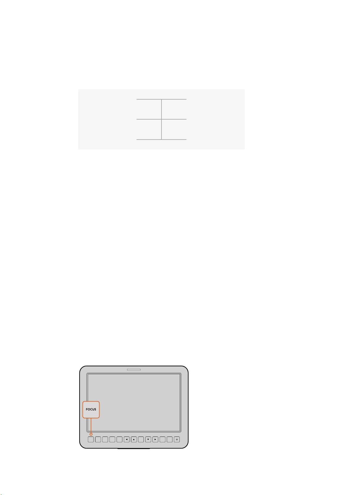
Focus Button
When using the Studio Camera with an auto focus lens, press the focus button for focus
peaking or auto focus. Press the focus button once to auto focus. A quick double press
of the focus button activates focus peaking.
When using a manual lens, press the focus button once for focus peaking.
FOCUS IRIS PTT PGM LUT SET DISPLAY MENU
Press the focus button
once to auto focus.
Aquick double press
of the focus button
activates focus peaking.
27Settings
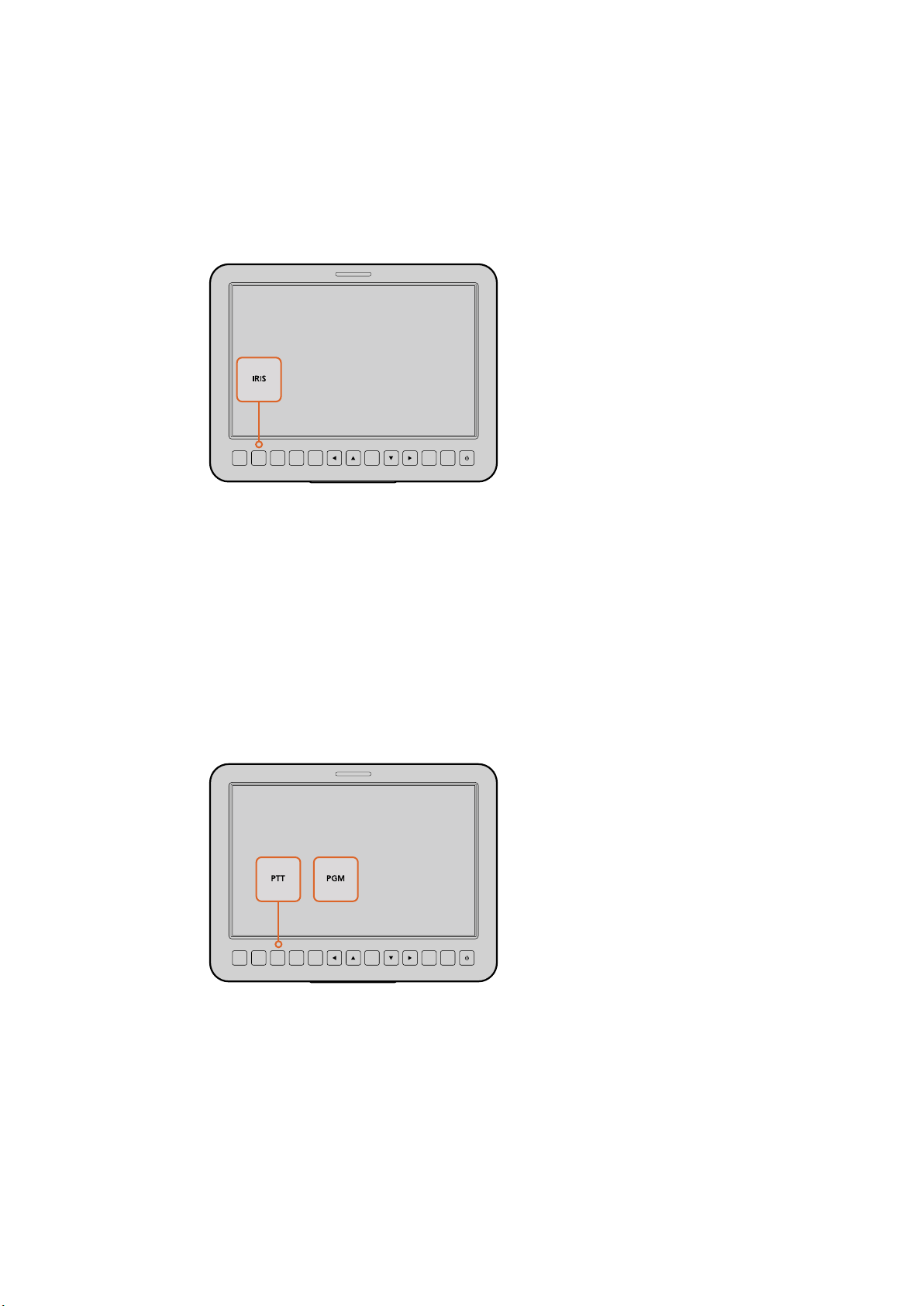
Iris Button
When using video dynamic range settings, a single press of the iris button will set an
average exposure based on the highlights and shadows in your shot. When using film
dynamic range settings, pressing the iris button sets your exposure to accommodate
the brightest highlight in your shot. To set your aperture manually on your Studio
camera, press the up and down menu navigation buttons.
Additional Settings
Push to Talk (PTT) Button
When doing live production it is vital that camera operators can talk to the director and
others within the control room. Simply press and hold the button to begin talking. Press
twice in quick succession for hands free communication. Press again to revert to the
default behavior.
Program (PGM) Button
It is sometimes important for camera operators to see the program output, rather than
just the view from their own camera. Press the button to toggle between live camera
output and the program output from a switcher control room. You can use either the
SDI input, or user upgradable optical fiber input to connect your external video source.
Look Up Table (LUT) Button
Currently not implemented.
Left, Up, Down, Right Buttons
Use these buttons to navigate the menus.
Set Button
Use this button to confirm your menu selections.
FOCUS IRIS PTT PGM LUT SET DISPLAY MENU
Press the iris button
for auto exposure or
use the up and down
navigation controls
formanual exposure.
FOCUS IRIS PTT PGM LUT SET DISPLAY MENU
The Studio Camera
features settings
like PTT and PGM
which are essential
for live production.
28Settings
Display Button
Press this button to display useful information on your Studio Camera’s 10” monitor,
including:
Frame guides with camera and lens settings such as camera number, video format and
frame rate, shutter speed, white balance, battery life, gain setting and f-stop number.
Press the Disp button again to turn overlays off and monitor the image only. Overlays
are visible on the 10” monitor. The SDI output is always clean.
NOTE Blackmagic Studio Camera 2 and Studio Camera 4K 2 do not have
internal batteries so will not display battery life remaining.
Menu Button
Press this button to bring up the menu and then use the arrow buttons to navigate.
Power Button
Press the power button to turn on the Blackmagic Studio Camera. Press and hold to
turn the camera off.
Camera Video Output
Connecting to Video Switchers
Blackmagic Studio Cameras output 10-bit 4:2:2 video so you can connect to broadcast
switchers and other SDI video equipment. With the user upgradable SFP module installed you
can connect via optical fiber, which means ATEM Camera Converters are not required at the
camera end.
If you’re using a Blackmagic Studio Camera HD or Studio Camera 4K, you can easily view the
Program (PGM) output from the switcher by connecting it to your Studio Camera’s SDI input,
orto the optical fiber input when the user upgradable SFP module is installed.
Connect your Studio Camera to a switcher via SDI, or via
optical fiber with user upgradable SFP module installed
Blackmagic Studio Camera also features a reference input which allows multiple cameras to be
genlocked to a blackburst or tri-level reference signal. Genlocking cameras, VTRs and other
devices to an external reference signal helps to eliminate timing errors which may result in the
picture jumping when switching between different sources.
OPTICAL OUT
OPTICAL IN
SDI OUT
SDI IN
REF
12V
OPTICAL OUT
OPTICAL IN
SDI OUT
SDI IN
29Camera Video Output
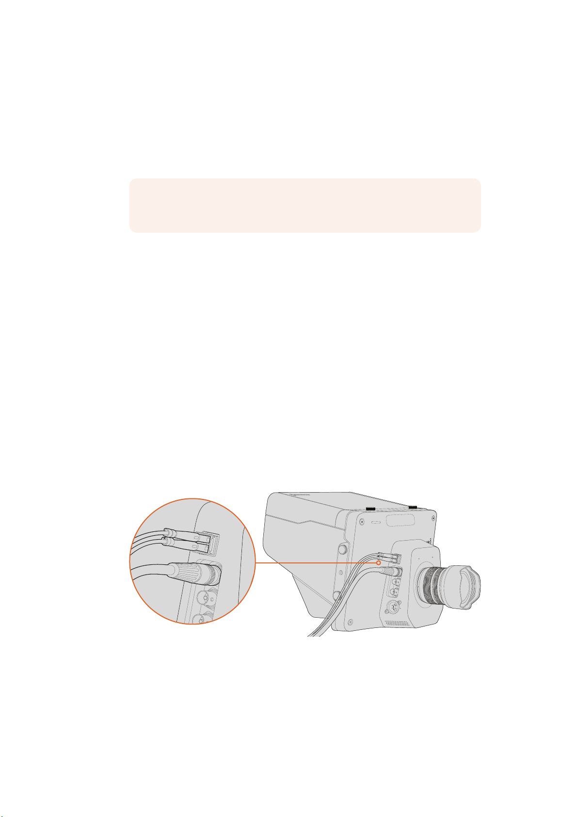
Connecting to Recorders
If you simply wish to record your Studio Camera’s output, you can connect the SDI output to the
SDI input of an SSD recorder such as the Blackmagic HyperDeck Shuttle. The SDI output from
the HyperDeck can then be connected to the Studio Camera’s SDI input, so you can view your
recordings on the camera’s LCD.
Connect the camera’s SDI output to the HyperDeck’s SDI input and connect the
HyperDeck’s SDI output to the camera’s SDI input to view your recordings.
Remote Record
Blackmagic Micro Studio Camera 4K automatically sends a signal via the SDI or HDMI output
that will trigger recording when connected to equipment that supports the trigger record
feature, such as Blackmagic Video Assist.
To trigger recording on your external equipment, you can connect a hand grip with a record
trigger switch to your camera via the LANC or S.Bus connectors on the expansion cable.
Thenwhen you press record on the hand grip, your external equipment will start recording, and
will stop recording when you press record again.
You will also need to set your equipment to enable SDI or HDMI trigger recording to make sure
it responds to the trigger signal from your Micro Studio Camera 4K.
The Blackmagic SDI Control Protocol can also be used to trigger remote recording.
For more details, refer to the developer information section in this manual.
RAW SDI Output
Blackmagic Micro Studio Camera 4K also has a ‘RAW’ mode which outputs bayered sensor data
over the SDI output. This allows you to perform your own debayering of the image data from
the sensor.
For more information refer to the ‘RAW SDI Output’ section in the developer information section
in this manual.
+12V POWER HDMI IN HDMI OUT SDI IN SDI OUT
SDI IN SDI OUT
30Camera Video Output

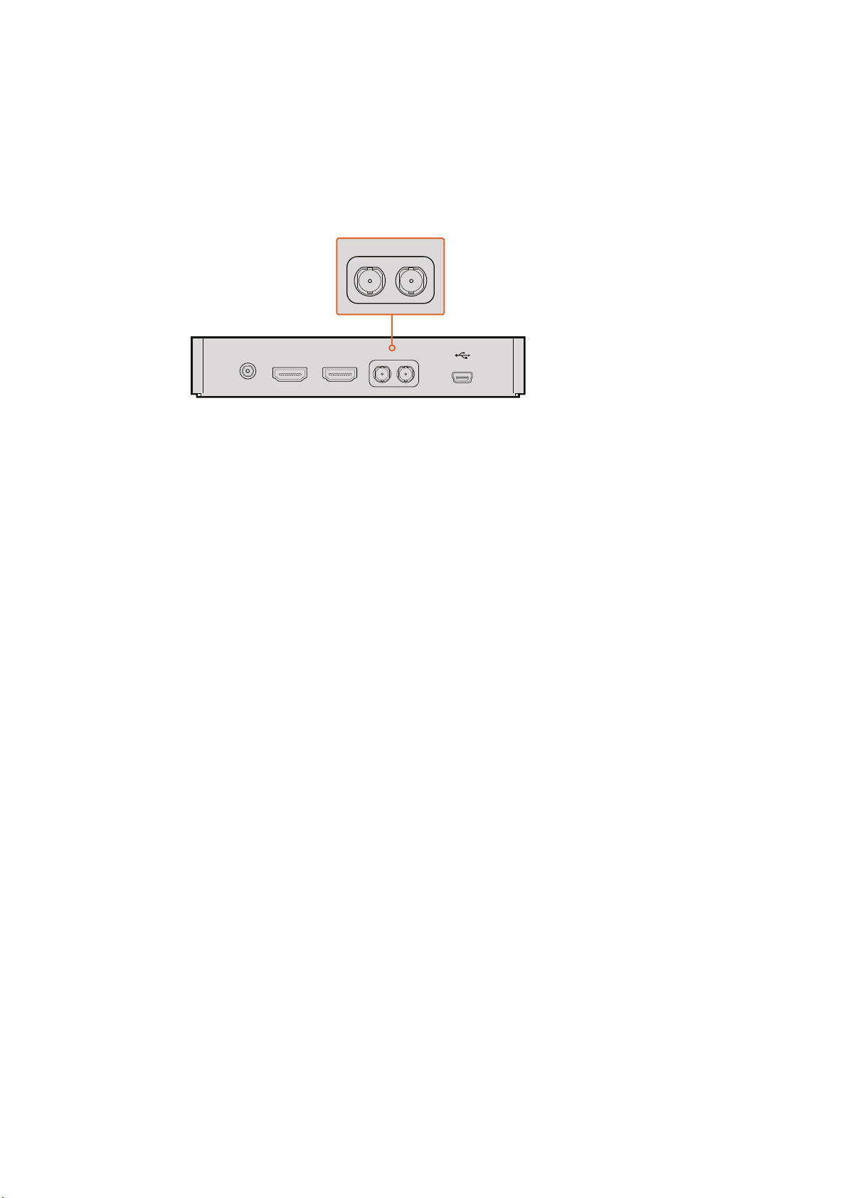
Connecting Tally using the
Blackmagic3G-SDI Shield for Arduino
If you are using an SDI switcher with a tally output connector, you can connect the tally outputs
to a Blackmagic 3G-SDI Shield for Arduino to send tally signals to your Blackmagic Studio
Cameras. This means you can still get tally on your Blackmagic cameras via the SDI program
return feed even if you aren’t using an ATEM switcher.
For example, the switcher’s parallel tally port connects to pins D2 - D9 of your Blackmagic
shieldand the shield’s SDI output is connected to all Blackmagic cameras via a distribution
amplifier, such as a Blackmagic Mini Converter SDI Distribution. This way you can send tally to
8separate Blackmagic cameras.
The Blackmagic camera number must match the switcher’s tally outputs, which means you may
need to wire a custom connector to make sure the pins correspond to each camera number.
The common GND from the switcher’s tally connector must be connected to the GND pin of the
Blackmagic 3G-SDI Shield.
Below is a configuration example showing how the Blackmagic camera numbers match the tally
outputs from the switcher, which are then connected to the pins on the Blackmagic 3G-SDI
Shield for Arduino.
Blackmagic Camera Number Switcher Input Number Arduino Pin
1 1 D2
2 2 D3
3 3 D4
4 4 D5
5 5 D6
6 6 D7
7 7 D8
8 8 D9
The example sketch below shows how the Blackmagic 3G-SDI Shield for Arduino is
programmed to send a tally signal to the camera that has been switched to the program output.
All SDI switchers that have open collector outputs are configurable for tally using the
Blackmagic 3G-SDI Shield for Arduino. For more information, download the Blackmagic 3G-SDI
Shield for Arduino. instruction manual from the Blackmagic Design support center at www.
blackmagicdesign.com/support.
31Connecting Tally using the Blackmagic3G-SDI Shield for Arduino
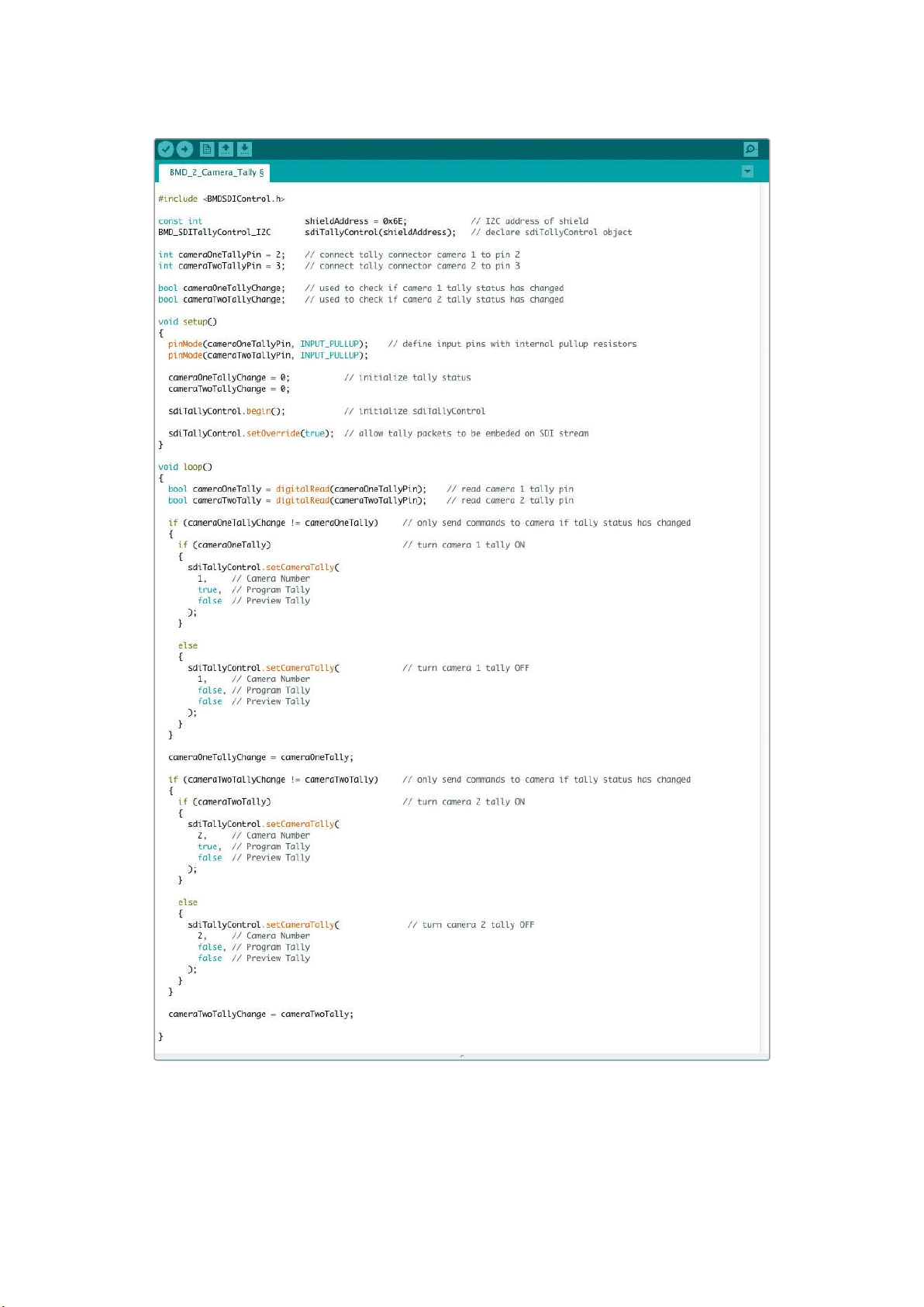
The example sketch above shows how the Blackmagic 3G-SDI Shield for Arduino is programmed
to detect a tally signal for input 1 or 2 via the switcher’s tally output, and then embed that tally signal
into the shield’s SDI output. The tally light on the corresponding camera will then illuminate.
32Connecting Tally using the Blackmagic3G-SDI Shield for Arduino
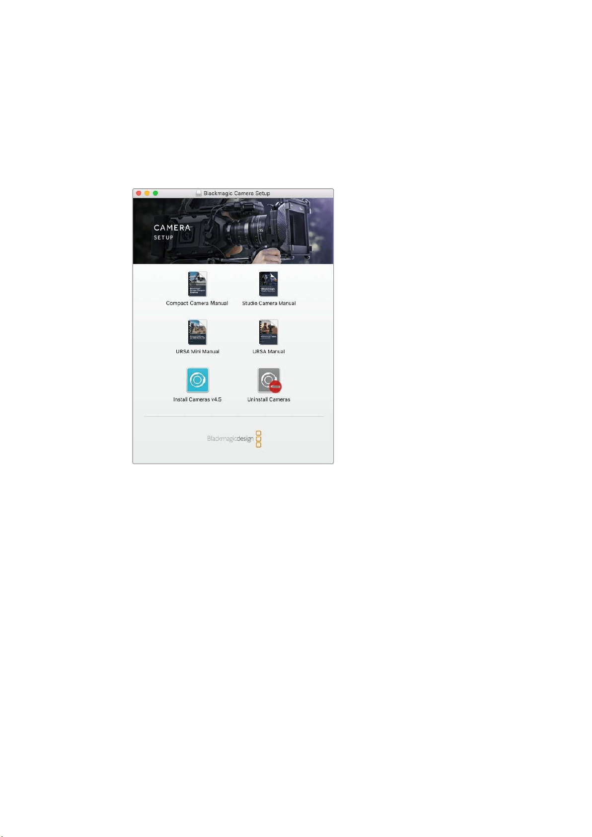
Blackmagic Camera Setup
How to Update Your Camera Software on Mac OS X
After downloading the ‘Blackmagic Camera Setup’ software, unzip the downloaded file and
double click on the .dmg disk image file. Launch the ‘Blackmagic Camera Setup’ installer and
follow the onscreen instructions.
Blackmagic Camera Setup software.
How to Update Your Camera Software on Windows
After downloading the ‘Blackmagic Camera Setup’ software and unzipping the downloaded file,
you should see a ‘Blackmagic Camera Setup’ installer window. Double click on the installer icon
and follow the onscreen prompts to complete the installation.
After the installation is complete, click on the Windows ‘start’ menu, and go to ‘all programs’.
Click on the Blackmagic Design folder to open the Blackmagic Camera setup software and
instruction manuals.
How to Update your Camera’s Internal Software
After installing the latest Blackmagic Camera setup software on your computer, connect a
USBcable between the computer and your camera. The Mini-B USB 2.0 port is located on the
underside of the camera.
Launch ‘Blackmagic Camera Setup’ and follow the onscreen prompts to update the
camera software.
33Blackmagic Camera Setup
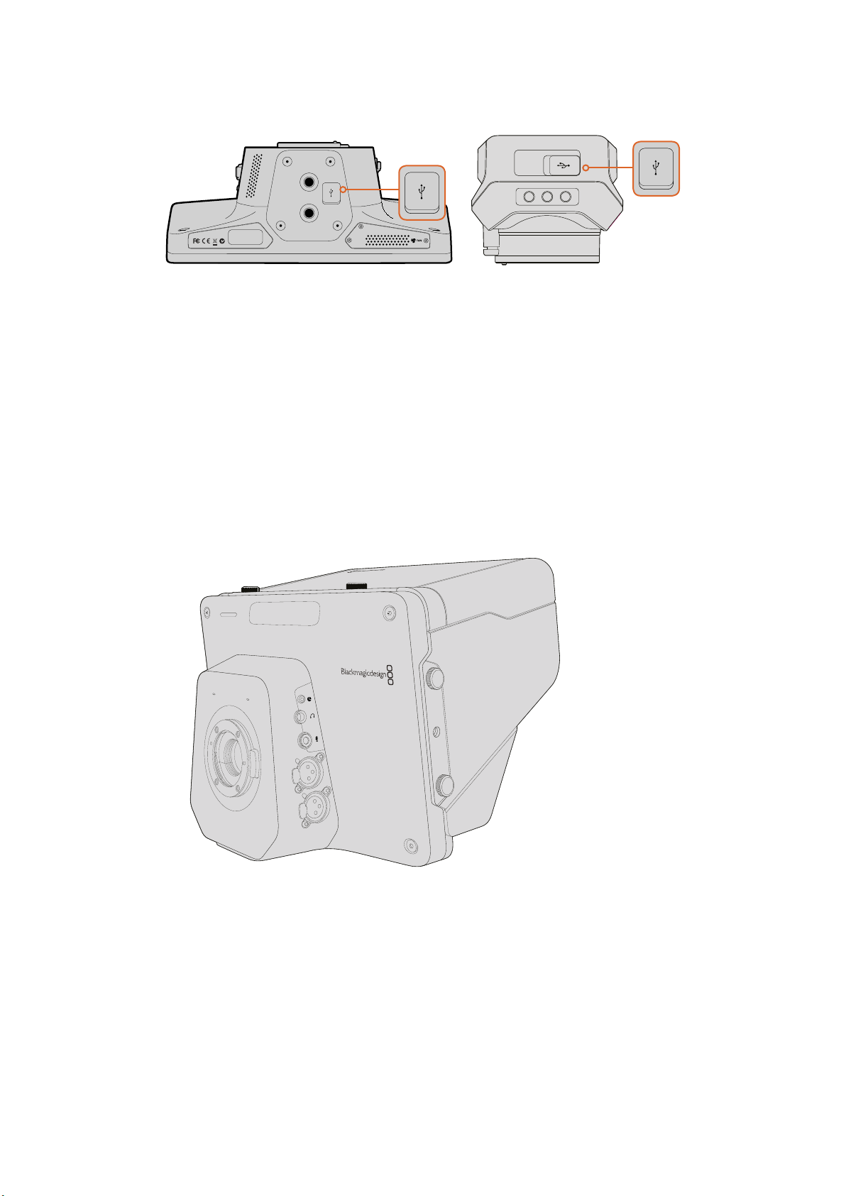
The Mini-B USB 2.0 ports are located on the underside of the cameras.
Attaching Accessories
Sun Shade
The Studio Cameras include a foldable sun shade to shade the LCD in bright conditions and
ensure optimum viewing is possible at all times.
1 Locate the 6 thumbscrews that are included with your Studio Camera.
2 Align the holes in the sun shade with the camera’s mounting points and screw in
2thumbscrews to the top and each side of the camera to firmly secure the sun shade.
Other Accessories
For studio use, you might want to mount the camera on a pedestal and add rails for large
broadcast lenses and teleprompters. For outside broadcast use, your may want to attach
microphones, external batteries, or LANC remote controllers. The camera includes two 3/8”
mounting points on the bottom, and ten 1/4” mounting points on the sides and the top.
This means you have the flexibility to customize your rig for any size production.
1
1
3
PUSH
2
2
1
3
PUSH
2
34Attaching Accessories
Using ATEM Software Control
Introducing Camera Control
Your Blackmagic Studio Camera can be controlled from an ATEM switcher using the Camera
Control feature in ATEM Software Control. Clicking on the Camera button opens the camera
control feature. Settings such as iris, gain, focus and zoom control are easily adjusted using
compatible lenses, plus you can color balance cameras and create unique looks using the
DaVinci Resolve primary color corrector.
The ATEM switcher control works by broadcasting camera control packets via all the non down
converted SDI outputs of an ATEM switcher. So this means you can connect an SDI output of an
ATEM switcher to your camera’s video input, your camera will detect the control packets in the
SDI link and allow you to control features in the camera itself. You can control your camera via
both regular SDI, or via user upgradable optical fiber when the SFP module is installed.
ATEM Camera Control.
Connecting via SDI
1 Connect your Blackmagic Studio Camera’s SDI Out to any SDI In on the ATEM switcher.
2 Connect any one of the ATEM switcher’s SDI outputs, except down converted or multi
view outputs, to your Studio Camera’s SDI In. Camera control signals are not sent via
the multi view and down converted SDI outputs.
3 On your Blackmagic Studio Camera, press Menu. Navigate to Studio Settings>Camera
Number and set it to match the switcher input. For example, if studio camera 1 is
connected to Cam 1 on the ATEM switcher, the camera number must also be set to 1.
This ensures tally is sent to the correct camera.
35Using ATEM Software Control
Connect your Blackmagic Studio Camera to any of the ATEM switcher’s SDI inputs.
Connecting via Optical Fiber
1 With the user upgradable optical fiber SFP module installed in your Studio Camera,
connect the Optical Out/In to the Optical Out/In on an ATEM Studio Converter.
2 Connect a suitable SDI out from ATEM Studio Converter to any SDI In on the
ATEM switcher.
3 Connect any one of the ATEM switcher’s SDI outputs, except down converted or multi
view outputs to ATEM Studio Converter’s SDI In. Camera control signals are not sent via
the multi view and down converted SDI outputs.
4 On your Blackmagic Studio Camera, press Menu. Navigate to Studio Settings>Camera
Number and set it to match the switcher input. For example, if studio camera 1 is
connected to Cam 1 on the ATEM switcher, your camera number must also be set to 1.
This ensures tally is sent to the correct camera.
Open ATEM Software Control Preferences and set the switcher’s button mapping to make sure
you are switching the right camera with correct tally. Now you have a video connection from the
switcher to your Blackmagic Studio Camera, you can also get the advantage of live tally
indicators on your camera, as well as being able to view the program feed of the switcher by
pressing your camera’s PGM button.
Connect multiple Blackmagic Studio Cameras via optical fiber using an ATEM Studio Converter.
PUSH PUSH
CONTROL
USB 2.0 HDMI IN
SDI INPUTS REF IN AUX 1-3 PREVIEW PROGRAM OUTPUTS MULTI-VIEW ANALOG AUDIO IN
STEREO IN
REMOTE
ANALOG AUDIO OUT
CH 1
All SDI and HDMI video connections are
SD, HD and Ultra HD switchable unless indicated
CH 2CH 1 CH 2
IN
1
IN
2
IN
1
IN
3
IN
4
IN
5
IN
6
IN
7
IN
8
IN
9
IN
10
2
1 3
2
1
HD HD HD
PROGRAM OUTPUTS
2
1
HD
HDMI IN
SDI INPUTS
IN
1
IN
2
IN
1
IN
3
IN
4
IN
5
IN
6
IN
7
IN
8
IN
9
IN
10
4321
OPTICAL OUT/IN
SDI OUT
L R
RL
USB 2.0
+12V BACKUP
POWER
OPTICAL OUT/IN
SDI OUT
L R
ANALOG AUDIO OUT OPTICAL OUT/IN
SDI OUT
L R
ANALOG AUDIO OUT OPTICAL OUT/IN
SDI OUT
L
OUT
R
ANALOG AUDIO OUTANALOG AUDIO OUT
IN
PGM SDI
OUT
IN
MIC
OUT
IN
H/PHONE
AES/EBU TALKBACK LOOPS
IN
PGM SDI
IN
1
OPTICAL OUT/IN
SDI OUT
L R
ANALOG AUDIO OUT
36Using ATEM Software Control
Using Camera Control
Launch ATEM Software Control and click on the Camera button located at the bottom of the
software window. You’ll see a row of labeled camera controllers containing tools to adjust and
refine each camera’s image. The controllers are easy to use. Simply click the buttons using your
mouse, or click and drag to adjust.
Camera Control Selection
The button row at the top of the camera control page lets you select the camera
number you would like to control. If you have more cameras that fit onto the window
size, or you are running the color corrector window, then you can use these buttons to
select between which camera you would like to control. If you are using an Aux output
for monitoring your camera control, pushing these buttons to change the camera to
control will also send that camera’s video output to the Aux output. Your chosen Aux
output for camera control can be set in the general switcher settings.
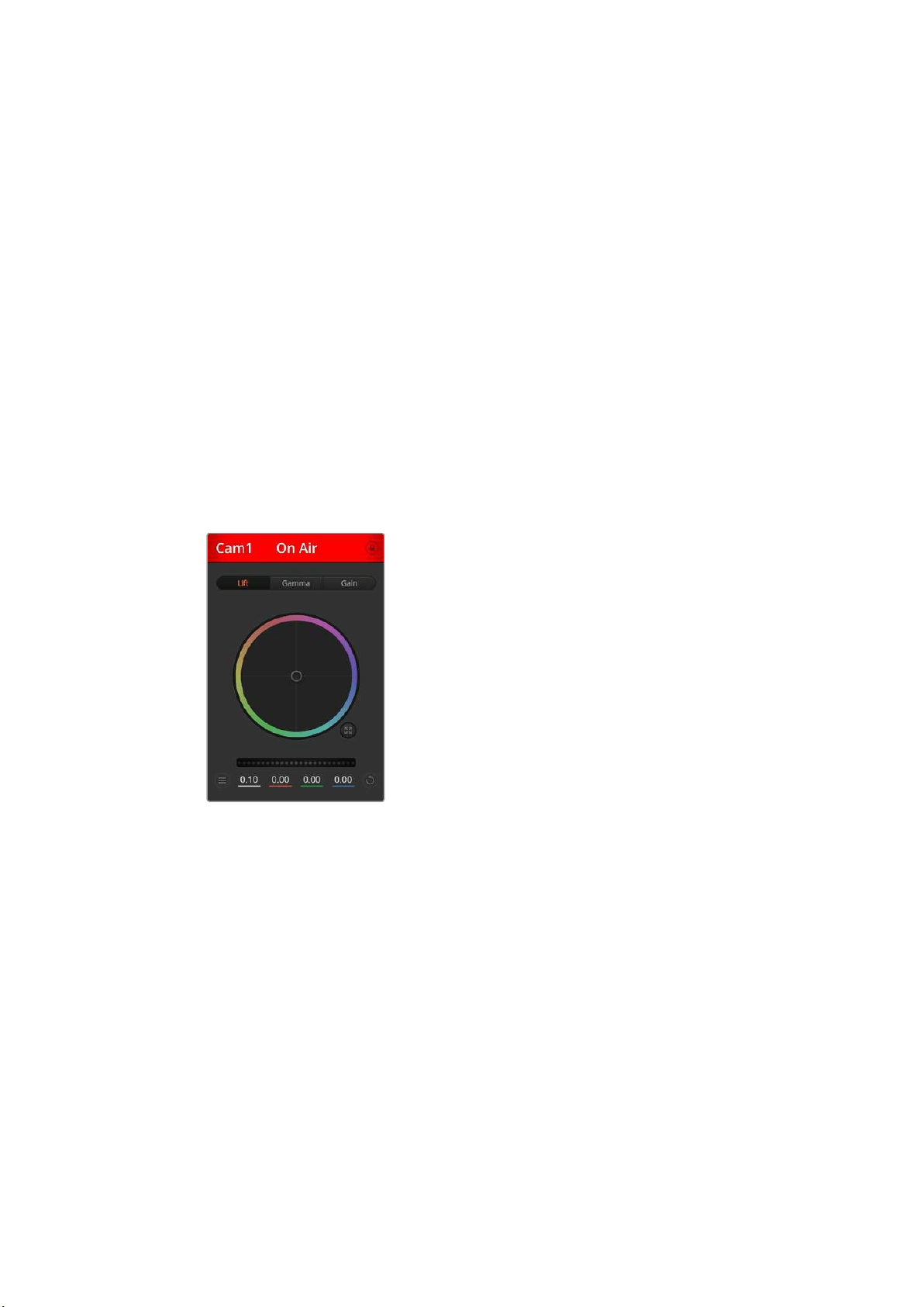
Channel Status
The channel status at the top of each camera controller displays the camera label, On
Air indicator and lock button. Press the lock button to lock all the controls for a specific
camera. When on air, the channel status illuminates red and displays the On Air alert.
Color Wheel
The color wheel is a powerful feature of the DaVinci Resolve color corrector and used to make
color adjustments to each YRGB channel’s lift, gamma and gain settings. You can select which
setting to adjust by clicking on the three selection buttons above the color wheel.
Master Wheel
Use the master wheel below the color wheel to make contrast adjustments to all YRGB
channels at once, or luminance only for each lift, gamma or gain setting.
Camera Settings
The camera settings button near the bottom left of the master wheel lets you turn on the color
bars feature in Blackmagic Studio Cameras, Micro Studio Cameras and URSA mini, plus adjust
detail settings for each camera’s picture signal.
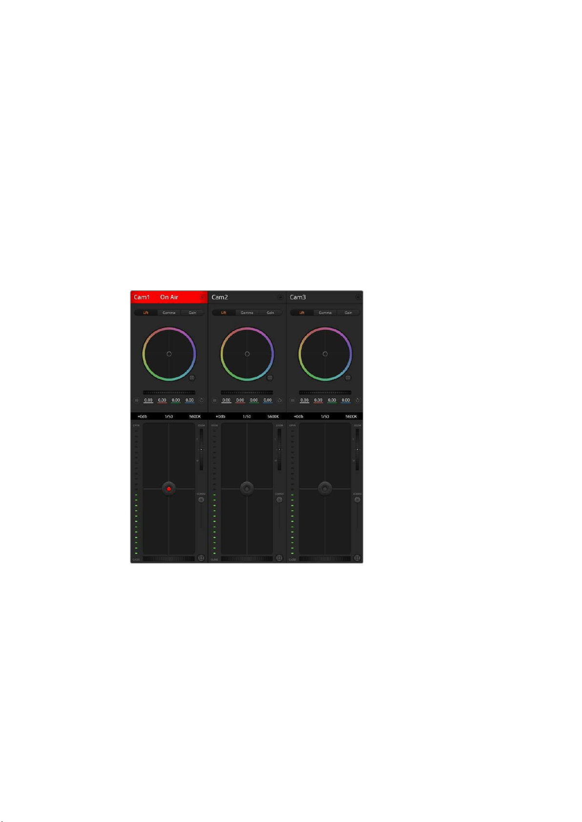
Each camera controller
displays the channel
status so you know which
camera is on air. Use the
color wheels to adjust
each YRGB channel’s lift,
gamma and gain settings.
37Using ATEM Software Control
Show/Hide Color Bars
Blackmagic cameras have a color bars feature built in which you can turn on or off by
selecting ‘show’ or ‘hide’ color bars. This feature can be very useful for visually identifying
individual cameras while setting up for your live production. Color bars also provide an
audio tone so you can easily check and set the audio levels from each camera.
Detail
Use this setting to sharpen the image from your cameras live. Decrease or increase the
level of sharpening by selecting: Detail off, detail default for low sharpening, medium
detail, and high detail.
Reset Buttons
The reset button near the bottom right of each camera controller lets you easily choose color
correction settings to reset, copy or paste. Each color wheel also has its own reset button.
Press to restore a setting to its default state, or copy/paste a setting. Locked controllers are not
affected by the Paste feature.
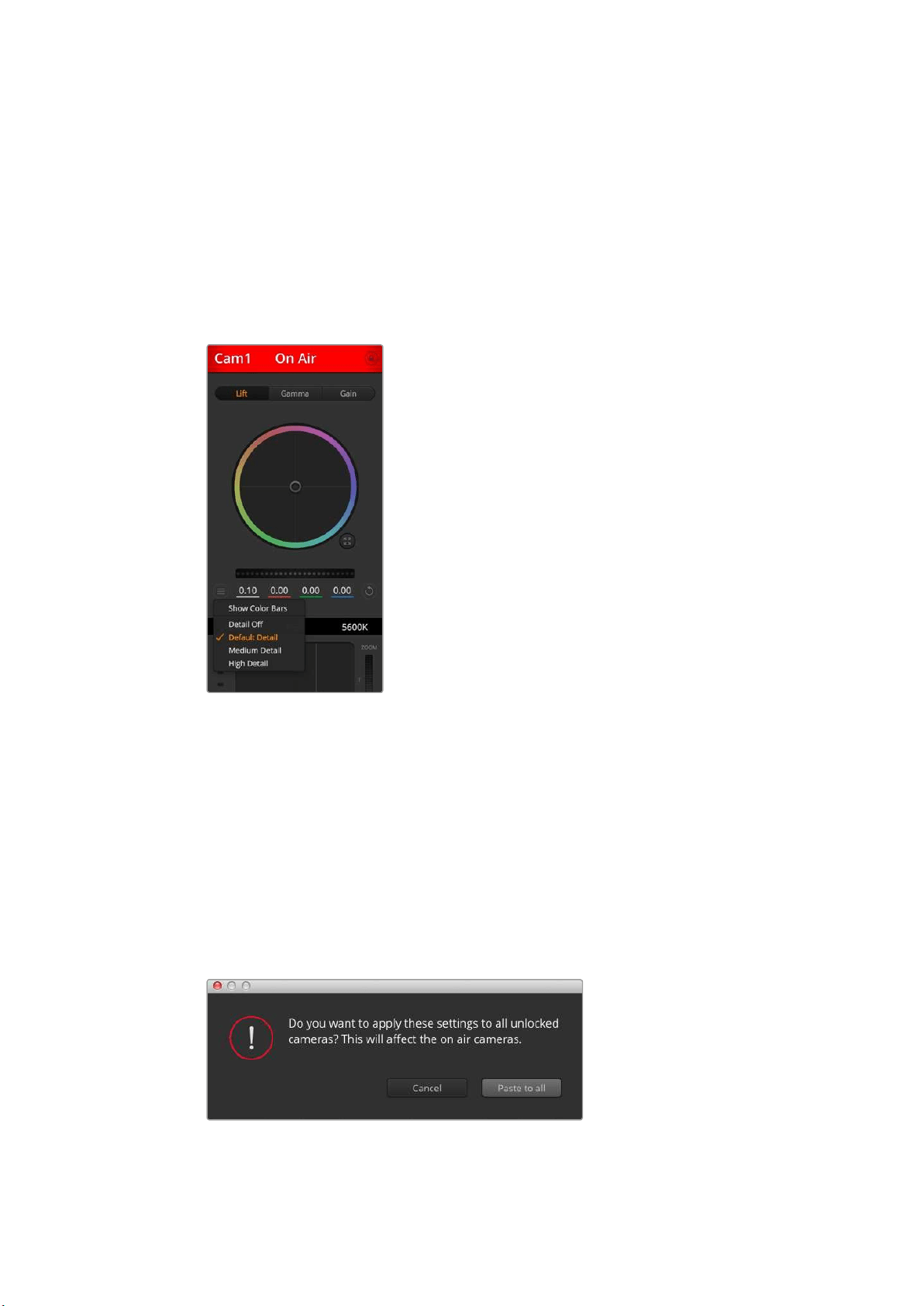
The master reset button on the bottom right corner of the color corrector panel lets you reset lift,
gamma and gain color wheels plus Contrast, Hue, Saturation and Lum Mix settings. You can paste
color correction settings to camera controllers individually, or all cameras at once for a unified
look. Iris, focus, coarse and pedestal settings are not affected by the Paste feature. When
applying Paste to all, a warning message will appear asking you to confirm your action. This is
so you don’t accidentally paste new settings to any unlocked cameras that are currently on air.
When applying Paste to all, a warning message will appear asking
you to confirm your action. This is so you don’t accidentally paste
new settings to any unlocked cameras that are currently on air.
The camera settings
button lets you turn
color bars on or off
and adjust the in-
camera sharpening
of connected
Blackmagic cameras.
38Using ATEM Software Control
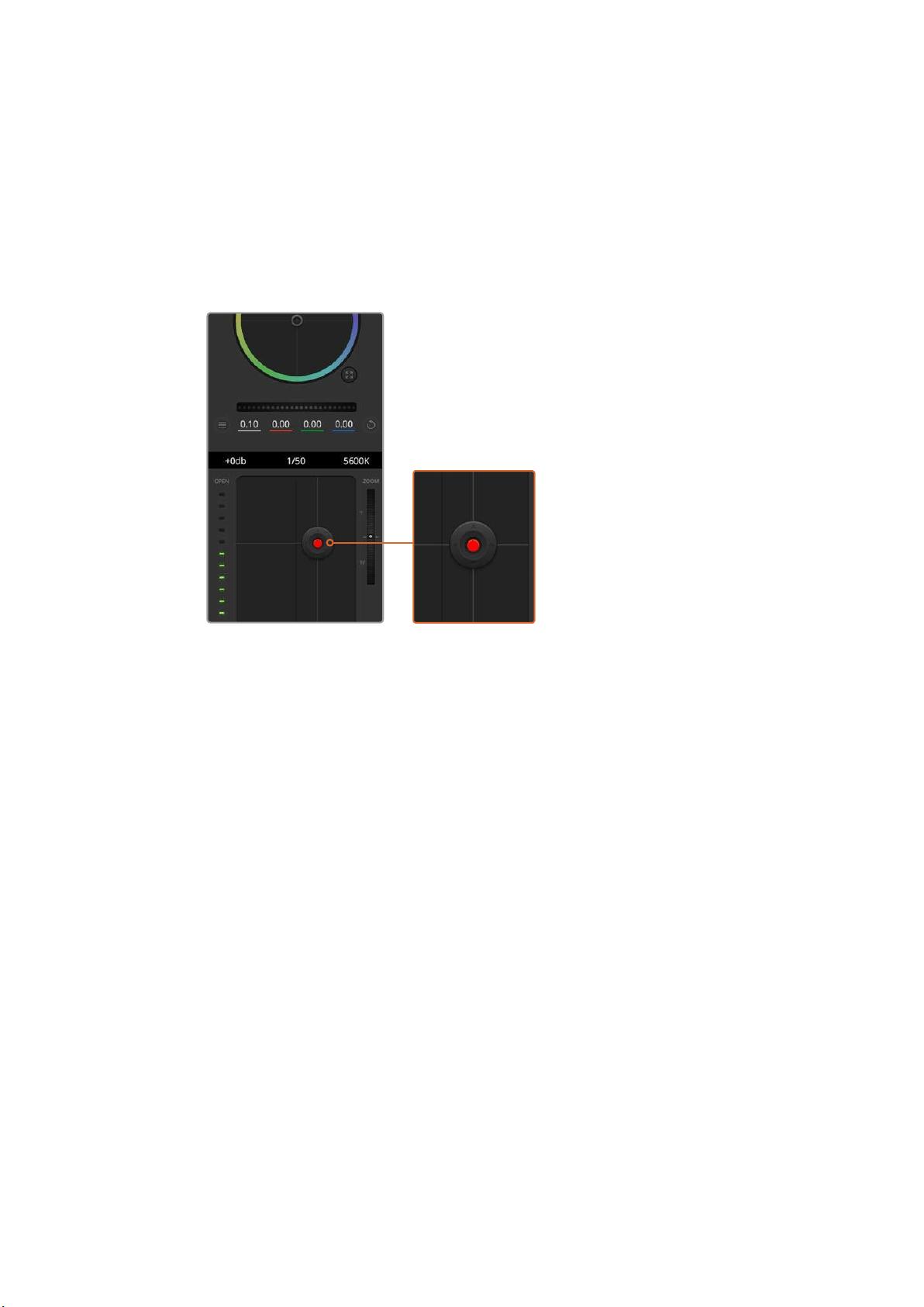
Iris/Pedestal Control
The iris/pedestal control is located within the cross hairs of each camera controller. The control
illuminates red when its camera is on air.
To open or close the iris, drag the control up or down. Holding the shift key allows only iris
adjustments.
To darken or lift the pedestal, drag the control left or right. Holding the command key on a Mac,
or the Control key on Windows, allows only pedestal adjustments.
The iris/pedestal control illuminates red
when its respective camera is on air.
Zoom Control
When using compatible lenses with an electronic zoom feature, you can zoom your lens in and
out using the zoom control. The controller works just like the zoom rocker on a lens, with
telephoto on one end, and wide angle on the other. Click on the zoom control, located above
the coarse slider, and drag up to zoom in, or drag down to zoom out.
If your lens does not have active lens control or your camera does not support zoom control via
the SDI camera control protocol then these settings will have no effect. If you are using
Blackmagic Studio Camera or Blackmagic Studio Camera 4K, please make sure you have
updated your camera software to v1.9.11 or later to ensure your camera has support for
controlling MFT lenses with active zoom.
Coarse Setting
The coarse setting is located to the left of the iris/pedestal control and is used to limit the iris
range. This feature helps you prevent over exposed images from going to air.
To set your coarse threshold, completely open the iris using the iris control, then drag the
coarse setting up or down to set optimum exposure. Now when you adjust the iris, the coarse
threshold will prevent it from going above optimum exposure.
Iris Indicator
The iris indicator is located to the right of the iris/pedestal control and displays a visual
reference so you can easily see how open or closed the lens aperture is. The iris
indicator is affected by the coarse setting.
39Using ATEM Software Control
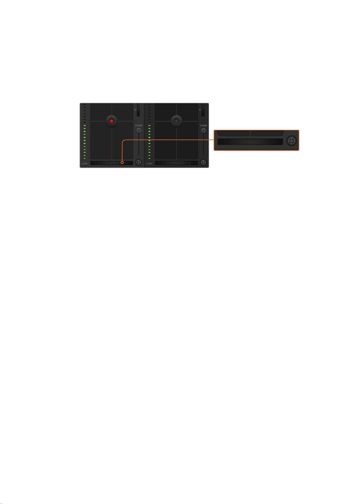
Auto Focus Button
The auto focus button is located at the bottom left corner of each camera controller. Press to
automatically set the focus when you have an active lens that supports electronic focus
adjustments. It’s important to know that while most lenses support electronic focus, some
lenses can be set to manual or auto focus modes, and so you need to ensure your lens is set to
auto focus mode. Sometimes this is set by sliding the focus ring on the lens forward or backward.
Click on the auto focus button or drag the manual focus
adjustment left or right to focus a compatible lens.
Manual Focus Adjustment
When you want to adjust the focus on your camera manually, you can use the focus adjustment
located at the bottom of each camera controller. Drag the wheel control left or right to manually
adjust focus while viewing the video feed from the camera to ensure your image is nice
and sharp.
Camera Gain
The camera gain setting allows you to turn on additional gain in your camera. This is important
when you are operating in low light conditions and need extra gain in the front end of your
camera to avoid your images being under exposed. You can decrease or increase gain by
clicking on the left or right arrows on the dB gain setting.
You can turn on some gain when you need it, such as outdoor shoots when the light fades at sunset
and you need to increase your image brightness. It’s worth noting that adding gain will increase noise
in your images.
Shutter Speed Control
The shutter speed control is located in the section between the color wheel and the iris/
pedestal control. Decrease or increase the shutter speed by hovering your mouse pointer over
the shutter speed indicator and then clicking on the left or right arrows.
If you see flicker in lights you can decrease your shutter speed to eliminate it. Decreasing
shutter speed is a good way to brighten your images without using camera gain because you
are increasing the exposure time of the image sensor. Increasing shutter speed will reduce
motion blur so can be used when you want action shots to be sharp and clean with minimal
motion blur.
White Balance
The white balance setting next to the shutter speed control can be adjusted by clicking on the
left or right arrows on each side of the color temperature indicator. Different light sources emit
warm or cool colors, so you can compensate by adjusting the white balance. This ensures the
whites in your image stay white.
40Using ATEM Software Control
Hovering your mouse pointer over the gain, shutter
speed and white balance indicators reveal arrows
you can click on to adjust their respective settings.
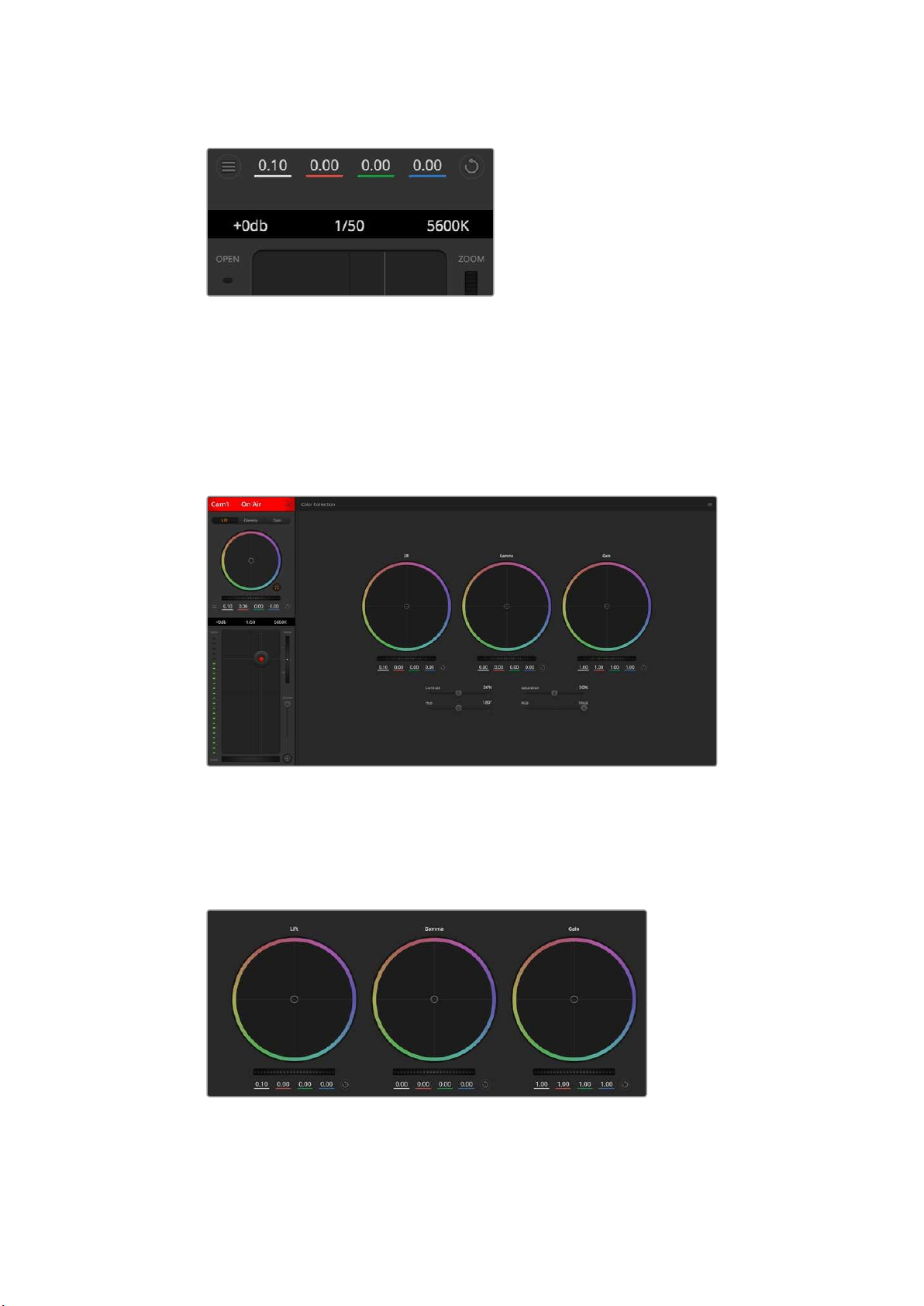
DaVinci Resolve Primary ColorCorrector
If you have a color correction background, then you can change the camera control from a
switcher style CCU interface to a user interface that’s more like a primary color corrector on a
post production color grading system.
Click on the DaVinci Resolve primary color corrector button
to expand the color correction window and adjust settings.
Color Wheels
The Lift/Gamma/Gain controls allow tonally specific yet overlapping regions of adjustment.
Inphotographic terms lift, gamma and gain corresponds to shadows, mid tones and highlights.
Lift, gamma and gain color wheels in the color corrector panel.
41Using ATEM Software Control
Use the color wheels in the following ways to make fine or aggressive adjustments:
Click and drag anywhere within the color ring: Note that you don’t need to drag the
color balance indicator itself. As the color balance indicator moves, the RGB parameters
underneath change to reflect the adjustments being made to each channel.
Shift-Click and drag within the color ring: Jumps the color balance indicator to the
absolute position of the pointer, letting you make faster and more extreme adjustments.
Double-click within the color ring: Resets the color adjustment without resetting the
master wheel adjustment for that control.
Click the reset control at the upper-right of a color ring: Resets both the color
balance control and its corresponding master wheel.
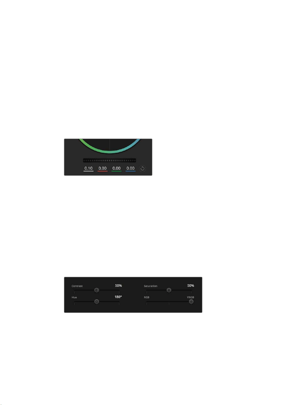
Master Wheels
Use the master wheels below the color wheels to adjust each YRGB channels’ lift,
gammaandgain controls.
Adjust the master wheels by dragging
the wheel control left or right.
To make adjustments using the master wheel:
Drag the master wheel left or right: Dragging to the left darkens the selected
parameter of the image, dragging to the right lightens that parameter. As you make
an adjustment, the YRGB parameters underneath change to reflect the adjustment
you’re making. To make a Y-only adjustment, hold down the ALT or Command key
and drag left or right. Because the color corrector uses YRGB processing, you
can get quite creative and create unique affects by adjusting the Y channel only.
Ychannel adjustments work best when the Lum Mix setting is set to the right side to
use YRGB processing vs the left side to use regular RGB processing. Normally, most
DaVinci Resolve colorists use the YRGB color corrector as you get a lot more control
of color balance without affecting overall gain, so you spend less time getting the
look you want.
Drag the sliders left or right to adjust Contrast,
Saturation, Hue and Lum Mix settings.
Contrast Setting
The Contrast setting gives you control over the distance between the darkest and lightest
values of an image. The effect is similar to making opposing adjustments using the lift and gain
master wheels. The default setting is 50%.
42Using ATEM Software Control

Saturation Setting
The Saturation setting increases or decreases the amount of color in the image. The default
setting is 50%.
Hue Setting
The Hue setting rotates all hues of the image around the full perimeter of the color wheel.
Thedefault setting of 180 degrees shows the original distribution of hues. Raising or lowering
this value rotates all hues forward or backward along the hue distribution as seen on a
color wheel.
Lum Mix Setting
The color corrector built into your Blackmagic Studio Camera is based on the DaVinci Resolve
primary color corrector. DaVinci has been building color correctors since the early 1980’s and
most Hollywood films are color graded on DaVinci Resolve than any other method.
This means the color corrector built into your Blackmagic Studio Camera has some unique and
creatively powerful features. The YRGB processing is one of those features.
When color grading, you can choose to use RGB processing, or YRGB processing. High end
colorists use YRGB processing because you have more precise control over color and you can
independently adjust the channels with better separation and more creative options.
When the Lum Mix control is set to the right side, you have the 100% output of the YRGB color
corrector. When you have the Lum Mix control set to the left side, you get 100% output of the
RGB corrector. You can set the Lum Mix to any position between the left and right to get a blend
of output from both the RGB and YRGB correctors.
Which is the correct setting to use? That’s up to you, as color correction is a pure creative
process and there is no right and wrong, and the best setting is what you like the most and
what you think looks good!
Synchronizing Settings
When connected, camera control signals are sent from the ATEM switcher to your Blackmagic
Studio Camera. If a setting is accidentally adjusted from your Studio Camera, camera control will
automatically reset that setting to maintain synchronization.
PTZ Control over SDI
Blackmagic Micro Studio Camera 4K supports PTZ output in the form of VISCA commands,
which can be sent to a compatible motorized head. By using a Blackmagic 3G-SDI Shield for
Arduino, you can send pan, tilt and zoom commands over SDI to your Blackmagic Micro
StudioCamera 4K. Your camera will then translate these SDI camera control protocol
commands into the VISCA protocol, and send them to a compatible motorized head via the
9-pin connector on the expansion cable labelled ‘PTZ control’.
This means that you can use one SDI cable in a live production environment, to send camera
control commands to remotely control any setting in the camera, as well as send
PTZcommands to a compatible motorized head to control pan and tilt. The pan and tilt
commands will be sent by your Blackmagic Micro Studio Camera 4K to the motorized head,
whereas lens related commands such as iris, focus and zoom commands will be sent to the
active lens that is connected to the camera.
43PTZ Control over SDI

The commands that the Micro Studio Camera 4K can accept over SDI are:
Lens Zoom
Lens Focus
Lens Iris
Pan Tilt
Memory Set
Memory Recall
Memory Reset
These commands are referenced in the ‘Blackmagic SDI Control Protocol’ section in this
manual. Most PTZ heads support the setting and recalling of their positions but it is a good idea
to check which commands are supported by each PTZ head manufacturer.
The commands that are output through the ‘PTZ control’ connector in the form of VISCA
commands are:
CAM_Memory
Pan-tiltDrive
VISCA commands
Pan-tiltDrive
Up 8x 01 06 01 VV WW 03 01 FF
VV:
Pan speed 01 to 18
WW:
Tilt speed 01 to 17
YYYY:
Pan position F725 to 08DB
(center 0000)
ZZZZ:
Tilt position FE70 to 04B0
(image flip: OFF) (center 0000)
Tilt position FB50 to 0190
(imageflip: ON) (center 0000)
Down 8x 01 06 01 VV WW 03 02 FF
Left 8x 01 06 01 VV WW 01 03 FF
Right 8x 01 06 01 VV WW 02 03 FF
UpLeft 8x 01 06 01 VV WW 01 01 FF
UpRight 8x 01 06 01 VV WW 02 01 FF
DownLeft 8x 01 06 01 VV WW 01 02 FF
DownRight 8x 01 06 01 VV WW 02 02 FF
Stop 8x 01 06 01 VV WW 03 03 FF
AbsolutePosition
8x 01 06 02 VV WW
0Y 0Y 0Y 0Y 0Z 0Z 0Z 0Z FF
RelativePosition
8x 01 06 03 VV WW
0Y 0Y 0Y 0Y 0Z 0Z 0Z 0Z FF
Home 0Y 0Y 0Y 0Y 0Z 0Z 0Z 0Z FF
Reset 8x 01 06 05 FF
CAM_Memory
Reset 8x 01 04 3F 00 0p FF
p:
Memory number (=0 to 5)
Corresponds to 1 to 6 on the
remote commander.
Set 8x 01 04 3F 01 0p FF
Recall 8x 01 04 3F 02 0p FF
Compatible motorized heads include the following:
KXWellKT-PH180BMD
PTZOptics PT-Broadcaster
RUSHWORKS PTX Model 1
44PTZ Control over SDI
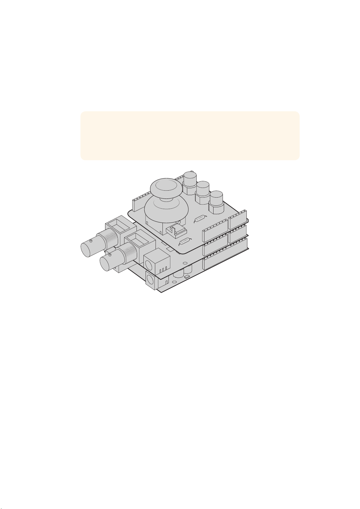
PTZ with Blackmagic 3G-SDI Shield for Arduino
Using the Blackmagic 3G-SDI Shield with an Arduino board, a joystick and a switch, you can
control a PTZ head via Blackmagic Micro Studio Camera 4K.
To connect Blackmagic Micro Studio Camera 4K to the Blackmagic Design 3G-SDI shield
1 Connect the Blackmagic Design 3G-SDI shield to an Arduino board.
2 Connect your custom shield to the Arduino board.
TIP This means the Blackmagic Design 3G-SDI shield will be the middle
component, sandwiched between the Arduino board and your custom Arduino
shield for PTZ control. The PTZ joystick and buttons can be built into your
custom Arduino shield, or connected to this shield externally.
The Blackmagic Design 3G-SDI shield is the middle component between
the Arduino board and your custom shield for PTZ control
3 Attach the SDI output connector from the shield to the SDI input on your
BlackmagicMicro Studio Camera 4K and set the camera as camera number 1.
The joystick is mapped as follows:
X axis adjusts the PTZ head’s pan.
Y axis adjusts the PTZ head’s tilt.
Pressing the joystick button tells the PTZ head to store the current X,
Ypositionin memory.
Pressing the switch recalls the stored position.
45PTZ Control over SDI
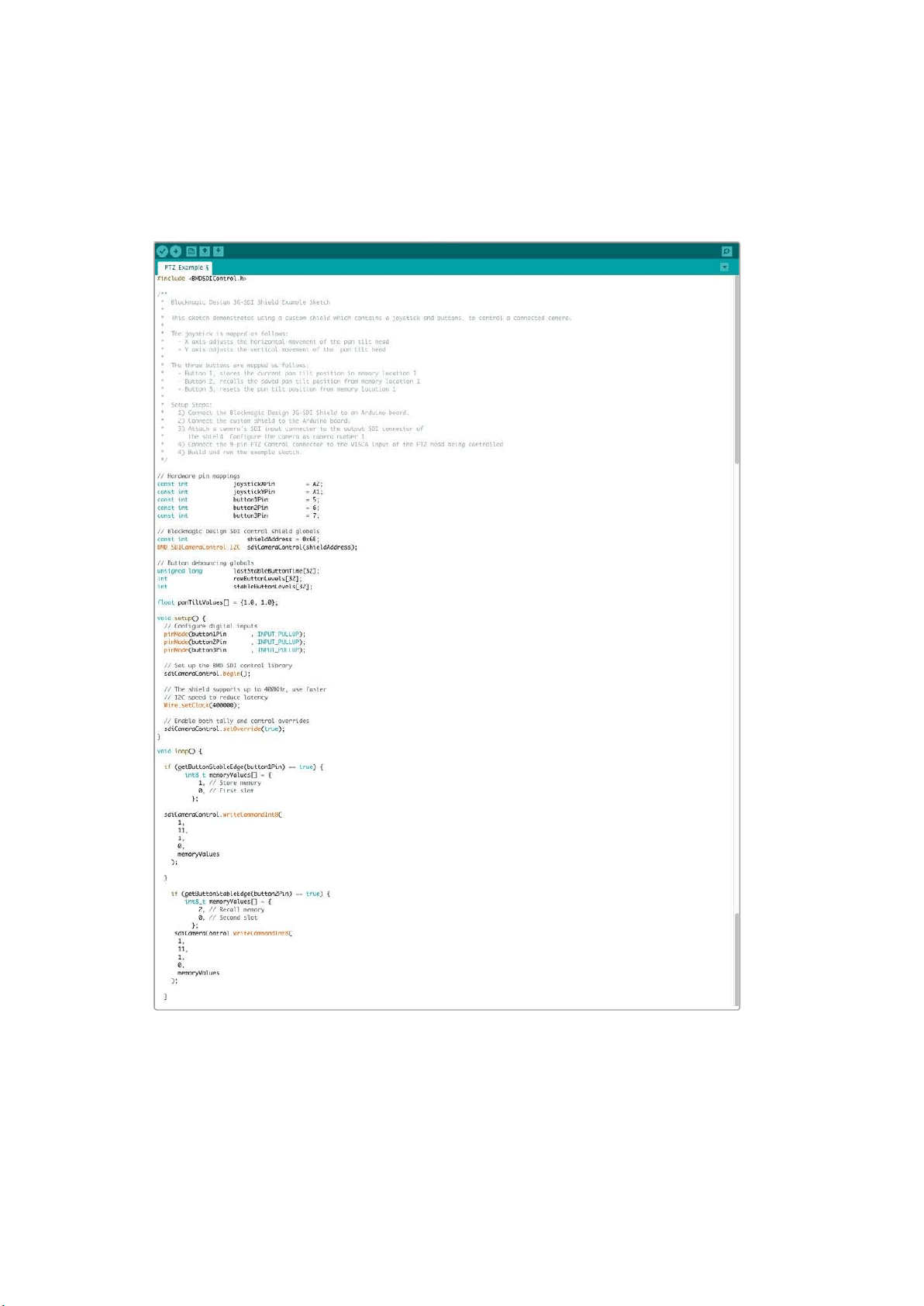
Controlling your Arduino
The following sketch demonstrates a simple example of using a joystick and button with
anArduino board and the Blackmagic 3G-SDI Shield for Arduino, to control a PTZ head via a
Blackmagic Micro Studio Camera 4K.
46PTZ Control over SDI
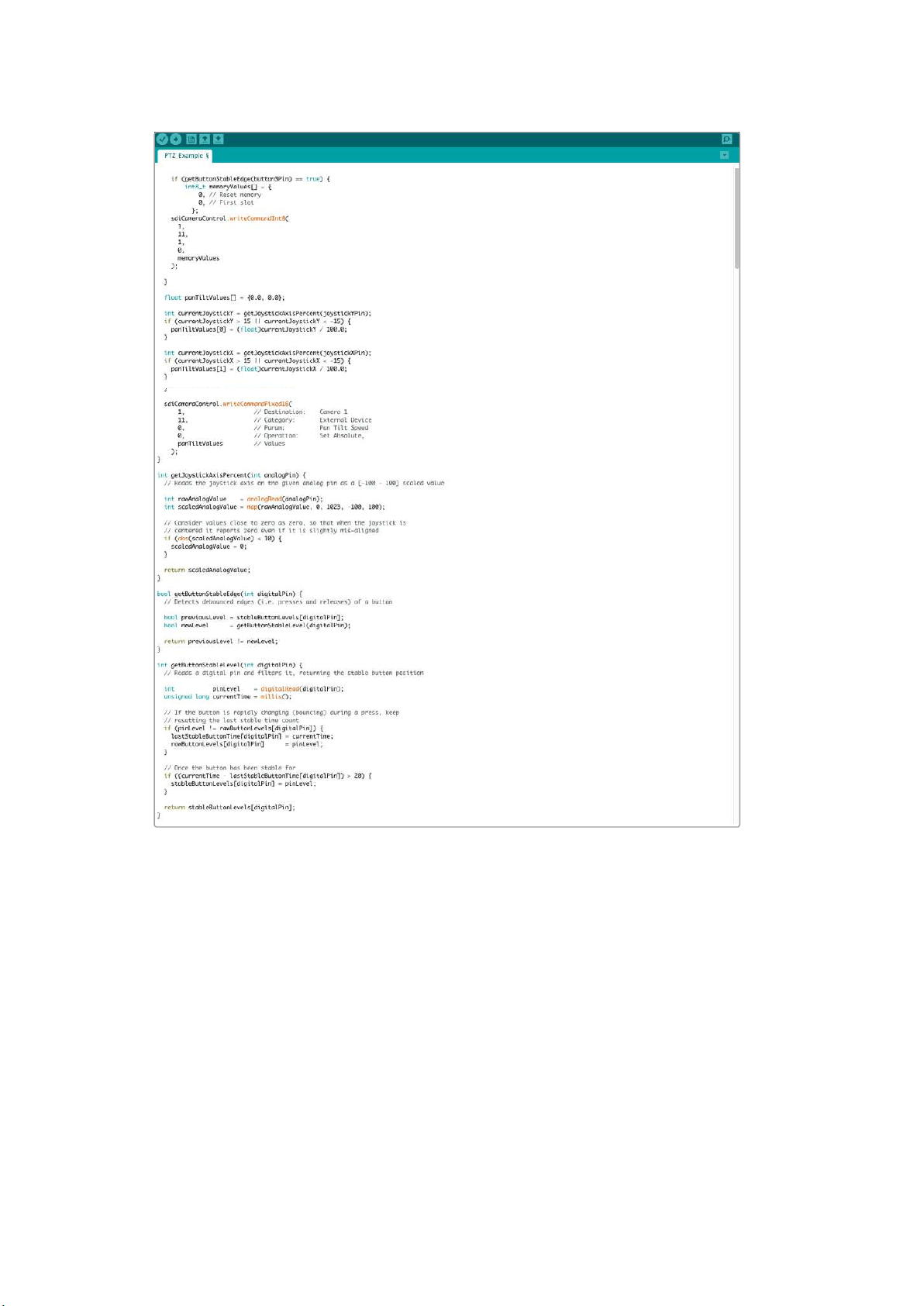
47PTZ Control over SDI

Developer Information
Blackmagic SDI Camera Control Protocol
Version 1.3
If you are a software developer you can use the SDI Camera Control Protocol to construct devices
that integrate with our products. Here at Blackmagic Design our approach is to open upour
protocols and we eagerly look forward to seeing what you come up with!
Overview
The Blackmagic SDI Camera Control Protocol is used by ATEM switchers, Blackmagic 3G-SDI
Shield for Arduino and the Blackmagic Camera Control app to provide Camera Control
functionality with supported Blackmagic Design cameras. Please refer to the ‘Understanding
Studio Camera Control’ chapter section of this manual, or the ATEM Switchers Manual
and SDKmanual for more information. These can be downloaded at
www.blackmagicdesign.com/support.
This document describes an extensible protocol for sending a uni directional stream of small
control messages embedded in the non-active picture region of a digital video stream. The
video stream containing the protocol stream may be broadcast to a number of devices. Device
addressing is used to allow the sender to specify which device each message is directed to.
Assumptions
Alignment and padding constraints are explicitly described in the protocol document. Bit fields
are packed from LSB first. Message groups, individual messages and command headers are
defined as, and can be assumed to be, 32 bit aligned.
Blanking Encoding
A message group is encoded into a SMPTE 291M packet with DID/SDID x51/x53 in the active
region of VANC line 16.
Message Grouping
Up to 32 messages may be concatenated and transmitted in one blanking packet up to a
maximum of 255 bytes payload. Under most circumstances, this should allow all messages to
be sent with a maximum of one frame latency.
If the transmitting device queues more bytes of message packets than can be sent in a single
frame, it should use heuristics to determine which packets to prioritize and send immediately.
Lower priority messages can be delayed to later frames, or dropped entirely as appropriate.
Abstract Message Packet Format
Every message packet consists of a three byte header followed by an optional variable length
data block. The maximum packet size is 64 bytes.
Destination device (uint8)
Device addresses are represented as an 8 bit unsigned integer. Individual
devices are numbered 0 through 254 with the value 255 reserved to indicate
a broadcast message to all devices.
Command length (uint8)
The command length is an 8 bit unsigned integer which specifies the length
of the included command data. The length does NOT include the length of
the header or any trailing padding bytes.
48Developer Information

Command id (uint8)
The command id is an 8 bit unsigned integer which indicates themessage
type being sent. Receiving devices should ignore any commands that they do
not understand. Commands 0 through 127 are reserved for commands that
apply to multiple types of devices. Commands 128 through 255 are
device specific.
Reserved (uint8)
This byte is reserved for alignment and expansion purposes. Itshould be
set to zero.
Command data (uint8[])
The command data may contain between 0 and 60 bytes of data. The format
of the data section is defined by the command itself.
Padding (uint8[])
Messages must be padded up to a 32 bit boundary with 0x0bytes.
Anypadding bytes are NOT included in the command length.
Receiving devices should use the destination device address and or the command identifier to
determine which messages to process. The receiver should use the command length to skip
irrelevant or unknown commands and should be careful to skip the implicit padding as well.
Defined Commands
Command 0 : change configuration
Category (uint8)
The category number specifies one of up to 256 configuration categories
available on the device.
Parameter (uint8)
The parameter number specifies one of 256 potential configuration
parameters available on the device. Parameters 0 through 127 are device
specific parameters. Parameters 128 though 255 are reserved for parameters
that apply to multiple types of devices.
Data type (uint8)
The data type specifies the type of the remaining data. Thepacket length is
used to determine the number of elements in the message. Each message
must contain an integral number of data elements.
Currently defined values are:
0: void / boolean
A void value is represented as a boolean array of length zero.
The data field is a 8 bit value with 0 meaning false and all other values
meaning true.
1: signed byte Data elements are signed bytes
2: signed 16bit integer Data elements are signed 16 bit values
3: signed 32bit integer Data elements are signed 32 bit values
4: signed 64bit integer Data elements are signed 64 bit values
5: UTF-8 string Data elements represent a UTF-8 string with no terminating character.
Data types 6 through 127 are reserved.
128: signed 5.11fixed point
Data elements are signed 16 bit integers representing a real number with
5bits for the integer component and 11 bits for the fractional component.
Thefixed point representation is equal to the real value multiplied by 2^11.
The representable range is from -16.0 to 15.9995
(15 + 2047/2048).
49Developer Information

Data types 129 through 255 are available for device specific purposes.
Operation type (uint8)
The operation type specifies what action to perform on the specified
parameter. Currently defined values are:
0: assign value
The supplied values are assigned to the specified parameter. Each element
will be clamped according to its valid range. A void parameter may only be
'assigned' an empty list of boolean type. This operation will trigger the action
associated with that parameter. A boolean value may be assigned the value
zero for false, and any other value for true.
1: offset / toggle value
Each value specifies signed offsets of the same type to be added to the
current parameter values. The resulting parameter value will be clamped
according to their valid range. It is not valid to apply an offset to a void value.
Applying any offset other than zero to a boolean value will invert that value.
Operation types 2 through 127 are reserved.
Operation types 128through 255 are available for device specific purposes.
Data (void)
The data field is 0 or more bytes as determined by the data type and number
of elements.
The category, parameter, data type and operation type partition a 24 bit operation space.
Group ID Parameter Type Index Minimum Maximum Interpretation
Lens
0.0 Focus fixed16 – 0 1 0.0 = near, 1.0 = far
0.1 Instantaneous autofocus void – – –
trigger
instantaneous autofocus
0.2 Aperture (f-stop) fixed16 – -1 16
Aperture Value (where
fnumber = sqrt(2^AV))
0.3 Aperture (normalised) fixed16 – 0 1 0.0 = smallest, 1.0 = largest
0.4 Aperture (ordinal) int16 – 0 n
Steps through available
aperture values from
minimum (0) to maximum (n)
0.5
Instantaneous
auto aperture
void – – –
trigger instantaneous
auto aperture
0.6 Optical image stabilisation boolean – – –
true = enabled, false
= disabled
0.7 Set absolute zoom (mm) int16 – 0 max
Move to specified focal
length in mm, from minimum
(0) to maximum (max)
0.8
Set absolute zoom
(normalised)
fixed16 – 0 1
Move to specified focal
length: 0.0 = wide, 1.0 = tele
0.9
Set continuous
zoom (speed)
fixed16 – -1 +1.0
Start/stop zooming at
specified rate: -1.0 = zoom
wider fast, 0.0 = stop,
+1 = zoom tele fast
50Developer Information

Group ID Parameter Type Index Minimum Maximum Interpretation
Video
1.0 Video mode int8
[0] = frame rate – – 24, 25, 30, 50, 60
[1] = M-rate – – 0 = regular, 1 = M-rate
[2] = dimensions – –
0 = NTSC,
1 = PAL,
2 = 720,
3 = 1080,
4 = 2k,
5 = 2kDCI,
6 = UHD
[3] = interlaced – –
0 = progressive, 1 =
interlaced
[4] = Color space – – 0 = YUV
1.1 Gain int8
1 16
1 = 100 ISO,
2 = 200 ISO,
4 = 400 ISO,
8 = 800 ISO,
16 = 1600 ISO
1.2 Manual White Balance
int16
[0] = color temp 2500 10000 Color temperature in K
int16
[1] = tint -50 50 tint
1.3 Set auto WB void
– – –
Calculate and set
autowhite balance
1.4 Restore auto WB void
– – –
Use latest auto white
balance setting
1.5 Exposure (us) int32
1 42000 time in us
1.6 Exposure (ordinal) int16
– 0 n
Steps through available
exposure valuesfrom
minimum (0) tomaximum (n)
1.7 Dynamic Range Mode int8 enum
– 0 1 0 = film, 1 = video,
1.8 Video sharpening level int8 enum
– 0 3
0 = off, 1 = low,
2= medium, 3 = high
1.9 Recording format int16
[0] = file
frame rate
– –
fps as integer
(eg 24, 25, 30, 50, 60, 120)
[1] = sensor
frame rate
– –
fps as integer, valid when
sensor-off-speed set (eg 24,
25, 30, 33, 48, 50, 60, 120),
no change will beperformed
if this value is set to 0
[2] = frame width – – in pixels
[3] = frame height – – in pixels
[4] = flags
– – [0] = file-M-rate
– –
[1] = sensor-M-rate, valid
whensensor-off-speed-set
– – [2] = sensor-off-speed
– – [3] = interlaced
– – [4] = windowed mode
1.10 Set auto exposure mode int8
– 0 4
0 = Manual Trigger,
1 = Iris,
2 = Shutter,
3 = Iris + Shutter,
4 = Shutter + Iris
1.11 Shutter angle int32
– 100 36000
Shutter angle in degrees,
multiplied by 100
1.12 Shutter speed int32
– 24 2000
Shutter speed value as a
fraction of 1, so 50 for 1/50th
of a second
1.13 Gain int8
– -128 127 Gain in decibel (dB)
1.14 ISO int32
– 0 2147483647 ISO value
51Developer Information

Group ID Parameter Type Index Minimum Maximum Interpretation
Audio
2.0 Mic level fixed16 – 0 1
0.0 = minimum,
1.0 = maximum
2.1 Headphone level fixed16 – 0 1
0.0 = minimum,
1.0 = maximum
2.2 Headphone program mix fixed16 – 0 1
0.0 = minimum,
1.0 = maximum
2.3 Speaker level fixed16 – 0 1
0.0 = minimum,
1.0 = maximum
2.4 Input type int8 – 0 2
0 = internal mic,
1 = line level input,
2 = low mic level input,
3 = high mic level input
2.5 Input levels fixed16
[0] ch0 0 1
0.0 = minimum,
1.0 = maximum
[1] ch1 0 1
0.0 = minimum,
1.0 = maximum
2.6 Phantom power boolean – – –
true = powered,
false = not powered
Output
3.0 Overlay enables
uint16
bit field
– – –
bit flags:
[0] = display status,
[1] = display frame guides
Some cameras don't allow
separate control of frame
guides and status overlays.
3.1
Frame guides style
(Camera 3.x)
int8
[0] = frame
guides style
0 8
0 = HDTV, 1 = 4:3, 2 = 2.4:1,
3 = 2.39:1, 4 = 2.35:1,
5 = 1.85:1, 6 = thirds
3.2
Frame guides opacity
(Camera 3.x)
fixed16
[1] = frame
guide opacity
0.1 1
0.0 = transparent,
1.0 = opaque
3.3
Overlays
(replaces .1 and .2
abovefrom
Cameras 4.0)
int8
[0] = frame
guides style
– –
0 = off, 1 = 2.4:1, 2 = 2.39:1,
3 = 2.35:1, 4 = 1.85:1, 5 = 16:9,
6 = 14:9, 7 = 4:3
[1] = frame
guide opacity
0 100
0 = transparent,
100 = opaque
[2] = safe area
percentage
0 100
percentage of full frame
used by safe area guide
(0 means off)
[3] = grid style – –
bit flags: [0] = display thirds,
[1] = display cross hairs,
[2] = display center dot
52Developer Information

Group ID Parameter Type Index Minimum Maximum Interpretation
Display
4.0 Brightness fixed16 – 0 1
0.0 = minimum,
1.0 = maximum
4.1 Overlay enables
int16
bit field
– – – 0x4 = zebra
– – – 0x8 = peaking
– – –
4.2 Zebra level fixed16 – 0 1
0.0 = minimum,
1.0 = maximum
4.3 Peaking level fixed16 – 0 1
0.0 = minimum,
1.0 = maximum
4.4
Color bars display
time (seconds)
int8 – 0 30
0 = disable bars, 1-30 =
enable bars with timeout (s)
4.5 Focus Assist int8
[0] = focus
assist method
– –
0 = Peak,
1 = Colored lines
[1] = focus
line color
– –
0 = Red,
1 = Green,
2 = Blue,
3 = White,
4 = Black
Tally
5.0 Tally brightness fixed16 – 0 1
Sets the tally front and tally
rear brightness to the
same level.
0.0 = minimum,
1.0 = maximum
5.1 Front tally brightness fixed16 – 0 1
Sets the tally front
brightness.
0.0 = minimum,
1.0 = maximum
5.2 Rear tally brightness fixed16 – 0 1
Sets the tally rear brightness.
0.0 = minimum,
1.0 = maximum
Tally rear brightness cannot
be turned off
Reference
6.0 Source int8 enum – 0 2
0 = internal,
1 = program,
2 = external
6.1 Offset int32 – – – +/- offset in pixels
Confi-
guration
7.0 Real Time Clock int32
[0] time _ _ BCD - HHMMSSFF (UCT)
[1] date _ _ BCD - YYYYMMDD
7.1 System language string _ _ _
ISO-639-1 two character
language code
7.2 Timezone int32 _ _ _ Minutes offset from UTC
7.3 Location int64
[0] latitude _ _
BCD - s0DDdddddddddddd
where s is the sign:
0 = north (+), 1 = south (-);
DD degrees, dddddddddddd
decimal degrees
[1] longitude _ _
BCD - sDDDdddddddddddd
where s is the sign: 0 = west
(-), 1 = east (+); DDD degrees,
dddddddddddd
decimal degrees
53Developer Information

Group ID Parameter Type Index Minimum Maximum Interpretation
Color
Correction
8.0 Lift Adjust fixed16
[0] red -2 2 default 0.0
[1] green -2 2 default 0.0
[2] blue -2 2 default 0.0
[3] luma -2 2 default 0.0
8.1 Gamma Adjust fixed16
[0] red -4 4 default 0.0
[1] green -4 4 default 0.0
[2] blue -4 4 default 0.0
[3] luma -4 4 default 0.0
8.2 Gain Adjust fixed16
[0] red 0 16 default 1.0
[1] green 0 16 default 1.0
[2] blue 0 16 default 1.0
[3] luma 0 16 default 1.0
8.3 Offset Adjust fixed16
[0] red -8 8 default 0.0
[1] green -8 8 default 0.0
[2] blue -8 8 default 0.0
[3] luma -8 8 default 0.0
8.4 Contrast Adjust fixed16
[0] pivot 0 1 default 0.5
[1] adj 0 2 default 1.0
8.5 Luma mix fixed16 – 0 1 default 1.0
8.6 Color Adjust fixed16
[0] hue -1 1 default 0.0
[1] sat 0 2 default 1.0
8.7 Correction Reset Default void – – – reset to defaults
54Developer Information

Group ID Parameter Type Index Minimum Maximum Interpretation
Media
10.0 Codec
int8
enum
[0] = basic codec – –
0 = RAW,
1 = DNxHD,
2 = ProRes,
3 = Blackmagic RAW
[1] = codec variant
– –
RAW:
0 = Uncompressed,
1 = lossy 3:1,
2 = lossy 4:1
– –
ProRes:
0 = HQ,
1 = 422,
2 = LT, 3 = Proxy,
4 = 444, 5 = 444XQ
– –
Blackmagic RAW:
0 = Q0,
1 = Q5,
2 = 3:1,
3 = 5:1,
4 = 8:1,
5 = 12:1
10.1 Transport mode int8
[0] = mode – –
0 = Preview,
1 = Play,
2 = Record
[1] = speed – –
-ve = multiple speeds
backwards,
0 = pause,
+ve = multiple
speeds forwards
[2] = flags – –
1<<0 = loop,
1<<1 = play all,
1<<5 = disk1 active,
1<<6 = disk2 active,
1<<7 = time-lapse recording
[3] = active
storage medium
– –
0 = CFast card,
1 = SD
PTZ
Control
11.0
Pan/Tilt Velocity fixed 16
[0] = pan velocity -1.0 1.0
-1.0 = full speed left,
1.0 = full speed right
[1] = tilt velocity -1.0 1.0
-1.0 = full speed down,
1.0 = full speed up
11.1 Memory Preset
int8 enum
[0] =
preset command
– –
0 = reset,
1 = store location,
2 = recall location
int8
[1] =
preset slot
0 5 –
55Developer Information
Example Protocol Packets
Operation
Packet
Length Byte
0 1 2 3 4 5 6 7 8 9 10 11 12 13 14 15
header command data
destination
length
command
reserved
category
parameter
type
operation
trigger instantaneous
auto focus on camera 4
8 4 4 0 0 0 1 0 0
turn on OIS on all cameras 12 255 5 0 0 0 6 0 0 1 0 0 0
set exposure to 10 ms on
camera 4 (10 ms = 10000
us = 0x00002710)
12 4 8 0 0 1 5 3 0 0x10 0x27 0x00 0x00
add 15% to zebra level
(15 % = 0.15 f = 0x0133 fp)
12 4 6 0 0 4 2 128 1 0x33 0x01 0 0
select 1080p 23.98 mode on
all cameras
16 255 9 0 0 1 0 1 0 24 1 3 0 0 0 0 0
subtract 0.3 from gamma
adjust for green & blue
(-0.3 ~= 0xfd9a fp)
16 4 12 0 0 8 1 128 1 0 0 0x9a 0xfd 0x9a 0xfd 0 0
all operations combined 76 4 4 0 0 0 1 0 0 255 5 0 0 0 6 0 0
1 0 0 0 4 8 0 0 1 5 3 0 0x10 0x27 0x00 0x00
4 6 0 0 4 2 128 1 0x33 0x01 0 0 255 9 0 0
1 0 1 0 24 1 3 0 0 0 0 0 4 12 0 0
8 1 128 1 0 0 0x9a 0xfd 0x9a 0xfd 0 0
56Developer Information

Blackmagic Embedded TallyControl Protocol
Version 1.0 (30/04/14)
This section is for third party developers or anybody who may wish to add support for the
Blackmagic Embedded Tally Control Protocol to their products or system. It describes the
protocol for sending tally information embedded in the non-active picture region of a digital
video stream.
Data Flow
A master device such as a broadcast switcher embeds tally information into its program feed
which is broadcast to a number of slave devices such as cameras or camera controllers. The
output from the slave devices is typically fed back to the master device, but may also be sent to
a video monitor.
The primary flow of tally information is from the master device to the slaves. Each slave device
may use its device id to extract and display the relevant tally information.
Slave devices pass through the tally packet on their output and update the monitor tally status,
so that monitor devices connected to that individual output may display tally status without
knowledge of the device id they are monitoring.
Assumptions
Any data alignment / padding is explicit in the protocol. Bit fields are packed from LSB first.
Blanking Encoding
One tally control packet may be sent per video frame. Packets are encoded as a SMPTE 291M
packet with DID/SDID x51/x52 in the active region of VANC line 15. A tally control packet may
contain up to 256 bytes of tally information.
Packet Format
Each tally status consists of 4 bits of information:
uint4
bit 0: program tally status (0=off, 1=on)
bit 1: preview tally status (0=off, 1=on)
bit 2-3: reserved (0x0)
The first byte of the tally packet contains the monitor device tally status and a version number.
Subsequent bytes of the tally packet contain tally status for pairs of slave devices. The master
device sends tally status for the number of devices configured/supported, up to a
maximum of 510.
struct tally
uint8
bit 0: monitor device program tally status (0=off, 1=on)
bit 1: monitor device preview tally status (0=off, 1=on)
bit 2-3: reserved (0b00)
bit 4-7: protocol version (0b0000)
uint8[0]
bit 0: slave device 1 program tally status (0=off, 1=on)
bit 1: slave device 1 device preview tally status (0=off, 1=on)
bit 2-3: reserved (0b00)
bit 4: slave device 2 program tally status (0=off, 1=on)
bit 5: slave device 2 preview tally status (0=off, 1=on)
bit 6-7: reserved (0b00)
57Developer Information
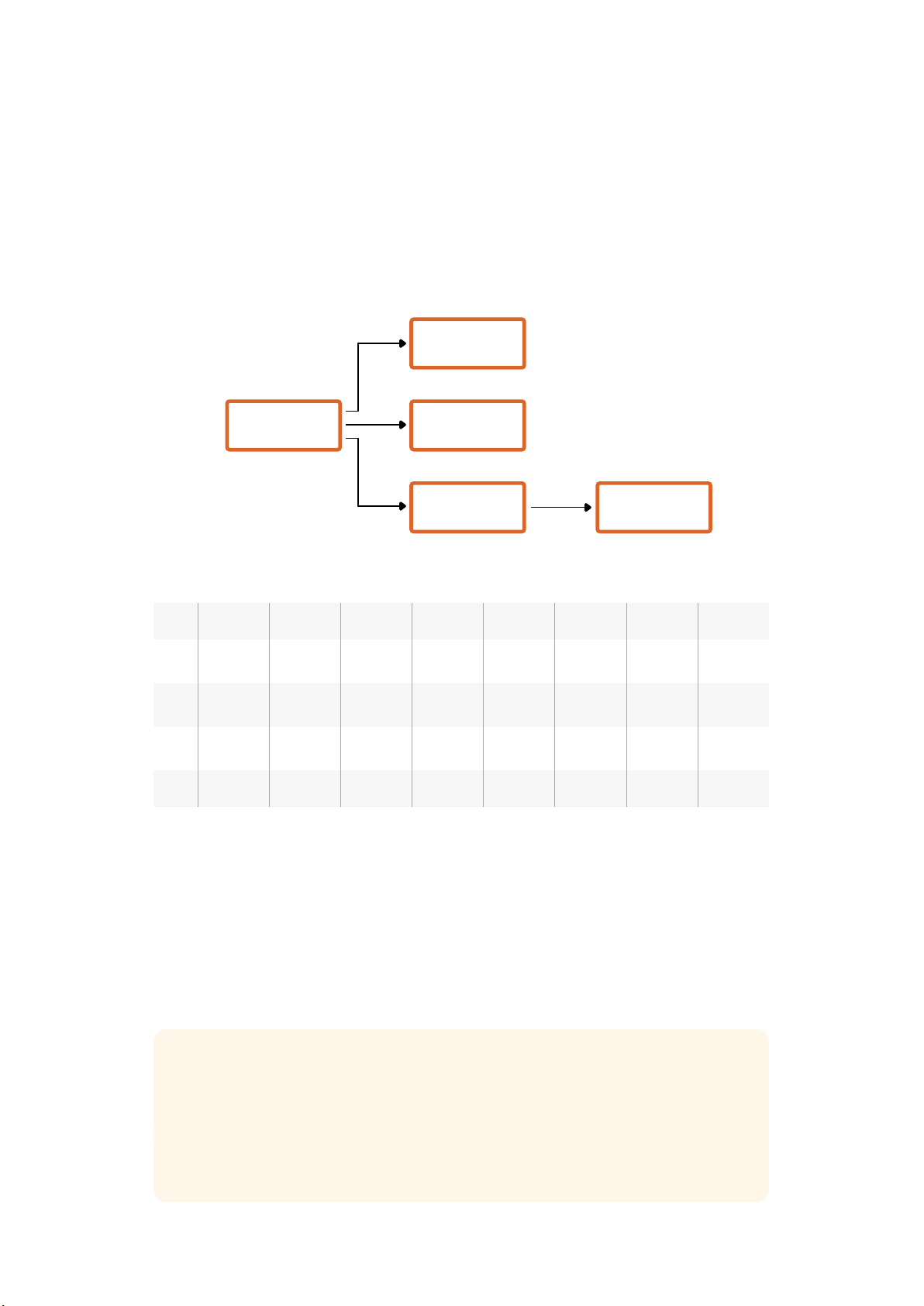
uint8[1]
bit 0: slave device 3 program tally status (0=off, 1=on)
bit 1: slave device 3 device preview tally status (0=off, 1=on)
bit 2-3: reserved (0b00)
bit 4: slave device 4 program tally status (0=off, 1=on)
bit 5: slave device 4 preview tally status (0=off, 1=on)
bit 6-7: reserved (0b00)
. . .
Byte 7 MSB 6 5 4 3 2 1 0 LSB
0
Version
(0b0)
Version
(0b0)
Version
(0b0)
Version
(0b0)
Reserved
(0b0)
Reserved
(0b0)
Monitor
Preview
Monitor
Program
1
Reserved
(0b0)
Reserved
(0b0)
Slave 1
Preview
Slave 1
Program
Reserved
(0b0)
Reserved
(0b0)
Slave 0
Preview
Slave 0
Program
2
Reserved
(0b0)
Reserved
(0b0)
Slave 3
Preview
Slave 3
Program
Reserved
(0b0)
Reserved
(0b0)
Slave 2
Preview
Slave 2
Program
3 ...
RAW SDI Output
If you would like to perform your own debayering of the image data from Blackmagic Micro Studio
Camera 4K, you can use the ‘RAW’ mode to output bayered sensor data over the SDI output.
This mode packs raw data into the pixels of a regular UltraHD 422 frame size, to enable
transmission through a standard SDI output.
The data can be recorded as an uncompressed QuickTime movie using a disk recorder capable
of uncompressed 10-bit recording.
TIP Camera raw media formats are so named because they capture raw color space
data directly from the sensor. Raw image data cannot be displayed visually, and must
be debayered or demosaiced to convert the original raw data into image data that can
then be used in an image processing pipeline like DaVinci Resolve.
Note that Blackmagic DaVinci Resolve does not support the debayering of raw data
from Blackmagic Micro Studio Camera 4K.
Master Device
Monitor Device
Slave Device
(2)
Slave Device
(3)
Slave Device
(1)
58Developer Information
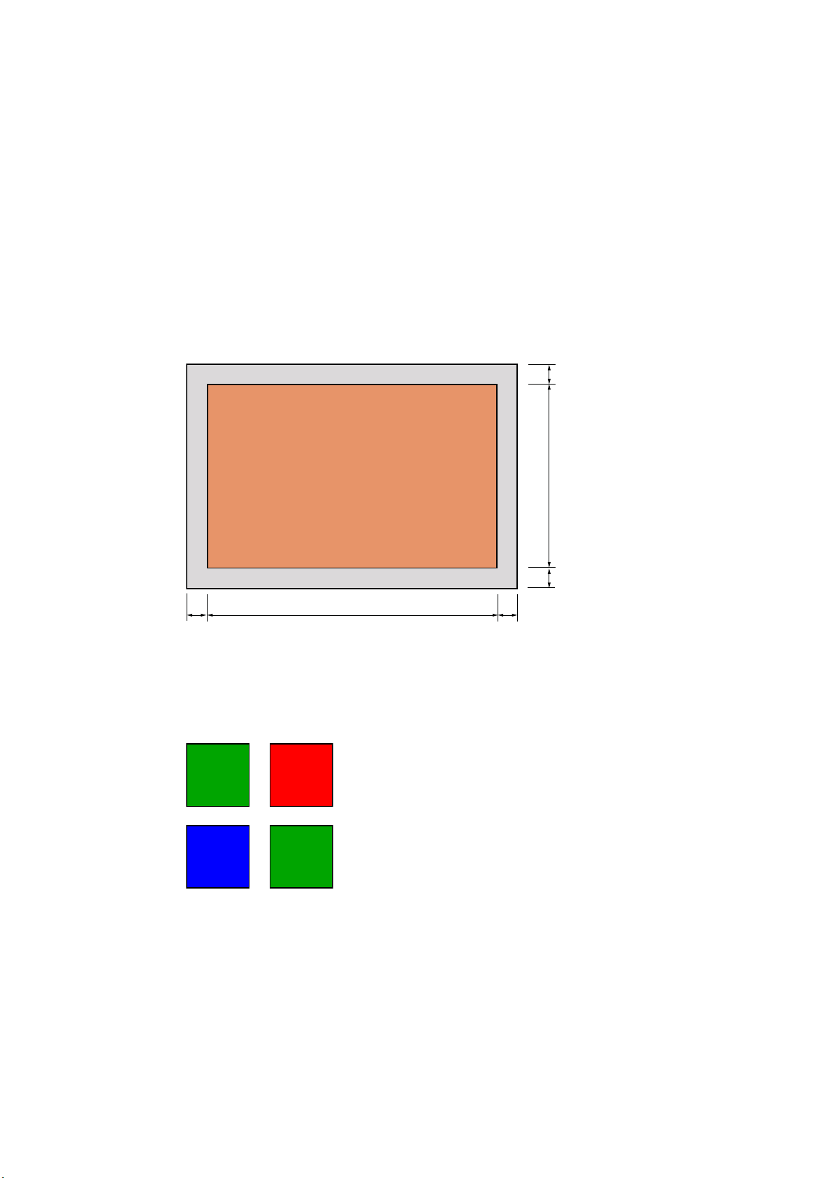
Enabling RAW mode:
1 Press menu and select the ‘setup’ page.
2 Navigate to ‘RAW SDI Output’ and select ‘on’.
Resolution and Bit Depth
The resolution of the RAW frame is 3872 pixels x 2192 lines, which includes a border that
surrounds the image data. Most users discard this border after debayering, as it can contain
image artifacts on the outer edges.
The RAW data at pixel number 16 inside the horizontal and vertical corners will therefore
correspond with the corner of the Ultra HD frame when the camera is outputting 3840 x 2160 in
the non RAW mode. The bit depth of each pixel will be 12 bits.
Bayer Alignment
The bayer pattern of the RAW frame provides information required for debayering the raw data
output by Blackmagic Micro Studio Camera 4K. The bayer alignment of the RAW frame is GRBG
or green, red, blue, green.
Packing
Packing describes the way in which the raw data is packed or arranged. It is important to
understand the way that the data has been packed so that it can be unpacked correctly.
TheRAW frame will be packed into the active picture area of a standard UHD 422 SDI frame,
using the following repeated packing scheme:
RAW image pixels
RAW data border
16
2160
16
16384016
0,0 1,0
0,1 1,1
59Developer Information

9 8 7 6 5 4 3 2 1 0
SDI(0,0) CB
0 1 RAW (0,0)[7:0]
SDI(0,0)Y
0 1 RAW(1,0)[3:0] RAW(0,0)[11:8]
SDI(1,0) CR
0 1 RAW(1,0)[11:4]
SDI(1,0) Y
0 1 RAW (2,0)[7:0]
SDI(2,0) CB
0 1 RAW(3,0)[3:0] RAW(2,0)[11:8]
SDI(2,0) Y
0 1 RAW(3,0)[11:4]
Horizontal and vertical blanking will be unchanged from regular SDI output mode.
As shown above, four RAW pixels will be packed into three SDI pixels, so each Ultra HD line will
contain 3840 x 4/3 = 5120 RAW pixels and the entire RAW frame will be carried in the first 1658
lines of the 2160 active SDI lines. The remainder of the pixels in the SDI frame will be set to
0x100 for both Y and C.
The RAW SDI frame should be captured as uncompressed 422 data and unpacked according to
the table above.
Recording the RAW signal
The data can be recorded as an uncompressed 10-bit YUV recording using a 6G-SDI capable
product, such as one of the following:
UltraStudio 4K
UltraStudio 4K Extreme 3
DeckLink 8K Pro
DeckLink 4K Extreme 12G
DeckLink Studio 4K
DeckLink SDI 4K
DeckLink Mini Recorder 4K
Unpacking the RAW data:
Once you have a QuickTime recording of the RAW data, you will need to unpack the signal to
perform your own debayering of the image data from the sensor.
60Developer Information

Help
Getting Help
The fastest way to obtain help is to go to the Blackmagic Design online support pages and
check the latest support material available for your camera.
Blackmagic Design Online Support Pages
The latest manual, software and support notes can be found at the Blackmagic Design support
centre at www.blackmagicdesign.com/support.
Contacting Blackmagic Design Support
If you can’t find the help you need in our support material, please use the “Send us an email”
button on the support page for your camera to email a support request. Alternatively, click on
the “Find your local support team” button on the support page and call your nearest
Blackmagic Design support office.
Checking the Software Version Currently Installed
To check which version of Blackmagic Camera Setup software is installed on your computer,
open the About Blackmagic Camera Setup window.
On Mac OS X, open Blackmagic Camera Setup from the Applications folder.
Select About Blackmagic Camera Setup from the application menu to reveal the
version number.
On Windows, open Blackmagic Camera Setup from your Start menu or Start Screen.
Click on the Help menu and select About Blackmagic Camera Setup to reveal the
version number.
How to Get the Latest Software Updates
After checking the version of Blackmagic Camera Setup software installed on your computer,
please visit the Blackmagic Support Center at www.blackmagicdesign.com/support to check for
the latest updates. While it is usually a good idea to run the latest updates, it is wise to avoid
updating any software if you are in the middle of an important project.
Battery Replacement
The Studio Camera’s built in battery is not user-serviceable. Should the battery require
replacement, you will need to send it to your nearest Blackmagic Design service center for
replacement. If the camera is outside of its warranty period, the battery replacement will incur
a small service fee for the cost of the battery, labor and return of the camera to you. Please
contact Blackmagic Design Support to find out details of where to send your camera, how to
package it safely and how much the replacement will cost in your country.
NOTE Blackmagic Studio Camera 2 and Blackmagic Studio Camera 4K 2 do not have
internal batteries.
61Help

Warranty
12 Month Limited Warranty
Blackmagic Design warrants that this product will be free from defects in materials and workmanship
for a period of 12 months from the date of purchase. If a product proves to be defective during this
warranty period, Blackmagic Design, at its option, either will repair the defective product without
charge for parts and labor, or will provide a replacement in exchange for the defective product.
In order to obtain service under this warranty, you the Customer, must notify Blackmagic Design
of the defect before the expiration of the warranty period and make suitable arrangements for the
performance of service. The Customer shall be responsible for packaging and shipping the
defective product to a designated service center nominated by Blackmagic Design, with shipping
charges pre paid. Customer shall be responsible for paying all shipping charges, insurance, duties,
taxes, and any other charges for products returned to us for any reason.
This warranty shall not apply to any defect, failure or damage caused by improper use or improper
or inadequate maintenance and care. Blackmagic Design shall not be obligated to furnish service
under this warranty: a) to repair damage resulting from attempts by personnel other than
Blackmagic Design representatives to install, repair or service the product, b) to repair damage
resulting from improper use or connection to incompatible equipment, c) to repair any damage or
malfunction caused by the use of non Blackmagic Design parts or supplies, or d) to service a
product that has been modified or integrated with other products when the effect of such a
modification or integration increases the time or difficulty of servicing the product. THIS WARRANTY
IS GIVEN BY BLACKMAGIC DESIGN IN LIEU OF ANY OTHER WARRANTIES, EXPRESS OR IMPLIED.
BLACKMAGIC DESIGN AND ITS VENDORS DISCLAIM ANY IMPLIED WARRANTIES OF
MERCHANTABILITY OR FITNESS FOR A PARTICULAR PURPOSE. BLACKMAGIC DESIGN’S
RESPONSIBILITY TO REPAIR OR REPLACE DEFECTIVE PRODUCTS IS THE WHOLE AND EXCLUSIVE
REMEDY PROVIDED TO THE CUSTOMER FOR ANY INDIRECT, SPECIAL, INCIDENTAL OR
CONSEQUENTIAL DAMAGES IRRESPECTIVE OF WHETHER BLACKMAGIC DESIGN OR THE
VENDOR HAS ADVANCE NOTICE OF THE POSSIBILITY OF SUCH DAMAGES. BLACKMAGIC
DESIGN IS NOT LIABLE FOR ANY ILLEGAL USE OF EQUIPMENT BY CUSTOMER. BLACKMAGIC
IS NOT LIABLE FOR ANY DAMAGES RESULTING FROM USE OF THIS PRODUCT. USER OPERATES
THIS PRODUCT AT OWN RISK.
© Copyright 2018 Blackmagic Design. All rights reserved. ‘Blackmagic Design’, ‘DeckLink’, ‘HDLink’, ‘Workgroup Videohub’,
‘Multibridge Pro’, ‘Multibridge Extreme’, ‘Intensity’ and ‘Leading the creative video revolution’ are registered trademarks in the
US and other countries. All other company and product names may be trade marks of their respective companies with which
they are associated.
62Warranty