Loading ...
Loading ...
Loading ...
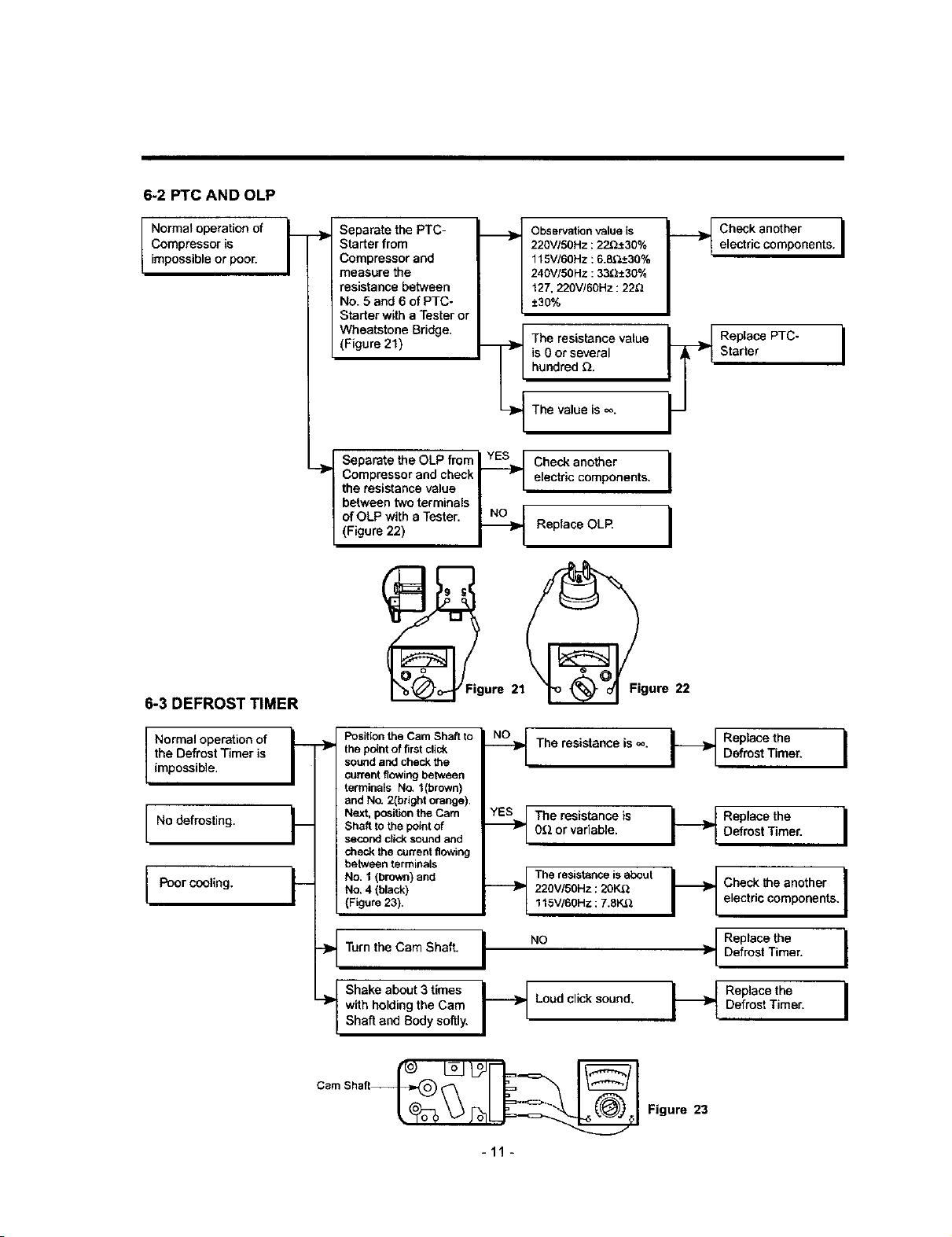
6-2 PTC AND OLP
11
Normal operation of
Compressor is -_
/
impossible or poor.
Separate the PTC-
Starter from
Compressor and
measure the
resistance between
No. 5 and 6 of PTC-
Starter with a Tester or
Wheatstone Bridge.
(Figure 21)
._}1_ Observation value is _ Check another |
220VISOHz: 22_±30% electric components, I
115V/60Hz : 6.8__+30%
=
240VI50 HZ: 33_±30%
127.220V!60Hz : 22_
±30%
is 0 or several Starter I
hundred _.
=
The value is _o.
I Separate the OLP freml YES_[ Check another
Compressor and check I Vl electric components. I
-]P
the resistance value I I
!
between two terminals J r
of OLP with a Tester. _ I
(Figure 22) _ Replace OLR
6-3 DEFROST TIMER
_/Fl'igure 21_igure 22
Normal operation of
the Defrost Timer is
impossible.
No defrosting.
Poor cooling.
Position the Cam Shaft to
the point of first click
sound and check the
current flowing between
terminals No. t(brown)
and No. 2(boght orange).
I__ Next, posi0on the Cam
Shaft to the point of
second click sound and
check the current flowing
between terminals
__ No. 1 (brown) and
No. 4 (black)
(Figure 23).
-_ Turn the Cam Shaft.
f Shake about 3 times
-_ with holding the Cam
Shaft and Body softly.
_--_ The resistanceis _. t_ DRePlroa_tethmeer. I
._The resistance is
0_2or variable.
The resistanceis about
220V/50Hz :2OK.Q
115V/60Hz :7.8K&_
I "°
-_ Loud click sound,
I__ Replace the
Defrost Timer. I
_ Check the another ]
electric components. I
Replace the
Defrost Timer.
Replace the I
Defrost Timer.
-11 -
Figure 23
Loading ...
Loading ...
Loading ...