Loading ...
Loading ...
Loading ...
4
2. Installation
2.1 Inspection
Inspect the exterior of the unit for shipping damage by ensuring that there is no damage to the door, door latches, door hinges,
damper, duct collars, cabinet, etc. Inspect the interior of the unit for damage by ensuring that the fan motors and housings, heat or
energy recovery cores, insulation, dampers, actuators and drain pans are all intact.
If transportation damage is found, le a claim immediately with the transportation agency. Remove all packaging, tape, etc. from the
cabinet.
2.2 Mounting Location Requirements
When determining an installation location, the unit must be mounted in a heated area to prevent condensate drain lines from freezing.
The mounting location should be away from occupied areas to provide quiet operation. The area should also be easily accessible for
maintenance.
NOTE: These units have minimum clearance requirements when mounting. See Appendix B for speci c clearance requirements.
Mounting options must allow 12” (305 mm) clearance in front of control cover for access.
A mounting location close to an exterior partition will minimize the length of insulated duct. The unit should be close to a drain and
120volt, 60 Hz power supply. The unit should be mounted away from hot chimneys, electrical panels and other hazards.
2.3 Mounting Options
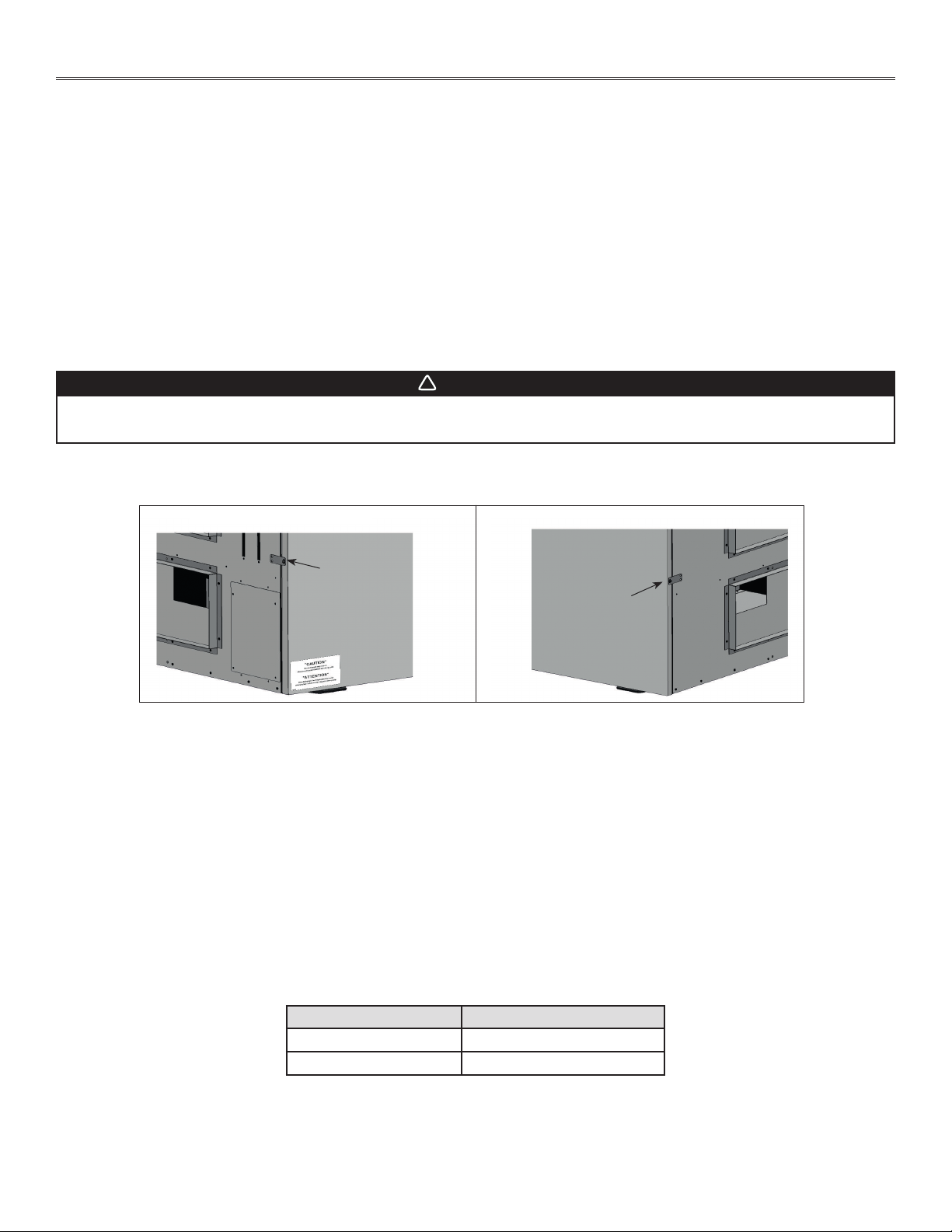
NOTE: Remove and discard the metal plate screwed on the unit to prevent the door from opening during transport.
There are several options for hanging or oor mounting the unit.
NOTE: In all cases, the unit must be level. Consult local building code for restrictions in your area regarding installation.
Hang the unit with the reinforced rubber straps provided as shown in Appendix A. Check with local building codes regarding the use
of rubber straps in commercial buildings. Attach the straps to the unit with two no. 8 screws provided. Then attach the other end of the
strap to the ceiling joists, trusses, custom frame, etc.
The unit can also be hung with 3/8” (10 mm) threaded rod and U channels or angles (not supplied) as shown in Appendix A.
When installing the unit, keep in mind that access to the control panel may be required. Supply and exhaust ducts to outdoors may have
1” to 2” (25 mm to 51 mm) of insulation on them. Rubber vibration isolation may be required and is recommended for quiet operation.
The unit can also be mounted on a metal or wooden curb (not supplied) bolted to the oor as shown in Appendix A. Space must be left under
the unit to allow connection of drain lines. A gradual slope is required for the condensate water to drain by gravity (minimum 1/4”/foot)
(6 mm/305 mm). If this is not possible, a pump should be used. If attachment of the unit to the curb is required, ensure that screws, bolts
and mounting hardware do not interfere with moving parts or that the integrity of the cabinet insulation is not affected.
2.4 Ductwork
The supply and exhaust duct connections on the unit are as follows:
UNIT DUCT SIZE
B6LC 14” x 8” (356 mm x 203 mm)
B12LC 20” x 8” (508 mm x 203 mm)
NOTE: Duct sizes are for connection purposes only. Ducts should be sized to keep noise and pressure drop to a minimum.
The supply and exhaust ducts connected to outdoors, as well as any ducts passing through an unconditioned space, must have a minimum
insulation value of R5. In addition, a continuous integral vapor barrier over the duct insulation must be used.
WARNING
!
To reduce the risk of injury caused by sharp edges and/or moving parts, it is recommended to wear safety glasses
and gloves while performing these instructions.
VD0523
Metal plate
Metal plate
Left side, standard door
Right side, reversed door
Loading ...
Loading ...
Loading ...