
_truction anu
®
rE lo..L"
3/4 Horsepower (continuous duty)
1-1/2 Horsepower (maximum developed)
16-Speed, Step Punmey
215 - 2720 R.P.M. Drill Speed Range
1iLL P SS
Ji
Model No.
152.229010
C S
FOR YOUR OWN SAFETY; Read
and foUlow all of the Safety and
Operating Instructions before
Operating this DdH Press.
Customer Helpline
1-800-897-7709
PRease have your Model No.
and SedaR No. availabUe.
Sears, Roebuck and Co., Hoffman Estates, JL 60179 U.S.A.
Part No. OR93513 EspaSoL pg, 31

SECTmON PAGE
Warranty..........................................................................................................................................................................2
ProductSpecifications...................................................................................................................................................3
Safetymnstructions.........................................................................................................................................................4
Guidelinesfor extension cords ..................................................................................................................................... 5
Grounding mnstructions .................................................................................................................................................. 6
Specific Safety mnstructions .......................................................................................................................................... 7
Accessories and Attachments ...................................................................................................................................... 8
Know Your Machine ....................................................................................................................................................... 9
Carton Contents ........................................................................................................................................................... 10
AssembJy mnstructions ................................................................................................................................................. 12
Operations and Adjustment ........................................................................................................................................ 17
Maintenance .................................................................................................................................................................. 26
Troubleshooting Guide ................................................................................................................................................ 27
Part List ......................................................................................................................................................................... 28
EspaSol .......................................................................................................................................................................... 3!
Service Information ........................................................................................................................................ Back Page
ONE-YEAR FULL WARRANTY ON CRAFTSMAN TOOL
if this Craftsman tool fails due to a defect in material or workmanship within one year from the date of purchase,
CALL 1-800-4-MY-HOME _) TO ARRANGE FOR FREE REPAIR,
This warranty applies only while this tool is in the United States,
This warranty gives you specific legal rights, and you may also have other rights, which vary from state to state,
Sears, Roebuck and Co,, Dept 817WA, Hoffman Estates, IL 60179

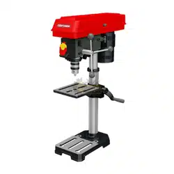
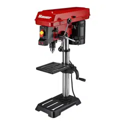
17°in. Drill Press with Laser°Trac TM
Motor Specifications:
Motor type induction
Continuous duty HP 3/4
Maximum developedHP 1=1/2
Amps 10/5
Volts 120/240
Phase Single
Hertz 60
R,P,M, 1725 (no load)
Product Specifications:
Belt Type
Pulley Type
Number of Speeds
Drill Speeds
Spindle Taper
Chuck Taper
Chuck Type
Chuck capacity
Chuck to Table dimension
Min,
Poly=V
Step
Motor slide
16
215, 310, 340, 450, 490,
51O, 600, 675, 735,750,
1200, 1380, 1500, 1850,
2035, 2720
#2 Morse Taper
Jacobs 3
Keyless
1/32" =5/8" (1 =16mm)
O _
Chuck to Table dimension
Max, 23-1/2"
Chuck to Base dimension 43ol/2"
Quill Diameter 1=7/8" (47mm)
Quill Travel 4=7/8"
Quill Lock Yes
Handle Operation
Motor Control
Table Size
Table Tilt
Table Movement
Table Material
Depth Stop
Depth Stop Type
Depth Scab
Column Diameter
Base Work Area
depth
Depth of Throat
Height
Width
Depth
Weight
360 degree rotation
Industrial push button
with OFF paddle
14" wide x 14" depth
Yes
Rack and pinion
Cast iron
Yes
Quick Set
Yes
3-1/8" (80ram)
10=1/4" wide x 8=1/4"
8=1/2"
68=1/2"
12=3/4"
28-1/2"
198 pounds
Convenience:
Light Yes
Laser Yes
To avoid electrical shock to yourself and damage to the
drill press, use proper circuit protection, Do not expose
to rain, or use in a damp environment,
The drill press is factory wired for 120V, 60 Hz, opera-
tion, Connect to a 120V, 15 amp branch circuit and use
a 15 amp time delay fuse or circuit breaker, The electri-
cal circuit cannot have any wire size less than #14, To
avoid shock or fire, replace power cord immediately if it
is damaged in any way,

GENERAL SAFETY iNSTRUCTiONS
Operating a drill press can be dangerous if safety and
common sense are ignored, The operator must be
familiar with the operation of the tool, Read this manual
to understand this drill press, DO NOT operate this drill
press if you do not fully understand the limitations of
this tool, DO NOT modify this drill press in any way,
REMEMBER: Your personal safety is your responsibility,
BEFORE USUNG THE DF_ULL PRESS
To avoid serious injury and damage to the tool, read
and follow all of the Safety and Operating instructions
before operating the drill press,
1, READ the entire instruction Manual, LEARN how to
use the tool for its intended applications,
2, ALWAYS WEAR EYE PROTECTION, Any power
tool can throw debris into the eyes during opera-
tions, which could cause severe and permanent
eye damage, Everyday eyeglasses are NOT safety
glasses, ALWAYS wear Safety Goggles (that
comply with ANSi standard Z87,1) when operating
power tools, Safety Goggles are available at Sears
Retail Stores,
3, ALWAYS WEAR HEARING PROTECTION, Plain
cotton is not an acceptable protective device,
Hearing equipment should comply with ANSi
$3,19 Standards,
4, ALWAYS WEAR A DUST MASK TO PREVENT
INHALING DANGEROUS DUST OR AIRBORNE
PARTICLES, including wood dust, crystalline silica
dust and asbestos dust, Direct particles away from
face and body, Always operate tool in well ventilat-
ed area and provide for proper dust removal, Use
dust collection system whenever possible,
Exposure to the dust may cause serious and per-
manent respiratory or other injury, including silicosis
(a serious lung disease), cancer, and death, Avoid
breathing the dust, and avoid prolonged contact
with dust, Allowing dust to get into your mouth or
eyes, or lay on your skin may promote absorption of
harmful material, Always use properly fitting
NIOSH/OBHA approved respiratory protection
appropriate for the dust exposure, and wash
exposed areas with soap and water,
5, ALWAYS keep the work area clean, well lit, and
organized, DO NOT work in an environment with
floor surfaces that are slippery from debris, grease,
and wax,
6, ALWAYS unplug the tool from the electrical recep-
tacle when making adjustments, changing parts or
performing any maintenance,
7,
8,
9,
10,
11,
12,
13,
14,
15,
16,
17,
18,
19,
AVOID ACCIDENTAL STARTING, Make sure that
the power switch is in the "OFF" position before
plugging in the power cord to the electrical
receptacle,
AVOID A DANGEROUS WORKING ENVIRON-
MENT. DO NOT Use electrical tools in a damp
environment or expose them to rain.
CHILDPROOF THE WORKSHOP AREA by remov-
ing switch keys, unplugging tools from the electrical
receptacles, and using padlocks,
DO NOT use electrical tools in the presence of
flammable liquids or gasses,
DO NOT FORCE THE TOOL to perform an opera-
tion for which it was not designed, it wiii do a safer
and higher quality job by only performing operations
for which the tool was intended,
DO NOT stand on a tool, Serious injury could result
if the tool tips over or you accidentally contact the
tool,
DO NOT store anything above or near the tool
where anyone might try to stand on the tool to
reach it,
DO NOT operate tool if under the influence of drugs
or alcohol,
EACH AND EVERY TIME, CHECK FOR DAMAGED
PARTS PRIOR TO USING THE TOOL. Carefully
check all guards to see that they operate properly,
are not damaged, and perform their intended func-
tions, Check for alignment, binding or breaking of
moving parts, A guard or other part that is damaged
should be immediately repaired or replaced,
GROUND ALL TOOLS, if the tool is supplied with a
3-prong plug, it must be plugged into a 3-contact
electrical receptacle, The 3rd prong is used to
ground the tool and provide protection against
accidental electric shock, DO NOT remove the 3rd
prong, See Grounding instructions,
KEEP VISITORS AND CHILDREN AWAY from the
drill press, DO NOT permit people to be in the
immediate work area, especially when the electrical
tool is operating,
KEEP PROTECTIVE GUARDS IN PLACE AND IN
WORKING ORDER,
MAINTAIN YOUR BALANCE. DO NOT extend
yourself over the tool. Wear oil resistant rubber-
soled shoes. Keep floor clear of debris, grease, and
wax,
20, MAINTAIN TOOLS WITH CARE, Always keep tools
clean and in good working order, Keep all blades
and tool bits sharp,
21, NEVER LEAVE A RUNNING TOOL UNATTENDED,
Turn the power switch to the OFF position, DO
NOT leave the tool until it has come to a complete
stop,
22, REMOVE ALL MAINTENANCE TOOLS from the
immediate area prior to turning the tool ON,
23, SECURE ALL WORK, When it is possibb, use
damps or jigs to secure the workpbce, This is safer
than attempting to hold the workpbce with your
hands,
24, STAY ALERT, watch what you are doing, and use
common sense when operating a power tool, DO
NOT USE a tool wNe tired or under the influence
of drugs, abohol, or medication, A moment of
inattention whib operating power tools may resWt
in serious personal injury,
25, USE ONLY RECOMMENDED ACCESSORIES,
Use of incorrect or improper accessories could
cause serious injury to the operator and cause
damage to the tool, if in doubt, check the instruction
manual that comes with that particular accessory,
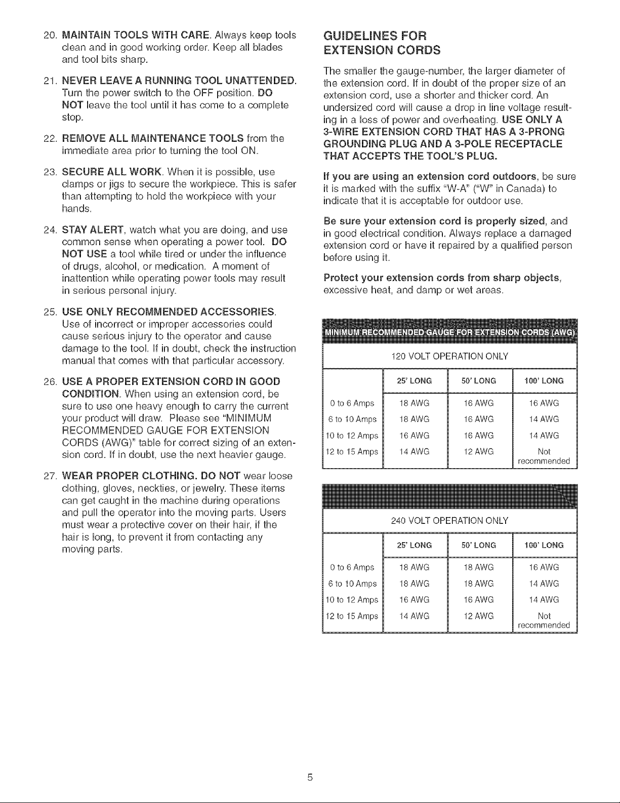
26, USE A PROPER EXTENSION CORD IN GOOD
CONDITION, When using an extension cord, be
sure to use one heavy enough to carry the current
your product will draw, Please see "MiNiMUM
RECOMMENDED GAUGE FOR EXTENSION
CORDS (AWG)" table for correct sizing of an exten-
sion cord, if in doubt, use the next heavier gauge,
27, WEAR PROPER CLOTHING. DO NOT wear loose
clothing, gloves, neckties, or jewelry, These items
can get caught in the machine during operations
and pull the operator into the moving parts, Users
must wear a protective cover on their hair, if the
hair is long, to prevent it from contacting any
moving parts,
GUIDEUNES FOR
EXTENSUON CORDS
The smaller the gauge-number, the larger diameter of
the extension cord, if in doubt of the proper size of an
extension cord, use a shorter and thicker cord, An
undersized cord wiii cause a drop in line voltage result-
ing in a loss of power and overheating, USE ONLY A
3-WIRE EXTENSION CORD THAT HAS A 3-PRONG
GROUNDING PLUG AND A 3-POLE RECEPTACLE
THAT ACCEPTS THE TOOL'S PLUG.
if you are using an extension cord outdoors, be sure
it is marked with the suffix "W-A" ("W" in Canada) to
indicate that it is acceptable for outdoor use,
Be sure your extension cord is property sized, and
in good electrical condition, Always replace a damaged
extension cord or have it repaired by a qualified person
before using it,
Protect your extension cords from sharp objects,
excessive heat, and damp or wet areas,
120 VOLT OPERATION ONLY
25' LONG 50' LONG 100' LONG
0 to 6 Amps
6 to 10 Amps
10to 12 Amps
12 to 15 Amps
18 AWG
18 AWG
16 AWG
14 AWG
16 AWG
16 AWG
16 AWG
12 AWG
16 AWG
14 AWG
14 AWG
Not
recommended
240 VOLT OPERATION ONLY
0 to 6 Amps
6 to 10 Amps
10to 12 Amps
12 to 15 Amps
25' LONG
18 AWG
18 AWG
16 AWG
14 AWG
50' LONG
18 AWG
18 AWG
16 AWG
12 AWG
100' LONG
16 AWG
14 AWG
14 AWG
Not
recommended
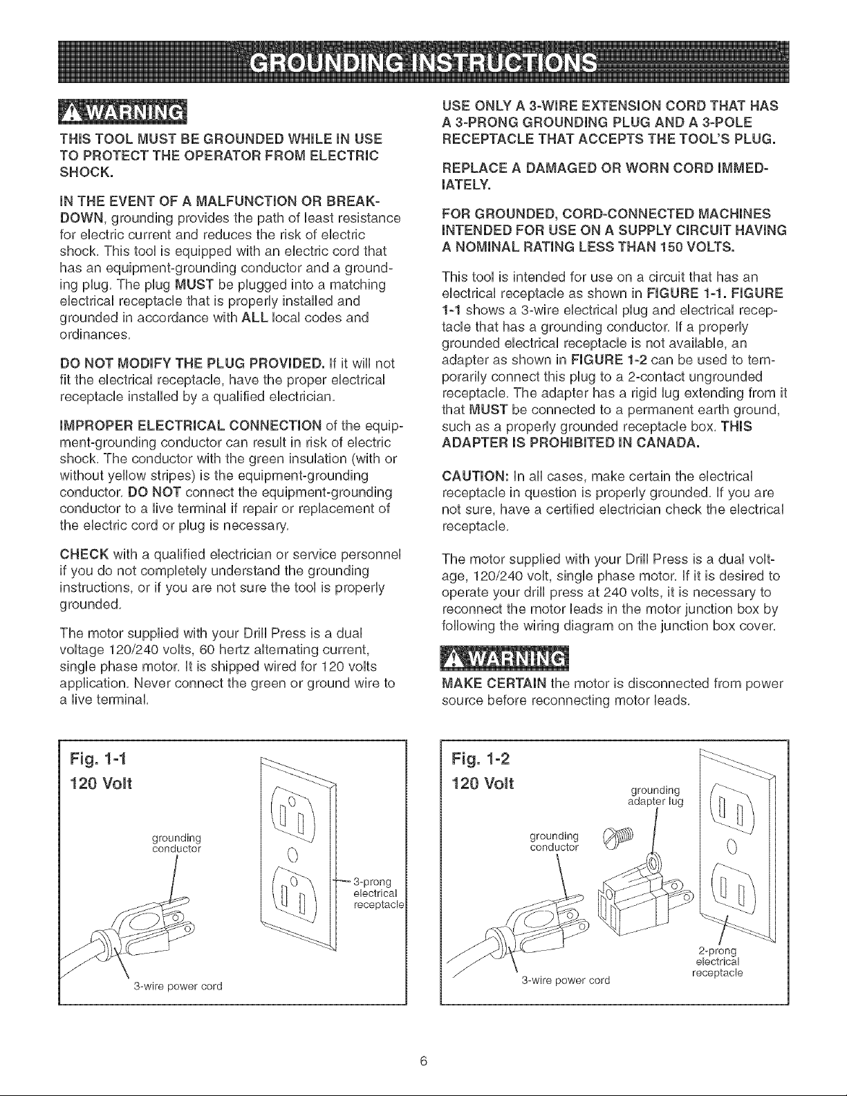
THINSTOOL MUST BE GROUNDED WHmLE mNUSE
TO PROTECT THE OPERATOR FROM ELECTRmC
SHOCK.
mNTHE EVENT OF A MALFUNCTmON OR BREAK-
DOWN, grounding provides the path of Ueastresistance
for eUectriccurrent and reduces the risk of eUectric
shock. This tooUis equipped with an eUectric cord that
has an equipment-grounding conductor and a ground-
ing pUug.The pUugMUST be pUugged into a matching
eUectdcaUreceptacle that is propedy installed and
grounded in accordance with ALL UocaUcodes and
ordinances.
DO NOT MODIFY THE PLUG PROVIDED. ff it wHUnot
fit the eUectdcaUreceptacUe, have the proper eUectdcaU
receptacle installed by a qualified electrician.
IMPROPER ELECTRICAL CONNECTION of the equip°
ment-grounding conductor can result in risk of electric
shock. The conductor with the green insulation (with or
without yellow stripes) is the equipment-grounding
conductor. DO NOT connect the equipment-grounding
conductor to a live terminal if repair or replacement of
the electric cord or plug is necessary.
CHECK with a qualified electrician or service personnel
if you do not completely understand the grounding
instructions, or if you are not sure the tool is properly
grounded.
The motor supplied with your Drill Press is a dual
voltage 120/240 volts, 60 hertz alternating current,
single phase motor, It is shipped wired for 120 volts
application, Never connect the green or ground wire to
a live terminal,
USE ONLY A 3-WIRE EXTENSION CORD THAT HAS
A 3-PRONG GROUNDING PLUG AND A 3-POLE
RECEPTACLE THAT ACCEPTS THE TOOL'S PLUG.
REPLACE A DAMAGED OR WORN CORD IMMED-
IATELY.
FOR GROUNDED, CORD-CONNECTED MACHINES
INTENDED FOR USE ON A SUPPLY CIRCUIT HAVING
A NOMINAL RATING LESS THAN 150 VOLTS.
This tool is intended for use on a circuit that has an
electrical receptacle as shown in FIGURE 1-1. FIGURE
1-1 shows a 3-wire electrical plug and electrical recep-
tacle that has a grounding conductor. If a properly
grounded electrical receptacle is not available, an
adapter as shown in FIGURE 1-2 can be used to tem-
porarily connect this plug to a 2-contact ungrounded
receptacle. The adapter has a rigid lug extending from it
that MUST be connected to a permanent earth ground,
such as a properly grounded receptacle box. THIS
ADAPTER IS PROHIBITED IN CANADA.
CAUTION: In all cases, make certain the electrical
receptacle in question is properly grounded. If you are
not sure, have a certified electrician check the electrical
receptacle.
The motor supplied with your Drill Press is a dual volt-
age, 120/240 volt, single phase motor. If it is desired to
operate your drill press at 240 volts, it is necessary to
reconnect the motor leads in the motor junction box by
following the wiring diagram on the junction box cover.
MAKE CERTAIN the motor is disconnected from power
source before reconnecting motor leads.
Fig. 1-1
120 Volt
grounding
conductor
3-wire power cord
3-prong
electrical
receptacle
Fig. 1-2
120 Volt
grounding
conductor
3-wire power cord
grounding
2-prong
electrical
receptacle

it is aUsonecessary to repUacethe 120 voUtpUug,sup-
plied with the motor, with a UL/CSA Listed pUugsuitabb
for 240 voUtsand rated current of the drHUpress. Contact
a bcaU qualified eUectrbian for proper procedures to
install the pUug.The drHUpress must compUy with aH
bcaU and nationaU eUectrbaUcodes after the 240 voUt
pUugis installed.
The drHUpress with a 240 voUtpUugshouUd onUybe
connected to an outlet having the same configuration
as the pUugshown in FIGURE 1-3. No adapter is avaiP
able or should be used with the 240 volt plug.
Fig. 1-3
240 Volt
current carrying
prongs
grounding blade is
longest of the 3 blades
grounded outlet box
6)
MAKE CERTAIN the receptacle in question is properly
grounded. If you are not sure have a qualified ebctric-
ian check the receptacle.
This Drill Press is for indoor use only. Do not expose to
rain or use in damp locations.
SPECIFIC SAFETY INSTRUCTIONS
The operation of any drill press can result in debris
being thrown into your eyes, which can result in severe
eye damage. ALWAYS WEAR EYE PROTECTION. Any
power tool can throw debris during operations, which
could cause severe and permanent eye damage.
Everyday eyeglasses are NOT safety glasses.
ALWAYS wear Safety Goggles (that comply with ANSI
standard Z87.1) when operating power tools. Safety
Goggles are available at Sears Retail Stores.
Basic precautions should always be followed when
using your drill press. To reduce the risk of injury, ebc-
trical shock or fire, comply with the safety rules listed
below:
1. READ and understand the instruction manual
before operating the drill press.
2, AVOID AWKWARD OPERATIONS AND HAND
POSITIONS. A sudden slip could cause a serious
injury.
3. CHECK all drill bits, cutting tools, sanding drums, or
other accessories for damage before installing in
the drill press chuck. Damaged items can cause
damage to the drill press and or serious injury.
4. Before leaving the drill press, LOCK or REMOVE
the ON/OFF switch/key to prevent unauthorized
use,
5, DO NOT install or use any drill bit that exceeds
7-inches in length or that extends 6-inches below
the chuck jaws. The drill bit can suddenly bend or
break.
6. DO NOT try to drill a workpiece that is too small to
be securely held to the table or in a vise.
7. DO NOT operate this drill press until it is assembled
and installed according to the instruction manual.
8. DO NOT leave the drill press plugged into the ebc-
trical outlet. Unplug the drill press from the outlet
when not in use and before servicing, changing bits
and cleaning.
9. DO NOT USE router bits, shaper cutters, circle (fly)
cutters, rotary planers or wire wheels in this drill
press.
10. FOLLOW all electrical and safety codes, including
the National Electric Code (NEC) and the
Occupational Safety and Health Regulations
(OSHA). All electrical connections and wiring should
be made by qualified personnel only.
11, LET THE CHUCK REACH FULL SPEED before
starting drill operations,
12, MAKE SURE there are no foreign objects, nails,
stones in the workpiece.
13, NEVER PERFORM LAYOUT, ASSEMBLY OR
SETUP WORK on the tabb/work area when the
drill press is running,
14, NEVER START THE DRILL PRESS BEFORE
CLEANING THE TABLE OF ALL OBJECTS (tools,
scrap pieces, etc.). Debris can be thrown at high
speed.
15. NEVER START THE DRILL PRESS with the drill
bit, cutting tool, or sanding drum against the work-
piece. Loss of control of the workpiece can cause
serious injury,
16, OBTAIN ADVICE FROM YOUR SUPERVISOR,
instructor, or another qualified person if you are not
familiar with the operation of this drill press,
17, PROPERLY SUPPORT long or wide workpiece and
clamp to the table,
18, PROPERLY SECURE the drill bit, cutting tool, or
sanding drum in the chuck before operating the drill
press,
19, REPLACE a damaged cord immediately, DO NOT
use a damaged cord or plug, if the drill press is not
operating properly, or has been damaged, left out-
doors or has been in contact with water, return it to
a Sears Service Center,
20, SECURE the drill press to the floor or work bench,
Vibration can cause the drill press to slide, walk or
tip over,
21,SECUREtheworkpbcefirmlyagainstthetabb,
Donotattempttodrilla workpbcethatdoesnot
haveafiatsurfaceagainstthetabb,orthatis not
securedbya vise, Preventtheworkpbcefrom
rotatingbydampingit tothetabb orby securingit
againstthedrillpresscolumn,Lossof controlof
theworkpbcecancauseseriousinjury,
22,SECURELYLOCKtheheadandtabbsupportto
thecolumn,andthetabb to thetabbsupport
beforeoperatingthedrillpress,
23,Thedrillpressisdesignedforhomeuseorlight
commercialdutyONLY,
24,TOREDUCETHERISKOFELECTRICAL
SHOCK,donotuseoutdoors.Donotexposeto
rain,Storeindoorsin a dryarea,
25,TURNTHEDRILLPRESSOFFandunplugfrom
powersource,Waitforthedrillbit,cuttingtool,or
sandingdrumtocometoa compbteSTOPbefore
cleaningoffthetabb/workarea,removingorsecur-
ingworkpiece,orchangingsetup,
26,USEonlydrillbits,cuttingtools,sandingdrums,or
otheraccessorieswithpropershanksizerecom-
mendedin thisinstructionmanual,Thewrongsize
shankcancausedamagetothedrillpressand/or
seriousinjury,
27,USEonlyasdescribedin thisinstructionmanual,
USEaccessoriesonlyrecommendedbySears,
28,USERECOMMENDEDSPEEDSforalloperations,
Otherspeedsmaycausethemachinetomalfunc-
tioncausingdamagetothedrillpressandor
seriousinjury,
29,informationregardingthesafeandproperoperation
ofthistoolisalsoavailablefromthefollowing
sources:
PowerToolinstitute
1300SummerAvenue
Cleveland,OH44115-2851
www, powertoolinstitute,org
National Safety Council
1121 Spring Lake Drive
Itasca, IL 60143o3201
American National Standards institute
25 West 43rd Street, 4th floor
New York, NY 10036
30,
ANSi 01,1 Safety Requirements for
Woodworking Machines, and the
U,S, Department of Labor regulations
www, osha,cLOJ
SAVE THESE INSTRUCTIONS, Refer to them
frequently and use them to instruct other users,
ADDITIONAL SAFETY RULES
FOR THE LASER
1, LASER LIGHT - DO NOT STARE INTO BEAM,
APERTURE, or into a reflection from a mirror-like
surface,
2, AVOID EXPOSURE - LASER LIGHT IS EMITTED
FROM BOTH SIDES OF LASER ASSEMBLY,
Use of controls or adjustments, or performance of
procedures other than those specified herein may
result in hazardous laser light exposure,
3, DO NOT DISASSEMBLE LASER MODULE, The
laser is a CLASS mmLASER PRODUCT that can
emit laser power up to 1 mW MAX at 635 rim,
which could result in exposure with the module
disassembled, The laser unit complies with 21
CFR 1040,10 and 1040,11,
4, USE OF CONTROLS OR ADJUSTMENTS OR
PERFORMANCE OF PROCEDURES OTHER
THAN THOSE SPECIFIED HEREIN MAY RESULT
IN HAZARDOUS RADIATION EXPOSURE.
AVAILABLE ACCESSORUES
Visit your Sears Hardware Department or see the
Craftsman Power and Hand Tool Catalog for the follow-
ing accessories,
ITEM STOCK NUMBER
* Circle Cutter 25293
* Clamping Lit 26426
* 8-in, Vise 24077
* 4-in, Vise 24081
* 3-in, Vise 24071
* 21 pc, Sanding Drum Kit 25262
* 7 pc, Forstner Bit Set 25389
Sears may recommend other accessories not listed in
this manual,
See your nearest Sears Hardware Department or
Craftsman Power and Hand Tool Catalog for other
accessories,
Do not use any accessory unless you have completely
read the instruction Manual for that accessory,
Use only accessories recommended for this drill press,
Using other accessories may cause serious injury and
cause damage to the drill press,
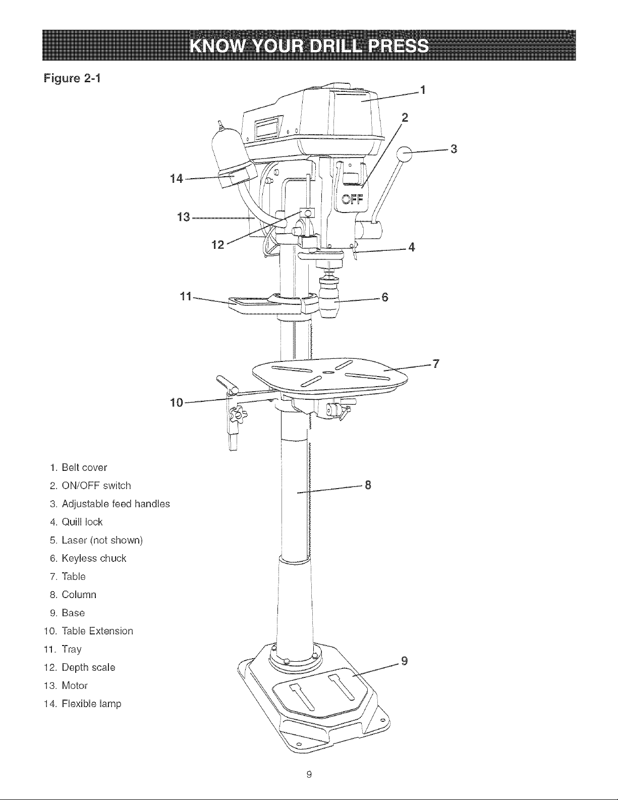
Figure 2-1
i II
12
1, BeHtcover
2, ON/OFF switch
3, AdjustabHe feed handHes
4, QulH Hock
5, Laser (not shown)
6, KeyHess chuck
7, TaMe
8, CoHumn
9, Base
10, TaMe Extension
11, Tray
12, Depth scaHe
13, Motor
14, FHexibHeHamp
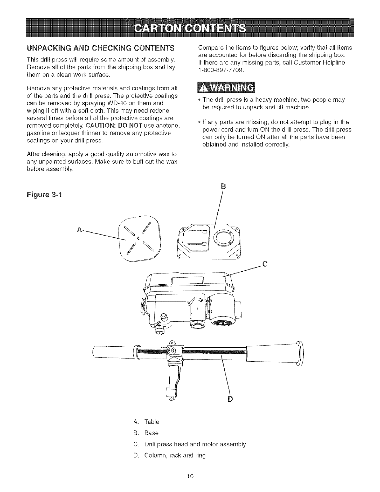
UNPACKUNG AND CHECKUNG CONTENTS
This drHUpress wHUrequire some amount of assemMy,
Remove aH of the parts from the shipping box and Uay
them on a clean work surface,
Remove any protective materiab and coatings from aH
of the parts and the drHUpress, The protective coatings
can be removed by spraying WD-40 on them and
wiping it off with a soft cloth, This may need redone
severaU times before aH of the protective coatings are
removed compbteUy, CAUTION: DO NOT use acetone,
gasoline or Uacquer thinner to remove any protective
coatings on your drHUpress,
After cleaning, apply a good quality automotive wax to
any unpainted surfaces, Make sure to buff out the wax
before assembly,
Figure 3-1
Compare the items to figures below; verify that all items
are accounted for before discarding the shipping box,
if there are any missing parts, call Customer Helpline
1-800-897-7709,
The drill press is a heavy machine, two people may
be required to unpack and lift machine,
if any parts are missing, do not attempt to plug in the
power cord and turn ON the drill press, The drill press
can only be turned ON after all the parts have been
obtained and installed correctly,
B
}
A, Table
B, Base
C, Drill press head and motor assembly
D, Column, rack and ring
10
Figure 3-2
E
F
BB
G H
Z
JKL
E, TaMe extension
F, Knob
G, TaMe extension support
H, Keyiess chuck
i, Chuck arbor
J, 2,5mm Hex wrench
K, 3mm Hex wrench
L, 5mm Hex wrench
M, TaMe rabe/Mower handle
N, Spindie adapter remover
O, Knob (2)
P, Tray, back
Q, Tray
R, CHamp pilate
S, Pan head screw M5 x 35mm (2)
T, Hex nut M5 (2)
U, Adjustabie Feed handie
V, Hex head screw MIO x 40mm (4)
W, TaMe rotation Hockhandie
X, TaMe height Hockhandie
Y, Hex head screw M8-1,25 x 125mm (4)
Z, Fiat Washer M8 (8)
AA, Hex Nut M8-1,25 (4)
BB, Lock Washer M8 (4)
Figure 3-3
CC, Laser assembly
DD, Clamp
EE, Alignment pin (not shown)
Figure 3-4
FR Light assembHy
GG, Hex socket head screw M6 x 16mm (2)
HH, Lock washer M6 (2)
Hi, Cord sieeve
JJ, CHamp
KK, Adhesive cord champs (2)
(not shown)
FF
11
TOOLS REQUIRED
The following toob are needed for assemMy and align-
ment. Note: hex wrenches are provided. The remaining
toob are typbaU shop tooUsand are not included with
your drHUpress.
12mm Open end wrench 13mm Open end wrench
#2 PhHHpsscrewdriver Hammer and Mock of wood
The drHUpress is a heavy machine; two peopb may
be required for certain assemMy operations.
DO NOT assembb the drHUpress until you are sure
the tooUis unpUugged.
DO NOT assembb the drHUpress until you are sure
the power switch is in the "OFF" position.
For your own safety, DO NOT connect the drHUpress
to the power source until the machine is completely
assembled and you read and understand the entire
Instruction Manual.
COLUMN, BASE and TABLE ASSEMBLY
Figure 4-1
i [
Figure 4-2
O
G
2, Attach the table raising and lowering handle (D) on
the worm gear shaft (E) and tighten the set screw
(F) against the fiat (G) on the worm gear shaft, See
Figure 4-2,
Figure 4-3
Attach the column (A) to the base (B) using the
four MIO x 40mm hex head screws (C).
See Figure 4-1.
3. Thread the stud of the table lock handle (H) into the
hob (I) in the rear of the table bracket. See Figure
4-3.
Figure 4-4 J
K
12
4, Lay the table (J) upside down and place the table
extension support (K) into the bottom of the table.
NOTE: The table extension support can be posi-
tioned either to the right or left. See Figure 4-4.
Figure 4-5 Figure 4-7
Q
/C_
M
5, Hace the clamp plate (L) over the tame extension
support and attach it with two threaded knobs (M), 8, Hace tame extension (Q) into tame extension sup-
port, See Figure 4-7,
Figure 4-6
J
/
Figure 4-8
/,
R y
N
6,
7,
AssemMe the threaded end of the tame rotation
lock handle (N) into hole (0) in the front, right side-
of the tame support, Do not completely tight handle
at this time, Note: The tame rotation lock handle is
the smaller of the two lock handles, See Figure 4-6
Insert the tame (J) into the mounting hole (P) tame
support, Rotate the tame to desired position and
tighten tame rotation locking handle,
See Figure 4-6,
9, Assemble the threaded knob (R) into the weld nut
(S) on the table extension support, See Figure 4-8,
13
Figure 4-9 DRILL PRESS HEAD AND
MOTOR ASSEMBLY
X
\
T
The drHUpress is a heavy machine; two peopb may
be required for certain assemMy operations,
MAKE CERTAIN the drHUpress is disconnected from
the power source,
Figure 5-1 A
V
10, LooseUy assembb the tray back (T) to the tray (U)
with two pan head screws M5 x 35mm (V) and M5
hex nuts (X), See Figure 4-9,
Figure 4-10
U
B
1, Seat the drHUpress head (A) on the coUumn (B),
See Figure 5-1,
Figure 5-2
11, Slide the tray (U) down onto the column (A) until it
rests on the ring (Y) and tighten both screws,
See Figure 4-10
2, Align the drill press head with the table and base
and tighten the two head locking screws (C),
See Figure 5-2,
14
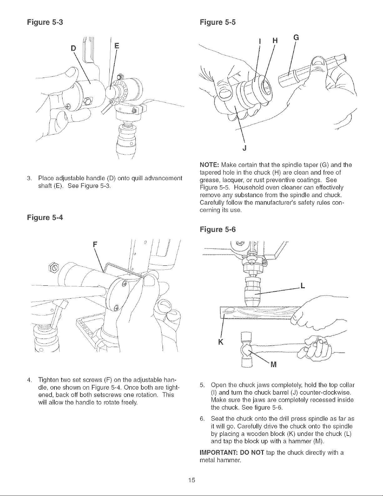
Figure 5-3 Figure 5-5
DE
G
3, Piace adjustabie handie (D) onto quHi advancement
shaft (E), See Figure 5-3,
Figure 5-4
F
NOTE: Make certain that the spindie taper (G) and the
tapered hob in the chuck (H) are clean and free of
grease, iacquer, or rust preventive coatings, See
Figure 5-5 Househoid oven cieaner can effectiveiy
remove any substance from the spindie and chuck,
Carefuliy follow the manufacturer's safety rubs con-
cerning its use,
Figure 5-6
K
4, Tighten two set screws (F) on the adjustable han-
dle, one shown on Figure 5-4, Once both are tight-
ened, back off both setscrews one rotation, This
will allow the handle to rotate freely,
5, Open the chuck jaws completely, hold the top collar
(I) and turn the chuck barrel (J) counter-clockwise,
Make sure the jaws are completely recessed inside
the chuck, See figure 5-6,
6, Seat the chuck onto the drill press spindle as far as
it wiii go, Carefully drive the chuck onto the spindle
by placing a wooden block (K) under the chuck (L)
and tap the block up with a hammer (M),
IMPORTANT: DO NOT tap the chuck directly with a
metal hammer,
15
LASER ASSEMBLY Figure 6-3
MAKE CERTAIN the drill press is disconnected from
the power source,
LASER LIGHT -DO NOT STARE INTO BEAM,
APERTURE, or into a reflection from a mirrorqke
surface,
Figure 6-1
5,
6,
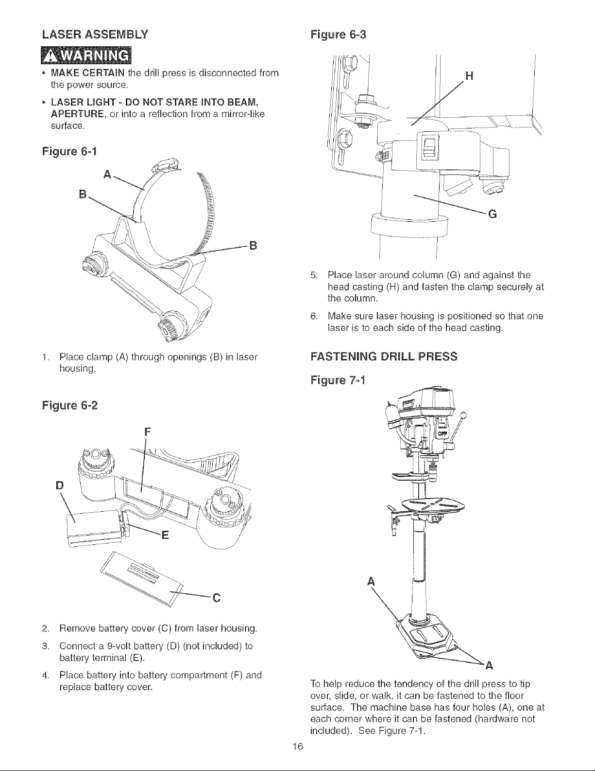
Hace Uaser around coUumn (G) and against the
head casting (H) and fasten the damp secureUy at
the coUumn,
Make sure Uaserhousing is positioned so that one
Uaseris to each side of the head casting,
1, Place clamp (A) through openings (B) in laser
housing,
Figure 6-2
F
D
E\
C
2, Remove battery cover (C) from laser housing,
3, Connect a 9-volt battery (D) (not included) to
battery terminal (E),
4, Place battery into battery compartment (F) and
replace battery cover,
16
A
To help reduce the tendency of the drill press to tip
over, slide, or walk, it can be fastened to the floor
surface, The machine base has four hobs (A), one at
each corner where it can be fastened (hardware not
included), See Figure 7-1,
DONOTexposethedrillpressto rainor operatethe
in damplocations,
MAKESUREallpartshavebeenassembledcorrectly
andarein workingorder,
SWITCH OPERATION
CHmLDPROOF THE WORKSHOP AREA by removing
switch keys, unplugging tools from the electrical recep-
tacles, and using padlocks,
Figure 8-1
Figure 8-2
4.
8.
8.
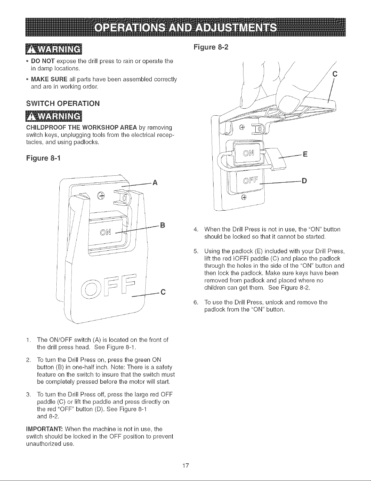
When the Drill Press is not in use, the "ON" button
should be locked so that it cannot be started,
Using the padlock (E) included with your Drill Press,
lift the red iOFF[ paddle (C) and place the padlock
through the hobs in the side of the "ON" button and
then lock the padlock, Make sure keys have been
removed from padlock and placed where no
children can get them, See Figure 8-2,
To use the Drill Press, unlock and remove the
padlock from the "ON" button,
1, The ON/OFF switch (A) is located on the front of
the drill press head, See Figure 8-1,
2. To turn the Drill Press on, press the green ON
button (B) in one-half inch, Note: There is a safety
feature on the switch to insure that the switch must
be completely pressed before the motor will start,
8. To turn the Drill Press off, press the large red OFF
paddle (C) or lift the paddle and press directly on
the red "OFF" button (D), See Figure 8-1
and 8-2,
IMPORTANT: When the machine is not in use, the
switch should be locked in the OFF position to prevent
unauthorized use,
17
FLEXUBLE LAMP
To reduce the risk of fire, use 40 watt or less, 120 volt,
reflector track-type Hight buib (not supplied), DO NOT
use a standard househoid Hight buib, The reflector track-
type Hightbuib shouid not extend bellow the iamp shade,
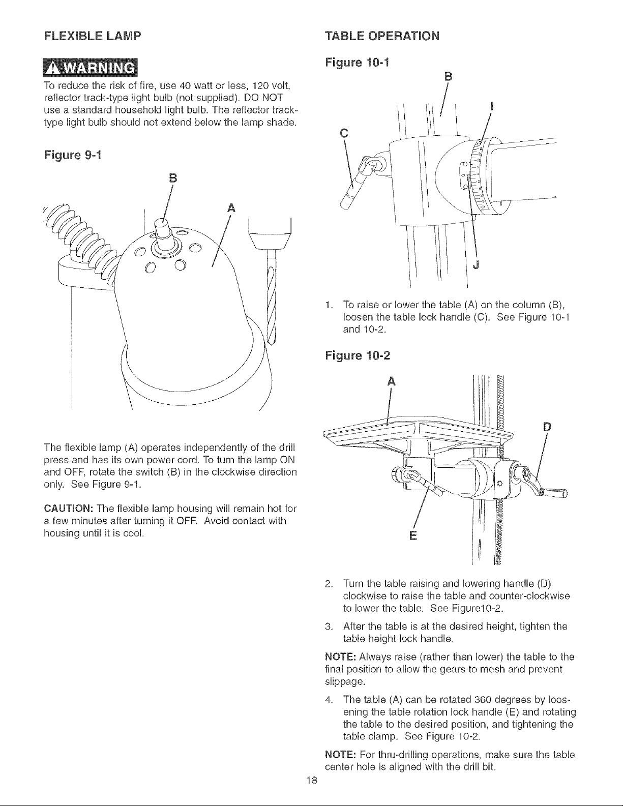
Figure 9-1
B
A
©©
The flexible lamp (A) operates independently of the drill
press and has its own power cord, To turn the lamp ON
and OFF, rotate the switch (B) in the clockwise direction
only, See Figure 9-1,
CAUTION: The flexible lamp housing wiii remain hot for
a few minutes after turning it OFR Avoid contact with
housing until it is cook
TABLE OPERATION
Figure 10-1
B
C
1, To raise or lower the table (A) on the column (B),
loosen the table lock handle (C), See Figure 10-1
and 10-2,
Figure 10-2
A
E
18
2, Turn the table raising and lowering handle (D)
clockwise to raise the table and counter-clockwise
to lower the table, See Figure10-2,
3, After the table is at the desired height, tighten the
table height lock handle,
NOTE: Always raise (rather than lower) the table to the
final position to allow the gears to mesh and prevent
slippage,
4, The table (A) can be rotated 360 degrees by loos-
ening the table rotation lock handle (E) and rotating
the table to the desired position, and tightening the
table clamp, See Figure 10-2,
NOTE: For thru-drilling operations, make sure the table
center hob is aligned with the drill bit,
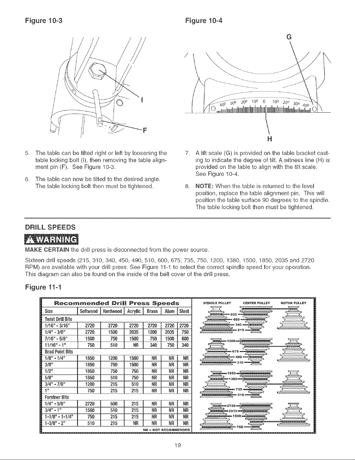
Figure 10-3 Figure 10-4
G
20 o 100 0 10° 200 300
5,
6,
The tame can be tilted right or Ueftby Uoosening the
tame Uocking bout (U),then removing the tame align-
ment pin (F), See Figure 10-3,
The tame can now be tilted to the desired angUe,
The tame Uocking bout then must be tightened,
7,
8,
H
A tilt scaUe (G) is provided on the tame bracket cast-
ing to indicate the degree of tilt, A witness Hne (H) is
provided on the tame to align with the tilt scaUe,
See Figure 10-4,
NOTE: When the tame is returned to the UeveU
position, repUacethe tame alignment pin, This will
position the table surface 90 degrees to the spindle,
The table locking bolt then must be tightened,
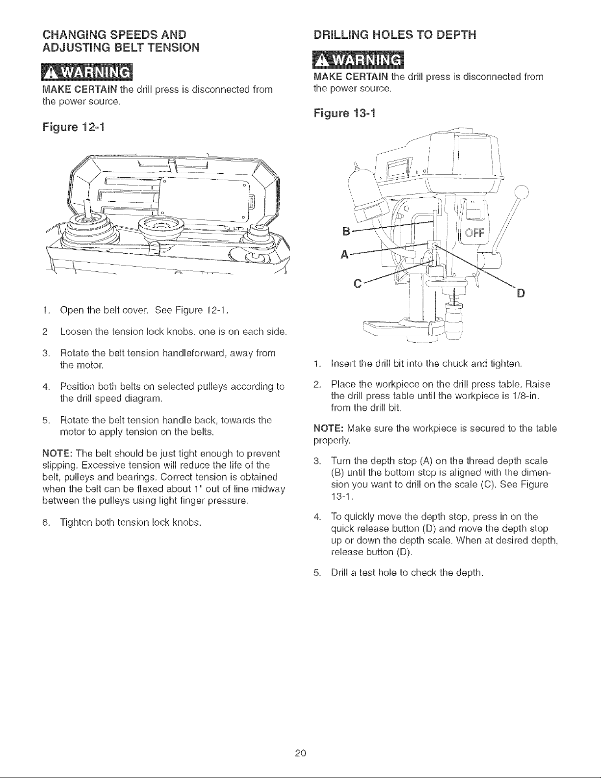
DRILL SPEEDS
MAKE CERTAIN the drill press is disconnected from the power source,
Sixteen drill speeds (215, 310,340, 450, 490, 510, 600, 675,735, 750, 1200, 1380, 1500, 1850, 2035 and 2720
RPM) are available with your drill press, See Figure 11-1 to select the correct spindle speed for your operation,
This diagram can also be found on the inside of the belt cover of the drill press,
Figure 11-1
Recommended Dri|| Press Speeds
s ,o !so 00dIB0,d ,°0dI 0,y,0I B 0°,I..mIst001
TwistDrillBits
1/1B"=3/1B"
1t4"- 3/8"
7/1B"=5/8"
11116"=1"
BradPeintBits
1/8"-1/4"
3/8"
1/2"
5/8"
3/4"o7/8"
1 _
FerstnerBits
1/4"=5/8"
3/4"=1"
1ol/8"=1ol/4"
1o3/8"=2"
2720 2720 2720 2728 2720 2720
2728 1500 2835 !200 2835 750
1580 750 1500 758 1500 BOO
750 5!B NR 340 750 340
1850 1208 1500 N£ NR NR
1850 750 1500 NR NR NR
1850 758 750 NR NR NR
1850 518 750 NR BR NR
1280 215 510 NR NR NR
750 215 215 NR NR NB
2720 BOB 215 NR NR NR
1580 510 215 NR NR NR
750 215 215 N£ NR NR
510 215 NR NR NR NR
NR = NOT R6COMMEN#E#
6P|H6LE PULLEY CENTE6 PULLEY _OTOR PULLEY
600
_45
19
CHANGUNG SPEEDS AND DF_ULUNG HOLES TO DEPTH
ADJUSTING BELT TENSUON
MAKE CERTAIN the drill press is disconnected from
the power source,
Figure 12-1
MAKE CERTAIN the drHHpress is disconnected from
the power source,
Figure 13-1
1, Open the beHtcover, See Figure 12-1,
2 Loosen the tension lock knobs, one is on each side,
3, Rotate the belt tension handleforward, away from
the motor,
4, Position both belts on selected pulleys according to
the drill speed diagram,
5, Rotate the belt tension handle back, towards the
motor to apply tension on the belts,
NOTE: The beHtshouHd be just tight enough to prevent
shipping, Excessive tension wHHreduce the Nfeof the
beHt,puHHeysand bearings, Correct tension is obtained
when the belt can be flexed about 1" out of line midway
between the puHHeysusing Hightfinger pressure,
6, Tighten both tension lock knobs,
A
CD
1,
2,
Insert the drill bit into the chuck and tighten,
Place the workpiece on the drill press table, Raise
the drill press table until the workpiece is 1/8-in,
from the drill bit,
NOTE: Make sure the workpiece is secured to the table
properly,
3, Turn the depth stop (A) on the thread depth scale
(B) until the bottom stop is aligned with the dimen-
sion you want to drill on the scab (C), See Figure
13-1,
4, To quickly move the depth stop, press in on the
quick release button (D) and move the depth stop
up or down the depth scab, When at desired depth,
release button (D),
5, Drill a test hole to check the depth,
2O
ADJUSTING RETURN SPRING
The drHHchuck wHHautomaticaHHyreturn showily to its
upper position when the handHe is reHeased, The return
spring was properHy adjusted at the factory, However, to
adjust, if necessary:
,, MAKE CERTAIN the drill press is disconnected from
the power source,
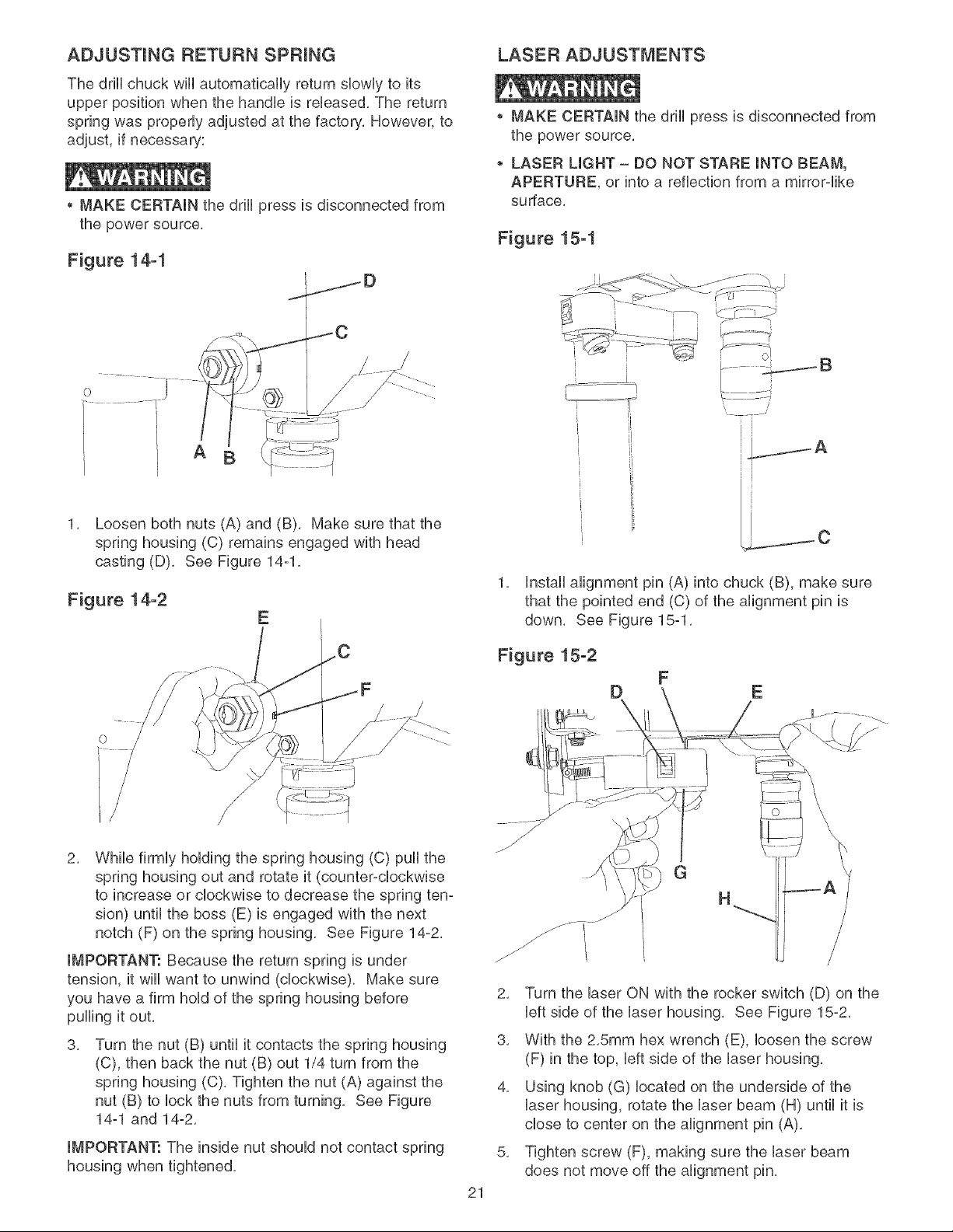
Figure 14-1
A
1, Loosen both nuts (A) and (B), Make sure that the
spring housing (C) remains engaged with head
casting (D), See Figure 14-1,
Figure 14-2
LASER ADJUSTMENTS
,, MAKE CERTAIN the drHHpress is disconnected from
the power source,
LASER LIGHT - gO NOT STARE INTO BEAM,
APERTURE, or into a reflection from a mirror-Hike
surface,
Figure 15-1
IB
i
t
t i
t
t
t
i
t
t
1, HnstaHHalignment pin (A) into chuck (B), make sure
that the pointed end (C) of the alignment pin is
down, See Figure 15-1,
Figure 15-2
DFE
2, While firmHy hoHding the spring housing (C) puHHthe
spring housing out and rotate it (counter-cHockwise
to increase or cHockwise to decrease the spring ten-
sion) untiHthe boss (E) is engaged with the next
notch (F) on the spring housing, See Figure 14-2,
IMPORTANT: Because the return spring is under
tension, it wiHHwant to unwind (clockwise). Make sure
you have a firm hoHdof the spring housing before
puHHingit out,
3, Turn the nut (B) untiHit contacts the spring housing
(C), then back the nut (B) out 1/4 turn from the
spring housing (C), Tighten the nut (A) against the
nut (B) to Hockthe nuts from turning, See Figure
14-1 and 14-2,
IMPORTANT: The inside nut shouHd not contact spring
housing when tightened,
J
21
/ G
H
2, Turn the Haser ON with the rocker switch (D) on the
Heftside of the Haser housing, See Figure 15-2,
3, With the 2,5mm hex wrench (E), Hoosen the screw
(F) in the top, Heftside of the Haserhousing,
4, Using knob (G) Hocated on the underside of the
Haserhousing, rotate the Haser beam (H) untiHit is
chose to center on the aHignment pin (A),
5, Tighten screw (F), making sure the Haserbeam
does not move off the aHignment pin,
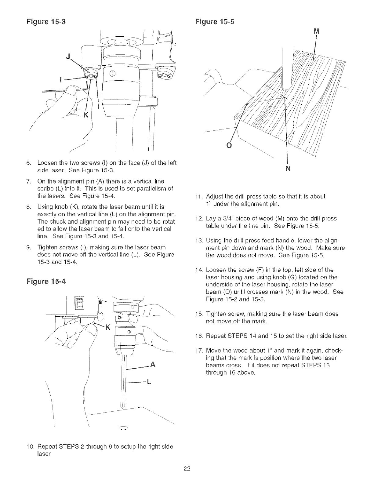
Figure 15-3 Figure 15-5
M
J
J
6, Loosen the two screws (U)on the face (J) of the bft
side Uaser, See Figure 15-3,
7, On the alignment pin (A) there is a verticaU fine
scribe (L) into it, This is used to set parafleHsm of
the Uasers, See Figure 15-4,
8, Using knob (K), rotate the Uaser beam untiUit is
exactly on the vertbaU Hne (L) on the alignment pin,
The chuck and alignment pin may need to be rotat-
ed to aflow the Uaserbeam to fail onto the vertbaU
Hne, See Figure 15-3 and 15-4,
9, Tighten screws (U), making sure the Uaserbeam
does not move off the vertbaU line (L), See Figure
15-3 and 15-4,
Figure 15-4
K
11,
12,
13,
14,
15,
16,
17,
Adjust the drill press table so that it is about
1" under the alignment pin,
Lay a 3/4" piece of wood (M) onto the drill press
table under the line pin, See Figure 15-5,
Using the drift press feed handle, lower the align-
ment pin down and mark (N) the wood, Make sure
the wood does not move, See Figure 15-5,
Loosen the screw (F) in the top, left side of the
laser housing and using knob (G) located on the
underside of the laser housing, rotate the laser
beam (0) until crosses mark (N) in the wood, See
Figure 15-2 and 15-5,
Tighten screw, making sure the laser beam does
not move off the mark,
Repeat STEPS 14 and 15 to set the right side laser,
Move the wood about 1" and mark it again, check-
ing that the mark is position where the two laser
beams cross, if it does not repeat STEPS 13
through 16 above,
\
\
10, Repeat STEPS 2 through 9 to setup the right side
laser,
22
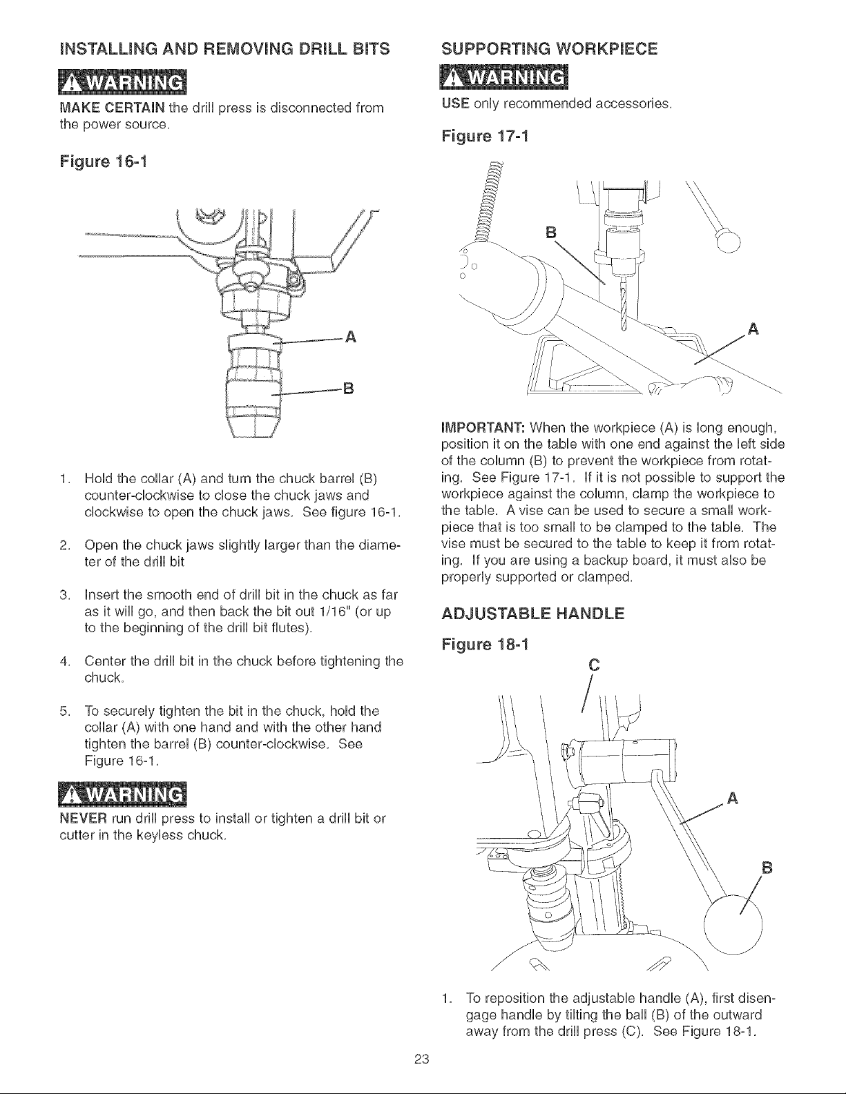
iNSTALLiNG AND REMOVING DRULL BITS SUPPORTING WOF{KPIECE
MAKE CERTAIN the drill press is disconnected from
the power source.
Figure 18-1
USE onUyrecommended accessories.
Figure 17-1
o
B
A
2,
3,
4,
5,
HoUdthe collar (A) and turn the chuck barreU (B)
counterocbckwbe to close the chuck jaws and
clockwise to open the chuck jaws. See figure 16-1.
Open the chuck jaws slightly Uarger than the diame-
ter of the drHUbit
insert the smooth end of drHUbit in the chuck as far
as it wHUgo, and then back the bit out 1/16" (or up
to the beginning of the drHUbit flutes).
Center the drHUbit in the chuck before tightening the
chuck.
To secureUy tighten the bit in the chuck, hoUdthe
collar (A) with one hand and with the other hand
tighten the barrel (B) counter-clockwise. See
Figure 16-1.
NEVER run drill press to install or tighten a drill bit or
cutter in the keyless chuck,
IMPORTANT: When the workpiece (A) is long enough,
position it on the table with one end against the left side
of the column (B) to prevent the workpiece from rotat-
ing. See Figure 17ol. if it is not possible to support the
workpiece against the column, clamp the workpiece to
the table. A vise can be used to secure a small work-
piece that is too small to be clamped to the table. The
vise must be secured to the table to keep it from rotat-
ing. if you are using a backup board, it must also be
properly supported or clamped.
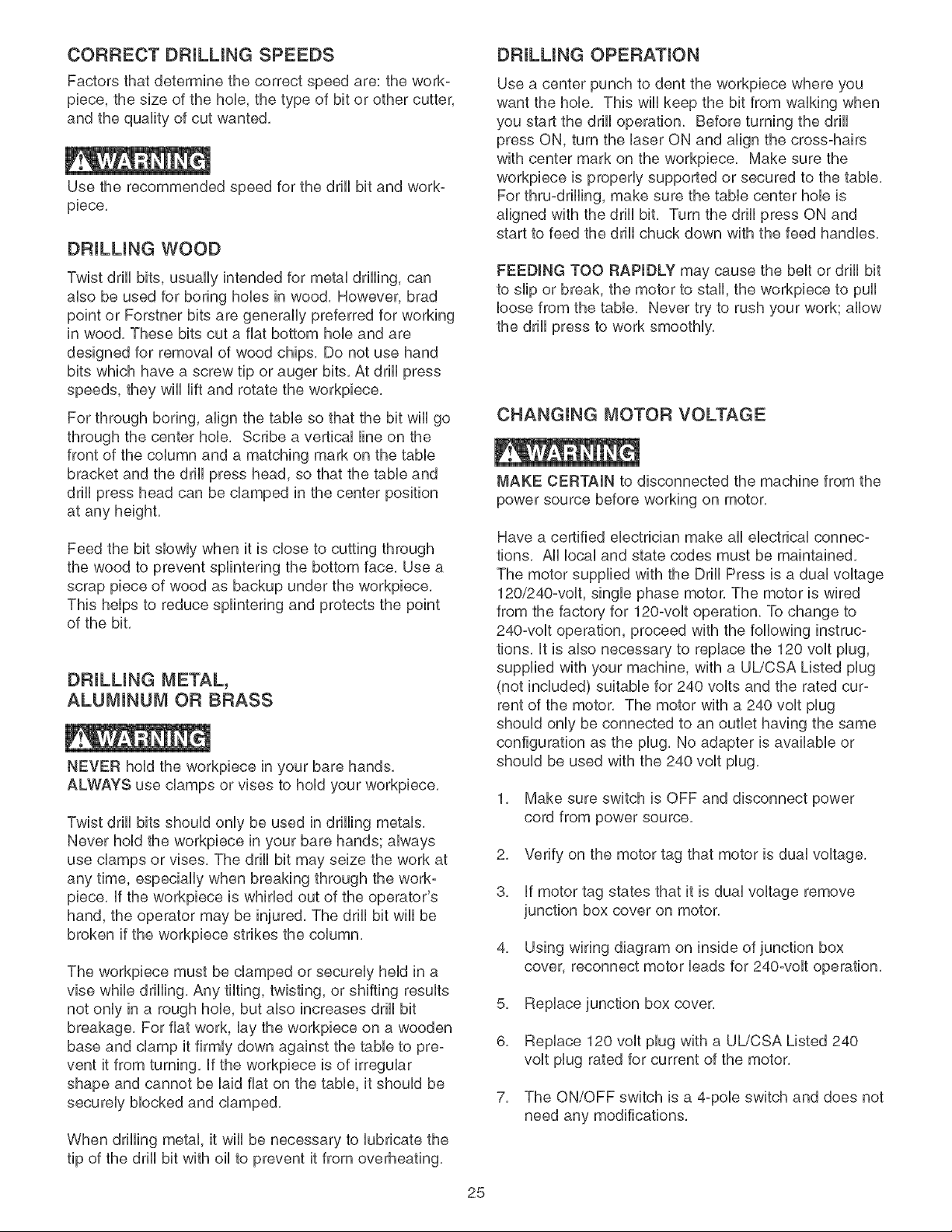
ADJUSTABLE HANDLE
Figure 18-1
C
A
B
23
1, To reposition the adjustable handle (A), first disen-
gage handle by tilting the ball (B) of the outward
away from the drill press (C), See Figure 18-1,
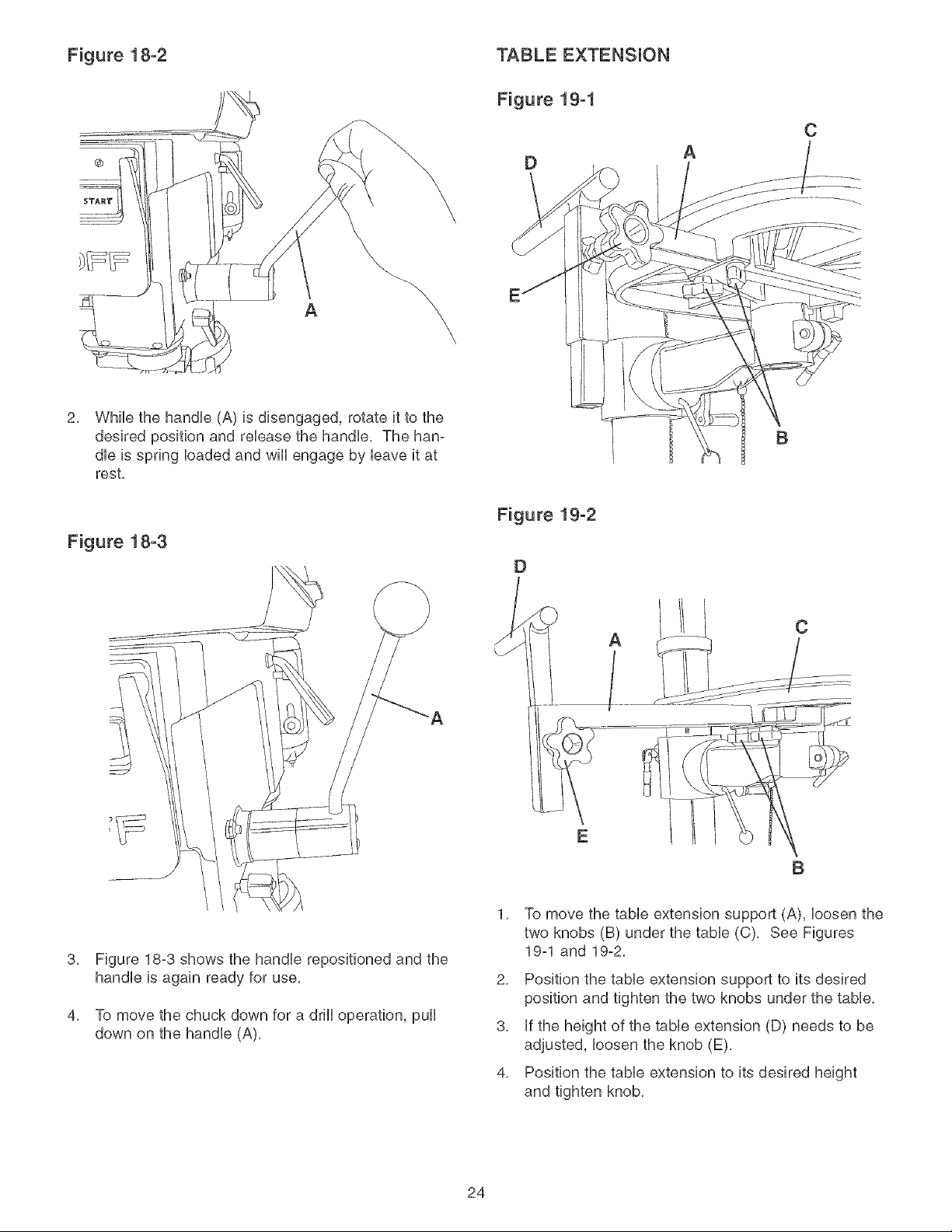
Figure 18-2
2. While the handUe (A) is disengaged, rotate it to the
desired position and reUease the handUe, The ham
due is spring Uoaded and wHUengage by Ueaveit at
rest,
Figure 18-3
TABLE EXTENSUON
Figure 19-1
D
Figure 19-2
D
A
B
C
A
AC
B
3.
4.
Figure 18-3 shows the handUe repositioned and the
handUe is again ready for use,
To move the chuck down for a drHUoperation, pull
down on the handUe (A),
1. To move the table extension support (A), loosen the
two knobs (B) under the table (C), See Figures
19-1 and 19-2,
2, Position the tame extension support to its desired
position and tighten the two knobs under the tame,
3, Ufthe height of the tame extension (D) needs to be
adjusted, Uoosenthe knob (E),
4, Position the tame extension to its desired height
and tighten knob,
24
CORRECT DRiLLiNG SPEEDS
Factors that determine the correct speed are: the work-
piece, the size of the hob, the type of bit or other cutter,
and the quality of cut wanted,
Use the recommended speed for the ddH bit and work-
piece.
DRiLLiNG WOOD
Tvqst drill bits, usually intended for metai drHHng, can
abo be used for boring hobs in wood. However, brad
point or Forstner bits are generally preferred for working
in wood. These bits cut a fiat bottom hob and are
designed for removai of wood chips. Do not use hand
bits which have a screw tip or auger bits. At drill press
speeds, they will Hft and rotate the workpiece.
For through boring, align the table so that the bit will go
through the center hole. Scribe a vertical line on the
front of the column and a matching mark on the table
bracket and the drill press head, so that the table and
drill press head can be clamped in the center position
at any height.
Feed the bit slowly when it is close to cutting through
the wood to prevent splintering the bottom face. Use a
scrap piece of wood as backup under the workpiece.
This helps to reduce splintering and protects the point
of the bit.
DRULUNG METAL,
ALUMINUM OR BRASS
NEVER hold the workpiece in your bare hands,
ALWAYS use clamps or vises to hold your workpuece,
Twist drill bits should only be used in drilling metals,
Never hold the workpiece in your bare hands; always
use clamps or vises, The drill bit may seize the work at
any time, especially when breaking through the work-
piece, if the workpiece is whirled out of the operator's
hand, the operator may be injured, The drill bit wiii be
broken if the workpiece strikes the column,
The workpiece must be clamped or securely held in a
vise while drilling, Any tilting, twisting, or shifting results
not only in a rough hob, but also increases drill bit
breakage, For fiat work, lay the workpiece on a wooden
base and clamp it firmly down against the table to preo
vent it from turning, if the workpiece is of irregular
shape and cannot be laid fiat on the table, it should be
securely blocked and clamped,
When drilling metal, it wiii be necessary to lubricate the
tip of the drill bit with oil to prevent it from overheating,
DRULUNG OPERATION
Use a center punch to dent the workpiece where you
want the hob. This will keep the bit from walking when
you start the drill operation. Before turning the drill
press ON, turn the laser ON and align the cross-hairs
with center mark on the workpiece. Make sure the
workpiece is properly supported or secured to the table.
For thruodrilling, make sure the table center hob is
aligned with the drill bit. Turn the drill press ON and
start to feed the drill chuck down with the feed handles.
FEEDING TOO RAPIDLY may cause the belt or drill bit
to slip or break, the motor to stall, the workpiece to pull
loose from the table, Never try to rush your work; allow
the drill press to work smoothly,
CHANGmNG MOTOR VOLTAGE
MAKE CERTAIN to disconnected the machine from the
power source before working on motor.
Have a certified electrician make all electrical connec-
tions, All local and state codes must be maintained,
The motor supplied with the Drill Press is a dual voltage
120/240-volt, single phase motor, The motor is wired
from the factory for 120-volt operation, To change to
240-volt operation, proceed with the following instruc-
tions, it is also necessary to replace the 120 volt plug,
supplied with your machine, with a UL/CSA Listed plug
(not included) suitable for 240 volts and the rated cur°
rent of the motor, The motor with a 240 volt plug
should only be connected to an outlet having the same
configuration as the plug, No adapter is available or
should be used with the 240 volt plug,
1, Make sure switch is OFF and disconnect power
cord from power source,
2. Verify on the motor tag that motor is dual voltage.
3. if motor tag states that it is dual voltage remove
junction box cover on motor.
4, Using wiring diagram on inside of junction box
cover, reconnect motor leads for 240-volt operation,
5. Replace junction box cover.
6, Replace 120 volt plug with a UL/CSA Listed 240
volt plug rated for current of the motor,
7. The ON/OFF switch is a 4-pole switch and does not
need any modifications.
25
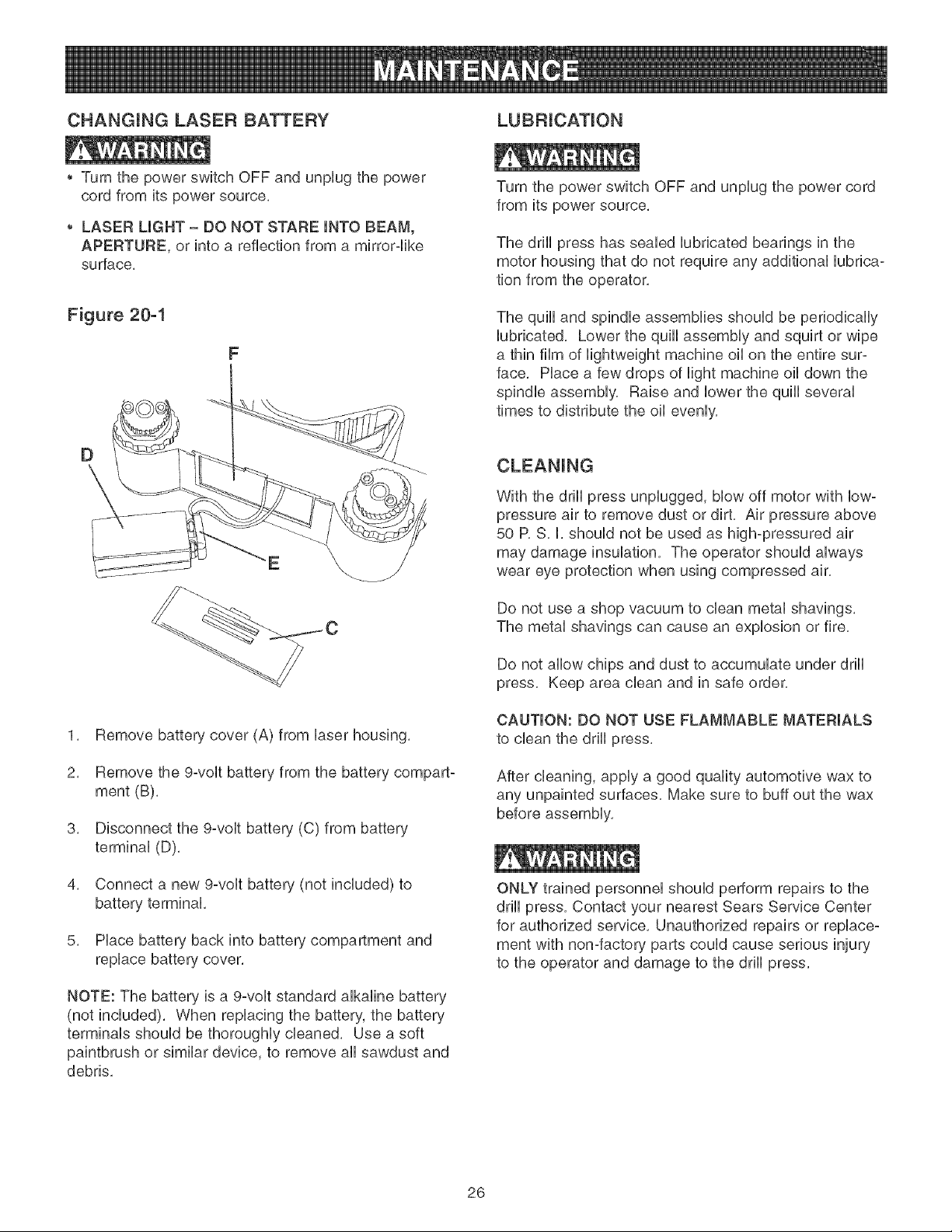
CHANGmNG LASER BATTERY
Turn the power switch OFF and unplug the power
cord from its power source,
LASER UGHT - DO NOT STARE mNTOBEAM,
APERTURE, or into a reflection from a mirror-like
surface,
Figure 20-1
F
1. Remove battery cover (A) from laser housing.
2. Remove the 9-volt battery from the battery compart-
ment (B).
3. Disconnect the 9-volt battery (C) from battery
terminal (D).
4. Connect a new 9-volt battery (not included) to
battery terminal.
5. Place battery back into battery compartment and
replace battery cover.
NOTE: The battery is a 9-volt standard alkaline battery
(not included). When replacing the battery, the battery
terminals should be thoroughly cleaned. Use a soft
paintbrush or similar device, to remove all sawdust and
debris.
Turn the power switch OFF and unplug the power cord
from its power source,
The drill press has sealed lubricated bearings in the
motor housing that do not require any additional lubrica-
tion from the operator,
The quill and spindle assemblies should be periodically
lubricated, Lower the quill assembly and squirt or wipe
a thin film of lightweight machine oil on the entire sur-
face, Place a few drops of light machine oil down the
spindle assembly, Raise and lower the quill several
times to distribute the oil evenly,
With the drill press unplugged, blow off motor with low°
pressure air to remove dust or dirt, Air pressure above
50 P, S, I, should not be used as high-pressured air
may damage insulation, The operator should always
wear eye protection when using compressed air,
Do not use a shop vacuum to clean metal shavings.
The metal shavings can cause an explosion or fire.
Do not allow chips and dust to accumulate under drill
press, Keep area clean and in safe order,
CAUTION: DO NOT USE FLAMMABLE MATERIALS
to clean the drill press.
After cleaning, apply a good quality automotive wax to
any unpainted surfaces, Make sure to buff out the wax
before assembly,
ONLY trained personnel should perform repairs to the
drill press, Contact your nearest Sears Service Center
for authorized service, Unauthorized repairs or replace°
ment with non-factory parts could cause serious injury
to the operator and damage to the drill press,
26

TOPREVENTINJURYTOYOURSELFordamageto theddHpress,turntheswitchtotheOFFpositionandunpUug
thepowercordfromtheeUectrbaUreceptaclebeforemakinganyadjustments,
PROBLEM
Motor does
not start or
does not come
up to full
speed
Motor stalls or
circuit breakers
open frequently
Motor running
too hot
Drill bit stalls
or slips
DrH_ bit or
matedam
smokes or
burns
E×cessive drill bit
runout or wobbme
UKELY CAUSE(S)
1. Switch key is removed.
2. Defective switch.
3. Defective capacitor.
4. Low line voltage.
5. Defective motor.
1. Circuit overload.
2. Low line voltage.
3. Motor overload.
4. incorrect fuses on circuit breakers.
5. Short circuit in motor; loose connections
or worn insulation on lead wires.
1. Restricted air circulation due to dust
accumulation.
2. Motor overload.
1. Belt is incorrectly tensioned.
2. Drill bit is not securely tightened in
chuck.
1. incorrect spindle speed.
2. Chips not exiting out of drill hole.
3. Dull drill bit.
1. Bent drill bit.
2. Drill bit not properly installed in chuck.
SOLUTION
1. insert switch key.
2. Have switch replaced.
8. Have capacitor replaced.
4. Correct !ow line voltage condition, if machine is
plugged into an extension cord, disconnect and plug
directly into wall outlet.
5. Have motor replaced.
NOTE: #3 and #4 must be done by a qualified service
technician; Consult Sears service.
1.
2.
3.
4.
Reduce circuit load (turn off other appliances).
Correct low line voltage condition. Check line voltage
with a multi-meter, if the machine is plugged into an
extension cord, unplug it from the extension cord and
plug directly to the wail outlet.
Reduce load on motor, slow down feed rate.
Have correct fuses on circuit breakers installed by a
qualified electrician.
inspect terminals in motor for damaged insulation and
shorted wires and have them replaced. Check all
power lead connections.
1. Clean dust and restore normal air circulation around
motor.
2. Reduce load on motor, slow down feed rate.
1.
2.
Adjust belt tension. See changing speeds and adiusting
belt tension in "OPERATIONS AND ADJUSTMENTS".
install drill bit properly. See installing and removing drill
bit in "OPERATIONS AND ADJUSTMENTS".
1.
2.
3.
Reduce spindle speed. See speed diagram on the
underside of the belt cover.
Retract drill bit frequently during drilling operation to
clear chips from hob.
Replace or sharpen drill bit.
1. Replace with a straight or new drill bit.
2. install drill bit properly. See installing and removing drill
bit in "OPERATIONS AND ADJUSTMENTS".
Spindle returns too 1. Return spring has incorrect tension. 1. Adjust spring tension. See adjusting spindle return
slow or too fast spring in "OPERATIONS AND ADJUSTMENTS".
Chuck will not
stay onto spindme
1. Grease, dirt or oil on spindle taper or
in chuck taper.
1. Clean grease, dirt or oil off of spindle taper and chuck
taper. See drill press head and motor assembly in
"ASSEMBLY iNSTRUCTiONS".
27

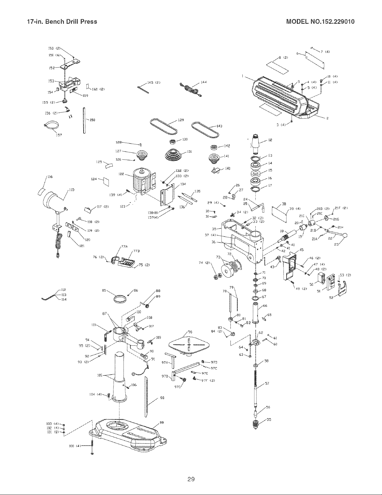
17-in.BenchDrill Press MODELN0.152.229010
Whenservicing,useonUyCRAFTSMANrepUacementparts,Useof anyotherpartsmaycreatea HAZARDor cause
productdamage,
Anyattemptto repairor repUaceelectrbaUpartsonthisdrHUpressmaycreatea HAZARDunbssaquarriedservice
techniciandoesrepairs,RepairserviceisavaHabbatyournearestSearsServiceCenter,
Alwaysorderby PARTNUMBER,notbykeynumber,
KEY PART KEY PART
NO. NO. DESCRIPTION QTY. NO. NO. DESCRiPTiON QTY.
0R92380 Pulley Cover Assy const of, (1,2,3,4,5,6,7,8,9) 1 81 0R92354
1 OR92301 Upper Pulley Cover 1 82 OR92355
2 0R92383 Bottom Pulley Cover 1 83 OR92356
3 0R91774 M4xlOmm Cheese Hd Screw 4 84 0R93531
4 0R90078 M4 Hex Nut 4 85 0R92411
5 0R90431 M4,3 Ext Tooth Washer 4 86 OR93552
8 0R93452 Speed Chart 1 87 OR92412
7 0R93541 M3.Sx9.Smm Pan Hd Tap Screw 4 88 0R92413
8 OR92433 Nameplate 2 89 OR92364
9 0R93842 M4,2x9.Smm Pan Hd Tap Screw 1 90 OR93558
10 0R90241 M6x12mm Cheese Hd Screw 4 91 0R92414
11 0R90059 M6.4 Flat Washer 4 92 0R92367
12 0R92384 Sleeve 1 93 OR92728
13 0R92306 Retaining Ring 1 94 0R92388
14 0R90366 Ball Bearing 6204 1 95 0R92728
15 OR92307 Spacer 1 96 OR92418
16 0R90366 Ball Bearing 6204 1 97A 0R92425
17 0R92306 Retaining Ring 1 97B 0R92421
0R93553 Pinion Assy const of, (18,19,20) 1 97C 0R93559
18 0R92404 Pinion 1 97D OR92422
19 0R92403 Feed Dial 1 97E 0R92419
20 0R93884 MSx45mm Spring Pin 1 97F 0R92420
21A 0R92400 Special Pin 1 97G 0R92424
21B 0R92401 Retaining Split Bushing 1 98 OR92373
21C 0R92402 Handle Support 1 99 0R92374
21D 0R91764 MSxlOmm Hex Soc Set Screw 2 lOO 0R92725
21E 0R93555 Pin 5x26mm 1 101 0R91499
21F 0R93558 M4x12mm Pan Hd Screw 2 102 0R90248
21G 0R92397 Cover Plate 1 103 0R90307
21H 0R92399 Spring 1 104 OR93546
22 0R92398 Handle 1 105 0R92428
23 0R92331 Knob 1 106 OR93524
24 OR93823 Ext Ret Ring 1 107 0R90222
25 0R92330 Tension Handle 1 108 0R92389
28 0R90310 MSx16mm Hex Hd Screw 1 109 OR92370
27 0R92328 Eccentric 1 110 OR92418
28 0R92329 Pin 1 111 0R92388
29 0R92327 Foam Washer 4 112 OR90289
30 0R90382 M5x16mm Cheese Hd Screw 1 113 0R90290
31 0R92324 Clamp 1 114 0R93547
32 OR93524 MlOx12mm Bex Soc Set Screw 2 115 OR92375
33 0R93848 M6x24mm Spring Pin 2 116 0R91317
34 0R92326 Lock Screw 2 117 OR92377
35 0R92398 Headstock incl, (3637,38,39) 1 118 OR91758
36 0R93503 Serial Number Label 1 119 0R90502
37 OR92728 5ram Drive Screw 4 120 0R92376
38 OR92325 Warning Label 1 121 OR92487
39 0R92728 5ram Drive Screw 4 122 0R92390
40 0R90228 MlO Hex Nut 1 123 0R92393
41 0R90647 3/8" Lock Washer 1 124 OR93502
42 0R92335 Special Screw 1 125 0R93501
43 0R92336 Lock Handle 1 126 0R90222
45 OR92406 Switch Box 1 127 OR92388
46 0R90382 MSx16mm Cheese Hd Screw 2 128 0R92312
47 0R90362 M5,3 Ext Tooth Washer 4 129 OR92385
48 0R90507 M5x8rnm Pan Hd Screw 2 130 0R92315
49 OR93543 M5x28mm Pan Hd Screw 2 131 0R92389
50 0R90343 Push Button Switch 1 132 OR90280
51 0R91060 Switch Cover Assy 1 133 0R93539
52 0R91040 Switch Paddle 1 134 0R92317
53 OR93829 M4x2Omm Pan Hd Tap Screw 2 135 OR92391
55 OR92359 Chuck 1 136 0R92392
56 0R92358 Arbor 1 137 OR90307
57 0R92410 Spindle 1 138 OR91499
58 0R93544 Ball Bearing6205 1 139 OR90308
60 0R93833 M6x45mm Hex Hd Screw 1 140 0R92387
61 0R90306 M6x12mm Rex Soc Set Screw 1 141 0R92388
62 0R92350 Stop Collar 1 142 OR90075
63 0R93580 M12 x 1,75 Lock Nut 1 143 OR92385
64 0R90235 M6 Hex Nut 1 144 0R92394
65 0R92349 Spindle Adapter Remover 1 145 OR92322
66 0R92407 Quill 1 0R92428
67 OR92347 Rubber Washer 1
68 0R90218 Ball Bearing 6203 1 150 0R92717
69 OR92346 M17,5 Flat Washer 1 151 0R92718
70 0R92345 Ring 1 152 OR92711
71 0R92344 Nut 1 153 0R92712
72 0R92337 Spring Retainer 1 154 0R92713
73 0R92408 Spring Assy 1 155 0R92715
74 0R93551 M12 x 1,5 Lock Nut 2 156 OR92716
75 0R90381 M5 Hex Nut 2 157 0R92709
76 0R93557 MSx35mm Pan Hd Screw 2 158 0R92710
77A 0R92360 Tool Tray-Back 1 159 OR92714
77B OR92361 Tool Tray-Front 1 160 0R92731
78 0R92408 Depth Rod incl, (79) 1 161 0R90375
79 0R92409 Depth Scale 1 162 0R92429
80 0R92353 Stop Nut Assy incl, (81,82) 1 28
Spring
Quick Release Nut
Mounting Bracket
M6x12mm Flat Hd Screw
Ring
MTxSrnm Hex Soc Set Screw
Table Bracket Assy incl, (88,89,90,91,92,93,94,95)
Shaft
Pinion Gear
8/8-11x1-1/2" Hex Hd Bolt
Lock Pin W/Cabb
Scale
5mm Drive Screw
Indicator
5mm Drive Screw
Table
Sliding Extension Table Assy
Square Tube Support incl, (97C)
M3x3Omm Spring Pin
Insert Cap
Clamp Plate
Lock Screw
Knob
Rack
Base
M8x125mm Hex Hd Screw
M8.4 Fiat Washer
M8.1 Lock Washer
M8 Hex Nut
MlOx4Omm Hex Hd Screw
Cobmn Assy incl, (106)
MlOx12mrn Hex Soc Set Screw
MTxlOmm Hex Soc Set Screw
Handle Assy
Lock Handle Assy-Tabb
Worm Gear
Lock Handle Assy (Column)
2.Smm Hex Wrench
3mm Hex Wrench
5mm Hex Wrench
Light Assy incl, (116)
Light Warning Label
Light Cord Clamp
M6x16mm Hex Soc Hd Screw
MTmm Lock Washer
Cord Clamp
Cord Sleeve
Motor incl, (123,124,125)
Motor Cord
Wiring Diagram 120/240V
Motor Spec Label
MTxlOmm Hex Soc Set Screw
Motor Pulley
I 28.61
Spindle PulleyNut
Spindle Pulley
M12 x 1,75 Flex Nut
1/2" Lock Washer
Motor Bracket
Motor Tension Rod (R.H.)
Motor Tension Rod (L,H.)
M8 Hex Nut
M8,4 Flat Washer
M8x2Omm Hex Hd Screw
Eccentric
Center Pulley
Ball Bearing 8202
Belt (J28,5)
Power Cord
Tie wire
Laser Assy const of,
50.151,152.153,154,155.156,157,158,159,160)
4xi4mm Hex Soc Hd Screw
M3x14rnm Hex Soc Hd Screw
Top Cover
Main Housing
Switch
Holder
Lasermodub Assy
Hose Clamp
Alignment Pin
Door
Laser Warning Label
Padlock Assy (Not Shown)
Owner's Manual (Not Shown)
1
1
1
2
1
1
1
1
1
1
1
1
2
1
2
1
1
1
1
1
1
2
1
1
1
4
8
4
4
4
1
1
1
1
1
1
1
1
1
1
1
1
2
2
2
1
1
1
1
1
1
1
1
1
1
1
1
2
2
1
1
1
4
8
4
1
1
2
1
1
2
1
2
6
1
1
1
2
2
1
1
1
2
1
1
17-in. Bench Drill Press MODEL N0.152.229010
{50 (2_.
151 (6)_
158--_
#
155 (2)_
_g I_158
45 (2)
119 (2)
/141
_/ 140
_5 (4) i
112
114
103 (4}_
102 (4)_
i01 {g)_
-%
\49 (2)
52 /
29

30

_n
®
_ I 0 N A L_
3/4 Cabaiios de Fuerza (servicio continuo)
1-1/2 Cabalios de Fuerza (ma×imo desarroiiado)
16 Velocidades, Poiea Escalonada
Gama de VeNocidades de Perforacidn
215-2720 R.P.M
Modelo No.
152.229010
C S
PARA SU SEGURJDAD PERSONAL, Reay
obedezca todas Uaslnstrucciones de
Seguddad y Operaci6n antes de operar
esta Taladradora de Banco
Linea de Ayuda al CLiente
1-800-897-7709
Sirvase tenor listo su
No. de Modelo y No. de Sede
Sears, Roebuck and Co., Hoffman Estates, JL 60179 U.S.A.
No. de Pieza OR93513
31
SECO[ON PAG[NA
Garant_a.........................................................................................................................................................................32
Especificacionesde[producto....................................................................................................................................33
[nstruccionesde seguridad.........................................................................................................................................34
Directricespara[ase×tensiones e[_ctricas ............................................................................................................... 35
[nstrucciones de cone×i6n a tierra ............................................................................................................................. 36
[nstrucciones de seguridad especfficas .................................................................................................................... 37
Accesorios y aditamentos ........................................................................................................................................... 38
Conozca su m&quina .................................................................................................................................................. 39
Contenido de [a caja .................................................................................................................................................... 40
[nstrucciones de montaje ............................................................................................................................................ 42
Operaciones y aiuste ................................................................................................................................................... 47
Mantenimiento .............................................................................................................................................................. 56
Guia de [oca[izaci6n de averias .................................................................................................................................. 57
Listado de piezas .......................................................................................................................................................... 58
[nformaci6n de $ervicio .......................................................................................................................... Contraportada
GARANTiA COMPLETA DE UN ANO PARA LAS HERRAMIENTAS CRAFTSMAN
Siesta herramienta Craftsman Ibgase a failar debido a defectos materiabs o de elaboraci6n dentro de un aho a partir de la
fecha de compra, LLAME AL 1-800-4-MY*HQME @ (en EE,UU,) PARA CQQRDINAR LA REPARACION GRATUITA,
Si se utiliza esta herramienta con fines comereiaies o de alquiler, esta garant[a se aplicara por s6io noventa d[as a partir de la
fecha de compra,
Esta 9arantfa se apliea s61o mientras que esta herramienta se encuentre en los Estados Unidos,
Esta garantfa le concede derechos bgabs espeeifieos, y tambien podrb_ tenet otros derechos que var[an de un estado al otto,
Sears Roebuck and Co, Dept 817 WA, Hoffman Estates, iL 60179
32
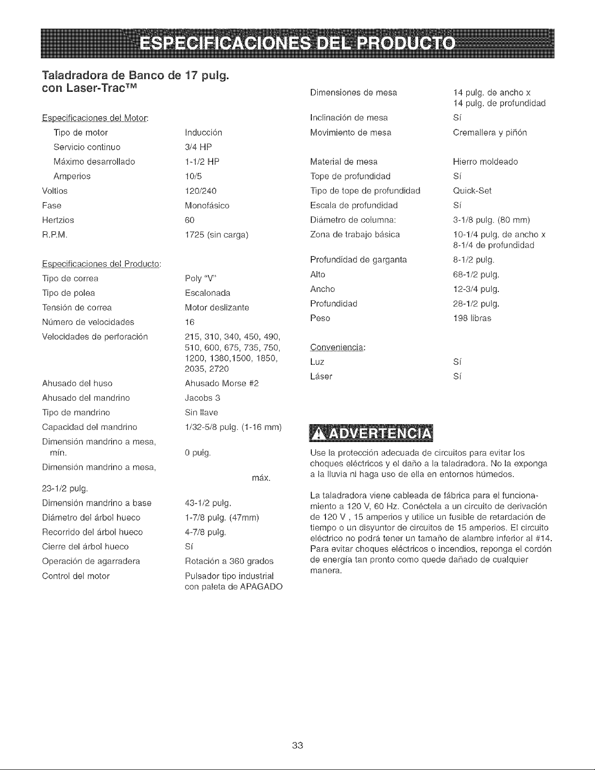
Ta[adradora de Banco de 17 pu[g°
con Laser°Trac TM
_ecificaciones deI Motor:
Tipo de motor Inducci6n
Servicio continuo 3/4 HP
Maximo desarrollado 1-1/2 HP
Amperios 10/5
Voltios 120/240
Fase Monofasico
Hertzios 60
R.RM. 1725 (sin carga)
_ecificaciones deI Producto:
Tipo de correa
Tipo de poIea
Tensi6n de correa
NOmero de velocidades
Velocidades de perforad6n
Ahusado del huso
Ahusado del mandrino
Tipo de mandrino
Capacidad del mandrino
Dimensi6n mandrino a mesa,
mfn.
Dimensi6n mandrino a mesa,
23-1/2 pulg.
Dimensi6n mandrino a base
Diametro deI 9rboJ hueco
Recorrido del arbol hueco
Cierre deI arboI hueco
Operaci6n de agarradera
Control de[ motor
Poly "V"
Escalonada
Motor desJizante
16
215, 310, 340, 450, 490,
510, 600, 675, 735,750,
1200, 1380,1500, 1850,
2035, 2720
Ahusado Morse #2
Jacobs 3
Sin Ilave
1/32-5/8 pulg. (1-16 ram)
0 pulg.
max.
43-1/2 puig.
1-7/8 pulg. (47ram)
4-7/8 pulg.
Si
Rotaci6n a 360 grados
Pulsador tipo industrial
con paleta de APAGADO
Dimensiones de mesa
IncJinaci6n de mesa
Movimiento de mesa
14 pulg. de ancho x
14 pulg. de profundidad
Sf
Cremalbra y pih6n
Material de mesa
Tope de profundidad
Tipo de tope de profundidad
Escab de profundidad
Diametro de coIumna:
Zona de trabajo basica
Profundidad de garganta
Alto
Ancho
Profundidad
Peso
Hierro moldeado
Sf
Quick-Set
Sf
3-1/8 pulg. (80 ram)
10-1/4 pulg. de ancho x
8-1/4 de profundidad
8-1/2 putg.
68-1/2 pulg.
12-3/4 pulg.
28-1/2 pulg.
198 libras
Conveniencia:
Luz S[
Laser S[
Use la protecci6n adecuada de circuitos para evitar los
choques etectricos y et daffo a la taladradora. No Ia exponga
a la Iluvia ni haga uso de ella en entomos h0medos.
La taladradora viene cabbada de fabrica para el funciona-
miento a 120 V, 60 Hz. Con6cteb a un circuito de derivaci6n
de 120 V, 15 amperios y utilice un fusible de retardaci6n de
tiempo o un disyuntor de circuitos de 15 amperios. Ei circuito
el6ctrico no podr_, tener un tamaho de abmbre inferior al #14.
Para evitar choques el6ctricos o incendios, reponga el cord6n
de energia tan pronto como quede dahado de cualquier
manera.
33
INSTRUCCIONES GENERALES
DE SEGURIDAD
El uso de una taIadradora puede ser peligroso si se hace
caso cruise de la seguridad y el sentido comon. El operario
debe estar famifiarizado con et funcionamiento de esta herra-
mienta. Lea este manual para entender esta taladradora. NO
OPERE esta taladradora si no entiende plenamente las Iimita-
ciones de esta herramienta. NO MODIFIQUE este taIadradora
de ninguna manera. REOUERDE: Su seguridad personal es
su responsabiiidad.
ANTES DE HACER USO
DE LA TALADRADORA
Lea y obedezca todas las instrucciones de Seguridad y
Operaci6n antes de operar la taladradora para evitar hendas
graves y daRo a la herramienta.
1. LEA el Manual de Instrucciones cabalmente. APRENDA
como usar la herramienta para su aplicaci6n propuesta.
2. UTILICE PROTECCION OCULAR SlEMPRE. Cualquier
herramienta mecanica puede expuIsar escombros hacia
los ojos durante Ias operaciones, causando daRo ocular
grave y permanente. Los anteojos de use cotidiano NO
son gafas de seguridad. Utiiice gafas de seguridad (que
cumplan con la normativa Z87.1 de ANSb StEMPRE
cuando vaya a operar herramientas mec_inicas. Las
gafas de seguridad estg,n disponibles en las tiendas de
Ventas al Detal de Sears.
3. UTILICE PROTECCION AUDmVA SlE_,_PRE. El algo-
d6n por sf solo no constituye un dispositivo de protecci6n
aceptable. El equipo auditNo debe eumplir con las
normativas S3.19 de ANSI.
4. UTJUCE SlEMPRE UNA CARETA CONTRA EL POLVO
PARA EVITAR ASPIRAR POLVOS PEUGROSOS O
PART_CULAS EN EL AtRE, incluyende polvo de madera,
pelvo de sflice cdstalino y polvo de asbesto. Didja las
partfcuias en direcci6n opuesta a! rostro y ei cuerpo.
Opere la herramienta siempre en una zona bien ventilada
y proporcione Ia remoci6n apropiada de! polvo. UtiIice un
sistema de recolecci6n de polvo siempre que sea posF
ble. La exposici6n al polvo puede ocasionar dares respi-
ratodos graves y permanentes u otras heridas, inciuyen-
do silicosis (una enfermedad pulmonar grave), cancer y
la muerte. Evite aspirar el polvo y evite e! contacto pro-
Iongado con el polvo. El permitir Ia entrada deI polvo en
su boca u oios, o deiar que permanezca sobre su pieI,
puede promover la absorci6n de material daRino. Utilice
protecci6n respiratoria aprobada per NIOSH/OSHA, de
ajuste correcto y apropiada para la exposici6n ai polvo, y
lave Ias zonas expuestas con iab6n y agua.
5. Mantenga Ia zona de trabaio limpia, bien iIuminada y
organizada EN TODO MOMENTO. NO trabaje en un
entomo con superficies de piso resbalosas debido a los
escombros, grasas y cera.
6. Desenchufe la herramienta del tomacorrientes SIEMPRE
que vaya a reaiizar cuaIquier ajuste, recambio de piezas
o Ilevar a cabo cuatquier tarea de mantenimiento.
34
7. EVITE LOS ARRANQUES ACCIDENTALES. Aseg0rese
de que el interrupter de energ[a se encuentre en la posi-
ci6n de "OFF" (apagado) antes de enchufar el cord6n de
potencia y causar dare a la herramienta.
8. EVITE UN ENTORNO DE TRABAJO PEUGROSO. NO
utilice Ias herramientas electricas en entornos h0medos
ni las exponga a la Iluvia.
9. HAGA SU TALLER A PRUEBA DE NINOS al quitar las
Ilaves de los interruptores, desenchufando Ias herramien-
tas de sus tomacorrientes y usando candados.
10. NO utilice herramientas electricas en la presencia de
I[quidos o gases inflamables.
11. NO FUERCE LA HERRAMiENTA a realizar una
operaci6n para la que no fue diseRada. Realizarb, un
trabajo m_s seguro y de mayor calidad s61o efectuando
aqueilas operaciones para las que fue diseRada.
12.
13.
14.
15.
NO se pare sobre la herramienta. Esto podrfa resultar en
heridas graves si la herramienta se vuelca o si usted
hace contacto accidental con la herramienta.
NO almacene nada sobre o cerca de Ia herramienta
deride alguien pueda intentar pararse sobre la herra-
mienta para alcanzarto.
NO opere la herramienta si se encuentra bajo la infiuen-
cia del alcohol o de las drogas.
EN TODA Y CADA OCAS_0N, REVISE SJ EXtSTEN
PIEZAS DANADAS ANTES DE OPERAR LA HERRA-
MIENTA. Revise todos los protectores cuidadosamente
para asegurarse de que funcionen correctamente, que no
esten daRados, y que realicen sus funciones destinadas.
Revise la alineaci6n y busque Ia atascadura o ruptura de
todas las piezas en movimiento. Un protector, una pieza
de inserci6n u otra pieza daRada debe repararse y susti-
tuirse inmediatamente.
16. CONECTE TODAS LAS HERRAMIENTAS A TIERRA.
Si Ia herramienta viene equipada con un enchufe de tres
roaches, se Ie debe enchufar en un tomacorrientes de
tres contactos. El tercer macho se utiliza para conectar la
herramienta a tierra y ofrecer protecci6n contra !os
cheques electricos accidentales. NO quite ei tercer
macho. Ver Instrucciones de Conexi6n a Tierra.
17. MANTENGA ALEJADOS A LOS VISITANTES Y NtNOS
de la taladradora. NO permita que haya gente en la zona
inmediata de trabajo, sobre todo cuando Ia herramienta
electrica se encuentre en funcionamiento.
18.
19.
20.
MANTENGA TODOS LOS PROTECTORES EN SUS
SITIOS Y EN BUENAS CONDICIONES DE TRABAJO.
MANTENGA SU EQUILIBRIO, NO se extienda sobre la
herramienta. Utilice calzado con suetas de caucho y
resistentes al aceite. Mantenga el piso despejado de
escombros, grasas o cera.
MANTENGA SUS HERRAMIENTAS CON CUIDADO.
Mantenga sus herramientas limpias yen buen estado de
funcionamiento siempre. Mantenga filosas todas las
hoias y las brocas.
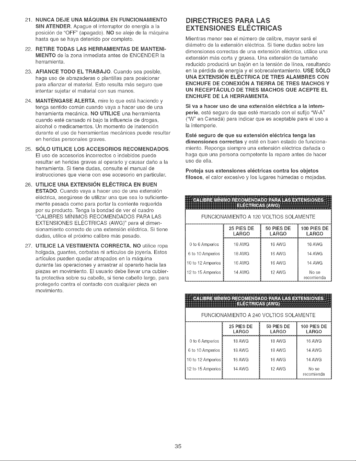
21.NUNCADEJEUNAM_,QU_NAENFUNCJONAM_ENTO
SiNATENDERApagueelinterrupterdeenerg[aaIa
posici6nde"OFF"(apagado).NOsealejedeJamb,quina
hastaquesehayadetenidopercompbto.
22.RETIRETODASLASHERRAMJENTASDEMANTEN_-
M_ENTOdeIazonainmediataantesdeENCENDERla
herramienta.
23.AFJANCETODOELTRABAJO.Cuandoseaposible,
hagausedeabrazaderasopJantilbsparaposicionar
paraafianzareEmateriakEstoresuitam_.sseguroque
intentarsqetarelmaterialconsusmanes.
24.MANT¢:NGASEALERTA,mireIoqueestahaciendoy
tengasentidocomuncuandovayaa hacerusedeuna
herramientamecanica.NOUT_UOEunaherramienta
cuandoestecansadonibajoIaJnfiuenciadedrogas,
alcoho!o medicamentos.Unmementodeinatenci6n
duranteetusedeherramientasmecb,nicaspuederesultar
enheridaspersonabsgraves.
25.SOLOUTJLJCELOSACCESOR_OSRECOMENDADOS.
Etusodeaccesoriosincorrectosoindebidospuede
resultarenheridasgravesaIoperarioycausardafioala
herramienta.SJtienedudas,consulteelmanualde
instruccionesquevieneconeseaccesorioenparticular.
26.UTIUCEUNAEXTENSKSNEL¢:CTRJCAENBUEN
ESTADQCuandovayaahacerusodeunaextensi6n
el6ctrica,aseguresedeutilizarunaqueseaIosuficiente-
mentepesadacomoparaportarIacorrienterequerida
persuproducto.TengalabondaddevereJcuadro
"CALIBRESM[NIMOSRECOMENDADOSPARALAS
EXTENSIONESELE_CTRICAS(AWG)"paraeldimen-
sionamientocorrectodeunaextensi6nelectrica.Sitiene
dudas,utiliceel pr6ximocalibremaspesado.
27.UTJLJCELAVESTJMENTACORRECTA.NOutiliceropa
holgada,guantes,corbatasniartfcu!osdejoyerfa.Estos
artfculospuedenquedaratrapadosenlamaquina
duranteIasoperacionesyarrastraraloperariohaciaIas
piezasenmovimiento.ElusuariodebeIlevarunacubier-
taprotectivasobresucabelIo,sitienecabellolargo,para
proteger!ocontraelcontactoconcuaJquierpiezaen
movimiento.
DIRECTRJCES PARA LAS
EXTENSUONES ELECTRICAS
Mientras menor sea el n0mero de calibre, mayor sera el
diametro de la extensi6n electrica. Si tiene dudas sobre las
dimensiones correctas de una extensi6n electrica, utilice una
extensi6n mas corta y gruesa. Una extensi6n de tama_o
reducido producira un baj6n en Ia tensi6n de linea, resultando
en la perdida de energ!a y el sobrecalentamiento. USE SOLO
UNA EXTENSION ELECTR_OA DE TRES ALAMBRES CON
ENCHUFE DE CONEX_6N A TJERRA DE TRES MACHOS Y
UN RECEPTACULO DE TRES MACHOS QUE ACEPTE EL
ENCHUFE DE LA HERRAM_ENTA.
Siva ahacer uso de aria e×tension eBectrica ama intemo
perie, este seguro de que este marcado con el sufijo "W-A"
("W" en Canadb,) para indicar que es aceptable para el use a
Ja intemperie.
Est_ seguro de que su e×tensi6n em_ctrica tenga mas
dimensiones correctas y este en buen estado de funciona-
miento. Reponga siempre una extensJ6n el6ctrica daSada o
haga que una persona competente Ja repare antes de hacer
use de ella.
Proteja sus extensiones em_ctricae contra los objetos
fHosos, el caJor excesivo y los Jugares hOmedas o mojadas.
FUNCIONAMIENTO A 120 VOLTIOS SOLAMENTE
0 to 6 Amperios
6 to !0 Amperios
10 to 12 Amperios
12 to 15 Amperios
25 PIES DE
LARGO
18 AWG
18 AWG
16 AWG
14 AWG
50 PIES DE
LARGO
16 AWG
16 AWG
16 AWG
12 AWG
100 PINESDE
LARGO
16 AWG
14 AWG
14 AWG
No se
recomienda
FUNCIONAMIENTO A 240 VOLTIOS SOLAMENTE
0 to 6 Amperios
6 to 10 Amperios
10 to 12 Amperios
12 to 15 Amperios
25 PIES DE
LARGO
18AWG
18 AWG
16 AWG
14 AWG
50 PIES DE
LARGO
18 AWG
18 AWG
16 AWG
12 AWG
100 PIES DE
LARGO
16 AWG
14 AWG
14 AWG
No se
recomienda
35
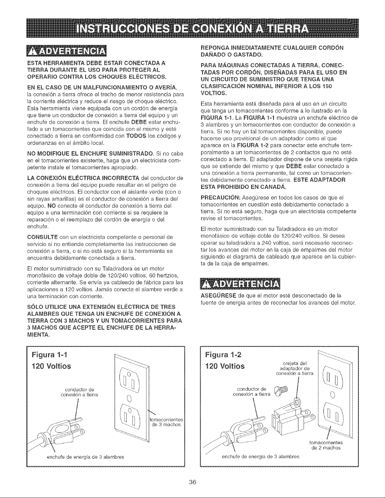
ESTA HERRAM_ENTA DEBE ESTAR CONECTADA A
TIERRA DURANTE EL USO PARA PROTEGER AL
OPERAR_O CONTRA LOS CHOQUES ELECTR_COS.
EN EL CASO DE UN MALFUNCJONAMJENTO O AVERJA,
Jaconexi6n a tJerra ofrece eJ trecho de menor resistencia para
Jacorriente electrica y reduce el riesgo de choque el6ctrico.
Esta herramienta viene equipada con un cord6n de energ[a
que tiene un conductor de conexi6n a tierra del equipo y un
enchufe de conexi6n a tierra. El enchufe DEBE estar enchu-
fado a un tomacorrientes que coincida con el mismo y este
conectado a tierra en conformidad con TODOS los c6digos y
ordenanzas en el _4mbito local.
NO MODJFJQUE EL ENCHUFE SUMINJSTRADO. Si no cabe
en el tomacorrientes existente, haga que un eJectricista com-
petente instale el tomacorrientes apropiado_
LA CONEXION ELEOTRJOA _NCORREOTA del conductor de
conexi6n a tierra deI equipo puede resultar en e! peligro de
choques electricos. El conductor con el aislante verde (con o
sin rayas amarillas) es el conductor de conexi6n a tierra deJ
equipo. NO conecte el conductor de conexi6n a tierra del
equipo a una terminaci6n con corriente si se requJere Ia
reparaci6n o el reemplazo del cord6n de energ[a o deJ
enchufe.
CONSULTE con un electricista competente o personat de
servicio si no entiende completamente las instrucciones de
conexi6n a tierra, o si no esta seguro si la herramienta se
encuentra debidamente conectada a tierra.
El motor suministrado con su Taladradora es un motor
monofasico de voltaje doble de 120/240 voltios, 60 hertzios,
corriente alternante. Se env[a ya cableado de f#,brica para las
aplicaciones a 120 voJtios. Jamb,s conecte el alambre verde a
una terminaci6n con corriente.
SOLO UT_L_CE UNA EXTENSJ0N ELE_CTRJCA DE TRES
ALAMBRES QUE TENGA UN ENCHUFE DE CONEXION A
TIERRA CON 3 MACHOS Y UN TOMACORR_ENTES PARA
3 MACHOS QUE ACEPTE EL ENCNUFE DE LA NERRA-
MIENTA.
REPONGA _NMEDJATAMENTE CUALQUJER CORDON
DANADO O GASTADO.
PARA MAQUINAS CONECTADAS A TJERRA, CONEC-
TADAS POR CORDON, DJSENADAS PARA EL USO EN
UN CIRCUJTO DE SUM_N_STRO QUE TENGA UNA
CLASJFJCAC_0N NOMINAL _NFERJOR A LOS 150
VOLTIOS,
Esta herramienta esta dise[iada para el uso en un circuito
que tenga un tomacorrientes conforme a Io ilustrado en la
FIGURA 1-1. La FIGURA 1-1 muestra un enchufe el6ctrico de
3 alambres y un tomacorrientes con conductor de conexi6n a
tierra. Si no hay un tal tomacorrientes disponible, puede
hacerse uso provisional de un adaptador como el que
aparece en Ia FIGURA 1-2 para conectar este enchufe tem-
poralmente a un tomacorrientes de 2 contactos que no este
conectado a tierra. EI adaptador dispone de una orejeta rigida
que se extiende del mismo y que DEBE estar conectado a
una conexi6n a tierra permanente, taI como un tomacorrien-
tes debidamente conectado a tierra. ESTE ADAPTADOR
ESTA PROHIBIDO EN CANAD._.
PRECAUCION: Aseg0rese en todos los casos de que el
tomacorrientes en cuesti6n este debidamente conectado a
tierra. Si no est_ seguro, haga que un eJectricista competente
revise el tomacorrientes.
El motor suministrado con su Taladradora es un motor
monof_sico de voJtaje doble de 120/240 voltios. Si desea
operar su taladradora a 240 voJtios, serb, necesario reconec-
tar tos avances del motor en la caja de empatmes det motor
siguiendo el diagrama de cabJeado que aparece en la cubier-
ta de Jacaja de empalmes.
ASEGURESE de que el motor este desconectado de la
fuente de energfa antes de reconectar Jos avances del motor.
Figura 1-1
120 Vo_tios
conductor de
conexi6n a tierra
enchufe de energia de 3 alambres
tomacordentes
de 3 machos
Figura 1-2
120 Vo_tios oreieta del
adaptador de
conexi6n a tierra
conductor de (_)
conexi6n a tierra
tomacorrientes
de 2 machos
enchufe de energia de 3 alambres
36
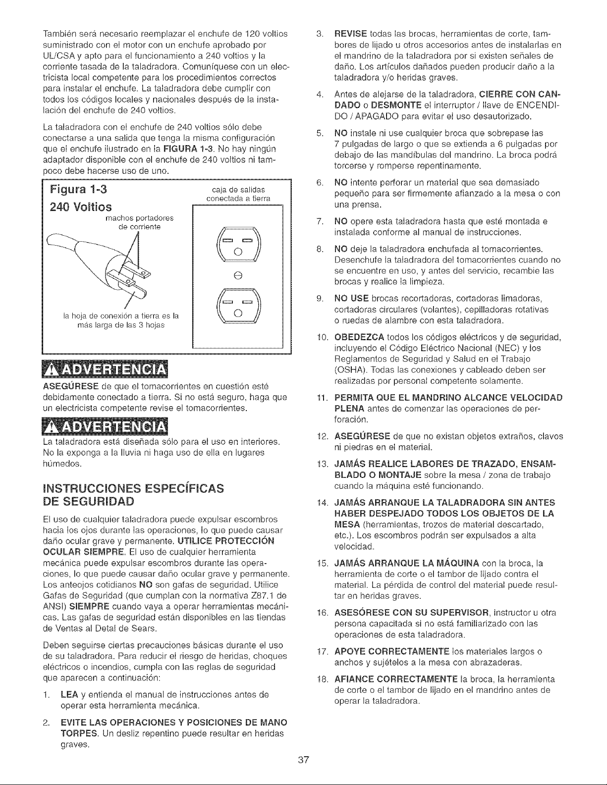
Tambien sera necesario reemplazar el enchufe de 120 voltios
suministrado con el motor con un enchufe aprobado por
UL/CSA y apto para el funcbnamiento a 240 voltios y la
corriente tasada de la taladradora. Comunfquese con un ebc-
tricista IocaJ competente para los procedimientos correctos
para instaJar e! enchufe. La taJadradora debe cumpHir con
todos Hosc6digos locales y nacionaJes despues de la insta-
Jaci6n del enchufe de 240 voHtios.
La taHadradora con el enchufe de 240 voltJos s61o debe
conectarse a una saiHda que tenga la misma configuraci6n
que el enchufe ilustrado en Ia FJGURA 1-3. No hay ningOn
adaptador disponibb con el enchufe de 240 voJtios ni tam-
_oco debe hacerse uso de uno.
Figura 1-3
240 Voltios
machos portadores
de corriente
caja de salidas
conectada a tierra
la hoja de conexi6n a fierra es la
mas larga de las 3 hoias
(9
ASEGURESE de que eJtomacorfientes en cuesti6n este
debidamente conectado a tierra. Si no esta seguro, haga que
un electricista competente revise el tomacorrientes.
La taHadradora esta diseFiada s61o para el uso en interiores.
No la exponga a la Iluvia ni haga uso de ella en Jugares
hOmedos.
INSTRUCCIONES ESPECJFICAS
DE SEGURJDAD
El uso de cualquier taJadradora puede expulsar escombros
hacia Hosojos durante Hasoperaciones, Hoque puede causar
daF_oocutar grave y permanente. UTIUCE PROTEOCtON
OCULAR SJEMPRE. El uso de cuaJquier herramienta
mecanica puede expulsar escombros durante Hasopera-
ciones, Io que puede causar daBo ocular grave y permanente.
Los anteojos cotidianos NO son gafas de seguridad. UtiHice
Gafas de Seguridad (que cumplan con la normativa Z87.1 de
ANSH) SlEMPRE cuando vaya a operar herramientas mecani-
cas. Las gafas de seguridad estan disponibles en Jastiendas
de Ventas al Detal de Sears.
Deben seguirse ciertas precauciones bgsicas durante el uso
de su taladradora. Para reducir el riesgo de heridas, choques
electricos o incendios, cumpia con las reglas de seguridad
que aparecen a continuaci6n:
1. LEA y entienda el manual de instrucciones antes de
operar esta herramienta mecb_nica.
2. EVITE LAS OPERACIONES YPOSICIONES DE MANO
TORPES. Un desHiz repentino puede resuHtar en hefidas
graves.
7.
8.
3. REVISE todas Ias brocas, herramientas de corte, tam-
bores de lijado u otros accesorios antes de instalarJas en
el mandrino de la taladradora por si existen seFiales de
da5o. Los artfculos daF_ados pueden producir daho a la
taladradora y/o heridas graves.
4. Antes de aJejarse de la taladradora, CIERRE CON CAN-
DADO o DESMONTE el interruptor /Ilave de ENCENDF
DO /APAGADO para evitar el uso desautorizado.
5. NO instale ni use cuaJquier broca que sobrepase Ias
7 pulgadas de largo o que se extienda a 6 pulgadas por
debajo de las mandfbulas del mandrino. La broca podra
torcerse y romperse repentinamente.
6. NO intente perforar un material que sea demasiado
peque5o para ser firmemente afianzado a la mesa o con
una prensa.
NO opere esta taladradora hasta que este montada e
instalada conforme al manual de instrucciones.
37
g.
NO deje HataHadradora enchufada at tomacorrientes.
Desenchufe la taladradora det tomacorrientes cuando no
se encuentre en uso, y antes del servicio, recambie las
brocas y realice Ia limpieza.
NO USE brocas recortadoras, cortadoras Iimadoras,
cortadoras circulares (volantes), cepilIadoras rotativas
o ruedas de alambre con esta taladradora.
10. OBEDEZCA todos Hosc6digos eHectricos y de seguridad,
incluyendo et C6digo EJectrico Nacional (NEC) y Hos
Reglamentos de Seguridad y SaJud en el Trabajo
(OSHA). Todas las conexiones y cabbado deben ser
reaHizadas por personal competente solamente.
11. PERMITA QUE EL MANDRJNO ALCANCE VELOCJDAD
PLENA antes de comenzar Jas operaciones de per-
foraci6n.
12. ASEGURESE de que no existan objetos extrafios, clavos
ni piedras en el material
13. JAM,_S REALICE LABORES DE TRAZADO, ENSAMo
BLADO O MONTAJE sobre Ia mesa / zona de trabajo
cuando la maquina este funcionando.
14. JAM,_,S ARRANQUE LA TALADRADORA SiN ANTES
HABER DESPEJADO TODOS LOS OBJETOS DE LA
MESA (herramientas, trozos de material descartado,
etc.). Los escombros podran ser expulsados a alta
velocidad.
15. JAMAS ARRANQUE LA MAQUJNA con la broca, la
herramienta de corte o el tambor de Hijado contra el
material La perdida de control del material puede resuI-
tar en heridas graves.
16. ASESORESE CON SU SUPERWSOR, instructor u otra
persona capacitada si no esta familiarizado con las
operaciones de esta taladradora.
17. APOYE CORRECTAMENTE los materiaJes largos o
anchos y suj6telos a Ja mesa con abrazaderas.
l& AFIANCE CORRECTAMENTE la broca, Ia herramienta
de corte o el tambor de Jijado en eJ mandrino antes de
operar la taladradora.
19.REPONGAcualquiercord6ndaBadoinmediatamente.
NOutiliceuncord6no enchufedaRado.SiIataJadradora
nofuncionacorrectamente,osisehadaRado,deiadoa
laintemperieo entradoencontactoconagua,devueJvala
auncentredeservicioSears.
20.AFJANCElataladradoraalsuelooaunbancodetraba-
jo.Lasvibracionespuedenhacerquelamaquinase
deslice,camineosevuelque.
21.AFIANCEel materialfirmementecontralamesa.No
intenteperforarunmaterialquenotengaunasuperficie
planacontralamesa,o quenoesteafianzadaconun
tornilIodebanco.ImpidaqueeImaterialgireabraz_'mdolo
alamesaoafianzandolocontraIacotumnadeIaprensa.
LaperdidadecontrolsobreeJmaterialpuederesultaren
heridasgraves.
22.ENCLAVEelapoyodeicabezaly delamesaa Jacotum-
nafirmemente,ylamesaalapoyodeJamesa,antesde
operarIataladradora.
23.LataladradoraestadiseBadaparaelusedomesticooel
usecomerciaJligeroSOLAMENTE.
24.PARAREDUCERELPEUGRODELOSCNOQUES
EL¢:CTRICOS,nouseJaherramientaa laintemperie=No
laexpongaalaIluvia=Almacenelabajotecho=
25=APAGUELATALADRADORAydesench0feladela
fuentedeenergfa.Espereaquelabroca,herramientade
corteotambordelijadodejendegirarantesdelimpiarIa
mesa/zonadetrabajo,retiraroasegurarelmaterial,o
cambiarelmontaje.
26.USEs61obrocas,herramientascortantes,tamboresde
lijadouotrosaccesoriosconeltamaRodeespiga
recomendadaenestemanualdeservicio.Eiaccesorio
detamaRoincorrectopuedeocasionardarealatala-
dradoray/oheridasgraves.
27.SOLOutiliceestamaquinadeacuerdoconestemanual
deinstrucciones.SOLOutiiicelosaccesoriosrecomen-
dadosperSears.
28.UTJLICE LAS VELOCIDADES REOOMENDADAS para
todas las operaciones= Otras vetocidades podrAn causar
el malfuncionamiento de la maquina, causando daBo a la
taladradora y/o heridas graves.
29.
30.
INFORMACl0N ADJCIONAL acerca dei funcionamiento
seguro y correcto de este producto esta disponibb de
parte de las siguientes fuentes:
Power Tools Institute
1300 Summer Avenue
Cleveland OH 44115-2851
Nationa! Safety Council,
1121 Spring Lake Drive
Itasca, IL 60143-3201
American National Standards Institute
25 West 43 rd Street 4th floor
New York, NY 10036
ANSI 01.1, Requisites de Seguridad para
Maquinas de Ebanisterfa, y los reglamentos
del Departamento del Trabajo de los EE,UU,
GUARDE ESTAS tNSTRUCCIONES. Refierase a elias
frecuentemente y utiliceJas para capacitar a otros
usuarios.
REGLAS ADJCIONALES DE SEGURJDAD
PARA EL L_,SER
1= LUZ LASER = NO MIRE EL HAZ, LA APERTURA ni
tampoco el refieio de una superficie espeiada.
2. EVITE LA EXPOSICION = LA LUZ LASER SE EMITE
DESDE AMBOS LADOS DEL ENSAMBLADO DEL
LASER= El uso de controles o ajustes o Ia realizaci6n de
procedimientos ajenos a los especificados aqu[ pueden
resultar en una exposJci6n azarosa a Ja Juz laser=
3= NO DESMONTE EL MODULO LASER. El laser es un
PRODUCTO LASER CLASE H capaz de emitir potencia
laser hasta 1 mW MAX= a 635 ram, Jo que puede resultar
en exposici6n si se desmantela el m6dulo= La unidad
laser cumpb con 21 CFR 1040=10 y 1040=11=
4= EL USO DE CONTROLES OAJUSTES O LA
REALIZACION DE PROCEDIM_ENTOS AJENOS A LOS
ESPEClFICADOS AQUi PUEDEN RESULTAR EN UNA
EXPOSICION AZAROSA A LA RADJACJON.
ACCESORJOS DISPONIBLES
Visite su Departamento de Ferreteffa Sears o consuIte el
CataJogo de Herramientas Manuales y Mecanicas de
Craftsman para los siguientes accesorios:
ART_CULO NO. DE EXISTENCJA
*Cortadora de Circulos 25293
*Estuche de Abrazaderas 26426
*Tornillo de Banco de 8 puIg. 24077
*Tornillo de Banco de 4 puig. 24081
*Tornillo de Banco de 3 puig. 24071
*Estuche de Tambor de Liiado de 21 piezas 25262
*Conjunto de Brocas Forstner de 7 piezas 25389
Sears podra recomendar otros accesorios que no estan fista-
dos en este manual.
Consulte con su Departamento de Ferreter[a Sears mAs cer-
cano o su Catalogo de Herramientas Manuabs y Mecanicas
de Craftsman para otros accesofios.
No haga uso de ning0n accesorio a menos que haya Ie[do
cabalmente el Manual de Instrucciones para dicho accesorio.
S61o utiJice accesorios recomendados para esta taladradora.
EI uso de cualquier otro accesorio podra ocasionar heridas
graves y producir dare Jataladradora.
38
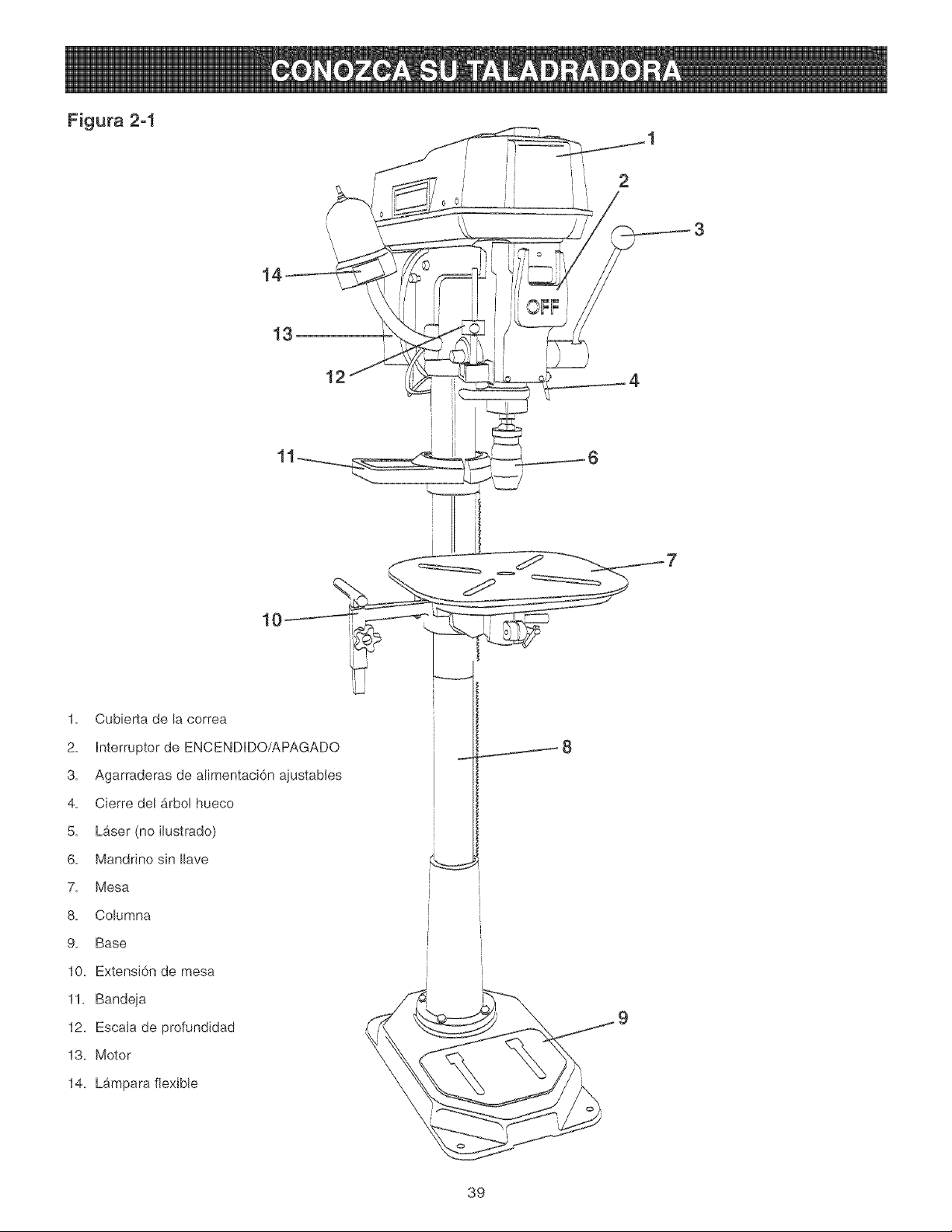
Figura 2-1
i II
12
1. Cubierta de la correa
2. hterruptor de ENCENDIDO/APAGADO
3. Agarraderas de alimentaci6n ajustables
4. Cierre del Arbol hueco
5. LAser (no ilustrado)
6. Mandrino sin Ilave
7. Mesa
8. Columna
9. Base
10. Extensi6n de mesa
11. Bandeia
12. EscaJa de profundidad
13. Motor
14. Lampara flexible
39
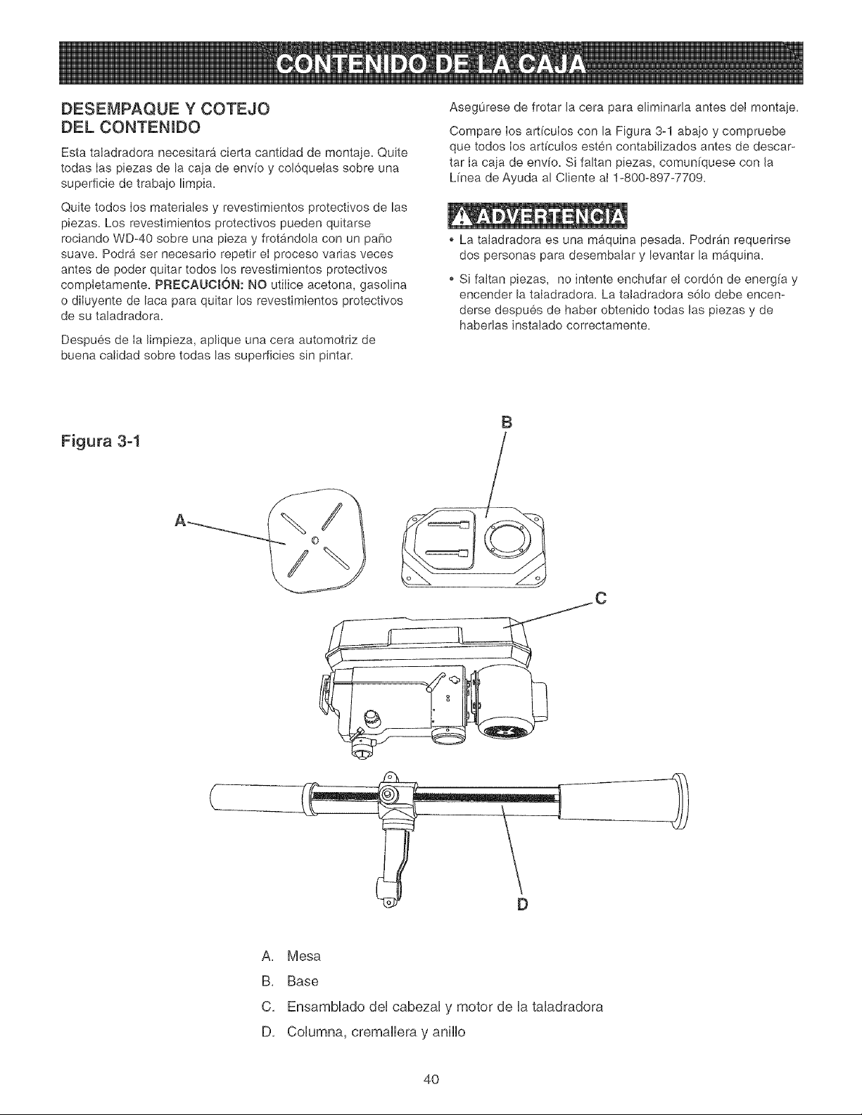
DESEMPAQUE Y COTEJO
DEL CONTENIDO
Esta taladradora necesitara cierta cantidad de montaje. Quite
todas Ias piezas de la caja de env[o y col6queias sobre una
superficie de trabajo limpia.
Quite todos Ios materiales y revestimientos protectivos de las
piezas. Los revestimientos protectivos pueden quitarse
rociando WD-40 sobre una pieza y frotandola con un paho
suave. Podra ser necesario repetir eI proceso varias veces
antes de poder quitar todos los revestimientos protectivos
completamente. PREOAUCION: NO utiIice acetona, gasolina
o diIuyente de laca para quitar los revestimientos protectivos
de su taladradora.
Despues de Ia limpieza, aplique una cera automotriz de
buena calidad sobre todas las superficies sin pintar.
Asegurese de frotar la cera para eliminada antes dei montaje.
Compare los art[culos con la Figura 3-1 abajo y compruebe
que todos los art[culos esten contabilizados antes de descar-
tar Ia caja de envio. Si faltan piezas, comun[quese con la
L[nea de Ayuda al Cliente aI 1-800-897-7709.
La taladradora es una maquina pesada. Podrb_n requerirse
dos personas para desembaJar y levantar la m_.quina.
o Si fakan piezas, no intente enchufar el cord6n de energ[a y
encender la taIadradora. La tatadradora s6!o debe encen-
derse despues de haber obtenido todas las piezas y de
habedas instatado correctamente.
Figura 3-1
B
D
A, Mesa
B, Base
C, Ensamblado del cabezal y motor de la taladradora
D, Columna, cremallera y anillo
4O
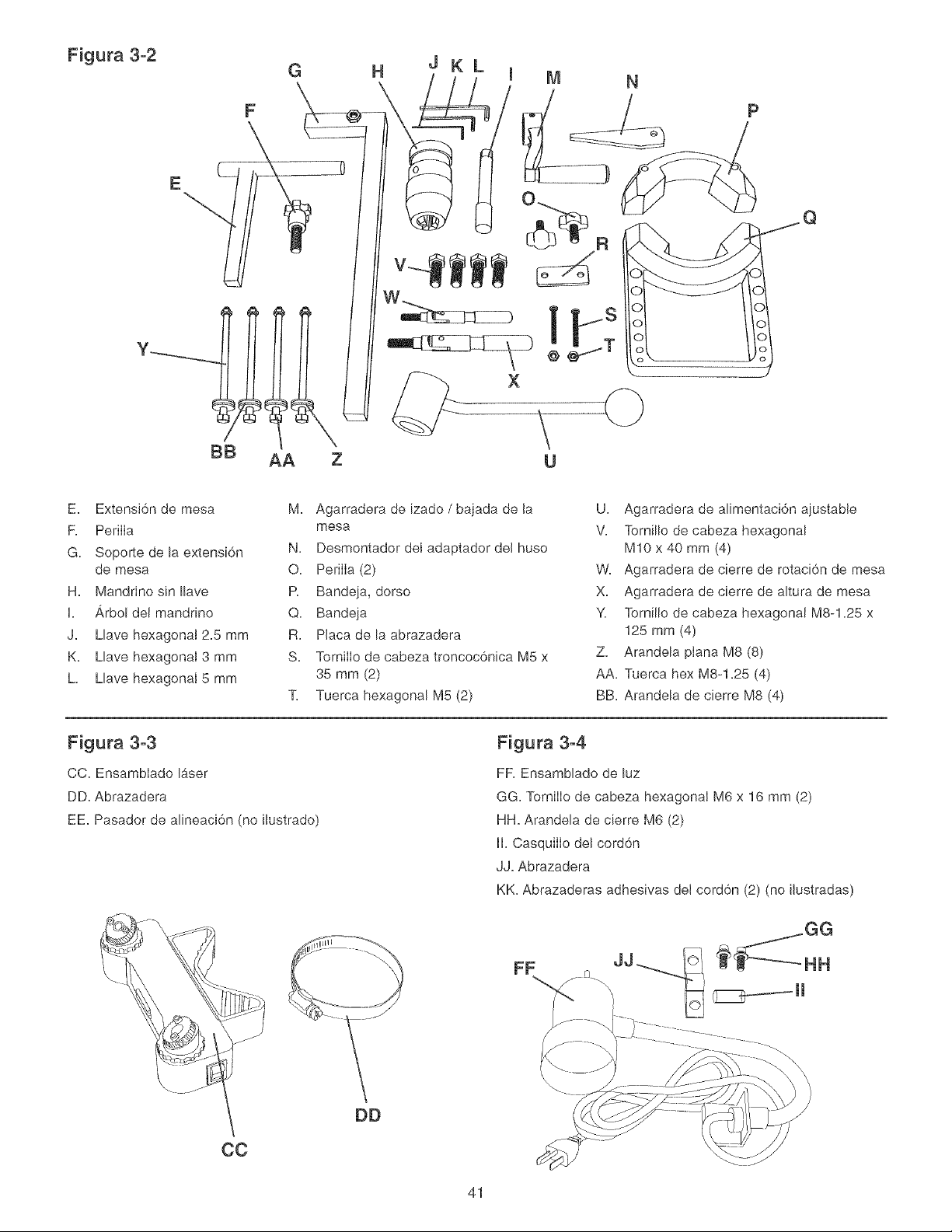
Figura 3-2
E
G
F
BB Z
HJKL
E. Extensi6n de mesa
F. PerilIa
G. Soporte de la extensl6n
de mesa
H. Mandrino sin Ilave
I. Arbol del mandrino
J. Llave hexagonal 2.5 mm
K. Llave hexagonal 3 mm
h Llave hexagonal 5 mm
M. Agarradera de [zado /bajada de la
mesa
N. Desmontador del adaptador del huso
O. PeriIIa (2)
R Bandeja, dorso
Q. Bandeja
R. Placa de la abrazadera
S. TornilIo de cabeza troncoc6n[ca M5 x
35 mm (2)
11 Tuerca hexagonal M5 (2)
U. Agarradera de al[mentaci6n ajustable
V. Tornillo de cabeza hexagonal
M10 x 40 mm (4)
W. Agarradera de c[erre de rotac[6n de mesa
X. Agarradera de c[erre de altura de mesa
Y. Ternillo de cabeza hexagonal M8-1.25 x
125 mm (4)
Z. Arandela plana M8 (8)
AA. Tuerca hex M8-1.25 (4)
BB. Arandela de c[erre M8 (4)
Figura 3-3
CC. EnsambIado laser
DD. Abrazadera
EE. Pasador de al[neaci6n (no ilustrado)
Figura 3-4
FR Ensamblado de luz
GG. TorniIIo de cabeza hexagonaI M6 x 16 mm (2)
HH. Arandela de c[erre M6 (2)
II. CasquiIIo del cord6n
JJ. Abrazadera
KK. Abrazaderas adhesivas del cord6n (2) (no ilustradas)
FF
41
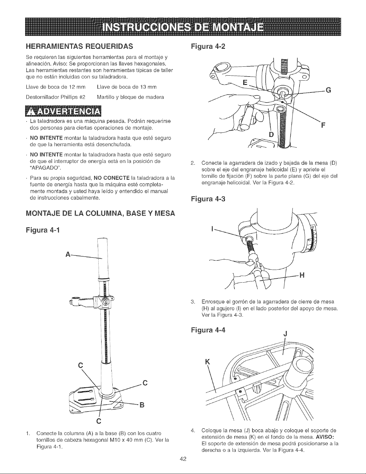
HERRAMUENTAS REQUERUBAS
Se requieren Ias siguientes herramientas para el montaje y
alineaci6n. Aviso: Se proporcionan las Ilaves hexagonales.
Las herramientas restantes son herramientas t[picas de taller
que no estan incluidas con su taladradora.
Llave de boca de 12 mm Llave de boca de 13 mm
Destornillador Phillips #2 Martillo y bloque de madera
La taladradora es una maquina pesada. Podr_n requerirse
dos personas para ciertas operaciones de montaje.
NO INTENTE montar la taladradora hasta que este seguro
de que la herramienta est,. desenchufada.
NO INTENTE montar la taladradora hasta que este seguro
de que el interruptor de energfa esta en la posici6n de
"APAGADO".
Para su propia seguridad, NO CONECTE la taladradora a la
fuente de energ[a hasta que Ia maquina este completa-
mente montada y usted haya le[do y entendido el manual
de instrucciones cabalmente.
MONTAJE DE LA COLUMNA, BASE Y MESA
Figura 4-1
i [
Figura 4-2
o
G
2= Conecte la agarradera de izado y bajada de la mesa (D)
sobre el eje del engranaje heIicoidal (E) y apriete eI
tornillo de fijaci6n (F) sobre la parte plana (G) del eje del
engranaje helicoidal Vet la Figura 4-2=
Figura 4-3
[
I
I
C
c
C
Conecte la columna (A) a Ia base (B) con los cuatro
tornilIos de cabeza hexagonal M10 x 40 mm (C). Ver la
Figura 4-1.
3. Enrosque el gorr6n de Ia agarradera de cierre de mesa
(H) al aguiero (I) en el lado posterior del apoyo de mesa.
Vet la Figura 4-3.
Figura 4-4 J
K
42
4= Coloque la mesa (J) boca abajo y coloque el soporte de
extensi6n de mesa (K) en eI fondo de la mesa. AVJSO:
El soporte de extensi6n de mesa podra posicionarse a la
derecha o a la izquierda= Ver la Figura 4-4=
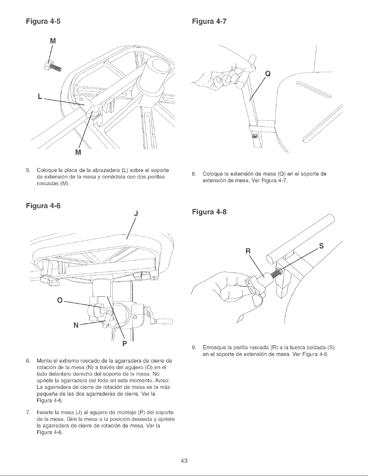
Figura 4-5 Figura 4-7
Q
/C_
M
5. Coloque la placa de la abrazadera (L) sobre eI soporte
de extensi6n de la mesa y conectela con dos perillas
roscadas (M).
8. Coloque la extensi6n de mesa (Q) en el soporte de
extensi6n de mesa. Ver Figura 4-7.
Figura 4-6
J
/
Figura 4-8
.1.
R y
N
6,
7,
Monte el extremo roscado de ia agarradera de cierre de
rotaci6n de la mesa (N) a traves del agujero (O) en el
lado delantero derecho del soporte de la mesa. No
apriete la agarradera del todo en este momento. Aviso:
La agarradera de cierre de rotaci6n de mesa es iamb, s
pequefia de ias dos agarraderas de cierre. Ver la
Figura 4-6.
hserte la mesa (J) al agujero de montaje (P) dei soporte
de la mesa. Gire la mesa a la posici6n deseada y apriete
la agarradera de cierre de rotaci6n de mesa. Ver la
Figura 4-6.
9. Enrosque Ia perilIa roscada (R) a la tuerca soldada (S)
en el soporte de extensi6n de mesa. Ver Figura 4-8.
43
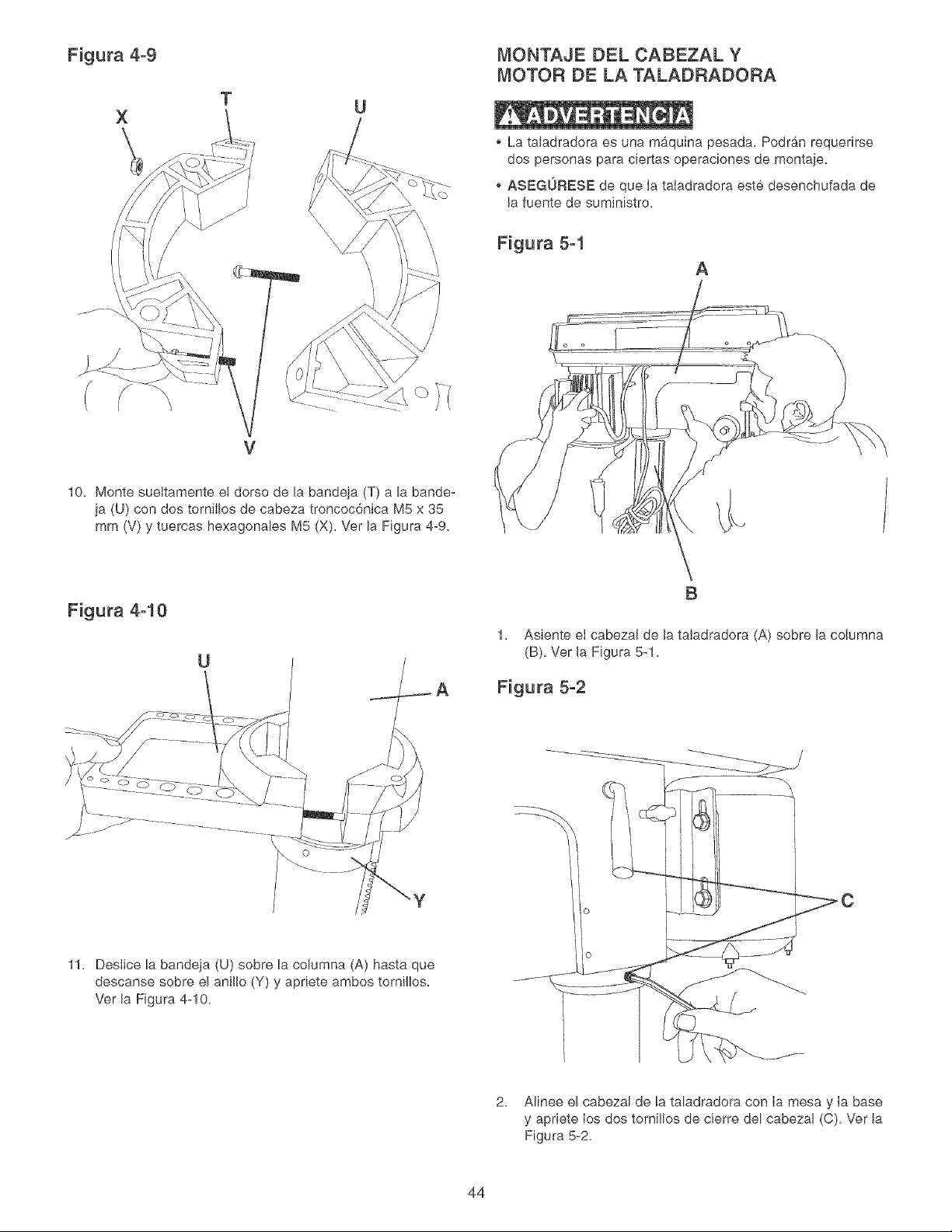
Figura 4-9 MONTAJE DEL CABEZAL Y
MOTOR DE LA TALADRADORA
X
\
T
La taladradora es una maquina pesada. Podran requedrse
dos personas para ciertas operaciones de montaje,
o ASEGORESE de que Ia taladradora este desenchufada de
la fuente de suministro,
Figura 5-1
A
V
10, Monte sueltamente e! dorso de la bandeja (T) a la bande-
ja (U) con dos tornilIos de cabeza troncoc6nica M5 x 35
mm (V) y tuercas hexagonales M5 (X), Ver la Figura 4-9,
Figura 4-10
U
B
1. Asiente eI cabezal de la taladradora (A) sobre la columna
(B)= Vet la Figura 5-1=
Figura 5-2
11= Desiice la bandeja (U) sobre la columna (A) hasta que
descanse sobre e! anillo (Y) y apriete ambos tornillos,
Vet la Figura 4-10=
2, Mnee el cabezar de la taladradora con Ia mesa y Ia base
y apriete Ios dos tornillos de cierre del cabezal (C)= Vet la
Figura 5-2=
44
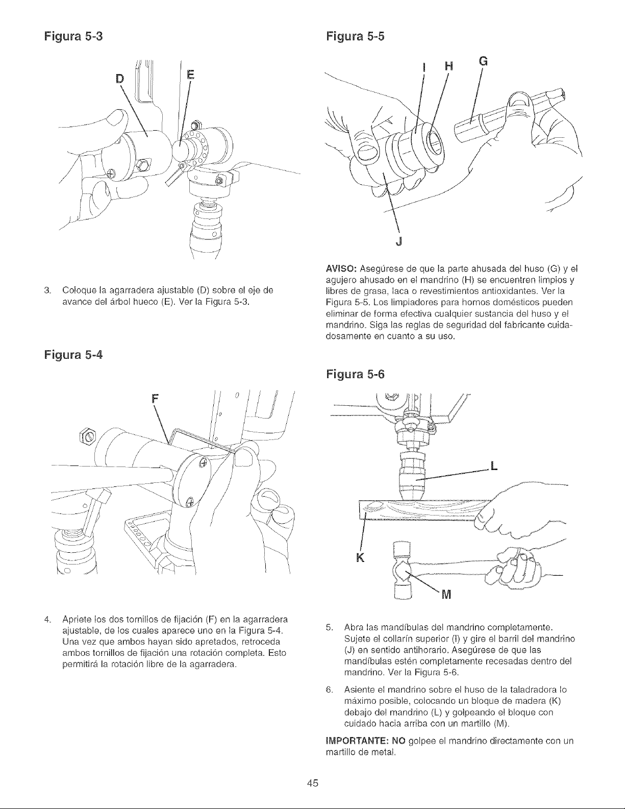
Figura 5-3 Figura 5-5
EI H G
3, Coloque la agarradera ajustable (D) sobre el eje de
avarice del b,rbol hueco (E), Ver la Figura 5-3,
Figura 5-4
F
AVJSO: Aseg0rese de que la parte ahusada del huso (G) y eI
agujero ahusado en eI mandfino (H) se encuentren Iimpios y
fibres de grasa, Iaca o revestimientos antioxidantes, Ver la
Figura 5-5, Los limpiadores para homes domesticos pueden
eliminar de forma efectiva cualquier sustancia del huso y ei
mandrino, Siga las reglas de seguridad del fabricante cuida-
dosamente en cuanto a su use,
Figura 5-6
K
4. Apriete los dos tornilIos de fijaci6n (F) en la agarradera
ajustabIe, de Ios cuales aparece uno en Ia Figura 5-4,
Una vez que ambos hayan side apretados, retroceda
ambos tornillos de fijaci6n una rotaci6n completa, Esto
permitira la rotaci6n fibre de la agarradera,
5, Abra Ias mand(bulas del mandrino completamente,
Sujete ei collar[n superior (I) y gire el barril deI mandrino
(J) en sentido antihorario, Asegurese de que las
mandfbulas esten completamente recesadas dentro del
mandrino, Ver la Figura 5-6,
6, Asiente eI mandrino sobre ei huso de la taladradora Io
maximo posible, colocando un bloque de madera (K)
debajo dei mandrino (L) y goipeando et bloque con
cuidado hacia arriba con un martillo (M),
tMPOF{TANTE: NO golpee el mandrino directamente con un
martillo de metal,
45
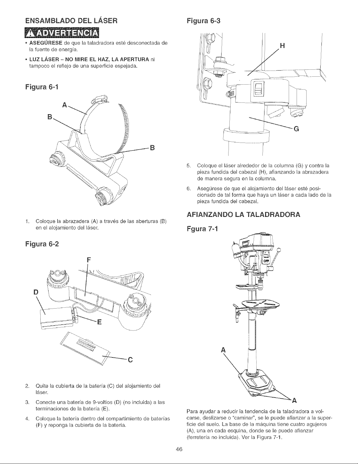
ENSAMBLADO DEL LASER Figura 6-3
o ASEGURESE de que la taiadradora este desconectada de
la fuente de energ[a.
o LUZ LASER - NO MIRE EL HAZ, LA APERTURA ni
tampoco el refiejo de una superficie espejada.
Figura 6-1
1. Coloque la abrazadera (A) a traves de las aberturas (B)
en el alojamiento del Ib,ser.
Figura 6-2
F
D
5. Coloque el laser alrededor de la columna (G) y contra la
pieza fundida del cabezal (H), afianzando la abrazadera
de manera segura en la columna.
6. Aseg0rese de que e! alojamiento del Ib,ser este posi-
cionado de tal forma que haya un Ib,ser a cada lade de la
pieza fundida del cabezal.
AFIANZANDO LA TALADRADORA
Fgura 7-1
2.
3.
4.
C
Quite la cubierta de la baterfa (C) del alojamiento del
Ib,ser.
Conecte una bater[a de 9-voltios (D) (no incluida) alas
terminaciones de la bater[a (E).
CoIoque Ia bater[a dentro deI compartimiento de bateffas
(F) y reponga la cubierta de la bater[a.
A
Para ayudar a reducir Ia tendencia de la taladradora a vol-
carse, deslizarse o "caminar", se le puede afianzar a la super-
ficie deI suelo. La base de la maquina tiene cuatro agujeros
(A), una en cada esquina, donde se Ie puede afianzar
(ferreter[a no incluida). Ver la Figura 7-1.
46
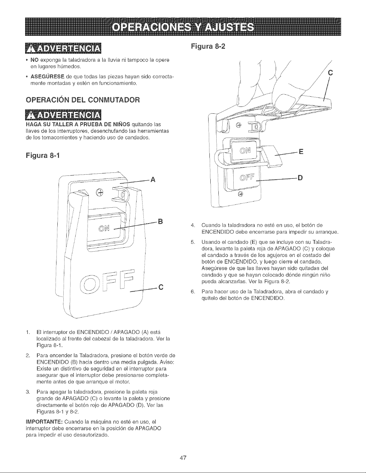
o NO exponga la taladradora a Ja Jluvia ni tampoco Ja opere
en Jugares hOmedos.
ASEGURESE de que todas las piezas hayan sido correcta-
mente montadas y esten en funcionamiento.
OPERACION DEL CONMUTADOR
HAGA SU TALLER A PRUEBA DE NINOS quitando las
Jlaves de los interruptores, desenchufando Ias herramientas
de los tomacorrientes y haciendo uso de candados.
Figura 8-2
Figura 8-1
....... j---"J ....
4. Cuando la taladradora no este en uso, el bot6n de
ENCENDDO debe encerrarse para impedir su arranque.
5. Usando el candado (E) que se [nc[uye con su Taladra-
dora, levante la paleta roja de APAGADO (C) y coloque
eI candado a traves de Ios agujeros en el costado del
bot6n de ENCENDIDO, y luego cierre el candado.
Aseg0rese de que las IIaves hayan sido quitadas del
candado y que se hayan colocado d6nde ningOn ni5o
pueda alcanzarlas. Ver Ja Figura 8-2.
6. Para hacer uso de Ia Taladradora, abra el candado y
qu[telo de[ bot6n de ENCENDIDO.
1. El [nterruptor de ENCENDIDO/APAGADO (A) esta
Iocalizado aI frente del cabezaI de Jataladradora. Ver la
Figura 8-1.
2. Para encender la Ta[adradora, presione ei bot6n verde de
ENCENDIDO (B) hacia dentro una media pulgada. Aviso:
Existe un distintivo de seguridad en et [nterruptor para
asegurar que el [nterruptor debe presionarse compJeta-
mente antes de que arranque el motor.
3. Para apagar la taladradora, presione la pa[eta roja
grande de APAGADO (C) o levante la paleta y presione
directamente el bot6n rojo de APAGADO (D). Ver las
Figuras 8-1 y 8-2.
[MPORTANTE: Cuando Ia maquina no este en uso, el
interruptor debe encerrarse en Ia posici6n de APAGADO
para impedir el uso desautorizado.
47
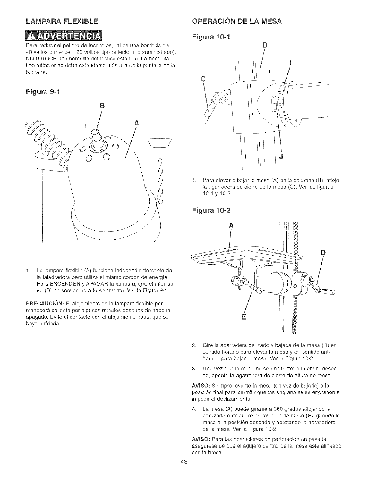
LAMPARA FLEXIBLE
Para reducir el peIigro de incendios, utilice una bombilla de
40 vatios o menos, 120 voltios tipo reflector (no suministrado).
NO UTILICE una bombilIa domestica estandar. La bombilla
tipo reflector no debe extenderse mas alia de la pantalla de la
lampara,
Figura 9-1
B
A
©©
La ffimpara flexible (A) funciona independientemente de
la taladradora pero utiliza el mismo cord6n de energ[a.
Para ENCENDER y APAGAR la lampara, gire el interrup-
ter (B) en sentido horatio solamente. Ver la Figura 9-1.
PRECAUCl6N: El alojamiento de la lampara flexible per-
manecer_ caliente per algunos minutes despues de haberla
apagado. Evite el contacto con el alojamiento hasta que se
haya enfriado.
OPERACION DE LA MESA
Figura 10-1
B
C
1. Para elevar o bajar Ia mesa (A) en Ia columna (B), afloje
la agarradera de cierre de la mesa (C). Ver las figuras
10-1 y 10-2.
Figura 10-2
A
D
E
48
2. Gire la agarradera de izado y bajada de [a mesa (D) en
sentido horario para eievar la mesa yen sentido anti-
horario para bajar la mesa. Ver la Figura 10-2.
3. Una vez que la maquina se encuentre a la altura desea-
da, apriete la agarradera de cierre de altura de mesa.
AWSO: Siempre ievante ia mesa (en vez de bajarla) a ia
posici6n final para permitir que los engranajes se engranen e
impedir el deslizamiento.
4. La mesa (A) puede girarse a 360 grades aflojando ia
abrazadera de cierre de rotaci6n de mesa (E), girando la
mesa a la posici6n deseada y apretando la abrazadera
de la mesa. Ver [a Figura 10-2.
AVISO: Para las operaciones de perforaci6n en pasada,
aseg0rese de que el agujero central de la mesa este aiineado
con la broca.
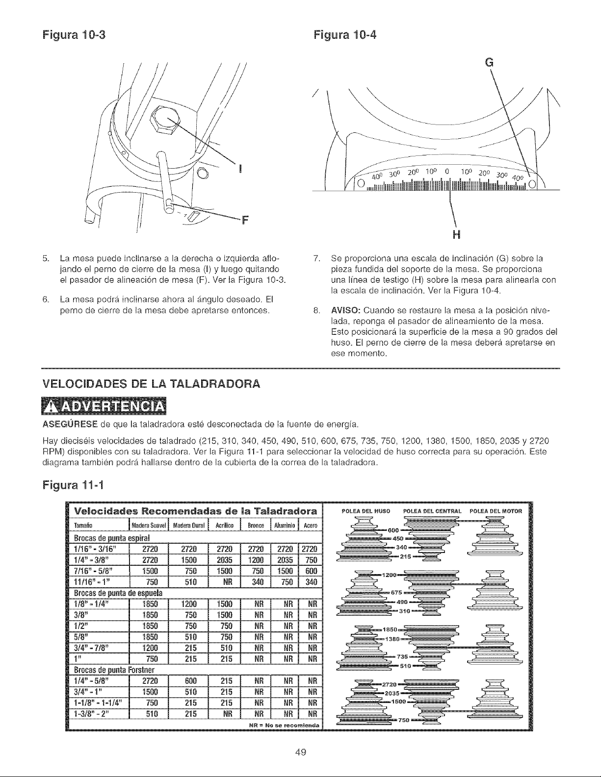
Figura 10-3 Figura 10-4
G
20 o 100 0 10° 200 300
5.
6.
La mesa puede inclinarse a la derecha o izqu+erda afio-
jando el perno de cierre de Ia mesa (H)y Iuego quitando
el pasador de alineaci6n de mesa (F). Ver Ia Figura 10+3+
La mesa podra inclinarse ahora al _ngulo deseado. El
perno de cierre de la mesa debe apretarse entonces.
H
7.
8.
Se proporciona una escala de inclinaci6n (G) sobre Ea
pieza fundida del soporte de la mesa. Se proporciona
una I[nea de testigo (H) sobre Ja mesa para alinearta con
la escala de inclinaci6n. Ver la Figura 10+4+
AWSO: Cuando se restaure la mesa a Ia posici6n nive-
lada, reponga el pasador de alineamiento de Ia mesa.
Esto posicionar_ Ia superficie de la mesa a 90 grades del
huso. El perno de cierre de la mesa debera apretarse en
ese memento+
VELOCIDADES DE LA TALADRADORA
ASEGURESE de que la taladradora este desconectada de Ia fuente de energia.
Hay diec+seis velocidades de ta+adrado (215, 310, 340, 450, 490, 510, 600, 675, 735, 750, 1200, 1380, 1500, 1850, 2035 y 2720
RPM) disponiUes con su taladradora. Ver la Figura 11-1 para seleccionar Ia velocidad de huso correcta para su operaci6n. Este
diagrama tambien podrb, hallarse dentro de la cubierta de la correa de la taladradora.
Figura 11-1
Veiocidades Re¢emendadas de Ja Taladradera
+0+0 1 o°0,0+o0+0,1+°0,000,0,1A°+00I 0o°o0IA'om'o'01"00+
8tocasde puntaespirai
1118"° 3/18" 2728 2720 2720 2720 2720 12728
1/4" - 3/8" 2728 1508 2835 1208 2835 758
7/15" =5/8" 1588 758 1580 758 1508 600
11/10" =1" 758 518 NR 348 750 340
Brecasde puatade espuela
1/8" =1/4" 1858 1208 1580 NR NR NR
3/8" 1858 758 1580 NR NR NR
1/2" 1858 758 750 NR NR NR
518" 1858 518 750 NR NR NR
3/4" =7/8" 1200 215 510 NR NR NR
1" 758 215 215 NR NR NR
8mcasde paataForstner
1/4" -5/8" 2728 @8 215 NR NR NR
3/4"o1" 1588 518 215 NR NR NR
1ol/8" =1ol/4" 758 218 215 NR NR NR
1=3/8"=2" 518 215 NR NR NR NR
NR =No _e recomienda
POLEA _EL HU$O POLEA _EL CENT_L POLEA _EL MOTOR
49
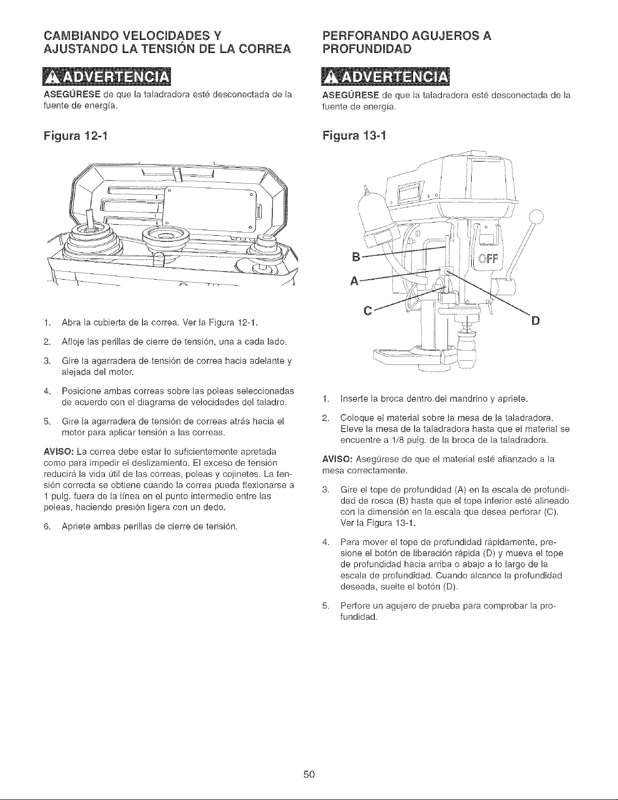
CAMBIANDO VELOCIDADES Y PERFORANDO AGUJEROS A
AJUSTANDO LA TENSI6N DE LA CORREA PROFUNDIDAD
ASEGURESE de que la taladradora este desconectada de Ja
fuente de energfa,
ASEGURESE de que Jataladradora este desconectada de la
fuente de energ[a,
Figura 12-1 Figura 13-1
A
1, Abra Jacubierta de Ia correa, Ver Ia Figura 12-1,
2, Afioje Jas perillas de cierre de tensi6n, una a cada lado,
3, Gire Ia agarradera de tensi6n de correa hacia adelante y
alejada del motor,
4, Posicione ambas correas sobre Jas poleas seleccionadas
de acuerdo con el diagrama de veIocidades del taladro,
5, Gire Ia agarradera de tensi6n de correas atras hacia el
motor para aplicar tensi6n alas correas,
AVJSO: La correa debe estar Io suficientemente apretada
como para impedir el deslizamiento, El exceso de tensi6n
reducira ia vida 0tii de las correas, poleas y cojinetes, La ten-
si6n correcta se obtiene cuando ia correa pueda fiexionarse a
1 pulg, fuera de ia i[nea en el punto intermedio entre las
poleas, haciendo presi6n ligera con un dedo,
6, Apriete ambas perillas de cierre de tensi6n,
CD
1, Inserte la broca dentro dei mandrino y apriete,
2, Coloque el materia! sobre ia mesa de la taladradora,
Eleve la mesa de la taladradora hasta que el material se
encuentre a 1/8 puig, de la broca de la taladradora,
AVISO: Aseg0rese de que el material este afianzado a Ja
mesa oorrectamente,
3,
4,
5,
Gire el tope de profundidad (A) en Ia escala de profundi-
dad de rosca (B) hasta que et tope inferior este aJineado
con la dimensi6n en la escala que desea perforar (C),
Ver Ia Figura 13-1,
Para mover et tope de profundidad rb,pidamente, pre-
sione el bot6n de Iiberaci6n r&pida (D) y mueva el tope
de profundidad hacia arriba o abajo a Io largo de la
escala de profundJdad, Cuando alcance la profundidad
deseada, suelte eJ bot6n (D),
Perfore un agujero de prueba para comprobar Ja pro-
fundidad,
5O
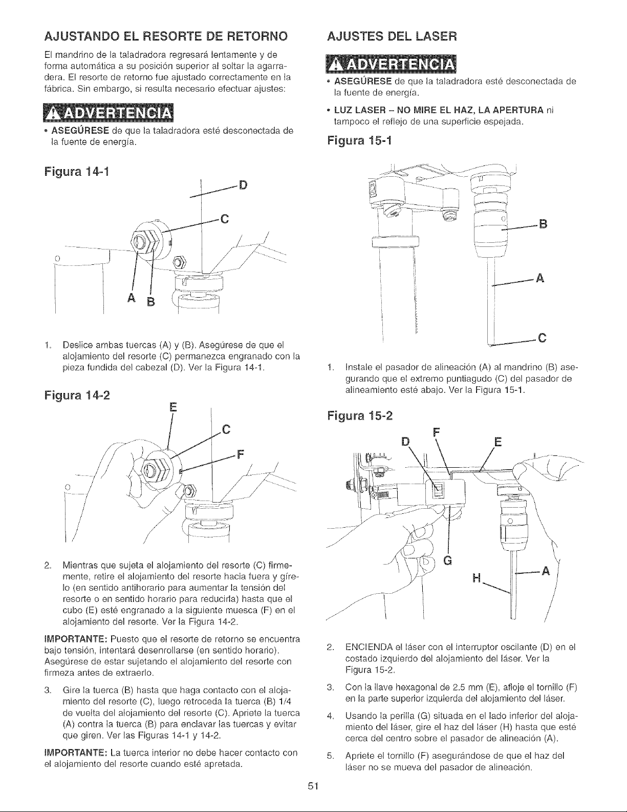
AJUSTANDO EL RESORTE DE RETORNO
El mandrino de la taladradora regresara Ientamente y de
forma automatica a su posici6n superior aI soltar la agarra-
dera. El resorte de retorno fue ajustado correctamente en Ia
fabrica= Sin embargo, si resuIta necesario efectuar ajustes:
ASEGURESE de que la taiadradora este desconectada de
la fuente de energ[a=
AJUSTES DEL LASER
ASEGURESE de que la taladradora este desconectada de
la fuente de energfa=
LUZ LASER = NO MIRE EL HAZ, LA APERTURA ni
tampoco el reflejo de una superficie espejada=
Figura 15-1
Figura 14-1
A
1. Deslice ambas tuercas (A) y (B). Asegurese de que el
alojamiento del resorte (C) permanezca engranado con la
pieza fundida del cabezal (D). Ver la Figura 14-1.
Figura 14-2
=
=
=
..... J
i
ii
1= hstale el pasador de alineaci6n (A) al mandrino (B) ase-
gurando que eI extreme puntiagudo (C) del pasador de
alineamiento este abajo= Ver la Figura 15-1=
Figura 15-2
E
2= Mientras que sujeta el alojamiento del resorte (C) firme-
mente, retire el alojamiento deI resorte hacia fuera y gire-
Io (en sentido antihorario para aumentar Ia tensi6n deI
resorte o en sentido horario para reducirIa) hasta que el
cube (E) este engranado a la siguiente muesca (F) en el
alojamiento del resorte= Ver Ia Figura 14-2=
tMPORTANTE: Puesto que eI resorte de retorno se encuentra
bajo tensi6n, intentara desenrollarse (en sentido horario)=
Aseg0rese de estar sujetando el alojamiento del resorte con
firmeza antes de extraerlo=
3= Gire Ia tuerca (B) hasta que haga contacto con el aloja-
miento del resorte (C), luego retroceda Ia tuerca (B) 1/4
de vueIta del aIojamiento deI resorte (C)=Apriete la tuerca
(A) contra Ia tuerca (B) para enclavar Ias tuercas y evitar
que giren= Ver las Figuras 14-1 y 14-2=
tMPORTANTE: La tuerca interior no debe hacer contacto con
el alojamiento del resorte cuando este apretada=
2.
3.
4.
5.
51
H
ENCENDA el Ib_sercon el interruptor oscilante (D) en el
costado izquierdo del alojamiento del Ib,ser= Ver la
Figura 15-2=
Con Ia Ilave hexagonal de 2=5 mm (E), afloje el tornillo (F)
en la parte superior izquierda del alojamiento del laser=
Usando Ia periIIa (G) situada en el Iado inferior del aIoja-
miento de! Ib,ser, gire e! haz del Ib_ser(H) hasta que este
cerca del centre sobre el pasador de alineaci6n (A)=
Apriete el torniIIo (F) asegurandose de que eI haz del
laser no se mueva del pasador de alineaci6n=
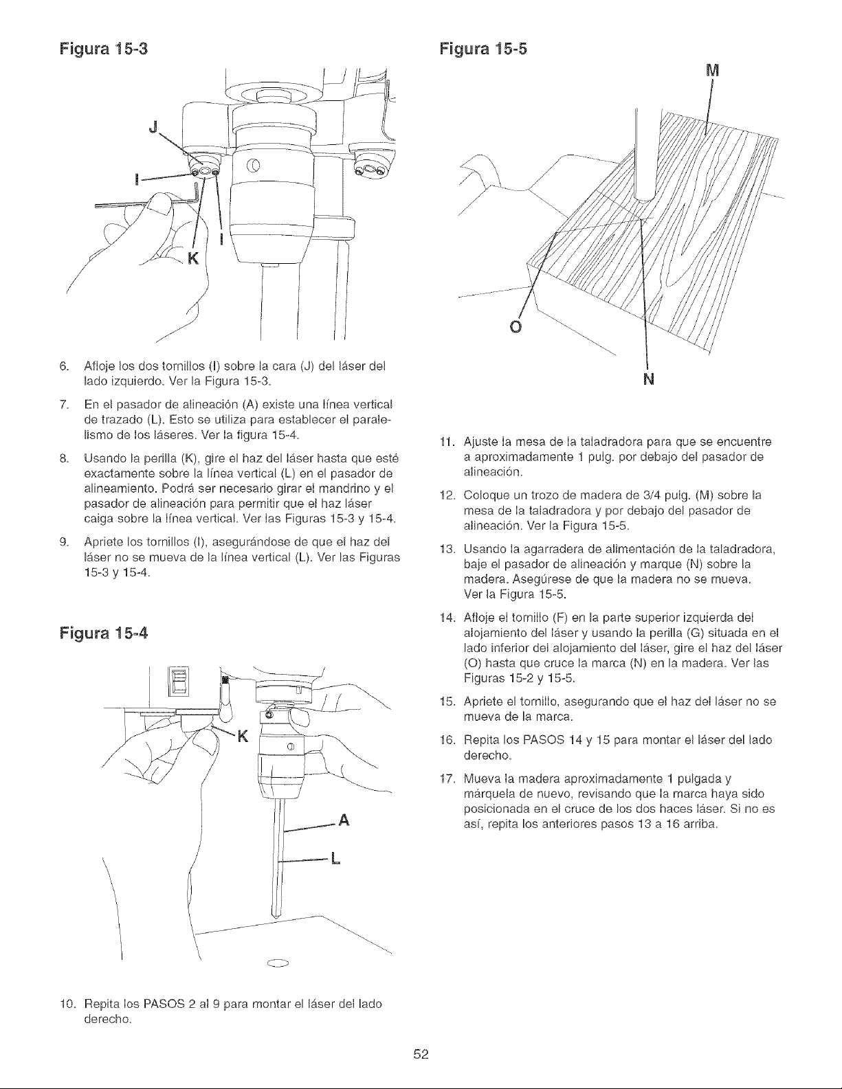
Figura 15-3 Figura 15-5
M
J
J
6. Afloje los dos tornillos d) sobre la cara (J) del laser del
lade izquierdo. Ver la Figura 15-3.
7. En e! pasador de alineaci6n (A) existe una I[nea vertical
de trazado (L). Esto se utiliza para establecer el parale-
lismo de los laseres. Ver Ia figura 15-4.
8. Usando la perilla (K), gire el haz del laser hasta que este
exactamente sobre la I[nea vertical (L) en el pasador de
alineamiento. Podra ser necesario girar el mandrino y el
pasador de alineaci6n para permitir que et haz laser
caiga sobre la I[nea vertical. Ver Ias Figuras 15-3 y 15-4.
9. Apriete los torni!!os (I), asegurandose de que el haz del
laser no se mueva de la I[nea vertical (L). Ver las Figuras
15-3 y 15-4.
K
11. Ajuste Ia mesa de Ia taladradora para que se encuentre
a aproximadamente 1 pulg. per debaio del pasador de
alineaci6n.
12. Coloque un trozo de madera de 3/4 pulg. (M) sobre la
mesa de Ia taladradora y per debajo del pasador de
alineaci6n. Ver la Figura 15-5.
13. Usando Ia agarradera de alimentaci6n de Ia taladradora,
baie el pasador de alineaci6n y marque (N) sobre la
madera. AsegOrese de que la madera no se mueva.
Ver la Figura 15-5.
14. Aftoje el tornilIo (F) en la parte superior izquierda deI
aloiamiento del laser y usando Ia perilla (G) situada en el
lado inferior deI alojamiento del laser, gire el haz del laser
(0) hasta que cruce Ia marca (N) en la madera. Ver las
Figuras 15-2 y 15-5.
Apriete el tornilIo, asegurando que el haz del laser no se
mueva de la marca.
15.
16.
17.
Repita los PASOS 14 y 15 para montar el laser del lado
derecho.
Mueva Ia madera aproximadamente 1 pulgada y
marquela de nuevo, revisando que Ia marca haya sido
posicionada en el cruce de los dos haces laser. Si no es
as[, repita los anteriores pasos 13 a 16 arriba.
\
\
10. Repita los PASOS 2 al 9 para montar el laser del lado
derecho.
52
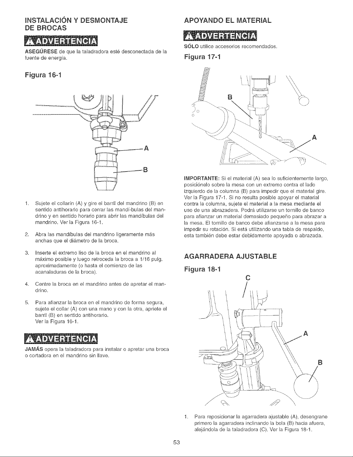
INSTALACI6N Y DESMONTAJE
DE BROCAS
APOYANDO EL MATERIAL
ASEGURESE de que la taladradora este desconectada de la
fuente de energfa.
SOLO utilice accesorios recomendados.
Figura 17-1
Figura 18-1
2,
3,
4,
5,
jB
Sujete el collar[n (A) y gire el barriI del mandrino (B) en
sentido antihorario para cerrar Ias mand[-bulas deI man-
drino yen sentido horario para abrir las mand[butas del
manddno. Ver la Figura 16-1.
Abra Ias mandfbulas del mandrino ligeramente mas
anchas que el diametro de la broca.
Inserte et extremo %0 de la broca en el mandrino al
m&ximo posible y Iuego retroceda la broca a 1/16 pulg.
aproximadamente (o hasta el comienzo de Ias
acanaladuras de Ia broca).
Centre la broca en el mandrino antes de apretar el man-
drino.
Para afianzar la broca en el mandrino de forma segura,
sujete el collar (A) con una mane y con la otra, apriete el
barriI (B) en sentido antihorario.
Ver la Figura 16-1.
JAMAS opera Ia taladradora para instaIar o apretar una broca
o cortadora en el mandrino sin Ilave.
o
B
A
tMPORTANTE: Si el material (A) sea Io suficientemente largo,
posici6nelo sobre la mesa con un extreme contra el lade
izquierdo de Ia columna (B) para impedir que el material gire.
Ver la Figura 17-1. Si no resuIta posibIe apoyar el material
contra la columna, sujete et materiat a la mesa mediante el
use de una abrazadera. Podra utilizarse un tornillo de banco
para afianzar un material demasiado pequeSo para abrazar a
la mesa. El tornillo de banco debe afianzarse a la mesa para
impedir su rotacion. Si est,. utilizando una tabia de respatdo,
esta tambien debe estar debidamente apoyada o abrazada.
AGARRAZ)ERA AJUSTABLE
Figura 18-1
C
A
B
1, Para reposicionar la agarradera ajustable (A), desengrane
primero la agarradera inclinando la boia (B) hacia afuera,
alejandola de la taladradora (C). Ver la Figura 18-1.
53
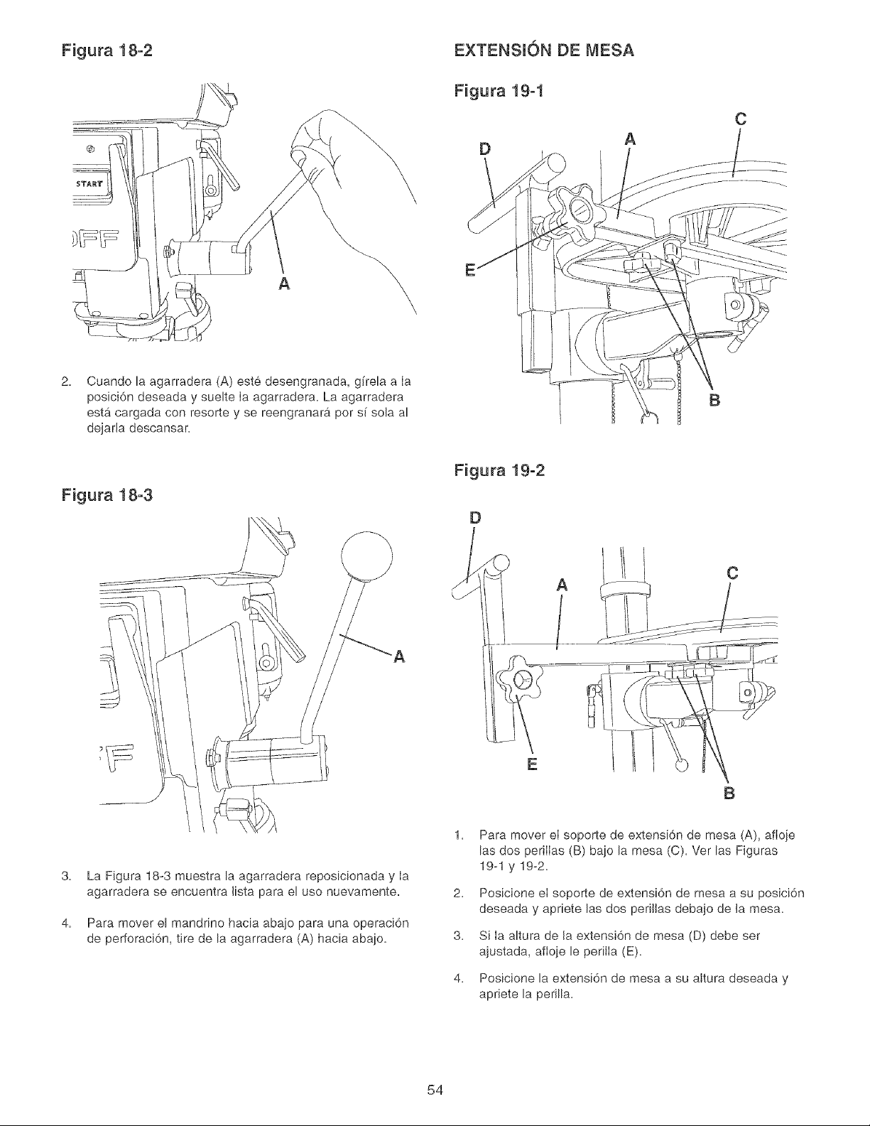
Figura 18-2
2. Cuando la agarradera (A) este desengranada, gffela a Ia
posici6n deseada y suelte Ia agarradera. La agarradera
est9, cargada con resorte y se reengranar_i por s( sola al
dejada descansar.
EXTENSION DE MESA
Figura 19-1
DA
B
C
Figura 18-3
Figura 19-2
D
A
AC
B
3.
4.
La Figura 18-3 muestra la agarradera reposicionada y Ia
agarradera se encuentra lista para el uso nuevamente.
Para mover el mandrino hacia abajo para una operaci6n
de perforaci6n, tire de la agarradera (A) hacia abajo.
1.
2.
3.
4.
Para mover el soporte de extensi6n de mesa (A), afloje
las dos perilIas (B) bajo la mesa (C). Ver las Figuras
19-1 y 19-2.
Posicione el soporte de extensi6n de mesa a su posici6n
deseada y apnete las dos perJlJasdebajo de Ja mesa.
Si Ia altura de la extensi6n de mesa (D) debe ser
ajustada, aftoje le perilla (E).
Posicione la extensi6n de mesa a su aJtura deseada y
aprJete la perilla.
54
VELOCIDADES DE PERFORACION
APROPIADAS
Los factores que determinan Ia mqor velocidad a ser utiIizada
en cualquier funci6n de taladrado son: eI tipo de material a
ser elaborado, el tamaflo del agujero, tipo de broca u otra
cortadora, y la calidad del corte deseado.
Utilice la velocidad recomendada para la broca y el material.
PERFORACI6N DE MADERAS
Las brocas espiraIes, aunque esten disefladas para la per-
foraci6n de metales, pueden ser utilizadas tambien para el
taIadrado de agujeros en la madera. No obstante, se prefiere
per Io general el use de brocas de espueIa o brocas Forstner
para Ia perforaci6n de madera, ya que cortan un agujero de
fondo cuadrado y estan disefiadas para la extracci6n de
astillas de madera. No utiIice las brocas de mane con punta
de tornilIo, ya que a las velocidades de Ia taIadradora, levan-
taran y harb,n girar la madera.
Para la perforaci6n en pasada, debe alinear la mesa para que
la broca entre en el aguiero central. Trace una I[nea vertical
en ia parte delantera de Ia columna y una marca de referen-
cia sobre el soporte de Ia mesa y el cabezal de la taladra-
dora, de mode que la mesa y el cabezat de Ia taladradora
puedan ser abrazadas en la posici6n central a cualquier
altura.
Alimente Ia broca lentamente cuando la broca este a punto
de cortar a traves de la madera para impedir el astillamiento
de Ia cara inferior. Utilice un trozo de madera descartada
come respaldo debajo del material. Esto ayuda a reducir el
astillamiento y protege la punta de la broca.
PERFORACI6N DE METALES,
ALUMINIO O BRONCE
NUNCA sujete el materiaI con las manos descubiertas.
SIEMPRE utiIice abrazaderas o tornillos de banco para
sujetar su material.
S61o debe hacerse use de brocas espirales en Ia perforaci6n
de materiales. Nunca sujete el material con Ias manes des-
cubiertas; utiIice abrazaderas o torniiIos de banco en todo
memento. La broca puede atrapar el material en cualquier
momento, particularmente cuando se rompe a trav6,s del
material. Si eI material se escapa de la mane del operano,
este uItimo puede resultar hefido. En todo caso, Ia taladra-
dora quedarb, averiada si eI material se golpea contra la
columns.
El materia! debe set abrazado o sqetado con firmeza en un
tornil!o de banco durante Ia perforaci6n. Cualquier inclina-
miento, torcedura o movimiento lateral tiene como resultado
no s61o un agqero rudimentano, sine que aumenta el riesgo
de ruptura de Ia broca. Para matefiales pianos, coloque el
material sobre una base de madera y abraceb firmemente
contra Ia mesa para impedir que gire. Si el material es de
forma irregular y no puede colocarse de manera plana sobre
la mesa, debe ser bloqueado y abrazada de manera segura.
Durante Ia perforaci6n de metabs sera necesano lubncar la
punta de la broca con aceite para impedir su sobrecabnta-
miento.
OPERACI6N DE PERFORACI6N
Utilice un punz6n de centrar para impactar el material en
d6nde desea el agqero. Esto impedirb, que Ia broca camine
al iniciar Ia operaci6n de perforaci6n. Antes de encender la
taladradora, encienda el laser y alinee Ias crucetas con Ia
marca central en el material. Aseg0rese de que el material
este debidamente apoyado o afianzado a la mesa. Para la
perforaci6n en pasada, aseg0rese de que el agqero central
de la mesa este alineado con la broca. Encienda la taladra-
dora y comience a alimentar el mandrino de la taladradora
hacia abajo con las agarraderas de alimentaci6n.
LA ALIMENTACK)N EXCESlVAMENTE RAPIDA podra
hacer que la correa o la broca se deslicen o se rompan, que
el motor se atasque, o que el material se afioje de Ia mesa.
Jamas trate de apresurar el trabajo. Permita que la tatadra-
dora funcione de manera uniforme.
CAMBIO DEL VOLTAJE DEL MOTOR
ASEGORESE de desconectar Ia m_.quina de la fuente de
alimentaci6n antes de trabajar en el motor.
Pfdale a un electricista certificado que haga todas las co-
nexiones electricas. Se deben mantener todos los c6digos
Iocabs y estatabs. El motor que se suministra con la
Taladradora es un motor monofb, sico de doble voltaie para
120/240 V. El motor esta alambrado de fabnca para funcionar
con 120 V. Para cambiar su funcionamiento a 240 V, siga Ias
instrucciones que se dan abajo. Para hacer esto tambi6,n es
necesado cambiar el enchufe de 120 V que se suministra con
la m_.quina per un enchufe certificado por UL/CSA (que no se
incluye) adecuado para 240 V y que acepte la cornente nomi-
nal indicada para et motor. El motor con el enchufe de 240 V
debe conectarse solamente a un tomacorrientes que tenga Ia
misma configuraci6n deI enchufe. Para el tomacordentes de
240 V no se ofrece ni debe usarse ning0n adaptador.
1. Aseg0rese de que el interrupter este APAGADO y des-
conecte et cord6n electrico de Ia fuente de alimentaci6n.
2. Venfique en el r6tulo del motor que el voltaje del motor
sea dobb.
3. Si el r6tulo del motor dice que el voltaje es dobb, quite la
tapa de la caja de empalmes deI motor.
4. Utilizando el diagrama electrico que esta dentro de Ia
tapa de la caja de empalmes, reconecte los cables del
motor para funcionar con 240 V.
5. Vuelva a ponede la tapa a la caja de empalmes.
6. Reemplace el enchufe de 120 V por un enchufe de 240 V
certificado per UL/CSA y clasificado para la cornente del
motor.
7. El interruptor de ENCENDIDO /APAGADO es un
interrupter de cuatro (4) polos y no necesita ninguna
modificaci6n.
55
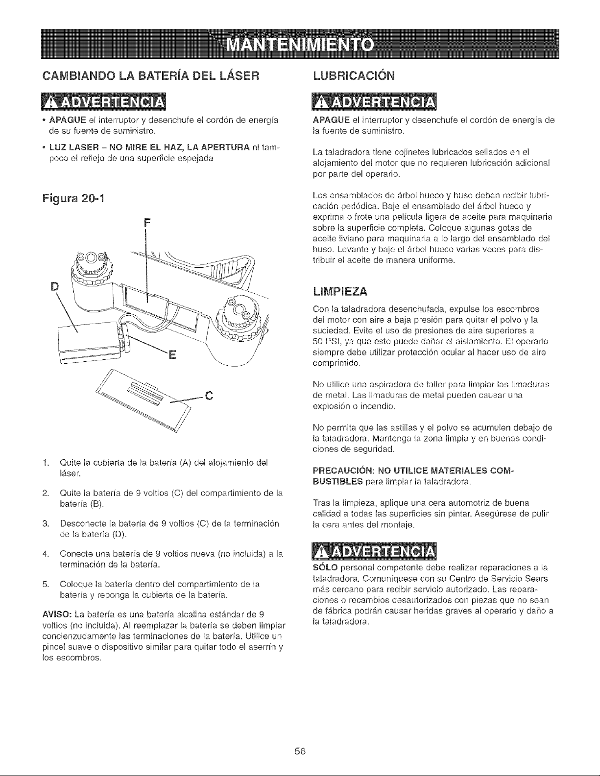
CAMB[ANDO LA BATERiA DEL LASER LUBRICAC[ON
APAGUE el interrupter y desenchufe el cord6n de energfa
de su fuente de suministro.
o LUZ LASER - NO M_RE EL HAZ, LA APERTURA ni tam-
poco el reflejo de una superficie espejada
Figura 20-1
F
D
1. Quite la cubierta de la baterfa (A) del aIojamiento del
laser.
2. Quite la bateffa de 9 voltios (C) del compartimiento de la
baterfa (B).
3. Desconecte Ia bateffa de 9 voltios (C) de la terminaci6n
de la bateffa (D).
4. Conecte una bateffa de 9 voltios nueva (no induida a la
term[naci6n de la bateffa.
5. Coloque Ia baterfa dentro deI compartimiento de la
bateffa y reponga la cubierta de la bateffa.
AVJSO: La bateffa es una baterfa alcalina estandar de 9
voltios (no induida). AI reemplazar la bateffa se deben limpiar
concienzudamente las terminaciones de la baterfa. Utilice un
pincel suave o dispositivo similar para quitar todo el aserrfn y
los escombros.
APAGUE el interrupter y desenchufe el cord6n de energfa de
la fuente de sumin[stro.
La taladradora tiene cojinetes lubricados se[Iados en eI
a!ojamiento deI motor que no requieren lubricaci6n adicional
per parte del operario.
Los ensamblados de arbol hueco y huso deben recibir Iubri-
caci6n peri6dica. Baje el ensamblado de[ arbol hueco y
exprima o frote una peffcula Iigera de aceite para maquinaria
sobre Ia superficie completa. Coioque algunas gotas de
aceite liviano para maquinaria a Io largo deI ensamblado del
huso. Levante y baje eI arboI hueco varias veces para dis-
tribuir el aceite de manera uniforme.
UMP[EZA
Con Ia taladradora desenchufada, expulse los escombros
del motor con aire a baja presi6n para quitar el polvo y Ia
suciedad. Evite eI use de presiones de aire superiores a
50 PSI, ya que esto puede dafiar et aislamiento. EI operario
s[empre debe utilizar protecci6n ocular al hacer use de aire
comprimido.
No utilice una aspiradora de taller para limpiar las limaduras
de metal. Las Iimaduras de metal pueden causar una
explosi6n o incendio.
No permita que Ias astiilas y el polvo se acumulen debajo de
la taladradora. Mantenga la zona limpia yen buenas condi-
ciones de seguridad.
PRECAUCION: NO UTIUCE MATERIALES COM-
BUSTIBLES para limpiar la taladradora,
Tras Ia limpieza, aplique una cera automotriz de buena
calidad a todas las superficies sin pintar. Aseg0rese de pulir
la cera antes del montaie.
SOLO personai competente debe realizar reparaciones a la
taladradora. Comunfquese con su Centro de Servicio Sears
mas cercano para recibir servicio autorizado. Las repara-
ciones o recambios desautorizados con piezas que no sean
de fabrica podran causar heridas graves al operario y dare a
la taladradora.
56
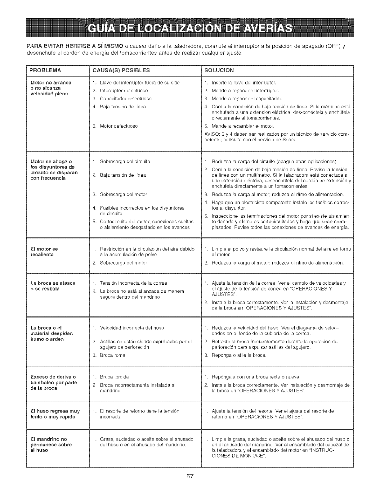
PARA EVSTAR HERIRSE A Si rWlSMO o causar daf_o a la taladradora, conmute el interruptor a la posici6n de apagado (OFF) y
desenchufe el cord6n de energ[a del tomacorrientes antes de realizar cuaIquier ajuste=
PROBLEMA CAUSA(S} POSIBLES SOLUCJ6N
Motor 130 arranca
OnO aIcal3za
velocidad plena
_,_otor se ahoga o
los dieyuntores de
eireuito se disparan
con frecueneia
ERmotor se
recalienta
La broea se atasca
o ee resbala
La broea o el
material despiden
humo o arden
E×ceso de deriva o
bamboReo pot parte
de la broca
El huso regresa muy
lento o muy r&pido
El rnaadrino no
permanece eobre
eBhuso
1. Llave de! interruptor fuera de su sitio
2. Interruptor defectuoso
3. Capacitador defectuoso
4. Baja tensi6n de linea
5. Motor defectuoso
1. Sobrecarga de! circuito
2. Baja tensi6n de linea
3. Sobrecarga de! motor
4. Fusibles incorrectos en los disyuntores
de circuito
5. Cortocircuito del motor; conexiones sueltas
o aislamiento desgastado en los avances
1. Restricci6n en la circulacidn de! aire debido
a la acumulaci6n de polvo
2. Sobrecarga del motor
1. Tensi6n incorrecta de la correa
2. La broca no esta afianzada de manera
segura dentro de! mandrino
1. Velocidad incorrecta de! huso
2. Astillas no est_,n siendo expulsadas pot e!
agujero de perforaci6n
3. Broca roma
1. Broca torcida
2 Broca incorrectamente instalada al
mandrino
1. El resolle de retorno tiene la tensi6n
incorrecta
1. Grasa, suciedad o aceite sobre el ahusado
de! huso o en el ahusado de! mandrino.
1. Inserte la Ilave del interruptor.
2. Mande a reponer e! interruptor.
3. Mande a reponer el capacitador.
4. Corriia la condici6n de baia tensi6n de linea. Si la maquina esta
enchufada a una extensi6n electrica, des-conectela y enchL]fela
directamente al tomacorrientes.
5. Mande a recambiar el motor.
AVlSO: 3 y 4 deben set realizados por un tecnico de servicio com-
petente; consulte con el servicio de Sears.
1.
2.
Reduzca la carga del circuito (apague otras aplicaciones).
Corriia la condici6n de baia tensi6n de linea. Revise la tensi6n
de linea con un multimetro. Si la taladradora estb, conectada a
una extensi6n electrica, desench0feia del cord6n de extensi6n y
enchOfela directamente a un tomacorrientes.
3. Reduzca la carga al motor; reduzca el ritmo de alimentaci6n.
4. Haga que un electricista competente instale los fusibles correc-
tos al disyuntor.
5. Inspeccione las terminaciones del motor por si existe aislamien-
to da[iado y alambres cortocircuitados y haga que sean reem-
plazados. Revise todos las conexiones de avances de energia.
1. Limpie et polvo y restaure la circulaci6n normal del aire en torno
al motor.
2. Reduzca la carga al motor; reduzca el ritmo de alimentaci6n.
Aiuste la tensi6n de la correa. Vet el cambio de velocidades y
el ajuste de la tensi6n de correa en 'OPERACIONES Y
AJUSTES'.
Instale la broca correctamente. Ver la instalaci6n y desmontaje
de la broca en 'OPERACIONES Y AJUSTES'.
1.
2.
3.
Reduzca la velocidad del huso. Yea el diagrama de veloci-
dades en e! fondo de la cubierta de la correa.
Retracte la broca frecuentemente durante la operaci6n de
perforaci6n para expulsar astillas de! aguiero.
Reponga o afile la broca.
1. Rep6ngala con una broca recta o nueva.
2. Instale la broca correctamente. Vet instalaci6n y desmontaie de
la broca en 'OPERACIONES Y AJUSTES'.
1. Aiuste la tensi6n del resorte. Ver el ajuste del resorte de
retorno en 'OPERACIONES Y AJUSTES'.
1. Limpie la grasa, suciedad o aceite sobre el ahusado del huso o
en el ahusado del mandrino. Ver el ensamblado de! cabeza! de
la taladradora y el ensamblado del motor en 'INSTRUC-
CLONES DE MONTAJE".
57

Taladradora de Banco de 12 Pumg, NO. DE MODELO 152,229010
Cuando vaya a rendir servicio, s6Jo utiIice piezas de recambio CRAFTSMAN. El uso de cuatquier otro tipo de piezas podra crear
un PEUGRO o producir dahe aJ producto.
Cualquier intento per reparar o reempIazar Ins plazas etectricas de esta taIadradora podrb, crear un PEUGRO a menos qua Ja
reparaci6n sea efectuada per un tecnico de servicio competente. El servicio de reparaci6n esta disponibJe en su Centro de
Servicio Sears mas cercano.
Encargue siempre per NOMERO DE HEZAy no per nOmero de clave.
No de No. de No de No. de
Clave Piezas DeacripciTn Cant. Clave £iezas Descripci6n Cant.
0R92380 Ensamblado de cubierta de poleas, 1 80 0R92353 Ensam, de tuerca de parada, incL (81,82) 1
consiste en (1, 2, 3, 4, 5, 8, 7, 8, 9) 81 QR92354 Resorte 1
1 QR92301 Cubierta de polea superior 1 82 QR92355 Tuerca de liberaciTn r4pida 1
2 QR92383 Cubierta de polea inferior 1 83 0R92356 Soporte de montaje 1
3 QR91774 Tornillo de cabeza cilindrica pinna M4 x 10 mm 4 84 QR93531 Tornillo cab, pinna M6 x 12 mm 2
4 QR90078 Tuerca hex. M4 4 85 0R92411 Anillo 1
5 0R90431 Arandela con dientes ext, M4.3 4 86 QR93552 Tornillo de cab. hueca hex. M6 x 8 ram 1
8 0R93452 Cuadro de velocidades 1 87 QR92412 Ensam, de soporte de la mesa, incl. (88, 89, 90, 91, 92, 93, 94, 95) 1
7 0R93541 Tornillo roscador de cab, troncocTnico M3,5 x 9,5 mm 4 88 0R92413 Eje 1
8 0R92433 Placa de notaciones 2 89 0R92364 Engranaje del pi56n 1
9 QR93542 Tornillo roscador de cab. troncocTnico M4,2 x 9.5 mm 1 90 0R93558 Perno de cab, hex, 5/8-11 x 1-1/2 pulg. 1
10 0R90241 Tornillo de cabeza cilindrica pinna M8 x 12 mm 4 91 0R92414 Pasador de cierre con cable 1
11 QR90059 Arandela pinna M6.4 4 92 QR92367 Escala 1
12 QR92384 Casquillo 1 93 QR92728 Tornillo de marcha 5 mra 2
13 0R92306 Anillo de retch 1 94 0R92366 Indicador 1
14 0R90386 Cojinete 6204 1 95 0R92728 Tornillo de marcha 5 mra 2
15 QR92307 Separador 1 96 QR92418 Mesa 1
18 QR90366 Co inete 6204 1 97A QR92425 Ensam. de mesa de extensiTn deslizante 1
17 0R92306 Anlllo de re _n 1 97B 0R92421 Soporte de tubo cuadrado incl. (97C) 1
0R93553 Ensam, del pi56n consistiendo en (18, 19, 20) 1 97C 0R93559 Pasador de resorte M3 x 30 ram 1
18 QR92404 Pi[t6n 1 97D 0R92422 Tapa de inserci6n 1
19 QR92403 Cuadrante de alimentaci6n 1 97E QR92419 Placa de abrazadera 1
20 QR93554 Pasador de resorte M5 x 45 rnrn 1 97F 0R92420 Tornillo de cierre 2
21A 0R92400 Pasador especial 1 97G 0R92424 Perilla 1
21B 0R92401 Buje del ret_n hendido 1 98 0R92373 Cremallera 1
21C QR92402 Soporte de la agarradera 1 99 QR92374 Base 1
21D 0R91784 Tornil[o de cabeza hueca hex. M5 x 10 mm 2 100 0R92725 Tornillo de cab. hex. M8 x 125 mm 4
21E 0R93555 Pasador 5 x 26 mm 1 101 0R91499 Arandela plana M8.4 8
21F 0R93556 Tornillo de cabeza troncoc6nica M4 x 12 mm 2 102 0R90248 Arandela de cierre M8,1 4
21G 0R92397 Placa de cubierta 1 103 0R90307 Tuerca hex M8 4
21H 0R92399 Resorte 1 104 0R93546 Tornil[o cab, hex. MIO x 40 mm 4
22 QR92398 Agarradera 1 105 QR92426 Ensam, columna, inc[, (106) 1
23 QR92331 Peri[la 1 106 QR93524 Torni[[o fiiaci6n de cab, hueca hex, MIO x 12 ram 1
24 0R93523 Ani[Io de ret_n ext. 1 107 0R90222 Torni[[o fijaci6n de cab, hueca hex, M8 x 10 rnrn 1
25 0R92330 Agarradera de tensi6n 1 108 0R92369 Ensam, agarradera 1
28 QR90310 Tornil[o de cabeza hex, M8 x 16 mm 1 109 QR92370 Ensam, agarradera de cierre -Mesa 1
27 QR92328 Excentrica 1 110 QR92416 Engrana e helicoidal 1
28 0R92329 Pasador 1 111 0R92368 Ensam, agarradera de c erre -Co umna 1
29 0R92327 Arande[a de espuma 4 112 0R90289 Llave hex. 2,5 rnra 1
30 0R90382 Tornil[o de cabeza c[[indrica pinna M5 x 16 mm 1 113 QR90290 Llave hex. 3 mrn 1
31 QR92324 Abrazadera 1 114 QR93547 Llave hex. 5 mra 1
32 QR93524 Tornil[o de fijaci6n cab, hueca hex, MIO x 12 mra 2 115 0R92375 Ensam. [uz, incl. 118) 1
33 0R93548 Pasador de resorte M8 x 24 rnrn 2 116 0R91317 Et queta advertenc a de uz 1
34 0R92326 Tornil[o de cierre 2 117 0R92377 Abrazadera de[ cordon de [uz 2
35 QR92395 Cabeza[, incl. (36, 37, 38, 39) 1 118 QR91758 Torni[[o de cab. hueca hex. M6 x 16 mm 2
38 QR93503 Etiqueta de[ nOmero de serie 1 119 QR90502 Arande[a de cierre M8 ram 2
37 0R92728 Tornil[o de marcha 5 mm 4 120 0R92376 Abrazadera de[ cordon 1
38 0R92325 Etiqueta de advertencia 1 121 0R92487 Casquil[o de[ cord6n 1
39 QR92728 Tornil[o de marcha 5 mm 4 122 QR92390 Motor, ind. (123, 124, 125) 1
40 QR90228 Tuerca hex. MIO 1 123 QR92393 Cord6n del motor 1
41 0R90847 Arande[a de cierre 3/8 pu[g, 1 124 0R93502 Diagrarna de cableado 120/240V 1
42 0R92335 Torni[[o especial 1 125 0R93501 Etiqueta espec, motor 1
43 QR92336 Agarradera de cierre 1 126 QR90222 Torni[[o de fijaci6n de cab, hueca hex M8 x 10 mm 1
45 QR92406 Ca a del interruptor 1 127 QR92388 Po[ea de[ motor 1
48 0R90382 Torn o de cabeza c ndr ca pla¢_a M5 x 16 mm 2 128 0R92312 Llave 1
47 0R90382 Arande[a con dientes ext, M5.3 4 129 QR92385 Correa J28.5) 1
48 0R90507 Tornil[o de cabeza troncoc6nica M5 x 8 mm 2 130 QR92315 Tuerca de po ea de huso 1
49 0R93543 Tornil[o de cabeza troncoc6nica M5 x 28 mm 2 131 QR92389 Po[ea de[ huso 1
50 QR90343 Interruptor de bot6n pulsador 1 132 QR90280 Tuerca hex, M12 x 1,75 2
51 QR91080 Cubierta de[ interruptor 1 133 0R93539 Arandela de cierre 1/2 pu[g, 2
52 0R91040 Paleta de[ interruptor 1 134 0R92317 Soporte de[ motor 1
53 QR93529 Tornil[o roscador de cabeza troncoc6nica M4 x 20 mm 2 135 QR92391 Vara de tension de[ motor (derecha) 1
55 QR92359 Mandrino 1 136 QR92392 Vara de tension de[ motor (izquierda) 1
58 QR92358 Arbo[ 1 137 0R90307 Tuerca hex, M8 4
57 0R92410 Huso 1 138 0R91499 Arandela pinna M8.4 8
58 0R93544 Cojinete 6205 1 139 OR90308 Torni[[o cab, hex. M8 x 20 mm 4
80 QR93533 Torni[[o de cabeza hexagonal M6 x 45 rnrn 1 140 QR92387 Exc_ntrica 1
81 0R90306 Tornil[o de fijaci6n de cab. hueca hex. M8 x 12 mm 1 141 0R92386 Po[ea central 1
82 QR92350 Co[latin de parada 1 142 0R90075 Co [nete 8202 2
83 0R93550 Tuerca de cierre M12 x 1,75 1 143 QR92385 Correa J28,5 1
84 QR90235 Tuerca hex. M6 1 144 QR92394 Cord6n de energia 1
85 0R92349 Desrnontador de[ adaptador de[ huso 1 145 0R92322 Atadura 2
88 0R92407 Arbo[ hueco 1 0R92428 Ensam, laser, consiste de:
87 0R92347 Arande[a de caucho 1 (150, 151,152, 153, 154, 155, 158, 157, 158, 159, 160) 1
88 QR90218 Co inete 6203 1 150 QR92717 Torni[[o cab, hueca hex. M4 x 14 mm 2
89 0R92346 Arande a pana M17,5 1 151 0R92718 Torni[[o cab, hueca hex, M3 x 14 mm 6
70 QR92345 Ani[Io 1 152 0R92711 Cubierta superior 1
71 QR92344 Tuerca 1 153 0R92712 A[o amiento principal 1
72 0R92337 RetCh del resorte 1 154 QR92713 nterruptor 1
73 0R92405 Ensamblado de[ resorte 1 155 QR92715 Portador 2
74 QR93551 Tuerca de cierre M12 x 1,5 2 156 0R92716 Ensam, rnTdu[o [_ser 2
75 0R90381 Tuerca hex. M5 2 157 0R92709 Abrazadera de manguera 1
78 0R93557 Tornil[o de cabeza troncoc6nica M5 x 35 mm 2 158 QR92710 Pasador de alineaci6n 1
77A QR92380 Bande a de herramientas - Parte trasera 1 159 QR92714 Puerta 1
77B 0R92381 Ba¢_deja de herramien as - Parte de[an era 1 160 0R92731 Etiqueta de advertencia [_ser 2
78 0R92408 Vara de profundidad, incl, (79) 1 161 QR90375 Ensam, de[ candado no i[ustrado) 1
79 0R92409 Escala de profundidad 1 162 0R92429 Manua de prop etar o no ustrado 1
58

Tatadradora de Banco de 12 Pumg, NO, DE MODELO 152,229010
{50 (2_.
151 (6)_
158--_
#
155 (2)_
_g I_158
_45 (2) _44
119 (2)
/141
_/ 140
8 (2) 6 #_(4)
_5 (4) i
112
{13
103 (4}_
102 (4)_
i01 {g)_
-%
\49 (2)
52 /
i00 (4)_
59

Your Home
For repair-in your home-of all major brand appliances,
lawn and garden equipment, or heating and cooling systems,
no matter who made it, no matter who sold it!
For,the replacement parts, accessories and
owner s manuals that you need to do-it-yourself.
For Sears professional installation of home appliances
and items like garage door openers and water heaters.
1-800-4-MY-HOME ®(1-800-469-4663)
Call anytime, day or night (U.S.A. and Canada)
www.sears.com www.sears.ca
OurHome
For repair of carry-in items like vacuums, lawn equipment,
and electronics, call or go on-line for the location of your nearest
Sears Parts & Repair Center.
iiiiiiiiiiiiiiiiii
iiiiiiiiiiiiiiiiii
1-8 00-4 88-12 22
iiiiiiiiiiiiiiiiii
Call anytime, day or night (U.S.A. only)
iiiiHHHHHHH
www.sears.cor.
To purchase a protection agreement (U.S.A.)
or maintenance agreement(Canada) on a product serviced by Sears:
1-800-827-6655 (U.S.A.) 1-800-361-6665 (Canada)
Pard pedir servicio de reparacion Au Canada pour service en frangais:
a domicilio, y pard ordenar piezas: l_800.LE.FOYERMC
1-888"SU'HOGAR® (1-800-533-6937)
(1-888-784-6427) www. sea rs. ca
TM
® Registered Trademark /Trademark /SM Service Mark of Sears Brands, LLC
® Marca TM
Registrada /Marca de Fabrica /SM Marca de Servicio de Sears Brands, LLC
MO
MCMarque de commerce /Marque deposed de Sears Brands, LLC ® Sears Brands, LLC