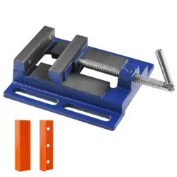
Low Profile Vise
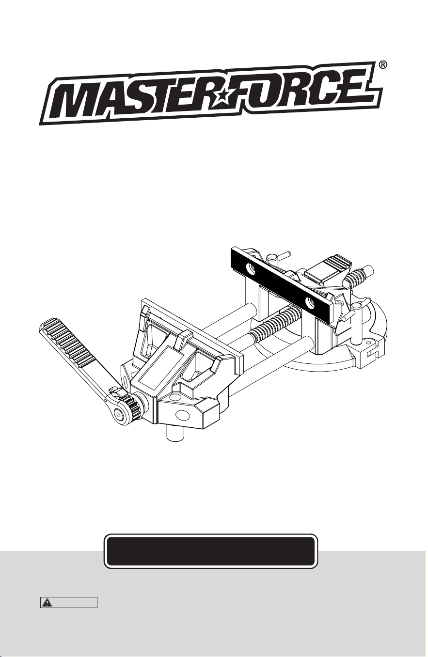
OPERATOR’S MANUAL
To Reduce The Risk Of Injury, User Must Read And
Understand Operator’s Manual. Save These Instructions For Future Reference.
CAUTION:
© 2018 Menard, Inc., Eau Claire, WI 54703 05/23/2018
243-1493, 243-1494
243-1495, 243-1496

Save this Manual..............................................................................
Safety Instructions............................................................................
Assembling the Handle....................................................................
Mounting the Vise.............................................................................
Operation..........................................................................................
Parts List...........................................................................................
Maintenance.....................................................................................
Notes................................................................................................
Warranty...........................................................................................
Page 1
Page 1
Page 2
Page 2
Page 3
Page 4
Page 6
Page 7
Page 9
TABLE OF CONTENTS
Page 9
SAVE YOUR RECEIPTS
THIS WARRANTY IS VOID WITHOUT THEM
90-DAY MONEY BACK GUARANTEE
Low Profile Vise
WARRANTY
This MASTERFORCE
®
brand tool carries our 90-Day Money Back Guarantee.
If you are not completely satisfied with your MASTERFORCE
®
brand power tool for
any reason within ninety (90) days from the date of purchase, return the tool with your
original receipt to any MENARDS
®
retail store, and we will provide you a refund - no
questions asked.
LIFETIME LIMITED WARRANTY
This MASTERFORCE
®
brand tool carries our famous No Hassle Lifetime Limited
Warranty to the original purchaser. If, during normal use, this MASTERFORCE
®
power
tool breaks or fails due to a defect in material or workmanship, simply bring the tool with
the original sales receipt back to your nearest MENARDS
®
retail store. At its discretion,
MASTERFORCE
®
agrees to have the tool or any defective part(s) repaired or replaced
with the same or similar MASTERFORCE
®
product or part free of charge, within the
stated warranty period, when returned by the original purchaser with original sales
receipt. Not withstanding the foregoing, this lifetime limited warranty does not cover any
damage that has resulted from abuse or misuse of the Merchandise. This warranty: (1)
excludes expendable parts including but not limited to blades, brushes, belts, bits, light
bulbs, and/or batteries; (2) shall be void if this tool is used for commercial and/or rental
purposes; and (3) does not cover any losses, injuries to persons/property or costs. This
warranty does give you specific legal rights and you may have other rights, which vary
from state to state. Be careful, tools are dangerous if improperly used or maintained.
Seller’s employees are not qualified to advise you on the use of this merchandise. Any
oral representation(s) made will not be binding on seller or its employees. The rights
under this lifetime limited warranty are to the original purchaser of the merchandise and
may not be transferred to any subsequent owner. This lifetime limited warranty is in lieu
of all warranties, expressed or implied including warranties or merchantability and fitness
for a particular purpose. Seller shall not be liable for any special, incidental, or
consequential damages. The sole exclusive remedy against the seller will be for the
replacement of any defects as provided herein, as long as the seller is willing or able to
replace this product or is willing to refund the purchase price as provided above. For
insurance purposes seller is not allowed to demonstrate any of these power tools for you.
For questions / comments, technical assistance or repair parts -
Please call toll free at: 1-800-255-7011 (M-F 8am - 6pm CST)

Reference this manual for all safety warnings and precautions, operating and maintenance
procedures, parts list and diagrams. Keep your invoice with this manual and write your invoice
number on the inside of the front cover. Keep the manual and invoice in a safe, dry place for
future reference.
Be sure to read and understand all safety instructions in this manual, including all safety alert
symbols such as "danger'', "warning", and "caution", before using this vise. Failure to follow all
instructions may result in serious personal injury.
WARNING:
NOTES
SAVE THIS MANUAL
1. Mount only according to these instructions. Improper mounting can create hazards.
2. Keep work area clean and well lit.
3. Keep bystanders out of the area during use.
4. This product is not a toy. Do not allow children to play with or near this item.
5. Use for intended purposes only.
6. Inspect before use; do not use if parts are loose or damaged.
7. Maintain product labels and nameplates. These carry important safety information.
If unreadable or missing, contact 1-800-255-7011 for a replacement.
8. Before drilling vise mounting holes, check for hidden electrical wires or cords in drilling path.
9. Medications may impair judgment and reflexes, so please read all safety warning labels on
medical prescriptions to determine if you may be affected. Do not use this product if you
are under the influence of drugs or alcohol.
10. Use eye and hand protection. Wear ANSI-approved safety impact goggles and heavy-duty
work gloves during use.
11. DRESS SAFELY. Do not wear loose clothing or jewelry as they can become caught in
moving parts. Wear a protective hair covering to prevent long hair from becoming caught in
the moving parts.
12. Do not overreach. Keep proper footing and balance at all times.
13. Stay alert. Watch what you are doing at all times. Use common sense. Do not operate this
product when you are tired or distracted from the job at hand.
14. Damage could occur to your vise and/or workpiece if you overtighten the handle.
SAFETY INSTRUCTIONS
Page 1Page 8
NOTE
Please heed the following safety warnings and precautions:

1. Remove the contents from the box and lay out on an even surface.
2. Remove the ratcheting handle, (3) selector switch, (10) ratcheting handle gear, (16) and
the ratcheting handle screw, (13) from the poly bag included in the vise box.
3. Center the selector switch, (10) with one hand and place the ratcheting handle gear, (16)
in between the tines of the ratcheting handle, (3).
4. While holding this assembly, (step 3 above) slide the ratcheting handle, (3) and the
ratcheting handle gear, (16) onto the end of the ACME screw, (11).
5. After the assembly is complete, screw in the Ratcheting Handle Screw (13) using a
5mm hex key.
6. Be careful not to overtighten the screw in the handle assembly.
15. Carefully check for damaged parts or any other conditions that may affect operation before
using this product. Repair or replace damaged and worn components immediately.
16. When servicing, use only identical, manufacturer-recommended replacement parts.
17. Maintain product with care. Keep this product clean and dry, and all moving parts lightly
lubricated for better performance. Keep the handle dry, clean and free from oil, grease,
and solvents.
18. Use the right tool for the job. Do not attempt to force a small tool or attachment to do the
work of a larger industrial tool. This vise was designed for specific applications. Do not
modify this tool or use it for any purpose other than that for which it was intended.
Page 7
ASSEMBLING THE HANDLE
MOUNTING THE VISE
Page 2
1. Select a solid, level mounting surface capable of supporting the combined weight of the
vise, intended workpieces and applicable forces.
2. Unlatch the Swivel Base Casting (14) and remove the Posi-Clock Disc (8).
3. Place the Posi-Clock Disc (8) onto your intended mounting surface.
4. Locate the “0” on your Posi-Clock Disc (8) and mount onto your bench in the
desired orientation.
5. Use the holes in the Posi-Clock Disc (8) as a template to mark the bench surface. With a
pencil trace the inside of the machined holes.
6. Remove the Posi-Clock Disc (8) and drill holes for mounting hardware (not included).
Be sure to pre-fit the bolts into the swivel Posi-Clock Disc (8) to insure the head of the
bolt fits into the counter bore. The head of the bolt cannot rest above the surface of the
plate, as it will not allow the vise to be mounted to the Posi-Clock Disc (8).
NOTES

1. To adjust the opening of the vise clamping pads, loosen the T-style Swivel Base Locks (5)
located on either side of the adjustable Swivel Base Casting (14). Grasp the Ratcheting
Handle (3) firmly with one hand and the Swivel Base Casting (14) with the other to rotate the
entire vise to your desired position. Once the orientation of the vise has been finalized,
screw down both of the T-style Swivel Base Locks (5) until they’re engaged into the
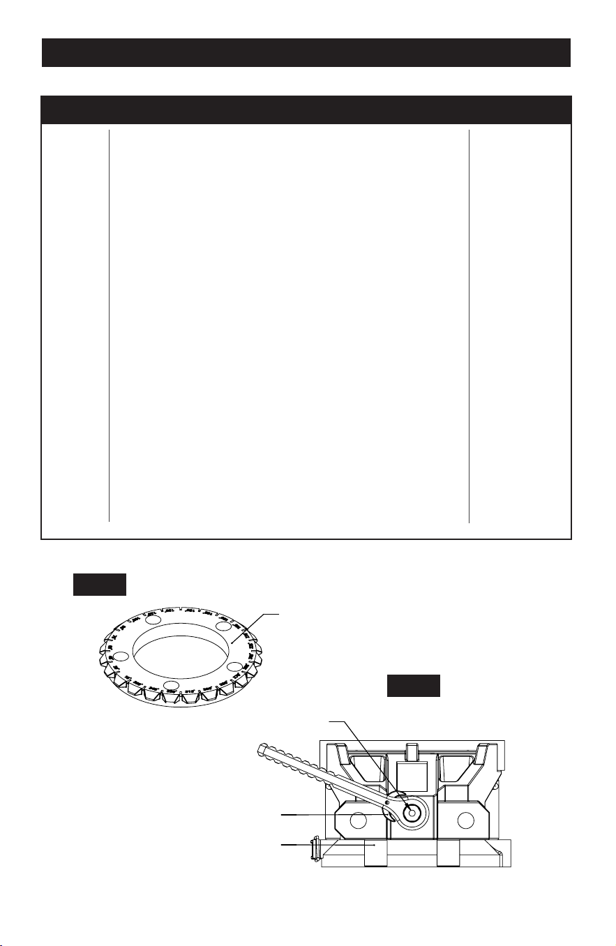
“V-shaped” channels located along the outer edge of the Posi-Clock Disc (8). SEE FIGURE 1.
The vise should be firmly fixed into the desired position. If the vise still moves, slightly rotate
the vise in either direction until the vise locks into place.
2. To quickly adjust the opening of the vise, depress the Speed Jaw™ Release Button (4) with
one hand while pulling on the Ratcheting Handle (3) with the other hand. The handle should
be in the up position. This will rapidly open and or close the jaws to the desired width.
3. To tighten the Serrated Jaws (7), depress the Selector Switch (10) to the left and begin
moving the Ratcheting Handle, (3) in a clockwise direction until a satisfactory grip is
achieved. DO NOT OVERTIGHTEN. At no point should you use an extended pipe, tube or
hammer to decrease the amount of force applied to the adjustable Ratcheting Handle, (3)
as it will damage the vise.
4. To loosen the Serrated Jaws (7), depress the Selector Switch (10) to the right and begin
moving the Ratcheting Handle, (3) in a counter-clockwise direction. At no point should you
use an extended pipe, tube or hammer to decrease the amount of force applied to the
adjustable Ratcheting Handle, (3) as it will damage the vise.
5. Should the user decide to remove the Swivel Base Casting (14) and mount directly to a
bench top, the Cast Body Attachment Screws (9) can be removed (4pcs). At this point, the
vise can be attached to the bench using the set of holes for the Cast Body Attachment
Screws (9) in either in Portion A or Portion B of the vise. SEE FIGURE 4.
7. Align bolt mounting holes with drilled holes then attach the Posi-Clock Disc (8) to your
surface using attaching screws (not included) being sure not to overtighten. All five
mounting points should have mounting hardware applied.
8. Unlatch the Swivel Base Lock (5) to the point where it will not interfere with the Posi-Clock
Disc (8) when installing the vise.
9. Slide the Swivel Base Casting (14) portion of the vise over the Posi-Clock Disc (8) and latch
the base closed using the Swivel Base Latch (6).
Page 3
OPERATION
Page 6
1. Avoid using solvents when cleaning.
2. Most items are susceptible to damage from various types of commercial solvents.
3. Use clean cloths to remove dirt, dust, oil, grease, etc.
4. Lubricate regularly.
MAINTENANCE
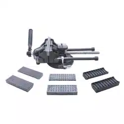
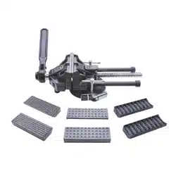
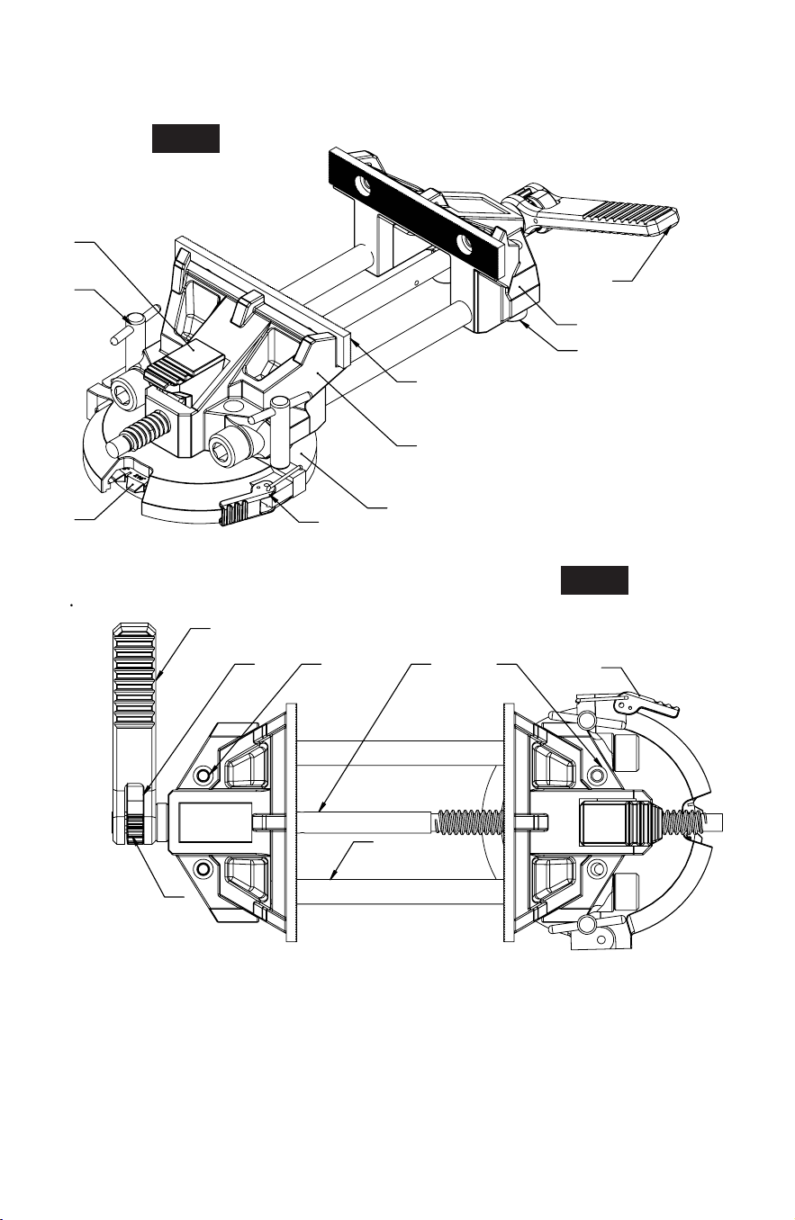
Cast Body Portion A
Cast Body Portion B
Ratcheting Handle
SPEEDJAW
™
Release Button
Swivel Base Lock
Swivel Base Latch
Serrated Jaws
Posi-Clock Disc
Cast Body Attachment Screw
Selector Switch
Acme Screw
Large Vise Bolts
Ratchet Handle Screw
Swivel Base Casting
Cast Body Support Rods
Ratcheting Handle Gear
1 pcs
1 pcs
1 pcs
1 pcs
2 pcs
1 pcs
2 pcs
1 pcs
4 pcs
1 pcs
1 pcs
2 pcs
1 pcs
1 pcs
2 pcs
1 pcs
DESCRIPTION QTYPART #
1
2
3
4
5
6
7
8
9
10
11
12
13
14
15
16
Page 5
PARTS LIST
Page 4
13
10
15
8
1
2
3
4
5
6
7
8
14
15
9 910 11
12
3
6
16
FIG 1
FIG 2
FIG 3
FIG 4
Portion A Portion B

1. To adjust the opening of the vise clamping pads, loosen the T-style Swivel Base Locks (5)
located on either side of the adjustable Swivel Base Casting (14). Grasp the Ratcheting
Handle (3) firmly with one hand and the Swivel Base Casting (14) with the other to rotate the
entire vise to your desired position. Once the orientation of the vise has been finalized,
screw down both of the T-style Swivel Base Locks (5) until they’re engaged into the
“V-shaped” channels located along the outer edge of the Posi-Clock Disc (8). SEE FIGURE 1.
The vise should be firmly fixed into the desired position. If the vise still moves, slightly rotate
the vise in either direction until the vise locks into place.
2. To quickly adjust the opening of the vise, depress the Speed Jaw™ Release Button (4) with
one hand while pulling on the Ratcheting Handle (3) with the other hand. The handle should
be in the up position. This will rapidly open and or close the jaws to the desired width.
3. To tighten the Serrated Jaws (7), depress the Selector Switch (10) to the left and begin
moving the Ratcheting Handle, (3) in a clockwise direction until a satisfactory grip is
achieved. DO NOT OVERTIGHTEN. At no point should you use an extended pipe, tube or
hammer to decrease the amount of force applied to the adjustable Ratcheting Handle, (3)
as it will damage the vise.
4. To loosen the Serrated Jaws (7), depress the Selector Switch (10) to the right and begin
moving the Ratcheting Handle, (3) in a counter-clockwise direction. At no point should you
use an extended pipe, tube or hammer to decrease the amount of force applied to the
adjustable Ratcheting Handle, (3) as it will damage the vise.
5. Should the user decide to remove the Swivel Base Casting (14) and mount directly to a
bench top, the Cast Body Attachment Screws (9) can be removed (4pcs). At this point, the
vise can be attached to the bench using the set of holes for the Cast Body Attachment
Screws (9) in either in Portion A or Portion B of the vise. SEE FIGURE 4.
7. Align bolt mounting holes with drilled holes then attach the Posi-Clock Disc (8) to your
surface using attaching screws (not included) being sure not to overtighten. All five
mounting points should have mounting hardware applied.
8. Unlatch the Swivel Base Lock (5) to the point where it will not interfere with the Posi-Clock
Disc (8) when installing the vise.
9. Slide the Swivel Base Casting (14) portion of the vise over the Posi-Clock Disc (8) and latch
the base closed using the Swivel Base Latch (6).
Page 3
OPERATION
Page 6
1. Avoid using solvents when cleaning.
2. Most items are susceptible to damage from various types of commercial solvents.
3. Use clean cloths to remove dirt, dust, oil, grease, etc.
4. Lubricate regularly.
MAINTENANCE

1. Remove the contents from the box and lay out on an even surface.
2. Remove the ratcheting handle, (3) selector switch, (10) ratcheting handle gear, (16) and
the ratcheting handle screw, (13) from the poly bag included in the vise box.
3. Center the selector switch, (10) with one hand and place the ratcheting handle gear, (16)
in between the tines of the ratcheting handle, (3).
4. While holding this assembly, (step 3 above) slide the ratcheting handle, (3) and the
ratcheting handle gear, (16) onto the end of the ACME screw, (11).
5. After the assembly is complete, screw in the Ratcheting Handle Screw (13) using a
5mm hex key.
6. Be careful not to overtighten the screw in the handle assembly.
15. Carefully check for damaged parts or any other conditions that may affect operation before
using this product. Repair or replace damaged and worn components immediately.
16. When servicing, use only identical, manufacturer-recommended replacement parts.
17. Maintain product with care. Keep this product clean and dry, and all moving parts lightly
lubricated for better performance. Keep the handle dry, clean and free from oil, grease,
and solvents.
18. Use the right tool for the job. Do not attempt to force a small tool or attachment to do the
work of a larger industrial tool. This vise was designed for specific applications. Do not
modify this tool or use it for any purpose other than that for which it was intended.
Page 7
ASSEMBLING THE HANDLE
MOUNTING THE VISE
Page 2
1. Select a solid, level mounting surface capable of supporting the combined weight of the
vise, intended workpieces and applicable forces.
2. Unlatch the Swivel Base Casting (14) and remove the Posi-Clock Disc (8).
3. Place the Posi-Clock Disc (8) onto your intended mounting surface.
4. Locate the “0” on your Posi-Clock Disc (8) and mount onto your bench in the
desired orientation.
5. Use the holes in the Posi-Clock Disc (8) as a template to mark the bench surface. With a
pencil trace the inside of the machined holes.
6. Remove the Posi-Clock Disc (8) and drill holes for mounting hardware (not included).
Be sure to pre-fit the bolts into the swivel Posi-Clock Disc (8) to insure the head of the
bolt fits into the counter bore. The head of the bolt cannot rest above the surface of the
plate, as it will not allow the vise to be mounted to the Posi-Clock Disc (8).
NOTES

Reference this manual for all safety warnings and precautions, operating and maintenance
procedures, parts list and diagrams. Keep your invoice with this manual and write your invoice
number on the inside of the front cover. Keep the manual and invoice in a safe, dry place for
future reference.
Be sure to read and understand all safety instructions in this manual, including all safety alert
symbols such as "danger'', "warning", and "caution", before using this vise. Failure to follow all
instructions may result in serious personal injury.
WARNING:
NOTES
SAVE THIS MANUAL
1. Mount only according to these instructions. Improper mounting can create hazards.
2. Keep work area clean and well lit.
3. Keep bystanders out of the area during use.
4. This product is not a toy. Do not allow children to play with or near this item.
5. Use for intended purposes only.
6. Inspect before use; do not use if parts are loose or damaged.
7. Maintain product labels and nameplates. These carry important safety information.
If unreadable or missing, contact 1-800-255-7011 for a replacement.
8. Before drilling vise mounting holes, check for hidden electrical wires or cords in drilling path.
9. Medications may impair judgment and reflexes, so please read all safety warning labels on
medical prescriptions to determine if you may be affected. Do not use this product if you
are under the influence of drugs or alcohol.
10. Use eye and hand protection. Wear ANSI-approved safety impact goggles and heavy-duty
work gloves during use.
11. DRESS SAFELY. Do not wear loose clothing or jewelry as they can become caught in
moving parts. Wear a protective hair covering to prevent long hair from becoming caught in
the moving parts.
12. Do not overreach. Keep proper footing and balance at all times.
13. Stay alert. Watch what you are doing at all times. Use common sense. Do not operate this
product when you are tired or distracted from the job at hand.
14. Damage could occur to your vise and/or workpiece if you overtighten the handle.
SAFETY INSTRUCTIONS
Page 1Page 8
NOTE
Please heed the following safety warnings and precautions:

Save this Manual..............................................................................
Safety Instructions............................................................................
Assembling the Handle....................................................................
Mounting the Vise.............................................................................
Operation..........................................................................................
Parts List...........................................................................................
Maintenance.....................................................................................
Notes................................................................................................
Warranty...........................................................................................
Page 1
Page 1
Page 2
Page 2
Page 3
Page 4
Page 6
Page 7
Page 9
TABLE OF CONTENTS
Page 9
SAVE YOUR RECEIPTS
THIS WARRANTY IS VOID WITHOUT THEM
90-DAY MONEY BACK GUARANTEE
Low Profile Vise
WARRANTY
This MASTERFORCE
®
brand tool carries our 90-Day Money Back Guarantee.
If you are not completely satisfied with your MASTERFORCE
®
brand power tool for
any reason within ninety (90) days from the date of purchase, return the tool with your
original receipt to any MENARDS
®
retail store, and we will provide you a refund - no
questions asked.
LIFETIME LIMITED WARRANTY
This MASTERFORCE
®
brand tool carries our famous No Hassle Lifetime Limited
Warranty to the original purchaser. If, during normal use, this MASTERFORCE
®
power
tool breaks or fails due to a defect in material or workmanship, simply bring the tool with
the original sales receipt back to your nearest MENARDS
®
retail store. At its discretion,
MASTERFORCE
®
agrees to have the tool or any defective part(s) repaired or replaced
with the same or similar MASTERFORCE
®
product or part free of charge, within the
stated warranty period, when returned by the original purchaser with original sales
receipt. Not withstanding the foregoing, this lifetime limited warranty does not cover any
damage that has resulted from abuse or misuse of the Merchandise. This warranty: (1)
excludes expendable parts including but not limited to blades, brushes, belts, bits, light
bulbs, and/or batteries; (2) shall be void if this tool is used for commercial and/or rental
purposes; and (3) does not cover any losses, injuries to persons/property or costs. This
warranty does give you specific legal rights and you may have other rights, which vary
from state to state. Be careful, tools are dangerous if improperly used or maintained.
Seller’s employees are not qualified to advise you on the use of this merchandise. Any
oral representation(s) made will not be binding on seller or its employees. The rights
under this lifetime limited warranty are to the original purchaser of the merchandise and
may not be transferred to any subsequent owner. This lifetime limited warranty is in lieu
of all warranties, expressed or implied including warranties or merchantability and fitness
for a particular purpose. Seller shall not be liable for any special, incidental, or
consequential damages. The sole exclusive remedy against the seller will be for the
replacement of any defects as provided herein, as long as the seller is willing or able to
replace this product or is willing to refund the purchase price as provided above. For
insurance purposes seller is not allowed to demonstrate any of these power tools for you.
For questions / comments, technical assistance or repair parts -
Please call toll free at: 1-800-255-7011 (M-F 8am - 6pm CST)

Low Profile Vise
OPERATOR’S MANUAL
To Reduce The Risk Of Injury, User Must Read And
Understand Operator’s Manual. Save These Instructions For Future Reference.
CAUTION:
© 2018 Menard, Inc., Eau Claire, WI 54703 05/23/2018
243-1493, 243-1494
243-1495, 243-1496