
Loading ...
Loading ...
Loading ...
ENGLISH
www.stiebel-eltron.com WWK222-302 H | 15
INSTALLATION
Installation
Following a one-off activation (signal is present for at least 1min-
ute), set temperature2 applies for at least 20minutes. Set temper-
ature2 is ranked higher than set temperature1. When the relevant
set DHW temperature has been reached, the compressor switches
off and remains off for a minimum idle time of 20minutes.
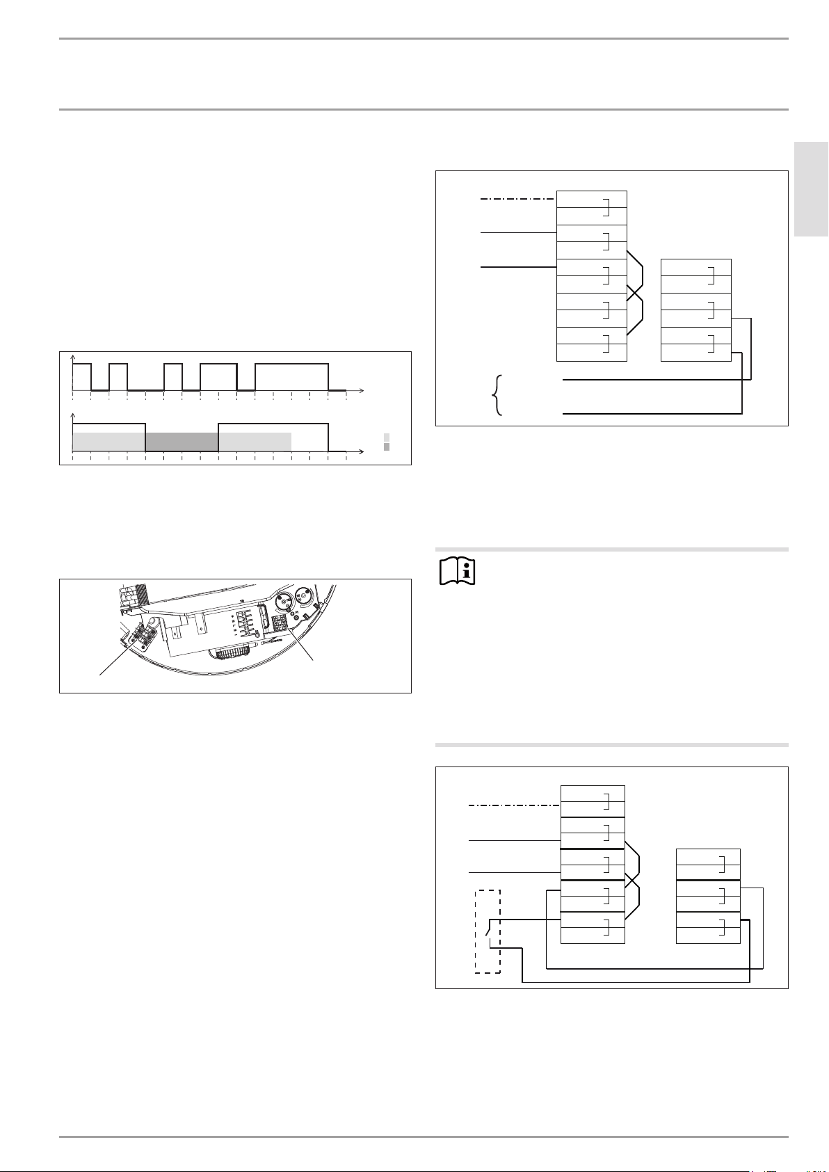
The following diagram illustrates the connections by means of a
sample signal sequence of an external signal transmitter.
Example:
- Water temperature = 62°C
- Set temperature 1 = 61°C
- Set temperature 2 = 65°C
A
1
0
0 5 10 15 20 25 30 35 40 45 50 55 60 65 70 75 t [min]
B
1
1
0 2
0 5 10 15 20 25 30 35 40 45 50 55 60 65 70 75 t [min]
D0000034613
A External signal
B Compressor
1 20 min. minimum runtime, set temperature2
2 20 min. minimum compressor idle time
Remove the appliance cover (see chapter "Cleaning and
maintenance/ Removing the appliance cover").
D0000056083
1
2
1 Strain relief
2 Terminal X3
Prepare the electric cables in such a way that each cable ter-
minates with a wire ferrule.
Push the cables through one of the cable entries in the appli-
ance casing.
Route leads through the strain relief.
Connect the cables to X3.
Example 1: Power-OFF signal with its own phase
X0
2
L
L
N
N
PE
PE
L
N
PE
GNYE
BU
BN
1
1
2
X3
2
3
3
1
1
2
L1 / L2 / L3
N
EVU
D0000059154
EVU power supply utility
BN brown
BU blue
GNYE green/yellow
Example 2: Photovoltaic signal via on-site relay and phase
routed outside the appliance
Note
The relay in the inverter must meet the following re-
quirements:
- Potential-free relay (240VAC / 24VDC, 1A) with
N/O contact
- Adherence to safety regulations and standards for
safety extra low voltage
- The switching output must be programmed so that
the relay contact closes or opens if certain limits are
exceeded or undershot (inverter output level).
If necessary, check with the inverter manufacturer wheth-
er the product meets the stated criteria.
X0
2
L
L
N
N
PE
PE
L
N
PE
GNYE
BU
BN
1
1
2
1
X3
2
3
3
1
1
2
D0000059155
1 Inverter (floating contact)
BN brown
BU blue
GNYE green/yellow
The inverter power feed is typically located at a central distribution
point (e.g. in the main fuse box).
Loading ...
Loading ...
Loading ...