Loading ...
Loading ...
Loading ...
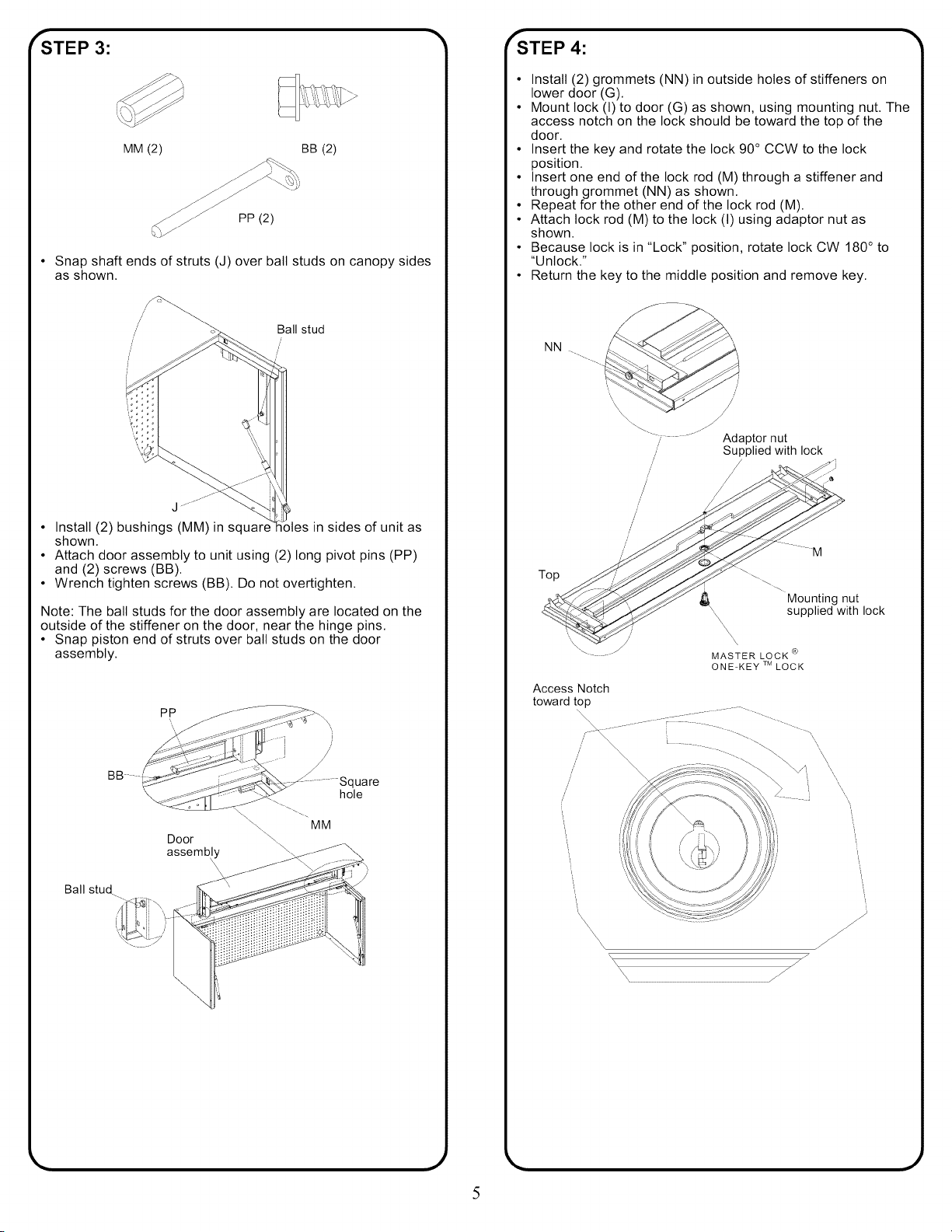
_'STEP 3:
MM (2) BB (2)
PP (2)
Snap shaft ends of struts (J) over ball studs on canopy sides
as shown.
//
/
/
Ball stud
d
• Install (2) bushings (MM) in square in sides of unit as
shown.
• Attach door assembly to unit using (2) long pivot pins (PP)
and (2) screws (BB).
• Wrench tighten screws (BB). Do not overtighten.
Note: The ball studs for the door assembly are located on the
outside of the stiffener on the door, near the hinge pins.
• Snap piston end of struts over ball studs on the door
assembly.
Ball stud
PP
Door
assembly
quare
hole
/
fSTEP 4: "_
• Install (2) grommets (NN)in outside holes of stiffeners on
lower door (G).
• Mount lock (I) to door (G) as shown, using mounting nut. The
access notch on the lock should be toward the top of the
door.
• Insert the key and rotate the lock 90° CCW to the lock
position.
• Insert one end of the lock rod (M) through a stiffener and
through grommet (NN) as shown.
• Repeat for the other end of the lock rod (M).
• Attach lock rod (M) to the lock (I) using adaptor nut as
shown.
• Because lock is in "Lock" position, rotate lock CW 180° to
"Unlock."
• Return the key to the middle position and remove key.
NN
-- _............ _,_^'4a_÷or
nut
/'
/ Supplied with lock
/
/'
Top
Access Notch
toward t_
/
/
f
_"\\\\\\\\
M
Mounting nut
supplied with lock
\\\\\\\\
MASTER LOCK ®
ONE-KEY TMLOCK
\\ //
\\\ ///
_11111 J
J
Loading ...
Loading ...
Loading ...