
Loading ...
Loading ...
Loading ...
English
12
5. UsE OF DUll OR DiRTY BlADEs
a. Dull blades cause increased loading of the saw. To
compensate, an operator will usually push harder
which further loads the unit and promotes twisting
of the blade in the kerf. Worn blades may also have
insufficient body clearance which increases the
chance of binding and increasedloading.
6. liFTing ThE sAW WhEn MAKing A BEVEl CUT
a. Bevel cuts require special operator attention to
proper cutting techniques – especially guidance of
the saw. Both blade angle to the shoe and greater
blade surface in the material increase the chance for
binding and misalignment (twist) tooccur.
7. REsTARTing A CUT WiTh ThE BlADE TEETh
JAMMED AgAinsT ThE MATERiAl
a. The saw should be brought up to full operating
speed before starting a cut or restarting a cut after
the unit has been stopped with the blade in the kerf.
Failure to do so can cause stalling andkickback.
Any other conditions which could result in pinching,
binding, twisting, or misalignment of the blade could cause
kickback. Refer to the sections Further Safety Instructions
for All Saws and Blades for procedures and techniques that
will minimize the occurrence ofkickback.
Cutting Depth Adjustment (Fig. A, J, K)
nOTE: The maximum depth of cut for this saw is 2-9/16"
(65mm) at 90°.
1. Hold the saw firmly and loosen (clockwise) the depth
adjustment lever
4
and move shoe (
5
, Fig.A) to obtain
the desired depth ofcut.
2. Make sure the depth adjustment lever has been
retightened (counterclockwise) before operatingsaw.
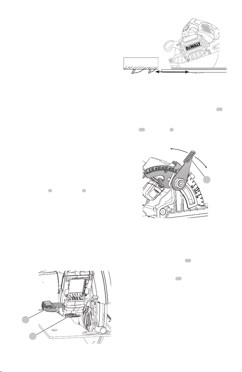
For the most efficient cutting action, set the depth
adjustment so that one-half tooth of the blade will project
below the material to be cut. This distance is from the tip of
the tooth to the bottom of the gullet in front of it. This keeps
blade friction at a minimum, removes sawdust from the cut,
results in cooler, faster sawing and reduces the chance of
kickback. A method for checking for correct cutting depth
is shown in FigureK. Lay a piece of the material you plan to
cut along the side of the blade, as shown, and observe how
much tooth projects beyond thematerial.
Fig. J
4
14
Fig. K
Bevel Angle Adjustment (Fig. A, L)
The full range of the bevel adjustment is from 0° to 57°. The
quadrant is graduated in increments of 1°. On the front of
the saw is a bevel angle adjustment mechanism consisting
of a calibrated quadrant and a bevel adjustment lever
10
.
To set the saw for a bevel cut
1. Loosen (counterclockwise) the bevel adjustment
lever
10
and tilt shoe (
5
, Fig.A) to the desired angle by
aligning the pointer with the desired anglemark.
2. Retighten lever firmly (clockwise).
Fig. L
10
Shoe Adjustment for 90°Cuts (Fig. L, M)
If additional adjustment is needed:
1. Adjust the saw to 0°bevel.
2. Retract the lower blade guard. Place the saw on
bladeside.
3. Loosen bevel adjustment lever (
10
, Fig.L). Place
a square against the blade and shoe to adjust the
90°setting.
4. Turn the calibration screw
18
so that the shoe will stop
at the properangle.
5. Confirm the accuracy of the setting by checking the
squareness of an actual cut on a scrap piece ofmaterial.
Loading ...
Loading ...
Loading ...