Loading ...
Loading ...
Loading ...
5 English
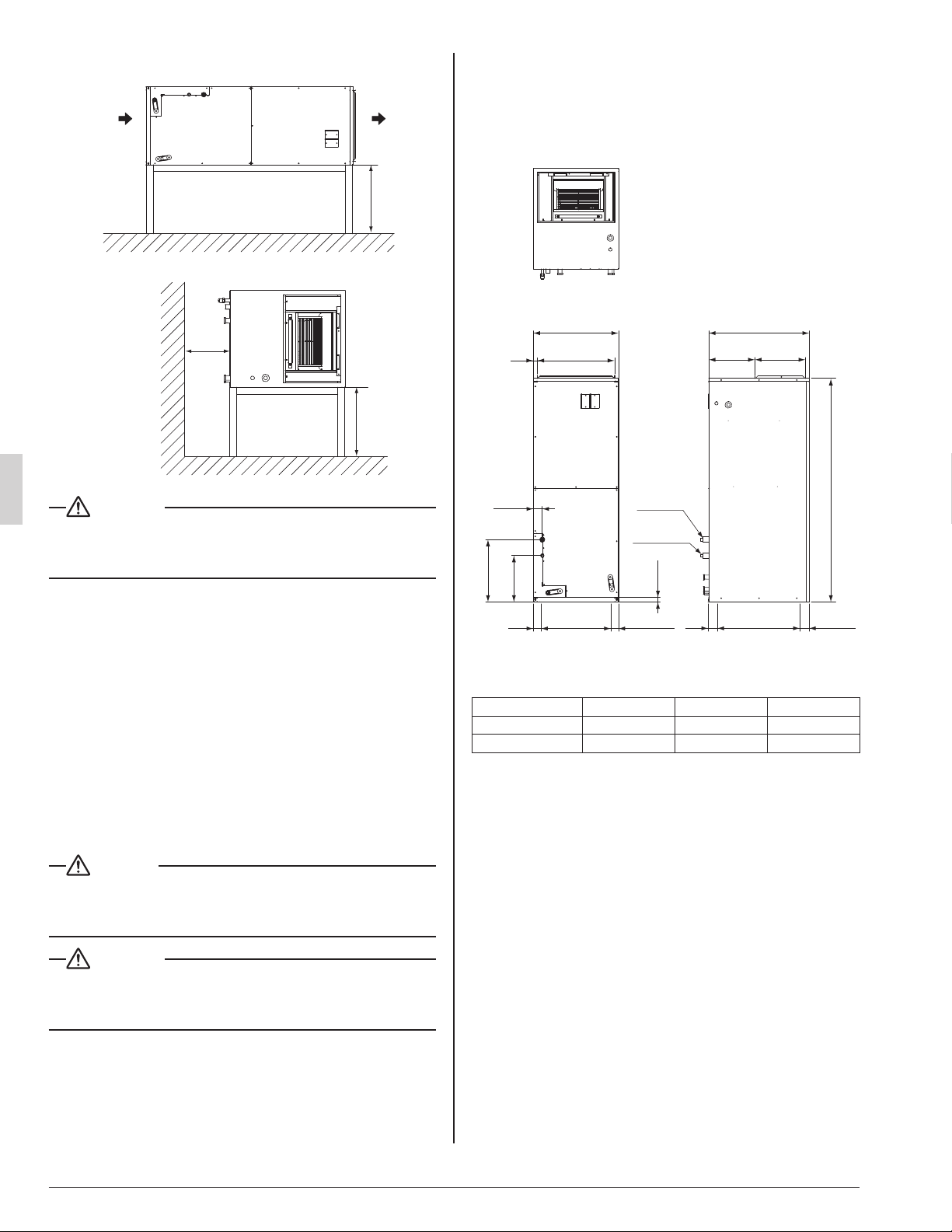
If installed horizontally
H
(Front view)
Air outlet
Air inlet
24 or
more
(Side view)
H
Fig. 1-2
WARNING
When installing the unit horizontally, be sure to tilt the unit in •
the direction shown in Fig. 1-2. If the unit is tilted in any other
way, water can leak.
Ensure suffi cient space for the bottom of the product
•
(H dimensions) so that a downward slope of 1/100 can
be maintained for drain piping, as described for the intake
duct installation and in “6. DRAIN PIPING WORK”.
[ PRECAUTION ]
Install the indoor and outdoor units, power supply wiring •
and connecting wires at least 3.5 ft. away from televi-
sions or radios in order to prevent image interference or
noise. (Depending on the radio waves, a distance of
3.3 ft. may not be suffi cient to eliminate the noise.)
If installing the wireless kit in a room with electronic •
fl uorescent lighting (inverter or rapid start type), the
remote controller’s transmission distance may be short-
ened. Indoor units should be installed as far away from
fl uorescent lighting as possible.
DANGER
Do not install unit in an area where fl ammable materials are •
present due to the risk of an explosion resulting in serious
injury or death.
WARNING
If the supporting structural members are not strong enough •
to take the unit’s weight, the unit could fall out of place and
cause serious injury.
PREPARATIONS BEFORE INSTALLA-4.
TION AND INSTALLATION
When installing the product, refer to “3. SELECTING (1)
INSTALLATION SITE” and consider the product size
as shown Fig. 2 and Table 1.
20
22
13-1/16
12
26
A
B
C
1-1/4
Gas line
182 (2)
1
2-1/4
20-11/163
(2-5/16)
Liquid line
Inlet
Inlet
(Right side view)
(Front view)
(unit: in.)
Fig. 2
Table 1
ABC
FTQ30 - 42
58-1/4 16-1/4 12-1/16
FTQ18 - 24 48-1/8 13-3/16 9-1/16
Make sure the range of the unit’s external static pres-(2)
sure is not exceeded. (up to 0.5 in.WG at “HH” speed.)
01_EN_3P250363-4E.indd 501_EN_3P250363-4E.indd 5 6/9/2016 4:56:43 PM6/9/2016 4:56:43 PM
Loading ...
Loading ...
Loading ...