Loading ...
Loading ...
Loading ...
9 English
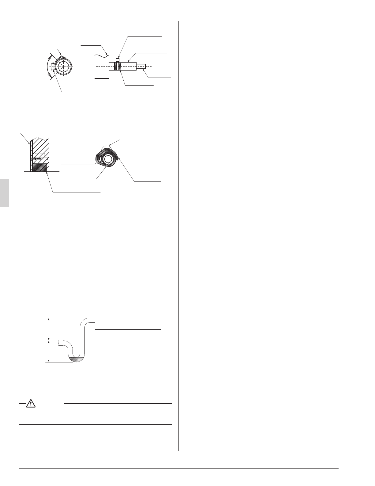
Tape section
VP25 side
Metal clamp (4)
(accessory)
Drain hose (5)
(accessory)
Tightening
section
Bend the end to avoid
tearing the Sealing
pad (large) (9).
Approx. 90°
Main unit
<When bending the end>
Refer to the following fi gure and check the drain. Then, •
use the included Sealing pad (large) (9) to thermally
insulate the Metal clamp (4) and the Drain hose (5).
Do not make any gap
Drain hose (5)
Sealing pad
(large) (9)
Sealing pad
(large) (9)
<Drain socket thermal insulation work>
(accessory)
(accessory)
(accessory)
Wrap the sealing
material around so
that the side with the
edge of the flat band is
doubly wrapped.
Start wrapping
from near the
tightening
section of the
Metal clamp (4)
The drain pan has connections for a primary and sec-•
ondary drain.
The diameter of the drain piping should be greater than •
or equal to the diameter of the connecting pipe (vinyl
tube; pipe size : 25/32 in. ; outer dimension : 1-1/32 in.).
(not including a riser)
Keep piping runs short with a downward slope of at •
least 1/100 to prevent air pocket from forming.
Be sure to install a drain trap at the drain outlet since •
the inside of the unit is at negative pressure relative to
atmospheric pressure during operation.
To keep the piping from becoming clogged with dirt, •
avoid bends where possible and install so that traps can
be cleaned.
Air handler
At least
4 in.
At least
3 in.
Observe the following guidelines when installing con-•
centrated drain piping. Select the thickness of the
concentrated drain piping to refl ect the capacity of the
machine to which it will be connected.
CAUTION
Water accumulating in the drain piping can cause the drain •
to clog.
〈PRECAUTIONS〉
Drain piping connections
Do not connect the drain piping directly to sewage piping •
that smell of ammonia. The ammonia in the sewage might
enter the indoor unit through the drain piping and corrode
the heat exchanger.
Do not twist or bend the drain hose, as excessive force may •
cause it to leak.
After piping work is fi nished, check drainage fl ows (2)
smoothly.
Gradually insert approximately 1 quart of water into the •
drain pan to check drainage in the manner described
below.
INSTALLING THE DUCT7.
Exercise care regarding the following when performing duct work.
Verify that duct work does not exceed the unit’s setting range
•
of external static pressure (up to 0.5 in.WG at “HH” speed).
Install canvas ducts at air outlets and inlets so that vibrations •
from the main unit are not transmitted to ducts or the fl oor.
Additionally, line the duct with sound-absorbing material
(heat insulation material) as necessary.
Be sure to install an air fi lter to the product’s air inlet or to a •
fi eld-supplied air inlet inside the air passage on the suction
side.
Perform the curing and other work during duct welding so •
that the inside of the product is not exposed to spatter.
If the metal duct passes through a metal lath, wire lath, or •
metal plate of a wooden structure, isolate the duct from the
wall electrically.
Be sure to heat-insulate the duct to prevent the formation of •
condensation. (Material: Glass wool or polyethylene foam;
thickness: 1 inch.)
Explain to the customer how to operate and clean fi eld-•
supplied components such as air fi lters, air inlet grilles, air
outlet grilles.
To prevent drafts, locate the air outlet grille on the indoor •
side so that warm air from the outlet does not come into
direct contact with room occupants.
When an electric heater (optional) is installed, use metal •
duct and wrap the duct with a glass-wool insulation material.
ELECTRIC WIRING WORK8.
GENERAL INSTRUCTIONS8-1
Shut off the power before doing any work.•
All fi eld supplied parts and materials, electric works must •
conform to local codes.
Use copper conductors only.•
See also the “Wiring Diagram Label” located inside the unit’s •
front cover.
For details on hooking up the remote controller, refer to the •
“REMOTE CONTROLLER INSTALLATION MANUAL”.
All wiring must be performed by an authorized electrician.•
Install a wiring interrupter or ground-fault circuit interrupter •
for the power wiring.
Make sure the ground resistance is no greater than 100• Ω.
To avoid short circuiting the power supply wire, be sure to •
use insulated terminals.
Do not turn on the power supply (wiring interrupter or •
ground-fault circuit interrupter) until all other work is done.
01_EN_3P250363-4E.indd 901_EN_3P250363-4E.indd 9 6/9/2016 4:56:49 PM6/9/2016 4:56:49 PM
Loading ...
Loading ...
Loading ...