
p/n: 614-21325
Revision 01
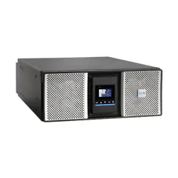
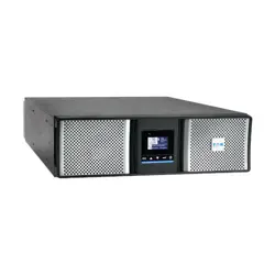
SU750RTXLCD2U
SU750RTXLCD2UN
SU1000RTXLCD2U
SU1000RTXLCD2UN
SU1500RTXLCD2U
SU1500RTXLCDN
SU2200RTXLCD2U
SU2200RTXLCDN
SU3000RTXLCD2U
SU3000RTXLCD2UN
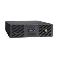
SUINT1000LCD2U
SUINT1500LCD2U
SUINT2200LCD2U
SUINT3000LCD2U
BP36RT
BP48RT
BP72RT
Rack / Tower Advanced Users Guide
Eaton Tripp Lite SmartOnline Series

©Copyright 2022 Eaton, Raleigh, NC, USA. All rights reserved. No part of this document may be reproduced in any way without the
express written approval of Eaton.
SSaaffeettyy IInnssttrruuccttiioonnss
SAVE THESE INSTRUCTIONS. This manual contains important instructions that should be
followed during installation and maintenance of the UPS and batteries.
This equipment has been tested and found to comply with the limits for a Class A digital device,
pursuant to Part 15 of the FCC Rules. These limits are designed to provide reasonable protection
against harmful interference when the equipment is operated in a commercial environment. This
equipment generates, uses, and can radiate radio frequency energy and, if not installed and used in
accordance with the instruction manual, may cause harmful interference to radio communications.
Operation of this equipment in a residential area is likely to cause harmful interference in which case
the user will be required to correct the interference at his own expense.
This is a category C2 UPS product. In a residential environment, this product may cause radio
interference, in which case the user may be required to take additional measures.
Supplier's Declaration of Conformity of Federal Communications Commission Statement
This device complies with Part 15 of the FCC Rules. Operation is subject to the following two
conditions:
1. this device may not cause harmful interference, and
2. this device must accept any interference received, including interference that may cause
undesired operation.
For questions regarding this FCC SDoC declaration, contact Eaton Corporation by telephone or
through the Internet.
Eaton Corporation 8609 Six Forks Road,
Raleigh, NC 27615, USA
Telephone: 800-356-5794
SSppeecciiaall SSyymmbboollss
The following are examples of symbols used on the product to alert you to important information:
RISK OF ELECTRIC SHOCK - Observe the warning associated with the risk of
electric shock symbol.
CAUTION: REFER TO OPERATOR'S MANUAL - Refer to your operator's
manual for additional information, such as important operating and maintenance
instructions.
This symbol indicates that you should not discard the UPS or the UPS batteries in
the trash. This product contains sealed lead acid batteries and must be disposed
of properly. For more information, contact your local recycling/reuse or hazardous
waste center.
Special Symbols
The following are examples of symbols used on the UPS or accessories to alert you to important
information:
RISK OF ELECTRIC SHOCK - Observe the warning associated with the risk of
electric shock symbol.
CAUTION: REFER TO OPERATOR'S MANUAL - Refer to your operator's manual for
additional information, such as important operating and maintenance
instructions.
This symbol indicates that you should not discard the UPS or the UPS batteries
in the trash. This product contains sealed, lead‐acid batteries and must be
disposed of properly. For more information, contact your local recycling/reuse or
hazardous waste center.
This symbol indicates that you should not discard waste electrical or electronic
equipment (WEEE) in the trash. For proper disposal, contact your local
recycling/reuse or hazardous waste center.
Eaton, Powerware, and BladeUPS are registered trademarks of Eaton Corporation or its subsidiaries and affiliates.
Phillips and Pozidriv are registered trademarks of Phillips Screw Company.
ECopyright 2008–2010 Eaton Corporation, Raleigh, NC, USA. All rights reserved. No part of this document may be
reproduced in any way without the express written approval of Eaton Corporation.
This symbol indicates that waste electrical and electronic equipment as well as
waste batteries and accumulators should not be discarded together with
unseparated household waste, but must be collected separately. The product
should be handed in for recycling in accordance with the local environmental
regulations for waste disposal. By separating waste electrical and electronic
equipment as well as waste batteries and accumulators, you will help reduce the
volume of waste sent for incineration or land-fills and minimize any potential
negative impact on human health and environment.
SSaaffeettyy ooff PPeerrssoonnss
• The system has its own power source (the battery). Consequently, the power outlets may be
energized ven if the systems is disconnected from the AC power source. Dangerous voltage
levels are resent within the system. It should be opened exclusively by qualified service
personnel.
• The system must be properly grounded at all times.
• The battery supplied with the system contains small amounts of toxic materials. To avoid
accidents, the directives listed below must be observed:
– Servicing of batteries should be performed or supervised by personnel knowledgeable about
batteries and the required precautions.
– When replacing batteries, replace with the same type and number of batteries or battery
packs.
– Do not dispose of batteries in a fire. The batteries may explode.
– Batteries constitute a danger (electrical shock, burns). The short-circuit current may be very
high.
• Precautions must be taken for all handling:
– Wear rubber gloves and boots.
– Do not lay tools or metal parts on top of batteries.
– Disconnect charging source prior to connecting or disconnecting battery terminals.
– Determine if battery is inadvertently grounded. If inadvertently grounded, remove source
from ground. Contact with any part of a grounded battery can result in electrical shock. The
likelihood of such shock can be reduced if such grounds are removed during installation and
maintenance (applicable to equipment and remote battery supplies not having a grounded
supply circuit).

PPrroodduucctt SSaaffeettyy
• To connect the UPS, instructions and operation described in the manual must be followed in the
indicated order.
• CAUTION - To reduce the risk of fire, the unit connects only to a circuit provided with 20 or 30
amperes maximum branch circuit overcurrent protection in accordance with the National Electric
Code, ANSI/NFPA 70 (US installations only).
• Check that the indications on the rating plate correspond to your AC powered system and to the
actual electrical consumption of all the equipment to be connected to the system.
• For PLUGGABLE EQUIPMENT, the socket-outlet shall be installed near the equipment and shall
be easily accessible
• Never install the system near liquids or in an excessively damp environment.
• Never let a foreign body penetrate inside the system.
• Never block the ventilation grates of the system.
• Never expose the system to direct sunlight or source of heat.
• If the system must be stored prior to installation, storage must be in a dry place.
• The admissible storage temperature range is -25ºC to +55ºC without batteries, 0°C to 40°C with
batteries.
• The system is not for use in a computer room AS DEFINED IN the standard for the Protection of
Information Technology Equipment, ANSI/NFPA 75 (US installations only).
SSppeecciiaall PPrreeccaauuttiioonnss
• The unit is heavy: wear safety shoes and use vacuum lifter preferentially for handling operations.
• All handling operations will require at least two people (unpacking, lifting, installation in rack
system).
• Before and after the installation, if the UPS remains de-energized for a long period, the UPS must
be energized for a period of 24 hours, at least once every 6 months (for a normal storage
temperature less than 25°C). This charges the battery, thus avoiding possible irreversible
damage.
• During the replacement of the Battery Module, it is imperative to use the same type and number
of element as the original Battery Module provided with the UPS to maintain an identical level of
performance and safety. If there are any questions, don’t hesitate to contact your local Eaton
representative.
• All repairs and service should be performed by AUTHORIZED SERVICE PERSONNEL ONLY.
There are NO USER SERVICEABLE PARTS inside the UPS.
• For potential safety issue on defective UPS : DISCONNECT INTERNAL BATTERY for storage and
transportation.

Tripp Lite by Eaton SmartOnline Series User Guide 614-21325—Rev 01 v
TTaabbllee ooff CCoonntteennttss
11 PPrreesseennttaattiioonn ..................................................................................................................................................................................................................................................................................................11
1.1 Introduction............................................................................................................................................... 1
1.2 Environmental Protection ............................................................................................................................. 1
1.3 Standard Installations .................................................................................................................................. 3
1.4 Rear Panels ...............................................................................................................................................4
22 IInnssttaallllaattiioonn ......................................................................................................................................................................................................................................................................................................77
2.1 Inspecting the Equipment.............................................................................................................................7
2.2 Checking the Accessory Kit ..........................................................................................................................7
2.3 Connecting the Internal Battery .....................................................................................................................9
2.3.1 UPS Tower Installation...........................................................................................................................9
2.3.2 UPS Rack Installation........................................................................................................................... 10
2.4 SmartOnline External Battery Pack Installation ................................................................................................ 11
2.4.1 External Battery Rackmount Installation................................................................................................... 11
2.4.2 Extended Battery Pack Rackmount Connections ....................................................................................... 12
2.4.3 UPS and Extended Battery Pack Tower Installation .................................................................................... 13
2.4.4 Extended Battery Pack Tower Connections .............................................................................................. 14
33 IInntteerrffaacceess aanndd CCoommmmuunniiccaattiioonn .......................................................................................................................................................................................................................................... 1155
3.1 Control Panel ........................................................................................................................................... 15
3.2 LCD Description ....................................................................................................................................... 16
3.3 UPS Home Menu ..................................................................................................................................... 17
3.4 Display Functions ..................................................................................................................................... 18
3.5 User Settings........................................................................................................................................... 20
3.6 Communication Ports ................................................................................................................................ 23
3.7 Remote Control Functions .......................................................................................................................... 24
3.8 Tripp Lite By Eaton PowerAlert Software Suite ............................................................................................... 28
3.9 Cybersecurity .......................................................................................................................................... 28
44 OOppeerraattiioonn........................................................................................................................................................................................................................................................................................................ 2299
4.1 Start-up and Normal operation ..................................................................................................................... 29
4.2 Starting the UPS on Battery ........................................................................................................................ 29
4.3 UPS Shutdown ........................................................................................................................................ 29
4.4 Operating Modes ..................................................................................................................................... 29
4.5 Return of AC Power .................................................................................................................................. 30
4.6 Setting High Efficiency mode ...................................................................................................................... 30
4.7 Configuring the Battery Settings .................................................................................................................. 31
4.8 Retrieving the Event Log ............................................................................................................................ 31
55 UUPPSS MMaaiinntteennaannccee................................................................................................................................................................................................................................................................................ 3333
5.1 Equipment Care ....................................................................................................................................... 33
5.2 Storing the Equipment ............................................................................................................................... 33

vi Tripp Lite by Eaton SmartOnline Series User Guide 614-21325—Rev 01
5.3 When to Replace Batteries ......................................................................................................................... 33
5.4 Replacing batteries ................................................................................................................................... 33
5.5 Recycling the used equipment .................................................................................................................... 36
66 TTrroouubblleesshhoooottiinngg .................................................................................................................................................................................................................................................................................... 3377
6.1 Typical Alarms and Faults ........................................................................................................................... 37
6.2 Silencing the Alarm ................................................................................................................................... 41
6.3 Service and Support .................................................................................................................................. 41
77 SSppeecciiffiiccaattiioonnss.......................................................................................................................................................................................................................................................................................... 4433
7.1 Model Specifications ................................................................................................................................. 43
Table of Contents

Tripp Lite by Eaton SmartOnline Series User Guide 614-21325—Rev 01 1
CChhaapptteerr 11 PPrreesseennttaattiioonn
11..11 IInnttrroodduuccttiioonn
Thank you for selecting an Tripp Lite by Eaton product to protect your electrical equipment.
The Tripp Lite by Eaton SmartOnline UPS range has been designed with the utmost care.
We recommend that you take the time to read this manual to take full advantage of the many features of your
UPS (Uninterruptible Power System).
Before installing your UPS, please read the booklet presenting the safety instructions. Then follow the
indications in this manual.
To discover the entire range of products and the options available for the Tripp Lite by Eaton SmartOnline UPS
range visit our web site at Tripp Lite.com or contact your Tripp Lite by Eaton representative.
11..22 EEnnvviirroonnmmeennttaall PPrrootteeccttiioonn
Tripp Lite by Eaton has implemented an environmental-protection policy.
Products are developed according to an eco-design approach.
Substances
This product does not contain CFCs, HCFCs, or asbestos.
Packing
To improve waste treatment and facilitate recycling, separate the various packing components.
• The cardboard we use comprises over 50% of recycled cardboard.
• Sacks and bags are made of polyethylene.
• Packing materials are recyclable and bear the appropriate identification symbol
01
PET
Table 1. Packing Material Symbols
Materials Abbreviations Number in the symbols
Polyethylene terephthalate PET
01
High-density polyethylene HDPE 02
Polyvinyl chloride PVC
03
Low-density polyethylene LDPE 04
Polypropylene PP 05
Polystyrene PS
06
Follow all local regulations for the disposal of packing materials.
End of Life
Tripp Lite by Eaton will process products at the end of their service life in compliance with local regulations.
Tripp Lite by Eaton works with companies in charge of collecting and eliminating our products at the end of
their service life.
Product

2 Tripp Lite by Eaton SmartOnline Series User Guide 614-21325—Rev 01
The product is mainly made up of recyclable materials.
Dismantling and destruction must take place in compliance with all local regulations concerning waste. At the
end of its service life, the product must be transported to a processing center for electrical and electronic
waste.
Battery
The product contains lead acid (Pb) batteries that must be processed according to applicable local regulations
concerning batteries.
The battery may be removed to comply with regulations and in view of correct disposal.
The Tripp Lite by Eaton SmartOnline power system (UPS) protects your sensitive electronic equipment from
the most common power problems, including power failures, power sags, power surges, brownouts, line
noise, high voltage spikes, frequency variations, switching transients, and harmonic distortion.
Power outages can occur when you least expect it and power quality can be erratic. These power problems
have the potential to corrupt critical data, destroy unsaved work sessions, and damage hardware causing hours
of lost productivity and expensive repairs.
With the Tripp Lite by Eaton SmartOnline power system, you can safely eliminate the effects of power
disturbances and guard the integrity of your equipment. Providing outstanding performance and reliability, the
Tripp Lite by Eaton SmartOnline power system unique benefits include:
• True online double-conversion technology with high power density, utility frequency independence, and
generator compatibility.
• Selectable High Efficiency mode of operation.
• Standard communication options: one RS-232 communication port, one USB communication port, and
relay output contacts.
• Optional connectivity cards with enhanced communication capabilities.
• Extended runtime with up to four Extended Battery Modules (EBMs) per UPS.
• Remote On/Off control through Remote On/Off (ROO) and Remote Power Off (RPO) ports.
• Backed by worldwide agency approvals.
Environmental Protection
Tripp Lite by Eaton SmartOnline Series User Guide 614-21325—Rev 01 3
11..33 SSttaannddaarrdd IInnssttaallllaattiioonnss
D
H
W
W
H
D
Table 2. Weights and Dimensions
Model
Weight (lb / kg) Dimensions D x W x H(inch/mm)
SU750RTXLCD2U / SU750RTXLCD2UN
36.4 / 16.5 17.7 x 17.3 x 3.4 / 450 x 440 x 86.5
SU1000RTXLCD2U / SU1000RTXLCD2UN 36.4 / 16.5 17.7 x 17.3 x 3.4 / 450 x 440 x 86.5
SU1500RTXLCD2U / SU1500RTXLCDN 42.5 / 19.3 17.7 x 17.3 x 3.4 / 450 x 440 x 86.5
SU2200RTXLCD2U / SU2200RTXLCDN 61.6 / 27.9 23.8 x 17.3 x 3.4 / 605 x 440 x 86.5
SU3000RTXLCD2U / SU3000RTXLCD2UN 63 / 28.6 23.8 x 17.3 x 3.4 / 605 x 440 x 86.5
SUINT1000LCD2U 36.4 / 16.5 17.7 x 17.3 x 3.4 / 450 x 440 x 86.5
SUINT1500LCD2U
41.4 / 18.8 17.7 x 17.3 x 3.4 / 450 x 440 x 86.5
SUINT2200LCD2U 59.7 / 27.1 23.8 x 17.3 x 3.4 / 605 x 440 x 86.5
SUINT3000LCD2U 61.2 / 27.8 23.8 x 17.3 x 3.4 / 605 x 440 x 86.5
BP36RT 48.1 / 21.8 17.7 x 17.3 x 3.4 / 450 x 440 x 86.5
BP48RT 59.5 / 27 17.7 x 17.3 x 3.4 / 450 x 440 x 86.5
BP72RT 86.4 / 39.2 23.8 x 17.3 x 3.4 / 605 x 440 x 86.5
Standard Installations
4 Tripp Lite by Eaton SmartOnline Series User Guide 614-21325—Rev 01
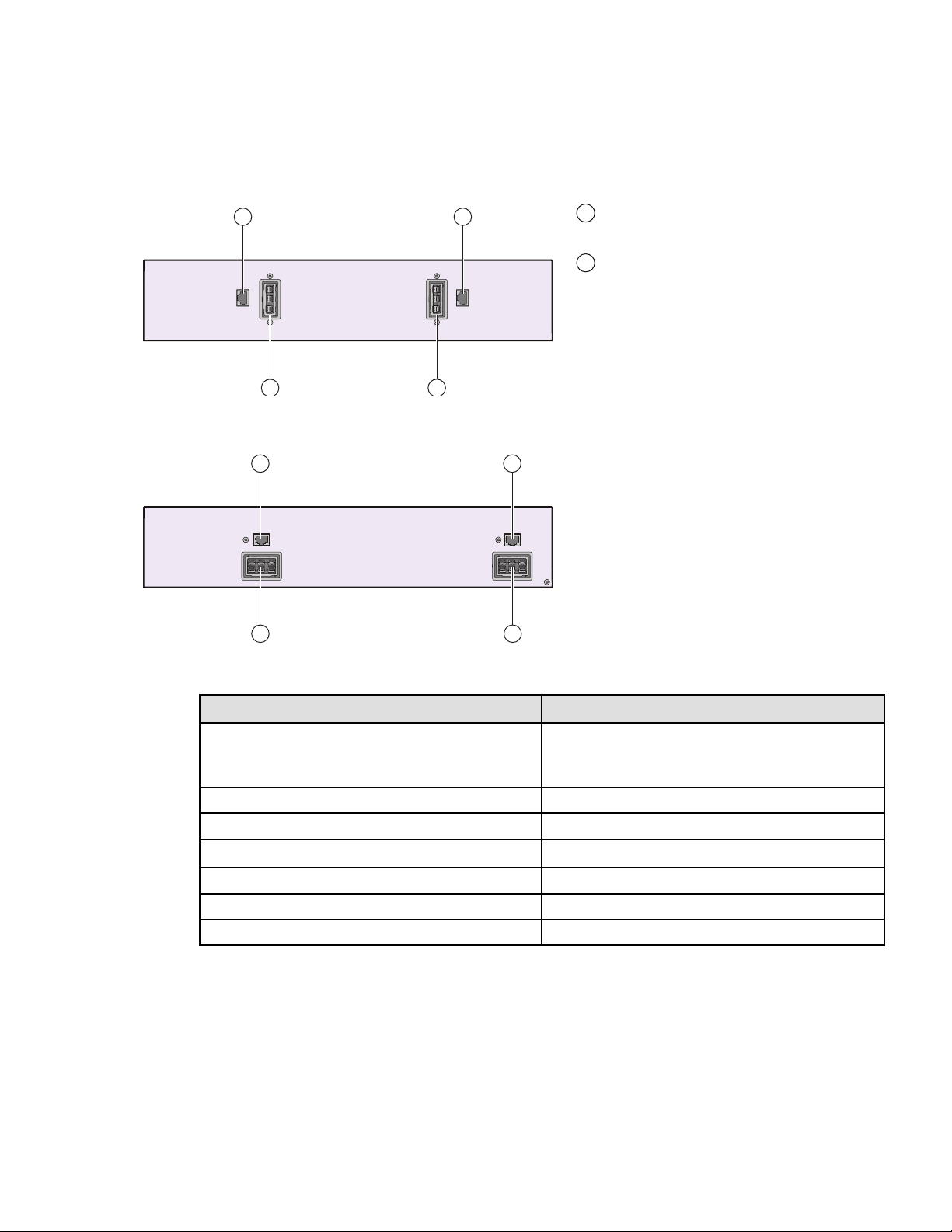
11..44 RReeaarr PPaanneellss
Figure 1. UPS Rear Panels
SU750RT / SU1000RT / SU1500RT
1 2 3 4 5 6
9 811 10 7
SU2200RT
1 82 43
5 6
9 1011 7
SU3000RT
SUINT2200RT / SUINT3000RT
1
Socket for connection to AC power
source
2
Slot for optional communication card
3
Relay output contact
4
Connector for additional battery
module
5
Primary group: outlets for
connection of critical equipment
6
Group 1: programmable
outlets for connection of equipment
7
Group 2: programmable
outlets for connection of equipment
8
Connector for automatic recognition
of an additional battery module
9
RS232 communication port
10
USB communication port
11
Connector for ROO (Remote On/Off)
control and RPO (Remote Power Off)
(*) Primary and Grouped outlets
(
5
,
6
,
7
) are protected by 20A
circuit breakers.
1 82 4 53
9 1011 6 7
1 82 43
5 6
9
1011
7
SUINT1000RT / SUINT1500RT
1 2 4 5
63891011 7
Rear Panels
Tripp Lite by Eaton SmartOnline Series User Guide 614-21325—Rev 01 5
Figure 2. Extended Battery Module Back Panels
BP36RT/BP48RT
13 13
1212
12
Connectors for battery modules
(to the UPS or to the other battery
modules)
13
Connectors for automatic recognition
of battery modules
BP72RT
13 13
1212
Table 3. UPS Accessories
Part number
Description
BP36RT
BP48RT
BP72RT
Extended Battery Module
RK2PC SmartOnline 2– Post Rack Kit
LXE Communication Card Network Card
RELAY-MS
Relay Card
EBMCBL36 2m cable 36V EBM
EBMCBL48 2m cable 48V EBM
EBMCBL72 2m cable 72V EBM
Rear Panels

Tripp Lite by Eaton SmartOnline Series User Guide 614-21325—Rev 01 7
CChhaapptteerr 22 IInnssttaallllaattiioonn
22..11 IInnssppeeccttiinngg tthhee EEqquuiippmmeenntt
If any equipment has been damaged during shipment, keep the shipping cartons and packing materials for the
carrier or place of purchase and file a claim for shipping damage. If you discover damage after acceptance, file a
claim for concealed damage.
To file a claim for shipping damage or concealed damage:
1. File with the carrier within 15 days of receipt of the equipment;
2. Send a copy of the damage claim within 15 days to your service representative.
NOTE Check the battery recharge date on the shipping carton label. If the date has passed and
the batteries were never recharged, do not use the UPS. Contact your service
representative.
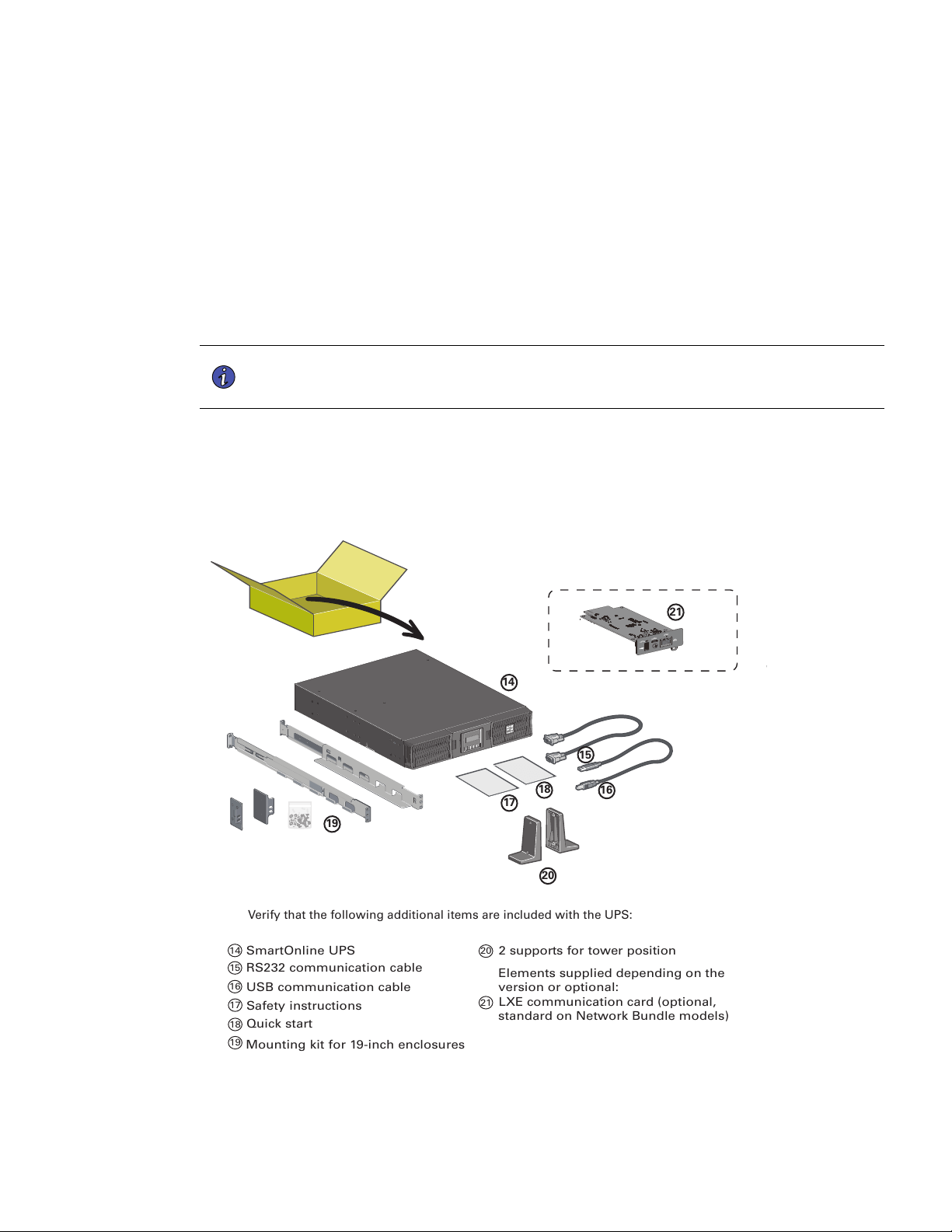
22..22 CChheecckkiinngg tthhee AAcccceessssoorryy KKiitt
• Verify that the following additional items are included with the UPS:
Figure 3. SU750RT / SU1000RT / SU1500RT / SU2200RT / SU3000RT
14
SmartOnline UPS
15
RS232 communication cable
16
USB communication cable
17
Safety instructions
18
Quick start
19
Mounting kit for 19-inch enclosures
20
2 supports for tower position
Elements supplied depending on the
version or optional:
21
LXE communication card (optional,
standard on Network Bundle models)
Verify that the following additional items are included with the UPS:
CONFIG
STATUS
RESET
18
17
20
16
15
14
19
21
8 Tripp Lite by Eaton SmartOnline Series User Guide 614-21325—Rev 01
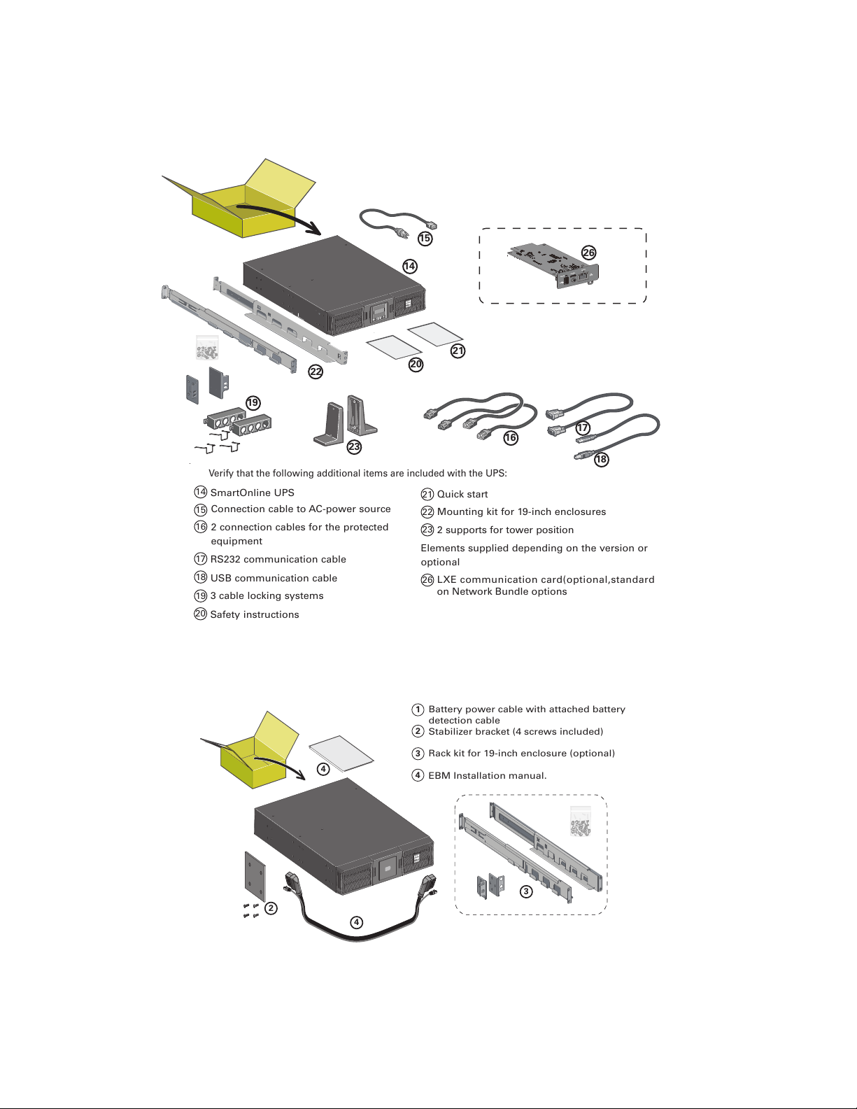
Figure 4. SUINT1000RT / SUINT1500RT / SUINT2200RT / SUINT3000RT
14
21
20
22
23
16
15
19
26
17
18
14
SmartOnline UPS
15
Connection cable to AC-power source
16
2 connection cables for the protected
equipment
17
RS232 communication cable
18
USB communication cable
19
3 cable locking systems
20
Safety instructions
21
Quick start
22
Mounting kit for 19-inch enclosures
23
2 supports for tower position
Elements supplied depending on the version or
optional
26
LXE communication card(optional,standard
on Network Bundle options
Verify that the following additional items are included with the UPS:
CONFIG
STATUS
RESET
Figure 5. BP Accessory Kit
Battery power cable with attached battery
detection cable
Stabilizer bracket (4 screws included)
Rack kit for 19-inch enclosure (optional)
EBM Installation manual.
1
2
3
4
3
4
2
4
Checking the Accessory Kit
Tripp Lite by Eaton SmartOnline Series User Guide 614-21325—Rev 01 9
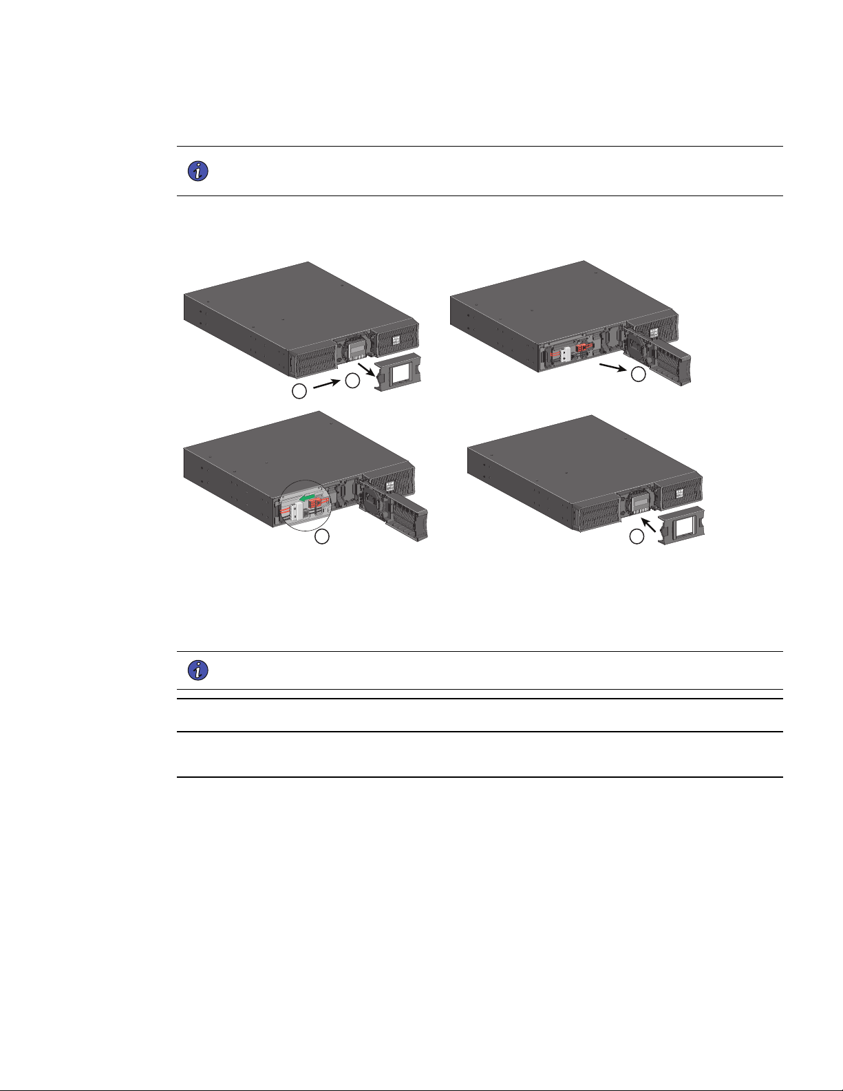
22..33 CCoonnnneeccttiinngg tthhee IInntteerrnnaall BBaatttteerryy
NOTE 1 Place the UPS on a flat, stable surface in its final location.
NOTE 2 Always keep 150 mm of free space behind the UPS rear panel.
Figure 6. Internal Battery Connection
2
1
4
3
5
1. Remove the center cover of the front panel.
2. Push left cover toward to right direction.
3. Open the left side of the front panel.
NOTE A ribbon cable connects the LCD control panel to the UPS. Do not pull on the cable or
disconnect it.
A small amount of arcing may occur when connecting the internal batteries. This is normal and will not harm
personnel. Connect the cables quickly and firmly.
4. Connect the two battery connectors together.
5. Put back the front panel, then clip the center cover.
22..33..11 UUPPSS TToowweerr IInnssttaallllaattiioonn
Tip If you ordered other UPS accessories, refer to specific user manuals to check the tower installation with
the UPS.
To install the cabinet:
1. Place the UPS on a flat, stable surface in its final location.
2. Always keep 6" or 150 mm of free space behind the UPS rear panel for ventilation.
Connecting the Internal Battery
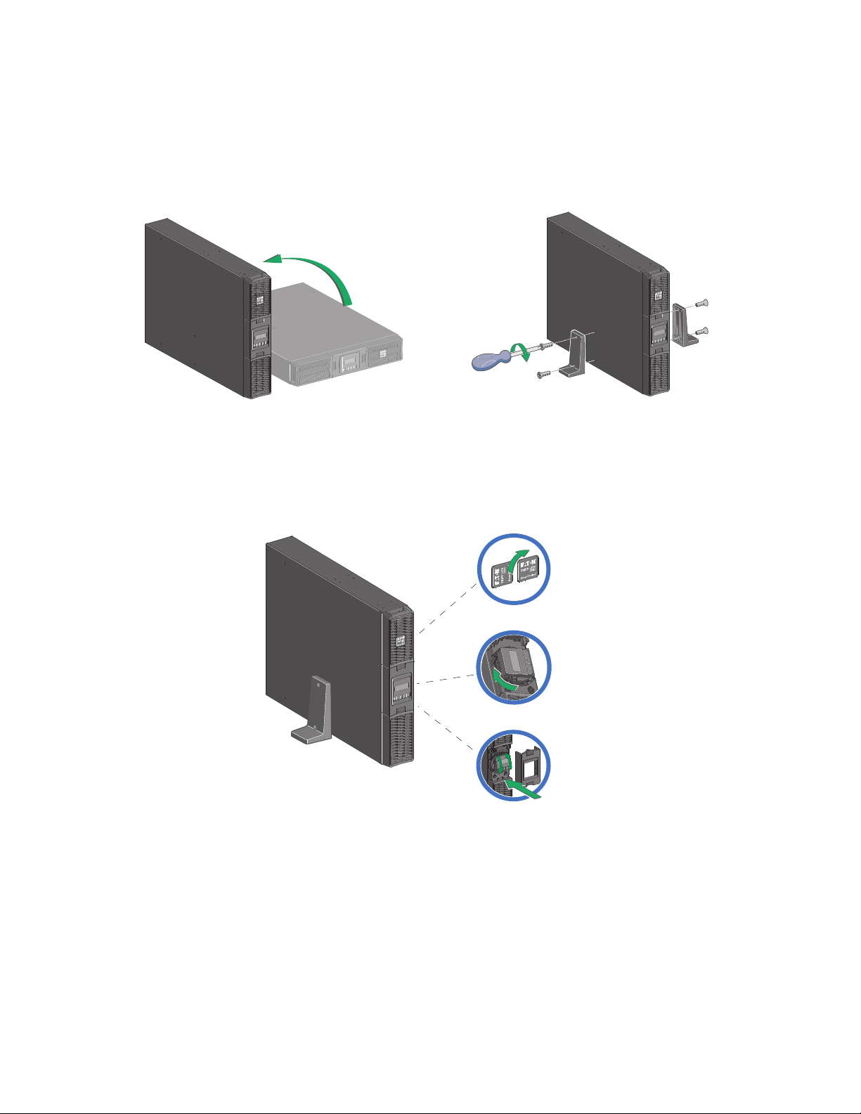
10 Tripp Lite by Eaton SmartOnline Series User Guide 614-21325—Rev 01
3. If installing additional cabinets, place them next to the UPS in their final location.
Figure 7. UPS Tower Install
• Adjustment of the orientation of the LCD panel and of the logo.
Figure 8. Adjusting the LCD
22..33..22 UUPPSS RRaacckk IInnssttaallllaattiioonn
• Rack mounting of UPS, EBM, and accessory modules.
Follow steps 1 to 4 for module mounting on the rails.
Connecting the Internal Battery
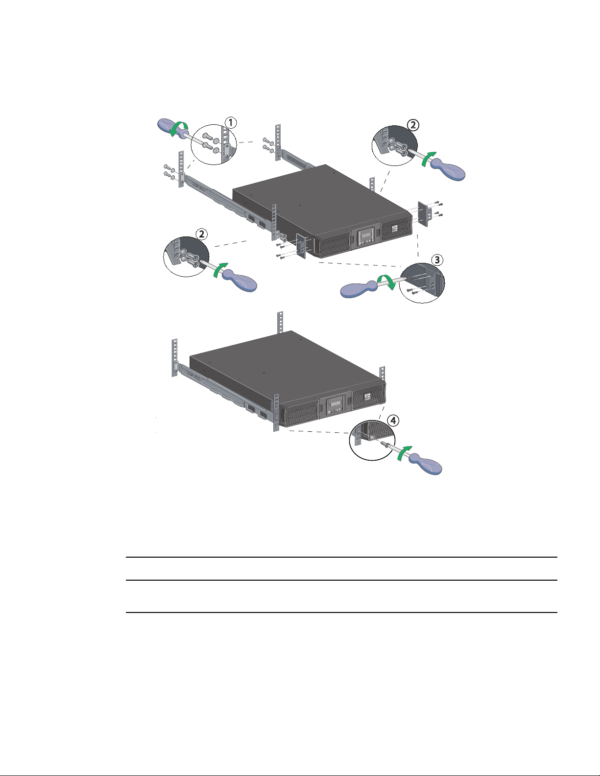
Tripp Lite by Eaton SmartOnline Series User Guide 614-21325—Rev 01 11
Figure 9. Rack Installation
2
1
3
2
4
The rails and necessary hardware are supplied by Eaton.
22..44 SSmmaarrttOOnnlliinnee EExxtteerrnnaall BBaatttteerryy PPaacckk IInnssttaallllaattiioonn
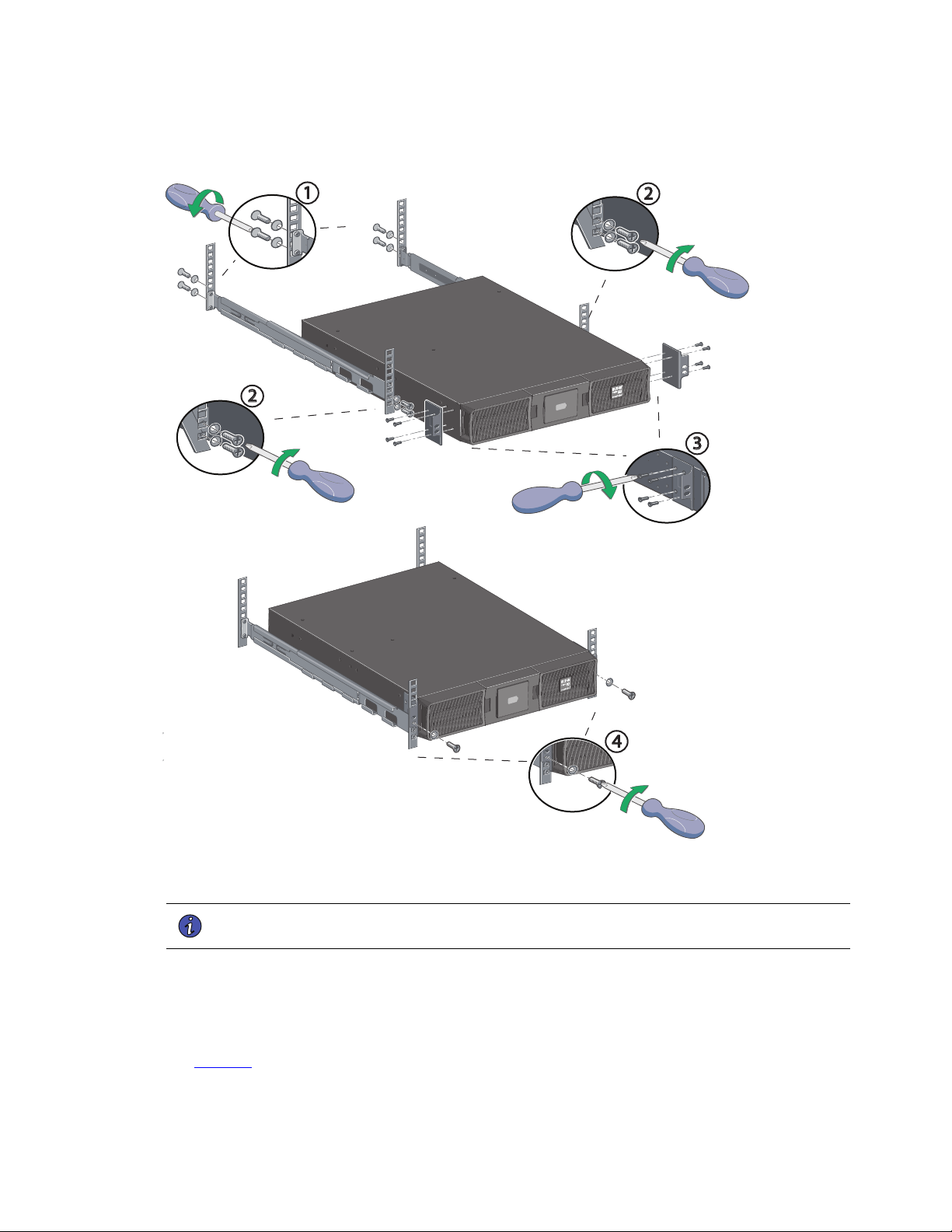
22..44..11 EExxtteerrnnaall BBaatttteerryy RRaacckkmmoouunntt IInnssttaallllaattiioonn
The external battery pack is heavy, wear safety shoes. Handling of the external battery pack will require at least
two people for installation.
To rack mount the external battery pack follow the steps below:
SmartOnline External Battery Pack Installation
12 Tripp Lite by Eaton SmartOnline Series User Guide 614-21325—Rev 01
Figure 10. External Battery Pack Rack Installation
2
1
3
2
4
22..44..22 EExxtteennddeedd BBaatttteerryy PPaacckk RRaacckkmmoouunntt CCoonnnneeccttiioonnss
NOTE A small amount of arcing may occur when connecting an external battery pack to the
UPS. This is normal and will not harm personnel.
To connect the external battery packs to the UPS:
1. Insert the external battery pack cable into the UPS battery connector quickly and firmly.
2. Plug the external battery pack power cable(s) into the external battery connector(s) and repeat until all
external battery packs are connected. Up to 4 external battery packs may be connected to the UPS. See
Figure 11 .
SmartOnline External Battery Pack Installation
Tripp Lite by Eaton SmartOnline Series User Guide 614-21325—Rev 01 13
3. Verify that the external battery pack connections are tight and that adequate bend radius and strain relief
exist for each cable.
4. Connect the battery detection cable(s) to the connector of the UPS and of the external battery pack(s).
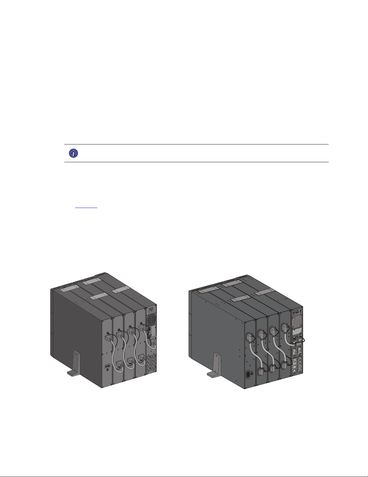
Figure 11. Rackmount External Battery Pack Connections
BP36RT / BP48RT BP72RT
22..44..33 UUPPSS aanndd EExxtteennddeedd BBaatttteerryy PPaacckk TToowweerr IInnssttaallllaattiioonn
Tip If you ordered other UPS accessories, refer to specific user manuals to check the tower installation with
the UPS.
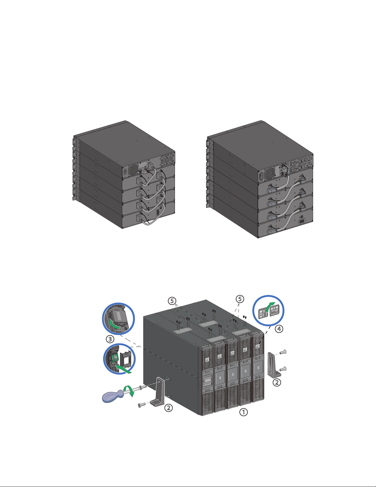
Figure 12. UPS and Extended Battery Pack Tower Installation
2
2
3
4
1
5
5
SmartOnline External Battery Pack Installation
14 Tripp Lite by Eaton SmartOnline Series User Guide 614-21325—Rev 01
To install the cabinets:
1. Place the UPS and external battery pack(s) on a flat, stable surface in their final location in the tower
orientation. If installing additional external battery cabinets, place them next to the UPS.
2. Attach the mounting feet and stabilizer brackets.
3. Adjust the LCD on the UPS.
4. Rotate the logo on the UPS and external battery packs into the correct orientation.
5. Attach the extended battery pack stabilizer brackets to each cabinet.
6. Always keep 6" or 150 mm of free space behind the UPS rear panel for ventilation.
22..44..44 EExxtteennddeedd BBaatttteerryy PPaacckk TToowweerr CCoonnnneeccttiioonnss
NOTE A small amount of arcing may occur when connecting an external battery pack to the
UPS. This is normal and will not harm personnel.
To connect the external battery packs to the UPS:
1. Insert the external battery pack cable into the UPS battery connector quickly and firmly.
2. Plug the external battery pack power cable(s) into the external battery connector(s) and repeat until all
external battery packs are connected. Up to 4 external battery packs may be connected to the UPS. See
Figure 13 .
3. Verify that the external battery pack connections are tight and that adequate bend radius and strain relief
exist for each cable.
4. Connect the battery detection cable(s) to the connector of the UPS and of the external battery pack(s).
Figure 13. Tower Mount External Battery Pack Connections
BP36RT / BP48RT BP72RT
SmartOnline External Battery Pack Installation
Tripp Lite by Eaton SmartOnline Series User Guide 614-21325—Rev 01 15
CChhaapptteerr 33 IInntteerrffaacceess aanndd CCoommmmuunniiccaattiioonn
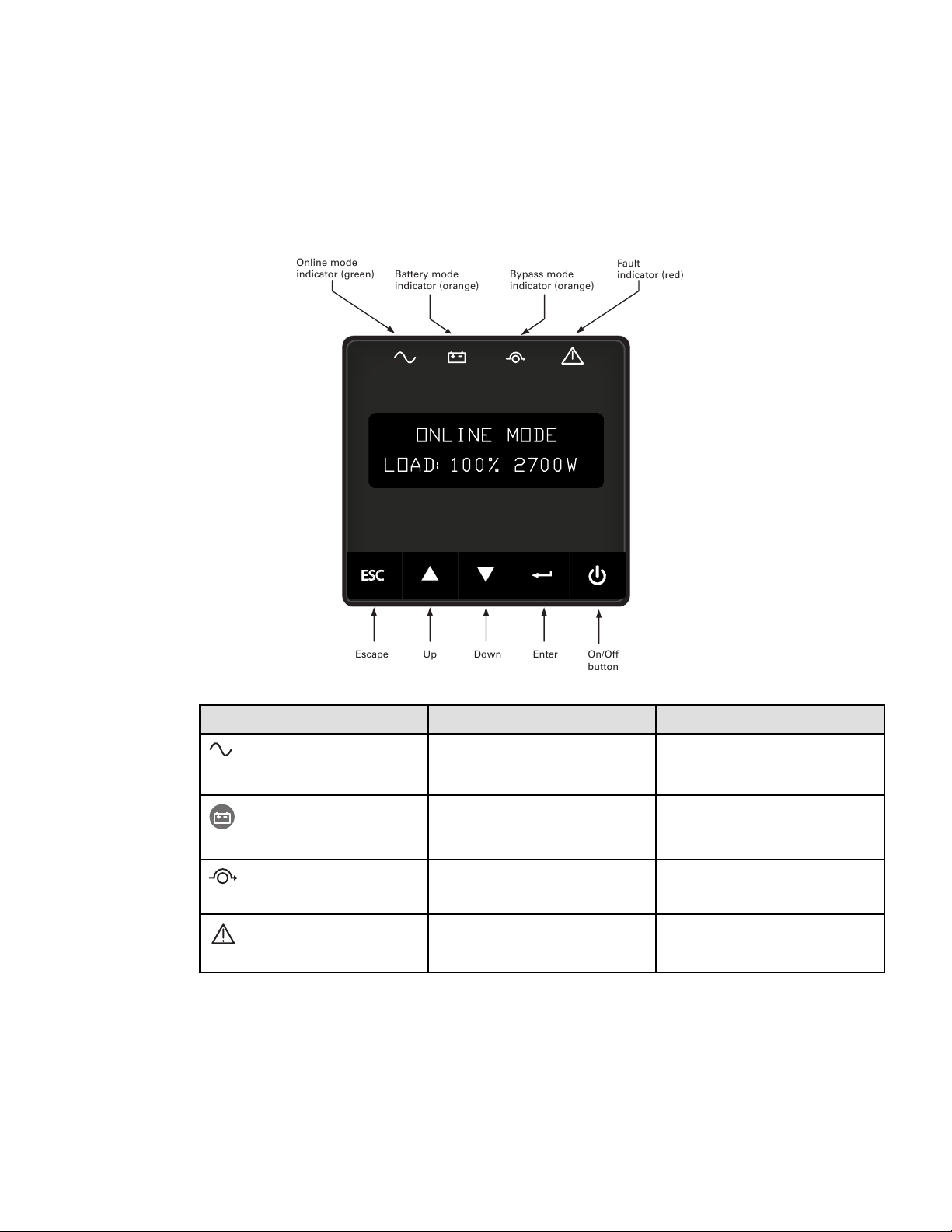
33..11 CCoonnttrrooll PPaanneell
Figure 14. Control Panel
Online mode
indicator (green)
Fault
indicator (red)
Escape Up Down Enter On/Off
button
Battery mode
indicator (orange)
Bypass mode
indicator (orange)
ONLINE MODE
LOAD:100% 2700W
ESC
Indicator Status Description
Green
On
The UPS is operating normally on Online,
on High Efficiency mode or on battery
mode.
Orange
On The UPS is on Battery mode.
Orange
On The UPS is on Bypass mode.
Red
On
The UPS has an active alarm or fault.
16 Tripp Lite by Eaton SmartOnline Series User Guide 614-21325—Rev 01
33..22 LLCCDD DDeessccrriippttiioonn
The LCD screen has 2 lines, each line has 16 characters. The first line shows UPS status, the second line
shows measures.
After 5 minutes of inactivity, the LCD displays the screen saver, and the LCD backlight automatically dims.
Press any button to restore the screen.
Note: If fault or alarm appears, the first line of LCD will cycle between fault/alarm message and UPS mode, see
troubleshooting page for additional information.
Figure 15. LCD Description
LCD mode description
Load/equipment status
ONLINE MODE
LOAD:100% 2700W
ESC
The following table describes the status information provided by the UPS
Note: If other indicator appears, see the troubleshooting for additional information.
Table 4. LCD Operating Modes
UPS Display Description
STANDBY MODE
IN:120V 60.0HZ
Equipment is not powered until button is pressed. The UPS
is Off, waiting for startup command from user.
LOAD:100% 3000VA
ONLINE MODE
The UPS is powering and protecting the equipment. The UPS is
operating normally.
RUNTIME:104MIN
BATTERY MODE
A utility failure has occurred and the UPS is on Battery mode.
The UPS is powering the equipment with the battery power.
Prepare your equipment for shutdown.
LCD Description
Tripp Lite by Eaton SmartOnline Series User Guide 614-21325—Rev 01 17
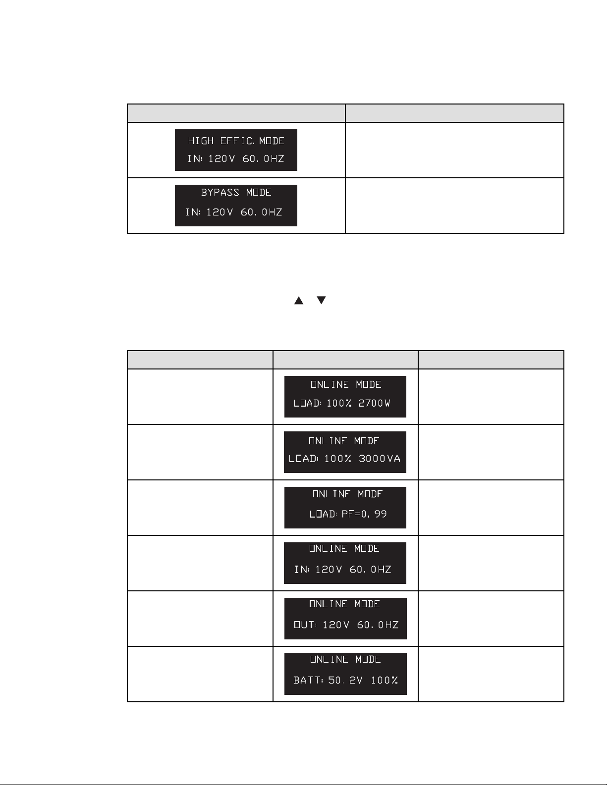
Table 4. LCD Operating Modes (Continued)
UPS Display Description
IN:120V 60.0HZ
HIGH EFFIC.MODE
The UPS is operating on High Efficiency mode. The UPS is
powering and protecting the equipment
IN:120V 60.0HZ
BYPASS MODE
An overload or a fault has occurred, or a command has been
received, and the UPS is in Bypass mode. Equipment is powered
but not protected by the UPS.
33..33 UUPPSS HHoommee MMeennuu
The SmartOnline UPS will display the Home Menu by default. The Home Menu will display the UPS mode and
contains nine different types of UPS measurements that can be seen by navigating the menu.
Navigate the Home Menu by pressing the
or buttons on the display.
Press the ESC button to return to the first measurement of the Home Menu.
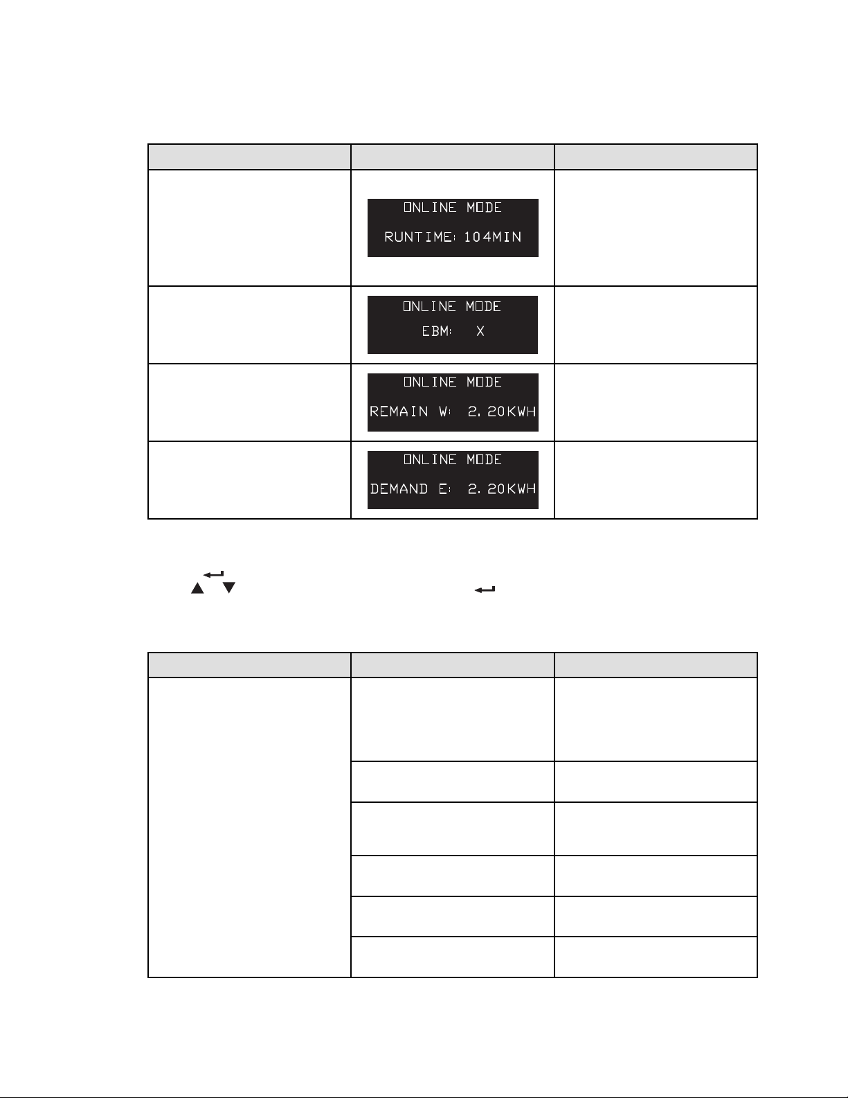
Table 5. UPS Home Menu
Display Information LCD Display
Bottom Row Values
Displays the UPS mode , load percentage
and W.
LOAD:100% 2700W
ONLINE MODE
The LOAD data screen specifies the
amount of power that connected
equipment is currently using in terms of
percentage and Watt.
Displays the UPS mode , load percentage
and VA.
LOAD:100% 3000VA
ONLINE MODE
The OUTPUT LOAD LEVEL screen
indicates the load percentage and VA
output load level.
Displays the UPS mode and output load
power factor.
LOAD:PF=0.99
ONLINE MODE
The OUTPUT LOAD POWER FACTOR
screen indicates the power factor of
connected equipment.
Displays the UPS mode , input voltage
and frequency.
IN:120V 60.0HZ
ONLINE MODE
The INPUT VOLTAGE & FREQUENCY
screen displays current UPS input data.
Displays the UPS mode and output
voltage and frequency.
OUT:120V 60.0HZ
ONLINE MODE
The OUTPUT VOLTAGE & FREQUENCY
screen displays current UPS output data.
Displays the UPS mode , battery voltage
and battery charge percentage.
BATT:50.2V 100%
ONLINE MODE
The BATTERY voltage screen tracks the
charge level of your connected battery
bank in terms of voltage and charge
percentage.
UPS Home Menu
18 Tripp Lite by Eaton SmartOnline Series User Guide 614-21325—Rev 01
Table 5. UPS Home Menu (Continued)
Display Information LCD Display
Bottom Row Values
Displays the UPS mode , and remaining
battery runtime.
RUNTIME:104MIN
ONLINE MODE
The RUNTIME remaining screen tracks
the approximate minutes of runtime
available under the current loading and
battery pack configuration. The runtime
value will automatically re-calculate as
connected equipment power consumption
changes.
Displays the UPS mode , and external
battery quantity.
EBM: X
ONLINE MODE
The EBM screen display external battery
quantity.
Displays the UPS mode , and remaining
Watts of UPS.
REMAIN W: 2.20KWH
ONLINE MODE
The REMAIN WATTS screen tracks the
remaining capacity of the UPS in
kilowatt.
Displays the UPS mode and cumulative
demand energy by the UPS.
DEMAND E: 2.20KWH
ONLINE MODE
The DEMAND ENERGY screen offers
continuous data on the KWh (kilowatt-
hour) that connected equipment has
consumed in the last one-hour period.
33..44 DDiissppllaayy FFuunnccttiioonnss
Press the button from the UPS Home Menu to activate the additional menu options. Use the two middle
buttons
or to scroll thru the menu structure. Press the button to validate the selected item. Pressing
the ESC button will exit to the previous menu level / screen.
Table 6. Display Functions
Main Menu Submenu
Display Information or Menu function
CONTROL
GO TO BYPASS / GO BACK NORMAL
GO TO BYPASS command is used to force
ups to bypass mode from ONLINE MODE.
GO BACK NORMAL command is used to
comeback to line mode from BYPASS
MODE.
BATTERY TEST
BATTERY TEST command is used to start
battery test.
RESET FAULT ST
RESET FAULT ST command is used to
reset all faults. But some faults may not
be cleared.
CLEAR EVENT LOG
CLEAR EVENT LOG command is used to
clear all the event log.
RESET KWH USED
RESET KWH USED is used to reset the
power used.
FACTORY SETT
FACTORY SETT command is used to
restore factory settings.
Display Functions

Tripp Lite by Eaton SmartOnline Series User Guide 614-21325—Rev 01 19
Table 6. Display Functions (Continued)
Main Menu Submenu
Display Information or Menu function
LOCAL SETTINGS
LANGUAGE
User can select language from this
submenu.
AUDIBLE ALARM
Audible alarm can be set through this
menu.
IN/OUT SETTINGS
OUTPUT VOLTAGE
Select output voltage through this menu.
OUTPUT FREQUENCY
Select output frequency through this
menu.
HIGH EFFIC. MODE
Select high efficiency mode enabled or
disabled through this menu.
OVRLOAD PREALARM
Overload pre-alarm can be set through
this menu.
ON/OFF SETTINGS
COLD START
Cold start can be enabled or disabled
through this menu.
AUTO RESTART
Auto restart can be enabled or disabled
through this menu.
AUTO START
Auto start can be enabled or disabled
through this menu.
START ON BYPASS
Start on bypass can be enabled or
disabled through this menu.
SLEEP MODE
Sleep mode can be enabled or disabled
through this menu.
SITE WIRING FLT
Site wiring fault can be enabled or
disabled through this menu.
BATTERY SETTINGS
AUTO BAT TEST
Auto battery test period can be set
through this menu.
RESTART LEVEL
Restart battery level can be set through
this menu.
BAT LOW LEVEL
Battery low percentage can be set
through this menu.
BAT LOW TIME
Battery low remaining time can be set
through this menu.
COM SETTINGS
REMOTE ON/OFF
Select input signal function for REMOTE
ON/OFF.
REMOTE PWR OFF
Select input signal function for REMOTE
PWR OFF.
INPUT DB9-4
Select input signal function for INPUT
DB9-4.
OUTPUT RELAY
Select output signal function for OUTPUT
RELAY.
OUTPUT DB9-1
Select output signal function for OUTPUT
DB9-1.
Display Functions
20 Tripp Lite by Eaton SmartOnline Series User Guide 614-21325—Rev 01
Table 6. Display Functions (Continued)
Main Menu Submenu
Display Information or Menu function
OUTPUT DB9-7
Select output signal function for OUTPUT
DB9-7.
OUTPUT DB9-8
Select output signal function for OUTPUT
DB9-8.
EVENT LOG
Event log has 50 items to show what
happened.
IDENTIFICATION
This menu shows IDENTIFICATION
information.
33..55 UUsseerr SSeettttiinnggss
The following table displays the options that can be changed by the user. From the UPS Home Menu press the
button. This will open the Main Menu Screen . To select a menu option use the or buttons. Press the
button to validate the selected item. Pressing the ESC button will exit to the previous menu level / screen.
Table 7. User Settings
Main Menu Screen Submenu Submenu Menu Function
CONTROL
GO TO BYPASS / GO BACK
NORMAL
GO TO BYPASS / GO BACK
NORMAL?
GO TO BYPASS command is
used to force ups to bypass
mode from ONLINE MODE.
GO BACK NORMAL command
is used to comeback to line
mode from BYPASS MODE.
BATTERY TEST BATTERY TEST? BATTERY TEST command is
used to start battery test.
RESET FAULT ST RESET FAULT ST? RESET FAULT ST command is
used to reset all faults. But
some faults may not be
cleared.
CLEAR EVENT LOG CLEAR EVENT LOG? CLEAR EVENT LOG command
is used to clear all the event
log.
RESET KWH USED RESET KWH USED? RESET KWH USED is used to
reset the power used.
FACTORY SETT FACTORY SETT? FACTORY SETT command is
used to restore factory
settings.
LOCAL SETTINGS
LANGUAGE ENGLISH* (Default)
[FRANCAIS] [ESPANOL]
Sets displayed language for
Menus, status and alarms.
UPS fault, Event log data and
settings are in all supported
languages.
AUDIBLE ALARM
ENABLED* (Default)
[ENABLED] [DISABLED ON
BAT] [ALWAYS DISABLED]
Enables or disables the
audible alarm.
User Settings

Tripp Lite by Eaton SmartOnline Series User Guide 614-21325—Rev 01 21
Table 7. User Settings (Continued)
Main Menu Screen Submenu Submenu Menu Function
IN / OUT SETTINGS
OUTPUT VOLTAGE 120V* (LV Default) [100V]
[110V] [120V] [125V]
208V* (HV Default) [200V]
[208V] [220V] [230V] [240V]
Sets the UPS output voltage,
UPS must be in standby to
choose output voltage setting.
OUTPUT FREQUENCY AUTOSENSING* (Default)
[AUTO SENSING] [FREQ
CONV. 50HZ] [FREQ CONV.
60HZ]
Sets the output frequency,
output frequency follows the
input frequency,
HIGH EFFIC. MODE DISABLED* (Default)
[ENABLED] [DISABLED]
Power the output from bypass
for high efficiency
OVERLOAD PREALARM 102%* (Default) [50%]
[55%]....[100%][102%]
Load % when overload alarm
occurs
ON / OFF SETTINGS
COLD START ENABLED* (Default)
[ENABLED] [DISABLED]
Allows the SmartOnline UPS
to start on battery power.
AUTO RESTART ENABLED* (Default)
[ENABLED] [DISABLED]
Allows the SmartOnline UPS
to restart automatically when
mains recovers after a
complete battery discharge.
AUTO START ENABLED* (Default)
[ENABLED] [DISABLED]
The SmartOnline UPS starts
up as soon as mains power is
available.
START ON BYPASS ENABLED* (Default)
[ENABLED] [DISABLED]
Allows the SmartOnline UPS
to start in bypass mode.
SLEEP MODE ENABLED* (Default)
[ENABLED] [DISABLED]
If Disabled, LCD and
communication will turn off
immediately afterSmartOnline
UPS is OFF. If Enabled, LCD
and communication stays ON
1h30 min after the
SmartOnline UPS is OFF.
SITE WIRING FLT ENABLED* (Default)
[ENABLED] [DISABLED]
Prevents the SmartOnline UPS
from starting in case of phase
to neutral wire swapping or
improper grounding,
BATTERY SETTINGS
AUTO BAT TEST MONTHLY*(Default) [NO
TEST] [DAILY] [WEEKLY]
[MONTHLY]
Allows the SmartOnline UPS
to perform an automatic
battery test.
RESTART LEVEL 0%* (Default) [0%]....[100%] Allows the SmartOnline UPS
to restart when the set
percentage battery charge is
reached.
BATT LOW LEVEL 0%* (Default) [0%]....[100%]
The alarm triggers when the
set percentage of battery
charge is reached.
User Settings

22 Tripp Lite by Eaton SmartOnline Series User Guide 614-21325—Rev 01
Table 7. User Settings (Continued)
Main Menu Screen Submenu Submenu Menu Function
BATT LOW TIME 3 MIN* (Default) [0MIN]
[3MIN] .. [60MIN]
The alarm triggers when the
set battery time remaining is
reached.
COM SETTINGS
REMOTE ON /OFF NO* (Default) [NO] [ROO]
[RPO] [BUILDING ALARM]
[FORCED BYPASS] [ON
GENERATOR] [SHUTDOWN
CMD]
Delay time and active cannot
set by LCD.
delay time: 3s
active: open
Sets events or fault that will
actuate Output signal
parameters through external
contact connector.
REMOTE PWR OFF NO* (Default) [NO] [ROO]
[RPO] [BUILDING ALARM]
[FORCED BYPASS] [ON
GENERATOR] [SHUTDOWN
CMD]
Delay time and active cannot
set by LCD.
delay time: 3s
active: open
Sets events or fault that will
actuate Output signal
parameters through external
contact connector.
INPUT DB9–4
NO* (Default) [NO] [ROO]
[RPO] [BUILDING ALARM]
[FORCED BYPASS] [ON
GENERATOR] [SHUTDOWN
CMD]
Delay time and active cannot
set by LCD.
delay time: 3s
active: open
Sets events or fault that will
actuate Output signal
parameters through external
contact connector or RS232.
OUTPUT RELAY BATTERY FAULT* (Default)
[ON BATTERY] [LOW
BATTERY] [BATTERY FAULT]
[BYPASS] [UPS OK] [LOAD
PROTECTED] [LOAD
POWERED] [GENERAL
ALARM] [BAT CHARGING]
[OVLD PREALARM] [BAT
DISCONN]
Sets events or fault that will
actuate Output signal
parameters through external
contact connector or RS232.
OUTPUT DB9–1 LOW BATTERY* (Default) [ON
BATTERY] [LOW BATTERY]
[BATTERY FAULT] [BYPASS]
[UPS OK] [LOAD PROTECTED]
[LOAD POWERED] [GENERAL
ALARM] [BAT CHARGING]
[OVLD PREALARM] [BAT
DISCONN]
Sets events or fault that will
actuate Output signal
parameters through external
contact connector or RS232.
User Settings
Tripp Lite by Eaton SmartOnline Series User Guide 614-21325—Rev 01 23
Table 7. User Settings (Continued)
Main Menu Screen Submenu Submenu Menu Function
OUTPUT DB9–7 UPS OK* (Default) [ON
BATTERY] [LOW BATTERY]
[BATTERY FAULT] [BYPASS]
[UPS OK] [LOAD PROTECTED]
[LOAD POWERED] [GENERAL
ALARM] [BAT CHARGING]
[OVLD PREALARM] [BAT
DISCONN]
Sets events or fault that will
actuate Output signal
parameters through external
contact connector or RS232.
OUTPUT DB9–8 ON BATTERY* ( Default) [ON
BATTERY] [LOW BATTERY]
[BATTERY FAULT] [BYPASS]
[UPS OK] [LOAD PROTECTED]
[LOAD POWERED] [GENERAL
ALARM] [BAT CHARGING]
[OVLD PREALARM] [BAT
DISCONN]
Sets events or fault that will
actuate Output signal
parameters through external
contact connector or RS232.
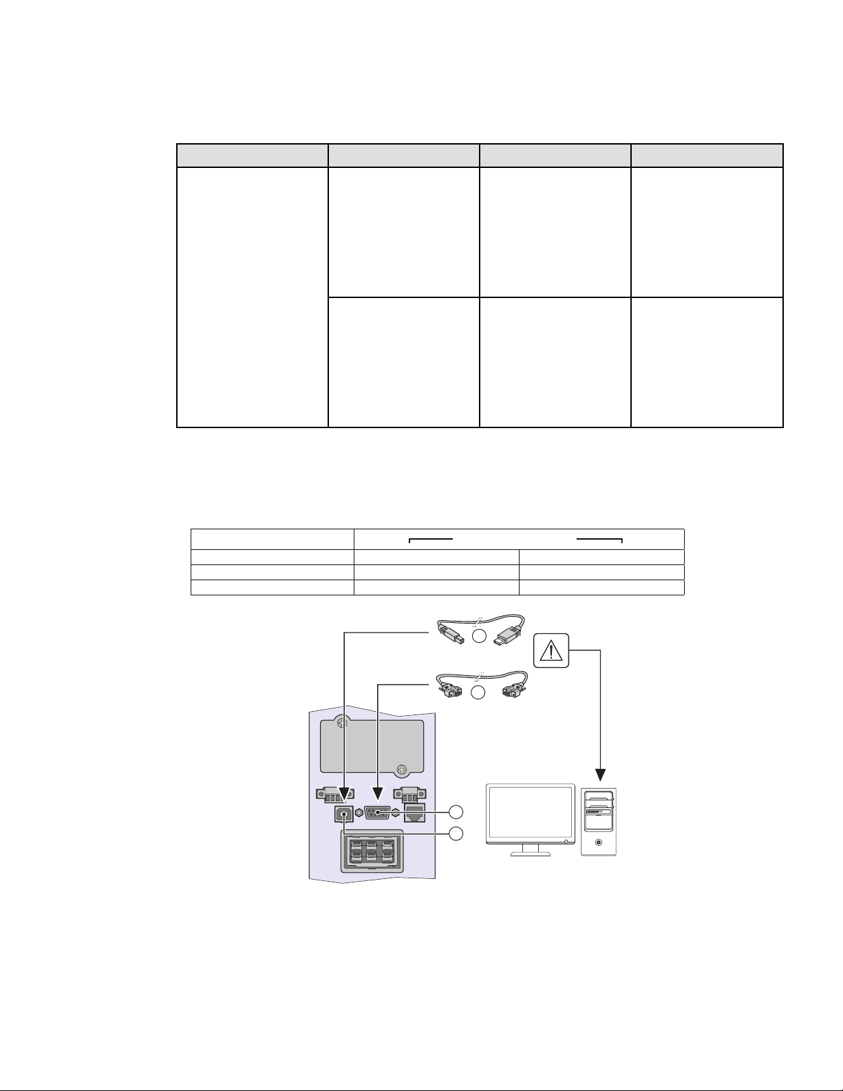
33..66 CCoommmmuunniiccaattiioonn PPoorrttss
CCoonnnneeccttiinngg ttoo tthhee RRSS223322 oorr UUSSBB CCoommmmuunniiccaattiioonn PPoorrtt
9
10
17
18
Independent
Communication Bay USB RS-232
Any connectivity card Available
Any connectivity card Available
Available
Available
USB and RS232 are Independant
1. Connect the RS232 ⑰ or USB ⑱ communication cable to the serial or USB port on the computer
equipment.
Communication Ports
24 Tripp Lite by Eaton SmartOnline Series User Guide 614-21325—Rev 01
2. Connect the other end of the communication cable ⑰ or ⑱ to the USB ⑩ or the RS232 ⑨ communication
port on the UPS.
The UPS can now communicate with Tripp Lite by Eaton PowerAlert management software.
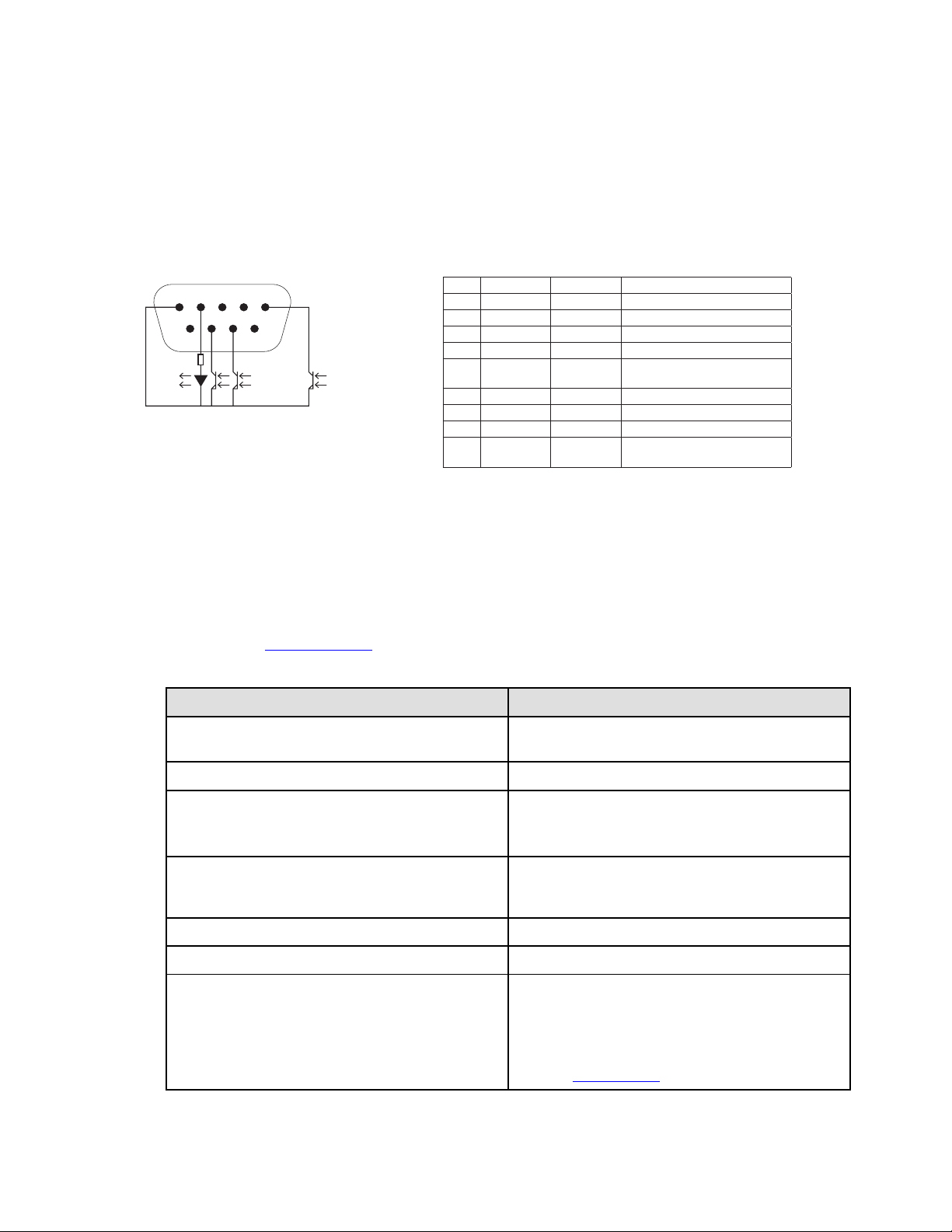
CChhaarraacctteerriissttiiccss ooff tthhee ccoonnttaacctt RRSS223322 CCoommmmuunniiccaattiioonn PPoorrtt
1
6789
300 Ohm
R
2345
Pin Signal Direction Function
1 Bat Low Output Low Battery Output
2 TxD Output Transmit to external device
3 RxD Input Receive from external device
4 I/P SIG Input -
5 GNDS - Signal Common tied to
chassis
6 PNP Input Plug and Play
7 UPS ON Output UPS ON
8 BAT Mode Output -
9 +5V Output Power supply for external
signals or options
Contact characteristics (optocoupler)
• Voltage: 48 V DC max
• Current: 25 mA max
33..77 RReemmoottee CCoonnttrrooll FFuunnccttiioonnss
Programmable Signal Inputs
The Tripp Lite by Eaton SmartOnlineUPS incorporates 3 programmable signal inputs: one Remote Power Off
(RPO) input terminal, one Remote On/Off (ROO) input terminal, one RS-232 input (pin-4). Signal inputs can be
configured see (3.5 User Settings) Settings > Com settings > Signal Input in to have one of the following
functions:
Function Description
No No function, please choose a function if you want to use input
signal
RPO Remote Power Off (RPO) is used to shutdown the UPS remotely
ROO
Remote On/Off allows remote action of button to switch On/Off
the UPS.
(Cold start is prohibited while using the ROO function)
Forced bypass
If feeding the load the unit goes to bypass operation and stays
there regardless of the bypass state until the input is
inactivated
Building alarm Active input generates an alarm “building alarm”
On generator Active input disables synchronization and transfers to bypass
Remote shutdown
Active input turns UPS output (or outlet groups) off after a user
defined shutdown delay but keeps on charging batteries
according to a selected charging scheme, inactive input does
not abort shutdown countdown. Depending on the “Restart”
parameter the unit may startup automatically. See ON /OFF
settings in 3.5 User Settings .
Remote Control Functions
Tripp Lite by Eaton SmartOnline Series User Guide 614-21325—Rev 01 25
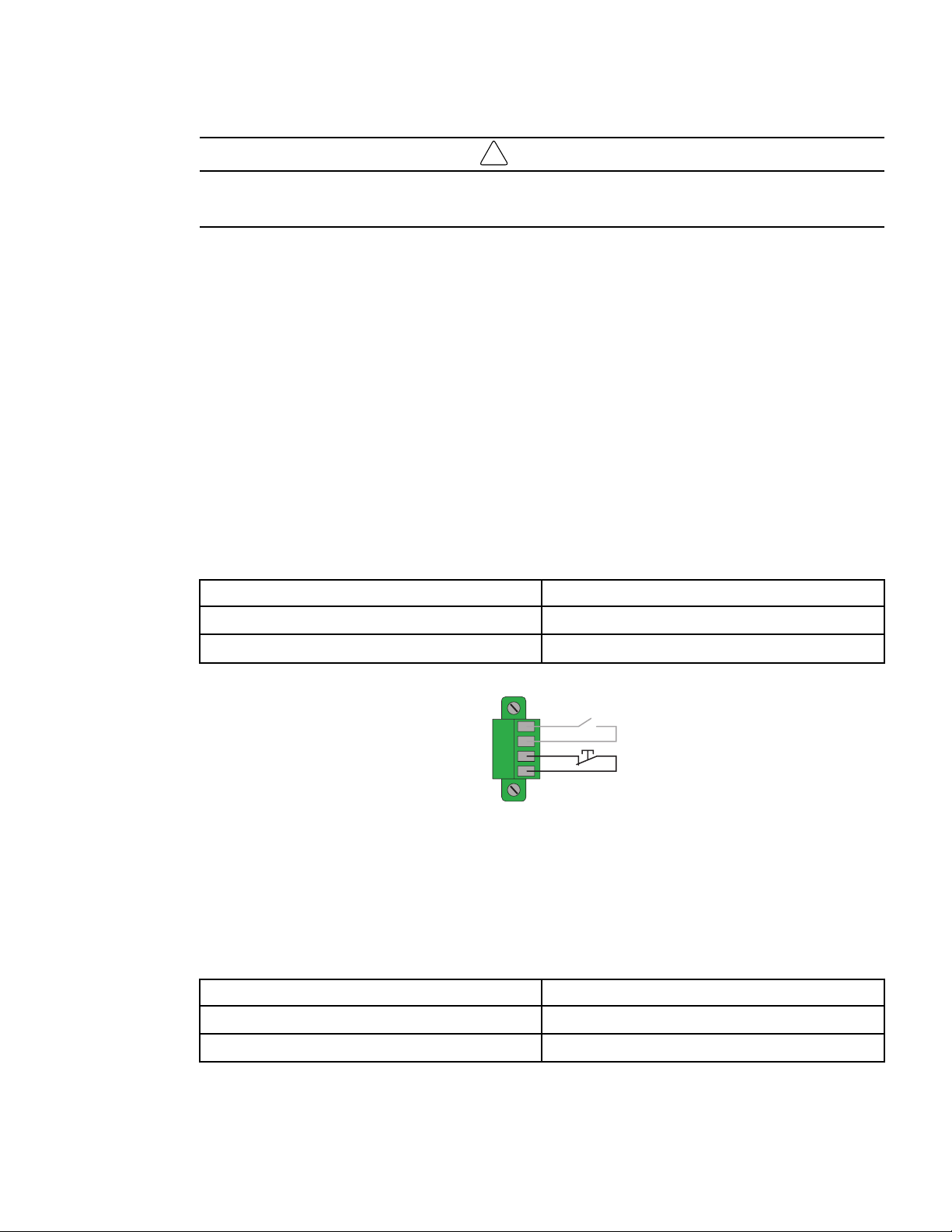
!
IMPORTANT
Warning Signal inputs have no function by default. Please choose a function through the LCD (COM SETTING-
>REMOTE ON/OFF, REMOTE PWR OFF, INPUT DB9-4).
See below 2 examples of configuration with RPO terminal used as RPO function and ROO terminal use as
ROO function:
Remote Power Off (RPO)
RPO is used to shutdown the UPS remotely when the contact is open. This feature can be used for shutting
down the load and the UPS by thermal relay, for instance in the event of room over temperature. When RPO is
activated, the UPS shuts down the output and all its power converters immediately. The UPS remains on to
alarm the fault. The RPO circuit is an IEC 60950 safety extra low voltage (SELV) circuit. This circuit must be
separated from any hazardous voltage circuits by reinforced insulation.
• The RPO must not be connected to any utility connected circuits. Reinforced insulation to the utility is
required. The RPO switch must be a dedicated latching-type switch not tied into any other circuit. The RPO
signal must remain active for at least 250 ms for proper operation.
• To ensure the UPS stops supplying power to the load during any mode of operation, the input power must
be disconnected from the UPS when the Remote Power Off function is activated.
Leave the RPO connector installed in the RPO port on the UPS even if the RPO function is not needed.
RPO connections:
RPO Comments
Connector type Terminal, 14 AWG maximum wires
External breaker specification 60 V DC/30V AC 20mA max
RPO
ROO
Remote On/Off (ROO)
• Remote On/Off allows remote action of button to switch On/Off the UPS.
• When contact changes from open to closed, the UPS is switched-on (or stays On).
• When contact changes from closed to open, the UPS is switched-off (or stays Off).
• On/Off control via button has priority over the remote control.
RPO Comments
Connector type Terminal, 14 AWG maximum wires
External breaker specification 60 V DC/30V AC 20mA max
Remote Control Functions
26 Tripp Lite by Eaton SmartOnline Series User Guide 614-21325—Rev 01
RPO
ROO
Remote Control Connection and Test
1. Check the UPS is shut down and the electrical supply network disconnected.
2. Remove RPO connector from the UPS by unfitting the screws.
3. Connect a normally closed volt-free contact between the two pins of connector.
RPO
Normally Closed
Contact open: shut down of UPS
To return to normal operation, deactivate the external remote
shut down
contact and restart the UPS from the front panel.
4. Plug the RPO connector into the back of the UPS and fix the screws.
5. Connect and restart the UPS according to the previously described procedures.
6. Activate the external remote shut down contact to test the function. Always test the RPO function before
applying your critical load to avoid accidental load loss.
Programmable Signal Outputs
The Tripp Lite by Eaton SmartOnlineUPS incorporates 4 programmable signal outputs: one relay output, three
optocouplers outputs (pin- 1/7/8). Signal outputs can be configured (see COM SETTING->OUTPUT RELAY,
OUTPUT DB9-1,OUTPUT DB9-7,OUTPUT DB9-8 to report the following information:
Signal Default Assignment Description
On battery (On bat)
DB9-Pin 8 UPS is in battery mode
Low battery (Low bat)
DB9-Pin 1 Battery is nearly empty
Battery fault (Bat fault)
-
Battery fault
Bypass
Relay output (1)
UPS is operating in Bypass mode
UPS OK
DB9-Pin 7
Load is powered (from inverter or bypass), with
no alarm
Load powered
-
Load is powered (from inverter or bypass)
Load protected
-
UPS is on inverter, with no alarm and ready to go
to battery
General alarm
-
Choose events that will trigger this alarm trough
the LCD
Remote Control Functions
Tripp Lite by Eaton SmartOnline Series User Guide 614-21325—Rev 01 27
Signal Default Assignment Description
BAT CHARGING
-
Control an optional external battery charger on
and off.
OVL pre-alarm
-
Overload pre-alarm
(1) Relay output:
Normally Closed
Normally Open
Common
1
2
3
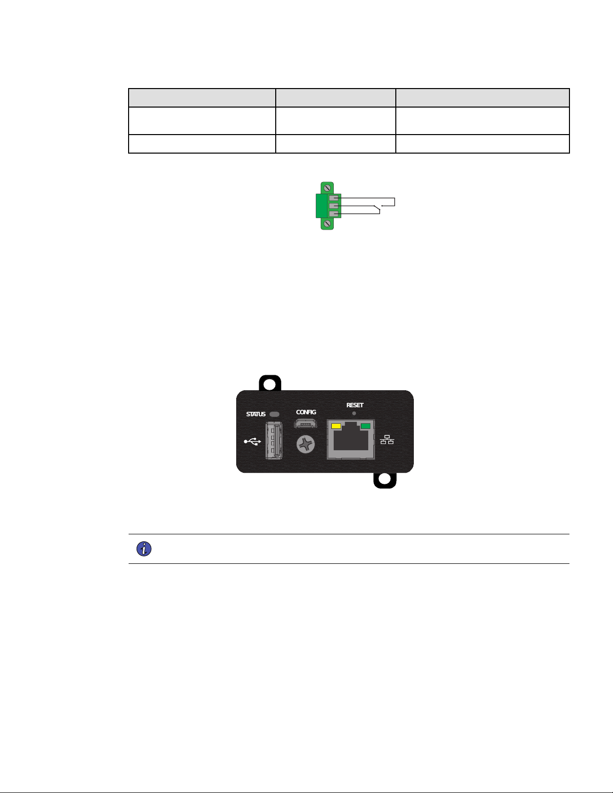
Connectivity Cards
Connectivity cards allow the UPS to communicate in a variety of networking environments and with different
types of devices. The Tripp Lite by Eaton SmartOnlineUPS models have one available communication bay for
the following connectivity cards:
• Network card (WEBCARDLXE) — Provides monitoring and control using an SNMP network management
platform, web browser, SSH or Telnet.
Figure 16. WEBCARDLXE Connectivity Card
CONFIG
STATUS
RESET
IInnssttaallllaattiioonn ooff tthhee ccoommmmuunniiccaattiioonn ccaarrdd ((ooppttiioonnaall))
NOTE Connect a Cat-6 shielded ethernet cable (F/UTP or F/FTP) or higher between the LX
Platform device’s ethernet port and a network jack.
It is not necessary to shutdown the UPS before installing a communication card.
Remote Control Functions
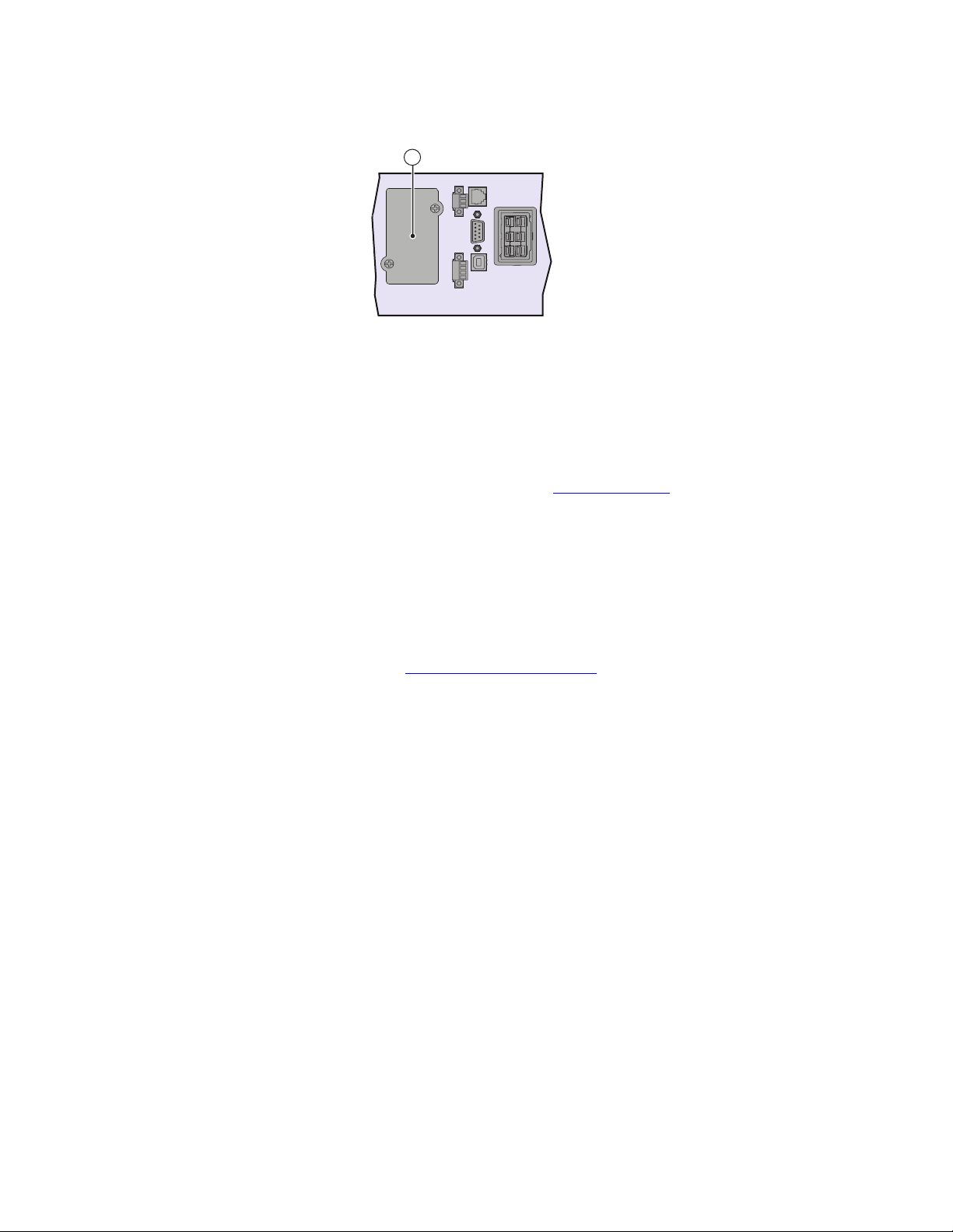
28 Tripp Lite by Eaton SmartOnline Series User Guide 614-21325—Rev 01
2
1. Remove the slot cover ② secured by screws.
2. Inset the communication card in the slot.
3. Secure the card with the 2 screws.
33..88 TTrriipppp LLiittee BByy EEaattoonn PPoowweerrAAlleerrtt SSooffttwwaarree SSuuiittee
Tripp Lite by Eaton PowerAlert software suite is available from www.tripplite.com . The PowerAlert software
suite provides up-to-date graphics of UPS power and system data and power flow. It also gives you a complete
record of critical power events, and it notifies you of important UPS or power information. If there is a power
outage and the SmartOnline UPS battery power becomes low, the PowerAlert Software suite can
automatically shut down your computer system to protect your data before the UPS shutdown occurs.
33..99 CCyybbeerrsseeccuurriittyy
Tripp Lite by Eaton is committed to minimizing the Cybersecurity risk in its products and deploys cybersecurity
best practices and latest cybersecurity technologies in its products and solutions, making them more secure,
reliable and competitive for our customers. Tripp Lite by Eaton also offers Cybersecurity Best Practices white
papers to its customers, referenced at www.eaton.com/cybersecurity.
Tripp Lite By Eaton PowerAlert Software Suite

Tripp Lite by Eaton SmartOnline Series User Guide 614-21325—Rev 01 29
CChhaapptteerr 44 OOppeerraattiioonn
44..11 SSttaarrtt--uupp aanndd NNoorrmmaall ooppeerraattiioonn
To start the UPS:
1. Verify that the internal batteries are connected. See 2.3 Connecting the Internal Battery.
2. If optional external battery packs are installed, verify that the external battery pack are connected to the
UPS. See section 2.4 SmartOnline External Battery Pack Installation.
3. Verify that the UPS power cord is plugged in.
4. The UPS front panel display illuminates and displays the UPS Home Menu see 3.3 UPS Home Menu .
5. Press the
button on the UPS front panel for at least 2 seconds. The UPS display will read “UPS
Starting” .
6. Check the UPS front panel display for active alarms or notices. If the
indicator is on, do not proceed
until all alarms are cleared. Check the UPS status from the front panel to view the active alarms. Correct
the alarms and restart if necessary. See 6.1 Typical Alarms and Faults .
7. Verify that the
indicator illuminates solid, indicating that the UPS is operating normally and any loads
are powered and protected. The UPS should be in normal mode.
44..22 SSttaarrttiinngg tthhee UUPPSS oonn BBaatttteerryy
NOTE By default the “Cold Start or battery start setting is enabled from the factory.
To start the UPS on battery:
1. Press the
button on the UPS front panel until the UPS front panel display illuminates and shows a
status of "UPS Starting...". The UPS transfers from Standby mode to Battery mode. The
indicator
illuminates solid. The UPS supplies power to your equipment.
2. Check the UPS front panel display for active alarms . Resolve any active alarms before continuing. See the
"6.1 Typical Alarms and Faults " section .
44..33 UUPPSS SShhuuttddoowwnn
To shut down the UPS:
1. Press the
button on the front panel for three seconds. The UPS then transfers to Standby mode and
the
indicator turns off. If utility power is removed from the input of the UPS while in the “Standby
Mode” the system will then begin to shut down after 10 seconds.
44..44 OOppeerraattiinngg MMooddeess
The Tripp Lite by Eaton SmartOnline UPS front panel indicates the status through the front panel indicators, see
section .
Online Mode
During Online mode, the indicator illuminates solid and the UPS is powered from the utility. The UPS
monitors and charges the batteries as needed and provides filtered power protection to your equipment.
Optional High Efficiency and Energy Saving settings minimize heat contribution to the rack environment.
Battery Mode

30 Tripp Lite by Eaton SmartOnline Series User Guide 614-21325—Rev 01
When the UPS is operating during a power outage, the
indicator illuminates solid. The necessary energy
is provided by the battery. When the utility power returns, the UPS transfers to Online mode operation while
the battery recharges. If battery capacity becomes low while on Battery mode, the audible alarm beeps once
every 3 seconds. This warning is approximate, and the actual time to shutdown may vary significantly.
Shutdown all applications on the connected equipment because automatic UPS shutdown is imminent. When
utility power is restored after the UPS shuts down, the UPS automatically restarts.
Low-Battery Warning
• The
indicator illuminates solid.
• The audio alarm beeps every three seconds.
The remaining battery power is low. Shut down all applications on the connected equipment because
automatic UPS shutdown is imminent.
End of battery backup time
• LCD displays "End of backup time".
• All the LEDs go OFF.
• The audio alarms stops.
Bypass Mode
In the event of a UPS overload or internal failure, the UPS transfers your equipment to utility power. Battery
mode is not available and your equipment is not protected; however, the utility power continues to be passively
filtered by the UPS. The
indicator illuminates. Depending on overload conditions, the UPS remains in
Bypass mode for at least 5 seconds and will stay in this mode if three transfers to Bypass occur within 20
minutes.
The UPS transfers to Bypass mode when:
• the user activates Bypass mode through the front panel.
• the UPS detects an internal failure.
• the UPS has an overtemperature condition.
• the UPS has an overload condition listed in 7.1 Model Specifications .
The UPS shuts down after a specified delay for overload conditions listed in 7.1 Model Specifications . The UPS
remains on to alarm the fault.
44..55 RReettuurrnn ooff AACC PPoowweerr
Following an outage, the UPS restarts automatically when AC input power returns (unless the restart function
has been disabled) and the load is supplied again. See 3.5 User Settings to verify the auto restart setting is
enabled.
44..66 SSeettttiinngg HHiigghh EEffffiicciieennccyy mmooddee
In High Efficiency mode, the UPS operates normally on Bypass and transfers to Online (or Battery) mode in less
than 10 ms when utility fails. Transfers to High Efficiency mode will be active after 5 minutes of Bypass voltage
monitoring: if Bypass quality is not in tolerance, then the UPS will remain in Online mode.
Eaton recommends to use the HE mode only to protect IT equipment.
To set the High Efficiency mode:
1. From the “UPS Home Menu“ press the
button to enter into the “Main Menu Screen”.
Return of AC Power

Tripp Lite by Eaton SmartOnline Series User Guide 614-21325—Rev 01 31
2. In the “Main Menu Screen” press the or button until the “IN / OUT SETTINGS” menu is displayed.
3. Press the
button. Use the or arrow buttons to display “HIGH EFFIC. MODE”.
4. Press the
button and change the setting to “ENABLED”.
5. The UPS transfers to High Efficiency mode after 5 minutes.
44..77 CCoonnffiigguurriinngg tthhee BBaatttteerryy SSeettttiinnggss
AAuuttoommaattiicc BBaatttteerryy TTeessttss
Automatic battery tests are once a month in constant charging mode.
The tests frequency can be modified.
During the test, the UPS transfers to Battery mode and discharges the batteries for 10 seconds under load.
Low battery warning
During discharge, the low battery alarm is activated if the remaining runtime goes below 3 minutes or less than
the setting capacity threshold (0 % by default). This threshold can be modified.
Restart battery level
This setting is used to define the battery restart level. The battery level must reach this threshold (0 % by
default) to enable UPS start.
See the 3.5 User Settings section to modify these settings.
44..88 RReettrriieevviinngg tthhee EEvveenntt LLoogg
To retrieve the Event log through the display:
1. From the “3.3 UPS Home Menu“ press the
button to enter into the “3.5 User Settings” screen .
2. In the “3.5 User Settings” press the
or button until the “Event Log” menu is displayed.
3. Press the
button. Use the or arrow buttons to display the events.
The log retains 50 events with the most recent event listed as the first event. Press the ESC button twice to
exit back to the “3.3 UPS Home Menu“ menu.
Configuring the Battery Settings


Tripp Lite by Eaton SmartOnline Series User Guide 614-21325—Rev 01 33
CChhaapptteerr 55 UUPPSS MMaaiinntteennaannccee
55..11 EEqquuiippmmeenntt CCaarree
For the best preventive maintenance, keep the area around the equipment clean and dust free. If the
atmosphere is very dusty, clean the outside of the system with a vacuum cleaner. For full battery life, keep the
equipment at an ambient temperature of 25 °C (77 °F).
If the UPS requires any type of transportation, verify that the UPS is disconnected and turned off. The batteries
are rated for a 3-5 year service life. The length of service life varies, depending on the frequency of usage and
ambient temperature (life divided by 2 each 10 °C above 25 °C).
Batteries used beyond expected service life will often have severely reduced runtimes. Replace batteries at
least every 4 years to keep units running at peak efficiency. Batteries runtime will be reduced at low
temperature (below 10 °C).
55..22 SSttoorriinngg tthhee EEqquuiippmmeenntt
If you store the equipment for a long period, recharge the battery every 6 months by connecting the UPS to
utility power. The internal batteries charge to 90% capacity in less than 3 hours. However, Eaton recommends
that the batteries charge for 24 hours after long-term storage. Check the battery recharge date on the shipping
carton label. If the date has passed and the batteries were never recharged, do not use them. Contact your
service representative.
55..33 WWhheenn ttoo RReeppllaaccee BBaatttteerriieess
Tripp Lite by Eaton UPS batteries have an expected life span of 3-5 years. You should take proactive steps to
ensure you replace your batteries for optimal operation and reliability.
Contact your service representative to order new batteries.
55..44 RReeppllaacciinngg bbaatttteerriieess
!
IMPORTANT
DO NOT DISCONNECT the batteries while the UPS is in Battery mode.
Batteries can be replaced easily without turning off the UPS or disconnecting the load. If you prefer to remove
input power to change the batteries, see "UPS Shutdown".
Consider all warnings, cautions, and notes before replacing batteries.
• Servicing should be performed by qualified service personnel knowledgeable of batteries and required
precautions. Keep unauthorized personnel away from batteries.
• Batteries can present a risk of electrical shock or burn from high short circuit current. Observe the
following precautions:
1. Remove watches, rings, or other metal objects,
2. Use tools with insulated handles,
3. Do not lay tools or metal parts on top of batteries,
4. Wear rubber gloves and boots.
• When replacing batteries, replace with the same type and number of batteries or battery packs. Contact
your service representative to order new batteries.
• Proper disposal of batteries is required. Refer to your local codes for disposal requirements.
• Never dispose of batteries in a fire. Batteries may explode when exposed to flame.
34 Tripp Lite by Eaton SmartOnline Series User Guide 614-21325—Rev 01
• Do not open or mutilate the battery or batteries. Released electrolyte is harmful to the skin and eyes and
may be extremely toxic.
• Determine if the battery is inadvertently grounded. If inadvertently grounded, remove source from ground.
Contact with any part of a grounded battery can result in electrical shock. The likelihood of such shock can
be reduced if such grounds are removed during installation and maintenance (applicable to equipment and
remote battery supplies not having a grounded supply circuit).
• ELECTRIC ENERGY HAZARD. Do not attempt to alter any battery wiring or connectors. Attempting to alter
wiring can cause injury.
• Disconnect charging source prior to connecting or disconnecting battery terminals.
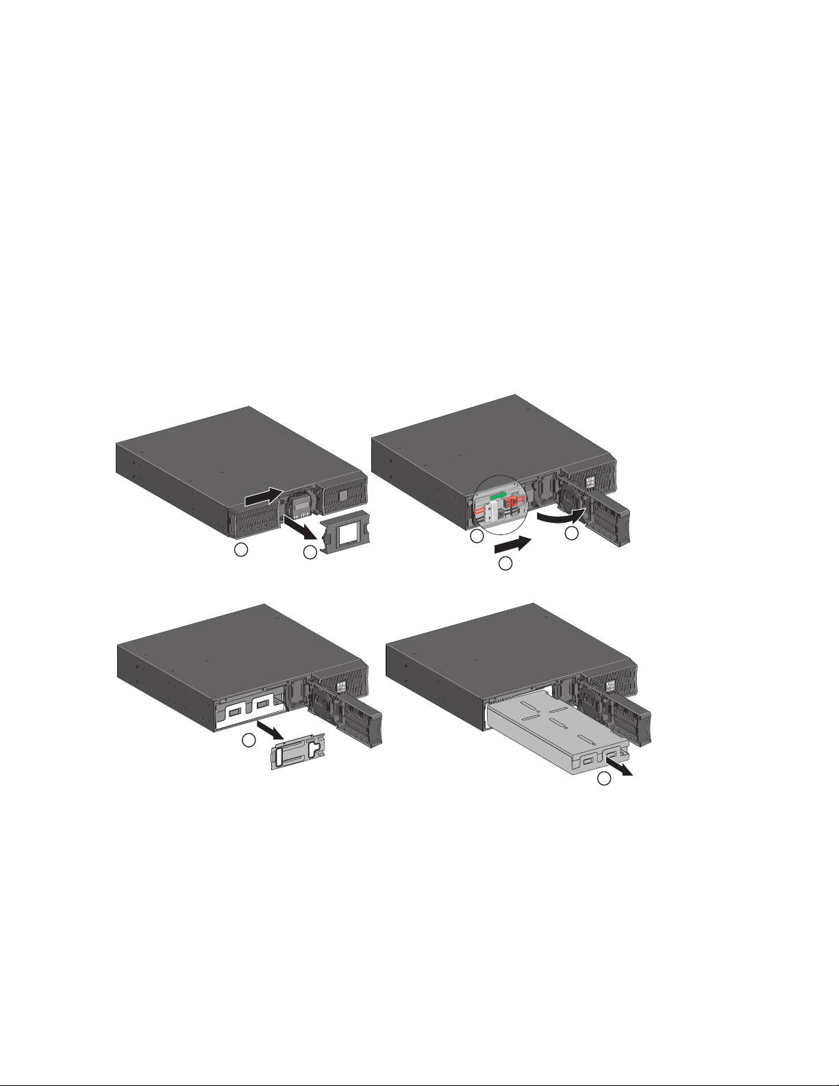
Replacing the internal battery
The internal battery is heavy. Use caution when handling the heavy batteries.
Figure 17. Internal Battery Pack Replacement
5
6
7
4
3
1
2
To replace the battery pack:
1. Remove the center cover of the front panel.
2. Push left cover toward to right direction.
3. Open the battery door.
4. Disconnect the battery connectors.
A ribbon cable connects the LCD control panel to the UPS. Do not pull on the cable or disconnect it.
Replacing batteries

Tripp Lite by Eaton SmartOnline Series User Guide 614-21325—Rev 01 35
5. Remove the two screws to pull out the metal protection cover of the battery.
6. Pull out the plastic handle of the battery pack, and slide the pack out slowly on to a flat and stable surface.
Use two hands to support the battery pack. See 5.5 Recycling the used equipment for proper disposal.
7. Verify that the replacement batteries have the same rating as the batteries being replaced.
8. Put the new battery pack into the UPS. Push the battery pack firmly, reconnect the red and black battery
connectors.
9. Verify that all of the alarms have cleared on the display.
10. Screw back the metal protection cover and the front panel, then clip the center cover.
Replacing the extended battery pack(s)
The extended battery pack is heavy. Lifting the cabinet into a rack requires a minimum of two people.
To replace the extended battery pack(s):
1. Unplug the extended battery pack power cable and battery detection cable from the UPS. If additional
extended battery pack(s) are installed, unplug the extended battery pack power cable and battery detection
cable from each extended battery pack.
2. Replace the extended battery pack(s). See "5.5 Recycling the used equipment" for proper disposal.
A small amount of arcing may occur when connecting an extended battery pack to the UPS. This is normal
and will not harm personnel. Insert the extended battery pack cable into the UPS battery connector quickly
and firmly.
3. Plug the extended battery pack cable(s) into the battery connector(s). Up to four extended battery packs
may be connected to the UPS.
4. Verify that the extended battery pack connections are tight and that adequate bend radius and strain relief
exist for each cable.
5. Connect the battery detection cable(s) to the connector of the UPS and of the extended battery pack(s).
TTeessttiinngg nneeww bbaatttteerriieess
To test new batteries:
1. Press any button to activate the menu options.
2. Select Control then Start battery test.
The UPS starts a battery test if the batteries are fully charged, the UPS is in Normal mode with no active
alarms, and the bypass voltage is acceptable.
During the battery test, the UPS transfers to Battery mode and discharges the batteries for 25 seconds.
The front panel displays "Battery test in progress" and the percentage of the test completed.
NOTE The UPS load percentage must be greater than 10% in order to run a battery test.
Replacing batteries

36 Tripp Lite by Eaton SmartOnline Series User Guide 614-21325—Rev 01
55..55 RReeccyycclliinngg tthhee uusseedd eeqquuiippmmeenntt
Contact your local recycling or hazardous waste center for information on proper disposal of the used
equipment.
RISK OF ELECTRIC SHOCK - Observe the warning associated with the risk of electric
shock symbol.
This symbol indicates that you should not discard the UPS or the UPS batteries in the
trash. This product contains sealed lead acid batteries and must be disposed of properly.
For more information, contact your local recycling/reuse or hazardous waste center.
Special Symbols
The following are examples of symbols used on the UPS or accessories to alert you to important
information:
RISK OF ELECTRIC SHOCK - Observe the warning associated with the risk of
electric shock symbol.
CAUTION: REFER TO OPERATOR'S MANUAL - Refer to your operator's manual for
additional information, such as important operating and maintenance
instructions.
This symbol indicates that you should not discard the UPS or the UPS batteries
in the trash. This product contains sealed, lead‐acid batteries and must be
disposed of properly. For more information, contact your local recycling/reuse or
hazardous waste center.
This symbol indicates that you should not discard waste electrical or electronic
equipment (WEEE) in the trash. For proper disposal, contact your local
recycling/reuse or hazardous waste center.
Eaton, Powerware, and BladeUPS are registered trademarks of Eaton Corporation or its subsidiaries and affiliates.
Phillips and Pozidriv are registered trademarks of Phillips Screw Company.
ECopyright 2008–2010 Eaton Corporation, Raleigh, NC, USA. All rights reserved. No part of this document may be
reproduced in any way without the express written approval of Eaton Corporation.
This symbol indicates that waste electrical and electronic equipment as well as waste
batteries and accumulators should not be discarded together with unseparated
household waste, but must be collected separately. The product should be handed in for
recycling in accordance with the local environmental regulations for waste disposal. By
separating waste electrical and electronic equipment as well as waste batteries and
accumulators, you will help reduce the volume of waste sent for incineration or land-fills
and minimize any potential negative impact on human health and environment.
Recycling the used equipment
Tripp Lite by Eaton SmartOnline Series User Guide 614-21325—Rev 01 37
CChhaapptteerr 66 TTrroouubblleesshhoooottiinngg
66..11 TTyyppiiccaall AAllaarrmmss aanndd FFaauullttss
The SmartOnline series UPS units are designed for durable, automatic operation and also alert you whenever potential
operating problems may occur. Usually the alarms shown by the control panel do not mean that the output power is affected.
Instead, they are preventive alarms intended to alert the user.
• Events are silent status information that are recorded into the Event log. Example = "AC freq in range".
• Alarms are recorded into the Event log and displayed on the LCD status screen with the logo blinking.
Some alarms may be announced by a beep every 3 seconds. Example = "Battery low".
• Faults are announced by a continuous beep and red LED, recorded into the Fault log and displayed on the
LCD with a specific message box. Example = Out. short circuit.
Use the following troubleshooting chart to determine the UPS alarm condition.
Checking the Alarms and Faults
The following table describes typical conditions. SeeTable 9 and Table 10 for more detailed fault and alarm
codes.
Table 8. Typical UPS Conditions
Conditions Possible cause Action
Battery mode
LED is On.
1 beep every 10 seconds
A utility failure has occurred and the UPS
is in battery mode.
The UPS is powering the equipment with
battery power. Prepare your equipment
for shutdown.
Battery mode
LED is On.
1 beep every 3 seconds
The UPS is in Battery mode and the
battery is running low.
This warning is approximate, and the
actual time to shutdown may vary
significantly. Depending on the UPS load
and number of Extended Battery Modules
(EBMs), the "Battery Low" warning may
occur before the batteries reach 0%
capacity.
No battery
LED is On
Beep continuous
The batteries are disconnected. Verify that all batteries are properly
connected. To clear a battery
disconnected alarm a battery test must
be initiated. If the condition persists,
contact your service representative.
Battery fault
LED is On
Beep continuous
The battery test is failed due to bad or
disconnected batteries.
Verify that all batteries are properly
connected. If the condition persists,
contact your service representative. To
clear a battery disconnected alarm a
battery test must be initiated. If the
condition persists, contact your service
representative.
The UPS does not provide the expected
backup time.
The batteries need charging or service. Apply utility power for 48 hours to charge
the batteries. If the condition persists,
contact your service representative.
38 Tripp Lite by Eaton SmartOnline Series User Guide 614-21325—Rev 01
Table 8. Typical UPS Conditions (Continued)
Conditions Possible cause Action
Bypass mode
LED is on.
An overload or a fault has occurred, or a
command has been received and the UPS
is in Bypass
Equipment is powered but not protected
by the UPS. Check for one of the
following alarms: overtemperature,
overload or UPS LED is on. failure.
Power Overload
LED is on.
Power requirements exceed the UPS
capacity (greater than 100% of nominal;
see “User Settings” for specific output
overload ranges).
Remove some of the equipment from the
UPS. The UPS continues to operate, but
may switch to Bypass mode or shut down
if the load increases. The alarm resets
when the condition becomes inactive.
UPS Overtemperature
LED is on.
1 beep every 3 seconds
The UPS internal temperature is too high
or a fan has failed. At the warning level,
the UPS generates the alarm but remains
in the current operating state. If the
temperature rises another 10°C, the UPS
transfers to Bypass mode or shuts down
if Bypass is unusable.
If the UPS transferred to Bypass mode,
the UPS will return to normal operation
when the temperature drops 5°C below
the warning level. If the condition
persists, shut down the UPS.
Clear vents and remove any heat sources.
Allow the UPS to cool. Ensure the airflow
around the UPS is not restricted. Restart
the UPS. If the condition continues to
persist, contact your service
representative.
The UPS does not start
The input source is not connected
correctly.
Check the input connections.
The Remote Power Off (RPO) switch is
active or the RPO connector is missing.
If the UPS Status menu displays the
"Remote Power Off" notice, inactivate the
RPO input.
Table 9. UPS Fault Codes
Fault Code
Displayed Alarm
Potential Cause
007 FAN FAULT
Fan don’t work normally or Fan detection circuit is
abnormal
107 INPUT BAD WIRING
Refer to Site Wiring Fault
207 BP DEVICE FAULT
Bypass relay is stuck or driver circuit is abnormal
208 BP OVERLOAD
Bypass overload faultI > 125% (max counter
reached)
300 DC BUS+ TOO HIGH
Overload/improper load type/ input high pulse
/PSDR damaged /CNTL damaged
301 DC BUS- TOO HIGH
Overload/improper load type/ input high pulse
/PSDR damaged /CNTL damaged
302 DC BUS+ TOO LOW
Overload/improper load type/PSDR/CNTL damaged
303 DC BUS- TOO LOW
Overload/improper load type/PSDR/CNTL damaged
304 DC BUS UNBALANCE
Overload/improper load type/PSDR/CNTL damaged
Typical Alarms and Faults

Tripp Lite by Eaton SmartOnline Series User Guide 614-21325—Rev 01 39
Table 9. UPS Fault Codes (Continued)
Fault Code
Displayed Alarm
Potential Cause
305 RECT FAULT
Hardware fault in the rectifier /PFC
308 DC BUS SHORTED Dc bus short circuit
400 DCDC FAULT
Hardware fault in the DCDC part
500 CHARGER FAULT
Charger internal failure
502 MAX CHARGER VOLT
Recharge battery voltage is too high
503 MIN CHARGER VOLT
If battery voltage has not reached UchargeEnd
within tchargeMax then go to Float mode.
In that case if battery voltage is < 2.25 VPC then
“Charger fault” alarm is set.
tchargeMax = 24h x Number of EBM
607 BATTERY FAULT
Battery need replacement OR is faulty
700 CURRENT LIMIT
Current limitation (due to limitation, UPS has
transfered to bypass or stop)
706 UPS TEMP. FAULT
UPS internal temperature is high (due to
temperature, UPS has transfered to bypass or
stop)
70C MIN INV VOLT
Inverter voltage is too low
70D MAX INV VOLT
Inverter voltage is too high
805 OUTPUT SHORTED
short circuit on output
808 INV OVERLOAD
Inverter overload
Max (P,S) > L2 (L2 = 102%) max counter reached
C39 NVM NO RESPONSE
EEPROM can’t read/write normally
815 CALIBRATION FLT
DC offset of INV voltage is too high
00F MODEL ERROR
ATE set country error(stored in COM board
EEPROM).
Table 10. UPS Alarm Codes
Alarm Code
Displayed Alarm
Potential Cause Action
001 AC LOSS
Main AC is below charger
level
Check AC mains
004 AMB. TEMP. ALARM
Ambient temperature is high
Please check ambient temperature and if
the ventilation is blocked
104 AC FREQ NOT OK
Frequency out of range Check AC Freq
106 AC VOLT NOT OK
Voltage out of range
Check AC Volt
Typical Alarms and Faults

40 Tripp Lite by Eaton SmartOnline Series User Guide 614-21325—Rev 01
Table 10. UPS Alarm Codes (Continued)
Alarm Code
Displayed Alarm
Potential Cause Action
110 BUILDING ALARM
building alarm by input signal
contactor
200 BP PHASE NOT OK
Phase out of range (bypass
input and inverter output
cannot phase lock)
Check Bypass AC frequency
206 BP FREQ. NOT OK
Frequency out of range Check Bypass AC frequency
208 BP OVERLOAD
Bypass overload alarm
Check and reduce load
209 BP VOLT NOT OK
Input Voltage out of bypass
range
Please check input voltage
603 BATTERY MODE
Battery is discharging Please check input voltage
604 BATTERY LOW
Battery level is below
RemainingCapacityLimit
threshold or RunTimetoEmpty
is below RemainingTimeLimit
threshold.
Please check the mains and Prepare to
shut off load
60D NO BATTERY
Battery not present
Please check if batteries are connected
rightly or fuse is open
612 BAT TEST ABORTED
Battery test condition is not
met.
Check: UPS mode is AC (online) or HE;
Load must be greater than 10%;
Battery capacity should be >=80%;
There is no running alarm (excepted
Battery fault);
Load level has not varied by more than
+/- 10 percent (from the initial load level
present at the beginning of the test to
the beginning of step2 test).
700 CURRENT LIMIT inverter current limitation Check load
706 UPS TEMP. ALARM
UPS internal temperature is
high
Please check ambient temperature and if
the ventilation is blocked, and if fan
works normal.
802 IMMINENT SHUTOFF
shut down imminent for
battery low
Please prepare for shutdown
806 EMERGENCY OFF
emergency stop was proceed
Please check if RPO is active
80E OVLD PREALARM
output power above threshold
102%(default), settable from
HMI.
Check overload pre-alarm setting and
load
810 POWER OVERLOAD
Output power overload, Max
(P,S) > L2 (L2 = 102%)
Please check the load capacity
Typical Alarms and Faults

Tripp Lite by Eaton SmartOnline Series User Guide 614-21325—Rev 01 41
66..22 SSiilleenncciinngg tthhee AAllaarrmm
Press the ESC (Escape) button on the front panel display to silence the alarm. Check the alarm condition and
perform the applicable action to resolve the condition. If the alarm status changes, the alarm beeps again,
overriding the previous alarm silencing.
66..33 SSeerrvviiccee aanndd SSuuppppoorrtt
If you have any questions or problems with the UPS, call the Eaton technical support helpdesk at 800–356–
5737 or your local service representative and ask for a UPS technical representative. Please have the following
information ready when you call for service:
• Model number
• Serial number
• Firmware version number
• Date of failure or problem
• Symptoms of failure or problem
• Customer return address and contact information
If repair is required, you will be given a Returned Material Authorization (RMA) number. This number must
appear on the outside of the package and on the Bill Of Lading (if applicable). Use the original packaging or
request packaging from the Help Desk or distributor. Units damaged in shipment as a result of improper
packaging are not covered under warranty. A replacement or repair unit will be shipped, freight prepaid for all
warrantied units.
Silencing the Alarm

Tripp Lite by Eaton SmartOnline Series User Guide 614-21325—Rev 01 43
CChhaapptteerr 77 SSppeecciiffiiccaattiioonnss
77..11 MMooddeell SSppeecciiffiiccaattiioonnss
Input
Filter
AC/DC
Boost
DC/AC
Inverter
Outpout
Filter
Bypass
DC/DC
Battery
Charger
Table 11. Power Module List
Catalog Number (UPS)
Power ratings
SU750RTXLCD2U / SU750RTXLCD2UN 750VA / 675W
SU1000RTXLCD2U / SU1000RTXLCD2UN 1000VA / 900W
SU1500RTXLCD2U / SU1500RTXLCDN 1500VA / 1350W
SU2200RTXLCD2U / SU2200RTXLCDN 2000VA / 1800W
SU3000RTXLCD2U / SU3000RTXLCD2UN 3000VA / 2700W
SUINT1000LCD2U
1000VA / 900W
SUINT1500LCD2U
1500VA / 1350W
SUINT2200LCD2U
2200VA / 2000W
SUINT3000LCD2U
3000VA / 2700W
Table 12. Extended Battery Module List
Catalog Number (UPS) Configuration Battery Voltage
For Power Module
BP36RT
Rack / Tower
36Vdc 750 – 1000VA LV Models
BP48RT
Rack / Tower
48Vdc
1500VA LV Model
1000 – 1500VA SUINT Models
BP72RT
Rack / Tower
72Vdc
2000 – 3000VA LV Models
2200– 3000VA SUINT Models
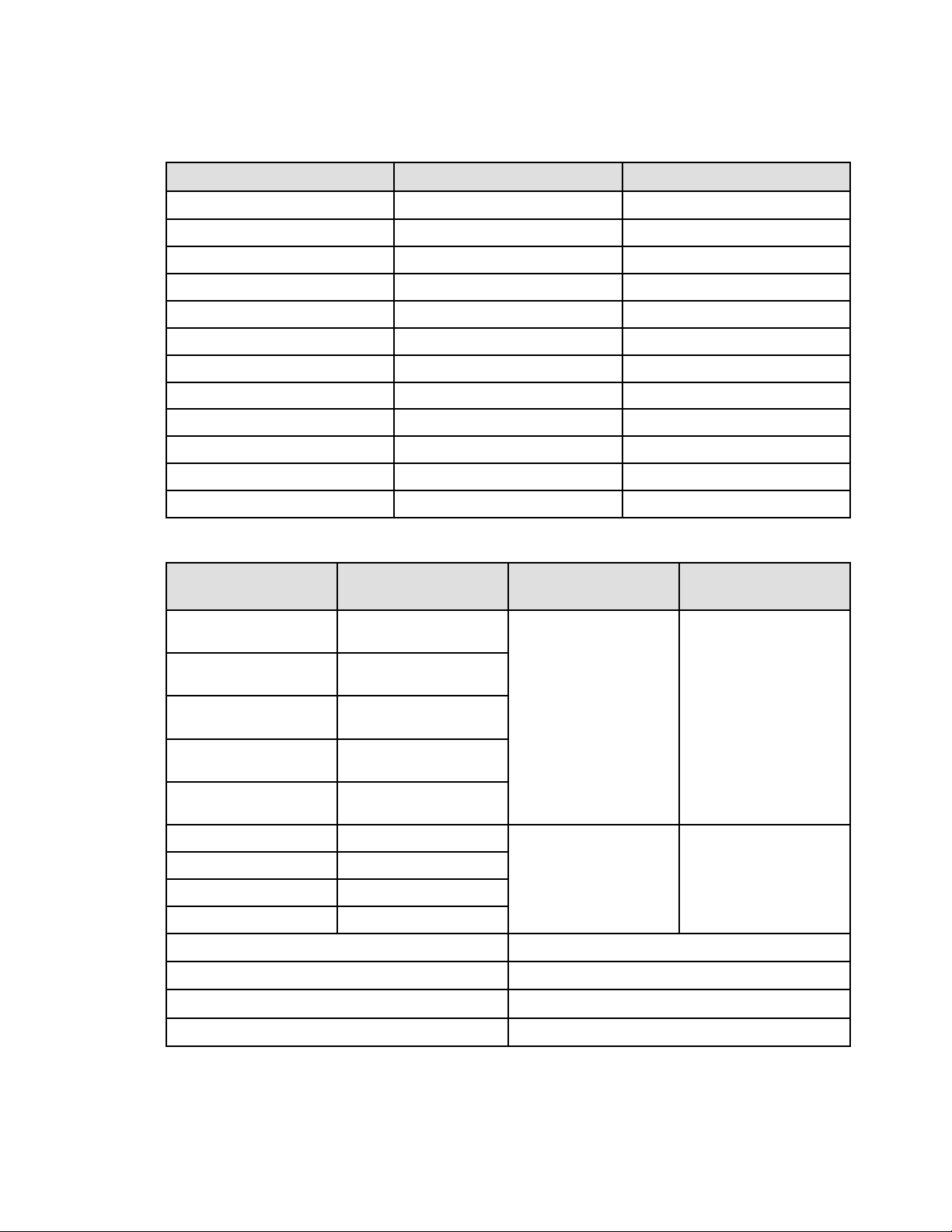
44 Tripp Lite by Eaton SmartOnline Series User Guide 614-21325—Rev 01
Table 13. Weights and Dimensions
Model
Weight (lb / kg) Dimensions D x W x H(inch/mm)
SU750RTXLCD2U / SU750RTXLCD2UN
36.4 / 16.5 17.7 x 17.3 x 3.4 / 450 x 440 x 86.5
SU1000RTXLCD2U / SU1000RTXLCD2UN 36.4 / 16.5 17.7 x 17.3 x 3.4 / 450 x 440 x 86.5
SU1500RTXLCD2U / SU1500RTXLCDN
42.5 / 19.3 17.7 x 17.3 x 3.4 / 450 x 440 x 86.5
SU2200RTXLCD2U / SU2200RTXLCDN 61.6 / 27.9 23.8 x 17.3 x 3.4 / 605 x 440 x 86.5
SU3000RTXLCD2U / SU3000RTXLCD2UN 63 / 28.6 23.8 x 17.3 x 3.4 / 605 x 440 x 86.5
SUINT1000LCD2U 36.4 / 16.5 17.7 x 17.3 x 3.4 / 450 x 440 x 86.5
SUINT1500LCD2U
41.4 / 18.8 17.7 x 17.3 x 3.4 / 450 x 440 x 86.5
SUINT2200LCD2U 59.7 / 27.1 23.8 x 17.3 x 3.4 / 605 x 440 x 86.5
SUINT3000LCD2U 61.2 / 27.8 23.8 x 17.3 x 3.4 / 605 x 440 x 86.5
BP36RT 48.1 / 21.8 17.7 x 17.3 x 3.4 / 450 x 440 x 86.5
BP48RT 59.5 / 27 17.7 x 17.3 x 3.4 / 450 x 440 x 86.5
BP72RT 86.4 / 39.2 23.8 x 17.3 x 3.4 / 605 x 440 x 86.5
Table 14. Electrical Input
Catalog Number (UPS)
Default Input
(Voltage/Max Current)
Input Nominal Voltages Input Voltage Window at
Rated Load
SU750RTXLCD2U /
SU750RTXLCD2UN
120V / 6.2A
100V, 110V, 120V, 125V
100–138V
SU1000RTXLCD2U /
SU1000RTXLCD2UN
120V / 8.3A
SU1500RTXLCD2U /
SU1500RTXLCDN
120V / 12.5A
SU2200RTXLCD2U /
SU2200RTXLCDN
120V / 16A
SU3000RTXLCD2U /
SU3000RTXLCD2UN
120V / 24A
SUINT1000LCD2U
208V / 4.8A
200V, 208V, 220V, 230V, 240V
176–276V
SUINT1500LCD2U 208V / 7.2A
SUINT2200LCD2U 208V / 10.57A
SUINT3000LCD2U 208V / 14.42A
Nominal Frequency 50/60Hz auto-sensing
Frequency Range 40-70Hz before transfer to battery
Bypass Voltage Range
-20% / +15% of nominal value (default)
Noise Filtering Not Available for US Models
Model Specifications
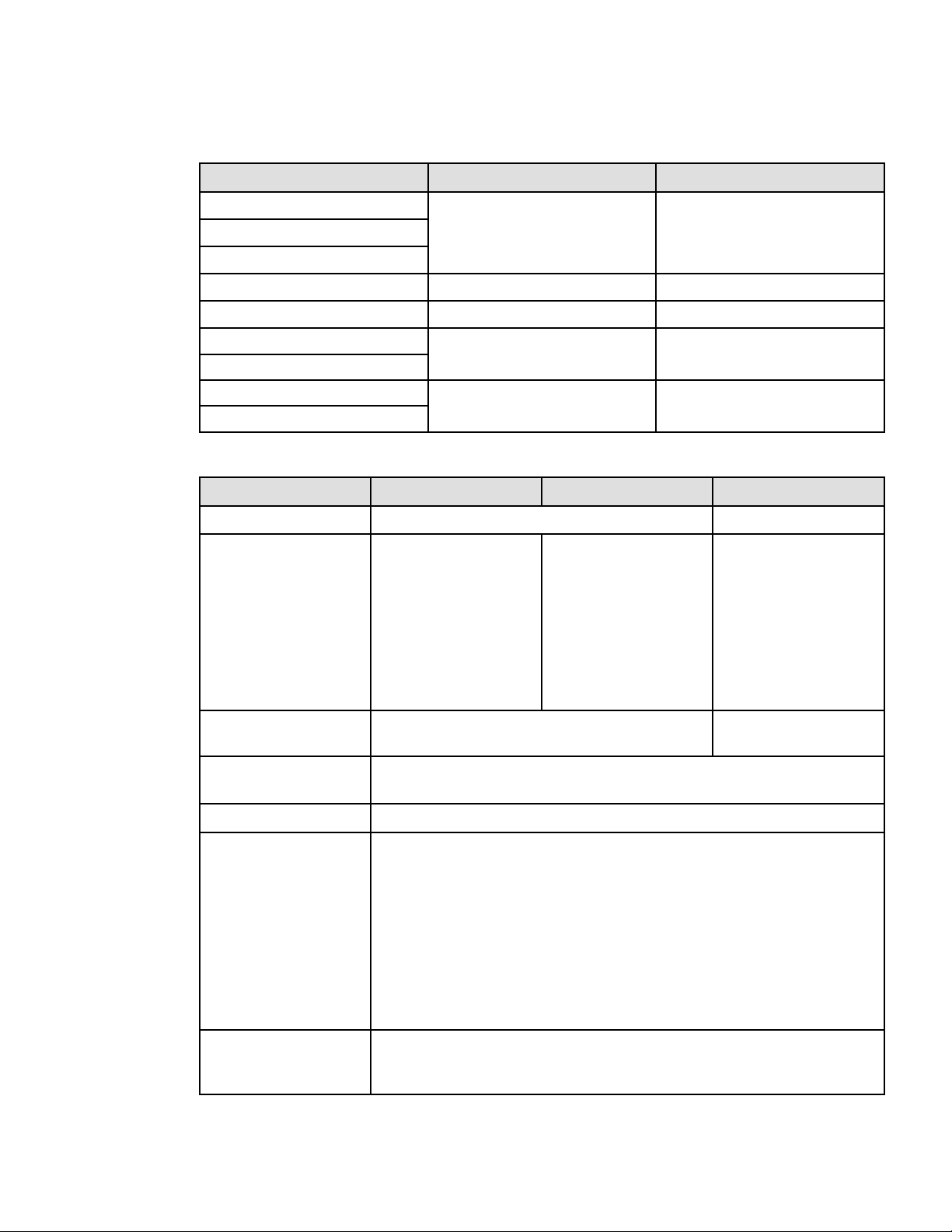
Tripp Lite by Eaton SmartOnline Series User Guide 614-21325—Rev 01 45
Table 15. Electrical Input Connections
Catalog Number (UPS)
Input Connection Input cable
SU750RTXLCD2U / SU750RTXLCD2UN
5–15P
Attached line cord 8ft / 2.4mSU1000RTXLCD2U / SU1000RTXLCD2UN
SU1500RTXLCD2U / SU1500RTXLCDN
SU2200RTXLCD2U / SU2200RTXLCDN
5–20P
Attached line cord 8ft / 2.4m
SU3000RTXLCD2U / SU3000RTXLCD2UN
L5–30P
Attached line cord 8ft / 2.4m
SUINT1000LCD2U
IEC-C14
6ft / 1.8m
SUINT1500LCD2U
SUINT2200LCD2U
IEC-C20 L6-20P to C19 jumper provided
6ft / 1.8m
SUINT3000LCD2U
Table 16. Electrical Output
All Models Normal Mode Efficiency Mode Battery Mode
Voltage Regulation ±1% ±2%
Efficiency
89.9% for 750 LV models
90.3% for 1.K LV models
90.2% for 1K SUINT models
90% for 1.5K LV models
91% for 1.5K SUINT models
91.4% for 2K LV models
93% for 2K SUINT models
94% for 3K SUINT models
95.3% for 750 LV models
95.8% for 1K LV models
96% for 1K SUINT models
95.8% for 1.5K LV models
96.5% for 1.5K SUINT models
96.8% for 2K LV models
98% for 2K SUINT models
97.2% for 3K LV models
98% for 3K SUINT models
83% for 750 LV models
83% for 1K LV models
87.5% for 1K SUINT models
84% for 1.5K LV models
87.5% for 1.5K SUINTmodels
86% for 2K LV models
90% for 2K SUINT models
86% for 3K LV models
89% for 3K SUINT models
Frequency Regulation
Sync with line ±5% of nominal line frequency (outside this
range: ±0.5% of auto-selected nominal frequency)
±0.5% of auto-selected
nominal frequency
Nominal Output
[100V] [110V] [120V] [125V] (LV models)
[200V] [208V] [220V] [230V] [240V] (SUINT models)
Frequency 50 or 60 Hz, autosensing follows the input frequency
Output Overload
Online mode:
102%~130% :12s
130%~150% :2s
>150% :shutdown after 300ms
Percent is based on nominal Watt/VA.
Transfer behavior can change (see output mode setting on page 14)
Battery mode:
102%~130% :12s
>130% :2s
Overload warning then transfer to stop output
Output Overload ( Bypass
Mode )
102%~110% :Overload warning
110%~130% :shutdown after 5mins
130%~150% :shutdown after 15s
Model Specifications
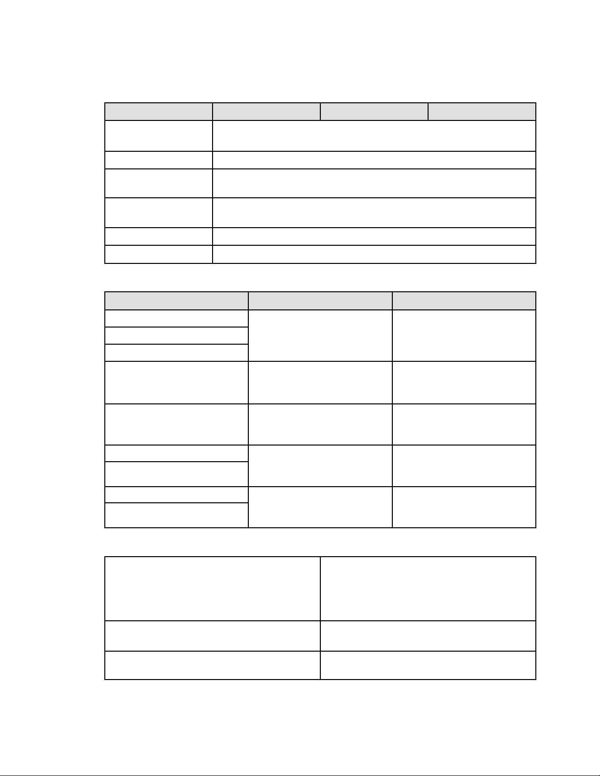
46 Tripp Lite by Eaton SmartOnline Series User Guide 614-21325—Rev 01
Table 16. Electrical Output (Continued)
All Models Normal Mode Efficiency Mode Battery Mode
>150% :shutdown after 300ms
Percent is based on nominal current in bypass mode
Voltage Waveform Sinewave
Harmonic Distortion
< 3% THDV on linear load
< 5% THDV on non-linear load
Transfer Time Online Mode: 0ms
High Efficiency mode: 10ms maximum (due to loss of utility)
Power Factor Up to 0.9
Load Crest Ratio
Up to 3:1
Table 17. Electrical Output Connections
Model Output Connection Output Cable
SU750RTXLCD2U / SU750RTXLCD2UN (4) 5–15R Primary
(2) 5–15R Group 1
(2) 5–15R Group 2
No
SU1000RTXLCD2U / SU1000RTXLCD2UN
SU1500RTXLCD2U / SU1500RTXLCDN
SU2200RTXLCD2U / SU2200RTXLCDN
5-20R(2) + L5-20R(1) Primary
5-20R(2) Group1
5-20R(2) Group2
No
SU3000RTXLCD2U / SU3000RTXLCD2UN 5-20R(2) + L5-30R(1) Primary
5-20R(2) Group1
5-20R(2) Group2
No
SUINT1000LCD2U (4) IEC320 10A Primary
(2) IEC320 10A Group 1
(2) IEC320 10A Group 2
No
SUINT1500LCD2U
SUINT2200LCD2U (4) IEC320 10A + (1) IEC320 16A Primary
(2) IEC320 10A + (1) IEC320 16A Group 1
(2) IEC320 10A Group 2
(2) IEC320 10A
SUINT3000LCD2U
Table 18. Environmental and Safety
Certifications
IEC/EN 62040-1
IEC/EN 62040-2 : Cat. C2
IEC/EN 62040-3
UL1778 5th edition
CSA 22.2
EMC
EN IEC 62040–2: C2
FCC part 15 Class A/ ICES-003 (A)
Agency Markings
cTUVus/NOM(TUV NOM)/CE (SU750RTXL- SU1500RTXLCD
Models)
Model Specifications

Tripp Lite by Eaton SmartOnline Series User Guide 614-21325—Rev 01 47
Table 18. Environmental and Safety (Continued)
cTUVus/NOM(TUV NOM)/Energy-star/CE (SU2200RTXL —
SU3000RTXL Models)
cTUVus/Energy-star/CE/UKCA (SUINT1000LCD - SUINT3000LCD
Models)
CE/cTUVus- (BP36RT — BP72RT Models)
Operating Temperatures
0 to 40 °C (32 to 104 °F) in Online mode, with linear derating
for altitude
Note: thermal protection switches load to Bypass in case of
overheating.
Protective class I
Output short-circuit current max RMS & delay time 68A/7 cycles; The max peak value: 92A
This UPS can be used in and supplied to load TN/TT/IT power system for HV models, TN power system for LV models.
UPS enclosure IP rating
IP20
Storage Temperatures
0 to 40°C (32 to 104°F) with batteries
-25 to 55°C (-13 to 130°F) without batteries
Transit Temperature
-25 to 55°C (-13 to 130°F)
Relative Humidity 0 to 96% no condensing
Operating Altitude
Up to 3,000 meters (9,843 ft) above sea level, no derating for
35°c (95°F) room temperature
Transit Altitude
Up to 10,000 meters (32,808 ft) above sea level
Audible Noise
< 50 dBA at 1 meter typical
Table 19. Battery
Internal Batteries EBM
Rack / Tower configuration
750VA: 36Vdc
1000VA LV: 36Vdc
1000VA INT: 48Vdc
1500VA: 48Vdc
2200VA: 72Vdc
3000VA: 72Vdc
BP36RT: 36Vdc- 2 x 3 x 12V. 9Ah
BP48RT: 48Vdc- 2 x 4 x 12V. 9Ah
BP72RT: 72Vdc- 2 x 6 x 12V. 9Ah
Type
Sealed, maintenance-free, valve-regulated, lead-acid, with minimum 3-year float
service life at 25 °C (77 °F). Lifetime is reduced above 25°C (77°F)
EBM Battery Cable Length
350 mm / 13.78 in
Model Specifications

614-2132501
614-21325 01